
Create successful ePaper yourself
Turn your PDF publications into a flip-book with our unique Google optimized e-Paper software.
Dedicated Customer Support<br />
1-800-663-8932<br />
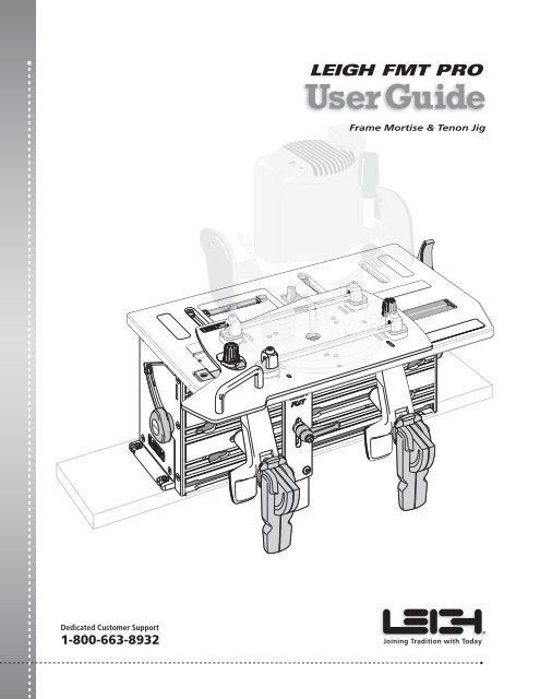
<strong>LEIGH</strong> <strong>FMT</strong> <strong>PRO</strong><br />
Frame Mortise & Tenon Jig<br />
<strong>Leigh</strong> Router Joinery <strong>Jigs</strong><br />
Joining Tradition with Today
ii Frame Mortise & Tenon Jig User Guide<br />
Your New <strong>Leigh</strong> Frame Mortise & Tenon Jig (<strong>FMT</strong> Pro)<br />
Congratulations for selecting the unique <strong>Leigh</strong> <strong>FMT</strong> Pro, the best<br />
mortising and tenoning jig available. The <strong>FMT</strong> Pro will allow you<br />
to rout a large range of sizes of mortise and tenon joints with total<br />
control over joint fit.<br />
To gain the most advantage from this unique tool, please read all<br />
of this User Guide; carefully set up the jig following the simple<br />
set-up directions, and thoroughly familiarize yourself with the<br />
basic functions and principles of operation. Use scrap wood before<br />
attempting any actual projects with valuable hardwood.<br />
If you have any questions that are not answered in this manual,<br />
please call the <strong>Leigh</strong> Customer Support line*.<br />
But remember, “If at first you don’t succeed, read the instructions!”.<br />
*See Appendix IV - Customer Support.<br />
Important! Inches and Millimeters.<br />
The <strong>Leigh</strong> <strong>FMT</strong> Pro is available in two models; Inch or Metric.<br />
The only difference is in the guides and bits used, otherwise the<br />
jig itself is identical. Text and illustrations in this English language<br />
User Guide indicate dimensions in both inches and millimeters,<br />
with “inches” first, followed by “millimeters” in square brackets,<br />
i.e. 1 ⁄2"x2"[12x50mm].<br />
Do not be concerned that the inch/millimeter equivalents are<br />
not mathematically “correct”. Just use the dimensions that apply<br />
to your guides and bits.
Contents<br />
Frame Mortise & Tenon Jig User Guide<br />
CHAPTER 1 Mounting the <strong>FMT</strong> Pro .................................................................1<br />
CHAPTER 2 Mounting the Router ...................................................................3<br />
CHAPTER 3 The <strong>FMT</strong> Pro Jig ...........................................................................11<br />
The Clamp Plate and Clamping ................................................11<br />
The Table ......................................................................................14<br />
Jig Operation Concept ...............................................................16<br />
Safety and Router Operation ...................................................17<br />
Wood Preparation ......................................................................19<br />
CHAPTER 4 Mortise & Tenon Procedures .....................................................21<br />
Single Mortise & Tenon, Test .....................................................21<br />
Production Procedures ..............................................................27<br />
Small Joints ..................................................................................28<br />
CHAPTER 5 Multiple Joints ............................................................................31<br />
Double Joints ..............................................................................31<br />
Twin Joints ...................................................................................33<br />
Quadruple Joints ........................................................................35<br />
Triple Joints .................................................................................37<br />
CHAPTER 6 Workpiece and Joint Options ...................................................41<br />
Different Workpiece Thicknesses .............................................41<br />
Longer and Shorter Joints .........................................................42<br />
Thicker and Wider Boards .........................................................44<br />
CHAPTER 7 Special Joints ...............................................................................47<br />
Angled Joints ..............................................................................47<br />
Through Tenons ..........................................................................48<br />
Bridle Joints .................................................................................50<br />
Asymmetric Tenons ....................................................................51<br />
Haunched Joints .........................................................................51<br />
Doweling .....................................................................................54<br />
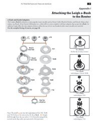
Appendix I Joint Specifications, Guide and Bit Selection .........................55<br />
Joint Specifications .....................................................................55<br />
Guide and Bit Selection .............................................................57<br />
Appendix II Jig Adjustments ..........................................................................61<br />
Appendix III Parts List ......................................................................................63<br />
Appendix IV Customer Support ......................................................................69<br />
iii
iv Frame Mortise & Tenon Jig User Guide
1. The main Jig Body, complete with:<br />
1 Guide Track ➀<br />
2. Router Sub-Plate complete with:<br />
2 Guide Pins ➁<br />
3. 1 User Guide<br />
4. 1 Box Containing:<br />
A 2 Vacuum Hose Adaptors<br />
B 4 Jig Hold-down Nuts and Bolts 1 ⁄4"-20<br />
B 4 U-Posts with 4 set-screws and<br />
four 3 ⁄4"c/sink Screws<br />
B 4 1" c/sink Screws<br />
B 6 Hex Socket Button Head Screws 10x24 x 3 ⁄8"<br />
B 2 Hex Socket Button Head Screws M6<br />
C 4 High Shim Spacers<br />
C 4 Low Shim Spacers<br />
C 1 1 ⁄4" - 1 ⁄2" Centring Mandrel<br />
C 1 8-12mm Centring Mandrel<br />
D 1 5 ⁄16" HSS Spiral Upcut 1 ⁄2" shank<br />
E 2 Outrigger Bars with 4 screws and nuts<br />
F 1 <strong>Leigh</strong> Square Drive Screwdriver<br />
F 1 <strong>Leigh</strong> 1 ⁄8" Hex Ball Screwdriver<br />
F 1 5 ⁄64" Hex Key<br />
F 2 Router Hold-down Rods<br />
G 5 5 ⁄16" guides (or 6x8mm with <strong>FMT</strong> Pro-M)<br />
& 1 Guide stand<br />
H* 1 Side Stop Fence with lever*<br />
I 2 Clamp assemblies<br />
3<br />
MOUNTING THE <strong>FMT</strong> <strong>PRO</strong> 1<br />
<strong>FMT</strong> <strong>PRO</strong> CHAPTER 1<br />
Mounting the <strong>FMT</strong> Pro<br />
Jig Assembly and Mounting<br />
The <strong>Leigh</strong> <strong>FMT</strong> Pro comes almost fully assembled with all adjustments factory set, but...<br />
Before you start to set up your <strong>Leigh</strong> <strong>FMT</strong> Pro Jig, make sure you have received all the required parts.<br />
* IMPORTANT: Some illustrations show<br />
the side stop fence with a “knob”. All <strong>FMT</strong><br />
Pro jigs are shipped with a side stop fence<br />
with a “lever”, (see H, above right).<br />
Note: Any optional accessories that you ordered may also<br />
be inside the parts box, or packaged inside the main carton.<br />
If any of these items are missing from your order, please notify<br />
your supplier or <strong>Leigh</strong> Industries immediately.<br />
4<br />
4<br />
2<br />
1<br />
A B C D E<br />
F G H* I<br />
2<br />
Repacking<br />
Instructions<br />
1
2 Chapter 1 Frame Mortise & Tenon Jig User Guide MOUNTING THE <strong>FMT</strong> <strong>PRO</strong><br />
1<br />
5"[125+mm]<br />
15 3 /4"[400mm]<br />
35/16"[84mm] 1/2"[13mm]<br />
24"[600mm]<br />
1-1 Mounting the <strong>FMT</strong> Pro: Prepare a flat board at least<br />
3⁄4"[20mm] thick, a minimum of 24"x5"[600x125mm]. Drill four<br />
9⁄32"[7mm] holes on 15 3⁄4"x3 5⁄16"[400x84mm] centers, 1⁄2"[13mm] in<br />
from the front edge of the board ➀. Countersink ➁, or counter-bore<br />
➂ if board is thicker, the underside so that the four 1⁄4–20 x 1" long<br />
machine screws will project above the top surface by 3⁄8"[9,5mm] ➃.<br />
1-3 For routing long vertical rails it may be necessary to build<br />
a jig stand to mount securely on your bench. Make the stand and<br />
bench height combination sufficient to accept the board length<br />
you have in mind. The jig stand should be bolted securely to the bench.<br />
Make up a stable platform as shown here to stand on. Do not use<br />
a collapsible step stool, these are unstable and unsafe. ■<br />
4<br />
2<br />
3<br />
1-2 Turn the jig upside-down on two padded blocks ➀ (to<br />
protect the table and sight-knob). Using the four nuts and four<br />
countersunk machine screws, bolt the base board to the jig using<br />
the two nut recesses in each end housings. The 1⁄2"[13mm] front<br />
edge ➁ to the front of the jig (of course). Now you can clamp<br />
your <strong>FMT</strong> Pro to any bench.<br />
2<br />
1
MOUNTING THE ROUTER 3<br />
<strong>FMT</strong> <strong>PRO</strong> CHAPTER 2<br />
Mounting the Router<br />
Foreword<br />
Designing a completely universal mounting sub-base for all plunge routers is a challenge, many routers are not<br />
provided with threaded sub-base holes suitable for the stresses produced when routing joints with the <strong>FMT</strong> Pro.<br />
The <strong>Leigh</strong> <strong>FMT</strong> Pro universal Sub-Base Mounting provides not only great attachment strength, but also secure<br />
lateral anchoring for the router.<br />
Depending on your router model, fitting the Sub-Base to your router may take up to an hour …the first time<br />
only. Once fitted, the router can be removed in seconds for instant use elsewhere, and can be re-attached in about<br />
a minute for <strong>FMT</strong> Pro use.<br />
Mounting the Sub-Base correctly this first time is critical to the accuracy of the jig, so take your time and get it<br />
right the first time. Here’s how...<br />
Left<br />
Front<br />
Left<br />
Rear<br />
The <strong>FMT</strong> Pro must only be<br />
used with a plunge router. Never,<br />
ever use a fixed base router!<br />
6<br />
9<br />
1 2 3<br />
4<br />
5<br />
10<br />
7 6<br />
9 12<br />
3 21<br />
4<br />
5<br />
11 11 7<br />
7 10<br />
1 2 3<br />
12 9<br />
8<br />
6<br />
5<br />
4<br />
7<br />
10<br />
9<br />
3 21<br />
6<br />
Right<br />
Rear<br />
Right<br />
Front<br />
ROUTER MAKE HOLES NOTES<br />
LR RR LF RF<br />
AEG OFS 50 2<br />
BOSCH 1450, 1611EVS,<br />
1613EVS,1617EVS<br />
2<br />
BOSCH 1619 EVS 1 *1 1 *File notch in U-Post if req’d to avoid Turret<br />
CRAFTSMAN 2<br />
DEWALT 616/618<br />
3<br />
DEWALT 621<br />
1 3 1 3<br />
DEWALT 625<br />
2 Requires 1/16" packing shim. See 2-7<br />
ELU 97 1 3 1 3<br />
ELU MOF 131 2<br />
ELU MOF 177/02 2<br />
ELU 3304 3<br />
ELU 3338 2<br />
FESTOOL 900E, 1010 7<br />
FESTOOL OF1400 11 Use 2 #5130 screws provided. See 2-28<br />
FESTOOL OF2000 2<br />
FESTOOL OF2200 12 Use 2 #5130 screws provided. See 2-28<br />
FLEX OFT2926VV 5 Use 3 #6410 screws provided. See 2-28<br />
FREUD FT2000E 2<br />
HITACHI M12V<br />
2<br />
HITACHI M12VC<br />
4<br />
HITACHI TR12 2 **8 2 **To avoid Turret<br />
MAKITA 3600B 1<br />
MAKITA 3612BR 3 **6 **To avoid Turret<br />
MAKITA 3612C 3<br />
MAKITA RP 0910 4<br />
MAKITA RP 1100 Series<br />
4<br />
METABO OFE728 3<br />
METABO OFE1028 3<br />
METABO<br />
OFE1229 3<br />
MILWAUKEE 5616<br />
4<br />
RYOBI R-150 3<br />
RYOBI RE180PL 2<br />
RYOBI R-500 2<br />
RYOBI R-E600 2<br />
PORTER CABLE 693<br />
PORTER CABLE 890<br />
4<br />
10<br />
Use 3 #6410 screws provided. See 2-28<br />
PORTER CABLE 890 Type 2 4 Use screws from router base. See 2-28<br />
PORTER CABLE 7529, 8529 5 Use 3 #6410 screws provided. See 2-28<br />
PORTER CABLE 7539 *2 *Reverse U-Post to put screws outside rods<br />
TRITON, TRC001 31/4hp<br />
9 Use 4 No. 6677 1/4-20 x 3/8” Button<br />
TRITON, MOF 001 21/4hp<br />
9 Head socket screws<br />
2-1 The <strong>Leigh</strong> <strong>FMT</strong> Pro Sub-Base Place your router, the<br />
<strong>FMT</strong> Pro Sub-Base and all the mounting parts on a clear bench.<br />
From the Sub-Base diagram and chart on this page, find the make<br />
and model of your router.<br />
2-2 Mark the appropriate mounting holes on the Sub-Base. Use a<br />
non permanent medium e.g. chalk, sticky tape (ink will permanently<br />
stain the anodized surface).<br />
If you cannot find your router model listed here, you can get the<br />
latest updates at our website: www.leighjigs.com, or proceed to<br />
figure 2-34.<br />
Note: If the chart at left indicates your router is a "Direct Screw"<br />
mount (shaded routers) go directly to 2-28.
4 Chapter 2 Frame Mortise & Tenon Jig User Guide MOUNTING THE ROUTER<br />
2<br />
3<br />
1<br />
2-3 Most plunge routers will be mounted to the Sub-Base like this,<br />
with rods through the fence rod holes ➀ and clamped down with the<br />
U-Posts ➁, but it is essential that the correct shim spacers ➂ are<br />
selected.<br />
2-5 To measure the “rod height”, place the router on a bench.<br />
Either use a calliper ➀, or insert a rod (flat side up) and use a good<br />
rule to measure between the bench top and the bottom of the<br />
rod ➁.<br />
2<br />
1 2<br />
1<br />
2-7 Note: Use of the shim stops is essential, not only to provide the<br />
correct rod height but to also act as side-to-side stops for the router ➀.<br />
If the rod height of your router is less than 3⁄16"[4,5mm] you must<br />
provide a shop-made packing shim between the router and Sub-Base.<br />
We suggest one or more sheets of sandpaper ➁, rough side up. Don’t<br />
forget the center hole.<br />
1<br />
2<br />
1<br />
3<br />
0<br />
10<br />
20<br />
30<br />
40<br />
50<br />
2-4 Depending on the make and model of your router, the height<br />
between the underside of your router and the bottom of the rod<br />
hole ➀ will vary. This dimension will determine if you need to<br />
use low ➀ or high ➁ shim spacers, or possibly both together ➂.<br />
1 2 3<br />
2-6 If rod height is between 3 ⁄16"[4,5mm] and 3 ⁄8"[9,5mm],<br />
use low shim spacers ➀. If rod height is between 3 ⁄8"[9,5mm] and<br />
17 ⁄32"[13,5mm], use high shim spacers ➁. If rod height is between<br />
17 ⁄32"[13,5mm] and 3 ⁄4"[19,5mm], use both shim spacers ➂, with<br />
the high one on the bottom. Note: If the rod height is less than<br />
3 ⁄16"[4,5mm], see 2-7 below.<br />
2-8 Adjust the four U-Post set-screws with the set-screw end<br />
flush inside the arch of the posts ➀.<br />
1<br />
1<br />
2<br />
3
MOUNTING THE ROUTER<br />
1 2<br />
2-9 There are two lengths of U-Post screws; 3 ⁄4"[19mm] and<br />
1"[25mm]. The 3 ⁄4"[19mm] are factory fitted as a quality control<br />
measure. Use these for either the low or high shim spacers ➀.<br />
Change them for the 1"[25mm] screws if both shim spacers are<br />
used ➁.<br />
1 2<br />
2-11 In most cases, position the U-Post screw leg (see 2-9) to<br />
the inside of the rod ➀ or depending on the size and shape of the<br />
router base, to the outside ➁. Slide the shim-stops away from the<br />
router position ➂. These will be repositioned against the router<br />
later.<br />
1/4"<br />
1/2"<br />
3<br />
3<br />
8mm<br />
12mm<br />
2-13 Unplug the router.<br />
Note the collet size of the router. Choose the matching size centring<br />
mandrel and fit it into the router collet.<br />
Frame Mortise & Tenon Jig User Guide<br />
Chapter 2<br />
2-10 Using the four selected screws, lightly attach the four U-Posts<br />
and correct shim-stop combination through the previously marked<br />
slots or holes in the Sub-Base. The screws must enter from below<br />
➀. Only very lightly tighten; you will need to move the U-Posts<br />
and the shim-stops during setup.<br />
1<br />
2<br />
2-12 Place the Sub-Base flat down on the corner of a smooth<br />
bench, the handle to your near left ➀ and the guide pins touching<br />
the adjacent edges of the bench ➁.<br />
1<br />
2-14 Holding the router as you would in normal use, place it base<br />
down onto the Sub-Base; the rear of the router toward the rear of<br />
the Sub-Base and large notch ➀. Plunge and move the router so<br />
that the large diameter of the centring mandrel fits through the<br />
Sub-Base center hole…<br />
1<br />
2<br />
5
6 Chapter 2 Frame Mortise & Tenon Jig User Guide MOUNTING THE ROUTER<br />
2-15 …and touches flush to the bench. Lock the plunge.<br />
Concentricity of bit to Sub-Base bit hole is essential to <strong>FMT</strong><br />
Pro accuracy, so never mount the router without using the centring<br />
mandrel.<br />
2-17 Festool 900 and 1000 Series:<br />
Align the fence rod holes to the previously positioned U-Posts.<br />
2-19 Using the hex screwdriver, turn down the four U-Post setscrews<br />
until there is only very slight and even pressure on each<br />
end of both rods. Leave the shim stops in the outer position.<br />
2-16 Align the router so that the fence rod holes are parallel to<br />
the front edge of the Sub-Base except Festool 900 and 1000 Series<br />
(see below).<br />
1<br />
2<br />
3 3<br />
2-18 Loosen and raise any router fence rod knobs ➀. Move the U-Posts<br />
and adjust as necessary to slide the two hold-down rods through the<br />
U-Posts and router fence rod holes, flat side of rods on top ➁. Leave<br />
an equal amount of rod projecting through each U-Post ➂.<br />
Never use the router’s fence rod knobs ➀ to “help” secure the router.<br />
This places uneven pressure and could damage the router base.<br />
2-20 Check that the rods are still centered in the rod holes ➀ and<br />
check that the router collet can rotate without excessive binding in<br />
the Sub-Base hole. Mandrel touching side of hole is OK; mandrel<br />
binding tight is not! Move the router if required to allow mandrel<br />
to rotate.<br />
2<br />
1
MOUNTING THE ROUTER<br />
2-21 Tighten the top U-Post set-screws a little more securely to<br />
hold the bars and router.<br />
2-23 Repeat this procedure at the other end of the same rod to<br />
position the shim stop against the router base. Re-check the collet/<br />
mandrel for relatively free rotation. Turn the router around on the<br />
corner of the bench and repeat this procedure on the two U-Post<br />
assemblies on the second rod.<br />
2<br />
2<br />
1<br />
2-25 Here’s how to remove the router for use elsewhere:<br />
Loosen the four top U-Post set-screws ➀ Slide out the two rods ➁.<br />
Do not remove the U-Posts. In about a minute, the router is free<br />
to be used for other tasks.<br />
1<br />
Frame Mortise & Tenon Jig User Guide<br />
Chapter 2<br />
2-22 Slide the router/Sub-Base assembly on the corner of the<br />
bench so that one U-Post bottom screw is overhanging the edge.<br />
Loosen this screw just slightly (if necessary) to take any pressure<br />
off the shim spacer above. Push the Shim spacer in to touch the<br />
router base and, holding it in position against the router base,<br />
firmly tighten this bottom screw.<br />
2-24 Tighten the four U-Post set-screws to the rods. The hex driver has<br />
high leverage so use common sense when tightening. The rods will bow<br />
slightly. Objective: have the collet concentric to the bit hole; the four shim<br />
stops providing secure side thrust security, and the U-Posts clamping the rods<br />
which hold the router against the <strong>Leigh</strong> Sub-Base. Router /Sub-Base are now<br />
a unit. Release the plunge; remove and store the mandrel. You’re set to go.<br />
2-26 To re-mount the router: place the Sub-Base over the corner<br />
of the bench. Make sure surfaces are clean. Place the router on the<br />
Sub-Base with the centring mandrel in the center hole. Insert<br />
the fence rods. Evenly tighten the four U-Post set-screws. Check<br />
that the mandrel rotates freely. In about two minutes the router/<br />
Sub-Base assembly is ready for making mortises and tenons.<br />
7
8 Chapter 2 Frame Mortise & Tenon Jig User Guide MOUNTING THE ROUTER<br />
2-27 Hint: If you plan to fit a different make/model router and<br />
later use the current one again, you can greatly speed up the reinstallation<br />
of the first router by marking around the original four<br />
U-Post/shim-stop positions.<br />
2-29 Unplug the router. Remove the router’s plastic sub-base-base<br />
(except Festool 1400) and template guidebush adapter from the 7529<br />
or 8529. Remove the clear plastic dust cover from the top of the 8529<br />
router base (those screw holes are used to attach the <strong>Leigh</strong> <strong>FMT</strong> Pro<br />
Sub Base). Safely store the removed parts and screws for future use. Fit<br />
the correct shank sized centring mandrel to the collet. With the <strong>Leigh</strong><br />
Sub-Base on a flat bench corner, place the router on top and plunge<br />
the mandrel through to the bench and lock the plunge.<br />
PORTER CABLE<br />
693<br />
PORTER CABLE<br />
7529 and 8529<br />
(FLEX OFT2926VV)<br />
1<br />
MAKITA<br />
RP1100 SERIES<br />
FESTOOL<br />
1400 and 2200<br />
2-31 Note: Porter Cable 7529 & 8529 (Flex OFT2926VV) have<br />
two sets of 3 threaded holes. Use the inner circle of <strong>FMT</strong> Pro Sub-Base<br />
holes. The outer circle holes align with threaded holes, but are not deep<br />
enough for the screws. For Porter Cable (Flex) 693 & Makita RP1100<br />
series routers use the outer circle of Sub-Base holes. Firmly attach<br />
the Sub-Base using the three 6410 hex socket button head screws<br />
provided ➀. Do not use the router’s sub-base screws. Read 2-33!<br />
2-28 These routers do not have suitable through fence rod<br />
holes: Porter Cable 693, 890, 890 Type 2, 7529, 8529; Flex OFT<br />
2926VV; Festool 1400, 2200; Makita RP0910, Makita RP1100<br />
series; Triton TRC001, MOF001. We’ve provided Sub-Base holes<br />
and screws to mount these directly to the Sub-Base. Using Porter<br />
Cable 7529 and 8529 as examples, here’s how.<br />
2-30 Remove the router and stand it upside down on the bench.<br />
Depending on the router design, you may need to support it in a<br />
soft-padded vise. Place the Sub-Base upside down onto the router’s<br />
metal base with the mandrel centring the router to the base through<br />
the bit hole. Rotate the Sub-Base until the correct threaded screw<br />
holes in the router base align with the counter-bored holes in the<br />
Sub-Base. See below before fitting the screws.<br />
5130<br />
2-32 Festool 1400 series routers attach using the two No. 5130 screws<br />
provided, through base holes No. 11. Festool 2200 series routers attach<br />
using the two No. 5130 screws in the No. 12 holes.
MOUNTING THE ROUTER<br />
2-33 In addition to the base screws it is vital to attach the four<br />
U-Posts and four of the shim stops (either size) and position and<br />
tighten these against the edge of the router base to prevent lateral<br />
router movement. For correct positioning, see 2-10 through 2-12<br />
and 2-22 through 2-23. Note: Porter Cable 7529 and 8529 handles<br />
will be slightly angled (not parallel) to the <strong>FMT</strong> Pro Sub Base.<br />
2-35 Take the four U-Posts and by trial, establish which four<br />
Sub-Base slots or holes will serve to attach the U-Posts. Mark<br />
these with chalk or sticky tape and follow instructions 2-2 through<br />
2-26. ■<br />
Frame Mortise & Tenon Jig User Guide<br />
1<br />
Chapter 2<br />
2-34 If you have a plunge router that is not listed in the Sub-Base diagrams,<br />
it is essential that your router have two parallel fence rod holes<br />
through the router base. These must be at least 5⁄16[8mm] in diameter ➀.<br />
Fit the correct shank sized centring mandrel to your router, place it on the<br />
Sub-Base and plunge the mandrel into the base hole. Place the fence rods<br />
through the rod holes with an equal amount protruding at each end.<br />
9
10 Chapter 2 Frame Mortise & Tenon Jig User Guide MOUNTING THE ROUTER
The Clamp Plate and Clamping<br />
4<br />
0<br />
10 20 30<br />
2<br />
3-1 The clamp plate ➀ is adjustable up to 30˚ from vertical and<br />
is held securely by two quadrant knobs ➁. A set-screw ➂ allows for<br />
positive return to 90˚. To ensure flush and in-plane joints, it may<br />
be necessary to adjust the clamp-plate angle. See Appendix II, Jig<br />
Adjustments. An angle scale is provided, with an indicator adjustable<br />
to zero ➃.<br />
The clamp plate and cam-clamps are a self contained clamping<br />
area. Under no circumstances should any other jig component be<br />
used for clamping and no auxiliary clamping method used, other<br />
than as illustrated in this guide.<br />
3<br />
3-3 …like this ➂. For clamping very small workpieces see<br />
Chapter 4, Small Joints.<br />
3<br />
1<br />
3<br />
2<br />
THE <strong>FMT</strong> <strong>PRO</strong> 11 JIG<br />
<strong>FMT</strong> <strong>PRO</strong> CHAPTER 3<br />
The <strong>FMT</strong> Pro Jig<br />
The Clamp Plate and Clamping<br />
1<br />
The Table<br />
Jig Operation Concept<br />
Safety and Router Operation<br />
Wood Preparation<br />
3-2 The two clamps are powerful cam-action rocking-arm<br />
clamps with capacity from zero to 3"[76mm]. The T-bolt is inserted<br />
directly into the T-slot opening ➀, moved to desired position and<br />
brass thumb nut lightly tightened. Normally tenon workpieces<br />
will be clamped vertically ➁, and mortise workpieces horizontally<br />
like this ➂, or...<br />
3-4 Never force a cam-action clamp. It has great leverage, and<br />
using excessive force may damage the workpiece. The powerful<br />
clamp, combined with a non-slip clamping surface, requires only<br />
moderate clamping pressure to hold the workpiece securely in<br />
place.<br />
1
12 Chapter 3 Frame Mortise & Tenon Jig User Guide THE <strong>FMT</strong> <strong>PRO</strong> JIG<br />
3-5 A smooth, firm action is enough to engage the clamp.<br />
Rule of thumb: if you can’t throw the lever comfortably by strong<br />
thumb pressure, reduce the tension. A few minutes of trial and error<br />
testing will soon give you the feel for the correct clamp tension.<br />
3-7 The clamping pressure is the same whichever of the two<br />
directions the lever is thrown. But if the lever is uncomfortably<br />
positioned at the correct clamping pressure...<br />
3-9 Then adjust the clamp until the lever is in the correct position<br />
at the required pressure.<br />
3-6 Do not use the lever as a torque arm!<br />
Adjust the clamp pressure only with the clamp disengaged.<br />
3-8 ...release the clamp, remove the workpiece and turn the<br />
step-washer a quarter turn. The step height in the step-washer is<br />
one quarter of the thread pitch.<br />
2<br />
1<br />
3<br />
4 4<br />
3-10 The clamp T-Bolt Slots and “keyholes” allow for full clamping<br />
coverage. The two lower keyholes ➀ are for the rare requirement<br />
to clamp mortise boards between 4 3⁄4"[120mm] and 5 1⁄2"[140mm]<br />
wide ➁. Always clamp with the heel and toe of the clamp over<br />
the surface area of the clamp plate ➂.<br />
Never allow the clamp arm heel pad in these red shaded areas ➃,<br />
even if (particularly if) the mounting board or bench is there.<br />
4
THE <strong>FMT</strong> <strong>PRO</strong> JIG<br />
3-11 The clamp T-bolts nuts need only be lightly finger tightened<br />
to prevent accidental clamp movement. The nuts are knurled to<br />
provide a good finger grip.<br />
Never use a tool to tighten these nuts!<br />
3-13 The <strong>FMT</strong> Pro's side stop fence is attached in all modes by a<br />
single knob and T-bolt inserted to the center clamp plate slot ➀.<br />
Most tenon pieces are routed vertically, and for that purpose the<br />
short part of the fence ➁ acts as a T-square against the edge of the<br />
clamp plate ➂. In this mode the <strong>Leigh</strong> logo faces toward you.<br />
1<br />
3-15 Angled Joints: Remove the knob and T-bolt. Reverse the fence so<br />
the short end faces toward you ➀. The fence may now be set at any angle<br />
along the center clamp plate slot ➁ by tightening the knob.<br />
NOTE: Never rout tenons with the short part of the fence to the top, in<br />
the bit opening.<br />
1<br />
3<br />
2<br />
2<br />
Frame Mortise & Tenon Jig User Guide<br />
Chapter 3<br />
13<br />
3-12 The clamp plate is provided with twelve through-holes.<br />
If for any reason a facing board is required to be attached to the<br />
clamp plate, No.8 or M4 wood screws (not supplied) may be used<br />
from the rear. See chapter 4, Small Joints.<br />
1<br />
2<br />
3-14 The side stop fence is squared at the factory, but check your first<br />
test joints. If your router/bit is not perfectly perpendicular to the table<br />
adjust the side stop fence: slightly loosen the 'pivot' screw ➀ and the 'lock'<br />
screw ➁. Adjust the angle ➂ to match the bit and retighten. Rout test<br />
joints to confirm correct setting. Once locked in this position it should<br />
never need adjusting when used with that same router.<br />
2<br />
3-16 'Mortise steady': When routing mortises in small stock the piece<br />
may 'flutter' causing poor joint fit. Invert the fence with the short end<br />
up in the bit opening ➀. Clamp the mortise piece against the face of the<br />
short fence ➁ which is perfectly flush with the clamp plate face ➀. When<br />
routing mortises at the end of a board, always move the table as far as<br />
possible left or right to minimize the length of unsupported workpiece.<br />
3<br />
3<br />
1
14 Chapter 3 Frame Mortise & Tenon Jig User Guide THE <strong>FMT</strong> <strong>PRO</strong> JIG<br />
3-17 WARNING: Never rout tenons with the side stop<br />
fence in the inverted position (with the short end up in the bit<br />
opening). The inverted fence mode is only used to support small<br />
mortise stock.<br />
3-19 The outrigger bars allow for attachment of shop-made outrigger<br />
beams on which to mount side stops or add pencil marks. This<br />
makes for efficient routing of multiple mortises. See Chapter 4,<br />
Production Procedures.<br />
The Table<br />
LR<br />
3-21 The table is clamped in any desired position by the Table<br />
Clamp ➀. Turning the clamp lever up 90˚ releases the table,<br />
which can then be moved in any direction to any position within<br />
its range. Clamp tension is factory preset. See Appendix II, Jig<br />
Adjustments.<br />
FB<br />
1<br />
3 /8"[10mm]<br />
3"[75mm]<br />
1<br />
6"[150mm]<br />
3-20 The outrigger beams should be 3 ⁄8"[10mm] plywood, shaped<br />
as suggested to minimize weight. Drill as shown and attach with<br />
the small nuts and bolts provided. The top edge should just clear<br />
the underside of the locked table. Store the outriggers on a wall<br />
hanger when not in use. The deep shoulder ➀ provides cantilever<br />
support against the end of the clamp plate assembly. ■<br />
LR<br />
1<br />
1<br />
2<br />
3-18 The jig clamp plate has an opening on each outer edge in<br />
which to fit the included “outrigger bars” ➀. The bars are retained<br />
by set-screws ➁ tightened with the hex driver.<br />
3-22 Adjustable Limit Stops ➀ are used to limit or prevent table<br />
movement left to right (X-axis) and front to back (Y-axis), and<br />
to precisely align double and quadruple mortises and tenons (see<br />
Chapter 4). Use Limit stops when you see these icons:<br />
LR for left-to-right table movement<br />
FB for front-to-back table movement.<br />
1<br />
FB
THE <strong>FMT</strong> <strong>PRO</strong> JIG<br />
1<br />
3<br />
3-23 The table has a bit opening ➀ and Joint Aligning Sight ➁. Pulling<br />
the sight fully forward to its detent provides precise table positioning over<br />
joint cross-marks ➂. Because the human eye excels at comparisons, we can<br />
perceive differences as small as .004 in the space between the edges of the<br />
line and the triangles ➂. That’s .002 off center! You can readily center the<br />
sight using slight table movements until the spaces appear the same ➃.<br />
3-25 The Guide Pin cannot move horizontally outside the<br />
recess ➀, and prevents the bit from touching the sides of the bit<br />
opening ➁.<br />
2<br />
1<br />
3-27 Snap the Guides in like this.<br />
Use firm pressure just next to the guide latch.<br />
Note: The guides are injection molded acetal and the guide bases<br />
may vary slightly in tolerance. Some may require more pressure<br />
to insert. The tighter guides will become easier after a few insertions.<br />
1<br />
2<br />
2<br />
4<br />
Frame Mortise & Tenon Jig User Guide<br />
3<br />
2<br />
Chapter 3<br />
15<br />
3-24 To the right front is the right-hand “Pin Track” ➀. The righthand<br />
router sub-base Guide Pin runs in this track in all routing<br />
operations. To the left front is the Guide Recess ➁, in which all<br />
Joint Guides ➂ are placed. The left hand router sub-base Guide<br />
Pin runs in the guide slot ➃ for cutting mortises or around the<br />
outside of the Guides ➄ , for cutting tenons.<br />
2<br />
3-26 Two small projections on the Guide fit into undercuts on<br />
the right side of the guide recess ➀. The left end of the Guide is<br />
pushed down and retained by the spring-loaded Guide Latch ➁.<br />
Note: the guide end shapes are not identical. Guides can<br />
only be installed one way as shown here.<br />
1<br />
2<br />
3-28 To remove a Guide, pull back the latch ➀ and push through<br />
the finger-hole from below with your fingertip ➁.<br />
1<br />
4<br />
1<br />
5
16 Chapter 3 Frame Mortise & Tenon Jig User Guide THE <strong>FMT</strong> <strong>PRO</strong> JIG<br />
3-29 If the finger-hole is not accessible from below, use your fingernail<br />
or a small non-metallic pry to lift the Guide up ➂. ■<br />
Jig Operation Concept<br />
2<br />
1<br />
3-30 The selected guide is placed into the guide recess and the<br />
matching bit fitted to the router.<br />
1<br />
3-32 Tenon workpieces are usually clamped vertically ➀. Mortise<br />
workpieces are always clamped horizontally ➁.<br />
3<br />
2<br />
3-31 The centers of a mortise and tenon are marked with a cross.<br />
1<br />
3-33 The jig table is centered over the marked workpiece with<br />
the extended sight ➀.<br />
90˚<br />
1
THE <strong>FMT</strong> <strong>PRO</strong> JIG<br />
3-34 Tenons are routed with the guide pin running around the<br />
outside (tenon) part of the guide ➀. See Chapter 4 for routing<br />
techniques.<br />
Safety and Router Operation<br />
1<br />
3-36 Read the owner’s manual that came with your router. It is<br />
essential to understand the router manufacturer’s instructions<br />
completely.<br />
3-38 Protect yourself from harmful dust by wearing a face mask.<br />
Connect your shop vacuum or dust collection system to the <strong>FMT</strong><br />
Pro whenever possible.<br />
Frame Mortise & Tenon Jig User Guide<br />
2<br />
Chapter 3<br />
17<br />
3-35 Mortises are routed with the guide pin running in the inside<br />
mortise part of the guide ➁. Always rout the mortise slightly deeper<br />
than the tenon length<br />
Note: in most constructions, only one tenon and perhaps two mortises<br />
require to be cross marked and sighted. Please read all of the procedural<br />
chapters to gain the utmost efficiency from your <strong>FMT</strong> Pro. ■<br />
3-37 Always wear approved safety glasses.<br />
Always wear hearing protection.<br />
3-39 Never drink alcohol or take medications that may<br />
cause drowsiness when you will be operating a router.
18 Chapter 3 Frame Mortise & Tenon Jig User Guide THE <strong>FMT</strong> <strong>PRO</strong> JIG<br />
3-40 Always disconnect the power source from the router when<br />
fitting bits, or making adjustments.<br />
Before connecting the router to the power source, make sure the<br />
bit revolves freely through the Sub-Base bit hole, and table and<br />
clamp plate bit openings in all extreme guide pin positions and<br />
preset bit depths.<br />
3-41 Make sure the router collet does not contact the <strong>FMT</strong> Pro<br />
Sub-Base at full plunge cuts. Set the router plunge stop rod as<br />
necessary to prevent this ➀.<br />
3-42 Do not tilt the router on the jig. 3-43 Keep the router flat on the jig assembly.<br />
3-44 Always raise the plunge router mechanism before removing<br />
the router assembly from the jig.<br />
3-45 Never, never, use a non-plunge fixed base router on the<br />
<strong>FMT</strong> Pro.<br />
1
THE <strong>FMT</strong> <strong>PRO</strong> JIG<br />
Frame Mortise & Tenon Jig User Guide<br />
Chapter 3<br />
3-46 Do not rout at face level. 3-47 If you have never used your router before, be sure to follow<br />
the router manufacturer’s instructions for its use. Make plenty<br />
of simple open-face practice cuts before you try to use the router<br />
on the <strong>Leigh</strong> <strong>FMT</strong> Pro ■.<br />
Wood Preparation<br />
3-48 Stock for use on the <strong>Leigh</strong> <strong>FMT</strong> Pro should generally be<br />
straight, flat, of even thickness and width with square ends and<br />
edges, except where design issues dictate otherwise.<br />
Please note that even small ridges (caused by damaged planer<br />
blades) can cause noticeable misalignment of “flush” joint<br />
faces.<br />
A<br />
B<br />
D<br />
C<br />
19<br />
3-49 You will want to test the jig, so prepare some stock with a<br />
thickness A about 2.5 to 3 times the bit diameter B .<br />
For example:<br />
1⁄4" [6mm] bit 5⁄8" to 3⁄4"[15-19mm]<br />
5⁄16"[8mm] bit 3⁄4" to 15⁄16"[20-24mm]<br />
3⁄8"[10mm] bit 15⁄16" to 1 1⁄8"[25-30mm]<br />
1⁄2"[12mm] bit 1 1⁄4" to 1 1⁄2"[30-36mm]<br />
and a stock width C of say, one and a half bit diameters greater<br />
than the selected guide length D. ■
20 Chapter 3 Frame Mortise & Tenon Jig User Guide THE <strong>FMT</strong> <strong>PRO</strong> JIG