Instruction Manual Wey® Knife Gate Valves VN / VS - VIG-FIL ventili
Instruction Manual Wey® Knife Gate Valves VN / VS - VIG-FIL ventili
Instruction Manual Wey® Knife Gate Valves VN / VS - VIG-FIL ventili

You also want an ePaper? Increase the reach of your titles
YUMPU automatically turns print PDFs into web optimized ePapers that Google loves.
<strong>Instruction</strong> manual 2.30.14<br />
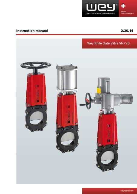
Wey <strong>Knife</strong> <strong>Gate</strong> Valve <strong>VN</strong> / <strong>VS</strong><br />
weyvalve.com
<strong>Instruction</strong> <strong>Manual</strong><br />
<strong>Wey®</strong> <strong>Knife</strong> <strong>Gate</strong> <strong>Valves</strong> <strong>VN</strong> / <strong>VS</strong><br />
1. GENERAL<br />
1.1 - Safety<br />
1.2 - Designated service, ATEX<br />
1.3 - Structure and function<br />
1.4 - Marking<br />
2. TRANSPORTATION, STORAGE<br />
2.1 - Transportation<br />
2.2 - Storage<br />
3. INSTALLATION<br />
3.1 - Preparation before installation<br />
3.2 - Installation site<br />
3.3 - Installation position<br />
3.4 - Flow and pressure direction<br />
3.5 - Mounting<br />
4. COMMISSIONING<br />
4.1 - General measures<br />
4.2 - Safety measures<br />
4.3 - Function test<br />
4.4 - Pneumatically operated valves<br />
4.5 - Hydraulically operated valves<br />
4.6 - Electrically operated valves<br />
5. MAINTENANCE<br />
5.1 - Inspection<br />
5.2 - Operating cycles<br />
5.3 - Repacking<br />
5.4 - Seal replacement<br />
5.5 - Cleaning / Lubrication<br />
6. TROUBLE SHOOTING<br />
7. REMOVAL<br />
8. DISPOSAL<br />
9. FINAL REMARKS<br />
Version 2012.04<br />
SISTAG AG, alte Kantonsstrasse 7, 6274 Eschenbach, Switzerland<br />
Telefon +41 (0)41 449 99 44, Telefax +41 (0)41 448 34 31 weyvalve.ch, info@weyvalve.ch
Wey � <strong>Knife</strong> <strong>Gate</strong> <strong>Valves</strong> <strong>VN</strong>/<strong>VS</strong> <strong>Instruction</strong> <strong>Manual</strong><br />
1. GENERAL<br />
1.1 Safety<br />
Prior to any work or start-up and in order to ensure a proper functioning of our products,<br />
The instruction manual must be observed.<br />
Alterations on the products need our written approval. For consequential damages due to<br />
neglect of this direction, we have to reject any liability.<br />
This symbol marks safety and risk advice. Follow all such advice in order to prevent any<br />
damage to human life and objects.<br />
The installation must be carried out according to established procedures and only by qualified<br />
personnel.<br />
Project related data of valves, e.g. dimensions, materials and service range are found in the<br />
respective documentation.<br />
The responsibility for the service application remains the sole duty of the end user.<br />
1.2 Designated service<br />
<strong>Wey®</strong> <strong>Knife</strong> gate valves are deigned to shut-off pressurized piping systems.<br />
Depending of the construction, finishing equipment and material valves can be used in fluid<br />
group 1 and 2 according to PED 97/23/EC up to category III.<br />
<strong>Wey®</strong> <strong>Knife</strong> gate valves may be installed as end-of-line service, provided that the valves are<br />
classified according to Art.3 (3) PED 97/23/EC. The max. working pressure must not exceed<br />
0.73-times of the max. nominal pressure at room temperature. In addition the chapter 3.5 must<br />
be considered.<br />
For the valve design working limitations refer to the relevant project data documentation and<br />
the maintenance manual.<br />
Should the Wey� knife gate valve be installed in an explosion-protected area, the valve and<br />
the electrical and non-electrical equipment must meet the explosion zone RL 94/9EG, ATEX<br />
1.3 Structure and function<br />
Version 2012.04 page 2 / 12<br />
1 Body with seal<br />
2 <strong>Gate</strong><br />
3 <strong>Manual</strong><br />
actuation<br />
4 Pneumatical<br />
actuation<br />
5 Electrical<br />
actuation<br />
6 Hydraulic<br />
actuation<br />
Fig. 1
Wey � <strong>Knife</strong> <strong>Gate</strong> <strong>Valves</strong> <strong>VN</strong>/<strong>VS</strong> <strong>Instruction</strong> <strong>Manual</strong><br />
1.4 Marking<br />
Manufacturer<br />
Type / Material<br />
Size / Flange drilling<br />
Year / Fabr. No.<br />
Nominal pressure.<br />
Operating pressure<br />
Medium temp.<br />
Ambient temp.<br />
Air supply pressure 1)<br />
Conformity / No notified body 1)<br />
1) if applicable<br />
2. TRANSPORTATION, STORAGE<br />
2.1 Transportation<br />
Version 2012.04 page 3 / 12<br />
Example<br />
Transportation of the valves to their final destination (building site) shall take place in solid<br />
crates adapted to the valves’ size. The valves shall be protected against exterior damage and<br />
atmospheric exposure.<br />
Depending on the duration of transportation or storage and in view of the conditions, preservation<br />
shall take place by welding valves into PE-film or adding sufficient drying agent or equal.<br />
2.2 Storage<br />
Until final installation the valves shall be stored in a dry, vented area. All function relevant<br />
parts shall be suitably covered against humidity, dust or other contamination.<br />
For longer storage periods or in case of unfavourable storage conditions which might affect<br />
later functioning, all blank surfaces, e.g. stem, piston rod, sealing surfaces shall be suitably<br />
protected by long-term preservatives against corrosion.<br />
Factory applied preservatives shall be checked for possible transport damages and<br />
appropriately repaired, if necessary.<br />
For accessories mounted to the valves, such as electric actuators, limit switches, solenoids,<br />
etc., the respective storage instructions of the manufacturer shall be observed with priority.<br />
3. INSTALLATION<br />
3.1 Preparation before installation<br />
Before installation, please make sure that the subject <strong>Wey®</strong> <strong>Knife</strong> gate valve is in<br />
conformance to the service conditions. The responsibility regarding applied service medium<br />
(corrosion resistance, pressure, temperature etc.) is with the end-user. Please check, if the<br />
valve to be installed in an explosion protected area, the valve meets the rules for the relevant<br />
zone.<br />
Not correctly aligned pipelines must, by all means, be corrected before installation in order to<br />
avoid tensions or even cracking of the valve body.<br />
Before final installation of the valves, any possibly applied corrosion protection shall be thoroughly<br />
removed. All parts, and in particular the gate, stem and piston rod shall be free of dust<br />
and dirt.
Wey � <strong>Knife</strong> <strong>Gate</strong> <strong>Valves</strong> <strong>VN</strong>/<strong>VS</strong> <strong>Instruction</strong> <strong>Manual</strong><br />
3.2 Installation site<br />
The mounting position must be chosen in such a way, that the knife gate valve can be<br />
checked and repaired at any time without risks.<br />
For repacking purpose the small side of the valve body shall be freely accessible (Fig. 2).<br />
� = Repacking feature Fig. 2<br />
Additional directives and guidelines for installation and operation of explosion protection<br />
equipment, when installed into Ex-zones, must also be observed.<br />
Check if the equipment fulfils the safety requirements at site.<br />
For outdoor installations, the valves shall be protected at site with shields or covers against<br />
severe weather conditions like snow and ice.<br />
3.3 Installation position<br />
<strong>Wey®</strong> <strong>Knife</strong> gate valves will be installed in one of the positions shown in fig.3. Avoid a<br />
different installation position whenever possible.<br />
Version 2012.04 page 4 / 12<br />
Fig. 3<br />
<strong>Wey®</strong> <strong>Knife</strong> gate valves from size DN400 up with extended or heavy actuators, which are not<br />
vertical installed, should be supported on site. This is also recommended, if vibrations of the<br />
piping line may occur.<br />
3.4 Flow and pressure direction<br />
The <strong>Wey®</strong> <strong>Knife</strong> gate valve is a bi-directional design (fig.4). Depending on applications and<br />
valve design options a preferred flow direction must be considered.
Wey � <strong>Knife</strong> <strong>Gate</strong> <strong>Valves</strong> <strong>VN</strong>/<strong>VS</strong> <strong>Instruction</strong> <strong>Manual</strong><br />
Liquid, gaseous and pneumatic conveyed solid fluids<br />
Flow direction Bi-directional possible (A,B)<br />
Version 2012.04 page 5 / 12<br />
With the application of a wear ring from the entry side (B)<br />
Pressure direction Against gate bevel preferred (A)<br />
Powder and granulate at gravity discharge<br />
(vertical piping)<br />
Flow direction<br />
Pressure direction<br />
The gate bevel is positioned on the descending side, also when a cone<br />
insert is used (B)<br />
The preferred pressure direction must especially be considered, if the valve is working at 60 –<br />
100% of the nominal pressure.<br />
A B<br />
1<br />
1 <strong>Gate</strong> bevel shape<br />
2 Wear ring (option)<br />
3 Cone insert / contracted bore (option)<br />
For difficult service conditions or for custom-made valves, please contact the manufacturer<br />
regarding the installation position.<br />
3.5 Mounting<br />
Before mounting, check valves for possible transportation or storage damages.<br />
The valves shall be protected against construction work at site.<br />
2<br />
Fig. 4<br />
For additional painting of the valves, the stem, piston rod, electric accessories and the valve<br />
gate protruding the body shall not be painted. Before any sand blasting, the valves shall be<br />
protected with covers.<br />
For valves with a stem extension, the pipeline flange must be exactly in line with the<br />
extension. The exact position of the flange holes in relation to the extension shall also be<br />
observed.<br />
<strong>Wey®</strong> <strong>Knife</strong> gate valves are installed between two piping flanges with thru bolts and with bolts<br />
for body blind holes.<br />
Piping system misalignments must never be corrected using the valve body. Tighten bolts with<br />
caution, so that tensions in the body do not cause any cracking or breaking. No tilting, steady<br />
crosswise tightening.<br />
Bolt torques are to be observed. Table 1<br />
B<br />
3<br />
1
Wey � <strong>Knife</strong> <strong>Gate</strong> <strong>Valves</strong> <strong>VN</strong>/<strong>VS</strong> <strong>Instruction</strong> <strong>Manual</strong><br />
Apply flange bolts according Fig. 5 into tapped blind holes.<br />
Pos. 1 Pos. 2 Pos. 3<br />
Pos. 1 : Wrong assembly<br />
Tightened bolts shall not touch the bottom of the tapped<br />
blind holes.<br />
Pos. 2 : Correct assembly<br />
Pos. 3 : Also correct assembly.<br />
Insert stud, then tighten nut.<br />
Pos. 4 Valve sizes DN80 – DN200 come with tapped thru holes<br />
in the chest area. Make sure to use the correct screw<br />
length. The screws must under no circumstance touch the<br />
gate as otherwise the gate will be blocked and damaged.<br />
Remaining flange holes to be applied with through bolts acc. Fig. 6<br />
Version 2012.04 page 6 / 12<br />
Pos. 4<br />
Fig. 5<br />
Mounting between flanges Mounting as head valve with<br />
counter-flange Fig.6<br />
The dimensions of the flange bolts, its number are found in the documentation.<br />
Size<br />
[mm]<br />
Bolt thread<br />
[mm]<br />
Torque<br />
[Nm]<br />
50-125 M16 60<br />
150-350 M20 120<br />
400-500 M24 220<br />
600-700 M27 320<br />
800-900 M30 440<br />
Table1 Torque for flange bolts<br />
Based upon type of flange gasket, manufacturer's<br />
instructions are to be observed. It is to ensure that the<br />
flange connection is tight. Leakage can be dangerous to<br />
humans and environment.<br />
When using bordering flanges special care applies. The flange face for type <strong>VN</strong>/<strong>VS</strong> have a<br />
reduced outside diameter compared with standard flanges. Therefore it is advisable to use<br />
rubber-steel-gaskets. Special care must be taken to ensure accurate centring of the gasket<br />
during installation.
Wey � <strong>Knife</strong> <strong>Gate</strong> <strong>Valves</strong> <strong>VN</strong>/<strong>VS</strong> <strong>Instruction</strong> <strong>Manual</strong><br />
If the <strong>Wey®</strong> <strong>Knife</strong> gate valves are installed as end-of-line service a counter-flange should be<br />
used. The chapter 1.2 must be considered. For an installation without counter-flange not all<br />
flange screws can be used. Due to this the nominal pressure reduction according to below<br />
table 2 applies. A rubber-steel-gaskets must be used.<br />
Table 2 Reduction of nominal pressure<br />
Body Material<br />
With counter<br />
flange<br />
Version 2012.04 page 7 / 12<br />
Without counter<br />
flange<br />
Cast steel 0.73 * PN 0.73 * PN<br />
Cast iron 0.73 * PN 0.50 * PN<br />
The installation as an end or head valve requires special attention. In service, the downstream<br />
side must not be accessible for persons. See also chapter 1.2 and 4.2.<br />
After installation a correct earthing connection must be verified. This is normally done through<br />
the flange bolt connection. If this is not the case, the potential or guard wire must be drawn to<br />
the terminal clamp.<br />
Should there be a longer time period between mounting and power connection of electrically<br />
operated valves, it shall be ensured that the integral heater of the actuator is already<br />
connected during mounting of the valves in order to avoid the formation of condensate water<br />
(or protect actuator with suitable drying agent).<br />
4. COMMISSIONING<br />
4.1 General measures<br />
Before taking the valves into service, all function relevant parts (gate, stem, piston rod, etc.)<br />
shall be thoroughly cleaned. Damages, in particular to the seal caused by remains of grit, welding<br />
beads, foreign rust or similar on the gate, are not covered by the warranty.<br />
For powder or granular service, it should be observed that wetted or humid media which has<br />
tendency to cake to the gate is thoroughly removed before start-up.<br />
The valves are factory preserved and lubricated for transportation and storage, but they<br />
require depending on the service conditions, another lubrication before start-up.<br />
Recommended are water-repellent, temperature resistant and long lasting lubricants. (Get<br />
your nearest supplier’s recommendation).<br />
4.2 Safety measures<br />
For automated valves installed in an area where valve movement could be dangerous for<br />
people (or animals/objects), it must be ensured by the user on-site that all moving parts are<br />
fenced with a suitable cover or protection shield.<br />
Should they not already be mounted, such covers are optionally available from manufacturer.<br />
Protection goals can also be reached through suitable on-site measure. Unprotected valves<br />
must not be commissioned.<br />
If hot gases or fluids are transported in the pipeline, ensure that no persons can touch the hot<br />
surfaces.<br />
It is also to ensure that no external interference of the control circuits can actuate the valve<br />
unintentionally.
Wey � <strong>Knife</strong> <strong>Gate</strong> <strong>Valves</strong> <strong>VN</strong>/<strong>VS</strong> <strong>Instruction</strong> <strong>Manual</strong><br />
4.3 Function Test<br />
Before commissioning a function test must be performed. Open and close the valve one time<br />
as a minimum.<br />
If the pipeline is pressure tested, it is to ensure that the applied pressure is not higher than the<br />
maximum allowed test pressure of the valve.<br />
4.4 Pneumatically operated valves<br />
Preventive measures must be taken, that the maximum tank pressure is not exceeding<br />
( 8 bar), also not in a breakdown situation.<br />
For operation of the actuator use only dry, filtered air acc. Class 4/5 ISO 8573-1<br />
max. dust particle size 40 µm<br />
max. dust particle concentration 10 mg/m3<br />
max. excess oil concentration 5 mg/m3<br />
pressure dew-point below minimal ambient temperature<br />
Solenoid valves shall be mounted as close as possible to the actuating cylinder.<br />
Air hoses, especially plastic pipes must be mounted and secured so that they cannot be<br />
unintentionally interrupted or torn. In order to keep a valve tight in its closed position, the piston<br />
must be permanently under pressure.<br />
The size of the air supply pipes has to be in relation to the air volume.<br />
Before start-up, all on-site mounted supply pipes and solenoid valves shall be thoroughly<br />
flushed and cleaned, if necessary.<br />
Factory mounted solenoid valves are normally provided without accessories like throttle or<br />
muffler. On-site regulations must therefore be observed.<br />
Pneumatically operated valves shall not be closed instantly in order to avoid the risk of<br />
pressure shocks.<br />
4.5 Hydraulically operated valves<br />
Before start-up, all on-site mounted supply pipes shall be thoroughly cleaned. Hydraulically<br />
actuated valves shall not be closed instantly in order to avoid the risk of pressure shocks.<br />
The maximum design air-supply pressure must not exceed. Higher air-supply pressure may<br />
damage the valve.<br />
4.6 Electrically actuated valves<br />
For electrical installations observe local rules, standards and directives.<br />
Additional directives and guidelines for installation and operation of explosion protection<br />
equipment, when installed into Ex-zones must also be observed.<br />
Check if the equipment fulfils the safety requirements at site:<br />
After installation a correct earthing connection must be verified. This is normally done through<br />
the flange bolt connection. If this is not the case, the potential or guard wire must be drawn to<br />
the terminal clamp.<br />
For trouble-free commissioning of electric actuators, we recommend to call on our specially<br />
trained customer service specialist.<br />
On-site electric installations shall be in accordance with respective connecting diagram of the<br />
supplier. In addition, the specific operating instructions of the actuator supplier shall be<br />
observed.<br />
Before the first electrical operation, the valve gate shall be set to an intermediate position with<br />
the manual override, and then started.<br />
When connecting to the power supply, the phase sequence has to be observed.<br />
Version 2012.04 page 8 / 12
Wey � <strong>Knife</strong> <strong>Gate</strong> <strong>Valves</strong> <strong>VN</strong>/<strong>VS</strong> <strong>Instruction</strong> <strong>Manual</strong><br />
With wrong phase sequence, limit and torque switches are ineffective.<br />
The switch off-shall be in accordance to our instructions/diagrams, i.e.:<br />
- Switch-off in closing direction: usually by limit switches, exceptionally by torque<br />
- Switches (for abrasive service applications).<br />
- Switch-off in opening direction: by limit switches only, as the torque switch serves<br />
as overload protection.<br />
5. MAINTENANCE<br />
5.1 Inspection<br />
When in operation with dangerous fluids especially the leak-tightness against atmospheric<br />
area must be controlled on a regular basis. At possible indication of leakage must be<br />
repacked.<br />
5.2 Operating cycles<br />
During one service year, at least four (4) operating cycles shall take place, whereby all<br />
components shall be checked. Under severe service conditions, such functional checks shall<br />
take place more frequently.<br />
5.3 Repacking<br />
During a longer storage period of the <strong>Wey®</strong> <strong>Knife</strong> gate valves or in case of great temperature<br />
fluctuations, the packing material in the transverse seal may shrink. This could lead to slight<br />
leakage through the transverse seal in the body chest area.<br />
Should a leakage be detected at the transverse seal which remains even after repeated actuation<br />
of the gate, the valve can be repacked easily and quickly while installed. During this work<br />
however, the valve should possibly not be under full service pressure.<br />
Mostly, it is only necessary to firmly tighten the four (4) packing screws on the side by 1-2<br />
turns.<br />
Did the leakage not stop (after packing screws are fully tightened), then remove the screws<br />
from the valve body (Fig. 7)<br />
Insert packing pellet into holes and compress firmly with packing tool. Repeat until valve is<br />
absolutely tight.<br />
Please observe that the valve gate is not pressed against the valve body due to the repacking.<br />
One-sided and too powerful repacking can cause the valve gate to jam.<br />
Version 2012.04 page 9 / 12<br />
Repacking tool<br />
Repacking screw<br />
Seal cartridge<br />
Fig. 7
Wey � <strong>Knife</strong> <strong>Gate</strong> <strong>Valves</strong> <strong>VN</strong>/<strong>VS</strong> <strong>Instruction</strong> <strong>Manual</strong><br />
5.4 Seal replacement<br />
Should a leakage through the bore passage occur, the cause is mostly damage or wear of the<br />
body seal.<br />
The valve body seal can only be replaced when the valve is removed from the pipeline.<br />
Seal replacement can be performed by trained personnel according instructions or at any time<br />
in our works.<br />
5.5 Cleaning / Lubrication<br />
Stem rods, pull and piston rods shall be free of dirt and contamination and shall always be well<br />
lubricated.<br />
Lubrication points on handwheel bearings shall be regularly lubricated based on the operating<br />
conditions, but at least every 3 months.<br />
Pneumatic cylinders with closing cushion are fitted with a self-lubricating rod seal.<br />
Any leakages on the cylinders require the exchange of all sealing components.<br />
For valves with electric actuators, the lubrication point on the drive should be especially<br />
observed.<br />
The respective operating instructions of the actuator supplier are binding.<br />
Depending on the service conditions of the valves, the gate is to clean and needs possibly<br />
slight lubrication.<br />
Version 2012.04 page 10 / 12
Wey � <strong>Knife</strong> <strong>Gate</strong> <strong>Valves</strong> <strong>VN</strong>/<strong>VS</strong> <strong>Instruction</strong> <strong>Manual</strong><br />
6. TROUBLE SHOOTING<br />
Trouble Possible Cause Elimination<br />
Leakage at gate in<br />
body chest area.<br />
Leakage in bore<br />
passage of valve<br />
Leakage through valve<br />
body halves<br />
Valve gate is not<br />
movable<br />
Closing or opening<br />
stroke ceasing or<br />
stagnating<br />
Pressure loss on supply<br />
net<br />
Version 2012.04 page 11 / 12<br />
Transverse seal untight Repacking of transverse seal according to instructions<br />
Transverse seal damaged Replacement of transverse seal according to instructions,<br />
cleaning of valve gate, if necessary replacement of gate<br />
Valve gate not completely closed;<br />
jammed particles between gate<br />
and body internals<br />
Jammed particles between stem<br />
nut, resp. clevis and body chest<br />
<strong>Manual</strong> valves:<br />
- Open valve slightly and repeat closing action<br />
- Remove jammed particles<br />
Pneumatically and hydraulically operated valves:<br />
- Open valve slightly and repeat closing action<br />
- Check, if necessary new setting of clevis, resp. stroke<br />
- Remove jammed particles<br />
Electrically actuated valves:<br />
- Open valve slightly and repeat closing action, check,<br />
possibly reset switches (upon supplier’s<br />
recommendation)<br />
- Remove jammed particles<br />
Body seal damaged Remove valve, replace seals according to instructions<br />
Valve distorted during mounting Untighten flange bolts and re-tighten according to<br />
instructions<br />
Sealant between body halves<br />
damaged<br />
Actuating components damaged <strong>Manual</strong> valves:<br />
Valve clogged; Valve gate<br />
contaminated<br />
Remove valve and replace sealant according to instructions<br />
- Check, clean stem or stem nut, replace if necessary,<br />
lubricate<br />
Pneumatically and hydraulically operated valves:<br />
- Check supply pressure Check if current onto solenoid<br />
exists. Check solenoid for damages Check hydraulic<br />
cylinder for damages (seal)<br />
- Clean and lubricate; if necessary replace damaged<br />
components acc. to supplier’s instructions<br />
Electrically actuated valves:<br />
- Check if current exists<br />
- Check if motor defect<br />
- Check if limit switches defect or adjusted<br />
- Check if gear, stem or stem nut damaged<br />
- Clean and lubricate; if necessary replace damaged<br />
components acc. to supplier’s instructions<br />
Remove valve, clean, possibly disassemble completely<br />
Insufficient supply pressure Pneumatically and hydraulically operated valves:<br />
Check supply pressure, possibly increase supply pressure<br />
Solenoid valve dirty Remove and clean solenoid valve, possibly install filter<br />
Piston rod seal damaged Remove and clean piston rod seal, exchange and lubricate<br />
cylinder seals<br />
Valve clogged Clean valve and lubricate<br />
Control pipe connection damaged Check pipe connections, tighten, replace if necessary<br />
Cylinder seals damaged - Check and replace cylinder seals, lubricate<br />
- Check piston rod seal, clean, lubricate
Wey � <strong>Knife</strong> <strong>Gate</strong> <strong>Valves</strong> <strong>VN</strong>/<strong>VS</strong> <strong>Instruction</strong> <strong>Manual</strong><br />
7. REMOVAL<br />
Before removing the valve, consider that the pipe system can be under pressure and that<br />
hazardous media could get into the environment. Respective precaution measures must be<br />
taken.<br />
Actuators must, in principle, not be removed if pipeline system is under pressure. Electric<br />
actuators must be made current less, respectively disconnected from circuit.<br />
Pneumatic and hydraulic actuators must be pressure less and disconnected from supply lines.<br />
In case the pipe is removed on one side only, ensure before that the valve cannot be operated.<br />
Unintentional opening of the valve can be hazardous to people and environment due to drain-off<br />
of service medium. Unintentional closing can be very harmful, if a person (or body part) is within<br />
the area of the valve gate travel.<br />
8. DISPOSAL<br />
Observe that sediments inside of valve or pipe can be harmful to people and environment.<br />
Respective precautions measures are to be taken. After finished service life the valve must be<br />
disposed skilful and in conformity with environmental regulations.<br />
9. FINAL REMARKS<br />
All details given above are to our current up-to-date knowledge and shall provide, together<br />
with our technical documentation, information about our products and their range of<br />
applications.<br />
They are not thought to assure particular features of the products nor their suitability for a<br />
specific application.<br />
Faultless quality is assured within our General Sales Conditions.<br />
For any further information, please call any time on our Customer Service Department.<br />
Alterations reserved<br />
Version 2012.04 page 12 / 12