

Triskelion Ultra Precision Tactile Probe System - Ibs precision ...
Triskelion Ultra Precision Tactile Probe System - Ibs precision ...
Triskelion Ultra Precision Tactile Probe System - Ibs precision ...

Create successful ePaper yourself
Turn your PDF publications into a flip-book with our unique Google optimized e-Paper software.
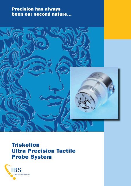
<strong>Precision</strong> has always<br />
been our second nature...<br />
<strong>Triskelion</strong><br />
<strong>Ultra</strong> <strong>Precision</strong> <strong>Tactile</strong><br />
<strong>Probe</strong> <strong>System</strong>
<strong>Triskelion</strong> | <strong>Ultra</strong> <strong>Precision</strong> <strong>Tactile</strong> <strong>Probe</strong> <strong>System</strong><br />
1.1 Introduction<br />
IBS <strong>Precision</strong> Engineering has developed an new ultra-<strong>precision</strong> touch probe system, the <strong>Triskelion</strong><br />
probe. This probe system is suitable for point measurements as well as scanning. Its excellent measuring<br />
uncertainty and full 3D measurement capabilities make this probe suitable for ultra-<strong>precision</strong> 3D<br />
metrology. Possible applications include 3D ultra-<strong>precision</strong> (micro-/nano-) CMMs as well as on-machine<br />
metrology on machine tools.<br />
1.2 <strong>Probe</strong> concept<br />
A schematic representation of the probe concept is shown in figure 1.1. The stylus is elastically<br />
suspended by means of flexures. The stylus is a attached to these flexures via a rigid body; this body<br />
contains target discs which serve as measurement targets for the capacitance sensors. During deflection<br />
of the probe tip, the capacitance sensors measure the displacements of these target discs; the<br />
displacement of the probe tip can thus be determined.<br />
Capacitance sensor<br />
<strong>Probe</strong> housing<br />
Flexure<br />
Target disc<br />
Stylus<br />
Work piece<br />
Figure 1.1: Schematic representation of probe concept<br />
Figure 1.1 shows the working principle of the probe system for deflection of the probe tip in vertical and<br />
sideways direction. Note that this is a 2D simplification, the actual design features three flexures and<br />
three capacitance sensors, allowing deflection in full 3D, while the deflection of the tip is also measured<br />
in x-, y- and z-direction.<br />
The suspension of the stylus is realized by means of a monolithic metal suspension foil. This foil contains<br />
both the flexures and the three-legged body which connects the flexures to the stylus. The thickness of<br />
the flexures is reduced to achieve the desired (low) stiffness of the suspension and to ensure that elastic<br />
deformation takes place in the flexures and not in the three-legged body or in the stylus. At the end of<br />
each flexure, circular target discs serve as the targets for the three capacitance sensors.<br />
Figure 1.2 shows a CAD model of the realized probe-system. For this design, a stylus length of 8.5 mm is<br />
applied, with a Ø 0.5 mm spherical ruby probe tip. The following section will discuss the most important<br />
design features of the realized probe system.<br />
<strong>Probe</strong> housing<br />
Monolithic flexure foil<br />
Target disc for<br />
capacitive sensor(3*)<br />
Three-legged<br />
stiff body<br />
Stylus and probe tip<br />
z<br />
x<br />
Figure 1.2: Design of the <strong>Triskelion</strong> ultra-<strong>precision</strong> touch probe.<br />
European Centre of Excellence in Metrology<br />
y<br />
ø 35 mm.<br />
1 connector for 3 probes
1.3 Design features<br />
1.3.1 Low contact force<br />
When the contact force between probe tip and work piece surface is too high, there may be a risk of<br />
damaging the surface. For the probe design shown in figure 1.2, this contact force is limited by selecting<br />
a sufficiently low stiffness for the suspension of the stylus. A stiffness of 70 N/m was realized, which<br />
results in a typical probing force of 0.5 mN or less.<br />
1.3.2 Low collision force<br />
Other than the ‘static’ contact force, the impact of the probe tip colliding with the work piece can also<br />
cause surface damage. Although this can be reduced by applying low probing velocities, this is generally<br />
not desired as measurement times may increase.<br />
A more efficient way to reduce the collision force is to minimize the suspended mass of the system. For<br />
the probe system discussed here, the suspended mass was reduced to 160 mg.<br />
1.3.3 Large measurement range<br />
The measurement range of the probe system is a critical parameter for the control of the CMM: after a<br />
probe trigger has been detected, the CMM axes should reach a standstill within the measuring range<br />
of the probe system. If this is the case, simply adding the measured probe deflection to the position<br />
measurements from the machine axes will yield the measurement point coordinates. The measurement<br />
range of the new probe system is more than 10 µm in all directions.<br />
1.3.4 <strong>Probe</strong> tip size<br />
The long-term stability of the probe system has been optimized by applying low-expansion materials. The<br />
complete probe body and the elastic suspension are made from invar®. The stylus is made from tungsten<br />
carbide. In addition, the probe system is assembled from only a minimum number of parts, without<br />
adhesives or other potentially instable assembly techniques.<br />
1.3.5 Low replacement costs<br />
Products may have small features, such as narrow ridges or small holes, which cannot be measured with<br />
a large probe tip. Reducing the probe tip size greatly increases the measurable area of such work pieces.<br />
For this probe system, spherical ruby tips with radii between 0.08 and 0.25 mm can be applied.<br />
IBS <strong>Precision</strong> Engineering is currently developing a miniaturized version of the <strong>Triskelion</strong> probe system,<br />
which has a spherical tip with a radius of only 36 µm.<br />
1.3.6 Robust design and low replacement costs<br />
As the suspension of the probe is made from metal, the probe system is quite robust and will not break<br />
upon touch.<br />
The most expensive part of the probe is the measurement system; because the three capacitance<br />
sensors can be re-used, even when the more fragile parts of the probe system have been damaged,<br />
replacement costs of a damaged probe are relatively low.<br />
2. Calibration and application<br />
Figure 2.1 shows some results of the sensitivity<br />
calibration of the probe system, which give a good<br />
indication of the measurement uncertainty of the<br />
measured probe deflection. The measurement result<br />
presented here shows the measurement errors in 3D<br />
for a tip deflection up to 5 µm.<br />
European Centre of Excellence in Metrology<br />
Figure 2.1: 3D Measurement errors for probe tip deflection up to 5µm
05-10<br />
Figure 2.2 shows a photograph of the probe system<br />
during measurement of an aspherical mould insert.<br />
For this measurement, the probe system was<br />
integrated in an ultra-<strong>precision</strong> CMM. The form error<br />
of the measured mould insert is also shown; this<br />
is the residual after subtraction of the theoretical<br />
asphere. No data filtering was applied.<br />
Residual form error of measured profile<br />
3. Summary<br />
The design characteristics of the pre-prototype are summarized in the table below.<br />
Tip diameter<br />
Stylus length<br />
<strong>Probe</strong> housing diameter<br />
Suspended mass<br />
<strong>Probe</strong> stiffness (at tip)<br />
Measurement range X, Y<br />
Measurement range Z<br />
Measurement resolution<br />
3D Measurement uncertainly of<br />
tip deflection (k=2)<br />
*Other stylus lengths and tip sizes are available upon request.<br />
IBS <strong>Precision</strong> Engineering Deutschland GmbH<br />
Leitzstraße 45, 70469 Stuttgart, Germany<br />
Telephone: +49 (0)711 490 66 230<br />
Fax: +49 (0)711 490 66 232<br />
E-mail: info@ibspe.de, Internet: www.ibspe.de<br />
Parameters of realized<br />
<strong>Triskelion</strong> probe<br />
0.5 mm*<br />
8.5 mm*<br />
35 mm<br />
160 mg<br />
70 N/m isotropic<br />
± 10 µm<br />
± 10 µm<br />
3 nm<br />
< 15 nm<br />
Table 3.1: Design parameters of realized ultra-<strong>precision</strong> probe system<br />
<br />
Figure 2.2: Measurement of aspherical mould insert<br />
HEADOFFICE | IBS <strong>Precision</strong> Engineering bv<br />
Industrial area Esp 201, 5633 AD Eindhoven, The Netherlands<br />
Telephone: +31 (0)40 290 12 70<br />
Fax: +31 (0)40 290 12 79<br />
E-mail: info@ibspe.com, Internet: www.ibspe.com<br />
IBS <strong>Precision</strong> Engineering sarl<br />
Le Magellan, 7 rue Montespan, 91024 EVRY CEDEX, France<br />
Telephone: +33 (0)1 69 47 60 53<br />
Fax: +33 (0)1 69 47 60 70<br />
Parameters of <strong>Triskelion</strong><br />
miniaturized-probe<br />
0.07 mm<br />
6 mm<br />
20 mm<br />
75 mg<br />
XY: 13 N/m<br />
Z: 20 N/m<br />
± 10 µm<br />
± 10 µm<br />
3 nm<br />
< 20 nm<br />
E-mail: info@ibspe.fr, Internet: www.ibspe.fr