Operating instructions Gen.2 - SEITZ - valve technology
Operating instructions Gen.2 - SEITZ - valve technology
Operating instructions Gen.2 - SEITZ - valve technology

Create successful ePaper yourself
Turn your PDF publications into a flip-book with our unique Google optimized e-Paper software.
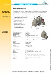
Original operating <strong>instructions</strong> <strong>SEITZ</strong> TopValve CNG<br />
Types 2506, 2546, 2586, 2649, 2682, 2715<br />
Translation of Original <strong>Operating</strong> <strong>instructions</strong><br />
Table of Contents<br />
1 Safety Instructions<br />
2 Intended Use<br />
3 Warranty<br />
4 Technical Data<br />
5 Solenoids<br />
6 Sectional view<br />
7 Functional Description<br />
8 Installation and Commissioning/Operation<br />
9 Maintenance<br />
9.1 General<br />
9.2 Removal<br />
9.3 Servicing Tasks<br />
9.4 Installation<br />
9.5 Function Check/Test<br />
10 Procedure for Malfunctions<br />
11 Decommissioning<br />
12 Disposal<br />
13 Tables<br />
14 Conformity Declaration<br />
15 Addresses<br />
Explanation of symbols<br />
Attention<br />
Read instruction<br />
Danger to life<br />
Danger of explosion<br />
Hot or cold surfaces<br />
Safety goggles and ear protection<br />
Disposal<br />
© EUGEN <strong>SEITZ</strong> AG 2011 D E F I SP Item No. 238.727.01 Printed in Switzerland 0711/5.0 Subject to technical changes and changes in the scope of delivery.
We thank you very much for purchasing this product and, thus, the vested confidence.<br />
In order to ensure safe and trouble-free function, these operating <strong>instructions</strong> must be strictly adhered to. The<br />
user must ensure that the specified conditions for use and performance data of the device are adhered to, as well as<br />
the country-specific statutory regulations. The manufacturer accepts no liability for this. These operating <strong>instructions</strong><br />
are a constituent part of the product and are to be accordingly integrated into the system operating <strong>instructions</strong> or<br />
machine description. We reserve the right to make modifications for the means of further technical development.<br />
1 Safety Instructions<br />
Authorized Persons<br />
The tasks described here must only be carried out by authorized and trained persons. Authorized persons are those<br />
who possess sufficient knowledge about gases in conjunction with high pressure and who can also verify skills for<br />
installation. The facility operator is responsible for naming, instructing and regularly checking the person deemed to be<br />
authorised.<br />
General Hazard Instructions<br />
ATTENTION DANGER TO LIFE!<br />
Gases compressed to high pressure possess a large energy potential and, thus, great dangers.<br />
INCORRECTLY ASSEMBLED COMPONENTS CAN EXPLOSIVELY DISTRIBUTE THEMSELVES AND FATALLY<br />
INJURE HUMANS.<br />
Leakage of combustible gases can result in explosions or asphyxiation.<br />
Icing is an indication of escaping gas. Do not touch frosted system components, danger of frostbite. Dissipate<br />
pressure and rectify leakage.<br />
Before starting tasks on high-pressure <strong>valve</strong>s, make sure that the gas system is depressurized and secured<br />
against unauthorized charging. The subsequent recommissioning / pressurizing must be carried out by authorized<br />
persons with specialist knowledge. Depletion of the gas system must not be carried out by releasing bolts or<br />
connections, but only through the draining facilities provided.<br />
Strictly adhere to the specified tightening torques, refer to Table 1. Non-adherence to the tightening torques<br />
can result in leakage, damage and failure of pressurized components.<br />
If damaged components are detected, the <strong>valve</strong> must be depressurized and the damaged components<br />
replaced. The <strong>valve</strong> must only be pressurized when fully installed.<br />
After the system has been ventilated or depressurized, flushing using inert gas must be carried out.<br />
Pressurization must be carried out slowly. Pressurizing quickly can result in ignition of the remaining gas-air mixture<br />
and destruction of the system components.<br />
2 Intended Use<br />
These operating <strong>instructions</strong> are applicable to Eugen Seitz high-pressure solenoid <strong>valve</strong>s of the product family<br />
TopValve, for use at filling stations for Compressed Natural Gas (CNG).<br />
Attention: Observe the approved pressure and temperature range on the name plate. Media: Natural gas in<br />
accordance with DIN 51624 and inert gases that is not aggressive to housing and sealing materials. If in doubt,<br />
contact the manufacturer.<br />
Using media that is not approved can result in failure, destruction or bursting of the <strong>valve</strong>.<br />
Contamination in the pipelines can impair the function of the <strong>valve</strong>. In order to ensure the longest possible service life,<br />
we recommend installing suitable filters.
3 Warranty<br />
The contractually agreed warranty conditions apply. In the absence of contractual warranty conditions, the legal notice<br />
with the following consideration is applicable. Trouble-free operation of the high-pressure solenoid <strong>valve</strong>s is only<br />
ensured when the following points are adhered to:<br />
The <strong>valve</strong> is only designed for operation using CNG and inert gas. It must not be pressurized using liquids.<br />
It should be installed within an enclosed housing or in buildings, direct exposure to the weather must be avoided.<br />
Observe the direction of flow.<br />
The <strong>valve</strong> has seals that are subject to wear during operation. In order to ensure trouble-free operation, a regular<br />
function and leak check of the <strong>valve</strong>s must be carried out and, as required, serviced using the Eugen Seitz AG original<br />
repair kit or replaced.<br />
4 Technical Data<br />
Pressure range: 1 – 35 MPa (10 – 350 bar)<br />
Test pressure: 52.5 MPa (525 bar)<br />
Temperature range: -20...+60°C<br />
Nominal diameter: DN0.8, DN12, DN18, DN25<br />
Application: Natural gas in accordance with DIN 51624<br />
Quality of gas: In accordance with ISO 8573-1<br />
Leakage: < 0.12 Nl/h<br />
5 Solenoids<br />
The reliable function of the <strong>valve</strong> can only be ensured by a recommended solenoid from the company Eugen Seitz AG<br />
and under consideration of the enclosed "<strong>Operating</strong> <strong>instructions</strong> for solenoids".<br />
6 Sectional view<br />
Type 2506 Type 2546
Type 2586 Type 2715<br />
Type 2649 Type 2682<br />
Positions indicated * are replaceable parts included in the original repair kit.<br />
7 Functional Description<br />
The <strong>valve</strong>s 2546, 2586, 2649 and 2715 are inherent medium - pilot operated 2/2-way solenoid <strong>valve</strong>s. They are closed<br />
under spring pressure when deenergized, but open with pressure reversal, as non-return <strong>valve</strong>s. If flow should be<br />
prevented with pressure reversal, an additional non-return <strong>valve</strong> must be provided.<br />
By a rapid increase in pressure at the <strong>valve</strong> inlet, the deenergized <strong>valve</strong> momentarily opens until pressure equalization<br />
occurs in the <strong>valve</strong> and the piston again closes. This characteristic is system-dependent and normal.<br />
In contrast to the types mentioned above, the <strong>valve</strong> types 2506 and 2682 are open when deenergized. They close<br />
when the solenoid is activated.<br />
Furthermore, the <strong>valve</strong> type 2682 is a direct-acting 2/2-way solenoid <strong>valve</strong>.
Type 2546, 2586, 2715 Type 2506 Type 2682<br />
Type 2649<br />
8 Installation and Commissioning/Operation<br />
Purge all lines using inert gas before the initial commissioning and carrying out servicing tasks. Absolute cleanliness is<br />
required. Particles of dirt can cause malfunctions. Contamination ≥ 40µm must be filtered out. (Particle in accordance with<br />
ISO8573.1, Qual. 5/ pressure dewpoint in accordance with ISO8573.1, Qual. 3/ oil content ISO 8573.1, Qual. 3).<br />
Installation position is arbitrary. It is recommended to install with the solenoid upwards. Observe the direction of flow.<br />
The <strong>valve</strong> is delivered checked and ready to install. It must be adequately attached in the system, subsequently, the<br />
gas and electrical connections must be connected.<br />
The specified tightening torques must be adhered to when tightening all fittings, refer to Table 1.<br />
Subsequently, check the leak tightness of the connections by carrying out a test for external leakage at the rated<br />
pressure and with the <strong>valve</strong> open.<br />
Wear ear protection and safety goggles!<br />
If a leakage test is carried out at a rated pressure of 1.5, it is imperative to keep the <strong>valve</strong> in the open position,<br />
in order to prevent damage to the piston. For this, the solenoid must be energized.<br />
The leak test must only be carried out using specified agents for this purpose in accordance with Table 2, or<br />
an equivalent agent. Other foaming agents can result in corrosion and material embrittlement and cause a hazard<br />
through failure, for example because of the chlorine content.<br />
If other pressure devices be connected to the <strong>valve</strong>s described in these operating <strong>instructions</strong>, the respective<br />
applicable operating <strong>instructions</strong> of the other pressure devices must also be taken into consideration.
9 Maintenance<br />
9.1 General<br />
Before begriming tasks described here, the following chapters must be read and taken into consideration:<br />
• Safety Instructions<br />
• Warranty<br />
• Function Description<br />
• Procedure for Malfunctions<br />
For each type of <strong>valve</strong>, an original repair kit is available from Eugen Seitz AG. An overview can be found on our<br />
Internet page: www.seitz.ch/de/afs/cng/maintenance.php<br />
The safety and leak tightness can only be ensured using original parts from Eugen Seitz AG.<br />
Repairs on individual parts must not be carried out. Worn or defective parts must be replaced by new original<br />
parts from Eugen Seitz AG.<br />
If in doubt, send the <strong>valve</strong> to our repair service, or inform our service department.<br />
9.2 Removal<br />
1. Switch off the power and dissipate the pressure.<br />
2. Release the SW22 nut, remove the serrated washer and solenoid.<br />
3. Release the bolts Pos. 82, flange Pos. 81 and remove the guide tube Pos. 33.<br />
4. Release the bolts Pos. 11 (for Type 2649 also Pos. 87). Remove the cover Pos. 02.<br />
For Type 2682 Step 4 not applicable.<br />
9.3 Servicing Tasks<br />
Use a neutral cleaning agent and not an abrasive agent to clean all components. Thereby, pay attention to soiling in<br />
the gas system (oil, water, particles) and rectify cause. Check the <strong>valve</strong> seat in the housing for damage.<br />
Install the new components from the original repair kit. Use grease and lightly lubricate the seals and bearing<br />
surfaces. Recommended grease: SIL-JET-Spray.<br />
9.4 Installation<br />
The following is applicable in general: All tightening torques for bolts and pipe fittings at the inlet and outlet, in<br />
accordance with Table 1: Adhere to "Tightening torques".<br />
1. Install all O-Ring seals (use an approved grease to lightly lubricate, refer to Table 3).<br />
2. Insert the piston cpl. Pos. 78 with spring Pos. 92 in the cover Pos. 02.<br />
3. Insert the piston Pos. 04, together with spring Pos. 68, in the cover Pos. 02. Install the cover on the housing Pos.<br />
01.<br />
4. Hand tighten the bolts Pos. 11 (for Type 2649 also Pos. 87) diagonally, subsequently, use a torque wrench and<br />
tighten diagonally.<br />
5. Put the pin Pos. 14 (Pos. 28 for Type 2682), together with the spring Pos. 54, in position in the anchor cpl. Pos. 30<br />
and insert into the guide tube Pos. 33. Together with the flange Pos. 81 install in the cover Pos. 02 (housing Pos. 01<br />
for Type 2682).<br />
6. Hand tighten the bolts Pos. 82 diagonally, subsequently, use a torque wrench and tighten diagonally.<br />
7. Install the solenoid, serrated washer and hand tighten the nut SW22.<br />
8. Install the screw connections G (flat sealing) or SAE (O-Ring sealed on chamfers at the input) in accordance<br />
with Table 1 "Tightening torques"!<br />
For Type 2682 Steps 2 to 4 not applicable.<br />
For Type 2506 Step 5 not applicable.
9.5 Function Check/Test<br />
After opening the <strong>valve</strong> for maintenance, proceed as follows:<br />
1. Flush using inert gas.<br />
Attention: Pressurization must be carried out slowly. Pressurizing quickly can result in ignition of the remaining<br />
gas-air mixture and destruction of the system components.<br />
2. Increase the pressure at the <strong>valve</strong> inlet to 20 bar.<br />
3. Electrically energize 2 to 5 times. The <strong>valve</strong> must audibly switch.<br />
4. Increase the pressure to a min. 120 bar. (Pressure differential: <strong>valve</strong> inlet to <strong>valve</strong> outlet min. 120 bar).<br />
5. Electrically energize 2 to 5 times. The <strong>valve</strong> must audibly switch.<br />
6. Leave pressure at min. 120 bar and check for leakage externally. Using an approved leak detector spray (refer to<br />
Table 2) put foam at all joints, screw connections and closed bores of the complete <strong>valve</strong>. There must be no visible<br />
sign of bubbles.<br />
10 Procedure for Malfunctions<br />
Attention: Wear ear protection and safety goggles if components of the system are pressurized!<br />
Only switch the pressurized <strong>valve</strong> when there is no hazardous conditions!<br />
- Check the connections, electrical voltage and function of the solenoid<br />
- Check to make sure that the <strong>valve</strong> pressurizes<br />
- If the problems remain, dissipate the pressure and examine the <strong>valve</strong> in accordance with the <strong>instructions</strong>.<br />
Thereby, pay attention to soiling in the gas system (oil, water, particles) and rectify cause.<br />
- If installed, check the filter for soiling<br />
- If there is icing on the <strong>valve</strong>, slowly warm until at room temperature. Avoid abrupt temperature shocks.<br />
If you cannot rectify the malfunction, return the <strong>valve</strong> to Eugen Seitz for inspection.<br />
11 Decommissioning<br />
1. Switch off the power and dissipate the pressure.<br />
2. Remove the <strong>valve</strong>.<br />
12 Disposal<br />
Observe the respective country-specific environmental legislations. As far as possible, the individual<br />
components must be fed to the recycling process.<br />
13 Tables<br />
Table 1: Tightening torques<br />
Type Nominal dia. Screw connection
Table 2: Approved leak detection agent<br />
Bezeichnung = Designation<br />
Using other foaming agents can result in corrosion and material embrittlement and cause a hazard through failure, for<br />
example because of the chlorine content.<br />
Table 3: Approved lubricants<br />
Using other lubricants can result in corrosion and material embrittlement and cause a hazard through failure, for<br />
example because of the chlorine content.<br />
14 Conformity Declaration<br />
EC Conformity Declaration in accordance with Appendix VII of the Directive 97/23/EU.<br />
15 Addresses<br />
Eugen Seitz AG<br />
Spitalstrasse 204<br />
8623 Wetzikon<br />
Switzerland<br />
+41 44 931 80 80<br />
info@seitz.ch<br />
www.seitz.ch<br />
Eugen Seitz GmbH<br />
Beindersheimer Strasse 46<br />
67227 Frankenthal<br />
Germany<br />
+49 6233 35 61 11<br />
info@eugenseitz.de<br />
Eugen Seitz Shanghai<br />
Xinjian Rd. No.58-2<br />
Green land Tech. Island A<br />
Shanghai 201199<br />
China<br />
+86 21 3363 3880<br />
information@seitz.cn<br />
Eugen Seitz Middle East<br />
Dubai Airport Freezone<br />
Office no 4WA G05<br />
Dubai<br />
UAE<br />
+971 4 260 2031