Performance Analysis and Simulation of Cyclic Code-Shift Keying
Performance Analysis and Simulation of Cyclic Code-Shift Keying
Performance Analysis and Simulation of Cyclic Code-Shift Keying

Create successful ePaper yourself
Turn your PDF publications into a flip-book with our unique Google optimized e-Paper software.
<strong>Performance</strong> <strong>Analysis</strong> <strong>and</strong> <strong>Simulation</strong> <strong>of</strong> <strong>Cyclic</strong><br />
<strong>Code</strong>-<strong>Shift</strong> <strong>Keying</strong><br />
Abstract—<strong>Cyclic</strong> code-shift keying (CCSK) is the baseb<strong>and</strong><br />
symbol modulation scheme used by Joint Tactical Information<br />
Distribution System (JTIDS), the communication terminal <strong>of</strong><br />
Link-16. Since CCSK is non-orthogonal, an analytic evaluation <strong>of</strong><br />
its performance in terms <strong>of</strong> probability <strong>of</strong> symbol error is<br />
nontrivial. In this paper, an analytic upper bound on the<br />
probability <strong>of</strong> symbol error <strong>of</strong> CCSK is derived for the 32-chip<br />
CCSK sequence chosen for JTIDS. The probability <strong>of</strong> symbol<br />
error obtained with the analytic method is compared with that<br />
obtained by Monte Carlo simulation for additive white Gaussian<br />
noise. The results show that the analytic method yields a tight<br />
upper bound. In addition to the 32-chip CCSK sequence chosen<br />
for JTIDS, a new 32-chip CCSK sequence with a smaller<br />
maximum <strong>of</strong>f-peak cross-correlation is obtained <strong>and</strong> evaluated<br />
both analytically <strong>and</strong> by Monte Carlo simulation. The results<br />
obtained for the new CCSK sequence compare favorably with the<br />
sequence chosen for JTIDS.<br />
Index Terms—cyclic code-shift keying (CCSK), Joint Tactical<br />
Information Distribution System (JTIDS), Link-16, probability<br />
<strong>of</strong> symbol error.<br />
I. INTRODUCTION<br />
yclic code-shift keying (CCSK) is the baseb<strong>and</strong> symbol<br />
Cmodulation<br />
scheme used by Joint Tactical Information<br />
Distribution System (JTIDS), the communication terminal <strong>of</strong><br />
Link-16. Based on a time-division multiple access<br />
architecture, Link-16 provides a secure <strong>and</strong> ostensibly jamresistant<br />
data link so that near real-time tactical information<br />
can be exchanged among different platforms. JTIDS is<br />
essentially a hybrid direct sequence/frequency-hopping<br />
(DS/FH) spread spectrum system that uses a (31,15) Reed-<br />
Solomon code for forward error correction coding, CCSK for<br />
baseb<strong>and</strong> symbol modulation, <strong>and</strong> minimum-shift keying<br />
(MSK) for chip modulation. The performance <strong>of</strong> hybrid<br />
DS/FH spread spectrum systems with various modulation<br />
schemes in different types <strong>of</strong> interference <strong>and</strong> fading has been<br />
investigated in [1]-[5], but only [2] attempts to evaluate the<br />
performance <strong>of</strong> JTIDS’s waveform analytically in additive<br />
white Gaussian noise (AWGN). However, the results<br />
presented in [2] are based on the overly optimistic assumption<br />
that the cross-correlation values for the CCSK symbol<br />
demodulator are independent. Actually, it can be shown that<br />
these cross-correlation values are not independent.<br />
978-1-4244-2677-5/08/$25.00 ©2008 IEEE<br />
Chi-Han Kao 1 , Clark Robertson 1 , <strong>and</strong> Kyle Lin 2<br />
1 Electrical <strong>and</strong> Computer Engineering Department<br />
2 Operations Research Department<br />
Naval Postgraduate School, Monterey, CA 93943-5121<br />
Since CCSK is non-orthogonal, it is complicated to evaluate<br />
its performance analytically. Previously, the evaluation has<br />
been done by simulation. Therefore, an analytic evaluation <strong>of</strong><br />
CCSK performance in terms <strong>of</strong> probability <strong>of</strong> symbol error is<br />
nontrivial. In this paper, an analytic upper bound on the<br />
probability <strong>of</strong> symbol error <strong>of</strong> CCSK is derived for the 32-chip<br />
CCSK sequence chosen for JTIDS. The probability <strong>of</strong> symbol<br />
error obtained with the analytic upper bound is compared with<br />
that obtained by Monte Carlo simulation in AWGN. In<br />
addition to the 32-chip CCSK sequence chosen for JTIDS, a<br />
new 32-chip CCSK sequence with a smaller maximum <strong>of</strong>fpeak<br />
cross-correlation value is presented <strong>and</strong> evaluated both<br />
analytically <strong>and</strong> by Monte Carlo simulation.<br />
II. CYCLIC CODE-SHIFT KEYING<br />
A. CCSK Symbol Modulation<br />
For JTIDS, data modulation consists <strong>of</strong> CCSK <strong>and</strong> MSK.<br />
CCSK provides M-ary baseb<strong>and</strong> modulation, where each 5-bit<br />
symbol is represented by a 32-chip sequence. MSK provides<br />
chip modulation for transmission over the channel. The 32chip<br />
CCSK sequence (S0) chosen by JTIDS is shown in Table<br />
I. As is seen, thirty-two sequences are derived by cyclically<br />
shifting S0 to the left between one <strong>and</strong> 31 times to obtain a<br />
unique sequence for all possible combinations <strong>of</strong> five bits.<br />
TABLE I 32-CHIP CCSK SEQUENCE CHOSEN FOR JTIDS.<br />
5-bit<br />
32-chip CCSK sequence chosen for JTIDS<br />
symbol<br />
00000<br />
00001<br />
00010<br />
⋮<br />
11111<br />
S0 = 01111100111010010000101011101100<br />
S1 = 11111001110100100001010111011000<br />
S2 = 11110011101001000010101110110001<br />
⋮<br />
S31 = 00111110011101001000010101110110<br />
B. CCSK Symbol Demodulation<br />
At the CCSK symbol demodulator, the determination <strong>of</strong><br />
which 5-bit symbol was received is accomplished by<br />
computing the cross-correlation between the received 32-chip<br />
sequence <strong>and</strong> all possible thirty-two sequences. The decision<br />
is made by choosing the 5-bit symbol corresponding to the<br />
branch with the largest cross-correlation value. For example, if<br />
symbol 0 is sent in the absence <strong>of</strong> noise, the cross-correlation<br />
yields
TABLE II PARTIAL CROSS-CORRELATION RESULTS FOR THE 32-CHIP CCSK<br />
SEQUENCE CHOSEN FOR JTIDS.<br />
ℜ i N = 0 N = 1 N = 1 N = 2 N = 2<br />
i = 0 32 30 30 28 28<br />
i = 1 0 2 -2 -4 0<br />
i = 2 0 2 2 4 0<br />
i = 3 -4 -2 -2 -4 -4<br />
i = 4 0 2 -2 0 0<br />
i = 5 0 2 -2 0 4<br />
i = 6 -4 -6 -6 -8 -4<br />
i = 7 4 2 6 8 0<br />
i = 8 0 2 -2 0 0<br />
i = 9 -4 -2 -2 0 -4<br />
i = 10 -4 -2 -2 0 0<br />
i = 11 0 -2 -2 -4 -4<br />
i = 12 0 2 2 4 4<br />
i = 13 0 -2 2 0 0<br />
i = 14 0 -2 2 4 -4<br />
i = 15 -4 -2 -2 -4 0<br />
i = 16 4 2 2 0 4<br />
i = 17 -4 -6 -2 -4 -4<br />
i = 18 0 -2 -2 0 0<br />
i = 19 0 -2 2 0 -4<br />
i = 20 0 2 -2 -4 4<br />
i = 21 0 -2 -2 0 -4<br />
i = 22 -4 -2 -6 -4 0<br />
i = 23 -4 -6 -2 0 -8<br />
i = 24 0 2 -2 -4 0<br />
i = 25 4 6 2 0 4<br />
i = 26 -4 -2 -2 -4 0<br />
i = 27 0 -2 2 0 -4<br />
i = 28 0 2 2 0 0<br />
i = 29 -4 -2 -6 -4 0<br />
i = 30 0 -2 -2 0 0<br />
i = 31 0 -2 -2 -4 0<br />
From Table II, several properties are observed. First, when<br />
N = 0 (column 2), H = 4 occurs for 7 ℜ , 16 ℜ , <strong>and</strong> ℜ 25 .<br />
⎧ 32,<br />
ℜ i =⎨<br />
⎩ hi≤ H, i = 0<br />
1≤i ≤31<br />
(1)<br />
Second, when N = 1 , 0<br />
where i is the number <strong>of</strong> the cross-correlation branch, h i is<br />
the <strong>of</strong>f-peak cross-correlation value, <strong>and</strong> H is the maximum<br />
<strong>of</strong>f-peak cross-correlation value. For the 32-chip CCSK<br />
sequence chosen for JTIDS, h i =− 4 , 0, or 4 for i = 1,2,...,31 ,<br />
<strong>and</strong>, hence, H = 4 . In this case, the decision made at the<br />
CCSK symbol demodulator is that symbol 0 was received<br />
since ℜ 0 = 32 is the largest. Note that (1) shows that CCSK is<br />
not orthogonal since the hs i have values other than zero.<br />
C. Cross-correlation Properties <strong>of</strong> CCSK<br />
To analyze the probability <strong>of</strong> symbol error <strong>of</strong> CCSK, an<br />
underst<strong>and</strong>ing <strong>of</strong> the nature <strong>of</strong> the cross-correlation properties<br />
<strong>of</strong> CCSK sequences is needed. Specifically, we need to<br />
investigate the cases where the received sequence consists <strong>of</strong><br />
N chip errors for 0 ≤ N ≤ 32 . For N = 0, 1, <strong>and</strong> 2, the crosscorrelation<br />
results given that symbol 0 is sent are shown in<br />
Table II for two specific cases each when N = 1 <strong>and</strong> N = 2.<br />
ℜ decreases by two, while ℜ i for<br />
1≤i≤ 31 can either increase or decrease by two, depending<br />
on where the chip error has occurred (for column 3, the first<br />
chip is assumed to be in error, whereas for column 4, the fifth<br />
chip is erroneous) <strong>and</strong>, as a result, H = 6 . Third, when<br />
N = 2 , 0 ℜ decreases by four, while ℜ i for 1 31 i ≤ ≤ can<br />
either increase by four, decrease by four, or stay the same.<br />
Fourth, the location <strong>of</strong> H varies based on the location <strong>and</strong> the<br />
number <strong>of</strong> the chip errors in the received sequence. For<br />
example, when N = 2 <strong>and</strong> the chip errors occur at the fifth<br />
<strong>and</strong> the tenth chip location <strong>of</strong> the received sequence (column<br />
5), ℜ 7 = 8 is the maximum; however, if the chip errors occur<br />
at the first <strong>and</strong> the second chip location <strong>of</strong> the received<br />
sequence (column 6), H = 4 instead <strong>of</strong> H = 8 occurs for<br />
branches 5, 12, 16, 20, <strong>and</strong> 25. Five pairs <strong>of</strong> CCSK symbols<br />
are converted into baseb<strong>and</strong> waveforms <strong>and</strong> listed in Table III<br />
to illustrate why this occurs.<br />
TABLE III FIVE PAIRS OF THE 32-CHIP CCSK BASEBAND WAVEFORM.<br />
Symbol 0 -1 1 1 1 1 1 -1 -1 1 1 1 -1 1 -1 -1 1 -1 -1 -1 -1 1 -1 1 -1 1 1 1 -1 1 1 -1 -1<br />
Symbol 7 -1 1 1 1 -1 1 -1 -1 1 -1 -1 -1 -1 1 -1 1 -1 1 1 1 -1 1 1 -1 -1 -1 1 1 1 1 1 -1<br />
Symbol 0 -1 1 1 1 1 1 -1 -1 1 1 1 -1 1 -1 -1 1 -1 -1 -1 -1 1 -1 1 -1 1 1 1 -1 1 1 -1 -1<br />
Symbol 16 -1 -1 -1 -1 1 -1 1 -1 1 1 1 -1 1 1 -1 -1 -1 1 1 1 1 1 -1 -1 1 1 1 -1 1 -1 -1 1<br />
Symbol 0 -1 1 1 1 1 1 -1 -1 1 1 1 -1 1 -1 -1 1 -1 -1 -1 -1 1 -1 1 -1 1 1 1 -1 1 1 -1 -1<br />
Symbol 25 1 1 -1 1 1 -1 -1 -1 1 1 1 1 1 -1 -1 1 1 1 -1 1 -1 -1 1 -1 -1 -1 -1 1 -1 1 -1 1<br />
Symbol 0 -1 1 1 1 1 1 -1 -1 1 1 1 -1 1 -1 -1 1 -1 -1 -1 -1 1 -1 1 -1 1 1 1 -1 1 1 -1 -1<br />
Symbol 1 1 1 1 1 1 -1 -1 1 1 1 -1 1 -1 -1 1 -1 -1 -1 -1 1 -1 1 -1 1 1 1 -1 1 1 -1 -1 -1<br />
Symbol 0 -1 1 1 1 1 1 -1 -1 1 1 1 -1 1 -1 -1 1 -1 -1 -1 -1 1 -1 1 -1 1 1 1 -1 1 1 -1 -1<br />
Symbol 3 1 1 1 -1 -1 1 1 1 -1 1 -1 -1 1 -1 -1 -1 -1 1 -1 1 -1 1 1 1 -1 1 1 -1 -1 -1 1 1<br />
Comparing two waveforms chip-by-chip for each symbol<br />
pair in Table III, we see that for the first three symbol pairs<br />
there are 18 same-sign chip pairs <strong>and</strong> 14 different-sign chip<br />
pairs. For the fourth symbol pair, there are 16 same-sign chip<br />
pairs <strong>and</strong> 16 different-sign chip pairs. For the fifth symbol<br />
pair, there are 14 same-sign chip pairs <strong>and</strong> 18 different-sign<br />
chip pairs. In general, we can divide the 32-chip waveform <strong>of</strong><br />
each symbol pair into two groups. The first group has<br />
( 32 + hi<br />
) 2 same-sign chip pairs, while the second group has<br />
( 32 − hi<br />
) 2 different-sign chip pairs. Given this observation, we<br />
conclude the following. First, when N = 1 , ℜ i for 1 31 i ≤ ≤<br />
decrease by two when the chip error occurs in the first group<br />
<strong>and</strong> increase by two when the chip error occurs in the second<br />
group. Second, when N = 2 , ℜ i for 1 31 i ≤ ≤ decrease by<br />
four when both chip errors occur in the first group, increase by<br />
four when both chip errors occur in the second group, <strong>and</strong> stay<br />
the same if one chip error occurs in the first group <strong>and</strong> the<br />
other occurs in the second group.<br />
Observing the first three symbol pairs in Table III, the<br />
probability that a chip error occurs in the first group given that<br />
N = 1 is 18 32 , while the probability that a chip error occurs<br />
in the second group given that 1<br />
X <strong>and</strong><br />
N = is 14 32 . Let 1<br />
2<br />
X represent the number <strong>of</strong> chip errors in the first <strong>and</strong> second<br />
group, respectively. The preceding conditional probabilities<br />
for a single chip error can also be obtained from
⎛18⎞⎛14⎞ ⎜ ⎟⎜ ⎟<br />
1 0 18<br />
P{ X1 = 1 X1 + X2<br />
= 1<br />
⎝ ⎠⎝ ⎠<br />
} = = (2)<br />
⎛32⎞ 32<br />
⎜ ⎟<br />
⎝ 1 ⎠<br />
<strong>and</strong> from<br />
⎛18⎞⎛14⎞ ⎜ ⎟⎜ ⎟<br />
0 1 14<br />
P{ X1 = 0 X1+ X2<br />
= 1 } =<br />
⎝ ⎠⎝ ⎠<br />
= . (3)<br />
⎛32⎞ 32<br />
⎜ ⎟<br />
⎝ 1 ⎠<br />
Note that the distributions in (2) <strong>and</strong> (3) are known as the<br />
hyper-geometric distribution. The general expression for the<br />
hyper-geometric distribution is given by [6]<br />
⎛n1⎞⎛ n2<br />
⎞<br />
⎜ ⎟⎜ ⎟<br />
q j−q P{ X1 = q X1+ X2 = j}<br />
=<br />
⎝ ⎠⎝ ⎠<br />
, (4)<br />
⎛n1+ n2⎞<br />
⎜ ⎟<br />
⎝ j ⎠<br />
where 1 X <strong>and</strong> X 2 are independent binomial r<strong>and</strong>om<br />
variables, 1 n is the total number <strong>of</strong> independent trials for X 1 ,<br />
<strong>and</strong> 2 n is the total number <strong>of</strong> independent trials for X 2 . In our<br />
case, n1= ( 32 + hi)<br />
2 , n2= ( 32 − hi)<br />
2 , <strong>and</strong> N = X1+ X2.<br />
In addition to the cases <strong>of</strong> N = 0, 1, <strong>and</strong> 2, the crosscorrelation<br />
results for ℜ 0 <strong>and</strong> ℜ 7 from N = 5 to N = 8<br />
given that symbol 0 is sent are shown in Table IV, where q is<br />
denoted as the number <strong>of</strong> chip errors in the first group, <strong>and</strong><br />
N − q is denoted as the number <strong>of</strong> chip errors in the second<br />
group. As can be seen, there is no symbol error when N ≤ 6 .<br />
TABLE IV PARTIAL CROSS-CORRELATION RESULTS FOR 0 ℜ AND 7 . ℜ<br />
N q N− q ℜ 0 ℜ 7<br />
5 5<br />
0<br />
22<br />
-6<br />
4<br />
1<br />
22<br />
-2<br />
3<br />
2<br />
22<br />
2<br />
2<br />
3<br />
22<br />
6<br />
1<br />
4<br />
22<br />
10<br />
0<br />
5<br />
22<br />
14<br />
6 6<br />
0<br />
20<br />
-8<br />
5<br />
1<br />
20<br />
-4<br />
1<br />
5<br />
20<br />
12<br />
0<br />
6<br />
20<br />
16<br />
7 7<br />
0<br />
18<br />
-10<br />
6<br />
1<br />
18<br />
-6<br />
1<br />
6<br />
18<br />
14<br />
0<br />
7<br />
18<br />
18<br />
8 8<br />
0<br />
16<br />
-12<br />
7<br />
1<br />
16<br />
-8<br />
1<br />
7<br />
16<br />
16<br />
0<br />
8<br />
16<br />
20<br />
Remark<br />
No error<br />
No error<br />
No error<br />
No error<br />
No error<br />
No error<br />
No error<br />
No error<br />
No error<br />
No error<br />
No error<br />
No error<br />
No error<br />
Tie<br />
No error<br />
No error<br />
Tie<br />
Error<br />
When N = 7 , there are eight possibilities based on the<br />
value <strong>of</strong> q but only four are shown. Now, ℜ 0 = 18 , <strong>and</strong> the<br />
possible value <strong>of</strong> ℜ 7 ranges from − 10 to 18; that is, it is<br />
possible to have a tie when ℜ 0 =ℜ 7 = 18 . In this case, the<br />
CCSK symbol demodulator can make an error by choosing<br />
symbol 7.<br />
When N = 8 , there are nine possibilities based on the value<br />
<strong>of</strong> q , but only four are shown. Now, ℜ 0 = 16 , <strong>and</strong> the<br />
possible value <strong>of</strong> ℜ 7 ranges from − 12 to 20; that is, it is<br />
possible to have either a tie when ℜ 0 =ℜ 7 = 16 or to have a<br />
symbol error when ℜ 0
error occurs when ℜ7 ≥ℜ 0,<br />
we need to find the conditional<br />
probability that ℜ 7 = 18 given that N = 7. From (8),<br />
−3<br />
{ 7 18 7} 1.02 10 { i 18 7}<br />
P ℜ = N = = × = P ℜ = N = (13)<br />
where i = 16 <strong>and</strong> 25 since 7 ℜ , 16 ℜ , <strong>and</strong> ℜ 25 have the same<br />
maximum <strong>of</strong>f-peak cross-correlation value. Next,<br />
P{ S 7 chosen N = 7} = P{ S 7 chosen N = 7, ℜ 7 = 18}<br />
×<br />
−3<br />
(14)<br />
P{ ℜ 7 = 18 N = 7} = ( 1 2)( 1.02× 10 ) ,<br />
where the factor 1 2 is due to the tie when ℜ 0 =ℜ 7.<br />
By<br />
enumerating all possibilities, it is not possible to have a treeway<br />
tie among 0 ℜ , 7 ℜ , <strong>and</strong> ℜ 25 when N = 7. Therefore,<br />
P{ S 7 chosen N = 7} = P{ S i chosen N = 7}<br />
(15)<br />
where i = 16 <strong>and</strong> 25. As a result,<br />
31<br />
P{ symbol error N = 7} = ∑ P{ Sichosen N = 7}<br />
i=<br />
1<br />
(16)<br />
−3<br />
= 3P{ S7chosen N = 7} = 1.53× 10 .<br />
When N = 8 , we have ℜ 0 = 16 , <strong>and</strong> the possible values <strong>of</strong><br />
7<br />
− − − . Since a<br />
symbol error occurs when ℜ7 ≥ℜ 0,<br />
we need to find the<br />
conditional probabilities that ℜ 7 = 16 <strong>and</strong> ℜ 7 = 20 given that<br />
N = 8 , respectively. From (8),<br />
−4<br />
P{ ℜ 7 = 20 N = 8} = 2.855× 10 = P{ ℜ i = 20 N = 8}<br />
(17)<br />
where i = 16 <strong>and</strong> 25, <strong>and</strong><br />
−3<br />
P{ ℜ 7 = 16 N = 8} = 5.873× 10 = P{ ℜ i = 16 N = 8}<br />
(18)<br />
where i = 16 <strong>and</strong> 25. Next, we have<br />
P{ S 7 chosen N = 8} = P{ S 7 chosen N = 8, ℜ 7 = 20}<br />
×<br />
P{ ℜ 7 = 20 N = 8 } + P{ S 7 chosen N = 8, ℜ 7 = 16}<br />
× (19)<br />
P{ ℜ 7 = 16 N = 8 }<br />
where<br />
P{ S 7 chosen N = 8, ℜ 7 = 20} = 1, (20)<br />
<strong>and</strong><br />
1 1<br />
≤ P{ S 7 chosen N = 8, ℜ 7 = 16}<br />
≤ (21)<br />
3 2<br />
where the factor 1 2 is obtained when ℜ 0 =ℜ 7 = 16 , <strong>and</strong> the<br />
factor 1 3 is obtained when ℜ 0 =ℜ 7 =ℜ 25 = 16 since it is<br />
possible to have a three-way tie when N = 8 . Using (17),<br />
(18), (20), <strong>and</strong> (21) with the upper bound in (19), we obtain<br />
−3<br />
P{ S 7 chosen N = 8} ≤ 3.222× 10 . (22)<br />
Note that<br />
P{ S 7 chosen N = 8} = P{ S 25 chosen N = 8}<br />
(23)<br />
since 7 S <strong>and</strong> S 25 have similar properties; however,<br />
P S chosen N = 8 ≠ P S chosen N = 8 (24)<br />
ℜ are in the set <strong>of</strong> [ 12, 8, 4, 0, 4, 8, 12, 16, 20]<br />
{ 7 } { 16<br />
}<br />
since { S 16 chosen 8, 16 16} 1 2<br />
P N = ℜ = = ; that is, there is not<br />
a three-way tie when N = 8 <strong>and</strong> ℜ 16 = 16 ; As a result,<br />
−3<br />
{ 16<br />
}<br />
P S chosen N = 8 = 3.222 × 10 . (25)<br />
In addition to 7 ℜ , 16 ℜ , <strong>and</strong> ℜ 25 , we need to consider other<br />
branches that have an <strong>of</strong>f-peak cross-correlation value h i = 0<br />
(such as ℜ 1 ) since these branches can also have a crosscorrelation<br />
value <strong>of</strong> 16 when N = 8 . From (8),<br />
−3<br />
P{ ℜ 1 = 16 N = 8} = 1.224× 10 , (26)<br />
<strong>and</strong> the conditional probability that S 1 is chosen is<br />
P{ S1 chosen N = 8 } = P{ S1 chosen N = 8, ℜ 1 = 16}<br />
×<br />
P{ ℜ 1 = 16 N = 8} ≤( 1 2) P{ ℜ 1 = 16 N = 8}<br />
(27)<br />
−4<br />
= 6.118× 10<br />
where the factor 1 2 is an upper bound <strong>and</strong> is obtained when<br />
ℜ 0 =ℜ 1 = 16. From (22), (23), (25), <strong>and</strong> (27), we get<br />
{ symbol error = 8} = ∑ { i chosen = 8}<br />
i=<br />
1<br />
P{ S7 chosen N 8} P{ S16 chosen N 8}<br />
P{ S25 chosen N = 8} + 18P{ S1chosen N = 8}<br />
P N P S N<br />
= = + = +<br />
31<br />
(28)<br />
≤ 0.0207<br />
where the factor 18 in (28) is due to the fact that there are<br />
eighteen branches (including ℜ 1 ) that have h i = 0 .<br />
Repeating the above process, we obtain the remaining<br />
conditional probabilities <strong>of</strong> symbol error for 9 ≤ N ≤ 32 . The<br />
overall conditional probabilities <strong>of</strong> symbol error for the CCSK<br />
sequence chosen for JTIDS are listed in the second column <strong>of</strong><br />
Table VI. Since the non-zero values (except N = 7 ) are upper<br />
bounds, the analytic conditional probabilities <strong>of</strong> symbol error<br />
are denoted as ζ UB . Note that when N ≥ 11,<br />
the upper bound<br />
i<br />
becomes very loose <strong>and</strong> exceeds one. When this occurs, the<br />
upper bound is given as one.<br />
III. PROBABILITY OF SYMBOL ERROR FOR CCSK<br />
Now, combining (11) <strong>and</strong> (12), we obtain an upper bound<br />
for the probability <strong>of</strong> symbol error for CCSK as<br />
32 ⎛32⎞ j<br />
32−<br />
j<br />
PS < ∑ ζ UB P ( 1 )<br />
j ⎜ ⎟ c −Pc<br />
(29)<br />
j = 0 ⎝ j ⎠<br />
where P c is the probability <strong>of</strong> chip error at the output <strong>of</strong> the<br />
MSK chip demodulator. MSK can be considered as a special<br />
case <strong>of</strong> <strong>of</strong>fset quadrature phase-shift keying (OQPSK) with<br />
sinusoidal pulse shaping. When a coherent matched filter or<br />
correlator is used to recover the chips, MSK has the same<br />
performance as BPSK, QPSK, <strong>and</strong> OQPSK [8]; that is,<br />
⎛ 2E<br />
⎞ c<br />
Pc= Q⎜<br />
⎟.<br />
(30)<br />
⎜ N ⎟<br />
⎝ 0 ⎠<br />
Since Es = 5Eb = 32Ec,<br />
we can rewrite (30) as<br />
⎛ 10E<br />
⎞ b<br />
Pc= Q⎜<br />
⎟.<br />
(31)<br />
⎜ 32N<br />
⎟<br />
⎝ 0 ⎠<br />
The actual JTIDS waveform is received noncoherently at the<br />
chip level, but in this paper the performance <strong>of</strong> a JTIDS-type<br />
waveform with coherent detection is evaluated in order to<br />
ascertain the performance possible if coherent chip<br />
demodulation were practical. The analysis presented in this
paper can easily be modified to evaluate performance with<br />
noncoherent chip demodulation.<br />
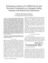
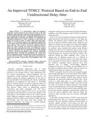
Substituting (31) into (29), we obtain the results shown in<br />
Figure 1. To compare the difference between orthogonal<br />
signaling <strong>and</strong> quasi-orthogonal CCSK, the probability <strong>of</strong><br />
symbol error for 32-ary orthogonal signaling is also shown in<br />
the figure. As expected, the performance <strong>of</strong> 32-chip CCSK is<br />
inferior to that <strong>of</strong> 32-ary orthogonal signaling by about 2 dB at<br />
PS<br />
−5<br />
= 10 ; however, the advantage <strong>of</strong> using CCSK is that only<br />
one detector branch is required to recover the original symbol<br />
instead <strong>of</strong> thirty-two detector branches.<br />
P s<br />
10 0<br />
10 -1<br />
10 -2<br />
10 -3<br />
10 -4<br />
10 -5<br />
10 -6<br />
10 -7<br />
10 -8<br />
32-ary orthogonal signaling<br />
32-chip CCSK, upper bound<br />
10<br />
0 2 4 6 8 10 12 14<br />
-9<br />
E /N (dB)<br />
b o<br />
Fig. 1. Probability <strong>of</strong> symbol error in AWGN: the 32-chip CCSK sequence<br />
chosen for JTIDS versus 32-ary orthogonal signaling.<br />
IV. SIMULATION<br />
To check the analytic upper bound derived in the last<br />
section, a Monte Carlo simulation with stratified sampling [9]<br />
is written to obtain the conditional probabilities <strong>of</strong> symbol<br />
error for 7 ≤ N ≤ 32 . This simulation is implemented in a<br />
manner similar to that <strong>of</strong> finding the analytical upper bound;<br />
that is, the simulation is done case-by-case for different N .<br />
Starting from N = 7 <strong>and</strong> given that symbol 0 is sent, the<br />
major steps <strong>of</strong> the simulation are as follows. First, in each<br />
iteration, (i) generate r<strong>and</strong>omly a 32-chip sequence with seven<br />
chip errors relative to the original 32-chip sequence for<br />
symbol 0 to model noisy 32-chip sequence, (ii) cross-correlate<br />
the noisy 32-chip sequence with all <strong>of</strong> the 32 local sequences<br />
to yield 32 cross-correlation values ℜ0, ℜ1,..., ℜ 31 , (iii) calculate<br />
the probability <strong>of</strong> symbol error based on the following rules: if<br />
ℜ >ℜ for 1 ≤i≤ 31 , the conditional probability <strong>of</strong> symbol<br />
i<br />
0<br />
error is one; if i 0<br />
ℜ =ℜ for 1 ≤i≤ 31 , the conditional<br />
probability <strong>of</strong> symbol error is τ ( τ + 1)<br />
, where τ is the total<br />
number <strong>of</strong> ties; if ℜ i
TABLE VI CONDITIONAL PROBABILITIES OF SYMBOL ERROR: THE CCSK<br />
SEQUENCE CHOSEN BY JTIDS VERSUS THE NEW CCSK SEQUENCE.<br />
N = j<br />
ζ<br />
ζ UBj<br />
SIM j<br />
ζ<br />
'<br />
UBj<br />
ζ<br />
'<br />
SIM j<br />
0 0 0 0 0<br />
1 0 0 0 0<br />
<br />
5 0 0 0 0<br />
6 0 0 0 0<br />
7 0.0015 0.0015 0 0<br />
8 0.0207 0.0194 0.0147 0.0143<br />
9 0.1166 0.1126 0.1040 0.1025<br />
10 0.4187 0.3669 0.4023 0.3550<br />
11 1.0 0.7093 1.0 0.7140<br />
12 1.0 0.9351 1.0 0.9367<br />
13 1.0 0.9953 1.0 0.9956<br />
14 1.0 1.0 1.0 0.9999<br />
15 1.0 1.0 1.0 1.0<br />
<br />
32 1.0 1.0 1.0 1.0<br />
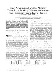
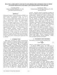
'<br />
Replacing ζ SIM with ζ j<br />
SIM in (32), we obtain the<br />
j<br />
probability <strong>of</strong> symbol error for the new CCSK sequence in<br />
AWGN. To compare the difference between the CCSK<br />
sequence chosen for JTIDS <strong>and</strong> the new CCSK sequence, both<br />
simulation results are shown in Figure 3. As can be seen, the<br />
results obtained with the new sequence are only slightly better<br />
than those obtained with the original JTIDS sequence since<br />
performance is determined at the symbol level rather than the<br />
chip level. In essence, for practical values <strong>of</strong> P c , the first nonzero<br />
term in (32) is not dominant.<br />
P s<br />
10 0<br />
10 -1<br />
10 -2<br />
10 -3<br />
10 -4<br />
10 -5<br />
10 -6<br />
10 -7<br />
10 -8<br />
JTIDS sequence<br />
New sequence<br />
10<br />
0 2 4 6 8 10 12 14<br />
-9<br />
E /N (dB)<br />
b o<br />
Fig. 3. Probability <strong>of</strong> symbol error in AWGN (simulation): the new CCSK<br />
sequence versus the CCSK sequence chosen for JTIDS.<br />
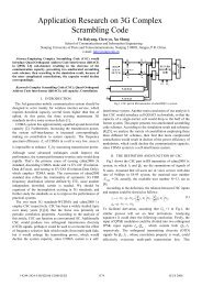
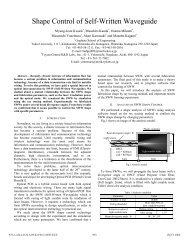
Replacing ζ UB with<br />
j<br />
'<br />
ζ UB in (29), we obtain the upper<br />
j<br />
bound <strong>of</strong> the probability <strong>of</strong> symbol error for the new CCSK<br />
sequence in AWGN. To compare the difference between the<br />
analytic upper bound <strong>and</strong> the simulation, both results are<br />
shown in Figure 4. As before, the analytic results given by<br />
(29) yield a tight upper bound.<br />
P s<br />
10 0<br />
10 -1<br />
10 -2<br />
10 -3<br />
10 -4<br />
10 -5<br />
10 -6<br />
10 -7<br />
10 -8<br />
<strong>Simulation</strong><br />
Upper bound<br />
10<br />
0 2 4 6 8 10 12 14<br />
-9<br />
E /N (dB)<br />
b o<br />
Fig. 4. Probability <strong>of</strong> symbol error for the new CCSK sequence in AWGN:<br />
analytical upper bound versus Monte Carlo simulation.<br />
VI. CONCLUSION<br />
In this paper, an analytic upper bound on the probability <strong>of</strong><br />
symbol error <strong>of</strong> CCSK is derived for the CCSK sequence<br />
chosen for JTIDS. The probability <strong>of</strong> symbol error obtained<br />
with the analytic upper bound was compared to the probability<br />
<strong>of</strong> symbol error obtained by Monte Carlo simulation for<br />
AWGN. The results show that the analytic method yields a<br />
tight upper bound. In addition to the CCSK sequence chosen<br />
for JTIDS, a new CCSK sequence with a smaller maximum<br />
<strong>of</strong>f-peak cross-correlation value is introduced <strong>and</strong> evaluated<br />
both analytically <strong>and</strong> by Monte Carlo simulation. The results<br />
obtained for this new sequence compare favorably to the<br />
sequence chosen for JTIDS.<br />
REFERENCES<br />
[1] M. B. Pursely, T. C. Royster, IV, <strong>and</strong> M. Y. Tan, “High-rate directsequence<br />
spread spectrum,” Proc. IEEE Military Commun. Conf., vol. 2,<br />
pp. 1101-1106, 2003.<br />
[2] H. Wang, J. Kuang, Z. Wang, <strong>and</strong> H. Xu, “Transmission performance<br />
evaluation <strong>of</strong> JTIDS,” Proc. IEEE Military Commun. Conf., vol. 4, pp.<br />
2264-2268, 2005.<br />
[3] F. J. Block, “Comparison <strong>of</strong> jamming robustness <strong>of</strong> airborne networking<br />
waveforms,” Proc. IEEE Military Commun. Conf., vol. 4, pp. 2119-<br />
2125, 2005.<br />
[4] M. B. Pursley, <strong>and</strong> T. C. Royster, “High-rate direct-sequence spread<br />
spectrum with error-control coding,” IEEE Trans. Commun., vol. 54, no.<br />
9, pp. 1693-1702, Sept. 2006.<br />
[5] L. Sadiq <strong>and</strong> A. H. Aghvami, “<strong>Performance</strong> <strong>of</strong> a coded hybrid spread<br />
spectrum communication system in the presence <strong>of</strong> partial b<strong>and</strong> noise<br />
<strong>and</strong> multiple access interference,” Proc. IEEE Military Commun. Conf.,<br />
vol. 3, pp. 817-821, 1988.<br />
[6] S. M. Ross, “Introduction to Probability Models”, 8th ed., San Diego,<br />
Academic Press, pp. 99, 2003.<br />
[7] S. M. Ross, “Introduction to Probability Models”, 8th ed., San Diego,<br />
Academic Press, pp. 119, 2003.<br />
[8] S. Pasupathy, “Minimum shift keying: a spectrally efficient<br />
modulation,” IEEE Commun. Mag., vol. 17, Issue 4, pp. 14-22, Jul.<br />
1979.<br />
[9] S. M. Ross, “<strong>Simulation</strong>,” 3rd ed., San Diego: Academic Press, pp. 158-<br />
167, 2002.