Performance Analysis of a JTIDS/Link-16-type Waveform ...
Performance Analysis of a JTIDS/Link-16-type Waveform ...
Performance Analysis of a JTIDS/Link-16-type Waveform ...

You also want an ePaper? Increase the reach of your titles
YUMPU automatically turns print PDFs into web optimized ePapers that Google loves.
second layer <strong>of</strong> transmission security, each 32-chip CCSK<br />
sequence is scrambled with a 32-chip pseudo-noise sequence.<br />
The resulting 32-chip sequence is modulated for transmission<br />
with MSK to generate analog pulses. Each pulse is then upconverted<br />
to one <strong>of</strong> the 51 possible carrier frequencies, which<br />
contributes a third layer <strong>of</strong> transmission security. Normally,<br />
the starting point <strong>of</strong> the pulse train is pseudo-randomly<br />
jittered, which provides a fourth layer <strong>of</strong> transmission security<br />
since it can make it difficult for a jammer to decide when to<br />
turn on the jamming signal. After up-conversion, the signal is<br />
amplified, filtered, and transmitted over the channel [6].<br />
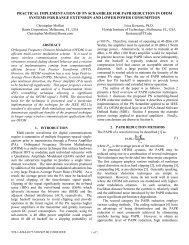
B. <strong>JTIDS</strong>-<strong>type</strong> Receiver<br />
At the receiver (Figure 2), the receiving process is the<br />
reverse <strong>of</strong> the transmission process. After frequency dehopping,<br />
MSK chip demodulation, and de-scrambling by the<br />
32-chip PN sequence, each 5-bit channel symbol is recovered<br />
by a CCSK symbol demodulator. The determination <strong>of</strong> which<br />
5-bit channel symbol was received is done by computing the<br />
cross-correlation between the de-scrambled 32-chip sequence<br />
and all possible 32 sequences, and the decision is made by<br />
choosing the 5-bit channel symbol corresponding to the<br />
branch with the largest cross-correlation value. After symbol<br />
de-interleaving, the channel data symbols are decoded by a<br />
(31,15) RS decoder. If the decoding is successful, the data<br />
symbols are converted into a bit stream which are sent to the<br />
upper layer.<br />
<strong>Link</strong>-<strong>16</strong><br />
message<br />
(31,15)<br />
RS Decoder<br />
Symbol<br />
De-interleaver<br />
CCSK<br />
32-ary Symbol<br />
Demodulator<br />
Fig. 2. Model <strong>of</strong> a <strong>JTIDS</strong>-<strong>type</strong> receiver.<br />
32-Chip<br />
PN Sequence<br />
De-scrambling<br />
MSK<br />
Chip<br />
Demodulator<br />
Frequency<br />
De-hopping<br />
III. PERFORMANCE ANALYSIS<br />
Given the assumptions that frequency de-hopping is<br />
perfectly synchronized with the frequency-hopped waveform<br />
and that the signal-to-noise ratio (SNR) is large, the MSK chip<br />
demodulator recovers the original scrambled 32-chip<br />
sequence. Given that de-scrambling is perfectly synchronized,<br />
the CCSK symbol demodulator detects the original 5-bit<br />
coded symbol. As seen in Figure 2, to evaluate the probability<br />
<strong>of</strong> symbol error <strong>of</strong> a <strong>JTIDS</strong>/<strong>Link</strong>-<strong>16</strong>-<strong>type</strong> waveform, the<br />
probability <strong>of</strong> channel chip error at the output <strong>of</strong> the MSK chip<br />
demodulator and the probability <strong>of</strong> channel symbol error at the<br />
output <strong>of</strong> the CCSK symbol demodulator are both required.<br />
A. Probability <strong>of</strong> Channel Chip Error<br />
MSK can be considered as a special case <strong>of</strong> <strong>of</strong>fset<br />
quadrature phase-shift keying (OQPSK) with sinusoidal pulse<br />
shaping [7]. When a coherent matched filter or correlator is<br />
used to recover the data chips, MSK has the same performance<br />
as binary PSK and OQPSK; that is,<br />
⎛<br />
Pc= Q ⎜<br />
⎝<br />
2E<br />
⎞ c<br />
⎟,<br />
N ⎟<br />
0 ⎠<br />
(1)<br />
where E c is the average energy per chip. Since each 5-bit<br />
symbol is converted into 32 chips, E = 5E = 32E<br />
; where<br />
s b c<br />
E S is the average energy per symbol and E b is the average<br />
energy per bit. Therefore, (1) can be expressed as<br />
⎛ 10E<br />
⎞ b<br />
Pc= Q⎜<br />
⎟.<br />
(2)<br />
⎜ 32N<br />
⎟<br />
⎝ 0 ⎠<br />
The <strong>JTIDS</strong> waveform is currently received noncoherently at<br />
the chip level, but the performance with coherent detection is<br />
evaluated in order to determine performance if coherent chip<br />
demodulation were practical. The analysis presented in this<br />
paper can easily be modified to evaluate noncoherent chip<br />
demodulation. From (2), when forward error correction (FEC)<br />
coding is used, the probability <strong>of</strong> channel chip error for a<br />
<strong>JTIDS</strong>/<strong>Link</strong>-<strong>16</strong>-<strong>type</strong> waveform in AWGN is given by<br />
⎛ 10E ⎞<br />
b ⎛ 10rE<br />
⎞<br />
c<br />
b<br />
pc= Q⎜ ⎟=<br />
Q⎜<br />
⎟,<br />
(3)<br />
⎜ 32N ⎟ ⎜<br />
0 32N<br />
⎟<br />
⎝ ⎠ ⎝ 0 ⎠<br />
where Eb = rE<br />
c b is the average energy per coded bit, and r is<br />
the code rate.<br />
The <strong>Link</strong>-<strong>16</strong> message data can be sent with either a singlepulse<br />
structure or a double-pulse structure [8]. The doublepulse<br />
structure increases the anti-jam capability <strong>of</strong> the link<br />
since it provides a diversity <strong>of</strong> L = 2 . Note that (3) is only<br />
valid for the single-pulse structure. To recover the data sent<br />
with the double-pulse structure, s<strong>of</strong>t decision (SD) combining<br />
on a chip-by-chip basis is assumed in the coherent MSK chip<br />
demodulator as shown in Figure 3.<br />
rt ()<br />
πt<br />
cos cos 2π<br />
ft c<br />
2T<br />
c<br />
c<br />
( 2k 1)<br />
Tc<br />
( 2k 1)<br />
T dt<br />
+<br />
−<br />
∫<br />
( 2k+ 2)<br />
Tc<br />
∫ dt<br />
2kTc<br />
πt<br />
sin sin 2π<br />
fct 2T<br />
t = ( 2k+ 2) Tc<br />
c<br />
t = ( 2k+ 1) Tc<br />
1 st pulse<br />
even chips<br />
2 nd pulse<br />
even chips<br />
1 st pulse<br />
odd chips<br />
2 nd pulse<br />
odd chips<br />
SD combining<br />
+<br />
Σ<br />
+<br />
+<br />
Σ<br />
+<br />
SD combining<br />
Fig. 3. MSK coherent chip demodulator with double-pulse/SD combining.<br />
When the double-pulse structure is used, <strong>JTIDS</strong> is a hybrid<br />
DS/FFH spread spectrum system with sequential diversity<br />
L = 2 since each symbol is transmitted twice on two different<br />
carrier frequencies. Thus, the average energy per symbol is<br />
Es = LEp<br />
(4)<br />
where L = 2 , and E p is the average energy per pulse. Since<br />
Es = 5Eb<br />
and E p = 5Eb',<br />
from (4) we get<br />
Eb = LEb'<br />
(5)<br />
where E b ' is the average energy per bit per pulse. Using (5) in<br />
(3), we obtain an expression for the probability <strong>of</strong> channel<br />
chip error <strong>of</strong> a <strong>JTIDS</strong>/<strong>Link</strong>-<strong>16</strong>-<strong>type</strong> waveform in AWGN as<br />
+<br />
-<br />
+<br />
-<br />
S/P<br />
ˆS