Performance Analysis of a JTIDS/Link-16-type Waveform ...
Performance Analysis of a JTIDS/Link-16-type Waveform ...
Performance Analysis of a JTIDS/Link-16-type Waveform ...

Create successful ePaper yourself
Turn your PDF publications into a flip-book with our unique Google optimized e-Paper software.
<strong>Performance</strong> <strong>Analysis</strong> <strong>of</strong> a <strong>JTIDS</strong>/<strong>Link</strong>-<strong>16</strong>-<strong>type</strong><br />
<strong>Waveform</strong> Transmitted over Nakagami Fading<br />
Channels with Pulsed-Noise Interference<br />
Abstract—The Joint Tactical Information Distribution System<br />
(<strong>JTIDS</strong>) is the communication terminal <strong>of</strong> <strong>Link</strong>-<strong>16</strong>. <strong>JTIDS</strong> is a<br />
hybrid direct sequence/frequency-hopping spread spectrum<br />
system and features Reed-Solomon codes for channel coding,<br />
cyclic code-shift keying for 32-ary symbol modulation, minimumshift<br />
keying for chip modulation, symbol interleaving, chip<br />
sequence scrambling and random jittering for transmission<br />
security, and a double-pulse structure for diversity. Assuming<br />
that coherent chip demodulation is practical, we investigate the<br />
probability <strong>of</strong> symbol error <strong>of</strong> a <strong>JTIDS</strong>/<strong>Link</strong>-<strong>16</strong>-<strong>type</strong> waveform<br />
for both the single- and the double-pulse structure transmitted<br />
over a slow, flat Nakagami fading channel in the presence <strong>of</strong><br />
pulsed-noise interference (PNI) in this paper. In general, the<br />
results show that the double-pulse structure always outperforms<br />
the single-pulse structure, whether the PNI is present or not and<br />
whether the channel is fading or not. Furthermore, barrage noise<br />
interference has the most effect in degrading performance when<br />
signal-to-interference ratio (SIR) is small. When SIR is large,<br />
PNI with a smaller fraction <strong>of</strong> time that interference is on causes<br />
the greatest degradation.<br />
Index Terms—Joint Tactical Information Distribution System<br />
(<strong>JTIDS</strong>), <strong>Link</strong>-<strong>16</strong>, Nakagami fading, pulsed-noise interference,<br />
probability <strong>of</strong> symbol error.<br />
I. INTRODUCTION<br />
he Joint Tactical Information Distribution System (<strong>JTIDS</strong>)<br />
Tis<br />
the communication component <strong>of</strong> <strong>Link</strong>-<strong>16</strong>. <strong>JTIDS</strong> is a<br />
hybrid direct sequence/frequency-hopping (DS/FH) spread<br />
spectrum system and features Reed-Solomon (RS) codes for<br />
channel coding, cyclic code-shift keying (CCSK) for 32-ary<br />
baseband symbol modulation, minimum-shift keying (MSK)<br />
for chip modulation, symbol interleaving, chip sequence<br />
scrambling and random jittering for transmission security, and<br />
a double-pulse structure for diversity. In this paper, a<br />
<strong>JTIDS</strong>/<strong>Link</strong>-<strong>16</strong>-<strong>type</strong> system is first introduced, and then the<br />
probability <strong>of</strong> symbol error <strong>of</strong> a <strong>JTIDS</strong>/<strong>Link</strong>-<strong>16</strong>-<strong>type</strong><br />
waveform for both the single- and the double-pulse structure<br />
transmitted over a fading channel in the presence <strong>of</strong> pulsednoise<br />
interference (PNI) is investigated. Given the<br />
assumptions that the chip duration is less than the channel<br />
coherence time and that at a particular hop the signal<br />
bandwidth is less than the channel coherence bandwidth, the<br />
fading channel is modeled as a slow, flat Nakagami fading<br />
978-1-4244-2677-5/08/$25.00 ©2008 IEEE<br />
Chi-Han Kao, Frank Kragh, and Clark Robertson<br />
Electrical and Computer Engineering Department<br />
Naval Postgraduate School, Monterey, CA 93943-5121<br />
channel. The performance <strong>of</strong> hybrid DS/FH spread spectrum<br />
systems for various modulation schemes in the presence <strong>of</strong><br />
different <strong>type</strong>s <strong>of</strong> interference and fading has been<br />
investigated in [1]-[5], but only [1] attempts to evaluate the<br />
performance <strong>of</strong> the <strong>JTIDS</strong> waveform analytically in AWGN.<br />
Unfortunately, the results presented in [1] are based on the<br />
overly optimistic assumption that the cross-correlation values<br />
for the CCSK symbol demodulator are independent. Actually,<br />
it can be shown that these cross-correlation values are not<br />
independent.<br />
Currently, the <strong>JTIDS</strong> waveform is received noncoherently<br />
at the chip level, but in this paper the performance <strong>of</strong> a <strong>JTIDS</strong><strong>type</strong><br />
waveform with coherent detection is evaluated in order to<br />
ascertain the performance possible if coherent chip<br />
demodulation were practical. The analysis presented in this<br />
paper can easily be modified to evaluate performance with<br />
noncoherent chip demodulation.<br />
II. SYSTEM MODEL DESCRIPTION<br />
A. <strong>JTIDS</strong>-<strong>type</strong> Transmitter<br />
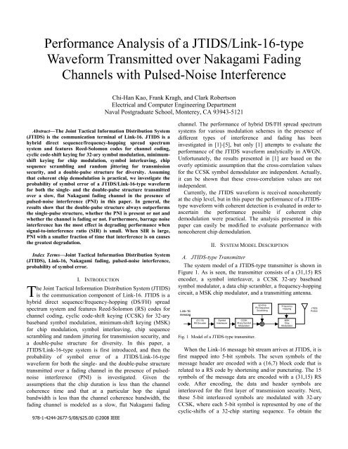
The system model <strong>of</strong> a <strong>JTIDS</strong>-<strong>type</strong> transmitter is shown in<br />
Figure 1. As is seen, the transmitter consists <strong>of</strong> a (31,15) RS<br />
encoder, a symbol interleaver, a CCSK 32-ary baseband<br />
symbol modulator, a data chip scrambler, a frequency-hopping<br />
circuit, a MSK chip modulator, and a transmitting antenna.<br />
<strong>Link</strong>-<strong>16</strong><br />
messag<br />
(31,15)<br />
RS Encoder<br />
Symbol<br />
Interleaver<br />
CCSK<br />
M-ary Symbol<br />
Modulation<br />
Fig. 1 Model <strong>of</strong> a <strong>JTIDS</strong>-<strong>type</strong> transmitter.<br />
32-Chip<br />
PN Sequence<br />
Scrambing<br />
Frequency<br />
Hopping<br />
MSK<br />
Chip<br />
Modulation<br />
<strong>JTIDS</strong><br />
Pulses<br />
When the <strong>Link</strong>-<strong>16</strong> message bit stream arrives at <strong>JTIDS</strong>, it is<br />
first mapped into 5-bit symbols. The seven symbols <strong>of</strong> the<br />
message header are encoded with a (<strong>16</strong>,7) block code that is<br />
related to a RS code by shortening and/or puncturing. The 15<br />
symbols <strong>of</strong> the message data are encoded with a (31,15) RS<br />
code. After encoding, the data and header symbols are<br />
interleaved for the first layer <strong>of</strong> transmission security. Next,<br />
these 5-bit interleaved symbols are modulated with 32-ary<br />
CCSK, where each 5-bit symbol is represented by one <strong>of</strong> the<br />
cyclic-shifts <strong>of</strong> a 32-chip starting sequence. To obtain the
second layer <strong>of</strong> transmission security, each 32-chip CCSK<br />
sequence is scrambled with a 32-chip pseudo-noise sequence.<br />
The resulting 32-chip sequence is modulated for transmission<br />
with MSK to generate analog pulses. Each pulse is then upconverted<br />
to one <strong>of</strong> the 51 possible carrier frequencies, which<br />
contributes a third layer <strong>of</strong> transmission security. Normally,<br />
the starting point <strong>of</strong> the pulse train is pseudo-randomly<br />
jittered, which provides a fourth layer <strong>of</strong> transmission security<br />
since it can make it difficult for a jammer to decide when to<br />
turn on the jamming signal. After up-conversion, the signal is<br />
amplified, filtered, and transmitted over the channel [6].<br />
B. <strong>JTIDS</strong>-<strong>type</strong> Receiver<br />
At the receiver (Figure 2), the receiving process is the<br />
reverse <strong>of</strong> the transmission process. After frequency dehopping,<br />
MSK chip demodulation, and de-scrambling by the<br />
32-chip PN sequence, each 5-bit channel symbol is recovered<br />
by a CCSK symbol demodulator. The determination <strong>of</strong> which<br />
5-bit channel symbol was received is done by computing the<br />
cross-correlation between the de-scrambled 32-chip sequence<br />
and all possible 32 sequences, and the decision is made by<br />
choosing the 5-bit channel symbol corresponding to the<br />
branch with the largest cross-correlation value. After symbol<br />
de-interleaving, the channel data symbols are decoded by a<br />
(31,15) RS decoder. If the decoding is successful, the data<br />
symbols are converted into a bit stream which are sent to the<br />
upper layer.<br />
<strong>Link</strong>-<strong>16</strong><br />
message<br />
(31,15)<br />
RS Decoder<br />
Symbol<br />
De-interleaver<br />
CCSK<br />
32-ary Symbol<br />
Demodulator<br />
Fig. 2. Model <strong>of</strong> a <strong>JTIDS</strong>-<strong>type</strong> receiver.<br />
32-Chip<br />
PN Sequence<br />
De-scrambling<br />
MSK<br />
Chip<br />
Demodulator<br />
Frequency<br />
De-hopping<br />
III. PERFORMANCE ANALYSIS<br />
Given the assumptions that frequency de-hopping is<br />
perfectly synchronized with the frequency-hopped waveform<br />
and that the signal-to-noise ratio (SNR) is large, the MSK chip<br />
demodulator recovers the original scrambled 32-chip<br />
sequence. Given that de-scrambling is perfectly synchronized,<br />
the CCSK symbol demodulator detects the original 5-bit<br />
coded symbol. As seen in Figure 2, to evaluate the probability<br />
<strong>of</strong> symbol error <strong>of</strong> a <strong>JTIDS</strong>/<strong>Link</strong>-<strong>16</strong>-<strong>type</strong> waveform, the<br />
probability <strong>of</strong> channel chip error at the output <strong>of</strong> the MSK chip<br />
demodulator and the probability <strong>of</strong> channel symbol error at the<br />
output <strong>of</strong> the CCSK symbol demodulator are both required.<br />
A. Probability <strong>of</strong> Channel Chip Error<br />
MSK can be considered as a special case <strong>of</strong> <strong>of</strong>fset<br />
quadrature phase-shift keying (OQPSK) with sinusoidal pulse<br />
shaping [7]. When a coherent matched filter or correlator is<br />
used to recover the data chips, MSK has the same performance<br />
as binary PSK and OQPSK; that is,<br />
⎛<br />
Pc= Q ⎜<br />
⎝<br />
2E<br />
⎞ c<br />
⎟,<br />
N ⎟<br />
0 ⎠<br />
(1)<br />
where E c is the average energy per chip. Since each 5-bit<br />
symbol is converted into 32 chips, E = 5E = 32E<br />
; where<br />
s b c<br />
E S is the average energy per symbol and E b is the average<br />
energy per bit. Therefore, (1) can be expressed as<br />
⎛ 10E<br />
⎞ b<br />
Pc= Q⎜<br />
⎟.<br />
(2)<br />
⎜ 32N<br />
⎟<br />
⎝ 0 ⎠<br />
The <strong>JTIDS</strong> waveform is currently received noncoherently at<br />
the chip level, but the performance with coherent detection is<br />
evaluated in order to determine performance if coherent chip<br />
demodulation were practical. The analysis presented in this<br />
paper can easily be modified to evaluate noncoherent chip<br />
demodulation. From (2), when forward error correction (FEC)<br />
coding is used, the probability <strong>of</strong> channel chip error for a<br />
<strong>JTIDS</strong>/<strong>Link</strong>-<strong>16</strong>-<strong>type</strong> waveform in AWGN is given by<br />
⎛ 10E ⎞<br />
b ⎛ 10rE<br />
⎞<br />
c<br />
b<br />
pc= Q⎜ ⎟=<br />
Q⎜<br />
⎟,<br />
(3)<br />
⎜ 32N ⎟ ⎜<br />
0 32N<br />
⎟<br />
⎝ ⎠ ⎝ 0 ⎠<br />
where Eb = rE<br />
c b is the average energy per coded bit, and r is<br />
the code rate.<br />
The <strong>Link</strong>-<strong>16</strong> message data can be sent with either a singlepulse<br />
structure or a double-pulse structure [8]. The doublepulse<br />
structure increases the anti-jam capability <strong>of</strong> the link<br />
since it provides a diversity <strong>of</strong> L = 2 . Note that (3) is only<br />
valid for the single-pulse structure. To recover the data sent<br />
with the double-pulse structure, s<strong>of</strong>t decision (SD) combining<br />
on a chip-by-chip basis is assumed in the coherent MSK chip<br />
demodulator as shown in Figure 3.<br />
rt ()<br />
πt<br />
cos cos 2π<br />
ft c<br />
2T<br />
c<br />
c<br />
( 2k 1)<br />
Tc<br />
( 2k 1)<br />
T dt<br />
+<br />
−<br />
∫<br />
( 2k+ 2)<br />
Tc<br />
∫ dt<br />
2kTc<br />
πt<br />
sin sin 2π<br />
fct 2T<br />
t = ( 2k+ 2) Tc<br />
c<br />
t = ( 2k+ 1) Tc<br />
1 st pulse<br />
even chips<br />
2 nd pulse<br />
even chips<br />
1 st pulse<br />
odd chips<br />
2 nd pulse<br />
odd chips<br />
SD combining<br />
+<br />
Σ<br />
+<br />
+<br />
Σ<br />
+<br />
SD combining<br />
Fig. 3. MSK coherent chip demodulator with double-pulse/SD combining.<br />
When the double-pulse structure is used, <strong>JTIDS</strong> is a hybrid<br />
DS/FFH spread spectrum system with sequential diversity<br />
L = 2 since each symbol is transmitted twice on two different<br />
carrier frequencies. Thus, the average energy per symbol is<br />
Es = LEp<br />
(4)<br />
where L = 2 , and E p is the average energy per pulse. Since<br />
Es = 5Eb<br />
and E p = 5Eb',<br />
from (4) we get<br />
Eb = LEb'<br />
(5)<br />
where E b ' is the average energy per bit per pulse. Using (5) in<br />
(3), we obtain an expression for the probability <strong>of</strong> channel<br />
chip error <strong>of</strong> a <strong>JTIDS</strong>/<strong>Link</strong>-<strong>16</strong>-<strong>type</strong> waveform in AWGN as<br />
+<br />
-<br />
+<br />
-<br />
S/P<br />
ˆS
⎛ 10rLE<br />
⎞ b'<br />
pc= Q⎜<br />
⎟,<br />
(6)<br />
⎜ 32N<br />
⎟<br />
⎝ 0 ⎠<br />
where L = 1 for the single-pulse structure, and L = 2 for the<br />
double-pulse structure. Note that if p c is expressed in terms<br />
<strong>of</strong> b E instead <strong>of</strong> LE b'<br />
, then p c is the same for both the singleand<br />
the double-pulse structure in AWGN.<br />
B. Probability <strong>of</strong> Channel Symbol Error<br />
The probability <strong>of</strong> symbol error for the 32-ary CCSK<br />
sequence chosen for <strong>JTIDS</strong> is given by [9]<br />
32<br />
Ps= ∑ P{ symbol error N = j} P{ N = j}<br />
(7)<br />
j = 0<br />
where N is a binomial random variable which represents the<br />
total number <strong>of</strong> chip errors occur at the output <strong>of</strong> the MSK<br />
chip demodulator. Since the demodulation <strong>of</strong> CCSK is<br />
independent <strong>of</strong> the FEC coding, the probability <strong>of</strong> channel<br />
symbol error can be obtained from (7) as<br />
32 ⎛32⎞ j<br />
32−<br />
j<br />
ps = ∑ ζ j ⎜ ⎟ pc ( 1−<br />
pc)<br />
(8)<br />
j=<br />
0 ⎝ j ⎠<br />
where ζ j are the conditional probabilities <strong>of</strong> channel symbol<br />
error given that N = j chip errors occur at the output <strong>of</strong> the<br />
MSK chip demodulator, and p c is the probability <strong>of</strong> channel<br />
chip error. In [9], the values <strong>of</strong> ζ j were obtained both<br />
analytically and by Monte Carlo simulation. Since the analytic<br />
result ζ UB yields a tight upper bound, it is used to evaluate<br />
j<br />
<strong>JTIDS</strong>’s performance in this paper. Therefore, from (8),<br />
32 ⎛32⎞ j<br />
32−<br />
j<br />
ps < ∑ ζ UB p ( 1 ) .<br />
j ⎜ ⎟ c − pc<br />
(9)<br />
j = 0 ⎝ j ⎠<br />
C. <strong>Performance</strong> <strong>Analysis</strong> in AWGN<br />
As mentioned earlier, <strong>JTIDS</strong> uses a RS code for FEC<br />
coding. A RS code is a linear, nonbinary block code. For a tsymbol<br />
error correcting, nonbinary block code, the probability<br />
<strong>of</strong> decoder, or block, error is upper bounded by [10]<br />
n ⎛n⎞ i<br />
n−i PE ≤ ∑ ⎜ ⎟ ps( 1−<br />
ps)<br />
(10)<br />
i=+ t 1⎝i⎠<br />
where the equality holds for either a perfect code or a bounded<br />
distance decoder, and p s is the probability <strong>of</strong> channel symbol<br />
error. Since each block consists <strong>of</strong> n coded symbols, the<br />
probability <strong>of</strong> symbol error for a linear, nonbinary block code<br />
is obtained by approximating the probability <strong>of</strong> information<br />
symbol error given i channel symbol errors per block by in<br />
[11]. Substituting this into (10), we get<br />
n 1 ⎛n⎞ i<br />
n−i PS ≈ ∑ i⎜ ⎟ ps( 1 − ps)<br />
. (11)<br />
n i=+ t 1 ⎝i⎠ Now, using (6) with r = 15 31 and either L = 1 or 2 in (9)<br />
along with ζ UB from [9], we obtain<br />
j<br />
s p . Next, using p s in<br />
(11), we obtain the probability <strong>of</strong> symbol error <strong>of</strong> a<br />
<strong>JTIDS</strong>/<strong>Link</strong>-<strong>16</strong>-<strong>type</strong> waveform for either the single- or the<br />
double-pulse structure over AWGN.<br />
D. <strong>Performance</strong> <strong>Analysis</strong> in both AWGN and PNI<br />
When a <strong>JTIDS</strong>/<strong>Link</strong>-<strong>16</strong>-<strong>type</strong> waveform is subjected to both<br />
AWGN and PNI, (11) can still be used to evaluate the<br />
probability <strong>of</strong> symbol error since (11) is independent <strong>of</strong> the<br />
<strong>type</strong>s <strong>of</strong> noise and/or fading channels. Since the probability <strong>of</strong><br />
channel symbol error is determined at the symbol level instead<br />
<strong>of</strong> the chip level and since the PNI is assumed, the probability<br />
<strong>of</strong> channel symbol error shown in (8) must be modified as<br />
L ⎛L⎞ <br />
L−<br />
ps = ∑⎜ ⎟ ρ1 ( 1−ρ1)<br />
ps<br />
(12)<br />
<br />
=<br />
0 ⎝⎠ where L = 1 for a single-pulse, L = 2 for a double-pulse, and<br />
0< ρ1<br />
≤ 1 represents the fraction <strong>of</strong> time the PNI is turned on.<br />
Note that ρ 1 = 1 represents barrage noise interference (BNI).<br />
The probability <strong>of</strong> channel symbol error given that pulses<br />
are jammed s p is upper-bounded by<br />
<br />
32 ⎛32⎞ 32−<br />
j<br />
j<br />
ps < ∑ζ<br />
UB p ( 1 ) ,<br />
j ⎜ ⎟ c − pc<br />
(13)<br />
<br />
j=<br />
0 ⎝ j ⎠<br />
where = 0,..., L . The probability <strong>of</strong> channel chip error given<br />
that pulses are jammed c p is given by<br />
<br />
⎛ 0.3125rLE ⎞<br />
b '<br />
pc= Q⎜<br />
⎟.<br />
(14)<br />
⎜ N0 + ( NILρ1) ⎟<br />
⎝<br />
<br />
⎠<br />
Now, using (12) through (14) in (11) with r = 15 31,<br />
and<br />
either L = 1 or 2, we obtain the probability <strong>of</strong> symbol error <strong>of</strong><br />
a <strong>JTIDS</strong>/<strong>Link</strong>-<strong>16</strong>-<strong>type</strong> waveform for either the single- or the<br />
double-pulse structure in both AWGN and PNI.<br />
E. <strong>Performance</strong> <strong>Analysis</strong> over Nakagami Fading Channels<br />
The process <strong>of</strong> evaluating the performance <strong>of</strong> a<br />
<strong>JTIDS</strong>/<strong>Link</strong>-<strong>16</strong>-<strong>type</strong> waveform for the single-pulse structure<br />
in both AWGN and PNI over Nakagami fading channels is<br />
similar to that for channels with no fading. The only difference<br />
is that (14) with L = 1 is now a conditional probability <strong>of</strong><br />
channel chip error since the received signal amplitude a c<br />
fluctuates and is modeled as a Nakagami random variable with<br />
a probability density function (pdf)<br />
m<br />
2<br />
2 ⎛ m ⎞ ⎛<br />
2m−1 −ma<br />
⎞<br />
c<br />
ACc ⎜ ⎟<br />
( ) 2<br />
c ⎜ ⎟<br />
2<br />
c<br />
Γ m ⎜a ⎟ ⎜<br />
c a ⎟<br />
c<br />
f ( a ) = a exp , a ≥0<br />
(15)<br />
⎝ ⎠ ⎝ ⎠<br />
where Γ() i is the Gamma function, and m is the fading<br />
figure. When m < 1 , the fading is more severe than Rayleigh<br />
fading; m = 1 is Rayleigh fading; when m > 1 , there is a line<strong>of</strong>-sight<br />
(LOS) component to the received signal, and when<br />
2<br />
m →∞, there is no fading. Replacing E b ' with aT c b'<br />
in (14)<br />
with L = 1 and = 0 , we get<br />
⎛ 2<br />
0.3125racT<br />
⎞<br />
b'<br />
pc ( a )<br />
,<br />
0 c = Q⎜<br />
⎟<br />
(<strong>16</strong>)<br />
⎜ N ⎟<br />
⎝ 0 ⎠<br />
where T b ' is the bit duration per pulse. Similarly, with L = 1<br />
and = 1 , we get
⎛ 0.3125ra<br />
T ⎞<br />
pc ( a )<br />
.<br />
1 c = Q<br />
⎜ ⎟<br />
2<br />
c b'<br />
⎜ ⎟<br />
⎝<br />
N0 + NIρ1 ⎠<br />
2<br />
If γ = aT N , (<strong>16</strong>) can be rewritten as<br />
b c b'<br />
0<br />
( γ ) ( γ )<br />
c0b b<br />
(17)<br />
p = Q 0.3125 r ,<br />
(18)<br />
and the pdf in terms <strong>of</strong> γ b is given by<br />
m<br />
m−1<br />
γ ⎛ b m ⎞ ⎛−mγ ⎞ b<br />
fΓ<br />
( γ )<br />
exp , 0<br />
b b = ⎜ ⎟ ⎜ ⎟ γb<br />
≥ (19)<br />
Γ( m)<br />
⎜γ ⎟ ⎜<br />
b γ ⎟<br />
⎝ ⎠ ⎝ b ⎠<br />
2<br />
where γ b = aT c b'<br />
N0<br />
is defined as the ratio <strong>of</strong> the average<br />
energy per bit per pulse-to-noise power spectral density. If<br />
( )<br />
γT 2<br />
= aT c b' ⎡⎣N0 + NI<br />
ρ1<br />
⎤⎦<br />
, we can rewrite (17) as<br />
p γ = Q 0.3125 rγ<br />
,<br />
(20)<br />
( ) ( )<br />
c1T T<br />
and the pdf in terms <strong>of</strong> γ T is given by<br />
m<br />
m−1<br />
γ ⎛ T m ⎞ ⎛−mγ ⎞ T<br />
fΓ<br />
( γ )<br />
exp , 0<br />
T T = ⎜ ⎟ ⎜ ⎟ γT<br />
≥<br />
Γ( m)<br />
⎜γ ⎟ ⎜<br />
T γ ⎟<br />
⎝ ⎠ ⎝ T ⎠<br />
2<br />
where γ = aT N + ( N ρ )<br />
(21)<br />
T c b' ⎡⎣ 0 I 1 ⎤⎦<br />
. The average probability <strong>of</strong><br />
channel chip error when the PNI is <strong>of</strong>f is obtained from<br />
pc0 ∞<br />
= ∫ pc ( γ ) ( ) .<br />
0 b fΓγ b b dγ<br />
−∞<br />
b<br />
(22)<br />
Substituting (18) and (19) into (22), we obtain the average<br />
probability <strong>of</strong> channel chip error when the PNI is <strong>of</strong>f as<br />
m<br />
m−1<br />
∞ γ ⎛ b m ⎞ ⎛−mγ ⎞ b<br />
c = ( γ ) 0 0<br />
b ⎜ γb<br />
( m)<br />
⎜ ⎟<br />
γ ⎟ ⎜ ⎟<br />
b γ ⎟<br />
b<br />
p ∫ Q 0.3125r Γ ⎝ ⎠<br />
exp<br />
⎝<br />
d<br />
⎠<br />
. (23)<br />
When m is an integer, (23) can be evaluated to obtain [12]<br />
m m−1<br />
k<br />
⎛1− μ ⎞ ⎛m− 1+<br />
k⎞⎛1+<br />
μ ⎞<br />
pc<br />
=<br />
0 ⎜ ⎟ ∑ ⎜ ⎟<br />
2 k = 0 k<br />
⎜ ⎟<br />
⎝ ⎠ ⎝ ⎠⎝<br />
2 ⎠<br />
(24)<br />
μ = γ m + γ and γ0= 0.3125rγ 2 . Similarly,<br />
where 0 ( 0)<br />
the average probability <strong>of</strong> channel chip error when the PNI is<br />
on is given by<br />
m m−1<br />
k<br />
⎛1− ν ⎞ ⎛m− 1+<br />
k⎞⎛1+<br />
ν ⎞<br />
pc<br />
=<br />
1 ⎜ ⎟ ∑ ⎜ ⎟<br />
2 k = 0 k<br />
⎜ ⎟<br />
⎝ ⎠ ⎝ ⎠⎝<br />
2 ⎠<br />
(25)<br />
ν = γ m + γ and γ1= 0.3125rγ 2 . Using (24)<br />
where 1 ( 1)<br />
and (25) in (13) along with ζ UB from [9], we obtain<br />
j<br />
T<br />
b<br />
p s and<br />
0<br />
p s , respectively. Using p<br />
1<br />
s and p<br />
0<br />
s in (12), we obtain p<br />
1<br />
s .<br />
Using p s in (11), we obtain the probability <strong>of</strong> symbol error <strong>of</strong><br />
a <strong>JTIDS</strong>/<strong>Link</strong>-<strong>16</strong>-<strong>type</strong> waveform for the single-pulse structure<br />
in both AWGN and PNI when the signal is transmitted over a<br />
slow, flat Nakagami fading channel.<br />
For the double-pulse structure, it is difficult to investigate<br />
the performance for a <strong>JTIDS</strong>/<strong>Link</strong>-<strong>16</strong>-<strong>type</strong> waveform in both<br />
AWGN and PNI when the signal is transmitted over<br />
Nakagami fading channels since it is extremely complex to<br />
obtain an analytic expression for the average probability <strong>of</strong><br />
channel chip error given that one pulse is jammed. Instead, the<br />
performance for a <strong>JTIDS</strong>/<strong>Link</strong>-<strong>16</strong>-<strong>type</strong> waveform in both<br />
AWGN and BNI transmitted over a slow, flat Nakagami<br />
fading channel is evaluated. In this case, we assume maximalratio<br />
detection with linear combining. For maximal-ratio<br />
detection with linear combining when both AWGN and BNI<br />
are present, the conditional probability <strong>of</strong> channel chip error<br />
given that both pulses are affected by BNI is<br />
⎛ 2 2<br />
0.3125r(<br />
ac + ac ) T ⎞<br />
b'<br />
pc( ac) = Q⎜<br />
⎟.<br />
(26)<br />
⎜ N0+ N ⎟<br />
I<br />
⎝ ⎠<br />
We can rewrite (26) as<br />
p γ = Q 0.3125r<br />
γ + γ<br />
(27)<br />
( )<br />
c( T ) ( T T )<br />
since<br />
2<br />
aT ( N N ) γ γ γ<br />
γ T = c b' 0 + I . If T T T<br />
∗ ∗<br />
( γ ) ( γ )<br />
∗ = + , (27) becomes<br />
p = Q 0.3125 r ,<br />
(28)<br />
c T T<br />
and the pdf in terms <strong>of</strong> γ T<br />
∗ is given by<br />
f<br />
( )<br />
( )<br />
∗<br />
2m−1 2m<br />
γ ∗<br />
T ⎛ m ⎞ ⎛ ∗ −mγ<br />
⎞ T ∗<br />
T ⎜ ⎟ T<br />
γ ⎟ ⎜ ⎟<br />
T γ ⎟<br />
T<br />
γ = exp , γ ≥0<br />
Γ ⎝ ⎠ ⎝ ⎠<br />
∗<br />
ΓT<br />
( 2m)<br />
where<br />
2<br />
aT ( N N )<br />
(29)<br />
γ T = c b' 0 + I .<br />
The average probability <strong>of</strong> channel chip error given that<br />
both pulses are affected by BNI is<br />
∞<br />
∗ ∗ ∗<br />
pc = pc ( γT ) f ∗ ∫ ( γT ) dγT.<br />
−∞<br />
ΓT<br />
Substituting (28) and (29) into (30), we obtain<br />
(30)<br />
( )<br />
∗<br />
2m−1 2m<br />
γ ∗<br />
∞<br />
T ⎛m⎞ ⎛ ∗ −mγ<br />
⎞ T ∗<br />
c = ( γ ) 0<br />
T ⎜ γT<br />
( 2m)<br />
⎜ ⎟<br />
γ ⎟ ⎜ ⎟<br />
T γ ⎟<br />
T<br />
p ∫ Q 0.3125r Γ ⎝ ⎠<br />
exp<br />
⎝<br />
d<br />
⎠<br />
. (31)<br />
When m is an integer, (31) can be evaluated to obtain<br />
2m 2m−1 k<br />
⎛1− β ⎞ ⎛2m− 1+<br />
k⎞⎛1+<br />
β ⎞<br />
pc<br />
= ⎜ ⎟ ∑ ⎜ ⎟<br />
2 k = 0 k<br />
⎜ ⎟<br />
⎝ ⎠ ⎝ ⎠⎝<br />
2 ⎠<br />
(32)<br />
β γ 2m γ γ = rγ<br />
. Using (32) in<br />
= + and 2 0.3125 T<br />
where 2 ( 2)<br />
(9) along with ζ UB from [9], we obtain<br />
j<br />
s p . Next, using p s in<br />
(11), we obtain the probability <strong>of</strong> symbol error <strong>of</strong> a<br />
<strong>JTIDS</strong>/<strong>Link</strong>-<strong>16</strong>-<strong>type</strong> waveform for the double-pulse structure<br />
in both AWGN and BNI when the signal is transmitted over a<br />
slow, flat Nakagami fading channel.<br />
IV. NUMERICAL RESULTS<br />
The probabilities <strong>of</strong> symbol error <strong>of</strong> a <strong>JTIDS</strong>/<strong>Link</strong>-<strong>16</strong>-<strong>type</strong><br />
waveform for both the single- and the double-pulse structure<br />
in AWGN are shown in Figure 4. As expected, the doublepulse<br />
structure outperforms the single-pulse structure in terms<br />
<strong>of</strong> average energy per bit per pulse b '<br />
b ' 0<br />
while the b ' 0<br />
E . At<br />
P<br />
−5<br />
S = 10 , the<br />
E N required for the double-pulse structure is about 4 dB,<br />
E N required for the single-pulse structure is<br />
about 7.1 dB. In other words, the double-pulse structure<br />
−5<br />
outperforms the single-pulse structure by 3.1 dB at PS<br />
= 10<br />
in AWGN.
P s<br />
10 0<br />
10 -1<br />
10 -2<br />
10 -3<br />
10 -4<br />
10 -5<br />
10 -6<br />
10 -7<br />
10 -8<br />
Single-pulse<br />
Double-pulse<br />
10<br />
0 2 4 6 8 10 12 14 <strong>16</strong> 18 20<br />
-9<br />
E /N (dB)<br />
b′ o<br />
Fig. 4. Probability <strong>of</strong> symbol error (tight upper bound) for a <strong>JTIDS</strong>/<strong>Link</strong>-<strong>16</strong><strong>type</strong><br />
waveform in AWGN: single-pulse versus double-pulse structure.<br />
When PNI is present, the probabilities <strong>of</strong> symbol error for<br />
both the single- and the double-pulse structure are shown in<br />
E N = 15 and 10 dB, respectively.<br />
Figures 5 and 6 where b'<br />
0<br />
Several observations can be made. First, for both the singleand<br />
the double-pulse structure, the value <strong>of</strong> ρ 1 that maximizes<br />
the probability <strong>of</strong> symbol error decreases as Eb'N I increases.<br />
For example, for the double-pulse structure in Figure 5, ρ 1 = 1<br />
has the most effect in degrading performance when Eb'N I is<br />
less than 2 dB, while ρ 1 = 0.1 causes the greatest degradation<br />
when Eb'N I is greater than 7 dB. Similar results are seen in<br />
Figure 6. Second, the double-pulse structure outperforms the<br />
single-pulse structure, whether ρ 1 is large or small. For<br />
example, in Figure 5, for ρ 1 = 0.5 , the double-pulse structure<br />
−5<br />
outperforms the single-pulse structure by 4.2 dB at PS<br />
= 10 ,<br />
and for ρ 1 = 0.1,<br />
the double-pulse structure outperforms the<br />
−5<br />
single-pulse structure by 3.2 dB at PS<br />
= 10 . Lastly, the<br />
double-pulse structure outperforms the single-pulse structure<br />
by a greater margin as Eb ' N 0 decreases. For example, in<br />
Figure 6 where Eb ' N 0 is 10 dB, for ρ 1 = 0.5 , the doublepulse<br />
structure outperforms the single-pulse structure by 5.2<br />
−5<br />
dB (an increase <strong>of</strong> 1 dB) at PS<br />
= 10 , and for ρ 1 = 0.1,<br />
the<br />
double-pulse structure outperforms the single-pulse structure<br />
by 3.5 dB (an increase <strong>of</strong> 0.3 dB).<br />
Since <strong>JTIDS</strong> is operated in the UHF band (LOS is required),<br />
the range <strong>of</strong> the fading figure is 1 < m > 1,<br />
the<br />
performance for both the single- and the double-pulse<br />
structure when the signal is transmitted over a slow, flat<br />
Nakagami fading channel is virtually identical to that obtained<br />
when there is no channel fading as shown in Figures 5 and 6.<br />
When m = 2 , the probabilities <strong>of</strong> symbol error <strong>of</strong> a<br />
<strong>JTIDS</strong>/<strong>Link</strong>-<strong>16</strong>-<strong>type</strong> waveform for both the single-pulse<br />
structure (in both AWGN and PNI) and the double-pulse<br />
structure (in both AWGN and BNI) are shown in Figures 7<br />
E N = and 10 dB, respectively.<br />
and 8 where ' 0 15<br />
b<br />
P s<br />
10 0<br />
10 -1<br />
10 -2<br />
10 -3<br />
10 -4<br />
10 -5<br />
10 -6<br />
10 -7<br />
10 -8<br />
ρ 1 = 1, SP<br />
ρ 1 = 0.5, SP<br />
ρ 1 = 0.3, SP<br />
ρ 1 = 0.2, SP<br />
ρ 1 = 0.1, SP<br />
ρ 1 = 1, DP<br />
ρ 1 = 0.5, DP<br />
ρ 1 = 0.3, DP<br />
ρ 1 = 0.2, DP<br />
ρ 1 = 0.1, DP<br />
10<br />
0 2 4 6 8 10 12 14 <strong>16</strong> 18 20 22 24<br />
-9<br />
E /N (dB)<br />
b′ I<br />
Fig. 5. Probability <strong>of</strong> symbol error for a <strong>JTIDS</strong>/<strong>Link</strong>-<strong>16</strong>-<strong>type</strong> waveform in<br />
E N = dB: single- versus double-pulse structure.<br />
AWGN and PNI where ' 0 15<br />
b<br />
P s<br />
10 0<br />
10 -1<br />
10 -2<br />
10 -3<br />
10 -4<br />
10 -5<br />
10 -6<br />
10 -7<br />
10 -8<br />
ρ 1 = 1, SP<br />
ρ 1 = 0.5, SP<br />
ρ 1 = 0.3, SP<br />
ρ 1 = 0.2, SP<br />
ρ 1 = 0.1, SP<br />
ρ 1 = 1, DP<br />
ρ 1 = 0.5, DP<br />
ρ 1 = 0.3, DP<br />
ρ 1 = 0.2, DP<br />
ρ 1 = 0.1, DP<br />
10<br />
0 2 4 6 8 10 12 14 <strong>16</strong> 18 20 22 24<br />
-9<br />
E /N (dB)<br />
b′ I<br />
Fig. 6. Probability <strong>of</strong> symbol error for a <strong>JTIDS</strong>/<strong>Link</strong>-<strong>16</strong>-<strong>type</strong> waveform in<br />
E N = dB: single- versus double-pulse structure.<br />
AWGN and PNI where ' 0 10<br />
b<br />
P s<br />
10 0<br />
10 -1<br />
10 -2<br />
10 -3<br />
10 -4<br />
10 -5<br />
10 -6<br />
10 -7<br />
10 -8<br />
ρ 1 = 1, SP<br />
ρ 1 = 0.5, SP<br />
ρ 1 = 0.3, SP<br />
ρ 1 = 0.2, SP<br />
ρ 1 = 0.1, SP<br />
ρ 1 = 1, DP<br />
10<br />
0 2 4 6 8 10 12 14 <strong>16</strong> 18 20 22 24<br />
-9<br />
E /N (dB)<br />
b′ I<br />
Fig. 7. Probability <strong>of</strong> symbol error <strong>of</strong> a <strong>JTIDS</strong>/<strong>Link</strong>-<strong>16</strong>-<strong>type</strong> waveform for the<br />
single-pulse structure (in both AWGN and PNI) and the double-pulse<br />
structure (in both AWGN and BNI) transmitted over a slow, flat Nakagami<br />
fading channel where ' 0 15<br />
b<br />
E N = dB and m =<br />
2.
P s<br />
10 0<br />
10 -1<br />
10 -2<br />
10 -3<br />
10 -4<br />
10 -5<br />
10 -6<br />
10 -7<br />
10 -8<br />
ρ 1 = 1, SP<br />
ρ 1 = 0.5, SP<br />
ρ 1 = 0.3, SP<br />
ρ 1 = 0.2, SP<br />
ρ 1 = 0.1, SP<br />
ρ 1 = 1, DP<br />
10<br />
0 2 4 6 8 10 12 14 <strong>16</strong> 18 20 22 24<br />
-9<br />
E /N (dB)<br />
b′ I<br />
Fig. 8. Probability <strong>of</strong> symbol error <strong>of</strong> a <strong>JTIDS</strong>/<strong>Link</strong>-<strong>16</strong>-<strong>type</strong> waveform for the<br />
single-pulse structure (in both AWGN and PNI) and the double-pulse<br />
structure (in both AWGN and BNI) transmitted over a slow, flat Nakagami<br />
fading channel where ' 0 10<br />
b<br />
E N = dB and m = 2.<br />
From Figures 7 and 8, several observations can be made<br />
when compared to Figures 5 and 6, respectively. First, as<br />
expected, similar results but poorer performances are observed<br />
for smaller m. Second, for a fixed Eb ' N 0 , the double-pulse<br />
structure outperforms the single-pulse structure by a greater<br />
margin for smaller m . For example, in Figure 7 where m = 2 ,<br />
for ρ 1 = 1 , the double-pulse structure outperforms the single-<br />
−5<br />
pulse structure by 4.1 dB at PS<br />
= 10 , while in Figure 5<br />
where m →∞, for ρ 1 = 1 , the double-pulse structure<br />
−5<br />
outperforms the single-pulse structure by 3.4 dB at PS<br />
= 10 .<br />
Lastly, the double-pulse structure outperforms the single-pulse<br />
E N decreases. For<br />
structure by a greater margin as b ' 0<br />
example, in Figure 7 where b'<br />
0<br />
E N = 15 dB, the double-pulse<br />
structure outperforms the single-pulse structure by 4.1 dB for<br />
ρ 1 = 1 at PS<br />
−5<br />
= 10 , while in Figure 8 where Eb ' N 0 is<br />
reduced to 10 dB, the double-pulse structure outperforms the<br />
single-pulse structure by 6.5 dB for ρ 1 = 1 at PS<br />
−5<br />
= 10 .<br />
V. CONCLUSION<br />
In this paper, the probability <strong>of</strong> symbol error <strong>of</strong> a<br />
<strong>JTIDS</strong>/<strong>Link</strong>-<strong>16</strong>-<strong>type</strong> waveform for the single-pulse structure<br />
(in both AWGN and PNI) and the double-pulse structure (in<br />
both AWGN and BNI) transmitted over a slow, flat Nakagami<br />
fading channel is investigated. Several conclusions can be<br />
drawn as follows. First, the double-pulse structure always<br />
outperforms the single-pulse structure whether the PNI is<br />
present or not and whether the channel is fading or not.<br />
Second, for the single-pulse structure, the value <strong>of</strong> ρ 1 that<br />
maximizes the probability <strong>of</strong> symbol error decreases as<br />
E N increases; that is, BNI has the most effect in<br />
b'I degrading performance when b'I E N is small. When Eb'N I<br />
is large, PNI with a smaller fraction <strong>of</strong> time that interference is<br />
on causes the greatest degradation, whether the channel is<br />
fading or not. Third, when PNI is present in channels with no<br />
fading, the double-pulse structure always outperforms the<br />
single-pulse structure, whether b ' 0<br />
E N is large or small.<br />
Fourth, when the <strong>JTIDS</strong> signal is transmitted over a slow, flat<br />
Nakagami fading channel, the double-pulse structure<br />
outperforms the single-pulse structure by a greater margin for<br />
a smaller value <strong>of</strong> m when b ' 0<br />
E N is fixed. Lastly, for a<br />
fixed value <strong>of</strong> ρ 1 , the double-pulse structure outperforms the<br />
single-pulse structure by a greater margin for decreasing<br />
E N , whether the channel is fading or not.<br />
b ' 0<br />
REFERENCES<br />
[1] H. Wang, J. Kuang, Z. Wang, and H. Xu, “Transmission performance<br />
evaluation <strong>of</strong> <strong>JTIDS</strong>,” Proc. IEEE Military Commun. Conf., vol. 4, pp.<br />
2264-2268, 2005.<br />
[2] F. J. Block, “Comparison <strong>of</strong> jamming robustness <strong>of</strong> airborne networking<br />
waveforms,” Proc. IEEE Military Commun. Conf., vol. 4, pp. 2119-<br />
2125, 2005.<br />
[3] R. Muammar, “<strong>Performance</strong> evaluation <strong>of</strong> a hybrid spread spectrum<br />
system in a hostile land mobile radio channel,” Proc. IEEE Vehicular<br />
Tech. Conf., pp. 108-113, 1991.<br />
[4] M. B. Pursley, and T. C. Royster, “High-rate direct-sequence spread<br />
spectrum with error-control coding,” IEEE Trans. Commun., vol. 54, no.<br />
9, pp. <strong>16</strong>93-1702, Sept. 2006.<br />
[5] Z. Haiou and Z. Naitong, “<strong>Performance</strong> analysis <strong>of</strong> hybrid DS-<br />
SFH/MSK spread-spectrum system under multitone jamming,” Proc.<br />
IEEE Military Commun. Conf., vol. 1, pp. 567-570, 1999.<br />
[6] W. J. Wilson, “Applying layering principles to legacy systems: <strong>Link</strong>-<strong>16</strong><br />
as a case study,” Proc. IEEE Military Commun. Conf., vol. 1, pp. 526-<br />
531, 2001.<br />
[7] S. Pasupathy, “Minimum shift keying: a spectrally efficient<br />
modulation,” IEEE Commun. Mag., vol. 17, no. 4, pp. 14-22, Jul. 1979.<br />
[8] Understanding <strong>Link</strong>-<strong>16</strong>: A Guidebook for New User, Northrop<br />
Grumman Corporation, San Diego, CA, September 2001.<br />
[9] C. Kao, C. Robertson, and K. Lin, “<strong>Performance</strong> analysis and simulation<br />
<strong>of</strong> cyclic code-shift keying,” Proc. IEEE Military Commun. Conf., 2008.<br />
[10] C. Robertson, Notes for EC4580 (Error Control Coding), Naval<br />
Postgraduate School, Monterey, CA, 2005, unpublished.<br />
[11] G. C. Clark, Jr. and J. Bibb Cain, “Error-Correction Coding for Digital<br />
Communications,” New York: Plenum Press, p. 22, 1981.<br />
[12] J. G. Proakis, “Digital Communications,” 4 th ed. New York: McGraw-<br />
Hill, pp. 825, 2001.