Bulletin 1500 AIR VALVES - Val-Matic Valve and Manufacturing Corp.
Bulletin 1500 AIR VALVES - Val-Matic Valve and Manufacturing Corp.
Bulletin 1500 AIR VALVES - Val-Matic Valve and Manufacturing Corp.

Create successful ePaper yourself
Turn your PDF publications into a flip-book with our unique Google optimized e-Paper software.
V<br />
PROVIDING<br />
SYSTEM<br />
EFFICIENCY<br />
AND<br />
<strong>Bulletin</strong> <strong>1500</strong><br />
<strong>AIR</strong> <strong>VALVES</strong><br />
PROTECTION<br />
NSF/ANSI 61<br />
Certified
2<br />
TABLE OF CONTENTS<br />
UNDERSTANDING <strong>AIR</strong> <strong>VALVES</strong><br />
Air <strong>and</strong> Its Impact on a Water <strong>and</strong> Wastewater System pp. 3-7<br />
Features <strong>and</strong> Benefits pp. 8-9<br />
<strong>AIR</strong> VALVE APPLICATIONS<br />
Look to <strong>Val</strong>-<strong>Matic</strong> for Solutions p. 10<br />
Applications, Functions, Purpose <strong>and</strong> Features p. 11<br />
TECHNICAL DATA<br />
Air Release <strong>Val</strong>ves pp. 12-13<br />
Air/Vacuum <strong>Val</strong>ves pp. 14-15<br />
Combination Air <strong>Val</strong>ves pp. 16-19<br />
Surge-Suppression Air <strong>Val</strong>ves pp. 20-21<br />
Well Service Air <strong>Val</strong>ves pp. 22-23<br />
Vacuum Breaker <strong>Val</strong>ves pp. 24-25<br />
Vacuum Priming <strong>Val</strong>ves p. 26<br />
Air <strong>Val</strong>ve Sizing Software p. 27 V
O<br />
ne of the most misunderstood aspects of the<br />
Water & Wastewater industry is the presence<br />
of air in a pipeline <strong>and</strong> its impact on operations.<br />
Many operational problems, especially at the time<br />
of initial start-up, including broken pumps, valves <strong>and</strong><br />
pipe, as well as faulty instrumentation readings, are<br />
blamed on inadequate thrust blocking, improper pipeline<br />
bedding, etc. In reality, many of these problems are not<br />
caused by improper installation of the line, but by failure<br />
to de-aerate the line. Properly de-aerating your pipeline<br />
will safeguard it from air-related problems, however if no<br />
steps are taken to accomplish this, you should be ready for<br />
trouble.<br />
SOURCES OF <strong>AIR</strong><br />
Air in a pressurized, operating pipeline comes from three<br />
primary sources. First, prior to start-up, the line is not<br />
empty - it is full of air. To entirely fill a pipeline with fluid,<br />
it is necessary to eliminate this air. As the line fills, much<br />
of this air will be pushed downstream to be released<br />
through hydrants, faucets, etc. but a large amount will<br />
become trapped at system high points (Figure 1). This<br />
phenomenon will occur because air is lighter than water<br />
F L O W<br />
<strong>AIR</strong> <strong>AIR</strong>& Its Impact on a Water <strong>and</strong> Wastewater System<br />
<strong>AIR</strong> BUBBLES RISE<br />
TO HIGHT POINT<br />
INCREASING IN SIZE<br />
<strong>AIR</strong> COLLECTS AT HIGH POINT<br />
Figure 1<br />
Air in pipeline collects at high points<br />
<strong>and</strong> therefore, will collect at the high points. This air will<br />
continuously be added to by the second <strong>and</strong> third sources<br />
as the system continues operation.<br />
Source number two is the water itself. Water contains<br />
approximately 2% air by volume. During system operation,<br />
the entrained air will continuously separate out of the<br />
water <strong>and</strong> once again accumulate at system high points.<br />
To illustrate the potential massive amount of air this 2%<br />
represents, consider the following: A 1000 ft. length of<br />
pipe could contain a pocket of air 20 ft. long if all the air<br />
accumulated in one location. Or a one mile length of pipe<br />
could contain a 100 ft. pocket of air. This would be true<br />
regardless of the diameter of the pipe.<br />
Vertical Pump<br />
Water Level<br />
Well Service<br />
Air <strong>Val</strong>ve<br />
Check <strong>Val</strong>ve<br />
Figure 2<br />
Air entering through mechanical equipment<br />
FLOW<br />
The third source of air is that which enters through<br />
mechanical equipment (Figure 2). This includes air being<br />
forced into the system by pumps as well as air being<br />
drawn in through packing, valves, etc. under vacuum conditions.<br />
As one can see, a pressurized pipeline is never<br />
without air <strong>and</strong> typically the volume is substantial.<br />
IMPACT OF <strong>AIR</strong> ON SYSTEM<br />
Now that we have identified the air sources, let us consider<br />
their impact on the system. Two problems are apparent.<br />
The pocket(s) of air accumulating at a high point(s) can<br />
result in a line restriction (Figure 3). Like any restriction, the<br />
<strong>AIR</strong> BUBBLES<br />
RISE TO HIGH POINT<br />
INCREASING IN SIZE<br />
F L O W<br />
<strong>AIR</strong> COLLECTS AT HIGH POINT<br />
RESTRICTED FLOW<br />
INCREASED VELOCITY<br />
INCREASED HEAD LOSS<br />
Figure 3<br />
Air pockets can lead to line restriction<br />
3
4<br />
“Air in a pressurized pipeline is a serious concern. Obviously, its removal will result in a more<br />
efficient, cost effective operation <strong>and</strong> potentially avoid more serious problems.”<br />
pocket(s) of air increases headloss, extends pumping<br />
cycles <strong>and</strong> increases energy consumption. The presence of<br />
air can also promote corrosion of pipe <strong>and</strong> fittings. As air<br />
continues to accumulate at system high points, the fluid<br />
velocity increases as the fluid is forced through a smaller<br />
<strong>and</strong> smaller opening.<br />
F L O W<br />
Figure 4<br />
Air pockets can lead to total flow stoppage<br />
As the pocket(s) grows, one of two phenomena will occur.<br />
The first possibility is a total flow stoppage (Figure 4). If system<br />
dynamics are such that the air cannot be continuously<br />
removed by the increased fluid velocity <strong>and</strong> pushed downstream,<br />
then this could happen. As the pocket(s) continues<br />
to accumulate air, a pressure drop higher than pump<br />
capacity can develop <strong>and</strong> stop all flow.<br />
The second, <strong>and</strong> more likely occurrence, is that the<br />
increased velocity will cause all, or part of, the pocket to<br />
suddenly dislodge <strong>and</strong> be pushed downstream (Figure 5).<br />
The sudden <strong>and</strong> rapid change in fluid velocity when the<br />
pocket dislodges <strong>and</strong> is then stopped by another high point,<br />
F L O W<br />
F L O W<br />
Part of air pocket breaks<br />
away, creating surge<br />
Figure 5<br />
Air pockets can lead to surges in the line<br />
can <strong>and</strong> often will, lead to a high pressure surge (water<br />
hammer). Serious damage to valves, fittings, gaskets, or<br />
even breakage of the line can occur. This is the most<br />
serious of the possible consequences of air being allowed<br />
to accumulate in system high points.<br />
HISTORICAL SOLUTIONS<br />
As we can see, air in a pressurized pipeline is a serious<br />
concern. Obviously, its removal will result in a more efficient,<br />
cost effective operation <strong>and</strong> potentially avoid more<br />
serious problems. In the early 1900's, engineers <strong>and</strong> water<br />
works personnel started developing an underst<strong>and</strong>ing of<br />
the problems associated with air <strong>and</strong> the search for a solution<br />
began. Some depended on st<strong>and</strong>pipes, believing that a<br />
large portion of the air would be expelled through them.<br />
Hydrant<br />
Butterfly <strong>Val</strong>ve<br />
Air Pocket<br />
Distribution Line<br />
Figure 6<br />
Opening a hydrant may not eliminate air pockets<br />
Many began placing gate or ball valves at system high points<br />
to manually bleed off accumulated air. Unfortunately, it has<br />
proved impossible to predict when it is time to bleed the air.<br />
This proved impractical, especially on larger systems. Open<br />
fire hydrants (Figure 6) are frequently used under the<br />
assumption that all air in the pipeline will be released.<br />
Unfortunately, hydrants are generally connected to the side<br />
of the pipe, leaving air trapped at the top <strong>and</strong> at system<br />
high points. It should be noted that there are still municipalities<br />
using these methods.
“An added benefit of an Air/Vacuum <strong>Val</strong>ve is its ability to provide pipeline vacuum protection. If a<br />
negative pressure develops, the valve will open, admitting air into the line, reducing the potential for<br />
surges related to column separation <strong>and</strong> possible pipeline collapse.”<br />
THE <strong>AIR</strong> VALVE SOLUTION<br />
Today, most municipalities utilize Automatic Air <strong>Val</strong>ves.<br />
They are available in many different designs <strong>and</strong><br />
configurations for a wide range of applications. Their<br />
function is to automatically release <strong>and</strong> admit air without<br />
operator assistance. Today, countless Air <strong>Val</strong>ves are<br />
performing this task around the globe on a daily basis.<br />
Air <strong>Val</strong>ves are available in three basic configurations<br />
(Figure 7): Air Release <strong>Val</strong>ves, Air/Vacuum <strong>Val</strong>ves <strong>and</strong><br />
Combination Air <strong>Val</strong>ves. Correct sizing <strong>and</strong> location of all<br />
three types are critical. Every high point greater than one<br />
pipe diameter where the pipeline converts from a positive<br />
grade to a negative grade requires an air valve. Even minimal<br />
high points with small air pockets can cause serious<br />
surge problems <strong>and</strong> reduce line efficiency. In addition, it<br />
is recommended that air valves be installed every half<br />
mile or 2500 feet on straight horizontal runs (AWWA<br />
M51). Air <strong>Val</strong>ve Sizing Software is available, see page 27.<br />
Air Release <strong>Val</strong>ve<br />
Air/Vacuum <strong>Val</strong>ve<br />
Figure 7<br />
Basic Air <strong>Val</strong>ve configurations<br />
<strong>AIR</strong> RELEASE <strong>VALVES</strong><br />
Combination<br />
Air <strong>Val</strong>ve<br />
An Air Release <strong>Val</strong>ve (Figure 8), sometimes referred to as<br />
a "small orifice" valve, will continuously release accumulated<br />
air during system operation. As air from the pipeline<br />
enters the valve, it displaces the water, allowing the float<br />
to drop. The air is then released into the atmosphere<br />
through a small orifice. As the air is vented it is replaced<br />
WATER LEVEL<br />
<strong>AIR</strong> ENTERING<br />
VALVE<br />
CLOSED<br />
POSITION<br />
OPEN<br />
POSITION<br />
by water, raising the float <strong>and</strong> closing the valve orifice. As<br />
air accumulates, the valve will continue to cycle in this<br />
manner to remove collected air.<br />
<strong>AIR</strong>/VACUUM <strong>VALVES</strong><br />
<strong>AIR</strong> EXHAUST<br />
WATER LEVEL<br />
Air/Vacuum <strong>Val</strong>ves (Figure 9), sometimes referred to as<br />
"large orifice" valves, are used to exhaust large quantities<br />
of air upon system start-up, as well as allowing air to reenter<br />
the line upon system shut down or system failure.<br />
As water enters the valve, the float will rise, closing the discharge<br />
port. The valve will remain closed until system<br />
pressure drops to near zero psi. It will not open to release<br />
any accumulation of air while the system is under pressure.<br />
CLOSED<br />
Pipeline under<br />
pressure<br />
Figure 8<br />
Air Release <strong>Val</strong>ve in Operation<br />
<strong>AIR</strong> EXHAUSTING<br />
OPEN<br />
Air exhausted during<br />
pipeline fill<br />
OPEN<br />
Air enters during<br />
pipeline draining<br />
Figure 9<br />
Air/Vacuum <strong>Val</strong>ve Operation<br />
WATER LEVEL<br />
<strong>AIR</strong> INTAKE<br />
5
6<br />
An added benefit of an Air/Vacuum <strong>Val</strong>ve is its ability to<br />
provide pipeline vacuum protection. If a negative pressure<br />
develops, the valve will open, admitting air into the line,<br />
reducing the potential for surges related to column separation<br />
<strong>and</strong> possible pipeline collapse. While Air/Vacuum<br />
<strong>Val</strong>ves will exhaust large quantities of air upon start-up, it<br />
should be remembered that they will not continuously<br />
release air during system operation. For this function, an<br />
Air Release <strong>Val</strong>ve is also required.<br />
COMBINATION <strong>AIR</strong> <strong>VALVES</strong><br />
Combination Air <strong>Val</strong>ves (Figure 10) are the most commonly<br />
used valves. They perform the functions of an Air/Vacuum<br />
<strong>Val</strong>ve (exhaust large quantities of air on start-up, admit air on<br />
shut-down) <strong>and</strong> Air Release <strong>Val</strong>ves (release air continuously<br />
during operation). Combination Air <strong>Val</strong>ves are available in<br />
single body <strong>and</strong> dual body (an Air/Vacuum <strong>Val</strong>ve <strong>and</strong> Air<br />
Release <strong>Val</strong>ve piped together) configurations. The single<br />
body configuration is more compact <strong>and</strong> economical. The<br />
<strong>AIR</strong> EXHAUST<br />
Figure 10<br />
Single Body Combination Air <strong>Val</strong>ve<br />
dual body configuration provides two independent valves<br />
so that if maintenance is being performed on the Air<br />
Release <strong>Val</strong>ve, the Air/Vacuum <strong>Val</strong>ve is still protecting<br />
the pipeline. The dual body valve also provides a much<br />
wider range of sizing options.<br />
SURGE-SUPPRESSION <strong>AIR</strong> <strong>VALVES</strong><br />
Pipelines with high points, where pressure transients or column<br />
separation can occur should have air valves equipped<br />
with slow closing devices (regulated-exhaust device) to<br />
restrict the outflow of air (AWWA C512-07). During these<br />
conditions, typically caused by unexpected pump shut<br />
down, line break, power outage etc., the air valve must<br />
allow air to flow rapidly into the pipeline. The large volume<br />
of air entering the pipeline will prevent the formation of a<br />
severe vacuum pocket <strong>and</strong> the damaging pressures that<br />
can occur when these pockets collapse. When the water<br />
columns rejoin <strong>and</strong> the pressure recovers, the air valve<br />
should exhaust the air in a regulated manner to suppress<br />
surges. While the pipeline is pressurized <strong>and</strong> in operation,<br />
the Air <strong>Val</strong>ve must continue to automatically release<br />
entrained air to maintain the pipeline flow efficiency.<br />
Surge-Suppression Air <strong>Val</strong>ves are Combination Air <strong>Val</strong>ves<br />
equipped with Regulated-Exhaust Devices (slow closing<br />
devices) as shown in Figure 11. The Regulated-Exhaust<br />
Air/Vacuum<br />
<strong>Val</strong>ve<br />
Regulated-Exhaust<br />
Device<br />
Ports<br />
Figure 11<br />
Surge-Suppression Air <strong>Val</strong>ve<br />
Restrictor Disc<br />
Device consists of a flanged or threaded body with a normally-open<br />
restrictor disc. The Surge-Suppression Air <strong>Val</strong>ve<br />
provides full airflow into the pipeline during vacuum conditions<br />
to prevent a vapor pocket (vacuum) from forming.<br />
When the pressure recovers <strong>and</strong> the water column rejoins,<br />
air is expelled through the valve, which lifts the restrictor<br />
disc. This action regulates the discharge airflow creating an<br />
air pocket that cushions the surge effect of the returning<br />
water column. When the column reaches the restrictor<br />
disc, the water flows through the reduced ports <strong>and</strong> gently<br />
closes the air valve. Transient studies (Kroon 1984,<br />
Lingireddy 2004) have shown a dramatic reduction in pressure<br />
surges when the exhausting air is controlled under<br />
these conditions.<br />
WELL SERVICE <strong>AIR</strong> <strong>VALVES</strong><br />
Air<br />
Release<br />
<strong>Val</strong>ve<br />
Well Service Air <strong>Val</strong>ves (Figure 12) are a member of the<br />
Air/Vacuum <strong>Val</strong>ve family <strong>and</strong> are used with vertical pumps.<br />
Vertical pumps (Figure 2) lift water from a reservoir or deep<br />
well at high velocities because they start against little head
<strong>and</strong> a pump column filled with air. Well Service Air <strong>Val</strong>ves<br />
are specifically designed to vent the air from the pump column<br />
during pump start-up in a controlled manner before<br />
the check valve opens to reduce pressure surges that result<br />
from the accelerating water column.<br />
<strong>Val</strong>-<strong>Matic</strong> provides Dual Port Throttling Devices (Figure 12)<br />
on the outlet of ½ to 3 in. Well Service Air <strong>Val</strong>ves. The Dual<br />
Port Throttling Device regulates the exhaust rate through<br />
an adjustable exhaust port <strong>and</strong> provides full vacuum flow<br />
through a separate vacuum port during pump shutdown.<br />
This exclusive feature of the Dual Port reduces any potential<br />
for contaminated water being drawn into the system by<br />
vacuum during the pump shut down.<br />
Dual Port<br />
Throttling<br />
Device<br />
Well Service<br />
Air <strong>Val</strong>ve<br />
Vacuum Port (Full Flow)<br />
Adjustable<br />
Exhaust<br />
Port<br />
<strong>Val</strong>-<strong>Matic</strong> provides Regulated-Exhaust Devices on the inlet<br />
of 4 in. <strong>and</strong> larger (see Figure 11) Well Service Air <strong>Val</strong>ves.<br />
The Regulated-Exhaust Device provides controlled air<br />
exhaust during start-up <strong>and</strong> full vacuum flow during shut<br />
down. The device controls the flow of air <strong>and</strong> water into the<br />
air valve <strong>and</strong> is effective in suppressing water hammer in<br />
the pump column <strong>and</strong> air valve during pump start-up.<br />
VACUUM BREAKER <strong>VALVES</strong><br />
Discharge<br />
Pipe<br />
Air Exhaust<br />
Figure 12<br />
Well Service Air <strong>Val</strong>ve with Dual Port Throttling Device<br />
For critical applications where vacuum protection is a must<br />
or where column separation is predicted, a vacuum breaker<br />
(Figure 13) is used. The Vacuum Breaker is mounted at<br />
critical pipeline high points, penstocks, or tanks <strong>and</strong> allows<br />
for rapid inflow of atmospheric air to reduce vacuum conditions<br />
in piping systems.<br />
Figure 13<br />
Vacuum Breaker with Air Release <strong>Val</strong>ve<br />
(Open Position)<br />
When positive pressure in the system is restored, the<br />
Vacuum Breaker provides a positive resilient seal to maintain<br />
system pressure. When equipped with an Air Release<br />
<strong>Val</strong>ve, the Air Release <strong>Val</strong>ve is used to slowly exhaust the air<br />
that was admitted to the pipeline. The slow release of air<br />
prevents the sudden rejoining of separated columns in a<br />
pipeline <strong>and</strong> the associated pressure surges or water hammer.<br />
SUMMARY<br />
When air is allowed to accumulate in pressurized<br />
pipelines, efficiency is sacrificed <strong>and</strong> serious damage<br />
can occur. A properly de-aerated pipeline will not solve<br />
all surge problems; however, the elimination of air can<br />
solve one of the most common causes. Air <strong>Val</strong>ves are a<br />
cost effective, reliable method of improving efficiency <strong>and</strong><br />
solving air related surge problems.<br />
REFERENCES<br />
Kroon, R. "Water Hammer: Causes <strong>and</strong> Effects," AWWA<br />
Journal. Nov., 1984. pp. 39-45.<br />
Lingireddy, "Pressure Surges in Pipeline Systems Resulting<br />
From Air Releases," AWWA Journal. July, 2004. pp. 88-94.<br />
7
8<br />
From the float material to the shape of the<br />
body, <strong>Val</strong>-<strong>Matic</strong> Air <strong>Val</strong>ves are designed for<br />
optimum performance. All valves meet AWWA<br />
C512 requirements.<br />
EXPERIENCE<br />
<strong>Val</strong>-<strong>Matic</strong> offers over 40 years of experience in providing<br />
a full line of air valves up to 20 inch <strong>and</strong> vacuum breakers<br />
up to 42 inch in size. The <strong>Val</strong>-<strong>Matic</strong> Air Release,<br />
Air/Vacuum <strong>and</strong> Combination Air <strong>Val</strong>ves are manufactured<br />
in accordance to the rigorous industry requirements<br />
given in American Waterworks Association<br />
(AWWA) St<strong>and</strong>ard C512. The st<strong>and</strong>ard was developed<br />
<strong>and</strong> based on decades of successful application of air<br />
valves in our industry. <strong>Val</strong>-<strong>Matic</strong>’s AWWA Air <strong>Val</strong>ves feature<br />
316 stainless steel trim, full size ports, ANSI threaded<br />
or flanged connections <strong>and</strong> stringent testing. <strong>Val</strong>-<br />
<strong>Matic</strong> manufactures air valves in a wide range of materials<br />
<strong>and</strong> pressure ratings with many accessories including<br />
Regulated-Exhaust Devices, Dual Port Throttling<br />
Devices, Isolation <strong>Val</strong>ves, Screened Hoods <strong>and</strong><br />
Backwash Accessories. <strong>Val</strong>-<strong>Matic</strong> also provides<br />
Windows-Based software to locate, select <strong>and</strong> size air<br />
valves for pipelines <strong>and</strong> force mains.<br />
NSF/ANSI 61 CERTIFICATION<br />
<strong>Val</strong>-<strong>Matic</strong> Air <strong>Val</strong>ves for water service are independently<br />
NSF/ANSI 61 certified <strong>and</strong> marked for use in drinking<br />
water applications.<br />
TYPE 316 STAINLESS STEEL TRIM<br />
Type 316 stainless steel is the st<strong>and</strong>ard for all internal<br />
components in <strong>Val</strong>-<strong>Matic</strong> Air <strong>Val</strong>ves. Type 316 stainless<br />
steel provides the greatest protection from aggressive<br />
waters <strong>and</strong> hydrogen sulfide exposure in wastewater<br />
application.<br />
UNCONDITIONALLY GUARANTEED<br />
FLOATS<br />
Floats are unconditionally guaranteed for the life of<br />
the valve from corrosion, collapse or leakage. No other<br />
valve manufacturer has the confidence in their float<br />
construction to provide this guarantee.<br />
GUIDED FLOATS<br />
Providing a quality float is not enough to assure a<br />
good seal every time. When entering the seat, a<br />
damaged or off-center float will prevent a valve<br />
Features & Benefits<br />
from sealing tight. The high air <strong>and</strong> water velocities in<br />
air valves can cause unguided floats to<br />
violently strike the sides of the valve<br />
body. <strong>Val</strong>-<strong>Matic</strong> floats are guided; four<br />
inch <strong>and</strong> larger valves feature double<br />
guides (top <strong>and</strong> bottom). Guiding<br />
assures that the float approaches the<br />
center of the seat every time to provide a<br />
positive drop tight seal.<br />
SELF CLEANING FLOAT GUIDES<br />
The <strong>Val</strong>-<strong>Matic</strong> floats are guided by hexagonal float<br />
stems. The float stems pass through round stainless<br />
steel bushings preventing the build up of debris or scale<br />
<strong>and</strong> provide self cleaning of the bushings.<br />
RESILIENT SEATS<br />
All <strong>Val</strong>-<strong>Matic</strong> valves incorporate a resilient seat or orifice<br />
button which mates with a 316 stainless steel float or<br />
seat for positive drip tight seating. <strong>Val</strong>-<strong>Matic</strong> elastomers<br />
are specially formulated for water <strong>and</strong> wastewater service<br />
<strong>and</strong> have been NSF/ANSI 61 certified. Air Release<br />
<strong>Val</strong>ves have a synthetic sealing button mounted to the<br />
float linkage mechanism. On Air/Vacuum <strong>and</strong><br />
Combination Air <strong>Val</strong>ves, the stainless steel float closes<br />
against the resilient seat mechanically retained in a<br />
body register. The seats contain raised sealing beads<br />
<strong>and</strong>/or a unique flex edge that provide positive shutoff<br />
from the lowest system pressure to the valve’s rated<br />
working pressure.<br />
FULL SIZE FLOW AREA<br />
<strong>Val</strong>-<strong>Matic</strong> Air/Vacuum <strong>and</strong> Combination Air <strong>Val</strong>ves are<br />
equipped with full <strong>and</strong> equal size inlets <strong>and</strong> outlets in<br />
accordance with AWWA C512. Some air valve manufacturers<br />
use common covers for different size air valves<br />
resulting in undersized outlets <strong>and</strong> reduced flow.<br />
St<strong>and</strong>ard industry calculations assume a full port<br />
size so the air valve should provide the same.<br />
You can be assured that the inlets <strong>and</strong> outlets<br />
of <strong>Val</strong>-<strong>Matic</strong>’s Air <strong>Val</strong>ves are equal to or larger<br />
than the area of the nominal valve size. Finally,<br />
all Combination Air <strong>Val</strong>ves with float guides in<br />
the outlet have exp<strong>and</strong>ed flow areas around<br />
the guide spokes to provide full flow area<br />
through the valve.
Additional Features & Benefits for<br />
Wastewater <strong>Val</strong>ves<br />
STAINLESS STEEL BODY<br />
Cast stainless steel bodies are available for extreme service<br />
where hydrogen sulfide or industrial chemicals produce<br />
accelerated corrosion in iron. There are no weld-seams to<br />
worry about with the cast stainless body <strong>and</strong> it is in full<br />
compliance with AWWA C512.<br />
NON-STICK COATINGS<br />
Special interior coatings are available to minimize the<br />
buildup of sewage on the inside of the valve. <strong>Val</strong>-<strong>Matic</strong>’s<br />
Fusion Bonded Epoxy is a baked-on, glass-like coating that<br />
reduces maintenance <strong>and</strong> prevents corrosion of the valve.<br />
Non-stick coatings are important when force mains contain<br />
grease that tends to collect in valves <strong>and</strong> pipes.<br />
NON-CLOG DESIGN FOR REDUCED<br />
MAINTENANCE<br />
<strong>Val</strong>-<strong>Matic</strong> Wastewater Air <strong>Val</strong>ves are specially designed for<br />
grit <strong>and</strong> sewage service without the need for backwashing<br />
when combined with non-stick coatings. The bodies are<br />
extended in length to prevent solid material from reaching<br />
the operating mechanism. The bottom of the body is<br />
sloped toward the outlet to prevent clogging (See Figure<br />
14). <strong>Val</strong>-<strong>Matic</strong> provides a minimum 2” inlet size <strong>and</strong> a 2”<br />
cleanout connection on all wastewater valves to facilitate<br />
the passage of solids.<br />
WASTEWATER FLOATS<br />
As with all <strong>Val</strong>-<strong>Matic</strong> Air <strong>Val</strong>ves, the float <strong>and</strong> operating<br />
mechanism are 316 stainless steel for long life in the<br />
harshest wastewater applications. Additionally, the floats<br />
are equipped with a specially shaped bottom to accelerate<br />
the closure of the float to reduce leakage <strong>and</strong> clogging of<br />
the valve.<br />
SEVERE SERVICE BACKWASHING<br />
When systems are heavy in grease <strong>and</strong> solids, backwashing<br />
of Wastewater Air <strong>Val</strong>ves may become a necessary<br />
maintenance process. The key is to reduce the frequency<br />
of backwashing by designing the valve to h<strong>and</strong>le conditions<br />
such as wastewater containing solids <strong>and</strong> grease. As<br />
indicated in the above features, <strong>Val</strong>-<strong>Matic</strong> has done that<br />
with the extended body, the Bell Bottom, the sensitivity<br />
float <strong>and</strong> the availability of non-stick Fusion Bonded Epoxy.<br />
However, periodic maintenance may still be required on<br />
severe applications. Therefore, all Wastewater Air <strong>Val</strong>ves<br />
QUICK DISCONNECT COUPLINGS<br />
1/2” RUBBER HOSE WITH<br />
QUICK DISCONNECT<br />
COUPLING ON EACH END<br />
2“ CLEANOUT<br />
1/2” BRONZE FULL FLOW<br />
BALL VALVE WITH QUICK<br />
DISCONNECT COUPLING<br />
SENSATIVITY<br />
FLOAT<br />
BRONZE<br />
FULL FLOW<br />
ISOLATION<br />
BALL VALVE<br />
1” BRONZE<br />
FULL FLOW<br />
BALL VALVE<br />
Figure 14<br />
Air <strong>Val</strong>ve with Severe Service Backwash Accessories<br />
can be furnished with an accessory kit which includes a<br />
shutoff valve to isolate the air valves from the line, flush<br />
<strong>and</strong> drain valves, <strong>and</strong> a hose for connecting to a clean<br />
water supply.<br />
Backwashing is as simple as: 1) isolating the air valve, 2)<br />
opening the drain valve, <strong>and</strong> 3) opening the flush valves to<br />
send clean water through the valve body for 5 minutes.<br />
For those installations where backwashing on site is not<br />
practical or desirable, a valve rotation program can be<br />
established. The valve to be serviced is exchanged with a<br />
spare valve <strong>and</strong> taken back to the shop for cleaning. It is<br />
then ready to replace the next valve scheduled for maintenance.<br />
The valve rotation program also provides the benefit<br />
of a back up valve in the unlikely event one should ever<br />
fail.<br />
9
10<br />
Look to <strong>Val</strong>-<strong>Matic</strong> for Solutions<br />
The wide range of air related concerns in pipeline<br />
<strong>and</strong> treatment plant design require a multitude of<br />
solutions. With the broadest line of air valves<br />
available coupled with Engineering expertise <strong>and</strong><br />
<strong>Manufacturing</strong> experience, <strong>Val</strong>-<strong>Matic</strong> is the number one<br />
source for solutions to air related issues. The following<br />
are a few of the basic valve applications <strong>and</strong> the solutions<br />
<strong>Val</strong>-<strong>Matic</strong> can provide.<br />
EFFICIENCY AND VACUUM<br />
PROTECTION<br />
The primary purpose of air valves is to provide pipeline efficiency<br />
by continuous removal of air at pipeline highpoints<br />
<strong>and</strong> vacuum protection by admitting large quantities of air<br />
upon pump shut down or system failure.<br />
SURGE CONTROL<br />
Air valves play an important role in pipelines to control<br />
or reduce surges. Surges result from sudden changes in<br />
velocity of the pipeline fluid. These velocity changes<br />
occur regularly due to pipeline filling, pump operation,<br />
line breaks <strong>and</strong> power failure. The effects of surges can<br />
be devastating. Surges are typically 50 psi for every 1<br />
ft/sec of rapid change in flow velocity. This is added to<br />
the pipeline static pressure. Through computer modeling<br />
<strong>and</strong> transient analysis, it has been shown that air<br />
valves can play a critical role in suppressing pipeline<br />
surges during column separation conditions.<br />
PIPELINE SURGES<br />
Power or system failures can often result in water column<br />
separation at high points in the line. If the water column<br />
is allowed to separate <strong>and</strong> form a vacuum pocket, a devastating<br />
surge can occur when the columns<br />
rejoin. To prevent a vacuum from forming, a Surge-<br />
Suppression Air <strong>Val</strong>ve or Vacuum Breaker is used to<br />
admit large quantities of air into the pipeline.<br />
A Surge-Suppression Air <strong>Val</strong>ve consists of a Combination<br />
Air <strong>Val</strong>ve equipped with a Regulated-Exhaust Device that<br />
allows full airflow into the pipeline, but restricts the airflow<br />
out of the pipeline. Similarly, a Vacuum Breaker<br />
allows rapid entry of air into the pipeline, but prevents<br />
flow out of the pipeline. When equipped with an Air<br />
Release <strong>Val</strong>ve, the Vacuum Breaker will provide controlled<br />
release of air through the small Air Release <strong>Val</strong>ve<br />
orifice. Both methods dampen or suppress surges in the<br />
pipeline by temporarily trapping a pocket of air <strong>and</strong> cushioning<br />
the impact of the returning columns of water by<br />
regulating the exhaust of the air pocket.<br />
VERTICAL PUMP COLUMN SURGES<br />
High velocity rapidly develops in a pump column when a vertical<br />
turbine or deep well pump starts against an air-filled column<br />
<strong>and</strong> closed check valve. A power-actuated check valve<br />
must absorb the full force of the impending impact. A<br />
mechanical check valve will open, relieving a portion of the<br />
force but still sees extreme surges. The best way to prevent<br />
surges in the pump column <strong>and</strong> connecting piping is to regulate<br />
the exhaust of the air in the pump column during pump<br />
start-up (AWWA M-51, p. 24). A Well Service Air <strong>Val</strong>ve<br />
equipped with either a Dual Port Throttling Device or a<br />
Regulated-Exhaust Device vent air from the pump column at<br />
a controlled rate so that all or most of the air escapes just<br />
before the check valve opens. (See <strong>Val</strong>-<strong>Matic</strong> technical<br />
paper AEG-302.)
Applications, Functions, Purpose & Features<br />
PIPELINE APPLICATIONS<br />
Water distribution <strong>and</strong> transmission<br />
Municipal wastewater collection<br />
Force Main<br />
PUMP APPLICATIONS<br />
Centrifugal pump volute<br />
Lift station<br />
Pump station high points<br />
Turbine well pump discharge<br />
Booster pump station<br />
Fire pumps (FM Approved, UL Listed)<br />
WATER/WASTEWATER TREATMENT PLANT APPLICATIONS<br />
High Points<br />
Filter backwash piping<br />
Pressure filters<br />
Venturi meters<br />
TANK APPLICATIONS<br />
Storage tank valves<br />
Hydropneumatic tanks<br />
FUNCTION<br />
PURPOSE<br />
Maintain pipeline efficiency<br />
Provide protection from pipeline collapse due to vacuum<br />
Air related surge protection<br />
Air related head loss protection (efficiency)<br />
Column separation vacuum protection<br />
Air bound pump protection<br />
Extend air valve life<br />
Maintain pump prime<br />
Reduce Air/Vacuum valve size requirement<br />
FEATURES<br />
<strong>Val</strong>-<strong>Matic</strong> Air <strong>Val</strong>ves fully<br />
comply with ANSI/AWWA<br />
C512 <strong>and</strong> are NSF/ANSI 61<br />
Certified for Water Quality.<br />
Venting of accumulated air during system operation<br />
Admitting large volumes of air during shut down <strong>and</strong><br />
draining operations (Power failure)<br />
Vacuum protection (pipe joints, gaskets, packing, etc.)<br />
Regulated-Exhaust of large volumes of air during start-up<br />
<strong>and</strong> filling operations<br />
Conforms to AWWA st<strong>and</strong>ard<br />
Certified to NSF/ANSI 61<br />
Adjustable seating<br />
Full flow area equal to nominal valve size<br />
Inlets <strong>and</strong> Outlets equal to or greater<br />
than the nominal valve size<br />
Single <strong>and</strong> dual body designs<br />
Bell bottom body (anti-clog)<br />
Regulated-Exhaust Device (Slow-Closing Device)<br />
x x x x x<br />
x x x<br />
x x x<br />
x x<br />
x<br />
x x x<br />
x<br />
x x<br />
x<br />
x<br />
x<br />
x<br />
x<br />
x<br />
x<br />
x<br />
x<br />
x<br />
x<br />
Air Release <strong>Val</strong>ve<br />
x<br />
x<br />
x<br />
x<br />
x<br />
x<br />
x<br />
x<br />
x<br />
x<br />
x<br />
x<br />
x<br />
x<br />
x<br />
x<br />
x<br />
x<br />
x<br />
x<br />
x x x x<br />
x<br />
x x x x x x<br />
x<br />
x x<br />
x x x x x<br />
x<br />
Air/Vacuum <strong>Val</strong>ve<br />
x<br />
x<br />
Combination Air <strong>Val</strong>ve<br />
x<br />
x<br />
x<br />
x<br />
x<br />
x<br />
x<br />
x<br />
x<br />
x<br />
x<br />
x<br />
x<br />
x<br />
x<br />
x<br />
x<br />
x<br />
x<br />
x<br />
Surge-Suppression Air <strong>Val</strong>ve<br />
x<br />
x<br />
x<br />
Vacuum Breaker <strong>Val</strong>ve<br />
x<br />
x<br />
x<br />
x<br />
x<br />
x<br />
x<br />
x<br />
x<br />
Well Service Air <strong>Val</strong>ve<br />
x<br />
x<br />
x<br />
x<br />
x<br />
x<br />
x<br />
Wastewater Air Release <strong>Val</strong>ve<br />
x<br />
x<br />
x<br />
x<br />
x<br />
x<br />
x<br />
x<br />
x<br />
x<br />
x<br />
x<br />
x<br />
x<br />
x<br />
x<br />
x<br />
x x<br />
x x<br />
x<br />
x<br />
Wastewater Combination <strong>Val</strong>ve<br />
Wastewater Air/Vacuum <strong>Val</strong>ve<br />
x<br />
x<br />
x<br />
x<br />
x<br />
x<br />
x<br />
Vacuum Priming <strong>Val</strong>ve<br />
11
12<br />
Operational Highlights:<br />
Maintains system flow efficiency<br />
Releases unwanted air pockets during system operation<br />
Protects system against air related surges<br />
Product Features:<br />
Unconditionally guaranteed stainless steel floats<br />
Stainless steel 316 internal trim<br />
Resilient seating for positive shutoff<br />
Performance proven for over 40 years<br />
Non-clog design eliminates backwashing<br />
Optional Accessories:<br />
Vacuum check (prevents inflow of air)<br />
Outlet hood with screen (prevents debris from entering valves)<br />
Ball <strong>and</strong> plug isolation valves (allows valve maintenance)<br />
Inflow Preventer on outlet (stops flood water <strong>and</strong> resulting<br />
contamination from entering pipeline)<br />
Backwash kit (for severe wastewater applications)<br />
COMPONENT<br />
MATERIALS OF CONSTRUCTION<br />
STANDARD OPTIONAL<br />
Body <strong>and</strong> Cover<br />
Air Release <strong>Val</strong>ves<br />
Cast Iron ASTM A126 Class B<br />
< 300 psig<br />
Ductile Iron ASTM A536 Grade 65-45-12<br />
Stainless Steel ASTM A351 Grade CF8M<br />
Trim Type 316 Stainless Steel --<br />
Coating Universal Alkyd Primer (external) Non-Stick Fusion Bonded Epoxy (internal & external)<br />
Venting Capacity for Air Release <strong>Val</strong>ve Orifice Sizes<br />
*<br />
Clean Water* Wastewater
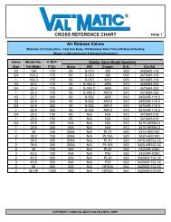
Air Release <strong>Val</strong>ves<br />
Installation Dimensions<br />
WATER <strong>AIR</strong> RELEASE <strong>VALVES</strong><br />
Inlet<br />
Size<br />
Outlet<br />
Size<br />
Model<br />
Number<br />
CWP<br />
PSI<br />
Orifice Size<br />
Dimensions<br />
A B<br />
1/2” NPT 1/2” NPT 15A* 175 1/16” 4 3/4” 5 1/4”<br />
3/4” NPT 1/2” NPT 15A.2* 175 1/16” 4 3/4” 5 1/4”<br />
1” NPT 1/2” NPT 15A.3* 175 1/16” 4 3/4” 5 1/4”<br />
1” NPT 1/2” NPT 22.3* 175 3/32” 5 1/8” 6”<br />
1/2” - 3/4” NPT 1/2” NPT 22.4* 175 3/32” 5 1/8” 6”<br />
1/2” NPT 1/2” NPT 22.7* 300 1/16” 5 1/8” 6”<br />
1/2” - 1” NPT 1/2” NPT 22.9* 300 1/16” 5 1/8” 6”<br />
3/4” - 1” NPT 1/2” NPT 25.5* 150 1/8” 6 1/8” 7”<br />
3/4” - 1” NPT 1/2” NPT 25.6* 300 3/32” 6 1/8” 7”<br />
1” NPT 1/2” NPT 38* 150 3/16” 7” 10”<br />
1” NPT 1/2” NPT 38HP* 500 1/8” 7” 10”<br />
2” NPT 1/2” NPT 38.2* 150 3/16” 7” 10”<br />
1” NPT 1/2” NPT 38.5* 300 5/32” 7” 10”<br />
2” NPT 1/2” NPT 38.6* 300 5/32” 7” 10”<br />
2” NPT 1” NPT 45* 150 23/64” 9 1/2” 12 1/4”<br />
2” NPT 1” NPT 45HP* 400 3/16” 9 1/2” 12 1/4”<br />
3” NPT 1” NPT 45.2* 150 23/64” 9 1/2” 12 1/4”<br />
2” NPT 1” NPT 45.5* 300 7/32” 9 1/2” 12 1/4”<br />
3” NPT 1” NPT 45.6* 300 7/32” 9 1/2” 12 1/4”<br />
2” NPT 1” NPT 50* 500 7/32” 10 7/8” 13”<br />
2” NPT 1” NPT 50HP* 1000 1/8” 10 7/8” 13”<br />
6” 125lb Flg 1” NPT 61* 150 1” 18 3/4” 22”<br />
*NSF/ANSI 61 Certified UL Listed/FM Approved<br />
WASTEWATER <strong>AIR</strong> RELEASE <strong>VALVES</strong><br />
Inlet<br />
Size<br />
Outlet<br />
Size<br />
Model<br />
Number<br />
CWP<br />
PSI<br />
Orifice Size<br />
Dimensions<br />
A B<br />
2” NPT 1/2” NPT 48A 150 3/16” 7” 15 5/16”<br />
3” NPT 1/2” NPT 48A.2 150 3/16” 7” 15 5/16”<br />
2” NPT 1/2” NPT 48A.4 75 5/16” 7” 15 5/16”<br />
3” NPT 1/2” NPT 48A.5 75 5/16” 7” 15 5/16”<br />
2” NPT 1” NPT 49A 150 7/16” 9 1/2” 17 9/16”<br />
3” NPT 1” NPT 49A.2 150 7/16” 9 1/2” 17 9/16”<br />
2” NPT 1” NPT 49A.4 75 1/2” 9 1/2” 17 9/16”<br />
3” NPT 1” NPT 49A.5 75 1/2” 9 1/2” 17 9/16”<br />
4” NPT 1” NPT 49A.6 75 1/2” 9 1/2” 17 9/16”<br />
A<br />
15A - 50HP<br />
Air Release <strong>Val</strong>ve<br />
A<br />
61<br />
Air Release <strong>Val</strong>ve<br />
A<br />
48A - 49A.6<br />
Wastewater Air<br />
Release <strong>Val</strong>ves<br />
B<br />
B<br />
B<br />
13
14<br />
Operational Highlights:<br />
Air/Vacuum <strong>Val</strong>ves<br />
Exhausts large quantities of air at system start-up<br />
Provides pipeline vacuum protection<br />
Responds to loss of pressure during power failures, line breaks<br />
<strong>and</strong> intentional drainage<br />
Product Features:<br />
Unconditionally guaranteed stainless steel floats<br />
Stainless steel 316 internal trim<br />
Exclusive high/low pressure resilient seating<br />
Full pipe size inlets <strong>and</strong> outlets provide maximum protection<br />
Non-clog design eliminates backwashing<br />
Optional Accessories:<br />
Outlet hood with screen (prevents debris from entering valves)<br />
Flanged outlets on sizes 8 inch & smaller<br />
Ball, plug, <strong>and</strong> butterfly isolation valves (allows valve maintenance)<br />
Inflow Preventer on outlet (stops flood water <strong>and</strong> resulting<br />
contamination from entering pipeline)<br />
Backwash kit (for severe wastewater applications)<br />
MATERIALS OF CONSTRUCTION<br />
COMPONENT STANDARD OPTIONAL<br />
Body <strong>and</strong> Cover<br />
Cast Iron ASTM A126 Class B<br />
Class 125 <strong>and</strong> 250<br />
Clean Water*<br />
Ductile Iron ASTM A536 Grade 65-45-12<br />
Stainless Steel ASTM A351 Grade CF8M<br />
Trim Type 316 Stainless Steel -<br />
Coating Universal Alkyd Primer (external) Non-Stick Fusion Bonded Epoxy (internal & external)<br />
FLOW CAPACITY OF <strong>AIR</strong>/VACUUM <strong>VALVES</strong><br />
*<br />
Wastewater
Inlet<br />
Size<br />
Outlet<br />
Size<br />
Air/Vacuum <strong>Val</strong>ves<br />
Installation Dimensions<br />
WATER <strong>AIR</strong>/VACUUM <strong>VALVES</strong><br />
Model<br />
Number<br />
CWP<br />
PSI<br />
Dimensions<br />
A B<br />
1/2” NPT 1/2” NPT 100S 300 6 1/8” 7”<br />
1” NPT 1” NPT 101S 300 7” 9 1/2”<br />
2” NPT 2” NPT 102S 300 9 1/2” 12”<br />
3” NPT 3” NPT 103S 300 9 1/2” 12”<br />
4” Flg 4” NPT<br />
6” Flg 6” NPT<br />
8” Flg 8” NPT<br />
10” Flg 10” Flg<br />
12” Flg 12” Flg<br />
14” Flg 14” Flg<br />
16” Flg 16” Flg<br />
20” Flg 20” Flg<br />
Inlet<br />
Size<br />
Outlet<br />
Size<br />
104S<br />
154S<br />
106S<br />
156S<br />
108S<br />
158S<br />
110F<br />
160F<br />
112F<br />
162F<br />
114F<br />
164F<br />
116F<br />
166F<br />
120F<br />
170F<br />
125lb - 150<br />
250lb - 300<br />
125lb - 150<br />
250lb - 300<br />
125lb - 150<br />
250lb - 300<br />
125lb - 150<br />
250lb - 300<br />
125lb - 150<br />
250lb - 300<br />
125lb - 150<br />
250lb - 300<br />
125lb - 150<br />
250lb - 300<br />
125lb - 150<br />
250lb - 300<br />
WASTEWATER <strong>AIR</strong>/VACUUM <strong>VALVES</strong><br />
Model<br />
Number<br />
CWP<br />
PSI<br />
12” 20 3/4”<br />
14” 18 5/8”<br />
17 1/4” 21 5/8”<br />
20” 26”<br />
24” 31”<br />
27” 34”<br />
30 1/2” 34”<br />
38 1/4” 36 1/4”<br />
Dimensions<br />
A B<br />
2” NPT 1” NPT 301A 150 7” 15 1/16”<br />
2” NPT 2” NPT 302A 150 9 1/2” 17 7/16”<br />
3” NPT 3” NPT 303A 150 9 1/2” 17 7/16”<br />
4” Flg 4” NPT 304 150 11 1/2” 36 1/2”<br />
6” Flg 6” NPT 306 150 14” 36 1/2”<br />
8” Flg 8” NPT 308 150 17 1/4” 40 1/8”<br />
A<br />
100S - 103S<br />
Air/Vacuum <strong>Val</strong>ves<br />
A<br />
104S - 170F<br />
Air/Vacuum <strong>Val</strong>ves<br />
A<br />
301A - 308<br />
Wastewater Air/Vacuum <strong>Val</strong>ves<br />
B<br />
B<br />
B<br />
15
16<br />
Operational Highlights:<br />
Combination Air <strong>Val</strong>ves<br />
Provides the functions of both Air Release <strong>and</strong> Air/Vacuum <strong>Val</strong>ves<br />
Exhausts large quantities of air at system start-up<br />
Releases air pockets during system operation<br />
Provides pipeline vacuum protection<br />
Product Features:<br />
Single body incorporates both features within one valve<br />
– More compact <strong>and</strong> economical<br />
Dual body consists of two independent valves<br />
– Allows individual maintenance while still<br />
protecting the pipeline<br />
–Wider range of sizing options<br />
Inlets <strong>and</strong> outlets are equal to full nominal size<br />
Unconditionally guaranteed stainless steel floats<br />
Stainless steel 316 internal trim<br />
Non-clog design eliminates backwashing<br />
Exclusive high/low pressure resilient seating<br />
Optional Accessories:<br />
Outlet hood with screen (prevents debris from entering valves)<br />
Ball, plug <strong>and</strong> butterfly isolation valves (allows valve maintenance)<br />
Inflow Preventer on outlet (stops flood water <strong>and</strong> resulting<br />
contamination from entering pipeline)<br />
Backwash kit (for severe wastewater applications)<br />
MATERIALS OF CONSTRUCTION<br />
COMPONENT STANDARD OPTIONAL<br />
Body <strong>and</strong> Cover<br />
Cast Iron ASTM A126 Class B<br />
Class 125 <strong>and</strong> 250<br />
Clean Water*<br />
Ductile Iron ASTM A536 Grade 65-45-12<br />
Stainless Steel ASTM A351 Grade CF8M<br />
Trim Type 316 Stainless Steel -<br />
Coating Universal Alkyd Primer (external) Non-Stick Fusion Bonded Epoxy (internal & external)<br />
FLOW CAPACITY OF COMBINATION <strong>AIR</strong> <strong>VALVES</strong><br />
*<br />
Wastewater
Inlet<br />
Size<br />
Combination Air <strong>Val</strong>ves<br />
Installation Dimensions<br />
WATER COMBINATION <strong>AIR</strong> <strong>VALVES</strong> (SINGLE BODY)<br />
Outlet<br />
Size<br />
Model<br />
Number<br />
CWP<br />
PSI<br />
Orifice Size<br />
Dimensions<br />
A B<br />
1” NPT 1” NPT 201C.2 300 5/64” 11 3/8” 10 1/2”<br />
2” NPT 2” NPT 202C.2 300 3/32” 14” 13”<br />
3” NPT 3” NPT 203C.2 300 3/32” 16” 15”<br />
3” 125lb Flg 3” NPT 203C.14 150 3/32” 16” 16 3/4”<br />
3” 250lb Flg 3” NPT 203C.15 300 3/32” 16” 17 1/4”<br />
4” NPT 4” NPT 204C.2 300 3/32” 18 1/2” 17”<br />
4” 125lb Flg 4” NPT 204C.14 150 3/32” 18 1/2” 19 3/4”<br />
4” 250lb Flg 4” NPT 204C.15 300 3/32” 18 1/2” 20 1/4”<br />
6” 125lb Flg 6” NPT 206C 150 3/8” 21” 20 1/4”<br />
6” 250lb Flg 6” NPT 256C 300 7/32” 21” 20 1/4”<br />
8” 125lb Flg 8” NPT 208C 150 3/8” 25” 23 1/2”<br />
8” 250lb Flg 8” NPT 258C 300 7/32” 25” 23 1/2”<br />
WASTEWATER COMBINATION <strong>AIR</strong> <strong>VALVES</strong> (SINGLE BODY)<br />
Inlet<br />
Size<br />
Outlet<br />
Size<br />
Model<br />
Number<br />
CWP<br />
PSI<br />
Orifice Size<br />
Dimensions<br />
A B<br />
2” NPT 1” NPT 801A 150 1/8” 7” 14 15/16”<br />
2” NPT 2” NPT 802A 150 9/64” 9 1/2” 18 1/16”<br />
3” NPT 3” NPT 803A 150 11/64” 11” 23 1/2”<br />
4” NPT 4” NPT 804 150 11/64” 11” 23 1/2”<br />
Surge-Suppression Air <strong>Val</strong>ves <strong>and</strong> Isolation <strong>Val</strong>ves in a pump discharge application.<br />
A<br />
201C.2 - 204C.15<br />
Single Body Combination<br />
Air <strong>Val</strong>ves<br />
A<br />
206C - 258C<br />
Single Body<br />
Combination Air <strong>Val</strong>ves<br />
A<br />
B<br />
801A - 804<br />
Wastewater<br />
Single Body Combination<br />
Air <strong>Val</strong>ves<br />
B<br />
B<br />
17
18<br />
A<br />
101S/22.9 - 103S/22.9<br />
Dual Body Combination<br />
Air <strong>Val</strong>ves<br />
A<br />
104S/38 - 166F/45.5<br />
Dual Body Combination<br />
Air <strong>Val</strong>ves<br />
B<br />
B<br />
Combination Air <strong>Val</strong>ves<br />
Installation Dimensions<br />
Inlet<br />
Size<br />
WATER COMBINATION <strong>AIR</strong> <strong>VALVES</strong> (DUAL BODY)<br />
Outlet<br />
Size<br />
Model<br />
Number<br />
CWP<br />
PSI<br />
Orifice Size<br />
Dimensions<br />
A B<br />
1” NPT 1” NPT 101S/22.9 300 1/16” 7 7/8” 15 5/8”<br />
2” NPT 2” NPT 102S/22.9 300 1/16” 10 1/4” 17 7/8”<br />
3” NPT 3” NPT 103S/22.9 300 1/16” 10 1/4” 18 1/4”<br />
Inlet<br />
Size<br />
WATER COMBINATION <strong>AIR</strong> <strong>VALVES</strong> (DUAL BODY)<br />
Outlet<br />
Size<br />
Air/Vacuum<br />
4” Flg 4” NPT<br />
6” Flg 6” NPT<br />
8” Flg 8” NPT<br />
8” Flg 8” NPT<br />
10” Flg 10” Flg<br />
10” Flg 10” Flg<br />
12” Flg 12” Flg<br />
12” Flg 12” Flg<br />
14” Flg 14” Flg<br />
14” Flg 14” Flg<br />
16” Flg 16” Flg<br />
16” Flg 16” Flg<br />
Model<br />
Number<br />
104S/38<br />
154S/38.5<br />
106S/38<br />
156S/38.5<br />
108S/38<br />
158S/38.5<br />
108S/45<br />
158S/45.5<br />
110F/38<br />
160F/38.5<br />
110F/45<br />
160F/45.5<br />
112F/38<br />
162F/38.5<br />
112F/45<br />
162F/45.5<br />
114F/38<br />
164F/38.5<br />
114F/45<br />
164F/45.5<br />
116F/38<br />
166F/38.5<br />
116F/45<br />
166F/45.5<br />
CWP<br />
PSI<br />
125lb - 150<br />
250lb - 300<br />
125lb - 150<br />
250lb - 300<br />
125lb - 150<br />
250lb - 300<br />
125lb - 150<br />
250lb - 300<br />
125lb - 150<br />
250lb - 300<br />
125lb - 150<br />
250lb - 300<br />
125lb - 150<br />
250lb - 300<br />
125lb - 150<br />
250lb - 300<br />
125lb - 150<br />
250lb - 300<br />
125lb - 150<br />
250lb - 300<br />
125lb - 150<br />
250lb - 300<br />
125lb - 150<br />
250lb - 300<br />
Orifice Size<br />
Air Release<br />
3/16”<br />
5/32”<br />
3/16”<br />
5/32”<br />
3/16”<br />
5/32”<br />
23/64”<br />
7/32”<br />
3/16”<br />
5/32”<br />
23/64”<br />
7/32”<br />
3/16”<br />
5/32”<br />
23/64”<br />
7/32”<br />
3/16”<br />
5/32”<br />
23/64”<br />
7/32”<br />
3/16”<br />
5/32”<br />
23/64”<br />
7/32”<br />
Dimensions<br />
A B<br />
21” 22”<br />
24” 23”<br />
27” 26”<br />
30” 29”<br />
30” 28”<br />
33” 31”<br />
33” 32”<br />
37” 34”<br />
36” 34”<br />
40” 36”<br />
39” 34”<br />
44” 37”
Inlet<br />
Size<br />
Combination Air <strong>Val</strong>ves<br />
Installation Dimensions<br />
WASTEWATER COMBINATION <strong>AIR</strong> <strong>VALVES</strong> (DUAL BODY)<br />
Outlet<br />
Size<br />
Model<br />
Number<br />
CWP<br />
PSI<br />
Orifice<br />
Size<br />
Dimensions<br />
A B<br />
2” NPT 1” NPT 48A/301A 150 3/16” 20 5/16” 20 5/16”<br />
2” NPT 1” NPT 49A/301A 150 7/16” 19 1/2” 22 3/4”<br />
2” NPT 2” NPT 48A/302A 150 3/16” 20 3/4” 25 3/4”<br />
2” NPT 2” NPT 49A/302A 150 7/16” 20 3/4” 22 3/4”<br />
3” NPT 3” NPT 48A/303A 150 3/16” 21 1/2” 28 1/4”<br />
3” NPT 3” NPT 49A/303A 150 7/16” 21 1/2” 24 3/4”<br />
Inlet<br />
Size<br />
WASTEWATER COMBINATION <strong>AIR</strong> <strong>VALVES</strong> (DUAL BODY)<br />
Outlet<br />
Size<br />
Model<br />
Number<br />
CWP<br />
PSI<br />
Orifice<br />
Size<br />
Dimensions<br />
A B<br />
4” Flg 4” NPT 48A/304 150 3/16” 20 3/4” 36 1/2”<br />
4” Flg 4” NPT 49A/304 150 7/16” 20 3/4” 36 1/2”<br />
6” Flg 6” NPT 48A/306 150 3/16” 23 1/4” 36 1/2”<br />
6” Flg 6” NPT 49A/306 150 7/16” 23 1/4” 36 1/2”<br />
8” Flg 8” NPT 48A/308 150 3/16” 25 3/4” 41 1/4”<br />
8” Flg 8” NPT 49A/308 150 7/16” 27 1/2” 41 1/4”<br />
Air <strong>Val</strong>ves are commonly found in plant service as well as pipelines for efficiency <strong>and</strong><br />
protection. The model shown above is a 48A/308 with flanged outlet <strong>and</strong> optional<br />
Cam-Centric® Plug <strong>Val</strong>ve for isolation <strong>and</strong> maintenance.<br />
A<br />
A<br />
48A/301A - 49A/303A<br />
Dual Body Wastewater<br />
Combination Air <strong>Val</strong>ves<br />
48A/304 - 49A/308<br />
Dual Body Wastewater<br />
Combination Air <strong>Val</strong>ves<br />
B<br />
B<br />
19
20<br />
Operational Highlights:<br />
Provides full vacuum protection for the pipeline<br />
Provides slow closure suppressing surge in the pipeline<br />
Minimizes water blow-by during Air <strong>Val</strong>ve closure<br />
Allows the use of smaller valve size by utilizing a maximum<br />
sizing differential pressure of 5 psig<br />
Releases entrained air while pipeline is operating to maintain<br />
pumping efficiency<br />
Fully complies with AWWA C512 <strong>and</strong> NSF 61<br />
Surge-Suppression Air <strong>Val</strong>ve Features:<br />
Restrictor disc provides regulated exhaust to limit secondary<br />
surges during column separation<br />
Ability to adjust air exhaust for greater surge suppression<br />
Provides full vacuum flow port<br />
Optional Accessories:<br />
MATERIALS OF CONSTRUCTION<br />
COMPONENT STANDARD OPTIONAL<br />
Body Cast Iron ASTM A126 Class B Ductile Iron ASTM A536 Grade 65-45-12<br />
Trim<br />
Surge-Suppression Air <strong>Val</strong>ves<br />
Outlet hood with screen (prevents debris from entering valves)<br />
Ball <strong>and</strong> butterfly isolation valves (allows valve maintenance)<br />
Inflow Preventer on outlet (stops flood water <strong>and</strong> resulting<br />
contamination from entering pipeline)<br />
Backwash kit (for severe wastewater applications)<br />
Type 316 Stainless Steel (Air <strong>Val</strong>ve)<br />
Bronze ASTM B584 C83600 (Reg. Exh. Dev.)*<br />
Stainless Steel ASTM A351 Grade CF8M<br />
(Reg. Exh. Dev.)*<br />
Exterior Coating Universal Primer (external) Non-Stick Fusion Bonded Epoxy (internal & external)<br />
*(Reg. Exh. Dev.) = Regulated-Exhaust Device<br />
Clean Water* Wastewater<br />
FLOW CAPACITY OF SURGE-SUPPRESSION <strong>AIR</strong> <strong>VALVES</strong><br />
*
Surge-Suppression Air <strong>Val</strong>ves<br />
Installation Dimensions<br />
WATER SURGE-SUPPRESSION <strong>AIR</strong> <strong>VALVES</strong> (SINGLE BODY)<br />
Inlet<br />
Size<br />
Outlet<br />
Size<br />
Model Number<br />
CWP<br />
PSI<br />
Orifice<br />
Size<br />
Dimensions<br />
A B<br />
1” NPT 1” NPT 201CSS 250 5/64” 11 3/8” 13 5/8”<br />
2” NPT 2” NPT 202CSS 250 3/32” 14” 17 1/4”<br />
3” 125lb Flg 3” NPT 203CSS 300 3/32” 16” 22 3/4”<br />
3” 250lb Flg 3” NPT 253CSS 300 3/32” 16” 22 3/4”<br />
4” 125lb Flg 4” NPT 204CSS 300 3/32” 18 1/2” 27”<br />
4” 250lb Flg 4” NPT 254CSS 300 3/32” 18 1/2” 27”<br />
6” 125lb Flg 6” NPT 206CSS 150 3/8” 21” 30”<br />
8” 250lb Flg 8” NPT 256CSS 300 7/32” 21” 30”<br />
6” 125lb Flg 6” NPT 208CSS 150 3/8” 25” 36”<br />
8” 250lb Flg 8” NPT 258CSS 300 7/32” 25” 36”<br />
WATER SURGE-SUPPRESSION <strong>AIR</strong> <strong>VALVES</strong> (DUAL BODY)<br />
Inlet*<br />
Size<br />
Outlet**<br />
Size<br />
Model Number<br />
CWP<br />
PSI<br />
Orifice<br />
Size<br />
Dimensions<br />
A B<br />
4” 125lb Flg 4” NPT 104SS/38 150 3/16” 21” 29”<br />
4” 250lb Flg 4” NPT 154SS/38.5 300 5/32” 21” 29”<br />
6” 125lb Flg 6” NPT 106SS/38 150 3/16” 22 1/2” 33”<br />
6” 250lb Flg 6” NPT 156SS/38.5 300 5/32” 22 1/2” 33”<br />
8” 125lb Flg 8” NPT 108SS/38 150 3/16” 27” 38”<br />
8” 250lb Flg 8” NPT 158SS/38.5 300 5/32” 27” 38”<br />
10” 125lb Flg 10” Flg 110FSS/45 150 23/64” 33” 47”<br />
10” 250lb Flg 10” Flg 160FSS/45.5 300 7/32” 33” 47”<br />
12” 125lb Flg 12” Flg 112FSS/45 150 23/64” 37” 48 1/2”<br />
12” 250lb Flg 12” Flg 162FSS/45.5 300 7/32” 37” 48 1/2”<br />
* For sizes 14” - 20” Consult Factory<br />
**All outlet flanges are class 125 lb.<br />
WASTEWATER SURGE-SUPPRESSION <strong>AIR</strong> <strong>VALVES</strong> (SINGLE BODY)<br />
Inlet<br />
Size<br />
Outlet<br />
Size<br />
Model Number<br />
CWP<br />
PSI<br />
Orifice<br />
Size<br />
Dimensions<br />
A B<br />
2” NPT 1” NPT 801SS 150 1/8” 7” 18”<br />
2” NPT 2” NPT 802SS 150 9/64” 9 1/2” 23”<br />
3” NPT 3” NPT 803SS 150 11/64” 11” 33”<br />
4” NPT 4” NPT 804SS 150 11/64” 11” 34”<br />
203CSS - 258CSS<br />
Surge-Suppression Single Body<br />
Air <strong>Val</strong>ves<br />
104SS/38 - 162FSS/45.5<br />
Surge-Suppression Dual Body<br />
Air <strong>Val</strong>ves<br />
A<br />
A<br />
801SS - 804SS<br />
Surge-Suppression Single Body<br />
Air <strong>Val</strong>ves<br />
A<br />
B<br />
B<br />
B<br />
21
22<br />
Operational Highlights:<br />
Well Service Air <strong>Val</strong>ves<br />
Regulates the exhaust of air on pump start-up<br />
Admits air to protect pump <strong>and</strong> mechanical seals<br />
Protects against air-related surges on pump start-up<br />
Fully complies with AWWA C512 <strong>and</strong> NSF 61<br />
Product Features:<br />
Unconditionally guaranteed 316 stainless steel floats<br />
Inlets <strong>and</strong> outlets are equal to full nominal pipe area<br />
1/2" - 3" equipped with Dual Port Throttling Device<br />
4" <strong>and</strong> larger equipped with Regulated-Exhaust Device mounted on<br />
the inlet<br />
Dual Port Throttling Device:<br />
Adjustable discharge outlet provides regulated air exhaust<br />
Allows air to enter the system on pump shut down through an<br />
unrestricted independent vacuum port<br />
Regulated-Exhaust Device:<br />
Retrictor disc provides regulated exhaust to limit pump column surges<br />
Ability to adjust air exhaust for greater surge suppression<br />
Provides full vacuum flow port<br />
MATERIALS OF CONSTRUCTION<br />
COMPONENT STANDARD OPTIONAL<br />
Body <strong>and</strong> Cover<br />
Trim<br />
Cast Iron ASTM A126 Class B<br />
Class 125 <strong>and</strong> 250<br />
Type 316 Stainless Steel (Air <strong>Val</strong>ve)<br />
Bronze ASTM B584 C83600 (Reg. Exh. Dev.)*<br />
Ductile Iron ASTM A536 Grade 65-45-12<br />
Stainless Steel ASTM A351 Grade CF8M<br />
Coating Universal Alkyd Primer (external) Non-Stick Fusion Bonded Epoxy (internal & external)<br />
*(Reg. Exh. Dev.) = Regulated-Exhaust Device<br />
1 - 3 inch<br />
WELL SERVICE <strong>AIR</strong> VALVE SIZING<br />
VALVE NO HEAD PUMP MODEL NUMBER<br />
SIZE CAPACITY, GPM 150 PSI MODEL 300 PSI MODEL<br />
1/2” 0 - 350 100ST<br />
1” 351 - 1,350 101ST<br />
2” 1,351 - 4,000 102ST<br />
3” 4,001 - 7,000 103ST<br />
4” 7,001 - 11,000 104SS 154SS<br />
6” 11,001 - 24,000 106SS 156SS<br />
8” 24,001 - 50,000 108SS 158SS<br />
10” 50,001 - 70,000 110FSS 160FSS<br />
12” 70,001 - 110,000 112FSS 162FSS<br />
-<br />
4 inch & larger
Inlet<br />
Size<br />
Well Service Air <strong>Val</strong>ve<br />
with Dual Port Throttling Device<br />
Outlet<br />
Size<br />
Model<br />
Number<br />
CWP<br />
PSI<br />
Dimensions<br />
A B<br />
1/2” NPT 1/2” NPT 100ST 300 6 1/8” 11 3/4”<br />
1” NPT 1” NPT 101ST* 300 7” 14 3/4”<br />
2” NPT 2” NPT 102ST* 300 9 1/2” 20 1/8”<br />
3” NPT 3” NPT 103ST* 300 9 1/2” 22 1/8”<br />
*UL Listed for fire pump service<br />
Well Service Air <strong>Val</strong>ve with Regulated-Exhaust Device<br />
Inlet<br />
Size<br />
Well Service Air <strong>Val</strong>ves<br />
Installation Dimensions<br />
Outlet<br />
Size<br />
Model<br />
Number<br />
CWP<br />
PSI<br />
Dimensions<br />
A B<br />
4” 125lb Flg 4” NPT 104SS 150 11 1/2” 22 3/4”<br />
4” 250lb Flg 4” NPT 154SS 300 11 1/2” 22 3/4”<br />
6” 125lb Flg 6” NPT 106SS 150 14” 28 1/2”<br />
6” 250lb Flg 6” NPT 156SS 300 14” 28 1/2”<br />
8” 125lb Flg 8” NPT 108SS 150 17 1/4” 35 5/16”<br />
8” 250lb Flg 8” NPT 158SS 300 17 1/4” 35 5/16”<br />
10” 125lb Flg 10” 125lb Flg 110FSS 150 20 1/4” 40 1/16”<br />
10” 250lb Flg 10” 125lb Flg 160FSS 300 20 1/4” 40 1/16”<br />
12” 125lb Flg 12” 125lb Flg 112FSS 150 24” 44 5/16”<br />
12” 250lb Flg 12” 125lb Flg 162FSS 300 24” 44 5/16”<br />
3” Well Service Air <strong>Val</strong>ve on Vertical Pump discharge.<br />
A<br />
100ST - 103ST<br />
Well Service Air <strong>Val</strong>ves with<br />
Dual Port Throttling Device<br />
A<br />
104SS - 162FSS<br />
Well Service Air <strong>Val</strong>ves<br />
with Regulated-Exhaust Device<br />
B<br />
B<br />
23
24<br />
Operational Highlights:<br />
Provides vacuum protection for pipelines <strong>and</strong> tanks<br />
Cushions surges related to column separation<br />
Opens in response to a 0.25 psi vacuum<br />
Product Features:<br />
Resilient seals provide drop tight seating<br />
Full flow areas provide maximum vacuum protection<br />
Vacuum Breaker <strong>Val</strong>ves<br />
Optional Accessories:<br />
Hood with inlet screen (prevents debris from entering valves)<br />
Air Release <strong>Val</strong>ve (slowly releases air to prevent violent<br />
rejoining of water columns)<br />
Inflow Preventer on outlet (stops flood water <strong>and</strong> resulting<br />
contamination from entering pipeline)<br />
SEAT DETAIL<br />
BODY<br />
SEA T<br />
SEA TED<br />
POSITION<br />
UNSEA TED<br />
POSITION<br />
MATERIALS OF CONSTRUCTION<br />
COMPONENT STANDARD OPTIONAL<br />
Body <strong>and</strong> Cover<br />
Cast Iron ASTM A126 Class B<br />
Class 125 <strong>and</strong> 250<br />
Ductile Iron ASTM A536 Grade 65-45-12<br />
Trim Bronze, ASTM B584, C83600 Stainless Steel ASTM A351 Grade CF8M<br />
Coating Universal Alkyd Primer Non-Stick Fusion Bonded Epoxy (internal & external)<br />
DISC<br />
RESILIENT SEAL<br />
VENTING CAPACITY FOR VACUUM BREAKERS<br />
Vacuum Breaker with optional<br />
Air Release <strong>Val</strong>ve
THREADED VACUUM BREAKER <strong>AIR</strong> VALVE<br />
INLET OUTLET MODEL NUMBER CWP<br />
A<br />
Dimensions<br />
B<br />
1/2” NPT 1/2” NPT 100VB 300 6 1/8” 8”<br />
1” NPT 1” NPT 101VB 300 7” 11”<br />
2” NPT 2” NPT 102VB 300 9 1/2” 14”<br />
3” NPT 3” NPT 103VB 300 9 1/2” 14 1/2”<br />
FLANGED VACUUM BREAKER WITH <strong>AIR</strong> RELEASE VALVE<br />
INLET MODEL NUMBER MODEL NUMBER Dimensions<br />
SIZE* 125lb CLASS (CWP) 250lb CLASS (CWP) A B<br />
3 1803VB/38 150 1853VB/38.5 300 16” 15”<br />
4 1804VB/38 150 1854VB/38.5 300 17 3/8” 15 7/8”<br />
5 1805VB/38 150 1855VB/38.5 300 18 3/4” 16 3/4”<br />
6 1806VB/38 150 1856VB/38.5 300 20” 17 1/4”<br />
8 1808VB/38 150 1858VB/38.5 300 22 3/4” 18 1/4”<br />
10 1810VB/38 150 1860VB/38.5 300 25 5/8” 19 3/4”<br />
12 1812VB/38 150 1862VB/38.5 300 28 3/4” 19 1/8”<br />
INLET<br />
SIZE*<br />
*For sizes 14” - 42” consult factory<br />
Vacuum Breaker <strong>Val</strong>ves<br />
Installation Dimensions<br />
FLANGED VACUUM BREAKER <strong>AIR</strong> VALVE<br />
INLET MODEL NUMBER MODEL NUMBER Dimensions<br />
SIZE* 125lb CLASS (CWP) 250lb CLASS (CWP) A B<br />
2 1802VB 200 1852VB 400 7” 8 1/2”<br />
2.5 1825VB 200 1875VB 400 7” 8 1/2”<br />
3 1803VB 200 1853VB 400 7 1/2” 10”<br />
4 1804VB 200 1854VB 400 9” 11 1/4”<br />
5 1805VB 200 1855VB 400 10” 13”<br />
6 1806VB 200 1856VB 400 11” 14 1/4”<br />
8 1808VB 200 1858VB 400 13 1/2” 18”<br />
10 1810VB 200 1860VB 400 16” 21 1/2”<br />
12 1812VB 200 1862VB 400 19” 21 3/8”<br />
FLANGED VACUUM BREAKER WITH <strong>AIR</strong> RELEASE VALVE<br />
FOR WASTEWATER SERVICE<br />
MODEL<br />
NUMBER<br />
MODEL NUMBER with<br />
Air Release <strong>Val</strong>ve<br />
Dimensions<br />
125lb CLASS (CWP) A B C D<br />
3 1803VBS 1803VBS/48A 200 16” 20 5/16” 7 1/2” 10”<br />
4 1804VBS 1804VBS/48A 200 17 3/8” 21 5/16” 9” 11 1/4”<br />
5 1805VBS 1805VBS/48A 200 18 3/4” 22 1/16” 10” 13”<br />
6 1806VBS 1806VBS/48A 200 20” 22 9/16” 11” 14 1/4”<br />
8 1808VBS 1808VBS/48A 200 22 3/4” 23 9/16” 13 1/2” 18”<br />
10 1810VBS 1810VBS/48A 200 25 5/8” 25 1/16” 16” 21 1/2”<br />
12 1812VBS 1812VBS/48A 200 28 3/4” 24 7/16” 19” 21 3/8”<br />
D<br />
100VB-103VB<br />
Vacuum Breaker <strong>Val</strong>ves<br />
A<br />
1803VB/38 - 1862VB/38.5<br />
Vacuum Breaker <strong>Val</strong>ves<br />
C<br />
A<br />
A<br />
1802VB-1862VB<br />
Vacuum Breaker <strong>Val</strong>ves<br />
A<br />
1803VBS - 1812VBS/48A<br />
Vacuum Breaker <strong>Val</strong>ves<br />
B<br />
B<br />
B<br />
B<br />
25
26<br />
Vacuum Priming <strong>Val</strong>ves<br />
Operational Highlights:<br />
Allows the extraction of air from the pump housing <strong>and</strong><br />
suction piping<br />
Float rises <strong>and</strong> closes the priming valve to prevent fluid<br />
from flowing into the vacuum priming system<br />
Continues to release air while the pump is running<br />
Product Features:<br />
Specifically designed to prevent fluid leakage<br />
Flow sensitive float<br />
Stainless steel 316 internal trim <strong>and</strong> float<br />
Optional Accessories:<br />
Water Level Control Switch (Mercury-Free)<br />
INLET<br />
SIZE<br />
OUTLET<br />
SIZE<br />
VACUUM PRIMING <strong>VALVES</strong><br />
MODEL CWP ORIFICE Dimensions<br />
NO. PSI SIZE A B C<br />
2” BALL<br />
VALVE<br />
2” N.P .T .<br />
PIPING<br />
V ACUUM LINE<br />
T O PRIMING SYSTEM<br />
SUCTION<br />
PIPE<br />
MATERIALS OF CONSTRUCTION<br />
COMPONENT STANDARD OPTIONAL<br />
Body <strong>and</strong> Cover Cast Iron ASTM A126, Class B<br />
2” NPT 1/2” NPT 38P 150 3/16” 16 1/4” 15 5/16” 7”<br />
2” NPT 1/2” NPT 38P.2 75 5/16” 16 1/4” 15 5/16” 7”<br />
2” NPT 1” NPT 45P 150 23/64” 17 1/2” 17 9/16” 9 1/2”<br />
2” NPT 1” NPT 45P.3 75 1/2” 17 1/2” 17 9/16” 9 1/2”<br />
2” N.P.T. INLET<br />
1/2” N.P .T .<br />
RECOMMENDED<br />
1/2” N.P .T . OUTLET FOR 38P<br />
1” N.P .T . OUTLET FOR 45P OR 50HP<br />
PRIMING V AL VE<br />
OPTIONAL W A TER LEVEL CONTROL<br />
SWITCH T O INDICA TE LOSS OF PRIME<br />
NOTE: SLOPE UPW ARD FROM<br />
PUM P T O PRIMING V AL VE<br />
Recommended Piping Arrangement<br />
FLOW<br />
Vacuum Priming <strong>Val</strong>ve<br />
Ductile Iron ASTM A536 Grade 65-45-12 Stainless Steel<br />
ASTM A351 Grade CF8M<br />
Trim Stainless Steel, Type 316 -<br />
Coating Universal Alkyd Primer (external) Non-Stick Fusion Bonded Epoxy (internal & external)<br />
A<br />
C<br />
38P - 45P.3<br />
Vacuum Priming <strong>Val</strong>ve<br />
with Optional Water Level<br />
Control Switch<br />
B
PROJECT INFORMATION<br />
PROJECT: SAMPLE<br />
OWNER: <strong>Val</strong>matic<br />
ENGINEER: <strong>Val</strong>matic<br />
MEDIA: Water-NSF/ANSI 61 Certified<br />
PIPE MATERIAL: Steel or Stainless<br />
PIPE INSIDE DIAMETER: 47.00<br />
STEEL PIPE THICKNESS: 0.25 in<br />
MAX FLOW RATE: 30,000 GPM<br />
FILL RATE: 12,000 GPM<br />
SELECTED SAFETY FACTOR: 4:1<br />
DIFF.PRES. FOR VAC. SIZING: 2.45 Psi<br />
PIPELINE <strong>AIR</strong> VALVE SAMPLE SCHEDULE<br />
VALVE RATING: 150 Psig (Class 125 Iron)<br />
REVERSE FLOW: No<br />
VALVE SELECTION CRITERIA: Surge-Suppression Air <strong>Val</strong>ves<br />
Station ELEV Excav Description Recommended <strong>Val</strong>ve Size/Model Max Flow Rate<br />
No ft ft Slope CFS<br />
0<br />
1,600<br />
3,200<br />
4,933<br />
6,667<br />
8,400<br />
9,200<br />
11,200<br />
12,000<br />
12,800<br />
13,600<br />
14,400<br />
ELEVATION (FT)<br />
25<br />
20<br />
15<br />
10<br />
5<br />
0<br />
5<br />
10<br />
10<br />
10<br />
10<br />
20<br />
16<br />
2<br />
16<br />
20<br />
20<br />
Air <strong>Val</strong>ve Sizing Software<br />
The <strong>Val</strong>-<strong>Matic</strong> air<strong>Val</strong>ve Sizing program is an easy to<br />
use Windows-based computer program for locating<br />
<strong>and</strong> sizing Air <strong>Val</strong>ves in Water <strong>and</strong> Wastewater<br />
applications.<br />
The pipeline profile data is entered into the program<br />
(Figure 1) which evaluates system data <strong>and</strong><br />
develops sizing criteria such as slope for each<br />
pipeline segment <strong>and</strong> flow rate due to slope. Then<br />
it will recommend valve locations, sizes <strong>and</strong> models<br />
<strong>and</strong> print a valve schedule (Figure 2) <strong>and</strong> prepare a<br />
pipeline profile (Figure 3) for the user. Finally, the<br />
program will save your data for future reference.<br />
The <strong>Val</strong>-<strong>Matic</strong> air<strong>Val</strong>ve Sizing Software is an indispensable,<br />
free resource that allows engineers to<br />
more effectively <strong>and</strong> efficiently design their water<br />
<strong>and</strong> wastewater piping systems. It is available for<br />
download at www.valmatic.com.<br />
0.00<br />
0.00<br />
0.00<br />
0.00<br />
0.00<br />
0.00<br />
0.00<br />
0.00<br />
0.00<br />
0.00<br />
0.00<br />
0.00<br />
1600<br />
Beginning<br />
Long Ascent<br />
High Point<br />
Long Horiz<br />
Long Horiz<br />
Low Point<br />
High Point<br />
Incr in Down-Slope<br />
Low Point<br />
Decr in Up-Slope<br />
High Point<br />
End<br />
3200 4933 6667<br />
No valve necessary<br />
8 IN #108SS Surge-Suppression AV<br />
8 IN #108SS/38 Surge-Suppression AV<br />
2 IN #38.2 Air Release<br />
4 IN #104SS/38 Surge-Suppression AV<br />
No valve necessary<br />
10 IN #110FSS/45 Surge-Suppression AV<br />
8 IN #108SS/38 Surge-Suppression AV<br />
No valve necessary<br />
8 IN #108SS Surge-Suppression AV<br />
8 IN #108SS/38 Surge-Suppression AV<br />
No valve necessary<br />
FIGURE 2<br />
SAMPLE PIPELINE PROFILE<br />
0<br />
0 4000 8000 12000 16000<br />
STATION (FT)<br />
FIGURE 3<br />
9200<br />
11200 12800<br />
13600<br />
FLOW<br />
FIGURE 1<br />
0.00<br />
0.00<br />
0.00<br />
0.00<br />
0.00<br />
0.01<br />
0.01<br />
-0.02<br />
0.02<br />
0.02<br />
0.01<br />
0.00<br />
0.00<br />
84.41<br />
84.41<br />
0.00<br />
0.00<br />
0.00<br />
134.66<br />
95.37<br />
0.00<br />
74.17<br />
85.17<br />
0.00<br />
<strong>AIR</strong> VALVE TYPE<br />
<strong>AIR</strong> RELEASE<br />
<strong>AIR</strong>/VACUUM<br />
COMBINATION<br />
27
Make the change to QUALITY!<br />
Specify V<br />
<strong>Val</strong>-<strong>Matic</strong>’s quality of design <strong>and</strong> meticulous workmanship has set<br />
the st<strong>and</strong>ards by which all others are measured. Quality design<br />
features such as Type 316 stainless steel trim as st<strong>and</strong>ard on Air<br />
Release, Air/Vacuum <strong>and</strong> Combination Air <strong>Val</strong>ves...combined<br />
resilient/metal to metal seating for Silent Check ® <strong>Val</strong>ves...stabilized<br />
components that provide extended life of the Dual Disc ®<br />
Check <strong>Val</strong>ves...high strength <strong>and</strong> wear resistant aluminum bronze<br />
trim as st<strong>and</strong>ard for Tilted Disc ® Check valves...unrestricted full<br />
flow area through Swing-Flex ® Check <strong>Val</strong>ves...heavy duty stainless<br />
steel screened inlet on Sure Seal ® Foot <strong>Val</strong>ves...a Cam-Centric ®<br />
Plug <strong>Val</strong>ve with more requested features than any other eccentric<br />
V<br />
Copyright © 2008 <strong>Val</strong>-<strong>Matic</strong> <strong>Val</strong>ve & Mfg. <strong>Corp</strong>.<br />
ISO 9001:2000 certified company<br />
plug valve, <strong>and</strong> the American-BFV ® Butterfly <strong>Val</strong>ve that provides<br />
a field replaceable seat without the need for special tools. These<br />
features coupled with our attention to detail put <strong>Val</strong>-<strong>Matic</strong> valves<br />
in a class by themselves. The VaultSafe ® family of products included<br />
the FloodSafe Inflow Preventer, FrostSafe ® two-way<br />
damper <strong>and</strong> the VentSafe ® vent pipe security cage.<br />
<strong>Val</strong>-<strong>Matic</strong> is totally committed to providing the highest quality<br />
valves <strong>and</strong> outst<strong>and</strong>ing service to our customers. Complete customer<br />
satisfaction is our goal.<br />
VAL-MATIC VALVE AND MANUFACTURING CORP.<br />
905 RIVERSIDE DRIVE ELMHURST, IL 60126<br />
630-941-7600 FAX: 630-941-8042<br />
www.valmatic.com valves@valmatic.com<br />
<strong>1500</strong>-4/08