
You also want an ePaper? Increase the reach of your titles
YUMPU automatically turns print PDFs into web optimized ePapers that Google loves.
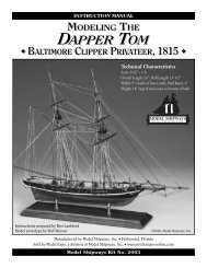
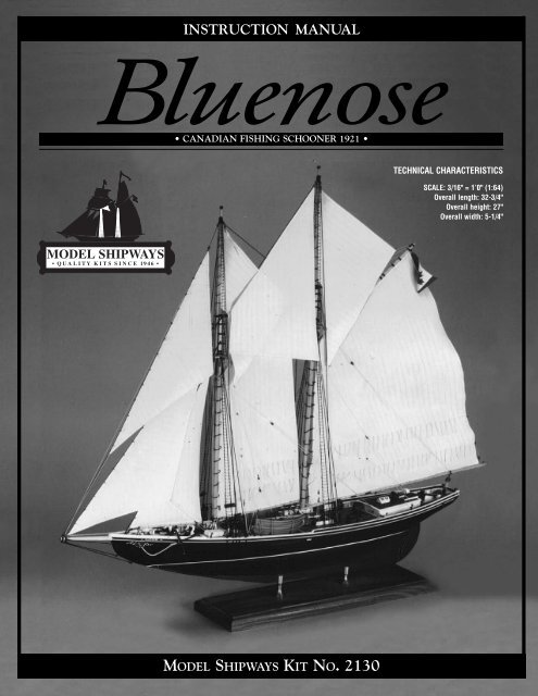
INSTRUCTION MANUAL<br />
<strong>Bluenose</strong><br />
• CANADIAN FISHING SCHOONER 1921 •<br />
MODEL SHIPWAYS KIT NO. 2130<br />
0<br />
TECHNICAL CHARACTERISTICS<br />
SCALE: 3/16" = 1’0" (1:64)<br />
Overall length: 32-3/4"<br />
Overall height: 27"<br />
Overall width: 5-1/4"
By the early 1900s, the fishing schooner had developed<br />
into a fast, efficient vessel. American and Canadian<br />
schooners were similar in design. Both operated on the<br />
Grand Banks off Nova Scotia. They carried 10 or more<br />
small dories from which two-man crews fished.<br />
In the days before refrigeration, fishing schooners had to<br />
be fast, or their catch would spoil before it reached market.<br />
Grand Banks’ schooners were divided into two classes:<br />
those carrying ice as a preservative and staying out two or<br />
three weeks, and the salt bankers that fished until their<br />
hulls were full. The latter made two or three trips a season<br />
and were hauled out in winter.<br />
In the United States, most schooners’ home port was<br />
Gloucester, Massachusetts. These became known as<br />
Gloucester fishermen, or just Gloucestermen. In Canada,<br />
the boats hailed from Nova Scotia.<br />
The Canadian fishing schooner <strong>Bluenose</strong> was designed by<br />
William J. Roué and built in 1920-1921 at the Smith and<br />
Rhuland Shipyard in Lunenburg, Nova Scotia. Launched<br />
26 March 1921, she was 143 feet long, 112 feet at the<br />
waterline, with a beam of 27 feet, and displacement<br />
around 280 tons. She was a salt banker, carrying salt in<br />
her bins rather than ice.<br />
<strong>Bluenose</strong> is famous for beating Gloucestermen in the<br />
International Fishing Schooner Races. She was twice<br />
crowned queen of the Lunenburg fleet, and retains the<br />
record of fastest fishing schooner in Canadian history.<br />
2<br />
Skippers had raced each other for years, but the friendly<br />
rivalry took on its international flavor in 1920. H. W.<br />
Dennis of the Halifax Herald and Halifax Evening Mail<br />
offered a $4,000 prize and the Dennis Cup to the schooner<br />
winning a series of 40-mile races. His motive was to preserve<br />
the fishing schooner while stimulating development<br />
of faster designs.<br />
The first regatta was won by the Gloucesterman Esperanto<br />
over the Canadian Delawanna. Seeking retribution, Captain<br />
Angus Walters formed a Canadian syndicate to recapture<br />
the Dennis Cup. This produced <strong>Bluenose</strong>. In 1921, she outsailed<br />
Elsie, and the following year she bested Henry Ford.<br />
During the 1923 regatta, Captain Walters protested that<br />
Columbia crossed the line ahead of the starting gun. When<br />
race officials failed to resolve the issue, Walters became<br />
angry and sailed back to Halifax. He returned in 1930 to<br />
compete for the Thomas Lipton International Trophy, but<br />
lost to Gertrude L. Thebaud. In 1931, <strong>Bluenose</strong> beat Thebaud<br />
for the Dennis Cup. No more international regattas were<br />
held until 1938, and that was the last one. <strong>Bluenose</strong> retained<br />
her supremacy over Thebaud and kept the Dennis Cup in<br />
Canada forever.<br />
<strong>Bluenose</strong> was sold in 1942 to carry freight in the West<br />
Indies. She sank four years later off Haiti.<br />
In 1955, Captain Walters and the <strong>Bluenose</strong> were inducted<br />
into the Canadian Sports Hall of Fame.
TABLE LE OF CONTENTS NTENTS<br />
Introduction and Credits 2<br />
Brief History 4<br />
Before You Begin 5<br />
Tools needed to Start Construction 5<br />
How to Work With Plans & Parts 6,7<br />
Painting & Staining the Model 8,9<br />
Stage 1: Framing the Plank-on-Bulkhead Hull 10<br />
1. Bending Wood 10<br />
2. Center Keel Assembly 11<br />
3. Installing The Sternpost 11<br />
4. Cutting the Rabbet 11<br />
5. Tapering the Stem 11<br />
6. Installing the Bulkheads 11<br />
7. Installing the Stern Blocks & Transom Framing 12<br />
8. Installing the Horn Timbers 12<br />
9. Covering the Mast Slots 12<br />
10. Installing the Waterway 12<br />
11. Installing the Knightheads & Hawse Timbers 13<br />
12. Installing the Main Rail 13<br />
13. Installing the Buffalo Rail, Monkey Board<br />
& Monkey Rail 13<br />
14. Installing the Remaining Bulwark Stanchions 13<br />
15. Installing the Great Beam & Deck Beam 14<br />
Stage 2: Planking the Plank-on-Bulkhead Hull 14<br />
1. Getting Started 15<br />
2. Planking Battens and Belts 15<br />
3. Planking Butts 15<br />
4. Spiling 16<br />
5. Fastening the Planks 16<br />
6. Planking the Outer Hull 17<br />
7. Planking Inboard (Ceiling Planks) 18<br />
8. Planking the Decks 18<br />
Stage 3: Completing the Basic Hull Structure 19<br />
Stage 4: Mounting the Hull 19<br />
1. Mounting Board with Two Pedestals 19<br />
2. Launching Ways 19<br />
Stage 5: Adding the Hull Details 20<br />
1. Fishing & Racing Gear 20<br />
2. Locating Deck Fittings and Structures 20<br />
3. Deck Structures 20<br />
4. Hatches 21<br />
5. Bowsprit Bitts & Samson Post 21<br />
6. Boom Sheet Buffers 21<br />
7. Quarter Bitts 21<br />
8. Unidentified Object 24<br />
3<br />
9. Main Boom Crutch 21<br />
10. Fife Rail & Fore Boom Crutch 22<br />
11. Galley Stack 22<br />
12. Bilge Pumps 22<br />
13. Windlass & Hoisting Machinery 22<br />
& Jumbo Jib Boom Crutch<br />
14. Catheads & Anchors 23<br />
15. Mooring Chocks and Bow & Stern Chocks 23<br />
16. Hawse Pipes 23<br />
17. Eyebolts & Cleats 24<br />
18. Rudder 24<br />
19. Dories & Dory Kids 24<br />
20. Schooner’s Name 24<br />
21. Flags 24<br />
Stage 6: Mast and Spar Construction 24<br />
1. Shaping and Tapering Masts and Spars 24<br />
2. Building and Installing the Masts 24<br />
3. Building and Installing the Bowsprit 25<br />
4. Building the Booms & Gaffs 26<br />
Stage 7: General Rigging & Sailmaking Information 26<br />
1. Rigging Options 28<br />
2. Rigging Plans 28<br />
3. Rigging Lines and Block Sizes 28<br />
4. Treating the Lines 28<br />
5. Belaying Pins 29<br />
6. Rigging Tools 29<br />
7. Blocks and Deadeyes 29<br />
8. Sailmaking 29<br />
9. Rigging the Model Without Sails 29<br />
Stage 8: Standing Rigging 30<br />
1. Shrouds 30<br />
2. Fore and Aft Stays 31<br />
3. Bowsprit Rigging 31<br />
4. Footropes 31<br />
5. Running Lights 31<br />
Stage 9: Running Rigging 31<br />
1. Jumbo Jib, Jib & Balloon Jib 32<br />
2. Staysails 32<br />
3. Fore and Main Topsails 32<br />
4. Fore and Main Sails 33<br />
5. Flag Halliards 33<br />
Final Touches 33<br />
Bibliography 34<br />
Scale Conversion Table 34<br />
Modelers Log 35-40
INSTRUCTION MANUAL<br />
BLUENOSE<br />
Canadian Fishing Schooner<br />
1921<br />
Model by Bob Evans<br />
MODEL PLANS AND INSTRUCTIONS BY BEN LANKFORD<br />
ASSISTED BY ERIK A.R. RONNBERG, JR.<br />
Model Shipways developed the <strong>Bluenose</strong> kit in 1996. The model is based on several sources. In 1961,<br />
John R. Stevens prepared plans for the Fisheries Museum of the Atlantic in Lunenburg, Nova Scotia.<br />
He modified Roué’s original hull lines to include more forward sheer. This change, made during the<br />
construction of <strong>Bluenose</strong>, gave the lower deck more headroom. Stevens’ lines were checked against a<br />
similar set prepared by the late Howard Chapelle and now in the Smithsonian Institution. Sail plan<br />
and spar dimensions are based on Roué’s 1922 sail plan and those taken from the ship<br />
during her racing career.<br />
Stevens’ deck plan was modified to agree with photographs of the ship. Ironwork and other rigging<br />
details are based on photographs taken during <strong>Bluenose</strong>’s racing and fishing career, and on contemporary<br />
fishing schooner practice. Details in a Lunenburg Foundry parts catalog supplemented some<br />
photos. The foundry still manufacturers marine equipment.<br />
Drawings are used with permission from the Fisheries Museum of the Atlantic.<br />
Historian and modelbuilder Erik A. R. Ronnberg, Jr., of Rockport, Massachusetts, served as consultant.<br />
He provided considerable data from his personal <strong>Bluenose</strong> research papers and photographs.<br />
Ronnberg assisted in searching for photo details and reviewed the drawings for technical and historical<br />
accuracy. Regarding Model Shipways’ development of the <strong>Bluenose</strong> plans, he states:<br />
“<strong>Bluenose</strong> has long been a favorite modeling subject with no sign of her popularity fading. For this<br />
reason, one would expect knowledge of the vessel to be extensive and accurate plans available. This<br />
was not the case. Changes to the schooner’s hull were ignored, while fittings, deck machinery, and<br />
rigging hardware were assumed to be just like her New England counterparts.<br />
“Ben Lankford’s research and examination of photographs revealed differences in virtually every detail,<br />
from how the woodwork was finished to rigging leads. Consequently, Model Shipways’ plans show a<br />
different <strong>Bluenose</strong>, one that accurately reflects the practices and traditions of her Canadian builders.”<br />
Copyright 1997<br />
Model Shipways, A Division of Model Expo Inc.<br />
Hollywood, FL 33020<br />
4<br />
Erik A.R.Ronnberg, Jr.
Before You Begin<br />
<strong>Bluenose</strong> is a beautiful, interesting<br />
ship and makes a<br />
splendid model. Assembling<br />
the plank-on-bulkhead hull<br />
develops an understanding of<br />
how real ships are built, while<br />
laser-cut parts assure an accurate<br />
shape. Although britannia,<br />
brass, and wood fittings<br />
facilitate construction, many<br />
require final finishing prior to<br />
installation. This is especially<br />
true for the britannia castings<br />
and is discussed later.<br />
Take your time building the<br />
model. It has a fair amount of<br />
detail and small parts.<br />
Complete one stage before<br />
moving to the next. When<br />
things go awry, consider doing<br />
them over. A second attempt<br />
usually surpasses the first.<br />
Practice does make perfect.<br />
Tools needed to start Construction<br />
5<br />
A. Knives and saws<br />
1. Hobby knife<br />
2. No.11 blades<br />
3. Razor saw or jeweler’s saw<br />
B. Files and Planes<br />
1. Set of needle files<br />
2. Small block plane<br />
C. Clamps<br />
1. A few small C-clamps<br />
2. Woodenspring-type<br />
clothespins (craft shops<br />
have small versions )<br />
3. #16 and #33 rubber<br />
bands<br />
D. Carving Tools<br />
Small woodcarving set,<br />
or individual gouges and<br />
chisels for carving keel<br />
rabbets and tapering<br />
the stem<br />
E. Sharpening Stone<br />
Keeps tools razor sharp<br />
F. Boring Tools<br />
1. #60 to #80 miniature bits<br />
2. 1/16”, 3/32”, and 1/8”<br />
drills<br />
3. Pin vise<br />
G. Miscellaneous<br />
1. Tack hammer<br />
2. Tweezers (a few)<br />
3. Small fine pointed scissors<br />
4. Miniature pliers<br />
a. round nose<br />
b. flat nose<br />
5. Small bench vise<br />
6. Soldering iron or torch<br />
a. solder<br />
b. flux<br />
7. Sewing thread for seizing<br />
(other rigging in kit)<br />
a. black<br />
b. tan<br />
8. Beeswax block<br />
(for treating rigging lines)<br />
9. 1/2” or 3/4” masking<br />
tape<br />
10. Wire cutters (for cutting<br />
fine wire and strip metal)<br />
H. Sandpaper<br />
1. Fine and medium grit<br />
garnet or#100 to #220<br />
aluminum oxide<br />
2. #400 wet-or-dry sandpaper<br />
I. Finishing<br />
1. Paint Brushes<br />
a. fine round point<br />
for details<br />
b. 1/4” to 1/2” flat<br />
square for hull<br />
J. Supplies<br />
1. Paints<br />
2. Primer<br />
3. Stains and varnish<br />
4. White (polyvinyl acetate<br />
or PVA) or woodworker’s<br />
glue (aliphatic resin)<br />
5. Cyanoacrylates (generic<br />
name is Super Glue)<br />
6. Five-minute epoxy<br />
7. Wood filler<br />
Note: White or woodworker’s<br />
glue in yellow or tan will suffice<br />
for most of the model. Fiveminute<br />
epoxy provides extra<br />
strength for affixing fittings.<br />
Cyanoacrylates, such as Jet,<br />
Flash, or Zap, produce quick<br />
adhesion. For most applications,<br />
the medium viscosity, gap-filling<br />
variety is best. The thin type is<br />
recommended for filling a narrow<br />
crack and tacking bulkheads<br />
to the keel or planking to<br />
the bulkheads.
How to Work With the Plans & Parts<br />
Before starting the model, carefully<br />
examine the kit and study the plans.<br />
First, determine if all the listed parts are<br />
present. Handling them will produce a<br />
better understanding of the kit’s<br />
requirements. Try to visualize how every<br />
piece will look on the completed model.<br />
Also, determine ahead of time what<br />
must be done first. The instructions will<br />
help, but a thorough knowledge of the<br />
plans at the outset is essential.<br />
To avoid losing small fittings and hardware,<br />
sort them into labeled boxes or<br />
compartments. These should have lids<br />
to keep out dirt.<br />
1. The Plans<br />
Six Plan Sheets are provided:<br />
1. Laser-Cut Wood Patterns<br />
2. Plank-On-Bulkhead Hull<br />
Construction<br />
3. Hull Plan and Profiles<br />
4. Hull and Spar Details<br />
5. Rigging Profile<br />
6. Rigging Details<br />
Sketches throughout the manual illustrate<br />
various construction techniques.<br />
The <strong>Bluenose</strong> kit is manufactured to a<br />
scale of 3/16” = 1’0” (1:64). Each plan<br />
sheet is drawn to that scale, except areas<br />
enlarged to show detail. Most dimensions<br />
can be lifted directly off the plans<br />
by using draftsman dividers or a “tick”<br />
strip (piece of paper such as an adding<br />
machine roll). Lay the paper strip over<br />
the plan, carefully mark the item’s<br />
length with a sharp pencil, then transfer<br />
the marks to the wood.<br />
A 3/16” architect’s or 1:64 metric scale is a<br />
handy tool. Measuring and cutting parts<br />
using the scale gives a better feel for real<br />
sizes. Because these are modelbuilders’<br />
plans, actual measurements have been converted<br />
to the nearest 1/64”. For example, a<br />
7/64” block is 7” on the real ship, and a<br />
1/8” block is 8”. A 3/16” architect’s or 1:64<br />
metric scale is a handy tool. Measuring and<br />
cutting parts using the scale gives a better<br />
feel for real sizes.<br />
Measurements are in inches, but Sheet 4<br />
has a conversion table giving equivalent<br />
real ship sizes in inches, decimals,<br />
and millimeters.<br />
2. Making Allowances<br />
Along the Way<br />
Try to be exact when following the<br />
plans, but use common sense.<br />
Adjustments may be necessary to compensate<br />
for small differences in how<br />
your model is shaping up; perhaps one<br />
mast has too much rake (the angle at<br />
which it sits). Lines should not drape<br />
over fittings or conflict with other lines<br />
when belayed (secured). If necessary,<br />
move a belaying point or fairlead. Put<br />
yourself on the ship, imagine performing<br />
the task, and use logic.<br />
3. Understanding Hull Lines<br />
Beginners may not be familiar with the<br />
following hull lines. Buttock lines are<br />
vertical longitudinal planes cutting<br />
through the hull. Waterlines are horizontal<br />
planes, and sections are transverse<br />
vertical planes. Diagonals are planes cut<br />
almost perpendicular to the station<br />
lines. These lines define the hull’s shape<br />
and are used by the draftsman to fair it<br />
(create even curves).<br />
A complete set of hull lines is not needed<br />
for this model, because laser-cut<br />
bulkheads and center keel define the<br />
hull. Sheet 2 shows the bulkheads. They<br />
are similar to a ship’s body plan or sections,<br />
and illustrate how the hull curves<br />
from top to bottom.<br />
4. Using Basswood Lumber<br />
Basswood comes in 1/32”, 3/64”,<br />
1/16”, 3/32”, 1/8”, 5/32”, 3/16”, 1/4”,<br />
and 1/2” thick sheets and strips. Strip<br />
widths are in the same increments, while<br />
sheets may be 1”, 2”, 3”, or 4” wide.<br />
Note: Model Shipways occasionally<br />
substitutes lime (Tilia vulgaris), a<br />
European wood, for basswood (Tilia<br />
americana). Both have a fine, uniform<br />
texture and straight grain. Lime, however,<br />
has superior steam-bending qualities.<br />
6<br />
It is often called basswood in Europe.<br />
Based on <strong>Bluenose</strong>’s 3/16” = 1’0” scale,<br />
1/64” equals 1” on the real ship, 1/32”<br />
is 2”, and so on. Generally, basswood<br />
strips or sheets can be used as is.<br />
Occasionally, a strip must be thinner<br />
than the supplied size. To maintain<br />
scale, sand the strip to the required<br />
thickness with a sanding block before<br />
making the part.<br />
Another way to reduce stock is with a<br />
hobby sanding thickness planer (sold<br />
commercially). Those who don’t own<br />
one can chuck a sanding drum into their<br />
drill press, clamp a block alongside the<br />
drum to act as a fence, then insert the<br />
strip between the drum and block. This<br />
makeshift tool works quite well.<br />
Sorting the wood in the kit by thickness<br />
saves time. After selecting and cutting<br />
what is needed, return the remaining<br />
stock to the proper thickness pile. Don’t<br />
worry about using a piece for one item<br />
that was intended for another. Model<br />
Shipways supplies enough extra wood to<br />
complete the model before running out.<br />
5. Britannia Metal Fittings<br />
Before painting metal fittings, remove<br />
any mold joint flash with a #11 hobby<br />
blade, then file or sand smooth with<br />
fine sandpaper. Clean parts in dishwashing<br />
liquid and warm water to<br />
remove traces of mold release agent and<br />
any body oils your fingers have deposited.<br />
Rinse thoroughly and allow to dry<br />
completely before applying primer.<br />
6. Soldering & Working<br />
with Brass<br />
Although paper strips are simpler to<br />
make, mast bands, chain plates, and<br />
other metal fittings should be fashioned<br />
from brass strip. Follow this advice<br />
when working with brass:<br />
Cut brass sheets and strips with a small<br />
pair of tin snips or heavy scissors.<br />
Thicker brass will require a jeweler’s<br />
saw. After cutting, smooth the edges<br />
with needle files followed by wet-or-dry<br />
fine sandpaper used dry. Cutting slivers<br />
from brass sheet curls and bends it sideways.<br />
To straighten, grip the ends with
a pair of small pliers and pull in<br />
opposite directions. Thin brass sheets<br />
can be scored with a utility knife and<br />
metal straightedge, then snapped off.<br />
Use two or three light passes, cutting<br />
against a maple chopping block, birch<br />
board, or glass backing.<br />
Drilling holes in brass with a pin vise is<br />
a slow process. The solution is to mount<br />
a handpiece for flex-shaft machines in a<br />
hobby drill press. Several companies<br />
manufacturer this tool and it is worth<br />
the cost. When working with brass, use<br />
a 1/4” or thicker piece of maple or birch<br />
for backing. (Avoid softwoods, as these<br />
flare the exit hole.) To prevent the bit<br />
from wandering, mark the spot with a<br />
small center punch. Lubricate the bit<br />
with light oil and drill slowly to avoid<br />
breakage. Keep rpms under 2,000, or<br />
excessive heat buildup will also break<br />
the bit. Caution: The brass will become<br />
hot, so clamp the pieces to the drill<br />
press table or hold them down with a<br />
wooden stick. Do not touch the brass!<br />
Solder: Until recently, modelers used<br />
pure silver solder to avoid the corrosive<br />
qualities of lead in soft solder. Today,<br />
many solders are lead free. They’re<br />
composed of tin and antimony, are<br />
strong, and melt at less than 450º F.<br />
Some brands are mixed with 3% or 4%<br />
silver, but still melt easily. Consequently,<br />
no reason exists to use pure silver solder<br />
(melts at 1300º F).<br />
Flux: Purchase pure solder and buy flux<br />
separately for additional control. Paste<br />
fluxes apply more precisely than liquids,<br />
which run to all the wrong places.<br />
Soldering: The key to soldering is keeping<br />
the brass clean. Use a solvent, lightly<br />
sand, or both. Once the parts are cleaned,<br />
don’t touch them. Your fingers will leave<br />
greasy spots. Soldering is easy if your<br />
work is set up properly. First, immobilize<br />
the parts in a fixture or other holding<br />
device, then add just enough flux to the<br />
joint to do the job. Remember, solder<br />
flows where flux is applied.<br />
7<br />
Next, cut a small piece of solder and lay<br />
it on the joint before heating.<br />
Experiment with various sizes to learn<br />
how much solder it takes to just fill a<br />
joint. The joint should look like the real<br />
thing, not a big glob of fillets. Heat the<br />
joint with a small torch or pencil soldering<br />
iron. This sequence is important.<br />
The larger the parts, the longer it takes<br />
to heat the brass and melt the solder.<br />
Remove excess solder with needle files.
Painting & Staining the Model<br />
Beginning with directions on applying<br />
finishes may seem strange, but it isn’t.<br />
Much time and effort can be saved and<br />
more professional results obtained if the<br />
finishing process is carried out during<br />
construction. Paint small parts, masts,<br />
and spars before they are installed. The<br />
painting sequence must be well thought<br />
out; otherwise, assembly difficulties can<br />
arise. For example, painting a cabin or<br />
hatch coaming is easier if it isn’t glued<br />
to the deck. Store parts in covered containers<br />
until needed. Proper timing<br />
when applying finishes or using masking<br />
tape to define painted edges should<br />
eliminate unsightly glue marks and<br />
splotchy, stained surfaces. Take advantage<br />
of these general suggestions:<br />
1. Preliminaries<br />
Sanding and cleaning: Rub down external<br />
surfaces with 220 grit sandpaper, then<br />
wipe off every speck of dust. Give<br />
untreated surfaces two light coats of<br />
primer. Sand very lightly after the last<br />
application. Don’t sand down to bare<br />
wood. After washing your hands, use a<br />
soft brush and clean, soft rag or tack rag<br />
to gently dust the hull. Use a hobby<br />
spackling compound, such as Pic-n-<br />
Patch or DAP, to fill any scratches and<br />
defects, then sand and prime again.<br />
Choosing paint: Glossy surfaces are not<br />
desirable on ship models. A flat finish or<br />
one with a slight sheen is best, because<br />
it doesn’t reflect daylight or artificial<br />
lights. Consequently, details show up<br />
better. However, the undercoat or<br />
primer should be dead flat. A primer<br />
gives the surface a little tooth and helps<br />
top coats adhere better.<br />
Any of these hobby paints are satisfactory;<br />
Floquil, Polly-S, Testors, Humbrol,<br />
and Model Masters. Jo Sonja artists’<br />
paints (used by bird carvers) or Holbein<br />
Acryla Gouache are also acceptable.<br />
They are a combination acrylic-gouache.<br />
Hobby paints have a variety of<br />
reflectance levels. For example, Floquil’s<br />
model railroad and military colors are<br />
basically flat. Its marine paints,<br />
designed to match original ship colors,<br />
vary from gloss to flat and have a<br />
reflectance reducer. When using a<br />
mixed group of reflectance levels, finish<br />
the completed model with a flat, clear<br />
coat. It provides durability and seals<br />
any decals or rub-on lettering.<br />
Use either Floquil’s model railroad or<br />
marine colors. Spraying on a coat of<br />
reducer will blend the colors and subdue<br />
a gloss to almost flat. Because of<br />
resins in the reducer, subsequent applications<br />
raise the reflectance level from<br />
flat to about semi-gloss or satin finish.<br />
Consequently, for nearly dead flat, use<br />
one coat of reducer. For a little more<br />
sheen, apply several coats. If you start<br />
with flat paint and want some gloss,<br />
finish with a crystal or high gloss coat.<br />
Jo Sonja paints are dead flat. To finish,<br />
use either a flat acrylic varnish for durability<br />
or a gloss varnish to increase<br />
reflectance. Other manufacturers have<br />
similar paint mixes and flat or gloss finish<br />
coats. Always read the manufacturer’s<br />
instructions.<br />
Brush painting: Painting with fine, soft<br />
bristle brushes is probably best for the<br />
beginner. Many skilled modelmakers<br />
prefer the brushed-on technique,<br />
because its subtle imperfections impart<br />
a more lifelike appearance to the model.<br />
Brushes must be soft and of the highest<br />
quality. Artist grade sable or synthetics<br />
are the best. Use wider brushes for<br />
painting broad surfaces. If too narrow,<br />
the bristles will cause excessive streaking.<br />
When applying paint or stain with a<br />
brush, lay down one thin coat in a single<br />
stroke, then move to an adjacent area and<br />
coat it with a single stroke. Never go back<br />
over fresh paint. That will tear up the<br />
surface. Wait until it has dried to a hard<br />
finish before applying a second coat.<br />
Spray Painting: Although slightly expensive,<br />
a Paasche, Badger, Testors, Revell-<br />
Monogram, or similar airbrush will produce<br />
a first-rate job and is worth the<br />
investment. Airbrushes are either single<br />
action (trigger controls only airflow) or<br />
double action (trigger controls air and<br />
paint) and easy to use. Spray patterns<br />
can vary from thin to about 1/2” wide<br />
by either adjusting the needle or<br />
installing a different, sealed nozzle. In<br />
some brands, paint travels through the<br />
airbrush body to the needle. These<br />
require disassembling to clean. Other<br />
8<br />
designs bypass the body and bring paint<br />
directly to the nozzle. These clean by simply<br />
spraying solvent through them.<br />
Paints are either water (acrylic) or solvent<br />
based. Solvent-based paints spray<br />
best. This includes Floquil’s lacquers<br />
(thin about 25%) and Model Master’s<br />
enamels. Polly-S and Model Master’s<br />
acrylics are difficult to spray, and must<br />
definitely be used with the manufacturer’s<br />
special thinner. Thinning waterbased<br />
paints with water creates surface<br />
tension problems, resulting in poor coverage<br />
and spray atomization.<br />
Experiment with acrylics. Some modelers<br />
have success and others don’t.<br />
When using solvent-based paints, work<br />
outdoors or equip your shop with a<br />
spray booth. These fumes are toxic.<br />
Many brands of aerosol paints produce<br />
good results. However, test them on<br />
scrap wood before spraying the model.<br />
Aerosols put out a lot more paint than<br />
an airbrush, so be careful to avoid runs.<br />
The Floquil paints spray very well when<br />
thinned about 25%. You will find many<br />
brands of paint available in aerosol cans<br />
which can give quite good results. Test<br />
them on a wood block as previously<br />
described before using them on the<br />
model.<br />
Floquil, and other brands, has special<br />
thinners for its various paint lines.<br />
Follow each manufacturer’s recommendations.<br />
Mixing brands is not a good<br />
idea, because they may not be compatible.<br />
Sometimes, however, no other<br />
option exists. If so, apply each brand<br />
separately and allow to thoroughly dry<br />
before adding the next. Always test to<br />
make sure the final flat or gloss clear coat<br />
is compatible with the paint it covers.
Masking surfaces: Masking can be a<br />
tricky process. Some brands of masking<br />
tape are worthless, because they allow<br />
paint to seep underneath their edges.<br />
For masking fine stripes or straight and<br />
curved lines, use a graphic arts tape<br />
such as Chart Pak. It comes in widths as<br />
fine as 1/32” and 1/64”. Chart Pak<br />
tapes have superb adhesion and won’t<br />
bleed when firmly applied (burnishing<br />
is recommended). Black plastic electrician’s<br />
tape and Scotch Removable<br />
Magic Tape are also excellent. Scotch’s<br />
tape has the same, low stick adhesive as<br />
its famous Post-It pads. In fact, Post-It<br />
Correction Cover-Up Tape can be used<br />
for masking. Rolls are 58-feet long and<br />
come in 1/6”, 1/3”, and 1” widths.<br />
Scribing the waterline: This can be done<br />
in a variety of ways. One method is to<br />
mount the hull so the waterline is parallel<br />
to the bench top, then mark the<br />
waterline using a height gauge and<br />
sharp pencil or scriber. With or without<br />
the aid of masking tape, paint the bottom<br />
and topside colors precisely to this<br />
line. The scribed line acts somewhat as a<br />
barrier against transgressions by either<br />
color, but a steady hand is needed.<br />
A second approach is to guess where<br />
the waterline will lie, but deliberately<br />
overrun it when spraying or brushing<br />
on the bottom color. Once it has dried,<br />
scribe the waterline onto the hull with a<br />
height gauge, then paint down to it.<br />
Those with shaky hands should first<br />
apply masking tape to the waterline.<br />
2. <strong>Bluenose</strong><br />
Color Scheme<br />
The color scheme is shown on the plans.<br />
Model Shipways’ paint kit approximates<br />
the required colors. Purchase it separately.<br />
9
Stage 1<br />
Framing the<br />
Plank-on-Bulkhead Hull<br />
1. Bending Wood<br />
Building a P-O-B hull requires bending<br />
some wood without distorting its<br />
desired position (doing so stresses glue<br />
joints and fasteners). Although the term<br />
steam bent is used to identify the<br />
process, there are three ways to do it.<br />
Steam bending: Hold the piece over a<br />
kettle of boiling water and bend. Hold<br />
the wood in position until it cools. It<br />
should remain in that position, but may<br />
spring back slightly.<br />
Soaking: Submerge the piece in warm<br />
water for several hours. Try adding a<br />
little household or pure ammonia. This<br />
speeds up the soaking process and<br />
makes the fibers slippery so the wood is<br />
easier to bend. After soaking, hold the<br />
piece in position with a fixture and let it<br />
dry completely. Some neat devices are<br />
available for holding steam-bent parts.<br />
Soldering iron: Large soldering irons<br />
with a tubular end are ideal. Clamp the<br />
iron upright in a vise. While the iron<br />
heats, soak the strip of wood in tap<br />
water. Some modelers prefer bending<br />
around the tube near the handle (it’s not<br />
as hot), while others use the shank.<br />
Move the strip back and forth against<br />
the iron. Its heat turns water into steam<br />
and drives it into the wood. The trick is<br />
to wait until you feel the wood wanting<br />
to yield before starting the bend. Begin<br />
too soon or apply too much pressure<br />
and the strip will break.<br />
Wood dries rapidly, so care must be<br />
taken to avoid scorching. Resoak and<br />
reapply it to the iron until the desired<br />
shape is achieved. Once the piece is<br />
formed, it can go directly on the model.<br />
Because the wood’s memory has been<br />
permanently altered, it will never spring<br />
back to its former shape, meaning no<br />
stress on any timber or fasteners. Spend<br />
some time acquainting yourself with<br />
this method and you’ll never bother<br />
with fixtures again.<br />
Fig. 1-1 Center Keel Assembly<br />
Building Board<br />
Fig. 1-3 Cutting Bulkhead Bevels<br />
Inboard Bevel<br />
Cut Bevel<br />
& Sand<br />
10<br />
Weight<br />
Straight Edge<br />
Wax Paper or Plastic Wrap<br />
Fig. 1-2 Cutting the Rabbet into each Side of Center Keel<br />
Fit a Scrap Piece of Plank as You Carve<br />
Plank<br />
Amid Ships<br />
Bearding Line<br />
Chisel Out<br />
Rabbet Cut Depth<br />
Aft & Bow<br />
Bearding Line<br />
Mark Bevel<br />
Rabbet
2. Center Keel Assembly<br />
The first step in constructing the hull is<br />
to assemble the laser-cut center keel.<br />
With a sharp pencil, mark the reference<br />
line and bulkhead stations on both sides<br />
of the center keel. Be especially critical<br />
when locating the reference line; it is a<br />
key to proper alignment. Measure from<br />
several points on the plans.<br />
Lay a sheet of waxed paper or plastic wrap<br />
over a flat building board or table, and<br />
place the center keel halves on top. Affix<br />
the joints with white or woodworker’s<br />
glue. Use a steel or aluminum straightedge<br />
to align the reference line. If necessary, add<br />
weights to hold down the parts. Let the<br />
adhesive dry at least overnight, preferably<br />
24 hours (Figure 1-1).<br />
3. Installing the Sternpost<br />
The keel and stem are part of the center<br />
keel, but the sternpost is a separate<br />
piece. Taper the sternpost per the plans<br />
and glue in position.<br />
Option: Cut the rabbet before installing<br />
the sternpost.<br />
4. Cutting the Rabbet<br />
Measuring from the P-O-B plans, mark<br />
the rabbet and bearding lines on both<br />
sides of the center keel with a pencil. At<br />
the stern and bow, cut a 1/16” deep rabbet<br />
with a hobby knife. Now, using a<br />
1/8” wide chisel, start at the bearding<br />
line and cut toward the rabbet. The<br />
1/16” thick hull planking must lie flush<br />
against this cut area. Figure 1-2 shows<br />
how the rabbet changes at midship. To<br />
help judge the angle of the rabbet, position<br />
a scrap piece of plank against the<br />
keel as you cut.<br />
5. Tapering the Stem<br />
Taper the stem according to the plans.<br />
6. Installing the Bulkheads<br />
Laser-cut bulkheads include timberheads.<br />
These extend above the deck to<br />
form bulwark stanchions. Compare the<br />
bulkheads with the patterns on Sheet 1,<br />
determine which is which, and label<br />
them A through O. Test each to make<br />
sure it slides into the center keel slots.<br />
If the fit is too tight, sand the slots.<br />
Fig. 1-4 Forming Bulwark<br />
Stanchions<br />
Bulkheads should fit snugly with a little<br />
tolerance for glue.<br />
Using a pencil, mark the reference line<br />
on every bulkhead. It must align with<br />
the reference line on the center keel.<br />
This assures an accurate hull with each<br />
bulkhead correctly related to the others.<br />
Next, use a tick strip to transfer the<br />
bevels from the plans to the bulkheads.<br />
Mark them in pencil. Cut the bevels<br />
with a #11 hobby blade (Figure 1-3).<br />
Deck bevels and side bevels near amidships<br />
are diminutive. Barely perceptible<br />
ones are sanded in after the bulkheads<br />
are installed.<br />
Bulwark stanchion extensions: Bulkheads<br />
are 3/16” thick, but the stanchion extensions<br />
should be 1/8”, so cut them back<br />
(Figure 1-4). Stanchions between bulkheads<br />
are added in Step 14.<br />
Glue the bulkheads in place. Make sure<br />
their reference lines match the one on<br />
the center keel. Use a small machinist<br />
11<br />
Cut to 1/8”<br />
Fig. 1-5 Gluing Bulkheads<br />
to Center Keel<br />
Glue<br />
Fig. 1-6 Temporary Battens for Hull Alignment<br />
Check Spacings<br />
Check Alignment Visually in<br />
All Directions<br />
Pin or Tape<br />
Temporary<br />
Wood Strip<br />
Square<br />
Check Keel With<br />
Straight Edge<br />
Tack Temporary<br />
Strip Both Sides<br />
Optional Permanent Strut<br />
Between Bulkheads<br />
square to set each bulkhead perpendicular<br />
to the center keel, then tack or tape a<br />
temporary strip to the top of the bulkhead<br />
to hold it in place while the glue<br />
dries (Figure 1-5).<br />
Model Expo sells the Fair-A-Frame<br />
Building Slip (Ms 105), a device that<br />
holds the center keel steady and bulkheads<br />
perpendicular to it. Purchase it<br />
separately.<br />
Once the bulkheads are installed, tack or<br />
tape a temporary batten to the sides of<br />
the hull just below the deck (Figure 1-6).<br />
This is a critical step. Measure the spacing<br />
between each port and starboard<br />
bulkhead and retack the battens until the<br />
hull is aligned. Although the center keel<br />
was assembled flat, it could warp and<br />
produce a banana-shaped hull. When it<br />
looks correct, check it again.<br />
Option: When the hull is aligned, add<br />
permanent struts between bulkheads<br />
close to the exterior, then remove the<br />
battens. Now examine the bottom of
every bulkhead. It should feather out<br />
and lie precisely on the bearding line.<br />
If not, trim until it does. Also check<br />
that the top of each bulkhead at the<br />
centerline is flush with the top of the<br />
center keel. Since alignment is based<br />
on the reference marks, slight errors<br />
can occur. Sand or add shims until the<br />
bulkheads and center keel surfaces are<br />
flush (Figure 1-7).<br />
Next, sand in the remaining bevels.<br />
Check the hull’s fairness by laying a<br />
1/8” square basswood batten against<br />
the bulkheads at various locations<br />
(Figure 1-8). Correct bumps and dips<br />
by sanding or adding shims. This is<br />
an important check, for manufacturing<br />
or assembly errors can occur and<br />
the hull planks must lie flat against<br />
the bulkheads.<br />
7. Installing the Stern Blocks<br />
& Transom Framing<br />
Port and starboard filler blocks butt<br />
into Bulkhead O and the center keel.<br />
They support the stern frames and<br />
provide more area on which to glue<br />
hull planking (Figure 1-9). Follow the<br />
plans when carving them.<br />
8. Installing the Horn Timbers<br />
Install the 1/8” square horn timbers<br />
on the center keel per the plans. They<br />
support the ends of hull planks at the<br />
counter (Figure 1-10).<br />
9. Covering the Mast Slots<br />
Cut the pieces shown on Sheet 2 from<br />
scrap wood, then glue to both sides of<br />
the two mast slots in the center keel.<br />
Make sure they are securely fastened,<br />
because access to them is impossible<br />
after the deck is laid. Notice the two<br />
methods shown. If a flat piece is used,<br />
cut a tenon in the bottom of the masts<br />
to fit the slots (Stage 6, Step 2).<br />
10. Installing the Waterway<br />
The waterway in the fore deck is<br />
3/32” thick. First, fit the plank<br />
between the bulwark stanchion extensions,<br />
then the other two inboard<br />
planks. Note: The third (innermost)<br />
plank has a slight bevel on its inboard<br />
edge (Figure 1-11).<br />
Fig. 1-7 Correcting Bulkheads at Bearding Line<br />
Bearding Line<br />
Fig. 1-8 Checking Hull Fairness With a Batten<br />
Needs Trim or Shim<br />
Depending on Fairness<br />
with Next Bulkhead<br />
Fig. 1-9 Stern Blocks and Frame<br />
Notch for<br />
Frames<br />
12<br />
O.K.<br />
Flush<br />
Smooth Flow in<br />
to Rabbet<br />
O.K.<br />
Quarter<br />
Frame<br />
Add Shim<br />
Needs Trim<br />
Block<br />
O.K.<br />
Needs<br />
Shim<br />
Trim if Necessary<br />
Bulkhead<br />
Batten<br />
Carve This<br />
Fill to<br />
Shape<br />
Fake<br />
Stanchion<br />
Bulkhead O
The waterway on the quarter deck is fitted<br />
similarly, except it is flush with the<br />
1/16” thick deck planks<br />
11. Installing the Knightheads<br />
& Hawse Timbers<br />
Knightheads and hawse timbers are 1/8”<br />
thick. On the real ship, hawse timbers<br />
angle forward. After mounting them, drill<br />
the hawse holes, then add the anchor<br />
cable chafing block (Figure 1-12).<br />
Option: Use a solid sheet for the hawse<br />
timbers and knightheads.<br />
12. Installing the Main Rail<br />
The forward and aft main rails are laser<br />
cut, but make the middle portions from<br />
stripwood. Use a scarf joint about every 6<br />
inches, and position the rail with pins<br />
(Figure 1-13). Be careful how the rail is<br />
aligned. Remember, it must evenly overhang<br />
the hull planking and bulwark stanchions.<br />
When properly positioned, glue<br />
the segments to the stanchions.<br />
Note: The main rail is wider where<br />
belaying pins are located.<br />
13. Installing the Buffalo Rail,<br />
Monkey Board<br />
& Monkey Rail<br />
Only the forward and aft sections of<br />
these rails are laser cut. Fashion the middle<br />
sections from stripwood. Install like<br />
the main rail, keeping alignment in mind.<br />
The forward buffalo rail is 1/8” thick.<br />
However, it may be supplied as two 1/16”<br />
pieces. Simply glue them together. After the<br />
rail is in place, taper according to the plans.<br />
The monkey rail has a round section at<br />
the deck step. Carve this from stripwood.<br />
When affixing the rails, be sure to clean<br />
up any excess glue around the joints.<br />
Clean joints are a must.<br />
14. Installing the Remaining<br />
Bulwark Stanchions<br />
Fashion the three bulwark stanchions<br />
between each bulkhead from 1/8” square<br />
strip. Place a scrap plank outboard to maintain<br />
the proper alignment when mounting<br />
them (Figure 1-14).<br />
Fig. 1-10 Horn Timbers<br />
Horn<br />
Timber<br />
Fig. 1-11 Fore Deck Waterway Planks<br />
Deck Plank<br />
Bevel Edge<br />
Fig. 1-12 Knighthead & Hawse Timbers<br />
Fill in for Hawse Timbers<br />
Fake<br />
Stanchion<br />
13<br />
Bulkhead A Drill Hole Knighthead<br />
Chafe Block
15. Installing the Great Beam<br />
& Deck Beam<br />
The great beam (two laser-cut pieces)<br />
at the quarter deck step sits atop<br />
Bulkhead H. Glue the laser-cut deck<br />
beam forward of Bulkhead H. This<br />
beam provides a landing for the fore<br />
deck planking (Figure 1-15).<br />
That completes the basic hull framing.<br />
Touch up rough spots with sandpaper.<br />
Consider painting the bulwark<br />
stanchions before continuing.<br />
Stage 2<br />
Planking the<br />
Plank-On-Bulkhead Hull<br />
Here are some shipbuilding terms used<br />
in the planking process.<br />
Plank: Single length of wood used to<br />
plank a hull or deck. A strake is a continuous<br />
line of planks from wherever it<br />
begins to where it ends.<br />
Garboard: Planking strake adjacent to<br />
the keel.<br />
Sheer strake: Upper line of planking on<br />
a hull.<br />
Wale: Heavy layer of strakes below the<br />
sheer strake. <strong>Bluenose</strong> has no wale.<br />
Belts: Group of planks along the hull.<br />
Belts are laid out using battens (temporary<br />
strips of flexible wood). A ribband is<br />
also a batten. It holds frames in position<br />
during planking. Ribbands are removed<br />
as planking is completed.<br />
Spiling: Process for marking and cutting<br />
a plank to a given shape.<br />
Edge-bending or springing: To bend a<br />
plank edgewise.<br />
Fair: Refers to smooth, gradual curves<br />
when planking.<br />
Nib or nibbing: Eliminates the tapered<br />
edge of one plank from running into<br />
another at a sharp angle by squaring off<br />
the pointed end and inserting it into a<br />
notch in the following plank. Nibbing<br />
generally applies to decks, but sometimes<br />
hull planks are nibbed.<br />
Fig. 1-13 Installing The Main Rail<br />
Cut From<br />
Wide Strip<br />
Fig. 1-14 Installing Fake Bulwark Stanchions<br />
Fake Stanchions<br />
BHD<br />
Fig. 1-15 Great Beam & Deck Beam at Step<br />
Deck Plank<br />
Laser Cut Beams<br />
Bulkhead H<br />
14<br />
Equal Spaces<br />
Deck Plank<br />
Pin & Glue<br />
FWD<br />
Laser Cut<br />
Batten to Help<br />
Alignment<br />
BHD
Stealer: Plank inserted into another<br />
plank or between two adjacent planks<br />
to reduce their width. Or, when two<br />
planks taper toward a narrow end, both<br />
may have to be cut off and a wider<br />
plank substituted to leave enough wood<br />
for fastening.<br />
Counter: Underside of the overhanging<br />
portion of a ship’s stern.<br />
1. Getting Started<br />
Most modelers find planking tedious.<br />
Work slowly and think of each plank as<br />
a project unto itself. Since hull sides are<br />
identical, simultaneously cut one pair of<br />
port and starboard planks to shape. Fit<br />
the plank on one side, then the other.<br />
Don’t rush. Speed results in frustration<br />
and a poor job.<br />
Before starting, secure the hull upside<br />
down it in a vise or cradle. Something<br />
portable that rotates is ideal. Model<br />
Expo sells a planking vise (MX25) for<br />
this purpose.<br />
2. Planking Battens & Belts<br />
Hulls are easier to plank when divided<br />
into belts. Each is designed to lay the<br />
planks against the bulkheads without<br />
excessive edge bending. They gently<br />
sweep up at the ends like the deck sheer.<br />
Planks within a belt are usually evenly<br />
spaced, tapered, and fitted. Belts prevent<br />
errors from accumulating<br />
When selecting a belt width and the number<br />
of planks it contains, consider how the<br />
planks taper and lay against the bulkheads.<br />
Taper too much and not enough<br />
stock is left for fastening. Then a larger<br />
plank must be substituted for two planks<br />
to increase the width. Planks too wide<br />
won’t lay flat. In some areas, the distance<br />
between planks widens rather than tapers.<br />
If it becomes too wide, a stealer must be<br />
added. While these alterations are acceptable<br />
and employed on many ships, the<br />
best run of planking limits their number.<br />
(Figure 2-1 illustrates some inserts.)<br />
<strong>Bluenose</strong> requires no stealers.<br />
Sheet 2 shows the planking layout. Fore<br />
and aft views plus a profile view provide<br />
a complete picture.<br />
Fig. 2-1 Planking Shown Using Stealer Inserts<br />
15<br />
Stealer<br />
Fig. 2-2 Staggering The Planking Butts<br />
Real Ship Must Have 3<br />
Strakes Between Butts<br />
on Same Frame (Model<br />
Meets Rule With Plank<br />
Length Selected)<br />
A. Planks Getting Too Wide<br />
B. Planks Getting Too Narrow<br />
Single<br />
Plank<br />
Insert<br />
Bulkhead<br />
Real Ship Must Be 5’ or More (Model Meets Rule)<br />
Fig. 2-3 Spiling The Planks When Edge Bending Cannot Be Accomplished<br />
3. Use Compass-Run Steel Point Along Plank in Place &<br />
Mark Parallel Line on New Plank With Pencil End<br />
2. Wood: Lay Along Bulkheads Without Edge Bending<br />
4. Measure Width &<br />
Mark, Draw Curve<br />
Cut Out<br />
Plank<br />
1. Plank Already in Place
3. Planking Butts<br />
Few trees grow as tall as ships are long.<br />
Consequently, real planks were generally<br />
20 or 30 feet in length. Some builders<br />
think a plank as long as the model is easier<br />
to use. They scribe in fake butts or omit<br />
them. Although this can be done, working<br />
with shorter planks has its advantages.<br />
For example, tapers mark quicker and<br />
only one hand is needed to hold and fasten<br />
the plank. Should a mistake happen,<br />
just a small piece is affected. So, the following<br />
is based on scale-length planks.<br />
Because this is a plank-on-bulkhead<br />
model, butts must occur on bulkheads<br />
and won’t simulate shipwright practice.<br />
Use a plank length (about 7” or 37 scale<br />
feet) to cover four bulkhead spaces.<br />
Occasionally, a longer or shorter plank<br />
may be necessary to avoid stubby pieces<br />
at the bow and stern.<br />
To emulate shipwright practice, stagger<br />
the butts (Figure 2-2). This also applies<br />
to deck planking. Covering four bulkhead<br />
spaces follows the rule; i.e., three<br />
full plank widths between butts on a<br />
single frame. One plank covering three<br />
bulkhead spaces won’t work, because that<br />
leaves only two full planks between butts.<br />
4. Spiling<br />
Edge bending planks on real ships<br />
occurs on a limited basis. Wood is rigid,<br />
so many planks must be cut to shape.<br />
Spiling (Figure 2-3) is simply a matter of<br />
transferring curves to a straight plank,<br />
then sawing them out. To test if spiling<br />
is required, lay a tapered strake against<br />
the hull and see if it can be edge bent<br />
into position without excessive force. If<br />
not, then spile and cut the strake to shape.<br />
In most cases, basswood strips are flexible<br />
enough to edge bend in place.<br />
5. Fastening the Planks<br />
A commercial plank clamp is available,<br />
but is more trouble than it is worth. It<br />
screws into bulkheads, leaving a big<br />
hole to contend with when installing<br />
subsequent planks. Model Expo, however,<br />
sells a hull planking clamp<br />
(MX103) that relies on side clamps to<br />
hold planks in place. Or, use metal<br />
push pins to position planks, but be<br />
careful not to split the wood. If necessary,<br />
drill a pilot hole first. Smear a<br />
light film of white or woodworker’s<br />
glue along the edge of the plank with<br />
Fig. 2-4 Hull & Transom Plank Intersections<br />
Hull<br />
Transom<br />
Fig. 2-5 Plank With Cove & Scuppers<br />
your finger, then touch each bulkhead<br />
with thin cyano to quickly affix the<br />
plank. Be careful not to glue your fingers<br />
to the model.<br />
While glue alone will secure a plank,<br />
small brass brads or wooden treenails<br />
provide additional holding power and<br />
duplicate shipwright practice. If using<br />
fine, brass brads, cut off and discard the<br />
heads, then hammer in. Treenails are<br />
commercially available, but making your<br />
own is easy. Buy a package of long bamboo<br />
skewers, strip off short lengths, and<br />
pull through a drawplate to the desired<br />
diameter. Drill holes through the plank<br />
into the frame, dip the treenail in white<br />
or yellow glue, and drive in place. Nip<br />
the dowel flush with the planking or buy<br />
a treenail cutter. It mounts in a hand-<br />
16<br />
Scupper<br />
Waist<br />
Cove<br />
OPTIONS<br />
Bulwark Stanchion<br />
Fig. 2-6 1st Two Strakes in Belt A Bulkheads<br />
View Foreshortened<br />
piece, and is an expensive accessory.<br />
Another alternative is to whittle flat<br />
toothpicks (round ones don’t work as<br />
well) to a point. Place the entire toothpick<br />
in the hole, rap sharply with a<br />
10-inch bastard file, and break off the<br />
remaining portion. A file works better<br />
than a hammer, because its serrated surface<br />
catches and firmly holds the head<br />
of the toothpick, permitting it to be driven<br />
in tightly. Exterior stubble is<br />
dressed and sanded smooth when<br />
treenailing is completed.<br />
For more authenticity, add treenails<br />
where each frame is located on the real<br />
ship. Treenails are essential if the model<br />
is left bright (unpainted).
6. Planking the Outer Hull<br />
Belt Layout: Planking from the deck to<br />
the keel is tapered fore and aft.<br />
Consequently, the hull is divided into<br />
Belts A through D.<br />
On Sheet 2, use a tick strip to mark the<br />
belt seams along each bulkhead.<br />
Transfer these points in pencil to the<br />
model. Now temporarily tack four,<br />
1/16” x 3/32” basswood battens along<br />
the port and starboard belt lines.<br />
Battens assure an accurate run of planks<br />
by correcting any errors in drafting, tick<br />
strip marking, or transferring.<br />
Once the six battens are in place, check<br />
their flow. Look at the model from the<br />
side and from the bow and stern. Do the<br />
battens have a pleasing, smooth curve?<br />
Are they symmetrical? If necessary,<br />
adjust the lower battens referring to the<br />
planking profile on Sheet 2. When<br />
everything is fair, make sure the belt<br />
seams are clearly visible. Remark those<br />
that aren’t. Now, either remove the battens<br />
or leave them in place until they<br />
interfere with installing a plank.<br />
Tapering Plank Edges: As planking proceeds,<br />
the edges of a particular plank<br />
may require tapering to butt flush<br />
against its neighbor. Properly machined<br />
planks have square edges. Butting them<br />
together on a hull may produce small<br />
gaps. Most are sealed with glue or<br />
wood filler, or caulked on a real ship.<br />
Plank edges are often deliberately<br />
sloped to ensure they butt against each<br />
other, while providing a sufficient gap<br />
for caulking. To create a perfectly<br />
smooth hull without gaps, trim each<br />
plank edge as it is fit. The decision to<br />
taper or rely on filler is yours.<br />
Planking the Transom: Cover the transom<br />
with 3/64” planks. Transom and hull<br />
planks most likely intersect in a miter.<br />
However, one option is to butt the<br />
planks at the joint (Figure 2-4).<br />
Planking above the Waist: Planking is<br />
1/32” thick from the rail to the waist,<br />
and fairly uniform in width. Narrow<br />
planks are used on <strong>Bluenose</strong>, but wider<br />
ones are a modeling option.<br />
Plank from Waist to Deck Level: This<br />
1/16” thick plank (or several narrow<br />
ones on the real ship) requires special<br />
treatment before gluing in place. First,<br />
either scribe or omit the cove (groove at<br />
the top edge). Once the plank is painted,<br />
the cove will show up. Next, cut<br />
Fig. 2-7 Planks at Counter<br />
Horn Timber<br />
small scupper slots in the plank at deck<br />
level (even slightly oversize ones will still<br />
look good). Each side of the bulwark<br />
stanchions has scuppers (Figure 2-5).<br />
Laying the Planks in Belt A: Planks below<br />
deck level are 1/16” thick. Each belt is<br />
done separately, so planking can start<br />
with any one. However, it’s logical to<br />
begin at the top and work down. Belt A<br />
has eight, 1/16” thick strakes. The maxi-<br />
17<br />
Stern Block<br />
Counter - Sternpost Intersection View<br />
Planks<br />
From Below<br />
Fig. 2-8 Fashion Piece<br />
Transom<br />
This Plank<br />
Goes on Counter<br />
Rabbet<br />
Fig. 2-9 Coaming Supports<br />
Center Keel<br />
Supports for Coaming<br />
and End of Deck plank<br />
This Plank<br />
Goes to Sternpost<br />
in Rabbet<br />
Waist<br />
Notch Over Waist<br />
Bulkhead<br />
Horn Timber<br />
Coaming<br />
mum plank width, at Bulkhead H, is<br />
roughly 1/8” on the model (8” on the<br />
real ship). Use 1/8” wide strips for the<br />
midship area and 3/32” strips where<br />
the taper permits.<br />
Lift the plank widths from the hull<br />
planking layout with a tick strip. If any<br />
batten locations were changed, divide<br />
the space on each bulkhead into eight<br />
equal plank widths. Set the slide on
your proportional dividers to the number<br />
of planks in Belt A. Span the width of<br />
Belt A with the long legs. The distance<br />
between the points on the short legs is<br />
the width of each plank in the belt. Mark<br />
these lines on the bulkheads with a pencil.<br />
Belt A is now completely marked.<br />
The next step is to cut planks to fit<br />
between the marks. Belt A doesn’t<br />
require spiling, so make straight tapered<br />
planks. Start at Bulkhead H. Use four<br />
planks, one from Bulkhead H to<br />
Bulkhead L, another from Bulkhead L<br />
to the stern, Bulkhead H to Bulkhead<br />
D, and Bulkhead D to the stem. First,<br />
lay a piece of planking stock over<br />
Bulkheads H through L. In pencil, mark<br />
their overall length on the plank, then<br />
the position of each bulkhead. Next,<br />
using a set of dividers or tick strip, lift<br />
the plank widths from the marks on the<br />
bulkheads and transfer to the stock.<br />
Draw a line through the points and cut<br />
the plank. Trace this tapered plank to<br />
obtain another for the other side of the<br />
hull. Repeat for the remaining planks in<br />
Belt A.<br />
Install the planks. Repeat the process for<br />
the next strake, but stagger the butts<br />
(Figure 2-6). Use four planks, one from<br />
Bulkhead G to Bulkhead C, another<br />
from Bulkhead C to the stem, Bulkhead<br />
G to Bulkhead K, and Bulkhead K to<br />
the stern. This last plank spans about<br />
four-and-a-half bulkhead spaces.<br />
Moving to the next planking strake,<br />
stagger the butts starting at Bulkhead F.<br />
Continue until the other strakes in Belt<br />
A are completed.<br />
Note: Planks in Belt A and a few in Belt<br />
B extend to the counter and glue to the<br />
horn timbers (Figure 2-7)<br />
Laying the Planking in Belt B and Belt C:<br />
These belts have eight strakes about the<br />
same width as those in Belt A. If the<br />
temporary batten is still in place, remove<br />
it. Lay the planks for Belts B and C, but<br />
remember to stagger the butts.<br />
Laying the Planking in Belt D: This belt<br />
contains the garboard strake (next to the<br />
keel) and contains only seven strakes.<br />
Note: Planks widen near the stern, so<br />
use wider stock.<br />
Sheet 2 shows a complete planking profile.<br />
Follow it to determine plank widths<br />
in Belt D aft. The hull planking layout<br />
doesn’t show all the planks aft, so the<br />
profile view is necessary.<br />
Fig. 2-10 Nibbing Ideas<br />
Plank Variations within a Belt: Suppose a<br />
belt has seven planks the same width,<br />
but the eighth one must be wider to<br />
complete the belt. Cause for worry?<br />
Certainly not. No planking job, even on<br />
real ships, is that precise. After all, these<br />
are hand-cut planks and slight variances<br />
will occur. The important thing is to<br />
keep their flow smooth.<br />
Fashion Piece: Once planking is completed,<br />
add the fashion piece at the stern<br />
(Figure 2-8).<br />
Natural Wood, Double Plank Option:<br />
Most wooden ships have one layer of<br />
external planking. However, many<br />
builders are familiar with doubleplanked<br />
European kits or want a natural<br />
wood finish typical of Navy Board<br />
models. Even though <strong>Bluenose</strong> should be<br />
painted, its hull can be double planked<br />
with the kit’s walnut strips.<br />
To cover the exposed rails, cap them<br />
with walnut, stain them a similar color,<br />
or substitute walnut when making<br />
them. Follow the basswood planking<br />
process. Using longer strips will work<br />
better now, because plank shapes are<br />
18<br />
Nibbing Strake<br />
Planks<br />
Correct Nibs<br />
No Nibs<br />
Fake Nibs<br />
Optional Strip<br />
Over Planks<br />
Thin Wood<br />
or Paper Strip<br />
Over Planks<br />
already defined. Simply lift dimensions<br />
from the hull and cut the walnut. When<br />
completed, sand and finish the hull<br />
with Floquil oil or glaze, or tung oil.<br />
Finally, add a coat of wax, then polish.<br />
7. Planking Inboard<br />
(Ceiling Planks)<br />
Only the inboard transom is ceiled with<br />
3/64” planks.<br />
8. Planking the Decks<br />
Coamings: Before planking the deck,<br />
decide how to treat the hatch, cabin,<br />
skylight, and companionway coamings.<br />
The recommended approach (follows<br />
shipwright practice) is to glue the coamings<br />
to their appropriate bulkheads,<br />
then plank around them. Be sure to glue<br />
and pin 1/8” thick scrap wood underneath<br />
each coaming’s free sides prior to<br />
installation. This takes the place of deck<br />
beams and provides a permanent landing<br />
for the planks (Figure 2-9).
The alternative approach is to install<br />
the coamings, hatches, and deck structures<br />
on top of the deck, but remember<br />
to reduce their height by 1/16”.<br />
Deck Planks: Deck planks are 1/16”<br />
thick. They taper going aft on the<br />
quarter deck, and run more parallel to<br />
the cabin than the centerline. To omit<br />
this detail, run planks parallel to the<br />
centerline without tapering. While not<br />
completely accurate, it will still look<br />
presentable. Planks are parallel to the<br />
centerline on the fore deck.<br />
Prepare a deck plank by painting one<br />
edge black or dark brown to simulate<br />
caulking. Be careful! Too much paint<br />
will penetrate too deeply with<br />
unsightly results. Do a test first. If it<br />
doesn’t work, edge glue the planks<br />
with brown woodworker’s glue. This<br />
adhesive dries dark enough to replicate<br />
caulking.<br />
Procedure: Start deck planking at the<br />
centerline and work outboard. Scrape<br />
off any glue that squeezes out before<br />
adding the next plank. Butts can be<br />
included or omitted. On the real ship,<br />
they don’t show up as readily as the<br />
seams. Butts can also be scribed after<br />
the plank is laid. If desired, fasten<br />
planks with brads or treenails (see<br />
hull plank discussion).<br />
Nibbing Strakes: A nibbing strake goes<br />
where deck planks meet the waterways.<br />
Installation is a little tedious, so the<br />
strake could be omitted and the deck<br />
planks feathered instead (Figure 2-10).<br />
Stage 3<br />
Completing the<br />
Basic Hull Structure<br />
Thoroughly examine the hull for<br />
starved glue joints. Fill these with<br />
wood glue or model spackling compound,<br />
then smooth the hull,<br />
buwarks, and deck with sandpaper.<br />
Stage 4<br />
Mounting the Hull<br />
Mount the hull as soon as basic framing<br />
and planking are completed to<br />
prevent damaging fittings when handling<br />
the model. Proper mounting is<br />
important, because future alignments<br />
will require a true waterline. Two<br />
brass pedestals and a baseboard are<br />
supplied. Another approach to displaying<br />
the model is on a launching<br />
ways. Scratch build the platform or<br />
purchase the kit. Model Expo sells<br />
them (MSL0010, 0018, 0024).<br />
Models should be cased to protect<br />
them from dirt and damage.<br />
Furthermore, most competitions<br />
require entries to be cased. A case is a<br />
cheap insurance policy. However, the<br />
kit’s baseboard may be too small to<br />
serve as the base for the case. A case’s<br />
outside diameter should be 4” longer<br />
than the model (2” fore and aft), 4”<br />
wider (2” port and starboard) and 2”<br />
higher. If the baseboard doesn’t measure<br />
36-3/4” long by 9-1/4” wide,<br />
make a new one to accept a case.<br />
19<br />
1. Mounting Board<br />
with Two Pedestals<br />
Round the top edges of the baseboard<br />
or cut a simple chamfer. Those with<br />
access to a router can cut mouldings<br />
along the edges. Paint or stain the<br />
baseboard. Alternatives: Prefinished<br />
baseboards are available or make your<br />
own from basswood, cherry, walnut,<br />
bubinga, or rosewood.<br />
Mount the model with the waterline<br />
parallel to the baseboard. Because<br />
<strong>Bluenose</strong> has a slight drag to her keel,<br />
the forward pedestal is a little taller<br />
than the aft one. Drill pilot holes in the<br />
keel and baseboard for the pedestal<br />
screws. If something goes awry and<br />
the balance is off, add a brass shim<br />
under one pedestal to correct it.<br />
2. Launching Ways<br />
Models without sails display best on a<br />
launching ways. They are easy to<br />
assemble and fasten to a baseboard.<br />
With a large enough baseboard, a<br />
builder can create a diorama based on<br />
a shipyard activity. Drill holes in the<br />
keel for the anchoring rods, then follow<br />
the directions to achieve the proper<br />
waterline level.<br />
Note: Stain or paint the baseboard or<br />
launching ways before mounting the hull.
Stage 5<br />
Adding the Hull Details<br />
1. Fishing & Racing Gear<br />
On the plans are symbols of a fish<br />
and pennant. The former identifies<br />
equipment used primarily for fishing.<br />
It was removed during a regatta<br />
to reduce weight. The pennant symbolizes<br />
racing gear. Fishing paraphernalia<br />
is provided. Without<br />
dories, anchors, and windlass hoisting<br />
machinery, the model looks bare.<br />
2. Locating Deck Fittings<br />
& Structures<br />
If hatch and companionway coamings<br />
were not installed when planking<br />
the deck, locate them along<br />
with the fife rail, boom crutches,<br />
galley stack, samson post, bowsprit<br />
and quarter bitts, windlass and<br />
hoisting gear, bilge pumps, chocks,<br />
and dory kids. To locate items, measure<br />
from a known bench mark<br />
such as the centerline or center of a<br />
mast. Lightly mark their positions<br />
in pencil on the deck.<br />
While eyebolts, ringbolts, and cleats<br />
can wait, installing them now is a<br />
good idea. Once they’re mounted,<br />
clean and finish the deck. Then,<br />
when rigging commences, these fittings<br />
are ready and waiting.<br />
3. Deck Structures<br />
A companionway, skylight, deckhouse,<br />
and steering wheel box are<br />
prominent deck features (Figure 5-1<br />
and 5-2). Build them either as<br />
planked structures or substitute<br />
1/16” or 1/32” basswood sheets.<br />
Another option is to make them from<br />
basswood blocks (not provided).<br />
Panes for the cabin skylight can be<br />
glass (microscope slide cover) or<br />
sheet plastic with the underside<br />
painted light blue. Cut mullions and<br />
stringers from brass wire; or, fake it<br />
and paint on the dividing bars.<br />
Fig. 5-1 Deck Structure Details<br />
Groove<br />
Moulding<br />
Optional Tabs to Secure<br />
Sides of Coamings<br />
Typical Coaming<br />
Cabin Top<br />
Plank or Sheet Top<br />
20<br />
Use About 2 Cabin Beams<br />
Between Ends For Support<br />
Fig. 5-2 More Deck Structure Details<br />
Sill<br />
Forward Companionway<br />
Top and<br />
Moulding<br />
Combined<br />
Frame<br />
Groove<br />
Fig. 5-3 Hatch Detail<br />
Eyebolt and Split Ring<br />
Groove<br />
Slides<br />
Lift Out Panels,<br />
Just Glue in<br />
Place<br />
Brass Bars<br />
or Paint<br />
Side<br />
Optional Rabbet in Coaming<br />
Deck<br />
1/32” or 1/16”<br />
Steering Wheel Box<br />
Typical Corner Post<br />
Chamfer<br />
Optional Corner<br />
Post with Rabbets<br />
Cabin Skylight<br />
Simplified<br />
Corner<br />
1/16”or 1/32”<br />
Plank or Sheet<br />
Hinge-Brass, Paper or Paint<br />
Coaming<br />
Option-Use Two Pieces to Avoid Rabbet<br />
Solid Block Option<br />
Block to Hold<br />
Steering<br />
Wheel Shaft<br />
Hatch Covers 1/32”<br />
Plank or Solid Sheet
4. Hatches<br />
Make hatch covers as either planked<br />
structures or from 1/32” thick sheet.<br />
Dip lifting ring shafts in cyano, then<br />
insert in two diagonal corners on each<br />
cover. Don’t forget the eyebolts in the<br />
deck. They secured the canvas covers<br />
that went over the hatches in bad<br />
weather (Figure 5-3).<br />
5. Bowsprit Bitts<br />
& Samson Post<br />
Install the samson post and bowsprit<br />
bitts, but not the filler blocks or platform<br />
(Figure 5-4).<br />
6. Boom Sheet Buffers<br />
The real fore and main sheet buffers<br />
have rubber rings to take the strain off<br />
the lower block. The kit provides simplified<br />
Britannia castings. Install these,<br />
then the foremast’s laser-cut platform<br />
and its fore and aft legs. However, the<br />
main rail forms the main boom’s platform.<br />
Both platforms have a hole for the<br />
buffer ring. Lower sheet blocks hook to<br />
the ring (Figure 5-5).<br />
Note: The plans show the main buffer a<br />
little longer than the fore buffer.<br />
Although the kit has only one size, it<br />
fits under either platform.<br />
7. Quarter Bitts<br />
Drill a hole for the quarter bitts or peg<br />
them with a dowel (Figure 5-6).<br />
8. Unidentified Object<br />
The object to port and aft of the cabin<br />
may be a scuttle; or, more likely, a storage<br />
tub for the main sheet hauling tackle.<br />
Cut it from sheet stock and round the<br />
top edge.<br />
9. Main Boom Crutch<br />
The laser-cut main boom crutch fits over<br />
a flat strip with a notch. If the model is<br />
displayed with sails, either lay it on<br />
deck or omit the crutch. It is stowed<br />
when underway.<br />
Fig. 5-4 Bowsprit Bitts & Samson Post<br />
Samson Post<br />
Chamfers<br />
Use Dowel or<br />
Set in Square<br />
Hole on Deck<br />
21<br />
Support Blocks<br />
Mortise for Bowsprit Heel<br />
Fig. 5-5 Fore Boom Sheet Buffer<br />
Laser Cut Platform Legs<br />
Fig.5-6 Quarter Bitts<br />
Wood<br />
Buffer Castings<br />
Support Blocks for<br />
Windlass Brake Beam<br />
Platform<br />
Bitts<br />
Bowsprit<br />
Shackle to Sheet Block<br />
Glue in Holes in Deck<br />
Chamfers<br />
Dowel or Set Bitt in<br />
Square Hole in Deck
10. Fife Rail &<br />
Fore Boom Crutch<br />
The main fife rail, rail bar, knees, fore<br />
boom crutch, and crutch pad are laser-cut<br />
parts. Stanchions are Britannia, but make<br />
the bitts from stripwood (Figure 5-7).<br />
Drill holes and insert belaying pins.<br />
11. Galley Stack<br />
At the base of the Britannia galley stack<br />
is a pad. The plans show a substitute, a<br />
“Liverpool” (straight) stack, since the<br />
stack varied at times.<br />
12. Bilge Pumps<br />
Britannia bilge pumps are aft of the<br />
main fife rail. No levers are provided,<br />
because they are generally stowed when<br />
not in use. They can be duplicated from<br />
brass wire or strip. Drill holes in the<br />
deck to accept the pumps, then affix<br />
with cyano or epoxy.<br />
13. Windlass, Hoisting<br />
Machinery & Jumbo Jib<br />
Boom Crutch<br />
If configuring the model for fishing, add<br />
the Britannia windlass, hoisting machinery,<br />
and engine box. When racing, the box<br />
and hoisting mechanism were removed.<br />
The jumbo jib boom crutch top and knees<br />
are laser-cut parts. Make the bitts from<br />
stripwood. Before installing the assembly,<br />
attach the hoisting mechanism.<br />
Windlass: Laser-cut bitts and riding<br />
knees are split to fit around the windlass<br />
shaft (Figure 5-8). Glue on the<br />
quadrant castings. Use brass wire for<br />
the links connecting the quadrant to the<br />
brake beam on top of the bowsprit. Add<br />
the pawl on the samson post.<br />
Although hoisting machinery doesn’t<br />
need a brake, it has one for backup.<br />
Handles are stowed below, not in the<br />
brake beam.<br />
Counter shaft and stand: The shaft, with<br />
pinion gear and sprocket, fits into two<br />
stands. If necessary, ream the holes in the<br />
stands so the shaft will fit, then glue the<br />
pieces together. Be sure the pinion<br />
engages the large gear on the windlass<br />
when gluing the assembly to the deck<br />
(Figure 5-8).<br />
Fig.5-7 Mainmast Fife Rail<br />
Drill Holes For Belaying Pin<br />
Casting<br />
Laser Cut<br />
Make Bitts & Snatch<br />
Cleat From Stripwood<br />
22<br />
Laser<br />
Cut<br />
Fig. 5-8 Windlass & Counter Shaft<br />
Samson Post Break Castings<br />
Pawl-Casting<br />
Barrel-Casting<br />
Castings<br />
Stand<br />
Counter Shaft Assembly<br />
Drill Hole for Belaying Pin<br />
Chamfers<br />
Brass Wire Links<br />
Drill Out Holes, Epoxy<br />
or Super Glue to Shaft<br />
Fig. 5-9 Winch Gears & Friction Clutch<br />
Block Inside Box<br />
Wood Box<br />
No Parts Provided<br />
Inside Boxes<br />
Epoxy All Parts<br />
Drill Out Holes<br />
Castings<br />
Friction Clutch<br />
Winch Sprocket<br />
Glue Quadrant<br />
Castings to<br />
Windlass With<br />
Epoxy<br />
Wood or<br />
Brass Strip<br />
Chain Drive<br />
Slot for Boom Crutch<br />
Pawl Castings<br />
Laser-Cut<br />
Boom Crutch & Seat<br />
Dowel or Insert<br />
in Square Hole<br />
Make Clutch Levers<br />
From Brass Strip<br />
Make Parts<br />
From Wood<br />
Strip<br />
Starboard Drum<br />
Port Drum<br />
Laser-Cut Boom<br />
Crutch Top &<br />
Knees<br />
Fake With Thread or Wire<br />
Glue Spots<br />
Counter Shaft<br />
Sprocket
Winch shaft, gear, sprocket, and winch heads:<br />
This assembly fits on the jumbo jib<br />
boom crutch bitts. Starboard winch<br />
head, bearing, and sprocket are already<br />
on the shaft. Slide the large winch gear,<br />
bearing, and port winch head onto the<br />
starboard side. Enlarge the holes if these<br />
parts don’t fit. Glue the assembly to the<br />
boom crutch bitts, then add the port<br />
and starboard winch head pawls<br />
(Figure 5-9).<br />
Make the clutch lever from brass strip.<br />
Clutch shaft: On the lower clutch shaft is<br />
a bearing and pinion. The pinion mates<br />
with the winch gear. The shaft goes to a<br />
clutch under the clutch box cover.<br />
However, the clutch isn’t included.<br />
Simply place the shaft in the box and<br />
glue it to a block. Add a clutch lever<br />
made from brass strip (Figure 5-9).<br />
Engine and clutch cover boxes: Make the<br />
boxes from 1/64” or 1/32” stripwood.<br />
Sprocket chain: A single, riveted roller<br />
chain (like on a bicycle) connects the<br />
counter shaft sprocket and winch shaft.<br />
For the model, fake it using double<br />
thread or fine brass wire.<br />
14. Catheads & Anchors<br />
Attach eyebolts to the Britannia catheads,<br />
then make the fitting for the deck<br />
or just drill a hole in it (Figure 5-10).<br />
During a race, catheads were removed<br />
and anchors stowed below as ballast.<br />
Model Shipways’ Grand Banks’ anchors<br />
have Britannia shanks, but make their<br />
stocks from stripwood. The plans show<br />
how to stow the anchors, and the type<br />
and amount of cable required.<br />
15. Mooring Chocks & Bow<br />
& Stern Chocks<br />
Chocks are Britannia. Check the plans<br />
for their locations.<br />
16. Hawse Pipes<br />
Epoxy the Britannia hawse pipe lips in<br />
the predrilled holes at the bow.<br />
Fig. 5-10 Detailing The Catheads<br />
Drill Holes<br />
& Insert<br />
Brass Wire<br />
Fig. 5-11 Making Eyebolts<br />
Drill Rod<br />
Brass Wire<br />
23<br />
Catheads<br />
Casting<br />
Fig. 5-12 Pintles & Gudgeons<br />
Pintle, Brass Strip<br />
1<br />
Make a Socket or Just<br />
Drill Hole in Deck<br />
2<br />
Solder or Glue Pin<br />
Twist<br />
Option - Omit Pins and<br />
Solder Strips<br />
3<br />
Eyebolt in<br />
Buffalo Rail<br />
Gudgeon<br />
Simplified<br />
Glue<br />
Holds<br />
Tightly<br />
Pins- Solder or<br />
Glue, Cut Off<br />
Option - Omit Pins and<br />
Glue Strips to Hull
17. Eyebolts & Cleats<br />
Eyebolt locations are shown on Sheets 3<br />
and 6. Drill a hole wherever one is<br />
required. Attach blocks to eyebolts<br />
requiring them. Using a toothpick or<br />
Microbrush, spread a thin film of cyanoacrylate<br />
on the bolt, then insert. Don’t<br />
overdo the glue. When all are mounted,<br />
test the bond by tugging on each eyebolt.<br />
Eyebolts are simply brass wire bent into<br />
a loop. To close the loop, touch with a<br />
little solder or epoxy. Figure 5-11 shows<br />
an easy way to produce scale eyebolts.<br />
The twisted wire shank traps glue and<br />
ensures a permanent bond.<br />
18. Rudder<br />
Taper the laser-cut rudder according to<br />
the plans. Make pintles and gudgeons<br />
from brass strip (Figure 5-12).<br />
19. Dories & Dory Kids<br />
Fashion the portable dory kids from<br />
stripwood, then glue or pin them to the<br />
deck. Kids and their dories were<br />
removed during racing.<br />
Use the laser-cut building fixture<br />
(Figure 5-13) for laying up the eight<br />
dories’ sides, bottoms, and transoms.<br />
Make frames, thwarts, and oars from<br />
stripwood. Since the number of dories<br />
varied, add more or less as desired.<br />
Detail can be omitted on the lower nested<br />
boats, because it isn’t visible. Stow<br />
lower boat oars and thwarts in the top<br />
boat or somewhere on deck.<br />
Place port and starboard dory halves in<br />
the fixture, then add the bottom and<br />
transom. Hold the sides against the fixture<br />
with the laser-cut clamps. Building<br />
dories is a little tedious, but after the<br />
first or second one things should go<br />
smoothly. Using a cyanoacrylate may<br />
help. Spray on an accelerator to reduce<br />
the setting time.<br />
20. Schooner’s Name<br />
The transom and bow carry the ship’s<br />
name. The best way to add this detail is to<br />
buy dry transfer lettering (sold at art and<br />
office supply stores or model railroad<br />
shops). It probably isn’t available in the<br />
correct color, so purchase black lettering,<br />
then paint over it. After rubbing them on,<br />
apply a coat of flat, clear varnish.<br />
Fig. 5-13 Building a Dory<br />
Glue With<br />
Super Glue<br />
Bottom<br />
Laser-Cut Jig<br />
Another method is to make your own<br />
decals by using dry transfer letters on a<br />
clear decal sheet.<br />
21. Flags<br />
Although the plans don’t show any,<br />
Canada’s flag should fly from the flag<br />
halliard on the main gaff. Depending on<br />
how <strong>Bluenose</strong> is presented, racing pennants<br />
could go atop the fore and main<br />
topmast. Make flags from cloth or paper<br />
and paint them with acrylics.<br />
All that remains is masting and rigging.<br />
Before continuing, recheck everything,<br />
sand, and paint. Painting is difficult<br />
once the spars are up, so do it now.<br />
Mast & Spar Construction<br />
1. Shaping & Tapering<br />
Masts & Spars<br />
Side Laser Cut Clamp Use Temporary<br />
Strut Until Interior<br />
Structure is<br />
Complete<br />
Glue to a<br />
Baseboard<br />
Stage 6<br />
Dowels are provided for masts and<br />
spars, but require shaping and tapering.<br />
Sheet 4 shows them to scale with critical<br />
dimensions given at maximum diameter<br />
and at the ends.<br />
24<br />
Spar tapers: Fishing schooners are a little<br />
different from other ships. Notice on the<br />
plans that the forward side of masts,<br />
lower side of gaffs and bowsprit, and top<br />
side of booms is a straight line. This is<br />
done to better match the sail or position<br />
mast hoops. All other faces are tapered.<br />
To avoid confusion, identify the straight<br />
side on each spar with a pencil mark at<br />
both ends. Taper the dowel with a file.<br />
Or, lightly slice it with a hobby blade or<br />
small plane, then sand to its final shape.<br />
Using a lathe or electric drill to taper<br />
these dowels doesn’t work due to the<br />
straight edge.<br />
2. Building & Installing<br />
the Masts<br />
Fore and Mainmasts: Both lower masts<br />
are basically round, except for the flat<br />
area by the trestle trees and cheeks. A<br />
more pronounced taper occurs from the<br />
trestle trees to the tenon at the cap<br />
(Figure 6-1).<br />
Fore and Main Topmasts: These are square<br />
at the heel, then round above. Drill a<br />
hole in the heel, then file it rectangular<br />
to accept the fid (prevents mast from<br />
falling through the top). A fid is a rectangular<br />
bar (Figure 6-2).
Trestle Trees and Spreaders: Fashion trestle<br />
trees and spreaders from stripwood.<br />
Between the spreaders is a brass rod<br />
(Figure 6-3).<br />
Pin Saddle (foremast) and Boom Rest (main<br />
mast): These are laser-cut, port and starboard<br />
halves. Make the chocks from<br />
stripwood (Figure 6-4).<br />
Metal Fittings: Duplicate ironwork on<br />
masts, booms, gaffs, and bowsprit from<br />
brass strip and eyebolts. Refer to<br />
(Figure 6-5) for details and procedures.<br />
Mast Hoops: Slip on the laser-cut hoops.<br />
Forget them now and they’re impossible<br />
to install later.<br />
Mast Assembly: Once every part has been<br />
prefitted and mast hoops slipped on,<br />
assemble trestle trees and spreaders on<br />
the lower masts, then add the topmasts.<br />
Option: Some modelers prefer to build<br />
mast assemblies as they rig. Step lower<br />
masts, attach shrouds and lower stays,<br />
then add the topmasts. Be sure to constantly<br />
check alignment.<br />
Mast Heel Tenon: For those who placed a<br />
flat piece over the mast slots on the center<br />
keel (Stage 1, Step 9), cut mast heels<br />
in a rectangle to fit the slot.<br />
Mast Wedges and Mast Installation: Step<br />
masts in the center keel slots and check<br />
their alignment. Wedge as necessary.<br />
Don’t glue them! They may have to be<br />
removed for restoration in years to come.<br />
Laser-cut port and starboard rings represent<br />
mast wedges covered with a mast<br />
coat (canvas). Shape the rings and slip<br />
them around the masts. Secure to the<br />
deck with a touch of woodworker’s glue.<br />
3. Building & Installing<br />
the Bowsprit<br />
The bottom of the bowsprit is a straight<br />
line. The spar is round forward of the<br />
bowsprit bitts and square with chamfers<br />
aft. Cut a tenon to fit the mortise in the<br />
samson post.<br />
Installation: Slide the bowsprit through<br />
the bow opening into the samson post<br />
mortise, then glue the filler blocks on top<br />
of it. Now complete the laser-cut platform<br />
(Figure 5-4).<br />
Fig. 6-1 Mast Head<br />
Bolster<br />
Slab<br />
Trestle<br />
Tree<br />
Tenon for Cap<br />
Flat<br />
Area<br />
Cheek<br />
Fig. 6-3 Trestle Trees & Spreaders<br />
Holes for Futtock Shrouds<br />
or Spreader Lifts<br />
Brass Rod<br />
Flatten Ends<br />
Clip Brass, Paper<br />
or Just Glue<br />
Slot for Shroud<br />
Fig. 6-4 Fore Pin Saddle & Main Boom Rest<br />
25<br />
Spreader<br />
Fairlead<br />
Chocks From Stripwood<br />
Fig. 6-2 Topmast Heal<br />
Wood or Brass<br />
Fid Iron on<br />
Real Ship<br />
Bolster<br />
Trestle Tree<br />
Simplified<br />
Drill Belaying Pin<br />
Holes at Foremast<br />
Laser-Cut Half<br />
Pin<br />
Brass Gate<br />
Recessed Metal Strap<br />
Option - Omit<br />
Round<br />
Square
4. Building the<br />
Booms & Gaffs<br />
The jumbo jib and fore booms have<br />
metal fittings at their forward ends. The<br />
main boom and fore and main gaff have<br />
laser-cut jaws. Form a curve at the gaff<br />
jaw’s throat (Figure 6-6).<br />
Installation: Rigging in hand is easier<br />
than when spars are on the model, so<br />
don’t install the booms and gaffs until the<br />
sails are laced or other rigging applied.<br />
Reminder: Finish detailing and painting<br />
the spars before setting them aside. Once<br />
rigging commences, they must be ready<br />
to mount.<br />
Stage 7<br />
General Rigging &<br />
Sailmaking Information<br />
Newcomers to the nautical world<br />
should learn the following rigging<br />
nomenclature. Old salts can skip this<br />
part and grab a mug of grog. Because<br />
<strong>Bluenose</strong> has no square sails, many terms<br />
don’t apply, but may come in handy on<br />
your next project.<br />
Each edge and corner of a sail has a<br />
name. On a fore-and-aft sail, the top is<br />
the head, bottom the foot, aft side the<br />
leech, and forward side the luff. The forward<br />
lower corner is the tack, aft lower<br />
corner the clew, forward upper corner<br />
the throat, and aft upper corner the peak.<br />
A triangular sail is similar, except the<br />
upper corner is called the head. It has<br />
no throat or peak.<br />
Cringles, sewed into corners of sails or<br />
elsewhere, are metal thimbles to which<br />
lines are attached. They are named per<br />
their location; for example, clew cringle.<br />
Grommets are either buttonhole-stitched<br />
round holes in the sail or brass grommets.<br />
They are used to pass a line<br />
through the sail. Sails are bent to their<br />
yard, stay, gaff, or boom.<br />
Standing rigging: Fixed lines supporting<br />
masts and spars. Standing rigging is<br />
generally wormed, parceled, and served<br />
with a light line. It also is tarred; hence,<br />
its black or dark brown appearance.<br />
Fig. 6-5 Making Metal Fittings From Brass<br />
Eyebolt<br />
Bail From Wire<br />
Drill Hole For Bail Pin<br />
Main Mast Cap<br />
Shrouds: Transverse lines supporting<br />
masts. Deadeyes are wood and have<br />
three holes for reeving the lanyard.<br />
Lanyards are lines used to tighten<br />
shrouds. On modern ships, metal turnbuckles<br />
have replaced deadeyes. A heart<br />
or bullseye is similar to a deadeye,<br />
except it has one hole and is used on<br />
more permanent installations.<br />
Chain plates: Iron bars or rods on the<br />
hull for holding deadeyes. Topmast<br />
shrouds have no chain plates. Instead,<br />
futtock shrouds (lines or metal bars) run<br />
from the deadeye or bullseye to the<br />
mast band. If the futtock shrouds extend<br />
26<br />
Solder or Not<br />
Option-Use Method Like<br />
Peak Halliards<br />
Solder<br />
Band For Peak Halliards<br />
Fig. 6-6 Gaff Jaws<br />
Pins to Hold<br />
While Soldering<br />
Inside Ring<br />
Cut Off After Soldering<br />
Solder<br />
Cut Off, Shape & Drill<br />
Hole After Soldering<br />
Solder Set-Up<br />
Outside<br />
Ring<br />
Solder Then Cut Off<br />
Wire<br />
Shape<br />
Around a<br />
Drill Bit<br />
Multi-Eye Band<br />
Could Also<br />
Be Cut<br />
From Brass<br />
Tubing<br />
Sheet Band<br />
Shape Laser-Cut<br />
Jaw to Form Curve<br />
just to the lower shrouds, they generally<br />
tie to a wooden or metal rod called a<br />
futtock stave. Catharpins, lines keeping<br />
the futtock shrouds taut, brace in the<br />
lower end of the futtock shrouds and<br />
secure to the futtock staves.<br />
Stays: Fore and aft lines supporting the<br />
masts. Backstays provide side and aft<br />
support. They are generally angled<br />
slightly aft. A running or flying backstay<br />
has a movable tackle on deck.
Bobstays: Support the bowsprit from<br />
upward loads. Bowsprit guys, sometimes<br />
called bowsprit shrouds, support<br />
jibbooms and bowsprits from side<br />
forces. Bowsprits occasionally have a<br />
vertical strut below the jibboom cap to<br />
increase the stays’ downward pulling<br />
force back to the hull. This strut is the<br />
martingale or dolphin striker. Head<br />
stays run through the jibboom, down<br />
to the dolphin striker. Head stays run<br />
through the jibboom. down the dolphin<br />
striker, and back to the bow. Martingale<br />
stays are separate, and start at the jibboom<br />
rather than continuing from the<br />
head stays.<br />
Running rigging: Lines that move, reeve<br />
through blocks, or operate sails and spars.<br />
Blocks: Wooden or metal shells with<br />
sheaves (pulleys) for handling lines. A<br />
purchase (tackle) consists of several<br />
blocks and a line to provide a mechanical<br />
advantage for handling sails and spars.<br />
Halliards or halyards: Lines for raising<br />
and lowering a sail, yard, boom, gaff, or<br />
flag. The part of a halliard attached to a<br />
yard is called a tye. For gaffs, the outer<br />
halliard is the peak halliard. At the gaff<br />
jaws is a throat halliard, named for the<br />
part of the sail it operates. Downhauls,<br />
outhauls, and inhauls drag a sail along a<br />
boom or up and down a stay.<br />
Sheets hold the lower corners of a sail or<br />
boom. When not in use, sails are furled<br />
(bundled on the yard, boom, or mast).<br />
Clew lines pull up the corners of a<br />
square sail, leechlines pull up the sides,<br />
and buntlines pull up the belly for furling<br />
the sail. Brails are like buntlines,<br />
except they pull loose-footed fore-andaft<br />
sails toward the mast for furling.<br />
Bowlines, attached to the sides of a<br />
square sail, pull it forward. These are<br />
used primarily on 18th century and<br />
older ships.<br />
Reef bands: Horizontal reinforcing bands<br />
on the sail. They have short lengths of<br />
rope called reef points. In heavy weather,<br />
sailors tie the reef points to a yard or<br />
boom to shorten the sail.<br />
Parrels or parrals: Lines or devices for<br />
holding yards, booms, and gaffs to their<br />
respective masts and spars. A truss, jeer,<br />
and sling are similar to a parrel. These<br />
lines or iron fittings hold a yard up<br />
against the mast. They are most common<br />
on lower yards, which generally<br />
don’t move up or down.<br />
27
Braces: Lines attached to the ends of<br />
yards for directing their angles and<br />
holding them taut. Lifts are standing or<br />
running lines for holding yards when<br />
lowered. A topping lift is a line holding<br />
up the boom when the gaff is down or<br />
absent. Vangs, port and starboard lines,<br />
prevent a gaff from swinging sideways.<br />
1. Rigging Options<br />
Like the real ship, the model can be<br />
rigged four ways. Consider these options:<br />
Full set of sails: Tends to hide detail.<br />
Sails furled: Here is a pleasing compromise.<br />
Reality is maintained without sacrificing<br />
detail.<br />
Sails furled and hoisted: This creates the<br />
illusion of a ship in port with some sails<br />
still drying after a day’s run. Mix furled<br />
sails with open ones or sails half up.<br />
Possibilities abound, so look for a pleasing<br />
effect. Study paintings for ideas.<br />
Marine artist John Stobart’s work is an<br />
ideal reference.<br />
No sails, gaffs lowered on the booms:<br />
Now the ship is in port with her sails<br />
removed for repairs. Most modelers<br />
choose this approach, and beginners<br />
should definitely opt for it.<br />
2. Rigging Plans<br />
Sheets 5 and 6 show the masts and<br />
spars with attendant rigging. They are<br />
drawn so every line is clear and its<br />
belaying point known. Study them and<br />
have a complete picture of each rig<br />
before starting. Do this and rigging will<br />
proceed smoothly.<br />
3. Rigging Line and<br />
Block Sizes<br />
Because more line diameters are shown on<br />
the plans than provided in the kit, refer to<br />
this guide:<br />
Lines on plan Lines in kit<br />
Less than 0.012”dia. 0.009”<br />
0.012” to 0.018”dia. 0.017”<br />
0.020” to 0.027”dia. 0.030”<br />
Use every available diameter to enhance the<br />
model’s scalelike appearance. Additional<br />
sizes are commercially available. Some<br />
modelers substitute the kit’s nylon<br />
cordage with linen or cotton lines.<br />
Blocks are in scale inches, but not all are<br />
commercially available. Follow this guide:<br />
Block Sizes Blocks in Kit<br />
3/64” to 3/32” 3/32”<br />
7/64” and 1/8” 1/8”<br />
9/64” and 5/32” 5/32”<br />
11/64” and 3/16” 3/16”<br />
13/64” and 7/32” 1/4”<br />
Options: Sand a block to more closely<br />
match the plan size or scratch build them.<br />
4. Treating the Lines<br />
Note: Standing rigging on <strong>Bluenose</strong> was<br />
wire, but the kit substitutes thread.<br />
28<br />
Worming, Parceling, and Serving: Lines on<br />
ships were wormed, parceled, and<br />
served wherever chafing might occur.<br />
Shrouds are a prime example. Worming<br />
inserts thin pieces of line (worms)<br />
between the strands. Parceling winds<br />
canvas strips saturated with tar around<br />
the wormed part. Happily, this isn’t necessary<br />
on the model. Most modelers<br />
prefer not to serve (binding the wormed<br />
and parceled area in the opposite direction<br />
with spun yarn). They use cordage<br />
as is after applying a heavy coat of<br />
beeswax. Those who want to should<br />
serve only the largest shrouds and<br />
stays. Use fine silk or linen thread.<br />
Avoid cotton. It’s too fuzzy.
Seizings: Seize lines with cotton, nylon,<br />
or silk thread. Do not secure lines with<br />
knots. Knots are for shoelaces. Touch<br />
seizings with diluted white glue<br />
(Figure 7-1).<br />
Beeswax: Protects lines against moisture<br />
and lays down fuzz. To soften beeswax,<br />
hold it to a light bulb. Run the line<br />
across the beeswax, then through your<br />
fingers to soften and smooth it. Do this<br />
several times to thoroughly coat the line.<br />
5. Belaying Pins<br />
Sheet 6 includes a complete belaying<br />
pin plan. Each belaying point and its<br />
appropriate line have the same number.<br />
Some lines run through fairleads before<br />
they belay. Sketches on the plans show<br />
which lines have fairleads.<br />
Because no belaying plan exists for<br />
<strong>Bluenose</strong>, general fishing schooner practices<br />
were followed.<br />
6. Rigging Tools<br />
Some homemade tools are essential for<br />
the rigging process (Figure 7-2). Similar<br />
shapes are commercially available.<br />
7. Blocks & Deadeyes<br />
<strong>Bluenose</strong> had internally stropped blocks.<br />
This is difficult to do at 3/16” scale.<br />
Figure 7-3 offers some alternatives.<br />
8. Sailmaking<br />
Choosing the proper material is critical.<br />
Sailcloth must be lightweight, yet fairly<br />
opaque. Tightly woven cotton is acceptable<br />
and available from Model Expo<br />
(MS0567). Although linen is ideal, most<br />
is too heavy for 3/16” scale models.<br />
Wash sailcloth several times to<br />
preshrink it. When dry, iron the cloth,<br />
but be careful not to scorch it. Next,<br />
lightly draw the seams and hem<br />
(tabling) lines in pencil, then sew the<br />
seams using light tan cotton thread. A<br />
sewing machine makes fast work of the<br />
project. Practice on scrap cloth. Balance<br />
the needle thread tension so it doesn’t<br />
pucker the material. No reinforcement<br />
patches are required. Instead, simply<br />
sew two lines to represent reef bands<br />
(Figure 7-4).<br />
When done, iron the sails. Be careful not<br />
to burn them. Next, cut the sail shape<br />
using Line A in Figure 7-4. Fold the<br />
hem, iron it flat, and sew as close to<br />
Line B as possible. Tuck the ends and<br />
hand stitch the corners. The sail is ready<br />
for stretching.<br />
Sewing Aids: Visit a fabric shop and purchase<br />
a bottle of Fray-Chek. Running or<br />
brushing it along the edge of the cloth<br />
prevents the material from unraveling<br />
when cut and produces a sharp edge.<br />
Apply it to the sail before rolling the hem.<br />
Stitch-Witchery and Wonder-Under are<br />
basically the same product. They are<br />
heat fusible bonding tapes. Stitch-<br />
Witchery comes in a roll and is bond<br />
sensitive on both sides. To join two<br />
pieces, simply place a strip between<br />
them and iron.<br />
Wonder-Under comes in sheets with a<br />
thin, paper backing on one side. This<br />
material is useful for bonding letters<br />
and numbers to a scale sailboat’s sail.<br />
First, buy the colored fabric for the<br />
numbers. Place the Wonder-Under sheet<br />
on the cloth with the paper backing up.<br />
Iron the sheet to bond it to the material.<br />
Next, cut out the letters, numbers, logo,<br />
or whatever with scissors or a sharp<br />
blade. Peel off the paper backing, position<br />
the letter on the sail, and iron. This<br />
technique also works for making flags<br />
from colored cloth.<br />
When racing, <strong>Bluenose</strong>’s mainsail carried<br />
an arabic “1” or “2” near its head.<br />
Stretching the Sails: This step assures the<br />
sail’s proper shape, since sewing may<br />
have altered it. Using the original pattern,<br />
trace the sail’s outline onto a piece<br />
of paper. Place the paper on a solid, but<br />
porous backing, such as a wood or cork<br />
board. Now wash the sail again and lay<br />
it over the outline. Stretch the wet material<br />
to the sail’s outline, then secure<br />
with stick pins through its outer edges.<br />
When dry, the sail will have resumed its<br />
proper shape. Iron it one more time.<br />
Boltropes and Reef Points: Boltropes can<br />
be omitted, since they are nearly invisible<br />
at 3/16” scale. However, to include<br />
them, follow the tedious method in<br />
Figure 7-4. The sketch also shows how<br />
to install reef points.<br />
Furled Sails: Don’t furl sails made from<br />
sailcloth and cut to the original’s scale<br />
size. The material is usually too heavy,<br />
resulting in a bulky furled sail. To solve<br />
29<br />
this problem, either proportionally<br />
reduce the size of a sail by one-third<br />
when using sailcloth (Figure 7-5), or<br />
buy a lighter material such as Silkspan<br />
(model airplane covering tissue).<br />
Depending on their size, even Silkspan<br />
sails may require being reduced by onethird.<br />
Test the percentage reduction to<br />
determine how much material is needed<br />
for a neat, tight furl.<br />
Even furled sails need some seams and<br />
hems, as these details are visible.<br />
9. Rigging the Model<br />
Without Sails<br />
Include most of the lines, such as halliards<br />
and downhauls, that remain<br />
when sails are removed. These are<br />
shackled together, tied off, or secured to<br />
some other stowage point. Sketches here<br />
and on the plans show some details.<br />
Standing Rigging<br />
Standing rigging is black. Before starting,<br />
sort lines by size, coat with<br />
beeswax, and keep them handy. Use<br />
cotton, silk, or nylon thread for seizings.<br />
Treat this with beeswax. Keep<br />
white glue at the ready for dabbing on<br />
a seizing if necessary. Usually sewing<br />
through the shroud followed by a half<br />
hitch will prevent a seizing from<br />
unraveling.<br />
Shackles: These are difficult to make at<br />
3/16” scale, so substitute a split ring.<br />
1. Shrouds<br />
Stage 8<br />
Begin the standing rigging by making<br />
the lower shroud chain plates from<br />
brass strip (Figure 8-1).<br />
The lower shrouds are set up in pairs<br />
(Figure 8-2). To do this, make a temporary<br />
brass wire fixture to space the deadeyes<br />
as seizing progresses (Figure 8-3).<br />
The fixture should be longer than the<br />
final spacing of deadeyes. Reeving the<br />
lanyards will tighten the shrouds to their<br />
final proper spacing. Make a test shroud<br />
first to see how much it stretches.
Figure 8-3 also shows the sequence for<br />
reeving lanyards. When looking outboard<br />
at any deadeye, always start with<br />
a knot in the upper left-hand deadeye<br />
hole. Consequently, port deadeyes have<br />
the knot aft and starboard deadeyes<br />
have it forward. Keep an eye on the<br />
masts. Rigging the shrouds can pull them<br />
out of alignment.<br />
Note: The upper deadeyes (laser cut) on<br />
the lower shrouds are oval. On the real<br />
vessel, wire rigging is spliced just above<br />
the upper deadeyes. Wrap thread around<br />
the shrouds to simulate the splice.<br />
Shrouds for the fore and main topmast<br />
run through spreaders, then set up at<br />
the hull. They have smaller deadeyes.<br />
Main topmast shrouds start at the<br />
spreaders and set up to futtock shrouds<br />
(Figure 8-4). Make the futtock shrouds<br />
from brass wire.<br />
Spreader lifts replace the fore topmast<br />
shrouds (Figure 8-5).<br />
Once the shrouds are up, add the ratlines<br />
(Figure 8-6). Make the sheer pole<br />
from brass wire, then paint it.<br />
Before installing the ratlines, give them<br />
a generous coating of beeswax. This will<br />
help hold them in a slight downward<br />
curve. If the ratlines tend to bow up, tug<br />
them gently into position. Touching the<br />
loops with white glue will help freeze<br />
them. Ratlines are difficult to do if tied<br />
with clove hitches. Use half hitches and<br />
avoid pulling the ratlines too tight,<br />
thereby altering the spacing between<br />
shrouds. The step or space between ratlines<br />
should be a scale 14 to 15 inches.<br />
Note: Ratlines on the upper main topmast<br />
shrouds do not extend to the top,<br />
so a crew member can furl topsails at<br />
the lower masthead.<br />
2. Fore & Aft Stays<br />
Install the fore and aft stays unless an<br />
optional method was selected. Be careful<br />
not to pull the masts out of alignment.<br />
Begin with the forward lower<br />
stays and work aft and up.<br />
The jumbo jib stay sets to a bail bolted<br />
to the deck. Make it from brass wire<br />
(Figure 8-7). The jib and balloon stay<br />
belay to fittings on the bowsprit.<br />
Fig. 8-1 Lower Chain Plates<br />
Fig. 8-2 Lower Shroud Sequence<br />
Fig. 8-3 Setting up Shroud Deadeyes<br />
30<br />
Deadeye Strop<br />
Split Ring<br />
Simplified<br />
Pull Tight<br />
Stbd<br />
Solder<br />
4<br />
Stbd<br />
3<br />
2<br />
1<br />
Seize<br />
Start Knot<br />
Here<br />
3<br />
1<br />
Port<br />
4<br />
Port<br />
2<br />
Wire<br />
Pin<br />
File<br />
Twisted Wire Jig<br />
Brass Strip<br />
Hitch to<br />
Shroud<br />
Lanyard<br />
Looking<br />
Outboard
The pullback stay and main topmast<br />
stay have a lanyard at one end to tighten<br />
the stay. While details heighten a<br />
model’s appearance, these lanyards can<br />
be omitted and the stays simply seized<br />
to the fitting. The spring stay has an eye<br />
splice at both ends. It belays to the bails.<br />
Topmast Flying Backstays: During races, a<br />
port and starboard main topmast flying<br />
backstay was rigged. Those who are<br />
building <strong>Bluenose</strong> in this configuration<br />
can install one backstay tight and the<br />
other slack.<br />
3. Bowsprit Rigging<br />
Backropes, guys, and bobstays are tightened<br />
with turnbuckles. Make them from<br />
brass (Figure 8-8), along with the bobstay<br />
and guy plates (Figure 8-9).<br />
4. Footropes<br />
The bowsprit has footropes and stirrups,<br />
but the main boom just has<br />
footropes. Apply a heavy coat of<br />
beeswax to coax these lines into pleasing<br />
curves. Freeze them with a touch of<br />
white glue if necessary. Footropes that<br />
don’t droop properly look awful.<br />
5. Running Lights<br />
Glue the Britannia running lights to a<br />
flat piece of stripwood, then attach the<br />
board to the fore shrouds (Figure 8-10).<br />
Take another look before moving on.<br />
Check that a mast wasn’t pulled out of<br />
alignment. Now is the time to correct any<br />
mistakes.<br />
Stage 9<br />
Running Rigging<br />
Decide whether to rig with or without<br />
sails or with a few furled. The following<br />
discusses the choices and how to<br />
rig them. Although the rigging<br />
sequence isn’t critical, starting at the<br />
bow and working aft is recommended.<br />
31
Attach as many lines as possible to<br />
sails or spars before mounting on the<br />
model. Play out enough line for reeving,<br />
handling, and belaying. Don’t be<br />
in a hurry to snip them flush. They may<br />
need retensioning as rigging progresses.<br />
Sheet 6 contains the belaying plan. Belay<br />
the line, then add a coil to each belaying<br />
point.<br />
1. Jumbo Jib, Jib & Balloon Jib<br />
Installing sails: Substitute split rings for<br />
hanks. Real hanks are difficult to make at<br />
3/16” scale. Set sails either to port or starboard,<br />
but be consistent. It looks better.<br />
Jib and Balloon Jib: Fit halliards and tacks<br />
tightly. Downhauls can be either tight or<br />
hung a little loose. Tighten the sheet on the<br />
sail side. The other sheet drapes over the<br />
stay and hangs loosely toward the belaying<br />
points. Again, apply a heavy coat of<br />
beeswax so these lines droop on command.<br />
No sails: Bring down the halliard block<br />
with the downhaul attached (Figure<br />
9-1). Sheets are removed with the sails<br />
or left lying on deck.<br />
Jumbo Jib: Lace the sail to the boom by a<br />
method shown on the plans. Sheet and<br />
halliards set up tight.<br />
Hook the topping lift to the end of the<br />
boom. However, because it also serves<br />
as a fish tackle (hoists anchors), it could<br />
hook to the eyebolt in the buffalo rail.<br />
No sail: Set the boom in its crutch, tighten<br />
the sheet, and bring down the halliard block.<br />
2. Staysail<br />
Tighten the staysail’s sheet, halliards,<br />
and tack. Notice the unique racing<br />
halliard. Install it or the simpler fishing<br />
halliard.<br />
No sail: Bring the peak halliard block to the<br />
foremast and hook it to the throat halliard<br />
(Figure 9-2). Remove the sheet and tack.<br />
3. Fore & Main Topsails<br />
Seized them to the mast hoops (Figure 9-3).<br />
Fore Topsail: It has a double sheet and<br />
tack. Tighten one, then run the loose<br />
partner over the main topmast stay so<br />
the sail can be set on either side.<br />
32
Main Topsail: It always sets on the port<br />
side of the main peak halliards, but with<br />
the tack over the main gaff on the starboard<br />
side. This sail has one sheet and<br />
tack. The clewline feeds through fairleads<br />
and blocks.<br />
No topsails: Hook the sheets to the halliard,<br />
bring them to the mast, and hook<br />
somewhere at the masthead.<br />
4. Fore & Main Sails<br />
Lace the sails to the boom and gaff and to<br />
the mast hoops. Note: Double hoops provide<br />
added strength near the boom.<br />
When in place, add the parrels to the<br />
main boom jaws and fore and main gaffs.<br />
The fore boom sets to a gooseneck.<br />
Foresail: Attach the boom tackle per the<br />
plans. Hook the topping lift to the end<br />
of the boom. Reeve the peak and throat<br />
halliards, then the sheet, and tighten in<br />
the correct position. Add the downhaul<br />
at the end of the gaff.<br />
No sail: Rest the boom in its crutch. Lower<br />
the gaff on top of the boom and stack the<br />
mast hoops in a pile. Lash the gaff to the<br />
boom with short lines. Remember, peak<br />
and throat halliards are longer when the<br />
gaff is down, so play out plenty of line.<br />
Although not usually done on real ships, one<br />
option is to leave the gaff up. Some modelers<br />
like to fill the space with something.<br />
Mainsail: Rig the mainsail like the foresail<br />
except for the topping lifts. Port and<br />
starboard quarter lifts are primarily for<br />
racing. At mid height on them is a line<br />
functioning as a lazy jack (contains sail<br />
and keeps it off the deck when furling).<br />
The main topping lift is mostly for fishing,<br />
but has been used with the quarter<br />
lifts during races.<br />
Baggywrinkle is on the main topping lift<br />
and quarter lifts. This fuzzed-up rope<br />
prevents chafing. Simulate it by gluing<br />
on some cotton or other material, then<br />
painting it to look like rope.<br />
No sail: Lower the gaff, set the boom in<br />
its crutch, and add the crutch’s port and<br />
starboard tackle. Note: The plans show<br />
two types of boom crutch tackle. Both<br />
could be used for fishing, but the chain<br />
version is more common.<br />
5. Flag Halliards<br />
Both topmasts and the main gaff have<br />
flag halliard.<br />
FINAL TOUCHES<br />
When the model is rigged, recheck<br />
every line and make sure the seizings<br />
are sound. If necessary, add another dab<br />
of glue. Touch up shiny spots on standing<br />
rigging with black paint or black liquid<br />
shoe polish. Use a tan stain or<br />
brown liquid shoe polish for running<br />
33<br />
rigging. Check if any painted wooden<br />
parts were fouled during the rigging<br />
process and make repairs.<br />
Congratulations<br />
<strong>Bluenose</strong> is finished! Take a moment to<br />
revel in your accomplishment. You’ve<br />
persevered when the going became<br />
rough and your effort has produced<br />
results. You’ve developed skills you<br />
never knew you had, increased your<br />
vocabulary, and become a time traveler.<br />
We hope you’ve enjoyed your voyage<br />
and look forward to sailing with you on<br />
your next shipmodeling project.
RIGGING LINE DIAMETERS<br />
.10mm (.004")<br />
.20mm (.008")<br />
.25mm (.010")<br />
.40mm (.016")<br />
.50mm (.020")<br />
.60mm (.024")<br />
.75mm (.030")<br />
.80mm (.032")<br />
.90mm (.035")<br />
.95mm (.037")<br />
1.00mm (.039")<br />
1.20mm (.047")<br />
1.25mm (.049")<br />
1.30mm (.051")<br />
1.50mm (.059")<br />
1.60mm (.063")<br />
1.70mm (.067")<br />
1.75mm (.069")<br />
2.00mm (.079")<br />
2.50mm (.098")<br />
FORMULAS FOR CONVERTING<br />
MILLIMETERS AND INCHES<br />
1 mm = .03937 of an inch<br />
To find tenths of an inch:<br />
.03937" x mms = tenths of an inch<br />
To find mms from tenths of an inch:<br />
Tenths of an inch ÷ .03937" = mms<br />
Bibliography<br />
1. <strong>Bluenose</strong>, by Brian and Phil<br />
Backman. Toronto: McClelland and<br />
Stewart, 1965.<br />
Probably the best book on <strong>Bluenose</strong><br />
and a major reference for Model<br />
Shipways’ kit. W. R. MacAskill’s photos<br />
of the ship sailing are outstanding.<br />
Also has photos of <strong>Bluenose</strong> II.<br />
2. Schooner <strong>Bluenose</strong>, by Andrew<br />
Merkel. Toronto: Ryson Press, 1948.<br />
Original photos by W. R. MacAskill<br />
(later duplicated in Backman’s<br />
<strong>Bluenose</strong>). Good text.<br />
3. The Frigate Constitution and Other<br />
Historic Ships, by F. Alexander<br />
Magoun. Salem: Marine Research<br />
Society, 1928. Reprinted by Dover<br />
Publications in 1987.<br />
Contains a history of fishing schooners<br />
and plans developed from <strong>Bluenose</strong>’s<br />
original design drawings. However,<br />
they do not reflect <strong>Bluenose</strong> as built.<br />
Good photo of the ship under sail.<br />
4. American Fishing Schooners,<br />
1825-1935, by Howard Chapelle.<br />
New York: W. W. Norton, 1973.<br />
Contains Chapelle’s <strong>Bluenose</strong> hull<br />
lines and sail plan plus a wealth of<br />
details on fishing schooner construction<br />
and rigging.<br />
34<br />
5. American Fishermen, by Albert Cook<br />
Church. New York: W. W. Norton, 1940.<br />
Many photos of <strong>Bluenose</strong> in races with<br />
Gloucester fishermen and closeup bow<br />
and stern views.<br />
6. Thomas F. McManus and the American<br />
Fishing Schooners–An Irish-American<br />
Success Story, by W. M. P. Dunne.<br />
Mystic: Mystic Seaport Museum, 1994.<br />
Some <strong>Bluenose</strong> photos and an account of<br />
the International Fishing Schooner Races.<br />
Museums<br />
The Fisheries Museum of the Atlantic,<br />
Lunenburg, Nova Scotia, Canada<br />
One of 25 Nova Scotia museums with<br />
<strong>Bluenose</strong> exhibits. Also has some original<br />
<strong>Bluenose</strong> plans.<br />
Mariner’s Museum, Newport News,<br />
Virginia<br />
Research library has most of the books<br />
published on <strong>Bluenose</strong> plus several good<br />
photographs of deck layout and the ship<br />
under sail.<br />
SCALE CONVERSION TABLE<br />
Diameters for Lifesize Vessel<br />
R I G G I N G<br />
Diameters in Tenths of an Inch Diameters Converted to 3/16" Scale<br />
Inches in 10ths ÷ 64=<br />
5/16" .3125" .005" (.12mm)<br />
3/8" .375" .006" (.15mm)<br />
1/2" .5" .008" (.20mm)<br />
5/8" .625" .009" (.25mm)<br />
3/4" .75" .012" (.30mm)<br />
7/8" .875" .014" (.35mm)<br />
1" 1" .016" (.40mm)<br />
1-1/4" 1.25" .020" (.50mm)<br />
B L O C K S<br />
Lengths for Lifesize Vessel Lengths Converted to 3/16” Scale<br />
4"<br />
Inches in 10ths ÷ 64=<br />
.06" (1.52mm or 1/16")<br />
5" .08" (2.03mm or 5/64")<br />
6" .09" (2.28mm or 3/32")<br />
7" .10"(2.54mm or 7/64")<br />
8" .13" (3.18mm or 1/8")<br />
10” .16" (4.06mm or 5/32")<br />
12” .19” (4.83mm or 3/16”)
MODELER'S LOG<br />
Date Time Notes<br />
35
MODELER'S LOG<br />
Date Time Notes<br />
36
MODELER'S LOG<br />
Date Time Notes<br />
37
MODELER'S LOG<br />
Date Time Notes<br />
38
MODELER'S LOG<br />
Date Time Notes<br />
39
MODELER'S LOG<br />
Date Time Notes<br />
MODEL SHIPWAYS<br />
A Division of Model Expo Inc.<br />
P.O. Box 229140, Hollywood, FL 33020
When done, iron the sails. Be careful not<br />
to burn them. Next, cut the sail shape<br />
using Line A in Figure 7-4. Fold the<br />
hem, iron it flat, and sew as close to<br />
Line B as possible. Tuck the ends and<br />
hand stitch the corners. The sail is ready<br />
for stretching.<br />
Sewing Aids: Visit a fabric shop and purchase<br />
a bottle of Fray-Chek. Running or<br />
brushing it along the edge of the cloth<br />
prevents the material from unraveling<br />
when cut and produces a sharp edge.<br />
Apply it to the sail before rolling the<br />
hem.<br />
Stitch-Witchery and Wonder-Under are<br />
basically the same product. They are<br />
heat fusible bonding tapes. Stitch-<br />
Witchery comes in a roll and is bond<br />
sensitive on both sides. To join two<br />
pieces, simply place a strip between<br />
them and iron.<br />
Wonder-Under comes in sheets with a<br />
thin, paper backing on one side. This<br />
material is useful for bonding letters<br />
and numbers to a scale sailboat’s sail.<br />
First, buy the colored fabric for the<br />
numbers. Place the Wonder-Under sheet<br />
on the cloth with the paper backing up.<br />
Iron the sheet to bond it to the material.<br />
Next, cut out the letters, numbers, logo,<br />
or whatever with scissors or a sharp<br />
blade. Peel off the paper backing, position<br />
the letter on the sail, and iron. This<br />
technique also works for making flags<br />
from colored cloth.<br />
When racing, <strong>Bluenose</strong>’s mainsail carried<br />
an arabic “1” or “2” near its head.<br />
Stretching the Sails: This step assures the<br />
sail’s proper shape, since sewing may<br />
have altered it. Using the original pattern,<br />
trace the sail’s outline onto a piece<br />
of paper. Place the paper on a solid, but<br />
porous backing, such as a wood or cork<br />
board. Now wash the sail again and lay<br />
it over the outline. Stretch the wet material<br />
to the sail’s outline, then secure<br />
with stick pins through its outer edges.<br />
When dry, the sail will have resumed its<br />
proper shape. Iron it one more time.<br />
Boltropes and Reef Points: Boltropes can<br />
be omitted, since they are nearly invisible<br />
at 3/16” scale. However, to include<br />
them, follow the tedious method in<br />
Figure 7-4. The sketch also shows how<br />
to install reef points.<br />
Furled Sails: Don’t furl sails made from<br />
sailcloth and cut to the original’s scale<br />
size. The material is usually too heavy,<br />
resulting in a bulky furled sail. To solve<br />
this problem, either proportionally<br />
reduce the size of a sail by one-third<br />
when using sailcloth (Figure 7-5), or<br />
buy a lighter material such as Silkspan<br />
(model airplane covering tissue).<br />
Depending on their size, even Silkspan<br />
sails may require being reduced by onethird.<br />
Test the percentage reduction to<br />
determine how much material is needed<br />
for a neat, tight furl.<br />
Even furled sails need some seams and<br />
hems, as these details are visible.<br />
9. Rigging the Model<br />
Without Sails<br />
Include most of the lines, such as halliards<br />
and downhauls, that remain<br />
when sails are removed. These are<br />
shackled together, tied off, or secured to<br />
some other stowage point. Sketches here<br />
and on the plans show some details.<br />
Stage H<br />
0<br />
Standing Rigging<br />
Standing rigging is black. Before starting,<br />
sort lines by size, coat with<br />
beeswax, and keep them handy. Use<br />
cotton, silk, or nylon thread for seizings.<br />
Treat this with beeswax. Keep white<br />
glue at the ready for dabbing on a seizing<br />
if necessary. Usually sewing through<br />
the shroud followed by a half hitch will<br />
prevent a seizing from unraveling.<br />
Shackles: These are difficult to make at<br />
3/16” scale, so substitute a split ring.<br />
1. Shrouds<br />
Begin the standing rigging by making<br />
the lower shroud chain plates from<br />
brass strip (Figure 8-1).<br />
The lower shrouds are set up in pairs<br />
(Figure 8-2). To do this, make a temporary<br />
brass wire fixture to space the<br />
deadeyes as seizing progresses (Figure<br />
8-3). The fixture should be longer than<br />
the final spacing of deadeyes. Reeving<br />
the lanyards will tighten the shrouds to<br />
their final proper spacing. Make a test<br />
shroud first to see how much it stretches.
Figure 8-3 also shows the sequence for<br />
reeving lanyards. When looking outboard<br />
at any deadeye, always start with<br />
a knot in the upper left-hand deadeye<br />
hole. Consequently, port deadeyes have<br />
the knot aft and starboard deadeyes<br />
have it forward. Keep an eye on the<br />
masts. Rigging the shrouds can pull<br />
them out of alignment.<br />
Note: The upper deadeyes (laser cut) on<br />
the lower shrouds are oval. On the real<br />
vessel, wire rigging is spliced just above<br />
the upper deadeyes. Wrap thread<br />
around the shrouds to simulate the<br />
splice.<br />
Shrouds for the fore and main topmast<br />
run through spreaders, then set up at<br />
the hull. They have smaller deadeyes.<br />
Main topmast shrouds start at the<br />
spreaders and set up to futtock shrouds<br />
(Figure 8-4). Make the futtock shrouds<br />
from brass wire.<br />
Spreader lifts replace the fore topmast<br />
shrouds (Figure 8-5).<br />
Once the shrouds are up, add the ratlines<br />
(Figure 8-6). Make the sheer pole<br />
from brass wire, then paint it.<br />
Before installing the ratlines, give them<br />
a generous coating of beeswax. This will<br />
help hold them in a slight downward<br />
curve. If the ratlines tend to bow up, tug<br />
them gently into position. Touching the<br />
loops with white glue will help freeze<br />
them. Ratlines are difficult to do if tied<br />
with clove hitches. Use half hitches and<br />
avoid pulling the ratlines too tight,<br />
thereby altering the spacing between<br />
shrouds. The step or space between ratlines<br />
should be a scale 14 to 15 inches.<br />
Note: Ratlines on the upper main topmast<br />
shrouds do not extend to the top,<br />
so a crew member can furl topsails at<br />
the lower masthead.<br />
2. Fore & Aft Stays<br />
Install the fore and aft stays unless an<br />
optional method was selected. Be careful<br />
not to pull the masts out of alignment.<br />
Begin with the forward lower<br />
stays and work aft and up.<br />
The jumbo jib stay sets to a bail bolted<br />
to the deck. Make it from brass wire<br />
(Figure 8-7). The jib and balloon stay<br />
belay to fittings on the bowsprit.<br />
The pullback stay and main topmast<br />
stay have a lanyard at one end to tighten<br />
the stay. While details heighten a<br />
model’s appearance, these lanyards can<br />
be omitted and the stays simply seized<br />
to the fitting. The spring stay has an eye<br />
splice at both ends. It belays to the bails.<br />
Topmast Flying Backstays: During races,<br />
a port and starboard main topmast flying<br />
backstay was rigged. Those who are<br />
building <strong>Bluenose</strong> in this configuration<br />
can install one backstay tight and the<br />
other slack.<br />
3. Bowsprit Rigging<br />
Backropes, guys, and bobstays are tightened<br />
with turnbuckles. Make them from<br />
brass (Figure 8-8), along with the bobstay<br />
and guy plates (Figure 8-9).<br />
4. Footropes<br />
The bowsprit has footropes and stirrups,<br />
but the main boom just has<br />
footropes. Apply a heavy coat of<br />
beeswax to coax these lines into pleasing<br />
curves. Freeze them with a touch of<br />
white glue if necessary. Footropes that<br />
don’t droop properly look awful.<br />
5. Running Lights<br />
Glue the britannia running lights to a<br />
flat piece of stripwood, then attach the<br />
board to the fore shrouds (Figure 8-10).<br />
Take another look before moving on.<br />
Check that a mast wasn’t pulled out of<br />
alignment. Now is the time to correct<br />
any mistakes.<br />
Running Rigging<br />
Decide whether to rig with or without<br />
sails or with a few furled. The following<br />
0<br />
discusses the choices and how to rig<br />
them. Although the rigging sequence<br />
isn’t critical, starting at the bow and<br />
working aft is recommended.<br />
Attach as many lines as possible to sails<br />
or spars before mounting on the model.<br />
Play out enough line for reeving, handling,<br />
and belaying. Don’t be in a hurry<br />
to snip them flush. They may need<br />
retensioning as rigging progresses.<br />
Sheet 6 contains the belaying plan.<br />
Belay the line, then add a coil to each<br />
belaying point.<br />
1. Jumbo Jib, Jib & Balloon Jib<br />
Installing sails: Substitute split rings for<br />
hanks. Real hanks are difficult to make<br />
at 3/16” scale. Set sails either to port or<br />
starboard, but be consistent. It looks better.<br />
Jib and Balloon Jib: Fit halliards and tacks<br />
tightly. Downhauls can be either tight or<br />
hung a little loose. Tighten the sheet on<br />
the sail side. The other sheet drapes<br />
over the stay and hangs loosely toward<br />
the belaying points. Again, apply a<br />
heavy coat of beeswax so these lines<br />
droop on command.<br />
No sails: Bring down the halliard block<br />
with the downhaul attached (Figure 9-<br />
1). Sheets are removed with the sails or<br />
left lying on deck.<br />
Jumbo Jib: Lace the sail to the boom by a<br />
method shown on the plans. Sheet and<br />
halliards set up tight.<br />
Hook the topping lift to the end of the<br />
boom. However, because it also serves<br />
as a fish tackle (hoists anchors), it could<br />
hook to the eyebolt in the buffalo rail.<br />
No sail: Set the boom in its crutch, tighten<br />
the sheet, and bring down the halliard<br />
block.<br />
2. Staysail<br />
Tighten the staysail’s sheet, halliards,<br />
and tack. Notice the unique racing halliard.<br />
Install it or the simpler fishing<br />
halliard.<br />
No sail: Bring the peak halliard block to<br />
the foremast and hook it to the throat
halliard (Figure 9-2). Remove the sheet<br />
and tack.<br />
3. Fore & Main Topsails<br />
Seized them to the mast hoops (Figure<br />
9-3).<br />
Fore Topsail: It has a double sheet and<br />
tack. Tighten one, then run the loose<br />
partner over the main topmast stay so<br />
the sail can be set on either side.<br />
Main Topsail: It always sets on the port<br />
side of the main peak halliards, but with<br />
the tack over the main gaff on the starboard<br />
side. This sail has one sheet and<br />
tack. The clewline feeds through fairleads<br />
and blocks.<br />
No topsails: Hook the sheets to the halliard,<br />
bring them to the mast, and hook<br />
somewhere at the masthead.<br />
4. Fore & Main Sails<br />
Lace the sails to the boom and gaff and<br />
to the mast hoops. Note: Double hoops<br />
provide added strength near the boom.<br />
When in place, add the parrels to the<br />
main boom jaws and fore and main<br />
gaffs. The fore boom sets to a gooseneck.<br />
Foresail: Attach the boom tackle per the<br />
plans. Hook the topping lift to the end<br />
of the boom. Reeve the peak and throat<br />
halliards, then the sheet, and tighten in<br />
the correct position. Add the downhaul<br />
at the end of the gaff.<br />
No sail: Rest the boom in its crutch.<br />
Lower the gaff on top of the boom and<br />
stack the mast hoops in a pile. Lash the<br />
gaff to the boom with short lines.<br />
Remember, peak and throat halliards<br />
are longer when the gaff is down, so<br />
play out plenty of line.<br />
Although not usually done on real<br />
ships, one option is to leave the gaff up.<br />
Some modelers like to fill the space with<br />
something.<br />
Mainsail: Rig the mainsail like the foresail<br />
except for the topping lifts. Port and<br />
starboard quarter lifts are primarily for<br />
racing. At mid height on them is a line<br />
functioning as a lazy jack (contains sail<br />
and keeps it off the deck when furling).<br />
The main topping lift is mostly for fishing,<br />
but has been used with the quarter<br />
lifts during races.<br />
Baggywrinkle is on the main topping<br />
lift and quarter lifts. This fuzzed-up<br />
rope prevents chafing. Simulate it by<br />
gluing on some cotton or other material,<br />
then painting it to look like rope.<br />
No sail: Lower the gaff, set the boom in<br />
its crutch, and add the crutch’s port and<br />
starboard tackle. Note: The plans show<br />
two types of boom crutch tackle. Both<br />
could be used for fishing, but the chain<br />
version is more common.<br />
5. Flag Halliards<br />
Both topmasts and the main gaff have<br />
flag halliard<br />
FINAL TOUCHES<br />
When the model is rigged, recheck<br />
every line and make sure the seizings<br />
are sound. If necessary, add another dab<br />
of glue. Touch up shiny spots on standing<br />
rigging with black paint or black liquid<br />
shoe polish. Use a tan stain or<br />
brown liquid shoe polish for running<br />
rigging. Check if any painted wooden<br />
parts were fouled during the rigging<br />
process and make repairs.<br />
Congratulations - <strong>Bluenose</strong> is finished!<br />
Take a moment to revel in your accomplishment.<br />
You’ve persevered when the<br />
going became rough and your effort has<br />
produced results. You’ve developed<br />
skills you never knew you had,<br />
increased your vocabulary, and become<br />
a time traveler. We hope you’ve enjoyed<br />
your voyage and look forward to sailing<br />
with you on your next shipmodeling<br />
project.<br />
0