- Page 1 and 2:
D CLUTCH-GEARBOX-DIFFERENTIAL D1 GE
- Page 3 and 4:
Gears Gear ratios Final reduction r
- Page 5 and 6:
Pinion/Crown backlash (on 3 points
- Page 7 and 8:
AV 3261 Tool for fitting the clutch
- Page 9 and 10:
D1.04 TIGHTENING TORQUES NOTES To c
- Page 11 and 12:
D2.01 DISMANTLING This paragraph de
- Page 13 and 14:
Electronically controlled version o
- Page 15 and 16:
• Detach the actuator's rear supp
- Page 17 and 18:
• Release the oil pipes from the
- Page 19 and 20:
• Unscrew the clutch pipe union (
- Page 21 and 22:
• In the lower part of the engine
- Page 23 and 24:
• Fasten the ends of the belt ont
- Page 25 and 26:
• Sling the gearbox as described
- Page 27 and 28:
• Lock the six nuts and the two l
- Page 29 and 30:
• Fasten the engine service cable
- Page 31 and 32:
• Re-assemble the oil coolant pip
- Page 33 and 34:
• Re-assemble the gearbox support
- Page 35 and 36:
• Replenish the engine oil ( A 3.
- Page 37 and 38:
Vehicles with the N. 63614 (type F1
- Page 39 and 40:
Starting from vehicle Ass.ly No. 53
- Page 41 and 42:
• Unscrew and remove the eight sc
- Page 43 and 44:
Therefore, for the engines installe
- Page 45 and 46:
• Lubricate the ORings (9) and th
- Page 47 and 48:
Use the tool AV 3079 to centre the
- Page 49 and 50:
NOTES Replacement of the control an
- Page 51 and 52:
to adjust the pedal into the restin
- Page 53 and 54:
NOTES On the US versions, the switc
- Page 55 and 56:
• Screw the adjusting screw (3) o
- Page 57 and 58:
( G 2.03). Tightening torques Nm Ca
- Page 59 and 60:
• Fill and drain the clutch syste
- Page 61 and 62:
• Press the clutch pedal and simu
- Page 63 and 64:
5- Press "ENTER" to activate the te
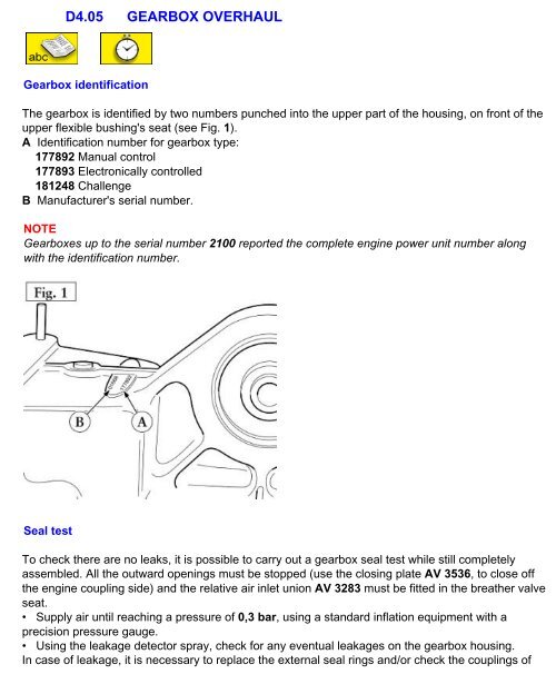
- Page 65 and 66: D4.01 REPLACING THE EXTERNAL COMPON
- Page 67 and 68: • Using a commercial bearing extr
- Page 69 and 70: • Remove the left-hand side catal
- Page 71 and 72: • Position the grommet with its c
- Page 73 and 74: Flexible upper bushing on the gearb
- Page 75 and 76: • Screw the nut (B) with the wash
- Page 77 and 78: • Fit the spacers on every side o
- Page 79 and 80: • Before fitting the new pad, che
- Page 81 and 82: Gearshift selection levers (Mechani
- Page 83 and 84: • Check that the equaliser (H) an
- Page 85 and 86: • Clean the coupling surfaces of
- Page 87 and 88: • Unscrew the three nuts and remo
- Page 89 and 90: • Pull the two cables from the pa
- Page 91 and 92: • Working from under the car, mak
- Page 93 and 94: 7 Check that the control lever is i
- Page 95 and 96: In case of interference during 4th
- Page 97 and 98: • Unscrew the four screws fasteni
- Page 99 and 100: IMPORTANT In case of replacement of
- Page 101 and 102: D4.04 DETACHING/RE-FITTING THE GEAR
- Page 103 and 104: Note for the US version On these ca
- Page 105 and 106: Support brackets for the pneumatic
- Page 107 and 108: • Unscrew and remove the screw wi
- Page 109 and 110: • Remove the movable frame from t
- Page 111: • Remove the movable frame from t
- Page 114 and 115: • Tighten screws (5), (7) and (8)
- Page 118 and 119: the covers and of the intermediate
- Page 121 and 122: 1 Gearbox housing 2 Intermediate pl
- Page 123 and 124: NOTES In the stages described below
- Page 125 and 126: • Beat out the flexible pins (D)
- Page 127 and 128: • Screw the extracting tool tie r
- Page 129 and 130: • Position the AV 3273 tool under
- Page 131 and 132: • Remove the race with bearing's
- Page 133 and 134: • Fit the shaft into the base of
- Page 135 and 136: To remove the double gears (31 and
- Page 137 and 138: Component maintenance and overhaul
- Page 139 and 140: • To remove the outer race (F) of
- Page 141 and 142: Intermediate plate Once the bearing
- Page 143 and 144: Synchronisers Synchronisation detai
- Page 145 and 146: Checking for wear The 1 st - 2 nd ,
- Page 147 and 148: grommet using gearbox oil. • Inse
- Page 149 and 150: The forks of the 1 st - 2 nd and 3
- Page 151 and 152: Lubrication of the crown and pinion
- Page 153 and 154: • Apply the locking product recom
- Page 155 and 156: positioning of the pinion in respec
- Page 157 and 158: Use tool AV 3255, composed of a bas
- Page 159 and 160: • Mount a new ring nut (30) and t
- Page 161 and 162: • Clean and degrease the surface
- Page 163 and 164: • Having mounted the flexible rin
- Page 165 and 166: ore meter. • Check that the shim
- Page 167 and 168:
Re-assembly of shaft-rod cluster wi
- Page 169 and 170:
Rear cover and plate re-assembly NO
- Page 171 and 172:
• Install the shoulder ring (50)
- Page 173 and 174:
7 Left-hand spacer for tapered roll
- Page 175 and 176:
• Using the tool AV 3275's punch
- Page 177 and 178:
• Lock the differential using the
- Page 179 and 180:
• Force open the roller cage (D)
- Page 181 and 182:
Calculating the spacer thickness Th
- Page 184 and 185:
and the size “V” of the left-ha
- Page 186 and 187:
The deviation “t” compared to t
- Page 188 and 189:
• Use the punch AV 3261 to refit
- Page 190 and 191:
• Install the tool AV 3266 in the
- Page 192 and 193:
If this is not the case, adjust the
- Page 194 and 195:
• Detach the brake calipers from
- Page 196 and 197:
• Remove the damaged casing and w
- Page 198 and 199:
D6.01 INTRODUCTION The "F1 Gearbox"
- Page 200 and 201:
suddenly and the automatic and prog
- Page 202 and 203:
The interfacing with the engine ECU
- Page 204 and 205:
The two levers, fitted behind the s
- Page 206 and 207:
the levers on the steering wheel an
- Page 208 and 209:
D6.05 HYDRAULIC SYSTEM The clutch a
- Page 210 and 211:
4 ON ON ON ON 5 ON ON ON 6 ON ON ON
- Page 212 and 213:
• Release the pipe bundle (D) fro
- Page 214 and 215:
• Check periodically the system's
- Page 216 and 217:
• Suitably position the Power Uni
- Page 218 and 219:
D6.07 ACTUATORS Tightening torques
- Page 220 and 221:
• Unfasten from the gearbox housi
- Page 222 and 223:
• Reconnect the rubber pipe, fast
- Page 224 and 225:
D6.08 MEASURING SENSORS AND SIGNAL
- Page 226 and 227:
The sensor's signals are transmitte
- Page 228 and 229:
Gearbox Input Shaft Revolution Sens
- Page 230 and 231:
To check the sensor, apply a ohmmet
- Page 232 and 233:
- pressure range: 0÷80 bar - respo
- Page 234 and 235:
Controls D6.09 SIGNALS AND CONTROLS
- Page 236 and 237:
Display The driver is informed abou
- Page 238 and 239:
D6.10 SYSTEM FUNCTIONS The function
- Page 240 and 241:
which are detected each time the sy
- Page 242 and 243:
D6.11 REPLACING THE THE ELECTRONIC
- Page 244 and 245:
NOTES To facilitate gear-shifting,
- Page 246 and 247:
D6.12 DIAGNOSIS Transmission Contro
- Page 248 and 249:
When everything is working properly
- Page 250 and 251:
• Reading the parameters on the F
- Page 252 and 253:
Control Unit (TCU) - Selflearning (
- Page 254 and 255:
• Measure the diameter of the lev
- Page 256 and 257:
• Now lock the screw (1) to the p