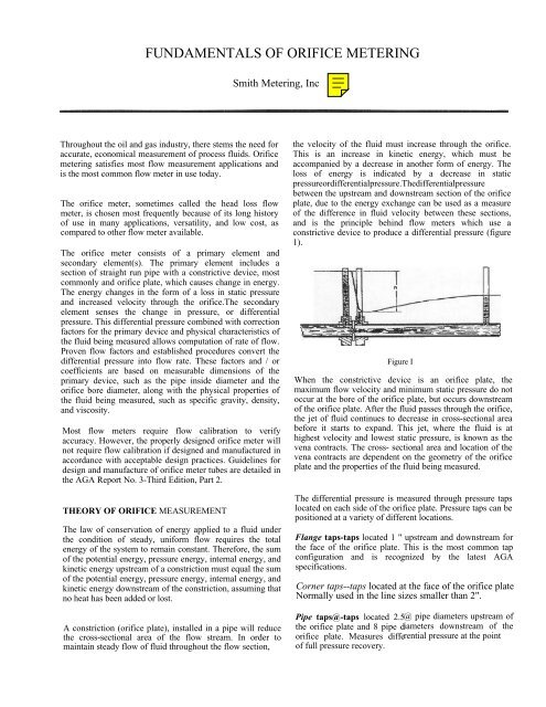
FUNDAMENTALS OF ORIFICE METERING
FUNDAMENTALS OF ORIFICE METERING
FUNDAMENTALS OF ORIFICE METERING

You also want an ePaper? Increase the reach of your titles
YUMPU automatically turns print PDFs into web optimized ePapers that Google loves.
<strong>FUNDAMENTALS</strong> <strong>OF</strong> <strong>ORIFICE</strong> <strong>METERING</strong><br />
Smith Metering, Inc<br />
Throughout the oil and gas industry, there stems the need for<br />
accurate, economical measurement of process fluids. Orifice<br />
metering satisfies most flow measurement applications and<br />
is the most common flow meter in use today.<br />
The orifice meter, sometimes called the head loss flow<br />
meter, is chosen most frequently because of its long history<br />
of use in many applications, versatility, and low cost, as<br />
compared to other flow meter available.<br />
The orifice meter consists of a primary element and<br />
secondary element(s). The primary element includes a<br />
section of straight run pipe with a constrictive device, most<br />
commonly and orifice plate, which causes change in energy.<br />
The energy changes in the form of a loss in static pressure<br />
and increased velocity through the orifice.The secondary<br />
element senses the change in pressure, or differential<br />
pressure. This differential pressure combined with correction<br />
factors for the primary device and physical characteristics of<br />
the fluid being measured allows computation of rate of flow.<br />
Proven flow factors and established procedures convert the<br />
differential pressure into flow rate. These factors and / or<br />
coefficients are based on measurable dimensions of the<br />
primary device, such as the pipe inside diameter and the<br />
orifice bore diameter, along with the physical properties of<br />
the fluid being measured, such as specific gravity, density,<br />
and viscosity.<br />
Most flow meters require flow calibration to verify<br />
accuracy. However, the properly designed orifice meter will<br />
not require flow calibration if designed and manufactured in<br />
accordance with acceptable design practices. Guidelines for<br />
design and manufacture of orifice meter tubes are detailed in<br />
the AGA Report No. 3-Third Edition, Part 2.<br />
THEORY <strong>OF</strong> <strong>ORIFICE</strong> MEASUREMENT<br />
The law of conservation of energy applied to a fluid under<br />
the condition of steady, uniform flow requires the total<br />
energy of the system to remain constant. Therefore, the sum<br />
of the potential energy, pressure energy, internal energy, and<br />
kinetic energy upstream of a constriction must equal the sum<br />
of the potential energy, pressure energy, internal energy, and<br />
kinetic energy downstream of the constriction, assuming that<br />
no heat has been added or lost.<br />
A constriction (orifice plate), installed in a pipe will reduce<br />
the cross-sectional area of the flow stream. In order to<br />
maintain steady flow of fluid throughout the flow section,<br />
the velocity of the fluid must increase through the orifice.<br />
This is an increase in kinetic energy, which must be<br />
accompanied by a decrease in another form of energy. The<br />
loss of energy is indicated by a decrease in static<br />
pressureordifferentialpressure.Thedifferentialpressure<br />
between the upstream and downstream section of the orifice<br />
plate, due to the energy exchange can be used as a measure<br />
of the difference in fluid velocity between these sections,<br />
and is the principle behind flow meters which use a<br />
constrictive device to produce a differential pressure (figure<br />
1).<br />
Figure I<br />
When the constrictive device is an orifice plate, the<br />
maximum flow velocity and minimum static pressure do not<br />
occur at the bore of the orifice plate, but occurs downstream<br />
of the orifice plate. After the fluid passes through the orifice,<br />
the jet of fluid continues to decrease in cross-sectional area<br />
before it starts to expand. This jet, where the fluid is at<br />
highest velocity and lowest static pressure, is known as the<br />
vena contracts. The cross- sectional area and location of the<br />
vena contracts are dependent on the geometry of the orifice<br />
plate and the properties of the fluid being measured.<br />
The differential pressure is measured through pressure taps<br />
located on each side of the orifice plate. Pressure taps can be<br />
positioned at a variety of different locations.<br />
Flange taps-taps located 1 " upstream and downstream for<br />
the face of the orifice plate. This is the most common tap<br />
configuration and is recognized by the latest AGA<br />
specifications.<br />
Corner taps--taps located at the face of the orifice plate<br />
Normally used in the line sizes smaller than 2".<br />
Pipe taps@-taps located 2.5@<br />
pipe diameters upstream of<br />
the orifice plate and 8 pipe diameters<br />
downstream of the<br />
orifice plate. Measures differential<br />
pressure at the point<br />
of full pressure recovery.
Vena Contracta taps@-taps located 1 pipe diameter<br />
upstream of the orifice plate and at the vena contracts<br />
on the downstream side of the orifice plate. Not<br />
recommended when a variety of orifice bore sizes are<br />
required to meet flow requirements.<br />
Radius tap&-taps located 1 pipe diameter upstream of the<br />
orifice plate and 1/2 pipe diameter downstream of the orifice<br />
plate.<br />
(See figure 2 for the different tap locations)<br />
Figure 2<br />
FLOW RATE COMPUTATION<br />
The fundamental flow equation is<br />
Oh= C' hw Pf<br />
where:<br />
Oh = Flow rate at base conditions C' =<br />
Orifice flow coeff icient<br />
hw = Differential pressure<br />
Pf = Absolute static pressure<br />
The orifice flow coefficient is calculated using other<br />
constants that identify diameter of the pipe, orifice bore<br />
diameter, base pressure and temperature with variables that<br />
relate to the physical properties of the fluid such as<br />
temperature, specific gravity, density, viscosity, and<br />
compressibility. Any change in the diameter of the orifice<br />
bore fluid composition or temperature will change the<br />
coefficient, thus, changing the rate of flow.<br />
Through the invention of flow computers and extensive<br />
research in orifice measurement, new flow equations have<br />
recently been developed that offer minimal uncertainty in<br />
total flow computations. The new equations, in accordance<br />
with the Third Edition of AGA Report No. 3- Part 1, are<br />
extensive and are not addressed in this paper. Details of the<br />
new equations are available in advanced orifice metering<br />
publications.<br />
PRIMARY <strong>ORIFICE</strong> <strong>METERING</strong> EQUIPMENT<br />
Implementation of highly accurate secondary metering<br />
equipment (flow computers), the need for close<br />
tolerance primary equipment (meter tubes and orifice<br />
plates) is<br />
critical. AGA Report No. 3-Part 2 (API 14.3) provides<br />
recommended design considerations of orifice meter tubes.<br />
The following-is an overview of primary orifice metering<br />
equipment.<br />
Orifice Flange Unions<br />
The original orifice plate holding device was the orifice<br />
flange union (Figure 3). The orifice flange union was the<br />
only type orifice holder available until the invention of the<br />
orifice fifting, some 50+ years ago. Though inexpensive as<br />
compared to other devices, the orifice flange union utilizes<br />
the more expensive paddle plate and requires additional<br />
labor to perform an orifice plate change. The operator must<br />
loosen all bolts and remove half of the bolts, spread the<br />
flanges by use of jackscrews and remove the plate. Gaskets<br />
must be replaced in most cases.<br />
The orifice flange union is still used where periodical<br />
inspection is not required and the overall accuracy is usually<br />
less critical.<br />
<strong>ORIFICE</strong> FITTINGS<br />
Figure 3<br />
Frequent inspection of the orifice plate is often<br />
necessary to be certain the orifice plate is of quality<br />
condition to insure accuracy. In some installations,<br />
flow will vary to the extent that various sizes of<br />
orifices are required to keep the differential within<br />
range of ,the secondary device.<br />
Orifice fittings are designed to reduce the time and<br />
cost of inspection or changing of the orifice plate.<br />
Orifice fittings also offer precision machined critical<br />
dimensions and provide accurate centering of the bore<br />
in the center of the meter tube.<br />
For the purpose of inspection and calibration, the<br />
orifice fifting should include a flange connection,<br />
preferably on the downstream side. The use of<br />
weldneck orifice fittings is generally not recommended<br />
for minimum uncertainty since weldneck fittings in<br />
small sizes do not allow accessibility for<br />
measurements to be taken near the orifice plate.
Single Chamber Orifice Fittings<br />
The single chamber orifice fitting, such as the PECO<br />
Orificemaster (figure 4) is for use where the flow to<br />
the meter tube can be shut down, or bypassed and the<br />
line depressurized without costly interruption to the<br />
pipeline or process. Orifice fiftings of this type do not<br />
require the removal of flange bolts or spreading of<br />
flanges to remove the orifice plate. These type fiftings<br />
also avoid the loss of liquid from the pipeline, which<br />
occurs when flanges are separated. To remove the<br />
orifice plate from the single chamber fitting the<br />
operator must loosen the cover set screws, remove the<br />
clamping bar and lift the cover plate/ orifice plate from<br />
the fitting. The orifice plate can then be inspected for<br />
quality and placed back into the fitting by reversing the<br />
above procedure.<br />
Figure 4<br />
Double Chamber Orifice Fitting<br />
Double chamber orifice fittings, such as the PECO<br />
Measuremaster (figure 5) orifice fifting, are for use where it<br />
is necessary or desirable to be able to remove the orifice<br />
plate form the meter tube without interrupting the flow in the<br />
pipeline.These fittings have a lower chamber in which the<br />
plate carrier accurately centers the orifice in the meter tube<br />
and between the high- and low- pressure taps. A cylindrical<br />
plug valve is located between the lower chamber and upper<br />
chamber. When closed, isolates the upper chamber from the<br />
pipeline pressure when the orifice plate and carrier assembly<br />
has been withdrawn from the lower chamber into the upper<br />
chamber. The pressure in the upper chamber is evacuated by<br />
means of a bleed-valve. Then the clamp and cover plate are<br />
removed. The Measuremaster orifice fifting retracts the plate<br />
carrier from the lower chamber into the upper chamber by<br />
means of a non-rising elevator screw.<br />
After removing the cover plate, further turning of the<br />
elevator screw will cause projection on the top of the carrier<br />
to lever the carrier out of the fifting where the orifice plate<br />
can be easily inspected or changed. The orifice plate is<br />
returned to the flow bore by reversing this procedure.<br />
Fittings of ANSI Class 600 and higher and larger fittings of<br />
lower classes have equalizer valves which are used to<br />
equalize the pressure in the top chamber with that of the<br />
pipeline so the pressure isolating valve between the two<br />
chambers can be opened easily before the carrier assembly is<br />
lowered and centered in the meter tube.<br />
Figure 5<br />
Orifice fifting standards, tolerances, and tests have been<br />
established to allow for uncertainty limits comparable to the<br />
original test equipment used for the API test data.<br />
METERTUBES<br />
Meter tubes (figure 6) designed, fabricated, and<br />
inspected in strict accordance with AGA 3 and the<br />
procedures and techniques shown in Parts 1 and 3, will<br />
provide minimum uncertainty in orifice metering. The<br />
following guidelines, along with proper metering<br />
practices, should be strictly adhered to.<br />
Pipe Selection<br />
Figure 6<br />
The selection of pipe or tubing for meter tube fabrication is<br />
of utmost importance. Surface roughness has increased<br />
effect on uncertainty, especially in larger diameter ratios,<br />
above .6 beta. A visual inspection is required to avoid pipe<br />
with irregularities such as grooves, ridges from seams,<br />
distortions and pits. The surface finish can be improved by<br />
machining, coating, or grinding.<br />
The maximum surface finish of a meter tube is 300<br />
microinches for diameter ratios (beta) less than .60.<br />
However, for meter tubes with diameter ratios greater<br />
than or equal to .60, the tolerance for surface<br />
roughness is reduced to 250 microinches.<br />
Most metertubes are designed using.75 beta ratio design<br />
criteria in order to utilize the full capacity of the meter
tube. Therefore, most consider 250 microinches surface<br />
roughness to be the maximum roughness for a quality meter<br />
tube.<br />
Meter Tube Lengths<br />
The flow of fluid through elbows, tees, and valves will cause<br />
turbulence, which adversely effects the fluid measurement.<br />
For accurate flow measurement, the fluid should enter the<br />
orifice plate free from swirls and cross currents.<br />
In order to achieve the desired flow profile, adequate<br />
upstream and downstream straight pipe is required and<br />
/ or flow conditioners such as straightening vanes.<br />
The use of flow conditioners (straightening vanes) will also<br />
reduce turbulence within the meter tube while allowing<br />
shorter lengths of straight pipe.<br />
Research continues on straightening vanes in regard to effect<br />
location and relationship to meter tube lengths.<br />
AGA 3 includes five commonly used piping<br />
configurations and has defined minimum lengths 'of<br />
straight pipe preceding and following the orifice plate<br />
as shown in the example in figure 7.<br />
Figure 7<br />
There are to be no pipe connections within the minimum<br />
amount of straight pipe with the exception of the pressure<br />
taps, temperature probes, and/or straightening vane<br />
attachments<br />
The meter tube lengths recommended by the third edition of<br />
AGA 3 have not changed from the second edition. There is<br />
considerable research being conducted regarding minimum<br />
lengths of meter tube pipe required.<br />
MeterTube Inspection and Calibration<br />
Upon completion of fabrication, the meter tube shall be<br />
checked for compliance with standards and document the<br />
calibration results.<br />
It should be noted that the third edition does not require<br />
maintaining diameter measurements within published pipe<br />
diameters as per previous editions of AGA 3. The practice<br />
of using published diameters and coefficients resulted in<br />
inherent flow computation error since it is unlikely that<br />
meter tubes are manufactured exactly the same diameter as<br />
the published pipe diameter.<br />
The intent of the third edition AGA 3 is to enhance the<br />
accuracy of the meter tube by using actual, measured<br />
diameters.Thus, eliminating flow computation errors due to<br />
inaccurate diameter ratios.<br />
DIAMETER MEASUREMENTS &TOLERANCES<br />
Meter Tube Diameter<br />
The measured diameter of the meter tube shall be<br />
determined by taking a minimum of four equally spaced<br />
diameter measurements made in a plane one (1) inch from<br />
the upstream face of the orifice plate. The average of these<br />
four or more measurements is defined as the measured meter<br />
tube diameter. Check measurements should be made at two<br />
or more additional cross sections. These check<br />
measurements should be taken at points that indicate the<br />
maximum and minimum diameters. One measurement<br />
should be taken at least two (2) pipe diameters upstream of<br />
the orifice plate or past the plate holder or weld, whichever<br />
is greater. Individual check measurements shall be made on<br />
the downstream section of the meter tube in a plane one (1)<br />
inch from the down- stream face of the orifice plate.<br />
Additional measurements shall be taken on at least two other<br />
cross-sections in the downstream section of the meter tube.<br />
The check measurements are to verify uniformity but do not<br />
become part of the mean meter tube diameter. The absolute<br />
value of the percentage differences between the measured<br />
meter tube internal diameter and any individual diameter<br />
measurement within a distance of one meter tube diameter<br />
on the upstream side of the orifice plate shall not exceed<br />
0.25 percent of measured diameter (Dm)(See figure 8).
~<br />
FIARST F9FME -o-Z- C.!2AS-m. C=W ^Ae-,fts-4<br />
- I L.#FMT@@ FMF@,s K3.959& -XA;@:VTMjr->I..06"WMM<br />
The percentage difference between the maximum measured<br />
individual internal diameter measurement and the minimum<br />
measured individual internal diameter measurement of<br />
upstream meter tube individual internal measurements,<br />
including those within the first meter tube diameter upstream<br />
of the orifice plate shall not exceed 0.5 percent of measured<br />
diameter (Dm) (figure 5).<br />
The absolute value of the percentage difference<br />
between the measured meter tube diameter (Dm) and<br />
any individual internal diameter on the downstream<br />
side shall not exceed 0.5 percent of measured diameter<br />
(Dm) (figure 5).<br />
The measured internal diameter in the inside diameter<br />
of the upstream section of the meter tube measured at<br />
the temperature of the meter tube (Tm) at the time of<br />
diameter measurements.<br />
All diameter measurements (Dm) are measurements at the<br />
temperature, at the time when the measurements are taken.<br />
The (Dm) measurements are used to calculate the<br />
meter tube diameter (Dr) at reference temperature<br />
assumed to be 68 degrees F. These measurements<br />
make up the certified or calibrated meter tube diameter.<br />
The calculated diameter (D) is the diameter used in the flow<br />
computations at actual flowing temperature, which corrects<br />
the diameter of the meter tube for thermal expansion.<br />
<strong>ORIFICE</strong> PLATES<br />
The orifice plate is the heart of the primary device. The<br />
orifice plate is a relatively inexpensive component of the<br />
orifice meter tube. Orifice plates are manufactured to<br />
stringent guidelines and tolerances for flatness, bore<br />
diameter, surface finish, and imperfections in machining<br />
such as nicks and wire edges on the bore. Specific tolerances<br />
applicable to orifice plates are explained in<br />
hAu-- a -IRUIMM. -/- 13."-AIL
SEGMENTAL<br />
BORE<br />
Figure 9<br />
Quadrant Radius Orifice Plates<br />
Quadrant radius orifices are recommended for<br />
measurement of viscous fluids which have pipe<br />
Reynonds Numbers below 1 0,000. An increase in the<br />
viscosity of a fluid flowing through a sharp edge<br />
orifice will increase the diameter of the vena contracts,<br />
which results in a decrease in differential pressure.<br />
However, an increase in the viscosity of a fluid<br />
flowing through a flow nozzle increases the friction<br />
drop in the flow through the nozzle, which results in an<br />
increase in the differential.<br />
The quadrant radius orifice plate combines these two effects<br />
to produce a constant coefficient.<br />
SECONDARY EQUIPMENT<br />
The secondary equipment consists of a bellows type<br />
recorder (figure 1 0) or flow computer (figure 1 1).<br />
The recorder senses the static pressure, differential<br />
pressure<br />
Figure 10<br />
0<br />
QUADRANT RADIUS<br />
BORE<br />
and temperature and records the information on a circular<br />
chart. The chart is removed and taken to a remote location to<br />
be integrated. This determines the average of the charted<br />
variables over the time period indicated on the chart. The<br />
results, along with the physical characteristics of the fluid,<br />
are used to calculate the total flow rate over the charted<br />
period. This method of recording and integration has been<br />
the dominant method of determining flow rates for many<br />
years.<br />
Electronic flow measurement (EFM) is rapidly<br />
becoming the preferred method of data accumulation<br />
and volume calculation. The electronic flow computer<br />
is often used in conjunction with the flow recorder as<br />
shown above. The advantage in using flow computers<br />
is that they provide precise, real time measurements<br />
and / or computations. The flow computer senses the<br />
variables (pressure, differential, and temperature) and<br />
utilizes transducers to convert these variables to<br />
electronic data. The computer then performs the<br />
appropriate flow computations as stores the data until<br />
it is retrieved.<br />
EFM measurement is generally considered to provide<br />
more accurate and efficient flow computations.<br />
SUMMARY<br />
Figure I 1<br />
The wide variety of applications available today demands<br />
dependable, accurate measurement. Recently, significant<br />
improvements in metering standards and secondary<br />
equipment have enhanced the overall quality and efficiency<br />
of orifice metering. Given the proper design considerations,<br />
orifice metering satisfies the measurement requirements for<br />
a variety of applications.