Sun Glint Flag Algorithm
Sun Glint Flag Algorithm
Sun Glint Flag Algorithm

Create successful ePaper yourself
Turn your PDF publications into a flip-book with our unique Google optimized e-Paper software.
MERIS<br />
ESL<br />
Doc:<br />
Name:<br />
Issue:<br />
Date:<br />
Page:<br />
PO-TN-MEL-GS-0005<br />
<strong>Sun</strong>glint <strong>Flag</strong> <strong>Algorithm</strong><br />
4 Rev.: 2<br />
10 June 2003<br />
13-1<br />
ATBD 2.13 — SUN GLINT FLAG ALGORITHM<br />
Issue 4, revision 2<br />
10 June 2003<br />
F. Montagner<br />
V. Billat<br />
S. Bélanger<br />
ACRI
MERIS<br />
ESL<br />
Doc:<br />
Name:<br />
Issue:<br />
Date:<br />
Page:<br />
PO-TN-MEL-GS-0005<br />
<strong>Sun</strong>glint <strong>Flag</strong> <strong>Algorithm</strong><br />
4 Rev.: 2<br />
10 June 2003<br />
13-2<br />
1. INTRODUCTION.............................................................................................................. 3<br />
2. ALGORITHM OVERVIEW ............................................................................................ 3<br />
3. ALGORITHM DESCRIPTION ....................................................................................... 3<br />
3.1. Theoretical description...........................................................................................................................3<br />
3.1.1. Physics of the problem ..................................................................................................................... 3<br />
3.1.2. Mathematical description of the <strong>Algorithm</strong>...................................................................................... 6<br />
3.1.3. Parameter description....................................................................................................................... 9<br />
3.1.4. Error budget estimates...................................................................................................................... 9<br />
3.2. Practical considerations........................................................................................................................10<br />
3.2.1. Calibration and Validation ............................................................................................................. 10<br />
3.2.2. Quality control and diagnostics...................................................................................................... 10<br />
3.2.3. Exception handling......................................................................................................................... 10<br />
3.2.4. Output Product ............................................................................................................................... 10<br />
4. ASSUMPTIONS AND LIMITATIONS......................................................................... 10<br />
4.1. Assumptions ..........................................................................................................................................10<br />
4.2. Limitations.............................................................................................................................................10
1. Introduction<br />
MERIS<br />
ESL<br />
Doc:<br />
Name:<br />
Issue:<br />
Date:<br />
Page:<br />
PO-TN-MEL-GS-0005<br />
<strong>Sun</strong>glint <strong>Flag</strong> <strong>Algorithm</strong><br />
4 Rev.: 2<br />
10 June 2003<br />
13-3<br />
This chapter describes the algorithm used to perform a correction for ocean pixels which are<br />
contaminated by <strong>Sun</strong> glint : specular reflection of <strong>Sun</strong> light over ocean waves. Corrected<br />
reflectances are input to the atmosphere corrections algorithm (ATBD 2.7), and is made<br />
available in the MERIS Level 2 Product.<br />
2. <strong>Algorithm</strong> Overview<br />
The glint reflectance estimate algorithm is performed on every ocean pixel in the MERIS<br />
data. It uses external knowledge of the wind speed and direction, and the illumination and<br />
observation geometry of each pixel, to estimate the level of <strong>Sun</strong> glint contribution to the<br />
surface reflectance. When that contribution is below a "low threshold" value it is neglected.<br />
When above that threshold and below a "high threshold" it is substracted from the signal;<br />
when above the "high threshold" pixels are flagged and not processed further. The <strong>Sun</strong> glint<br />
flag is raised when that contribution exceeds a threshold value (to be determined).<br />
3. <strong>Algorithm</strong> Description<br />
3.1. Theoretical description<br />
3.1.1. Physics of the problem<br />
The estimate of the <strong>Sun</strong> glint contribution to the ocean signal is based on the Cox and Munk<br />
model. These authors have proposed a model that considers the sea surface as a collection of<br />
facets, each with individual slope components zx and zy. The probability distribution of facet<br />
slopes p(zx, zy) depends on the wind speed and direction.<br />
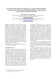
In a target-fixed, local coordinates system with the y axis aligned with the <strong>Sun</strong> azimuth, given<br />
the <strong>Sun</strong> zenith angle θs and the sensor zenith angle θv and azimuth angle φv specifying the<br />
reflected ray, a wave facet specified by the zenith angle β and azimuth angle α (taken<br />
clockwise from the <strong>Sun</strong>) of its outward normal (see figure 3.1.1-1 below), the condition for<br />
that facet to reflect <strong>Sun</strong> light in the direction (θv,φv) towards the sensor is :<br />
cos2ω = cos( θ )cos( θs) + sin( θ )sin( θ )cos( ∆φ )<br />
(1)<br />
v v s<br />
where ω is the specular reflection angle and ∆φ is defined as φs - φv.
MERIS<br />
ESL<br />
Doc:<br />
Name:<br />
Issue:<br />
Date:<br />
Page:<br />
PO-TN-MEL-GS-0005<br />
<strong>Sun</strong>glint <strong>Flag</strong> <strong>Algorithm</strong><br />
4 Rev.: 2<br />
10 June 2003<br />
13-4<br />
According to the law of reflection, the vector difference between the reflected and incident<br />
rays must lie along the facet normal. From this, it is possible to express the facet angles α and<br />
β as a function of the incident and reflected directions.<br />
The angle β formed by the facet normal and the z-axis is computed as :<br />
cosθv + cosθ<br />
cosβ<br />
=<br />
( 2 + 2cos2 ω)<br />
s<br />
1<br />
(2)<br />
2<br />
The azimuth of the facet α measured clockwise from the sun (y-axis) is :<br />
cosα<br />
=<br />
− sinθ sin ∆φ<br />
v<br />
( 2 + 2 2 )<br />
sinβ cos ω<br />
1<br />
2<br />
(sinθvcos∆φ + sin θs)<br />
sinα<br />
=<br />
sin β( 2 + 2cos 2ω)<br />
1<br />
2<br />
The slopes of the wave facet in the x and y-directions zx, zy can be expressed as a function of<br />
the facet azimuth α and zenith β as follows :<br />
zx = sinα tanβ<br />
(5)<br />
zy = cosα tanβ<br />
(6)<br />
which leads to :<br />
z<br />
z<br />
x<br />
y<br />
−sinθ<br />
v sin ∆ φ<br />
=<br />
(7)<br />
cosθ + cosθ<br />
s v<br />
sinθ vcos<br />
∆ φ + sinθs<br />
=<br />
cosθ + cosθ<br />
s v<br />
Let W be the wind speed modulus. It is expressed as :<br />
W(j,f) = (W_u(j,f) 2 +W_v(j,f) 2 ) 1/2 (9)<br />
Let χ be the wind direction in the local frame (χ taken clockwise from the sun). If the sun<br />
system (x,y) is rotated through an angle χ to a new system (x',y') related to the wind direction,<br />
then the Cox and Munk model provides facet slopes z'x and z'y in this wind system as:<br />
z x<br />
' = sinα 'tanβ<br />
(10)<br />
z y<br />
' = cosα 'tanβ<br />
(11)<br />
(3)<br />
(4)<br />
(8)
where α' = α - χ<br />
Therefore :<br />
zx' = cos(χ) zx + sin(χ) zy<br />
zy' = - sin(χ) zx + cos(χ) zy<br />
and with ξ =<br />
σ<br />
1<br />
c<br />
z' x and η<br />
σu<br />
= 1<br />
incident radiation in the sensor direction is :<br />
MERIS<br />
ESL<br />
Doc:<br />
Name:<br />
Issue:<br />
Date:<br />
Page:<br />
PO-TN-MEL-GS-0005<br />
<strong>Sun</strong>glint <strong>Flag</strong> <strong>Algorithm</strong><br />
4 Rev.: 2<br />
10 June 2003<br />
13-5<br />
(12)<br />
(13)<br />
z' y ,the probability that the facet reflects specularly the<br />
⎡<br />
2<br />
3<br />
2 2 1−( 1/ 2) C ( − ) −( / ) C ( − ) + ⎤<br />
+<br />
21 ξ 1 1 6 03 η 3η<br />
ξ η<br />
1 − ⎢<br />
⎥<br />
pz (' x,' z y)<br />
= e 2<br />
4 2<br />
2 2<br />
. ⎢(<br />
1/ 24) C40( ξ − 6ξ + 3) + ( 1/ 4) C22<br />
( ξ −1)( η − 1)<br />
+ ⎥<br />
2πσ<br />
uσc ⎢<br />
4 2<br />
⎥<br />
⎣⎢<br />
( 1/ 24) C04<br />
( η − 6η + 3)<br />
⎦⎥<br />
where :<br />
σc(j,f) = (σc 0 + σc 1 W) 1/2 with σc 0 = 0,003 and σc 1 = 1,92.10 -3 (15)<br />
σu(j,f) = (σu 0 + σu 1 W) 1/2 with σu 0 = 0,000 and σu 1 = 3,16.10 -3 (16)<br />
C21 = C21 0 + C21 1 W with C21 0 = 0,01 and C21 1 = - 0,0086 (17)<br />
C22 = 0,12 (18)<br />
C03 = C03 0 + C03 1 W with C03 0 = 0,04 and C03 1 = - 0,033 (19)<br />
C40 = 0,40 (20)<br />
C04 = 0,23 (21)<br />
The <strong>Sun</strong> glint reflectance is then :<br />
π r(<br />
ω)<br />
ρg( θv, θs,<br />
∆φ ) = pz ( ′ x, z′<br />
y)<br />
4cosθ<br />
cosθ cos β<br />
s v<br />
4 (22)<br />
where the Fresnel reflection coefficient r(ω) can be considered as a constant (0,02) for<br />
incidence between 0 and 50 degrees.<br />
(14)
- χ<br />
MERIS<br />
ESL<br />
s<br />
α - π<br />
Figure 3.1.1-1 : <strong>Sun</strong> glint geometry<br />
3.1.2. Mathematical description of the <strong>Algorithm</strong><br />
Doc:<br />
Name:<br />
Issue:<br />
Date:<br />
Page:<br />
v<br />
−∆φ−π<br />
PO-TN-MEL-GS-0005<br />
<strong>Sun</strong>glint <strong>Flag</strong> <strong>Algorithm</strong><br />
4 Rev.: 2<br />
10 June 2003<br />
13-6<br />
The <strong>Sun</strong> glint reflectance observed by MERIS is estimated at each ocean pixel taking as<br />
inputs :<br />
1. the <strong>Sun</strong> zenith and azimuth angles, observer zenith and azimuth angles at the pixel,<br />
interpolated from the level 1 product annotation at the nearest tie points;<br />
2. the wind at 10m vector in the local frame, taken at the nearest tie point.<br />
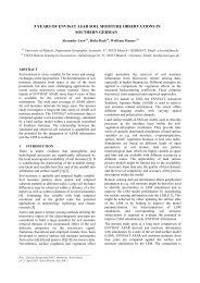
The local reference frame FL is defined at the pixel, with the x axis pointing Eastward, the y<br />
axis pointing Northward and the z-axis aligned with the outward local normal (see figure<br />
3.1.2-1).
MERIS<br />
ESL<br />
Figure 3.1.2-1 : Local reference frame<br />
Doc:<br />
Name:<br />
Issue:<br />
Date:<br />
Page:<br />
PO-TN-MEL-GS-0005<br />
<strong>Sun</strong>glint <strong>Flag</strong> <strong>Algorithm</strong><br />
4 Rev.: 2<br />
10 June 2003<br />
13-7<br />
The <strong>Sun</strong> glint reflectance is estimated following the development in 3.1.1 above. It is then<br />
converted to TOA reflectance ρ * g using an estimate of atmospheric transmittance :<br />
t = exp(-(τR(b,j,f) + τoz(b,j,f))/cos(θs(j,f))) exp(-(τR(b,j,f) + τoz(b,,j,f))/cos(θv(j,f)))<br />
ρ * g = t ρg<br />
if ρ * g in [GLINT_THR_LOW... GLINT_THR_HIGH]<br />
then ρ'T = ρT - ρ * g + GLINT_THR_LOW and Me<strong>Glint</strong> = TRUE<br />
if ρ * g > GLINT_THR_HIGH<br />
then Uncglint = FALSE.<br />
Values for GLINT_THR_LOW and GLINT_THR_HIGH are determined following tests of<br />
the Atmospheric Correction above water (see ATBD 2.7) in presence of increasing amount of<br />
glint. GLINT_THR_LOW is fixed at the lowest level where glint influences the results of the<br />
atmosphere correction. GLINT_THR_HIGH depends on the value of the TOA reflectance at<br />
865nm (the band most sensitive to glint in the atmospheric correction): glint correction is<br />
disabled when ρ * g exceeds a specified fraction (0.8) of the observed reflectance. In such case,<br />
all level 2 products except water vapour should be flagged.
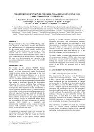
Wind u and v<br />
components<br />
Cartesian-><br />
polar<br />
Wind speed<br />
modulus<br />
First-order<br />
polynomials<br />
σc,σu,cij<br />
coeff.<br />
do not correct<br />
do not flag<br />
flag "Uncglint"<br />
do not correct<br />
ϕw<br />
GLINT_THR_<br />
LOW<br />
No<br />
MERIS<br />
ESL<br />
Difference<br />
No<br />
ϕs<br />
χ<br />
ρ*g><br />
GLINT_THR_LOW<br />
Yes<br />
ρ*g><br />
GLINT_THR_HIGH<br />
Correct and flag<br />
flag towards atmosphere<br />
Yes<br />
θs,θv,β<br />
Figure 3.1.2-2 : <strong>Algorithm</strong> flow chart<br />
Doc:<br />
Name:<br />
Issue:<br />
Date:<br />
Page:<br />
θs θv ϕv<br />
Reflection<br />
condition<br />
α,β<br />
Probability<br />
density estimate<br />
p(z'x,z'y)<br />
Reflectance<br />
estimate<br />
ρ∗g<br />
flag "Me<strong>Glint</strong>"<br />
PO-TN-MEL-GS-0005<br />
<strong>Sun</strong>glint <strong>Flag</strong> <strong>Algorithm</strong><br />
4 Rev.: 2<br />
10 June 2003<br />
13-8<br />
ω
3.1.3. Parameter description<br />
MERIS<br />
ESL<br />
Doc:<br />
Name:<br />
Issue:<br />
Date:<br />
Page:<br />
PO-TN-MEL-GS-0005<br />
<strong>Sun</strong>glint <strong>Flag</strong> <strong>Algorithm</strong><br />
4 Rev.: 2<br />
10 June 2003<br />
13-9<br />
Symbol Descriptive name I/O Origin<br />
θs[j,f] <strong>Sun</strong> zenith angle for pixel j,f i interpolated from Level 1b product<br />
tie points<br />
φs[j,f] <strong>Sun</strong> azimuth for pixel j,f i interpolated from Level 1b product<br />
θv[j,f] Observer zenith angle for pixel<br />
j,f<br />
tie points<br />
i interpolated from Level 1b product<br />
tie points<br />
φv[j,f] Sensor azimuth for pixel j,f i interpolated from Level 1b product<br />
tie points<br />
W_u, W_v Wind vector components i interpolated from Level 1b product<br />
tie points<br />
σc 0 , σc 1 Polynomial coefficients for σc i σc 0 = 0.003<br />
σc 1 = 0.00192<br />
σu 0 , σu 1 Polynomial coeff.icients for σu i σu 0 = 0.000<br />
σu 1 = 0.00316<br />
C21 0 , C21 1 Polynomial coefficients for C21 i C21 0 = 0.01<br />
C21 1 = - 0.0086<br />
C03 0 , C03 1 Polynomial coefficients for C03 i C03 0 = 0.04<br />
C03 1 = - 0.033<br />
C40, C22, C04 Weighting factors in p(z'x,z'y) i C40=0.4<br />
C22= 0.12<br />
C04= 0.23<br />
r(ω) Fresnel reflection factor i 0.022<br />
GLINT_THR_LOW Threshold for low glint i TBD<br />
GLINT_THR_HIGH Threshold for high glint i TBD<br />
ρg Reflectance estimate at surface c<br />
ρ ∗ g Reflectance estimate at TOA c<br />
t Atmospheric transmittance c<br />
MEGLINT_F(j,f) <strong>Flag</strong> for medium glint o<br />
UNCGLINT_F(j,f) <strong>Flag</strong> for uncorrected glint o<br />
3.1.4. Error budget estimates<br />
Because of<br />
• the uncertainty on wind from ECMWF global models (typically 2 m.s -1 on wind speed);<br />
• the error bars of the Cox and Munk model,<br />
there is an uncertainty in the determination of ρg. The value of GLINT_THR_LOW should be<br />
established taking that uncertainty into account so as to avoid "over correcting".<br />
The value of GLINT_THR_HIGH will be established taking the saturation of the aerosol<br />
correction dedicated channels (705, 775, 865 nm) into account : It is not worth correcting<br />
these pixels for glint.
3.2. Practical considerations<br />
MERIS<br />
ESL<br />
3.2.1. Calibration and Validation<br />
Doc:<br />
Name:<br />
Issue:<br />
Date:<br />
Page:<br />
PO-TN-MEL-GS-0005<br />
<strong>Sun</strong>glint <strong>Flag</strong> <strong>Algorithm</strong><br />
4 Rev.: 2<br />
10 June 2003<br />
13-10<br />
The value of GLINT_THR should be established using :<br />
1. simulation results, establishing the <strong>Sun</strong> glint sensitivity threshold of the atmosphere<br />
correction algorithm;<br />
2. airborne images of reflectance (a high spectral resolution is not necessary).<br />
The glint reflectance estimate may be implemented in Look-Up Tables.<br />
3.2.2. Quality control and diagnostics<br />
The PCD in the level 1 product header, indicating the quality of the available wind data,<br />
should be repeated in the level 2 product header to notify the likely error in the size of the <strong>Sun</strong><br />
glint patch.<br />
N/A<br />
3.2.3. Exception handling<br />
3.2.4. Output Product<br />
The output of the algorithm is a boolean flag for each pixel of the frame : <strong>Glint</strong>_f[j,f]. When<br />
true, that flag indicate that the pixel is (most likely) meaningfully affected by <strong>Sun</strong> glint and<br />
should not be processed further. Another flag indicates when the correction has been applied.<br />
4. Assumptions and Limitations<br />
4.1. Assumptions<br />
No further assumptions than mentioned in 3.1 above.<br />
4.2. Limitations<br />
This algorithm accepts as an established reference the Cox and Munk model. That model does<br />
not provide a complete description of the wave slope distribution :<br />
1. swell, not related to local wind, is not taken into account;<br />
2. the model is valid for a deep ocean where interaction with the sea bottom is negligible. In<br />
reality, the wave profile is distorted when the sea bottom gets close to the surface.
MERIS<br />
ESL<br />
Doc:<br />
Name:<br />
Issue:<br />
Date:<br />
Page:<br />
ATBD 2.13 — MERIS DATA PRODUCT SUMMARY SHEET<br />
PO-TN-MEL-GS-0005<br />
<strong>Sun</strong>glint <strong>Flag</strong> <strong>Algorithm</strong><br />
4 Rev.: 2<br />
10 June 2003<br />
13-11<br />
Product Name: <strong>Sun</strong> <strong>Glint</strong> <strong>Flag</strong> <strong>Algorithm</strong><br />
Product Code: SUNGLINT<br />
Product Level: 2<br />
Description of the product: The product is a flag indicating the occurrence of sun glint<br />
contamination<br />
Product Parameters:<br />
Coverage: global<br />
Packaging:<br />
Units: no<br />
Range:<br />
Sampling: pixel by pixel<br />
Resolution: radiometric: N/A<br />
spatial: full<br />
Accuracy:<br />
Geo-location Requirements: yes<br />
Format: 2 bits / sample<br />
Appended Data:<br />
Frequency of generation: 1 product per orbit<br />
Size of the Product:<br />
Additional Information:<br />
Identification of bands used in algorithm: 865nm<br />
Assumptions on MERIS input data: none<br />
Identification of ancillary an auxiliary data: Wind vector, illumination and viewing zenith<br />
and azimuth angles<br />
Assumptions on ancillary and auxiliary data: available at input Level 1B product tie points<br />
Input from other ENVISAT instruments: none