ProStream 1000 - Harmonic Inc
ProStream 1000 - Harmonic Inc
ProStream 1000 - Harmonic Inc

You also want an ePaper? Increase the reach of your titles
YUMPU automatically turns print PDFs into web optimized ePapers that Google loves.
<strong>ProStream</strong> TM <strong>1000</strong><br />
Stream Processing Platform<br />
Software User Guide<br />
<strong>ProStream</strong> <strong>1000</strong> VERSION 6.2<br />
Rev A
Disclaimer<br />
<strong>Harmonic</strong> reserves the right to alter the equipment specifications and descriptions in this publication without prior notice. No part of<br />
this publication shall be deemed to be part of any contract or warranty unless specifically incorporated by reference into such<br />
contract or warranty. The information contained herein is merely descriptive in nature, and does not constitute a binding offer for<br />
sale of the product described herein. <strong>Harmonic</strong> assumes no responsibility or liability arising from the use of the products described<br />
herein, except as expressly agreed to in writing by <strong>Harmonic</strong>. The use and purchase of this product do not convey a license under<br />
any patent rights, copyrights, trademark rights, or any intellectual property rights of <strong>Harmonic</strong>. Nothing hereunder constitutes a<br />
representation or warranty that using any products in the manner described herein will not infringe any patents of third parties.<br />
Trademark Acknowledgments<br />
<strong>Harmonic</strong> and all <strong>Harmonic</strong> product names are trademarks of <strong>Harmonic</strong> <strong>Inc</strong>. All other trademarks are the property of their respective<br />
owners.<br />
Conventions<br />
NOTE: The Note symbol calls your attention to additional information that you will benefit from<br />
heeding. It may be used to call attention to an especially important piece of information you need, or it<br />
may provide additional information that applies in only some carefully delineated circumstances.<br />
TIP: The Tip symbol calls your attention to parenthetical information that is not necessary for performing<br />
a given procedure, but which, if followed, might make the procedure or its subsequent steps easier,<br />
smoother, or more efficient.<br />
In addition to these symbols, this manual uses the following text conventions:<br />
Data Entry: indicates text you enter at the keyboard.<br />
User Interface: indicates a button to click, a menu item to select, or a key or key sequence<br />
to press.<br />
Screen Output: shows console output or other text that is displayed to you on a<br />
computer screen.<br />
Bold: indicates the definition of a new term.<br />
Italics: used for emphasis, cross-references, and hyperlinked cross-references in online<br />
documents.<br />
Related Documentation<br />
Splicing Application Note<br />
Slate Application Note<br />
Edge Descramble Unit Software User Guide<br />
Transcoding Application Note<br />
© 2012 <strong>Harmonic</strong> <strong>Inc</strong>. All rights reserved.
Table of Contents<br />
Chapter 1 Features and Specifications<br />
1.1 Introduction . . . . . . . . . . . . . . . . . . . . . . . . . . . . . . . . . . . . . . . . . . . . . 7<br />
1.2 Main Features. . . . . . . . . . . . . . . . . . . . . . . . . . . . . . . . . . . . . . . . . . . . 7<br />
Chapter 2 Logging into <strong>ProStream</strong> <strong>1000</strong><br />
2.1 Overview. . . . . . . . . . . . . . . . . . . . . . . . . . . . . . . . . . . . . . . . . . . . . . . 10<br />
2.2 Full Device Configuration . . . . . . . . . . . . . . . . . . . . . . . . . . . . . . . . . 10<br />
2.3 Logging into the Device . . . . . . . . . . . . . . . . . . . . . . . . . . . . . . . . . . 11<br />
2.4 Setting/Changing a Password. . . . . . . . . . . . . . . . . . . . . . . . . . . . . . 12<br />
2.5 Restoring a Password . . . . . . . . . . . . . . . . . . . . . . . . . . . . . . . . . . . . 12<br />
Chapter 3 Configuring and Provisioning<br />
3.1 Overview. . . . . . . . . . . . . . . . . . . . . . . . . . . . . . . . . . . . . . . . . . . . . . . 14<br />
3.2 Web Client Page . . . . . . . . . . . . . . . . . . . . . . . . . . . . . . . . . . . . . . . . 14<br />
3.2.1 <strong>ProStream</strong> Monitoring . . . . . . . . . . . . . . . . . . . . . . . . . . . . . . . . . . . 15<br />
3.2.2 Stages of <strong>ProStream</strong> Configuration . . . . . . . . . . . . . . . . . . . . . . . . . 15<br />
3.2.3 Before you Begin . . . . . . . . . . . . . . . . . . . . . . . . . . . . . . . . . . . . . . . 16<br />
3.3 Platform Parameters . . . . . . . . . . . . . . . . . . . . . . . . . . . . . . . . . . . . . 17<br />
3.3.1 Setting ETH1-3 Parameters . . . . . . . . . . . . . . . . . . . . . . . . . . . . . . . 17<br />
3.3.2 Viewing/Setting Chassis Parameters . . . . . . . . . . . . . . . . . . . . . . . 18<br />
3.3.3 Viewing/Setting Card Parameters . . . . . . . . . . . . . . . . . . . . . . . . . . 18<br />
3.3.4 Global Platform Configuration . . . . . . . . . . . . . . . . . . . . . . . . . . . . . 20<br />
3.3.5 Managing Software . . . . . . . . . . . . . . . . . . . . . . . . . . . . . . . . . . . . . . 21<br />
3.3.6 Working with Wizards . . . . . . . . . . . . . . . . . . . . . . . . . . . . . . . . . . . . 23<br />
3.4 What’s Next . . . . . . . . . . . . . . . . . . . . . . . . . . . . . . . . . . . . . . . . . . . . 23<br />
3.5 Stream Config page. . . . . . . . . . . . . . . . . . . . . . . . . . . . . . . . . . . . . . 24<br />
3.5.1 Stream Config page Conventions . . . . . . . . . . . . . . . . . . . . . . . . . . 26<br />
3.6 What’s Next . . . . . . . . . . . . . . . . . . . . . . . . . . . . . . . . . . . . . . . . . . . . 27<br />
3.7 Configuring Input Ports . . . . . . . . . . . . . . . . . . . . . . . . . . . . . . . . . . . 27<br />
3.7.1 Setting the Mode of Work of the Port . . . . . . . . . . . . . . . . . . . . . . . 27<br />
3.7.2 Configuring the Input ASI Ports . . . . . . . . . . . . . . . . . . . . . . . . . . . . 28<br />
3.7.3 Configuring the Input GbE Ports . . . . . . . . . . . . . . . . . . . . . . . . . . . 29<br />
3.8 Input Information (Extraction) . . . . . . . . . . . . . . . . . . . . . . . . . . . . . . 35<br />
3.8.1 Viewing/Configuring Input Information . . . . . . . . . . . . . . . . . . . . . 35<br />
3.8.2 Input Properties section . . . . . . . . . . . . . . . . . . . . . . . . . . . . . . . . . . 36<br />
3.8.3 GbE Input Redundancy . . . . . . . . . . . . . . . . . . . . . . . . . . . . . . . . . . 40<br />
3.8.4 Service Information . . . . . . . . . . . . . . . . . . . . . . . . . . . . . . . . . . . . . . 46<br />
3.9 EDU - Descrambling a Service . . . . . . . . . . . . . . . . . . . . . . . . . . . . . 48<br />
3.10 What’s Next... . . . . . . . . . . . . . . . . . . . . . . . . . . . . . . . . . . . . . . . . . . . 49<br />
Chapter 4 Output Configuration<br />
4.1 Configuring Output Ports and Provisioning the <strong>ProStream</strong> . . . . . . 50<br />
4.2 Defining Broadcasting Networks . . . . . . . . . . . . . . . . . . . . . . . . . . . 50<br />
© 2012 <strong>Harmonic</strong> <strong>Inc</strong>. 3 <strong>ProStream</strong> <strong>1000</strong>, Version 6.2, Rev A
4.3 Configuring the Output Socket - GbE Output Port Only . . . . . . . . 54<br />
4.3.1 Configuring the Output Socket Parameters . . . . . . . . . . . . . . . . . . 54<br />
4.4 Provisioning the Output TS . . . . . . . . . . . . . . . . . . . . . . . . . . . . . . . . 56<br />
4.4.1 Configuring Delivery Information . . . . . . . . . . . . . . . . . . . . . . . . . . 62<br />
4.4.2 Regenerating DVB . . . . . . . . . . . . . . . . . . . . . . . . . . . . . . . . . . . . . . 63<br />
4.4.3 Regenerating PSIP Tables . . . . . . . . . . . . . . . . . . . . . . . . . . . . . . . . 65<br />
4.4.4 TS Mirroring . . . . . . . . . . . . . . . . . . . . . . . . . . . . . . . . . . . . . . . . . . . . 67<br />
4.5 Provisioning/Multiplexing Stream Content . . . . . . . . . . . . . . . . . . . 68<br />
4.5.1 Provisioning/Multiplexing a Service . . . . . . . . . . . . . . . . . . . . . . . . 69<br />
4.5.2 Configuring BISS . . . . . . . . . . . . . . . . . . . . . . . . . . . . . . . . . . . . . . . . 77<br />
4.5.3 Reference Service . . . . . . . . . . . . . . . . . . . . . . . . . . . . . . . . . . . . . . 78<br />
4.6 Provisioning/Multiplexing PIDs. . . . . . . . . . . . . . . . . . . . . . . . . . . . . 80<br />
4.6.1 Defining PID Parameters . . . . . . . . . . . . . . . . . . . . . . . . . . . . . . . . . 81<br />
4.7 What’s Next... . . . . . . . . . . . . . . . . . . . . . . . . . . . . . . . . . . . . . . . . . . . 85<br />
4.8 Configuring the Output Port . . . . . . . . . . . . . . . . . . . . . . . . . . . . . . . 85<br />
4.8.1 Configuring an ASI Output Port . . . . . . . . . . . . . . . . . . . . . . . . . . . . 85<br />
4.8.2 Configuring a GbE Output Port . . . . . . . . . . . . . . . . . . . . . . . . . . . . 86<br />
4.9 8VSB Modulation . . . . . . . . . . . . . . . . . . . . . . . . . . . . . . . . . . . . . . . . 86<br />
Chapter 5 Re-Encoding<br />
5.1 Overview. . . . . . . . . . . . . . . . . . . . . . . . . . . . . . . . . . . . . . . . . . . . . . . 88<br />
5.2 Re-Encoding. . . . . . . . . . . . . . . . . . . . . . . . . . . . . . . . . . . . . . . . . . . . 88<br />
5.3 DiviTrackMX. . . . . . . . . . . . . . . . . . . . . . . . . . . . . . . . . . . . . . . . . . . 90<br />
5.3.1 Configuring DiviTrackMX Services . . . . . . . . . . . . . . . . . . . . . . . . . 90<br />
Chapter 6 Deterministic SFN Re-multiplexing<br />
6.1 DSR Terminology . . . . . . . . . . . . . . . . . . . . . . . . . . . . . . . . . . . . . . . . 93<br />
6.2 Configuring the <strong>ProStream</strong> <strong>1000</strong>. . . . . . . . . . . . . . . . . . . . . . . . . . . 93<br />
6.2.1 DSR Specifications . . . . . . . . . . . . . . . . . . . . . . . . . . . . . . . . . . . . . . 93<br />
6.2.2 Scrambled Regional Content . . . . . . . . . . . . . . . . . . . . . . . . . . . . . . 95<br />
Chapter 7 Broadcast Transcoding<br />
7.1 Overview. . . . . . . . . . . . . . . . . . . . . . . . . . . . . . . . . . . . . . . . . . . . . 100<br />
7.2 Video Transcoding . . . . . . . . . . . . . . . . . . . . . . . . . . . . . . . . . . . . 100<br />
7.3 Video Transcoding Procedure . . . . . . . . . . . . . . . . . . . . . . . . . . . 103<br />
7.3.1 Transcoding an HD/SD Service . . . . . . . . . . . . . . . . . . . . . . . . . . . 103<br />
7.3.2 Transcoding a PIP Service . . . . . . . . . . . . . . . . . . . . . . . . . . . . . . . 111<br />
7.3.3 Defining Output Bitrate of a Transcoded Service . . . . . . . . . . . . 112<br />
7.3.4 PCR and Video Transcoding . . . . . . . . . . . . . . . . . . . . . . . . . . . . . 113<br />
7.3.5 Creating a Pool . . . . . . . . . . . . . . . . . . . . . . . . . . . . . . . . . . . . . . . . 114<br />
7.3.6 Video Quality Enhancement . . . . . . . . . . . . . . . . . . . . . . . . . . . . . 117<br />
7.4 Audio Transcoding . . . . . . . . . . . . . . . . . . . . . . . . . . . . . . . . . . . . 118<br />
7.4.1 Audio Transcoding Glossary . . . . . . . . . . . . . . . . . . . . . . . . . . . . . 118<br />
7.4.2 Audio Transcoding Specifications . . . . . . . . . . . . . . . . . . . . . . . . . 118<br />
7.4.3 Specific Codec Specifications . . . . . . . . . . . . . . . . . . . . . . . . . . . . 120<br />
7.5 Audio Transcoding Procedure . . . . . . . . . . . . . . . . . . . . . . . . . . . 124<br />
7.5.1 Configuration Following the Output Stream Type . . . . . . . . . . . . 127<br />
© 2012 <strong>Harmonic</strong> <strong>Inc</strong>. 4 <strong>ProStream</strong> <strong>1000</strong>, Version 6.2, Rev A
Chapter 8 Multiscreen Transcoding<br />
8.1 Multiscreen Transcoding Overview . . . . . . . . . . . . . . . . . . . . . . . 139<br />
8.1.1 Glossary . . . . . . . . . . . . . . . . . . . . . . . . . . . . . . . . . . . . . . . . . . . . . . 139<br />
8.1.2 HD/SD/Sub-SD Specifications . . . . . . . . . . . . . . . . . . . . . . . . . . . . 142<br />
8.2 Processing Multiscreen Streams . . . . . . . . . . . . . . . . . . . . . . . . . 144<br />
8.2.1 Overview . . . . . . . . . . . . . . . . . . . . . . . . . . . . . . . . . . . . . . . . . . . . . 144<br />
8.2.2 Setting Device Frequency . . . . . . . . . . . . . . . . . . . . . . . . . . . . . . . 145<br />
8.2.3 Transcoding Multiscreen Streams . . . . . . . . . . . . . . . . . . . . . . . . . 145<br />
Chapter 9 CAS<br />
9.1 CAS Overview . . . . . . . . . . . . . . . . . . . . . . . . . . . . . . . . . . . . . . . . 150<br />
9.2 Setting General CAS Parameters . . . . . . . . . . . . . . . . . . . . . . . . . 150<br />
9.2.1 Main CAS Page . . . . . . . . . . . . . . . . . . . . . . . . . . . . . . . . . . . . . . . . 151<br />
9.2.2 Setting EMMG Parameters . . . . . . . . . . . . . . . . . . . . . . . . . . . . . . . 154<br />
9.3 Working with AES CAS Mode. . . . . . . . . . . . . . . . . . . . . . . . . . . . 157<br />
9.3.1 Monitoring <strong>ProStream</strong> CWS Communication . . . . . . . . . . . . . . . . 158<br />
9.3.2 Fixed Key . . . . . . . . . . . . . . . . . . . . . . . . . . . . . . . . . . . . . . . . . . . . . 158<br />
9.3.3 Fixed Key Configuration . . . . . . . . . . . . . . . . . . . . . . . . . . . . . . . . . 159<br />
9.4 What’s Next... . . . . . . . . . . . . . . . . . . . . . . . . . . . . . . . . . . . . . . . . . 160<br />
9.5 Internal EIS . . . . . . . . . . . . . . . . . . . . . . . . . . . . . . . . . . . . . . . . . . . 161<br />
9.5.1 Using Internal EIS . . . . . . . . . . . . . . . . . . . . . . . . . . . . . . . . . . . . . . 161<br />
9.6 BISS Overview . . . . . . . . . . . . . . . . . . . . . . . . . . . . . . . . . . . . . . . . 165<br />
9.6.1 BISS Specifications . . . . . . . . . . . . . . . . . . . . . . . . . . . . . . . . . . . . . 165<br />
9.6.2 Configuring BISS . . . . . . . . . . . . . . . . . . . . . . . . . . . . . . . . . . . . . . . 165<br />
9.7 Viewing SCGs. . . . . . . . . . . . . . . . . . . . . . . . . . . . . . . . . . . . . . . . . 167<br />
9.8 Using a PSIG Device . . . . . . . . . . . . . . . . . . . . . . . . . . . . . . . . . . . 168<br />
Chapter 10 Monitoring<br />
10.1 Viewing Alarms . . . . . . . . . . . . . . . . . . . . . . . . . . . . . . . . . . . . . . . 169<br />
10.1.1 Alarms Display . . . . . . . . . . . . . . . . . . . . . . . . . . . . . . . . . . . . . . . . 170<br />
10.1.2 Alarms History . . . . . . . . . . . . . . . . . . . . . . . . . . . . . . . . . . . . . . . . 170<br />
Chapter 11 Troubleshooting<br />
11.1 Troubleshooting. . . . . . . . . . . . . . . . . . . . . . . . . . . . . . . . . . . . . . . 172<br />
Chapter 12 Additional Tools<br />
12.1 Overview. . . . . . . . . . . . . . . . . . . . . . . . . . . . . . . . . . . . . . . . . . . . . 193<br />
12.2 Selecting IGMP Version. . . . . . . . . . . . . . . . . . . . . . . . . . . . . . . . . 193<br />
12.3 Setting Device Time. . . . . . . . . . . . . . . . . . . . . . . . . . . . . . . . . . . . 194<br />
12.3.1 Network Time Protocol (NTP) . . . . . . . . . . . . . . . . . . . . . . . . . . . . 194<br />
12.3.2 Setting Device Time Manually . . . . . . . . . . . . . . . . . . . . . . . . . . . . 194<br />
12.4 Setting a Password . . . . . . . . . . . . . . . . . . . . . . . . . . . . . . . . . . . . 194<br />
12.5 Defining HW Clock Source . . . . . . . . . . . . . . . . . . . . . . . . . . . . . . 194<br />
12.6 Configuring DPI (Splicing) . . . . . . . . . . . . . . . . . . . . . . . . . . . . . . . 195<br />
12.7 Defining A/V Processing. . . . . . . . . . . . . . . . . . . . . . . . . . . . . . . . 195<br />
12.7.1 Defining the Video Format . . . . . . . . . . . . . . . . . . . . . . . . . . . . . . 195<br />
12.7.2 Configuring Set-Top Box Mode . . . . . . . . . . . . . . . . . . . . . . . . . . . 196<br />
© 2012 <strong>Harmonic</strong> <strong>Inc</strong>. 5 <strong>ProStream</strong> <strong>1000</strong>, Version 6.2, Rev A
12.7.3 Defining ACE Video Configuration . . . . . . . . . . . . . . . . . . . . . . . . 196<br />
12.7.4 Defining ACE Audio Configuration . . . . . . . . . . . . . . . . . . . . . . . . 196<br />
12.8 Configuring EAS Parameters . . . . . . . . . . . . . . . . . . . . . . . . . . . . 197<br />
12.8.1 Configuring EAS Receiver . . . . . . . . . . . . . . . . . . . . . . . . . . . . . . . 197<br />
12.9 Viewing EDU Parameters . . . . . . . . . . . . . . . . . . . . . . . . . . . . . . . 198<br />
12.10 Defining SNMP Parameters . . . . . . . . . . . . . . . . . . . . . . . . . . . . . 199<br />
12.11 Video Inventory System (VIS) . . . . . . . . . . . . . . . . . . . . . . . . . . . . 200<br />
12.12 Licenses . . . . . . . . . . . . . . . . . . . . . . . . . . . . . . . . . . . . . . . . . . . . . 200<br />
12.12.1 Licensing System Architecture . . . . . . . . . . . . . . . . . . . . . . . . . . . 202<br />
12.12.2 Supported Licenses . . . . . . . . . . . . . . . . . . . . . . . . . . . . . . . . . . . . 202<br />
12.12.3 Working with Licenses . . . . . . . . . . . . . . . . . . . . . . . . . . . . . . . . . . 204<br />
12.12.4 License Status . . . . . . . . . . . . . . . . . . . . . . . . . . . . . . . . . . . . . . . . . 207<br />
Chapter 13 Support<br />
13.1 Support Page . . . . . . . . . . . . . . . . . . . . . . . . . . . . . . . . . . . . . . . . . 209<br />
13.1.1 Command list . . . . . . . . . . . . . . . . . . . . . . . . . . . . . . . . . . . . . . . . . 209<br />
© 2012 <strong>Harmonic</strong> <strong>Inc</strong>. 6 <strong>ProStream</strong> <strong>1000</strong>, Version 6.2, Rev A
1.1 Introduction<br />
Chapter 1<br />
Features and Specifications<br />
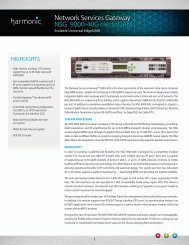
<strong>Harmonic</strong> <strong>ProStream</strong> <strong>1000</strong> is a highly integrated MPEG/DVB multiplexer, scrambler and<br />
descrambler, for multimedia services carried over digital broadcast networks. It features a<br />
modular, high-density chassis that is furnished with up to 5 IOMs (Input/Output Module) and<br />
up to 4 IPCs (Internal Processing Card) in a single one-rack-unit (1-RU) chassis. The<br />
modularity of the platform allows easy field replacement of cards, as well as field upgrades of<br />
SW and HW features.<br />
This guide describes the configuration and monitoring instructions for <strong>ProStream</strong> <strong>1000</strong>, a<br />
high density stream processing platform.<br />
1.2 Main Features<br />
The following table lists the main features of <strong>ProStream</strong> <strong>1000</strong>. The functionality of <strong>ProStream</strong><br />
<strong>1000</strong> depends on the installed IPC. <strong>ProStream</strong> <strong>1000</strong> functions as an encoder or transcoder<br />
according to the installed IPC type.<br />
Table 1-1: Main Firmware Related Features<br />
Category Feature Description<br />
Input and<br />
Output<br />
Interfaces<br />
Parsing<br />
Tables<br />
IP IOM Two independent ports per IP IOM<br />
line rate of 1 Gbps per IP IOM<br />
Maximum input and output bitrate is 500Mbps per<br />
IP IOM<br />
ASI SCR IOM ASI-SCR - up to four ports per IOM<br />
Inputs and outputs DVB-ASI streams<br />
Supports Common Scrambling Algorithm scrambling<br />
May synchronize the device to an external clock<br />
coming from a GPS receiver<br />
Bit rate:<br />
Maximum output bit rate of 187 Mbps<br />
Maximum input bit rate of 210 Mbps<br />
Supports packet size: 188 or 204 bytes<br />
Dynamic parsing of<br />
input<br />
Extracts incoming feeds and displays their structure and<br />
elements on the control interface. It displays their<br />
bitrate, CC errors, SI PSI structure etc’.<br />
Redundancy Input GbE port redundancy<br />
Socket redundancy for each input socket<br />
Service redundancy<br />
© 2012 <strong>Harmonic</strong> <strong>Inc</strong>. 7 <strong>ProStream</strong> <strong>1000</strong>, Version 6.2, Rev A
Chapter 1 Features and Specifications Main Features<br />
Processing<br />
Output<br />
Bit Rate<br />
Table 1-1: Main Firmware Related Features<br />
Category Feature Description<br />
Multiplexing/<br />
provisioning options of<br />
the device<br />
Maximum processing bit rate of 400 Mbps<br />
Full multiplexing (any input to any output)<br />
Multicast of any input stream to multiple transport<br />
streams.<br />
Multicast of services with different transcoding<br />
configuration<br />
IP multicast - supports IGMP ver 2/3<br />
Passing range of PIDs from any input to any output<br />
DiviTrack over IP Statistical multiplexing - combines rate shaping using<br />
external encoders<br />
DiviTrackMX (HW<br />
dependent, type of IPC)<br />
ReEncoding (HW<br />
dependent, type of IPC)<br />
Transcoding<br />
(HW dependent, type of<br />
IPC)<br />
Statistical multiplexing - combines rate shaping using<br />
internal encoders<br />
When re-encoding modules are mounted:<br />
Re-encodes incoming MPEG programs and outputs<br />
them with high video quality as follows:<br />
CBR - user-configurable constant bit rate<br />
DivTrackMX VBR - outputs pools of high quality, VBR<br />
HD/SD re-encoded programs. It increases<br />
bandwidth efficiency<br />
When transcoding modules are mounted:<br />
Transcodes incoming H264/MPEG2 programs and<br />
outputs them as H264/MPEG2 CBR/VBR services.<br />
SFN-over-IP MPEG-over-IP transport in DVB-T / DVB-H networks<br />
that operate in SFN mode. This includes ability to<br />
synchronize to an external GPS clock and external MIP<br />
inserter.<br />
Scrambling Supports the following scrambling algorithm:<br />
DVB-CSA<br />
AES-NSA2<br />
AES Fixed Key Control Word (CW) scrambling of<br />
outgoing TS over IP<br />
BISS<br />
Selective Encryption<br />
Functions as scrambler and in AES-CBC scrambling<br />
mode, also as de-scrambler<br />
Supports PSIG MUX protocol<br />
Supports ECMG redundancy<br />
Internal EIS<br />
Transcoding Bit Rate Video<br />
VBR - in a pool<br />
CBR - For HD up to 3 services per pool for best<br />
performances.<br />
Audio<br />
CBR only<br />
© 2012 <strong>Harmonic</strong> <strong>Inc</strong>. 8 <strong>ProStream</strong> <strong>1000</strong>, Version 6.2, Rev A
Chapter 1 Features and Specifications Main Features<br />
Output<br />
Monitoring<br />
Output<br />
Capabilities<br />
Table 1-1: Main Firmware Related Features<br />
Category Feature Description<br />
TS Mirroring TS Mirroring - Duplicates each output TS (master) from<br />
any interface (IP, ASI) to any other TS (slave) in any<br />
interface. Supports all master functions such as: rate<br />
shaping, scrambling, RSS, tables generation, common<br />
PCR, PID range, DToIP.<br />
IP Mirroring - Allows to duplicate all output data from<br />
one port (GbE1) of an IP IOM card to the other port<br />
(GbE2) of that card.<br />
SCT35 Insertion Receives an SNMP trap from SL 10 and generates an<br />
SCT35 cue message<br />
Table Generation Create CAT<br />
Create SDT<br />
Create NIT<br />
Table Re-generation PSIP re-generation<br />
EIT re-generation<br />
PID Prioritization In case of Over subscription, the <strong>ProStream</strong> <strong>1000</strong> starts<br />
dropping PIDs according to their priority.<br />
PID Range Allows to pass a range of PIDs from any input to any<br />
output.<br />
Up to 16 PID ranges per unit.<br />
Slate Any service can be configured to have an alternative, or<br />
backup input feed or source that is enabled on the<br />
output upon disruption of the primary feed. It allows<br />
MSOs to inform their subscribers that they are doing<br />
anything possible to restore the service.<br />
Splicing Allows cable headends and broadcast affiliates to insert<br />
locally-generated commercials and short programs into<br />
remotely distributed regional programs before they are<br />
delivered to home viewers<br />
Emergency Alert System<br />
(AES)<br />
Enable MSO to automatically broadcast emergency<br />
alert messages through pre-configured channels.<br />
PCR Input PCR The PCR can arrive on any input PID, such as video,<br />
audio or not on ES<br />
Output PCR The PCR can outflow on any PID. In transcoding,<br />
only over video PID<br />
Generate PCR<br />
Common PCR<br />
Management Management and<br />
monitoring interfaces<br />
Control Panel<br />
Web client<br />
NMX (<strong>Harmonic</strong>'s Digital Service Manager)<br />
© 2012 <strong>Harmonic</strong> <strong>Inc</strong>. 9 <strong>ProStream</strong> <strong>1000</strong>, Version 6.2, Rev A
2.1 Overview<br />
Chapter 2<br />
Logging into <strong>ProStream</strong> <strong>1000</strong><br />
In order to enhance the security of <strong>ProStream</strong> <strong>1000</strong>, the device has three access levels. Each<br />
access level applies to any form of communication with the device whether it is a web client<br />
or a Telnet session. Each access level offers a different mode of work with the device. The<br />
following table lists the various access levels and the available working modes:<br />
Access Level Working Mode<br />
Monitor Allows only to monitor the operation of the device.<br />
Configure Allows to configure the device only via a web client and to define<br />
the monitor access level password.<br />
The various access levels require a correct username and password combination.<br />
Username Password<br />
monitor monitor<br />
configure configure<br />
The current access level appears in the upper right hand corner of the web client.<br />
Title bar User name<br />
2.2 Full Device Configuration<br />
The <strong>ProStream</strong> <strong>1000</strong> web client allows a full configuration of the device. It also allows the<br />
user to monitor the <strong>ProStream</strong> <strong>1000</strong>'s status, view its alarms (if present), and troubleshoot<br />
them. This manual describes and instructs you on how to configure and monitor the device<br />
via the web client accessible through a web browser. The following table lists the web client<br />
specifications:<br />
Table 2-1: Web client Specifications<br />
Parameter Explanation<br />
Screen resolution 1280 x 1024<br />
Supported web browsers Microsoft Internet Explorer<br />
Versions 7, 8 and 9<br />
© 2012 <strong>Harmonic</strong> <strong>Inc</strong>. 10 <strong>ProStream</strong> <strong>1000</strong>, Version 6.2, Rev A
Chapter 2 Logging into <strong>ProStream</strong> <strong>1000</strong> Logging into the Device<br />
NOTE: Once you open any of the supported browsers, clean the cash. The browser may save previous GUI<br />
files. To clean cash, select Tools > Internet Options and in Browsing History click Delete.<br />
TIP: After upgrading the firmware of a <strong>ProStream</strong> <strong>1000</strong> device, clean cash as explained in the note above.<br />
2.3 Logging into the Device<br />
The following instructions guide you on how to login via a web client.<br />
1. In a browser, type in the address of the required device.<br />
2. Click Login.<br />
3. Type in the required username and password.<br />
4. To save the password for the future, select Remember my password.<br />
5. Click Ok.<br />
The web client page appears and you may start working with the device according to the<br />
restrictions of your access level.<br />
© 2012 <strong>Harmonic</strong> <strong>Inc</strong>. 11 <strong>ProStream</strong> <strong>1000</strong>, Version 6.2, Rev A
Chapter 2 Logging into <strong>ProStream</strong> <strong>1000</strong> Setting/Changing a Password<br />
2.4 Setting/Changing a Password<br />
To change a password, you do not need to click Apply. Once you enter all required<br />
information and click Change Password the new password is applied.<br />
1. Select Tools > Password section.<br />
2. If you logged in as Configure, you are authorized to change your password or the<br />
password of Monitor. In this case, the User Name field appears and you need to select<br />
either Monitor or Configure.<br />
3. In Current User Password, enter the required password.<br />
4. In New Password, enter the new password.<br />
5. In Verify Password, re-enter the new password.<br />
6. Click Change Password.<br />
When logging in use the newly set password.<br />
After three unsuccessful login trials, or if you forgot the password/user name, restore<br />
your password. To restore the password, see the following section.<br />
2.5 Restoring a Password<br />
In case you forget your password, you can restore it. You have three trials to login to the<br />
device. However, if you failed to log in, do the following:<br />
1. Upon your failed trial to login, a screen appears with the Specific Data Number.<br />
NOTE: The Specific Data Number is generated per each failed login.<br />
2. Record this unique number and immediately contact <strong>Harmonic</strong> Customer Support and<br />
provide customer support with the Specific Data Number.<br />
<strong>Harmonic</strong> Customer Support personnel provides you with a temporary password.<br />
3. Open your browser, and type the following:<br />
http:///resetpass.htm<br />
4. Click Go.<br />
Specific Data Number<br />
© 2012 <strong>Harmonic</strong> <strong>Inc</strong>. 12 <strong>ProStream</strong> <strong>1000</strong>, Version 6.2, Rev A
Chapter 2 Logging into <strong>ProStream</strong> <strong>1000</strong> Restoring a Password<br />
5. The Connect To dialog appears:<br />
6. In Username, type backdoor.<br />
7. In Password, type the password you received from <strong>Harmonic</strong> Customer Support.<br />
8. Once you logged into the device, set a password for future logins. See 2.4 Setting/<br />
Changing a Password on page 12.<br />
© 2012 <strong>Harmonic</strong> <strong>Inc</strong>. 13 <strong>ProStream</strong> <strong>1000</strong>, Version 6.2, Rev A
3.1 Overview<br />
Chapter 3<br />
Configuring and Provisioning<br />
Once the <strong>ProStream</strong> <strong>1000</strong> is properly cabled and setup in your network, you may access it<br />
via the web client in order to configure, provision and monitor it. The web client reads data<br />
from the device and presents it in an easy to use User Interface (UI).<br />
This chapter guides you on how to configure and multiplex a <strong>ProStream</strong> <strong>1000</strong> standalone<br />
model using the web client.<br />
NOTE: <strong>ProStream</strong> <strong>1000</strong> version 4.9 and up requires IE 7 and up.<br />
3.2 Web Client Page<br />
Tabs bar<br />
Title bar<br />
Input section Clock Logged in user<br />
Output section<br />
Input Properties<br />
section Buttons section<br />
Output Properties section<br />
The web client page includes the following sections:<br />
© 2012 <strong>Harmonic</strong> <strong>Inc</strong>. 14 <strong>ProStream</strong> <strong>1000</strong>, Version 6.2, Rev A
Chapter 3 Configuring and Provisioning Web Client Page<br />
Title bar - Indicates the <strong>ProStream</strong> model, its IP address, Alarm indicator, the current<br />
logged in username and the Apply button.<br />
Tabs bar- Links you to parameters required for <strong>ProStream</strong> configuration and provisioning.<br />
The available tabs are as follows:<br />
Platform - links you to the Platform page.<br />
Stream Config - links you to the Stream Config page.<br />
Status - links you to the Alarms page, the main monitoring page.<br />
Tools - allows you to set device time and required protocols<br />
CAS - links you to the CAS pages to configure CAS parameters and to view ECMs,<br />
SCGs and CWSs parameters.<br />
Support - links you to diagnostic information about the device<br />
Work area - Presents the parameters available for configuration and provisioning and<br />
allows to configure and provision the <strong>ProStream</strong>. It is divided into two sections: Input and<br />
Output. The work area changes according to the tab you have selected.<br />
Buttons section - <strong>Inc</strong>ludes multiplexing buttons. See Multiplexing Buttons on page 24.<br />
Clock - located at the Title bar. It displays the time of the device in the following format:<br />
mm/dd/yyyy hh:mm.<br />
3.2.1 <strong>ProStream</strong> Monitoring<br />
Monitoring the <strong>ProStream</strong> operation is very easy and straightforward. An alarm indicator is<br />
displayed in the title bar of each one of the available Web client pages. The Alarm indicator is<br />
actually a link to the Alarm page and the indicator provides the following information:<br />
Table 3-1: Alarm Indicators<br />
Alarm Indication Explanation<br />
Green Alarm button<br />
Red Alarm button<br />
Red Alarm button<br />
No active alarms.<br />
3.2.2 Stages of <strong>ProStream</strong> Configuration<br />
There is at least one active alarm. Once the mouse<br />
pointer hovers on it, a hint appears displaying the alarm<br />
description. Once you click it, the Alarm page opens.<br />
There is at least one active warning. Once the mouse<br />
pointer hovers on it, a hint appears displaying the alarm<br />
description. Once you click it, the Alarm page opens.<br />
N Active Alarms ‘N’ stands for the amount of registered alarms. Click the<br />
link to open the Alarm page.<br />
Configuring the <strong>ProStream</strong> standalone model includes the following stages:<br />
<strong>ProStream</strong> Platform Parameters - configure Ethernet ports, slots and ASI port direction.<br />
Usually, this configuration is a one time procedure performed as soon as you start<br />
configuring the device. You can also view chassis and GbE port parameters and define<br />
various global settings of the device.<br />
<strong>ProStream</strong> provisioning - during this stage you may read information from the device and<br />
then multiplex it. Multiplexing is done mainly from the Stream Config page and includes<br />
the following stages:<br />
Input configuration - enabling input ports and in case of GbE input port, setting port<br />
© 2012 <strong>Harmonic</strong> <strong>Inc</strong>. 15 <strong>ProStream</strong> <strong>1000</strong>, Version 6.2, Rev A
Chapter 3 Configuring and Provisioning Web Client Page<br />
and socket parameters.<br />
Reading data from the device (optional) - Web client displays the updated data as<br />
read from the device.<br />
Output configuration and multiplexing - in case of GbE port, setting port and socket<br />
parameters, setting TSs, services and PIDs parameters, arranging the output content<br />
(multiplexing) and setting output port parameters and enabling the port.<br />
Scrambling/Descrambling - when <strong>ProStream</strong> functions as a scrambler/descrambler, set<br />
communication parameters to allow communication between the device and the<br />
Conditional Access System (CAS). You may also view other CAS parameters such as SCG,<br />
ECM and EMM parameters.<br />
When <strong>ProStream</strong> functions as a descrambler using the AES protocol, set the CWS<br />
parameters.<br />
Encoding - when <strong>ProStream</strong> functions as a re-encoder, set the re-encoding parameters.<br />
Set these parameters via the Encoding tab.<br />
SFN over IP - when <strong>ProStream</strong> functions as a transmitter or receiver in a SFN over IP<br />
application, set the required parameters.<br />
3.2.3 Before you Begin<br />
Before you start configuring and provisioning the device, pay attention to the following:<br />
Fields that are for viewing only, are greyed out.<br />
To change parameter values, click in the field and type the required values. Once you<br />
click away from the field, the web client interface is updated and displays the new<br />
parameters. However, the parameters are not sent to the device.<br />
Every web page dialog includes a Done button. When clicking this button, you save the<br />
new configuration without applying it to the device and you close the web page dialog.<br />
To close a web page dialog without saving the configuration, click the button at the upper<br />
right corner of each page.<br />
To send to the device the newly configured parameters, click Apply. Only when you click<br />
Apply, you actually submit the new parameters to the device.<br />
To delete rows in a table, check the Select box and then click Delete Selected.<br />
© 2012 <strong>Harmonic</strong> <strong>Inc</strong>. 16 <strong>ProStream</strong> <strong>1000</strong>, Version 6.2, Rev A
Chapter 3 Configuring and Provisioning Platform Parameters<br />
3.3 Platform Parameters<br />
Configure the platform parameters when you start the device configuration. Usually it is a one<br />
time procedure that you do via the Platform page. The Platform page is the default page, it<br />
opens as soon as you link to the device:<br />
The Platform page is comprised of a graphical view of the <strong>ProStream</strong> back panel and as you<br />
select each component, a table presenting its parameters appears. The table allows you to<br />
configure and view various parameters.<br />
3.3.1 Setting ETH1-3 Parameters<br />
The IP address of the ETH3 port or <strong>ProStream</strong> primary IP address is configured as part of the<br />
<strong>ProStream</strong> installation (see <strong>ProStream</strong> Installation and Start Up User’s Guide). However, when<br />
required, you may change the IP address settings via the Platform screen, Ethernet table:<br />
To change configuration of ETH1, ETH2 and ETH3<br />
NOTE: Configure the IP address of ETH3 on a different subnet than that of ETH2. Configuring both ports<br />
to be on the same subnet may result in serious network communication problems. <strong>ProStream</strong> uses the<br />
ETH3 port to communicate with the network for management purposes and ETH2 for Conditional Access<br />
Systems (CAS) purposes.<br />
1. In Platform, select the required Ethernet port.<br />
2. In the table that appears, type the required IP address, subnet mask and default gateway.<br />
3. Click Apply to apply changes.<br />
4. In case you configured ETH3, login to the new IP address.<br />
NOTE: The MAC address is the physical address of the unit. The address is retrieved and presented in the<br />
Platform page for viewing purposes only.<br />
© 2012 <strong>Harmonic</strong> <strong>Inc</strong>. 17 <strong>ProStream</strong> <strong>1000</strong>, Version 6.2, Rev A
Chapter 3 Configuring and Provisioning Platform Parameters<br />
3.3.2 Viewing/Setting Chassis Parameters<br />
1. Select the Platform tab.<br />
2. Select Chassis/Main Card.<br />
3. In the Chassis Properties table, view the following chassis parameters:<br />
SW Version - indicates the firmware version.<br />
RAM Size - indicates the RAM size of the device. In this case the chassis supports 1Giga<br />
RAM.<br />
Chassis Serial Number - the serial number of the chassis.<br />
Hardware Revision - the revision of the Central Processing Card.<br />
Internal Part Number - indicates hardware configuration.<br />
Chassis Type - indicates chassis type.<br />
Part Number - customer part number.<br />
Boot Version - indicates the boot flash version.<br />
CPC Part Number - part number of the CPC card and its version.<br />
Midplane Part Number - indicates the part number and revision.<br />
Unit Name - type in the required device name.<br />
3.3.3 Viewing/Setting Card Parameters<br />
1. Select the Platform tab.<br />
2. Select the required slot. Each slot provides the following information:<br />
View slot information<br />
© 2012 <strong>Harmonic</strong> <strong>Inc</strong>. 18 <strong>ProStream</strong> <strong>1000</strong>, Version 6.2, Rev A
Chapter 3 Configuring and Provisioning Platform Parameters<br />
Slot # - the number of the slot as in the back panel of the device.<br />
Slot # list - allows you to select another IOM card when required.<br />
Actual - indicates the IOM card that is currently mounted in the slot.<br />
Table 3-2: Actual IOM Card<br />
Icon of<br />
Actual Card<br />
ASI IOM card<br />
3. To select the required card in the slot, open the Slot # list, and select the required card:<br />
None - no IOM card in the slot<br />
ASI - ASI IOM card<br />
ASI SCR - ASI IOM with scrambling support<br />
GbE Pro - GbE IOM card<br />
Explanation<br />
ASI SCR IOM card<br />
GbE Pro IOM card<br />
8VSB card<br />
8VSB card. See 8VSB Modulation on page 86.<br />
The Card# Properties table is updated to display the following:<br />
For an ASI or ASI SCR IOM Card - view or set the required port direction.<br />
View properties<br />
Set port direction<br />
© 2012 <strong>Harmonic</strong> <strong>Inc</strong>. 19 <strong>ProStream</strong> <strong>1000</strong>, Version 6.2, Rev A
Chapter 3 Configuring and Provisioning Platform Parameters<br />
For a GbE IOM card - in the Card# Properties table, view the type, serial number and the<br />
part number of the card.<br />
For 8VSB card - in the Card# Properties table, view the type, serial number and the part<br />
number of the card.<br />
3.3.4 Global Platform Configuration<br />
The Auxiliaries section allows you to apply global platform configuration according to the<br />
following explanations:<br />
To identify unit<br />
In Platform under Auxiliaries, click Identify Unit.<br />
The Local LED on the <strong>ProStream</strong> front and back panel turns on and the button toggles to<br />
Stop Identify.<br />
To reset the unit<br />
1. In Platform under Auxiliaries, click Reset Unit.<br />
2. Confirm the action by clicking OK.<br />
3. Wait until the procedure is complete.<br />
To clear configuration<br />
1. In Platform under Auxiliaries, click Clear Configuration.<br />
2. Confirm the action by clicking Ok.<br />
The previous configuration is removed and the device boots up with the default<br />
configuration.<br />
© 2012 <strong>Harmonic</strong> <strong>Inc</strong>. 20 <strong>ProStream</strong> <strong>1000</strong>, Version 6.2, Rev A
Chapter 3 Configuring and Provisioning Platform Parameters<br />
To download the Loader utility<br />
1. In Platform under Auxiliaries, click Loader Utility.<br />
2. Navigate to the location of your choice and click Save.<br />
3. The Loader utility is saved to the required location and you may start using it.<br />
To manage software versions<br />
In Platform under Auxiliaries, click Manage Software. For detailed information and instructions,<br />
refer to Managing Software on page 21.<br />
To access a wizard<br />
Click Wizards to open the Wizards page. See Working with Wizards on page 23.<br />
To verify that Validation system is active<br />
By default a validation system is active when using the web client. The validation system is<br />
checking the validity of the newly entered values. It is strongly recommended to configure<br />
and provision the device with the Validation box selected.<br />
3.3.5 Managing Software<br />
The Software Management page allows you to do the following:<br />
Transfer and install an updated version<br />
Change the running software - Up to two versions of the software package may reside on<br />
the <strong>ProStream</strong> device. Usually, the current installed version and the previous installed<br />
version. You may change the running software as required.<br />
To transfer and install an updated firmware version<br />
1. From <strong>Harmonic</strong> FTP site, download the zipped folder of the updated version.<br />
2. Unzip the folder.<br />
© 2012 <strong>Harmonic</strong> <strong>Inc</strong>. 21 <strong>ProStream</strong> <strong>1000</strong>, Version 6.2, Rev A
Chapter 3 Configuring and Provisioning Platform Parameters<br />
3. In Platform, in Auxiliaries, click Manage Software.<br />
The Software Management dialog appears.<br />
4. Click Install Software Package.<br />
The Transfer Software dialog appears.<br />
5. Click Browse and navigate to the location of the unzipped folder and select the file of the<br />
following format:xx.xx.xx.xxx (the file does not have an extension.)<br />
6. Click Transfer.<br />
A message appears notifying that the transfer may take a few minutes.<br />
7. Click Ok.<br />
The selected package is transferred and installed on the device. Progress bars and<br />
flashing messages appear indicating the stages and progress of the version transfer and<br />
installation.<br />
CAUTION: During software transfer leave the Internet Explorer open and do not reset the device. Either<br />
action may cause the device to hang without a valid firmware for booting up.<br />
Once the transfer is complete, a message appears asking you whether the device should<br />
run with the newly transferred version.<br />
8. Click Ok.<br />
A message appears asking you whether to reset.<br />
9. Click Ok to reset and run the device with the newly transferred version.<br />
A message appears asking you whether to close the web client.<br />
10. Click Yes to close the web client page. This is the recommended option.<br />
If you click No, the web client page stays open during reset, but it cannot read data from<br />
the device to display updated information.<br />
11. Wait a few minutes until reset is complete and open the web client page.<br />
To organize the loaded software versions<br />
1. In Platform, click Manage Software.<br />
The Software Management dialog appears.<br />
2. Open the Software Version list to select the required version.<br />
3. Do either of the following:<br />
To select a version to be installed after reset, click Select. A message appears<br />
© 2012 <strong>Harmonic</strong> <strong>Inc</strong>. 22 <strong>ProStream</strong> <strong>1000</strong>, Version 6.2, Rev A
Chapter 3 Configuring and Provisioning What’s Next<br />
notifying you that the selection completed successfully and asking you whether to<br />
reset the device. Once you click Ok, the device reboots to run with the newly selected<br />
version.<br />
To remove a version from the device, click Remove.<br />
NOTE: You can have up to three software versions loaded on the device.<br />
3.3.6 Working with Wizards<br />
The built-in wizards streamline the configuration of the following:<br />
Routing a large number of sockets<br />
In SFN application - configuring the Transmitter and Receiver devices<br />
To select and use a wizard<br />
1. In the web client page, select Platform.<br />
2. Under Auxiliaries, click Wizards.<br />
3. Open the Wizards list and select either of the following:<br />
SFN Receiver Configuration - for receiver configuration<br />
SFN Transmitter Configuration - for transmitter configuration<br />
SPTS Socket Routing Configuration - for routing input SPTS sockets to output SPTS<br />
sockets.<br />
The Description and Parameters sections are updated according to the selected wizard.<br />
4. Enter the required parameters.<br />
5. Click Run to process the configuration This process may take a few seconds.<br />
6. Click Apply to send the configuration to the device.<br />
7. To return to the Platform page, click the Platform tab.<br />
3.4 What’s Next<br />
To continue with the configuration, familiarize yourself with the Stream Config page. The<br />
Stream Config page allows you to continue with the configuration.<br />
© 2012 <strong>Harmonic</strong> <strong>Inc</strong>. 23 <strong>ProStream</strong> <strong>1000</strong>, Version 6.2, Rev A
Chapter 3 Configuring and Provisioning Stream Config page<br />
3.5 Stream Config page<br />
The Stream Config page enables to view the input and output ports and to configure them.<br />
The page reflects the cards mounted in the device <strong>ProStream</strong> and reads and displays data<br />
from the input ports. The following figure shows the Stream Config page:<br />
Input section<br />
Input Properties section<br />
The Stream Config page always includes the following sections:<br />
Input section - displays the input ports according to the mounted card and allows to<br />
update the display by reading the current input from the input ports.<br />
Input Properties section - allows to enable a port and to configure the port’s settings. This<br />
section changes according to the item selected in the Input section.<br />
Output section - displays the available output ports and their provisioned output TSs.<br />
Output Properties - allows to configure the output ports, TSs, services and PIDs.<br />
Multiplexing buttons:<br />
Table 3-3: Multiplexing Buttons<br />
Output section<br />
Multiplexing buttons Output Properties section<br />
Button Button Name Selected Output Parameter<br />
Add to Output from input Any beside PID Allocation<br />
Remove from Output Any beside PID Allocation<br />
© 2012 <strong>Harmonic</strong> <strong>Inc</strong>. 24 <strong>ProStream</strong> <strong>1000</strong>, Version 6.2, Rev A
Chapter 3 Configuring and Provisioning Stream Config page<br />
Table 3-3: Multiplexing Buttons<br />
Button Button Name Selected Output Parameter<br />
New Service Any beside PID Allocation<br />
New PID Any beside PID Allocation<br />
PID Range - moves a PID<br />
range from the input to the<br />
output<br />
Any beside PID Allocation<br />
New Reference Service Any beside PID Allocation<br />
New ECM PID Allocation<br />
New EMM PID Allocation<br />
New ECM PID Hierarchy, TS, audio/video<br />
PID<br />
New EMM PID Allocation<br />
New Pool Any beside PID Allocation<br />
ReAlloc TransEngines - to<br />
optimize transcoding<br />
performance following the<br />
Could not Allocate<br />
Transcoding Unit alarm.<br />
View Input - click to view<br />
input extraction of object<br />
selected in output.<br />
New Service In - click to<br />
create a service in the<br />
input. Toggles to Delete<br />
Service In when the<br />
service is selected in the<br />
input.<br />
Hierarchy<br />
Service and audio/video PID<br />
Select a TS in the Input<br />
section.<br />
NOTE: Once you read input information and then open another page, read input information again when<br />
reopening the Stream Config page.<br />
© 2012 <strong>Harmonic</strong> <strong>Inc</strong>. 25 <strong>ProStream</strong> <strong>1000</strong>, Version 6.2, Rev A
Chapter 3 Configuring and Provisioning Stream Config page<br />
3.5.1 Stream Config page Conventions<br />
The following table lists the icons used in the Stream Config page and the information<br />
provided next to the icon:<br />
Table 3-4: Stream Config Conventions<br />
Icon Explanation Additional Info.<br />
Arrowhead is yellow - active Port<br />
Arrowhead is grey - inactive Port.<br />
The port type name is italicized.<br />
(ASI, GbE)<br />
Transport Stream (TS) TS ID and either of the following:<br />
GbE - (IP:UDP) index #<br />
ASI - (# of services)<br />
Descrambled Transport Stream<br />
(TS)<br />
TS ID and either of the following:<br />
GbE - (IP:UDP) index #<br />
ASI - (# of services)<br />
TS Mirror This TS is mirroring another TS<br />
Pool For future use. Pool ID and its bit rate<br />
Multiplexed ECM PID number<br />
EMM PID PID number<br />
Video PID PID number<br />
Audio PID. PID number<br />
Audio PID of type MPEG1L2,<br />
usually ES 0x3/4<br />
Audio PID of type AC3, usually ES<br />
0x81<br />
PID number<br />
PID number<br />
SCTE35 PID PID number<br />
Private Data PID, Ghost PID, or<br />
Range of PIDs<br />
PID allocation for ECMs and<br />
EMMs<br />
PID number<br />
PCR PID PID number<br />
Service, Reference Service Service name and ID<br />
© 2012 <strong>Harmonic</strong> <strong>Inc</strong>. 26 <strong>ProStream</strong> <strong>1000</strong>, Version 6.2, Rev A
Chapter 3 Configuring and Provisioning What’s Next<br />
Table 3-4: Stream Config Conventions<br />
3.6 What’s Next<br />
Icon Explanation Additional Info.<br />
Now you are ready to start configuring the <strong>ProStream</strong> unit and provision services through it.<br />
NOTE: GbE input/output port should be configured before provisioning services through the port.<br />
3.7 Configuring Input Ports<br />
Re-encoded service Service name and ID<br />
Scrambled service Service name and ID<br />
Transcoded service in a pool Service name and ID and pool name<br />
<strong>ProStream</strong> devices may have GbE and/or ASI input ports. Each port may be individually<br />
enabled or disabled. The configuration of the input ports is done through the Stream Config<br />
page.<br />
The Input port configuration consists of the following stages:<br />
Set port mode of work - applicable only to GbE ports.<br />
Enable/disable ports - applicable to all types of input ports.<br />
Set port parameters - applicable to GbE ports only.<br />
Set socket parameters - applicable to GbE ports only.<br />
Read the current information from input ports. (optional)<br />
3.7.1 Setting the Mode of Work of the Port<br />
1. In the Input section, select a GbE card.<br />
The Main section is updated accordingly.<br />
2. Open the Ports Usage list and select one of the methods for using the GbE input ports.<br />
Ports may work independently or in a redundancy mode. The redundancy modes are<br />
listed in table Table 3-5 on page 28.<br />
Note the following regarding port redundancy:<br />
By default, port 1 is the primary port and port 2 of the same IOM module is the<br />
backup port.<br />
Triggers of port redundancy switch are: Missing PID, Zero Bitrate (Cable Disconnect,<br />
Socket Loss), PAT/PNT Missing, CC Error.<br />
© 2012 <strong>Harmonic</strong> <strong>Inc</strong>. 27 <strong>ProStream</strong> <strong>1000</strong>, Version 6.2, Rev A
Chapter 3 Configuring and Provisioning Configuring Input Ports<br />
The following table lists the supported redundancy modes:<br />
Table 3-5: GbE Input Redundancy modes<br />
Parameter Explanation<br />
Independent Ports Each port receives another feed.<br />
Manual The redundancy switch is performed manually. The Active Port<br />
parameter appears and you can set the active port.<br />
Automatic The redundancy switch is performed automatically upon port<br />
failure. Once the primary is faulty, the device automatically switches<br />
to the backup port and continues receiving content over this port<br />
unless it is faulty. The device switches to the primary port only<br />
when the backup fails.<br />
Manual Revert The redundancy switch is performed automatically upon port<br />
failure. However, switching back to the primary, when fixed, is<br />
performed manually.<br />
To revert back to the primary port, you should change the Port<br />
Usage to Automatic. Once the primary port is active, change Port<br />
Usage to Manual Revert.<br />
Automatic Revert The redundancy switch is performed automatically upon port<br />
failure. However, the device automatically switches to the primary<br />
when the primary has stabilized and even though the backup is still<br />
in order. The baseline is that the primary is preferred.<br />
3.7.2 Configuring the Input ASI Ports<br />
NOTE: Prior to configuration, define whether the ASI port is an input or output port. See Viewing/<br />
Setting Card Parameters on page 18. By default the port is an input port.<br />
1. In the Input section, select a port.<br />
The Main section is updated accordingly.<br />
2. ‘To enable the port, select Enable Port.<br />
TIP: Enable the port only once port configuration is complete.<br />
3. In Description, edit the default description.<br />
4. In Packet Size, select the required packet size.<br />
You may select 188 (default) or 204 or Auto. In the latter, the <strong>ProStream</strong> automatically<br />
detects the packet size.<br />
In case of scrambling over ASI, you may select 188 (default) and 204 only.<br />
5. In Port Type, usually Regular Port appears. In SFN application, also 1PPS is available.<br />
6. Click Apply.<br />
The port is enabled and its data may flow into the device.<br />
© 2012 <strong>Harmonic</strong> <strong>Inc</strong>. 28 <strong>ProStream</strong> <strong>1000</strong>, Version 6.2, Rev A
Chapter 3 Configuring and Provisioning Configuring Input Ports<br />
3.7.3 Configuring the Input GbE Ports<br />
1. In the Input section, select a port.<br />
The Main tab is updated accordingly.<br />
2. To enable the port, select Enable Port.<br />
TIP: Enable the port only once port configuration is complete.<br />
3. In Disable on No Stream - if selected, when no stream is detected at the port, automatically<br />
port shifts to Link Down. Once stream is detected, port automatically shifts to Link Up.<br />
4. In Description, edit the default description.<br />
5. Do one of the following:<br />
To configure the port, click Port Configuration. See GbE Port Configuration on<br />
page 29.<br />
To configure the socket, click Sockets Configuration. See Socket Configuration on<br />
page 31.<br />
6. Click Apply.<br />
The port is enabled and its data may flow into the device.<br />
TIP: The following sections are relevant to GbE port only.<br />
3.7.3.1 GbE Port Configuration<br />
Configure the GbE input port according to the following provided instructions:<br />
To set Port definitions - GbE ports only<br />
1. Select the Input GbE port.<br />
2. In Input Properties, click Port Configuration.<br />
© 2012 <strong>Harmonic</strong> <strong>Inc</strong>. 29 <strong>ProStream</strong> <strong>1000</strong>, Version 6.2, Rev A
Chapter 3 Configuring and Provisioning Configuring Input Ports<br />
The following dialog appears:<br />
3. Configure and view the port parameters according to the following:<br />
IP Address - type in the required IP address.<br />
Subnet Mask - type in the required subnet mask.<br />
Gateway - type in the IP address of the gateway.<br />
Route1 IP Address - type in the required IP address.<br />
Route1 Subnet Mask - type in the required subnet mask.<br />
Route2 IP Address - type in the required IP address.<br />
Route2 Subnet Mask - type in the required subnet mask.<br />
MAC Address - (Read only) view the physical address of the GbE as retrieved from<br />
the device.<br />
SFP Vendor - (Read only) view the vendor of the SFP module mounted in the GbE<br />
port.<br />
SFP mode - (Read only) view the mode of the SFP module mounted in the GbE.<br />
SFP type - (Read only) view the type of SFP mounted. It can be either SX - usually<br />
used for short distances (up to 200 m) or LX - usually used for long distances (10km<br />
and up).<br />
Auto Negotiation - The Auto Negotiation is a handshake protocol used in GbE links.<br />
Select this check box to activate the Auto Negotiation protocol only if the other end<br />
of the GbE link also uses auto negotiation.<br />
© 2012 <strong>Harmonic</strong> <strong>Inc</strong>. 30 <strong>ProStream</strong> <strong>1000</strong>, Version 6.2, Rev A
Chapter 3 Configuring and Provisioning Configuring Input Ports<br />
Under Advanced Options, configure the following:<br />
TX Only - in case of a single direction link, select to define the port as a transmitting<br />
port.<br />
Inter Packet Gap - Applies to GbE output ports only. Enter the required internal<br />
packet gap. The minimum allowed gap is 12 ticks. If the gap is less than 12, the alarm<br />
The Inter Packet Gap is below 12 ticks is raised.<br />
Loopback Mode - select in case you wish to loopback the port, that is the data is sent<br />
back to the input port.<br />
4. Click Done to save the new configuration.<br />
3.7.3.2 Socket Configuration<br />
Content transmission of Video-over-IP utilizes sockets. Each socket is a terminal for a TS. The<br />
socket is defined by a unique combination of destination IP address and UDP port.<br />
You may add up to 128 sockets with up to eight MPTS (Multi Protocol Transport Services)<br />
sockets. Each MPTS socket may stream up to 32 services.<br />
NOTE: To change socket type (SPTS, MPTS), delete the socket and reconfigure with the new socket type.<br />
You may add sockets either one by one or multiple sockets in one step. In addition, you may<br />
delete sockets at any time.<br />
Socket IP Address<br />
When defining the IP address of a socket, follow the information provided below:<br />
Table 3-6:<br />
Type Class Available Range<br />
Unicast A 1.0.0.0 - 126.255.255.255<br />
Unicast B 128.0.0.0 - 191.255.255.255<br />
Unicast C 192.0.0.0 - 223.255.255.255<br />
Multicast D 224.0.0.0 - 239.255.255.255<br />
NOTE: The following reserved ranges should not be used:<br />
reserved 224.0.0.0 - 224.0.0.255,<br />
reserved for administration 239.0.0.0 - 239.255.255.255<br />
To set socket definitions - GbE ports only<br />
1. In the Input Properties section, click Sockets Configuration.<br />
© 2012 <strong>Harmonic</strong> <strong>Inc</strong>. 31 <strong>ProStream</strong> <strong>1000</strong>, Version 6.2, Rev A
Chapter 3 Configuring and Provisioning Configuring Input Ports<br />
The Sockets Configuration dialog appears:<br />
NOTE: This dialog is furnished with an horizontal and vertical scroll bars. To view the vertical scroll bar,<br />
scroll with the horizontal one to the right most side of the dialog. Scroll the horizontal one to view all<br />
configured sockets.<br />
2. Do either of the following:<br />
Edit the parameters of the required sockets according to the explanation below ( Defining<br />
Socket Parameters.<br />
Or,<br />
Add a socket as explained in Adding a Socket or Multiple Sockets on page 33.<br />
Defining Socket Parameters<br />
Define the socket parameters as follows:<br />
Sel - click to select the socket prior to using any of the buttons of the dialog.<br />
IP Address - enter an IP as explained in Socket IP Address on page 31.<br />
Port - enter a port number. The available range is 1- 65535.<br />
Encapsulation Mode - select one of the following:<br />
UDP - according to the transmitter/receiver<br />
RTP - according to the transmitter/receiver. If FEC is used, select RTP<br />
HRTP - to receive a socket encapsulated in <strong>Harmonic</strong> RTP to allow connection<br />
between <strong>ProStream</strong> <strong>1000</strong> devices.<br />
TCP - Input only. It applies to data with low rate that is transmitted over TCP<br />
TS Mode - select one the following:<br />
MPTS<br />
SPTS<br />
Data - see ADI Application Note.<br />
CAS DATA<br />
© 2012 <strong>Harmonic</strong> <strong>Inc</strong>. 32 <strong>ProStream</strong> <strong>1000</strong>, Version 6.2, Rev A
Chapter 3 Configuring and Provisioning Configuring Input Ports<br />
FEC - relates to the extra data that is sent on a separate socket(s) and includes the<br />
number of rows and columns to be calculated. Higher number of rows and columns,<br />
yields a higher overhead and a better error correction ability. Define the FEC parameters<br />
as follows:<br />
Descramble - select for Fixed Key descrambling. You can also configure this field in the<br />
Input Properties of a TS. When you select in the Descramble tab the Fixed Key option, this<br />
field is selected automatically<br />
Bitrate - enter the required bit rate.<br />
Adding a Socket or Multiple Sockets<br />
The following table lists the available methods for adding a socket:<br />
1. In the Socket Configuration page, click Add Socket.<br />
The Add sockets page appears.<br />
2. To add a single socket, do the following:<br />
1. Define the IP Address (see Socket IP Address on page 31) and the port number.<br />
2. Click Done.<br />
Option Explanation<br />
No FEC No Forward Error Correction is applied<br />
Pro-MPEG Annex B/SMPE 2022 Annex C FEC standard. Select to read input with FEC<br />
data<br />
Table 3-7: Adding a Socket<br />
Button Explanation<br />
Adds a single socket with the last socket<br />
configuration with an incremented IP address<br />
The socket is added to the list. Continue the configuration as explained in Defining<br />
Socket Parameters on page 32.<br />
3. To add multiple sockets, select Add Multiple Sockets.<br />
Adds a single socket with the last socket<br />
configuration with an incremented port number<br />
Adds a single socket or multiple sockets<br />
© 2012 <strong>Harmonic</strong> <strong>Inc</strong>. 33 <strong>ProStream</strong> <strong>1000</strong>, Version 6.2, Rev A
Chapter 3 Configuring and Provisioning Configuring Input Ports<br />
1. Select Add Multiple Sockets.<br />
The Num of Ports parameter is added to the table.<br />
2. Define the IP Address (see Socket IP Address on page 31) and the UDP port.<br />
3. In Num of IPs, enter the amount of IPs you wish to add.<br />
4. In Num of Ports, enter the amount of UDP ports you wish to add.<br />
5. Click Done.<br />
Multiple sockets are added to the list. Continue the configuration as explained in<br />
Defining Socket Parameters on page 32.<br />
Adding a Single Socket with <strong>Inc</strong>remented Port Number<br />
In the Socket Configuration page, click Duplicate Last Socket (<strong>Inc</strong> Port).<br />
The configuration of the last socket is duplicated and is the configuration of the newly<br />
added socket. The port number of the newly added socket is incremented by one.<br />
Newly added socket with same configuration as<br />
previous one and an incremented port number<br />
Adding a Single Socket with <strong>Inc</strong>remented IP Address<br />
In the Socket Configuration page, click Duplicate Last Socket (<strong>Inc</strong> IP).<br />
The configuration of the last socket is duplicated and is the configuration of the newly<br />
added socket. The IP address of the newly added socket is incremented by one.<br />
Newly added socket with same configuration as<br />
previous one and an incremented IP address<br />
Now you are ready to enable the GbE port as explained in Configuring the Input ASI Ports on<br />
page 28.<br />
© 2012 <strong>Harmonic</strong> <strong>Inc</strong>. 34 <strong>ProStream</strong> <strong>1000</strong>, Version 6.2, Rev A
Chapter 3 Configuring and Provisioning Input Information (Extraction)<br />
To edit the socket list<br />
1. To delete a socket, check the Select box of a socket you wish to cancel.<br />
2. Click Delete Selected.<br />
The required socket is deleted.<br />
3.8 Input Information (Extraction)<br />
To read/refresh input information from the Input port<br />
To refresh input information, click Refresh Input Information.<br />
The display is updated as the application retrieves the information. When this is the first<br />
time you are reading information the icon appears next to the port to indicate that you<br />
may look at its content.<br />
3.8.1 Viewing/Configuring Input Information<br />
Both Input and Input Properties sections provide information on the input stream.<br />
3.8.1.1 Input section<br />
The Input section provides a general view of the input stream and you may drill down a slot to<br />
view its components, that is the mounted card. Drill down the card to view its components.<br />
To view the Slot components<br />
Click, next to the required slot.<br />
The components of the slot, that is the mounted card appear.<br />
To view the Card components<br />
Click, next to the required card.<br />
The components of the card, that is the ports appear. You can also configure port usage,<br />
see Setting the Mode of Work of the Port on page 27.<br />
To view the Port components<br />
Click, next to the required port.<br />
The components of the port, that is the TSs appear.<br />
Usually, each port appears with its port number and bit rate in kbps. If you drill down a<br />
port you may view its TSs.<br />
To view the components of a TS<br />
Click, next to the required TS/service.<br />
© 2012 <strong>Harmonic</strong> <strong>Inc</strong>. 35 <strong>ProStream</strong> <strong>1000</strong>, Version 6.2, Rev A
Chapter 3 Configuring and Provisioning Input Information (Extraction)<br />
The components of the TS/service appear. If you drill down a service you may view its<br />
PIDs. In case the TS includes PSIP tables, the PIDs of the PSIP tables appear as ghost<br />
PIDs. The ghost PID 0x1FFB always appears and the appearance of the other ghost PIDs<br />
depends on the PSIP data.<br />
Usually TSs appear with their ID number, for GbE port - socket, and number of services<br />
included in the TS.<br />
However TSs may be disabled or unknown as the following table lists:<br />
NOTE: In case of an ASI input/output port, the Input/Output section allows you to set the packet size.<br />
See, Configuring the Input ASI Ports on page 28.<br />
3.8.2 Input Properties section<br />
3.8.2.1 GbE Card<br />
Table 3-8: TS Information at the Input Port<br />
The Input Properties section provides essential information on an item selected in the Input<br />
section. This information is read only and may help you while provisioning the output stream.<br />
The following tables list the information displayed in the Input Properties according to the<br />
selected item in the Input section:<br />
Define the Port Usage, see Setting the Mode of Work of the Port on page 27.<br />
3.8.2.2 ASI Port Information<br />
TS Status Explanation<br />
Enabled TS appears with ID number.<br />
ASI port - also number of services and bitrate<br />
GbE port - also socket information, number of<br />
services, bitrate and TS index number<br />
Disabled The port is disabled. Also TS services are disabled.<br />
Unknown Port is enabled and data is flowing in, however<br />
<strong>ProStream</strong> cannot extract input data.<br />
See Configuring the Input ASI Ports on page 28.<br />
GbE Port - TS<br />
ASI Port - TS<br />
© 2012 <strong>Harmonic</strong> <strong>Inc</strong>. 36 <strong>ProStream</strong> <strong>1000</strong>, Version 6.2, Rev A
Chapter 3 Configuring and Provisioning Input Information (Extraction)<br />
3.8.2.3 GbE Information<br />
See Configuring the Input GbE Ports on page 29.<br />
3.8.2.4 ASI TS Information<br />
When you select a TS in the Input section and the TS flows into the device over an ASI port,<br />
the following information appears in the Input Properties section:<br />
Table 3-9: ASI TS EXtraction<br />
3.8.2.5 GbE TS Extraction<br />
Parameter Explanation<br />
TS ID The ID number of the selected TS.<br />
PAT Version The PAT’s (Program Association Table) version<br />
identification. This version is incremented every<br />
time the PAT’s data is changed.<br />
NIT PID The PID of the Network Information Table.<br />
Extract. Mode Allows you to select the requested extraction.<br />
See Selecting Extraction Mode on page 40.<br />
Show CC Errors Whether to show Continuity Counter errors,<br />
select one of the following options:<br />
Always<br />
Never<br />
Passed through PIDs<br />
When you select a TS in the Input section and the TS flows in the device over a GbE port, the<br />
following information appears in the Input Properties section:<br />
General tab<br />
© 2012 <strong>Harmonic</strong> <strong>Inc</strong>. 37 <strong>ProStream</strong> <strong>1000</strong>, Version 6.2, Rev A
Chapter 3 Configuring and Provisioning Input Information (Extraction)<br />
Table 3-10: GbE TS Extraction - General tab<br />
Parameter Explanation<br />
TS ID The ID number of the selected TS.<br />
PAT Version The PAT’s (Program Association Table) version identification. This<br />
version is incremented every time the PAT’s data is changed.<br />
NIT PID The PID of the Network Information Table.<br />
Extract. Mode Allows you to select the requested extraction. See Selecting<br />
Extraction Mode on page 40<br />
TS-Mode Allows you to select the requested TS mode: SPTS, MPTS, or Data<br />
Show CC Errors For Continuity Counter errors, select one of the following options:<br />
Always<br />
Never<br />
For Passed PIDs Only<br />
Elapsed Time for<br />
Socket Fail<br />
Descramble tab<br />
Define, in seconds, the elapsed time between detecting a<br />
problem in the input port and raising the Socket Fail alarm.<br />
FEC Indicates FEC parameters when configured to read input with FEC<br />
parameters. See Defining Socket Parameters on page 32.<br />
De-Jittering Select to recover video directly from the jittered and noisy frames.<br />
De-Jittering should be unchecked for:<br />
CAS Data IP input TS.<br />
When SFN is enabled, Low Delay=1<br />
Table 3-11: GbE TS Extraction - De-scramble tab<br />
Parameter Explanation<br />
No Descrambling select when De-scrambling is not required<br />
CWS Usage select in AES application<br />
Fixed Key Usage select when fixed key is required<br />
© 2012 <strong>Harmonic</strong> <strong>Inc</strong>. 38 <strong>ProStream</strong> <strong>1000</strong>, Version 6.2, Rev A
Chapter 3 Configuring and Provisioning Input Information (Extraction)<br />
Primary<br />
Table 3-12: GbE TS Extraction - Primary tab<br />
Backup<br />
Parameter Explanation<br />
Socket IP Enter the IP address of the socket<br />
Socket UDP Enter the required UDP<br />
Encapsulation Mode Select the required encapsulation mode<br />
FEC Select whether to read input with FEC.<br />
See Defining Socket Parameters on page 32.<br />
SSM Source Specific Multicast. This feature allows you to define<br />
up to four different sources for the TS by entering the IP<br />
address of the upstream transmitting devices. This feature<br />
is relevant only when working in GMPv3.<br />
Backup socket should have the same content as the primary socket. However, primary and<br />
backup can have different Encapsulation mode, FEC and a set of SSM addresses.<br />
NOTE: You can define a backup socket on the same port as the primary or on a different port but it<br />
should be on the same IOM module.<br />
Table 3-13: GbE TS Extraction - Backup tab<br />
Parameter Explanation<br />
Socket IP Enter the IP address of the backup socket<br />
Socket UDP Enter the required UDP<br />
© 2012 <strong>Harmonic</strong> <strong>Inc</strong>. 39 <strong>ProStream</strong> <strong>1000</strong>, Version 6.2, Rev A
Chapter 3 Configuring and Provisioning Input Information (Extraction)<br />
Table 3-13: GbE TS Extraction - Backup tab<br />
3.8.2.6 Selecting Extraction Mode<br />
1. In Input, select a TS.<br />
2. In Input Properties, select the required extraction mode:<br />
Disable - no extraction is available<br />
Ghosts only - displays all PIDs of the TS as ghost PIDs.<br />
PSI only - extracts the PAT PMT and CAT tables.<br />
PSI + SI - extracts the PAT, PMT, CAT, SDT and NIT tables.<br />
PSIP - extracts the supported PSIP tables.<br />
3. Click Apply.<br />
4. Click Refresh Input.<br />
The TS appears with the required extraction mode.<br />
3.8.3 GbE Input Redundancy<br />
Parameter Explanation<br />
Encapsulation Mode Select the required encapsulation mode<br />
FEC Select whether to read input with FEC.<br />
See Defining Socket Parameters on page 32.<br />
SSM Source Specific Multicast. This feature allows you to define<br />
up to four different sources for the TS by entering the IP<br />
address of the upstream transmitting devices. This feature<br />
is relevant only when working in GMPv3.<br />
Backup Scr From Same Physical Port - primary and backup sockets are<br />
on the same physical port<br />
Other Physical Port - primary and backup ports are on<br />
different ports of the same IOM module<br />
The following section describes the redundancy mechanism for input GbE ports and sockets.<br />
Configuring socket redundancy includes the following stages:<br />
Configuring a primary and a backup socket.<br />
Backup socket should have the same content as the primary socket. However, primary<br />
and backup can have different Encapsulation mode, FEC and a set of SSM addresses.<br />
You can define a backup socket on the same port as the primary or on a different port<br />
but it should be on the same IOM module.<br />
Selecting the required redundancy mode. The following table lists the available modes:<br />
Table 3-14: GbE Input Redundancy modes<br />
Parameter Explanation<br />
None No redundancy is required<br />
© 2012 <strong>Harmonic</strong> <strong>Inc</strong>. 40 <strong>ProStream</strong> <strong>1000</strong>, Version 6.2, Rev A
Chapter 3 Configuring and Provisioning Input Information (Extraction)<br />
Table 3-14: GbE Input Redundancy modes<br />
Parameter Explanation<br />
Manual The redundancy switch is performed manually<br />
Automatic The redundancy switch is performed automatically<br />
according to the predefined triggers.<br />
The device automatically switches between<br />
primary and backup according to their activation<br />
status. Switching from the active one to the non<br />
active occurs upon failure on the active one and<br />
while the non active is in order.<br />
Manual Revert The redundancy switch is performed automatically<br />
according to the predefined triggers. However,<br />
switching back to the primary, when fixed, is<br />
performed manually.<br />
Automatic Revert The redundancy switch is performed automatically<br />
according to the predefined triggers. However,<br />
the device automatically switches to the primary<br />
when the primary is stabilized and even though<br />
the backup is still in order. The baseline is that the<br />
primary is preferred. For each trigger you can<br />
define the stabilized time. See Configuring<br />
Redundancy for GbE Input Socket - Automatic<br />
Revert Mode on page 44.<br />
Defining redundancy triggers per socket<br />
In cas you select Automatic revert, configure stabilization time per redundancy trigger.<br />
3.8.3.1 Configuring Redundancy for GbE Input Socket - Manual Mode<br />
1. Open the device browser and login. See Logging into the Device on page 11.<br />
2. Select the Stream Config tab.<br />
3. In the Input section, select the required socket and the Redundancy tab.<br />
4. Open the Mode list and select Manual.<br />
In the Redundancy tab, the following takes place:<br />
Mode is Manual View the currently<br />
activated socket<br />
Select the redundancy tab<br />
Open the Mode list and select<br />
Manual<br />
Select the active<br />
socket<br />
© 2012 <strong>Harmonic</strong> <strong>Inc</strong>. 41 <strong>ProStream</strong> <strong>1000</strong>, Version 6.2, Rev A
Chapter 3 Configuring and Provisioning Input Information (Extraction)<br />
The activated option appears<br />
The Backup tab appears<br />
5. View the current active socket.<br />
6. In Active, select the required socket. In case the primary failed, open the Active list and<br />
select Backup to perform a manual redundancy switch.<br />
7. Select the Primary tab and configure the primary socket. See GbE TS Extraction on<br />
page 37.<br />
8. Select the Backup tab and configure the backup socket. See GbE TS Extraction on<br />
page 37.<br />
3.8.3.2 Configuring Redundancy for GbE Input Socket - Automatic Mode<br />
When selecting the Automatic mode, configure the triggers for the redundancy switch.<br />
By default, the alarm Socekt Not Active is always a trigger. You can view the elapsed time<br />
between detecting a problem in the input port and raising the Socket Fail alarm. To configure<br />
this threshold, see Table 3-10 on page 38.<br />
For other triggers, define whether to activate them as triggers for the redundancy switch and<br />
the threshold for the redundancy switch.<br />
The Bitrate Underflow and the Scrambled A/V triggers raise an alarm only when they are<br />
enabled triggers.<br />
To configure redundancy Automatic mode<br />
1. Open the device browser and login. See Logging into the Device on page 11.<br />
2. Select the Stream Config tab.<br />
3. In the Input section, select the required socket and the Redundancy tab.<br />
4. Open the Mode list and select Automatic.<br />
In the Redundancy tab, the following takes place:<br />
Indication of the activated socket appears<br />
The Backup tab appears<br />
Triggers section appears<br />
Select the redundancy tab<br />
Open the Mode list and select<br />
Manual<br />
View the currently<br />
activated socket<br />
Configure the<br />
triggers<br />
© 2012 <strong>Harmonic</strong> <strong>Inc</strong>. 42 <strong>ProStream</strong> <strong>1000</strong>, Version 6.2, Rev A
Chapter 3 Configuring and Provisioning Input Information (Extraction)<br />
5. View the following:<br />
View the currently activated socket<br />
View the threshold for Socket Not Active<br />
6. For each trigger, enable/disable it, if enabled, set the threshold time in seconds. The<br />
following table lists the available triggers and provides important information per trigger:<br />
Table 3-15: Triggers for Socket Redundancy<br />
Trigger Explanation<br />
Bitrate Underflow Default threshold is 5 seconds.<br />
If for five seconds, the bitrate is lower than the minimum<br />
expected bitrate, a redundancy switch will take place.<br />
Missing PAT Default threshold is 2 seconds.<br />
Missing PMT Default threshold is 2 seconds<br />
PMT PID should be the same for primary and backup<br />
sockets. This trigger requires also PAT missing as a trigger.<br />
CC Err Default threshold is 60 seconds and default number of<br />
errors is 4. For example, if during 60 seconds four counter<br />
errors occurred, a redundancy switch takes place.<br />
Scrambled A/V Based on Scrambling Counter Bits for the routed A/V PIDs<br />
only.<br />
PID Underflow You can configure each routed PID (ghost, EMM, ECM, ES,<br />
PCR not on ES) to be monitored for this trigger.<br />
Minimum bitrate - can be 0, which means PID missing, or<br />
greater than 10k.<br />
Note: All A/V PIDs under reference service are marked<br />
automatically as a trigger with 0 bitrate threshold.<br />
PID Underflow does not apply to the following:<br />
DPI PID<br />
Generated, re-generated tables and PID range<br />
7. Select the Primary tab and configure the primary socket. See GbE TS Extraction on<br />
page 37.<br />
8. Select the Backup tab and configure the backup socket. See GbE TS Extraction on<br />
page 37.<br />
3.8.3.3 Configuring Redundancy for GbE Input Socket - Manual Revert Mode<br />
When selecting the Manual Revert mode, configure the triggers for the redundancy switch.<br />
After a redundancy switch, if you wish to revert to the primary socket, change the mode to<br />
Manual and revert, as explained below:<br />
To configure redundancy Automatic mode<br />
1. Open the device browser and login. See Logging into the Device on page 11.<br />
2. Select the Stream Config tab.<br />
3. In the Input section, select the required socket and the Redundancy tab.<br />
© 2012 <strong>Harmonic</strong> <strong>Inc</strong>. 43 <strong>ProStream</strong> <strong>1000</strong>, Version 6.2, Rev A
Chapter 3 Configuring and Provisioning Input Information (Extraction)<br />
4. Open the Mode list and select Manual Revert.<br />
In the Redundancy tab, the following takes place:<br />
Indication of the activated socket appears<br />
The Backup tab appears<br />
Triggers section appears<br />
5. View the following:<br />
View the currently activated socket<br />
View the threshold for Socket Not Active<br />
6. For each trigger, enable/disable it, if enabled, set the threshold time in seconds. See<br />
Table 3-15 on page 43.<br />
7. Select the Primary tab and configure the primary socket. See GbE TS Extraction on<br />
page 37.<br />
8. Select the Backup tab and configure the backup socket. See GbE TS Extraction on<br />
page 37.<br />
9. Following a redundancy switch, to revert back to primary, open the Mode list and select<br />
Manual.<br />
10. Open the Activate list and select Primary.<br />
3.8.3.4 Configuring Redundancy for GbE Input Socket - Automatic Revert Mode<br />
Define for each trigger whether to activate it as triggers for the redundancy switch and the<br />
threshold for the redundancy switch.<br />
When selecting the Automatic Revert mode, you need also to configuring stabilization time.<br />
The stabilization time should be bigger than the configured failover time.<br />
To configure redundancy Automatic Revert mode<br />
1. Open the device browser and login. See Logging into the Device on page 11.<br />
2. Select the Stream Config tab.<br />
Select the redundancy tab<br />
Open the Mode list and select<br />
Manual<br />
View the currently<br />
activated socket<br />
Configure the<br />
triggers<br />
3. In the Input section, select the required socket and the Redundancy tab.<br />
© 2012 <strong>Harmonic</strong> <strong>Inc</strong>. 44 <strong>ProStream</strong> <strong>1000</strong>, Version 6.2, Rev A
Chapter 3 Configuring and Provisioning Input Information (Extraction)<br />
4. Ope n the Mode list and select Manual Revert.<br />
In the Redundancy tab, the following takes place:<br />
Indication of the activated socket appears<br />
The Backup tab appears<br />
Triggers section appears<br />
5. View the following:<br />
View the currently activated socket<br />
View the threshold for Socket Not Active<br />
6. For each trigger, enable/disable it, if enabled, set the threshold time in seconds. See<br />
Table 3-15 on page 43.<br />
7. For each trigger, if enabled, set the stabilization time as the following table lists:<br />
Table 3-16: Stabilization Time<br />
Trigger Parameter Name Explanation<br />
Select the redundancy tab<br />
Open the Mode list and select<br />
Automatic Revert<br />
View the currently<br />
activated socket<br />
Configure the<br />
triggers failover time<br />
Configure the<br />
triggers stabilization<br />
time<br />
Bitrate Underflow Bitrate Auto Revert Default stabilization time is 60<br />
seconds.<br />
Missing PAT PAT/PMT Auto Revert Default stabilization time is 10<br />
seconds.<br />
Missing PMT PAT/PMT Auto Revert<br />
CC Err CC Error Auto Revert Default stabilization time is 600<br />
seconds and default number of<br />
errors is 4. For example, if during<br />
600 seconds four counter errors<br />
did occurred, automatic revert<br />
takes place.<br />
8. Select the Primary tab and configure the primary socket. See GbE TS Extraction on<br />
page 37.<br />
© 2012 <strong>Harmonic</strong> <strong>Inc</strong>. 45 <strong>ProStream</strong> <strong>1000</strong>, Version 6.2, Rev A
Chapter 3 Configuring and Provisioning Input Information (Extraction)<br />
9. Select the Backup tab and configure the backup socket. See GbE TS Extraction on<br />
page 37.<br />
3.8.4 Service Information<br />
When you select a service in the Input section, the following information appears in the Input<br />
Properties section:<br />
3.8.4.1 Service Extraction - Main Tab<br />
Table 3-17: Service Extraction - Main tab<br />
Parameter Explanation<br />
Name The service name as extracted from the Service Description<br />
Table (SDT).<br />
Service ID The service identification number.<br />
PMT PID The PID over which the service’s PMT (Program Map Table) is<br />
transmitted.<br />
PMT Version The PMT’s version identification. This version is incremented<br />
every time the PMT’s data is changed (e.g. the Video PID<br />
changes).<br />
PCR PID The PID of the service’s PCR (Program Clock Reference).<br />
Source ID A PSIP parameter<br />
Descriptors Any additional information regarding the service. This field<br />
appears either as a link or disabled (gray and italicized).<br />
Configurable Service Select to display the Configurable Service parameters. This<br />
section applies to a unit that functions as an Edge Descrambler<br />
Unit (EDU). See, EDU Software User Guide.<br />
© 2012 <strong>Harmonic</strong> <strong>Inc</strong>. 46 <strong>ProStream</strong> <strong>1000</strong>, Version 6.2, Rev A
Chapter 3 Configuring and Provisioning Input Information (Extraction)<br />
3.8.4.2 Service Extraction - Event Tab<br />
This tab displays events<br />
3.8.4.3 Viewing Descriptors<br />
A descriptor includes additional information regarding the service. To view the descriptor<br />
associated with the input component, see the following instructions:<br />
To view the descriptor<br />
1. Select the Descriptor tab. The following page dialog appears:<br />
2. View the descriptor details.<br />
All descriptors appear in a hex-decimal format.<br />
© 2012 <strong>Harmonic</strong> <strong>Inc</strong>. 47 <strong>ProStream</strong> <strong>1000</strong>, Version 6.2, Rev A
Chapter 3 Configuring and Provisioning EDU - Descrambling a Service<br />
3.8.4.4 PID Information<br />
Table 3-18: PID Extraction<br />
3.8.4.5 ECM Information<br />
Parameter Explanation<br />
PID Indicates the PID number<br />
PID Type The type of data carried over a specific elementary stream<br />
Scrambled Indicates whether scrambled<br />
Descriptors Any additional information regarding the PID. To view the PID<br />
descriptor, select the Descriptor tab. The tab is enabled if a<br />
descriptor is associated with the PID. For further information, refer<br />
to Viewing Descriptors on page 47.<br />
NOTE: ECM information is irrelevant when using Fixed Key.<br />
Table 3-19: ECM Extraction<br />
Parameter Explanation<br />
PID Indicates the PID number<br />
PID Type The type of data carried over a specific elementary stream.<br />
Scrambled Indicates that this is a scrambled PID as the CA descriptor indicates.<br />
CAS ID 16 bit CAS vendor ID.<br />
3.9 EDU - Descrambling a Service<br />
When <strong>ProStream</strong> <strong>1000</strong> operates as an Edge Descrambler Unit (EDU), you can configure an<br />
input service to be descrambled when flowing into the device. You can do it as follows:<br />
Configure to descramble a service that appears in the input extraction<br />
Create a new input service and configure to descramble it when flowing into the device.<br />
To configure to descramble a service in the extraction<br />
1. Open a browser and type in the IP address of the device.<br />
2. Log into the device as explained in Logging into the Device on page 11.<br />
3. Select the Stream Config tab.<br />
4. In the input section select the required service.<br />
© 2012 <strong>Harmonic</strong> <strong>Inc</strong>. 48 <strong>ProStream</strong> <strong>1000</strong>, Version 6.2, Rev A
Chapter 3 Configuring and Provisioning What’s Next...<br />
5. In the Main tab, select Authorize.<br />
To configure a new input service to be descrambled<br />
1. Open a browser and type in the IP address of the device.<br />
2. Log into the device as explained in Logging into the Device on page 11.<br />
3. Select the Stream Config tab.<br />
4. In the input section select the required TS.<br />
In the Multiplexing buttons section, the New Service In button appears.<br />
5. Click the New Service In button.<br />
A new service is added to the TS.<br />
6. Select the newly created service and configure it as follows:<br />
Service ID - enter the required service ID.<br />
Authorized - select to allow the device to descramble the service when flowing into the<br />
device.<br />
3.10 What’s Next...<br />
Select the required service<br />
Select the required service<br />
Once you have completed the input configuration, move to Output Configuration on<br />
page 50.<br />
© 2012 <strong>Harmonic</strong> <strong>Inc</strong>. 49 <strong>ProStream</strong> <strong>1000</strong>, Version 6.2, Rev A
Chapter 4<br />
Output Configuration<br />
4.1 Configuring Output Ports and Provisioning the <strong>ProStream</strong><br />
The procedure of configuring the output ports and of provisioning the <strong>ProStream</strong> includes<br />
several stages. The order in which you perform these stages varies according to the output<br />
port. However, the essential stage is provisioning the device. The GUI, developed with this<br />
procedure in mind, turns provisioning into an easy procedure.<br />
4.2 Defining Broadcasting Networks<br />
To organize the broadcasting devices, you can define networks and later on associate TSs to<br />
the required networks. A network may include the following types of TSs:<br />
Local TS - the TS is transmitted by the device you are currently configuring<br />
External TS - the TS is transmitted by another device, yet it belongs to one of the networks of<br />
your device. If a NIT table is generated for the network, the NIT also points to the external<br />
TSs.<br />
To define networks<br />
1. Open the web client of the device.<br />
2. Select the Stream Config page.<br />
3. In Output, select the Output Hierarchy node.<br />
4. To add a network, click Add Network.<br />
Output Hierarchy node is<br />
selected<br />
Main tab and configured<br />
networks<br />
Click to add a network<br />
© 2012 <strong>Harmonic</strong> <strong>Inc</strong>. 50 <strong>ProStream</strong> <strong>1000</strong>, Version 6.2, Rev A
Chapter 4 Output Configuration Defining Broadcasting Networks<br />
The following dialog opens:<br />
5. In Network ID, enter the required Network ID. By default, a number in sequence with the<br />
last defined network appears. You can enter the required network ID as long as this value<br />
is not as another network ID.<br />
6. To control the NIT version, click Overwrite NIT Version. The NIT Version box is enabled and<br />
you can enter the required NIT version.<br />
7. In Network Name, enter the required name.<br />
TIP: Local TSs are associated with the network when configuring the TSs.<br />
8. To add external TSs, click Add TS.<br />
NOTE: The local TSs are added while configuring the TS. See Provisioning the Output TS on page 56.<br />
9. Enter the following information:<br />
TS ID - enter the required TS ID<br />
Check to control the NIT<br />
version<br />
Enter the required<br />
Network name<br />
Enter the required<br />
Network ID<br />
Click to add a TS<br />
Enter TS required information<br />
© 2012 <strong>Harmonic</strong> <strong>Inc</strong>. 51 <strong>ProStream</strong> <strong>1000</strong>, Version 6.2, Rev A
Chapter 4 Output Configuration Defining Broadcasting Networks<br />
Original Network ID - enter the network ID of the originating delivery system.<br />
Location - either of the following:<br />
Local - the TS is transmitted by the device<br />
External - the TS is transmitted by another device<br />
10. To add a network descriptor, click Add Descriptor.<br />
11. Enter the following information:<br />
Descriptor Type - enter the descriptor type as defined by the DVB standard.<br />
Descriptor Value - enter the value according to the SDV standard.<br />
TIP: If the TS is transmitted with a NIT, the NIT points to both local and external TSs and the table<br />
includes all configured descriptors.<br />
12. Click Done.<br />
Enter CA descriptor required<br />
information<br />
Click to add CA descriptor<br />
The Main tab is updated and displays the newly added network. It also includes the<br />
associated TSs. Local TSs appear in green and external TSs in blue. Once you hover the<br />
pointer over a TS, a tip appears with the TS information as the following pictures show:<br />
© 2012 <strong>Harmonic</strong> <strong>Inc</strong>. 52 <strong>ProStream</strong> <strong>1000</strong>, Version 6.2, Rev A
Chapter 4 Output Configuration Defining Broadcasting Networks<br />
To edit a network<br />
1. Select Output Hierarchy > Main tab.<br />
2. Do either of the following:<br />
Select the record of the required network and click Edit Network,<br />
Or<br />
Double click the required network record.<br />
The Network Parameters page appears and you can add a TS or a descriptor as explained<br />
above.<br />
To delete a network<br />
1. Select Output Hierarchy > Main tab.<br />
2. Select the required network record.<br />
TIP: To select multiple network-records, press while selecting the required records.<br />
3. Click Delete Network.<br />
The network is removed from the table.<br />
© 2012 <strong>Harmonic</strong> <strong>Inc</strong>. 53 <strong>ProStream</strong> <strong>1000</strong>, Version 6.2, Rev A
Chapter 4 Output Configuration Configuring the Output Socket - GbE Output Port Only<br />
4.3 Configuring the Output Socket - GbE Output Port Only<br />
To output streams via a GbE output port, configure the sockets first. A socket is a terminal for<br />
a TS. Each socket is defined by a unique combination of an IP address and UDP port.<br />
You may add up to 128 sockets and add multiple sockets in one step. In addition, you may<br />
delete sockets at any time.<br />
To configure a socket<br />
1. In the Output section, select a GbE port.<br />
The Output Properties section is updated as the following figure shows:<br />
2. Click Sockets Configuration.<br />
The Sockets Configuration page appears.<br />
3. Do either of the following:<br />
Edit the parameters of the enlisted sockets. For details, see Configuring the Output<br />
Socket Parameters on page 54.<br />
Add a socket or multiple sockets. For adding sockets, see Adding a Socket or Multiple<br />
Sockets on page 33.<br />
4. Click Done to save configuration and to close the web page dialog.<br />
5. Click Apply to send the configuration to the device.<br />
6. Continue by provisioning the TSs. See Provisioning the Output TS on page 56.<br />
4.3.1 Configuring the Output Socket Parameters<br />
In the Sockets Configuration page, do the following:<br />
© 2012 <strong>Harmonic</strong> <strong>Inc</strong>. 54 <strong>ProStream</strong> <strong>1000</strong>, Version 6.2, Rev A
Chapter 4 Output Configuration Configuring the Output Socket - GbE Output Port Only<br />
1. Select - check in case you wish to delete a socket. When clicking Delete Selected, the<br />
selected socket is removed from the sockets list.<br />
2. IP Address - type in the destination IP address according to the following table:<br />
Table 4-1: Destination IP Address<br />
Type Class Available Range<br />
Unicast A 1.0.0.0 - 126.255.255.255<br />
Unicast B 128.0.0.0 - 191.255.255.255<br />
Unicast C 192.0.0.0 - 223.255.255.255<br />
Multicast D 224.0.0.0 - 239.255.255.255<br />
NOTE: The following reserved ranges should not be used: <br />
reserved: 224.0.0.0 - 224.0.0.255,<br />
reserved for administration: 239.0.0.0 - 239.255.255.255<br />
3. UDP Port - type in UDP port. The available range is 1- 65535.<br />
TIP: You can sort IP/UDP columns by double clicking the columns headings.<br />
4. Shaping Mode - select either of the following to control the traffic<br />
Best Effort - the best bitrate you can allocate to the socket based on the input bitrate<br />
Null Padding - null PIDs are added to maintain the bitrate. See also Provisioning the<br />
Output TS on page 56.<br />
5. Bitrate - enter the required bit rate for the TS<br />
6. Ecnap. Mode - open the Encapsulation Mode and select one of the following:<br />
UDP - according to the transmitter/receiver<br />
RTP - according to the transmitter/receiver. If FEC is used, select RTP<br />
HRTP - N/A for a standalone version<br />
TCP - Input only. It applies to data with low rate that is transmitted over TCP<br />
7. FEC - FEC requires extra data for detecting and correcting the errors. The extra data is<br />
sent on a separate socket(s) and includes the number of rows and columns to be<br />
calculated. Higher number of rows and columns, yields a higher overhead and a better<br />
error correction ability. Define the FEC parameters as follows:<br />
Parameter Explanation<br />
No FEC No Forward Error Correction is applied<br />
Pro-MPEG Annex B/SMPE 2022 Annex C FEC standard. Select to apply FEC.<br />
Num of Col enter the number of columns to be<br />
calculated<br />
Num of Row enter the number of rows to be calculated<br />
© 2012 <strong>Harmonic</strong> <strong>Inc</strong>. 55 <strong>ProStream</strong> <strong>1000</strong>, Version 6.2, Rev A
Chapter 4 Output Configuration Provisioning the Output TS<br />
8. Static Mode - select to enable static mode and to allow editing the Destination Static MAC.<br />
9. Destination Static MAC - when Static Mode is enabled, enter the Static MAC of the<br />
destination port of the TS.<br />
10. IP Packet Size - select the required IP packet. See To provision the output TS over GbE<br />
port or ASI port on page 56.<br />
4.4 Provisioning the Output TS<br />
Parameter Explanation<br />
2D FEC select to enable the 2 dimensional Forward<br />
Error Correction option, that is the<br />
calculation includes columns only.<br />
When provisioning the output TS, you may do the following:<br />
Associate the TS with a network ID<br />
Determine which tables to create in the TS level. Available tables vary according to the<br />
port type that outputs the TS.<br />
Set time zones (advanced configuration), if broadcasting time offset information (TOT) is<br />
important.<br />
Define whether to scramble with a fixed key<br />
Define whether to mirror the TS<br />
NOTE: The following instructions refer to TSs to be output over a GbE port or ASI port, unless else in<br />
indicated.<br />
To provision the output TS over GbE port or ASI port<br />
1. In the Output section, select a TS.<br />
The page is updated with relevant tabs.<br />
2. For GbE port - In the Main tab, define the following parameters of the output TS:<br />
To enable the output TS, click Enable.<br />
Under Destination, in IP, enter the destination IP of the output TS and in UDP, enter the<br />
destination UDP port.<br />
Under Source, to overwrite the source IP address, enter in IP the required IP address<br />
and in UDP the required UDP port.<br />
In TS ID, enter the required ID number.<br />
TS over GbE<br />
output port<br />
© 2012 <strong>Harmonic</strong> <strong>Inc</strong>. 56 <strong>ProStream</strong> <strong>1000</strong>, Version 6.2, Rev A
Chapter 4 Output Configuration Provisioning the Output TS<br />
In Bitrate (bps), enter the required bit rate.<br />
To apply null padding, select Null Padding.<br />
Open the Encapsulation Mode list and select either UDP or RTP encapsulation mode.<br />
3. Open the IP Packet Size and select the IP packet size ranging from 188 - 1316 bytes. The<br />
packet size is derived from the number of MPEG packets that are packed in a single IP<br />
packet, as indicated in the following table:<br />
Table 4-2: IP Packet Size<br />
IP Packet Size MPEG Packet<br />
1316 7<br />
1128 6<br />
940 5<br />
752 4<br />
564 3<br />
376 2<br />
188 1<br />
NOTE: The larger the IP packet size is, the more MPEG packets it carries and the overhead is smaller.<br />
Under Network, open the Network ID list and select the network ID. The list is<br />
populated with the networks IDs defined during Network configuration. See Defining<br />
Broadcasting Networks on page 50.<br />
In Original Network ID, enter the original network ID according to the SDV standard.<br />
For ASI - In the Main tab, define the following parameters of the output TS:<br />
In TS ID, enter the required ID number.<br />
TS over ASI<br />
output port<br />
Under Network, open the Network ID list and select the network ID. The list is<br />
populated with the networks IDs defined during Network configuration. See Defining<br />
Broadcasting Networks on page 50.<br />
In Original Network enter the required network ID as defined by the SDV standard.<br />
NOTE: The Network configuration is automatically reflected in Output Hierarchy > Main tab.<br />
© 2012 <strong>Harmonic</strong> <strong>Inc</strong>. 57 <strong>ProStream</strong> <strong>1000</strong>, Version 6.2, Rev A
Chapter 4 Output Configuration Provisioning the Output TS<br />
4. In Tables tab, check the following required boxes:<br />
Option Explanation<br />
PAT Creates a Program Associated Table that contains the PMT PIDs of<br />
all services included in the TS.<br />
In PAT Spooling Frequency (PAT/Sec), enter the required spooling per<br />
one second.<br />
TDT <strong>ProStream</strong> creates a Time Date Table.<br />
CAT <strong>ProStream</strong> creates a Conditional Access Table. This table contains<br />
information that is used by an access device (such as a set top box<br />
with a smart card) to decode programs that are part of a Conditional<br />
Access System. See also Allocating EMM PIDs on page 155<br />
TOT <strong>ProStream</strong> creates a Time Offset Table. Click the Create TOT link to<br />
configure the TOT time zones. See, step To configure Time Zones,<br />
especially if the broadcast includes time offset information (Create<br />
TOT is selected), click the Time Zone tab. on page 59.<br />
SDT Prostream creates a Service Description Table (SDT). This table<br />
contains data describing the services, e.g., the names of services,<br />
the service provider, etc.<br />
Select either of the following:<br />
Actual - when selected, SDT relates to all services of the TS.<br />
Once Actual is selected, you can select also Other.<br />
Other - when selected, SDT relates to all services of TSs that<br />
belong to the same network, that is that have the same network<br />
ID.<br />
Note: Define all required SDT parameters. Other wise, SDT table<br />
includes the default values. See Defining General Service<br />
Parameters on page 69.<br />
NIT In NIT (Network Information Table), select one of the following:<br />
None - NIT is not transmitted with the TS<br />
Actual Only - NIT relates to the network of the selected TS only<br />
Actual and Other - both NIT actual and Other tables are<br />
generated. NIT Other table relates to TSs with network IDs that<br />
are different than the selected TS<br />
Ref in PAT Only - Adds to the PAT a pointer that the TS carries a<br />
NIT.<br />
© 2012 <strong>Harmonic</strong> <strong>Inc</strong>. 58 <strong>ProStream</strong> <strong>1000</strong>, Version 6.2, Rev A
Chapter 4 Output Configuration Provisioning the Output TS<br />
Option Explanation<br />
Regeneration<br />
Mode<br />
5. To configure Time Zones, especially if the broadcast includes time offset information<br />
(Create TOT is selected), click the Time Zone tab.<br />
6. To configure the Time Zone, click Add Time Zone.<br />
7. Define the following fields of the table:<br />
Applies to GbE ports only. Select one of the following:<br />
None - don’t regenerate any tables<br />
DVB - regenerate DVB related tables only<br />
PSIP - regenerate PSIP tables only, such as STT, VCT and EIT. See<br />
Regenerating PSIP Tables on page 65.<br />
Country Code - type in the country code.<br />
Country Region ID - type in the ID of the region.<br />
Local Time Offset - select the local time offset according to GMT.<br />
Time of Change - type in the Day Light Saving date according to the required format: dd/<br />
mm/yyyy hh:mm:ss.<br />
Next Time Offset - select the local time according to GMT in which Day Light Saving is<br />
expected to change.<br />
Select - select this box if you wish to cancel this row. Once you click Delete selected, the<br />
selected row is removed from the table.<br />
8. To configure scrambling options, select Scrambling tab.<br />
9. Open the list and select the required option:<br />
Descrambler<br />
Scrambler<br />
No Scrambling - no scrambling is required and the TS is output as a clear transport.<br />
Select this option in Fixed Key application on the Descrambler.<br />
Fixed Key - select to allow scrambling each socket with a different key. It prevents<br />
mass de-scrambling by unauthorized viewers in the very rare cases that the keys are<br />
© 2012 <strong>Harmonic</strong> <strong>Inc</strong>. 59 <strong>ProStream</strong> <strong>1000</strong>, Version 6.2, Rev A
Chapter 4 Output Configuration Provisioning the Output TS<br />
unveiled. Select this option in Fixed Key application on the Scrambler.<br />
10. To define advanced configuration, select the Advanced tab.<br />
11. To define advanced GbE output TS parameters, define the following:<br />
Parameter Explanation<br />
FEC Select either of the following:<br />
no FEC<br />
Pro-MPEG Annex B/SMPTE 2022 Annex C - FEC standard to<br />
output with FEC. See Configuring the Output Socket Parameters<br />
on page 54.<br />
FEC Col Num Define the number of column<br />
FEC Row Num Define the number of rows<br />
2D FEC Select to allow two-dimensional FEC<br />
Mirror of Select the output socket to be duplicated to a mirror port for<br />
monitoring.<br />
Mirror Force Clear Select to mirror the socket as a clear stream<br />
Static MAC Select to enable static MAC<br />
TS over GbE port<br />
TS over ASI port<br />
TTL Time To Leave. A limit on the period of time or number of<br />
iterations or transmissions that a packet can experience before it<br />
should be discarded.<br />
DSCP Differentiated Services Codepoint. Enter 0 or 1 to define the way<br />
an IP packet is queued while waiting to be forwarded within a<br />
router.<br />
© 2012 <strong>Harmonic</strong> <strong>Inc</strong>. 60 <strong>ProStream</strong> <strong>1000</strong>, Version 6.2, Rev A
Chapter 4 Output Configuration Provisioning the Output TS<br />
Parameter Explanation<br />
Stream Descriptor<br />
TAG Filters<br />
12. To define advanced ASI output TS, set the following:<br />
Mirror Of - select the TS to be duplicated to a mirror TS for monitoring. See TS Mirroring<br />
on page 67.<br />
Mirror Force Clear - Select to mirror the socket as a clear stream<br />
Encryption TAN - Applies to Sky Italia only. Open the list and select one of the following<br />
encryption methods: None (default NDS encryption algorithm), 1,2, or 3.<br />
Stream Descriptor TAG Filters - You can remove input descriptors in TS level, resulting in<br />
removing the indicated input descriptors from all services of the output TS. To filter the<br />
input descriptors, enter in the Stream Descriptors TAG Filters box the descriptor TAGs you<br />
wish to remove from the output TS:<br />
See also, PID Advanced Options on page 83.<br />
13. Click Done to close the window and to save the configuration.<br />
NOTE: For further information, see Fixed Key on page 9.<br />
14. Select the Delivery Info tab.<br />
You can remove input descriptors in TS level, resulting in<br />
removing the indicated input descriptors from all services of the<br />
output TS. To filter the input descriptors, enter in the Stream<br />
Descriptors TAG Filters box the descriptor TAGs you wish to remove<br />
from the output TS.<br />
TAGs to filter<br />
See also, PID Advanced Options on page 83.<br />
TAGs to be removed<br />
from the output<br />
© 2012 <strong>Harmonic</strong> <strong>Inc</strong>. 61 <strong>ProStream</strong> <strong>1000</strong>, Version 6.2, Rev A
Chapter 4 Output Configuration Provisioning the Output TS<br />
15. By default Delivery Type is None. Select the required delivery type:<br />
Cable<br />
Satellite<br />
Terrestrial<br />
The Delivery Info tab is updated accordingly.<br />
4.4.1 Configuring Delivery Information<br />
4.4.1.1 Configuring Cable Delivery Type<br />
Configure the following parameters as defined by the DVB standard. For explanation, see<br />
Digital Video Broadcasting (DVB); Specification for Service Information (SI) in DVB systems,<br />
section Delivery system descriptors.<br />
Frequency (100Hz,Hex)<br />
FEC Inner<br />
FEC Outer<br />
Modulation<br />
Symbol Rate (100Hz, Hex) - the symbol rate<br />
4.4.1.2 Configuring Satellite Delivery Type<br />
Configure the following parameters as defined by the DVB standard. For explanation, see<br />
Digital Video Broadcasting (DVB); Specification for Service Information (SI) in DVB systems,<br />
section Delivery system descriptors.<br />
Tuning Frequency (100Hz,Hex)<br />
Orbital Position<br />
© 2012 <strong>Harmonic</strong> <strong>Inc</strong>. 62 <strong>ProStream</strong> <strong>1000</strong>, Version 6.2, Rev A
Chapter 4 Output Configuration Provisioning the Output TS<br />
Polarization<br />
FEC Inner<br />
Modulation<br />
Symbol Rate (100Hz, Hex) - the symbol rate<br />
4.4.1.3 Configuring Terrestrial Delivery Type<br />
Configure the following parameters as defined by the DVB standard. For explanation, see<br />
Digital Video Broadcasting (DVB); Specification for Service Information (SI) in DVB systems,<br />
section Delivery system descriptors.<br />
Center Frequency (10Hz,Dec) Bandwidth<br />
Constellation Hierarchy<br />
Code Rate HP Code Rate LP<br />
Guard Interval Transmission Mode<br />
Other Frequency Priority<br />
4.4.2 Regenerating DVB<br />
<strong>ProStream</strong> <strong>1000</strong> version 4.10 and up may regenerate the Event Information Table (EIT) at the<br />
output. To regenerate, <strong>ProStream</strong> <strong>1000</strong> parses the EIT at the input and draws the relevant<br />
events according to the services included in the output TS.<br />
Table 4-3: EIT Regeneration Specification<br />
Specification Explanation<br />
EIT PID 0x12<br />
Table ID 0x4E - for current/next events<br />
0x50 - 0x5F - for scheduled events<br />
Parsing Up to 500 services<br />
Average of 165 events per service<br />
Output Up to 128 services<br />
<strong>ProStream</strong> <strong>ProStream</strong> 4.10 and up<br />
© 2012 <strong>Harmonic</strong> <strong>Inc</strong>. 63 <strong>ProStream</strong> <strong>1000</strong>, Version 6.2, Rev A
Chapter 4 Output Configuration Provisioning the Output TS<br />
4.4.2.1 Configuring EIT Regeneration<br />
NOTE: Configuration applies to the output only.<br />
1. Open the web client of the device.<br />
2. Select the Stream Config tab.<br />
3. Select the required TS.<br />
4. Select the Tables tab.<br />
5. In Regeneration Mode, select DVB.<br />
6. In Output, browse to the required service and select it.<br />
7. Select the DVB tab. The DVB tab appears only once you select an output TS > Tables and<br />
define DVB as the Regeneration Mode.<br />
8. Select Regen Tables.<br />
9. To define the input to be parsed for EIT regeneration, do the following:<br />
Open the Input TS list and select the TS that includes the input service.<br />
In Input Service, enter the input service.<br />
10. Click Apply.<br />
11. Select the Events tab to view the event details.<br />
In Regeneration Mode, select<br />
DVB<br />
© 2012 <strong>Harmonic</strong> <strong>Inc</strong>. 64 <strong>ProStream</strong> <strong>1000</strong>, Version 6.2, Rev A
Chapter 4 Output Configuration Provisioning the Output TS<br />
4.4.3 Regenerating PSIP Tables<br />
The Program and System Information Protocol (PSIP) standard, is an extension of the MPEG2<br />
encoding standards. PSIP is a collection of tables designed to operate within every transport<br />
stream for terrestrial broadcast of digital television. The purpose of PSIP is to describe<br />
information at system and event levels for all services carried in a particular TS. Additionally,<br />
information for analog channels as well as digital channels from other TSs may be<br />
incorporated.<br />
PSIP includes the following tables:<br />
STT (System Time Table) - provides time reference<br />
MGT (Master Guide Table) - lists the PIDs of each of the tables<br />
VCT - lists all virtual channels included in the TS. VCT may refer to either of the following:<br />
TVCT (Terrestrial Virtual Channel Table)<br />
CVCT (Cable Virtual Channel Table)<br />
EIT (Event Information Table) - provides information about events planned on the virtual<br />
channels<br />
ETT (Extended Text Table) Optional - detailed information about the planned events<br />
Regenerating includes the following stages:<br />
PSIP extraction in the input<br />
Configuring the output TS and PSIP regeneration<br />
Associating required services to the regenerated PSIP tables<br />
To extract PSIP tables<br />
1. In the Input section, select the required socket.<br />
2. For TS input over a GbE port, select the General tab.<br />
Select the service<br />
Select the Events tab<br />
Scheduled events<br />
© 2012 <strong>Harmonic</strong> <strong>Inc</strong>. 65 <strong>ProStream</strong> <strong>1000</strong>, Version 6.2, Rev A
Chapter 4 Output Configuration Provisioning the Output TS<br />
For TS input over an ASI port, select the Main tab.<br />
TS input over an ASI port<br />
3. Open the Extraction list and select PSIP.<br />
4. Click Apply.<br />
To regenerate PSIP tables at the output<br />
1. In the Output section, select the required output TS.<br />
2. Select the Tables tab.<br />
3. In PSIP/DVB, open the Regeneration Mode list and select PSIP.<br />
Additional options appear:<br />
4. In ETT PID - enter the required PID for ETT.<br />
TS input over a GbE port<br />
© 2012 <strong>Harmonic</strong> <strong>Inc</strong>. 66 <strong>ProStream</strong> <strong>1000</strong>, Version 6.2, Rev A
Chapter 4 Output Configuration Provisioning the Output TS<br />
5. In EIT PID- enter the required PID for EIT.<br />
6. In VCT Type - select either CVCT or TCVT.<br />
7. In GPS UTC Offset enter the required offset to synchronize between GPS and UTC time.<br />
The default offset time due to SDT is 15 seconds.<br />
8. Click Apply.<br />
To associate service(s) with the PSIP tables<br />
1. In the Output section, select the required output service.<br />
2. Select the PISIP tab. The PSIP tab appears only once you select an output TS > Tables and<br />
define PSIP as the Regeneration Mode.<br />
3. In PSIP tab, select Regenerate Tables.<br />
4. In Input TS, select the input TS that inputs the PSIP tables.<br />
5. In Input Service, enter the ID of the input service.<br />
6. If the broadcast provider has changed the channel number, focus on the VCT section.<br />
7. To allow overriding of the input channel number, select Enable Override and enter the<br />
required major and minor channel numbers.<br />
8. Click Apply.<br />
4.4.4 TS Mirroring<br />
This feature allows to duplicate an output TS for monitoring purposes. The device duplicates<br />
and output TS from any interface (IP, ASI) to any other TS over any interface. This feature<br />
supports all the functionality of the mirrored TS such as rate shaping, scrambling, RSS, tables<br />
generation, common PCR, PID range or DToIP. You can configure the mirrored TS to be<br />
always clear.<br />
To allow mirroring, verify that the mirroring TS is clear of any configuration and provisioning.<br />
1. In Output, select the required TS.<br />
2. Check all the tabs to verify the following:<br />
No configuration is defined. For example, in Tables, no table is selected to be<br />
generated.<br />
No content is provisioned to the mirroring TS.<br />
© 2012 <strong>Harmonic</strong> <strong>Inc</strong>. 67 <strong>ProStream</strong> <strong>1000</strong>, Version 6.2, Rev A
Chapter 4 Output Configuration Provisioning/Multiplexing Stream Content<br />
3. Select the Advanced tab.<br />
4. Open the Mirror Of list and select the required TS. The Mirror Of list is populated with the<br />
provisioned output TSs.<br />
5. To have a clear TS at all times, select Mirror Force Clear.<br />
6. Click Apply.<br />
4.5 Provisioning/Multiplexing Stream Content<br />
When provisioning/multiplexing, you route a specific input (service/PID) to a specific output<br />
(service/PID). You may use the Input section (when you read input information from the input<br />
ports) and move services or PIDs from Input section to the Output section and then provision<br />
them. On the other hand, you may use the New Service, New PID, PID Range buttons, enter<br />
service/PID parameters and provision them. To provision a Reference Service, see Reference<br />
Service on page 78.<br />
An input service is provisioned to an output transport stream only. An input PID is provisioned<br />
to an output service or transferred as an independent PID (ghost PID).<br />
To provision using the Input section<br />
1. In the Input section, select an input component from a service level and below.<br />
The Input Properties section displays important information about the selected<br />
component.<br />
2. In the Output section, select an appropriate output component.<br />
3. Click Add to Output.<br />
The Output section is immediately updated and you may define the output properties of<br />
the service or PID.<br />
NOTE: The ECM PID icon displayed in the input section under the service, indicates a CA descriptor only.<br />
An ECM PID is displayed in the input section as a ghost PID. To pass the ECM PID to the output, select it<br />
and transfer it to the output section using the multiplexing buttons.<br />
To delete an output component<br />
1. In the Output section, select a component.<br />
TS over a GbE port<br />
TS over a ASI port<br />
© 2012 <strong>Harmonic</strong> <strong>Inc</strong>. 68 <strong>ProStream</strong> <strong>1000</strong>, Version 6.2, Rev A
Chapter 4 Output Configuration Provisioning/Multiplexing Stream Content<br />
2. Click Remove from Output.<br />
The Output section is immediately updated.<br />
4.5.1 Provisioning/Multiplexing a Service<br />
When provisioning a service, you may change its service ID, name, PMT PID and PCR PID. In<br />
addition, you may add to a service a Reference Service as explained Reference Service on<br />
page 78.<br />
To provision a service<br />
1. Do either of the following procedures:<br />
1. In the Input section, select a service.<br />
2. In the Output section, select a TS.<br />
3. Click Add to Output. The service with its current configuration appears in the Output<br />
section and you may define its output properties.<br />
Or<br />
1. In the Output section, select an output component from a TS level and below. If you<br />
select a PID, a new service is added to the parent TS.<br />
2. Click New Service. The Output Section is immediately updated. You may define the<br />
service input and output parameters as the following section explains.<br />
4.5.1.1 Defining General Service Parameters<br />
1. In the Output section, select a service.<br />
The Stream Config page is immediately updated:<br />
The above figure refers to New service versus New Reference Service. For further<br />
information, refer to Reference Service on page 78.<br />
2. Type in the required information in the following fields:<br />
Name - type in the service name, for example CNN, NBA.<br />
Service ID - service identification number at output port.<br />
PMT PID - the PID over which the service’s PMT (Program Map Table) is transmitted.<br />
PCR PID - relevant to New Service only. The PID over which the service’s PCR (Program<br />
Clock Reference) is transmitted.<br />
© 2012 <strong>Harmonic</strong> <strong>Inc</strong>. 69 <strong>ProStream</strong> <strong>1000</strong>, Version 6.2, Rev A
Chapter 4 Output Configuration Provisioning/Multiplexing Stream Content<br />
Priority - In Priority, define the priority for dropping services in case of overflow. Services<br />
defined as Low are the first ones to be dropped and services with High priority are the<br />
last ones to be dropped. The available priorities are as follows: High, Normal, Medium,<br />
Low.<br />
ACE Transcoding - select to allocate a transcoding engine for this service. If all<br />
transcoding engines are occupied, an alarm is raised when sending to device, clicking<br />
Apply. To optimize the transcoding performance, click the Alloc Transcoding button.<br />
CA Desc Location - Select one of the following:<br />
Service<br />
PID<br />
Both<br />
3. In Service Description section, define the following SDT related parameters:<br />
NOTE: Configure the Service Description parameters, only in case SDT table is selected in output TS ><br />
Tables tab. See Provisioning the Output TS on page 56.<br />
EIT Scheduled - when selected, indicates that EIT schedule information for the service is<br />
present in the current TS.<br />
EIT Present Following - when selected, indicates that EIT schedule information/following<br />
for the service is present in the current TS.<br />
Free CA Mode - when selected, indicates that at least one component of the service is<br />
scrambled.<br />
Service Type - indicates the type of the service as defined in the DVB standard. It allows<br />
the service provider to describe the nature of the service, such as, broadcast television,<br />
on-demand television, broadcast radio, data broadcast etc’.<br />
Running Status - indicates the status of the service:<br />
undefined<br />
not running<br />
starts in a few seconds<br />
pausing<br />
running<br />
Provider Name - enter the name of the service provider as defined by the DVB standard.<br />
SDT Descriptors - click to add an SDT descriptor as defined by the standard.<br />
4.5.1.2 Defining Slate (Static Apology Message) Parameters<br />
When a broadcast of TV service is disrupted, the Slate feature allow MSOs quick way to<br />
quickly inform their subscribers of their efforts to restore the service. The Slate feature allows<br />
to configure for any service an alternative or backup input feed or source that is enabled on<br />
the output upon disruption of the primary feed.<br />
The following table lists the Slate specifications:<br />
Table 4-4: Slate Specifications<br />
Specification Explanation<br />
Total number of Slate feeds Up to five per device<br />
© 2012 <strong>Harmonic</strong> <strong>Inc</strong>. 70 <strong>ProStream</strong> <strong>1000</strong>, Version 6.2, Rev A
Chapter 4 Output Configuration Provisioning/Multiplexing Stream Content<br />
Table 4-4: Slate Specifications<br />
To configure Slate feed<br />
Specification Explanation<br />
Video format of Slate feed Any of the following presented in MPEG transport<br />
packets:<br />
SD MPEG2<br />
SD AVC<br />
HD MPEG2<br />
HD AVC<br />
AC3 2.0<br />
AAC 2.0 ¡K<br />
Note: Format of slate feed should match primary feed<br />
Bitrate of Slate feed CBR only<br />
Note: The bit rate of the alternative feed is not greater<br />
than the bit rate of the primary feed(s)<br />
Interface Any input to any output<br />
Slate activation modes The following modes are supported:<br />
Manual - you initiate the switch from the primary feed to<br />
the slate feed<br />
Automatic - device initiates the switch based on<br />
predefined triggers<br />
Slate Triggers See Slate Mode on page 72.<br />
1. In the Output section, select a service.<br />
The Stream Config page is immediately updated<br />
2. Select the Slate tab.:<br />
3. To enable slate, tick Enable Slate.<br />
© 2012 <strong>Harmonic</strong> <strong>Inc</strong>. 71 <strong>ProStream</strong> <strong>1000</strong>, Version 6.2, Rev A
Chapter 4 Output Configuration Provisioning/Multiplexing Stream Content<br />
4. Open the Slate Mode list and select one of the following:<br />
Table 4-5: Slate Mode<br />
5. Open the Slate TS list and select the input TS that includes the slate.<br />
6. In Service ID enter the Slate service ID.<br />
4.5.1.3 Setting PCR PID<br />
Option Explanation<br />
Auto The Slate switch is performed automatically according to pre-defined<br />
triggers:<br />
Lost of the Video PID - the Video PID drops to Zero bit-rate<br />
Lost of input on the Encoders - <strong>Harmonic</strong> encoders only. The<br />
encoder stops streaming video traffic upon loss of input signal<br />
(configurable for every video PID). <strong>ProStream</strong><strong>1000</strong> detects a zero<br />
bit-rate at the input video.<br />
When switching to the alternative feed, <strong>ProStream</strong> remaps the<br />
components of the alternative feeds PIDs (Video, Audio) to the main<br />
channel component PIDs to ensure signal continuity on the output.<br />
Manual The user initiates the Slate switch<br />
Manual Revert The user initiates the revert<br />
A service may carry a PCR PID. A PCR PID can outflow according to one of the following<br />
options:<br />
Carried over one of the service’s PIDs<br />
Carried over a reference service - only in case a reference service is configured<br />
Carried over any of the incoming PIDs<br />
A generated PID - PCR PID generated by the device and no input indication is required.<br />
No ES - the PCR PID is out flowing as an independent PID<br />
To set a PCR PID<br />
1. In the Output section, select a service.<br />
The Stream Config page is immediately updated<br />
2. Select the PCR tab.<br />
3. Verify that Generation Mode is not selected. To generate a PCR PID, see Generate PCR on<br />
page 74.<br />
© 2012 <strong>Harmonic</strong> <strong>Inc</strong>. 72 <strong>ProStream</strong> <strong>1000</strong>, Version 6.2, Rev A
Chapter 4 Output Configuration Provisioning/Multiplexing Stream Content<br />
4. Open the Set PCR On list and select one of the following:<br />
Option Explanation<br />
Service PIDs Select one of the service PIDs.<br />
The Set PCR On list is automatically populated with the PIDs<br />
of the service.<br />
Reference Service Only in case a reference service is configured<br />
New PID If Generation Mode is selected - the PCR PID is<br />
generated by the device and no input is required. See<br />
If Generation Mode is not selected - an input is required<br />
and the PCR PID is out flowing as an independent PID.<br />
No PCR Select to indicate that the service is outputted without PCR<br />
PID<br />
5. Select the required instruction:<br />
If the PCR is carried over the video/audio PIDs of the service, do the following:<br />
a. Verify that Generation Mode is not selected.<br />
b. Open the Set PCR On list and select the required PID of the service.<br />
If the PCR is carried over the reference service, do the following:<br />
a. Verify that Generation Mode is not selected.<br />
b. Open the Set PCR On list and select the reference service.<br />
© 2012 <strong>Harmonic</strong> <strong>Inc</strong>. 73 <strong>ProStream</strong> <strong>1000</strong>, Version 6.2, Rev A
Chapter 4 Output Configuration Provisioning/Multiplexing Stream Content<br />
If the PCR should out flow independently, do the following:<br />
4.5.1.4 Generate PCR<br />
a. Verify that Generation Mode is not selected.<br />
b. Open the Set PCR On list and select New PID....<br />
c. In PCR PID, enter the ID of the PCR PID to outflow the PCR PID.<br />
d. In Input TS, select the input TS that inputs the required PCR PID.<br />
e. In Input PID, enter the required Input PID.<br />
<strong>ProStream</strong> <strong>1000</strong> may generate a PCR PID at the output regardless of the input PCR. As a<br />
result, each output service can have its own PCR PID with a new time baseline.<br />
NOTE: When transcoding is required, the PCR should outflow over the video PID.<br />
You can configure a PCR PID as follows:<br />
Each service generates its own PCR PID<br />
Common PCR - a single PCR PID is common to a few services<br />
In both options, the PCR PID is output as a separate PID or over one of the ESs of the service.<br />
Usually the PCR PID is out-streamed over the video PID.<br />
To generate PCR<br />
NOTE: This section does not apply to transcoded services. See<br />
1. Select the required service and click PCR tab.<br />
2. Select the Generation Mode box.<br />
3. In Set PCR On, select one of the following:<br />
Select one of the PIDs of the service<br />
Select New PID. The PCR PID box appears.<br />
4. In PCR PID, enter the required ID for the PCR PID.<br />
NOTE: Continue with step 5, only to configure Common PCR.<br />
5. For Common PCR, do the following:<br />
Select Generation<br />
Mode<br />
© 2012 <strong>Harmonic</strong> <strong>Inc</strong>. 74 <strong>ProStream</strong> <strong>1000</strong>, Version 6.2, Rev A
Chapter 4 Output Configuration Provisioning/Multiplexing Stream Content<br />
6. In PCR PID enter the required PID.<br />
7. Select each of the required services and for the PID of the service to carry the PCR, do<br />
the following:<br />
Select the PID.<br />
Select the Insert PCR box.<br />
NOTE: The Insert PCR box is enabled when a service is selected and in PCR tab you select Generation<br />
mode.<br />
4.5.1.5 Transcoding<br />
Select the Advanced tab and in Ref PCR PID, enter the input PCR PID. The input PCR<br />
PID is a baseline for the generation of the PCR at the output.<br />
Define the Ref PCR PID<br />
To transcode the service, see Transcoding an HD/SD Service on page 103.<br />
To re-encode the service, see Re-Encoding on page 88.<br />
4.5.1.6 Setting the PMT Generation Mode<br />
1. Select the PMT tab.<br />
Select Insert PCR<br />
2. Open the PMT Generation Mode list and select one of the following options:<br />
Create - the default option. The <strong>ProStream</strong> creates a new PMT for the service.<br />
© 2012 <strong>Harmonic</strong> <strong>Inc</strong>. 75 <strong>ProStream</strong> <strong>1000</strong>, Version 6.2, Rev A
Chapter 4 Output Configuration Provisioning/Multiplexing Stream Content<br />
Pass - the <strong>ProStream</strong> transfers the Input PMT to an output stream without changing or<br />
manipulating it. The PAT includes a reference to this PMT.<br />
None - the components of the service are streamed without any PMT.<br />
NMX - NMX sends the PMT to <strong>ProStream</strong> <strong>1000</strong><br />
Regenerate - the <strong>ProStream</strong> regenerates PMT<br />
3. In PMT Spooling Frequency (PMT/Sec), enter the required spooling per one second.<br />
4. To add a descriptor to the service, click Add Descriptor.<br />
5. Type the following:<br />
Option Explanation<br />
Descriptor Type The type of descriptor associated with the PID. To view<br />
descriptor type options, refer to Standard ES Types and<br />
Descriptors on page 133.<br />
Descriptor Value The value of the descriptor type. For further information,<br />
refer to Standard ES Types and Descriptors on page 133.<br />
Select Check to delete this descriptor once you click the Delete<br />
Selected button.<br />
4.5.1.7 Defining Service Redundancy<br />
The program redundancy switch has a unique triggering mechanism. The redundancy switch<br />
is triggered by a program underflow and not by an alarm as other redundancy methods. The<br />
related alarms only indicate that a redundancy switch has taken place.<br />
The user can configure the triggering condition by defining when to activate the redundancy<br />
switch:<br />
Program underflow<br />
Program PID underflow<br />
To define redundancy parameters<br />
1. Select the Redundancy tab.<br />
2. To set the redundancy mode, open the Redundancy Mode list and select on of the following<br />
options:<br />
None - program redundancy is inactivated<br />
Manual - the user initiates the program redundancy switch<br />
Automatic - the program redundancy switch is performed automatically according to<br />
the predefined triggers. See following step.<br />
Manual Revert - the program redundancy switch is performed automatically<br />
according to the predefined triggers. However, switching back to the primary<br />
program, when fixed, is performed manually. See Reverting Manually on page 77.<br />
3. To define the number of backups, open the Num of Backups list and select the required<br />
number, a number between 0-3.<br />
© 2012 <strong>Harmonic</strong> <strong>Inc</strong>. 76 <strong>ProStream</strong> <strong>1000</strong>, Version 6.2, Rev A
Chapter 4 Output Configuration Provisioning/Multiplexing Stream Content<br />
4. Applies to Automatic mode only. To define a redundancy trigger, open the Failover<br />
Condition list and select either of the following:<br />
Any PID - the redundancy switch takes place upon under flow of any of the service<br />
PIDs<br />
All PIDs - the redundancy switch takes place upon under flow of all of the service<br />
PIDs, or in case a video PID or PCR PID is missing.<br />
NOTE: When selecting a PID of the service, you can configure in Properties the backup PID.<br />
4.5.1.8 Reverting Manually<br />
1. Select the Redundancy tab.<br />
2. Open the Redundancy Mode list and select Manual.<br />
The Active Source box appears.<br />
3. Open the Active Source list and select Primary.<br />
4. Click Done and Apply.<br />
4.5.1.9 Setting EAS Parameters<br />
To enable the EAS service to outflow, do the following:<br />
Enable EAS for the output service<br />
Select the EAS service to outflow instead of the provisioned output service<br />
1. To select the output service, in Output, select the required service.<br />
2. Select the EAS tab.<br />
3. To enable the EAS for the service, select Enable EAS.<br />
4. To select the EAS service (channel) for this output service, open the list and select the<br />
required channel.<br />
Once this EAS is required, the EAS is streamed out instead of the provisioned output<br />
service. See also Configuring EAS Parameters on page 197.<br />
4.5.2 Configuring BISS<br />
See BISS Overview on page 165.<br />
© 2012 <strong>Harmonic</strong> <strong>Inc</strong>. 77 <strong>ProStream</strong> <strong>1000</strong>, Version 6.2, Rev A
Chapter 4 Output Configuration Provisioning/Multiplexing Stream Content<br />
4.5.3 Reference Service<br />
The Reference Service feature allows an output service to automatically update according to<br />
changes detected on a specific input service. The input service is called “Reference Service”.<br />
The Reference Service option allows <strong>ProStream</strong> to support two main applications:<br />
MHP - (Multi media Home Platform). This standard allows streaming data for interactive<br />
TV application.<br />
ASM (Automatic Service Mode) - You may choose to pass a service from the input to the<br />
output without specifying the exact PIDs of this service.<br />
You can add a new reference service only to a service. The service becomes a parent service<br />
as the following picture shows:<br />
<strong>ProStream</strong> dynamically aggregates the PIDs and descriptors of multimedia (audio/video)<br />
services with the data PIDs and descriptors of one or more MHP Services which are received<br />
from an MHP server that plays them out.<br />
Any changes in the MHP services do not affect the stable streaming of the content of the<br />
parent service.<br />
A service that includes reference services may also include explicitly defined ESs, just like any<br />
regular service. The PCR of such a service may be carried on an explicitly-defined ES, or on<br />
an ES that is part of the reference service. In the latter case, the reference service that<br />
includes the PCR stream is marked as Carry PCR. See also Setting PCR PID on page 72.<br />
To provision a New Reference Service<br />
1. In the Output section, select a service to include a reference service.<br />
2. Click New Ref. Service.<br />
A reference service is added to the parent service.<br />
3. Select the Reference Service.<br />
A Reference Service<br />
© 2012 <strong>Harmonic</strong> <strong>Inc</strong>. 78 <strong>ProStream</strong> <strong>1000</strong>, Version 6.2, Rev A
Chapter 4 Output Configuration Provisioning/Multiplexing Stream Content<br />
Remap PIDs<br />
option is<br />
enabled and<br />
Range Start and<br />
Range End<br />
boxes appear<br />
Remap PIDs of<br />
Reference<br />
Service is<br />
disabled<br />
The Output Properties section is updated accordingly:<br />
4. Open the Input list and select the required input port. This is the port through which the<br />
reference service is streamed into the device.<br />
5. In the Service ID box, type the ID of the required input service. This is the ID of the<br />
reference service.<br />
6. In PID Priority, define the priority for dropping PIDs in case of overflow. PIDs defined as<br />
Low are the first ones to be dropped and PIDs with High priority are the last ones to be<br />
dropped. The available priorities are as follows:<br />
As Parent<br />
High<br />
Normal<br />
Medium<br />
Low<br />
7. By default, Remap PIDs is disabled. To enable it, select Remap PIDs. It allows to remap the<br />
PIDs of the reference service and to set the PID range. To set PID range, do the following:<br />
Select Remap PID and in Range Start and Range End, enter the first and last PID of the PIDs<br />
range, respectively.<br />
To maintain the PIDs as in the input, disable the Remap PID option. Range Start and Range<br />
End boxes are removed as the following picture shows:<br />
© 2012 <strong>Harmonic</strong> <strong>Inc</strong>. 79 <strong>ProStream</strong> <strong>1000</strong>, Version 6.2, Rev A
Chapter 4 Output Configuration Provisioning/Multiplexing PIDs<br />
8. PID Filtering applies to EDU only. When the device functions as an EDU, in PID Filtering<br />
enter the component descriptor that should be ignored. You can indicate up to five<br />
components to be ignored.<br />
To Provision a Reference Service from the Input<br />
1. In the Output section, select a service to include a reference service.<br />
2. In the Input section, select a service to be provisioned as a reference service.<br />
3. Click Add to Output.<br />
The input service appears as a reference service of the selected output service.<br />
Select an input service The input service is transferred<br />
as a reference service<br />
4.6 Provisioning/Multiplexing PIDs<br />
This section instructs you on how to provision PIDs. You can add a single PID or a rage of<br />
PIDs.<br />
To provision PIDs<br />
Do either of the following procedures:<br />
1. In Input, select the PID you wish to move.<br />
2. In Output, select a service or a PID in a service, or in case of a ghost PID, select a TS.<br />
3. Click Add to Output.<br />
For EDU only. Set PIF<br />
filtering<br />
Reference service<br />
properties are as the<br />
selected input service<br />
© 2012 <strong>Harmonic</strong> <strong>Inc</strong>. 80 <strong>ProStream</strong> <strong>1000</strong>, Version 6.2, Rev A
Chapter 4 Output Configuration Provisioning/Multiplexing PIDs<br />
The Output section is immediately updated. You may continue by defining the PID output<br />
parameters.<br />
Or<br />
1. In Output, select a service or a PID in a service, or in case of a ghost PID, select a TS.<br />
2. Click New PID.<br />
A new PID appears in the Output section with a default value. Continue by defining its<br />
input and output parameters.<br />
To provision a range of PIDs<br />
1. In Input, select the required incoming TS and in Output select the required output TS.<br />
2. Click PID Range.<br />
3. In the message that appears, click OK.<br />
A new PID range appears in the Output section with a default value:0x0 - 0x1FFF.<br />
This value indicates a range that includes all the PIDs of the input TS. If you intend to<br />
provision all of the PIDs, verify that under TS > Tables, none of the tables are selected to<br />
prevent table override. However, you can configure the required PID range as instructed<br />
below.<br />
4. Select the PID Range.<br />
The properties of the PID range appear and you may configure them as follows:<br />
5. In Input, select the required Input port and socket.<br />
6. To define the PID range, enter in Start PID and in End PID the first PID of the range and the<br />
last PID, respectively.<br />
7. To remap, enter in Start Remap PID the first PID. The last remap PID is automatically<br />
calculated once you click out of the Start Remap PID box.<br />
4.6.1 Defining PID Parameters<br />
1. Select the required output PID.<br />
PID range with default values<br />
© 2012 <strong>Harmonic</strong> <strong>Inc</strong>. 81 <strong>ProStream</strong> <strong>1000</strong>, Version 6.2, Rev A
Chapter 4 Output Configuration Provisioning/Multiplexing PIDs<br />
The Re Muxing tab is updated and shows the Input/default values of the PID as the<br />
following figure shows:<br />
2. In Remux Mode, select one of the following options:<br />
PID - allows to multiplex a PID that is identified according to the input TS, service and<br />
PID. (see picture above)<br />
Component - allows to multiplex a PID that is identified according to the input TS,<br />
service and component. That is, one of the component descriptors has the indicated<br />
component ID.<br />
ES Type - allows to multiplex a PID that is identified according to the input TS, service<br />
and ES type. If the ES is an audio PID, you may select the required language.<br />
3. In Input, select the required components as follows:<br />
TS - open the TS list and select the required TS.<br />
Service ID - enter the required input service ID<br />
© 2012 <strong>Harmonic</strong> <strong>Inc</strong>. 82 <strong>ProStream</strong> <strong>1000</strong>, Version 6.2, Rev A
Chapter 4 Output Configuration Provisioning/Multiplexing PIDs<br />
Fields according to Remux mode:<br />
Table 4-6: Remux Mode Parameters<br />
Remux Mode Configuration<br />
PID In PID, enter the required input PID<br />
Component Component ID, enter the required component ID<br />
ES Type In ES Type, enter the required ES type. If it is an audio PID, select in<br />
Language the required language.<br />
4. In the Output section, enter the following:<br />
PID - enter the ID of the output PID<br />
ES Type - enter the ES type of the output PID<br />
Insert PCR - select to indicate whether the PID carries the PCR PID. This box status<br />
appears in one of the following options:<br />
5. For a video PID in a transcoded service, select the Transcoding tab. See Transcoding an<br />
HD/SD Service on page 103.<br />
6. For advanced configuration, click Advanced Configuration.<br />
7. For adding a descriptor, select Descriptor tab.<br />
4.6.1.1 PID Advanced Options<br />
1. Select the required output PID.<br />
2. Select the Advanced tab.<br />
Under service, Generation Mode is enabled and you can<br />
configure the PID to carry the PCR.<br />
PCR configuration follows the input<br />
PCR configuration is disabled for this PID<br />
3. Ref PCR PID - indicates the PCR PID as defined in Setting PCR PID on page 72.<br />
4. PID Priority - define the priority for dropping PIDs in case of overflow. PIDs defined as<br />
Low are the first ones to be dropped and PIDs with High priority are the last ones to be<br />
dropped. The available priorities are as follows:<br />
As Parent - either TS or service, according to the parent stream.<br />
High<br />
Normal<br />
© 2012 <strong>Harmonic</strong> <strong>Inc</strong>. 83 <strong>ProStream</strong> <strong>1000</strong>, Version 6.2, Rev A
Chapter 4 Output Configuration Provisioning/Multiplexing PIDs<br />
Medium<br />
Low<br />
5. CC Restamping - select the CC Restamping box to enable this option.<br />
6. PID Presence Detection - when selected, the alarm PID Missing is raised. By default this<br />
box is checked.<br />
7. In Tracking Input Descriptors section, do the following:<br />
Enable Tracking - select to track changes in input of the descriptor and to allow<br />
moving the descriptor from input to output. Once you select this option, you can<br />
select PIDs to be filtered.<br />
Input Service ID - enter the input service ID that carries the PID you wish to enable<br />
tracking and/or filter its descriptors.<br />
Filter CA Descriptor - select to remove the input CA descriptor from the output PID of<br />
the service.<br />
Filter Stream ID Descriptor - select to remove the input Stream ID descriptor from the<br />
output PID of the service.<br />
To filter descriptors in TS level, see page 60.<br />
8. Bitrate Underflow Trigger for Redundancy - by default this option is checked.<br />
9. In Min. Bitrate, enter the minimum bitrate in bps. If the output bitrate is lower than the<br />
indicated minimum bitrate, a redundancy switch may take place. See Table 3-15 on<br />
page 43.<br />
10. Scrambling - open the list and select one of the following options:<br />
Per Service/Transport No Override - follows the scrambling configuration of the TS or<br />
service<br />
Always Scramble - even if TS or service are not scrambled, the PID is scrambled as<br />
long as a fixed key or a CW is provided<br />
Always Clear- even if TS or service are scrambled, the PID is always clear.<br />
4.6.1.2 Configuring PID Descriptors<br />
1. Select the required output PID.<br />
2. Select the Descriptors tab.<br />
3. To add a descriptor to the original PID, click Add Descriptor.<br />
4. In the row that appears type the following:<br />
Descriptor Type - the type of descriptor associated with the PID. To view descriptor type<br />
options see Standard ES Types and Descriptors on page 133.<br />
Descriptor Value - the value of the descriptor type. For further information, see Standard<br />
ES Types and Descriptors on page 133.<br />
© 2012 <strong>Harmonic</strong> <strong>Inc</strong>. 84 <strong>ProStream</strong> <strong>1000</strong>, Version 6.2, Rev A
Chapter 4 Output Configuration What’s Next...<br />
Select - check to delete this row once you click the Delete Selected button.<br />
NOTE: The configured CA descriptors is automatically added when creating an ECM PID.<br />
4.6.1.3 Adding Ghost PIDs to the TS<br />
Ghost PIDs are independent Elementary Streams (ES) that are not associated with any<br />
service. The ghost PID configuration allows you to transfer and remap PIDs as well as<br />
relocate their destination. You may also remap Ghost PIDs to new PIDs as long as they do not<br />
conflict with previously configured components.<br />
To add ghost PIDs to the TS<br />
1. Select an Output TS.<br />
2. Select an Input PID or create a new PID by clicking New PID.<br />
3. If you select an Input PID, click Add to Output.<br />
4. Configure the PID in the Output section. For further information, refer to Provisioning/<br />
Multiplexing PIDs on page 80.<br />
4.7 What’s Next...<br />
Once provisioning/multiplexing is complete, configure the Output ports as explained in the<br />
following section.<br />
4.8 Configuring the Output Port<br />
The available output ports are as follows:<br />
ASI - outputs one TS.<br />
GbE - outputs up to 128 TSs.<br />
Each output port has its own unique configuration parameters. The following section guides<br />
you on how to configure each output port.<br />
4.8.1 Configuring an ASI Output Port<br />
The ASI output port requires you to set the required bit rate and to enable the output port.<br />
To configure ASI output port<br />
1. Select the required ASI out port.<br />
The Main tab is updated accordingly:<br />
2. To enable the ASI port, select the Enable Port.<br />
3. In Description, enter a short description.<br />
4. To duplicate the traffic that outflow via the port, select Is Mirroring.<br />
You can configure TS Mirroring also when configuring a TS, see TS Mirroring on page 11.<br />
© 2012 <strong>Harmonic</strong> <strong>Inc</strong>. 85 <strong>ProStream</strong> <strong>1000</strong>, Version 6.2, Rev A
Chapter 4 Output Configuration 8VSB Modulation<br />
5. Open the SFN mode and select one of the following:<br />
None<br />
SFN<br />
DSR - to work in DSR see, Deterministic SFN Re-multiplexing on page 93.<br />
6. In Bitrate (bps), type in the required bit rate (bits per second) of the TS.<br />
7. To define packet size, select Packet Size.<br />
4.8.2 Configuring a GbE Output Port<br />
The configuration of a GbE output port includes the following:<br />
Enabling the port<br />
GbE port configuration<br />
GbE socket configuration<br />
To configure the GbE port<br />
1. In the Output section, select the required GbE port.<br />
The Output Properties section is updates as the following figure shows:<br />
2. Click Port configuration, to set port parameters. See GbE Port Configuration on page 29.<br />
3. Click Socket Configuration, to set socket parameters. See Configuring the Output Socket<br />
Parameters on page 54.<br />
4. Select Enable Port, to enable the output port.<br />
5. Click Apply to send the configuration to the device.<br />
4.9 8VSB Modulation<br />
<strong>ProStream</strong> version 5.91 and up supports 8VSB modulation cards that enable reception of<br />
ATSC terrestrial TV. See Viewing/Setting Card Parameters on page 18.<br />
The following table lists the specifications of the 8VSB module:<br />
Table 4-7: 8VSB Specifications<br />
Parameter Specifications<br />
8VSB input card Up to four per device<br />
ATSC receiver modules<br />
(tuner)<br />
Capacity of input port 1 x MPTS<br />
Up to four per 8VSB input card<br />
TS frequency Up to 19.39Mbps<br />
Packet size 188 bytes<br />
© 2012 <strong>Harmonic</strong> <strong>Inc</strong>. 86 <strong>ProStream</strong> <strong>1000</strong>, Version 6.2, Rev A
Chapter 4 Output Configuration 8VSB Modulation<br />
Table 4-7: 8VSB Specifications<br />
Parameter Specifications<br />
Channels of ATSC receiver<br />
modules<br />
2-59<br />
Packet Error Rate threshold 0-12,892 packets per seconds<br />
Signal Quality threshold 0.0-27.0dB<br />
<strong>ProStream</strong> <strong>1000</strong> supports the following applications with 8VSB modules:<br />
8SVB input streams transcoded and output over ASI/GbE output ports. See Broadcast<br />
Transcoding on page 100.<br />
8SVB input streams multiplexed and output over ASI or GbE output ports with PCR<br />
generation at the output. See Setting PCR PID on page 72.<br />
© 2012 <strong>Harmonic</strong> <strong>Inc</strong>. 87 <strong>ProStream</strong> <strong>1000</strong>, Version 6.2, Rev A
5.1 Overview<br />
Chapter 5<br />
Re-Encoding<br />
<strong>Harmonic</strong>'s <strong>ProStream</strong> <strong>1000</strong> with Mentor re-encoding technology is a dense MPEG-2 reencoding<br />
platform, featuring 16 MPEG-2 standard definition (SD) decoders and 16 MPEG-2<br />
SD CBR encoders.The Mentor re-encoding technology enables VBR to CBR or CBR to CBR<br />
bit-rate adjustments as well as format changing of pre-encoded MPEG-2 video streams, while<br />
maintaining high video quality.<br />
The <strong>ProStream</strong> <strong>1000</strong> is ideal for cable operators in multiple applications:<br />
Delivering multiple switched broadcast services through their VOD infrastructure by<br />
converting existing VBR services to CBR with high video quality.<br />
Delivering second generation on-demand services such as Network PVR by re-encoding<br />
existing VBR services to CBR as well as managing GOP structures for simpler ingest into<br />
the video server infrastructure.<br />
5.2 Re-Encoding<br />
When you need to re-encode a service, use the Encoding tab to configure the service as<br />
explained below:<br />
To set re-encoding parameters<br />
1. In Output, select the required service.<br />
2. Select the ReEncoding tab.<br />
3. In Re Encoding Mode, select the re-coding mode. By default the re-coding mode is None.<br />
You can select one of the following modes:<br />
None - the default option.<br />
Service CBR - encoding the service with a constant bit rate<br />
Video CBR - encoding the video with a constant bit rate<br />
Capped VBR - the output service is VBR with pre-defined maximum bit rate.<br />
4. If the service is a spliceable service, select Splice Enable.<br />
5. By default, user data is transmitted from input to output. To discard user data, select<br />
Discard User Data.<br />
© 2012 <strong>Harmonic</strong> <strong>Inc</strong>. 88 <strong>ProStream</strong> <strong>1000</strong>, Version 6.2, Rev A
Chapter 5 Re-Encoding Re-Encoding<br />
6. Do one of the following according to the selected Re-Encoding Mode:<br />
NOTE: If None is selected, all Encoding parameters are disabled.<br />
Table 5-1: Encoding Parameters according to Encoding Mode<br />
Service CBR Video CBR Capped VBR<br />
In Service Rate (bps), enter<br />
the required constant bit<br />
rate of the output service in<br />
bits per second.<br />
In Horizontal Resolution, set<br />
the required number of<br />
horizontal lines for the<br />
picture.<br />
In Video Rate (bps), enter<br />
the required bit rate of<br />
the output service in bits<br />
per second.<br />
In Horizontal Resolution,<br />
set the required number<br />
of horizontal lines for the<br />
picture.<br />
7. Under GOP, define the following parameters:<br />
Option Explanation<br />
In Minimum Service Rate (bps),<br />
enter the minimum bit rate of<br />
the output service in bits per<br />
second and in Maximum Service<br />
Rate (bps), enter the maximum<br />
bit rate of the output service in<br />
bits per second.<br />
In Horizontal Resolution, set the<br />
required number of horizontal<br />
lines for the picture.<br />
In Video Quality, select either of<br />
the following:<br />
CBR<br />
A number between 1 - 10 when<br />
1 is the lowest and 10 is the<br />
highest.<br />
Output GOP Select either of the following:<br />
Follow Input GOP - default option<br />
Capped GOP - define the maximum number of<br />
frames for inserting the I frame.<br />
GOP Length (6-15) Enabled only if you selected in Output GOP Capped<br />
GOP. Define the required GOP length that is the<br />
number of frames for inserting the I frame.<br />
Closed GOP Select either of the following:<br />
Follow Input GOP - default option<br />
Closed GOP - there are no referenced pictures<br />
from the previous GOP at the current GOP<br />
boundary.<br />
Closed GOP Frequency (0-10) Enabled only if you selected CBR or Capped VBR.<br />
Define the required closed GOP length that is the<br />
number of frames, from 0 to 10, for inserting the I<br />
frame.<br />
© 2012 <strong>Harmonic</strong> <strong>Inc</strong>. 89 <strong>ProStream</strong> <strong>1000</strong>, Version 6.2, Rev A
Chapter 5 Re-Encoding DiviTrackMX<br />
5.3 DiviTrackMX<br />
With DiviTrackMX statistical multiplexing technology, the <strong>ProStream</strong> <strong>1000</strong> delivers highly<br />
efficient VBR services without the need for any additional equipment. The <strong>ProStream</strong> <strong>1000</strong><br />
with DiviTrackMX simplifies the traditional DTA architecture, which consists of separate<br />
systems for rate shaping and scrambling, by incorporating both functions within an ultracompact<br />
1-RU solution.<br />
To create a Pool of Services<br />
1. In the Stream Config page, select the required output TS.<br />
2. Click New Pool.<br />
A new Pool is added to the TS with a default bit rate of 38MHz.<br />
3. To configure the Pool, select the required Pool.<br />
The Output Properties section is updated.<br />
4. In Output Properties, type the following:<br />
Name - type the pool name<br />
Bitrate - type the required pool bit rate.<br />
5. To monitor the bitrate, click Bitrate Monitoring (for future use).<br />
6. Provision the pool with services and configure the services in the pool as explained in<br />
Configuring DiviTrackMX Services on page 90.<br />
5.3.1 Configuring DiviTrackMX Services<br />
1. Select a service in the pool.<br />
2. Select the DTMX tab.<br />
© 2012 <strong>Harmonic</strong> <strong>Inc</strong>. 90 <strong>ProStream</strong> <strong>1000</strong>, Version 6.2, Rev A
Chapter 5 Re-Encoding DiviTrackMX<br />
3. Under Stat-Mux Parameters, define the following parameters:<br />
Option Parameters<br />
Treatment list Rate Changing - the service in the pool is a VBR service and its bit<br />
rate may change according to the pool configuration and the<br />
DiviTrackMX statistical mechanism.<br />
Pass Through - the bit rate of the service is the same as at the<br />
input. No changes are applied to the service bit rate.<br />
Splice Enable For future use.<br />
Priority The higher the priority, the more bit rate is allocated for that service.<br />
By default, priority is 5.<br />
4. Under Recoding Parameters, define the following parameters:<br />
Option Explanation<br />
Minimum Service Rate (bps) Set the minimum bit rate of the output<br />
service in bits per second.<br />
Maximum Service Rate (bps) Set the maximum bit rate of the output<br />
service in bits per second.<br />
Horizontal Resolution Set the required number of horizontal lines<br />
for the picture.<br />
Discard User Data By default, user data is transmitted from<br />
input to output. To discard user data, select<br />
Discard User Data.<br />
Output GOP Select either of the following:<br />
Follow Input GOP - default option<br />
Capped GOP - define the maximum<br />
number of frames for inserting the I<br />
frame.<br />
© 2012 <strong>Harmonic</strong> <strong>Inc</strong>. 91 <strong>ProStream</strong> <strong>1000</strong>, Version 6.2, Rev A
Chapter 5 Re-Encoding DiviTrackMX<br />
Option Explanation<br />
GOP Length (6-15) Enabled only if you selected in Output GOP<br />
Capped GOP. Define the required GOP<br />
length that is the number of frames for<br />
inserting the I frame.<br />
Closed GOP Select either of the following:<br />
Follow Input GOP - default option<br />
Closed GOP - frames from current GOP<br />
cannot reference I frames from previous<br />
GOP.<br />
Closed GOP Frequency (0-10) Enabled only if you selected CBR or<br />
Capped VBR. Define the required closed<br />
GOP length that is the number of frames,<br />
from 0 to 10, for inserting the I frame.<br />
Video Quality Applicable for Capped VBR only. Select<br />
either of the following:<br />
CBR<br />
A number between 1 - 10 when 1 is the<br />
lowest and 10 is the highest.<br />
NOTE: BOS tab applies to Direct TV only. This manual does not cover these specific features.<br />
© 2012 <strong>Harmonic</strong> <strong>Inc</strong>. 92 <strong>ProStream</strong> <strong>1000</strong>, Version 6.2, Rev A
6.1 DSR Terminology<br />
Chapter 6<br />
Deterministic SFN Re-multiplexing<br />
Deterministic SFN Re-multiplexing network (DSR) is <strong>Harmonic</strong>’s solution for seamless and<br />
cost effective insertion of regional programs in DVB-T SFN systems. For details, see the DSR<br />
Application Note. Following are DSR related terms and their explanation:<br />
MIP - In a Single Frequency Network, the transmitters and receivers are usually<br />
synchronized with the others, using GPS or a signal from the main station or network as a<br />
reference clock. DVB-T SFN systems use a special marker, the Mega-frame Initialization<br />
Packet (MIP) that is inserted in the bit stream at a central distribution point, and signals the<br />
SFN transmitters the absolute time, as read from a GPS receiver, at which this point in the<br />
data stream is to be broadcast.<br />
DSR Table - a table created by the <strong>ProStream</strong> <strong>1000</strong> device. This table includes information<br />
regarding the regional content and the integration of the regional content in the national<br />
TS. It is transmitted to the ProView 7000 device with the regional stream.<br />
National feed/stream - The stream received from the national headend. This is the main<br />
stream deriving the DSR activity. It is an SFN compliant, that is, it includes MIPs.<br />
Regional feed/stream - The stream received from the regional headend. This stream is<br />
inserted in the national stream and transmitted as a DSR stream to the towers.<br />
DSR stream - the stream transmitted from the <strong>ProStream</strong> <strong>1000</strong> to the receivers on the<br />
towers. It includes the regional stream with DSR tables to allow SFN compatibility.<br />
DSFN - The output of the DSR system. This is the output national stream with the regional<br />
insertion transmitted by ProView 7000.<br />
DSR-link - Refers to the content streamed between the <strong>ProStream</strong> <strong>1000</strong> and the receiver<br />
only. Content marked as DSR-link is not included in the DSFN and is not transmitted out of<br />
the receiver. This content is required for CAS purposes.<br />
6.2 Configuring the <strong>ProStream</strong> <strong>1000</strong><br />
The main function of the <strong>ProStream</strong> <strong>1000</strong> in the DSR system is to create a transport stream<br />
that contains only the regional programs or specific regional data such as MHP or PSI/SI<br />
tables. This transport stream is precisely synchronized with the MIPs in the national TS.<br />
The DSFN, the national stream transmitted at the final stage, should remain SFN compliant.<br />
Thus, the number of packets in the DSFN should be identical to the number of packets in the<br />
original national feed. In other words, <strong>ProStream</strong> <strong>1000</strong> must insert a packet for every packet<br />
it drops from the national and should not insert any additional packets.<br />
6.2.1 DSR Specifications<br />
The following table lists the DSR specifications:<br />
Table 6-1: DSR Specifications<br />
Item Explanation<br />
DSFN A minimum of 100k colored nulls<br />
Regional services Up to 28 regional services can be inserted<br />
© 2012 <strong>Harmonic</strong> <strong>Inc</strong>. 93 <strong>ProStream</strong> <strong>1000</strong>, Version 6.2, Rev A
Chapter 6 Deterministic SFN Re-multiplexing Configuring the <strong>ProStream</strong> <strong>1000</strong><br />
Table 6-1: DSR Specifications<br />
To configure DSR<br />
Item Explanation<br />
DSR stream Up to five DSR TSs per device<br />
Up to 100 national streams in a DSR TS<br />
Up to 100 regional streams in a DSR TS<br />
1. Open the web browser of the <strong>ProStream</strong> <strong>1000</strong>.<br />
2. Select the Stream Config tab.<br />
3. Focus on the Output section.<br />
4. Select the required ASI port and configure it.<br />
5. Open the SFN Modes list and select DSR.<br />
The Main tab is updated as follows:<br />
6. The National Input list is populated with national incoming feeds. Open the National<br />
Input list and select the required national feed. This TS is already an SFN stream with<br />
MIPs.<br />
7. In Reserved PIDs, select the range of PIDs reserved for DSR data sent from <strong>ProStream</strong> to<br />
the ProView device. The default is up to 30 PIDs from the indicated PID. The default<br />
range is from 0x1FC0 - 0x1FDE.<br />
8. Click Apply.<br />
9. Select the required TS and select the DSR tab.<br />
© 2012 <strong>Harmonic</strong> <strong>Inc</strong>. 94 <strong>ProStream</strong> <strong>1000</strong>, Version 6.2, Rev A
Chapter 6 Deterministic SFN Re-multiplexing Configuring the <strong>ProStream</strong> <strong>1000</strong><br />
10. Configure according to the following:<br />
Replace National PAT - select in case you wish to replace the original national PAT with a<br />
PAT generated by the <strong>ProStream</strong> <strong>1000</strong> device. It is recommended to select this option<br />
when you do one of the following:<br />
add/delete a service to the TS<br />
change the service ID<br />
change the PMT at ProView 7000 output, typically when using CAS<br />
Utilize Nulls Bitrate - select, in case you wish to use national nulls packets for local<br />
content insertion. You may select this option in case the bit-rate of the regional insertion<br />
is higher than the removed PIDs. For example, in case the dropped service and/or the<br />
inserted service are VBR. Or, the content of the regional insertion is different than the<br />
content of the national transport. The national channel doesn't include MHP services,<br />
while the regional insertion includes MHP services. As a result, the national bit-rate is ~3<br />
Mbps while the bit-rate of the regional insertion ~6 Mbps.<br />
Regional Delay(ms) - enter, in milli seconds, the delay between the national MIP on the<br />
receiver side (ProView 7000) and the regional MIP on the <strong>ProStream</strong> <strong>1000</strong> side. To<br />
estimate the delay, use a modulator.<br />
NOTE: The number of packets between the same pair of consecutive MIPs in the DSR stream and the<br />
DSFN output stream should be exactly the same as in the original stream.<br />
Pass Reserved SI (0x2-0x1F) - when selected, <strong>ProStream</strong> <strong>1000</strong> asks the receiver to<br />
outflow the Specific Information (SI) tables as on national.<br />
Force PVR DSR Off - when selected, <strong>ProStream</strong> <strong>1000</strong> asks the receivers to ignore the<br />
data in DSR table. Select this option when no regional content is inserted.<br />
Create DSR-link CAT - select to create a CAT for the DSR-link. Select this option for CAS<br />
purposes.<br />
11. In Triggers for DSR Off on ProView, configure triggers for disabling the DSFN and for<br />
outputting the original national TS from the ProView device.<br />
National CC Errors - continuity counter errors on the input TS of the national TS<br />
Local CC Error - continuity counter errors on at least one of the regional input TSs<br />
Local Sync Loss - sync loss on at least one of the local input TSs<br />
6.2.2 Scrambled Regional Content<br />
To protect content transmitted to the towers, content may be scrambled. To allow regional<br />
insertion, you need to de-scramble the content. Usually there is a de-scrambler between<br />
<strong>ProStream</strong> <strong>1000</strong> and the receiver. Typically the devices that de-scramble do not correct the<br />
PMTs, that is, remove the CA descriptors. As a result, some set-top-boxes may consider the<br />
clear program as scrambled and may fail to display the program. To over come this problem<br />
<strong>ProStream</strong> <strong>1000</strong> transmits two PMTs:<br />
Original local PMT that includes CA descriptors - the regional PAT points to the PMT<br />
with CA descriptor to enable de-scrambling.<br />
Duplicated PMT without CA descriptors - is included in the regional PAT with a<br />
different service ID. In this case, the PAT replaces the national PAT as an inserted<br />
local PID.<br />
In terms of configuration, you need to take into account the bit-rate of the clear PMT in the<br />
calculation of the DSFN bit-rate.<br />
© 2012 <strong>Harmonic</strong> <strong>Inc</strong>. 95 <strong>ProStream</strong> <strong>1000</strong>, Version 6.2, Rev A
Chapter 6 Deterministic SFN Re-multiplexing Configuring the <strong>ProStream</strong> <strong>1000</strong><br />
6.2.2.1 Configuring the <strong>ProStream</strong> <strong>1000</strong> - Scrambled Regional Content<br />
De-scramble the regional scrambled service and pass it to output:<br />
The scrambled regional content is de-scrambled by a de-scrambler. The de-scrambler is<br />
between the Prostream <strong>1000</strong> and the receivers.<br />
Provision the scrambled service twice:<br />
As a scrambled service:<br />
Remove ECM<br />
Change the PMT PID to the PMT PID of the replaced national service<br />
Retain the original service ID and ESs IDs of the local service. Service ID should be<br />
according to the national PAT, national SDT in case it exists.<br />
PMT should be in Create mode.<br />
As a scrambled service: with CA descriptors and ECMs with a different PMT.<br />
Configure the ECMs and PMTs to outflow to DSR-link only.<br />
Change the PMT PID. (no special requirements)<br />
Change service ID (no special requirements)<br />
Configure ECMs and PMT as DSR-link only. Thus these elements are ignored by the<br />
ProView device.<br />
Keep original ESs IDs<br />
For instruction purposes only, assume you want to replace service ID 3000 with PMT PID<br />
0x500 from the national TS with a scrambled regional service named MTV TURKIYE<br />
6.2.2.2 Provisioning the local scrambled service as a scrambled service:<br />
1. Open the web client of the <strong>ProStream</strong> <strong>1000</strong>0 device.<br />
2. Select the Stream Config page.<br />
3. Select the required ASI Port and in SFN mode, select DSR.<br />
4. Select the required TS and select the DSR tab.<br />
5. Verify that Replace National PAT is not selected.<br />
© 2012 <strong>Harmonic</strong> <strong>Inc</strong>. 96 <strong>ProStream</strong> <strong>1000</strong>, Version 6.2, Rev A
Chapter 6 Deterministic SFN Re-multiplexing Configuring the <strong>ProStream</strong> <strong>1000</strong><br />
6. Via the Stream Config page, provision the scrambled service, move it from the input to<br />
the required output.<br />
7. In the output, select the required service.<br />
8. Remove the ECMs.<br />
9. Select the Main tab and in PMT PID, enter the PMT PID of the replaced national service.In<br />
this case, PMT PID 0x500:<br />
10. Select the PMT tab.<br />
11. In PMT Generation Mode, select Create.<br />
6.2.2.3 Provisioning the local scrambled service to be de-scrambled<br />
1. Open the web client of the <strong>ProStream</strong> <strong>1000</strong>0 device.<br />
2. Select the Stream Config page.<br />
Removed ECMs<br />
© 2012 <strong>Harmonic</strong> <strong>Inc</strong>. 97 <strong>ProStream</strong> <strong>1000</strong>, Version 6.2, Rev A
Chapter 6 Deterministic SFN Re-multiplexing Configuring the <strong>ProStream</strong> <strong>1000</strong><br />
3. Select the required ASI Port and in SFN mode, select DSR.<br />
4. Select the required TS and select the DSR tab.<br />
5. Verify that Replace National PAT is not selected.<br />
6. Via the Stream Config page, provision the scrambled service, move it from the input to<br />
the required output.<br />
7. In the output, select the required service.<br />
8. In the Main tab, change the PMT PID. In this case the PMT PID is 0x600.<br />
9. In the Main tab, change the service ID. In this case the service ID is 200.<br />
Service with ECMs<br />
Service ID is<br />
changed<br />
© 2012 <strong>Harmonic</strong> <strong>Inc</strong>. 98 <strong>ProStream</strong> <strong>1000</strong>, Version 6.2, Rev A
Chapter 6 Deterministic SFN Re-multiplexing Configuring the <strong>ProStream</strong> <strong>1000</strong><br />
10. To pass the PMT to DSR-link only, in the PMT tab, select DSR-link Only.<br />
11. To pass the ECM to DSR-link only, select the required ECM and in Advanced tab, select<br />
DSR-link only.<br />
Select DSR-link only<br />
Select DSR-link only<br />
The de-scrambler, (IRD device), de-scrambles the scrambled service using the ECMs (and CA<br />
descriptor in it) that are provided.<br />
To output a clear regional content, the receiver uses the original national PAT that points to<br />
the original PMT. The <strong>ProStream</strong> <strong>1000</strong> orders the receiver, to use the PMT of the regional<br />
content. This PMT points to the de-scrambled PIDs.<br />
© 2012 <strong>Harmonic</strong> <strong>Inc</strong>. 99 <strong>ProStream</strong> <strong>1000</strong>, Version 6.2, Rev A
7.1 Overview<br />
Chapter 7<br />
Broadcast Transcoding<br />
This version of <strong>ProStream</strong> <strong>1000</strong> with ACE TM (Agile Compression Engine) allows you to<br />
transcode video and audio PIDs. This feature is also known as broadcast transcoding. For<br />
multiscreen transcoding see Multiscreen Transcoding Overview on page 139.<br />
7.2 Video Transcoding<br />
This version of <strong>ProStream</strong> <strong>1000</strong> allows to transcode up to 20 HD or up to 60 SD services.<br />
The device transcodes services as follows:<br />
High Definition (HD) MPEG2/H.264 services to HD MPEG2/H.264 services<br />
Standard Definition (SD) MPEG2/H.264 services to SD MPEG2/H.264 services<br />
Downconversion HD MPEG2/H.264 services to SD MPEG2/H264 services<br />
Microsoft Picture in Picture (PIP) - HD/SD MPEG2/H.264 services to PIP H.264 services.<br />
Microsoft PIP is a low resolution service that complies with Microsoft PIP specifications.<br />
The following table lists the transcoding specifications. For PIP transcoding specifications, see<br />
Table 7-3 on page 102:<br />
Table 7-1: Transcoding Specifications<br />
Specification Explanation<br />
Density Density - four cards per unit<br />
Services HD to HD<br />
up to 5 services per transcoding card<br />
up to 20 services per unit<br />
SD to SD<br />
up to 15 services per transcoding card<br />
up to 60 services per unit<br />
Note: Supports any combination of SD and HD services, where 1 HD service<br />
consumes the resources of 3 SD services. See Table 7-2 on page 101.<br />
HD to SD<br />
up to 5 services per transcoding card<br />
up to 20 services per unit<br />
Microsoft PIP services<br />
HD to PIP<br />
Up to 5 main services + up to 5PIP services per transcoding card<br />
Up to 20 main services + up to 20PIP services per unit<br />
SD to PIP<br />
Video Format Input - H.264/MPEG2<br />
Output - H.264/MPEG2<br />
Up to 10 main services + up to 10PIP services per transcoding card<br />
Up to 40 main services + up to 40PIP services per unit<br />
© 2012 <strong>Harmonic</strong> <strong>Inc</strong>. 100 <strong>ProStream</strong> <strong>1000</strong>, Version 6.2, Rev A
Chapter 7 Broadcast Transcoding Video Transcoding<br />
Table 7-1: Transcoding Specifications<br />
Specification Explanation<br />
Bit rate Input - VBR/CBR<br />
Output - VBR/CBR. VBR is in a pool only. For HD, up to 3 services per<br />
pool for best performances.<br />
Note: Currently mixed pools (HD/SD, MPEG2/AVC) are not<br />
supported.<br />
Resolution Horizontal Resolution:<br />
HD<br />
720p - supports 1280x720, 960x720<br />
Coverts any to any of the supported types.<br />
1080i - supports 1920x1080, 1440x1080, 1280x1080<br />
Converts any to any of the supported types<br />
Horizontal Resolution for both 50 and 60 Hz<br />
Vertical Resolution - no conversion, follow the input<br />
SD<br />
PAL 50Hz - supports 720/704/640/544/528/480/352 X 576<br />
Converts any to any of the supported types<br />
NTSC 60Hz - supports 720/704/640/544/528/480/352 X480<br />
Converts any to any of the supported types<br />
For downconversion, see Table 7-4 on page 103.<br />
Frame Rate 50/60Hz<br />
All services in a single <strong>ProStream</strong> <strong>1000</strong> device are either 50 or 60Hz.<br />
Audio PIDs Passthrough with required delay<br />
PIDs per Service Up to 32 PIDs per transcoded service<br />
Table 7-2: Possible Combinations of HD and SD Services per Transcoding Card<br />
SD HD/Downconversion (HD to SD)<br />
15 services None<br />
12 services 1 service<br />
9 services 2 services<br />
6 services 3 services<br />
3 services 4 services<br />
None 5 services<br />
© 2012 <strong>Harmonic</strong> <strong>Inc</strong>. 101 <strong>ProStream</strong> <strong>1000</strong>, Version 6.2, Rev A
Chapter 7 Broadcast Transcoding Video Transcoding<br />
Table 7-3: PIP Transcoding Specifications<br />
Specification Explanation<br />
Services See Table 7-1 on page 100.<br />
PIP Service PIP service is always coupled with main service. PIP Service without<br />
Main service is not allowed:<br />
PIP Service<br />
points to its main service<br />
Main Service<br />
up to one coupled PIP service.<br />
video format - input MPEG2/H.264 to H.264<br />
output SD/HD, H.264 CBR/VBR<br />
Main and PIP services<br />
have the same video input<br />
have different H.264 video output<br />
may outflow on a different TS out or on the same one<br />
may have different number of Audio/Data PIDs<br />
Video Format Main Service<br />
Input - HD/SD<br />
Output - HD/SD<br />
PIP Service<br />
Input - HD/SD<br />
Output - PIP<br />
Stream Type Main Service<br />
Input - H.264/MPEG2<br />
Output - H.264<br />
PIP Service<br />
Input - H.264/MPEG2<br />
Output - H.264<br />
Bit rate Main Service<br />
Input - CBR/VBR<br />
Output - CBR/VBR<br />
PIP Service<br />
Input - CBR/VBR<br />
Output - CBR, for range see Table 7-13 on page 113.<br />
Resolution Horizontal Resolution:<br />
Main Service HD<br />
See Table 7-1 on page 100<br />
Main Service SD<br />
See Table 7-1 on page 100<br />
HD PIP - PIP is coupled with an HD output service<br />
Supports 128x96 and 192x192<br />
SD PIP - PIP is coupled with an SD output service<br />
Supports 96x96, 192x192 and 192x144<br />
© 2012 <strong>Harmonic</strong> <strong>Inc</strong>. 102 <strong>ProStream</strong> <strong>1000</strong>, Version 6.2, Rev A
Chapter 7 Broadcast Transcoding Video Transcoding Procedure<br />
7.3 Video Transcoding Procedure<br />
You can transcode either of the following:<br />
an HD/SD service<br />
a PIP service<br />
7.3.1 Transcoding an HD/SD Service<br />
Feature<br />
Video<br />
Format<br />
Stream<br />
Type<br />
Table 7-3: PIP Transcoding Specifications<br />
Specification Explanation<br />
Miscellaneous<br />
Parameters<br />
The PIP service follows the Main service configuration of the<br />
following parameters:<br />
GOP<br />
Aspect Ratio<br />
Mctf<br />
The PIP service enforces the following configuration for the listed<br />
parameters:<br />
AFD - Discard<br />
Closed Captions - Discard<br />
Other data - Discard<br />
Adaptation Field Data - Disabled<br />
The following section instructs you on how to transcode an HD/SD service using the web<br />
client of the <strong>ProStream</strong> <strong>1000</strong> transcoder. The following table lists the required configuration<br />
to allow the transcoding of the video PID of a service:<br />
Table 7-4: Transcoding Required Configuration<br />
Input<br />
Stream<br />
Output Stream Explanation<br />
HD/SD HD/SD Supports:<br />
H.264/<br />
MPEG2<br />
High Definition (HD)<br />
Standard Definition (SD)<br />
Downconversion from HD to SD<br />
H.264/MPEG2 Inputs H.264/MPEG2 and<br />
transcodes to H.264/MPEG2<br />
In downcoversion, output is MPEG2<br />
only.<br />
© 2012 <strong>Harmonic</strong> <strong>Inc</strong>. 103 <strong>ProStream</strong> <strong>1000</strong>, Version 6.2, Rev A
Chapter 7 Broadcast Transcoding Video Transcoding Procedure<br />
Feature<br />
Resolution N/A Horizontal Resolution:<br />
Aspect<br />
Ratio<br />
Table 7-4: Transcoding Required Configuration<br />
Input<br />
Stream<br />
HD<br />
720p - supports 1280x720,<br />
960x720<br />
Coverts any to any of the supported<br />
types.<br />
1080i - supports 1920x1080,<br />
1440x1080, 1280x1080<br />
Converts any to any of the supported<br />
types<br />
Horizontal Resolution supports both 50<br />
and 60Hz<br />
Vertical Resolution - no conversion, follow<br />
the input<br />
N/A Follow input<br />
16:9<br />
4:3<br />
Bit rate N/A CBR<br />
VBR<br />
User Data N/A AFD<br />
Closed caption<br />
Other data<br />
Output Stream Explanation<br />
SD<br />
PAL 50Hz - supports 720/704/<br />
640/544/528/480/352 X 576<br />
Converts any to any of the supported<br />
types<br />
NTSC 60Hz - supports 720/<br />
704/640/544/528/480/352<br />
X480<br />
Converts any to any of the supported<br />
types<br />
HR - if input is 720p, transcodes<br />
any 720p supported type to any<br />
720p supported.<br />
If input is 1080i, transcodes any<br />
1080i supported type to any<br />
1080i supported type<br />
If input resolution changes, and:<br />
Output resolution is Follow the<br />
Input, the output resolution<br />
changes accordingly without<br />
service interruption assuming<br />
that no gaps are created at the<br />
input.<br />
Output resolution is configured<br />
to a certain resolution, the<br />
output resolution remain as<br />
output configured resolution.<br />
Downconversion - any supported<br />
input HD resolution to any<br />
supported SD output resolution.<br />
Default output resolution: 720p.<br />
VR - Follow input only.<br />
Unsupported VR conversion.<br />
Note: Downcoversion - Output<br />
Vertical resolution is automatically set<br />
according to the input frame rate:<br />
480 - In 60hz<br />
576 - In 50hz<br />
Allows to match picture to type of<br />
screen, standard or wide screen.<br />
See Table 7-7 on page 107.<br />
See Defining Output Bitrate of a<br />
Transcoded Service on page 112.<br />
Allows to select which user data to<br />
output with the video PID<br />
In Downconversion, define Video<br />
Scaling.<br />
GOP N/A GOP Allows to define GOP related<br />
parameters<br />
PCR PID Any PID Video PID Input - Any PID may input the PCR<br />
PID.<br />
Output - Only video PID may transmit<br />
the PCR PID<br />
The transcoding parameters are grouped in the Video Transcoding tab as explained below. For<br />
PCR configuration, see Setting PCR PID on page 69.<br />
© 2012 <strong>Harmonic</strong> <strong>Inc</strong>. 104 <strong>ProStream</strong> <strong>1000</strong>, Version 6.2, Rev A
Chapter 7 Broadcast Transcoding Video Transcoding Procedure<br />
To transcode a Video PID<br />
1. Log into the device.<br />
2. In the Output section, select the required service.<br />
3. Double-click the service node to view its PIDs.<br />
4. To transcode its video PID, select the PID.<br />
5. In the Re Muxing tab, select Transcode.<br />
Select the Video PID<br />
Re Muxing tab<br />
Select the Transcode<br />
option<br />
© 2012 <strong>Harmonic</strong> <strong>Inc</strong>. 105 <strong>ProStream</strong> <strong>1000</strong>, Version 6.2, Rev A
Chapter 7 Broadcast Transcoding Video Transcoding Procedure<br />
6. Select the Video Transcoding tab.<br />
Transcoding HD to HD/SD to SD<br />
Downconversion - Transcoding HD to SD<br />
In downconversion Aspect<br />
Ratio is 4:3 or 16:9<br />
7. To select the input video format, open the Video Format list and select one of the following:<br />
SD to SD<br />
HD to HD<br />
HD to SD<br />
Any to PIP. See Transcoding a PIP Service on page 111.<br />
In downconversion,<br />
Video Scaling is<br />
enabled.<br />
8. To select the input stream type, open the Input Stream Type list and select the required<br />
type: H.264 or MPEG2.<br />
9. To select the output stream type, open the Output Stream Type list and select the required<br />
type: H.264 or MPEG2.<br />
© 2012 <strong>Harmonic</strong> <strong>Inc</strong>. 106 <strong>ProStream</strong> <strong>1000</strong>, Version 6.2, Rev A
Chapter 7 Broadcast Transcoding Video Transcoding Procedure<br />
10. To define the output resolution, open the Output Resolution list and select one of the<br />
following:<br />
Table 7-5: Output Resolution<br />
Output Video<br />
Format<br />
N/A Follow the input<br />
11. Open the Profile list and select one of the following according to table:<br />
12. To configure the required aspect ratio, open the Aspect Ratio list and select one of the<br />
following options according to the video format as Table 7-7 on page 107 explains:<br />
Follow the input - no changes to the aspect ratio.<br />
16:9 - (Letter Box) the international standard format of HDTV, non-HD digital<br />
television and analog wide screen television.<br />
4:3 - (Center Cut) select for standard TV.<br />
Output Resolution<br />
HD 720p - supports 1280x720, 960x720 for both 50 and 60 HZ<br />
1080i - supports 1920x1080, 1440x1080, 1280x1080 for both<br />
50 and 60Hz<br />
SD PAL 50Hz - supports 720/704/640/544/528/480/352 X 576<br />
Table 7-6: Profile Configuration<br />
NTSC 60Hz - supports 720/704/640/544/528/480/352 X480<br />
SD HD<br />
MPEG2 main high<br />
H.264 main/high main/high<br />
Table 7-7: Aspect Ratios and Video Format<br />
Video Format<br />
Available Aspect<br />
Ratios Option<br />
HD to HD Follow the Input Follow the Input<br />
SD to SD Follow the Input<br />
4:3<br />
16:9<br />
HD to SD 4:3<br />
16:9<br />
Follow the Input<br />
4:3<br />
16:9<br />
4:3<br />
16:9<br />
Explanation<br />
© 2012 <strong>Harmonic</strong> <strong>Inc</strong>. 107 <strong>ProStream</strong> <strong>1000</strong>, Version 6.2, Rev A
Chapter 7 Broadcast Transcoding Video Transcoding Procedure<br />
13. Mctf (Motion-Compensated Temporal Filtering) - by default it is off. Mctf affects the video<br />
quality and reduces noises. If the service bit rate is low it is recommended to use strong<br />
Mctf. However, strong Mctf affects the sharpness of the picture. <br />
To select the required Mctf, open the Mctf list and select the required level ranging from<br />
very weak to very strong.<br />
14. In AF Data (Adaptation Field Data) you may add data about the stream. You cannot select<br />
the content of data, only whether to add this data.<br />
To add data, open the AF Data list and select either Yes or No.<br />
15. PES Insert Rate - This parameters is required for H264 set-top-boxes and it applies to<br />
H264 output streams. Open the PES Insert Rate and select either of the following:<br />
Every Picture - the default option. PES packets are inserted per field.<br />
Alternate - PES packets are inserted per frame. <br />
When output resolution is 720p, always use PES per frame.<br />
16. MP2 Adaptive-PT - applies to MPEG2-to-MPEG2 SD, HD, 50/60Hz, CBR/VBR input and<br />
output. When you wish to enable adaptive passthrough, the device automatically enforces<br />
the required configuration. See also Video Quality Enhancement on page 117. <br />
To enable adaptive passthrough, do the following:<br />
1. In MP2 Adaptive-PT, select Enable. The following message appears:<br />
2. Click OK. The device automatically applies adaptive passthrough.<br />
NOTE: When disabling MP2 Adaptive-PT, the enforced configuration is maintained, but the parameters<br />
are enabled and you need to change their values as required.<br />
17. To define the required output bit rate of the service, focus on the Bitrate section and<br />
select the following:<br />
Open the Mode list and select either CBR or VBR and configure according to the<br />
following table:<br />
NOTE: A service with VBR, is out flowing in a pool. Currently mixed pools (HD/SD, MPEG2/AVC) are not<br />
supported. To create a pool, see Creating a Pool on page 114.<br />
© 2012 <strong>Harmonic</strong> <strong>Inc</strong>. 108 <strong>ProStream</strong> <strong>1000</strong>, Version 6.2, Rev A
Chapter 7 Broadcast Transcoding Video Transcoding Procedure<br />
Transcoding tab, Bitrate section<br />
when CBR is selected<br />
Table 7-8: CBR and VBR Configuration<br />
CBR Configuration VBR Configuration<br />
In Rate (bps), enter the required<br />
output bit rate. See Table 7-13 on<br />
page 113.<br />
3. To manage user data at the output, focus on the User Data section and do the<br />
following:<br />
1. Open the Closed Caption list and select one of the following options.:<br />
2. Select Discard Other, to discard all user data except AFD and closed caption data.<br />
3. Select Discard AFD (Active Format Definition), to discard data related to the aspect<br />
ratio of the image.<br />
4. Video Scaling applies to downconversion, HD to SD only. In case of HD to SD, open<br />
the Video Scaling list and select one of the following options:<br />
Force letter-box<br />
Force center-cut<br />
Transcoding tab, Bitrate section<br />
when VBR is selected<br />
1. Open the Pool list and select the required pool. To<br />
create a pool, see Creating a Pool on page 114.<br />
2. In Min Rate, enter the minimum rate of the video PID.<br />
Note:Total sum of minimum rates of streams in the pool should<br />
be smaller than pool rate.<br />
See Table 7-12, “Bitrate of a VBR Output Service,” on<br />
page 112.<br />
3. In Max Rate, enter the maximum rate of the video PID.<br />
See Table 7-12, “Bitrate of a VBR Output Service,” on<br />
page 112.<br />
4. Click Pool... to view pool information. See<br />
Understanding the Pool Details Page on page 115.<br />
Closed Caption Option Explanation<br />
Pass Passthrough any closed caption data present in the input<br />
stream<br />
Discard Remove any closed caption data present in the input<br />
stream<br />
Various formats Closed caption data outflows in various formats such as<br />
ATSC A/72, NADBS etc’. Closed caption data format<br />
depends on Video Format and the Stream Type.<br />
© 2012 <strong>Harmonic</strong> <strong>Inc</strong>. 109 <strong>ProStream</strong> <strong>1000</strong>, Version 6.2, Rev A
Chapter 7 Broadcast Transcoding Video Transcoding Procedure<br />
Follow AFD (fallback to letter-box) - default value<br />
Follow AFD (fallback to center-cut)<br />
Squeeze to Anamorphic - only in case the aspect Ratio is 16:9<br />
18. To configure GOP related parameters, focus on the GOP section.<br />
19. To select the output GOP structure, open the Mode list and select one of the following<br />
options for the out:<br />
Table 7-9: GOP Mode<br />
Mode Explanation<br />
Follow the Input Default. The GOP mode is as in the input<br />
Fixed GOP The number of frames for inserting the I frame and for<br />
inserting the reference frame (P frame) is fixed.<br />
Variable The number of frames for inserting the I frame changes.<br />
First it is as in the input but may change as required.<br />
Capped Defines the maximum number of frames for inserting the I<br />
frame. The number of frames should never exceed the<br />
value defined in N frames.<br />
Fixed M Defines a fixed number of frames for inserting a reference<br />
frame (P frame) no matter when the I frame is inserted.<br />
To define the number of frames for inserting a P frame, in M Frames, select the required<br />
value. The following table lists the valid M frame values:<br />
Table 7-10: Values of M Frame<br />
Output Stream M Valid Values M Default Values<br />
MPEG2 (HD/SD) 1,2,3 3<br />
H.264 SD<br />
H.264 HD1080i,<br />
20. To define the maximum number of frames in the outgoing GOP, in N frames, enter the<br />
maximum number of frames for inserting the I frame in a range of 6-90.<br />
NOTE: N should be a multiple of M.<br />
21. Open the Open/closed GOP list and select either of the following:<br />
Follow Input GOP - default option<br />
1,2,4 4<br />
H.264 HD 720p 1,2,4,8 8<br />
Closed GOP - frames from current GOP cannot reference I frames from previous<br />
GOP.<br />
Open GOP - frames from current GOP can reference I frames from a previous GOP.<br />
© 2012 <strong>Harmonic</strong> <strong>Inc</strong>. 110 <strong>ProStream</strong> <strong>1000</strong>, Version 6.2, Rev A
Chapter 7 Broadcast Transcoding Video Transcoding Procedure<br />
7.3.2 Transcoding a PIP Service<br />
The following section instructs you on how to transcode a service using the web client of the<br />
<strong>ProStream</strong> <strong>1000</strong> transcoder. The following table lists the required configuration to allow the<br />
transcoding of the video PID of a PIP service:<br />
Table 7-11: Required Configuration for Transcoding a PIP Service<br />
Parameter Specification Explanation<br />
Enabling PIP Enable PIP PIP configuration is allowed on the<br />
device<br />
Output Codec H.264<br />
Output<br />
Resolution<br />
PIP SD<br />
96 × 96<br />
92 × 192<br />
192x144<br />
PIP HD<br />
128 × 96<br />
192 × 192<br />
Video Bitrate 100 to 550 Kbps CBR only<br />
Frame Rate 50/60Hz<br />
Service effecting operations for both the main and PIP coupled services:<br />
Adding/Removing PIP from the main Service<br />
Recovery from any error condition in main/PIP might result in service interruption to<br />
main/PIP.<br />
NOTE: You cannot delete, disable and un-transcode a main service when a PIP service is coupled with it.<br />
The transcoding parameters are grouped in the Transcoding tab as explained below. For PCR<br />
configuration, see Setting PCR PID on page 69.<br />
To enable and transcode PIP services<br />
PIP SD - PIP is coupled with an<br />
output SD service<br />
PIP HD - PIP is coupled with an<br />
output HD service<br />
1. Log into the device as explained in Logging into the Device on page 9.<br />
2. To enable PIP services on the device, select Tools > Video Procession and focus on the ACE<br />
PIP section.<br />
© 2012 <strong>Harmonic</strong> <strong>Inc</strong>. 111 <strong>ProStream</strong> <strong>1000</strong>, Version 6.2, Rev A
Chapter 7 Broadcast Transcoding Video Transcoding Procedure<br />
3. Open the PIP Enable list and select Enable.<br />
4. Click Apply.<br />
5. In the Output section, select the required service to be transcoded. The stream is<br />
configured as transcoded in the Main tab of the service configuration.<br />
6. Select the video PID.<br />
7. Select the Transcoding tab.<br />
8. To select the video format, open the Video Format list and select Any to PIP<br />
To define the output resolution, open the Output Resolution list and select one of the<br />
following:<br />
96 × 96<br />
92 × 192<br />
192x144<br />
PIP SD PIP HD<br />
128 × 96<br />
192 × 192<br />
9. To define the required output bit rate of the service, focus on the Bitrate section and do<br />
the following:<br />
In Rate, enter the required output bitrate in bps of the video PID. See Table 7-13 on<br />
page 113<br />
10. To define the main service focus on the PIP section.<br />
Open the Main Service list and select services that may be coupled with PIP services<br />
NOTE: Main and PIP services have the same input. Any input problem, ensues an alarm on the main<br />
service.<br />
7.3.3 Defining Output Bitrate of a Transcoded Service<br />
In case the output service is a VBR service in a pool, configure it according to the following<br />
table:<br />
Table 7-12: Bitrate of a VBR Output Service<br />
VBR Output Service<br />
Type<br />
Min Rate<br />
(Mbps)<br />
SD MPEG2 0.5 8<br />
HD MPEG2 2 18<br />
Max Rate<br />
(Mbps)<br />
© 2012 <strong>Harmonic</strong> <strong>Inc</strong>. 112 <strong>ProStream</strong> <strong>1000</strong>, Version 6.2, Rev A
Chapter 7 Broadcast Transcoding Video Transcoding Procedure<br />
Table 7-12: Bitrate of a VBR Output Service<br />
VBR Output Service<br />
Type<br />
SD H.264 0.5 8<br />
HD H.264 1 18<br />
In case the output service is a CBR service, configure it according to the following table:<br />
Table 7-13: Bitrate of a CBR Output Service<br />
CBR Output Service<br />
Type<br />
Min Rate<br />
(Mbps)<br />
Min Rate<br />
(Mbps)<br />
SD MPEG2 2 8<br />
HD MPEG2 6 20<br />
SD H.264 1 8<br />
HD H.264 3 18<br />
HD/SD PIP 0.1 0.55<br />
7.3.4 PCR and Video Transcoding<br />
Max Rate<br />
(Mbps)<br />
Max Rate<br />
(Mbps)<br />
The PCR PID should outflow over the video PID. To configure it, see Setting PCR PID on<br />
page 69.<br />
Reference PCR value is indicated for all PIDs of the service. (Select any service PID ><br />
Advanced tab.) Reference PCR indicates the PCR PID in the input. If, the input PCR PID<br />
changes, you need to manually change the Reference PCR PID for every PID of the<br />
transcoded service. Select the PID > Advanced tab.<br />
Video PID of the transcoded<br />
service is selected<br />
Ref PCR PID indicating the<br />
PCR PID in the input<br />
© 2012 <strong>Harmonic</strong> <strong>Inc</strong>. 113 <strong>ProStream</strong> <strong>1000</strong>, Version 6.2, Rev A
Chapter 7 Broadcast Transcoding Video Transcoding Procedure<br />
When transcoding a service, PCR Generation Mode is not selected in Service > PCR table,<br />
Generation Mode:.<br />
7.3.4.1 Transcoding Conventions<br />
The following table lists the conventions for a transcoding service with CBR and VBR bitrate:<br />
Table 7-14: Transcoding Conventions<br />
Convention Explanation<br />
7.3.5 Creating a Pool<br />
Transcoded service<br />
Transcoded service in a pool<br />
1. Log into the device as explained in Logging into the Device on page 9.<br />
2. In the Output section, select Output Hierarchy.<br />
Transcoded service is<br />
selected<br />
generation Mode is not<br />
selected<br />
Select the Output Hierarchy<br />
node<br />
To create a pool, select the DT Pool tab.<br />
© 2012 <strong>Harmonic</strong> <strong>Inc</strong>. 114 <strong>ProStream</strong> <strong>1000</strong>, Version 6.2, Rev A
Chapter 7 Broadcast Transcoding Video Transcoding Procedure<br />
3. Select the DT Pool tab.<br />
Click to add a pool Click to remove a<br />
selected pool<br />
Enter pool name Enter pool bitrate Click to view pool<br />
details<br />
4. To add a pool, click Add Pool.<br />
5. Define pool parameters as follows:<br />
Pool ID - Read only. A sequential order of the listed pool.<br />
Pool Name - Enter a name for the pool.<br />
Pool Bitrate - The default pool rate is 20bps. Enter the required pool rate in bps.<br />
NOTE: The bitrate of the pool should consider the transport bitrate and allow enough bitrate for<br />
additional PIDs that are included in the TS.<br />
6. To view general pool information, click Stream List.<br />
7.3.5.1 Understanding the Pool Details Page<br />
The Pool Detail page provides the following information:<br />
Pool ID - the ID of the pool.<br />
Pool Name - the configured name of the pool.<br />
Pool Bitrate - the configured bitrate of the pool.<br />
© 2012 <strong>Harmonic</strong> <strong>Inc</strong>. 115 <strong>ProStream</strong> <strong>1000</strong>, Version 6.2, Rev A
Chapter 7 Broadcast Transcoding Video Transcoding Procedure<br />
Stream list - a table that lists and shows the following parameters of pool streams:<br />
Table 7-15: Parameters of Streams in a Pool<br />
7.3.5.2 Removing a Pool<br />
Parameter Explanation<br />
# Sequential number of the stream<br />
PID The PID<br />
Service Name The name of the service that carries the video PID.<br />
TS Out Details of the output of the TS as follows: Slot: Port: Socket<br />
Video Format Input - HD/SD<br />
Output - HD/SD<br />
Xcode Path Transcoding Type:<br />
H-M - input H.264 to MPEG2 output<br />
M-M - input MPEG2 to MPEG2 output<br />
H-H - input H.264 to H.264 output<br />
Min. Rate The minimum rate of the stream<br />
Max. Rate The maximum rate of the stream<br />
1. Select Output Hierarchy > DT Pool tab.<br />
2. Select the required pool to be removed by clicking the left most column.<br />
The selected pool record has a darker shade.<br />
To select a pool, click<br />
here<br />
Selected pool<br />
© 2012 <strong>Harmonic</strong> <strong>Inc</strong>. 116 <strong>ProStream</strong> <strong>1000</strong>, Version 6.2, Rev A
Chapter 7 Broadcast Transcoding Video Transcoding Procedure<br />
NOTE: You can select multi pools by clicking the left most column while pressing the key.<br />
3. Click Delete Pool to delete the selected pool.<br />
7.3.6 Video Quality Enhancement<br />
To improve the Video Quality (VQ), <strong>ProStream</strong> <strong>1000</strong> supports Adaptive Passthrough<br />
processing. This type of processing adoptively selects between the following modes, to get<br />
better VQ:<br />
Full rate shaping<br />
Full pass-through - where input is passed as is without transcoding. When the output<br />
stream bitrate is higher than the input stream bitrate, the device will mostly operate in full<br />
pass-through (very low input, VBV, may disable pass-through for a short period)<br />
Partial pass-through - where B-frames only are rate shaped. Partial pass-through tends to<br />
kick-in when output bitrate is slightly lower than input bitrate (i.e. small rate reduction<br />
ratios).<br />
NOTE: Adaptive passthrough processing triggers-in when applicable and you cannot configure it.<br />
Adaptive passthrough applies to the following:<br />
Video format - SD, HD<br />
Stream type - MPEG2-to-MPEG2<br />
Horizontal resolution - 50/60Hz<br />
Bitrate - CBR/VBR input and output<br />
When adaptive pass-through is enabled, the following configuration is enforced:<br />
All applicable user configurations (Output Resolution, Aspect Ratio, GOP Mode, Open/<br />
Close GOP) are set to Follow the input<br />
User Data - Closed Caption is set to Pass<br />
Discard AFD is grayed out<br />
Discard Other is grated out<br />
AF Data is set to No<br />
MCTF is set to Off or Very Weak<br />
Set-top box mode is set to DVB.<br />
NOTE: When input bitrate is high, the adaptive passthrough feature might be disabled.<br />
© 2012 <strong>Harmonic</strong> <strong>Inc</strong>. 117 <strong>ProStream</strong> <strong>1000</strong>, Version 6.2, Rev A
Chapter 7 Broadcast Transcoding Audio Transcoding<br />
7.4 Audio Transcoding<br />
This version of <strong>ProStream</strong> <strong>1000</strong> allows to transcode also audio PIDs. The density varies<br />
according to the input/output stream type and input/output codecs. See Audio Transcoding<br />
Options and Density on page 121<br />
7.4.1 Audio Transcoding Glossary<br />
Table 7-16:<br />
Term Explanation<br />
AC3 Dolby<br />
E-AC3 Enhanced Dolby<br />
AAC Advanced Audio Coding<br />
ALA Audio Level Adjustment<br />
HE-AAC High-Efficiency Advanced Audio Coding<br />
HE-AAC v1 High-Efficiency Advanced Audio Coding<br />
version 1<br />
HE-AAC v2 High-Efficiency Advanced Audio Coding<br />
version 2<br />
MC Multichannel (5.0/5.1)<br />
MP1L2 MPEG1 Layer II<br />
ST Stereo (2/0), Joint Stereo, Dual, Mono<br />
LFE Low Frequency Effects channel<br />
7.4.2 Audio Transcoding Specifications<br />
The following table presents the audio transcoding specifications:<br />
Table 7-17: Audio Transcoding Specifications<br />
Specification Explanation<br />
Stream Type See table Table 7-20 on page 121.<br />
Density To view the number of transcoded PIDs per card, see Table 7-21<br />
on page 121 and Table 7-22 on page 122.<br />
Number of audio<br />
PIDs per<br />
transcoded<br />
service<br />
To view the required processing units, per input/output<br />
transcoding option, see Table 7-23 on page 122.<br />
Up to 32<br />
© 2012 <strong>Harmonic</strong> <strong>Inc</strong>. 118 <strong>ProStream</strong> <strong>1000</strong>, Version 6.2, Rev A
Chapter 7 Broadcast Transcoding Audio Transcoding<br />
Table 7-17: Audio Transcoding Specifications<br />
Specification Explanation<br />
Coding Modes Stereo(2/0) / Joint Stereo / Dual / Mono<br />
Multi channel<br />
3/2 + LFE, namely 5.1<br />
3/2, namely 5.0<br />
Sampling Rate Always follows the input sampling rate: 48KHz<br />
Bit rate Supported bit rates according to Codec (MP1L2/AAC/AC3) and<br />
Coding Mode (stereo/multichannel), see Table 7-24 on page 123.<br />
Copyright<br />
Processing<br />
Audio Level<br />
Adjustment<br />
CBR output only<br />
Copyright - Original<br />
Copyright - Copy<br />
Not Copyright - Original<br />
Not Copyright - Copy<br />
Follow the input.<br />
According to Junger Level Magic TM . Adjusts the audio level from<br />
any source at any time to a given reference level.<br />
Fixed gain - in case ALA is not used, you can configure Fixed Gain<br />
adjustments.<br />
Error Handling Full support of Silence Mode. If enabled, silence is inserted in cases of<br />
corrupt/missing audio input. To enable silence insertion, see Defining<br />
ACE Audio Configuration on page 196. Silence insertion applies<br />
globally, to all device audio streams.<br />
Output PCR Supports PCR on audio PIDs.<br />
PES per Frame One to six frames per PES.<br />
Audio<br />
Descriptors<br />
Synchronization<br />
Compensation<br />
The device generates and adds the required descriptors to the<br />
transcoded audio PID according to the transcoding output<br />
configuration.<br />
Allows adjustment of audio delay (PTS) to compensate for input with<br />
A/V synchronization problems.<br />
© 2012 <strong>Harmonic</strong> <strong>Inc</strong>. 119 <strong>ProStream</strong> <strong>1000</strong>, Version 6.2, Rev A
Chapter 7 Broadcast Transcoding Audio Transcoding<br />
7.4.3 Specific Codec Specifications<br />
7.4.3.1 MPEG1 Layer 2<br />
7.4.3.2 AAC<br />
7.4.3.3 Dolby®<br />
Table 7-18: MPEG1L2 Specifications<br />
Parameter Specification<br />
Error Protection Supports error protection<br />
Table 7-19: AAC Specifications<br />
Parameter Specification<br />
AAC Coding Extensions Supports the following:<br />
Transport Format ADTS<br />
MPEG-4 AAC (LC)<br />
MPEG-4 HE AAC<br />
MPEG-4 HE AAC v2<br />
MPEG-2 AAC (LC)<br />
MPEG-2 HE AAC<br />
MPEG-2 HE AAC v2<br />
LATM<br />
TNS Supports Temporal Noise Shaping<br />
PNS Supports Perceptual Noise Substitution<br />
Supports Dolby specifications for AC-3 and E-AC-3. For Dolby supported parameters, see<br />
table Table 7-25 on page 124.<br />
© 2012 <strong>Harmonic</strong> <strong>Inc</strong>. 120 <strong>ProStream</strong> <strong>1000</strong>, Version 6.2, Rev A
Chapter 7 Broadcast Transcoding Audio Transcoding<br />
7.4.3.4 Audio Transcoding Options and Density<br />
Input<br />
The device transcodes audio PIDs as listed in table Table 7-20 on page 121.<br />
NOTE: All options that are marked with a “V” are fully tested. Other options are not tested, but are<br />
available for configuration.<br />
Table 7-20: Audio Transcoding Options<br />
Output<br />
MP1l2<br />
AAC<br />
LC<br />
The following table lists the possible combinations of audio transcoding per transcoding card.<br />
In Table 7-21, the numbers do not include ALA processing.<br />
In Table 7-22, the numbers include ALA processing.<br />
AAC Dolby<br />
HE-<br />
AAC<br />
V1<br />
To define audio transcoding combinations, also use table Table 7-23 on page 122.<br />
© 2012 <strong>Harmonic</strong> <strong>Inc</strong>. 121 <strong>ProStream</strong> <strong>1000</strong>, Version 6.2, Rev A<br />
HE-<br />
AAC<br />
V2<br />
AC3 E-AC3<br />
ST ST MC ST MC ST ST MC ST MC<br />
MP1L2 ST V V V V V<br />
AAC LC<br />
ST<br />
MC<br />
V<br />
V<br />
AAC HE-AAC<br />
V1<br />
ST<br />
MC<br />
HE-AAC<br />
V2<br />
ST<br />
Dolby AC3 ST V V V V V<br />
MC V V V V V V V V<br />
E-AC3 ST<br />
MC V V<br />
Table 7-21: Audio Transcoding Density without ALA<br />
Output<br />
MP1L2 AAC Dolby<br />
Input<br />
AAC LC HE-AAC V1<br />
HE-<br />
AAC V2<br />
AC3 E-AC3<br />
ST ST MC ST MC ST ST MC ST MC<br />
MP1L2 ST 60 48 23 33 14 38 18 12 12 6<br />
AAC ST 46 38 20 28 13 31 16 11 12 6<br />
(all flavours) MC 27 24 16 20 11 21 13 10 10 5<br />
Dolby ST/MC 40 34 20 26 13 29 16 11 11 6
Chapter 7 Broadcast Transcoding Audio Transcoding<br />
.<br />
Table 7-22: Audio Transcoding Density with ALA<br />
Output<br />
Input<br />
MP1L2<br />
ST<br />
AAC LC<br />
ST MC<br />
AAC<br />
HE-AAC V1<br />
ST MC<br />
HE-AAC<br />
V2<br />
ST<br />
Dolby<br />
AC3 E-AC3<br />
ST MC ST MC<br />
MP1L2 ST 30 27 14 21 10 23 14 9 10 5<br />
AAC ST 26 23 13 19 9 20 13 8 10 5<br />
(all flavours) MC 18 17 11 15 8 16 11 7 8 4<br />
Dolby ST/MC 24 22 12 18 9 19 12 8 9 5<br />
The following table, Table 7-23, lists the required processing units, per input/output<br />
transcoding option. Use this table for defining maximum capacity, per card, of any stream<br />
combination.<br />
NOTE: A single card has total of 3750 processing units.<br />
ALA requires more processing units:<br />
ALA ST (2.0) requires additional 61 processing units<br />
ALA MC (5.0/5.1) requires additional 104 processing units<br />
For example<br />
MP1L2 to MP1L2 (Stereo) without ALA: requires 63 processing units<br />
MP1L2 to MP1L2 (Stereo) with ALA: 63+61 = 123 processing units:<br />
Table 7-23: Audio Transcoding Required Processing Units<br />
Output<br />
Input<br />
MP1L2<br />
ST<br />
AAC LC<br />
ST MC<br />
AAC<br />
HE-AAC V1<br />
ST MC<br />
HE-AAC<br />
V2<br />
ST ST<br />
Dolby<br />
AC3 E-AC3<br />
MC ST MC<br />
MP1L2 ST 63 79 164 114 268 99 209 313 313 625<br />
AAC ST 82 99 188 134 289 121 235 341 313 625<br />
(all flavours) MC 139 157 235 188 341 179 289 375 375 750<br />
Dolby ST/MC 94 111 188 145 289 130 235 341 341 625<br />
7.4.3.5 Audio Transcoding Bitrate<br />
The following table lists the audio ES bitrate in kbps. The allowed bitrate values are according<br />
to input/output stream type - MP1L2/AAC/AC3 and Coding Mode - single/stereo/multi<br />
channel.<br />
Bitrate default values:<br />
192kbps - for Single/Stereo channel<br />
384kbps - for Multi channel<br />
© 2012 <strong>Harmonic</strong> <strong>Inc</strong>. 122 <strong>ProStream</strong> <strong>1000</strong>, Version 6.2, Rev A
Chapter 7 Broadcast Transcoding Audio Transcoding<br />
Table 7-24: Audio Transcoding - Output Bitrate<br />
Output Audio Codec ES Bitrate (Kbps)<br />
MP1L2 stereo (2.0) 32 - 384<br />
AAC stereo (2.0) 32 - 384<br />
AAC multi-channel (5.1) 224 - 640<br />
HE AACv1 stereo (2.0) 32 - 128<br />
HE AAC v1 multi-channel (5.1) 96 - 192<br />
HE AAC V2 stereo (2.0) 32 -64<br />
Dolby Digital (AC-3) stereo (2.0) 96 - 640<br />
Dolby Digital (AC-3) multi-channel (5.1) 32 - 640<br />
E-Dolby Digital (E-AC3) stereo/multi-channel 32-1024<br />
© 2012 <strong>Harmonic</strong> <strong>Inc</strong>. 123 <strong>ProStream</strong> <strong>1000</strong>, Version 6.2, Rev A
Chapter 7 Broadcast Transcoding Audio Transcoding Procedure<br />
7.4.3.6 Dolby® Supported Parameters<br />
Table 7-25: Dolby Supported Parameters<br />
7.5 Audio Transcoding Procedure<br />
To transcode an audio PID<br />
1. Log into the device.<br />
Topic Parameter<br />
Bitstream Information (BSI) Bit Stream Mode<br />
Dialog Normalization<br />
2. In the Output section, select the required service.<br />
Production Information (mix level and room type)<br />
BSI Extension Stereo Downmix Preference<br />
E-AC3 additional<br />
configuration<br />
Mix Levels<br />
Surround EX Mode<br />
Head Phone Mode<br />
A/D Converter Type<br />
Alternate BSI Syntax<br />
Source Sample Rate<br />
Stream Type<br />
Sub Stream ID<br />
Processing DC High Pass Filter<br />
Bandwidth Low Pass Filter<br />
Digital De-emphasize<br />
Dynamic Range Compression<br />
Multichannel Processing LFE Low Pass Filter<br />
90 Degree Phase Shift<br />
3 dB Attenuation<br />
© 2012 <strong>Harmonic</strong> <strong>Inc</strong>. 124 <strong>ProStream</strong> <strong>1000</strong>, Version 6.2, Rev A
Chapter 7 Broadcast Transcoding Audio Transcoding Procedure<br />
3. Double click the service node to view its PIDs.<br />
4. Select the required audio PID.<br />
5. In the Re Muxing tab, select Transcode.<br />
6. Select the Audio Transcoding tab.<br />
Select the Audio PID<br />
Re Muxing tab<br />
Select the<br />
Transcode<br />
option<br />
7. To select the input stream type, open the Input Stream Type list and select one of the<br />
following:<br />
MPEG1 Layer II (0x3)<br />
MPEG1 Layer II (0x4)<br />
AC-3/e_AC-3 DVB 90x6)<br />
ACC in ADTS (0xF)<br />
ACC in LATM (0x11)<br />
AC-3 ATSC (0x81)<br />
E-AC-3 ATSC (0x87)<br />
8. To select the Output stream type, open the Output Stream Type list and select the required<br />
type:<br />
MPEG1 Layer II (0x3)<br />
MPEG1 Layer II (0x4)<br />
© 2012 <strong>Harmonic</strong> <strong>Inc</strong>. 125 <strong>ProStream</strong> <strong>1000</strong>, Version 6.2, Rev A
Chapter 7 Broadcast Transcoding Audio Transcoding Procedure<br />
AC-3/E-AC-3 DVB (0x6)<br />
ACC in ADTS (0xF)<br />
ACC in LATM (0x11)<br />
AC-3 ATSC (0x81)<br />
E-AC-3 ATSC (0x87)<br />
9. Input Coding Mode - allows to allocate trandcoding resources. If the coding of the input<br />
stream is unknown, whether ST - less resources, or MC - more resources, select Any. If ST<br />
is selected and the input coding is MC, an alarm is raised. <br />
To select the input coding mode, open the Input Coding Mode list and select the required<br />
coding mode. Coding mode options depend on the selected input stream type as the<br />
following table lists:<br />
Table 7-26: Input Coding Options according to Input Stream Type<br />
Input Stream Type Input Coding Options<br />
MPEG1 Layer II Any input coding. Not configurable<br />
AC-3/E-AC-3 all flavors<br />
ACC<br />
Any<br />
Stereo/Mono<br />
Multichannel<br />
10. To select the output coding mode, open the Output Coding Mode list and select the<br />
required coding mode. Coding mode options depend on the selected output stream type<br />
as the following table lists:<br />
Table 7-27: Output Coding Options according to Output Stream Type<br />
Output Coding Options MPEG1L2 AAC<br />
HE AAC<br />
V1<br />
HE AAC<br />
V2<br />
Follow the input V V V V<br />
Stereo (2/0) V V V V V<br />
Single channel left (1/0) V V V V<br />
Single channel right (1/0) V V V V<br />
Dual Mono (1+) V V V V<br />
Joint Stereo (2/0) V<br />
Multi Channel (3/2) V V V<br />
Multi Channel (3/2 LFE) V V V<br />
AC3/E-AC3<br />
NOTE: Any changes to input/output Codec, input/output Coding Mode and output AAC is service<br />
affecting.<br />
11. To define the ES bitrate in kbps, open the ES Bitrate list and select the required output ES<br />
bitrate. The bitrate list is updated according to the output stream type and the selected<br />
output codec. See Table 7-24 on page 123.<br />
TS Bitrate is updated to display the total TS bitrate. View TS bitrate in TS Bitrate box.<br />
12. Transcoded audio streams may carry PCR. To carry a PCR select the Insert PCR box.<br />
© 2012 <strong>Harmonic</strong> <strong>Inc</strong>. 126 <strong>ProStream</strong> <strong>1000</strong>, Version 6.2, Rev A
Chapter 7 Broadcast Transcoding Audio Transcoding Procedure<br />
NOTE: Sampling rate is always Follow the input. Sampling rate is 48 kHz and it is not converted.<br />
13. To configure advanced audio transcoding options, click Advanced.<br />
14. To select the required copyright mode, open the Copyright Signaling list and select one of<br />
the following<br />
Copyright - Original: indicates that the audio stream is copyright protected by the<br />
original copyright bitstream<br />
Copyright - Copy: indicates that the audio stream is copyright protected by a copy of<br />
the copyright bitstream<br />
Not Copyright: Original - the original audio stream is not copyright protected<br />
Not Copyright: Copy - the copy of the audio stream is not copyright protected<br />
Follow the input<br />
15. PES per Frame - to control the number of Audio frames that are packed in a single PES<br />
(Packetized Elementary Stream), open the Frames per PES list and select the required<br />
number between one to six. Six is the default.<br />
16. Fixed Gain (dB) - If ALA is not used, you may configure a fixed gain adjustment for the<br />
output audio stream. It increases/decreases the audio volume by a fixed dB value. The<br />
valid range is (-20) to 0 dB and the default value is 0. See Configuring Audio Level<br />
Adjustment on page 136.<br />
17. Audio Sync Compensation (msec) - to adjust audio delay (PTS) to compensate for input with<br />
A/V synchronization problems, enter the required value, between (-500) to 500ms. The<br />
default value is 0.<br />
7.5.1 Configuration Following the Output Stream Type<br />
Output stream type, allows configuration specific to this stream type. The Audio Transcoding<br />
tab changes to allow this specific configuration as the following sections indicate.<br />
7.5.1.1 Specific MPEG1L2 Configuration<br />
The instructions below assume that the output stream type is MPEG1 Layer II.<br />
Advanced<br />
section<br />
1. Assuming that in Audio Transcoding tab, in Output Stream Type you have selected MPEG1<br />
Layer II.<br />
© 2012 <strong>Harmonic</strong> <strong>Inc</strong>. 127 <strong>ProStream</strong> <strong>1000</strong>, Version 6.2, Rev A
Chapter 7 Broadcast Transcoding Audio Transcoding Procedure<br />
Output stream type is<br />
MPEG1 Layer2<br />
The MP1L2 menu appears (below the Advanced menu)<br />
MP1L2 menu appears<br />
2. To configure, click MP1L2 menu.<br />
MPEG1l2 specific configuration<br />
3. To enable error protection, select the Error Protection box.<br />
7.5.1.2 Specific AAC Configuration<br />
AAC and HE AAC can be encapsulated in the output transport stream in either of the<br />
following methods:<br />
ADTS (Audio Data Transport Stream) is the encapsulation method used if you select<br />
MPEG-2 HE AAC as the coding mode extension. ADTS is assigned a stream type value of<br />
0x0F.<br />
LATM (Low-overhead Audio Transport Multiplex) is the default encapsulation method<br />
used if you select MPEG-4 HE AAC as the coding mode extension. LATM is assigned a<br />
stream type value of 0x11.<br />
To define specific AAC configuration<br />
The instructions below assume that the output stream type is AAC or HE AAC.<br />
1. Assuming that in Audio Transcoding tab, in Output Stream Type you have selected ACC or HE<br />
ACC<br />
© 2012 <strong>Harmonic</strong> <strong>Inc</strong>. 128 <strong>ProStream</strong> <strong>1000</strong>, Version 6.2, Rev A
Chapter 7 Broadcast Transcoding Audio Transcoding Procedure<br />
The ACC menu appears (below the Advanced menu).<br />
2. To select a coding extension, open the Coding Mode list and select one of the following:<br />
MPEG-4 AAC (LC)<br />
MPEG-4 HE AAC<br />
MPEG-4 HE AAC v2<br />
MPEG-2 AAC (LC)<br />
MPEG-2 HE AAC<br />
MPEG-2 HE AAC v2<br />
3. To enable Temporal Noise Shaping (TNS), select TNS.<br />
4. To enable Perceptual Noise Substitution (PNS), select PNS. When Coding Mode is MPEG-2,<br />
PNS is selected not configurable. When Coding Mode is MPEG-4, PNS is selected and is<br />
configurable.<br />
5. To enable error protection, select Error Protection.<br />
7.5.1.3 Specific Dolby ® AC-3 TM/E-AC-3 TM Configuration<br />
Output stream type is<br />
AC-3(all flavors)<br />
ACC specific configuration<br />
The instructions below assume that the output stream type is AC-3 all flavours.<br />
1. Assuming that in Audio Transcoding tab, in Output Stream Type, you have selected an AC-3<br />
stream or any of its flavors.<br />
The AC-3/E-AC-3 menu appears (below the Advanced menu)<br />
AC-3/E-AC-3 menu<br />
appears<br />
© 2012 <strong>Harmonic</strong> <strong>Inc</strong>. 129 <strong>ProStream</strong> <strong>1000</strong>, Version 6.2, Rev A
Chapter 7 Broadcast Transcoding Audio Transcoding Procedure<br />
2. Click the AC-3/E-AC-3 menu.<br />
3. To configure, open the required menu and define parameters as explained in the<br />
following sections:<br />
General menu, see AC-3 All Flavors General Menu on page 130<br />
Audio Service Configuration, see AC-3 All Flavors Service Configuration Menu on<br />
page 130<br />
Bitstream, see AC-3All Flavors Bitstream Menu on page 131<br />
Preprocessing, see AC-3 All Flavors Preprocessing Menu on page 133<br />
Multichannel, see AC-3 All Flavors Multichannel Menu on page 134<br />
BSI Extension, see AC-3 All Flavors BSI Extension Menu on page 135<br />
AC-3 All Flavors General Menu<br />
1. Click the General menu.<br />
2. The Encoding Format list is enabled for output stream type AC-3/E-AC-3 only. In this case,<br />
select either AC-3, Dolby, or E-AC-3, Dolby plus.<br />
AC-3 All Flavors Service Configuration Menu<br />
1. Click the Audio Service Configuration menu.<br />
© 2012 <strong>Harmonic</strong> <strong>Inc</strong>. 130 <strong>ProStream</strong> <strong>1000</strong>, Version 6.2, Rev A
Chapter 7 Broadcast Transcoding Audio Transcoding Procedure<br />
2. The bitstream mode describes the audio service contained within the Dolby Digital<br />
bitstream. The stream can carry a main audio service or an associated service. The<br />
default bit stream mode is Complete Main. Open the Bit Stream Mode list and select one of<br />
the following modes:<br />
Follow the input<br />
Main audio: Complete Main - A complete audio service that includes dialog, music,<br />
and effects. You can supplement a complete audio service with visually impaired,<br />
hearing impaired, commentary, emergency, and karaoke/voice-over associated<br />
services.<br />
Main Audio: Music and Effects - An associated service with music and effects but no<br />
dialog for the program. You can add the dialog by providing a dialog-associated<br />
service.<br />
Associated: Visually Impaired - An associated service with a narrative description of<br />
the program's visual content. Audio service for the visually impaired allows the viewer<br />
to enjoy the audio aspects with a commentary of the visual aspects of the program.<br />
Associated: Hearing Impaired - An associated service with a single channel of dialog<br />
but no music or effects. For the hearing-impaired viewer, the dialog is easier to<br />
understand without the combination of music and sound effects in the audio stream.<br />
Associated: Dialogue - An associated service with multiple channels for several<br />
different languages.<br />
Associated: Commentary - An associated service similar to the dialog-associated<br />
service that provides optional program commentary, not the primary dialog for the<br />
program. Used for added commentary during sporting events or educational<br />
programming.<br />
Associated: Emergency - An associated service with audio tones that accompany<br />
emergency announcements. The tones replace the main audio of a program.<br />
Main/Associated: Karaoke/Voice-Over - An associated service similar to the<br />
emergency-associated service, but karaoke audio tones do not replace the main<br />
audio of a program.<br />
3. Dialog Normalization (dBFS) - (Also known as dialnorm.) The single most important Dolby<br />
Digital metadata parameter. Its setting represents the average loudness of dialog in a<br />
presentation, and is defined in terms of decibels below 0 dBFS.<br />
When received at the consumer’s Dolby Digital decoder, this parameter setting<br />
determines the level shift in the decoder that sets, or normalizes, the average audio<br />
output of the decoder to a preset level. This aids in matching audio volume between<br />
program sources. A dialnorm value of –31 results in no level shift, a value of –1 results in<br />
maximum level shift.<br />
The proper setting of the dialog level parameter enables the Dynamic Range Control<br />
profiles chosen by the content producer to work as intended in less-than-optimal listening<br />
environments.<br />
To select the required value, open the Dialog Normalization (dBFS) and select either of the<br />
following values: Follow the Input, or a value between -1 to -31(dBFS).<br />
AC-3All Flavors Bitstream Menu<br />
The parameters in the Bitstream menu relate directly to the Dolby Digital Plus bitstream<br />
information fields.<br />
© 2012 <strong>Harmonic</strong> <strong>Inc</strong>. 131 <strong>ProStream</strong> <strong>1000</strong>, Version 6.2, Rev A
Chapter 7 Broadcast Transcoding Audio Transcoding Procedure<br />
1. Click the Bitstream menu.<br />
2. Surround Mode - indicates whether the two-channel Dolby Digital (AC-3) stream contains<br />
a Dolby Surround (Lt/Rt) program that requires Dolby Pro LogicR decoding. Open the<br />
Surround Mode list and select one of the following modes:<br />
Follow the input<br />
No indication<br />
Not Encoded in Dolby Surround - The bitstream contains information not encoded in<br />
Dolby Surround.<br />
Encoded in Dolby Surround - The bitstream contains information encoded in Dolby<br />
Surround. After<br />
3. Mix Level (dBSPL) - describes the peak sound pressure level (SPL) used during the final<br />
mixing session at the studio or on the dubbing stage. Open the Mix Level (dBSPL) list and<br />
select one of the following:<br />
Follow the input<br />
A value between 80 to 111dB, in 1 dB increments<br />
4. Room Type - describes the equalization used during the final mixing session at the studio<br />
or on the dubbing stage. A large room is a dubbing stage with the industry standard <br />
X-curve equalization; a small room has flat equalization. This parameter allows an<br />
amplifier to be set to the same equalization as heard in the final mixing environment.<br />
Open the Room Type list and select one of the following:<br />
Follow the input<br />
Not indicated - The room type is not identified in the stream<br />
Bitstream when output type is AC-3<br />
and encoding type is AC-3<br />
Bitstream when output<br />
type is E-AC-3 ASTC<br />
© 2012 <strong>Harmonic</strong> <strong>Inc</strong>. 132 <strong>ProStream</strong> <strong>1000</strong>, Version 6.2, Rev A
Chapter 7 Broadcast Transcoding Audio Transcoding Procedure<br />
Large room, X curve monitor - Film-style dubbing stage, x-curve monitoring<br />
Small room, flat monitor - Typical recording studio, flat monitoring<br />
5. AC-3 Center Mix Level (dB) - applies to Encoding Format AC-3 only. It indicates the level<br />
shift applied to the C channel when adding to the L and R outputs as a result of<br />
downmixing to an Lt/Rt output. Open the AC-3 Center Mix Level (dB) list and select one of<br />
the following:<br />
Follow the Input<br />
-3<br />
-4.5<br />
-6<br />
4. AC-3 Surround Mix Level (dB) - applies to applies to Encoding Format AC-3 only.<br />
indicates the level shift applied to the surround channels when downmixing to an Lt/Rt<br />
output. Open the AC-3 Surround Mix Level (dB) list and select one of the following:<br />
Follow the Input<br />
-3<br />
-6<br />
<br />
AC-3 All Flavors Preprocessing Menu<br />
The parameters listed in the Preprocessing menu are associated with the preconditioning of<br />
audio input signals before they are transcoded.<br />
1. Click the Preprocessing menu.<br />
2. DC HighPass Filter - by default this filter is enabled. If selected, activates a 3-Hz direct<br />
current (DC) filter for all input channels. The DC filter removes any inaudible low<br />
frequency signals and also any DC bias in the input signal.<br />
3. Bandwidth LowPass Filter - select to enable this filter. If selected, activates a bandwidth<br />
low pass filter with a cut-off close to the audio bit rate you specified.<br />
4. Digital De-emphasize - Specifies whether de-emphasis is on or off. In some cases, an<br />
audio signal may be scaled with a 50/15 microsecond pre-emphasis prior to its<br />
transmission.<br />
5. Dynamic Range Compression (DRC)- Different home listening environments present a<br />
wide range of requirements regarding dynamic range. Rather than simply compressing<br />
the audio program to work well in the poorest listening environments, Dolby Digital<br />
encoders can calculate Dynamic Range Control (DRC) information and send it via the<br />
Line Mode and RF Mode metadata parameters to the consumer decoder. This metadata<br />
can then be applied to the audio signal by the decoder to reduce its dynamic range.<br />
© 2012 <strong>Harmonic</strong> <strong>Inc</strong>. 133 <strong>ProStream</strong> <strong>1000</strong>, Version 6.2, Rev A
Chapter 7 Broadcast Transcoding Audio Transcoding Procedure<br />
Through the proper setting of DRC profiles during content creation, the producer can<br />
provide the best possible presentation of program content in virtually any listening<br />
environment, regardless of the quality of the equipment, number of channels, or ambient<br />
noise level in the consumer’s home.<br />
Six preset DRC profiles are available to content producers: Film Light, Film Standard,<br />
Music Light, Music Standard, Speech, and None. Each is applied with the values shown<br />
below.<br />
To set the required Dynamic Range Compression, open the DRC list and select the profile<br />
that represents the acceptable range for the program type as explained below. You can<br />
select:<br />
None<br />
Film Standard and Film Light - In most movies, the dialog is the softest audible part of<br />
the sound track. Anything softer in volume than the dialog may not be heard in a<br />
typical movie theatre. Therefore, movie sound tracks require only a small amount of<br />
volume boost for low levels. Too much boost of low-level audio may reveal<br />
unintended sounds in the audio sound track, such as camera reels and background<br />
traffic noise that were recorded during production. Dolby recommends setting Film<br />
Standard for most program material.<br />
Music Standard and Music Light - The acceptable volume range is determined by the<br />
music type. Most music has a limited variation in volume range, but you must set an<br />
acceptable level so the sound is not too far above other programming.<br />
Speech - Most speech sources have limited dynamic range of audio fluctuation.<br />
However, some speech sources can have moments that are abnormally loud or soft.<br />
The Speech profile uses a 10 dB acceptable range for average speech. If the speech<br />
source contains a heavy amount of background noise, use Film Standard or Film Light<br />
so the background noise is not audible during gaps in the speech content.<br />
AC-3 All Flavors Multichannel Menu<br />
This menu is available for Dolby AC-3 audio streams when Multichannel coding mode is<br />
selected.<br />
1. Click the Multichannel menu.<br />
NOTE: Output Coding Mode should be Follow the input or Multichannel.3/2 and 3/2+LFE<br />
2. LFE LowPass Filter - must be provided only if the LFE channel is enabled. Select the LFE<br />
LowPass Filter box to turn on low-pass filter for low-frequency effects.<br />
3. The following fields allow you to enable processing options for the surround audio<br />
channel:<br />
90 Degree Phase Shift - Select to modulate the phase of the reference signal by 90<br />
degrees.<br />
© 2012 <strong>Harmonic</strong> <strong>Inc</strong>. 134 <strong>ProStream</strong> <strong>1000</strong>, Version 6.2, Rev A
Chapter 7 Broadcast Transcoding Audio Transcoding Procedure<br />
dB attenuation - Select to enable 3 dB attenuation of the surround audio.<br />
AC-3 All Flavors BSI Extension Menu<br />
Bitstream extended information is additional information to be carried about the audio<br />
program and also more choices for stereo downmixing. When the metadata parameters<br />
carried in Dolby Digital were first described, they were generically called bitstream<br />
information, or BSI. The additional parameter definitions are called extended BSI.<br />
1. Click the BSI Extension menu.<br />
NOTE: Output Coding Mode should be Follow the input or Multichannel.3/2 and 3/2+LFE<br />
2. AC-3 Alternate BSI Syntax - Select to enable the following BSI extension parameters.<br />
3. Stereo Downmix Preference - Indicates whether the preferred stereo downmix is one of the<br />
following:<br />
Not Indicated<br />
Lt/Rt Downmix Preferred - left total/right total<br />
Lo/Ro Downmix Preferred - stereo left only/stereo right only<br />
4. Lt/Rt Surround Mix Level - select the surround mix level for left total/right total downmixing.<br />
5. Lo/Ro Surround Mix Level - select the surround mix level for left only/stereo right only<br />
downmixing<br />
6. Head Phone Mode - select one of the following:<br />
Not Indicated<br />
Not Encoded in Dolby Headphone<br />
Encoded in Dolby Headphone<br />
7. Lt/Rt Center Mix Level - select the center mix level for left total/right total downmixing.<br />
8. Lo/Ro Center Mix Level - select the center mix level for left only/stereo right only<br />
downmixing<br />
9. Surround EX Mode - indicates whether the audio is encoded for Dolby ® Digital Surround<br />
EX TM . Select one of the following:<br />
Not Indicated<br />
Not Encoded in Dolby Surround EX<br />
Encoded in Dolby Surround EX<br />
10. A/D Converter Type - Select the type of analog-to-digital converter: Standard or HDCD<br />
Encoded.<br />
© 2012 <strong>Harmonic</strong> <strong>Inc</strong>. 135 <strong>ProStream</strong> <strong>1000</strong>, Version 6.2, Rev A
Chapter 7 Broadcast Transcoding Audio Transcoding Procedure<br />
7.5.1.4 Configuring Audio Level Adjustment<br />
1. In the Audio Transcoding tab, click Audio Level Adjustment.<br />
2. Under General, configure the following parameters:<br />
ALA Enable - enables the ALA according to Level Magic LM - an adaptive level<br />
control algorithm capable of adjusting audio level from any source at any time to a<br />
given reference level.<br />
Enable when incoming source levels vary widely between channels (Service A seems<br />
twice as loud as Service B), or when transient audio level changes within the same<br />
channel during commercial break, explosions or load music Vs. dialogs.<br />
Once you select this option Link Mode and Input Gain are enabled and additional<br />
menus appear:<br />
Automatic Gain Control - see Automatic Gain Control on page 137<br />
Transient Processor - see Transient Processor on page 137<br />
Limiter - see Limiter on page 138<br />
Link Mode - use for multichannel (5.1) streams. There are two options for LFE control:<br />
Unlinked Derived - Default. LFE follows the Input Gain (dB) configuration of 3/2.<br />
Unlinked Adjustable - LFE may have different Input Gain (dB) configuration than 3/2.<br />
© 2012 <strong>Harmonic</strong> <strong>Inc</strong>. 136 <strong>ProStream</strong> <strong>1000</strong>, Version 6.2, Rev A
Chapter 7 Broadcast Transcoding Audio Transcoding Procedure<br />
Once you select this option, Input Gain (dB) box appears also for LFE<br />
Input Gain (dB) - Allows to configure the audio level that streams into the ALA module.<br />
Enter the required value between -20 to +20dB in steps of 0.1dB.<br />
When ALA Enable is selected, additional menus appear. The following sections describe<br />
these menus.<br />
Automatic Gain Control<br />
1. Click the Automatic Gain Control menu.<br />
2. Configure the parameters as explained below for 3/2 and LFE:<br />
Loudness Target (LKFS) - The loudness target for Dynamic Level Adjustment audio<br />
processing, measured in LKFS (Loudness, K-weighted, relative to Full Scale) per ITU-R<br />
BS.1770. A unit of LKFS is equivalent to a decibel. The default is –24.<br />
Time - The amount of time the leveler takes to scale incoming audio with loudness<br />
levels not at target. The time range is from 1 second to <strong>1000</strong> seconds.<br />
Max. Gain - The range available is 0 to 20dB in steps of 0.1 dB.<br />
Freeze Level - This specifies the level below which gain will not be adjusted. The<br />
range available is 0 to-70 in steps of 0.1dB.<br />
Transient Processor<br />
1. Click the Transient Processor menu.<br />
2. Configure the parameters as explained below for 3/2 and LFE:<br />
© 2012 <strong>Harmonic</strong> <strong>Inc</strong>. 137 <strong>ProStream</strong> <strong>1000</strong>, Version 6.2, Rev A
Chapter 7 Broadcast Transcoding Audio Transcoding Procedure<br />
Limiter<br />
Response - Three values are available: soft, mid (default) and hard.<br />
Max. Gain - The range available is 0 to 20 dB in steps of 0.1 dB.<br />
1. Click the Limiter menu.<br />
2. Configure the parameters as explained below for 3/2 and LFE:<br />
Ma. Peak Level (dBFS) - The maximum loudness level. Dynamic audio level<br />
adjustment processing will ensure that audio loudness is below Max Peak Level. The<br />
default is –6.<br />
Processing - Several processing modes are available: Live, Speech, Universal (default)<br />
and Classic.<br />
© 2012 <strong>Harmonic</strong> <strong>Inc</strong>. 138 <strong>ProStream</strong> <strong>1000</strong>, Version 6.2, Rev A
Chapter 8 Multiscreen Transcoding Multiscreen Transcoding Overview<br />
8.1 Multiscreen Transcoding Overview<br />
8.1.1 Glossary<br />
Chapter 8<br />
Multiscreen Transcoding<br />
This version of <strong>ProStream</strong> <strong>1000</strong> also supports multiscreen transcoding. In this case,<br />
<strong>ProStream</strong> <strong>1000</strong> transcodes services and outputs them as multiscreen compliant services.<br />
<strong>ProStream</strong> <strong>1000</strong> produces a valid output for mobile web devices that support multi-bitrate<br />
switching such as Apple iPhone, Microsoft Silverlight Smoothing Streaming Player, Adobe<br />
Flash Player.<br />
To comply with multiscreen specifications, <strong>ProStream</strong> <strong>1000</strong> outputs an MBTS (Multi Bitrate<br />
Transport Stream). MBTS is composed of SPTSs (Single Program Transport Streams), or<br />
several profiles that output the same service data in different quality levels. The following<br />
illustration shows a typical MBTS with three profiles:<br />
This version of <strong>ProStream</strong> <strong>1000</strong> adds multiscreen functionality to the existing ACE<br />
transcoding capabilities. This version supports both broadcast an multiscreen output streams.<br />
For broadcast transcoding, see Broadcast Transcoding on page 100.<br />
The following table lists transcoding multiscreen common terminology:<br />
Table 8-1: Transcoding Multiscreen Terminology<br />
Item Explanation<br />
ABR Average Bitrate<br />
CBR Constant Bitrate<br />
© 2012 <strong>Harmonic</strong> <strong>Inc</strong>. 139 <strong>ProStream</strong> <strong>1000</strong>, Version 6.2, Rev A
Chapter 8 Multiscreen Transcoding Multiscreen Transcoding Overview<br />
Table 8-1: Transcoding Multiscreen Terminology<br />
Item Explanation<br />
HD High Definition video format<br />
MBTS Multi Bitrate Transport Stream<br />
PTS Presentation Time Stamp<br />
SAR Sample Aspect Ratio<br />
SPTS Single Program Transport Stream<br />
SD Standard Definition video format<br />
Sub-SD This video format includes all resolutions that are below<br />
the resolutions supported by SD.<br />
VBR Variable Bitrate<br />
The following table lists the transcoding multiscreen specifications:<br />
Table 8-2: Transcoding Multiscreen Specifications<br />
Specification Explanation<br />
Density Density - four ACE cards per unit<br />
Services Video<br />
Each transcoding engine - per single input:<br />
Up to 2 HD output profiles<br />
Up to 4 SD output profiles<br />
Up to 1 HD and 2 SD output profiles<br />
Fully populated platform - 4 ACE cards:<br />
20 Input services that outflow in MBTS that includes 1-4 output<br />
profiles<br />
10 Input services that outflow in MBTS that includes 5-8 output<br />
profiles<br />
Or, any of the above mentioned combinations with total of 80<br />
profiles per device<br />
Audio<br />
Density of audio streams is according to ACE Audio transcoding spec.<br />
Video Format Input - H.264/MPEG2<br />
Output - H.264<br />
Bitrate Input - VBR/CBR<br />
Output - CBR/ABR. Available output bitrate range depends on the<br />
input video format. For available output bitrate ranges, see:<br />
HD - Table 8-3 on page 142<br />
SD Table 8-4 on page 142<br />
Sub SD Table 8-5 on page 143<br />
© 2012 <strong>Harmonic</strong> <strong>Inc</strong>. 140 <strong>ProStream</strong> <strong>1000</strong>, Version 6.2, Rev A
Chapter 8 Multiscreen Transcoding Multiscreen Transcoding Overview<br />
Table 8-2: Transcoding Multiscreen Specifications<br />
Specification Explanation<br />
Output<br />
Resolution<br />
H.264 Profiles<br />
and levels<br />
Output Frame<br />
Rate<br />
Output Scan<br />
Rate<br />
MBTS (Multi<br />
Bitrate Transport<br />
Stream)<br />
Depends on the input video format. For available resolutions, see:<br />
HD - Table 8-3 on page 142<br />
SD Table 8-4 on page 142<br />
Sub SD Table 8-5 on page 143<br />
Profiles<br />
Supported profiles for HD, SD and Sub SD: High, Main and<br />
Baseline.<br />
Supported Levels:<br />
HD - 3.1<br />
SD - 3.0<br />
Sub-SD - 1.2, 1.3, 2.1 and 3.0<br />
29.97 fps for 60Hz<br />
25 fps for 50 Hz<br />
Progressive<br />
Up to eight profiles per MBTS<br />
Each MBTS may include up to 10 PIDs in according to the<br />
following:<br />
Video PID - mandatory one transcoded video PID.<br />
Audio PID - up to two transcoded audio PIDs.<br />
Data/Passthrough PIDs<br />
Adding/removing multiscreen output video PID to a profile is<br />
service affecting for all PIDs in the profile (temporary interruption -<br />
up to 10 sec)<br />
Video Frequency Configured at device level and applies to all video PIDs. The default is<br />
60 Hz.<br />
In case of mismatch between the configured frequency and actual PID<br />
frequency the following takes place:<br />
The alarm Unsupported Frame Rate is raised on the PID<br />
The video PID is not transmitted<br />
Changes to the frequency of the video PID ensue the reset of the<br />
transcoding engine. Video PID frequency may change due to the<br />
upstream source, or at device level.<br />
IDR Alignment IDR frames inserted across all video streams in the MBTS should have<br />
identical Presentation Time Stamp (PTS).<br />
Input / Output<br />
interfaces<br />
Input - GbE / ASI / 8VSB<br />
Output - GbE<br />
PMT PID Sorting - all programs in a specific MBTS have the same PMT<br />
ordering.<br />
© 2012 <strong>Harmonic</strong> <strong>Inc</strong>. 141 <strong>ProStream</strong> <strong>1000</strong>, Version 6.2, Rev A
Chapter 8 Multiscreen Transcoding Multiscreen Transcoding Overview<br />
Table 8-2: Transcoding Multiscreen Specifications<br />
Specification Explanation<br />
Audio Spec. Input<br />
8.1.2 HD/SD/Sub-SD Specifications<br />
Codecs - any (MP1L2, AC3/E-AC3, AAC)<br />
Coding Modes - Multichannel, Stereo, Mono<br />
Output<br />
Codecs - AAC LC.<br />
Coding Modes - Stereo (default), Mono<br />
Bitrates - 96k (default) and all other supported bitrates<br />
Audio configuration - according to ACE Audio transcoding spec.<br />
Data PIDs Passed-through with proper delay to match multiscreen system delay<br />
System<br />
interop<br />
Integrated with the following "Packager" platforms<br />
<strong>Harmonic</strong> ProMediaRT<br />
Envivio<br />
System Delay 5.2 seconds<br />
NOTE: For all below resolutions, sample aspect ratio (SAR) is square.<br />
Table 8-3: HD Output Specifications<br />
Resolution<br />
Input<br />
Format<br />
Bitrate<br />
(kbps)<br />
Default<br />
Bitrate<br />
(kbps)<br />
1280x720 HD 1750-5000 3500<br />
1024x576 HD 1750-5000 2000<br />
960x540 HD 1400-5000 2000<br />
852x480 HD 1400-5000 2000<br />
768x432 HD 1400-5000 2000<br />
Table 8-4: SD Output Specifications<br />
Resolution<br />
Input<br />
Format<br />
Bitrate<br />
(kbps)<br />
720x576 SD/HD 500 - 2500 1500<br />
720x404 SD/HD 500 - 2500 1500<br />
Default<br />
Bitrate<br />
(kbps)<br />
© 2012 <strong>Harmonic</strong> <strong>Inc</strong>. 142 <strong>ProStream</strong> <strong>1000</strong>, Version 6.2, Rev A
Chapter 8 Multiscreen Transcoding Multiscreen Transcoding Overview<br />
Table 8-4: SD Output Specifications<br />
Resolution<br />
704x576 SD/HD 500 - 2500 1500<br />
704x396 SD/HD 500 - 2500 1500<br />
640x480 SD/HD 500-2500 1500<br />
640x360 SD/HD 500-2500 1500<br />
Table 8-5: Sub-SD Output Specifications<br />
Resolution<br />
Input<br />
Format<br />
Input<br />
Format<br />
Bitrate<br />
(kbps)<br />
Bitrate<br />
(kbps)<br />
576x324 SD/HD 500-<strong>1000</strong> 750<br />
512x288 SD/HD 500-<strong>1000</strong> 750<br />
480x360 SD/HD 500-<strong>1000</strong> 750<br />
480x320 SD/HD 500-<strong>1000</strong> 750<br />
480x270 SD/HD 500-<strong>1000</strong> 750<br />
416x240 SD/HD 384-800 500<br />
400x300 SD 300-800 500<br />
400x224 SD/HD 300 - 800 500<br />
384x216 SD/HD 300 - 800 500<br />
352x288 SD/HD 300 - 800 500<br />
320x240 SD/HD 300-800 450<br />
320x180 SD/HD 300-800 450<br />
288x162 SD/HD 300 - 800 350<br />
256x144 SD/HD 300-800 350<br />
240x180 SD/HD 300-800 350<br />
176x144 SD/HD 300-800 350<br />
Default<br />
Bitrate<br />
(kbps)<br />
Default<br />
Bitrate<br />
(kbps)<br />
© 2012 <strong>Harmonic</strong> <strong>Inc</strong>. 143 <strong>ProStream</strong> <strong>1000</strong>, Version 6.2, Rev A
Chapter 8 Multiscreen Transcoding Processing Multiscreen Streams<br />
8.2 Processing Multiscreen Streams<br />
8.2.1 Overview<br />
The multiscreen streams outflow the device in MBTSs. Each MBTS includes up to eight SPTSs,<br />
or profiles. The provisioning includes the following stages:<br />
Defining the required device frequency<br />
Selecting the required input service and output port<br />
Input service - the service flows into the device over a GbE port<br />
Output Port - multiscreen services outflow over a GbE port. You need to define a<br />
multicast IP to outflow the MBTS.<br />
Configuring the multiscreen parameters - Configuration is done using the Multi Bitrate<br />
Transport Stream page.<br />
Configuration includes:<br />
Setting unique stream parameters as explained in the following instructions.<br />
Setting parameters common to all streams in an MBTS as explained in the following<br />
instructions.<br />
NOTE: Once you configure a transcoded video stream as an multiscreen stream, you cannot configure<br />
the video stream via the Video Transcoding tab. <br />
You can configure the transcoded audio stream via the Audio Transcoding tab and all changes apply to all<br />
audio streams in a profile.<br />
© 2012 <strong>Harmonic</strong> <strong>Inc</strong>. 144 <strong>ProStream</strong> <strong>1000</strong>, Version 6.2, Rev A
Chapter 8 Multiscreen Transcoding Processing Multiscreen Streams<br />
8.2.2 Setting Device Frequency<br />
1. Log into the device<br />
2. Select Tools > A/V Processing tab.<br />
3. Focus on the ACE Video Configuration section, Video Frequency option.<br />
4. Open the Video Frequency list and select either 50 or 60 Hz.<br />
8.2.3 Transcoding Multiscreen Streams<br />
1. Log into the device.<br />
2. In the input section, select the required service. The service can inflow over a GbE port.<br />
3. In the Output section, select the required GbE port. The multiscreen streams can outflow<br />
over a GbE port only.<br />
The New MBTS button appears .<br />
Select the input service,<br />
step 2 in above instructions<br />
4. Click New MBTS.<br />
Focus on the ACE Video<br />
Configuration section<br />
New MBTS button is available<br />
following step 2 & 3<br />
Select the GbE output port,<br />
step 3 in above instructions<br />
© 2012 <strong>Harmonic</strong> <strong>Inc</strong>. 145 <strong>ProStream</strong> <strong>1000</strong>, Version 6.2, Rev A
Chapter 8 Multiscreen Transcoding Processing Multiscreen Streams<br />
The Multi Bitrate Transport Stream page opens:<br />
IP Properties section Multiscreen Profiles<br />
section<br />
Available Stream<br />
section<br />
Common Video<br />
Properties section<br />
5. To define the output, focus on IP Properties section and do the following:<br />
1. In Destination IP Address, enter a multicast IP address to outflow the MBTS. This<br />
multicast IP address with a UDP port specific for each multiscreen profile, define the<br />
SPTS included in the MBTS. For UDP definition, see step 7.2.<br />
2. In PMT PID, enter the PMT PID of all programs included in the profile.<br />
© 2012 <strong>Harmonic</strong> <strong>Inc</strong>. 146 <strong>ProStream</strong> <strong>1000</strong>, Version 6.2, Rev A
Chapter 8 Multiscreen Transcoding Processing Multiscreen Streams<br />
6. Output bitrate ranges and resolution depend on the input video format. Prior to the profile<br />
configuration, you should define the input video format. To define the input video format,<br />
in Common Video Properties, open the Input Video Format list and select either HD or SD.<br />
7. To define a profile, focus on the Multiscreen Profiles section and do the following:<br />
1. To create a multiscreen profile click New. A blank record appears and you can define<br />
the profile parameters.<br />
2. Under Port, define the output UDP port of the profile.<br />
3. Under Video Bitrate, enter the required bitrate fro the available range. <br />
For HD, see Table 8-3 on page 142<br />
For SD, see Table 8-4 on page 142<br />
For Sub SD, see Table 8-5 on page 143<br />
4. Under Video Resolution, select the required resolution.<br />
For HD, see Table 8-3 on page 142<br />
For SD, see Table 8-4 on page 142<br />
For Sub SD, see Table 8-5 on page 143<br />
5. Under AVC Profiles, select the required profile. You can select: Baseline, Main or High.<br />
6. Under Insert B-Frame, select to insert B-Frames.<br />
8. Each profile should have up to 10 PIDs. Each profile should have a transcoded video<br />
stream, it may have up to two transcoded audio streams and may have data streams. To<br />
define/view the streams, focus on the Available Streams section and do the following:<br />
1. In the Select box:<br />
Open the Input Video<br />
Format list and select HD<br />
or SD<br />
© 2012 <strong>Harmonic</strong> <strong>Inc</strong>. 147 <strong>ProStream</strong> <strong>1000</strong>, Version 6.2, Rev A
Chapter 8 Multiscreen Transcoding Processing Multiscreen Streams<br />
Video PID - always selected and the box is grayed out.<br />
Audio PID - select/de-select the required audio PID.<br />
Data PID - select/de-select the required data PID. If selected, it is always<br />
passthrough.<br />
2. Under Stream, view the stream type, whether video, audio or data.<br />
3. Under Input PID, view the input PID.<br />
4. Under Output PID, enter the required output PID.<br />
5. Under Input Codec, view the codec of the input video/audio PID.<br />
6. Under Output Codec, view the output codec of the video stream. The output codec<br />
video stream is H.264 only.<br />
The output audio codec is AAC unless you wish to passthrough the audio stream. In this<br />
case the output codec is as in the input.<br />
9. To define the parameters common to all multiscreen streams, focus on the Common<br />
Properties section and do the following:<br />
1. Input Video Format - see Step 6.<br />
2. In Output Codec, view the output codec. The output codec is H.264.<br />
3. Open the Bitrate Mode list and select either of the following:<br />
CBR - Constant Bitrate<br />
ABR - Average Bitrate<br />
4. Aspect Ratio - The aspect ratio is Follow the Input and is greyed out. Aspect Ratio<br />
allows to match picture to type of screen, standard or wide screen.<br />
5. Insert IDR - By default Insert IDR is selected to ensure synchronization between the<br />
multiscreen streams. In Insert IDR, verify that it is selected.<br />
6. In IDR Interval (sec), enter the required interval between the IDR frames.<br />
7. Open the Closed Caption list and select either of the following:<br />
ATSC A/72<br />
Discard<br />
8. MCTF (Motion-Compensated Temporal Filtering) - by default it is off. Mctf affects the<br />
video quality and reduces noises. If the service bit rate is low it is recommended to use<br />
strong Mctf. However, strong Mctf affects the sharpness of the picture. To select the<br />
required Mctf, open the Mctf list and select the required level ranging from very weak to<br />
very strong.<br />
10. Click Done to save the configuration and to close the dialog.<br />
The New MBTS button toggles to Update MBTS. You can click it and update the<br />
configuration of the profiles.<br />
11. To send to device, click Apply .<br />
© 2012 <strong>Harmonic</strong> <strong>Inc</strong>. 148 <strong>ProStream</strong> <strong>1000</strong>, Version 6.2, Rev A
Chapter 8 Multiscreen Transcoding Processing Multiscreen Streams<br />
8.2.3.1 Editing the Multiscreen Profiles List<br />
To delete multiscreen profiles, do the following:<br />
NOTE: Removing/adding multiscreen stream from a profile is service affecting for all streams in the<br />
profile.<br />
1. In the Multiscreen Transport Stream page, focus on the Multiscreen Profiles section.<br />
2. Select the required profile to be removed. The Delete button is enabled.<br />
3. Click Delete. The selected profile is removed from the MBTS.<br />
NOTE: If you remove all profiles from an MBTS, the MBTS is deleted as well.<br />
Delete button is<br />
enabled<br />
The profile to be<br />
removed is selected<br />
© 2012 <strong>Harmonic</strong> <strong>Inc</strong>. 149 <strong>ProStream</strong> <strong>1000</strong>, Version 6.2, Rev A
9.1 CAS Overview<br />
Chapter 9<br />
CAS<br />
The Conditional Access System (CAS) prevents unauthorized viewing of programs by<br />
scrambling services that later on can be decrypted using the correct decrypting key.<br />
<strong>ProStream</strong> <strong>1000</strong> devices support the following CAS modes:<br />
DVB CSR scrambling - <strong>ProStream</strong> <strong>1000</strong> may be used as a DVB-CSA scrambler, over its<br />
ASI and GbE interfaces. <strong>ProStream</strong> <strong>1000</strong> is fully-integrated and certified to work with the<br />
following CA Systems:<br />
NagraVision<br />
NDS<br />
Irdeto<br />
Viaccess<br />
Conax<br />
When working as a scrambler, the following options apply:<br />
DVB encryption with external or internal EIS. See Using Internal EIS on page 161.<br />
BISS - See BISS Overview on page 165.<br />
AES CBC scrambling - available over the GbE output interfaces. It is certified to work only<br />
with NDS CAS. When working in this mode, the following feature is enabled:<br />
Fixed key<br />
9.2 Setting General CAS Parameters<br />
To set general CAS parameters, do the following:<br />
Set communication parameters between <strong>ProStream</strong> and EIS.<br />
Set the Crypto Period Duration.<br />
Set communication parameters between <strong>ProStream</strong> and ECMG.<br />
Allocate ECM PIDs.<br />
Set communication parameters between <strong>ProStream</strong> and EMMG.<br />
Allocate EMM PIDs.<br />
© 2012 <strong>Harmonic</strong> <strong>Inc</strong>. 150 <strong>ProStream</strong> <strong>1000</strong>, Version 6.2, Rev A
Chapter 9 CAS Setting General CAS Parameters<br />
9.2.1 Main CAS Page<br />
The Main CAS page allows to set the CAS parameters. It allows to configure the EIS and<br />
<strong>ProStream</strong> communication and the ECMG and <strong>ProStream</strong> communication.<br />
To open the Main CAS page<br />
In the web page, select the CAS tab.<br />
9.2.1.1 Setting CAS parameters<br />
1. In EIS Port Number box, type the required value to set the TCP port through which<br />
<strong>ProStream</strong> communicates with the EIS. Valid values range between 1024 and 65535.<br />
The default value is 1<strong>1000</strong>.<br />
NOTE: <strong>ProStream</strong> <strong>1000</strong> is a server to the EIS device.<br />
2. In the CP Duration (Sec) box, type the required value to set how often <strong>ProStream</strong> should<br />
change the encryption word, key. The Crypto Period is indicated in seconds and the valid<br />
range 5 - 7200.<br />
3. In the Channel Test Tolerance box, type in the required value to define the allowed channeltests<br />
before closing the connection with the ECMG. The default value is 3.<br />
4. In CAS Mode, select one of the following options:<br />
DVB - default option. CAS that supports the DVB protocol<br />
AES CBC - CAS that supports the Advance Encryption Standard (AES) CBC protocol.<br />
AES NSA2 - CAS that supports the Advance Encryption Standard (AES) NSA2<br />
protocol.<br />
5. Select CW Conformance to allow CW conformance.<br />
6. CW Synchronization - applies to NMX control mode. When checked, there is CW<br />
synchronization between the primary and backup device.<br />
7. In State, select one of the following:<br />
Init - applies to NMX control mode only.<br />
Primary - this device functions as the primary device for CAS purposes<br />
Backup - this device functions as the backup device for CAS purposes<br />
© 2012 <strong>Harmonic</strong> <strong>Inc</strong>. 151 <strong>ProStream</strong> <strong>1000</strong>, Version 6.2, Rev A
Chapter 9 CAS Setting General CAS Parameters<br />
Standalone - this device works in a standalone mode<br />
8. In Colleague IP Address, enter the IP address of the backup CAS device.<br />
9. In Selective Encryption, verify that the box is not selected. When selected, it allows trick<br />
mode of scrambled content. This option supports live ingests of channels such as nPVR,<br />
CathcUp TV and StartOver.<br />
10. In EIS Data, enter the IP address and subnet mask of EIS1 and EIS2 as explained below:<br />
In IP Address, enter the IP address of EIS1 and EIS2.<br />
In Subnet Mask, enter the subnet mask of EIS1 and EIS2, respectively, to enable<br />
communication when the EIS is hooked to a network other than the CAS or the<br />
management network.<br />
9.2.1.2 Viewing Communication Parameters between Primary and Backup<br />
The primary and backup scramblers communicate via TCP. To view the communication<br />
parameters, focus on the Primary Backup Synchronization section.<br />
The following table lists the parameters and explains them:<br />
Table 9-1: TCP Communication<br />
Parameter Explanation<br />
Module Usually SCG appears to indicate that the ECM and CW are<br />
synchronized<br />
Protocol TCP, the communication protocol between the scramblers<br />
Local IP Address The IP address of the primary device over which it<br />
communicates with the backup device<br />
Local Port The port of the primary device over which it communicates with<br />
the backup device<br />
Colleague IP Address The IP address of the backup device over which it<br />
communicates with the primary device<br />
Colleague Port The port number of the backup device over which it<br />
communicates with the primary device<br />
State As per the Net Stat values<br />
© 2012 <strong>Harmonic</strong> <strong>Inc</strong>. 152 <strong>ProStream</strong> <strong>1000</strong>, Version 6.2, Rev A
Chapter 9 CAS Setting General CAS Parameters<br />
9.2.1.3 Setting Communication Parameters Between <strong>ProStream</strong> and ECMG<br />
1. Select Simulcrypt Protocols > ECMG tab.<br />
2. Click Add ECMG, to add an ECMG.<br />
You may add up to 30 ECMGs.<br />
3. Configure the ECMG according to the following parameters:<br />
Name - type in a name for the ECMG.<br />
Priority - to allow redundancy, set priority by indicating the primary and secondary ECMG<br />
of the same SuperCAS ID.The <strong>ProStream</strong> always tries to connect first to the ECMG with<br />
the same SuperCAS ID and the highest priority and then to the next highest priority.<br />
Assign priority from 1-10 with 1 as the highest priority.<br />
SuperCasID (hex) - a 32-bit identifier of the EIS provided by the CAS vendor.<br />
Protocol Revision - specify the mode of operation of the ECMG. Select revision 1, 2 or 3.<br />
IP Address - set the IP address of the ECMG. This IP address should be of the same<br />
subnet as the ETH2 IP address.<br />
Subnet Mask - set subnet mask for the ECMG. In case ECMG resides in a subnet other<br />
than the management or CAS subnets, set ECMG Subnet Mask to allow communication.<br />
Port - set in decimal, the number of the ECMG TCP port used to connect the ECMG to the<br />
<strong>ProStream</strong>. The CAS vendor provides this value.<br />
Channel ID - set a unique number to define a unique ECMG.<br />
Ext. CW - when selected, an external CW is used. Select this option in case the ECMG<br />
generates a CW.<br />
Status - a read only filed which indicates the state of the connection. The connection state<br />
is either of the following:<br />
Connected - ECMG and <strong>ProStream</strong> are communicating.<br />
Disconnected - no connection is taking place at the moment.<br />
TIP: Once you have set the CAS configuration and send configuration to the device, allocate the ECM PID.<br />
Open Streams - the number of streams that are open for the ECMG.<br />
9.2.1.4 Allocating ECM PIDs<br />
When allocating ECM PIDs you actually define PIDs as ECM PIDs. This procedure is<br />
performed via the Stream Config page using the New ECM and New EMM buttons.<br />
To allocate ECM PIDs<br />
1. Open the Stream Config page. (You may read/refresh input.)<br />
2. Select the TS you wish to encrypt.<br />
3. Select the PID Allocation icon.<br />
The New ECM or New EMM buttons appear.<br />
4. Click New ECM, to create an ECM PID.<br />
An ECM PID appears with default ID, SuperCasID and PID number.<br />
© 2012 <strong>Harmonic</strong> <strong>Inc</strong>. 153 <strong>ProStream</strong> <strong>1000</strong>, Version 6.2, Rev A
Chapter 9 CAS Setting General CAS Parameters<br />
5. Select the new ECM PID to allocate it.<br />
The Delete button appears beneath the New EMM button and the Main tab is updated as<br />
the following figure shows:<br />
6. To allocate the ECM PID, fill in the following fields:<br />
ECM ID - type in the ECM ID as provided by your CAS vendor. The ECM ID is a<br />
unique headend ID.<br />
SuperCasID - a 32-bit identifier that contains the CAS ID and ECMG ID. The CAS<br />
vendor provides this value.<br />
PID - type in the PID number you allocate for the ECM, in other words the PID that<br />
carries the ECM.<br />
Private Data - a string of up to 100 bytes that is added to the CA descriptor.<br />
PID Priority - define the priority of the ECM PID in case of overflow. Priority values<br />
range from High to Low.<br />
Manage TID Independently - when selected, <strong>ProStream</strong> <strong>1000</strong> manages the ECM<br />
table ID independent of the CP (Control Period).<br />
NOTE: A CA descriptor is automatically added.<br />
9.2.2 Setting EMMG Parameters<br />
The Entitlement Management Message Generator issues EMMs (Entitlement Management<br />
Messages) that carry private Control Access (CA) information as access permits to specific<br />
users, access revocations etc. When configuring the EMMG, you set communication<br />
parameters to establish communication between the <strong>ProStream</strong> and the EMMG. The<br />
configuration is done via the EMMG page.<br />
9.2.2.1 Configuring EMMG<br />
Define up to<br />
5 different<br />
ports<br />
You can add up to 30 EMMGs.<br />
1. Select Simulcrypt Protocols tab > EMMG.<br />
© 2012 <strong>Harmonic</strong> <strong>Inc</strong>. 154 <strong>ProStream</strong> <strong>1000</strong>, Version 6.2, Rev A
Chapter 9 CAS Setting General CAS Parameters<br />
2. To add an EMMG, click Add EMMG. You can add up to 20 EMMGs.<br />
3. Add a row to the table for each EMMG that you want to configure. You can add up to ten<br />
EMMGs.<br />
4. Configure the EMMG by filling in the EMMG table:<br />
Del EMMG - check the box of the EMMG you wish to delete.<br />
<strong>ProStream</strong> Port - enter the TCP port via which the <strong>ProStream</strong> communicates with the<br />
EMMG. <strong>ProStream</strong> supports up to five ports.<br />
Client ID (hex) - enter in hex. an identifier of the EMMG. The EMMG vendor provides<br />
this number.<br />
IP Address - type in the IP address of the EMMG.<br />
Subnet Mask - type in the subnet mask of the EMMG to enable communication when<br />
the EMMG is hooked to a subnet other than the management or CAS subnets.<br />
Control - specify whether the connection is TCP or broadcast. If you select broadcast,<br />
the Sect TS Packet field is enabled and you should select the required option.<br />
Sect TS Packet - enabled only if you select Broadcast under Control. The Sect TS<br />
Packet field defines the format of the EMM. The available formats are as follows:<br />
Section - the EMM is in MPEG-2 section format.<br />
Packet - the EMM is in MPEG-2 transport stream packet format.<br />
Data ID - enabled only if you select Broadcast under Control. Type in the data source<br />
identifier.<br />
Data Format - enabled only if you select Broadcast under Control. Allows to select<br />
either EMM or PDG data format.<br />
TIP: Once you have configured the EMMG parameters, allocate EMM PIDs for the required TSs.<br />
9.2.2.2 Allocating EMM PIDs<br />
When allocating EMM PIDs you actually define PIDs as EMM PIDs. This procedure is<br />
performed via the Stream Config screen and you can add an EMM in either of the following<br />
options:<br />
Under PID Allocation<br />
Moving a PID from the input to the output<br />
To allocate EMM PIDs under PID allocation<br />
1. Select the Stream Config tab. (You may read/refresh input.)<br />
2. Select the TS you wish to encrypt.<br />
3. Select the PID Allocation icon.<br />
The New ECM and New EMM buttons appear.<br />
4. Click New EMM, to create an EMM PID.<br />
An EMM PID appears with default ID, Client ID and default PID number.<br />
5. Select the new EMM PID to allocate it.<br />
© 2012 <strong>Harmonic</strong> <strong>Inc</strong>. 155 <strong>ProStream</strong> <strong>1000</strong>, Version 6.2, Rev A
Chapter 9 CAS Setting General CAS Parameters<br />
The Delete button appears beneath the New EMM button and the Main tab is updated as<br />
the following figure shows:<br />
6. To allocate the EMM PID, fill in the following fields:<br />
EMM ID - type in the EMM ID as provided by your CAS vendor. The EMM ID is a<br />
unique headend ID.<br />
Client ID- a four-byte integer that contains the CAS ID and EMMG identifier. The CAS<br />
vendor provides this value.<br />
Backup Client ID -<br />
PID - type in the PID number you allocate for the EMM, in other words the PID that<br />
carries the EMM.<br />
Max Bitrate - type in the maximum bitrate of the EMM.<br />
Private Data - a string of up to 100 bytes that is added to the CA descriptor.<br />
To stop sending EMM with the output stream, delete the EMM PID via the Stream Config<br />
page. Deleting EMMGs only (via the EMMG page) does not stop the EMMs from flowing with<br />
the output stream.<br />
To allocate EMM PIDs using an input PID<br />
1. Select the Stream Config tab. (You may read/refresh input.)<br />
2. Select the TS you wish to encrypt.<br />
3. In Input, select the required PID and click Add to Output.<br />
The PID appears underneath the selected output TS.<br />
4. Click the newly moved PID.<br />
© 2012 <strong>Harmonic</strong> <strong>Inc</strong>. 156 <strong>ProStream</strong> <strong>1000</strong>, Version 6.2, Rev A
Chapter 9 CAS Working with AES CAS Mode<br />
The Main tab is updates accordingly:<br />
5. To allocate the EMM PID, fill in the following fields:<br />
EMM PID - tick to allocate the PID for the EMM, in other words the PID that carries<br />
the EMM.<br />
CAS ID- a four-byte integer that contains the CAS ID and EMMG identifier. The CAS<br />
vendor provides this value.<br />
Private Data - a string of up to 100 bytes that is automatically added to the CA<br />
descriptor in the CAT table. To create CAT, see Provisioning the Output TS on<br />
page 56.<br />
To stop sending EMM with the output stream, delete the EMM PID via the Stream Config<br />
page. Deleting EMMGs only (via the EMMG page) does not stop the EMMs from flowing with<br />
the output stream.<br />
9.3 Working with AES CAS Mode<br />
When <strong>ProStream</strong> is descrambling using the AES protocol, the device is communicating with<br />
the CWS. To define the communication parameters with the CWS, do the following:<br />
1. In the web page, select Simulcrypt Protocols > CWSs.<br />
2. Click Add CWs to add a line to the table.<br />
3. Configure as explained below:<br />
Name - The CWS name.<br />
CAS ID 1, CAS ID 2 - The CAS IDs supplied by the CAS vendor.<br />
© 2012 <strong>Harmonic</strong> <strong>Inc</strong>. 157 <strong>ProStream</strong> <strong>1000</strong>, Version 6.2, Rev A
Chapter 9 CAS Working with AES CAS Mode<br />
Protocol Version - An 8 bit field identifying the protocol version to use when<br />
communicating with the CWS generator.<br />
IP Address -. The CWS IP address.<br />
UDP Port - The UDP port at which the CWS is listening and to which the <strong>ProStream</strong><br />
connects.<br />
Subnet Mask - The CWS subnet mask.<br />
To delete a CWS<br />
1. In the CWS table, click the Del box of the CWS to be deleted.<br />
2. Click Del CWS.<br />
9.3.1 Monitoring <strong>ProStream</strong> CWS Communication<br />
When <strong>ProStream</strong> is functioning as a de-scrambler, you can verify proper communication<br />
between the de-scrambler and the CWS by using the counters.<br />
1. In the web client select Simulcrypt Protocols > CWSs.<br />
2. In the CWSs tab, click Statistics. A table appears and the button toggles to Close Statistics.<br />
3. Click Refresh to view the most updated values.<br />
The values in the table are updated only once you click Refresh.<br />
4. View the values of the columns and check that the number of the sent HB messages is as<br />
the received ones and that the number of the sent ECMs is as the received ones.<br />
5. To have detailed information regarding the ECMs, click Sockets Statistics.<br />
A table appears and the button toggles to Close Sockets Statistics.<br />
6. Click Refresh Sockets to view the most updated values.<br />
7. View the socket and the number of sent ECM requests versus the number of received<br />
ones per socket.<br />
9.3.1.1 Resetting Counters<br />
Reset the counters for troubleshooting only.<br />
1. In the web client select Simulcrypt Protocols > CWSs.<br />
2. To reset the statistics counters, in the CWSs tab, click Reset.<br />
3. To reset the sockets counters, in the CWSs tab, click Reset Des. Counters.<br />
9.3.2 Fixed Key<br />
<strong>ProStream</strong> <strong>1000</strong> version 4.4 and up allows to scramble each socket with a different key to<br />
prevent mass de-scrambling by un-authorized viewers in the very rare cases that the keys are<br />
unveiled.<br />
<strong>ProStream</strong><strong>1000</strong> supports a fixed Control Word (CW) scrambling of outgoing TS over IP. The<br />
Scrambling algorithm is based on AES and fixed CW.<br />
© 2012 <strong>Harmonic</strong> <strong>Inc</strong>. 158 <strong>ProStream</strong> <strong>1000</strong>, Version 6.2, Rev A
Chapter 9 CAS Working with AES CAS Mode<br />
9.3.2.1 System Specifications<br />
Table 9-2: System Specifications<br />
9.3.3 Fixed Key Configuration<br />
Before you start configuring the <strong>ProStream</strong> <strong>1000</strong> devices, do the following for both Scrambler<br />
and Descrambler:<br />
Verify firmware<br />
Clear configuration<br />
9.3.3.1 Fixed Key Supported Firmware<br />
Verify that the required firmware version is installed on the <strong>ProStream</strong><strong>1000</strong> devices:<br />
1. Select the Platform tab. See Viewing/Setting Chassis Parameters on page 18.<br />
2. In Back Panel View, select Chassis/Main card.<br />
The Chassis Properties table appears.<br />
3. In Software Version, verify that version 04.04.003.001 and up is indicated.<br />
If this version is not installed on the device, install the required version. See Managing<br />
Software on page 21.<br />
9.3.3.2 Clearing Configuration<br />
It is recommended to start the configuration of both scrambler and de-scrambler from<br />
scratch and not to rely on the previous configuration. To clear configuration, see To clear<br />
configuration on page 20.<br />
9.3.3.3 Defining CAS Mode<br />
Both Scrambler and Descrambler should work in AES CBC mode. Changing the CAS mode<br />
requires device restart.<br />
To set the required CAS mode<br />
1. Select CAS > Main.<br />
2. Open the CAS Mode list and select AES CBC mode.<br />
3. Click Apply and restart the device for the change in CAS mode to take effect.<br />
9.3.3.4 Defining GbE Port<br />
System Specifications<br />
<strong>ProStream</strong> <strong>1000</strong> Firmware version 04.04.003.001 and higher<br />
<strong>ProStream</strong> <strong>1000</strong><br />
web client<br />
For details, see GbE Port Configuration on page 29.<br />
9.3.3.5 Scrambler - Configuring the TSs<br />
Once you provisioned the Scrambler with the required transport streams and services (See,<br />
Output Configuration on page 50), you can apply the fixed key feature to the required output<br />
TSs as explained below:<br />
1. In Output, select the required TS.<br />
IE 6.0 running on Win XP with SP2<br />
© 2012 <strong>Harmonic</strong> <strong>Inc</strong>. 159 <strong>ProStream</strong> <strong>1000</strong>, Version 6.2, Rev A
Chapter 9 CAS What’s Next...<br />
2. In Properties, select the Scrambling tab.<br />
Select the Fixed Key<br />
option<br />
3. Open the list and select Fixed Key Usage.<br />
4. In the box that appears, enter the required fixed key.<br />
5. Click Apply.<br />
NOTE: The CW must consist of 32 hexadecimal characters. A shorter CW is ignored and a "0000…" CW is<br />
used.<br />
9.3.3.6 Descrambler - Configuring the TSs<br />
Once you have configured the input ports, enabled them and read the input information, (see<br />
Configuring Input Ports on page 27), you can apply the fixed key feature and descramble the<br />
TSs:<br />
1. In Input, select the required TS.<br />
2. Select the Descrambling tab.<br />
Select the Fixed Key<br />
option<br />
3. Open the list and select Fixed Key Usage.<br />
4. In the box that appears, enter the fixed key that was used for scrambling this TS.<br />
5. Click Apply.<br />
Once the TS is descrambled, it appears as the following picture shows:<br />
9.4 What’s Next...<br />
Enter the key for scrambling this TS<br />
Enter the key for descrambling this TS<br />
To start scrambling, activate your EIS to start issuing SCGs. If you do not have a vendor’s EIS<br />
integrated in your CAS, you may use the Internal EIS.<br />
© 2012 <strong>Harmonic</strong> <strong>Inc</strong>. 160 <strong>ProStream</strong> <strong>1000</strong>, Version 6.2, Rev A
Chapter 9 CAS Internal EIS<br />
9.5 Internal EIS<br />
<strong>ProStream</strong> <strong>1000</strong> is furnished with internal EIS and you can create, configure and send SCGs<br />
to scramble the required service or PID. <strong>ProStream</strong> <strong>1000</strong> allows to provision up to 200 SCGs.<br />
An SCG request applies to a service or a PID and each SCG should be unique. The following<br />
table lists the required combined parameters for creating a unique SCG:<br />
Table 9-3:<br />
Data Type SCG Components Comments<br />
Service NID, TSID, SID, ECM ID A single SCG may supports multiple TSs, see<br />
Step 6 on page page 162.<br />
PID NID, TSIN, PID, ECM ID<br />
9.5.1 Using Internal EIS<br />
The following section instructs you on how to do the following:<br />
Define SCG components<br />
Associate an ECM with the SCG<br />
Send a provision<br />
1. Select Simulcrypt Protocols > Internal EIS tab.<br />
2. Click Create New SCG.<br />
© 2012 <strong>Harmonic</strong> <strong>Inc</strong>. 161 <strong>ProStream</strong> <strong>1000</strong>, Version 6.2, Rev A
Chapter 9 CAS Internal EIS<br />
The New SCG page appears.<br />
click to send<br />
provision<br />
Click to cancel<br />
provision<br />
3. In SCG ID, define the required SCG ID.<br />
4. Open the Component list and select either of the following:<br />
Define SCG<br />
components<br />
Displays SCG<br />
components<br />
Displays available<br />
ECMs<br />
Displays parameters<br />
of selected ECM<br />
Service List - the SCG refers to a service and once a TS is selected the Component<br />
section is populated with the services of the TS.<br />
PID List - the SCG refers to a PID and once a TS is selected the Component section is<br />
populated with the PIDs of the TS.<br />
5. To select a TS, open the TS ID list and select the required TS.<br />
The Components and the ECM Groups sections are populated with the available<br />
services/PIDs and the allocated ECMs.<br />
6. To select multiple TSs, select Multiple TS. In this case the services/PIDs of the output TSs<br />
with the selected ID, regardless of their NID (Network ID) appear in the Component List.<br />
© 2012 <strong>Harmonic</strong> <strong>Inc</strong>. 162 <strong>ProStream</strong> <strong>1000</strong>, Version 6.2, Rev A
Chapter 9 CAS Internal EIS<br />
For example, if the selected TS ID = 1 and Multiple TS is selected, all the services of all<br />
output TS with ID 1 appear in the Component list, as the following picture shows:<br />
7. In Components, select the required service(s)/PID(s) to be scrambled.<br />
To select multiple components, press while dragging/clicking your mouse.<br />
8. To associate an ECM, in ECM Groups, select an ECM.<br />
9. Click Add.<br />
NOTE: You can add up to 30 ECMs per SCG.<br />
A table appears and you can define the Access Criteria.<br />
TIP: You can delete an associated ECM by clicking, in the table, the required ECM and pressing the<br />
key.<br />
10. To send the SCG, click Send Provision.<br />
TS ID 1 is<br />
selected<br />
Multiple TS is<br />
selected<br />
All services of<br />
output TS with ID<br />
1 appear<br />
regardless of the<br />
NID<br />
Enter Access Criteria<br />
© 2012 <strong>Harmonic</strong> <strong>Inc</strong>. 163 <strong>ProStream</strong> <strong>1000</strong>, Version 6.2, Rev A
Chapter 9 CAS Internal EIS<br />
11. In the confirmation message, click OK.The SCG Parameters page closes and Internal EIS<br />
page displays the provisioned SCG:<br />
9.5.1.1 TIPs for SCG Table<br />
The SCG table displays details of the sent SCGs:<br />
SCGID<br />
Network ID - if Multiple TS in selected Network ID is 0.<br />
TS ID<br />
Components - the components to be scrambled, either service(s) or PIDs<br />
List - shows the ID of the service(s)/PIDs to be scrambled by this SCG request.<br />
Number of ECM Groups - the number of associated ECM groups.<br />
To create a new SCG<br />
Do one of the following:<br />
Click Create New SCG.<br />
Or<br />
Click any where in the Internal EIS page and press the key.<br />
The SCG Parameters page appears.<br />
To edit an SCG<br />
Do one of the following:<br />
Click Edit SCG.<br />
Or<br />
Double click the required SCG.<br />
The SCG Parameters page appears.<br />
To delete an SCG<br />
NOTE: When you delete an SCG the service/PID turns to clear.<br />
Do one of the following procedures:<br />
12. Select the SCG(s) to be deleted.<br />
1. Click Delete SCG(s).<br />
1. In the confirmation message, click OK.<br />
Or<br />
2. Select the SCG(s) to be deleted.<br />
1. Press the key.<br />
1. Click OK in the confirmation message.<br />
Details of provisioned SCG<br />
© 2012 <strong>Harmonic</strong> <strong>Inc</strong>. 164 <strong>ProStream</strong> <strong>1000</strong>, Version 6.2, Rev A
Chapter 9 CAS BISS Overview<br />
9.6 BISS Overview<br />
Basic Interoperable Scrambling System (BISS) is an open Standard for protecting digital<br />
contribution applications.<br />
Digital contribution applications require the direct entry of a Session Word (SW) at the<br />
transmitter and receiver. The sender and receiver(s) of the transmission share the SW, and<br />
thus only the intended users receive the transmission. The Integrated Receiver Decoder (IRD)<br />
device can decode the content only if the SW is the same and complies with the BISS<br />
standard.<br />
BISS supports the following modes of work:<br />
Mode 0 - no scrambling<br />
Mode 1 - transmission is scrambled and a fixed clear SW is required for decoding.<br />
Mode E - transmission is scrambled and a fixed encrypted SW is required for decoding.<br />
9.6.1 BISS Specifications<br />
Table 9-4: BISS Specifications<br />
NOTE: <strong>ProStream</strong> <strong>1000</strong> version 4.9 and up does not decode the transmitted streams. Decoding is<br />
performed by the specified IRD.<br />
9.6.2 Configuring BISS<br />
Specification Explanation<br />
<strong>ProStream</strong> <strong>1000</strong> Version 4.9 and up in standalone mode only<br />
Supported BISS mode BISS Mode 1<br />
Note: BISS-E mode is currently unsupported.<br />
Supported Interfaces Output ASI and GbE ports<br />
Scrambling component Service level only<br />
All ES components unless Always Clear is<br />
configured. See Applying BISS with Clear PID(s) on<br />
page 166.<br />
IRD PVR-2900<br />
NOTE: BISS is applied on a service level only.<br />
1. Open the web client of the device.<br />
2. Select the Symulcrypt Protocols tab.<br />
© 2012 <strong>Harmonic</strong> <strong>Inc</strong>. 165 <strong>ProStream</strong> <strong>1000</strong>, Version 6.2, Rev A
Chapter 9 CAS BISS Overview<br />
3. Verify that in CAS mode DVB is selected.<br />
1. In output, select the required service.<br />
2. Select the SCR tab.<br />
3. Tick Enable BISS.<br />
The Control Word box is enabled.<br />
4. Enter the required Control Word with up to 12 hexadecimal characters (six bytes). The CW<br />
is required for decoding the scrambled transmission.<br />
5. Click Done.<br />
9.6.2.1 Applying BISS with Clear PID(s)<br />
You can apply BISS with clear PIDs, as explained below:<br />
1. Select the Stream Config tab.<br />
2. In Output, select the required PID.<br />
3. Click Advanced Options.<br />
CAS Mode is DVB<br />
4. Open the Scrambling Override list and select the required option:<br />
Open the Scrambling<br />
Override list<br />
Per Service/Transport No Override - follows the scrambling configuration of the TS or<br />
service<br />
Always Scramble - even if TS or service are not scrambled, the PID is scrambled as<br />
long as a fixed key or a CW is provided<br />
Always Clear- even if TS or service are scrambled, the PID is always clear.<br />
© 2012 <strong>Harmonic</strong> <strong>Inc</strong>. 166 <strong>ProStream</strong> <strong>1000</strong>, Version 6.2, Rev A
Chapter 9 CAS Viewing SCGs<br />
9.6.2.2 CA<br />
9.6.2.3 CAT<br />
According to the BISS standard a CA descriptor must be present in the PMT to support BISS.<br />
<strong>ProStream</strong> <strong>1000</strong> automatically adds a CA descriptor when BISS is enabled. You can add<br />
more descriptors if required.<br />
Verify that the Conditional Access Table (CAT) is enabled when BISS is enabled.<br />
To enable CAT:<br />
1. Select the required output TS.<br />
2. Select the Tables tab.<br />
3. Tick CAT.<br />
9.7 Viewing SCGs<br />
1. Select Simulcrypt > SCGs tab.<br />
2. View the following parameters:<br />
SCG ID - a unique identifier of the SCG<br />
CP Number - a running counter of the number of Crypto Periods. It indicates the<br />
number of times the ECM has been changed for this stream.<br />
Time to Next CP - indicates how often the ECM is changing for this stream.<br />
TS ID - the stream that carries the service to be encrypted as sent by the EIS.<br />
Service - the ID of the program/service being scrambled using the specific SCG<br />
PIDs - if PIDs are scrambled, indicates the scrambled PIDs<br />
Activation Time - the activation time of this configuration<br />
# ECMs - the number of associated ECMs<br />
Select the required TS<br />
Select CAT<br />
© 2012 <strong>Harmonic</strong> <strong>Inc</strong>. 167 <strong>ProStream</strong> <strong>1000</strong>, Version 6.2, Rev A
Chapter 9 CAS Using a PSIG Device<br />
EIS - whether internal or not<br />
Configuration Match - whether the SCG and ECM configuration is identical to the<br />
ECM PID allocation.<br />
State - whether scrambling is successful or not.<br />
9.8 Using a PSIG Device<br />
When using a Program Specific Information Generator (PSIG) device, use the PSIG page. The<br />
PSIG interfaces with the <strong>ProStream</strong> device to receive information required for building the PSI<br />
tables and for injecting them to the <strong>ProStream</strong> <strong>1000</strong> device.<br />
To work with PSIG<br />
1. Select Simulcrypt Protocols > PSIG tab.<br />
2. In Active Network, select Enabled and the required enabled network to communicate with<br />
the PSIG. Select either Management or CAS.<br />
3. In Timeout Tolerance, enter the required retrials for establishing communication with the<br />
PSIG.<br />
4. To add a PSIG, click Add PSIG.<br />
5. Enter the following parameters:<br />
TCP Port - enter the TCP port number over which the <strong>ProStream</strong> device<br />
communicates with the PSIG.<br />
Channel Test Interval (msec) - enter the required testing interval.<br />
IP Address - enter the IP address of the PSIG.<br />
Subnet Mask - enter the required subnet mask.<br />
© 2012 <strong>Harmonic</strong> <strong>Inc</strong>. 168 <strong>ProStream</strong> <strong>1000</strong>, Version 6.2, Rev A
In the event of a malfunction, the following events take place:<br />
10.1 Viewing Alarms<br />
Alarm display<br />
Alarm History<br />
Table 10-1: Malfunction Reaction<br />
Chapter 10<br />
Monitoring<br />
You may view the alarms via the Status page. This page also allows you to view the Alarm log<br />
and to save it as an .XML file.<br />
To view alarms<br />
1. Perform either of the following:<br />
In the title bar, click the Active Alarms link.<br />
Or<br />
Object Reaction<br />
Front panel The alarm LED is illuminated in red.<br />
Web client The alarm icon turns red.<br />
The number of active alarms is updated.<br />
a message appears notifying you of the nature of the problem.<br />
In the web client, select Status.<br />
The Status page appears:<br />
The Status page includes the following two sections:<br />
Alarms Display<br />
Alarms History<br />
© 2012 <strong>Harmonic</strong> <strong>Inc</strong>. 169 <strong>ProStream</strong> <strong>1000</strong>, Version 6.2, Rev A
Chapter 10 Monitoring Viewing Alarms<br />
10.1.1 Alarms Display<br />
The Alarm display lists the alarms in a chronological order, the first alarm in the list is the<br />
latest alarm to be registered. The Alarm display provides the following information:<br />
Table 10-2: Alarm Display<br />
10.1.2 Alarms History<br />
Parameter Explanation<br />
# a sequential number that indicates the chronological order<br />
according to which the alarms are registered.<br />
Module the faulty object that caused the alarm<br />
Description describes the fault that invoked the alarm<br />
The Alarm History section displays in a chronological order alarms that occurred up to the<br />
time you generated the log. To view an updated log, refresh the log. You may view, refresh,<br />
clear and save the log.<br />
To view the alarm log<br />
1. In the Status page, click Show History.<br />
In the Alarm History section a log appears and Show History toggles to Refresh History:<br />
2. View the log. It displays the alarms registered up to the time you generated the log and<br />
informs you of the following:<br />
Table 10-3: Alarm History<br />
Parameter Explanation<br />
# index number of the alarm.<br />
Date the date on which the alarm was registered<br />
Time the time on which the alarm was registered<br />
© 2012 <strong>Harmonic</strong> <strong>Inc</strong>. 170 <strong>ProStream</strong> <strong>1000</strong>, Version 6.2, Rev A
Chapter 10 Monitoring Viewing Alarms<br />
Table 10-3: Alarm History<br />
To refresh the log<br />
Since the Alarm log displays the alarms up to the time you generated the log, refresh it to<br />
view an updated log by performing the following:<br />
In the Alarm screen, click Refresh History.<br />
To clear log<br />
Parameter Explanation<br />
Module the faulty component<br />
Description describes the fault that invoked the alarm<br />
Status indicates whether the alarm is on or off<br />
The log is updated to display the latest alarms.<br />
1. In the Status page, click Clear History.<br />
The currently displayed log disappears. Once you click Refresh History, a new log is<br />
generated. It includes alarms registered since the last clear log.<br />
To save log to file<br />
1. In the Alarm screen, click Save to File.<br />
2. Select a location for saving the file and click Save.<br />
The log is saved as an .XML log in the location of your choice.<br />
© 2012 <strong>Harmonic</strong> <strong>Inc</strong>. 171 <strong>ProStream</strong> <strong>1000</strong>, Version 6.2, Rev A
11.1 Troubleshooting<br />
Source<br />
Object<br />
Chapter 11<br />
Troubleshooting<br />
The table below lists the alarm messages and describes their probable cause and possible<br />
solutions. The alarms are arranged according to the various module and in alphabetical order:<br />
.<br />
Table 11-1: Alarm List Raised by Platform<br />
Platform CPC Card HW<br />
Failure<br />
Alarm Message Description Solution<br />
CPC Card Temp.<br />
Sense Exceed<br />
Limits<br />
CPC Card<br />
Voltage Error<br />
Got New<br />
Configuration<br />
NTP Connection<br />
Failure<br />
Front Panel Not<br />
Present<br />
Failure<br />
Generating CW<br />
More Than One<br />
NMX Connected<br />
to the Device<br />
An essential component of the<br />
card is faulty.<br />
Power-off the device and Call<br />
Customer Support<br />
The card is overheating. Check for proper operation of<br />
the cooling fans.<br />
Power-off the device.<br />
Ensure that the air filters are<br />
clean.<br />
If alarm persists, call Customer<br />
Support.<br />
Inappropriate power supply of<br />
CPC card.<br />
Indicative alarm that appears in<br />
History log only. Indicates a<br />
change in the configuration.<br />
Power-off the device and Call<br />
Customer Support.<br />
© 2012 <strong>Harmonic</strong> <strong>Inc</strong>. 172 <strong>ProStream</strong> <strong>1000</strong>, Version 6.2, Rev A<br />
N/A<br />
Connection to NTP failed or lost Check Ethernet link of Ethernet<br />
port 3.<br />
Check NTP server definitions.<br />
Front panel malfunction Call Customer Support<br />
The CWS (Control Word Server)<br />
does not successfully generate<br />
CW.<br />
More than one NMX is controlling<br />
the device.<br />
Power down and power up the<br />
CWS<br />
In the web client of the device,<br />
open the Support page, and click<br />
View Net Stat. Look for TCP<br />
connections port 80 (HTTP) and<br />
try to figure out via IPs which NMX<br />
is yours. If there is an unknown IP,<br />
ask your IT team about it.
Chapter 11 Troubleshooting Troubleshooting<br />
Source<br />
Object<br />
Table 11-1: Alarm List Raised by Platform<br />
Platforms Platform Change<br />
to be Backup<br />
Platform Change<br />
to be Primary<br />
DT Mux Priority<br />
Changed<br />
Platform<br />
Initializing<br />
Auto-Negotiation<br />
Failed:<br />
management<br />
network<br />
Auto-Negotiation<br />
Failed: CAS<br />
network<br />
Could not<br />
Reserve Max<br />
Splice Engines<br />
Reset Required<br />
after Successful<br />
DL<br />
Background<br />
Download in<br />
Progress<br />
Background<br />
Download in<br />
Progress - Retry<br />
Background<br />
Download Failed<br />
- TFTP Error<br />
Platform Background<br />
Download Failed<br />
- Disk Full<br />
Alarm Message Description Solution<br />
Background<br />
Download Failed<br />
- Error<br />
Indicative alarm that the unit<br />
configuration has changed and<br />
currently it is configured as a<br />
backup device<br />
Indicative alarm that the unit<br />
configuration has changed and<br />
currently it is configured as a<br />
primary device<br />
Indicative alarm remitted when a<br />
redundancy switch has taken<br />
place. Thus, the DT mux priority<br />
was changed.<br />
Indicative alarm that appears in<br />
History log only.<br />
The handshake protocol with the<br />
switch failed<br />
The handshake protocol with the<br />
switch failed<br />
The device could not reserve<br />
maximum splice engines to splice<br />
services.<br />
The required firmware is ready.<br />
Reset the device to bootup with<br />
the new firmware.<br />
© 2012 <strong>Harmonic</strong> <strong>Inc</strong>. 173 <strong>ProStream</strong> <strong>1000</strong>, Version 6.2, Rev A<br />
N/A<br />
N/A<br />
N/A<br />
N/A<br />
Background download in progress N/A<br />
Indicative alarm. Background<br />
Download is in Progress.<br />
Background download failed due<br />
to TFTP error.<br />
Background download failed<br />
because the disk is full.<br />
Reconfigure the switch to use<br />
auto-negotiation settings.<br />
Reconfigure the switch to use<br />
auto-negotiation settings.<br />
Check how many spliceable<br />
services were configured and<br />
remove unnecessary services<br />
Reset the device.<br />
N/A<br />
Check that the TFTP server is up<br />
and running. Zap the device.<br />
Remove previous firmware files to<br />
free up space.<br />
Background download failed. Check that the TFTP server is up<br />
and running. Zap the device.
Chapter 11 Troubleshooting Troubleshooting<br />
Source<br />
Object<br />
Table 11-1: Alarm List Raised by Platform<br />
Alarm Message Description Solution<br />
Background<br />
Download<br />
Cancelled<br />
Reserved BR in<br />
Safe Mode<br />
License Grace<br />
Period Enabled<br />
Background Download was<br />
cancelled<br />
At least one of the DiviTrack pools<br />
was configured to enable the<br />
reservation of pool bitrate.<br />
When this is true, the Multiplexer<br />
expects the reserved bitrate client<br />
to communicate with it at least<br />
once every 5 seconds. This term<br />
was not fulfilled, so the actual<br />
reserved bitrate for every<br />
DiviTrack pool will be the<br />
maximum configured bitrate.<br />
A licensed feature has been used<br />
without a license. You have a<br />
grace period of 45 days to use this<br />
feature and to purchase a license<br />
License Expired License has reached its expiration<br />
date.<br />
License General<br />
Failure<br />
An internal licensing failure is<br />
detected<br />
Slot Card Mismatch The detected card is not as<br />
configured<br />
Card Missing The configured card is not<br />
detected in the slot.<br />
Reboot the device or retry to<br />
download firmware.<br />
Contact <strong>Harmonic</strong> Customer<br />
Support.<br />
Purchase the license for the<br />
feature<br />
Purchase the required license<br />
Restart the device<br />
If problem persists, call<br />
Customer Support.<br />
Verify that the appropriate card is<br />
mounted in the slot.<br />
Verify that the card is mounted<br />
in the slot<br />
Verify that card is secured to<br />
the slot.<br />
If problem persists, replace<br />
card.<br />
© 2012 <strong>Harmonic</strong> <strong>Inc</strong>. 174 <strong>ProStream</strong> <strong>1000</strong>, Version 6.2, Rev A
Chapter 11 Troubleshooting Troubleshooting<br />
Source<br />
Object<br />
ASI Card ASI Card Sensed<br />
Temp Exceeds<br />
Limits<br />
ASI Scr<br />
Card<br />
Table 11-1: Alarm List Raised by Platform<br />
ASI Card HW<br />
Failure<br />
ASI Card<br />
Initializing<br />
ASI Card Voltage<br />
Error<br />
ASI Sensed Temp<br />
Exceeds Limits<br />
ASI Card HW<br />
Failure<br />
ASI Card<br />
Initializing<br />
ASI Card Voltage<br />
Error<br />
8VSB Card Meteor Card<br />
Initializing<br />
Alarm Message Description Solution<br />
Meteor Card HW<br />
Failure<br />
Meteor Sensed<br />
Temp Exceeds<br />
Limits<br />
Meteor Card<br />
Voltage Error<br />
The card is overheating. Check for proper operation of<br />
the cooling fans.<br />
Power-off the device.<br />
Ensure that the air filters are<br />
clean.<br />
If alarm persists, replace the<br />
IOM card.<br />
An essential component of the<br />
card is faulty.<br />
Replace card.<br />
An essential card error. Replace card.<br />
Inappropriate power supply of<br />
GbE card.<br />
Replace card.<br />
If more than one card issues the<br />
alarm, call Customer Support.<br />
The card is overheating. Check for proper operation of<br />
the cooling fans.<br />
Power-off the device.<br />
Ensure that the air filters are<br />
clean.<br />
If alarm persists, replace the<br />
IOM card.<br />
An essential component of the<br />
card is faulty.<br />
Replace card.<br />
An essential card error. Replace card.<br />
Inappropriate power supply of<br />
GbE card.<br />
An essential card error. Replace card.<br />
An essential component of the<br />
card is faulty.<br />
Replace card.<br />
If more than one card issues the<br />
alarm, call Customer Support.<br />
Replace card.<br />
The card is overheating. Check for proper operation of<br />
the cooling fans.<br />
Power-off the device.<br />
Ensure that the air filters are<br />
clean.<br />
If alarm persists, replace the<br />
card.<br />
Inappropriate power supply of<br />
GbE card.<br />
Replace card.<br />
If more than one card issues the<br />
alarm, call Customer Support.<br />
© 2012 <strong>Harmonic</strong> <strong>Inc</strong>. 175 <strong>ProStream</strong> <strong>1000</strong>, Version 6.2, Rev A
Chapter 11 Troubleshooting Troubleshooting<br />
Source<br />
Object<br />
Table 11-1: Alarm List Raised by Platform<br />
ASI Port ASI Input Signal<br />
Loss<br />
ASI Input Sync<br />
Loss<br />
ASI Output<br />
Bitrate<br />
Unsynchronized<br />
DSR Inserted<br />
Bitrate Too High<br />
8VSB Port Meteor<br />
Demodulator<br />
Reset<br />
DSR DSR National<br />
Sync Loss<br />
Alarm Message Description Solution<br />
DSR National CC<br />
Errors<br />
DSR Regional<br />
Sync Loss<br />
DSR Regional CC<br />
Errors<br />
No ASI input flow Check the ASI source<br />
Check the ASI input cable and<br />
replace if defective.<br />
No valid MPEG data detected on<br />
the input ASI signal<br />
The physical ASI output transport<br />
rate is different from the<br />
transmitted data rate. Not all the<br />
devices in the SFN transport chain<br />
are locked to GPS clock.<br />
Verify that the GPS receivers on<br />
the central and peripheral<br />
headends are locked.<br />
The bit rate of the inserted<br />
regional content is higher than the<br />
bit-rate of the PIDs dropped from<br />
the national<br />
Check the ASI source<br />
No RF input is detected Check RF input<br />
1. Verify that the SFN adapters<br />
on the central and peripheral<br />
he1adends are free of alarms.<br />
2. Verify that the SFN<br />
parameters defined for the<br />
SFN adapter on the central<br />
headend are the same as the<br />
SFN parameters defined for<br />
the SFN output of the<br />
<strong>ProStream</strong> device of the<br />
peripheral headend.<br />
3. Verify that the <strong>ProStream</strong><br />
device of the peripheral<br />
headend has no other alarm<br />
and that there is no ASI Signal<br />
Loss alarm on the input of the<br />
external clock.<br />
Lower the bit-rate of the<br />
inserted regional content<br />
Activate the Utilize Nulls Bitrate<br />
option<br />
National input TS sync loss Check national source<br />
National input continuity counter<br />
errors<br />
Check national source<br />
Regional input TS sync loss Check regional source<br />
Regional input TS continuity<br />
counter errors<br />
Check regional source<br />
DSR MIP Missing MIP PID is missing on input Check national TS<br />
DSR Proview Off DSR mode on the Proview is off NA<br />
© 2012 <strong>Harmonic</strong> <strong>Inc</strong>. 176 <strong>ProStream</strong> <strong>1000</strong>, Version 6.2, Rev A
Chapter 11 Troubleshooting Troubleshooting<br />
Source<br />
Object<br />
ReEncoding<br />
Card<br />
ReEncoding<br />
Card<br />
ReEncoding<br />
Engine<br />
Transcoding<br />
Card<br />
Table 11-1: Alarm List Raised by Platform<br />
Alarm Message Description Solution<br />
ReEnc Card<br />
Initializing<br />
ReEnc Card<br />
Failure<br />
ReEnc Card<br />
Temp. Sense<br />
Exceed Limits<br />
ReEnc Card<br />
Voltage Error<br />
MTS FPGA Signal<br />
Loss (from SBP)<br />
MTS FPGA Sync<br />
Loss (from SBP)<br />
MTS FPGA<br />
Output Overflow<br />
(to BIO)<br />
Transcoding Card<br />
Initializing<br />
Transcoding Card<br />
Failure<br />
Transcoding Card<br />
is Not Supported<br />
by HW Model<br />
Transcoding Card<br />
Temp. Sense<br />
Exceed Limits<br />
Transcoding Card<br />
Voltage Error<br />
Indicative alarm that appears in<br />
History log only.<br />
The recoding unit crashed<br />
resulting from an unknown error,<br />
or the input video stream is not<br />
MPEG compliant.<br />
© 2012 <strong>Harmonic</strong> <strong>Inc</strong>. 177 <strong>ProStream</strong> <strong>1000</strong>, Version 6.2, Rev A<br />
N/A<br />
Check the input stream.<br />
The card is over heating Check for proper operation of<br />
the cooling fans.<br />
Power-off the device.<br />
Ensure that the air filters are<br />
clean.<br />
If alarm persists, call Customer<br />
Support.<br />
Inappropriate power supply of<br />
ReEncoding card.<br />
Replace card.<br />
If more than one card issues<br />
the alarm, call Customer<br />
Support.<br />
ReEncoding engine internal error Call Customer Support<br />
ReEncoding engine internal error Call Customer Support<br />
ReEncoding engine internal error Call Customer Support<br />
Indicative alarm that appears in<br />
History log only.<br />
The transcoding card crashed<br />
resulting from an unknown error.<br />
N/A<br />
Call Customer Support<br />
The device RAM is less than 1G. Call Customer Support<br />
The card is over heating Call Customer Support<br />
Inappropriate power supply of<br />
transcoding card.<br />
Call Customer Support
Chapter 11 Troubleshooting Troubleshooting<br />
Source<br />
Object<br />
Transcoding<br />
Engine<br />
Transcoding<br />
Engine<br />
Table 11-1: Alarm List Raised by Platform<br />
Alarm Message Description Solution<br />
No<br />
Communication<br />
with TransEngine<br />
TransEngine<br />
FPGA Signal Loss<br />
TransEngine<br />
FPGA Sync Loss<br />
TransEngine<br />
FPGA Output<br />
Overflow<br />
Loss of Input TS<br />
(no nulls)<br />
TransEngine<br />
Application Error<br />
(no output)<br />
Host-TransEngine<br />
Sync Error (Time<br />
Change)<br />
TS RX Overflow<br />
Error<br />
TS TX Underflow<br />
Error<br />
Audio DSP -<br />
Communication<br />
Failure<br />
Audio DSP - Core<br />
Failure<br />
Audio DSP -<br />
System Failure<br />
Audio DSP - Not<br />
enough<br />
resources<br />
License<br />
Transcoding<br />
Missing<br />
License PIP<br />
Missing<br />
License Audio<br />
Level Missing<br />
The main processing unit cannot<br />
communicate with the transcoding<br />
engine<br />
Verify that the Transocding card is<br />
securely fastened in its slot<br />
If persists, call customer support<br />
Transcoding engine internal fault Call Customer Support<br />
Transcoding engine internal fault Call Customer Support<br />
Transcoding engine internal fault Call Customer Support<br />
Transcoding engine internal fault Call Customer Support<br />
Transcoding engine internal fault Call Customer Support<br />
Transcoding engine internal fault Call Customer Support<br />
Transcoding engine internal fault Call Customer Support<br />
Transcoding engine internal fault Call Customer Support<br />
Transcoding engine internal fault Call Customer Support<br />
Transcoding engine internal fault Call Customer Support<br />
Transcoding engine internal fault Internal problem. If problem<br />
persists, call Customer Support.<br />
Transcoding engine internal fault Check that configuration meets<br />
spec.<br />
No license for transcoding and<br />
Grace period has expired.<br />
No license for PIP and Grace<br />
period has expired.<br />
No license for ALM and Grace<br />
period has expired.<br />
Purchase the required license<br />
Purchase the required license<br />
Purchase the required license<br />
© 2012 <strong>Harmonic</strong> <strong>Inc</strong>. 178 <strong>ProStream</strong> <strong>1000</strong>, Version 6.2, Rev A
Chapter 11 Troubleshooting Troubleshooting<br />
Source<br />
Object<br />
Pool License Pool<br />
Missing<br />
GbEPro<br />
Card<br />
Table 11-1: Alarm List Raised by Platform<br />
GbE Card Sensed<br />
Temp Exceeds<br />
Limits<br />
GbE Card HW<br />
Failure<br />
GbE Card<br />
Initializing<br />
GbE Card Sensed<br />
Temp. Exceeds<br />
Limit<br />
GbE Card<br />
Voltage Error<br />
GbE Output<br />
Multicast Buffer<br />
Overflow<br />
GbE Input<br />
Descrambling<br />
Bitrate Exceeded<br />
GbEPro GbE Card Input<br />
Data Loss<br />
Alarm Message Description Solution<br />
No license for pool and Grace<br />
period has expired<br />
Purchase the required license<br />
The card is overheating. Check for proper operation of<br />
the cooling fans.<br />
Power-off the device.<br />
Ensure that the air filters are<br />
clean.<br />
If alarm persists, replace the<br />
IOM card.<br />
An essential component of the<br />
card is faulty.<br />
Replace card.<br />
An essential card error. Replace card.<br />
The card is over heating Replace card.<br />
Inappropriate power supply of<br />
GbE card.<br />
Too many identical PIDs are<br />
output through the same IOM<br />
card.<br />
Replace card.<br />
If more than one card issues the<br />
alarm, call Customer Support.<br />
Reduce the number of multicast<br />
PIDs.<br />
The input traffic buffer overflowed. Check the input bit rate.<br />
An internal data error in the GbE<br />
IOM card.<br />
Pacer Clock Error An internal error in the GbE IOM<br />
card.<br />
GbE Flash<br />
Upgrade in<br />
Process<br />
A notification message during the<br />
upgrade of the GbE IOM firmware.<br />
Reassign the GbE IOM.<br />
Reassign the GbE IOM.<br />
© 2012 <strong>Harmonic</strong> <strong>Inc</strong>. 179 <strong>ProStream</strong> <strong>1000</strong>, Version 6.2, Rev A<br />
N/A
Chapter 11 Troubleshooting Troubleshooting<br />
Source<br />
Object<br />
Table 11-1: Alarm List Raised by Platform<br />
GbE Port GbE Auto-<br />
Negotiation<br />
Failed<br />
Alarm Message Description Solution<br />
The handshake protocol with the<br />
switch failed<br />
Check switch.<br />
GbE Input Error Input GBE port general failure. 1. Verify that an SFP is installed<br />
in the port.<br />
2. Check the physical<br />
connection between the port<br />
and the switch.<br />
3. Check the validity of the GbE<br />
port configuration and that it<br />
matches the network<br />
definitions.<br />
GbE Input IP<br />
Packet CRC Error<br />
GbE Input IP<br />
Packet Missing<br />
GbE Input Non<br />
MPEG Buffer<br />
Overflow<br />
GbE Input Inter<br />
Packet Gap Too<br />
Small<br />
GbE Input Invalid<br />
IP/UDP Packet<br />
Length<br />
GbE Link Down -<br />
Cable<br />
Disconnect<br />
At least one IP packet has a CRC<br />
error<br />
Check the switch, fiber, and SFP<br />
connections.<br />
At least one IP packet is missing Check the switch, fiber, and SFP<br />
connections.<br />
Management traffic on the GbE<br />
network port exceeds the port’s<br />
capacity.<br />
The Inter Packet Gap is below 12<br />
ticks.<br />
The payload length of an input IP/<br />
UDP packet is not divisible by 188<br />
bytes (standard length of an MPEG<br />
packet)<br />
Look for sources with excessive<br />
management traffic.<br />
Check source.<br />
Check source.<br />
The Gigabit Ethernet port is down. Connect the cable.<br />
GbE Port Failed The GbE port link is down. Check the link for connectivity.<br />
GbE Output<br />
MPEG Buffer<br />
Overflow<br />
FIFO overrun causes data to be<br />
dropped and might cause<br />
decoding problems.<br />
GbE SFP Missing The SFP connector is missing from<br />
the GbE port<br />
GbE Slave<br />
Channel<br />
Activated<br />
In port redundancy, the backup<br />
port is active<br />
Standalone - reset the module. If it<br />
does not remit the alarm, contact<br />
<strong>Harmonic</strong> Customer Support.<br />
Check that the SFP connector is<br />
fully inserted.<br />
None<br />
© 2012 <strong>Harmonic</strong> <strong>Inc</strong>. 180 <strong>ProStream</strong> <strong>1000</strong>, Version 6.2, Rev A
Chapter 11 Troubleshooting Troubleshooting<br />
Source<br />
Object<br />
GbE In<br />
Access<br />
Point<br />
Table 11-1: Alarm List Raised by Platform<br />
Alarm Message Description Solution<br />
GbE Input<br />
Backup Socket<br />
Not Active<br />
GbE Input<br />
Primary Socket<br />
Not Active<br />
GbE Input Socket<br />
Buffer Overflow<br />
Invalid Source<br />
Clock Frequency<br />
GbE Input Socket<br />
Lost PCR<br />
GbE Input Socket<br />
Erred PCR<br />
GbE Input Socket<br />
CBR Rate<br />
Changed<br />
GbE Input Socket<br />
Max. Jitter<br />
Exceeded<br />
GbE Input Socket<br />
Timestamp Error<br />
Failed to Receive<br />
CW for the<br />
Service<br />
Invalid Response<br />
from CWS<br />
No data is detected in the backup<br />
input socket<br />
No data is detected in the primary<br />
input socket<br />
Input bit rate exceeds estimated<br />
bit rate<br />
Source clock frequency breaches<br />
the MPEG specifications<br />
For more than 100ms, no PCR has<br />
been detected at input socket<br />
PCR discontinuity with no<br />
Discontinuity indicator<br />
Detects a change in the bit rate of<br />
an MPTS. The MPTS must be a<br />
CBR stream.<br />
Verify the socket is correctly<br />
defined and is streamed to the<br />
device.<br />
Verify the socket is correctly<br />
defined and is streamed to the<br />
device.<br />
Check source<br />
Check source<br />
Check source<br />
Check source<br />
Check source<br />
An MPTS socket is not CBR Check source<br />
The order of the transport stream<br />
packets inside the IP packet is<br />
wrong.<br />
The descrambler does not<br />
successfully receive a CW<br />
response for the service from the<br />
CWS (Control Word Server).<br />
There are problems in<br />
communication between the<br />
descrambler and CWS.<br />
Missing ECM No ECM was extracted from PMT<br />
for the scrambled service.<br />
Missing CA<br />
Information<br />
Undefined<br />
Scrambling<br />
Algorithm<br />
There is no CA information for the<br />
descrambled service.<br />
There is no AES descriptor in the<br />
PMT.<br />
In most cases, this is a momentary<br />
alarm. If this alarm is not remitted,<br />
check the network.<br />
Check that the CWS is alive and<br />
communication cables are<br />
connected.<br />
Check that the CWS is alive and<br />
communication cables are<br />
connected.<br />
The scrambler does not send ECM<br />
to the descrambler. Check<br />
scrambler configuration.<br />
The CA descriptor is missing.<br />
Check the scrambler<br />
configuration.<br />
The descrambler still will try to<br />
descramble the service.<br />
The scrambler should add a CAS<br />
Mode descriptor to the PMT.<br />
© 2012 <strong>Harmonic</strong> <strong>Inc</strong>. 181 <strong>ProStream</strong> <strong>1000</strong>, Version 6.2, Rev A
Chapter 11 Troubleshooting Troubleshooting<br />
Source<br />
Object<br />
GbE In<br />
Access<br />
Point<br />
Table 11-1: Alarm List Raised by Platform<br />
Alarm Message Description Solution<br />
Unsupported<br />
Scrambling<br />
Algorithm<br />
Encoder’s Clock<br />
Not Synced to<br />
Mux<br />
GbE Input<br />
Primary Socket-<br />
PAT Missing<br />
GbE Input<br />
Backup Socket-<br />
PAT Missing<br />
Missing PMT<br />
Missing Backup<br />
PMT<br />
GbE Backup<br />
Socket Activated<br />
Queue Depth<br />
Threshold Passed<br />
GbE Input<br />
Primary Socket -<br />
A/V Missing<br />
GbE Input<br />
Backup Socket -<br />
A/V Missing<br />
DiviTrack<br />
Upstream<br />
Problem<br />
The scrambling descriptor is not<br />
AES-NSA.<br />
The clock of the encoder is not<br />
synchronized with the clock of the<br />
multiplexer.<br />
PAT is missing in the primary<br />
socket for a longer period than the<br />
configured failover time<br />
PAT is missing in the backup<br />
socket for a longer period than the<br />
configured failover time<br />
With access point/socket/servicelevel<br />
redundancy configured, the<br />
primary transport has failed, and<br />
the backup transport is active.<br />
The allocated buffer reaches the<br />
predefined fullness (50%)<br />
With access point/socket/service-<br />
level redundancy configured, the<br />
primary transport failed.<br />
With access point/socket/service-<br />
level redundancy configured, the<br />
primary transport failed.<br />
Connectivity problem between the<br />
DiviTrack controller and the<br />
encoder.<br />
In this case, the descrambler will<br />
still try to descramble the service.<br />
The scrambler should add a<br />
scrambling descriptor with an<br />
AES-NSA value to the PMT.<br />
Check the schedule format against<br />
the specification.<br />
Check source<br />
Check source<br />
None<br />
Check bit rate configuration in the<br />
input data socket<br />
1. Check the GbE input for link<br />
and activity.<br />
2. Check that the IP and UDP<br />
are indeed flowing to the port.<br />
3. Check that the IP and UDP do<br />
not create a conflict with<br />
other sockets (same 32 lower<br />
bits).<br />
1. Check the GbE input for link<br />
and activity.<br />
2. Check that the IP and UDP<br />
are indeed flowing to the port.<br />
3. Check that the IP and UDP do<br />
not create a conflict with<br />
other sockets (same 32 lower<br />
bits).<br />
Check the connectivity between<br />
the device and the encoder.<br />
DiviTrack<br />
Connectivity problem between the Check the connectivity between<br />
Downstream encoder and the DiviTrack the device and the encoder.<br />
© 2012 <strong>Harmonic</strong> <strong>Inc</strong>. Problem<br />
controller. 182 <strong>ProStream</strong> <strong>1000</strong>, Version 6.2, Rev A
Chapter 11 Troubleshooting Troubleshooting<br />
Source<br />
Object<br />
GbE In<br />
Access<br />
Point<br />
8VSB In<br />
Access<br />
Point<br />
GbE Out<br />
Access<br />
Point<br />
Table 11-1: Alarm List Raised by Platform<br />
Alarm Message Description Solution<br />
PSIP Tables<br />
Missing<br />
Meteor Weak<br />
Signal/Loss of<br />
Sync<br />
Meteor Packet<br />
Error Rate<br />
Threshold<br />
Exceeded<br />
Meteor Signal<br />
Quality (SNR)<br />
Below Threshold<br />
GbE Output<br />
Socket Not<br />
Transmitted<br />
GbE Output<br />
Socket -<br />
Unreachable<br />
Destination<br />
GbE Output<br />
Socket - Buffer<br />
Overflow Level =<br />
High<br />
GbE Output<br />
Socket - Buffer<br />
Overflow Level =<br />
Normal<br />
GbE Output<br />
Socket - Buffer<br />
Overflow Level =<br />
Medium<br />
GbE Output<br />
Socket - Buffer<br />
Overflow Level =<br />
Low<br />
Invalid CAS<br />
Mode<br />
DVB Regen. Not<br />
Supported by this<br />
HW Model<br />
PSIP Master Guide Table (MGT)<br />
was lost.<br />
Recheck the connection and<br />
extraction settings.<br />
No RF input is detected Check RF input<br />
Problematic RF signal. Check support Meteor page to get<br />
the actual instantaneous packet<br />
error rate value.<br />
Problematic RF signal. Check support Meteor page to get<br />
the actual signal quality value.<br />
Cannot get MAC address of the<br />
destination in unicast mode.<br />
Cannot get an updated destination<br />
MAC address. Output is sent to<br />
the last known MAC address. (in<br />
unicast mode)<br />
The actual bit rate of the GbE<br />
output socket exceeds the<br />
configured output bit rate<br />
Because of PID priority, some PIDs<br />
from Normal priority are dropped.<br />
Because of PID priority, some PIDs<br />
from Medium priority are dropped.<br />
Because of PID priority, some PIDs<br />
from Low priority are dropped.<br />
Check IP connectivity to<br />
destination.<br />
Check IP connectivity to<br />
destination.<br />
Delete services from the alarmed<br />
TS until the bit rate stabilizes and<br />
the alarm is remitted or redefine<br />
bit rate for this socket.<br />
Informational only.<br />
Informational only<br />
Informational only.<br />
An invalid CAS mode is detected Set the correct CAS mode<br />
DVB Regenerations Not<br />
Supported<br />
This HW model does not support<br />
this feature.<br />
© 2012 <strong>Harmonic</strong> <strong>Inc</strong>. 183 <strong>ProStream</strong> <strong>1000</strong>, Version 6.2, Rev A
Chapter 11 Troubleshooting Troubleshooting<br />
Source<br />
Object<br />
Table 11-1: Alarm List Raised by Platform<br />
TsIn TsIn CC Error<br />
Detected<br />
Alarm Message Description Solution<br />
TsIn MPEG Sync<br />
Loss<br />
Invalid CAS<br />
mode<br />
The splicer detected a continuity<br />
counter error on the transport<br />
stream input.<br />
The port has lost sync with the<br />
incoming transport.<br />
The CAS mode for fixed key<br />
should be AES_CBC for both<br />
descrambler and scrambler<br />
None<br />
Check source<br />
Change the CAS mode and reset<br />
the device<br />
© 2012 <strong>Harmonic</strong> <strong>Inc</strong>. 184 <strong>ProStream</strong> <strong>1000</strong>, Version 6.2, Rev A
Chapter 11 Troubleshooting Troubleshooting<br />
Source<br />
Object<br />
Table 11-1: Alarm List Raised by Platform<br />
CAS ECM Stream<br />
Error<br />
Alarm Message Description Solution<br />
ECM Spooling<br />
Error<br />
This alarm is related to the ECMG<br />
machine. Cannot get ECM from<br />
ECMG.<br />
1. Check ECMG logs.<br />
2. Check AC.<br />
3. Check the error number,<br />
reported from ECMG.<br />
There is a failure in ECM spooling. The total number of spooled<br />
tables should not exceed 128<br />
tables per transport stream.<br />
EMM PID Missing The configured EMM is missing Check EMM configuration<br />
Check connectivity between<br />
device and EMMG.<br />
EMM Bitrate<br />
Exceeded<br />
SCS ECMG<br />
Connection Error<br />
SCS EIS Not<br />
Connected<br />
ECM is Missing in<br />
Configuration<br />
PID to Scramble<br />
is Missing in<br />
Config<br />
SCS ECMG<br />
Communication<br />
Problem<br />
SCS CP Less than<br />
Delay Start<br />
The bit-rate of the EMM is higher<br />
than the configured bit-rate<br />
The ECMG connection has been<br />
disconnected for 10 seconds.<br />
Services may not be encrypted<br />
properly.<br />
The TCP connection with the EIS<br />
client on port 1<strong>1000</strong> is not<br />
established.<br />
One or more ECMs in one or more<br />
SCG messages are missing, or the<br />
device receives an SCG message<br />
with an unknown ECM ID.<br />
One of the PIDs that suppose to<br />
be scrambled isn't configured in<br />
the output.<br />
The ECMG connection has been<br />
disconnected for 10 seconds.<br />
Services may not be encrypted<br />
properly.<br />
The Crypto Period is less than the<br />
delay start.<br />
Check EMM configuration<br />
Check the ECMG properties, the<br />
Ethernet network, and the ECMG.<br />
Ensure the following:<br />
The TCP link with EIS (ping)<br />
exists.<br />
The EIS configuration is 1<strong>1000</strong>.<br />
Add an ECM and update as<br />
necessary to ensure that all ECMs<br />
in SCG messages are present in<br />
the ECM configuration.<br />
Verify output configuration and EIS<br />
SCG provisioning.<br />
Check the ECMG properties, the<br />
Ethernet network, and the ECMG.<br />
Adjust the Crypto Period or Delay<br />
Start property values so that the<br />
crypto period is greater than the<br />
delay start value.<br />
© 2012 <strong>Harmonic</strong> <strong>Inc</strong>. 185 <strong>ProStream</strong> <strong>1000</strong>, Version 6.2, Rev A
Chapter 11 Troubleshooting Troubleshooting<br />
Source<br />
Object<br />
Reference<br />
Service<br />
Table 11-1: Alarm List Raised by Platform<br />
Alarm Message Description Solution<br />
Remap Range<br />
Overflow<br />
Input Service<br />
Missing<br />
Input RSS PID<br />
Missing<br />
The number of PIDs of the<br />
Reference Service exceeds the<br />
configured number<br />
The PMT of the Reference Service<br />
is missing<br />
At least one PID is missing in the<br />
Reference Service<br />
<strong>Inc</strong>rease the configured remap<br />
range.<br />
Check source<br />
Check source<br />
© 2012 <strong>Harmonic</strong> <strong>Inc</strong>. 186 <strong>ProStream</strong> <strong>1000</strong>, Version 6.2, Rev A
Chapter 11 Troubleshooting Troubleshooting<br />
Source<br />
Object<br />
Output<br />
Stream<br />
Table 11-1: Alarm List Raised by Platform<br />
Alarm Message Description Solution<br />
PID Missing Provisioned PID is missing in the<br />
input<br />
Unsupported<br />
Chroma<br />
Sampling Mode<br />
Low Delay Video<br />
Stream Detected<br />
HD Stream<br />
Detected<br />
Unsupported<br />
Frame Rate<br />
Unsupported<br />
Resolution<br />
The input video stream is not<br />
4:2:0.<br />
The input video stream is lowdelay<br />
and cannot be re-encoded.<br />
The video stream is HD and<br />
cannot be re-encoded.<br />
The input video stream is not<br />
NTSC.<br />
The input video stream horizontal<br />
resolution is not supported.<br />
Encrypted PID The input stream is encrypted and<br />
cannot be re-encoded.<br />
No DTS/PTS<br />
Detected at Input<br />
Invalid DTS at<br />
Input<br />
Sequence<br />
Header Error<br />
Picture Header<br />
Error<br />
Video Macro<br />
Block Level Error<br />
MPEG1 Stream<br />
Detected<br />
Progressive<br />
Refresh Stream<br />
Detected<br />
No DTS/PTS was detected at input<br />
for 700 ms. The input video<br />
stream is not MPEG compliant.<br />
The input video stream is not<br />
MPEG compliant.<br />
The input video stream is not<br />
MPEG compliant.<br />
The input video stream includes<br />
an invalid picture header or bad<br />
marker bits. The input video<br />
stream is not MPEG-compliant.<br />
A problem was encountered in<br />
decoding the slice and macro<br />
blocks.<br />
The video stream is MPEG1 and<br />
cannot be re-encoded.<br />
A progressive refresh video<br />
stream was detected in a reencoded<br />
service. Re-encoded<br />
services do not support<br />
progressive refresh streams.<br />
Check source.<br />
Do not attempt to re-encode video<br />
streams of chroma sampling mode<br />
other than 4:2:0.<br />
Do not attempt to re-encode lowdelay<br />
content.<br />
Do not attempt to re-encode HD<br />
streams.<br />
Do not attempt to re-encode non-<br />
NTSC video.<br />
Do not attempt to re-encode a<br />
video stream with a horizontal<br />
resolution that is not 480, 528,<br />
544, 704, or 720.<br />
Do not attempt to re-encode<br />
encrypted content.<br />
Check the input stream.<br />
Check the input stream.<br />
Check the input stream<br />
Check input stream.<br />
Check the source.<br />
Do not attempt to re-encode<br />
MPEG1 streams.<br />
Remove the progressive refresh<br />
stream from the re-encoded<br />
service.<br />
© 2012 <strong>Harmonic</strong> <strong>Inc</strong>. 187 <strong>ProStream</strong> <strong>1000</strong>, Version 6.2, Rev A
Chapter 11 Troubleshooting Troubleshooting<br />
Source<br />
Object<br />
Output<br />
Stream<br />
Table 11-1: Alarm List Raised by Platform<br />
Alarm Message Description Solution<br />
Field Pictures<br />
Detected<br />
Unexpected<br />
Frame Rate<br />
(Video Standard)<br />
Unable to<br />
Decode Input<br />
Stream<br />
Field pictures were detected. Field<br />
picture streams are not supported<br />
in re-encoded services.<br />
The input video stream is not<br />
MPEG compliant.<br />
The device cannot decode the<br />
input stream.<br />
Corrupt Input TS The input transport stream is<br />
corrupted.<br />
Processing Input<br />
PID Missing<br />
Wrong Video<br />
Standard<br />
(MPEG2/H264)<br />
Input Vertical<br />
Resolution<br />
Mismatch<br />
Vertical<br />
Resolution<br />
Changed on<br />
Input<br />
Invalid Picture<br />
Type (not I, P or<br />
B)<br />
Reference PCR<br />
PID Interval Error<br />
PID Recoding<br />
Failure<br />
PID Xcoding<br />
Failure<br />
Input Codec Not<br />
Supported<br />
Output Codec<br />
Not Supported<br />
SD Transcoding<br />
Not Supported<br />
Internal error in transcoding<br />
engine<br />
This input video format is not<br />
supported in this version.<br />
The configured VR does not match<br />
the actual VR<br />
A notification because it is service<br />
affecting. While transcoding the<br />
input VR type changed.<br />
Applies to input video format<br />
H264. It is a stream related failure<br />
while decoding the stream.<br />
Did not get reference PCR for ><br />
500 ms. Either the PID does not<br />
contain PCR values or it is missing.<br />
Remove field picture stream from<br />
the re-encoded service.<br />
Check the input stream<br />
Check the input stream.<br />
Check the input stream.<br />
Call customer support<br />
Check input<br />
Check input<br />
Engine is resetting and transcodes<br />
with new resolution.<br />
Check input<br />
Check the source.<br />
Invalid content for reencoding. Check source<br />
Invalid content for transcoding Check source<br />
The input video type is different<br />
than 2, x80 and x1B.<br />
Change the input type (should not<br />
require removal and re-creating<br />
the stream)<br />
The output codec is not supported Change the output<br />
When trying to transcode a SD<br />
stream.<br />
Check configuration<br />
© 2012 <strong>Harmonic</strong> <strong>Inc</strong>. 188 <strong>ProStream</strong> <strong>1000</strong>, Version 6.2, Rev A
Chapter 11 Troubleshooting Troubleshooting<br />
Source<br />
Object<br />
Output<br />
Stream<br />
Table 11-1: Alarm List Raised by Platform<br />
Alarm Message Description Solution<br />
Audio - Cannot<br />
decode -<br />
Corrupted input<br />
Audio - Decoder<br />
Failure<br />
Audio -<br />
Encrypted PID<br />
detected<br />
Audio - No input/<br />
Unable to sync<br />
Audio - No PES<br />
detected<br />
Audio - Input<br />
Audio Mode<br />
Higher than<br />
Config<br />
Audio - Encoder<br />
Failure<br />
Audio -<br />
Unsupported<br />
Output Bitrate<br />
Audio -<br />
Unsupported<br />
Output Coding<br />
Mode<br />
Audio -<br />
Unsupported<br />
Output Sample<br />
Rate<br />
Audio - Cannot<br />
Meet PCR<br />
Insertion Rate<br />
Audio - Encoder<br />
detect PTS Gap<br />
Invalid content for decoding. Check input source. If problem<br />
persists, call Customer Support.<br />
The device cannot decode the<br />
input stream due to either input<br />
source or stream configuration.<br />
Check input source and stream<br />
configuration. If problem persists,<br />
call Customer Support.<br />
Cannot decode an encrypted PID. Check input source.<br />
No input stream is detected Check input source.<br />
No audio frames are detected in<br />
the input stream.<br />
<strong>Inc</strong>onsistency between actual<br />
input audio mode and configured<br />
audio mode. For example, actual is<br />
MC and configured is ST.<br />
Check input source.<br />
Check Input Coding Mode<br />
configuration.<br />
Is this output stream???? Internal problem.<br />
If problem persists, call Customer<br />
Support.<br />
The configured output bitrate is<br />
not supported for the configured<br />
coding mode.<br />
The configured output coding<br />
mode is not supported.<br />
Output sample rate is always as in<br />
the input.<br />
The bitrate of the inserted PCR is<br />
too high.<br />
No PTS was detected at input for<br />
XXX ms. The input video stream is<br />
not MPEG compliant<br />
Check that bitrate configuration is<br />
supported for configured Output<br />
Coding Mode. See Table 7-24 on<br />
page 123.<br />
Check configuration. Try changing<br />
Follow to another value.<br />
Check configureation<br />
Might be remitted by increasing<br />
stream configured bitrate<br />
Check input source<br />
© 2012 <strong>Harmonic</strong> <strong>Inc</strong>. 189 <strong>ProStream</strong> <strong>1000</strong>, Version 6.2, Rev A
Chapter 11 Troubleshooting Troubleshooting<br />
Source<br />
Object<br />
Output<br />
Service<br />
Table 11-1: Alarm List Raised by Platform<br />
Alarm Message Description Solution<br />
Backup Service 1<br />
is Activated<br />
Backup Service 2<br />
is Activated<br />
Backup Service 3<br />
is Activated<br />
Backup serivce1 is activated Informational alarm only.<br />
Look for another alarm that<br />
triggered the backup service.<br />
Backup service 2 is activated Informational alarm only.<br />
Look for another alarm that<br />
triggered the backup service.<br />
Backup service is 3 activated Informational alarm only.<br />
Look for another alarm that<br />
triggered the backup service.<br />
Service Failure Service is not streamed out Check source<br />
Recoding Unit<br />
Failure<br />
Input PCR<br />
Interval Error<br />
Corrupt Input<br />
PCR<br />
PCR on<br />
Unsupported<br />
Component<br />
The recoding unit crashed<br />
resulting from an unknown error,<br />
or the input video stream is not<br />
MPEG compliant.<br />
Check the input stream<br />
Interval error > 100 ms. Informational only.<br />
The device detects more than one<br />
time base discontinuity within one<br />
second.<br />
The input PCR is not carried on the<br />
video component.<br />
Too Many ES The input service includes a<br />
number of non video elementary<br />
streams beyond the device's reencoding<br />
capabilities. The<br />
maximum number of ES on the<br />
<strong>ProStream</strong> <strong>1000</strong> is 6.<br />
Could not<br />
Allocate<br />
Recoding Unit<br />
The device could not allocate a reencoder<br />
to re-encode this service.<br />
There were no free units to reencode<br />
the program.<br />
Informational alarm.<br />
Do not attempt to re-encode<br />
content with more than one video<br />
and five non video elementary<br />
streams.<br />
Check how many re-encoded<br />
services (VBR, Caped VBR, and<br />
DTMX pools) were configured and<br />
remove unnecessary services.<br />
© 2012 <strong>Harmonic</strong> <strong>Inc</strong>. 190 <strong>ProStream</strong> <strong>1000</strong>, Version 6.2, Rev A
Chapter 11 Troubleshooting Troubleshooting<br />
Source<br />
Object<br />
Output<br />
Service<br />
Output<br />
Service<br />
Table 11-1: Alarm List Raised by Platform<br />
Alarm Message Description Solution<br />
Excessive Non-<br />
Video Rate<br />
The allocated video rate is less<br />
than 2 Mbps.<br />
I-Frame Dropped Due to errors in the input, the<br />
capped GOP structure was<br />
violated, and an I-frame was<br />
dropped.<br />
ReEncoded<br />
Service Required<br />
Video ES<br />
ReEncoded<br />
Service Rate Too<br />
Low<br />
There is no video ES for the reencoded<br />
service.<br />
In DiviTrackMX, the rate is too low<br />
for encoding.<br />
Monitor the service to check its<br />
behavior. If problem persists, call<br />
Customer Support.<br />
Check the input stream.<br />
Verify that a video PID is<br />
provisioned on the service.<br />
© 2012 <strong>Harmonic</strong> <strong>Inc</strong>. 191 <strong>ProStream</strong> <strong>1000</strong>, Version 6.2, Rev A<br />
N/A<br />
EAS is Activated EAS service is activated. None<br />
EAS Input<br />
Service Missing<br />
Pass-Through<br />
Service<br />
Exceeded Max<br />
Rate<br />
Slate Service is<br />
Activated<br />
Slate Service<br />
Failure<br />
Primary Service<br />
Failure<br />
Backup Service 1<br />
Failure<br />
Backup Service 2<br />
Failure<br />
Backup Service 3<br />
Failure<br />
Service Name<br />
SCTE30 Error<br />
The associated EAS input service<br />
is missing.<br />
Input bit rate of the Pass-Through<br />
Service is higher than Max Bit<br />
Rate. Service output will be muted.<br />
Occurs when the Slate feature is<br />
activated.<br />
Occurs on the service output<br />
when the Slate is missing from the<br />
service input (even when the Slate<br />
is not activated).<br />
Check the EAS input transport to<br />
ensure that the associated EAS<br />
input service exists.<br />
Check input signal.<br />
None<br />
The stream cannot flow end-toend.<br />
Check input stream.<br />
The primary/backup source failed. The stream cannot flow end-toend.<br />
Check input stream.<br />
The stream cannot flow end-toend.<br />
The stream cannot flow end-toend.<br />
The stream cannot flow end-toend.<br />
In splicing, another spliceable<br />
service with the same name is<br />
detected<br />
Check input stream.<br />
Check input stream.<br />
Check input stream.<br />
Check configuration
Chapter 11 Troubleshooting Troubleshooting<br />
Source<br />
Object<br />
Output<br />
Service<br />
Table 11-1: Alarm List Raised by Platform<br />
Alarm Message Description Solution<br />
Exceeded<br />
Spliceable ESs<br />
Capacity<br />
No SCTE30<br />
connection<br />
Insertion Channel<br />
is Missing<br />
Input PMT<br />
Missing<br />
Input VCT<br />
Missing<br />
ReEncoded<br />
Service Missed<br />
Rate<br />
Transcoding Unit<br />
Failure<br />
Could not<br />
Allocate<br />
Transcoding Unit<br />
Reenc and Trans<br />
are selected for<br />
the Service<br />
In splicing, too many PIDs are<br />
associated with the service. The<br />
maximum PIDs are:<br />
Up to one video, up two audio, up<br />
to eight data PIDs<br />
In splicing, Ad-Server either did<br />
not send Init request or Init<br />
request is wrong.<br />
Insertion channel (ad) did not<br />
arrive on time.<br />
PMT entry required on the output<br />
was not received on the input.<br />
VCT entry required on the output<br />
was not received on the input.<br />
Check configuration to match<br />
spec<br />
Check Ad-Server configuration<br />
Check Ad-Server streaming<br />
interface.<br />
Recheck the extraction settings on<br />
the service provided as the tables’<br />
input for the PSIP/DVB<br />
regeneration.<br />
Recheck the extraction settings on<br />
the service provided as the tables’<br />
input for the PSIP regeneration.<br />
DiviTrackMX, internal fault If alarm persists, call Customer<br />
Support<br />
The transcoding unit crashed<br />
resulting from an unknown error,<br />
or the input video stream is not<br />
MPEG compliant.<br />
Too many services to transcode.<br />
Cannot allocate trans engine<br />
Check the input stream.<br />
Check configuration<br />
Wrong configuration Check configuration either to<br />
reencode or to trans<br />
© 2012 <strong>Harmonic</strong> <strong>Inc</strong>. 192 <strong>ProStream</strong> <strong>1000</strong>, Version 6.2, Rev A
12.1 Overview<br />
Chapter 12<br />
Additional Tools<br />
The Tools web client page includes additional features. These features are grouped as<br />
follows:<br />
IGMP - allows you to select the required IGMP version. See Selecting IGMP Version on<br />
page 193<br />
NTP and Time - allows you to set the time of the device. See Setting Device Time on<br />
page 194<br />
Password - allows to define an access level. See Setting a Password on page 194<br />
HW Clock Source - allows to set the hardware clock source. See Defining HW Clock<br />
Source on page 194<br />
DPI - allows splicing related configuration. See Configuring DPI (Splicing) on page 195<br />
A/V Processing - allows the following:<br />
To set the video format<br />
To define the set-top box mode<br />
To define ACE video configuration<br />
EAS - allows you to configure Emergency Alert System. See Configuring EAS Parameters<br />
on page 197<br />
EDU - see Viewing EDU Parameters on page 198<br />
SNMP - see Defining SNMP Parameters on page 199<br />
BDS<br />
VIS - see Video Inventory System (VIS) on page 200<br />
Licenses - see Licenses on page 200<br />
12.2 Selecting IGMP Version<br />
IGMP-v3 allows to reuse multicast addresses in a network. Multicast streams in an IGMP-v3<br />
enabled network are identified not only by their destination address, but also by their source<br />
address.<br />
<strong>ProStream</strong> <strong>1000</strong> may operate either in IGMP-v2 or IGMP-v3 mode. Switching between<br />
modes is service affecting.<br />
To select IGMP Version<br />
1. In the web page, select Tools > IGMP tab.<br />
2. Open the list and select the required mode:<br />
Auto Detect<br />
IGMP Version 2<br />
IGMP Version 3<br />
© 2012 <strong>Harmonic</strong> <strong>Inc</strong>. 193 <strong>ProStream</strong> <strong>1000</strong>, Version 6.2, Rev A
Chapter 12 Additional Tools Setting Device Time<br />
12.3 Setting Device Time<br />
12.3.1 Network Time Protocol (NTP)<br />
The Network Time Protocol table allows to synchronize the device time with the Universal<br />
Time Coordination (UTC) by connecting the device to an NTP server. If you enable this option,<br />
you cannot set the time of the unit manually.<br />
To set <strong>ProStream</strong> time according to the NTP server<br />
Once you set the time according to the NTP server, you cannot set <strong>ProStream</strong> time manually.<br />
1. In the web page, select Tools > Time tab.<br />
2. To synchronize the <strong>ProStream</strong> time with the UTC time, check the NTP Enable box.<br />
The Date and Time fields are disabled.<br />
3. In NTP Server IP Address, enter the IP address of the NTP server.<br />
In case an NTP server is unavailable, you may set the unit time manually.<br />
12.3.2 Setting Device Time Manually<br />
1. In the Date and Time fields, enter date and time respectively. Date format: mm/dd/yyyy.<br />
Day format: hh:mm:ss.<br />
2. To send required date and time to the unit, click Set Clock.<br />
A verification message appears.<br />
3. Click Ok.<br />
The required time is sent to the unit and the date and time are updated immediately.<br />
4. To set the local time offset according to the Greenwich Mean Time (GMT), open the Local<br />
Time Offset list and select the required GMT offset.<br />
NOTE: Set manually local time offset upon Day Light Saving changes.<br />
12.4 Setting a Password<br />
Select Tools > Password tab. See Setting/Changing a Password on page 12.<br />
12.5 Defining HW Clock Source<br />
In SFN application, the Receiver accepts an external clock signal over an ASI port 1 of any<br />
card.<br />
© 2012 <strong>Harmonic</strong> <strong>Inc</strong>. 194 <strong>ProStream</strong> <strong>1000</strong>, Version 6.2, Rev A
Chapter 12 Additional Tools Configuring DPI (Splicing)<br />
1. In the web page, select Tools > HW Clock Source.<br />
2. Under HW Clock Source, select the required option:<br />
Internal - to revert to an internal clock<br />
Slot 1- slot 5 - select the requires slot for receiving the external clock.<br />
12.6 Configuring DPI (Splicing)<br />
Digital Programming Insertion (DPI) or Splicing is the process in which the main feed is<br />
spliced to allow the insertion of another stream, usually an ad. The transition from the main<br />
feed to the inserted stream and vise versa should be seamless, frame-accurate splice, to<br />
allow a flawless broadcast.<br />
To define DPI parameters:<br />
1. Select Tools > DPI tab.<br />
2. In STCE30 Port, enter the port number via which the Ad server manages the splicer.<br />
3. In Total Splice Engines, enter the number of splice engines.<br />
4. In ASI Preroll Compensation (ms), enter the required compensation of the ASI insertion<br />
channel.<br />
5. In GbE Preroll Compensation (ms), enter the required compensation of the GbE insertion<br />
channel.<br />
6. Open the Compliant Mode and select either of the following:<br />
SCTE30<br />
C-COR<br />
12.7 Defining A/V Processing<br />
12.7.1 Defining the Video Format<br />
When re-encoding, define the video format. Changes to video format are applied after reboot<br />
only.<br />
1. In the web page, select Tools > A/V Processing.<br />
2. Focus on the Video Format section.<br />
© 2012 <strong>Harmonic</strong> <strong>Inc</strong>. 195 <strong>ProStream</strong> <strong>1000</strong>, Version 6.2, Rev A
Chapter 12 Additional Tools Defining A/V Processing<br />
3. Under Desired Video Format, select the required option: PAL or NTSC.<br />
Video format changes after reboot only. Apply the change and wait 10 seconds before<br />
rebooting.<br />
12.7.2 Configuring Set-Top Box Mode<br />
1. Select Tools > A/V Processing.<br />
1. Focus on the Set-Top Box section.<br />
2. Open the Mode list and select one of the following:<br />
DVB<br />
Motorola<br />
Philips<br />
12.7.3 Defining ACE Video Configuration<br />
1. Select Tools > A/V Processing.<br />
2. Focus on the ACE Video Configuration section.<br />
3. Open the PIP Enable list and select either of the following:<br />
Disable - to disable PIP<br />
Enable - to enable PIP. See Transcoding a PIP Service on page 111.<br />
4. Open the Video Frequency list and select the required frequency, 50Hz or 60Hz.<br />
12.7.4 Defining ACE Audio Configuration<br />
1. Select Tools > A/V Processing.<br />
2. Focus on the ACE Audio Configuration section.<br />
3. By default, silence insertion is enabled. If enabled, silence is inserted in cases of corrupt/<br />
missing audio input.<br />
To disable, open the Silence Insertion Enalbe list and select disable. See Audio Transcoding<br />
Specifications on page 118.<br />
4. In Silence Insertion Timeout (msec), enter the required timeout.<br />
© 2012 <strong>Harmonic</strong> <strong>Inc</strong>. 196 <strong>ProStream</strong> <strong>1000</strong>, Version 6.2, Rev A
Chapter 12 Additional Tools Configuring EAS Parameters<br />
12.8 Configuring EAS Parameters<br />
To configure the Emergency Alert System, do the following:<br />
1. Select Tools > EAS.<br />
2. Open the EAS Mode list and select one of the following:<br />
None - no EAS application<br />
GPI Converter - <strong>ProStream</strong> <strong>1000</strong> serves as the GPI converter that generates EAS<br />
request.<br />
EAS Receiver - <strong>ProStream</strong> <strong>1000</strong> serves as the EAS receiver. Once you select EAS<br />
Receiver, additional fields appear for configuring the EAS receiver and the input EAS<br />
channel.<br />
12.8.1 Configuring EAS Receiver<br />
If EAS Receiver is selected, the following fields appear in the EAS tab:<br />
1. In IP Address, enter the EAS receiver IP address.<br />
2. In UDP Port, enter the UDP port to receive the EAS.<br />
3. In Site ID, enter the site ID of the EAS receiver.<br />
4. In Group ID, enter the group ID of the EAS receiver.<br />
5. Click Active AES, to activate <strong>ProStream</strong> <strong>1000</strong> as AES receiver.<br />
6. To add an EAS channel, click Add EAS Channel.<br />
7. Open the TS Stream Input and select the required TS. This list is populated with TSs with<br />
EAS services.<br />
8. In Service ID, enter the required service ID, that is an EAS service.<br />
9. In Name, enter the required service name for this EAS service.<br />
© 2012 <strong>Harmonic</strong> <strong>Inc</strong>. 197 <strong>ProStream</strong> <strong>1000</strong>, Version 6.2, Rev A
Chapter 12 Additional Tools Viewing EDU Parameters<br />
NOTE: See also Setting EAS Parameters on page 77.<br />
12.9 Viewing EDU Parameters<br />
The EDU is managed by the DMS who sends the EDUs a configuration file over the control<br />
channel. Use the EDU tab for viewing EDU configuration parameters as explained below.<br />
To view EDU parameters<br />
1. Select Tools > EDU tab:.<br />
2. Open the Mode list and select EDU.<br />
The following dialog appears:<br />
3. In Redundancy mode, verify/select the required redundancy mode is selected to allow<br />
EDU redundancy:<br />
None - No redundancy is required<br />
Manual - Revert to primary is manual<br />
Automatic - Revert to primary is automatic<br />
Manual Revert - Revert to primary is manual<br />
4. In Control Channel Parameters, view the following:<br />
Primary MCast Group IP - the multicast IP address of the primary control channel.<br />
UDP - the number of the main port of the control channel. The default is 2000<br />
SSN - the physical IP address of the video output port of the source device that sends the<br />
multicast stream. That is, the video output port of the DMS.<br />
© 2012 <strong>Harmonic</strong> <strong>Inc</strong>. 198 <strong>ProStream</strong> <strong>1000</strong>, Version 6.2, Rev A
Chapter 12 Additional Tools Defining SNMP Parameters<br />
Secondary MCast Group IP - the multicast IP address of the secondary control channel.<br />
UDP - the number of the secondary port of the control channel. The default is 2000<br />
SSN - the IP address of the source device that sends the secondary multicast stream.<br />
That is the video output port of the DMS.<br />
5. In VCAS Parameters, view/select the following:<br />
IP - view/enter the IP address of the VCAS 9Verimatrix CAS) to allow connection between<br />
VM (Verimatrix) client of the EDU to the VCAS. Default IP address - 0.0.0.0.<br />
VCAS Port - enter the required port number. This is the port over which the VCAS<br />
communicates with the VM (Verimatrix) client in the EDU units. By default, the port is<br />
12697.<br />
Company Name - enter the company name. This parameter is used by the VM client in the<br />
EDU for entitlement. By default, this field is blank.<br />
6. To allow a BlackOut (BO) log server to listen to BO messages sent from the EDU, enter<br />
the following parameters in Service Substitution Logger - Server Address:<br />
IP - view/enter the IP address of the BlackOut server.<br />
Port - view/enter the port number over which the server listens to BO messages sent<br />
by the EDU.<br />
To view a BO report generated by the BO log server, use any network analyzer<br />
application such as WireShark. Click Open Log Directory, the following page appears.<br />
Click the required link to view a report:<br />
12.10 Defining SNMP Parameters<br />
The EDU is capable of reporting its status via SNMP (Simple Network Management Protocol)<br />
to a third-party SNMP-based network management systems.<br />
The EDU status is reported to the SNMP manager as SNMP Traps - notifications that the EDU<br />
device initiates and sends to the SNMP manager to indicate the assertion or remittance of an<br />
alarm or warning. SNMP Traps are sent only to SNMP managers that are registered with the<br />
EDU. To allow sending SNMP traps, configure up to four SNMP managers as explained<br />
below:<br />
To forward SNMP traps:<br />
© 2012 <strong>Harmonic</strong> <strong>Inc</strong>. 199 <strong>ProStream</strong> <strong>1000</strong>, Version 6.2, Rev A
Chapter 12 Additional Tools Video Inventory System (VIS)<br />
1. Select Tools > SNMP tab.<br />
2. In IP 1 - IP 4, enter the IP address of the computer to which you wish to forward all SNMP<br />
traps from the EDU.<br />
12.11 Video Inventory System (VIS)<br />
As services traverse the network, multicast addresses change due to local service<br />
aggregation and ad splicing. Since the operator cannot correlate a multicast address to a<br />
particular service, it becomes difficult to address quality issues and resolve outages in a<br />
timely fashion resulting in longer down times, higher call volume, and a less than optimal<br />
customer experience.<br />
The VIS feature allows to create a video inventory system by appending information to the<br />
Service Description Table (SDT). The SDT is populated at the multiplex source within the<br />
Comcast network, and updated by each device that manipulates the MPEG transport stream<br />
with a device identification. Thus, you can easily determine the path for any given service.<br />
To use the VIS feature<br />
12.12 Licenses<br />
1. Select Tools > VIS tab:<br />
2. Select Video Inventory System to enable the VIS feature.<br />
3. In System Name enter the required name to append to the SDT table.<br />
The following features of <strong>ProStream</strong> <strong>1000</strong> version 6.0 and up require licensing:<br />
Video and audio transcoding - each transcoded stream requires a license<br />
VBR pools - ACE DiviTrackMX<br />
To transcode, you need to purchase a license. For the complete list of available licenses, see<br />
Table 12-3 on page 202.<br />
Licenses are arranged in hierarchy according to their capabilities. You can use a license with<br />
a high hierarchy for operation that requires a lower hierarchy as the following examples show:<br />
If you purchased a HD transcoding license, you can use it for SD transcoding.<br />
If you purchased a H.264 transcoding license, you can use it for MPEG-2 transcoding.<br />
To view license hierarchies, see Licenses Hierarchy on page 204.<br />
© 2012 <strong>Harmonic</strong> <strong>Inc</strong>. 200 <strong>ProStream</strong> <strong>1000</strong>, Version 6.2, Rev A
Chapter 12 Additional Tools Licenses<br />
<strong>ProStream</strong> <strong>1000</strong> is shipped with the purchased licenses. In case you need an additional<br />
license, <strong>ProStream</strong> <strong>1000</strong> grants you a grace period that allows you to use this feature. Grace<br />
period is for 45 days of device uptime. When Grace period is active, the alarm License Grace<br />
Period Enabled is raised. Once licenses are installed, the grace period is reloaded.<br />
The following table lists the licensing specifications<br />
Table 12-1: Licensing Specifications<br />
Parameter Explanation<br />
Licensed feature Video and audio transcoding (ACE only) - per each<br />
stream<br />
VBR pools - ACE DiviTrackMX<br />
License Type Permanent - Once you install a license, it is for<br />
unlimited time<br />
Grace - All features are working for 45 days grace<br />
period. Grace period of 45 days is counted<br />
according to device uptime.<br />
Expired - Licenses that are based on a calendar<br />
timeline. These licenses are for demo purposes<br />
only.<br />
License Management Licenses are added/removed via the following:<br />
External license tool (NLM) - this tool resided on<br />
another PC. The device uses HTTP to transfer files<br />
from/to NLM. See Licensing System Architecture<br />
on page 202.<br />
Note: Adding/removing licenses does not affect<br />
running streams. However, it affects licensing<br />
allocation. See License Allocation on page 205.<br />
Note: In case of card failure, to release licenses you<br />
should manually disable transcoding.<br />
Firmware Upgrade/<br />
Downgrade<br />
Licenses are maintained after upgrade/downgrade.<br />
License Allocation Licenses are allocated according to their hierarchy.<br />
See License Allocation on page 205.<br />
© 2012 <strong>Harmonic</strong> <strong>Inc</strong>. 201 <strong>ProStream</strong> <strong>1000</strong>, Version 6.2, Rev A
Chapter 12 Additional Tools Licenses<br />
12.12.1 Licensing System Architecture<br />
Table 12-2: Licensing System Architecture Legend<br />
12.12.2 Supported Licenses<br />
Term Explanation<br />
NLM Nodelock License Manager. A desktop application<br />
FNO Flexera database that stores licenses at the <strong>Harmonic</strong><br />
backoffice<br />
The following table lists the currently supported licenses:<br />
Table 12-3: Supported Licenses<br />
License Name Explanation<br />
FW-PRM-1K-ACE-ANY-FORMAT-DEMO Firmware License for DEMO enables output of<br />
HD, SD, MPEG-2, H.264, audio Transcoding<br />
FW-PRM-1K-ACE-ANY-FORMAT-LAB Firmware License for LAB enables output of<br />
HD, SD, MPEG-2, H.264, audio Transcoding<br />
FW-PRM-1K-ACE-ANY-FORMAT-OUT Firmware License for ANY output format: HD,<br />
SD, MPEG-2, H.264 Transcoding<br />
FW-PRM-1K-ACE-ANY-OUT-SD Firmware License for SD MPEG-2, H.264<br />
output Transcoding<br />
FW-PRM-1K-ACE-AVC-OUT-HD <strong>ProStream</strong> <strong>1000</strong> ACE HD, AVC out Re-<br />
Encoding Firmware License<br />
© 2012 <strong>Harmonic</strong> <strong>Inc</strong>. 202 <strong>ProStream</strong> <strong>1000</strong>, Version 6.2, Rev A
Chapter 12 Additional Tools Licenses<br />
Table 12-3: Supported Licenses<br />
License Name Explanation<br />
FW-PRM-1K-ACE-AVC-OUT-SD Firmware License for SD, H.264 output<br />
Transcoding<br />
FW-PRM-1K-ACE-MP2-OUT-HD Firmware License for HD, MPEG-2 output<br />
Transcoding<br />
FW-PRM-1K-ACE-MP2-OUT-SD Firmware License for SD, MPEG-2 output<br />
Transcoding<br />
FW-PRM-1K-ACE-DWCV-AVC-OUT-SD Firmware License for DownConvert to SD,<br />
H.264 output Transcoding<br />
FW-PRM-1K-ACE-DWCV-MP2-OUT-SD Firmware License for DownConvert to SD,<br />
MPEG-2 output Transcoding<br />
FW-PRM-1K-ACE-PIP-AVC-OUT Firmware License for H.264 PIP output<br />
Transcoding<br />
FW-PRM-1K-ACE-HD-AVC-PIP-OUT Firmware License for HD H.264 PIP output<br />
Transcoding<br />
FW-PRM-1K-ACE-SD-AVC-PIP-OUT Firmware License SD for H.264 PIP output<br />
Transcoding<br />
FW-PRM-1K-DTMX-1 <strong>ProStream</strong> <strong>1000</strong> DTMX FW License<br />
FW-PRM-1K-ACE-AUDLVL-MC Firmware License for multichannel 5.1 Audio<br />
Leveling<br />
FW-PRM-1K-ACE-AUDLVL-ST Firmware License for Stereo 2.1 Audio<br />
Leveling<br />
FW-PRM-1K-ACE-AUD-ST-OUT Firmware License for Audio Transcodeing of<br />
Stereo output Transcoding<br />
FW-PRM-1K-ACE-AUD-DD-ST-OUT Firmware License for Audio Transcodeing of<br />
Stereo Dolby Digital output Transcoding<br />
FW-PRM-1K-ACE-AUD-DWMIX-OUT Firmware License for Audio transcoding of<br />
Multi-Channel IN, Stereo OUT output<br />
transcoding<br />
FW-PRM-1K-ACE-AUD-DWMIX-DD-OUT Firmware License for Audio Transcoding of<br />
Multi-Channel IN, Stereo Dolby Digital output<br />
transcoding<br />
FW-PRM-1K-ACE-AUD-MC-OUT Firmware License for Audio Transcoding of<br />
Multi-Channel format output transcoding<br />
FW-PRM-1K-ACE-AUD-DD-MC-OUT Firmware License for Audio Transcoding of<br />
Dolby Digital Multi-Channel output<br />
Transcoding<br />
FW-PRM-1K-ACE-AUD-DD+-ST-OUT Firmware License for Audio Transcoding of<br />
Dolby Digital + Stereo output Transcoding<br />
© 2012 <strong>Harmonic</strong> <strong>Inc</strong>. 203 <strong>ProStream</strong> <strong>1000</strong>, Version 6.2, Rev A
Chapter 12 Additional Tools Licenses<br />
Table 12-3: Supported Licenses<br />
12.12.3 Working with Licenses<br />
To transcode and to work with VBR pools, you need to purchase licenses.<br />
To mange your licenses, that is to install and to remove licenses, use the NLM (Nodelock<br />
License Manager), an external tool. See Licensing System Architecture on page 202.<br />
Once you select Transcoding per audio/video PID (Re Muxing tab) and click Apply, the device<br />
activates the license according to the output transcoding format. (See following captures)<br />
NOTE: If you did not configure video or audio transcoding, yet selected Transcoding, once you click<br />
Apply, the default license is activated.<br />
12.12.3.1 Licenses Hierarchy<br />
License Name Explanation<br />
FW-PRM-1K-ACE-AUD-DD+-MC-OUT Firmware License for Audio Transcoding of<br />
Dolby Digital+ Multi-Channel output<br />
Transcoding<br />
Licenses are arranged in a hierarchical order: Hierarchy is divided as follows:<br />
Video - hierarchy among video licenses<br />
Audio - hierarchy among audio licenses<br />
Click here to transcode. Once you select<br />
it, the license is activated according to<br />
the configured output transcoding format<br />
© 2012 <strong>Harmonic</strong> <strong>Inc</strong>. 204 <strong>ProStream</strong> <strong>1000</strong>, Version 6.2, Rev A
Chapter 12 Additional Tools Licenses<br />
The following table lists the licensing hierarchy. Hierarchy is arranged from left to right. The<br />
left most license is the most limited license and the right most license is the most<br />
comprehensive one.<br />
License Hierarchy - Example 1<br />
If you purchased license: FW-PRM-1K-ACE-MP2-OUT-HD and you need to output an MPEG-2<br />
SD stream.<br />
Due to license hierarchy (see Table 12-4 on page 205 and following picture), you can use the<br />
FW-PRM-1K-ACE-MP2-OUT-HD license to output an MPEG-2 SD stream.<br />
License Hierarchy - Example 2<br />
If you purchased license: FW-PRM-1K-ACE-MP2-OUT-HD and you need to output an MPEG-2<br />
SD stream.<br />
Due to license hierarchy (see Table 12-4 on page 205), you can use the FW-PRM-1K-ACE-<br />
MP2-OUT-HD license to output an MPEG-2 SD stream. However, if you also need to<br />
transcode to HD MPEG-2 output, your purchased license is already occupied by the MPEG-2<br />
SD stream. In this case, you can transcode to HD MPEG-2 output with a Grace type license.<br />
The device grants you with the FW-PRM-1K-ACE-MP2-OUT-HD license for a grace period of<br />
45 days. During this time, you can purchase another license and install it as explained in the<br />
following section License Allocation.<br />
License Allocation<br />
To use the FW-PRM-1K-ACE-MP2-OUT-HD, purchase the FW-PRM-1K-ACE-MP2-OUT-SD<br />
license. Once the latter is installed, licenses are re-allocated, and as a result FW-PRM-1K-<br />
ACE-MP2-OUT-HD is free for MPEFG-2 HD transcoding.<br />
Hierarchy of Video Licenses<br />
Table 12-4: Hierarchy Among Video Licenses<br />
First Second Third Fourth Fifth Sixth Seventh Eighth<br />
FW-PRM-1K-<br />
ACE-AVC-<br />
OUT-HD<br />
FW-PRM-1K-<br />
ACE-AVC-<br />
OUT-SD<br />
An excerpt from table<br />
Table 12-4 on page 205<br />
FW-PRM-1K-ACE-MP2-OUT-SD<br />
FW-PRM-1K-<br />
ACE-ANY-<br />
FORMAT-OUT<br />
FW-PRM-1K-<br />
ACE-ANY-<br />
FORMAT-OUT<br />
FW-PRM-1K-<br />
ACE-ANY-<br />
OUT-SD<br />
FW-PRM-1K-ACE-MP2-OUT-HD includes the<br />
preceding capabilities. Thus, you can use it to<br />
transcode MPEG-2 SD stream.<br />
FW-PRM-1K-<br />
ACE-AVC-<br />
OUT-HD<br />
FW-PRM-1K-<br />
ACE-DWCV-<br />
AVC-OUT-SD<br />
© 2012 <strong>Harmonic</strong> <strong>Inc</strong>. 205 <strong>ProStream</strong> <strong>1000</strong>, Version 6.2, Rev A
Chapter 12 Additional Tools Licenses<br />
FW-PRM-1K-<br />
ACE-MP2-<br />
OUT-HD<br />
FW-PRM-1K-<br />
ACE-MP2-<br />
OUT-SD<br />
FW-PRM-1K-<br />
ACE-DWCV-<br />
AVC-OUT-SD<br />
FW-PRM-1K-<br />
ACE-DWCV-<br />
MP2-OUT-SD<br />
FW-PRM-1K-<br />
ACE-HD-AVC-<br />
PIP-OUT<br />
FW-PRM-1K-<br />
ACE-SD-AVC-<br />
PIP-OUT<br />
FW-PRM-1K-<br />
ACE-ANY-<br />
FORMAT-OUT<br />
FW-PRM-1K-<br />
ACE-ANY-<br />
FORMAT-OUT<br />
FW-PRM-1K-<br />
ACE-ANY-<br />
FORMAT-OUT<br />
FW-PRM-1K-<br />
ACE-ANY-<br />
FORMAT-OUT<br />
FW-PRM-1K-<br />
ACE-PIP-AVC-<br />
OUT<br />
FW-PRM-1K-<br />
ACE-PIP-AVC-<br />
OUT<br />
FW-PRM-1K-<br />
ACE-AVC-<br />
OUT-HD<br />
FW-PRM-1K-<br />
ACE-ANY-<br />
OUT-SD<br />
FW-PRM-1K-<br />
ACE-AVC-<br />
OUT-HD<br />
FW-PRM-1K-<br />
ACE-DWCV-<br />
AVC-OUT-SD<br />
FW-PRM-1K-<br />
ACE-SD-AVC-<br />
PIP-OUT<br />
FW-PRM-1K-<br />
ACE-HD-<br />
AVC-PIP-OUT<br />
Hierarchy of Audio Licenses<br />
FW-PRM-1K-<br />
ACE-MP2-<br />
OUT-HD<br />
FW-PRM-1K-<br />
ACE-MP2-<br />
OUT-HD<br />
FW-PRM-1K-<br />
ACE-ANY-<br />
FORMAT-OUT<br />
FW-PRM-1K-<br />
ACE-ANY-<br />
FORMAT-OUT<br />
Table 12-5: Hierarchy Among Audio Licenses<br />
FW-PRM-1K-<br />
ACE-AVC-<br />
OUT-SD<br />
FW-PRM-1K-<br />
ACE-AVC-<br />
OUT-SD<br />
FW-PRM-1K-<br />
ACE-AVC-<br />
OUT-SD<br />
FW-PRM-1K-<br />
ACE-AVC-<br />
OUT-HD<br />
FW-PRM-1K-<br />
ACE-AVC-<br />
OUT-HD<br />
FW-PRM-1K-<br />
ACE-AVC-<br />
OUT-HD<br />
First Second Third Fourth Fifty Sixth<br />
FW-PRM-1K-<br />
ACE-AUDLVL-<br />
MC<br />
FW-PRM-1K-<br />
ACE-AUDLVL-<br />
ST<br />
FW-PRM-1K-<br />
ACE-AUD-ST-<br />
OUT<br />
FW-PRM-1K-<br />
ACE-AUD-<br />
DD-ST-OUT<br />
FW-PRM-1K-<br />
ACE-AUD-<br />
DWMIX-OUT<br />
Table 12-4: Hierarchy Among Video Licenses<br />
First Second Third Fourth Fifth Sixth Seventh Eighth<br />
FW-PRM-1K-<br />
ACE-AUDLVL-<br />
MC<br />
FW-PRM-1K-<br />
ACE-AUD-DD-<br />
ST-OUT<br />
FW-PRM-1K-<br />
ACE-AUD-MC-<br />
OUT<br />
FW-PRM-1K-<br />
ACE-AUD-<br />
DWMIX-DD-<br />
OUT<br />
FW-PRM-1K-<br />
ACE-AUD-<br />
MC-OUT<br />
FW-PRM-1K-<br />
ACE-AUD-<br />
DD-MC-OUT<br />
FW-PRM-1K-<br />
ACE-AUD-<br />
MC-OUT<br />
FW-PRM-1K-<br />
ACE-AUD-DD-<br />
MC-OUT<br />
FW-PRM-1K-<br />
ACE-AUD-<br />
DD+-ST-OUT<br />
FW-PRM-1K-<br />
ACE-AUD-DD-<br />
MC-OUT<br />
FW-PRM-1K-<br />
ACE-AUD-<br />
DD+-ST-OUT<br />
FW-PRM-1K-<br />
ACE-AUD-<br />
DD+-MC-OUT<br />
FW-PRM-1K-<br />
ACE-AUD-<br />
DD+-ST-OUT<br />
FW-PRM-1K-<br />
ACE-AUD-<br />
DD+-MC-<br />
OUT<br />
FW-PRM-1K-<br />
ACE-AUD-<br />
DD+-MC-<br />
OUT<br />
FW-PRM-1K-<br />
ACE-DWCV-<br />
MP2-OUT-<br />
SD<br />
© 2012 <strong>Harmonic</strong> <strong>Inc</strong>. 206 <strong>ProStream</strong> <strong>1000</strong>, Version 6.2, Rev A<br />
FW-PRM-1K-<br />
ACE-DWCV-<br />
AVC-OUT-SD
Chapter 12 Additional Tools Licenses<br />
FW-PRM-1K-<br />
ACE-AUD-<br />
DWMIX-DD-<br />
OUT<br />
FW-PRM-1K-<br />
ACE-AUD-<br />
MC-OUT<br />
FW-PRM-1K-<br />
ACE-AUD-<br />
DD-MC-OUT<br />
FW-PRM-1K-<br />
ACE-AUD-<br />
DD+-ST-OUT<br />
FW-PRM-1K-<br />
ACE-AUD-<br />
DD+-MC-OUT<br />
Table 12-5: Hierarchy Among Audio Licenses<br />
First Second Third Fourth Fifty Sixth<br />
FW-PRM-1K-<br />
ACE-AUD-MC-<br />
OUT<br />
FW-PRM-1K-<br />
ACE-AUD-DD-<br />
MC-OUT<br />
FW-PRM-1K-<br />
ACE-AUD-<br />
DD+-MC-OUT<br />
FW-PRM-1K-<br />
ACE-AUD-<br />
DD+-MC-OUT<br />
12.12.4 License Status<br />
1. Log into the device via the web client. See Logging into <strong>ProStream</strong> <strong>1000</strong> on page 10.<br />
2. Select Tools > Licenses.<br />
FW-PRM-1K-<br />
ACE-AUD-<br />
DD-MC-OUT<br />
FW-PRM-1K-<br />
ACE-AUD-<br />
DD+-MC-<br />
OUT<br />
3. In General, view the following:<br />
FW-PRM-1K-<br />
ACE-AUD-<br />
DD+-ST-OUT<br />
FW-PRM-1K-<br />
ACE-AUD-<br />
DD+-MC-OUT<br />
Host ID - Unique number of licenses host, usually chassis serial number.<br />
© 2012 <strong>Harmonic</strong> <strong>Inc</strong>. 207 <strong>ProStream</strong> <strong>1000</strong>, Version 6.2, Rev A
Chapter 12 Additional Tools Licenses<br />
Grace period - indicates the grace period in days. When Grace period is expired,<br />
Grace Period Remaining Days appear in red.<br />
4. In the table, view the following:<br />
Feature Part Number - the part number of the license<br />
Description - a short description of the license. See Licensing on page 168.<br />
In use - indicates the number of licenses per type that are currently being used<br />
Total - the total number of licenses per type installed on the device<br />
Requested - the number of licenses requested for current transcoding configuration<br />
Expiration - indicates the expiration date of the license. For none expired licenses,<br />
Permanent appears.<br />
Licenses may appear in the table in the following colors:<br />
Table 12-6: Licenses and Colors<br />
Color Explanation<br />
Grayed out Licenses that are not installed or requested<br />
Gray Licenses that are properly installed<br />
Red Licenses in a grace period<br />
Device full Grace period<br />
Device Grace period has<br />
expired<br />
Yellow Licenses that are not installed and use other licenses according to<br />
licensing hierarchy<br />
NOTE: In case of an internal licensing failure, a general failure message appears in the Licenses page.<br />
© 2012 <strong>Harmonic</strong> <strong>Inc</strong>. 208 <strong>ProStream</strong> <strong>1000</strong>, Version 6.2, Rev A
13.1 Support Page<br />
Diagnostic information about the <strong>ProStream</strong> device is available via the Support and<br />
Troubleshooting page.<br />
1. In the <strong>ProStream</strong> web client, select the Support tab.<br />
2. Select the required command.<br />
3. Enter the required parameters if required.<br />
4. Click Execute.<br />
5. View the results in the Result section.<br />
13.1.1 Command list<br />
Table 13-1: Command List<br />
Chapter 13<br />
Support<br />
Command Explanation Parameter<br />
Clear configuration Removes the current configuration with an<br />
option to remove also the current SW<br />
version.<br />
DiviTrack Information Displays DToIP routes<br />
Get Versions Displays SW and BOOT versions as well as<br />
IOM, CPC and MidPlane FPGA versions.<br />
Recorder Units Allocation Displays the allocation of the recorder units<br />
and allows you to allocate a general or<br />
splicing recorder.<br />
XC Service Information Displays the configured transcoded services<br />
Input PID Information Displays detailed information on all PIDs in<br />
the input TS.<br />
View Alarms Displays all current alarms.<br />
View CAS Information Displays detailed information on CAS<br />
components<br />
View GbE Card<br />
Information<br />
View ASI or RC Card<br />
Information<br />
View ACE Card<br />
Information<br />
Displays detailed information on the card<br />
and its ports.<br />
Displays detailed information on the mux<br />
configuration and the actual routing.<br />
Displays detailed information on the Ace<br />
configuration and actual routing.<br />
Slot number<br />
Slot number<br />
Slot number<br />
Slot number<br />
© 2012 <strong>Harmonic</strong> <strong>Inc</strong>. 209 <strong>ProStream</strong> <strong>1000</strong>, Version 6.2, Rev A
Chapter 13 Support Support Page<br />
View ARP table Displays entries of the ARP table of the<br />
system.<br />
View Net Stat Displays information on all network<br />
connections.<br />
View Routing Table Displays the destinations and their<br />
parameters.<br />
View ETH Information Displays detailed information on the<br />
Ethernet ports.<br />
View Extraction Counters Allows to check the input feed status.<br />
View SCTE30 Log Displays a log of SCTE30 messages Location of recent lines<br />
View Splice Manager<br />
Information<br />
Displays splice Manager information Channel name<br />
Time<br />
Duration<br />
Reset Counters<br />
Simulate Cue<br />
Ping Tests that a remote host is reachable Destination IP<br />
Save Configuration Saves the current configuration to a file.<br />
Get Up Time System get up time.<br />
Reset Reboots the device.<br />
Configuration Log Allows to record the configuration and to<br />
present the configuration log.<br />
Upload File Displays the Upload file<br />
Ethereal Displays the Ethereal manager<br />
TS Routes Displays TS routes of all PIDs<br />
Client Log Messages Displays all valid messages<br />
Reset on Device<br />
Exception<br />
Table 13-1: Command List<br />
Command Explanation Parameter<br />
Prepare Troubleshooting<br />
Bundle<br />
Download<br />
Troubleshooting Bundle<br />
For debug purposes only. Allows to enable/<br />
disable reboot in case of an unexpected<br />
exception, that is, fatal error.<br />
Bundles a set of files required for<br />
troubleshooting for a later download.<br />
Downloads the prepared troubleshooting<br />
bundle.<br />
Log Command Traffic Allows to save/discard all the Support page<br />
traffic to/from a file. You can download the<br />
file into the troubleshooting bundle.<br />
Clear Command Traffic<br />
Log<br />
Clears the command traffic log (the traffic<br />
logging has to be disabled)<br />
Setting - Enabled/<br />
disabled<br />
Clear the IE cache<br />
before downloading<br />
Disabled/Enabled<br />
Logging should be<br />
disabled.<br />
© 2012 <strong>Harmonic</strong> <strong>Inc</strong>. 210 <strong>ProStream</strong> <strong>1000</strong>, Version 6.2, Rev A
Chapter 13 Support Support Page<br />
Table 13-1: Command List<br />
Command Explanation Parameter<br />
DSR Info Displays detailed information on DSR<br />
configuration<br />
© 2012 <strong>Harmonic</strong> <strong>Inc</strong>. 211 <strong>ProStream</strong> <strong>1000</strong>, Version 6.2, Rev A
A.1 Overview<br />
Appendix A<br />
Loader Utility<br />
The Loader utility is a powerful tool for saving the <strong>ProStream</strong> configuration and for uploading<br />
it to your device or any other <strong>ProStream</strong> unit when required. Downloading and uploading the<br />
configuration enables the following:<br />
backup configuration<br />
To upload the configuration to another device<br />
To upload various settings to the device.<br />
The Loader utility is provided with the <strong>ProStream</strong> and can be downloaded to your PC.<br />
Following is a short description and instructions on how to operate the Loader utility once you<br />
have downloaded it to your PC. For further information about downloading the application,<br />
see To download the Loader utility on page 21.<br />
A.2 Using the Loader Utility<br />
The following sections guide you on how to use the Loader utility.<br />
A.2.1 Starting the Loader Utility<br />
Once you downloaded the Loader utility, start it when required.<br />
To start the Loader utility<br />
1. Navigate to the location of the Loader utility and double click the CfgLoader.htm file.<br />
Your browser opens and displays the Loader page:<br />
© 2012 <strong>Harmonic</strong> <strong>Inc</strong>. 212 <strong>ProStream</strong> <strong>1000</strong>, Version 6.2, Rev A
Appendix A Loader Utility Using the Loader Utility<br />
A.2.1.1 Loader Utility Page<br />
The Loader utility page is comprised of the following sections:<br />
Device Properties - displays the IP address of <strong>ProStream</strong> unit with the required<br />
configuration.<br />
Download - allows to download the configuration from the device to your computer.<br />
Upload - allows to clear previous configuration form the device and to upload the saved<br />
configuration.<br />
Status - displays the status of the current operation.<br />
A.2.2 Downloading Configuration<br />
When downloading the <strong>ProStream</strong> configuration the Loader utility saves it as an.XML file. The<br />
.XML file includes all the configuration beside the IP address, Subnet mask and default<br />
gateway of ETH1 port.<br />
To download configuration<br />
1. In Loader utility, click Save Configuration to File.<br />
A standard Save as window appears.<br />
2. Navigate to the location of your choice and click Save.<br />
Once downloading is complete, a message appears in the Status section of the Loader<br />
page notifying you that the downloading is complete. An .XML file with the configuration<br />
appears in the location of your choice.<br />
A.2.3 Uploading Configuration<br />
When uploading configuration, the Loader utility uploads the required configuration to the<br />
device. (previous configuration is removed)<br />
To Upload configuration<br />
1. To locate the required configuration, click Browse in the Loader utility page.<br />
2. Browse to the configuration file of your choice and click Open.<br />
The file name appears in the XML Configuration File box.<br />
3. To view the file, click Show .XML File.<br />
A viewer page opens and you can view the file.<br />
4. To upload, click Load Configuration to Device.<br />
The previous configuration is removed and the new one is uploaded. The Status section<br />
notifies you when the uploading is complete. You may use the <strong>ProStream</strong> with the new<br />
configuration.<br />
NOTE: The uploaded configuration does not include the IP address, Subnet Mask and default gateway of<br />
ETH1.<br />
© 2012 <strong>Harmonic</strong> <strong>Inc</strong>. 213 <strong>ProStream</strong> <strong>1000</strong>, Version 6.2, Rev A
B.1 Standard Elementary Stream (ES) Types<br />
Appendix B<br />
Standard ES Types and Descriptors<br />
The following standards are used to define types of elementary stream:<br />
Value Description<br />
0x0 ITU-T | ISO/IEC Reserved<br />
0x1 ISO/IEC 11172 Video<br />
0x2 ITU-T Rec. H.262 | ISO/IEC 13818-2 Video or ISO/IEC 11172-2<br />
constrained parameter video stream<br />
0x3 ISO/IEC 11172 Audio<br />
0x4 ISO/IEC 13818-3 Audio<br />
0x5 ITU-T Rec. H.222.0 | ISO/IEC 13818-1 private_sections<br />
0x6 ITU-T Rec. H.222.0 | ISO/IEC 13818-1 PES packets containing private<br />
data<br />
0x7 ISO/IEC 13522 MHEG<br />
0x8 ITU-T Rec. H.222.0 | ISO/IEC 13818-1 Annex A DSM CC<br />
0x9 ITU-T Rec. H.222.1<br />
0xA ISO/IEC 13818-6 type A<br />
0xB ISO/IEC 13818-6 type B<br />
0xC ISO/IEC 13818-6 type C<br />
0xD ISO/IEC 13818-6 type D<br />
0xE ISO/IEC 13818-1 auxiliary<br />
0xF-0x7F ITU-T Rec. H.222.0 | ISO/IEC 13818-1 Reserved<br />
0x80 - 0xFF User Private<br />
B.2 Standard ES and Program Descriptors (MPEG)<br />
The following MPEG standards are used to extend the definitions of elementary stream and<br />
programs:<br />
Value Description<br />
0x2 Video stream descriptor<br />
0x3 audio stream descriptor<br />
0x4 hierarchy descriptor<br />
© 2012 <strong>Harmonic</strong> <strong>Inc</strong>. 214 <strong>ProStream</strong> <strong>1000</strong>, Version 6.2, Rev A
Appendix B Standard ES Types and Descriptors Standard ES and Program Descriptors (DVB)<br />
Value Description<br />
0x5 registration descriptor<br />
0x6 data stream alignment descriptor<br />
0x7 target background grid descriptor<br />
0x8 video window descriptor<br />
0x9 CA descriptor<br />
0xA ISO 639 descriptor<br />
0xB system clock descriptor<br />
0xC multiplex buffer utilization descriptor<br />
0xD copyright descriptor<br />
0xF private data indicator descriptor<br />
0x10 smoothing buffer descriptor<br />
0x12 IBP descriptor<br />
B.3 Standard ES and Program Descriptors (DVB)<br />
The following DVB standards are used to extend the definitions of elementary stream and<br />
programs:<br />
Value Description<br />
0x51 Mosaic descriptor<br />
0x52 Stream identifier descriptor<br />
0x56 Teletext descriptor<br />
0x59 Subtitling descriptor<br />
0x5F Private data specifier<br />
0x60 Service move descriptor<br />
0x65 CA system descriptor<br />
0x66 Data broadcast ID descriptor<br />
© 2012 <strong>Harmonic</strong> <strong>Inc</strong>. 215 <strong>ProStream</strong> <strong>1000</strong>, Version 6.2, Rev A
<strong>Harmonic</strong> <strong>Inc</strong>.<br />
4300 North First Street<br />
San Jose, CA 95134 U.S.A.<br />
T +1 408 542 2500<br />
F +1 408 542.2511<br />
www.harmonicinc.com<br />
© Copyright 2007 <strong>Harmonic</strong> <strong>Inc</strong>. All rights reserved.<br />
Manual Part No. 700-000XXXX