Pyramidal Horn Antenna - ETS-Lindgren
Pyramidal Horn Antenna - ETS-Lindgren
Pyramidal Horn Antenna - ETS-Lindgren

Create successful ePaper yourself
Turn your PDF publications into a flip-book with our unique Google optimized e-Paper software.
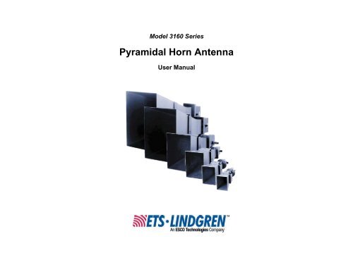
Model 3160 Series<br />
<strong>Pyramidal</strong> <strong>Horn</strong> <strong>Antenna</strong><br />
User Manual
<strong>ETS</strong>-<strong>Lindgren</strong> L.P. reserves the right to make changes to any product described<br />
herein in order to improve function, design, or for any other reason. Nothing<br />
contained herein shall constitute <strong>ETS</strong>-<strong>Lindgren</strong> L.P. assuming any liability<br />
whatsoever arising out of the application or use of any product or circuit<br />
described herein. <strong>ETS</strong>-<strong>Lindgren</strong> L.P. does not convey any license under its<br />
patent rights or the rights of others.<br />
© Copyright 1992–2011 by <strong>ETS</strong>-<strong>Lindgren</strong> L.P. All Rights Reserved. No part<br />
of this document may be copied by any means without written permission<br />
from <strong>ETS</strong>-<strong>Lindgren</strong> L.P.<br />
Trademarks used in this document: The <strong>ETS</strong>-<strong>Lindgren</strong> logo is a trademark of<br />
<strong>ETS</strong>-<strong>Lindgren</strong> L.P.<br />
Revision Record | MANUAL, 3160 SERIES | Part #399185, Rev. E<br />
Revision Description Date<br />
A Initial Release February, 1992<br />
B Edits/updates October, 2002<br />
C Edits/updates July, 2003<br />
D Rebrand July, 2010<br />
E Added 3160-u5 and 3160-u7<br />
ii |<br />
specifications<br />
November, 2011
Table of Contents<br />
Notes, Cautions, and Warnings .............................................. vii<br />
1.0 Introduction .......................................................................... 9<br />
Tripod Options .......................................................................................... 11<br />
<strong>ETS</strong>-<strong>Lindgren</strong> Product Information Bulletin ............................................... 12<br />
2.0 Maintenance ....................................................................... 13<br />
Annual Calibration .................................................................................... 13<br />
Service Procedures .................................................................................. 14<br />
3.0 Specifications ..................................................................... 15<br />
Electrical Specifications ............................................................................ 15<br />
Model 3160 Series ............................................................................ 15<br />
Model 3160-u5 and Model 3160-u7: Standard Gain <strong>Horn</strong>s<br />
Below 1 GHz ..................................................................................... 15<br />
Model 3160-u5 .......................................................................... 16<br />
Model 3160-u7 .......................................................................... 17<br />
Physical Specifications ............................................................................. 19<br />
Model 3160 Series ............................................................................ 19<br />
Model 3160-u5 and Model 3160-u7: Standard Gain <strong>Horn</strong>s<br />
Below 1 GHz ..................................................................................... 20<br />
Model 3160-u5 .......................................................................... 20<br />
Model 3160-u7 .......................................................................... 25<br />
4.0 Mounting Instructions ....................................................... 31<br />
3160-09 and 3160-10 Only ....................................................................... 32<br />
3160-09 ............................................................................................ 32<br />
3160-10 ............................................................................................ 32<br />
Mount to 4-TR ........................................................................................... 33<br />
Mount to 7-TR and Mast ........................................................................... 34<br />
Mount to 2x2 Boom ................................................................................... 35<br />
5.0 Typical Data ........................................................................ 37<br />
Typical VSWR (3160-06) .......................................................................... 37<br />
Typical Gain and <strong>Antenna</strong> Factor (3160-06) .............................................. 38<br />
Typical Half-Power Beamwidth (3160-06) ................................................. 39<br />
6.0 Radiated Emissions Measurements ................................ 41<br />
| iii
iv |<br />
Measure Ambient Field Strength Values ................................................... 41<br />
Conversion Formulas ................................................................................ 42<br />
Equation 1 ........................................................................................ 42<br />
Equation 2 ........................................................................................ 43<br />
Equation 3 ........................................................................................ 43<br />
Equation 4 ........................................................................................ 43<br />
Equation 5 ........................................................................................ 43<br />
Equation 6 ........................................................................................ 44<br />
Equation 7 ........................................................................................ 44<br />
Equation 8 ........................................................................................ 44<br />
Equation 9 ........................................................................................ 44<br />
Appendix A: Warranty ............................................................. 45<br />
Appendix B: Power Requirements ......................................... 47<br />
3160-01 .................................................................................................... 48<br />
Table 1: Model 3160-01 Power Requirements at 1 Meter .................. 48<br />
Table 2: Model 3160-01 Power Requirements at 3 and 10 Meters .... 48<br />
3160-02 .................................................................................................... 49<br />
Table 3: Model 3160-02 Power Requirements at 1 Meter .................. 49<br />
Table 4: Model 3160-02 Power Requirements at 3 and 10 Meters .... 49<br />
3160-03 .................................................................................................... 50<br />
Table 5: Model 3160-03 Power Requirements at 1 Meter .................. 50<br />
Table 6: Model 3160-03 Power Requirements at 3 and 10 Meters .... 50<br />
3160-04 .................................................................................................... 51<br />
Table 7: Model 3160-04 Power Requirements at 1 Meter .................. 51<br />
Table 8: Model 3160-04 Power Requirements at 3 and 10 Meters .... 51<br />
3160-05 .................................................................................................... 52<br />
Table 9: Model 3160-05 Power Requirements at 1 Meter .................. 52<br />
Table 10: Model 3160-05 Power Requirements at 3 and 10 Meters .. 52<br />
3160-06 .................................................................................................... 53<br />
Table 11: Model 3160-06 Power Requirements at 1 Meter ................ 53<br />
Table 12: Model 3160-06 Power Requirements at 3 and 10 Meters .. 53<br />
3160-07 .................................................................................................... 54<br />
Table 13: Model 3160-07 Power Requirements at 1 Meter ................ 54<br />
Table 14: Model 3160-07 Power Requirements at 3 and 10 Meters .. 54<br />
3160-08 .................................................................................................... 55<br />
Table 15: Model 3160-08 Power Requirements at 1 Meter ................ 55
Table 16: Model 3160-08 Power Requirements at 3 and 10 Meters .. 55<br />
3160-09 .................................................................................................... 56<br />
Table 17: Model 3160-09 Power Requirements at 1 Meter ................ 56<br />
Table 18: Model 3160-09 Power Requirements at 3 and 10 Meters .. 56<br />
3160-10 .................................................................................................... 57<br />
Table 19: Model 3160-10 Power Requirements at 1 Meter ................ 57<br />
Table 20: Model 3160-10 Power Requirements at 3 and 10 Meters .. 57<br />
Appendix C: Model 3160 Series Data ..................................... 59<br />
3160-01 .................................................................................................... 59<br />
VSWR: 3160-01 ................................................................................ 59<br />
Gain / <strong>Antenna</strong> Factor: 3160-01 ........................................................ 59<br />
Half-Power Beamwidth: 3160-01 ....................................................... 60<br />
<strong>Antenna</strong> Pattern: 3160-01 at 1.2 GHz ............................................... 61<br />
3160-02 .................................................................................................... 62<br />
VSWR: 3160-02 ................................................................................ 62<br />
Gain / <strong>Antenna</strong> Factor: 3160-02 ........................................................ 62<br />
Half-Power Beamwidth: 3160-02 ....................................................... 63<br />
<strong>Antenna</strong> Pattern: 3160-02 at 1.41 GHz ............................................. 64<br />
3160-03 .................................................................................................... 65<br />
VSWR: 3160-03 ................................................................................ 65<br />
Gain / <strong>Antenna</strong> Factor: 3160-03 ........................................................ 65<br />
Half-Power Beamwidth: 3160-03 ....................................................... 66<br />
<strong>Antenna</strong> Pattern: 3160-03 at 2.15 GHz ............................................. 67<br />
3160-04 .................................................................................................... 68<br />
VSWR: 3160-04 ................................................................................ 68<br />
Gain / <strong>Antenna</strong> Factor: 3160-04 ........................................................ 68<br />
Half-Power Beamwidth: 3160-04 ....................................................... 69<br />
<strong>Antenna</strong> Pattern: 3160-04 at 3.3 GHz ............................................... 70<br />
3160-05 .................................................................................................... 71<br />
VSWR: 3160-05 ................................................................................ 71<br />
Gain / <strong>Antenna</strong> Factor: 3160-05 ........................................................ 71<br />
Half-Power Beamwidth: 3160-05 ....................................................... 72<br />
<strong>Antenna</strong> Pattern: 3160-05 at 4.9 GHz ............................................... 73<br />
3160-06 .................................................................................................... 74<br />
VSWR: 3160-06 ................................................................................ 74<br />
Gain / <strong>Antenna</strong> Factor: 3160-06 ........................................................ 74<br />
| v
vi |<br />
Half-Power Beamwidth: 3160-06 ....................................................... 75<br />
<strong>Antenna</strong> Pattern: 3160-06 at 7.0 GHz ............................................... 76<br />
3160-07 .................................................................................................... 77<br />
VSWR: 3160-07 ................................................................................ 77<br />
Gain / <strong>Antenna</strong> Factor: 3160-07 ........................................................ 77<br />
Half-Power Beamwidth: 3160-07 ....................................................... 78<br />
<strong>Antenna</strong> Pattern: 3160-07 at 10.3 GHz ............................................. 79<br />
3160-08 .................................................................................................... 80<br />
VSWR: 3160-08 ................................................................................ 80<br />
Gain / <strong>Antenna</strong> Factor: 3160-08 ........................................................ 80<br />
Half-Power Beamwidth: 3160-08 ....................................................... 81<br />
<strong>Antenna</strong> Pattern: 3160-08 at 15.2 GHz ............................................. 82<br />
3160-09 .................................................................................................... 83<br />
VSWR: 3160-09 ................................................................................ 83<br />
Gain / <strong>Antenna</strong> Factor: 3160-09 ........................................................ 83<br />
Half-Power Beamwidth: 3160-09 ....................................................... 84<br />
<strong>Antenna</strong> Pattern: 3160-09 at 22.0 GHz ............................................. 85<br />
3160-10 .................................................................................................... 86<br />
VSWR: 3160-10 ................................................................................ 86<br />
Gain / <strong>Antenna</strong> Factor: 3160-10 ........................................................ 86<br />
Half-Power Beamwidth: 3160-10 ....................................................... 87<br />
<strong>Antenna</strong> Pattern: 3160-10 at 33.0 GHz ............................................. 88
Notes, Cautions, and Warnings<br />
Note: Denotes helpful information intended to<br />
provide tips for better use of the product.<br />
Caution: Denotes a hazard. Failure to follow<br />
instructions could result in minor personal injury<br />
and/or property damage. Included text gives proper<br />
procedures.<br />
Warning: Denotes a hazard. Failure to follow<br />
instructions could result in SEVERE personal injury<br />
and/or property damage. Included text gives proper<br />
procedures.<br />
See the <strong>ETS</strong>-<strong>Lindgren</strong> Product Information Bulletin for safety,<br />
regulatory, and other product marking information.<br />
| vii
This page intentionally left blank.<br />
viii |
1.0 Introduction<br />
The <strong>ETS</strong>-<strong>Lindgren</strong> Model 3160 Series <strong>Pyramidal</strong> <strong>Horn</strong> <strong>Antenna</strong> is a series of<br />
pyramidal standard gain horn antennas designed specifically for utilization in<br />
emissions and immunity testing over the frequency range of 1 GHz to 40 GHz.<br />
The Model 3160 Series includes models 3160-01 through 3160-10.<br />
Each Model 3160 Series antenna is linearly polarized and has medium gain,<br />
wide half-power beamwidth (HPBW) in both the horizontal and vertical planes,<br />
low VSWR over the recommended operating frequency range, and constant<br />
antenna factors so that the antennas can be used without looking up tables or<br />
charts.<br />
The performance of the Model 3160 Series is precise and predictable through<br />
design parameters. Both input and output are well matched to 50 Ω and 377 Ω<br />
respectively. Comparisons of measured versus computed gain and antenna<br />
factors have been found to be within ±0.5dB. The Model 3160 Series antennas<br />
are considered to be the standard reference of measurements above 1 GHz, as<br />
is the resonant dipole for measurements below 1 GHz.<br />
Each Model 3160 Series antenna is ruggedly constructed for good<br />
electromagnetic performance.<br />
Models 3160-01 through 3160-06 are welded using precise toolings<br />
and aluminum sheet metal.<br />
Models 3160-07 and 3160-08 are investment casted using an<br />
aluminum compound.<br />
Models 3160-09 and 3160-10 are electroformed using deposition of<br />
copper at a rate of 0.001 inch/hour for the highest precision available.<br />
Models 3160-01 through 3160-08 are conversion coated and painted<br />
for protection against corrosion and changes in the weather.<br />
Each Model 3160 Series antenna comes completely assembled with a<br />
high performance, low VSWR, coax-to-waveguide adapter. Below 18 GHz, the<br />
transition from coax to waveguide is made using a female Precision N connector.<br />
Above 18 GHz, the transition uses female K connectors. The coax-to-waveguide<br />
adapters are the only power-limiting component, and can be removed if<br />
high fields are desired. For this purpose, the RF generator must be equipped with<br />
waveguide ports. In such a configuration, fields in excess of 10,000 V/m at<br />
10 meters can be obtained.<br />
Introduction | 9
Each Model 3160 Series antenna comes with a standard 1/4–20 mount.<br />
Horizontal and vertical polarizations are obtained by rotating the antennas from<br />
one position on the mount to the other. The mounts have been placed so as not<br />
to interfere with incoming electromagnetic energy. For the variety of mounting<br />
options available for the Model 3160 Series, see Mounting Instructions on<br />
page 20.<br />
The Model 3160 Series may be used for either transmission or reception. The<br />
50 ohm input impedance is well-matched for generating high electric fields with<br />
little power reflected back to the amplifier, reducing the chance of saturation. As<br />
a receiver, the antennas are matched to free space (377 ohms). Typical<br />
performance data is provided beginning on page 37. Methods for radiated<br />
emissions measurement are described on page 41.<br />
For TEMPEST applications, all Model 3160 Series antennas, especially models<br />
3160-03 and up, can be mounted on standard 12-, 18-, or 24-inch reflector<br />
dishes. The resulting antenna factor is usually about 20 dB lower than that of the<br />
antennas by themselves. However, the HPBW drops to less than 50 and the<br />
far field distance increases drastically making near field performance less<br />
predictable.<br />
10 | Introduction
Tripod Options<br />
Do not mount the Model 3160-01 or<br />
Model 3160-02 to a 4-TR.<br />
<strong>ETS</strong>-<strong>Lindgren</strong> offers the following non-metallic, non-reflective tripods for use at<br />
both indoor and outdoor EMC test sites.<br />
4-TR Tripod—Constructed of linen<br />
phenolic and delrin, designed with an<br />
adjustable center post for precise height<br />
adjustments. Maximum height is 2.0 m<br />
(80.0 in), and minimum height is 94 cm<br />
(37.0 in). This tripod can support up to<br />
an 11.8 kg (26.0 lb) load.<br />
7-TR Tripod—Constructed of PVC and<br />
fiberglass components, providing<br />
increased stability for physically large<br />
antennas. The unique design allows for<br />
quick assembly, disassembly, and<br />
convenient storage. Allows several<br />
different configurations, including options<br />
for manual or pneumatic polarization.<br />
Quick height adjustment and locking<br />
wheels provide ease of use during<br />
testing. Maximum height is 2.17 m<br />
(85.8 in), with a minimum height of 0.8 m<br />
(31.8 in). This tripod can support a<br />
13.5 kg (30 lb) load.<br />
Introduction | 11
<strong>ETS</strong>-<strong>Lindgren</strong> Product Information Bulletin<br />
See the <strong>ETS</strong>-<strong>Lindgren</strong> Product Information Bulletin included with your shipment<br />
for the following:<br />
Warranty information<br />
Safety, regulatory, and other product marking information<br />
Steps to receive your shipment<br />
Steps to return a component for service<br />
<strong>ETS</strong>-<strong>Lindgren</strong> calibration service<br />
<strong>ETS</strong>-<strong>Lindgren</strong> contact information<br />
12 | Introduction
2.0 Maintenance<br />
Before performing any maintenance,<br />
follow the safety information in the<br />
<strong>ETS</strong>-<strong>Lindgren</strong> Product Information<br />
Bulletin included with your shipment.<br />
Maintenance of the Model 3160 Series is<br />
limited to external components such as<br />
cables or connectors.<br />
If you have any questions concerning<br />
maintenance, contact <strong>ETS</strong>-<strong>Lindgren</strong><br />
Customer Service.<br />
When not in use, the Model 3160 Series <strong>Pyramidal</strong> <strong>Horn</strong> <strong>Antenna</strong><br />
should be stored on a shelf face down to keep dust out of the feed<br />
areas.<br />
WARRANTY<br />
If the Model 3160 Series is used outdoors, the antennas should be<br />
checked for water accumulations. Water has a high dielectric constant<br />
and can alter performance.<br />
If an antenna is dropped, the feed/horn joint should be checked for<br />
misalignment.<br />
Annual Calibration<br />
The electromagnetic performance of the Model 3160 Series is almost exclusively<br />
dependent on the physical dimensions of the horns. Comparisons with<br />
computed gain and antenna factor result in differences within 1 dB. Therefore, it<br />
is not necessary to calibrate Model 3160 Series antennas; only a mechanical<br />
check is required to guarantee performance. However, if calibration is required,<br />
see the Product Information Bulletin included with your shipment for information<br />
on <strong>ETS</strong>-<strong>Lindgren</strong> calibration services.<br />
Maintenance | 13
Service Procedures<br />
For the steps to return a system or system component to <strong>ETS</strong>-<strong>Lindgren</strong> for<br />
service, see the Product Information Bulletin included with your shipment.<br />
14 | Maintenance
3.0 Specifications<br />
Electrical Specifications<br />
MODEL 3160 SERIES<br />
The VSWR indicated in the following table is that of the pyramidal horn<br />
antenna and coax-to-waveguide adapter. The VSWR of the antenna by<br />
itself is of the order of 1.1:1.<br />
The maximum continuous power indicated in the following table is<br />
mainly limited by the coax-to-waveguide adapter. The antenna itself is<br />
capable of handling continuous power on the order of 10 4 Watts to<br />
10 7 Watts.<br />
MODEL 3160-U5 AND MODEL 3160-U7: STANDARD GAIN HORNS<br />
BELOW 1 GHZ<br />
<strong>ETS</strong>-<strong>Lindgren</strong> also offers these two standard gain horns:<br />
Model 3160-u5—Operates from 500 MHz to 750 MHz.<br />
Model 3160-u7—Operates from 750 MHz to 1 GHz.<br />
These horns require customized mounts due to their large physical size; for more<br />
information see the Model 3160-u5 and Model 3160-u7 drawings provided in<br />
Physical Specifications beginning on page 20.<br />
The following sections provide the computed gain for the Model 3160-u5 and<br />
Model 3160-u7.<br />
Specifications | 15
MODEL 3160-U5<br />
Far field gain computed using full wave analysis MW Studio.<br />
Frequency (MHz) Computed Gain (dBi) Numeric Gain VSWR<br />
500 16.42 43.87 1.48<br />
510 16.76 47.37 1.43<br />
520 16.95 49.52 1.35<br />
530 17.02 50.40 1.24<br />
540 17.06 50.80 1.13<br />
550 17.11 51.44 1.07<br />
560 17.21 52.56 1.12<br />
570 17.32 53.93 1.17<br />
580 17.42 55.19 1.17<br />
590 17.50 56.25 1.13<br />
600 17.58 57.30 1.07<br />
610 17.68 58.55 1.06<br />
620 17.78 60.01 1.13<br />
630 17.88 61.44 1.18<br />
640 17.96 62.55 1.18<br />
650 18.02 63.37 1.16<br />
670 18.18 65.80 1.10<br />
680 18.33 68.09 1.08<br />
690 18.50 70.79 1.09<br />
16 | Specifications
Frequency (MHz) Computed Gain (dBi) Numeric Gain VSWR<br />
700 18.64 73.11 1.13<br />
710 18.71 74.30 1.16<br />
720 18.70 74.13 1.16<br />
760 18.65 73.22 1.14<br />
740 18.53 71.30 1.12<br />
750 18.50 70.86 1.10<br />
MODEL 3160-U7<br />
Far field gain computed using full wave analysis MW Studio.<br />
Frequency (MHz) Computed Gain (dBi) Numeric Gain VSWR<br />
750 14.64 29.09 1.35<br />
760 14.77 29.99 1.33<br />
770 14.90 30.91 1.34<br />
780 15.03 31.84 1.38<br />
790 15.15 32.77 1.41<br />
800 15.26 33.60 1.42<br />
810 15.35 34.27 1.38<br />
820 15.41 34.77 1.31<br />
830 15.46 35.17 1.21<br />
840 15.51 35.57 1.11<br />
850 15.57 36.07 1.07<br />
Specifications | 17
Frequency (MHz) Computed Gain (dBi) Numeric Gain VSWR<br />
860 15.64 36.67 1.11<br />
870 15.73 37.39 1.16<br />
890 15.93 39.14 1.19<br />
900 16.04 40.15 1.18<br />
910 16.15 41.24 1.16<br />
920 16.27 42.35 1.12<br />
930 16.38 43.45 1.09<br />
940 16.49 44.53 1.08<br />
950 16.59 45.56 1.11<br />
960 16.68 46.51 1.16<br />
970 16.76 47.37 1.22<br />
980 16.82 48.12 1.26<br />
990 16.88 48.76 1.28<br />
1000 16.93 49.37 1.27<br />
18 | Specifications
Physical Specifications<br />
MODEL 3160 SERIES<br />
Specifications | 19
MODEL 3160-U5 AND MODEL 3160-U7: STANDARD GAIN HORNS<br />
BELOW 1 GHZ<br />
MODEL 3160-U5<br />
Weight (approximate): 95.3 kg (210.0 lb)<br />
Two mounting subframes with hardware are provided with the<br />
Model 3160-u5. Hardware for customer mount is not provided.<br />
20 | Specifications
Model 3160-u5 Aperture View<br />
Specifications | 21
Model 3160-u5 Side View<br />
22 | Specifications
Model 3160-u5 Back View<br />
Specifications | 23
Model 3160-u5 Bottom View<br />
Clearance holes (7) in bottom of subframe are for M8 or 3/8–16 bolts.<br />
Hardware not provided.<br />
24 | Specifications
MODEL 3160-U7<br />
Weight (approximate): 32.7 kg (72.0 lb)<br />
Two mounting platforms are provided with the Model 3160-u7.<br />
Mounting fasteners (1/4–20) are not provided.<br />
Specifications | 25
Model 3160-u7 Aperture View<br />
26 | Specifications
Model 3160-u7 Side View<br />
Specifications | 27
Model 3160-u7 Back View<br />
28 | Specifications
Model 3160-u7 Bottom View<br />
Specifications | 29
This page intentionally left blank.<br />
30 | Specifications
4.0 Mounting Instructions<br />
Before connecting any components, follow the<br />
safety information in the <strong>ETS</strong>-<strong>Lindgren</strong><br />
Product Information Bulletin included with your<br />
shipment.<br />
The Model 3160 Series antennas are precision<br />
measurement devices. Handle your antenna<br />
with care.<br />
Horizontal and vertical polarizations can be achieved by rotating the<br />
antenna from one mount to the other.<br />
The Model 3160-u5 and Model 3160-u7 horns require customized<br />
mounts due to their large physical size; for more information see the<br />
Model 3160-u5 and Model 3160-u7 drawings provided in Physical<br />
Specifications beginning on page 20.<br />
The Model 3160 Series <strong>Pyramidal</strong> <strong>Horn</strong> <strong>Antenna</strong> is equipped with a standard<br />
1/4–20 mount. The mount is placed so as not to interfere with incoming<br />
electromagnetic energy.<br />
Once mounted, remove the red cover from the Type N connector and attach a<br />
cable between the antenna and a transmitting/receiving RF device. Rotate the<br />
antenna for horizontal and vertical polarizations as needed.<br />
Mounting Instructions | 31
3160-09 and 3160-10 Only<br />
The 3160-09 and 3160-10 antennas ship with a supplemental mount that may be<br />
used with the 4-TR Tripod, 7-TR Tripod, mast, and 2x2 boom.<br />
3160-09<br />
3160-10<br />
103255 Clamping Block<br />
103256 Mounting Bracket<br />
103253 Clamping Block<br />
103254 Mounting Bracket<br />
32 | Mounting Instructions
Mount to 4-TR<br />
Do not mount the Model 3160-01 or<br />
Model 3160-02 to a 4-TR.<br />
Model 3160 Series antennas mount directly to an <strong>ETS</strong>-<strong>Lindgren</strong> 4-TR Tripod; no<br />
additional hardware is required. Secure the mount onto the 4-TR by tightening<br />
the1/4–20 UNC mount knob.<br />
Mounting Instructions | 33
Mount to 7-TR and Mast<br />
Following is an option for mounting the Model 3160 Series onto an <strong>ETS</strong>-<strong>Lindgren</strong><br />
7-TR Tripod or mast. Contact the <strong>ETS</strong>-<strong>Lindgren</strong> Sales Department for<br />
information on ordering optional mounting hardware.<br />
Mast refers to 2070 Series, 2075,<br />
and 2175 <strong>Antenna</strong> Towers.<br />
7-TR refers to 109042, 108983, and<br />
108197 booms:<br />
109042 boom—Straight boom;<br />
for general antenna mounting<br />
on a 7-TR<br />
108983 boom—Offset boom;<br />
for general antenna mounting<br />
on a 7-TR with pneumatic or<br />
manual polarization; can also<br />
be used to mount stinger-type<br />
antennas<br />
108197 boom—Center rotate<br />
boom; stinger-type antennas<br />
only<br />
34 | Mounting Instructions
Mount to 2x2 Boom<br />
Following are options for mounting the Model 3160 Series onto a 2x2 boom.<br />
Contact the <strong>ETS</strong>-<strong>Lindgren</strong> Sales Department for information on ordering optional<br />
mounting hardware.<br />
2x2 boom refers to a typical 2-inch by 2-inch boom.<br />
Mounting Instructions | 35
This page intentionally left blank.<br />
36 | Mounting Instructions
5.0 Typical Data<br />
Following is typical electromagnetic performance data for the Model 3160 Series<br />
<strong>Pyramidal</strong> <strong>Horn</strong> <strong>Antenna</strong>, using Model 3160-06 data as representative of the<br />
series. See Model 3160 Series Data on page 59 for data for all<br />
Model 3160 Series antennas.<br />
Typical VSWR (3160-06)<br />
The following shows the antenna/coax-to-waveguide adapter assembly.<br />
Typical Data | 37
Typical Gain and <strong>Antenna</strong> Factor (3160-06)<br />
Following is a plot of computed and measured gain and antenna factor versus<br />
frequency. The measured and computed results are within 3 dB, which is typical<br />
of pyramidal horns. Differences are attributed to imperfections in the<br />
measurements setup. The left vertical scale is for the gain measured in dBi, and<br />
the right vertical scale is for the antenna factor in dB(m -1 ). The antenna factor<br />
spans only 0.6 dB from minimum to maximum; therefore, it may be considered<br />
constant over the entire frequency band without loss of accuracy. The gain is<br />
computed from the antenna factor using:<br />
G(dB) = 20 log (f ) - AF + 30.22<br />
GHz dB(m -1 )<br />
38 | Typical Data
Typical Half-Power Beamwidth (3160-06)<br />
Following is a plot of the half-power beamwidth (HPBW) versus frequency. The<br />
information provides the size of the Equipment Under Test (EUT) that can be<br />
illuminated without scanning. The size of the EUT can be obtained as:<br />
HPBW<br />
EUT = 2[ Distance · tan( ) ]<br />
Distance is the distance between the EUT and the aperture of the antenna<br />
Typical Data | 39<br />
2
This page intentionally left blank.<br />
40 | Typical Data
6.0 Radiated Emissions Measurements<br />
Measure Ambient Field Strength Values<br />
1. Install the antenna where measured field strength values are desired.<br />
2. Adjust the desired orientation of the antenna for both bore site direction<br />
and polarization.<br />
3. Connect the output connector of the antenna to the input of the<br />
receiving system using a low VSWR, low loss coaxial cable. The<br />
Model 3160 Series <strong>Pyramidal</strong> <strong>Horn</strong> <strong>Antenna</strong>s are designed for<br />
receiving systems having 50 Ω input impedance. Other values of<br />
receiving system input impedance will require correction for the<br />
difference in impedance mismatch.<br />
4. Set desired measurement frequency on the receiving system. Make<br />
sure that the selected frequency is one that can be used with the<br />
antenna that is connected to the system.<br />
5. Measure the RF voltage, Va, referenced to the input port of the<br />
receiving system. The units of the measurement should be in decibels<br />
referenced to 1 microvolt, dB(µV). If the units of measurements are<br />
millivolts, they should be converted to dB(µV) by:<br />
V 20 log ( RF voltage in microvolts )<br />
a<br />
10<br />
V 20 log<br />
V<br />
a 10 d<br />
6. Determine the field strength at the frequency of observation by adding<br />
the voltage reading on the receiving system in dB(µV) to the<br />
antenna factor in dB(m -1 ):<br />
RF Voltage, dB(µV) + <strong>Antenna</strong> Factor, dB(m -1 ) =<br />
Field Strength, dB(µV/m)<br />
Ea = Va + AF<br />
Radiated Emissions Measurements | 41
The losses of the coaxial cable, Ac , should be included in the<br />
computations. In this case, the previous equation becomes:<br />
RF Voltage, dB(µV) + Cable Loss, dB +<br />
<strong>Antenna</strong> Factor, DB(m -1 ) = Field Strength, dB(µV/m)<br />
Conversion Formulas<br />
Ea = Va + Ac + AF<br />
Following are some useful conversion formulas, including how the constants are<br />
obtained:<br />
EQUATION 1<br />
dBm=dB(V)-107<br />
The power is related to the voltage and the system impedance as:<br />
P V<br />
2<br />
<br />
R<br />
In a 50 Ω system, the previous equation becomes:<br />
10log P 20log V 10log ( 50)<br />
10 10 10<br />
Converting from dB to dBm for power and from dB(V) to dB(µV) for<br />
voltage, the overall constant becomes:<br />
30 12010log ( 50) 107<br />
42 | Radiated Emissions Measurements<br />
10
EQUATION 2<br />
EQUATION 3<br />
EQUATION 4<br />
EQUATION 5<br />
dB(mW /m 2 ) = dB(V/m)-115.8<br />
The constant in this equation is obtained by considering the<br />
Poynting vector which relates the power density in (W/m 2 ) to the<br />
electric field strength in (V/m) by:<br />
Where η is the free space characteristic impedance equal to 120π Ω.<br />
Transforming the previous questions to decibels and using the<br />
appropriate conversion factors to convert dB(W/m 2 ) to dB(mW/m 2 ) for<br />
power density and dB(V/m) to dB(µV/m) for the electric field, the<br />
constant becomes:<br />
30 120 10log ( 120 ) 115.<br />
8<br />
10<br />
dB(V/m) = dB(V) + AF<br />
V/m = 10<br />
dB ( V/m)-120<br />
20<br />
P =<br />
E 2<br />
<br />
dB (A/m) = dB(V/m) - 51.5<br />
The magnetic field strength is related to the electric field strength via<br />
the characteristic impedance of free space. When the transformation is<br />
made to decibels, the constant becomes:<br />
20log ( 120) 51.<br />
5<br />
10<br />
Radiated Emissions Measurements | 43
EQUATION 6<br />
EQUATION 7<br />
EQUATION 8<br />
EQUATION 9<br />
A/m = 10<br />
dB ( A/m)-120<br />
20<br />
dB(W/m 2 ) = 10 log (V/m A/m)<br />
dB(mW/m 2 ) = dB(W/m 2 ) + 30.0<br />
dB(pT) = dB(A/m) + 2.0<br />
The magnetic flux density B in (T) is related to the magnetic field<br />
strength H in (A/m) by the permeability of the medium in (H/m). For<br />
free space, the permeability is µo = 4π.10 -7 H/m. Converting from (T)<br />
to (pT) and from (A/m) to (µA/m) and taking the log, the constant<br />
becomes:<br />
7<br />
240 120 20log ( 4 10 ) 2.<br />
0<br />
44 | Radiated Emissions Measurements<br />
10
Appendix A: Warranty<br />
See the Product Information Bulletin included with your shipment for<br />
the complete <strong>ETS</strong>-<strong>Lindgren</strong> warranty for your Model 3160 Series.<br />
DURATION OF WARRANTIES FOR MODEL 3160 SERIES<br />
All product warranties, except the warranty of title, and all remedies for warranty<br />
failures are limited to two years.<br />
Product Warranted Duration of Warranty Period<br />
Model 3160 Series<br />
<strong>Pyramidal</strong> <strong>Horn</strong> <strong>Antenna</strong><br />
2 Years<br />
Warranty | 45
This page intentionally left blank.<br />
46 | Warranty
Appendix B: Power Requirements<br />
The Model 3160 Series <strong>Pyramidal</strong> <strong>Horn</strong> <strong>Antenna</strong> is an efficient transmitting<br />
antenna, capable of generating high electric field strengths using little power. For<br />
a given electric field strength, the required power can be computed using the<br />
transmission equation:<br />
(Field Strength ) ( Distance in meters)<br />
Power Transmitted=<br />
(30 Numeric Gain )<br />
P<br />
The typical power requirements in Watts for the 3161-06 are shown in Table 11<br />
Table 12 on page 53. Distance is measured from the aperture of the antenna.<br />
The maximum continuous power that can be applied is 250 W, and the maximum<br />
peak power is 8 kW. For example, to generate an electric field equal to 100 V/m<br />
at a distance of 3 meters at a frequency of 6.25 GHz, the calibration antenna<br />
factor read from Table 1 is 29.9 dB(m -1 ). The gain in dB is computed using:<br />
G(dB)=20 log(FGHz ) – AF + 30.22<br />
G(dB)=20 log(6.25) – 29.9 + 30.22 = 16.2<br />
The numeric gain is obtained as:<br />
g = 10 1.62 = 42.1<br />
Applying this equation, we obtain:<br />
t<br />
2<br />
E R<br />
<br />
30<br />
g<br />
2<br />
2 2<br />
Power Requirements | 47
3160-01<br />
TABLE 1: MODEL 3160-01 POWER REQUIREMENTS AT 1 METER<br />
TABLE 2: MODEL 3160-01 POWER REQUIREMENTS AT 3 AND 10 METERS<br />
48 | Power Requirements
3160-02<br />
TABLE 3: MODEL 3160-02 POWER REQUIREMENTS AT 1 METER<br />
TABLE 4: MODEL 3160-02 POWER REQUIREMENTS AT 3 AND 10 METERS<br />
Power Requirements | 49
3160-03<br />
TABLE 5: MODEL 3160-03 POWER REQUIREMENTS AT 1 METER<br />
TABLE 6: MODEL 3160-03 POWER REQUIREMENTS AT 3 AND 10 METERS<br />
50 | Power Requirements
3160-04<br />
TABLE 7: MODEL 3160-04 POWER REQUIREMENTS AT 1 METER<br />
TABLE 8: MODEL 3160-04 POWER REQUIREMENTS AT 3 AND 10 METERS<br />
Power Requirements | 51
3160-05<br />
TABLE 9: MODEL 3160-05 POWER REQUIREMENTS AT 1 METER<br />
TABLE 10: MODEL 3160-05 POWER REQUIREMENTS AT 3 AND<br />
10 METERS<br />
52 | Power Requirements
3160-06<br />
TABLE 11: MODEL 3160-06 POWER REQUIREMENTS AT 1 METER<br />
TABLE 12: MODEL 3160-06 POWER REQUIREMENTS AT 3 AND<br />
10 METERS<br />
Power Requirements | 53
3160-07<br />
TABLE 13: MODEL 3160-07 POWER REQUIREMENTS AT 1 METER<br />
TABLE 14: MODEL 3160-07 POWER REQUIREMENTS AT 3 AND<br />
10 METERS<br />
54 | Power Requirements
3160-08<br />
TABLE 15: MODEL 3160-08 POWER REQUIREMENTS AT 1 METER<br />
TABLE 16: MODEL 3160-08 POWER REQUIREMENTS AT 3 AND<br />
10 METERS<br />
Power Requirements | 55
3160-09<br />
TABLE 17: MODEL 3160-09 POWER REQUIREMENTS AT 1 METER<br />
TABLE 18: MODEL 3160-09 POWER REQUIREMENTS AT 3 AND<br />
10 METERS<br />
56 | Power Requirements
3160-10<br />
TABLE 19: MODEL 3160-10 POWER REQUIREMENTS AT 1 METER<br />
TABLE 20: MODEL 3160-10 POWER REQUIREMENTS AT 3 AND<br />
10 METERS<br />
Power Requirements | 57
This page intentionally left blank.<br />
58 | Power Requirements
Appendix C: Model 3160 Series Data<br />
3160-01<br />
VSWR: 3160-01<br />
GAIN / ANTENNA FACTOR: 3160-01<br />
Model 3160 Series Data | 59
HALF-POWER BEAMWIDTH: 3160-01<br />
60 | Model 3160 Series Data
ANTENNA PATTERN: 3160-01 AT 1.2 GHZ<br />
H-PLANE: 3160-01<br />
E-PLANE: 3160-01<br />
Model 3160 Series Data | 61
3160-02<br />
VSWR: 3160-02<br />
GAIN / ANTENNA FACTOR: 3160-02<br />
62 | Model 3160 Series Data
HALF-POWER BEAMWIDTH: 3160-02<br />
Model 3160 Series Data | 63
ANTENNA PATTERN: 3160-02 AT 1.41 GHZ<br />
H-PLANE: 3160-02<br />
E-PLANE: 3160-02<br />
64 | Model 3160 Series Data
3160-03<br />
VSWR: 3160-03<br />
GAIN / ANTENNA FACTOR: 3160-03<br />
Model 3160 Series Data | 65
HALF-POWER BEAMWIDTH: 3160-03<br />
66 | Model 3160 Series Data
ANTENNA PATTERN: 3160-03 AT 2.15 GHZ<br />
H-PLANE: 3160-03<br />
E-PLANE: 3160-03<br />
Model 3160 Series Data | 67
3160-04<br />
VSWR: 3160-04<br />
GAIN / ANTENNA FACTOR: 3160-04<br />
68 | Model 3160 Series Data
HALF-POWER BEAMWIDTH: 3160-04<br />
Model 3160 Series Data | 69
ANTENNA PATTERN: 3160-04 AT 3.3 GHZ<br />
H-PLANE: 3160-04<br />
E-PLANE: 3160-04<br />
70 | Model 3160 Series Data
3160-05<br />
VSWR: 3160-05<br />
GAIN / ANTENNA FACTOR: 3160-05<br />
Model 3160 Series Data | 71
HALF-POWER BEAMWIDTH: 3160-05<br />
72 | Model 3160 Series Data
ANTENNA PATTERN: 3160-05 AT 4.9 GHZ<br />
H-PLANE: 3160-05<br />
E-PLANE: 3160-05<br />
Model 3160 Series Data | 73
3160-06<br />
VSWR: 3160-06<br />
GAIN / ANTENNA FACTOR: 3160-06<br />
74 | Model 3160 Series Data
HALF-POWER BEAMWIDTH: 3160-06<br />
Model 3160 Series Data | 75
ANTENNA PATTERN: 3160-06 AT 7.0 GHZ<br />
H-PLANE: 3160-06<br />
E-PLANE: 3160-06<br />
76 | Model 3160 Series Data
3160-07<br />
VSWR: 3160-07<br />
GAIN / ANTENNA FACTOR: 3160-07<br />
Model 3160 Series Data | 77
HALF-POWER BEAMWIDTH: 3160-07<br />
78 | Model 3160 Series Data
ANTENNA PATTERN: 3160-07 AT 10.3 GHZ<br />
H-PLANE: 3160-07<br />
E-PLANE: 3160-07<br />
Model 3160 Series Data | 79
3160-08<br />
VSWR: 3160-08<br />
GAIN / ANTENNA FACTOR: 3160-08<br />
80 | Model 3160 Series Data
HALF-POWER BEAMWIDTH: 3160-08<br />
Model 3160 Series Data | 81
ANTENNA PATTERN: 3160-08 AT 15.2 GHZ<br />
H-PLANE: 3160-08<br />
E-PLANE: 3160-08<br />
82 | Model 3160 Series Data
3160-09<br />
VSWR: 3160-09<br />
GAIN / ANTENNA FACTOR: 3160-09<br />
Model 3160 Series Data | 83
HALF-POWER BEAMWIDTH: 3160-09<br />
84 | Model 3160 Series Data
ANTENNA PATTERN: 3160-09 AT 22.0 GHZ<br />
H-PLANE: 3160-09<br />
E-PLANE: 3160-09<br />
Model 3160 Series Data | 85
3160-10<br />
VSWR: 3160-10<br />
GAIN / ANTENNA FACTOR: 3160-10<br />
86 | Model 3160 Series Data
HALF-POWER BEAMWIDTH: 3160-10<br />
Model 3160 Series Data | 87
ANTENNA PATTERN: 3160-10 AT 33.0 GHZ<br />
H-PLANE: 3160-10<br />
E-PLANE: 3160-10<br />
88 | Model 3160 Series Data