Vacuum Melting and Remelting Processes - ASM International
Vacuum Melting and Remelting Processes - ASM International
Vacuum Melting and Remelting Processes - ASM International

Create successful ePaper yourself
Turn your PDF publications into a flip-book with our unique Google optimized e-Paper software.
<strong>ASM</strong> H<strong>and</strong>book Volume 15: Casting (#05115G)<br />
408 / Foundry Equipment <strong>and</strong> Processing<br />
<strong>Remelting</strong> Variations<br />
Under <strong>Vacuum</strong><br />
Apart from the remelting of a consumable<br />
electrode in a water-cooled copper crucible,<br />
there is a recent development of the vacuum<br />
arc remelting process, namely vacuum arc<br />
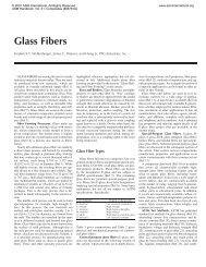
double electrode remelting (VADER). Fig-<br />
ure 5 shows the basic design of the VADER<br />
process with a static crucible. The arc is<br />
struck between the two horizontal elec-<br />
trodes that are to be melted.<br />
As in vacuum arc remelting, the metal<br />
drops fall into a water-cooled copper mold.<br />
Bath temperature, <strong>and</strong> therefore pool<br />
depth, can be very closely controlled. Re-<br />
melting can be done with minimal super-<br />
heating; segregation is thus minimized. The<br />
advantages of the VADER process over<br />
vacuum arc remelting are as follows (Ref<br />
10):<br />
• Very low or no superheating of the pool<br />
<strong>and</strong> high rate of nucleation, producing a<br />
fine grain structure<br />
• The lowest possible influence of magnetic<br />
fields on melting bath movement<br />
• No condensation formation due to evap-<br />
oration of liquid elements on the crucible<br />
walls<br />
• Lower specific energy consumption<br />
• Good ultrasonic testability due to the fine<br />
macrostructure of the ingot<br />
REFERENCES<br />
l. W.A. Tiller <strong>and</strong> J.W. Rutter, Can. J.<br />
Phys., Vol 311, 1956, p 96<br />
2. W.H. Sutton, in Proceedings of the<br />
Seventh <strong>International</strong> <strong>Vacuum</strong> Metal-<br />
lurgy Conference (Tokyo), The Iron<br />
<strong>and</strong> Steel Institute of Japan, 1982, p<br />
904-915<br />
3. J. Preston, in Transactions of the Vac-<br />
uum Metallurgy Conference, American<br />
<strong>Vacuum</strong> Society, 1965, p 366-379<br />
4. A.S. Ballentyne <strong>and</strong> A. Mitchell, Iron-<br />
making Steelmaking, Vol 4, 1977, p<br />
222-238<br />
5. S. Sawa et al., in Proceedings of the<br />
Fourth <strong>International</strong> <strong>Vacuum</strong> Metal-<br />
lurgy Conference (Tokyo), The Iron<br />
<strong>and</strong> Steel Institute of Japan, 1974, p<br />
129-134<br />
6. J.W. Troutman, in Transactions of the<br />
<strong>Vacuum</strong> Metallurgy Conference, Amer-<br />
ican <strong>Vacuum</strong> Society, 1968, p 599-613<br />
7. R. Schlatter, Giesserei, Vol 61, 1970, p<br />
75-85<br />
8. A. Mitchell, in Proceedings of the Vac-<br />
uum Metallurgy Conference, Pitts-<br />
burgh, PA, 1986, p 55-61<br />
9. F.J. Wadier, in Proceedings of the Vac-<br />
Motor<br />
zl<br />
Digital sensors ~'1<br />
Digital controls ~ I<br />
Motor current<br />
control<br />
I" I<br />
Weight Electronics<br />
J<br />
t<br />
l-~ current Highcontrol<br />
lace<br />
Fig, 4 Schematic of automatic melt control system<br />
Fig, 5 Schematic of the VADER process<br />
Process<br />
line control<br />
1<br />
Installation<br />
graphics<br />
/ooooo/<br />
SoP(keys<br />
Electrode<br />
CPU<br />
Man ~-"] Auto<br />
. Analog in/out<br />
I--<br />
uum Metallurgy Conference, Pitts-<br />
burgh, PA, 1984, p 119-128<br />
10. J.W. Pridgeon, F.M. Darmava, J.S.<br />
Process<br />
graphics<br />
~6<br />
60<br />
6~<br />
60<br />
66<br />
60<br />
6~<br />
6<br />
6<br />
o000<br />
Softkeys<br />
Electrode<br />
Copyright © 2008 <strong>ASM</strong> <strong>International</strong> ®<br />
All rights reserved.<br />
www.asminternational.org<br />
~1 Printer<br />
1 Alarms<br />
Uninterruptable<br />
power supply<br />
+<br />
T<br />
Printer<br />
Crucible<br />
-- ~Static mold<br />
Plotter [<br />
(option)<br />
Winchester<br />
Huntington, <strong>and</strong> W.H. Sutton, in Super-<br />
alloys Source Book, American Society<br />
for Metals, 1984
<strong>ASM</strong> H<strong>and</strong>book Volume 15: Casting (#05115G)<br />
<strong>Vacuum</strong> Arc Skull <strong>Melting</strong> <strong>and</strong> Casting<br />
F. MOiler <strong>and</strong> E. Weing~rtner, Leybold AG, West Germany<br />
Titanium investment casting has recently<br />
gained the same importance as the precision<br />
casting of superalloys (see the article "Ti-<br />
tanium <strong>and</strong> Titanium Alloys" in this Vol-<br />
ume). Titanium skull melting originated at<br />
the Bureau of Mines in Albany, Oregon.<br />
The first castings were made in 1953, al-<br />
though possibilities had been announced as<br />
early as 1948 <strong>and</strong> 1949. In the late 1950s,<br />
this technology was applied by research<br />
institutes, which were looking for a practi-<br />
cal means of liquefying <strong>and</strong> pouring urani-<br />
um into graphite molds, for example, to<br />
produce uranium carbide.<br />
An early industrial vacuum arc skull<br />
melter was built in 1963 for the continuous<br />
production of uranium carbide. This fur-<br />
nace had a crucible volume of approximate-<br />
ly 0.01 m 3 (0.35 ft s) <strong>and</strong> used a nonconsum-<br />
able graphite electrode to liquefy the<br />
uranium pellets fed into the crucible. The<br />
crucible tilting system was hydraulically<br />
driven. The molds were stationary. It was<br />
not until 1973 that one of the first skull<br />
melters for titanium went into operation;<br />
this furnace started production in 1974 in<br />
West Germany.<br />
State-of-the-art titanium vacuum arc skull<br />
melting furnaces are often equipped with<br />
turntable systems for centrifugal casting (up<br />
to 350 rpm). Casting weights of more than<br />
1000 kg (2200 lb) are possible. <strong>Vacuum</strong> arc<br />
skull melting <strong>and</strong> casting is used for many<br />
titanium investment castings for aircraft,<br />
aerospace, medical, <strong>and</strong> chemical applica-<br />
tions. Electron beam skull melting is also<br />
used for titanium alloys (see the section<br />
"Electron Beam <strong>Melting</strong> <strong>and</strong> Casting" in<br />
this article).<br />
Furnaces<br />
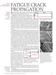
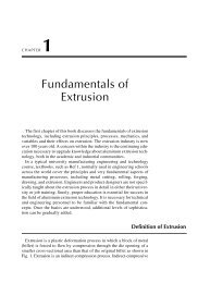
Fig. ! Schematic of a modern 50 kg (110 Ib) vacuum arc skull melting <strong>and</strong> casting<br />
furnace. 1, fast retraction system; 2, power cables; 3, electrode feeder<br />
ram; 4, power supplies; 5, consumable electrode; 6, skull crucible; 7, tundish shield; 8,<br />
mold arrangement; 9, centrifugal casting system; 10, chamber lid carriage<br />
<strong>Vacuum</strong> arc skull casting furnaces basi-<br />
cally consist of a vacuum-tight chamber in<br />
which a titanium or titanium alloy electrode<br />
is driven down into a water-cooled copper<br />
crucible. The dc power supply provides the<br />
fusing current needed to strike an electric<br />
arc between the consumable electrode <strong>and</strong><br />
the crucible. Because the crucible is water<br />
cooled, a solidified titanium skull forms at<br />
the crucible surface, thus avoiding direct<br />
contact between melt <strong>and</strong> crucible.<br />
Copyright © 2008 <strong>ASM</strong> <strong>International</strong> ®<br />
All rights reserved.<br />
www.asminternational.org<br />
<strong>Vacuum</strong> <strong>Melting</strong> <strong>and</strong> <strong>Remelting</strong> <strong>Processes</strong> / 409<br />
Once the predetermined amount of liquid<br />
titanium is contained in the crucible, the<br />
electrode is retracted, <strong>and</strong> the crucible is<br />
tilted to pour the melt into the investment<br />
casting mold positioned below. For opti-<br />
mum mold filling, the mold can be preheat-<br />
ed <strong>and</strong>/or rotated on a centrifugal turntable.<br />
Figure 1 shows the operating principle of a<br />
modern 50 kg (110 lb) vacuum arc skull melt-<br />
ing furnace. At an operating pressure of ap-<br />
proximately 1 Pa (10 -2 mbar, or 0.075 torr),<br />
the specific working current ranges from ap-<br />
proximately 1 kA/kg for small furnaces to<br />
about 0.2 kA/kg for large pouring weights.<br />
This batch-type skull melting furnace allows<br />
for cycle times of approximately 1 h for a full<br />
50 kg (110 lb) pumping/melting/casting cycle,<br />
<strong>and</strong> in principle three consecutive pours can<br />
be obtained from one electrode. This furnace<br />
basically consists of a vacuum chamber, an<br />
arc voltage-controlled electrode drive sys-<br />
tem, a skull crucible, a centrifugal casting<br />
system with stepless adjustable turntable<br />
speed, an automatically sequenced vacuum<br />
pump system, a power supply, <strong>and</strong> an elec-<br />
trical control system with control desk.<br />
The cylindrical vacuum chamber is<br />
equipped with two large dished doors that<br />
support the crucible with the tilting mecha-<br />
nism, the mold platform with the centrifugal<br />
casting system, <strong>and</strong> the casting tundish with<br />
its cover. The crucible support system with<br />
an additional detachable device is also used<br />
for electrode loading. The chamber is jack-<br />
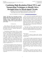
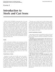
Fie. 2 Schematic of a modern semicontinuously operating vacuum arc skull melter<br />
for charge weights of up to 1000 kg (2200 Ib). 1, fast retraction system;<br />
2, power cables; 3, power supplies; 4, electrode feeder ram; 5, consumable electrode;<br />
6, skull crucible; 7, crucible carriage; 8, tundish shield; 9, mold arrangement; 10,<br />
vacuum pumping system; 11, centrifugal casting system<br />
- 9<br />
- 10<br />
11
<strong>ASM</strong> H<strong>and</strong>book Volume 15: Casting (#05115G)<br />
410 / Foundry Equipment <strong>and</strong> Processing<br />
eted for water cooling in regions that are<br />
subject to heat radiation.<br />
A top flange with a throat carries the<br />
electrode chamber <strong>and</strong> the electrode feed-<br />
ing system. Viewing ports allow for video<br />
monitoring of the melting <strong>and</strong> pouring. A<br />
vacuum pumping port is located in the cy-<br />
lindrical portion of the chamber.<br />
Figure 2 shows a semicontinuously oper-<br />
ated vacuum arc skull melter for charge<br />
weights of up to 1000 kg (2200 lb). The<br />
principal difference between this furnace<br />
<strong>and</strong> the smaller model (Fig. l)---apart from<br />
capacity-related layout features--is the<br />
rectangular vacuum chamber. Again, the<br />
crucible <strong>and</strong> the tilting mechanism are car-<br />
ried by a dished door.<br />
In this furnace design, the centrifugal cast-<br />
ing system is introduced from the bottom of<br />
the chamber to allow the horizontal connec-<br />
tion of a separate cooling chamber, if desired.<br />
Molds are loaded from the back side into the<br />
chamber <strong>and</strong> can be discharged through a<br />
front door, which also allows the use of a<br />
cooling <strong>and</strong> charging chamber with lock<br />
valves for continuous mold transport flow.<br />
Modern vacuum arc skull melting furnac-<br />
es are usually equipped with:<br />
• Coaxial power feed directly to the skull<br />
crucible to avoid electromagnetic fields<br />
that can disturb the melt bath<br />
• Programmable control systems for cruci-<br />
ble tilting to allow repeatable pouring<br />
profiles for consistent parameters<br />
• Highly accurate electrode weighing sys-<br />
tem for precise determination of pouring<br />
weights<br />
• XYadjustment system for coaxial position-<br />
ing of the electrode in the skull crucible<br />
• Compact air-cooled power-supply mod-<br />
ules of high capacity for achieving high<br />
melt rates, thinner skulls, <strong>and</strong> corre-<br />
spondingly increased yields above 80%<br />
• Proven vacuum pumping <strong>and</strong> measuring<br />
systems<br />
• Forced argon cooling systems for faster<br />
mold cooling<br />
Electron Beam <strong>Melting</strong> <strong>and</strong> Casting<br />
W. Dietrich <strong>and</strong> H. Stephan, Leybold AG, West Germany<br />
Electron beam melting <strong>and</strong> casting tech-<br />
nology is accepted worldwide for the pro-<br />
duction of niobium <strong>and</strong> tantalum ingots<br />
weighing up to 2500 kg (5500 Ib) in furnaces<br />
with electron beams of 200 to 1500 kW.<br />
Another application in East Germany <strong>and</strong><br />
other Soviet bloc countries is the produc-<br />
tion of steel ingots weighing 3.3 to 18 Mg<br />
(3.6 to 20 tons) using electron beams of up<br />
to 1200 kW. Furnaces of up to 2400 kW in<br />
electron beam power have been used since<br />
1982 for recycling titanium scrap to produce<br />
4.8 Mg (5.3 ton) slabs 1140 mm (45 in.)<br />
wide. Furnaces of 200 to 1200 kW are used<br />
to refine nickel-base superalloys. Other<br />
metals, such as vanadium <strong>and</strong> hafnium, are<br />
melted <strong>and</strong> refined in furnaces between 60<br />
<strong>and</strong> 260 kW. Approximately 150 furnaces<br />
with melting powers ranging from 20 to 300<br />
kW are in operation in research facilities.<br />
These furnaces are used in the development<br />
of new grades <strong>and</strong> purities of conventional<br />
Table 1 Comparison of characteristics of electron beam melting <strong>and</strong> competing processes<br />
Siotering ] I <strong>Vacuum</strong> arc melting I [<br />
Metal I Advantages Limitations Advantages Limitations<br />
Tungsten,<br />
molybdenum ....... Small grain size;<br />
most often used<br />
Tantalum, niobium... Small grain size;<br />
good workability<br />
Hafnium, vanadium ......... . - •<br />
Zirconium, titanium ......... • • •<br />
Refining limited;<br />
small batches;<br />
high energy<br />
consumption<br />
Same as above;<br />
rarely applied<br />
Same as above<br />
Not used<br />
Moderate grain size;<br />
acceptable workability;<br />
large ingots; low energy<br />
consumption<br />
Alloying; moderate grain<br />
size; large ingots; low<br />
energy consumption<br />
Alloying during remelting<br />
Very low contamination;<br />
wide range of alloying<br />
possible; large ingots;<br />
low energy consumption;<br />
economical melting<br />
Refining limited;<br />
costly electrode<br />
preparation; melting<br />
dangerous<br />
Refining limited;<br />
expensive electrode;<br />
melting dangerous<br />
Almost no refining;<br />
costly electrode<br />
preparation; melting<br />
dangerous<br />
Limited refining;<br />
expensive feedstock<br />
preparation; only<br />
round ingots<br />
<strong>and</strong> exotic metals <strong>and</strong> alloys, for example,<br />
uranium, copper, precious metals, rare-<br />
earth alloys, intermetallic materials, <strong>and</strong><br />
ceramics. The total power of installed elec-<br />
tron beam melting <strong>and</strong> casting furnaces<br />
worldwide was approximately 25 000 kW at<br />
the end of 1987.<br />
Electron beam melting <strong>and</strong> casting in-<br />
cludes melting, refining, <strong>and</strong> conversion<br />
processes for metals <strong>and</strong> alloys. In electron<br />
beam melting, the feedstock is melted by<br />
impinging high-energy electrons. Electron<br />
beam refining takes place in vacuum in the<br />
pool of a water-cooled copper crucible,<br />
ladle, trough, or hearth. In electron beam<br />
refining, the material solidifies in a wa-<br />
ter-cooled continuous casting copper cruci-<br />
ble or in an investment ceramic or graphite<br />
mold. This technology can be used for all<br />
materials that do not sublimate in vacuum.<br />
Competing processes include sintering<br />
(for example, for refractory metals), vacu-<br />
um arc melting <strong>and</strong> remelting (for reactive<br />
metals <strong>and</strong> superalloys), <strong>and</strong> electroslag<br />
melting <strong>and</strong> vacuum induction melting (for<br />
superaUoys, specialty steels, <strong>and</strong> nonfer-<br />
rous metals). Some advantages <strong>and</strong> limita-<br />
tions of the competing vacuum processes<br />
are given in Table 1. Additional information<br />
on some of these processes is available in<br />
the sections "<strong>Vacuum</strong> Arc <strong>Remelting</strong><br />
(VAR)," "Electroslag <strong>Remelting</strong> (ESR),"<br />
<strong>and</strong> "<strong>Vacuum</strong> Induction <strong>Melting</strong> (VIM)" in<br />
this article.<br />
Electron Beam <strong>Melting</strong> <strong>and</strong><br />
Casting Characteristics<br />
The characteristics of electron beam<br />
melting <strong>and</strong> casting technology are:<br />
• The flexibility <strong>and</strong> controllability of the<br />
process temperature, speed, <strong>and</strong> reaction<br />
• The use of a wide variety of feedstock<br />
Electron beam melting I<br />
Advantages Limitations<br />
Highest possible purity; Large grain size;<br />
economical feedstock brittle product;<br />
preparation; large very rarely applied<br />
ingots; low energy<br />
consumption<br />
Same as above; most Alloying limited<br />
frequently used<br />
Good refining;<br />
economical feedstock<br />
preparation <strong>and</strong> ingot<br />
production; most<br />
often used<br />
Economical feedstock<br />
preparation; refining<br />
of high-density<br />
inclusions; melting of<br />
slabs, ingots, <strong>and</strong><br />
rods; high production<br />
rate; low energy<br />
consumption<br />
Copyright © 2008 <strong>ASM</strong> <strong>International</strong> ®<br />
All rights reserved.<br />
www.asminternational.org<br />
High melting costs<br />
Alloying limited;<br />
material losses<br />
from splatter; high<br />
furnace investment
<strong>ASM</strong> H<strong>and</strong>book Volume 15: Casting (#05115G)<br />
materials in terms of material quality,<br />
size, <strong>and</strong> shape<br />
• The different methods of material pro-<br />
cessing available<br />
• Product quality, size, <strong>and</strong> quantity<br />
Contamination-free<br />
environment <strong>and</strong><br />
crucible<br />
Material evaporation.-- ,<br />
<strong>and</strong> splattering<br />
Reflected \..~__.~,<br />
electron beam<br />
X-ray emission<br />
Flexible melting rate<br />
<strong>and</strong> refining<br />
dwell time<br />
Feedstock<br />
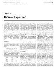
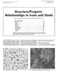
Fig. 1 Schematic of the electron beam melting process<br />
(a)<br />
li' i<br />
~! (f)<br />
Contamination of the product is avoided by<br />
melting in a controlled vacuum <strong>and</strong> in wa-<br />
ter-cooled copper crucibles (Fig. 1).<br />
The energy efficiency of electron beam<br />
processing exceeds that of competing pro-<br />
Electron beam gun<br />
Flexible power <strong>and</strong><br />
power distribution<br />
<strong>Vacuum</strong> <strong>Melting</strong> <strong>and</strong> <strong>Remelting</strong> <strong>Processes</strong> / 411<br />
Scanning electron beam<br />
Drip melt area<br />
Refining in the<br />
pool zone<br />
i ( , ' ) ~ (g) (h)<br />
Water-cooled copper crucible<br />
Continuous casting <strong>and</strong><br />
solidifying ingot<br />
Fig. 2 Examples of electron beam melting <strong>and</strong> casting processes. (a) Button melting with controlled solidification<br />
for quantitative determination of low-density inclusions. (b) Consolidation of raw material, chips, <strong>and</strong> solid<br />
scrap to consumable electrodes for vacuum arc or electron beam remelting. (c) Drip melting of horizontally or vertically<br />
fed feedstocks. (d) Continuous flow refining/melting. (e) Floating zone melting. (f) Investment casting. (g) Pelletizing<br />
(manufacture of pellets from scrap <strong>and</strong> other materials for scrap recycling). (h) Atomization <strong>and</strong> granulation of<br />
refractory <strong>and</strong> reactive metals<br />
(e) (b) /~<br />
Copyright © 2008 <strong>ASM</strong> <strong>International</strong> ®<br />
All rights reserved.<br />
www.asminternational.org<br />
cesses because of the control of the beam<br />
spot dwell time <strong>and</strong> distribution at the areas<br />
to be melted or maintained as liquid. In<br />
addition, unnecessary heating of the ingot<br />
pool, as occurs in vacuum arc remelting, for<br />
example, is avoided. Power losses of the<br />
electron beam inside the gun <strong>and</strong> between<br />
the gun nozzle <strong>and</strong> the target are very small,<br />
but approximately 20% of the beam power<br />
is lost because of beam reflection, radiation<br />
of the liquid metal, <strong>and</strong> heat conductivity of<br />
the water-cooled trough <strong>and</strong> crucible walls.<br />
Electron Beam <strong>Melting</strong><br />
<strong>and</strong> Casting <strong>Processes</strong><br />
From the large variety of electron beam<br />
melting <strong>and</strong> casting processes shown in Fig.<br />
2 only the processes illustrated in (a), (c),<br />
(d), <strong>and</strong> (f) are related to processes used in<br />
foundry technology:<br />
• Button melting processes for the quality<br />
control of steel <strong>and</strong> superalloy cast parts<br />
to control the content of low-density in-<br />
clusions<br />
• Drip melting process for the preparation<br />
of refractory <strong>and</strong> reactive metal feedstock<br />
material for electron beam <strong>and</strong> VAR skull<br />
melting <strong>and</strong> casting<br />
• Continuous flow melting process for the<br />
feedstock refining of superalloys for VIM<br />
<strong>and</strong> electron beam casting<br />
• Electron beam investment casting process<br />
Electron Beam Heat<br />
Source Specifmcat,ons<br />
For all electron beam melting <strong>and</strong> casting<br />
processes, except for the crucible-free float-<br />
ing zone melting process, Pierce-type elec-<br />
tron beam guns with separately evacuated<br />
beam generating <strong>and</strong> prefocusing rooms are<br />
the key components of the furnaces used.<br />
The essential features of these guns are:<br />
• Large power range of 0 to 1200 kW<br />
• Long free beam path of 250 to 1500 mm<br />
(10 to 60 in.) <strong>and</strong> the adjustable beam<br />
power distribution<br />
• Beam deflection angle of ---45 ° <strong>and</strong> spot<br />
frequency up to 500 Hz<br />
Schematics of electron beam consolidation <strong>and</strong> drip melting processes. (a) Consolidation of coarse <strong>and</strong> solid scrap. (b) Continuous consolidation of raw material, chips,<br />
Fig. 3 <strong>and</strong> solid scrap by direct feeding into a continuous casting crucible. (c) Drip melting of horizontally fed compacts, sintered bars, or consolidates for initial melting of<br />
reactive <strong>and</strong> refractory metals. (d) Drip melting of vertically fed vacuum induction melted or conventionally melted electrodes. (e) Drip melting of horizontally <strong>and</strong> vertically fed<br />
materials for the production of alloys from feedstocks with very different melting points
<strong>ASM</strong> H<strong>and</strong>book Volume 15: Casting (#05115G)<br />
412 / Foundry Equipment <strong>and</strong> Processing<br />
Table 2 <strong>Melting</strong> <strong>and</strong> refining data of refractory <strong>and</strong> reactive metals <strong>and</strong> alloy steels gained in laboratory <strong>and</strong><br />
pilot production furnaces<br />
Electron beam Total specific Interstitial elements<br />
Ingot Ingot Integral power of Operating vacuum melting in feedstock<br />
Feedstock size, diameter, weight, melting rate, second melt, pressure of last melt, energy, Material <strong>and</strong> final ingot, ppm Hardness,<br />
Metal mm (in.) mm (in.) kg (Ih) kg/h (Ib/h) kW Pa (tort) kW • h/kg yield, % C O N H HB<br />
Tungsten .......... 40 (1.6) diam<br />
55 (2.2) diam,<br />
100 (4) long<br />
Tantalum ......... 60 (2.4) diam<br />
60 (2.4) square,<br />
160 (6.3) long<br />
Molybdenum ...... 100 (4) diam<br />
100 (4) diam<br />
120 (4.7) square,<br />
180 (7.1) long<br />
Niobium ......... 80 (3.2) square,<br />
150 (6) long<br />
120 (4.7) square,<br />
180 (7. I) long<br />
Hafnium ......... 60 (2.4) square<br />
80 (3.2) diam<br />
100 (4) diam<br />
100 (4) diam<br />
Zirconium ....... 60 (2.4) square,<br />
100 (4) long<br />
60 (2.4) square,<br />
150 (6) long<br />
Vanadium ....... 60 (2.4) diam,<br />
80 (3.2) long<br />
Titanium ........ 100 (4) diam<br />
Ti-6AI-4V ....... • • •<br />
Ti-8Al-lMo-IV .... 100 (4) diam<br />
4340 steel ......... 80 (3.2) diam<br />
60 (2.4)<br />
115 (4.5)<br />
80 (3.2)<br />
160 (6.3)<br />
100 (4)<br />
180 (7.1)<br />
150 (6)<br />
180 (7.1)<br />
80 (3.2)<br />
130 (5.1) 173 (380)<br />
100 (4) 19.5 (43)<br />
150 (6) 179 (395)<br />
80 (3.2) 7.7 (17)<br />
100 (4) 28.2 (62)<br />
100 (4) 28.2 (62)<br />
150 (6) 31 (70)<br />
150 (6) 31 (70)<br />
(a) The reproducibility of the refining data could not be confirmed.<br />
• Usable vacuum pressure range between I<br />
<strong>and</strong> 0.0001 Pa (10 -2 <strong>and</strong> 10 -6 mbar, or 7.5<br />
× 10 -3 <strong>and</strong> 7.5 x 10 -7 torr)<br />
• Reliability of the gun <strong>and</strong> cathode system<br />
The power control <strong>and</strong> distribution system<br />
allows a very accurate distribution of beam<br />
power <strong>and</strong> energy for achieving the required<br />
heating for material melting, superheating,<br />
refining, <strong>and</strong> electrothermal effects.<br />
Button <strong>Melting</strong> for<br />
Quality Control<br />
The button melting process (Fig. 2a) serves<br />
to control the quality of feedstock materials<br />
for investment casting <strong>and</strong> to produce casting<br />
samples• In contrast to the conventional elec-<br />
tron beam melting process, this process is not<br />
used for refining, but only for flotation <strong>and</strong><br />
concentration of low-density inclusions• Dur-<br />
ing the eight-step process, the sample is heat-<br />
ed <strong>and</strong> drip melted. Low-density inclusions<br />
are floated to the surface <strong>and</strong> concentrated in<br />
the center of the pool of molten metal during<br />
controlled solidification by computer-con-<br />
trolled reduction of beam power <strong>and</strong> circular<br />
electrothermal stirring. The concentrated im-<br />
purities can be identified <strong>and</strong> evaluated by<br />
conventional metallographic methods, but the<br />
size of the raft gives the first indication of the<br />
quantity of impurities in the metal.<br />
37 (80) 10.5 (23)<br />
200 (440) 20 (44)<br />
65 (145) 16.7 (37)<br />
523 (1150) 38.4 (85)<br />
64 (140) 12.5 (27.5)<br />
408 (900) 50.2 (111)<br />
227 (500) 17.6 (39)<br />
326 (720) 13.2 (29)<br />
40 (90) 1.7 (3.7)<br />
7.5 (16.5)<br />
14.3 (31.5)<br />
73 (161)<br />
2.8 (6.2)<br />
45.2 (100)<br />
22.5 (50)<br />
10 (22)<br />
80 (176)<br />
119<br />
3O0<br />
130<br />
371<br />
130<br />
290<br />
240<br />
218<br />
80<br />
110<br />
80<br />
250<br />
80<br />
87<br />
6O<br />
52<br />
80<br />
8 x 10 -3 (6x 10 -s)<br />
2 x 10 -2 (1.5 × 10 -4 )<br />
8 X 10 -3 (6 × 10 -5)<br />
3 × 10 -3 (2 × 10 -s)<br />
8 × 10 -4 (6 X 10 -6)<br />
10 -3 (7.5 x 10 -6)<br />
10 -2 (7.5 x 10 -5)<br />
5 x 10 -3 (3.8 X 10 -s)<br />
5 x 10 -3 (3.8 X 10 -s)<br />
4 X 10 -3 (3 x 10 -s)<br />
8 x 10 -3 (6 x 10 -5 )<br />
2 x 10 -2 (1.5 x 10 -4 )<br />
8 x 10 -3 (6 x 10 -5 )<br />
0.8 (6 x 10 -3)<br />
0.4 (3 x 10 -3 )<br />
4 x 10 -3 (3 × 10 -5 )<br />
2.0 (0.015)<br />
Most button melting furnaces are com-<br />
pletely automated <strong>and</strong> microprocessor con-<br />
trolled to guarantee process reproducibility•<br />
<strong>Melting</strong> is usually carried out in the pres-<br />
sure range of l to 0.001 Pa (10 -2 to l0 -5<br />
mbar, or 7.6 × 10 -3 to 7.6 × 10 -6 torr).<br />
Drip <strong>Melting</strong><br />
The drip melting processes (Fig. 3c <strong>and</strong> d)<br />
are primarily used for the production of<br />
clean, mostly ductile ingots of refractory<br />
<strong>and</strong> reactive metals or of specialty steels•<br />
The feedstock for the first melt (Fig. 3c) can<br />
be compacted sponge, granular, powder, or<br />
scrap, which might be presintered in a vac-<br />
uum heating furnace• In some cases, loose<br />
raw materials can be consolidated in a wa-<br />
ter-cooled copper trough (Fig. 3a). The con-<br />
solidated ingot can then be fed horizontally<br />
for drip melting• Raw material that is con-<br />
tinuously consolidated in a water-cooled<br />
copper crucible with a retractable bottom<br />
plate (Fig. 3b) can be fed horizontally or<br />
vertically for drip melting. In both consoli-<br />
dation processes, only 20 to 80% of the<br />
material is melted• Refining <strong>and</strong> losses of<br />
material by splattering are negligible•<br />
Drip melting of horizontally fed compacts<br />
is the most frequently used process for the<br />
production of ingots from refractory or re-<br />
active metals• The resulting ingot is of suf-<br />
10.3<br />
9.9<br />
6.0<br />
8.30<br />
10.4<br />
5.2<br />
12.3<br />
15.9<br />
38<br />
14.7<br />
4.6<br />
2.6<br />
3.1<br />
1.91<br />
2.66<br />
1.67<br />
1.0<br />
Copyright © 2008 <strong>ASM</strong> <strong>International</strong> ®<br />
All rights reserved.<br />
www.asminternational.org<br />
• .. 70 4100 30 10<br />
93.1 10 8 5 1<br />
• .. 200 5000 50 20<br />
90 10 8 7 1<br />
• .. 100 1200 140 10<br />
92 10 75 30 1<br />
...... 650 13 10<br />
91.8 6 15 13 2<br />
- • • 170 810 50 10<br />
95 12 10 10 2<br />
• • • 200 750 60 10<br />
96.8 10 12 11 2<br />
... 160 5220 554 35<br />
87 12 106 60 5<br />
• .. 80 4500 330 40<br />
96.8 6 111 52 8<br />
...... 1870 95 2<br />
93.1 • • • 170 25 I<br />
• • • 500 900 100 2<br />
93.5 100 200 50 1<br />
...... 950 95 30<br />
88.2 • • • 545 30 3<br />
...... 950 95 30<br />
...... 735 48 9<br />
...... 1045(a) 210(a) 16(a)<br />
91 ... 235(a) 95(a) 13(a)<br />
...... 2180 100 30<br />
99 • • - 1850 80 16<br />
...... 890 70 ' • •<br />
98 • • • 730 50 • • •<br />
• • • 3900 63 100 0.3<br />
93 4300 2.4 26 0.08<br />
99 3622 10 78 0.10<br />
200<br />
210<br />
65<br />
69<br />
140<br />
140<br />
77<br />
66<br />
160<br />
170<br />
120<br />
125<br />
30-100<br />
ficient purity, but has an area of inhomoge-<br />
neity caused by the shadow of the<br />
horizontally fed bar. Two or more electron<br />
guns are used in drip melting to make use of<br />
reflected electron beams <strong>and</strong> to reduce<br />
evaporation <strong>and</strong> splattering• The end of a<br />
compact is welded to the front of the fol-<br />
lowing one to avoid dropping semisolid ma-<br />
terial into the pool. Table 2 lists processing<br />
parameters that have been successfully<br />
used to electron beam melt various reactive<br />
<strong>and</strong> refractory metals <strong>and</strong> 4340 alloy steel.<br />
Vertical Feeding of Ingots. Refractory<br />
<strong>and</strong> reactive metal ingots of high purity,<br />
homogeneity, <strong>and</strong> smooth surface are re-<br />
melted by vertical feeding (Fig. 3d). The<br />
molten metal droplets run down the conical,<br />
rotating electrode tip, are refined, <strong>and</strong> then<br />
drop into the pool center• The crucible pool<br />
is normally of the same diameter as the<br />
electrode but is sometimes smaller or larg-<br />
er. It is kept in the liquid state to allow final<br />
refining <strong>and</strong> to guarantee ingot homogene-<br />
ity. Because two or more electron guns are<br />
used, the entire pool can be equally bom-<br />
barded; thus, shadow effects of the elec-<br />
trode can be eliminated•<br />
Simultaneous melting of horizontally <strong>and</strong><br />
vertically fed electrodes (Fig. 3e) can be<br />
used for the production of critical alloys. In<br />
this case, the feedstock should be of the<br />
desired purity•
<strong>ASM</strong> H<strong>and</strong>book Volume 15: Casting (#05115G)<br />
Drip melting of 330 mm (13 in.) square steel billet in a 1100 kW single-gun furnace. Melt rate: 1000 kg/<br />
Fig. 4 h (2200 Ib/h). Courtesy of VEB-I:delstahlwerk, East Germany<br />
Horizontally Fed Ingots. Drip melting of<br />
horizontally fed material with a single elec-<br />
tron gun (Fig. 4) is used for refining some<br />
steel alloys in East Germany <strong>and</strong> other<br />
Soviet bloc countries. In this process, the<br />
feedstock size is smaller than the pool di-<br />
ameter to minimize the shadow effect of the<br />
horizontally fed bar. In production units,<br />
feeding can be carried out from two oppo-<br />
site sides.<br />
Other Process Considerations. To en-<br />
sure the production of clean, homogeneous<br />
metals <strong>and</strong> alloys in electron beam drip<br />
melting furnaces, various aspects of mate-<br />
rial processing <strong>and</strong> h<strong>and</strong>ling must be con-<br />
trolled. Key considerations include:<br />
• Dimensions <strong>and</strong> quality of the feedstock,<br />
<strong>and</strong> the feeding system used<br />
• Ingot cooling <strong>and</strong> unloading during melt-<br />
ing of another ingot<br />
• Passivation <strong>and</strong> removal of condensates<br />
from the melt chamber<br />
• Planning of melt sequences to minimize<br />
the number of furnace cleanings required<br />
• Routine preventive furnace maintenance<br />
to ensure reliability<br />
• Operator skill in operation of the furnace<br />
• Material yield <strong>and</strong> energy consumption<br />
Equipment for Drip <strong>Melting</strong><br />
The essential equipment groups required<br />
for drip melting--melting furnaces, control<br />
systems, <strong>and</strong> power supply units---are all im-<br />
portant for achieving optimum productivity.<br />
The melting furnace (Fig. 5) includes the<br />
electron beam gun as the heat source, ma-<br />
terial feeding <strong>and</strong> ingot withdrawal systems,<br />
a crucible for material solidification, <strong>and</strong> a<br />
vacuum system to maintain the low pres-<br />
sure. Process observation, both visually<br />
<strong>and</strong> with video systems, is possible through<br />
viewports. The melt chamber flanges are<br />
equipped with x-ray absorbing steel boards,<br />
Copyright © 2008 <strong>ASM</strong> <strong>International</strong> ®<br />
All rights reserved.<br />
www.asminternational.org<br />
<strong>Vacuum</strong> <strong>Melting</strong> <strong>and</strong> <strong>Remelting</strong> <strong>Processes</strong>/413<br />
<strong>and</strong> interlocking systems prevent operation<br />
failures <strong>and</strong> accidents.<br />
The control system allows the adjustment<br />
<strong>and</strong> control of such operating process pa-<br />
rameters as electron beam power, operating<br />
vacuum level, material feed rate, <strong>and</strong> ingot<br />
withdraw speed. The control system also<br />
records <strong>and</strong> logs the process data.<br />
Power Supply Units. One or more high-<br />
voltage power supply units are needed to<br />
supply the electron beam guns with the<br />
required continuous voltage (30 to 40 kV).<br />
The beam power of each gun can be adjust-<br />
ed between zero <strong>and</strong> maximum power with<br />
an accuracy of -+2%.<br />
Other Equipment. Large production fur-<br />
naces are equipped with lock-valve systems<br />
to allow simultaneous melting <strong>and</strong> unload-<br />
ing of ingots without breaking the vacuum<br />
in the melt chamber. Production is thus<br />
limited only when the condensate remaining<br />
in the melt chamber requires cleaning or<br />
when a different alloy is to be melted.<br />
Characteristics of Electron<br />
Beam Drip Melted Metals<br />
Electron beam melted <strong>and</strong> refined material<br />
is of the highest quality. The amount of inter-<br />
stitials present is very low, <strong>and</strong> trace elements<br />
of specific high vapor pressure can also be<br />
reduced to very low values (Ref 1, 2).<br />
Reactive <strong>and</strong> Refractory Metals<br />
Tantalum <strong>and</strong> niobium ingots have<br />
smooth surfaces <strong>and</strong> are of sufficient ductil-<br />
ity that they can be cold worked, <strong>and</strong> sheets<br />
<strong>and</strong> wires can be produced.<br />
Tungsten <strong>and</strong> molybdenum ingots are<br />
also of the highest possible purity, but the<br />
ingots are brittle because of the very large<br />
grain size <strong>and</strong> the concentration of impuri-<br />
ties at grain boundaries.<br />
Hafnium. Electron beam melted hafnium<br />
is of higher ductility than the vacuum arc<br />
remelted metal (Ref 3). The main application<br />
of electron beam melted hafnium is as control<br />
elements for submarine nuclear reactors.<br />
Vanadium is refined by electron beam<br />
drip melting. The aluminothermically pro-<br />
duced feedstock is drip melted in several<br />
steps. During this procedure, the ingot diam-<br />
eter is reduced at each step by approximately<br />
30 to 40 mm (1.2 to 1.6 in.) to obtain an ingot<br />
30 to 40 mm (1.2 to 1.6 in.) in diameter,<br />
regardless of the initial ingot diameter. The<br />
clean vanadium ingots are primarily used in<br />
nuclear reactor applications (Ref 4).<br />
Applications for electron beam melted<br />
refractory <strong>and</strong> reactive metals are listed in<br />
Table 3.<br />
Steels<br />
The purity <strong>and</strong> properties of electron beam<br />
melted steels are in some respects better than<br />
those of vacuum arc <strong>and</strong> electroslag remelted<br />
steels, but the processing costs are higher.<br />
The electron beam melting of steel is primar-
<strong>ASM</strong> H<strong>and</strong>book Volume 15: Casting (#05115G)<br />
414 / Foundry Equipment <strong>and</strong> Processing<br />
<strong>Melting</strong> chamber<br />
Feeding systems<br />
Oil diffusion pump<br />
Water-cooled<br />
copper crucible<br />
Device for ingot<br />
withdrawal<br />
U I<br />
/<br />
M<br />
Electron beam<br />
Deflected<br />
electron beam<br />
Charging valves<br />
<strong>Remelting</strong> rod<br />
Ingot<br />
Single-gun 1200 kW furnace for horizontal drip melting of steels. <strong>Melting</strong> rates of up to 1100 kg/h (2425<br />
Fig. 5 Ib/hl are possible.<br />
Table 3 Principal applications for vacuum arc remelted (VAR), electron<br />
beam melted (EB), <strong>and</strong> powder metallurgy (P/M) reactive <strong>and</strong> refractory<br />
metal ingots<br />
Metal Applications<br />
Reactive metals, VAR <strong>and</strong> EB melting<br />
Hafnium ..................................<br />
Vanadium .................................<br />
Zirconium .................................<br />
Titanium ..................................<br />
Refractory metals, EB melting <strong>and</strong> P/M<br />
Tungsten ..................................<br />
Tantalum .................................<br />
Molybdenum ..............................<br />
Niobium ..................................<br />
Flash bulbs <strong>and</strong> glow discharge tubes for the electronics<br />
industry; control rods <strong>and</strong> breakoff elements in submarine<br />
nuclear reactors<br />
Targets for high deposition rate sputtering processes in the<br />
electronics industry; breakoff elements, fixtures, <strong>and</strong> fasteners<br />
in nuclear reactors; st<strong>and</strong>ards for basic research; alloying<br />
element for certain high-purity alloys<br />
Getter material in tubes in the electronics industry; stripes for<br />
flash bulbs; fuel claddings, fasteners, <strong>and</strong> fixtures for nuclear<br />
reactors<br />
Components for bleaching equipment <strong>and</strong> desalination plants in<br />
the chemical industry; superconductive wires; turbine engine<br />
disks, blades <strong>and</strong> housings, rain erosion boards, l<strong>and</strong>ing legs,<br />
wing frames, missile cladding, <strong>and</strong> fuel containers in the<br />
aircraft <strong>and</strong> aerospace industries; shape memory alloys;<br />
biomedical fixtures <strong>and</strong> implants; corrosion resistant claddings<br />
Heating elements, punches <strong>and</strong> dies, <strong>and</strong> nonconsummable<br />
electrodes for arc melting <strong>and</strong> gas tungsten arc welding for<br />
metal processing equipment; targets for x-ray equipment <strong>and</strong><br />
high sputtering rate devices such as very large-scale integrated<br />
circuits, cathodes <strong>and</strong> anodes for electronic vacuum tubes in<br />
the electronics industry; radiation shields in the nuclear<br />
industry; cladding <strong>and</strong> fasteners for missile <strong>and</strong> reentry<br />
vehicles<br />
Condensers, autoclaves, heat exchangers, armatures, <strong>and</strong> fittings<br />
for the chemical industry; electrolytic capacitors for the<br />
electronics industry; surgical implants; fasteners for aerospace<br />
applications<br />
Dies for conventional <strong>and</strong> isothermal forging equipment;<br />
electrodes for glass melting; targets for x-ray equipment;<br />
cladding <strong>and</strong> fasteners for missile <strong>and</strong> reentry vehicles<br />
Superconductive wire for energy transmission <strong>and</strong> large magnets<br />
for the electrical <strong>and</strong> electronics industries; heavy ion<br />
accelerators <strong>and</strong> radio frequency cavities for nuclear<br />
applications; components for aircraft <strong>and</strong> aerospace<br />
applications<br />
Copyright © 2008 <strong>ASM</strong> <strong>International</strong> ®<br />
All rights reserved.<br />
www.asminternational.org<br />
ily used in East Germany <strong>and</strong> other Soviet<br />
bloc countries. The resulting ingots are up to<br />
1000 mm (40 in.) in diameter <strong>and</strong> weigh up to<br />
18 Mg (20 tons). The furnaces used have been<br />
in operation since 1965, <strong>and</strong> have beam pow-<br />
ers of up to 1200 kW. Larger furnaces for the<br />
production of ingots weighing up to 30 to 100<br />
Mg (33 to 110 tons) are under construction<br />
(Ref 5).<br />
The essential advantage of the electron<br />
beam melting of steel is the drastic reduction<br />
of metallic <strong>and</strong> nonmetallic impurities <strong>and</strong><br />
interstitial elements (Ref 6, 7). The principal<br />
applications for electron beam melted steels<br />
are in the machinery industry for parts for<br />
which high wear resistance <strong>and</strong> long service<br />
life are required. The extended service lives<br />
of the parts <strong>and</strong> the reduced manufacturing<br />
time (for example, less surface polishing is<br />
required for electron beam melted steel) can<br />
justify the higher material costs.<br />
The electron beam melting of steel <strong>and</strong><br />
superalloys can become much more eco-<br />
nomical when melting <strong>and</strong> refining are done<br />
by continuous flow melting or cold hearth<br />
refining. These melting <strong>and</strong> refining meth-<br />
ods reduce energy costs <strong>and</strong> minimize ma-<br />
terial losses.<br />
Continuous Flow Molting<br />
The continuous flow melting process (cold<br />
hearth refining process) (Fig. 6) was devel-<br />
oped approximately 10 years after drip melt-<br />
ing (Ref 8). Continuous flow melting is mainly<br />
used for refining specialty steels <strong>and</strong> superal-<br />
loys <strong>and</strong> for refining <strong>and</strong> recycling reactive<br />
metal scrap, especially Ti-6AI-4V from high-<br />
density tungsten carbide tool tips (Ref 9).<br />
Principles of<br />
Continuous Flow <strong>Melting</strong><br />
Continuous flow melting (Fig. 7) is the<br />
most flexible vacuum metallurgical melting<br />
process. It is a two-stage process in which<br />
the first step (material feeding, melting, <strong>and</strong><br />
refining) takes place in a water-cooled cop-<br />
per trough, ladle, or hearth. In the second<br />
step, solidification occurs in one of several<br />
round, rectangular, or specially shaped wa-<br />
ter-cooled continuous copper crucibles.<br />
Both process steps are nearly independent<br />
from each other; they are linked only by the<br />
continuous flow of the liquid metal stream.<br />
The major refining actions are carried out in<br />
the hearth, but some postrefining takes<br />
place in the pool of the continuous casting<br />
crucible, similar to the drip melting of hor-<br />
izontally fed billets. Refinement in continu-<br />
ous flow melting occurs by vacuum distilla-<br />
tion in the hearth pool, superheating, <strong>and</strong><br />
stirring of the molten metal pool.<br />
Removal of Impurities. Most impurities<br />
with densities lower than that of the melt (for<br />
example, metalloids in steels <strong>and</strong> superalloys)<br />
can be segregated by flotation <strong>and</strong> formed<br />
into a slag raft. The raft is then held in place<br />
by either mechanical or electrothermal
<strong>ASM</strong> H<strong>and</strong>book Volume 15: Casting (#05115G)<br />
Beam rot<br />
on the pc<br />
Programmed electron beams<br />
for refining low-density<br />
inclusions <strong>and</strong> maintaining a<br />
flat. shallow inaot oool<br />
Fig. 6 Schematic of the continuous flow melting process<br />
means. Impurities denser than the melt, such<br />
as tungsten carbide tool tips in titanium, are<br />
removed by sedimentation. Inclusions with<br />
densities such that efficient flotation or sedi-<br />
mentation does not occur can be partially<br />
removed by adhesion to the slag raft.<br />
Hearth dimensions are based on the type<br />
<strong>and</strong> amount of refining required. For exam-<br />
ple, hearths for vacuum distillation should<br />
be nearly square <strong>and</strong> relatively deep to<br />
allow sufficient melt stirring. For flotation<br />
refining, the hearth should be long <strong>and</strong><br />
narrow (for superalloys, approximately 10<br />
mm, or 0.4 in., of hearth length for each 100<br />
<strong>Vacuum</strong> <strong>Melting</strong> <strong>and</strong> <strong>Remelting</strong> <strong>Processes</strong> / 415<br />
3n beam<br />
feedstock<br />
lat<br />
9ntal bar feeding<br />
per<br />
anical<br />
val of<br />
~ions<br />
kg/h, or 220 lb/h, of melt rate is recommend-<br />
ed). Hearths for titanium alloy scrap recy-<br />
cling can be relatively short if all the mate-<br />
rials can be transported to the pool of the<br />
hearth rather than to the ingot pool.<br />
Feeding. Material feeding criteria include<br />
100% homogenous material transportation<br />
to avoid uncontrolled evaporation of alloy-<br />
ing elements <strong>and</strong> correct feeding into or<br />
above the hearth pool. Horizontal feeding of<br />
compacted, premelted, or cast material is<br />
most often used. Loose scrap <strong>and</strong> raw mate-<br />
rial are used only when compaction is too<br />
expensive. Feeding of liquid metal was used<br />
Table 4 Comparison of the characteristics of drip melting <strong>and</strong> continuous<br />
flow melting<br />
Characteristic Refractory metals Reactive metals, superalloys, <strong>and</strong> specialty steels<br />
Power density ............................. High Soft; smoothly distributed<br />
Inclusions ............................. Irrelevant Must be removed<br />
Ingot shape <strong>and</strong> structure ............... Round; coarse grain Round or flat; fine grain, segregation-free<br />
Mass production ....................... Low High<br />
Competitive economical processes ....... <strong>Vacuum</strong> arc remelting <strong>Vacuum</strong> arc remelting; electroslag remelting<br />
Preferred method ...................... Drip melting Continuous flow melting<br />
Copyright © 2008 <strong>ASM</strong> <strong>International</strong> ®<br />
All rights reserved.<br />
www.asminternational.org<br />
in one of the first continuous flow melting<br />
furnaces to produce a ferritic steel in a vacu-<br />
um induction furnace (Ref 10). Postrefining<br />
was carried out in a cascade of five hearths<br />
1.5 m (60 in.) long <strong>and</strong> 1 m (40 in.) wide.<br />
Casting <strong>and</strong> Solidification. The criteria<br />
for material casting <strong>and</strong> solidification include<br />
the shape of the final product <strong>and</strong> the solidi-<br />
fication rate required to avoid ingot tears or<br />
other defects <strong>and</strong> to ensure a homogeneous<br />
ingot structure. The multiple casting of small<br />
ingots is sometimes used, especially when<br />
forging is impossible because of the brittle-<br />
ness of the solidified material (for example<br />
MCrAly wear-resistant coating alloys). The<br />
casting of round <strong>and</strong> rectangular ingots <strong>and</strong><br />
slabs is common practice, <strong>and</strong> the continuous<br />
casting of hollow ingots is also being used<br />
(Ref I 1). The casting of segregation-free in-<br />
gots <strong>and</strong> ingots with a fine grain size is under<br />
development to improve the workability of<br />
superalloys (Ref 12, 13).<br />
Continuous Flow<br />
Versus Drip <strong>Melting</strong><br />
Table 4 compares the essential features of<br />
drip melting <strong>and</strong> continuous flow melting.<br />
Generally, continuous flow melting is used<br />
for all refractory metals, superalloys, <strong>and</strong><br />
specialty steels, especially when flotation or<br />
sedimentation of inclusions is required.<br />
Drip melting is used for refractory metals<br />
because of their high melting points <strong>and</strong> the<br />
resulting high heat losses to the water-<br />
cooled copper crucible. Depending on pro-<br />
duction quantity, double or triple drip melt-<br />
ing may require less energy than a single<br />
continuous flow melt of some materials,<br />
such as niobium.<br />
Refining <strong>and</strong> Production Data<br />
Data on continuous flow electron beam<br />
melting <strong>and</strong> refining in laboratory <strong>and</strong> pilot<br />
production furnaces are given in Table 5. The<br />
data demonstrate the effectiveness of the pro-<br />
cess in reducing impurities <strong>and</strong> interstitial<br />
elements. It can also be seen that the selective<br />
evaporation of chromium from superalloys<br />
can be controlled by the distribution of beam<br />
power at the trough pool <strong>and</strong> by controlling<br />
trough pool area <strong>and</strong> melt rate. The selective<br />
evaporation of aluminum from Ti-6A1-4V al-<br />
loy is much more difficult to control; addition-<br />
al aluminum must be used to compensate for<br />
the aluminum evaporated.<br />
Equipment for Continuous<br />
Flow Electron Beam <strong>Melting</strong><br />
The equipment required for continuous<br />
flow melting is different from that used in<br />
drip melting mainly because of the trough<br />
<strong>and</strong> the somewhat larger melting chamber.<br />
In addition, because of the materials often<br />
melted in the continuous flow process (su-<br />
peralloys <strong>and</strong> titanium alloys), additional<br />
instrumentation is often provided. This may<br />
include an ingot pool level control system,
<strong>ASM</strong> H<strong>and</strong>book Volume 15: Casting (#05115G)<br />
416 / Foundry Equipment <strong>and</strong> Processing<br />
/<br />
/-//~// .........<br />
Fig. 7 Four-gun 1200 kW combined electron beam drip melting <strong>and</strong> continuous flow melting furnace<br />
metal vapor <strong>and</strong> partial pressure analyzers,<br />
a two-color temperature control system,<br />
<strong>and</strong> a data logging system.<br />
Accurate beam power distribution is<br />
achieved in two- or three-gun furnaces by<br />
microprocessor control, which allows the<br />
splitting of a single beam to 64 locations <strong>and</strong><br />
the adjustment of dwell time at each loca-<br />
tion between 0.01 <strong>and</strong> 1000 s. The beam<br />
spot at each of the 64 locations can be<br />
scanned over an elliptical or rectangular<br />
area. With such systems, the required refin-<br />
ing can be achieved without unnecessary<br />
power consumption <strong>and</strong> evaporation of al-<br />
loying elements (Ref 15).<br />
Process observation is accomplished with<br />
a video monitoring system. Samples can be<br />
obtained from both the trough pool <strong>and</strong> the<br />
ingot pool for nearly continuous control of<br />
material quality.<br />
Feeding systems for continuous flow fur-<br />
naces must maintain homogeneity along the<br />
length of the feed material. The trough <strong>and</strong><br />
crucible should be easily accessible for con-<br />
venient maintenance, especially when dif-<br />
ferent alloys are to be melted in the same<br />
furnace.<br />
Characteristics of<br />
Continuous Flow<br />
Melted Materials<br />
Titanium ingots <strong>and</strong> slabs can be pro-<br />
duced from titanium scrap contaminated<br />
with tungsten carbide tool tips. The electron<br />
beam melted product contains tungsten car-<br />
Table 5 Refining <strong>and</strong> production data for the continuous flow melting of reactive <strong>and</strong> refractory metals <strong>and</strong><br />
stainless steels in laboratory <strong>and</strong> pilot production furnaces<br />
Electron Specific<br />
beam Operating melting ] Composition of feedstock <strong>and</strong> product [<br />
Feedstock size, Trough size, Ingot size, Ingot weight, Melt rate, power, pressure, energy, C, O, N, H, AI, V, Cr,<br />
Metal mm (in.) mm (in.) mm (in.) kg 0b) kg/h 0h/h) kW Pa (tort) kW • h/kg ppm ppm ppm ppm % % %<br />
Hafnium ........... 60 (2.4) square 120 × 250 100 (4) diam<br />
(5 x 10)<br />
Zirconium ........ I00 (4) square 120 x 300 150 (6)<br />
(5 x 12)<br />
Zirconium ........ 80 (3.2) square 120 x 300 100 (4)<br />
(5 x 12)<br />
Vanadium ........ 50 (2) square 120 x 300 100 (4)<br />
(5 x 12)<br />
Ti-6AI-4V ........ Swarf 120 x 300 150 (6)<br />
(5 x 12)<br />
Ti-6AI-4V ........ Solid scrap 120 x 300 150 (6)<br />
(5 × 12)<br />
Ti-6AI-4V ........ 125 (5) diam 150 × 400 2 x 75 (3)<br />
(6 × 16) diam<br />
Commercially pure<br />
titanium ........ 160 (6.3) 150 x 250 100 x 400<br />
(6 x 10) (4 x 16)<br />
Commercially pure<br />
titanium ...... Sponge 150 x 500 100 x 400<br />
(6 x 20) (4 x 16)<br />
Stainless steel .... 150 (6) diam 150 x 400 2 x 75 (3)<br />
(6 x 16) diam<br />
Alloy 718 ........ 133 (5.2) diam 150 x 400 2 x 75 (3)<br />
(6 x 16) diam<br />
AISI type 316<br />
stainless steel... 150 (6) diam 150 x 400 3 x 65 (2.6)<br />
(6 x 16) diam<br />
Source: Ref 14<br />
83.0 (183) 40 (88)<br />
90.5 (200) 42 (92.5)<br />
40.2 (89) 80 (176)<br />
. - - 20 (44)<br />
62.6 (138) 40 (88)<br />
62.6 (138) 70 (154)<br />
2 x 32 (70.5) 91 (200)<br />
96.4 (213) 86.3 (190)<br />
103.0 (227) 41.2 (91)<br />
2 × 55 (121) 136 (300)<br />
2 × 57 (126) 136 (300)<br />
3 x 41.5 136 (300)<br />
(91.5)<br />
180 4 x 10 -2<br />
(3 x 10 -4)<br />
185 3.5 X 10 -2<br />
(2.6 x 10 -4)<br />
140 3.5 X 10 -2<br />
(2.6 x l0 -4)<br />
130 1.5 x l0 2<br />
(1.1 x l0 4)<br />
122 2 X 10 -2<br />
(1.5 x 10 -4)<br />
140 7 × 10 2<br />
(5.3 x 10 4)<br />
147 6 X l0 2<br />
(4.5 x 10 -4)<br />
148 6 × 10 -2<br />
(4.5 × 10 -4)<br />
226 8 x 10 -2<br />
(6 x 10 -4)<br />
144 6 x 10 -2<br />
(4.5 x 10 4)<br />
156 6 × 10 -z<br />
(4.5 x 10 -4)<br />
156 6 X 10 -2<br />
(4.5 x 10 -4)<br />
Copyright © 2008 <strong>ASM</strong> <strong>International</strong> ®<br />
All rights reserved.<br />
www.asminternational.org<br />
4.5<br />
900 . . . . . . . . . . . . . . .<br />
600 . . . . . . . . . . . . . . .<br />
4.4<br />
950 95 30 .........<br />
540 30 3 .........<br />
1.75<br />
4000 800 10 .........<br />
1520 210 3 .........<br />
6.5<br />
1045 210 10 ... 99 '-"<br />
277 50 3 ... 99 .''<br />
3.0 400 2600 110 84 6.0 4.0 ''<br />
200 2700 110 22 4.4 4.2 ' "<br />
2.0 1520 1520 75 15 6.0 4.0 ' '<br />
• . . 1320 76 8 4.8 4.1 • '<br />
1.61 . . . . . . . . . . . . 6.0 4.0 • •<br />
. . . . . . . . . . . . 3.6 4.3 • •<br />
1.71 . . . . . . . . . . . . . . . . . . . . .<br />
5.5 . . . . . . . . . . . . . . . . . . . . .<br />
1.06 701 97 155 ......... 18.25<br />
536 33 68 ......... 18.11<br />
1.15 417 14 52 ......... 19.11<br />
363 17 34 .'' 0.72 ''' 18.73<br />
1.15 . . . . . . . . . . . . . . . . . . . . .