Manual - BRUNNER ELEKTRONIK
Manual - BRUNNER ELEKTRONIK
Manual - BRUNNER ELEKTRONIK

You also want an ePaper? Increase the reach of your titles
YUMPU automatically turns print PDFs into web optimized ePapers that Google loves.
<strong>Manual</strong><br />
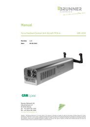
CANOpen Programmers Reference For AC Servo Drives PRG.1014<br />
Revision: 6. 7<br />
Datum: 07.03.2012<br />
Brunner Elektronik AG<br />
Industriestrasse 27<br />
CH-8335 Hittnau<br />
tel. +41 (0)44 953 1010<br />
fax. +41 (0)44 953 1019<br />
www.beh.ch info@beh.ch<br />
Copyright © 2009 Brunner Elektronik AG. Der gesamte Inhalt des Dokuments ist urheberrechtlich geschützt. Alle Rechte gehören der Brunner Elektronik AG. Das Reproduzieren,<br />
Übermitteln, Modifizieren oder Verknüpfen, für öffentliche oder kommerzielle Zwecke, ist ohne vorherige schriftliche Zustimmung der Brunner Elektronik AG untersagt.<br />
Sämtliche Angaben zu technischen Daten, Massen, Farben usw. sowie Produktänderungen bleiben unter Vorbehalt. Der für Anwendung und Ausrüstung Verantwortliche muss<br />
persönlich sicherstellen, dass jede Anwendung alle geltenden Anforderungen, Richtlinien und Vorschriften bezüglich Betrieb und Sicherheit erfüllt. Brunner Elektronik AG<br />
übernimmt keine Haftung für Schäden oder Verletzungen, die durch Installation oder Verwendung entstehen.
Index<br />
www.beh.ch<br />
1 Introduction 7<br />
1.1 Overwiew 7<br />
1.2 Related Documentation 7<br />
1.3 Copyright 7<br />
1.4 Document Validity 7<br />
1.5 Product Warning 7<br />
1.6 Object Description Conventions 7<br />
2 Communication 8<br />
2.1 Communication Object (COB) 8<br />
2.2 Communication Model 8<br />
2.3 Predefined Communication Objects 9<br />
2.3.1 NMT Service 9<br />
2.3.2 SYNC Messages 9<br />
2.3.3 HEARTBEAT Protocol 9<br />
2.3.4 EMERGENCY Messages 9<br />
2.3.5 SDO Messages 9<br />
2.3.6 PDO Messages 10<br />
2.4 Commom Communication profile objects 10<br />
2.4.1 Object 1000h Device Type 10<br />
2.4.2 Object 1001h Error Register 11<br />
2.4.3 Object 1002h Manufacturer Status Register 11<br />
2.4.4 Object 1003h Pre- defined Error Field 12<br />
2.4.5 Object 1008h Manufacturer Device Name 13<br />
2.4.6 Object 1009h Manufacturer Hardware Version 13<br />
2.4.7 Object 100Ah Manufacturer Software Version 13<br />
2.4.8 Object 1010h Store Parameter Field 14<br />
2.4.9 Object 1011h Restore Default Parameter 14<br />
2.4.10 Object 1015h Inhibit Time Emergency 15<br />
2.4.11 Object 1018h Identity Object 16<br />
2.4.12 Object 1600h Receive PDO Mapping Parameter 1 17<br />
2.4.13 Object 1601h Receive PDO Mapping Parameter 2 18<br />
2.4.14 Object 1602h Receive PDO Mapping Parameter 3 19<br />
2.4.15 Object 1606h Receive PDO Mapping Parameter 7 20<br />
2.4.16 Object 1610h Receive PDO Mapping Parameter 17 21<br />
2.4.17 Object 1611h Receive PDO Mapping Parameter 18 22<br />
2.4.18 Object 1A00h Transmit PDO Mapping Parameter 1 23<br />
2.4.19 Object 1A01h Transmit PDO Mapping Parameter 2 24<br />
2.4.20 Object 1A02h Transmit PDO Mapping Parameter 3 25<br />
2.4.21 Object 1A06h Transmit PDO Mapping Parameter 7 26<br />
2.4.22 Object 1A10h Transmit PDO Mapping Parameter 17 27<br />
2.4.23 Object 1A11h Transmit PDO Mapping Parameter 18 27<br />
2.5 Can Communication profile objects 28<br />
2.5.1 Object 1005h COB-ID SYNC 28<br />
2.5.2 Object 1006h Communication Cycle Period 28<br />
2.5.3 Object 1007h Synchronous Window Length 29<br />
2.5.4 Object 1014h COB-ID EMCY 29<br />
2.5.5 Object 1016h Heartbeat Consumer Entries 30<br />
2.5.6 Object 1017h Producer Heartbeat Time 30<br />
2.5.7 Object 1400h-1402 / 1406h / 1410h / 1411h Receive PDO Com. Parameter 31<br />
2.5.8 Object 1800h-1802h / 1806 / 1810h / 1811h Transmit PDO Com. Parameter 32<br />
2.6 Ethercat Communication profile objects 33<br />
CANOpen Programmers Reference For AC Servo Drives· Rev. 6.7 · 2 – 142
www.beh.ch<br />
2.6.1 EtherCAT- Interface 33<br />
2.6.2 EtherCAT-specific communication 33<br />
2.6.3 Device-specific communication 33<br />
2.6.4 Object 1C00h Sync Manager Communication Type 33<br />
2.6.5 Object 1C12h Sync Manager RX PDO Assignment 34<br />
2.6.6 Object 1C13h Sync Manager TX PDO Assignment 34<br />
2.6.7 1C32h Sync Manager Output Parameter 35<br />
2.6.8 1C33h Sync Manager Input Parameter 36<br />
3 Drive Profile Objects 37<br />
3.1 Common 37<br />
3.1.1 Object 6402h Motor Type 37<br />
3.1.2 Object 6502h Supported Drive Modes 37<br />
3.1.3 Object 2001h Error Code Memory 38<br />
3.1.4 Object 2010h Chopper Settings 38<br />
3.1.5 Object 2015h-2019h Cam Controller 39<br />
3.1.6 Object 2020h Resolver Settings 40<br />
3.1.7 Object 2021h Drive State 41<br />
3.1.8 Object 2022h Space Vector 41<br />
3.1.9 Object 2023h Safety 42<br />
3.1.10 Object 2030h ADC Channels 42<br />
3.1.11 Object 2031h Temperatur Monitor 43<br />
3.1.12 Object 2032h Voltage Monitor 44<br />
3.1.13 Object 2033h Debug Monitor 45<br />
3.1.14 Object 2035h Profile Curve 45<br />
3.1.15 Object 2036h ANIN0 46<br />
3.1.16 Obhect 2037h ANIN0 Filter 46<br />
3.1.17 Object 2043h Velocity Demand 46<br />
3.1.18 Object 2040h Motor Temperature Options 47<br />
3.1.19 Object 2045h Actual Motor speed 48<br />
3.1.20 Object 2053h Ethercat Cycle 48<br />
3.1.21 Object 2060h Motor Max Current Time 49<br />
3.1.22 Object 2061h ISR Flux Torq 50<br />
3.1.23 Object 2062h Vel PID Regler 52<br />
3.1.24 Object 2063h Test Mode 53<br />
3.1.25 Object 2064h Test Mode iq Test Value 54<br />
3.1.26 Object 2065h Test Res Angle 54<br />
3.1.27 Object 2066h Test Mot Angle 54<br />
3.1.28 Object 2067h Auto Run 55<br />
3.1.29 Object 2068h Following Error Ist 55<br />
3.1.30 Object 2077h Int Task Status 55<br />
3.1.31 Object 2087h Limit Switch Soft 56<br />
3.1.32 Object 2088h Limit Switch Option Code 56<br />
3.1.33 Object 2126h Profile Curve Size 57<br />
3.1.34 Object 2127h Profile D objects 57<br />
3.1.35 Object 2201h Node ID 57<br />
3.1.36 Object 2204h Daisy Chain A Output 58<br />
3.1.37 Object 2205h Daisy Chain A Input 58<br />
3.1.38 Object 2360h Modes 58<br />
3.1.39 Object 2400h EEProm Raw Access 59<br />
3.1.40 Object 2401h Password 60<br />
3.1.41 Object 3000h Total Operation Time 60<br />
3.1.42 Object 3001h Input Voltage Offset 61<br />
3.1.43 Object ‘3002h FAN Type 61<br />
CANOpen Programmers Reference For AC Servo Drives· Rev. 6.7 · 3 – 142
www.beh.ch<br />
3.1.44 Object ‘3007h Feedback System 62<br />
3.1.45 Object ‘3008h Digital Input Mask 62<br />
3.1.46 Object ‘3018h Software Version 62<br />
3.1.47 Object ‘3019h Hardware Revision 63<br />
3.1.48 Object ‘3020h Firmware CRC 63<br />
3.2 Device Control 64<br />
3.2.1 Device Control Function Block 64<br />
3.2.2 Control and Status Words 64<br />
3.2.3 Operation Modes 64<br />
3.2.4 State Machine 65<br />
3.2.5 Object 2001h Error Code Memory 67<br />
3.2.6 Object 2150h Manufacturer Error Option Codes 68<br />
3.2.7 Object 6007h Abort Connection Option Code 69<br />
3.2.8 Object 603Fh Error Code 69<br />
3.2.9 Object 6040h Controlword 70<br />
3.2.10 Object 6041h Statusword 71<br />
3.2.11 Object 605Ah Quick Stop Option Code 72<br />
3.2.12 Object 605Ch Disable Operation Option Code 72<br />
3.2.13 Object 605Dh Halt Option Code 73<br />
3.2.14 Object 605Eh Fault Reaction Option Code 73<br />
3.2.15 Object 2150h Manufacturer Error Option Codes 74<br />
3.2.16 Object 6060h Modes of Operation 75<br />
3.2.17 Object 6061h Modes of Operation Display 75<br />
3.3 Factor Group 76<br />
3.3.1 Object 608Fh Position Encoder Resolution 76<br />
3.3.2 Object 6091h Gear Ratio 76<br />
3.3.3 Object 6092h Feed Constant 77<br />
3.4 Profile Position Mode (pp) 78<br />
3.4.1 Overview 78<br />
3.4.2 Functional description 78<br />
3.4.3 Control Word Function (pp) 78<br />
3.4.4 Status Word Bits (pp) 79<br />
3.4.5 Object 2005h Signal Time Curve 79<br />
3.4.6 Object 2120h-2124h Cycle Data 80<br />
3.4.7 Object 2125h Select Cycle 82<br />
3.4.8 Object 2129h Sync Ist Position 83<br />
3.4.9 Object 2130h Mark Sync Mode Setup 83<br />
3.4.10 Object 2131h Sync Window Position 84<br />
3.4.11 Object 607Ah Target Position 85<br />
3.4.12 Object 607Dh Software Position Limit 85<br />
3.4.13 Object 607Fh Max Profile Velocity 86<br />
3.4.14 Object 6080h Max Motor Speed 87<br />
3.4.15 Object 6081h Profile Velocity in pp-mode 87<br />
3.4.16 Object 6083h Profile Acceleration 88<br />
3.4.17 Object 6084h Profile Deceleration 88<br />
3.4.18 Object 6085h Quick Stop Deceleration 89<br />
3.4.19 Object 6086h Motion Profile Type 89<br />
3.4.20 Object 60C5h Max Acceleration 90<br />
3.4.21 Object 60C6h Max Deceleration 90<br />
3.5 Homing Mode (hm) 91<br />
3.5.1 Overview 91<br />
3.5.2 Functional description 91<br />
3.5.3 Control Word Function (hm) 91<br />
3.5.4 Status Word Bits (hm) 91<br />
CANOpen Programmers Reference For AC Servo Drives· Rev. 6.7 · 4 – 142
www.beh.ch<br />
3.5.5 Object 2056h Homing Mode Time Out 92<br />
3.5.6 Object 2057h Homing Delay 92<br />
3.5.7 Object 2058h Homing Current Limit 93<br />
3.5.8 Object 607Ch Home Offset 93<br />
3.5.9 Object 6098h Homing Method 94<br />
3.5.10 Object 6099h Homing Speeds 95<br />
3.5.11 Object 609Ah Homing Acceleration 95<br />
3.6 Position Control Function 96<br />
3.6.1 Object 2050h Pp target position intern 96<br />
3.6.2 Object 2051h Position Window intern 96<br />
3.6.3 Object 6063h Position Actual Internal Value 97<br />
3.6.4 Object 6064h Position Actual Value in User Unit 97<br />
3.6.5 Object 6065h Following Error Window 98<br />
3.6.6 Object 6066h Following Error Time Out 98<br />
3.6.7 Object 6067h Position Window 99<br />
3.6.8 Object 6068h Position Window Time 99<br />
3.7 Interpolated Position Mode (ip) 100<br />
3.7.1 Overview 100<br />
3.7.2 Functional description 100<br />
3.7.3 Control Word Function (ip) 100<br />
3.7.4 Status Word Bits (ip) 100<br />
3.7.5 Example IP Mode 101<br />
3.7.6 Object 2055h IP Mode Stop Motor 101<br />
3.7.7 Object 60C1h Interpolation Data Record 102<br />
3.7.8 Object 60C2h Interpolation Time Period 102<br />
3.7.9 Object 60C4h Interpolation Data Configuration 103<br />
3.8 Profile Velocity Mode (pv) 105<br />
3.8.1 Overview 105<br />
3.8.2 Functional description 105<br />
3.8.3 Control Word Function (pv) 105<br />
3.8.4 Status Word Bits (pv) 105<br />
3.8.5 Object 6069h Velocity Sensor Actual Value 106<br />
3.8.6 Object 606Ch Velocity Actual Value 106<br />
3.8.7 Object 606Dh Velocity Window 107<br />
3.8.8 Object 606Eh Velocity Window Time 107<br />
3.8.9 Object 60FFh Target Velocity 108<br />
3.9 Profile Torque Mode (tq) 109<br />
3.9.1 Overview 109<br />
3.9.2 Functional description 109<br />
3.9.3 Control Word Function (tq) 109<br />
3.9.4 Status Word Bits (tq) 109<br />
3.9.5 Object 2090h Torque To Current 109<br />
3.9.6 Object 6071h Target Torque 110<br />
3.9.7 Object 6072h Max Torque 110<br />
3.9.8 Object 6073h Max Current 111<br />
3.9.9 Object 6075h Motor Rated Current 111<br />
3.9.10 Object 6077h Torque Actual Value 112<br />
3.9.11 Object 6078h Current Actual Value 112<br />
3.9.12 Object 6079h DC Link Circuit Voltage 113<br />
3.9.13 Object 6087h Torque Slope 113<br />
3.10 Force Feedback Mode (ff) 114<br />
3.10.1 Object 2100h FF Regulator 114<br />
3.10.2 Object 2101h FF Settings 116<br />
3.10.3 Object 2102h FF Move Back Gain 117<br />
CANOpen Programmers Reference For AC Servo Drives· Rev. 6.7 · 5 – 142
www.beh.ch<br />
3.10.4 Object 2103h FF Sync Target Torque 117<br />
3.10.5 Object 2104h FF Sync Tharget Position 118<br />
3.10.6 Object 2105h FF Sync Actual Torque 118<br />
3.10.7 Object 2106h FF Sync Actual Position 119<br />
3.10.8 Object 2107h FF Torque Sensor 119<br />
3.10.9 Object 2108h FF Turbulence Force 120<br />
3.10.10 Object 2109h FF Turbulence Time 120<br />
3.10.11 Object 2110h FF State Ist 121<br />
3.10.12 Object 2111h FF State Soll 121<br />
3.10.13 Object 2112h FF Sync Delta 122<br />
3.10.14 Object 2113h FF Force Profile 122<br />
3.10.15 Object 2114h FF Force Profile Scale Factor 123<br />
3.10.16 Object 2116h FF Trim Position 123<br />
3.10.17 Object 2117h FF Autopilot Position 124<br />
3.10.18 Object 2118h FF Autopilot Position Force 124<br />
3.10.19 Object 2119h FF Soft Limit 124<br />
3.10.20 Object 211Ah FF <strong>Manual</strong> Offset Force 125<br />
3.10.21 Object 211Bh FF Sensor Error 125<br />
3.10.22 Object 211Ch FF Trim Step 125<br />
3.10.23 Object 211Dh FF Friction Regulator 126<br />
3.10.24 Object 0x211E FF Scale Factor Step 128<br />
3.10.25 Object 0x211F <strong>Manual</strong> Offset Off Position 128<br />
3.11 Digital I/O 129<br />
3.11.1 Object 2080h Inputs Debounce Time 129<br />
3.11.2 Object 2081h-2084h Input1-4 Mapping 130<br />
3.11.3 Object 2085h Limit switch 132<br />
3.11.4 Object 2086h Analog In Settings 132<br />
3.11.5 Object 2187h Polarity Input 134<br />
3.11.6 Object 2223h Digital Outputs Mirror 134<br />
3.11.7 Object 60FDh Digital Input 135<br />
3.11.8 Object 60FEh Digital Outputs 136<br />
3.12 OMR (Optical mark recognition) 137<br />
3.12.1 Object 2140 OMR Track 1 137<br />
3.12.2 Object 2141 OMR Track 2 139<br />
3.13 Hole Sync 140<br />
3.13.1 Object 2160 Hole Sync 140<br />
4 Info 142<br />
4.1 REFERENCES 142<br />
4.2 CONVENTIONS & DEFINITIONS 142<br />
CANOpen Programmers Reference For AC Servo Drives· Rev. 6.7 · 6 – 142
1 Introduction<br />
1.1 Overwiew<br />
This manual describes the CANopen implementation developed by Brunner Elektronik AG<br />
for the ac-Servo Drives. It contains useful information for anyone who participates in the<br />
evaluation or design of a distributed motion control system. The reader should have prior<br />
knowledge of motion control, networks, and CANopen.<br />
Some objects, such as I/O will be not available in any configuration.<br />
1.2 Related Documentation<br />
www.beh.ch<br />
The CAN interface of the BEH ac-servo drives follows the CiA DS301 communication profile and the CiA<br />
DSP402 device profile (Device Profile for Drives and Motion Control).<br />
This document supplements DS301 and DSP402, which must be purchased separately from<br />
CiA (international users and manufacturers group).<br />
CiA (Can in Automation e.V.) can be contacted at http://www.can-cia.org.<br />
1.3 Copyright<br />
No part of this document may be reproduced in any form or by any means, electronic or<br />
mechanical, including photocopying, without express written permission of BEH<br />
1.4 Document Validity<br />
We reserve the right to modify our products. The information in this document is subject<br />
to change without notice and does not represent a commitment by BEH<br />
assumes no responsibility for any errors that may appear in this document.<br />
1.5 Product Warning<br />
1.6 Object Description Conventions<br />
The programmer is responsible for creating program code that operates<br />
safely for the amplifiers and motors in any given machine.<br />
Failure to heed this warning can cause equipment damage,<br />
injury, or death.<br />
The following object descriptions follow the same format used in DS301 and DSP402. The<br />
“Access” attribute also indicates when an object can be accessed to write: ALW (always) or DIS (in any<br />
drive state where power is disabled. All readable (Read-only and Read-Write) objects can always be read.<br />
The objects that are stored in non-volatile memory are marked by SNVM in the access attribute.<br />
CANOpen Programmers Reference For AC Servo Drives· Rev. 6.7 · 7 – 142
2 Communication<br />
2.1 Communication Object (COB)<br />
www.beh.ch<br />
See /4/ for a detailed description of the CAN physical layer. A CAN communication message is formatted<br />
as follows (CAN2.0A):<br />
Field Description Number Of Bits<br />
Start Start bit 1<br />
ID 11-bit (CAN 2.0A) 11<br />
RTR Remote Transmission Request (typically 0) 1<br />
CTRL Control field 6<br />
Data 0…8 bytes 0...64<br />
CRC 16-bit Cyclic Redundancy Check 16<br />
ACK Acknowledge 2<br />
EOF End of field 7<br />
IFS Interframe Space 3<br />
Stuff bits Up to 19<br />
Only the ID, RTR and Data fields are used directly by the application. The CAN controller sets the other<br />
fields.<br />
The ID is formatted as follows (CAN2.0A):<br />
Bit 0…6 Module-ID; this corresponds to the node address (bit0 = LSB)<br />
Bit 7…10 Message type; determines the object priority (0000 corresponds to the<br />
highest priority)<br />
2.2 Communication Model<br />
See /2/ and /3/ for a detailed description of SDO (Service Data Object) and<br />
PDO (Process Data Object).<br />
Dictionary objects are grouped according to the drive architecture described in /3/:<br />
PREDEFINED COMMUNICATION OBJECTS (DS301)<br />
NMT services<br />
SYNC Messages<br />
HEARTBEAT Protocol<br />
EMERGENCY Messages<br />
PDO Messages<br />
SDO Messages<br />
COMMUNICATION PROFILE OBJECTS (DS301)<br />
DRIVE PROFILE OBJECTS (DSP402)<br />
Common Objects<br />
Device Control Objects<br />
Factor Group Objects<br />
Profile Position Mode Objects<br />
Homing Mode Objects<br />
Position Control Function Objects<br />
Profile Velocity Mode Objects<br />
Profile Torque Mode Objects<br />
Force Feedback Mode Objects<br />
Each group contains a description of both the standard objects and the manufacturer specific objects.<br />
A detailed description of the standard objects can be found in /2/ and /3/. This document will provide<br />
additional information if needed.<br />
Standard objects without pre-defined functionality are described in detail, as well as all manufacturer<br />
specific objects.<br />
CANOpen Programmers Reference For AC Servo Drives· Rev. 6.7 · 8 – 142
2.3 Predefined Communication Objects<br />
www.beh.ch<br />
The BEH ac-servo drives are minimum capability devices from the communication profile point of view<br />
(see /2/). They support the pre-defined master/slave connection set, defined in /2/.<br />
2.3.1 NMT Service<br />
The Network Managment (NMT) is used to control the network behaviour. The mechanism used<br />
for NMTis based on a master/slave relationship. The NMT requires that during start up/runtime<br />
there is only one master at the very same time<br />
Ac-servo drives from BEH support the NMT Slave State Machine, as required by the CANOpen<br />
Communication Profile<br />
There are four main state<br />
Initialisation<br />
Pre-Operational<br />
Operational<br />
Stopped<br />
And five NMT Commandos<br />
Start Remote Node: COB-ID=0 / Comand Specifier =1<br />
Stop Remote Node: COB-ID=0 / Comand Specifier =2<br />
Enter PreOperational Sate: COB-ID=0 / Comand Specifier =128<br />
Reset Node: COB-ID=0 / Comand Specifier =129<br />
Reset Communication COB-ID=0 / Comand Specifier =130<br />
See /2/ for a detailed description<br />
2.3.2 SYNC Messages<br />
The SYNC message is a standard CANopen message used to synchronize multiple devices and<br />
to trigger the synchronous transmission of PDOs. This object is implemented per /2/.<br />
2.3.3 HEARTBEAT Protocol<br />
The heartbeat protocol allows the network manager application to detect problems with a<br />
device or its network connection. The CANopen master configures the device to<br />
periodically transmit a heartbeat message indicating the device’s current<br />
state (pre-operational, operational, or stopped). The network manager monitors the heartbeat<br />
messages. Failure to receive a node’s heartbeat messages indicates a problem with the device or its<br />
connection to the network. This object is implemented per /2/.<br />
2.3.4 EMERGENCY Messages<br />
A device sends an 8-byte emergency message (EMCY) when an error occurs in the device. It<br />
contains information about the error type, and beh-specific information. A device need only<br />
send one EMCY message per event. Any device can be configured to accept EMCY messages.<br />
This object is implemented per /2/.<br />
2.3.5 SDO Messages<br />
Service Data Objects are mainly used for transferring non-time-critical data, e.g parameter<br />
values. SDOs provide access to the entries in the device Object Dictionary<br />
If 4 bytes or less data is to be transmitted, an ‘expedited’ SDO message can be used<br />
Larger quantities of data can be segmented, i.e. split between several CAM messages<br />
See /2/ for a detailed description<br />
CANOpen Programmers Reference For AC Servo Drives· Rev. 6.7 · 9 – 142
www.beh.ch<br />
2.3.6 PDO Messages<br />
PDOs are message in a unconfirmed service. They are used for the transfer of real-time data<br />
to and from drive. There are two kinds of use for PDOs. The first is data transmission and the second<br />
data reception. It is distinguished in Transmit-PDOs (TPDOs) and Receive-PDOs<br />
(RPDOs).<br />
PDO Communication Parameters<br />
RPDO communication parameter index = 1400h + RPDO-number -1<br />
TPDO communication parameter index = 1800h + TPDO-number -1<br />
PDO Mapping Parameters<br />
RPDO mapping parameter index = 1600h + RPDO-number -1<br />
TPDO mapping parameter index = 1A00h + TPDO-number -1<br />
See /2/ for a detailed description<br />
2.4 Commom Communication profile objects<br />
Used in devices with ethercat or CANbus<br />
2.4.1 Object 1000h Device Type<br />
The device type specifies the kind of device. The lower 16 bit contain the device profile number and the<br />
upper 16 bit an additional information. See /2/ and /3/ for a detailed description.<br />
2.4.1.1 Object Description<br />
Index 1000h<br />
Name Device Type<br />
Object Code Variable<br />
Data Type UNSIGNED32<br />
Category Mandatory<br />
2.4.1.2 Entry Description<br />
Access RO<br />
PDO Mapping No<br />
Default Value 0xFF790192<br />
Lower Limit 0x00000000<br />
Upper Limit 0xFFFFFFFF<br />
CANOpen Programmers Reference For AC Servo Drives· Rev. 6.7 · 10 – 142
www.beh.ch<br />
2.4.2 Object 1001h Error Register<br />
The error register is a field of 8 bits, each for a certain error type. If an error occurs the bit has to be<br />
set.<br />
Bit Meaning:<br />
0 generic error<br />
1 current<br />
2 voltage<br />
3 temperature<br />
4 communication error (overrun, error state)<br />
5 device profile specific<br />
6 reserved<br />
7 manufacturer specific<br />
2.4.2.1 Object Description<br />
Index 1001h<br />
Name Error Register<br />
Object Code Variable<br />
Data Type UNSIGNED8<br />
Category Mandatory<br />
2.4.2.2 Entry Description<br />
Access RO<br />
PDO Mapping No<br />
Default Value 0x00<br />
Lower Limit 0x00<br />
Upper Limit 0xFF<br />
2.4.3 Object 1002h Manufacturer Status Register<br />
This register indicates which errors have occurred.<br />
Bit Name Description Error Option Code<br />
0 Over voltage Indicates an over voltage condition. See * below<br />
1<br />
Under voltage<br />
Indicates an under voltage<br />
condition.<br />
See * below<br />
2 Power supply error Indicates Power supply error See * below<br />
3 Over curr. / Short circuit Indicates an over current condition See * below<br />
4 Over temperatur drive Indicates a drive over temperature See * below<br />
5 Force Feedback Error Indicates Force Feedback Error See * below<br />
6-16 Reserved<br />
17 Following error Indicates a position following error. 2150h sub 2<br />
18 Over temperatur motor Indicates a motor over temperature 2150h sub 3<br />
19 Negative limit switch Negative limit switch input is active. 2150h sub 4<br />
20 Positive limit switch Positive limit switch input is active 2150h sub 4<br />
21 Feedback error Indicates a feedback error 2150h sub 5<br />
22 Negative software limit Negative software limit is active. 2150h sub 6<br />
23 Positive software limit Positive software limit is active. 2150h sub 6<br />
24 CAN Comunication error Lost Can Comunication 6007h<br />
25 USB Comunication error Indicates usb com. error No action<br />
26-31 Reserved<br />
* These errors are fatal errors that will cause the drive to go into a fault state and disable the power<br />
bridge immediately as they represent abnormal operating conditions (see also objects 6041h).<br />
CANOpen Programmers Reference For AC Servo Drives· Rev. 6.7 · 11 – 142
2.4.3.1 Object Description<br />
Index 1002h<br />
Name Manufacturer Status Register<br />
Object Code Variable<br />
Data Type UNSIGNED32<br />
Category Optional<br />
2.4.3.2 Entry Description<br />
Access RO<br />
PDO Mapping YES<br />
Default Value 0x00<br />
Lower Limit 0x00<br />
Upper Limit 0xFFFFFFFF<br />
www.beh.ch<br />
2.4.4 Object 1003h Pre- defined Error Field<br />
This object holds errors that have occurred on the device and have been signalled via Emergency Object.<br />
It is an error history.Writing to sub index 0 deletes the entire error history.<br />
2.4.4.1 Object Description<br />
Index 1003h<br />
Name Pre-defined Error Field<br />
Object Code Array<br />
Number of Elements 10<br />
Data Type UNSIGNED32<br />
Category Mandatory<br />
2.4.4.2 Entry Description<br />
Sub-Index 1-10<br />
Description Standard Error Field<br />
Data Type UNSIGNED32<br />
PDO Mapping No<br />
Access RO<br />
PDO Mapping No<br />
Default Value 0x00000000<br />
Lower Limit 0x00000000<br />
Upper Limit 0xFFFFFFFF<br />
2.4.4.3 Predefined Error Field Error Codes<br />
Code Description<br />
0x0000 No Error<br />
0x1000 Generic Error<br />
0x2320 Overcurrent Powerstage<br />
0x3210 DC Link Overvoltage<br />
0x3220 DC Link Undervoltage<br />
0x4210 Excess Temperature Motor<br />
0x4310 Excess Temperature Drive<br />
0x5113 Internal 5V Power Supply to low<br />
0x5114 Resolver Error<br />
0x8611 Following Window Error<br />
0x8620 Hardware Negative Limit Switch<br />
0x8621 Hardware Positive Limit Switch<br />
0x8622 Software Limit Switch<br />
0xFF01 Force Sensor Error<br />
0xFF02 Synch Error IP Mode<br />
CANOpen Programmers Reference For AC Servo Drives· Rev. 6.7 · 12 – 142
2.4.5 Object 1008h Manufacturer Device Name<br />
Contains the device name.<br />
2.4.5.1 Object Description<br />
Index 1008h<br />
Name Manufacturer<br />
Object Code Variable<br />
Data Type VISIBLE STRING<br />
Category Optional<br />
2.4.5.2 Entry Description<br />
Access RO<br />
PDO Mapping No<br />
Default Value GER.10XX.0XXX<br />
2.4.6 Object 1009h Manufacturer Hardware Version<br />
Contains the device hardware version.<br />
2.4.6.1 Object Description<br />
Index 1009h<br />
Name Manufacturer Hardware Version<br />
Object Code Variable<br />
Data Type VISIBLE STRING<br />
Category Optional<br />
2.4.6.2 Entry Description<br />
Access RO<br />
PDO Mapping No<br />
Default Value X<br />
2.4.7 Object 100Ah Manufacturer Software Version<br />
Contains the device software version.<br />
2.4.7.1 Object Description<br />
Index 100Ah<br />
Name Manufacturer Software Version<br />
Object Code Variable<br />
Data Type VISIBLE STRING<br />
Category Optional<br />
2.4.7.2 Entry Description<br />
Access RO<br />
PDO Mapping No<br />
Default Value PRG.1014.010X.XXXX<br />
www.beh.ch<br />
CANOpen Programmers Reference For AC Servo Drives· Rev. 6.7 · 13 – 142
www.beh.ch<br />
2.4.8 Object 1010h Store Parameter Field<br />
This entry supports saving of parameters in non volatile memory. With a read access the device provides<br />
information about its saving capabilities. Several parameter groups are distinguished.<br />
For saving the signature "save" (0x65766173) must be written.<br />
Sub index 1: all parameters<br />
Sub index 2: communication parameters<br />
Sub index 3: application parameters<br />
Sub index 4: manufacturer defined parameters<br />
2.4.8.1 Object Description<br />
Index 1010h<br />
Name Store Parameter Field<br />
Object Code Array<br />
Number of Elements 4<br />
Data Type UNSIGNED32<br />
Category Optional<br />
2.4.8.2 Entry Description<br />
Sub-Index 001-004<br />
Description See above<br />
Data Type UNSIGNED32<br />
Access RW – ALW<br />
PDO Mapping No<br />
Default Value 0x0<br />
Lower Limit 0x0<br />
Upper Limit 0xFFFFFFFF<br />
2.4.9 Object 1011h Restore Default Parameter<br />
This entry supports restoring of default parameters. With a read access the device provides information<br />
about its capabilities to restore these values. Several parameter groups are distinguished.<br />
For restoring the signature "load" (0x64616f6c) must be written<br />
Sub index 1-4: See Store parameter field above<br />
2.4.9.1 Object Description<br />
Index 1011h<br />
Name Restore Default Parameter<br />
Object Code Array<br />
Number of Elements 4<br />
Data Type UNSIGNED32<br />
Category Optional<br />
2.4.9.2 Entry Description<br />
Sub-Index 001-004<br />
Description See above<br />
Data Type UNSIGNED32<br />
Access RW – ALW<br />
PDO Mapping No<br />
Default Value 0x0<br />
Lower Limit 0x0<br />
Upper Limit 0xFFFFFFFF<br />
CANOpen Programmers Reference For AC Servo Drives· Rev. 6.7 · 14 – 142
2.4.10 Object 1015h Inhibit Time Emergency<br />
Inhibit Time used for emergency message (Emergency Server).<br />
The time has to be a multiple of 100 msec.<br />
2.4.10.1 Object Description<br />
Index 1015h<br />
Name Inhibit Time Emergency<br />
Object Code Variable<br />
Data Type UNSIGNED16<br />
Category Optional<br />
2.4.10.2 Entry Description<br />
Access RW - ALW (SNVM)<br />
PDO Mapping No<br />
Default Value 0x0<br />
Lower Limit 0x0<br />
Upper Limit 0xFFFF<br />
www.beh.ch<br />
CANOpen Programmers Reference For AC Servo Drives· Rev. 6.7 · 15 – 142
2.4.11 Object 1018h Identity Object<br />
This object contains general information about the device.<br />
2.4.11.1 Object Description<br />
Index 1018h<br />
Name Identity Object<br />
Object Code Record<br />
Number of Elements 4<br />
Data Type IDENTITY<br />
Category Mandatory<br />
2.4.11.2 Entry Description<br />
Sub-Index 001<br />
Description<br />
Vendor Id<br />
Contains a unique value allocated each manufacturer<br />
Data Type UNSIGNED32<br />
Access RO<br />
PDO Mapping No<br />
Default Value 0x000001A1<br />
Lower Limit 0x0<br />
Upper Limit 0xFFFFFFFF<br />
Sub-Index 002<br />
Description<br />
Product Code<br />
identifies the manufacturer specific product code<br />
(device version).<br />
Data Type UNSIGNED32<br />
Access RO<br />
PDO Mapping No<br />
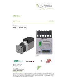
Default Value<br />
0x00000FA2 (Micro Drive)<br />
0x00000FA3 (Modula Drive)<br />
Sub-Index 003<br />
Description<br />
Revision number<br />
Contains the revision number<br />
Data Type UNSIGNED32<br />
Access RO<br />
PDO Mapping No<br />
Default Value 0x1<br />
Sub-Index 004<br />
Description Serial number<br />
Data Type UNSIGNED32<br />
Access RO<br />
PDO Mapping No<br />
Default Value 0x1<br />
www.beh.ch<br />
CANOpen Programmers Reference For AC Servo Drives· Rev. 6.7 · 16 – 142
2.4.12 Object 1600h Receive PDO Mapping Parameter 1<br />
It contains the mapping parameters of the first PDO the device is able to receive.<br />
Sub-index 0 contains the number of the mapped data objects.<br />
The structure of a mapping entry is: index (16bit), subindex (8bit),length (8bit)<br />
2.4.12.1 Object Description<br />
Index 1600h<br />
Name RPDO Mapping Parameter 1<br />
Object Code Record<br />
Number of Elements 16<br />
Data Type PDO_MAPPING<br />
Category Optional<br />
2.4.12.2 Entry Description<br />
Sub-Index 000<br />
Description Number of Entries<br />
Access RW – ALW<br />
PDO Mapping No<br />
Default Value 0x2<br />
Sub-Index 001<br />
Description Mapping Entry 1<br />
Entry Category Optional<br />
Data Type UNSIGNED32<br />
Access RW – ALW<br />
PDO Mapping No<br />
Default Value 0x60400010<br />
Lower Limit 0x0<br />
Upper Limit 0xFFFFFFFF<br />
Sub-Index 002<br />
Description Mapping Entry 2<br />
Default Value 0x607A0020<br />
Mapping Entry 2 to 16 Default Value 0 (Sub-Index 2-16)<br />
www.beh.ch<br />
CANOpen Programmers Reference For AC Servo Drives· Rev. 6.7 · 17 – 142
2.4.13 Object 1601h Receive PDO Mapping Parameter 2<br />
Sub-index 0 contains the number of the mapped data objects.<br />
The structure of a mapping entry is: index (16bit), subindex (8bit),length (8bit)<br />
2.4.13.1 Object Description<br />
Index 1601h<br />
Name RPDO Mapping Parameter 2<br />
Object Code Record<br />
Number of Elements 16<br />
Data Type PDO_MAPPING<br />
Category Optional<br />
2.4.13.2 Entry Description<br />
Sub-Index 000<br />
Description Number of Entries<br />
Access RW – ALW<br />
Default Value 0x2<br />
Sub-Index 001<br />
Description Mapping Entry 1<br />
Entry Category Optional<br />
Data Type UNSIGNED32<br />
Access RW – ALW<br />
Default Value 0x60400010<br />
Lower Limit 0x0<br />
Upper Limit 0xFFFFFFFF<br />
Sub-Index 002<br />
Description Mapping Entry 2<br />
Default Value 0x60600008<br />
Mapping Entry 3 to 16 Default Value 0 (Sub-Index 3-16)<br />
www.beh.ch<br />
CANOpen Programmers Reference For AC Servo Drives· Rev. 6.7 · 18 – 142
2.4.14 Object 1602h Receive PDO Mapping Parameter 3<br />
Sub-index 0 contains the number of the mapped data objects.<br />
The structure of a mapping entry is: index (16bit), subindex (8bit),length (8bit)<br />
2.4.14.1 Object Description<br />
Index 1602h<br />
Name RPDO Mapping Parameter 3<br />
Object Code Record<br />
Number of Elements 16<br />
Data Type PDO_MAPPING<br />
Category Optional<br />
2.4.14.2 Entry Description<br />
Sub-Index 000<br />
Description Number of Entries<br />
Access RW – ALW<br />
Default Value 0x2<br />
Sub-Index 001<br />
Description Mapping Entry 1<br />
Entry Category Optional<br />
Data Type UNSIGNED32<br />
Access RW – ALW<br />
Default Value 0x60400010<br />
Lower Limit 0x0<br />
Upper Limit 0xFFFFFFFF<br />
Sub-Index 002<br />
Description Mapping Entry 2<br />
Default Value 0x607A0020<br />
Mapping Entry 3 to 16 Default Value 0 (Sub-Index 3-16)<br />
www.beh.ch<br />
CANOpen Programmers Reference For AC Servo Drives· Rev. 6.7 · 19 – 142
2.4.15 Object 1606h Receive PDO Mapping Parameter 7<br />
Sub-index 0 contains the number of the mapped data objects.<br />
The structure of a mapping entry is: index (16bit), subindex (8bit),length (8bit)<br />
2.4.15.1 Object Description<br />
Index 1606h<br />
Name RPDO Mapping Parameter 7<br />
Object Code Record<br />
Number of Elements 16<br />
Data Type PDO_MAPPING<br />
Category Optional<br />
2.4.15.2 Entry Description<br />
Sub-Index 000<br />
Description Number of Entries<br />
Entry Category Mandatory<br />
Access RW – ALW<br />
Default Value 0x3<br />
Sub-Index 001<br />
Description Mapping Entry 1<br />
Data Type UNSIGNED32<br />
Access RW – ALW<br />
Default Value 0x21030010<br />
Lower Limit 0x0<br />
Upper Limit 0xFFFFFFFF<br />
Sub-Index 002<br />
Description Mapping Entry 2<br />
Default Value 0x2104002<br />
Sub-Index 003<br />
Description Mapping Entry 3<br />
Default Value 0x21110010<br />
Mapping Entry 4 to 16 Default Value 0 (Sub-Index 4-16)<br />
www.beh.ch<br />
CANOpen Programmers Reference For AC Servo Drives· Rev. 6.7 · 20 – 142
2.4.16 Object 1610h Receive PDO Mapping Parameter 17<br />
Sub-index 0 contains the number of the mapped data objects.<br />
The structure of a mapping entry is: index (16bit), subindex (8bit),length (8bit)<br />
2.4.16.1 Object Description<br />
Index 1610h<br />
Name RPDO Mapping Parameter 17<br />
Object Code Record<br />
Number of Elements 16<br />
Data Type PDO_MAPPING<br />
Category Optional<br />
2.4.16.2 Entry Description<br />
Sub-Index 000<br />
Description Number of Entries<br />
Access RW – ALW<br />
Default Value 0x3<br />
Sub-Index 001<br />
Description Mapping Entry 1<br />
Entry Category Optional<br />
Data Type UNSIGNED32<br />
Access RW – ALW<br />
Default Value 0x21160020<br />
Lower Limit 0x0<br />
Upper Limit 0xFFFFFFFF<br />
Sub-Index 002<br />
Description Mapping Entry 2<br />
Default Value 0x21140010<br />
Sub-Index 003<br />
Description Mapping Entry 3<br />
Default Value 0x21010410<br />
Mapping Entry 2 to 16 Default Value 0 (Sub-Index 4-16)<br />
www.beh.ch<br />
CANOpen Programmers Reference For AC Servo Drives· Rev. 6.7 · 21 – 142
2.4.17 Object 1611h Receive PDO Mapping Parameter 18<br />
Sub-index 0 contains the number of the mapped data objects.<br />
The structure of a mapping entry is: index (16bit), subindex (8bit),length (8bit)<br />
2.4.17.1 Object Description<br />
Index 1611h<br />
Name RPDO Mapping Parameter 18<br />
Object Code Record<br />
Number of Elements 16<br />
Data Type PDO_MAPPING<br />
Category Optional<br />
2.4.17.2 Entry Description<br />
Sub-Index 000<br />
Description Number of Entries<br />
Access RW – ALW<br />
Default Value 0x1<br />
Sub-Index 001<br />
Description Mapping Entry 1<br />
Entry Category Optional<br />
Data Type UNSIGNED32<br />
Access RW – ALW<br />
Default Value 0x21170020<br />
Lower Limit 0x0<br />
Upper Limit 0xFFFFFFFF<br />
Sub-Index 002<br />
Description Mapping Entry 2<br />
Default Value 0x60810020<br />
Mapping Entry 2 to 16 Default Value 0 (Sub-Index 3-16)<br />
www.beh.ch<br />
CANOpen Programmers Reference For AC Servo Drives· Rev. 6.7 · 22 – 142
2.4.18 Object 1A00h Transmit PDO Mapping Parameter 1<br />
It contains the mapping parameters of the first PDO the device is able to transmit.<br />
Sub-index 0 contains the number of the mapped data objects.<br />
The structure of a mapping entry is: index (16bit), subindex (8bit),length (8bit)<br />
2.4.18.1 Object Description<br />
Index 1A00h<br />
Name TPDO Mapping Parameter 1<br />
Object Code Record<br />
Number of Elements 16<br />
Data Type PDO_MAPPING<br />
Category Optional<br />
2.4.18.2 Entry Description<br />
Sub-Index 000<br />
Description Number of Entries<br />
Access RW – ALW<br />
Default Value 0x3<br />
Sub-Index 001<br />
Description Mapping Entry 1<br />
Entry Category Optional<br />
Data Type UNSIGNED32<br />
Access RW – ALW<br />
Default Value 0x60410010<br />
Lower Limit 0x0<br />
Upper Limit 0xFFFFFFFF<br />
Sub-Index 002<br />
Default Value 0x60640020<br />
Sub-Index 003<br />
Default Value 0x20310110<br />
Mapping Entry 4 to 16 Default Value 0 (Sub-Index 4-16)<br />
www.beh.ch<br />
CANOpen Programmers Reference For AC Servo Drives· Rev. 6.7 · 23 – 142
2.4.19 Object 1A01h Transmit PDO Mapping Parameter 2<br />
Sub-index 0 contains the number of the mapped data objects.<br />
The structure of a mapping entry is: index (16bit), subindex (8bit),length (8bit)<br />
2.4.19.1 Object Description<br />
Index 1A01h<br />
Name TPDO Mapping Parameter 2<br />
Object Code Record<br />
Number of Elements 16<br />
Data Type PDO_MAPPING<br />
Category Optional<br />
2.4.19.2 Entry Description<br />
Sub-Index 000<br />
Description Number of Entries<br />
Access RW – ALW<br />
Default Value 0x2<br />
Sub-Index 001<br />
Description Mapping Entry 1<br />
Entry Category Optional<br />
Data Type UNSIGNED32<br />
Access RW – ALW<br />
Default Value 0x60410010<br />
Lower Limit 0x0<br />
Upper Limit 0xFFFFFFFF<br />
Sub-Index 002<br />
Default Value 0x60610008<br />
Mapping Entry 3 to 16 Default Value 0 (Sub-Index 3-16)<br />
www.beh.ch<br />
CANOpen Programmers Reference For AC Servo Drives· Rev. 6.7 · 24 – 142
2.4.20 Object 1A02h Transmit PDO Mapping Parameter 3<br />
Sub-index 0 contains the number of the mapped data objects.<br />
The structure of a mapping entry is: index (16bit), subindex (8bit),length (8bit)<br />
2.4.20.1 Object Description<br />
Index 1A02h<br />
Name TPDO Mapping Parameter 3<br />
Object Code Record<br />
Number of Elements 16<br />
Data Type PDO_MAPPING<br />
Category Optional<br />
2.4.20.2 Entry Description<br />
Sub-Index 000<br />
Description Number of Entries<br />
Access RW – ALW<br />
Default Value 0x2<br />
Sub-Index 001<br />
Description Mapping Entry 1<br />
Entry Category Optional<br />
Data Type UNSIGNED32<br />
Access RW – ALW<br />
Default Value 0x60410010<br />
Lower Limit 0x0<br />
Upper Limit 0xFFFFFFFF<br />
Sub-Index 002<br />
Description Mapping Entry 2<br />
Default Value 0x60640020<br />
Mapping Entry 3 to 16 Default Value 0 (Sub-Index 3-16)<br />
www.beh.ch<br />
CANOpen Programmers Reference For AC Servo Drives· Rev. 6.7 · 25 – 142
2.4.21 Object 1A06h Transmit PDO Mapping Parameter 7<br />
Sub-index 0 contains the number of the mapped data objects.<br />
The structure of a mapping entry is: index (16bit), subindex (8bit),length (8bit)<br />
2.4.21.1 Object Description<br />
Index 1A06h<br />
Name TPDO Mapping Parameter 7<br />
Object Code Record<br />
Number of Elements 16<br />
Data Type PDO_MAPPING<br />
Category Optional<br />
2.4.21.2 Entry Description<br />
Sub-Index 000<br />
Description Number of Entries<br />
Access RW – ALW<br />
Default Value 0x2<br />
Sub-Index 001<br />
Description Mapping Entry 1<br />
Entry Category Optional<br />
Data Type UNSIGNED32<br />
Access RW – ALW<br />
Default Value 0x60410010<br />
Lower Limit 0x0<br />
Upper Limit 0xFFFFFFFF<br />
Sub-Index 002<br />
Description Mapping Entry 2<br />
Default Value 0x60440010<br />
Mapping Entry 3 to 16 Default Value 0 (Sub-Index 3-16)<br />
www.beh.ch<br />
CANOpen Programmers Reference For AC Servo Drives· Rev. 6.7 · 26 – 142
2.4.22 Object 1A10h Transmit PDO Mapping Parameter 17<br />
Sub-index 0 contains the number of the mapped data objects.<br />
The structure of a mapping entry is: index (16bit), subindex (8bit),length (8bit)<br />
2.4.22.1 Object Description<br />
Index 1A10h<br />
Name TPDO Mapping Parameter 17<br />
Object Code Record<br />
Number of Elements 16<br />
Data Type PDO_MAPPING<br />
Category Optional<br />
2.4.22.2 Entry Description<br />
Sub-Index 000<br />
Description Number of Entries<br />
Access RW – ALW<br />
Default Value 0x1<br />
Sub-Index 001<br />
Description Mapping Entry 1<br />
Entry Category Optional<br />
Data Type UNSIGNED32<br />
Access RW – ALW<br />
Default Value 0x20310110<br />
Lower Limit 0x0<br />
Upper Limit 0xFFFFFFFF<br />
Mapping Entry 2 to 16 Default Value 0 (Sub-Index 2-16)<br />
2.4.23 Object 1A11h Transmit PDO Mapping Parameter 18<br />
Sub-index 0 contains the number of the mapped data objects.<br />
The structure of a mapping entry is: index (16bit), subindex (8bit),length (8bit)<br />
2.4.23.1 Object Description<br />
Index 1A11h<br />
Name TPDO Mapping Parameter 18<br />
Object Code Record<br />
Number of Elements 16<br />
Data Type PDO_MAPPING<br />
Category Optional<br />
2.4.23.2 Entry Description<br />
Sub-Index 000<br />
Description Number of Entries<br />
Access RW – ALW<br />
Default Value 0x0<br />
Mapping Entry 1 to 16 Default Value 0 (Sub-Index 1-16)<br />
www.beh.ch<br />
CANOpen Programmers Reference For AC Servo Drives· Rev. 6.7 · 27 – 142
2.5 Can Communication profile objects<br />
Used only in devices with CANbus<br />
2.5.1 Object 1005h COB-ID SYNC<br />
COB-ID of the Synchronization object. The device generates a SYNC message if bit 30 is set.<br />
The meaning of other bits is equal to the other communication objects.<br />
2.5.1.1 Object Description<br />
Index 1005h<br />
Name COB-ID SYNC<br />
Object Code Variable<br />
Data Type UNSIGNED32<br />
Category Optional<br />
2.5.1.2 Entry Description<br />
Access RW – ALW<br />
PDO Mapping No<br />
Default Value 0x80000080<br />
Lower Limit 0x00000000<br />
Upper Limit 0xFFFFFFFF<br />
2.5.2 Object 1006h Communication Cycle Period<br />
This entry defines the communication cycle period in us. It is 0, if not used.<br />
2.5.2.1 Object Description<br />
Index 1005h<br />
Name Communication Cycle Period<br />
Object Code Variable<br />
Data Type UNSIGNED32<br />
Category Optional<br />
2.5.2.2 Entry Description<br />
Access RW – ALW<br />
PDO Mapping No<br />
Default Value 0x00002710<br />
Lower Limit 0x00000000<br />
Upper Limit 0xFFFFFFFF<br />
www.beh.ch<br />
CANOpen Programmers Reference For AC Servo Drives· Rev. 6.7 · 28 – 142
2.5.3 Object 1007h Synchronous Window Length<br />
It contains the length of the time window for synchronous messages in us. It is 0, if not used.<br />
2.5.3.1 Object Description<br />
Index 1007h<br />
Name Synchronous Window Lenght<br />
Object Code Variable<br />
Data Type UNSIGNED32<br />
Category Optional<br />
2.5.3.2 Entry Description<br />
Access RW – ALW<br />
PDO Mapping No<br />
Default Value 0x00000000<br />
Lower Limit 0x00000000<br />
Upper Limit 0xFFFFFFFF<br />
Unit us<br />
2.5.4 Object 1014h COB-ID EMCY<br />
COB-ID used for emergency message (Emergency Server).<br />
2.5.4.1 Object Description<br />
Index 1014h<br />
Name COB-ID EMCY<br />
Object Code Variable<br />
Data Type UNSIGNED32<br />
Category Optional<br />
2.5.4.2 Entry Description<br />
Access RO<br />
PDO Mapping No<br />
Default Value 0x00000080<br />
Lower Limit 0x00000001<br />
Upper Limit 0xFFFFFFFF<br />
Unit<br />
www.beh.ch<br />
CANOpen Programmers Reference For AC Servo Drives· Rev. 6.7 · 29 – 142
2.5.5 Object 1016h Heartbeat Consumer Entries<br />
The consumer heartbeat time defines the expected heartbeat cycle<br />
time and thus has to be higher than the corresponding producer heartbeat<br />
time configured on the device producing this heartbeat.<br />
The bits 31 - 24 of each sub-index has to be 0.<br />
The bits 23 - 16 contain the node-id.<br />
The lower 16 bits contain the heartbeat time.<br />
2.5.5.1 Object Description<br />
Index 1016h<br />
Name Heartbeat Consumer Entries<br />
Object Code Array<br />
Number of Elements 2<br />
Data Type UNSIGNED32<br />
Category Optional<br />
2.5.5.2 Entry Description<br />
Sub-Index 001-002<br />
Description Consumer Heartbeat Time 1 / 2<br />
Data Type UNSIGNED32<br />
Access RW – ALW (SNVM)<br />
PDO Mapping No<br />
Default Value 1:0x000203E8 / 2: 0<br />
Lower Limit 0x0<br />
Upper Limit 0xFFFFFFFF<br />
2.5.6 Object 1017h Producer Heartbeat Time<br />
The producer heartbeat time defines the cycle time of the heartbeat. If the time is 0<br />
it is not used. The time has to be a multiple of 1 msec<br />
2.5.6.1 Object Description<br />
Index 1017h<br />
Name Producer Heartbeat Time<br />
Object Code Variable<br />
Data Type UNSIGNED16<br />
Category Optional<br />
2.5.6.2 Entry Description<br />
Access RW - ALW (SNVM)<br />
PDO Mapping No<br />
Default Value 0x0<br />
Lower Limit 0x0<br />
Upper Limit 0xFFFF<br />
Unit ms<br />
www.beh.ch<br />
CANOpen Programmers Reference For AC Servo Drives· Rev. 6.7 · 30 – 142
2.5.7 Object 1400h-1402 / 1406h / 1410h / 1411h Receive PDO Com. Parameter<br />
It contains the communicaion parameters of the PDOs the device is able to receive.<br />
See /2/ for a detailed description.<br />
2.5.7.1 Object Description<br />
Index 1400h-1402h / 1406h / 1410h / 1411h<br />
Name Receive PDO Communication Parameters<br />
Object Code Record<br />
Number of Elements 3<br />
Data Type PDO_COMM_PAR<br />
Category Optional<br />
2.5.7.2 Entry Description<br />
Sub-Index 001<br />
Description<br />
COB-ID<br />
If bit 31 is set the PDO is disabled.<br />
Entry Category Optional<br />
Data Type UNSIGNED32<br />
Access RW – ALW<br />
PDO Mapping No<br />
Default Value 0x80000000<br />
Lower Limit 0x1<br />
Upper Limit 0xFFFFFFFF<br />
Sub-Index 002<br />
Description Transmission Type<br />
Entry Category Optional<br />
Data Type UNSIGNED8<br />
Access RW – ALW<br />
PDO Mapping No<br />
0xFE<br />
1-240 Synchronous<br />
Default Value<br />
254 Asynchronous<br />
1410h: 1<br />
Lower Limit 0x0<br />
Upper Limit 0xFF<br />
Sub-Index 003<br />
Description Inhibit Time<br />
Entry Category Optional<br />
Data Type UNSIGNED16<br />
Access RW – ALW<br />
PDO Mapping No<br />
Default Value 0x0<br />
Lower Limit 0x0<br />
Upper Limit 0xFFFF<br />
Unit 100 us<br />
www.beh.ch<br />
CANOpen Programmers Reference For AC Servo Drives· Rev. 6.7 · 31 – 142
2.5.8 Object 1800h-1802h / 1806 / 1810h / 1811h Transmit PDO Com. Parameter<br />
It contains the communicaion parameters of the PDOs the device is able to transmit.<br />
See /2/ and /3/ for a detailed description.<br />
2.5.8.1 Object Description<br />
Index 1800h-1802h / 1806h / 1810h /1811h<br />
Name TPDO Communication Para.<br />
Object Code Record<br />
Number of Elements 6<br />
Data Type PDO_COMM_PAR<br />
PDO Mapping No<br />
Category Optional<br />
2.5.8.2 Entry Description<br />
Sub-Index 001<br />
Description COB-ID<br />
Entry Category Optional<br />
Data Type UNSIGNED32<br />
Access RW – ALW<br />
Default Value 0x80000000<br />
Lower Limit 0x1<br />
Upper Limit 0xFFFFFFFF<br />
Sub-Index 002<br />
Description Transmission Type<br />
Entry Category Optional<br />
Data Type UNSIGNED8<br />
Access RW – ALW<br />
Default Value 0xFE<br />
Lower Limit 0x0<br />
Upper Limit 0xFF<br />
Sub-Index 003<br />
Description Inhibit Time<br />
Entry Category Optional<br />
Data Type UNSIGNED16<br />
Access RW – ALW<br />
Default Value 0x0 / 1806h: 5 / 1810h: 5000 / 1811h: 5000<br />
Lower Limit 0x0<br />
Upper Limit 0xFFFF<br />
Unit 100 us<br />
Sub-Index 005<br />
Description Event Timer<br />
Entry Category Optional<br />
Data Type UNSIGNED16<br />
Access RW – ALW<br />
Default Value 0x0<br />
Lower Limit 0x0<br />
Upper Limit 0xFFFF<br />
Unit ms<br />
www.beh.ch<br />
CANOpen Programmers Reference For AC Servo Drives· Rev. 6.7 · 32 – 142
2.6 Ethercat Communication profile objects<br />
Used only in devices with ethercat<br />
2.6.1 EtherCAT- Interface<br />
This device is an EtherCAT slave according EtherCAT Slave Device Description<br />
2.6.2 EtherCAT-specific communication<br />
This communication is in the EtherCAT specification. The supported features can be found<br />
in the Device Descripton Data (. XML).<br />
2.6.3 Device-specific communication<br />
To configure the device-specific functions and for the transfer of user data, the<br />
"CANopen over EtherCAT (CoE) is used.<br />
2.6.4 Object 1C00h Sync Manager Communication Type<br />
Subindex (1-4) defines communication type of the corresponding Sync Manager channel<br />
0=unused<br />
1=mailbox out (MS)<br />
2=mailbox in (SM)<br />
3=process data out (RxPDO)<br />
4=process data in (TxPDO)<br />
2.6.4.1 Object Description<br />
Index 1C00h<br />
Name Sync Manager Communication Type<br />
Object Code Array<br />
Number of Elements 4<br />
Data Type UNSIGNED32<br />
PDO Mapping No<br />
Category Optional<br />
2.6.4.2 Entry Description<br />
Sub-Index 001<br />
Description Communication Type 1<br />
Access RO<br />
Default Value 1<br />
Sub-Index 002<br />
Description Communication Type 2<br />
Access RO<br />
Default Value 2<br />
Sub-Index 002<br />
Description Communication Type 2<br />
Access RO<br />
Default Value 3<br />
Sub-Index 003<br />
Description Communication Type 4<br />
Access RO<br />
Default Value 4<br />
www.beh.ch<br />
CANOpen Programmers Reference For AC Servo Drives· Rev. 6.7 · 33 – 142
2.6.5 Object 1C12h Sync Manager RX PDO Assignment<br />
Assigned RX PDO in Subindex 1 to n describe the process data parts of the Sync Manager channel<br />
2.6.5.1 Object Description<br />
Index 1C12h<br />
Name Sync Manager RX PDO Assignment<br />
Object Code Array<br />
Number of Elements 9<br />
Data Type UNSIGNED16<br />
PDO Mapping No<br />
Category Optional<br />
2.6.5.2 Entry Description<br />
Sub-Index 001-009<br />
Description PDO1-PDO9<br />
Access RW – ALW<br />
Default Value 0x1600-0x1606 /0x1610 / 0x1611<br />
2.6.6 Object 1C13h Sync Manager TX PDO Assignment<br />
Assigned TX PDO in Subindex 1 to n describe the process data parts of the Sync Manager channel<br />
2.6.6.1 Object Description<br />
Index 1C13h<br />
Name Sync Manager TX PDO Assignment<br />
Object Code Array<br />
Number of Elements 9<br />
Data Type UNSIGNED16<br />
PDO Mapping No<br />
Category Optional<br />
2.6.6.2 Entry Description<br />
Sub-Index 001-009<br />
Description PDO1-PDO9<br />
Access RW – ALW<br />
Default Value 0x+A00-0x1A06 /0x1A10 / 0x1A11<br />
www.beh.ch<br />
CANOpen Programmers Reference For AC Servo Drives· Rev. 6.7 · 34 – 142
2.6.7 1C32h Sync Manager Output Parameter<br />
Sync Manager Pasrameter<br />
2.6.7.1 Object Description<br />
Index 1C32h<br />
Name Sync Manager Output Parameter<br />
Object Code Array<br />
Number of Elements 9<br />
Data Type RECORD<br />
PDO Mapping No<br />
Category Optional<br />
www.beh.ch<br />
2.6.7.2 Entry Description<br />
Sub-Index 001<br />
Sync Mode<br />
Description<br />
0: Not synchronized<br />
1: Synchron –synchronized with AL Event on this Sync Ma.<br />
2: DC Sync0 –synchronized with AL Event Sync0<br />
3: DC Sync1 –synchronized with AL Event Sync1<br />
0x20+n: SyncSM(n) synchronized with all Event of SM(n)<br />
Data Type UNSIGNED16<br />
Access RW – ALW<br />
Default Value 0x1 (SYNCTYPE_SYNCHRON)<br />
Lower Limit 0x0<br />
Upper Limit 0xFFFF<br />
Sub-Index 002<br />
Description<br />
Cycle Time<br />
Time between two events in ns<br />
Data Type UNSIGNED32<br />
Access RO<br />
Default Value 0x0<br />
Lower Limit 0x0<br />
Upper Limit 0xFFFFFFFF<br />
Sub-Index 003<br />
Description<br />
Shift Time<br />
Only important for DC Mode: Contains the Time Shift between<br />
the SYNC0 (SYNC1) Signal and when the Outputs are put to<br />
the Hardware to allow the Master a very exact Calculation of<br />
Delay Times<br />
Data Type UNSIGNED32<br />
Access RO<br />
Default Value 0x0<br />
Sub-Index 004<br />
Description<br />
Sync Mode Supported<br />
conatins the supported Synchronization Types<br />
Data Type UNSIGNED32<br />
Access RO<br />
Default Value 0x4003<br />
CANOpen Programmers Reference For AC Servo Drives· Rev. 6.7 · 35 – 142
www.beh.ch<br />
Sub-Index 005<br />
Minimum cycle time<br />
Description<br />
Contains the minimum Cycle Time the Slave is able to<br />
support It will be calculated dynamically, because it depends<br />
on the connected Modules<br />
Data Type UNSIGNED32<br />
Access RO<br />
Default Value 0x0<br />
Sub-Index 006<br />
Calc and copy time<br />
Only for DC Mode important: Contains the minimum Delay<br />
Time the Slave needs after receiving the SM2-Event before<br />
Description<br />
the SYNC0 (SYNC1) can be received without Delays. It will be<br />
calculated dynamically because it depends on the connected<br />
Modules<br />
Data Type UNSIGNED32<br />
Access RO<br />
Default Value 0x0<br />
Sub-Index 007-032<br />
Description Reserve<br />
2.6.8 1C33h Sync Manager Input Parameter<br />
Same as 1C32h Sync Manager Output Parameter see above<br />
CANOpen Programmers Reference For AC Servo Drives· Rev. 6.7 · 36 – 142
3 Drive Profile Objects<br />
3.1 Common<br />
3.1.1 Object 6402h Motor Type<br />
The type of motor connected with the controller<br />
3.1.1.1 Object Description<br />
Index 6402h<br />
Name Motor Type<br />
Object Code Variable<br />
Data Type UNSIGNED16<br />
Category Optional<br />
3.1.1.2 Entry Description<br />
Access RW - ALW (SNVM)<br />
PDO Mapping No<br />
Default Value 0x3<br />
Lower Limit 0x3<br />
Upper Limit 0x3<br />
Only PM synchronous motor is supported<br />
3.1.2 Object 6502h Supported Drive Modes<br />
This object documents all operational modes which are supported by the drive.<br />
Bit 31-16 = manufacturer specific<br />
Bit 15-07 = reserved<br />
Bit 6 = ip<br />
Bit 5 = hm<br />
Bit 4 = reserved<br />
Bit 3 = tq<br />
Bit 2 = pv<br />
Bit 1 = vl<br />
Bit 0 = pp<br />
3.1.2.1 Object Description<br />
Index 6502h<br />
Name Supported Drive Modes<br />
Object Code Variable<br />
Data Type UNSIGNED32<br />
Category Optional<br />
3.1.2.2 Entry Description<br />
Access RO<br />
PDO Mapping No<br />
Default Value 0x1006D<br />
Lower Limit 0x0<br />
Upper Limit 0xFFFFFFFF<br />
www.beh.ch<br />
CANOpen Programmers Reference For AC Servo Drives· Rev. 6.7 · 37 – 142
3.1.3 Object 2001h Error Code Memory<br />
Store the last 4 errors in non-volatile memory. See also chapter 2.4.4.3 (Error Codes)<br />
3.1.3.1 Object Description<br />
Index 2001h<br />
Name Error Code Memory<br />
Object Code Array<br />
Number of Elements 4<br />
Data Type UNSIGNED16<br />
Category Manufacturer specific<br />
3.1.3.2 Entry Description<br />
Sub-Index 001-04<br />
Description Error Code<br />
Access RO – ALW (SNVM)<br />
PDO Mapping No<br />
Default Value 0<br />
Lower Limit 0x0<br />
Upper Limit 0xFFFF<br />
Unit<br />
3.1.4 Object 2010h Chopper Settings<br />
Settings for internal chopper resistance<br />
3.1.4.1 Object Description<br />
Index 2010h<br />
Name Chopper Settings<br />
Object Code Array<br />
Number of Elements 2<br />
Data Type UNSIGNED16<br />
Category Manufacturer specific<br />
3.1.4.2 Entry Description<br />
Sub-Index 001<br />
Description Enable / Disable<br />
Access RW – ALW (SNVM)<br />
PDO Mapping No<br />
Default Value 0<br />
Lower Limit 0x0<br />
Upper Limit 0x1<br />
Unit ON / OFF<br />
Sub-Index 002<br />
Description<br />
Chopper On Voltage<br />
DC Link Voltage (when Link Voltage is over that value<br />
Chopper resistance is switched on )<br />
Access RW – ALW (SNVM)<br />
PDO Mapping No<br />
Default Value 3300 (330VDC)<br />
Lower Limit 2000 (200VDC)<br />
Upper Limit 4000<br />
Unit 100mV<br />
www.beh.ch<br />
CANOpen Programmers Reference For AC Servo Drives· Rev. 6.7 · 38 – 142
3.1.5 Object 2015h-2019h Cam Controller<br />
Settings for internal cam controller<br />
If actual position > On Position (Sub-index1) and < Off Position (Sub-index2) Status=1 otherwise<br />
Status=0<br />
Sub-index4: Select Output 1-4 if Status==1 Output=On<br />
3.1.5.1 Object Description<br />
Index 2015h-2019h<br />
Name Cam Controllers<br />
Object Code Array<br />
Number of Elements 3<br />
Data Type UNSIGNED32<br />
Category Manufacturer specific<br />
3.1.5.2 Entry Description<br />
Sub-Index 001<br />
Description On Position<br />
Access RW – ALW (SNVM)<br />
PDO Mapping No<br />
Default Value 0<br />
Lower Limit 0x80000000<br />
Upper Limit 0x7FFFFFFF<br />
Unit user<br />
Sub-Index 002<br />
Description Off Position<br />
Access RW – ALW (SNVM)<br />
PDO Mapping No<br />
Default Value 0<br />
Lower Limit 0x80000000<br />
Upper Limit 0x7FFFFFFF<br />
Unit user<br />
Sub-Index 003<br />
Description Status<br />
Access RO<br />
PDO Mapping YES<br />
Default Value 0<br />
Lower Limit 0x0<br />
Upper Limit 0x1<br />
Sub-Index 004<br />
Description Outputmapping<br />
Access RW – ALW<br />
PDO Mapping No<br />
Default Value 0<br />
Lower Limit 0x0<br />
Upper Limit 0x1<br />
www.beh.ch<br />
CANOpen Programmers Reference For AC Servo Drives· Rev. 6.7 · 39 – 142
3.1.6 Object 2020h Resolver Settings<br />
3.1.6.1 Object Description<br />
Index 2020h<br />
Name Resolver Settings<br />
Object Code Record<br />
Number of Elements 5<br />
Data Type RESOLVER<br />
Category Manufacturer specific<br />
3.1.6.2 Entry Description<br />
Sub-Index 001<br />
Description Reserve<br />
Sub-Index 002<br />
Description Resolver pos<br />
Data Type UNSIGNED16<br />
Access RO<br />
PDO Mapping No<br />
Default Value 0<br />
Sub-Index 003<br />
Description Resolver dir (Resolver actual direction)<br />
Data Type UNSIGNED8<br />
Access RO<br />
PDO Mapping No<br />
Default Value 0<br />
Sub-Index 004<br />
Description Resolver error on off (Switch off Errors from Resolver)<br />
Data Type UNSIGNED8<br />
Access RW – ALW (SNVM)<br />
PDO Mapping No<br />
Default Value 0<br />
Lower Limit 0x0<br />
Upper Limit 0xFF<br />
www.beh.ch<br />
Sub-Index 005<br />
Description<br />
Resolver frequency<br />
Resolver Frequency 0=10kHz / 1=12kHz / 2=15kHz / 3=20kHz<br />
Data Type UNSIGNED8<br />
Access RW – ALW (SNVM)<br />
PDO Mapping No<br />
Default Value 0<br />
Lower Limit 0x0<br />
Upper Limit 0x3<br />
CANOpen Programmers Reference For AC Servo Drives· Rev. 6.7 · 40 – 142
3.1.7 Object 2021h Drive State<br />
Drive Status information for debug purpose<br />
Bit1: Task Stop move<br />
Bit2: Motor Position in Window<br />
Bit3: Motor Position Overload<br />
Bit4: Max Current reached<br />
Bit5: Nom Current reached<br />
Bit6: Resolver Error<br />
Bit7: Ip mode speed max reached<br />
3.1.7.1 Object Description<br />
Index 2021h<br />
Name Drive State<br />
Object Code Variable<br />
Data Type UNSIGNED16<br />
Category Manufacturer specific<br />
3.1.7.2 Entry Description<br />
Access RO<br />
PDO Mapping YES<br />
Default Value 0x0<br />
Lower Limit 0x0<br />
Upper Limit 0xFFFF<br />
3.1.8 Object 2022h Space Vector<br />
Enable/Disable Space Vector Modulation<br />
3.1.8.1 Object Description<br />
Index 2022h<br />
Name Space Vector<br />
Object Code Variable<br />
Data Type UNSIGNED8<br />
Category Optional<br />
3.1.8.2 Entry Description<br />
Access RW – ALW (SNVM)<br />
PDO Mapping No<br />
Default Value 0x1 (Enable)<br />
Lower Limit 0x0<br />
Upper Limit 0x1<br />
www.beh.ch<br />
CANOpen Programmers Reference For AC Servo Drives· Rev. 6.7 · 41 – 142
3.1.9 Object 2023h Safety<br />
Safety Input Settings<br />
3.1.9.1 Object Description<br />
Index 2023h<br />
Name Safety<br />
Object Code Array<br />
Number of Elements 2<br />
Data Type UNSIGNED16<br />
Category Manufacturer specific<br />
3.1.9.2 Entry Description<br />
Sub-Index 001<br />
Description Safety Off Time. Delay between Input and Safety Off<br />
Access RW – ALW (SNVM)<br />
PDO Mapping NO<br />
Default Value 0<br />
Lower Limit 0x0<br />
Upper Limit 0xFFFF<br />
Unit ms<br />
Sub-Index 002<br />
Description<br />
Safety Input. Safety Input (When 0 Safety = Off)<br />
Input On Drive Stop (Halt Option Code)<br />
Access RW – ALW (SNVM)<br />
PDO Mapping NO<br />
Default Value 0<br />
Lower Limit 0x8000<br />
Upper Limit 0x7FFF<br />
Unit Select Input 1-8<br />
3.1.10 Object 2030h ADC Channels<br />
ADC Channel Monitor for debug purpose<br />
3.1.10.1 Object Description<br />
Index 2030h<br />
Name ADC Channels<br />
Object Code Array<br />
Number of Elements 16<br />
Data Type INTEGER16<br />
Category Manufacturer specific<br />
3.1.10.2 Entry Description<br />
Sub-Index 001-016<br />
Description ADC0-ADC15<br />
Access RO<br />
PDO Mapping No<br />
Default Value 0<br />
Lower Limit 0x8000<br />
Upper Limit 0x7FFF<br />
www.beh.ch<br />
CANOpen Programmers Reference For AC Servo Drives· Rev. 6.7 · 42 – 142
3.1.11 Object 2031h Temperatur Monitor<br />
Display temperatures<br />
3.1.11.1 Object Description<br />
Index 2031h<br />
Name Temperature Monitor<br />
Object Code Array<br />
Number of Elements 2<br />
Data Type INTEGER16<br />
Category Manufacturer specific<br />
3.1.11.2 Entry Description<br />
Sub-Index 001<br />
Description Drive Temperature<br />
Access RO<br />
PDO Mapping YES<br />
Default Value 0<br />
Lower Limit 0x8000<br />
Upper Limit 0x7FFF<br />
Unit °C<br />
Sub-Index 002<br />
Description Motor Temperature (if supported on Motor)<br />
Access RO<br />
PDO Mapping YES<br />
Default Value 0<br />
Lower Limit 0x8000<br />
Upper Limit 0x7FFF<br />
Unit specific<br />
www.beh.ch<br />
CANOpen Programmers Reference For AC Servo Drives· Rev. 6.7 · 43 – 142
3.1.12 Object 2032h Voltage Monitor<br />
Shows the voltage of internal power supply for debug purpose<br />
3.1.12.1 Object Description<br />
Index 2032h<br />
Name Voltage Monitor<br />
Object Code Array<br />
Number of Elements 8<br />
Data Type INTEGER16<br />
Category Manufacturer specific<br />
3.1.12.2 Entry Description<br />
Sub-Index 001<br />
Description Max Link Voltage<br />
Access RO<br />
PDO Mapping No<br />
Default Value 0<br />
Lower Limit 0x8000<br />
Upper Limit 0x7FFF<br />
Unit 1/10V<br />
Sub-Index 002<br />
Description Min Link Voltage<br />
Unit 1/10V<br />
Sub-Index 003<br />
Description Link Voltage<br />
Unit 1/10V<br />
Sub-Index 004<br />
Description 24V Supply Voltage<br />
Unit 10mV<br />
Sub-Index 005<br />
Description 5V Supply Voltage<br />
Unit mV<br />
Sub-Index 006<br />
Description 3.3V Supply Voltage<br />
Unit mV<br />
Sub-Index 007<br />
Description 1.9V Supply Voltage<br />
Unit mV<br />
Sub-Index 008<br />
Description 1V Supply Voltage<br />
Unit mV<br />
www.beh.ch<br />
CANOpen Programmers Reference For AC Servo Drives· Rev. 6.7 · 44 – 142
3.1.13 Object 2033h Debug Monitor<br />
Only for debug purpose<br />
3.1.13.1 Object Description<br />
Index 2033h<br />
Name Debug Monitor<br />
Object Code Array<br />
Number of Elements 8<br />
Data Type INTEGER16<br />
Category Manufacturer specific<br />
3.1.13.2 Entry Description<br />
Sub-Index 001-008<br />
Description Debug0-Debug7<br />
Access RO<br />
PDO Mapping Yes<br />
Default Value 0<br />
Lower Limit 0x8000<br />
Upper Limit 0x7FFF<br />
3.1.14 Object 2035h Profile Curve<br />
Only for debug purpose<br />
3.1.14.1 Object Description<br />
Index 2035h<br />
Name Profile Curve<br />
Object Code Array<br />
Data Type DOMAIN<br />
Number of Elements 4<br />
Category Manufacturer specific<br />
3.1.14.2 Entry Description<br />
Sub-Index 001-004<br />
Description Profile Curve 0-3<br />
Entry Category Optional<br />
Data Type DOMAIN<br />
Access RW<br />
PDO Mapping No<br />
Default Value 0x0<br />
www.beh.ch<br />
CANOpen Programmers Reference For AC Servo Drives· Rev. 6.7 · 45 – 142
3.1.15 Object 2036h ANIN0<br />
Analog Input0 (see also Object 2086h Analog In Settings)<br />
3.1.15.1 Object Description<br />
Index 2036h<br />
Name ANIN0<br />
Object Code Variable<br />
Data Type INTEGER32<br />
Category Manufacturer specific<br />
3.1.15.2 Entry Description<br />
Access RO<br />
PDO Mapping YES<br />
Default Value 0x0<br />
Lower Limit 0x80000000<br />
Upper Limit 0x7FFFFFFF<br />
Unit User<br />
3.1.16 Obhect 2037h ANIN0 Filter<br />
Average Filter Settings for ANIN0. Drive must be reboot after change.<br />
3.1.16.1 Object Description<br />
Index 2037h<br />
Name ANIN0 Filter<br />
Object Code Variable<br />
Data Type UNSIGNED8<br />
Category Manufacturer specific<br />
3.1.16.2 Entry Description<br />
Access RW – ALW (SNVM)<br />
PDO Mapping NO<br />
Default Value 0x5<br />
Lower Limit 0x2<br />
Upper Limit 0x64<br />
Unit 100us<br />
3.1.17 Object 2043h Velocity Demand<br />
This object is the actual velocity provided by the profile generator scaled to Internal unit.<br />
3.1.17.1 Object Description<br />
Index 2043h<br />
Name Velocity Demand<br />
Object Code Variable<br />
Data Type INTEGER32<br />
Category Manufacturer specific<br />
3.1.17.2 Entry Description<br />
Access RO<br />
PDO Mapping NO<br />
Default Value<br />
Lower Limit 0x80000000<br />
Upper Limit 0xFFFFFFFF<br />
Unit internal<br />
www.beh.ch<br />
CANOpen Programmers Reference For AC Servo Drives· Rev. 6.7 · 46 – 142
3.1.18 Object 2040h Motor Temperature Options<br />
Settings for Motor Temperature Sensor<br />
3.1.18.1 Object Description<br />
Index 2040h<br />
Name Motor Temperature Options<br />
Object Code Array<br />
Data Type UNSIGNED16<br />
Number of Elements 3<br />
Category Manufacturer specific<br />
3.1.18.2 Entry Description<br />
Sub-Index 001<br />
Description<br />
Motor Overtemperature Monitoring<br />
Switch ON/OFF motor temperature monitoring<br />
Access RW – ALW (SNVM)<br />
PDO Mapping No<br />
Default Value 0 (OFF) 1=ON<br />
Lower Limit 0x0<br />
Upper Limit 0x1<br />
Sub-Index 002<br />
Description<br />
Switch On threshold<br />
Switch On threshold Motor Overtemperature<br />
Access RW – ALW (SNVM)<br />
PDO Mapping NO<br />
Default Value 0xBB8<br />
Lower Limit 0x0<br />
Upper Limit 0x1000<br />
Unit 12Bit (ADC)<br />
Sub-Index 003<br />
Description<br />
Switch Off threshold<br />
Switch Off threshold Motor Overtemperature<br />
Access RW – ALW (SNVM)<br />
PDO Mapping NO<br />
Default Value 0x7D0<br />
Lower Limit 0x0<br />
Upper Limit 0x1000<br />
Unit 12Bit (ADC)<br />
www.beh.ch<br />
CANOpen Programmers Reference For AC Servo Drives· Rev. 6.7 · 47 – 142
3.1.19 Object 2045h Actual Motor speed<br />
This object is the actual motor speed in rpm.<br />
3.1.19.1 Object Description<br />
Index 2045h<br />
Name Actual Motor speed<br />
Object Code Variable<br />
Data Type INTEGER32<br />
Category Manufacturer specific<br />
3.1.19.2 Entry Description<br />
Access RO<br />
PDO Mapping NO<br />
Default Value<br />
Lower Limit 0x80000000<br />
Upper Limit 0xFFFFFFFF<br />
Unit Rpm<br />
3.1.20 Object 2053h Ethercat Cycle<br />
Parameters for realtime measurment of ethercat system<br />
3.1.20.1 Object Description<br />
Index 2053h<br />
Name Ethercat Cycle<br />
Object Code Array<br />
Data Type UNSIGNED16<br />
PDO Mapping No<br />
Number of Elements 3<br />
Category Manufacturer specific<br />
3.1.20.2 Entry Description<br />
Sub-Index 001<br />
Description Enable Check<br />
Access RW – ALW<br />
Default Value 0 (OFF) 1=ON Cycle Check is running<br />
Lower Limit 0x0<br />
Upper Limit 0x1<br />
Sub-Index 002<br />
Description Actual Latency<br />
Access RO – ALW<br />
Default Value 0x0<br />
Lower Limit 0x0<br />
Upper Limit 0x7FFFFFFF<br />
Unit us<br />
Sub-Index 003<br />
Description<br />
Maximum Latency (over the measurment time)<br />
Reset value by writing<br />
Access RW – ALW<br />
Default Value 0x0<br />
Lower Limit 0x0<br />
Upper Limit 0x7FFFFFFF<br />
Unit us<br />
www.beh.ch<br />
CANOpen Programmers Reference For AC Servo Drives· Rev. 6.7 · 48 – 142
Sub-Index 004<br />
Description<br />
Minimum Latency (over the measurment time)<br />
Reset value by writing<br />
Access RW – ALW<br />
Default Value 0x0<br />
Lower Limit 0x0<br />
Upper Limit 0x7FFFFFFF<br />
Unit us<br />
Sub-Index 005<br />
Description Ist Cycle (actual cycle time)<br />
Access RO – ALW<br />
Default Value 0x0<br />
Lower Limit 0x0<br />
Upper Limit 0x7FFFFFFF<br />
Unit us<br />
Sub-Index 006<br />
Description Master Cycle (Referenz Cycle)<br />
Access RW – ALW<br />
Default Value 0x0<br />
Lower Limit 0x0<br />
Upper Limit 0x7FFFFFFF<br />
Unit us<br />
3.1.21 Object 2060h Motor Max Current Time<br />
Time the motorcurrent can be on Max Current (6073h) after the current<br />
fall down to Motor Rated Current (6075h)<br />
3.1.21.1 Object Description<br />
Index 2060h<br />
Name Motor Max Current Time<br />
Object Code Variable<br />
Data Type UNSIGNED16<br />
Category Manufacturer specific<br />
3.1.21.2 Entry Description<br />
Access RW – ALW (SNVM)<br />
PDO Mapping NO<br />
Default Value 0xA<br />
Lower Limit 0x0<br />
Upper Limit 0xFFFF<br />
Unit s<br />
www.beh.ch<br />
CANOpen Programmers Reference For AC Servo Drives· Rev. 6.7 · 49 – 142
3.1.22 Object 2061h ISR Flux Torq<br />
Flux Torq Regulator. All Values in IQ16 Format<br />
Example: Data=2.5000<br />
DataSend= 2.5*0xFFFF=163837<br />
3.1.22.1 Object Description<br />
Index 2061h<br />
Name ISR Flux Torq<br />
Object Code Array<br />
Number of Elements 0xE<br />
Data Type UNSIGNED32 (iq16)<br />
Category Manufacturer specific<br />
3.1.22.2 Entry Description<br />
Sub-Index 001<br />
Description mot_res<br />
Access RW – ALW (SNVM)<br />
PDO Mapping No<br />
Default Value 0x00020000<br />
Lower Limit 0x00000000<br />
Upper Limit 0xFFFFFFFF<br />
Sub-Index 002<br />
Description Offs_Ang<br />
Default Value 0x3FFE<br />
Sub-Index 003<br />
Description Flux_Kp<br />
Default Value 0x0<br />
Sub-Index 004<br />
Description Flux_Ki<br />
Default Value 0x0<br />
Sub-Index 005<br />
Description Flux_Kc<br />
Default Value 0x0<br />
Sub-Index 006<br />
Description Flux_Kd<br />
Default Value 0x0<br />
Sub-Index 007<br />
Description Flux_phase<br />
Default Value 0x0<br />
Sub-Index 008<br />
Description Torq_Kp<br />
Default Value 0x0<br />
www.beh.ch<br />
CANOpen Programmers Reference For AC Servo Drives· Rev. 6.7 · 50 – 142
Sub-Index 09<br />
Description Torq_Ki<br />
Default Value 0x0<br />
Sub-Index 010<br />
Description Torq_Kc<br />
Default Value 0x0<br />
Sub-Index 011<br />
Description Torq_Kd<br />
Default Value 0x0<br />
Sub-Index 012<br />
Description Torq_Emk_val<br />
Default Value 0x25800000<br />
Sub-Index 013<br />
Description Torq_R_val<br />
Default Value 0x007E0000<br />
Sub-Index 014<br />
Description Torq_Uz_val<br />
Default Value 0x008C0000<br />
www.beh.ch<br />
CANOpen Programmers Reference For AC Servo Drives· Rev. 6.7 · 51 – 142
3.1.23 Object 2062h Vel PID Regler<br />
Velocity PID Regulator. All Values in IQ16 Format<br />
Example: Data=2.5000<br />
DataSend= 2.5*0xFFFF=163837<br />
3.1.23.1 Object Description<br />
Index 2062h<br />
Name Vel PID Regler<br />
Object Code Array<br />
Number of Elements 0x5<br />
Data Type UNSIGNED32 (iq16)<br />
Category Manufacturer specific<br />
3.1.23.2 Entry Description<br />
Sub-Index 001<br />
Description Vel_Acc<br />
Access RW – ALW (SNVM)<br />
PDO Mapping No<br />
Default Value 0x0<br />
Lower Limit 0x0<br />
Upper Limit 0xFFFFFFFF<br />
Unit<br />
Sub-Index 002<br />
Description Vel_Kp<br />
Default Value 0x0<br />
Sub-Index 003<br />
Description Vel_Ki<br />
Default Value 0x0<br />
Sub-Index 004<br />
Description Vel_Kc<br />
Default Value 0x0<br />
Sub-Index 005<br />
Description Vel_Kd<br />
Default Value 0x0<br />
www.beh.ch<br />
CANOpen Programmers Reference For AC Servo Drives· Rev. 6.7 · 52 – 142
3.1.24 Object 2063h Test Mode<br />
Only for debug purpose<br />
Sub-index1<br />
Bit1: Set Flux to Test_Value<br />
Bit2: Set Torq to Test_Value<br />
Bit3: Set Torq soll to Test_Value<br />
Bit4: Set Motor Angle to Test_Value Motor Angle = > Test Result<br />
Bit5: Start Test on after 16 Samples<br />
Bit6: Test on<br />
Bit7: Start Trace<br />
Bit8: TraceA Stom Regler Werte<br />
Bit9: TraceB Velocity Regler Werte<br />
Bit10: Trace_C Reserve<br />
Bit11: Trace_D Reserve<br />
Bit12: Resolver Angle = > Test Result<br />
Bit13: Set Torque Profile Mode<br />
Bit14: Set Freerun<br />
3.1.24.1 Object Description<br />
Index 2063h<br />
Name Test Mode<br />
Object Code Array<br />
Number of Elements 2<br />
Data Type UNSIGNED16<br />
Category Manufacturer specific<br />
3.1.24.2 Entry Description<br />
Sub-Index 001<br />
Description All<br />
Access RW<br />
PDO Mapping No<br />
Default Value 0x0<br />
Lower Limit 0x0<br />
Upper Limit 0xFFFF<br />
Sub-Index 002<br />
Description Lenght<br />
Access RW<br />
PDO Mapping No<br />
Default Value 0x600<br />
Lower Limit 0x0<br />
Upper Limit 0xFFFF<br />
www.beh.ch<br />
CANOpen Programmers Reference For AC Servo Drives· Rev. 6.7 · 53 – 142
3.1.25 Object 2064h Test Mode iq Test Value<br />
Only for debug purpose.<br />
3.1.25.1 Object Description<br />
Index 2064h<br />
Name Test Mode iq Test Value<br />
Object Code Variable<br />
Data Type UNSIGNED32<br />
Category Manufacturer specific<br />
3.1.25.2 Entry Description<br />
Access RW<br />
PDO Mapping NO<br />
Default Value 0x3FFF<br />
Lower Limit 0x0<br />
Upper Limit 0xFFFFFFFF<br />
3.1.26 Object 2065h Test Res Angle<br />
Only for debug purpose.<br />
3.1.26.1 Object Description<br />
Index 2065h<br />
Name Test Res Angle<br />
Object Code Variable<br />
Data Type INTEGER16<br />
Category Manufacturer specific<br />
3.1.26.2 Entry Description<br />
Access RO<br />
PDO Mapping NO<br />
Default Value 0x0<br />
Lower Limit 0x8000<br />
Upper Limit 0x7FFF<br />
3.1.27 Object 2066h Test Mot Angle<br />
Only for debug purpose.<br />
3.1.27.1 Object Description<br />
Index 2066h<br />
Name Test Mot Angle<br />
Object Code Variable<br />
Data Type UNSIGNED32<br />
Category Manufacturer specific<br />
3.1.27.2 Entry Description<br />
Access RO<br />
PDO Mapping NO<br />
Default Value 0x0<br />
Lower Limit 0x0<br />
Upper Limit 0xFFFFFFFF<br />
www.beh.ch<br />
CANOpen Programmers Reference For AC Servo Drives· Rev. 6.7 · 54 – 142
www.beh.ch<br />
3.1.28 Object 2067h Auto Run<br />
Bit 0=1 the Drive will automaticly switch in operation enable state and run. Active in pp and pv mode<br />
Bit 0: Enable / Disable / Bit 1: Change Direction/ Bit 2-12: Cycle Time in 10ms steps<br />
3.1.28.1 Object Description<br />
Index 2067h<br />
Name Auto Run<br />
Object Code Variable<br />
Data Type UNSIGNED16<br />
Category Manufacturer specific<br />
3.1.28.2 Entry Description<br />
Access RW – ALW (SNVM)<br />
PDO Mapping NO<br />
Default Value 0x0<br />
Lower Limit 0x0<br />
Upper Limit 0xFFFF<br />
3.1.29 Object 2068h Following Error Ist<br />
Only for debug purpose.<br />
3.1.29.1 Object Description<br />
Index 2068h<br />
Name Following Error Ist<br />
Object Code Variable<br />
Data Type INTEGER32<br />
Category Manufacturer specific<br />
3.1.29.2 Entry Description<br />
Access RO<br />
PDO Mapping YES<br />
Default Value 0x0<br />
Lower Limit 0x80000000<br />
Upper Limit 0x7FFFFFFF<br />
3.1.30 Object 2077h Int Task Status<br />
Only for debug purpose.<br />
3.1.30.1 Object Description<br />
Index 2077h<br />
Name Int Task Status<br />
Object Code Variable<br />
Data Type UNSIGNED16<br />
Category Manufacturer specific<br />
3.1.30.2 Entry Description<br />
Access RO<br />
PDO Mapping NO<br />
Default Value 0x0<br />
Lower Limit 0x0<br />
Upper Limit 0xFFFF<br />
CANOpen Programmers Reference For AC Servo Drives· Rev. 6.7 · 55 – 142
3.1.31 Object 2087h Limit Switch Soft<br />
Simulation of Negative and positive limit switch<br />
3.1.31.1 Object Description<br />
Index 2087h<br />
Name Set Negative limit switch<br />
Object Code Array<br />
Number of Elements 2<br />
Data Type UNSIGNED8<br />
Category Manufacturer specific<br />
3.1.31.2 Entry Description<br />
Sub-Index 001<br />
Description Set Positive limit switch<br />
Access RW<br />
PDO Mapping No<br />
Default Value 0x0<br />
Lower Limit 0x0<br />
Upper Limit 0x1<br />
Sub-Index 002<br />
Access RW<br />
Description Positive limit switch<br />
3.1.32 Object 2088h Limit Switch Option Code<br />
0: When Limit Switch is active no confirmation is need<br />
1: When Limit Switch is active disable operation and set Warning in<br />
Statusword<br />
2: When Limit Switch is active Fault is set (Fault reaction)<br />
3.1.32.1 Object Description<br />
Index 2088h<br />
Name Limit Switch Option Code<br />
Object Code Variable<br />
Data Type UNSIGNED16<br />
Category Manufacturer specific<br />
3.1.32.2 Entry Description<br />
Access RW – ALW (SNVM)<br />
PDO Mapping NO<br />
Default Value 1<br />
Lower Limit 0x0<br />
Upper Limit 0x2<br />
www.beh.ch<br />
CANOpen Programmers Reference For AC Servo Drives· Rev. 6.7 · 56 – 142
3.1.33 Object 2126h Profile Curve Size<br />
Size of Profile Curve. Only for debug purpose.<br />
3.1.33.1 Object Description<br />
Index 2126h<br />
Name Profile Curve Size<br />
Object Code Variable<br />
Data Type UNSIGNED16<br />
Category Manufacturer specific<br />
3.1.33.2 Entry Description<br />
Access RW – ALW (SNVM)<br />
PDO Mapping NO<br />
Default Value 0x200<br />
Lower Limit 0x0<br />
Upper Limit 0x4E20<br />
3.1.34 Object 2127h Profile D objects<br />
Map user specific objects to Profile D. Only for debug purpose.<br />
3.1.34.1 Object Description<br />
Index 2086h<br />
Name Modes<br />
Object Code Array<br />
Number of Elements 4<br />
Data Type UNSIGNED32<br />
Category Manufacturer specific<br />
3.1.34.2 Entry Description<br />
Sub-Index 001-4<br />
Description<br />
Trace A-D<br />
First 16Bit Index Second 16Bit SubIndex<br />
Example: 60C1.1 Value = 0x60C10001<br />
Access RW – ALW<br />
PDO Mapping No<br />
Default Value 0x0<br />
Lower Limit 0x0<br />
Upper Limit 0xFFFFFFFF<br />
3.1.35 Object 2201h Node ID<br />
The node ID which will become valid for that device after a restart (it's not the actual value).<br />
3.1.35.1 Object Description<br />
Index 2201h<br />
Name Node ID<br />
Object Code Variable<br />
Data Type UNSIGNED16<br />
Category Manufacturer specific<br />
3.1.35.2 Entry Description<br />
Access RW – ALW (SNVM)<br />
PDO Mapping NO<br />
Default Value 1<br />
Lower Limit 0x0<br />
Upper Limit 0x7F<br />
www.beh.ch<br />
CANOpen Programmers Reference For AC Servo Drives· Rev. 6.7 · 57 – 142
3.1.36 Object 2204h Daisy Chain A Output<br />
Daisy Chain Output for CANA.<br />
3.1.36.1 Object Description<br />
Index 2204h<br />
Name Daisy Chain A Output<br />
Object Code Variable<br />
Data Type BOOLEAN<br />
Category Manufacturer specific<br />
3.1.36.2 Entry Description<br />
Access RW<br />
PDO Mapping NO<br />
Default Value 0x0<br />
Lower Limit 0x0<br />
Upper Limit 0x1<br />
3.1.37 Object 2205h Daisy Chain A Input<br />
Daisy Chain Input for CANA.<br />
3.1.37.1 Object Description<br />
Index 2205h<br />
Name Daisy Chain A Input<br />
Object Code Variable<br />
Data Type BOOLEAN<br />
Category Manufacturer specific<br />
3.1.37.2 Entry Description<br />
Access RW<br />
PDO Mapping NO<br />
Default Value 0x0<br />
Lower Limit 0x0<br />
Upper Limit 0x1<br />
3.1.38 Object 2360h Modes<br />
Interface Mode<br />
3.1.38.1 Object Description<br />
Index 2086h<br />
Name Modes<br />
Object Code Array<br />
Number of Elements 2<br />
Data Type UNSIGNED8<br />
Category Manufacturer specific<br />
3.1.38.2 Entry Description<br />
Sub-Index 002<br />
Description<br />
Interface Mode<br />
0=messages over can PDO, emergency<br />
1=messages over sci PDO, emergency<br />
Autosetback to 0 if any can message receive<br />
Access RW<br />
PDO Mapping No<br />
Default Value 0x0<br />
Lower Limit 0x0<br />
Upper Limit 0x1<br />
www.beh.ch<br />
CANOpen Programmers Reference For AC Servo Drives· Rev. 6.7 · 58 – 142
3.1.39 Object 2400h EEProm Raw Access<br />
Direct access to eeprom (Password protected)<br />
3.1.39.1 Object Description<br />
Index 2400h<br />
Name EEProm Raw Access<br />
Object Code Array<br />
Number of Elements 5<br />
Data Type UNSIGNED16<br />
Category Manufacturer specific<br />
3.1.39.2 Entry Description<br />
Sub-Index 001<br />
Description EE Data<br />
Access RW<br />
PDO Mapping No<br />
Default Value 0xFFFF<br />
Lower Limit 0x0<br />
Upper Limit 0xFFFF<br />
Sub-Index 002<br />
Description EE Address<br />
Access RW<br />
Default Value 0xFF<br />
Lower Limit 0x0<br />
Upper Limit 0xFF<br />
Sub-Index 003<br />
Description OD Index<br />
Access RW<br />
Default Value 0x0<br />
Lower Limit 0x0<br />
Upper Limit 0xFFFF<br />
Sub-Index 004<br />
Description OD Subindex<br />
Access RW<br />
Default Value 0x0<br />
Lower Limit 0x0<br />
Upper Limit 0xFF<br />
Sub-Index 005<br />
Description OD DataOffset<br />
Access RW<br />
Default Value 0x0<br />
Lower Limit 0x0<br />
Upper Limit 0xFFFF<br />
www.beh.ch<br />
CANOpen Programmers Reference For AC Servo Drives· Rev. 6.7 · 59 – 142
3.1.40 Object 2401h Password<br />
Direct access to eeprom (Password protected)<br />
3.1.40.1 Object Description<br />
Index 2401h<br />
Name Password<br />
Object Code Array<br />
Number of Elements 2<br />
Data Type UNSIGNED32<br />
Category Manufacturer specific<br />
3.1.40.2 Entry Description<br />
Sub-Index 001<br />
Description Password<br />
Access RW<br />
PDO Mapping No<br />
Default Value 0x0<br />
Lower Limit 0x0<br />
Upper Limit 0xFFFFFFFF<br />
Sub-Index 002<br />
Description Password Status<br />
Entry Category Optional<br />
Data Type UNSIGNED32<br />
Access RW<br />
PDO Mapping No<br />
Default Value 0x0<br />
Lower Limit 0x0<br />
Upper Limit 0x1<br />
3.1.41 Object 3000h Total Operation Time<br />
Total operation time<br />
3.1.41.1 Object Description<br />
Index 3000h<br />
Name Total Operation Time<br />
Object Code Variable<br />
Data Type UNSIGNED32<br />
Category Manufacturer specific<br />
3.1.41.2 Entry Description<br />
Access RO (SNVM)<br />
PDO Mapping NO<br />
Default Value 0x0<br />
Lower Limit 0x0<br />
Upper Limit 0xFFFFFFFF<br />
Unit s<br />
www.beh.ch<br />
CANOpen Programmers Reference For AC Servo Drives· Rev. 6.7 · 60 – 142
3.1.42 Object 3001h Input Voltage Offset<br />
Offset for Analog Inputs<br />
3.1.42.1 Object Description<br />
Index 3001h<br />
Name Input Voltage Offset<br />
Object Code Array<br />
Number of Elements 2<br />
Data Type INTEGER16<br />
Category Manufacturer specific<br />
3.1.42.2 Entry Description<br />
Sub-Index 001<br />
Description Link Voltage Offset<br />
Access RO (SNVM)<br />
PDO Mapping No<br />
Default Value 0x0<br />
Lower Limit 0x8000<br />
Upper Limit 0x7FFF<br />
Unit 100mV<br />
Sub-Index 002<br />
Description ANIN0 Voltage Offset<br />
Access RO (SNVM)<br />
PDO Mapping No<br />
Default Value 0x0<br />
Lower Limit 0x8000<br />
Upper Limit 0x7FFF<br />
Unit 100mV<br />
3.1.43 Object ‘3002h FAN Type<br />
0 = 12V Ventilator (50% PWM default)<br />
1= 24V Ventilator (100% PWM)<br />
2= 5V Ventilator (23%) PWM)<br />
3.1.43.1 Object Description<br />
Index 3002h<br />
Name FAN Type<br />
Object Code Variable<br />
Data Type UNSIGNED8<br />
Category Manufacturer specific<br />
3.1.43.2 Entry Description<br />
Access RO (SNVM)<br />
PDO Mapping NO<br />
Default Value 0x1<br />
Lower Limit 0x0<br />
Upper Limit 0x2<br />
www.beh.ch<br />
CANOpen Programmers Reference For AC Servo Drives· Rev. 6.7 · 61 – 142
3.1.44 Object ‘3007h Feedback System<br />
0 = Resolver<br />
1= Incremental with Hall<br />
2= Hiperface<br />
3.1.44.1 Object Description<br />
Index 3007h<br />
Name Feedback System<br />
Object Code Variable<br />
Data Type INTEGER16<br />
Category Manufacturer specific<br />
3.1.44.2 Entry Description<br />
Access RO (SNVM)<br />
PDO Mapping NO<br />
Default Value 0x0<br />
Lower Limit 0x0<br />
Upper Limit 0x2<br />
3.1.45 Object ‘3008h Digital Input Mask<br />
Available Digital Inputs<br />
3.1.45.1 Object Description<br />
Index 3008h<br />
Name Digital Input Mask<br />
Object Code Variable<br />
Data Type UNSIGNED16<br />
Category Manufacturer specific<br />
3.1.45.2 Entry Description<br />
Access RO (SNVM)<br />
PDO Mapping NO<br />
Default Value 0x0<br />
Lower Limit 0x0<br />
Upper Limit 0xFFFF<br />
3.1.46 Object ‘3018h Software Version<br />
Installed Software<br />
3.1.46.1 Object Description<br />
Index 3018h<br />
Name Software Version<br />
Object Code Variable<br />
Data Type INTEGER16<br />
Category Manufacturer specific<br />
3.1.46.2 Entry Description<br />
Access RO<br />
PDO Mapping NO<br />
Default Value 0x0<br />
Lower Limit 0x0<br />
Upper Limit 0xFFFF<br />
www.beh.ch<br />
CANOpen Programmers Reference For AC Servo Drives· Rev. 6.7 · 62 – 142
3.1.47 Object ‘3019h Hardware Revision<br />
Combination between product code and revision number<br />
Product Code = 0xFA3<br />
Revision Number = 1<br />
Hardware Revision = 0x1FA3<br />
3.1.47.1 Object Description<br />
Index 3019h<br />
Name Hardware Revision<br />
Object Code Variable<br />
Data Type INTEGER16<br />
Category Manufacturer specific<br />
3.1.47.2 Entry Description<br />
Access RO<br />
PDO Mapping NO<br />
Default Value 0x0<br />
Lower Limit 0x0<br />
Upper Limit 0xFFFF<br />
3.1.48 Object ‘3020h Firmware CRC<br />
CRC32 generated during the Firmware Update. Used to identify an exact Firmware Version.<br />
3.1.48.1 Object Description<br />
Index 3020h<br />
Name Firmware CRC<br />
Object Code Variable<br />
Data Type UNSIGNED32<br />
Category Manufacturer specific<br />
3.1.48.2 Entry Description<br />
Access RO<br />
PDO Mapping NO<br />
Default Value 0x0<br />
Lower Limit 0x0<br />
Upper Limit 0xFFFFFFFF<br />
www.beh.ch<br />
CANOpen Programmers Reference For AC Servo Drives· Rev. 6.7 · 63 – 142
3.2 Device Control<br />
3.2.1 Device Control Function Block<br />
The Profile for Drives and Motion Control describes control of the amplifier in terms of a control<br />
function block with two major sub-elements: the operation modes and the state machine.<br />
www.beh.ch<br />
3.2.2 Control and Status Words<br />
As illustrated below, the Control Word object (index 0x6040) manages device mode and state changes.<br />
The Status Word object (index 0x6041) identifies the current state of the amplifier.<br />
Controlword 0x6040<br />
Device Control Function<br />
Operation Mode<br />
-Homing<br />
-Profile Position<br />
-Profile Velocity<br />
-Torque Profile<br />
-Interpolated Position<br />
-Force Feedback<br />
Statusword 0x6041<br />
State machine<br />
Analog / Digital Inputs<br />
Fault<br />
Modes of Operation 0x6060<br />
Other factors affecting control functions include: analog / digital input signals, fault conditions, and<br />
settings in various dictionary objects.<br />
3.2.3 Operation Modes<br />
As mentioned elsewhere in this manual BEH CANopen drives support homing, profile position, profile<br />
velocity, profile torque, interpolated position, and force feedback modes.<br />
CANOpen Programmers Reference For AC Servo Drives· Rev. 6.7 · 64 – 142
www.beh.ch<br />
3.2.4 State Machine<br />
The following diagram from the Profile for Drives and Motion Control shows the possible state change<br />
sequences of a drive. Each transition is numbered and described in the legend below.<br />
Power Disable<br />
9<br />
8<br />
Power Enable<br />
Start<br />
0<br />
Not ready<br />
to switch on<br />
1<br />
Switch on<br />
disabled<br />
2 7<br />
Ready to<br />
switch on<br />
3 6<br />
Switched on<br />
4 5<br />
10<br />
11<br />
Fault<br />
Fault Reaction<br />
active<br />
Fault<br />
Operation Enable Quick stop active<br />
12<br />
CANOpen Programmers Reference For AC Servo Drives· Rev. 6.7 · 65 – 142<br />
13<br />
14<br />
15
3.2.4.1 State Machine Legend<br />
0<br />
1<br />
2<br />
3<br />
4<br />
5<br />
6<br />
7<br />
8<br />
9<br />
10<br />
11<br />
12<br />
13<br />
14<br />
15<br />
From State To State Event/Action<br />
Startup<br />
Not Ready to<br />
Switch On<br />
Switch On<br />
Disabled<br />
Ready to<br />
Switch On<br />
Switched On<br />
Operation<br />
Enable<br />
Switched On<br />
Ready to<br />
Switch On<br />
Operation<br />
Enable<br />
Operation<br />
Enable<br />
Switched On<br />
Operation<br />
Enable<br />
Quick Stop<br />
Active<br />
FAULT<br />
Fault Reaction<br />
Active<br />
FAULT<br />
Not Ready to<br />
Switch On<br />
Switch On<br />
Disabled<br />
Ready to<br />
Switch On<br />
Switched On<br />
Operation<br />
Enable<br />
Switched On<br />
Ready to<br />
Switch On<br />
Switch On<br />
Disabled<br />
Ready to<br />
Switch On<br />
Switch On<br />
Disabled<br />
Switch On<br />
Disabled£<br />
Quick Stop<br />
Active<br />
Switch On<br />
Disabled<br />
Fault Reaction<br />
Active<br />
FAULT<br />
Switch On<br />
Disabled<br />
www.beh.ch<br />
Event: Reset.<br />
Action: The drive self-tests and/or self-initializes.<br />
Event: The drive has initialized successfully.<br />
Action: Activate communication<br />
Event: 'Shutdown' command received from host.<br />
Action: None<br />
Event: 'Switch On' command received from host.<br />
Action: The power section is switched on<br />
Event: 'Enable Operation' command received Action: The<br />
drive function is enabled.<br />
Event: 'Disable Operation' command received<br />
Action: The drive operation is disabled.<br />
Event: 'Shutdown' command received from host.<br />
Action: The power section is switched off.<br />
Event: 'Quick stop' command received from host.<br />
Action: None<br />
Event: 'Shutdown' command received from host.<br />
Action: The power section is switched off immediately, and<br />
the motor is free to rotate if unbraked<br />
Event: 'Disable Voltage' command received from host.<br />
Action: The power section is switched off immediately, and<br />
the motor is free to rotate if unbraked<br />
Event: 'Disable Voltage' or 'Quick Stop' command received<br />
from host.<br />
Action: The power section is switched off immediately, and<br />
the motor is free to rotate if unbraked<br />
Event: 'Quick Stop' command received from host.<br />
Action: The Quick Stop function is executed.<br />
Event: 'Quick Stop' is completed or 'Disable Voltage'<br />
command received from host.<br />
Action: The power section is switched off.<br />
A fatal fault has occurred in the drive.<br />
Action: Execute appropriate fault reaction.<br />
Event: The fault reaction is completed.<br />
Action: The drive function is disabled. The power<br />
section may be switched off.<br />
Event: 'Fault Reset' command received from host.<br />
Action: A reset of the fault condition is carried out if no<br />
fault exists currently on the drive.<br />
After leaving the 'Fault' state the Bit 'Fault Reset' of the<br />
Control Word has to be cleared by the host.<br />
See also 3.2.9 Object 6040h Controlword & 3.2.10 Object 6041h Statusword<br />
CANOpen Programmers Reference For AC Servo Drives· Rev. 6.7 · 66 – 142
3.2.5 Object 2001h Error Code Memory<br />
Store the last 4 Errors in non-volatile memory<br />
3.2.5.1 Object Description<br />
Index 2001h<br />
Name Error Code Memory<br />
Object Code Array<br />
Number of Elements 4<br />
Data Type INTEGER16<br />
Category Manufacturer specific<br />
3.2.5.2 Entry Description<br />
Sub-Index 001-004<br />
Description Error1 - Error4<br />
Access RO (SNVM)<br />
PDO Mapping No<br />
Default Value 0x0<br />
Lower Limit 0x0<br />
Upper Limit 0xFFFF<br />
Seee also 2.4.4.3 Predefined Error Field Error Codes<br />
www.beh.ch<br />
CANOpen Programmers Reference For AC Servo Drives· Rev. 6.7 · 67 – 142
3.2.6 Object 2150h Manufacturer Error Option Codes<br />
This object determines what action should be taken if there is following event<br />
Sub-index 1 Overload Option Code:<br />
0: Do nothing Set Warning in Statusword (default)<br />
1: Disable Operation and set Warning in Statusword<br />
2: Fault reaction -> FAULT<br />
Sub-index 2 Following error:<br />
0: Do nothing Set Warning in Statusword (default)<br />
1: Disable Operation and set Warning in Statusword<br />
2: Fault reaction -> FAULT / Set Warning in Statusword<br />
Sub-index 3 Over Temperatur Motor:<br />
0: Do nothing Set Warning in Statusword<br />
1: Disable Operation and set Warning in Statusword<br />
2: Fault reaction -> FAULT / Set Warning in Statusword (default)<br />
Sub-index 4 Limit Switch:<br />
0: Velocitiy=0 / Set Warning in Statusword (default)<br />
1: Disable operation and set Warning in Statusword<br />
2: Fault reaction -> FAULT / Set Warning in Statusword<br />
Sub-index 5 Feedback error:<br />
0: Do nothing / Set Warning in Statusword (default)<br />
1: Disable operation and set Warning in Statusword<br />
2: Fault reaction -> FAULT / Set Warning in Statusword<br />
Sub-index 6 Software Limit Switch:<br />
0: Limit Position / Set Warning in Statusword (default)<br />
1: Limit Position / Disable operation and set Warning in Statusword<br />
2: Limit Position / Fault reaction -> FAULT / Set Warning in Statusword<br />
Sub-index 7 Overvoltage:<br />
0: Velocity = 0 / Set Warning in Statusword<br />
1: Disable operation and set Warning in Statusword<br />
2: Fault reaction -> FAULT / Set Warning in Statusword (default)<br />
3.2.6.1 Object Description<br />
Index 2150h<br />
Name Manufacturer Error Option Codes<br />
Object Code Array<br />
Number of Elements 6<br />
Data Type UNSIGNED8<br />
Category Manufacturer specific<br />
3.2.6.2 Entry Description<br />
Sub-Index 001-007<br />
Description Option Codes<br />
Access RW – ALW (SNVM)<br />
www.beh.ch<br />
CANOpen Programmers Reference For AC Servo Drives· Rev. 6.7 · 68 – 142
3.2.7 Object 6007h Abort Connection Option Code<br />
This object selects the function to be performed when the connection to the network is lost.<br />
0 = No action<br />
1 = Malfunction<br />
2 = Device control command 'Disable Voltage'<br />
3 = Device control command 'Quick Stop'<br />
-x = Manufacturer specific<br />
3.2.7.1 Object Description<br />
Index 6007h<br />
Name Abort Connection Option Code<br />
Object Code Variable<br />
Data Type INTEGER16<br />
Category Optional<br />
3.2.7.2 Entry Description<br />
Access RW – ALW (SNVM)<br />
PDO Mapping NO<br />
Default Value 0x2<br />
Lower Limit 0x8000<br />
Upper Limit 0x7FFF<br />
3.2.8 Object 603Fh Error Code<br />
This object captures the code of the last error that occured in the drive.<br />
3.2.8.1 Object Description<br />
Index 603Fh<br />
Name Error Code<br />
Object Code Variable<br />
Data Type UNSIGNED16<br />
Category Optional<br />
3.2.8.2 Entry Description<br />
Access RO<br />
PDO Mapping NO<br />
Default Value 0x0<br />
Lower Limit 0x0<br />
Upper Limit 0xFFFF<br />
www.beh.ch<br />
CANOpen Programmers Reference For AC Servo Drives· Rev. 6.7 · 69 – 142
3.2.9 Object 6040h Controlword<br />
The drive will to control by this object. This object operates the state machine and the modes.<br />
3.2.9.1 Object Description<br />
Index 6040h<br />
Name Controlword<br />
Object Code Variable<br />
Data Type INTEGER16<br />
Category Optional<br />
3.2.9.2 Entry Description<br />
Access RW<br />
PDO Mapping YES<br />
Default Value 0x0<br />
Lower Limit 0x0<br />
Upper Limit 0xFFFF<br />
See /2/ for a detailed description of Controlword<br />
www.beh.ch<br />
CANOpen Programmers Reference For AC Servo Drives· Rev. 6.7 · 70 – 142
www.beh.ch<br />
3.2.10 Object 6041h Statusword<br />
This object indicates the current state of the drive.<br />
Bit Description<br />
0 Ready to switch on<br />
1 Switched on<br />
2 Operation enabled<br />
3 Fault. If set, a latched fault condition is present in the drive<br />
4<br />
Voltage enabled. Set if the drive bus voltage is above the minimum necessary.<br />
for normal operation.<br />
5 Quick Stop. When clear, the amplifier is performing a quick stop.<br />
6 Switch on disabled<br />
7 Warning<br />
8 Manufacturer specific<br />
9 Remote (unused)<br />
10 Target reached<br />
11 Internal limit active<br />
12-13 Bit PP Mode PV Mode TQ Mode HM Mode IP Mode FF Mode<br />
12 Setpoint Speed=0 Reserved Homing Ip Mode Init<br />
acknowledge.<br />
attained active<br />
13<br />
Max slippage<br />
Following error.<br />
error<br />
Reserved Homing<br />
error<br />
Reserved Following<br />
error<br />
14 Negative Limit active<br />
15 Positive Limit active<br />
3.2.10.1 Object Description<br />
Index 6041h<br />
Name Statusword<br />
Object Code Variable<br />
Data Type UNSIGNED16<br />
Category Optional<br />
3.2.10.2 Entry Description<br />
Access RW<br />
PDO Mapping YES<br />
Default Value 0x0<br />
Lower Limit 0x0<br />
Upper Limit 0xFFFF<br />
See /2/ for a detailed description of Statusword<br />
CANOpen Programmers Reference For AC Servo Drives· Rev. 6.7 · 71 – 142
3.2.11 Object 605Ah Quick Stop Option Code<br />
This object determines what action should be taken if the quick stop function is active.<br />
Negative value = disable drive function / brake engine (shortcircuit phases)<br />
0 = disable drive function<br />
1 = slow down on slow down ramp<br />
2 = slow down on quick stop ramp.<br />
3.2.11.1 Object Description<br />
Index 605Ah<br />
Name Quick Stop Option Code<br />
Object Code Variable<br />
Data Type INTEGER16<br />
Category Optional<br />
3.2.11.2 Entry Description<br />
Access RW – ALW (SNVM)<br />
PDO Mapping NO<br />
Default Value 0x2<br />
Lower Limit 0x8000<br />
Upper Limit 0x2<br />
3.2.12 Object 605Ch Disable Operation Option Code<br />
This object determines what action should be taken if there is a transition<br />
OPERATION ENABLE => SWITCHED ON.<br />
0 = disable drive function<br />
1 = slow down on slow down ramp<br />
3.2.12.1 Object Description<br />
Index 605Ch<br />
Name Dis. Ope. Option Code<br />
Object Code Variable<br />
Data Type INTEGER16<br />
Category Optional<br />
3.2.12.2 Entry Description<br />
Access RW – ALW (SNVM)<br />
PDO Mapping NO<br />
Default Value 0x1<br />
Lower Limit 0x0<br />
Upper Limit 0x1<br />
www.beh.ch<br />
CANOpen Programmers Reference For AC Servo Drives· Rev. 6.7 · 72 – 142
3.2.13 Object 605Dh Halt Option Code<br />
This object determines what action should be taken if the halt bit in the controlword is set.<br />
Negative value = disable drive function / brake engine (shortcircuit phases)<br />
0 = disable drive function<br />
1 = slow down on slow down ramp<br />
2 = slow down on quick stop ramp.<br />
3.2.13.1 Object Description<br />
Index 605Dh<br />
Name Halt Option Code<br />
Object Code Variable<br />
Data Type INTEGER16<br />
Category Optional<br />
3.2.13.2 Entry Description<br />
Access RW – ALW (SNVM)<br />
PDO Mapping NO<br />
Default Value 0x1<br />
Lower Limit 0x0<br />
Upper Limit 0x1<br />
3.2.14 Object 605Eh Fault Reaction Option Code<br />
This object determines what action should be taken if a fault occurs in the drive.<br />
Negative value = disable drive function / brake engine (shortcircuit phases)<br />
0 = disable drive function<br />
1 = slow down on slow down ramp<br />
2 = slow down on quick stop ramp.<br />
3.2.14.1 Object Description<br />
Index 605Eh<br />
Name Fault Reaction Op. Code<br />
Object Code Variable<br />
Data Type INTEGER16<br />
Category Optional<br />
3.2.14.2 Entry Description<br />
Access RW – ALW (SNVM)<br />
PDO Mapping NO<br />
Default Value 0x2<br />
Lower Limit 0x0<br />
Upper Limit 0x2<br />
www.beh.ch<br />
CANOpen Programmers Reference For AC Servo Drives· Rev. 6.7 · 73 – 142
3.2.15 Object 2150h Manufacturer Error Option Codes<br />
This object determines what action should be taken if there is following event<br />
Sub-index 1 Overload Option Code:<br />
0: Do nothing Set Warning in Statusword (default)<br />
1: Disable Operation and set Warning in Statusword<br />
2: Fault reaction -> FAULT<br />
Sub-index 2 Following error:<br />
0: Do nothing Set Warning in Statusword (default)<br />
1: Disable Operation and set Warning in Statusword<br />
2: Fault reaction -> FAULT / Set Warning in Statusword<br />
Sub-index 3 Over Temperatur Motor:<br />
0: Do nothing Set Warning in Statusword<br />
1: Disable Operation and set Warning in Statusword<br />
2: Fault reaction -> FAULT / Set Warning in Statusword (default)<br />
Sub-index 4 Limit Switch:<br />
0: Velocitiy=0 / Set Warning in Statusword (default)<br />
1: Disable operation and set Warning in Statusword<br />
2: Fault reaction -> FAULT / Set Warning in Statusword<br />
Sub-index 5 Feedback error:<br />
0: Do nothing / Set Warning in Statusword (default)<br />
1: Disable operation and set Warning in Statusword<br />
2: Fault reaction -> FAULT / Set Warning in Statusword<br />
Sub-index 6 Software Limit Switch:<br />
0: Limit Position / Set Warning in Statusword (default)<br />
1: Limit Position / Disable operation and set Warning in Statusword<br />
2: Limit Position / Fault reaction -> FAULT / Set Warning in Statusword<br />
Sub-index 7 Overvoltage:<br />
0: Velocity = 0 / Set Warning in Statusword<br />
1: Disable operation and set Warning in Statusword<br />
2: Fault reaction -> FAULT / Set Warning in Statusword (default)<br />
3.2.15.1 Object Description<br />
Index 2150h<br />
Name Manufacturer Error Option Codes<br />
Object Code Array<br />
Number of Elements 6<br />
Data Type UNSIGNED8<br />
Category Manufacturer specific<br />
3.2.15.2 Entry Description<br />
Sub-Index 001-007<br />
Description Option Codes<br />
Access RW – ALW (SNVM)<br />
www.beh.ch<br />
CANOpen Programmers Reference For AC Servo Drives· Rev. 6.7 · 74 – 142
3.2.16 Object 6060h Modes of Operation<br />
The operational mode is selectable by this object.<br />
-1 = Forcefeedback Mode<br />
1 = Profile Position Mode<br />
2 = Velocity Mode<br />
3 = Profile Velocity Mode<br />
4 = Torque Profile Mode<br />
5 = reserved<br />
6 = Homing Mode<br />
7 = Interpolated Position Mode<br />
3.2.16.1 Object Description<br />
Index 6060h<br />
Name Modes of Operation<br />
Object Code Variable<br />
Data Type INTEGER8<br />
Category Optional<br />
3.2.16.2 Entry Description<br />
Access RW – ALW (SNVM)<br />
PDO Mapping YES<br />
Default Value 0x3<br />
Lower Limit 0xFF<br />
Upper Limit 0x7<br />
3.2.17 Object 6061h Modes of Operation Display<br />
The actual operational mode is reflected by this object.<br />
3.2.17.1 Object Description<br />
Index 6061h<br />
Name Modes of Operation Disp.<br />
Object Code Variable<br />
Data Type INTEGER8<br />
Category Optional<br />
3.2.17.2 Entry Description<br />
Access RO<br />
PDO Mapping YES<br />
Default Value 0x0<br />
Lower Limit 0x80<br />
Upper Limit 0x7F<br />
www.beh.ch<br />
CANOpen Programmers Reference For AC Servo Drives· Rev. 6.7 · 75 – 142
3.3 Factor Group<br />
3.3.1 Object 608Fh Position Encoder Resolution<br />
This object defines the ratio of feed in position units per driving shaft revolutions.<br />
Position encoder resolution = encoder increments/ motor revolutions<br />
3.3.1.1 Object Description<br />
Index 608Fh<br />
Name Position Encoder Resolution<br />
Object Code Array<br />
Number of Elements 2<br />
Data Type UNSIGNED32<br />
Category Optional<br />
3.3.1.2 Entry Description<br />
Sub-Index 001<br />
Description Encoder Increments<br />
Access RW – ALW (SNVM)<br />
PDO Mapping No<br />
Default Value 0x1<br />
Lower Limit 0x1<br />
Upper Limit 0xFFFFFFFF<br />
Sub-Index 002<br />
Description Motor Revolutions<br />
Access RO<br />
3.3.2 Object 6091h Gear Ratio<br />
This object defines the ratio of feed in position units per driving shaft revolutions.<br />
3.3.2.1 Object Description<br />
Index 6091h<br />
Name Gear Ratio<br />
Object Code Array<br />
Number of Elements 2<br />
Data Type UNSIGNED32<br />
Category Optional<br />
3.3.2.2 Entry Description<br />
Sub-Index 001<br />
Description Motor Revolutions<br />
Access RW – ALW (SNVM)<br />
PDO Mapping No<br />
Default Value 0x1<br />
Lower Limit 0x1<br />
Upper Limit 0xFFFFFFFF<br />
Sub-Index 002<br />
Description Shaft Revolutions<br />
Access RW – ALW (SNVM)<br />
PDO Mapping No<br />
Default Value 0x1<br />
Lower Limit 0x1<br />
Upper Limit 0xFFFFFFFF<br />
www.beh.ch<br />
CANOpen Programmers Reference For AC Servo Drives· Rev. 6.7 · 76 – 142
3.3.3 Object 6092h Feed Constant<br />
This object defines the ratio of feed in position units per driving shaft revolutions.<br />
3.3.3.1 Object Description<br />
Index 6092h<br />
Name Feed Constant<br />
Object Code Array<br />
Number of Elements 2<br />
Data Type UNSIGNED32<br />
Category Optional<br />
3.3.3.2 Entry Description<br />
Sub-Index 001<br />
Description Feed<br />
Access RW – ALW (SNVM)<br />
PDO Mapping No<br />
Default Value 0x1<br />
Lower Limit 0x1<br />
Upper Limit 0xFFFFFFFF<br />
Sub-Index 002<br />
Description Shaft Revolutions<br />
Access RW – ALW (SNVM)<br />
PDO Mapping No<br />
Default Value 0x1<br />
Lower Limit 0x1<br />
Upper Limit 0xFFFFFFFF<br />
www.beh.ch<br />
CANOpen Programmers Reference For AC Servo Drives· Rev. 6.7 · 77 – 142
3.4 Profile Position Mode (pp)<br />
This section describes control of the amplifier in profile position mode (6060h set to 1).<br />
www.beh.ch<br />
3.4.1 Overview<br />
In profile position mode, an amplifier receives set points from the trajectory generator to define a<br />
target position and moves the axis to that position at a specified velocity and acceleration. This is<br />
known as a point-to-point move.<br />
3.4.2 Functional description<br />
Two different means of applying target positions to a drive are supported by this device profile:<br />
Single set-point:<br />
After reaching the target position, the drive unit signals this status to a host computer and then<br />
receives a new set-point. After reaching a target position, the velocity is normally reduced to zero<br />
before starting a move to the next set-point.<br />
Curve set-points (optional):<br />
After reaching the target position, the drive unit signals this status to a host computer<br />
and then receives a new set-point (curve data) 5 curves with up to 4096 Position / Velocity Data can be<br />
set in the drive Set Motion Profile Type 6086h to -1 (see also 2120h-2125h)<br />
Velocity<br />
Example Curve with 14 Setpoints<br />
S1 S2<br />
S3<br />
S4<br />
Controlword 6040h<br />
Target Position 607Ah<br />
Motion Control<br />
Parameter<br />
S5<br />
S6 S7<br />
S8 S9<br />
Trajectory<br />
Generator<br />
S10 S11<br />
Position<br />
Control<br />
S13<br />
S14<br />
S14<br />
Position<br />
Statusword 6041h<br />
Position Actual Value 6064h<br />
Note that a number of bits of the Control Word (6040h) and Status Word (6041h)<br />
are mode specific here.<br />
3.4.3 Control Word Function (pp)<br />
Bit 4 (0->1), the drive starts moving to the new set point<br />
Bit 5 set to 1 change set immediately (Set of set-points not supported)<br />
Bit 6 set to 0 select Absolute Positioning, set to 1 select Relative Positioning<br />
Bit 8 set to 1 halts the motion<br />
CANOpen Programmers Reference For AC Servo Drives· Rev. 6.7 · 78 – 142
3.4.4 Status Word Bits (pp)<br />
Bit 10 is set when the drive has reached the position target<br />
Bit 12 shows that setpoint was acknowledged<br />
Bit 13 is set when a following error has occurred<br />
See /3/ for additional information.<br />
3.4.5 Object 2005h Signal Time Curve<br />
Setttings for Cycle Mode. Valid for Cycle Data 1 to 5<br />
3.4.5.1 Object Description<br />
Index 2005h<br />
Name Signal Time Curve<br />
Object Code Array<br />
Number of Elements 4<br />
Data Type UNSIGNED16<br />
Category Optional<br />
www.beh.ch<br />
3.4.5.2 Entry Description<br />
Sub-Index 001<br />
Description<br />
Signal Time Before End. Time point before end of curve to<br />
set Signal State. If value=0 Function is off.<br />
Access RW – ALW (SNVM)<br />
PDO Mapping No<br />
Default Value 0x0<br />
Lower Limit 0x0<br />
Upper Limit 0xFFFF<br />
Unit 100us<br />
Sub-Index 002<br />
Description<br />
Signal Lenght. Time Signal State is on. If SubIndex 2 =<br />
SubIndex1 Signal State remains on until next start<br />
Access RW – ALW (SNVM)<br />
PDO Mapping No<br />
Default Value 0x5<br />
Lower Limit 0x1<br />
Upper Limit 0xFFFF<br />
Unit 100us<br />
Sub-Index 003<br />
Description Signal State<br />
Access RO – ALW<br />
PDO Mapping YES<br />
Default Value 0x0<br />
Lower Limit 0x0<br />
Upper Limit 0x1<br />
Sub-Index 004<br />
Description Outputmapping. Select Output (1-4) to map Signal State<br />
Access RW – ALW (SNVM)<br />
PDO Mapping No<br />
Default Value 0x0 (no mapping)<br />
Lower Limit 0x0<br />
Upper Limit 0x4<br />
CANOpen Programmers Reference For AC Servo Drives· Rev. 6.7 · 79 – 142
3.4.6 Object 2120h-2124h Cycle Data<br />
Settings for Cycle Mode<br />
3.4.6.1 Object Description<br />
Index 2120h -2124h<br />
Name Cycle Data 1-5<br />
Object Code Array<br />
Number of Elements 10<br />
Data Type UNSIGNED32<br />
Category Manufacturer specific<br />
3.4.6.2 Entry Description<br />
Sub-Index 001<br />
Description Mirror<br />
Access RW – ALW<br />
PDO Mapping YES<br />
Default Value 0x0<br />
Lower Limit 0x0<br />
Upper Limit 0x1<br />
Sub-Index 002<br />
Description Negative<br />
Access RW – ALW<br />
PDO Mapping YES<br />
Default Value 0x0<br />
Lower Limit 0x0<br />
Upper Limit 0x1<br />
Sub-Index 003<br />
Description Scale<br />
Access RW – ALW<br />
PDO Mapping YES<br />
Default Value 0x0<br />
Lower Limit 0x0<br />
Upper Limit 0xFFFF (iq16 format 0.0000-1.0000)<br />
Sub-Index 004<br />
Description File Size<br />
Access RW – ALW<br />
PDO Mapping NO<br />
Default Value 0x0<br />
Lower Limit 0x0<br />
Upper Limit 0x1000<br />
Sub-Index 005<br />
Description Velocity Size<br />
Access RO<br />
PDO Mapping NO<br />
Default Value 0x0<br />
Lower Limit 0x0<br />
Upper Limit 0x1000<br />
www.beh.ch<br />
CANOpen Programmers Reference For AC Servo Drives· Rev. 6.7 · 80 – 142
Sub-Index 007<br />
Description Data<br />
Access RW – ALW<br />
PDO Mapping YES<br />
Lower Limit 0x0<br />
Upper Limit 0xFFFFFFFF (iq9 see description below)<br />
Sub-Index 008<br />
Description DataPointer<br />
Access RW – ALW<br />
PDO Mapping YES<br />
Lower Limit 0x0<br />
Upper Limit 0x1000<br />
Sub-Index 009<br />
Description Sync Polarity<br />
Access RW – ALW<br />
PDO Mapping NO<br />
Lower Limit 0x0<br />
Upper Limit 0x1<br />
Sub-Index 010<br />
Description Sync Position<br />
Access RW – ALW<br />
PDO Mapping NO<br />
Lower Limit 0x0<br />
Upper Limit 0xFFFFFFFF<br />
3.4.6.3 Cycle Velocity IQ9 Format<br />
Velocity Cycle values during the run of the trajectory interpreted as increments per sample.<br />
Sampletime=400us<br />
Velocity Cycle identified by their bit 0 = 0<br />
Bit Description<br />
31 Sign<br />
30<br />
..<br />
..<br />
9<br />
8<br />
..<br />
..<br />
1<br />
Integer part (22 bit)<br />
Max = 4194303 inc/Sample<br />
Fractional part (8 bit)<br />
Min = 0.003 906 250 inc/Sample<br />
0 If Bit = 1 then Command<br />
Cycle Velocity Examples:<br />
1.0 inc/Sample = (1*256)
www.beh.ch<br />
3.4.6.4 Cycle File Data<br />
The files begin and end each cycle with a stop cycle.<br />
Between the stop cycle at the beginning and end are Velocity Cycle Data and Cycle Command Data.<br />
3.4.6.5 Example<br />
cycle_file[0][0] = 0x00000001; Cycle Command / 0x2120.8=0 /0x2120.7=1 (Stop Cycle)<br />
cycle_file[0][1] = _IQ(20.0); Cycle Velocity / 0x2120.8=1 /0x2120.7=0x2800 (40*512)<br />
cycle_file[0][2] = _IQ(40.0); Cycle Velocity / 0x2120.8=2 /0x2120.7=0x5000 (40*512)<br />
cycle_file[0][3] = _IQ(40.0); Cycle Velocity / 0x2120.8=3 /0x2120.7=0x5000 (40*512)<br />
cycle_file[0][4] = 0x00000007; Cycle Command / 0x2120.8=4 /0x2120.7=0x7 (Sync Window Open)<br />
cycle_file[0][3] = _IQ(40.0); Cycle Velocity / 0x2120.8=5 /0x2120.7=0x5000 (40*512)<br />
cycle_file[0][3] = _IQ(40.0); Cycle Velocity / 0x2120.8=6 /0x2120.7=0x5000 (40*512)<br />
cycle_file[0][5] = 0x00000008; Cycle Command / 0x2120.8=7 /0x2120.7=0x9 (Sync Window Close)<br />
cycle_file[0][6] = _IQ(40.0); Cycle Velocity / 0x2120.8=8 /0x2120.7=0x5000<br />
cycle_file[0][7] = _IQ(40.0); Cycle Velocity / 0x2120.8=9 /0x2120.7=0x5000<br />
cycle_file[0][8] = _IQ(20.0); Cycle Velocity / 0x2120.8=10 /0x2120.7=0x2800<br />
cycle_file[0][9] = 0x00000001; Cycle Command /0x2120.8=0 /0x2120.7=1<br />
3.4.6.6 Cycle Commands<br />
Cycle Command are commands that are executed during the run of the trajectory by the interpreter as a<br />
command. Cycle Command is identified by their bit 0 = 1<br />
0x00000001 Stop Cycle<br />
0x00000007 Sync Window Open<br />
0x00000009 Sync Window Close<br />
Die Cycle Files beginnen und enden jeweils mit einem Stop Cycle<br />
3.4.7 Object 2125h Select Cycle<br />
Select Cycle 1-5<br />
3.4.7.1 Object Description<br />
Index 2125h<br />
Name Select Cycle<br />
Object Code Variable<br />
Data Type UNSIGNED32<br />
Category O:pp<br />
3.4.7.2 Entry Description<br />
Access RW – ALW<br />
PDO Mapping NO<br />
Default Value 0x1<br />
Lower Limit 0x1<br />
Upper Limit 0x5<br />
CANOpen Programmers Reference For AC Servo Drives· Rev. 6.7 · 82 – 142
3.4.8 Object 2129h Sync Ist Position<br />
Sync Position<br />
3.4.8.1 Object Description<br />
Index 2127h<br />
Name Sync Ist Position<br />
Object Code Variable<br />
Data Type INTEGER32<br />
Category O:pp<br />
3.4.8.2 Entry Description<br />
Access RW – ALW<br />
PDO Mapping NO<br />
Default Value 0x80000000<br />
Lower Limit 0x0<br />
Upper Limit 0x7FFFFFFF<br />
3.4.9 Object 2130h Mark Sync Mode Setup<br />
Settings for Mark Sync in cycle mode<br />
Sub-index 1 Sync Mode Setup:<br />
Bit 0: Value = 0 / Marksync Mode off Input 3 = Standart<br />
Value = 1 / Marksync Mode on Input 3 = MarkSync<br />
Bit 1: Value = 0 / Sync correction off<br />
Value = 1 / Sync correction runs<br />
Bit 2: Value = 0 / Positive Sync polarity in abs/rel mode (no curve)<br />
Value = 1 / Negative Sync polarity in abs/rel mode (no curve)<br />
Set this value to 3 when operating in mark sync mode<br />
3.4.9.1 Object Description<br />
Index 2130h<br />
Name Mark Sync Mode<br />
Object Code Array<br />
Number of Elements 4<br />
Data Type UNSIGNED16<br />
PDO Mapping No<br />
Category Manufacturer specific<br />
3.4.9.2 Entry Description<br />
Sub-Index 001<br />
Description Sync Mode Setup<br />
Access RW – ALW<br />
Default Value 0x0<br />
Lower Limit 0x0<br />
Upper Limit 0x3<br />
Sub-Index 002<br />
Description Input Delay Compensation (not implemented)<br />
Access RW – ALW<br />
Default Value 0x0<br />
Lower Limit 0x0<br />
Upper Limit 0x1<br />
www.beh.ch<br />
CANOpen Programmers Reference For AC Servo Drives· Rev. 6.7 · 83 – 142
Sub-Index 003<br />
Description Sync Counter (for debug purpose only)<br />
Access RW – ALW<br />
Lower Limit 0x0<br />
Upper Limit 0xFFFF<br />
Sub-Index 004<br />
Description Sync Lost Counter (for debug purpose only)<br />
Access RW – ALW<br />
Lower Limit 0x0<br />
Upper Limit 0xFFFF<br />
Sub-Index 005<br />
Description Sync Error Counter (for debug purpose only)<br />
Access RW – ALW<br />
Lower Limit 0x0<br />
Upper Limit 0xFFFF<br />
3.4.10 Object 2131h Sync Window Position<br />
Sync Window ist position (for debug purpose only)<br />
3.4.10.1 Object Description<br />
Index 2131h<br />
Name Sync Window Position<br />
Object Code Array<br />
Number of Elements 10<br />
Data Type INTEGER32<br />
PDO Mapping No<br />
Category Manufacturer specific<br />
3.4.10.2 Entry Description<br />
Sub-Index 001/003/005/007/009<br />
Description Sync Window Open Position 1-5<br />
Access RO – ALW<br />
Default Value 0x0<br />
Lower Limit 0x80000000<br />
Upper Limit 0x7FFFFFFF<br />
Sub-Index 002/004/006/008/010<br />
Description Sync Window Close Position 1-5<br />
Access RO – ALW<br />
Default Value 0x0<br />
Lower Limit 0x80000000<br />
Upper Limit 0x7FFFFFFF<br />
www.beh.ch<br />
CANOpen Programmers Reference For AC Servo Drives· Rev. 6.7 · 84 – 142
www.beh.ch<br />
3.4.11 Object 607Ah Target Position<br />
This object is the target position that the drive should move to in profile position mode. The target<br />
position is interpreted as absolute or relative, depending on the Abs/Rel flag in the controlword.<br />
3.4.11.1 Object Description<br />
Index 607Ah<br />
Name Target Position<br />
Object Code Variable<br />
Data Type INTEGER32<br />
Category M:pp<br />
3.4.11.2 Entry Description<br />
Access RW – ALW (SNVM)<br />
PDO Mapping NO<br />
Default Value 0x0<br />
Lower Limit 0x80000000<br />
Upper Limit 0x7FFFFFFF<br />
3.4.12 Object 607Dh Software Position Limit<br />
Active in all modes. See /3/ for additional information.<br />
3.4.12.1 Object Description<br />
Index 607Dh<br />
Name Software Position Limit<br />
Object Code Array<br />
Number of Elements 2<br />
Data Type INTEGER32<br />
Category O:pp,ff<br />
3.4.12.2 Entry Description<br />
Sub-Index 001<br />
Description Min Position Limit<br />
Access RW – ALW (SNVM)<br />
PDO Mapping No<br />
Default Value 0x80000000<br />
Lower Limit 0x80000000<br />
Upper Limit 0xFFFFFFFF<br />
Unit user<br />
Sub-Index 002<br />
Description Max Position Limit<br />
Access RW – ALW (SNVM)<br />
PDO Mapping No<br />
Default Value 0x7FFFFFFF<br />
Lower Limit 0x80000000<br />
Upper Limit 0xFFFFFFFF<br />
Unit user<br />
CANOpen Programmers Reference For AC Servo Drives· Rev. 6.7 · 85 – 142
3.4.13 Object 607Fh Max Profile Velocity<br />
This object specifies the maximal allowed velocity.<br />
3.4.13.1 Object Description<br />
Index 607Fh<br />
Name Max Profile Velocity<br />
Object Code Variable<br />
Data Type INTEGER32<br />
Category O:pp,ip,pv,hm,ff<br />
3.4.13.2 Entry Description<br />
Access RW – ALW (SNVM)<br />
PDO Mapping NO<br />
Default Value 0x7FFFFFFF<br />
Lower Limit 0x0<br />
Upper Limit 0x7FFFFFFF<br />
Unit um/s<br />
www.beh.ch<br />
CANOpen Programmers Reference For AC Servo Drives· Rev. 6.7 · 86 – 142
www.beh.ch<br />
3.4.14 Object 6080h Max Motor Speed<br />
This object describes the maximal allowable speed for the motor in either direction and is given in<br />
revolution per minute (rpm). The value is given in the motor manual.<br />
3.4.14.1 Object Description<br />
Index 6080h<br />
Name Max Motor Speed<br />
Object Code Variable<br />
Data Type INTEGER32<br />
Category O:pp,ip,pv,hm,ff<br />
3.4.14.2 Entry Description<br />
Access RW – ALW (SNVM)<br />
PDO Mapping NO<br />
Default Value 0x1770<br />
Lower Limit 0x0<br />
Upper Limit 0x7FFFFFFF<br />
Unit rpm<br />
3.4.15 Object 6081h Profile Velocity in pp-mode<br />
This object is the velocity in the profile position mode.<br />
3.4.15.1 Object Description<br />
Index 6081h<br />
Name Profile Velocity<br />
Object Code Variable<br />
Data Type UNSIGNED32<br />
Category M:pp<br />
3.4.15.2 Entry Description<br />
Access RW – ALW (SNVM)<br />
PDO Mapping NO<br />
Default Value 0x0<br />
Lower Limit 0x0<br />
Upper Limit 0xFFFFFFFF<br />
Unit user<br />
CANOpen Programmers Reference For AC Servo Drives· Rev. 6.7 · 87 – 142
3.4.16 Object 6083h Profile Acceleration<br />
This object is the linear acceleration.<br />
3.4.16.1 Object Description<br />
Index 6083h<br />
Name Profile Acceleration<br />
Object Code Variable<br />
Data Type UNSIGNED32<br />
Category M:pp,pv | O:ff<br />
3.4.16.2 Entry Description<br />
Access RW – ALW (SNVM)<br />
PDO Mapping NO<br />
Default Value 0x2710<br />
Lower Limit 0x1<br />
Upper Limit 0xFFFFFFFF<br />
Unit mm/s^2<br />
3.4.17 Object 6084h Profile Deceleration<br />
This object is the linear deceleration.<br />
3.4.17.1 Object Description<br />
Index 6084h<br />
Name Profile Deceleration<br />
Object Code Variable<br />
Data Type UNSIGNED32<br />
Category O:pp,pv,ff,ip,hm<br />
3.4.17.2 Entry Description<br />
Access RW – ALW (SNVM)<br />
PDO Mapping NO<br />
Default Value 0x2710<br />
Lower Limit 0x1<br />
Upper Limit 0xFFFFFFFF<br />
Unit mm/s^2<br />
www.beh.ch<br />
CANOpen Programmers Reference For AC Servo Drives· Rev. 6.7 · 88 – 142
3.4.18 Object 6085h Quick Stop Deceleration<br />
This object is used to stop the drive in the state QUICK STOP.<br />
3.4.18.1 Object Description<br />
Index 6085h<br />
Name Quick Stop Deceleration<br />
Object Code Variable<br />
Data Type UNSIGNED32<br />
Category O:pp,pv,ff,ip,hm<br />
3.4.18.2 Entry Description<br />
Access RW – ALW (SNVM)<br />
PDO Mapping NO<br />
Default Value 0x2710<br />
Lower Limit 0x1<br />
Upper Limit 0xFFFFFFFF<br />
Unit mm/s^2<br />
3.4.19 Object 6086h Motion Profile Type<br />
This object is used to select the type of the motion profile.<br />
-1 = manufacturer specific (curve profile)<br />
0 = Linear ramp (trapezoidal profile)<br />
1 = sin 2 ramp, not supported<br />
2 = Jerk-free ramp, not supported<br />
3 = Jerk-limited ramp, not supported<br />
4-32767 = reserved, not supported<br />
3.4.19.1 Object Description<br />
Index 6086h<br />
Name Motion Profile Type<br />
Object Code Variable<br />
Data Type INTEGER16<br />
Category O:pp<br />
3.4.19.2 Entry Description<br />
Access RW – ALW (SNVM)<br />
PDO Mapping NO<br />
Default Value 0x0<br />
Lower Limit 0x1<br />
Upper Limit 0x8000<br />
Unit<br />
www.beh.ch<br />
CANOpen Programmers Reference For AC Servo Drives· Rev. 6.7 · 89 – 142
3.4.20 Object 60C5h Max Acceleration<br />
To prevent the motor and the application from being destroyed, the max acceleration can<br />
be used to limit the acceleration to an acceptable value.<br />
3.4.20.1 Object Description<br />
Index 60C5h<br />
Name Max Acceleration<br />
Object Code Variable<br />
Data Type UNSIGNED32<br />
Category O:pp,pv,ff<br />
3.4.20.2 Entry Description<br />
Access RW – ALW (SNVM)<br />
PDO Mapping NO<br />
Default Value 0xFFFFFFFF<br />
Lower Limit 0x1<br />
Upper Limit 0xFFFFFFFF<br />
Unit mm/s^2<br />
3.4.21 Object 60C6h Max Deceleration<br />
To prevent the motor and the application from being destroyed, the max deceleration can<br />
be used to limit the deceleration to an acceptable value.<br />
3.4.21.1 Object Description<br />
Index 60C6h<br />
Name Max Deceleration<br />
Object Code Variable<br />
Data Type UNSIGNED32<br />
Category O:pp,pv,ff<br />
3.4.21.2 Entry Description<br />
Access RW – ALW (SNVM)<br />
PDO Mapping NO<br />
Default Value 0xFFFFFFFF<br />
Lower Limit 0x1<br />
Upper Limit 0xFFFFFFFF<br />
Unit mm/s^2<br />
www.beh.ch<br />
CANOpen Programmers Reference For AC Servo Drives· Rev. 6.7 · 90 – 142
3.5 Homing Mode (hm)<br />
This section describes control of the amplifier in homing mode (6060h set to 6).<br />
3.5.1 Overview<br />
Homing is the method by which a drive seeks the home position (also called the datum,<br />
reference point, or zero point).<br />
3.5.2 Functional description<br />
The homing function provides a set of trajectory parameters to the position loop, as shown<br />
below. A homing move is started by setting bit 4 of the Control Word (6040h).<br />
The results of a homing operation can be accessed in the Status Word (6041h).<br />
Controlword 6040h<br />
Homing method 6098h<br />
Homing speeds 6099h<br />
Homing acceleration 609Ah<br />
Homing offset 607Ch<br />
Homing<br />
Control<br />
Statusword 6041h<br />
Position demand<br />
Note that a number of bits of the Control Word (6040h) and Status Word (6041h)<br />
are mode specific here.<br />
3.5.3 Control Word Function (hm)<br />
Positive edge of the Bit 4 (0->1), the drive starts performing the homing procedure<br />
Bit 8 set to 1 halts the motion<br />
3.5.4 Status Word Bits (hm)<br />
Bit 10 is set when the drive has reached the setpoint.<br />
Bit 12 is set when the homing procedure was successfully completed<br />
Bit 13 is set when an error occurred during the homing procedure<br />
See /3/ for additional information.<br />
www.beh.ch<br />
CANOpen Programmers Reference For AC Servo Drives· Rev. 6.7 · 91 – 142
3.5.5 Object 2056h Homing Mode Time Out<br />
This object is the Time Out in the homing mode. Homing must be attained after before this time<br />
otherwise “Homing error” will be generated<br />
3.5.5.1 Object Description<br />
Index 2056h<br />
Name Homing Mode Time Out<br />
Object Code Variable<br />
Data Type UNSIGNED16<br />
Category O:hm<br />
3.5.5.2 Entry Description<br />
Access RW – ALW (SNVM)<br />
PDO Mapping NO<br />
Default Value 0x3C<br />
Lower Limit 0x0<br />
Upper Limit 0xFFFF<br />
Unit s<br />
3.5.6 Object 2057h Homing Delay<br />
Delay used for homing to a current limit mode.<br />
3.5.6.1 Object Description<br />
Index 2057h<br />
Name Homing Delay<br />
Object Code Variable<br />
Data Type UNSIGNED16<br />
Category O:hm<br />
3.5.6.2 Entry Description<br />
Access RW – ALW (SNVM)<br />
PDO Mapping NO<br />
Default Value 0x0<br />
Lower Limit 0x0<br />
Upper Limit 0x2710<br />
Unit ms<br />
www.beh.ch<br />
CANOpen Programmers Reference For AC Servo Drives· Rev. 6.7 · 92 – 142
www.beh.ch<br />
3.5.7 Object 2058h Homing Current Limit<br />
Current in current limit mode, in which the drive moves the motor to the mechanical end of travel.<br />
3.5.7.1 Object Description<br />
Index 2058h<br />
Name Homing Current Limit<br />
Object Code Variable<br />
Data Type UNSIGNED16<br />
Category O:hm<br />
3.5.7.2 Entry Description<br />
Access RW – ALW (SNVM)<br />
PDO Mapping NO<br />
Default Value 0x0<br />
Lower Limit 0x0<br />
Upper Limit 0x2710<br />
Unit mA<br />
3.5.8 Object 607Ch Home Offset<br />
The homing offset is the difference between the zero position for the application and the machine home<br />
position (found during homing). During homing the home position is found and once the homing is<br />
completed the zero position is offset from the home position by adding the Homing offset to the home<br />
position. All subsequent absolute moves shall be taken relative to this new zero position.<br />
3.5.8.1 Object Description<br />
Index 607Ch<br />
Name Home Offset<br />
Object Code Variable<br />
Data Type INTEGER32<br />
Category O:hm<br />
3.5.8.2 Entry Description<br />
Access RW – ALW (SNVM)<br />
PDO Mapping NO<br />
Default Value 0x0<br />
Lower Limit 0x80000000<br />
Upper Limit 0x7FFFFFFF<br />
Unit user<br />
CANOpen Programmers Reference For AC Servo Drives· Rev. 6.7 · 93 – 142
3.5.9 Object 6098h Homing Method<br />
This object determines the method that will be used during the homing mode.<br />
Methods -2,-1,17 ,18,35 are supported by the drive<br />
-x = manufacturer specific<br />
0 = No homing operation required<br />
1-35 = Methods 1 to 35 (see DSP-402)<br />
36-127 = reserved<br />
Current Limit Move Negative (-2):<br />
Home is the negative hard stop. Direction of motion is negative. The hard stop is reached when<br />
the amplifier outputs the homing Current Limit continuously for the amount of time specified in<br />
the Delay Time. If a negative limit switch is activated before the hard stop, an error is generated.<br />
www.beh.ch<br />
Current Limit Move Positive (-1)<br />
Home is the positive hard stop. Direction of motion is positive. The hard stop is reached when<br />
the amplifier outputs the homing Current Limit continuously for the amount of time specified<br />
in the Delay Time. If a positive limit switch is activated before the hard stop, an error is generated.<br />
Limit Switch Move Negative (17)<br />
Home is the transition of negative limit switch. Initial direction of motion is negative if the<br />
negative limit switch is inactive.<br />
Limit Switch Move Positive (18):<br />
Home is the transition of the positive limit switch. Initial direction of motion is positive if the<br />
positive limit switch is inactive.<br />
CANOpen Programmers Reference For AC Servo Drives· Rev. 6.7 · 94 – 142
Home is Current Position (35)<br />
In this method, the current position shall be taken to be the home position. This method does<br />
not require the drive device to be in operational enabled state.<br />
3.5.10 Object 6099h Homing Speeds<br />
This object defines a slow and a fast velocity used during the homing mode.<br />
3.5.10.1 Object Description<br />
Index 6099h<br />
Name Homing Speeds<br />
Object Code Array<br />
Number of Elements 2<br />
Data Type UNSIGNED32<br />
PDO Mapping No<br />
Category M:hm<br />
3.5.10.2 Entry Description<br />
Sub-Index 001<br />
Description Fast Homing Speed<br />
Access RW – ALW (SNVM)<br />
Default Value 0x190<br />
Lower Limit 0x0<br />
Upper Limit 0xFFFFFFFF<br />
Unit user<br />
Sub-Index 002<br />
Description Slow Homing Speed<br />
Access RW – ALW (SNVM)<br />
Default Value 0xC8<br />
Lower Limit 0x0<br />
Upper Limit 0xFFFFFFFF<br />
www.beh.ch<br />
3.5.11 Object 609Ah Homing Acceleration<br />
This object is the acceleration used in the homing mode.Acceleration to be used for all accelerations<br />
and decelerations with the standard homing modes, in acceleration units.<br />
3.5.11.1 Object Description<br />
Index 607Ch<br />
Name Home Offset<br />
Object Code Variable<br />
Data Type INTEGER32<br />
Category O:hm<br />
3.5.11.2 Entry Description<br />
Access RW – ALW (SNVM)<br />
PDO Mapping NO<br />
Default Value 0x3A98<br />
Lower Limit 0x0<br />
Upper Limit 0xFFFFFFFF<br />
Unit user<br />
CANOpen Programmers Reference For AC Servo Drives· Rev. 6.7 · 95 – 142
3.6 Position Control Function<br />
3.6.1 Object 2050h Pp target position intern<br />
3.6.1.1 Object Description<br />
Index 2050h<br />
Name Pp target position intern<br />
Object Code Variable<br />
Data Type INTEGER32<br />
Category O:pp,ip<br />
3.6.1.2 Entry Description<br />
Access RO<br />
PDO Mapping NO<br />
Default Value 0x0<br />
Lower Limit 0x80000000<br />
Upper Limit 0x7FFFFFFF<br />
Unit inc<br />
3.6.2 Object 2051h Position Window intern<br />
This object defines a symmetrical range of accepted positions relatively to the target position<br />
in inc. If the actual position is within the range, the target position is regarded as reached.<br />
3.6.2.1 Object Description<br />
Index 6051h<br />
Name Position Window intern<br />
Object Code Variable<br />
Data Type UNSIGNED32<br />
Category O:pp<br />
3.6.2.2 Entry Description<br />
Access RO<br />
PDO Mapping NO<br />
Default Value 0x0<br />
Lower Limit 0x0<br />
Upper Limit 0xFFFFFFFF<br />
Unit inc<br />
www.beh.ch<br />
CANOpen Programmers Reference For AC Servo Drives· Rev. 6.7 · 96 – 142
3.6.3 Object 6063h Position Actual Internal Value<br />
This object refelects the current position in increments.<br />
3.6.3.1 Object Description<br />
Index 6063h<br />
Name Position Actual Internal Value<br />
Object Code Variable<br />
Data Type INTEGER32<br />
Category O:pp,pv,ff,ip,hm<br />
3.6.3.2 Entry Description<br />
Access RO<br />
PDO Mapping NO<br />
Default Value 0x0<br />
Lower Limit 0x80000000<br />
Upper Limit 0x7FFFFFF<br />
Unit inc<br />
3.6.4 Object 6064h Position Actual Value in User Unit<br />
This object represents the actual value of the position measurement device in user<br />
defined units.<br />
3.6.4.1 Object Description<br />
Index 6064h<br />
Name Position Actual Value in User Unit<br />
Object Code Variable<br />
Data Type INTEGER32<br />
Category O:pp,pv,ff,ip,hm<br />
3.6.4.2 Entry Description<br />
Access RO<br />
PDO Mapping YES<br />
Default Value 0x0<br />
Lower Limit 0x80000000<br />
Upper Limit 0x7FFFFFF<br />
Unit user<br />
www.beh.ch<br />
CANOpen Programmers Reference For AC Servo Drives· Rev. 6.7 · 97 – 142
3.6.5 Object 6065h Following Error Window<br />
The following error window defines the range of tolerated position values symmetrical to<br />
the target position. If the current position is out of range a following error occurs.<br />
3.6.5.1 Object Description<br />
Index 6065h<br />
Name Following Error Window<br />
Object Code Variable<br />
Data Type INTEGER32<br />
Category O:pp,pv,ff,ip,hm,pv.pt<br />
3.6.5.2 Entry Description<br />
Access RW – ALW (SNVM)<br />
PDO Mapping NO<br />
Default Value 0x7FFFFFFF<br />
Lower Limit 0x0<br />
Upper Limit 0xFFFFFFF<br />
Unit user<br />
www.beh.ch<br />
3.6.6 Object 6066h Following Error Time Out<br />
When a following error occurs longer than the defined time in this object the following error<br />
handling will started. (given in milliseconds), the corresponding bit 13 following error in the statusword<br />
will be set to 1.<br />
3.6.6.1 Object Description<br />
Index 6066h<br />
Name Following Error Time Out<br />
Object Code Variable<br />
Data Type UNSIGNED16<br />
Category O:pp,pv,ff,ip,hm,pv.pt<br />
3.6.6.2 Entry Description<br />
Access RW – ALW (SNVM)<br />
PDO Mapping NO<br />
Default Value 0x7FFFFFFF<br />
Lower Limit 0x0<br />
Upper Limit 0xFFFFFFF<br />
Unit user<br />
CANOpen Programmers Reference For AC Servo Drives· Rev. 6.7 · 98 – 142
3.6.7 Object 6067h Position Window<br />
This object defines a symmetrical range of accepted positions relatively to the target position.<br />
If the actual position is within the range, the target position is regarded as reached.<br />
3.6.7.1 Object Description<br />
Index 6067h<br />
Name Position Window<br />
Object Code Variable<br />
Data Type UNSIGNED32<br />
Category O:pp,ff<br />
3.6.7.2 Entry Description<br />
Access RW – ALW (SNVM)<br />
PDO Mapping NO<br />
Default Value 0x64<br />
Lower Limit 0x80000000<br />
Upper Limit 0x7FFFFFFF<br />
Unit user<br />
3.6.8 Object 6068h Position Window Time<br />
When the actual position is within the position window during the defined position window<br />
time, the target position is reached.<br />
3.6.8.1 Object Description<br />
Index 6068h<br />
Name Position Window Time<br />
Object Code Variable<br />
Data Type UNSIGNED16<br />
Category O:pp<br />
3.6.8.2 Entry Description<br />
Access RW – ALW (SNVM)<br />
PDO Mapping NO<br />
Default Value 0x0<br />
Lower Limit 0x0<br />
Upper Limit 0xFFFF<br />
Unit 0.4ms<br />
www.beh.ch<br />
CANOpen Programmers Reference For AC Servo Drives· Rev. 6.7 · 99 – 142
3.7 Interpolated Position Mode (ip)<br />
This section describes control of the amplifier in interpolated position mode (6060h set to 7).<br />
See /3/ for additional information.<br />
3.7.1 Overview<br />
The interpolated position mode is used to control multiple coordinated axles or a single axle<br />
with the need for time-interpolation of set-point data. The IP uses time synchronisation<br />
mechanisms like the SYNC object. For synchronous operation the interpolation cycle time is<br />
defined by an object: interpolation time period.<br />
3.7.2 Functional description<br />
A IP move is started using Control Word settings (6040h) and Status Word settings (6041h)<br />
The transition of Control Word bit 4 from 0 to 1 causes the amplifier to start the move.<br />
See Example (below)<br />
During one interpolation cycle time period the CAN Master has to transmit some CAN<br />
messages:<br />
Transmitting sequential Tx-PDOs with interpolated nominal positions to all<br />
connected axles<br />
Receiving sync Rx-PDOs from axles with actual values<br />
Transmitting SYNC message (broadcast) to all axles<br />
The drawing below shows the timings in interpolation position mode.<br />
Position<br />
S1<br />
Linear interpolation<br />
Sync1<br />
S2<br />
Sync2<br />
S3<br />
Sync3<br />
S4<br />
Sync1<br />
Time<br />
Sync1<br />
RXsyncPDO<br />
Actual<br />
Position<br />
TXPDO<br />
S2 Position<br />
Interpolated cycle time<br />
Note that a number of bits of the Control Word (6040h) and Status Word (6041h)<br />
are mode specific here.<br />
3.7.3 Control Word Function (ip)<br />
Bit 4 set to 1 enables drive internal interpolation<br />
Bit 8 set to 1 halts the motion<br />
3.7.4 Status Word Bits (ip)<br />
Bit 12 is set as the interpolation is enable<br />
Bit 13 is set if a following error occurs<br />
Sync2<br />
www.beh.ch<br />
CANOpen Programmers Reference For AC Servo Drives· Rev. 6.7 · 100 – 142
3.7.5 Example IP Mode<br />
Action CAN Object<br />
Select ip mode 6060h_0h = 7<br />
Set time unit 5ms 60C2h_1h =-03<br />
Set time index 1ms 60C2h_2h =05<br />
Buffer clear 1 60C4h_6h =1<br />
Set profile deceleration to 10000(mm/s2)<br />
This ramp is use to stop the motion when<br />
no SYNC data receive or IP Mode stops<br />
COB-ID=0 / Comand Specifier =128<br />
Set NMT state preoperational COB-ID=0 Comand Specifier =128<br />
MAP interpolation data record and<br />
60C1_1h -> 1600h_01h<br />
control word to receive PDO1<br />
See /2/ for a detailed description<br />
6040_0h -> 1600h_02h<br />
MAP actual position to<br />
transmit PDO1 (Synchronus)<br />
See /2/ for a detailed description<br />
6064_0h -> 1A00h_01h<br />
Set NMT state operational COB-ID=0 Comand Specifier =1<br />
Enable SYNC SYNC every 5ms<br />
Shutdown 6040_0h=6<br />
Operation enable 6040_0h=Fh<br />
Start interpolation Set Bit 4 object 6040_0h<br />
New position data must be send by the master<br />
between to SYNC Messages<br />
1400h<br />
If no position data is received by RPDO<br />
the motion will stop after<br />
2 SYNC messages<br />
2055h_0=2<br />
Stop interpolation Reset Bit 4 object 6040_0h<br />
3.7.6 Object 2055h IP Mode Stop Motor<br />
Define after how many interpolated time cycle with no new positiondata the motor stops<br />
3.7.6.1 Object Description<br />
Index 2055h<br />
Name IP Mode Stop Motor<br />
Object Code Variable<br />
Data Type UNSIGNED8<br />
Category O:ip<br />
3.7.6.2 Entry Description<br />
Access RW – ALW (SNVM)<br />
PDO Mapping NO<br />
Default Value 0x2<br />
Lower Limit 0x0<br />
Upper Limit 0xFF<br />
www.beh.ch<br />
CANOpen Programmers Reference For AC Servo Drives· Rev. 6.7 · 101 – 142
www.beh.ch<br />
3.7.7 Object 60C1h Interpolation Data Record<br />
This object contains the data words which are necessary to perform the interpolation algorithm. For<br />
linear interpolation each record is simply a new set-point<br />
3.7.7.1 Object Description<br />
Index 60C1h<br />
Name Interpolation Data Record<br />
Object Code Array<br />
Number of Elements 1<br />
Data Type INTEGER32<br />
Category M:hm<br />
3.7.7.2 Entry Description<br />
Sub-Index 001<br />
Description Data Record 1<br />
Access RW<br />
PDO Mapping YES<br />
Default Value 0x0<br />
Lower Limit 0x80000000<br />
Upper Limit 0x7FFFFFFF<br />
Unit user<br />
3.7.8 Object 60C2h Interpolation Time Period<br />
This object shall indicates the configured interpolation cycle time<br />
3.7.8.1 Object Description<br />
Index 60C2h<br />
Name Interpolation Time Period<br />
Object Code Record<br />
Number of Elements 2<br />
Data Type P402_IP_PERIOD_T<br />
Category M:ip<br />
3.7.8.2 Entry Description<br />
Sub-Index 001<br />
Description timeUnits<br />
Data Type UNSIGNED8<br />
Access RW – ALW (SNVM)<br />
PDO Mapping NO<br />
Default Value 0xA<br />
Lower Limit 0x0<br />
Upper Limit 0xFF<br />
Unit According to ip_time_index<br />
CANOpen Programmers Reference For AC Servo Drives· Rev. 6.7 · 102 – 142
Sub-Index 002<br />
Description timeIndex<br />
Data Type INTEGER8<br />
Access RW – ALW (SNVM)<br />
PDO Mapping NO<br />
Default Value -4<br />
Lower Limit -4<br />
Upper Limit -3<br />
Unit According to ip_time_index<br />
Exampel1 timeIndex= -3 (ms)<br />
timeUnits = 10<br />
interpolation cycle time = 1ms*10=10ms<br />
Exampel2 timeIndex= -4 (0.1ms)<br />
timeUnits = 30<br />
interpolation cycle time = 0.1ms*30=3ms<br />
3.7.9 Object 60C4h Interpolation Data Configuration<br />
This object services the storage of a lot of records in the Interpolated Position Mode.<br />
only Subindex 6 is used in this drive.<br />
3.7.9.1 Object Description<br />
Index 60C2h<br />
Name Interpolation Data Configuration<br />
Object Code Record<br />
Number of Elements 6<br />
Data Type P402_IP_CONFIG_T<br />
Category M:ip<br />
3.7.9.2 Entry Description<br />
Sub-Index 001<br />
Description MaxBuffSize (unused)<br />
Data Type UNSIGNED32<br />
Access RW<br />
Sub-Index 002<br />
Description ActBuffSize (unused)<br />
Data Type UNSIGNED32<br />
Access RW<br />
Sub-Index 003<br />
Description BuffOrg (unused)<br />
Data Type UNSIGNED8<br />
Access RW<br />
www.beh.ch<br />
CANOpen Programmers Reference For AC Servo Drives· Rev. 6.7 · 103 – 142
Sub-Index 004<br />
Description BuffPos (unused)<br />
Data Type UNSIGNED16<br />
Access RW<br />
Sub-Index 004<br />
Description BuffPos (unused)<br />
Data Type UNSIGNED16<br />
Access RW<br />
Sub-Index 005<br />
Description DataRecordSize<br />
Data Type UNSIGNED8<br />
Access RW<br />
PDO Mapping NO<br />
Default Value 0x4<br />
Lower Limit 0x0<br />
Upper Limit 0xFF<br />
www.beh.ch<br />
Sub-Index 006<br />
Description<br />
BufferClear<br />
0 = Clear input buffer, Access disabled, Clear all ip data<br />
records<br />
1 = Enable access to the input buffer for the drive functions<br />
Data Type UNSIGNED8<br />
Access RW<br />
PDO Mapping NO<br />
Default Value 0x0<br />
Lower Limit 0x0<br />
Upper Limit 0x1<br />
CANOpen Programmers Reference For AC Servo Drives· Rev. 6.7 · 104 – 142
3.8 Profile Velocity Mode (pv)<br />
This section describes control of the amplifier in profile velocity mode (6060h set to 3).<br />
See /3/ for additional information.<br />
3.8.1 Overview<br />
Profile Velocity Mode performs remote control of the motor speed<br />
www.beh.ch<br />
3.8.2 Functional description<br />
To start a move in profile velocity mode, set the profile parameters<br />
profile acceleration (6083h), profile deceleration (6084h), and target velocity(60FFh).<br />
The amplifier will generate a move as long as the halt bit (Control Word bit 8) is not set. If the halt bit<br />
is set, the amplifier will stop the move using the deceleration value.<br />
Controlword 6040h<br />
Target Velocity 60FFh<br />
Motion Control<br />
Parameter<br />
Velocity<br />
Control<br />
Statusword 6041h<br />
Velocity Actual Value 606Ch<br />
Note that a number of bits of the Control Word (6040h) and Status Word (6041h)<br />
are mode specific here.<br />
3.8.3 Control Word Function (pv)<br />
Bit 8 set to 1 halts the motion<br />
3.8.4 Status Word Bits (pv)<br />
Bit 10 is set when the drive has reached the setpoint.<br />
Bit 12 states when the drive is moving or stationary, based on Min Speed<br />
CANOpen Programmers Reference For AC Servo Drives· Rev. 6.7 · 105 – 142
3.8.5 Object 6069h Velocity Sensor Actual Value<br />
This object documents the actual velocity detected by a velocity analyser.<br />
3.8.5.1 Object Description<br />
Index 6069h<br />
Name Velocity Sensor Actual Value<br />
Object Code Variable<br />
Data Type INTEGER32<br />
Category M:pv | O:pp,ip,pv,hm,tq,ff<br />
3.8.5.2 Entry Description<br />
Access RO<br />
PDO Mapping NO<br />
Default Value 0x0<br />
Lower Limit 0x80000000<br />
Upper Limit 0x7FFFFFFF<br />
Unit Inc/s<br />
3.8.6 Object 606Ch Velocity Actual Value<br />
This object reflects the actual velocity per sample period.<br />
3.8.6.1 Object Description<br />
Index 606C h<br />
Name Velocity Sensor Actual Value<br />
Object Code Variable<br />
Data Type INTEGER32<br />
Category M:pv | O:pp,ip,pv,hm,tq,ff<br />
3.8.6.2 Entry Description<br />
Access RO<br />
PDO Mapping NO<br />
Default Value 0x0<br />
Lower Limit 0x80000000<br />
Upper Limit 0x7FFFFFFF<br />
Unit user<br />
www.beh.ch<br />
CANOpen Programmers Reference For AC Servo Drives· Rev. 6.7 · 106 – 142
3.8.7 Object 606Dh Velocity Window<br />
This object monitors whether the required process velocity has been achieved after an eventual<br />
acceleration or deceleration phase.<br />
3.8.7.1 Object Description<br />
Index 606Ch<br />
Name Velocity Window<br />
Object Code Variable<br />
Data Type UNSIGNED16<br />
Category O:pv<br />
3.8.7.2 Entry Description<br />
Access RW – ALW (SNVM)<br />
PDO Mapping NO<br />
Default Value 0x32<br />
Lower Limit 0x0<br />
Upper Limit 0xFFFF<br />
Unit user<br />
www.beh.ch<br />
3.8.8 Object 606Eh Velocity Window Time<br />
The statusword bit "target reached" (10) is set when the difference between target velocity and the<br />
actual velocity is within the velocity window longer than the velocity window time (in ms).<br />
3.8.8.1 Object Description<br />
Index 606Eh<br />
Name Velocity Window Time<br />
Object Code Variable<br />
Data Type UNSIGNED16<br />
Category O:pv<br />
3.8.8.2 Entry Description<br />
Access RW – ALW (SNVM)<br />
PDO Mapping NO<br />
Default Value 0x5<br />
Lower Limit 0x0<br />
Upper Limit 0xFFFF<br />
Unit ms<br />
CANOpen Programmers Reference For AC Servo Drives· Rev. 6.7 · 107 – 142
3.8.9 Object 60FFh Target Velocity<br />
This object indicate the configured target velocity<br />
3.8.9.1 Object Description<br />
Index 60FFh<br />
Name Target Velocity<br />
Object Code Variable<br />
Data Type INTEGER32<br />
Category M:pv<br />
3.8.9.2 Entry Description<br />
Access RW – ALW (SNVM)<br />
PDO Mapping NO<br />
Default Value 0<br />
Lower Limit 0x7FFFFFFF<br />
Upper Limit 0x80000000<br />
Unit user<br />
www.beh.ch<br />
CANOpen Programmers Reference For AC Servo Drives· Rev. 6.7 · 108 – 142
3.9 Profile Torque Mode (tq)<br />
This section describes control of the amplifier in profile torque mode (6060h set to 4).<br />
3.9.1 Overview<br />
Profile Torque Mode performs remote torque control of the motor shaft<br />
www.beh.ch<br />
3.9.2 Functional description<br />
In profile torque mode, the current loop is used to reach the torque programmed in the<br />
Target Torque object (6071h). When the amplifier is enabled, or the torque command is changed, the<br />
motor torque ramps to the new value at the rate programmed in Torque Slope (6087h). When the<br />
amplifier is halted, the torque ramps down at the same rate.<br />
Controlword 6040h<br />
Target Torque 6071h<br />
Torque Slope 6087h<br />
Torque<br />
Control<br />
Statusword 6041h<br />
Torque Actual Value 6077h<br />
Note that a number of bits of the Control Word (6040h) and Status Word (6041h) are mode specific.<br />
3.9.3 Control Word Function (tq)<br />
Bit 8 set to 1 halts the motion<br />
3.9.4 Status Word Bits (tq)<br />
Bit 10 is set when the drive has reached the setpoint.<br />
3.9.5 Object 2090h Torque To Current<br />
This object describes the factor for scale torque to internal value<br />
Torque_Intern=(Target_Torque*Numerator)/Denumerator<br />
3.9.5.1 Object Description<br />
Index 2090h<br />
Name Torque To Current<br />
Object Code Array<br />
Number of Elements 2<br />
Data Type INTEGER16<br />
Category O:tq<br />
3.9.5.2 Entry Description<br />
Sub-Index 001<br />
Description Numerator<br />
Access RW – ALW (SNVM)<br />
PDO Mapping NO<br />
Default Value 0x1<br />
Lower Limit 0x8000<br />
Upper Limit 0x7FFF<br />
CANOpen Programmers Reference For AC Servo Drives· Rev. 6.7 · 109 – 142
Sub-Index 002<br />
Description Denumerator<br />
Access RW – ALW (SNVM)<br />
PDO Mapping NO<br />
Default Value 1<br />
Lower Limit 1<br />
Upper Limit 0x7FFF<br />
3.9.6 Object 6071h Target Torque<br />
This object is the input value for the torque controller.<br />
3.9.6.1 Object Description<br />
Index 6071h<br />
Name Target Torque<br />
Object Code Variable<br />
Data Type INTEGER16<br />
Category M:tq<br />
3.9.6.2 Entry Description<br />
Access RW – ALW (SNVM)<br />
PDO Mapping YES<br />
Default Value 0<br />
Lower Limit 0x7FFF<br />
Upper Limit 0x8000<br />
Unit Per thousand of rated torque<br />
3.9.7 Object 6072h Max Torque<br />
This object represents the maximum permissible torque in the motor.<br />
3.9.7.1 Object Description<br />
Index 6072h<br />
Name Max Torque<br />
Object Code Variable<br />
Data Type UNSIGNED16<br />
Category M:tq<br />
3.9.7.2 Entry Description<br />
Access RW – ALW (SNVM)<br />
PDO Mapping YES<br />
Default Value 0<br />
Lower Limit 0x0<br />
Upper Limit 0xFFFF<br />
Unit Per thousand of rated torque<br />
www.beh.ch<br />
CANOpen Programmers Reference For AC Servo Drives· Rev. 6.7 · 110 – 142
3.9.8 Object 6073h Max Current<br />
This value corresponds to the drive maximum current<br />
3.9.8.1 Object Description<br />
Index 6073h<br />
Name Max Current<br />
Object Code Variable<br />
Data Type UNSIGNED16<br />
Category O:pp,ip,pv,hm,tq,ff<br />
3.9.8.2 Entry Description<br />
Access RW – ALW (SNVM)<br />
PDO Mapping NO<br />
Default Value 0x3FFF<br />
Lower Limit 0x0<br />
Upper Limit 0x3FFF<br />
Unit mA<br />
3.9.9 Object 6075h Motor Rated Current<br />
This value corresponds to the drive continuous current<br />
3.9.9.1 Object Description<br />
Index 6075h<br />
Name Motor Rated Current<br />
Object Code Variable<br />
Data Type UNSIGNED16<br />
Category O:pp,ip,pv,hm,tq,ff<br />
3.9.9.2 Entry Description<br />
Access RW – ALW (SNVM)<br />
PDO Mapping NO<br />
Default Value 0x2710<br />
Lower Limit 0x0<br />
Upper Limit 0x3FFF<br />
Unit mA<br />
www.beh.ch<br />
CANOpen Programmers Reference For AC Servo Drives· Rev. 6.7 · 111 – 142
3.9.10 Object 6077h Torque Actual Value<br />
This object provide the actual value of the torque.<br />
3.9.10.1 Object Description<br />
Index 6077h<br />
Name Torque Actual Value<br />
Object Code Variable<br />
Data Type INTEGER16<br />
Category O:pp,ip,pv,hm,tq,ff<br />
3.9.10.2 Entry Description<br />
Access RO<br />
PDO Mapping NO<br />
Default Value 0x0<br />
Lower Limit 0x8000<br />
Upper Limit 0x7FFF<br />
Unit Per thousand of rated torque<br />
3.9.11 Object 6078h Current Actual Value<br />
This object provide the actual value of the current.<br />
3.9.11.1 Object Description<br />
Index 6078h<br />
Name Current Actual Value<br />
Object Code Variable<br />
Data Type INTEGER16<br />
Category O:pp,ip,pv,hm,tq,ff<br />
3.9.11.2 Entry Description<br />
Access RO<br />
PDO Mapping NO<br />
Default Value 0x0<br />
Lower Limit 0x8000<br />
Upper Limit 0x7FFF<br />
Unit mA<br />
www.beh.ch<br />
CANOpen Programmers Reference For AC Servo Drives· Rev. 6.7 · 112 – 142
3.9.12 Object 6079h DC Link Circuit Voltage<br />
This object describes the actual DC link current voltage at the drive controller.<br />
3.9.12.1 Object Description<br />
Index 6079h<br />
Name DC Link Circuit Voltage<br />
Object Code Variable<br />
Data Type UNSIGNED32<br />
Category O:pp,ip,pv,hm,tq,ff<br />
3.9.12.2 Entry Description<br />
Access RO<br />
PDO Mapping NO<br />
Default Value 0x0<br />
Lower Limit 0x0<br />
Upper Limit 0xFFFFFFFF<br />
Unit mV<br />
3.9.13 Object 6087h Torque Slope<br />
This parameter describes the rate of change of torque<br />
3.9.13.1 Object Description<br />
Index 6087h<br />
Name Torque Slope<br />
Object Code Variable<br />
Data Type UNSIGNED32<br />
Category M:tq<br />
3.9.13.2 Entry Description<br />
Access RO<br />
PDO Mapping NO<br />
Default Value 0x0<br />
Lower Limit 0x0<br />
Upper Limit 0xFFFFFFFF<br />
Unit Per thousand of rated torque<br />
www.beh.ch<br />
CANOpen Programmers Reference For AC Servo Drives· Rev. 6.7 · 113 – 142
3.10 Force Feedback Mode (ff)<br />
3.10.1 Object 2100h FF Regulator<br />
This object contains the regulator parameter for the ff mode<br />
3.10.1.1 Object Description<br />
Index 2100<br />
Name FF Regulator<br />
Object Code Array<br />
Number of Elements 10<br />
Data Type INTEGER16<br />
PDO Mapping No<br />
Category O:ff<br />
3.10.1.2 Entry Description<br />
Sub-Index 001<br />
Description P Factor Force Numerator<br />
Access RW – ALW (SNVM)<br />
Default Value 0xF<br />
Lower Limit 0x1<br />
Upper Limit 0x7FFF<br />
Sub-Index 002<br />
Description P Factor Force Denumerator<br />
Access RW – ALW (SNVM)<br />
Default Value 1<br />
Lower Limit 1<br />
Upper Limit 0x7FFF<br />
Sub-Index 003<br />
Description Correction Factor Velocity Sync Mode2<br />
Access RW – ALW (SNVM)<br />
Default Value 4<br />
Lower Limit 1<br />
Upper Limit 0x7FFF<br />
Sub-Index 004<br />
Description Correction Factor Velocity Position Mode<br />
Access RW – ALW (SNVM)<br />
Default Value 15<br />
Lower Limit 1<br />
Upper Limit 0x7FFF<br />
Sub-Index 005<br />
Regulator Type<br />
Description<br />
0= Standard Mode<br />
2= Master / Slave Mode (2 Units)<br />
Access RW – ALW<br />
Default Value 0<br />
Lower Limit 0<br />
Upper Limit 0x7FFF<br />
www.beh.ch<br />
CANOpen Programmers Reference For AC Servo Drives· Rev. 6.7 · 114 – 142
Sub-Index 006<br />
Description Force Scale Numerator<br />
Access RW – ALW (SNVM)<br />
Default Value 1<br />
Lower Limit 1<br />
Upper Limit 0x7FFF<br />
Sub-Index 007<br />
Description Force Scale Denumerator<br />
Access RW – ALW (SNVM)<br />
Default Value 1<br />
Lower Limit 1<br />
Upper Limit 0x7FFF<br />
Sub-Index 008<br />
Description Soft Limit Stop Regulator<br />
Access RW – ALW (SNVM)<br />
Default Value 3<br />
Lower Limit 0 (Hard Stop)<br />
Upper Limit 0x8 (Very Soft Stop)<br />
Sub-Index 009<br />
Description Trim Ramp<br />
Access RW – ALW (SNVM)<br />
Default Value 5<br />
Lower Limit 1 (Fast Ramp)<br />
Upper Limit 0x14 (Slow Ramp)<br />
Sub-Index 010<br />
Description Offset DMS Correction<br />
Access RW – ALW (SNVM)<br />
Default Value 100<br />
Lower Limit 1<br />
Upper Limit 0xC8<br />
www.beh.ch<br />
CANOpen Programmers Reference For AC Servo Drives· Rev. 6.7 · 115 – 142
3.10.2 Object 2101h FF Settings<br />
This parameter describes the Settings in ff Mode<br />
Sub-index 1<br />
Bit 0: Move Back to 0 Position with Move Back speed<br />
Bit 1: Constant force<br />
Bit 2: Linear increase force to endForce (depend on positionj)<br />
Bit 3: Make Turbulence Parameters 1(Turbulence strenght & force)<br />
Bit 4: Make Turbulence Parameters 2(Turbulence strenght & force)<br />
Bit 5: Move Positive Position Limit<br />
Bit 6: Move Negative Position Limit<br />
Bit 7: Sync Mode Bit1<br />
Bit 8: Sync Mode Bit2<br />
Bit 9: Auto Init Pdo / Set NmtState<br />
Bit 10: FF State Auto Switch On<br />
Bit 11: Offset FF Sensor<br />
Bit 12: Invert FF Sensor<br />
Bit 13: Init command (move to limit switch and set position homing mode 17)<br />
Bit 14: No Init (initialize is not need)<br />
Bit 15: Inverted Position<br />
Sub-index 2: Destination NodeId for Transmit PDOs in Sync Mode<br />
Sub-index 3: Update Bit if>0 only selected bit in FF Mode will be changed<br />
Sub-index 4: Enable / Disable Autopilot Mode<br />
3.10.2.1 Object Description<br />
Index 2101<br />
Name FF Settings<br />
Object Code Array<br />
Number of Elements 3<br />
Data Type INTEGER16<br />
PDO Mapping NO<br />
Category O:ff<br />
3.10.2.2 Entry Description<br />
Sub-Index 001<br />
Description FF Mode<br />
Access RW – ALW (SNVM)<br />
Default Value 0x0<br />
Lower Limit 0x8000<br />
Upper Limit 0x7FFF<br />
Sub-Index 002<br />
Description FF Destination Sync Node ID<br />
Access RW – ALW (SNVM)<br />
Default Value 2<br />
Lower Limit 0x0<br />
Upper Limit 0x7F<br />
Sub-Index 003<br />
Description Update Bit<br />
Access RW<br />
Default Value 0x0<br />
Lower Limit 0x0<br />
Upper Limit 0x10<br />
www.beh.ch<br />
CANOpen Programmers Reference For AC Servo Drives· Rev. 6.7 · 116 – 142
Sub-Index 004<br />
Description Autopilot Mode<br />
Access RW<br />
Default Value 0x0<br />
Lower Limit 0x0<br />
Upper Limit 0x1<br />
Sub-Index 005<br />
Description Config Offset<br />
Access RW<br />
Default Value 0x0 Value=1 Start Zero Offset<br />
Lower Limit 0x0<br />
Upper Limit 0x1<br />
Sub-Index 006<br />
Description Human Master<br />
Access RO<br />
Default Value 0x0<br />
Lower Limit 0x0<br />
Upper Limit 0x1<br />
3.10.3 Object 2102h FF Move Back Gain<br />
This parameter describes the move back gain when Move Back Mode is enable<br />
3.10.3.1 Object Description<br />
Index 2102h<br />
Name Max Move Back Gain<br />
Object Code Variable<br />
Data Type UNSIGNED32<br />
Category O:ff<br />
3.10.3.2 Entry Description<br />
Access RW – ALW (SNVM)<br />
PDO Mapping NO<br />
Default Value 150<br />
Lower Limit 0x0<br />
Upper Limit 0xFFFFFFFF<br />
3.10.4 Object 2103h FF Sync Target Torque<br />
This parameter describes the Target Torque from Torque Sensor in Sync Mode (received by RPDO).<br />
3.10.4.1 Object Description<br />
Index 2103h<br />
Name FF Sync Target Torque<br />
Object Code Variable<br />
Data Type INTEGER16<br />
Category O:ff<br />
3.10.4.2 Entry Description<br />
Access RW<br />
PDO Mapping YES<br />
Default Value 0<br />
Lower Limit 0x8000<br />
Upper Limit 0x7FFF<br />
Unit internal<br />
www.beh.ch<br />
CANOpen Programmers Reference For AC Servo Drives· Rev. 6.7 · 117 – 142
3.10.5 Object 2104h FF Sync Tharget Position<br />
This parameter describes the Target Position in Sync Mode. The value is received by RPDO.<br />
3.10.5.1 Object Description<br />
Index 2105h<br />
Name FF Sync Target Position<br />
Object Code Variable<br />
Data Type INTEGER32<br />
Category O:ff<br />
3.10.5.2 Entry Description<br />
Access RW<br />
PDO Mapping YES<br />
Default Value 0<br />
Lower Limit 0x80000000<br />
Upper Limit 0x7FFFFFFF<br />
Unit internal<br />
www.beh.ch<br />
3.10.6 Object 2105h FF Sync Actual Torque<br />
This parameter describes the Actual Torque from Torque Sensor in Sync Mode (transmited by TPDO).<br />
3.10.6.1 Object Description<br />
Index 2105h<br />
Name FF Sync Actual Torque<br />
Object Code Variable<br />
Data Type INTEGER16<br />
Category O:ff<br />
3.10.6.2 Entry Description<br />
Access RW<br />
PDO Mapping YES<br />
Default Value 0<br />
Lower Limit 0x8000<br />
Upper Limit 0x7FFF<br />
Unit internal<br />
CANOpen Programmers Reference For AC Servo Drives· Rev. 6.7 · 118 – 142
3.10.7 Object 2106h FF Sync Actual Position<br />
This parameter describes the Actual Position in Sync Mode. The value is transmited by TPDO.<br />
3.10.7.1 Object Description<br />
Index 2106h<br />
Name FF Sync Actual Position<br />
Object Code Variable<br />
Data Type INTEGER32<br />
Category O:ff<br />
3.10.7.2 Entry Description<br />
Access RW<br />
PDO Mapping YES<br />
Default Value 0<br />
Lower Limit 0x80000000<br />
Upper Limit 0x7FFFFFFF<br />
Unit internal<br />
3.10.8 Object 2107h FF Torque Sensor<br />
This parameter select the active Torque Sensor<br />
0 : External Sensor<br />
1: Internal (Motor Torque)<br />
3.10.8.1 Object Description<br />
Index 2107h<br />
Name FF Torque Sensor<br />
Object Code Variable<br />
Data Type UNSIGNED8<br />
Category O:ff<br />
3.10.8.2 Entry Description<br />
Access RW – ALW (SNVM)<br />
PDO Mapping NO<br />
Default Value 0<br />
Lower Limit 0x0<br />
Upper Limit 0x1<br />
www.beh.ch<br />
CANOpen Programmers Reference For AC Servo Drives· Rev. 6.7 · 119 – 142
3.10.9 Object 2108h FF Turbulence Force<br />
This parameter describes the Force in Turbulence Mode<br />
3.10.9.1 Object Description<br />
Index 2108h<br />
Name FF Turbulence Force<br />
Object Code Variable<br />
Data Type INTEGER16<br />
Category O:ff<br />
3.10.9.2 Entry Description<br />
Access RW – ALW (SNVM)<br />
PDO Mapping NO<br />
Default Value 200<br />
Lower Limit 0x8000<br />
Upper Limit 0x7FFF<br />
3.10.10 Object 2109h FF Turbulence Time<br />
This parameter describes the Time Turbulence is active<br />
3.10.10.1 Object Description<br />
Index 2109h<br />
Name Turbulence Time<br />
Object Code Variable<br />
Data Type INTEGER16<br />
Category O:ff<br />
3.10.10.2 Entry Description<br />
Access RW – ALW (SNVM)<br />
PDO Mapping NO<br />
Default Value 0x64<br />
Lower Limit 0x0<br />
Upper Limit 0x7FFF<br />
Unit 100us<br />
www.beh.ch<br />
CANOpen Programmers Reference For AC Servo Drives· Rev. 6.7 · 120 – 142
3.10.11 Object 2110h FF State Ist<br />
Bit1: Master / Slave / Bit2: Move back is running/Bit3-16: Actual Target Torque in Sync Mode2<br />
3.10.11.1 Object Description<br />
Index 2110h<br />
Name FF State Ist<br />
Object Code Variable<br />
Data Type INTEGER16<br />
Category O:ff<br />
3.10.11.2 Entry Description<br />
Access RO<br />
PDO Mapping YES<br />
Default Value 0x0<br />
Lower Limit 0x0<br />
Upper Limit 0xFFFF<br />
3.10.12 Object 2111h FF State Soll<br />
Bit1: Master / Slave / Bit2: Move back is running / Bit3-16: Actual Target Torque in Sync Mode2<br />
3.10.12.1 Object Description<br />
Index 2111h<br />
Name FF State Soll<br />
Object Code Variable<br />
Data Type INTEGER16<br />
Category O:ff<br />
3.10.12.2 Entry Description<br />
Access RO<br />
PDO Mapping YES<br />
Default Value 0x0<br />
Lower Limit 0x0<br />
Upper Limit 0xFFFF<br />
www.beh.ch<br />
CANOpen Programmers Reference For AC Servo Drives· Rev. 6.7 · 121 – 142
3.10.13 Object 2112h FF Sync Delta<br />
Delta position between Drive1 & Drive2 im Sync Mode<br />
3.10.13.1 Object Description<br />
Index 2112h<br />
Name FF Sync Delta<br />
Object Code Variable<br />
Data Type INTEGER32<br />
Category O:ff<br />
3.10.13.2 Entry Description<br />
Access RO<br />
PDO Mapping NO<br />
Default Value 0x0<br />
Lower Limit 0x7FFFFFFF<br />
Upper Limit 0x80000000<br />
Unit inc<br />
3.10.14 Object 2113h FF Force Profile<br />
Force Profile for Linear Increase Mode<br />
3.10.14.1 Object Description<br />
Index 2113<br />
Name FF Force Profile<br />
Object Code Array<br />
Number of Elements 9<br />
Data Type UNSIGNED16<br />
PDO Mapping NO<br />
Category O:ff<br />
3.10.14.2 Entry Description<br />
Sub-Index 001<br />
Description Start Force<br />
Access RW – ALW (SNVM)<br />
Lower Limit 0x0<br />
Upper Limit 0xFFFF<br />
Unit intern<br />
Sub-Index 002-009<br />
Description Force 2-9<br />
Access RW – ALW (SNVM)<br />
Lower Limit 0<br />
Upper Limit 0x7FFF<br />
Unit intern<br />
www.beh.ch<br />
CANOpen Programmers Reference For AC Servo Drives· Rev. 6.7 · 122 – 142
3.10.15 Object 2114h FF Force Profile Scale Factor<br />
Force Profile Scale Factor for Linear Increase Mode<br />
3.10.15.1 Object Description<br />
Index 2114h<br />
Name FF Force Profile Scale Factor<br />
Object Code Variable<br />
Data Type UNSIGNED16<br />
Category O:ff<br />
3.10.15.2 Entry Description<br />
Access RW – ALW (SNVM)<br />
PDO Mapping NO<br />
Default Value 0x64<br />
Lower Limit 0x0<br />
Upper Limit 0x3E8<br />
Unit %<br />
3.10.16 Object 2116h FF Trim Position<br />
Trimming position<br />
3.10.16.1 Object Description<br />
Index 2116h<br />
Name FF Trim Position<br />
Object Code Variable<br />
Data Type INTEGER32<br />
Category O:ff<br />
3.10.16.2 Entry Description<br />
Access RW – ALW (SNVM)<br />
PDO Mapping NO<br />
Default Value 0x0<br />
Lower Limit 0x80000000<br />
Upper Limit 0x7FFFFFFF<br />
Unit inc<br />
www.beh.ch<br />
CANOpen Programmers Reference For AC Servo Drives· Rev. 6.7 · 123 – 142
3.10.17 Object 2117h FF Autopilot Position<br />
Target Position when Autopilot Mode is enabled. Velocity is set by object 0x60FF Target Velocity<br />
3.10.17.1 Object Description<br />
Index 2117h<br />
Name FF Autopilot Position<br />
Object Code Variable<br />
Data Type INTEGER32<br />
Category O:ff<br />
3.10.17.2 Entry Description<br />
Access RW – ALW<br />
PDO Mapping YES<br />
Default Value 0x0<br />
Lower Limit 0x7FFFFFFF<br />
Upper Limit 0x80000000<br />
Unit inc<br />
3.10.18 Object 2118h FF Autopilot Position Force<br />
Force when Autopilot Mode is enabled.<br />
3.10.18.1 Object Description<br />
Index 2118h<br />
Name FF Autopilot Position Force<br />
Object Code Variable<br />
Data Type UNSIGNED16<br />
Category O:ff<br />
3.10.18.2 Entry Description<br />
Access RW – ALW (SNVM)<br />
PDO Mapping NO<br />
Default Value 0xC8<br />
Lower Limit 0x0<br />
Upper Limit 0xFFFF<br />
Unit<br />
3.10.19 Object 2119h FF Soft Limit<br />
User Limit of position. Force profile is scaled to this limit<br />
3.10.19.1 Object Description<br />
Index 2119h<br />
Name FF Soft Limit<br />
Object Code Variable<br />
Data Type INTEGER32<br />
Category O:ff<br />
3.10.19.2 Entry Description<br />
Access RW – ALW (SNVM)<br />
PDO Mapping NO<br />
Default Value 0x2710<br />
Lower Limit 0x0<br />
Upper Limit 0x7FFFFFFF<br />
Unit inc<br />
www.beh.ch<br />
CANOpen Programmers Reference For AC Servo Drives· Rev. 6.7 · 124 – 142
3.10.20 Object 211Ah FF <strong>Manual</strong> Offset Force<br />
<strong>Manual</strong> Offset Adjust for force sensor<br />
3.10.20.1 Object Description<br />
Index 211Ah<br />
Name FF <strong>Manual</strong> Offset Force<br />
Object Code Variable<br />
Data Type INTEGER16<br />
Category O:ff<br />
3.10.20.2 Entry Description<br />
Access RW – ALW (SNVM)<br />
PDO Mapping NO<br />
Default Value 0x0<br />
Lower Limit 0x8000<br />
Upper Limit 0x7FFF<br />
Unit<br />
3.10.21 Object 211Bh FF Sensor Error<br />
Maximum Force Value<br />
3.10.21.1 Object Description<br />
Index 211Bh<br />
Name FF Sensor Error<br />
Object Code Variable<br />
Data Type UNSIGNED16<br />
Category O:ff<br />
3.10.21.2 Entry Description<br />
Access RW – ALW (SNVM)<br />
PDO Mapping NO<br />
Default Value 0x76C<br />
Lower Limit 0x0<br />
Upper Limit 0x776<br />
Unit<br />
www.beh.ch<br />
3.10.22 Object 211Ch FF Trim Step<br />
Maximum Trim Step on change.<br />
Example Value=100: FF Trim Position 0x2116 change from 0 to 3000<br />
Time = (3000-0)/100*10ms=300ms / 0x2116 needs 300ms to reach (0...100...200.......1500.......3000)<br />
3.10.22.1 Object Description<br />
Index 211Ch<br />
Name FF Trim Step<br />
Object Code Variable<br />
Data Type UNSIGNED16<br />
Category O:ff<br />
3.10.22.2 Entry Description<br />
Access RW – ALW (SNVM)<br />
PDO Mapping NO<br />
Default Value 0x64<br />
Lower Limit 0x0 (Step off)<br />
Upper Limit 0xFFFF<br />
Unit<br />
CANOpen Programmers Reference For AC Servo Drives· Rev. 6.7 · 125 – 142
3.10.23 Object 211Dh FF Friction Regulator<br />
Settings for Friction Regulator<br />
3.10.23.1 Object Description<br />
Index 211D<br />
Name FF Friction Regulator<br />
Object Code Array<br />
Number of Elements 10<br />
Data Type INTEGER16<br />
PDO Mapping NO<br />
Category O:ff<br />
3.10.23.2 Entry Description<br />
Sub-Index 001<br />
Description Enable<br />
Access RW – ALW (SNVM)<br />
Lower Limit 0x0<br />
Upper Limit 0x1<br />
Unit 0: Disable 1: Enable<br />
Sub-Index 002<br />
Description Friction Value<br />
Access RW – ALW (SNVM)<br />
Lower Limit 0<br />
Upper Limit 0x7FFF<br />
Unit (force)<br />
Sub-Index 003<br />
Description Detect Friction Value<br />
Access RW – ALW<br />
Lower Limit 0<br />
Upper Limit 0x1<br />
Unit 0: Do nothing 1: Detect Value<br />
Sub-Index 004<br />
Description Max Friction<br />
Access RW – ALW<br />
Lower Limit 0<br />
Upper Limit 0x00C8<br />
Unit (force)<br />
Sub-Index 005<br />
Description Friction Time<br />
Access RW – ALW<br />
Lower Limit 0<br />
Upper Limit 0x7FFF<br />
Unit ms<br />
Sub-Index 006<br />
Description Move Sensor Offset Value<br />
Access RW – ALW<br />
Lower Limit 0<br />
Upper Limit 0x0064<br />
Unit (force)<br />
www.beh.ch<br />
CANOpen Programmers Reference For AC Servo Drives· Rev. 6.7 · 126 – 142
Sub-Index 007<br />
Description Force Compensation Max<br />
Access RW – ALW (SNVM)<br />
Lower Limit 0<br />
Upper Limit 0x03E8<br />
Unit (force)<br />
Sub-Index 008<br />
Description Force Compensation Ist<br />
Access RO<br />
Lower Limit 0<br />
Upper Limit 0x0<br />
Unit (force)<br />
Sub-Index 009<br />
Description Force Compensation Gear Factor<br />
Access RW – ALW (SNVM)<br />
Lower Limit 1<br />
Upper Limit 0x7FFF<br />
Unit (force)<br />
Sub-Index 010<br />
Description Wait Init Time (Wait Time after init)<br />
Access RW – ALW (SNVM)<br />
Lower Limit 0<br />
Upper Limit 0x1E<br />
Unit s<br />
www.beh.ch<br />
CANOpen Programmers Reference For AC Servo Drives· Rev. 6.7 · 127 – 142
www.beh.ch<br />
3.10.24 Object 0x211E FF Scale Factor Step<br />
Maximum Scale Factor Step on change.<br />
Example Value=5: FF Force Profile Scale Factor 0x2114 change from 100% to 200%<br />
Time = (200-100)/5*10ms=200ms / 0x2114 needs 200ms to reach (100...105...110.......150.......200%)<br />
3.10.24.1 Object Description<br />
Index 211Eh<br />
Name FF Scale Factor Step<br />
Object Code Variable<br />
Data Type UNSIGNED16<br />
Category O:ff<br />
3.10.24.2 Entry Description<br />
Access RW – ALW (SNVM)<br />
PDO Mapping NO<br />
Default Value 0x5<br />
Lower Limit 0x0 (Step off)<br />
Upper Limit 0xFFFF<br />
Unit Change/10ms<br />
3.10.25 Object 0x211F <strong>Manual</strong> Offset Off Position<br />
Off Position FF <strong>Manual</strong> Offset Force<br />
3.10.25.1 Object Description<br />
Index 211Fh<br />
Name FF Scale Factor Step<br />
Object Code Variable<br />
Data Type INTEGER16<br />
Category O:ff<br />
3.10.25.2 Entry Description<br />
Access RW – ALW (SNVM)<br />
PDO Mapping NO<br />
Default Value 0x28<br />
Lower Limit 0x14<br />
0x7FFF 0x7FFF<br />
Unit<br />
CANOpen Programmers Reference For AC Servo Drives· Rev. 6.7 · 128 – 142
3.11 Digital I/O<br />
The objects defined in this clause are used for the generic input/output<br />
3.11.1 Object 2080h Inputs Debounce Time<br />
Adjustable Debounce time for all inputs<br />
3.11.1.1 Object Description<br />
Index 2080h<br />
Name Inputs Debounce Time<br />
Object Code Array<br />
Number of Elements 6<br />
Data Type UNSIGNED16<br />
Category Manufacturer specific<br />
3.11.1.2 Entry Description<br />
Sub-Index 001-008<br />
Description IN1-IN8<br />
Access RW – ALW<br />
PDO Mapping No<br />
Default Value 0x1<br />
Lower Limit 0x00000000<br />
Upper Limit 0xFFFF<br />
Unit 50us<br />
Sub-Index 009<br />
Access RO<br />
Description Reset Taster<br />
Default Value 0x64<br />
Sub-Index 010<br />
Access RO<br />
Description Exdchin Debounce Time<br />
Default Value 0x64<br />
www.beh.ch<br />
CANOpen Programmers Reference For AC Servo Drives· Rev. 6.7 · 129 – 142
3.11.2 Object 2081h-2084h Input1-4 Mapping<br />
Mapping of Input to an Object when state is change<br />
3.11.2.1 Object Description<br />
Index 2081h -2084h<br />
Name Input 1-4 Mapping<br />
Object Code Record<br />
Number of Elements 6<br />
Data Type INPUTS<br />
Category Manufacturer specific<br />
3.11.2.2 Entry Description<br />
Sub-Index 001<br />
Description State of input<br />
Data Type BOOLEAN<br />
Access RO<br />
PDO Mapping No<br />
Default Value 0x0<br />
Lower Limit 0x0<br />
Upper Limit 0x1<br />
Sub-Index 002<br />
Description<br />
Trigger cond<br />
Bit0 Edge Negative 0<br />
Bit1 Edge Positive 0<br />
Bit2 Edge Negative 1<br />
Bit3 Edge Positive 1<br />
Data Type UNSIGNED8<br />
Access RW – ALW (SNVM 0x2081/0x2082)<br />
PDO Mapping No<br />
Default Value<br />
0x2081/0x2082=0x9<br />
0x2083/0x2084=0x0<br />
Lower Limit 0x0<br />
Upper Limit 0xFF<br />
Sub-Index 003<br />
Description Object index (if Value=0 no mapping)<br />
Data Type UNSIGNED16<br />
Access RW – ALW (SNVM 0x2081/0x2082)<br />
PDO Mapping No<br />
Default Value<br />
0x2081/0x2082=0x2085<br />
0x2083/0x2084=0x0<br />
Lower Limit 0x0<br />
Upper Limit 0xFFFF<br />
www.beh.ch<br />
CANOpen Programmers Reference For AC Servo Drives· Rev. 6.7 · 130 – 142
Sub-Index 004<br />
Description Sub index<br />
Data Type UNSIGNED8<br />
Access RW – ALW (SNVM 0x2081/0x2082)<br />
PDO Mapping No<br />
0x2081=1<br />
Default Value<br />
0x2082=2<br />
0x2083/0x2084=0<br />
Lower Limit 0x0<br />
Upper Limit 0xFF<br />
Sub-Index 005<br />
Description Data on<br />
Data Type UNSIGNED16<br />
Access RW – ALW (SNVM 0x2081/0x2082)<br />
PDO Mapping No<br />
Default Value<br />
0x2081/0x2082=0x1<br />
0x2083/0x2084=0x0<br />
Lower Limit 0x0<br />
Upper Limit 0xFF<br />
Sub-Index 006<br />
Description Data off<br />
Data Type UNSIGNED16<br />
Access RW – ALW (SNVM 0x2081/0x2082)<br />
PDO Mapping No<br />
Default Value 0x0<br />
Lower Limit 0x0<br />
Upper Limit 0xFF<br />
www.beh.ch<br />
CANOpen Programmers Reference For AC Servo Drives· Rev. 6.7 · 131 – 142
3.11.3 Object 2085h Limit switch<br />
Negative and positive limit switch objects<br />
3.11.3.1 Object Description<br />
Index 2085h<br />
Name Limit Switch<br />
Object Code Array<br />
Number of Elements 2<br />
Data Type UNSIGNED8<br />
Category Manufacturer specific<br />
3.11.3.2 Entry Description<br />
Sub-Index 001<br />
Description Negative limit switch<br />
Access RO<br />
PDO Mapping No<br />
Default Value 0x0<br />
Lower Limit 0x0<br />
Upper Limit 0x1<br />
Sub-Index 002<br />
Access RO<br />
Description Positive limit switch<br />
3.11.4 Object 2086h Analog In Settings<br />
Sub-index 1&2: ANIN0(2032.9)=ANIN0*ScaleFactorNum/ScaleFactorDenum<br />
Sub-index 3&4: Object in wich Data from ANIN0 is mapped<br />
Example: Object=60FF (p402_target_velocity)<br />
Subindex=0; Anin0 will control the velocity in PV Mode<br />
3.11.4.1 Object Description<br />
Index 2086h<br />
Name Analog In Settings<br />
Object Code Array<br />
Number of Elements 6<br />
Data Type INTEGER16<br />
PDO Mapping No<br />
Category Manufacturer specific<br />
3.11.4.2 Entry Description<br />
Sub-Index 001<br />
Description Scale Factor Numerator<br />
Access RW – ALW (SNVM)<br />
Default Value 0x1<br />
Lower Limit 0x8000<br />
Upper Limit 0x7FFF<br />
www.beh.ch<br />
CANOpen Programmers Reference For AC Servo Drives· Rev. 6.7 · 132 – 142
Sub-Index 002<br />
Description Scale Factor Denumerator<br />
Access RW – ALW (SNVM)<br />
Default Value 0x1<br />
Lower Limit 0x1<br />
Upper Limit 0x7FFF<br />
Sub-Index 003<br />
Description Map to Object<br />
Access RW – ALW (SNVM)<br />
Default Value 0x0<br />
Lower Limit 0x0<br />
Upper Limit 0x7FFF<br />
Sub-Index 004<br />
Description Map to Subindex<br />
Access RW – ALW (SNVM)<br />
Default Value 0x0<br />
Lower Limit 0x0<br />
Upper Limit 0xFF<br />
www.beh.ch<br />
Sub-Index 005<br />
Description Delta Min delta on ANIN0 from last value to write new value<br />
Access RW – ALW (SNVM)<br />
Default Value 0x64<br />
Lower Limit 0x0<br />
Upper Limit 0x7FFF<br />
Sub-Index 006<br />
Update Mode<br />
Description<br />
Bit1 Update ProfileVelocity Mode Objects<br />
Bit2 Update ProfilePosition Mode Objects<br />
Bit3 Update ProfileTorque Mode Objects<br />
Access RW – ALW (SNVM)<br />
Default Value 0x0<br />
Lower Limit 0x0<br />
Upper Limit 0x7FFF<br />
CANOpen Programmers Reference For AC Servo Drives· Rev. 6.7 · 133 – 142
3.11.5 Object 2187h Polarity Input<br />
Set Polarity for Digital Inputs<br />
3.11.5.1 Object Description<br />
Index 2187h<br />
Name Polarity input 01h to 08h<br />
Object Code Variable<br />
Data Type UNSIGNED8<br />
Category Manufacturer specific<br />
3.11.5.2 Entry Description<br />
Access RW – ALW (SNVM)<br />
PDO Mapping NO<br />
Default Value 0xFF (XXXX1111) all normal (XXXX0000) all invers<br />
Lower Limit 0x00<br />
Upper Limit 0xFF<br />
Unit Bit<br />
3.11.6 Object 2223h Digital Outputs Mirror<br />
A mirror of Object 0x60FE.1<br />
3.11.6.1 Object Description<br />
Index 2223h<br />
Name Limit Switch<br />
Object Code Array<br />
Number of Elements 4<br />
Data Type BOOLEAN<br />
PDO Mapping No<br />
Category Manufacturer specific<br />
3.11.6.2 Entry Description<br />
Sub-Index 001-004<br />
Description Digital Output 1-4<br />
Access RW – ALW<br />
Default Value 0x0<br />
Lower Limit 0x0<br />
Upper Limit 0x1<br />
www.beh.ch<br />
CANOpen Programmers Reference For AC Servo Drives· Rev. 6.7 · 134 – 142
www.beh.ch<br />
3.11.7 Object 60FDh Digital Input<br />
This object gives the present value of the digital inputs of the amplifier. The lower 16 bits are<br />
defined by the device profile and are unused in this device. The upper 16 bits give the raw values of the<br />
inputs connected to the amplifier. Input1 to 4 can be mapped to any object<br />
see 3.11.2 Object 2081h-2084h Input1-4 Mapping<br />
Bits<br />
Bit 0 Negative Limit Switch<br />
Bit 1<br />
Bit 2-15<br />
Positive Limit Switch<br />
Bit 16 Input1 (external)<br />
Bit 17 Input2 (external)<br />
Bit 18 Input3 (external)<br />
Bit 19 Input4 (external)<br />
Bit 20 Input5 (external)<br />
Bit 21 Input6 (external)<br />
Bit 22 Input7 (external)<br />
Bit 23 Input8 (external)<br />
Bit 24 Reset Taster (internal)<br />
Bit 25 DCHIN (internal)<br />
Bit 26-31 Unused<br />
3.11.7.1 Object Description<br />
Index 60FDh<br />
Name Digital Input<br />
Object Code Variable<br />
Data Type UNSIGNED32<br />
Category O: Optional<br />
3.11.7.2 Entry Description<br />
Access RO<br />
PDO Mapping YES<br />
Default Value 0x0<br />
Lower Limit 0x0<br />
Upper Limit 0xFFFF<br />
CANOpen Programmers Reference For AC Servo Drives· Rev. 6.7 · 135 – 142
3.11.8 Object 60FEh Digital Outputs<br />
Settings for Digital Outputs<br />
Bits<br />
Bit 0-15 Unused<br />
Bit 16 Output1 (external)<br />
Bit 17 Output 2 (external)<br />
Bit 18 Output 3 (external)<br />
Bit 19 FAN (internal)<br />
Bit 20 PR_E (internal)<br />
Bit 21 DCH_OUT (external)<br />
Bit 22 LED1 (internal)<br />
Bit 23 Output 4 (external)<br />
Bit 24-31 Unused<br />
3.11.8.1 Object Description<br />
Index 60FEh<br />
Name Digital Output<br />
Object Code Array<br />
Number of Elements 2<br />
Data Type UNSIGNED32<br />
Category O: Optional<br />
3.11.8.2 Entry Description<br />
Sub-Index 001<br />
Description<br />
Physical outputs<br />
0=Switch Off / 1=Switch On<br />
Access RW – ALW (SNVM)<br />
PDO Mapping YES<br />
Lower Limit 0x0<br />
Upper Limit 0xFFFFFFFF<br />
Sub-Index 002<br />
Description<br />
Output Mask<br />
0=Disable output / 1= Enable Output<br />
Access RW – ALW (SNVM)<br />
PDO Mapping NO<br />
Lower Limit 0<br />
Upper Limit 0xFFFFFFFF<br />
www.beh.ch<br />
CANOpen Programmers Reference For AC Servo Drives· Rev. 6.7 · 136 – 142
3.12 OMR (Optical mark recognition)<br />
This section describes the Objects OMR Reading for paper cutters in the drive<br />
For detail description see the OMR Reading manual for AC Servo Drive<br />
3.12.1 Object 2140 OMR Track 1<br />
Settings for the first OMR Reader<br />
3.12.1.1 Object Description<br />
Index 2140h<br />
Name OMR Track 1<br />
Object Code Array<br />
Number of Elements 14<br />
Data Type INTEGER32<br />
Category Manufacturer specific<br />
3.12.1.2 Entry Description<br />
Sub-Index 001<br />
Description<br />
Window ON<br />
Number of clocks to activate the reading after the start<br />
Access RW – ALW<br />
PDO Mapping No<br />
Default Value 0x0<br />
Lower Limit 0x0<br />
Upper Limit 0x7FFFFFFF<br />
www.beh.ch<br />
Sub-Index 002<br />
Description<br />
Window OFF<br />
Number of clocks to deactivate the reading after the start<br />
Access RW – ALW<br />
PDO Mapping No<br />
Default Value 0x0<br />
Lower Limit 0x0<br />
Upper Limit 0x7FFFFFFF<br />
Sub-Index 003<br />
Description Number of marks / Maximum number of marks<br />
Access RW – ALW<br />
PDO Mapping No<br />
Default Value 0x0<br />
Lower Limit 0x0<br />
Upper Limit 0x40<br />
Sub-Index 004<br />
Description<br />
Open Window<br />
Number of minimum clocks to recognized a mark as valid<br />
Access RW – ALW<br />
PDO Mapping No<br />
Default Value 0x0<br />
Lower Limit 0x0<br />
Upper Limit 0x7FFFFFFF<br />
CANOpen Programmers Reference For AC Servo Drives· Rev. 6.7 · 137 – 142
www.beh.ch<br />
Sub-Index 005<br />
Description<br />
Close Window<br />
Number of maximum clocks to recognized a mark as valid<br />
Access RW – ALW<br />
PDO Mapping No<br />
Default Value 0x0<br />
Lower Limit 0x0<br />
Upper Limit 0x7FFFFFFF<br />
Sub-Index 006<br />
Description First Mark / Number of maximum clocks to wait for first mark<br />
Access RW – ALW<br />
PDO Mapping No<br />
Default Value 0x0<br />
Lower Limit 0x0<br />
Upper Limit 0x7FFFFFFF<br />
Sub-Index 007<br />
Description T Count / Theoretical distance between two marks<br />
Access RW – ALW<br />
PDO Mapping No<br />
Default Value 0x0<br />
Lower Limit 0x0<br />
Upper Limit 0x7FFFFFFF<br />
Sub-Index 008<br />
Mode<br />
Description<br />
Bit0 : SW Start Start of mark reading<br />
Bit1: Turn direction of encoder<br />
Bit2: Reserved<br />
Bit3: Reserved<br />
Bit4: Polarity of Reader1 Input (0=normal)<br />
Bit5: Polarity of Reader2 Input (0=normal)<br />
Bit6: Activation of the Reader1 (0=disabled)<br />
Bit6: Activation of the Reader2 (0=disabled)<br />
Access RW – ALW<br />
PDO Mapping YES<br />
Default Value 0x0<br />
Lower Limit 0x80000000<br />
Upper Limit 0x7FFFFFFF<br />
Sub-Index 009<br />
Description Data0 0 / LSB Reading Data OMR1 (64Bit)<br />
Access RW – ALW<br />
PDO Mapping YES<br />
Default Value 0x0<br />
Lower Limit 0x80000000<br />
Upper Limit 0x7FFFFFFF<br />
CANOpen Programmers Reference For AC Servo Drives· Rev. 6.7 · 138 – 142
Sub-Index 010<br />
Description Data0 1 / MSB Reading Data OMR1 (64Bit)<br />
Access RW – ALW<br />
PDO Mapping YES<br />
Default Value 0x0<br />
Lower Limit 0x80000000<br />
Upper Limit 0x7FFFFFFF<br />
Sub-Index 011<br />
Description Data0 0 / LSB Reading Data OMR2 (64Bit)<br />
Access RW – ALW<br />
PDO Mapping YES<br />
Default Value 0x0<br />
Lower Limit 0x80000000<br />
Upper Limit 0x7FFFFFFF<br />
Sub-Index 012<br />
Description Data0 1 / MSB Reading Data OMR2 (64Bit)<br />
Access RW – ALW<br />
PDO Mapping YES<br />
Default Value 0x0<br />
Lower Limit 0x80000000<br />
Upper Limit 0x7FFFFFFF<br />
Sub-Index 013<br />
Description Status<br />
Access RW – ALW<br />
PDO Mapping YES<br />
Default Value 0x0<br />
Lower Limit 0x80000000<br />
Upper Limit 0x7FFFFFFF<br />
Sub-Index 015<br />
Description Input selection for OMR1<br />
Access RW – ALW<br />
PDO Mapping NO<br />
Default Value 0x5<br />
Lower Limit 0x0<br />
Upper Limit 0x8<br />
Sub-Index 016<br />
Description Input selection for OMR2<br />
Access RW – ALW<br />
PDO Mapping NO<br />
Default Value 0x6<br />
Lower Limit 0x0<br />
Upper Limit 0x8<br />
3.12.2 Object 2141 OMR Track 2<br />
Settings for the second OMR Track. See Object 2140 OMR Track1<br />
www.beh.ch<br />
CANOpen Programmers Reference For AC Servo Drives· Rev. 6.7 · 139 – 142
3.13 Hole Sync<br />
This section describes the Objects Hole Sync for paper cutters in the drive<br />
For detail description see the Hole Sync manual for AC Servo Drive<br />
3.13.1 Object 2160 Hole Sync<br />
Settings for Hole Sync<br />
3.13.1.1 Object Description<br />
Index 2160h<br />
Name Hole Sync<br />
Object Code Array<br />
Number of Elements 7<br />
Data Type INTEGER16<br />
Category Manufacturer specific<br />
3.13.1.2 Entry Description<br />
Sub-Index 001<br />
Description Hole Min<br />
Access RW – ALW<br />
PDO Mapping No<br />
Default Value 0x78<br />
Lower Limit 0x8000<br />
Upper Limit 0x7FFF<br />
Sub-Index 002<br />
Description Hole Max<br />
Access RW – ALW<br />
PDO Mapping No<br />
Default Value 0xC8<br />
Lower Limit 0x8000<br />
Upper Limit 0x7FFF<br />
Sub-Index 003<br />
Description Center Hole Min<br />
Access RW – ALW<br />
PDO Mapping No<br />
Default Value 0x1B0<br />
Lower Limit 0x8000<br />
Upper Limit 0x7FFF<br />
Sub-Index 004<br />
Description Hole Counter<br />
Access RO<br />
PDO Mapping No<br />
Default Value 0x0<br />
Lower Limit 0x8000<br />
Upper Limit 0x7FFF<br />
www.beh.ch<br />
CANOpen Programmers Reference For AC Servo Drives· Rev. 6.7 · 140 – 142
Sub-Index 005<br />
Description Distance To Last Center<br />
Access RO<br />
PDO Mapping No<br />
Default Value 0x0<br />
Lower Limit 0x8000<br />
Upper Limit 0x7FFF<br />
Sub-Index 006<br />
Description State (unused)<br />
Access RO<br />
PDO Mapping No<br />
Default Value 0x0<br />
Lower Limit 0x8000<br />
Upper Limit 0x7FFF<br />
Sub-Index 007<br />
Description<br />
Hole Command<br />
0=Stop<br />
1=Start<br />
4=Init<br />
Access RW – ALW<br />
PDO Mapping YES<br />
Default Value 0x0<br />
Lower Limit 0x8000<br />
Upper Limit 0x7FFF<br />
www.beh.ch<br />
CANOpen Programmers Reference For AC Servo Drives· Rev. 6.7 · 141 – 142
4 Info<br />
4.1 REFERENCES<br />
/1/ CiA DS301 Communication Profile for Industrial Systems<br />
/2/ CiA DSP402 Device Profile for Drives and Motion Control<br />
/3/ CAN specification ISO 11898<br />
4.2 CONVENTIONS & DEFINITIONS<br />
Numbers followed by “h” are hexadecimal. Numbers followed by “b” are binary.<br />
All other numbers are decimal.<br />
Abbreviations:<br />
Pp Profile Position Mode<br />
pv Profile Velocity Mode<br />
hm Homing Mode<br />
ip Interpolated Position Mode<br />
tq Profile Torque Mode0<br />
ff ForceFeedback Mode<br />
all Mandatory for all modes<br />
dc Device Control<br />
pc Position Control Function<br />
RO read only<br />
WO write only<br />
RW read/write<br />
BEH Brunner Elektronik AG<br />
www.beh.ch<br />
CANOpen Programmers Reference For AC Servo Drives· Rev. 6.7 · 142 – 142