Operation Concepts and Basic Jig Functions - Leigh Jigs
Operation Concepts and Basic Jig Functions - Leigh Jigs
Operation Concepts and Basic Jig Functions - Leigh Jigs

You also want an ePaper? Increase the reach of your titles
YUMPU automatically turns print PDFs into web optimized ePapers that Google loves.
CHAPTER 4<br />
<strong>Operation</strong> <strong>Concepts</strong> <strong>and</strong><br />
<strong>Basic</strong> <strong>Jig</strong> <strong>Functions</strong>
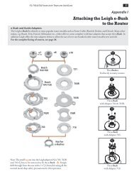
26<br />
Chapter 4 D4 User Guide<br />
OPERATION CONCEPTS AND BASIC JIG FUNCTIONS<br />
4-1<br />
The two clamp bars hold workpieces horizontally<br />
or vertically. The side stops align<br />
the boards in the same position each time.<br />
4-2<br />
The guidefinger assembly slides on to the<br />
support brackets above the workpiece.<br />
The finger assembly is adjusted in or out<br />
using calibrated scales on each end to suit<br />
different thicknesses of vertical boards.<br />
Note: The single rear indicator line on<br />
each support bracket is the only mark used<br />
in this guide. The front three lines are for<br />
the (optional) multiple mortise & tenon<br />
attachment.<br />
4-3<br />
The finger assembly is raised or lowered<br />
using the support brackets to suit different<br />
thicknesses of horizontal boards.
THE FOUR SCALE MODES<br />
The Finger Assembly attaches to the support<br />
brackets in four different modes to<br />
match the type of joint you are cutting.<br />
1 2<br />
1 2<br />
3 4<br />
1<br />
4<br />
≤<br />
1. TD TAILS<br />
1 2<br />
1<br />
2<br />
1<br />
4<br />
3<br />
4<br />
7<br />
16<br />
1<br />
2<br />
5<br />
16<br />
13<br />
16<br />
1 11<br />
2 16<br />
7<br />
16<br />
3<br />
8<br />
2. TD PINS<br />
This line is for the finger assembly<br />
scales. The line is illustrated in red<br />
for clarity, but is black on the jig.<br />
Always read scales from directly overhead<br />
to avoid parallax problems.<br />
Note: Inch scales are shown<br />
here. Millimetre scales have<br />
identical layout.<br />
The active scale is always<br />
on the right of each scale<br />
assembly.<br />
The inactive scale is always on<br />
the left of each scale assembly<br />
<strong>and</strong> is upside-down.<br />
Each scale has it’s own mode icon<br />
(a drawing of the joint part made<br />
in that mode).<br />
Scales are colour coded.<br />
Silver background for Through<br />
Dovetails.<br />
Green background for Half-<br />
Blind Dovetails.<br />
The specific settings for each<br />
scale are fully described in the<br />
appropriate chapters.<br />
These three lines are used only<br />
with the optional multiple<br />
mortise & tenon attachment.<br />
11<br />
16<br />
7<br />
3<br />
8<br />
16<br />
13<br />
16<br />
1 2<br />
≤<br />
5<br />
16<br />
1 2<br />
7<br />
16<br />
3<br />
4<br />
1 2<br />
1<br />
4<br />
3. HB TAILS<br />
1<br />
4<br />
4. HB PINS<br />
1 2<br />
3 4<br />
1 2<br />
1 2<br />
27
28<br />
Chapter 4 D4 User Guide<br />
CONCEPT OF JIG OPERATION – THROUGH DOVETAILS<br />
Start with the Finger Assembly in the D TD TAIL mode <strong>and</strong> follow these steps on your jig.<br />
Grasping the simple basic concept of operation will greatly assist you in underst<strong>and</strong>ing the<br />
instructions. Note that the active guide surface (against which the guidebush runs) is indicated in<br />
red in the illustrations.<br />
1.<br />
3.<br />
Start at<br />
THROUGH DOVETAIL<br />
TAILS (TD TAILS) mode.<br />
MODE ICONS<br />
Each illustration in this manual<br />
includes the correct<br />
mode icon for it’s<br />
current instruction.<br />
Icons are also used in the text.<br />
Now the Finger Assembly is in<br />
THROUGH DOVETAIL<br />
PINS (TD PINS) mode.<br />
OPERATION CONCEPTS AND BASIC JIG FUNCTIONS<br />
2.<br />
4.<br />
1 2<br />
1 2<br />
3 4<br />
1<br />
4<br />
≤<br />
ROTATE<br />
Rotate the finger assembly toward you 180°.<br />
1 2<br />
1<br />
2<br />
1<br />
4<br />
3<br />
4<br />
INCHES MILLIMETRES<br />
INCHES MILLIMETRES<br />
7<br />
16<br />
1<br />
2<br />
5<br />
16<br />
13<br />
16<br />
1 11<br />
2 16<br />
7<br />
16<br />
3<br />
8<br />
12,7 17,5<br />
11,1<br />
9,5<br />
FLIP<br />
Flip the Finger Assembly end-over-end 180°<br />
(to Half-Blind Dovetail Pins, Page 30)<br />
20,3<br />
26
ACTIVE GUIDE SURFACES<br />
ACTIVE GUIDE SURFACES<br />
29
30<br />
Chapter 4 D4 User Guide<br />
CONCEPT OF JIG OPERATION – HALF-BLIND DOVETAILS<br />
5.<br />
7.<br />
Now the Finger Assembly is in<br />
HALF-BLIND DOVETAIL<br />
PINS (HB PINS) mode.<br />
6.<br />
Now the Finger Assembly is in<br />
HALF-BLIND DOVETAIL<br />
TAILS (HB TAILS) mode.<br />
OPERATION CONCEPTS AND BASIC JIG FUNCTIONS<br />
≤<br />
1<br />
4<br />
1 2<br />
3 4<br />
1 2<br />
ROTATE<br />
Rotate the finger assembly toward you 180°.<br />
11<br />
16<br />
7<br />
3<br />
8<br />
16<br />
13<br />
16<br />
1 2<br />
INCHES MILLIMETRES<br />
INCHES MILLIMETRES<br />
5<br />
16<br />
1 2<br />
7<br />
16<br />
3<br />
4<br />
1 2<br />
1<br />
4<br />
1 2<br />
5<br />
20<br />
15<br />
10<br />
5<br />
10<br />
15<br />
20<br />
25–38<br />
25–38
7<br />
16<br />
1<br />
2<br />
3 4<br />
1 2<br />
1 4<br />
3 8<br />
13<br />
16<br />
1 1116<br />
2<br />
7<br />
16<br />
13<br />
16<br />
12 1116<br />
7<br />
16<br />
3<br />
8<br />
5<br />
16<br />
1 2<br />
ACTIVE GUIDE SURFACES<br />
ACTIVE GUIDE SURFACES<br />
5<br />
16<br />
7<br />
16<br />
1<br />
2<br />
3 4<br />
1 2<br />
1 2<br />
1 4<br />
31
32<br />
Chapter 4 D4 User Guide<br />
CONCEPT OF JIG OPERATION - SLIDING DOVETAIL JOINTS<br />
The HB TAILS mode is also used with the cross-cut bar to<br />
cut sliding dovetail joints.<br />
8.<br />
9.<br />
With the Finger Assembly in<br />
HALF-BLIND DOVETAIL<br />
TAILS (HB TAILS) mode,<br />
install the cross-cut bar.<br />
Sliding Dovetail slots<br />
are cut across the<br />
board face.<br />
Sliding Dovetail tails<br />
are cut across the board<br />
end edge.<br />
OPERATION CONCEPTS AND BASIC JIG FUNCTIONS<br />
11<br />
16<br />
7<br />
3<br />
8<br />
16<br />
13<br />
16<br />
1 2<br />
5<br />
16<br />
1 2<br />
7<br />
16<br />
3<br />
4<br />
1 2<br />
1<br />
4<br />
1 2<br />
Keep the finger assembly<br />
11<br />
16<br />
7<br />
3<br />
8<br />
16<br />
13<br />
16<br />
1 2<br />
INCHES MILLIMETRES<br />
5<br />
16<br />
1 2<br />
7<br />
16<br />
3<br />
4<br />
1 2<br />
1<br />
4<br />
1 2<br />
25–38<br />
20<br />
15<br />
10<br />
5<br />
INCHES MILLIMETRES<br />
25–38<br />
20<br />
15<br />
10<br />
5
5<br />
16<br />
in the same mode.<br />
7<br />
16<br />
1<br />
2<br />
3 4<br />
1 2<br />
1 4<br />
3 8<br />
13<br />
16<br />
1 1116<br />
2<br />
7<br />
16<br />
13<br />
16<br />
12 1116<br />
7<br />
16<br />
3<br />
8<br />
ACTIVE GUIDE SURFACE<br />
1 2<br />
3 8<br />
13<br />
16<br />
1 1116<br />
2<br />
7<br />
16<br />
13<br />
16<br />
12 1116<br />
7<br />
16<br />
3<br />
8<br />
ACTIVE GUIDE SURFACE<br />
5<br />
16<br />
7<br />
16<br />
1<br />
2<br />
3 4<br />
1 2<br />
1 2<br />
1 4<br />
5<br />
16<br />
5<br />
16<br />
7<br />
16<br />
1<br />
2<br />
7<br />
16<br />
1<br />
2<br />
3 4<br />
1 2<br />
1 2<br />
3 4<br />
1 4<br />
1 2<br />
1 2<br />
1 4<br />
33
34<br />
Chapter 4 D4 User Guide<br />
OPERATION CONCEPTS AND BASIC JIG FUNCTIONS