Anti-subsidence Measure Using King-post Cables against ...
Anti-subsidence Measure Using King-post Cables against ...
Anti-subsidence Measure Using King-post Cables against ...

You also want an ePaper? Increase the reach of your titles
YUMPU automatically turns print PDFs into web optimized ePapers that Google loves.
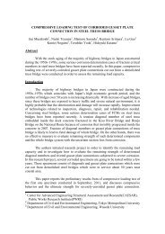
<strong>Anti</strong>-<strong>subsidence</strong> <strong>Measure</strong> <strong>Using</strong> <strong>King</strong>-<strong>post</strong> <strong>Cables</strong> <strong>against</strong> Subsidence in A PC Box Girder<br />
with Central Hinge<br />
Takeshi SUZUKI 1) , Shigeru MATSUMOTO 2) , Kousuke WAKATSUKI 3) ,<br />
Hideki MANABE 4)<br />
Abstract: Four dyvidag bridges with hinge on the Hanshin Expressway Network were<br />
found subsiding in the central hinge region. Displacement was most significant in the<br />
Kireuriwari Viaduct of the Osaka Matsubara Route which exhibited a <strong>subsidence</strong> of more<br />
than 30 cm from the initial level. <strong>Anti</strong>-<strong>subsidence</strong> measure was investigated as a part of the<br />
major repair work on this route in fiscal 2003. Through comparative studies between a<br />
composite truss, external cables installed inside the box girder and other proposals, a king<br />
<strong>post</strong> cable structure was chosen because of its advantages in terms of local and structural<br />
conditions of the bridge. This method was to install new struts to the underside of the main<br />
girder and lay external cables eccentrically. This report covers detailed design of the king<br />
<strong>post</strong> cable reinforcement technique.<br />
Keywords: continuous three-span PC rigid frame bridge with hinge, sag, king <strong>post</strong> cables,<br />
ASR, major repair work, soundness evaluation, maintenance plan<br />
1. Introduction<br />
The Kireuriwari Viaduct is a continuous<br />
three-span prestressed concrete (PC) rigid<br />
frame bridge with hinge completed in<br />
1979. Photo.1 shows the whole view of<br />
this 154 m long bridge. This type of<br />
structure was used in many bridges built<br />
in 1960s to 1980s, being considered<br />
favorable for long bridges with not so<br />
high piers. In such structures with hinge<br />
dead load bending moment in a<br />
Photo.1 View of the entire Kireuriwari Viaduct<br />
Fig.1 Hanshin expressway network<br />
Kireuriwari Viaduct<br />
1
completed structural system, horizontal seismic force is distributed to each pier, and there<br />
is no redundant force due to temperature change and drying shrinkage which usually<br />
occurs in ordinary continuous rigid frame bridge. However, many of them have been<br />
changed into continuous girders since hinge shoes required frequent maintenance and, in<br />
some of them, sagging or angle-bending was beyond design levels, causing problems with<br />
driving comfort and water drainage from bridge decks.<br />
The Kireuriwari Viaduct experienced the same problems, with a sag in the central hinge<br />
region found in 1985, after five years from the start of service in March 1980. Although<br />
overlay of 70 mm was applied in 1986 and again in 1993 in order to sustain serviceability,<br />
continued observation and examination suggested a possibility of further decline in its<br />
structural performance. The amount of sag already reached a considerable degree and was<br />
expected to further increase. Dynamic characteristics of the concrete indicated<br />
deterioration due to alkali-silica reaction (ASR). Since combined effects of creep in the<br />
concrete, ASR and other factors were suggested, it was decided to restore serviceability<br />
and prevent or even correct the sag using the king <strong>post</strong> cable reinforcement technique. This<br />
report covers the detailed design of this reinforcement.<br />
2. Current condition of the existing bridge<br />
2.1 General<br />
Table.1 and Fig. 2 show specifications and general views of the bridge which passes over<br />
the Uriwari intersection in Hirano-ku, Osaka. Since this site was a major intersection of<br />
two national roads (#309 and #479) with a daily traffic inflow of about 76,000 vehicles, the<br />
construction must be carried out under many restrictions including assured visibility for<br />
vehicles on the streets, compliance with clearance limits and limited space available for the<br />
work.<br />
Table.1 Specifications of the bridge<br />
Structure<br />
continuous 3-span prestressed concrete rigid frame twin main<br />
girder bridge with hinge<br />
Bridge length 154.0 m (span lengths: 44.450 + 65.000 + 44.450 m)<br />
Width 0.400 + 8.700 + 0.800 + 8.700 + 0.400 = 19.000 m<br />
Live load B live load (TL-20 at construction)<br />
Gradient incline: 1.167%; crossfall: 2.0% (upward gradient)<br />
Bearings 8 roller bearings, 162 tf (overall)<br />
Central hinged shoes 4 Gelenk shoes + 2 horizontal rubber bearings (overall)<br />
Concrete strength superstructure: 40 N/mm 2 ; substructure: 24 N/mm 2<br />
Prestressing steel<br />
internal cable: SBPR 930/1180 (dia. 26 mm; existing)<br />
external cable: SWPR7BL 19S15.2<br />
2
mm, respectively, in the central hinge region. None of the piers exhibited major <strong>subsidence</strong>.<br />
Cumulative amount of sag in the central hinge region measured in December 2002 was 236<br />
mm from the design longitudinal alignment. On the other hand, according to the records,<br />
this bridge was given an additional elevation of 85.4 mm at construction. Therefore, the<br />
actual cumulative amount of sag reached 321 mm. Although there was some influence of<br />
temperature variations between measurements, recent data revealed that the rate of sagging<br />
was increasing by about 2 mm to 9 mm each year.<br />
(2) Concrete properties<br />
Table.2 shows the results of investigation on concrete properties. Although the design<br />
characteristic strength was 40 N/mm 2 , actual compressive strength ranged from 28.0<br />
N/mm 2 to 45.5 N/mm 2 , suggesting lack of strength partially. Static modulus of elasticity<br />
was 60% to 80% of a design level of 3.5×10 4 N/mm 2 . Chemical tests and petrographic<br />
examinations revealed potential deleteriousness, indicating ASR as one of the possible<br />
causes of sagging.<br />
Year<br />
of test<br />
Sampling<br />
location<br />
Table.2 Investigation results: properties of the concrete<br />
Compressive<br />
strength<br />
(N/mm 2 )<br />
Static modulus<br />
of elasticity<br />
(×10 4 N/mm 2 )<br />
1987 Diaphragm 36.4--42.2 2.07--2.54<br />
Expansion (1×10 -6 )<br />
1988 Diaphragm 28.0--44.8 1.88--2.72 325--414<br />
1991 Diaphragm -- -- 153--295<br />
1992 Diaphragm 38.4--45.5 2.45--2.55 --<br />
2000 Web 29.7--30.6 2.13--2.34<br />
Mortar-bar: 327 (26W)<br />
Chemical: potentially<br />
deleterious<br />
JCI-DD2: 270 (13W)<br />
Canadian Std: 830 (28-day)<br />
(3) Cracking<br />
Cracking of the major part of the bridge was slight. However, alligator cracking occurred<br />
in the pier head regions, cross beams and other massive regions. Cracks in the slabs were<br />
found along the prestressing steel. In 1988, diagonal cracks were found in the central span<br />
at around one fourth the span length from each end. Cracking was significant in the outer<br />
webs which were exposed to environmental variations. Investigations were carried out to<br />
determine cracking behavior and influence of torsion, resulting in a reinforcement using<br />
the steel plate bonding technique in 1993.<br />
4
3.3 Details<br />
(1) Struts<br />
Struts and saddles were designed to have a simple and light-weight structure, using<br />
simplex steel pipes for the struts and duplex steel pipes filled with shrinkage-compensating<br />
mortar for the saddles 5) . Struts had ribs at their roots, with the pipes filled with<br />
shrinkage-compensating mortar for the height of the ribs in order to prevent stress from<br />
concentrating at the tips of the ribs.<br />
Members were designed using the three dimensional (3D) frame analysis, and local stress<br />
was examined using the 3D FEM analysis. Since the struts were crossing over the hinge,<br />
relative displacements between the two sides were measured at site and included in the<br />
design.<br />
Figure .6shows the 3D FEM analysis results under design load, with relative displacements<br />
taken into account. As shown in the case without filling (left) and the case with filling<br />
(right), minor principal stress at the tips of the ribs was improved by filling with mortar<br />
from −95.4 N/mm 2 to −65.1 N/mm 2 , or to 68%, indicating successful dispersion of stress.<br />
Although stress amplitude under live load was only 2.0% of that under full design load by<br />
the overall frame analysis, full penetration weld joints were adopted for the steel pipes for<br />
assured safety <strong>against</strong> fatigue in the struts.<br />
Safety <strong>against</strong> buckling in the struts was verified by a buckling ratio of 13.5 in the primary<br />
buckling mode.<br />
Compression<br />
Temsion<br />
-88.8N/mm 2<br />
Forced<br />
displacement<br />
-95.4N/mm 2<br />
-88.7N/mm 2<br />
-93.3N/mm 2<br />
-90.9N/mm 2<br />
Forced<br />
displacement<br />
Without shrinkage-compensating motar filling With shrinkage-compensating motar filling<br />
Fig. 6 3D FEM analysis on the struts<br />
-65.1N/mm 2<br />
-89.9N/mm 2<br />
-56.9N/mm 2<br />
(2) Horizontal rubber bearings in the central hinge region, and reinforcement of the<br />
existing cross beams<br />
7
5. Future examinations<br />
5.1 Design verification based on the property investigation results<br />
The current detailed design is a basis established based on the property values from<br />
previous investigations. Further investigations are under way at present for collecting<br />
property data, and measurements are planned to obtain residual prestress data which are<br />
not sufficient at this moment. Design verification will be carried out using these additional<br />
data which will represent the condition of the existing bridge more accurately.<br />
5.2 <strong>Measure</strong>ment plans for the existing bridge<br />
Previous data was insufficient to identify the major factors of the sag occurring in the<br />
central hinge region. Since the current reinforcement technique has not been proven by<br />
actual applications, it is necessary to confirm if the existing bridge behaves as calculated in<br />
the design. Following measurements are planned for both design verification and future<br />
maintenance.<br />
(1) Displacement in major members and stress in the main girder cross-section will be<br />
measured during prestressing so that tension in the king <strong>post</strong> cables will be controlled<br />
at real time.<br />
(2) Static loading tests will be performed before and after prestressing in order to verify<br />
effect of the current reinforcement and behavior caused by live load.<br />
(3) Follow-up investigations will be carried out to confirm preventive effect <strong>against</strong><br />
sagging and establish proper maintenance plans, so that soundness after the<br />
reinforcement will be evaluated and basic data required for preparing maintenance<br />
manuals will be collected.<br />
Reference<br />
1) Assistant Manager, Survey and Design Division, Osaka Business and Maintenance<br />
Department, Hanshin Expressway Public Corporation<br />
2) Assistant Manager, Survey and Design Division, Kobe Business and Maintenance<br />
Department, Hanshin Expressway Public Corporation<br />
3) Survey and Design Division, Osaka Business and Maintenance Department, Hanshin<br />
Expressway Public Corporation<br />
4) Manager ,Technical development Department, Osaka Branch, Fuji P.S. Corporation,<br />
Pr.Eng.<br />
5) Shinozaki, et al.: Study on fatigue durability of deviation zone members in an externally<br />
prestressed truss bridge having large eccentricities, Proc. of JCI, Vol. 24, No. 2, pp.<br />
595--600, 2000<br />
6) Expressway Technology Center: Design manual for PC bridges using external cables, pp.<br />
51--52, August 1996<br />
7) Japan Prestressed Concrete Engineering Association: External cable structures, precast<br />
concrete design and construction standards (proposal), pp. 72--73, March 1996<br />
8) Matsumoto, et al.: Evaluation of natural vibration characteristics of the Torisaki River<br />
Park Bridge, Proc. of JSCE, pp. 1163--1164, 2002<br />
9) Sakai: Repair on the Misasagi Bridge, Bridge and Foundation Engineering, August 1983<br />
10) Hashiba, et al.: Study on time dependent displacement in a PC rigid frame bridge<br />
having hinge, Proc. of JSCE, No. 478/V-21, November 1993<br />
11)Sakamoto, et al.: Soundness evaluation and reinforcement plan for the Jintsugawa<br />
Bridge, Bridge and Foundation Engineering, pp. 27--31, April 2003<br />
10