
Create successful ePaper yourself
Turn your PDF publications into a flip-book with our unique Google optimized e-Paper software.
<strong>Leigh</strong> <strong>Dovetail</strong> <strong>Jig</strong><br />
Joining Tradition with Today<br />
USER GUIDE<br />
-D1600-Ch-Gloss.indd 1 4/4/05 12:00:28 PM
ii<br />
Your New <strong>Leigh</strong> <strong>Dovetail</strong> <strong>Jig</strong><br />
Congratulations! You now own a most useful and<br />
versatile dovetailing tool. The <strong>Leigh</strong> D1600 <strong>Dovetail</strong><br />
<strong>Jig</strong> will help you cut an infinite variety of joints, and<br />
all of its major functions are described in detail in<br />
this manual. A very helpful DVD is also included,<br />
but the manual is essential reading.<br />
We recommend that you first assemble and mount<br />
the jig, carefully following the instructions in the<br />
first section of the manual. Then read the rest of the<br />
manual, following along with the basic functions<br />
and principles of operation, before you try to do<br />
any actual joinery routing. By all means, cut a few<br />
practice joints in scrap boards before you use the jig<br />
to rout a precious hardwood work piece!<br />
Important! Inches and Millimetres<br />
<strong>Leigh</strong> makes the D1600 jig in two models; inch<br />
and metric. The two models are identical except for<br />
scales. Text and illustrations in this <strong>Leigh</strong> Englishlanguage<br />
user guide indicate dimensions in both<br />
inches and millimetres, with “inches” first, followed<br />
by “millimetres” in square brackets.<br />
Example: 3⁄4"x 5 1⁄2"x8" [20x140x200mm]<br />
1<br />
2<br />
G L O S S A R Y O F S Y M B O L S<br />
If you have any questions that are not<br />
answered in the manual, please call the <strong>Leigh</strong><br />
customer support line*.<br />
But remember: “If at first you don’t succeed,<br />
read the instructions!”<br />
*See Appendix IV – Customer Support<br />
Do not be concerned if the inch/millimetre<br />
equivalents are not exact. Just use the dimensions<br />
which apply to your jig.<br />
Where finger assembly scales overlay an illustration,<br />
the “inches” scale ➀ will be at the top,<br />
the “millimetres” scale ➁ will be at the bottom.<br />
Only the front “active” half of the scales<br />
are illustrated. For clarity, setting positions<br />
are indicated with a red line in the manual<br />
only. On the jig, the lines are black.<br />
-D1600-Ch-Gloss.indd 2 4/4/05 12:00:29 PM
C O N T E N T S<br />
Glossary of Symbols ......................................................................iv<br />
Chapter 1 – <strong>Jig</strong> Assembly, Mounting, and Using The Clamps ............ 1<br />
Chapter 2 – Adjusting the Finger Assembly ................................... 11<br />
Chapter 3 – How Routers with Guidebushes Work ........................ 15<br />
Chapter 4 – Operation Concepts and Basic <strong>Jig</strong> Functions ................ 17<br />
Chapter 5 – Using Your <strong>Jig</strong> Safely ................................................. 27<br />
Chapter 6 – Wood Preparation .................................................... 31<br />
Chapter 7 – Router Preparation .................................................... 33<br />
Chapter 8 – Through <strong>Dovetail</strong> Procedures ..................................... 37<br />
Chapter 9 – Half-Blind <strong>Dovetail</strong> Procedures .................................. 51<br />
Chapter 10 – Rabbeted Half-Blind <strong>Dovetail</strong>s ................................. 65<br />
Chapter 11 – Asymmetric <strong>Dovetail</strong>s .............................................. 69<br />
Chapter 12 – Sliding <strong>Dovetail</strong> Procedures .................................... 75<br />
Chapter 13 – Quick Reference – Through <strong>Dovetail</strong>s ....................... 85<br />
Chapter 14 – Quick Reference – Half-Blind <strong>Dovetail</strong>s ..................... 89<br />
Chapter 15 – Hints and Tips .......................................................... 93<br />
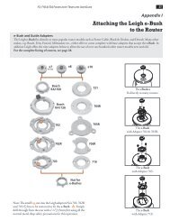
Appendix I – Guidebush Selection .............................................. 101<br />
Appendix II – Cutter Selection ..................................................... 105<br />
Appendix III – <strong>Jig</strong> Parts List ......................................................... 113<br />
Appendix IV – Customer Support ................................................ 117<br />
-D1600-Ch-Gloss.indd 3 4/4/05 12:00:29 PM<br />
ii iii
iv<br />
2<br />
1<br />
Sometimes a joint mode icon will be used to identify a board➂.<br />
3<br />
G L O S S A R Y O F S Y M B O L S<br />
Glossary of Symbols<br />
To help you understand the instructions and<br />
illustrations in this manual, we have used a<br />
number of international symbols, plus a few<br />
special ones of our own. They are all explained<br />
below. You needn’t worry about memorizing<br />
these symbols now, because they are repeated<br />
quite frequently in the manual, and you will<br />
soon get used to them.<br />
The <strong>Leigh</strong> jig’s guidefinger assembly can be<br />
in any one of four joint modes, depending on<br />
what type of joint and which part of the joint<br />
you are cutting. Each finger assembly scale has<br />
it’s own mode icon➀, identifying that joint<br />
part. You will also find the joint mode icon in<br />
the top left corner of most illustrations➁, indicating<br />
which finger assembly mode to use.<br />
These are the four joint mode icons:<br />
TD Tails<br />
(tails for through dovetail joints)<br />
TD Pins<br />
(pins for through dovetail joints)<br />
HB Tails<br />
(tails for half-blind dovetail joints)<br />
HB Pins<br />
(pins for half-blind dovetail joints)<br />
-D1600-Ch-Gloss.indd 4 4/4/05 12:00:30 PM
Which Way Round Should the Board Go?<br />
As virtually all dovetail joinery is used to make<br />
boxes, drawers and chests etc., we devised these<br />
simple (and hopefully intuitive) icons to indicate<br />
which side of a board faces inwards or<br />
outwards on the finished “box”, and which side<br />
of the board faces outward (toward you, the<br />
operator), when it is clamped in the jig.<br />
The following symbols indicate:<br />
e This edge against sidestop<br />
f This edge against sidestop<br />
Sawcut allowance<br />
<br />
This icon o indicates the "outside"<br />
of a board. All through dovetail pin<br />
boards are mounted in the jig with<br />
this "outside" face away from the<br />
jig (toward you, the operator).<br />
This icon i indicates the "inside"<br />
of a board. All half-blind pin and<br />
half-blind tail boards, and through<br />
dovetail tail boards, are mounted<br />
in the jig with the "inside" face<br />
away from the jig toward you,<br />
the operator.<br />
This icon j indicates boards that<br />
are mounted both ways e.g. sliding<br />
dovetails.<br />
Dotted line icons indicate the<br />
"other" side of the board in the<br />
illustrations.<br />
Caution: use special care for this<br />
operation<br />
➀➁➂ Numbered References in text<br />
Centreline of board or layout<br />
Equals<br />
Does not equal<br />
Approximately<br />
-D1600-Ch-Gloss.indd 5 4/4/05 12:00:36 PM<br />
v
vi<br />
G L O S S A R Y O F S Y M B O L S<br />
-D1600-Ch-Gloss.indd 6 4/4/05 12:00:38 PM