
You also want an ePaper? Increase the reach of your titles
YUMPU automatically turns print PDFs into web optimized ePapers that Google loves.
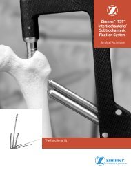
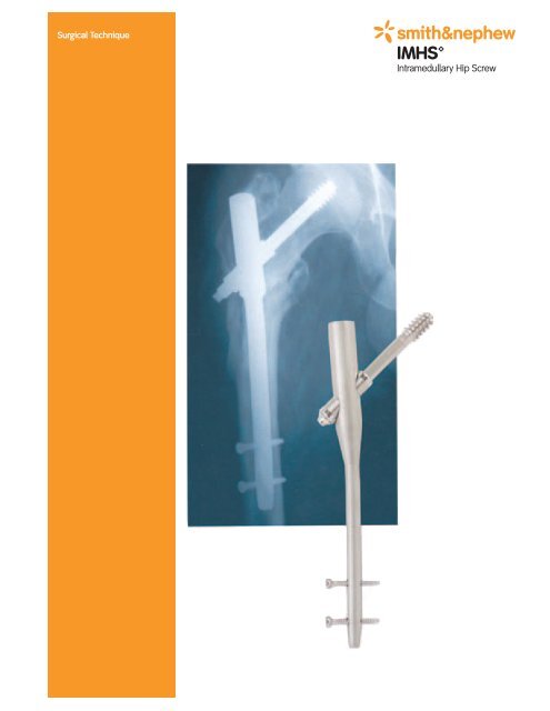
Surgical <strong>Technique</strong>
<strong>IMHS</strong> Intramedullary Hip Screw<br />
Surgical <strong>Technique</strong><br />
by<br />
Mr. John S. Albert, B.Sc., M.B., F.R.C.S.<br />
The Orthopaedic Department<br />
Norfolk & Norwich Hospital<br />
Brunswick Road<br />
Norwich, England<br />
Contents<br />
Design Features ................................................................4<br />
The <strong>IMHS</strong> Nail ..................................................................5<br />
Indications ........................................................................6<br />
Specifications ....................................................................6<br />
Surgical <strong>Technique</strong> ............................................................8<br />
<strong>IMHS</strong> Removal ................................................................26<br />
Catalog Information ........................................................27<br />
Nota Bene<br />
The technique description herein is made available to the healthcare professional to<br />
illustrate the author's suggested treatment for the uncomplicated procedure. In the final<br />
analysis, the preferred treatment is that which addresses the needs of the specific patient.
Design Features<br />
Keyed Centering<br />
Sleeve<br />
Easy sliding<br />
Prevents rotation<br />
AMBI/CLASSIC<br />
Compression<br />
Screw<br />
Lengths – 19.0 mm<br />
and 28.5 mm<br />
Standard <strong>IMHS</strong> Nail<br />
Angles – 130° and 135°<br />
Proximal diameter – 17.5 mm<br />
Length – 21 cm<br />
Universal<br />
Distal Diameter Wall Thickness<br />
10 mm 2.4 mm<br />
12 mm 2.3 mm<br />
14 mm 1.7 mm<br />
16 mm 1.2 mm<br />
4.5 mm Self-Tapping<br />
Cortical Bone Screws<br />
25 lengths – 16 mm-64 mm<br />
4<br />
Set Screw<br />
Medialized<br />
moment arm<br />
4° mediolateral bend,<br />
for improved anatomic fit<br />
Long Intramedullary<br />
Hip Screw<br />
AMBI/CLASSIC Lag<br />
Screw<br />
Lengths – 70 mm-140 mm<br />
Thread diameter – 12.7 mm<br />
Root diameter – 9.0 mm<br />
Nonself-tapping, for<br />
cancellous bone<br />
Scratch Resistant Surface (SRS)<br />
Long <strong>IMHS</strong> Nail<br />
Angles – 130° and 135°<br />
Anteversion – 10°<br />
A-P curvature matches that of the<br />
femur (2.3 meter radius)<br />
Proximal diameter – 17.5 mm<br />
Distal diameter – 10 mm and 12 mm<br />
Lengths – 34 cm, 38 cm, and 42 cm<br />
Left/Right nails<br />
Wall thickness – 2.4 mm
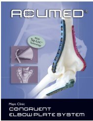
The <strong>IMHS</strong> Nail<br />
<strong>IMHS</strong> features a cannulated intramedullary nail<br />
with a 4° mediolateral bend to allow for insertion<br />
through the greater trochanter. The nail is used<br />
with a standard Richards AMBI/CLASSIC Lag<br />
Screw (1/2" thread diameter), compression screw,<br />
and 4.5 mm locking screws. A sleeve, which is<br />
held by a set screw, passes through the<br />
intramedullary nail and over the lag screw. The<br />
sleeve helps prevent rotation, while allowing the<br />
lag screw to slide. The Standard <strong>IMHS</strong> nail is<br />
available in two angles - 130° and 135° - and in<br />
four diameters - 10 mm, 12 mm, 14 mm, and 16<br />
mm, to allow a proper fit within the femoral canal.<br />
The Standard <strong>IMHS</strong> nails are all 21 cm in length.<br />
<strong>IMHS</strong> is locked using one or two 4.5 mm locking<br />
screws.<br />
The Long <strong>IMHS</strong> has a distal diameter of 10 mm and<br />
12 mm is available in lengths of 34 cm, 38 cm, and<br />
42 cm. 130° and 135° angles are available as with<br />
the Standard <strong>IMHS</strong>. The Long <strong>IMHS</strong> nail has a 2.3<br />
meter radius to conform with the natural bow of<br />
the femoral shaft and 10° of anteversion to match<br />
the angle of the femoral head in relation to the<br />
shaft of the femur. Distal locking is carried out<br />
using 4.5 mm locking screws.<br />
Both types of <strong>IMHS</strong> nails have a proximal diameter<br />
of 17.5 mm.<br />
Standard <strong>IMHS</strong> Nail<br />
Intertrochanteric<br />
fractures<br />
Subtrochanteric<br />
fractures<br />
5
Indications<br />
Intramedullary Hip Screws (<strong>IMHS</strong>), provide an intramedullary approach to<br />
fractures of the proximal femur and are particularly suited to unstable<br />
peritrochanteric fractures, reverse obliquity fractures, and subtrochanteric<br />
fractures. The Long <strong>IMHS</strong> nail is designed for subtrochanteric fractures,<br />
comminuted neck and shaft fractures, femur reconstruction following tumor<br />
resection, prophylactic nailing of impending pathologic fractures, and leg<br />
length discrepancies secondary to femoral fracture.<br />
Specifications<br />
Standard Lag Screw (Proximal)<br />
Major<br />
Diameter<br />
Minor<br />
Diameter<br />
Thread<br />
Length<br />
6<br />
12.7mm<br />
9.0mm (tapered<br />
6.6 - 9.1)<br />
21.0mm<br />
Lengths 70-140 in 5mm<br />
increments<br />
Self Tap No<br />
Centering Sleeve (Keyed)<br />
O.D. 12.7mm<br />
I.D. 9mm<br />
Length 38.1mm<br />
Compressing Screw<br />
Hex<br />
Diameter<br />
3.5mm<br />
Length 19 & 28.5mm<br />
* For additional strength & larger<br />
screw use 5.0mm RT screw in distal<br />
hole only for long and short nails –<br />
Cannot be used in distal slot of Long<br />
12mm distal diameter nails.<br />
NOTE: When using alternative<br />
screws be sure to use hexdriver<br />
and drill bit specific to the screw.<br />
Do not use a Super Lag<br />
Screw with <strong>IMHS</strong><br />
(will not pass through nail)<br />
Set Screw<br />
Hex<br />
Diameter<br />
4.5mm Screw (Distal)<br />
Head<br />
Diameter<br />
Major Thread<br />
Diameter<br />
Minor<br />
Diameter<br />
8.0mm<br />
4.5mm<br />
3.2mm<br />
Lengths 16-64 in 2mm<br />
increments<br />
Package 1<br />
Self Tap Yes<br />
Head<br />
Diameter<br />
4.0mm<br />
*5.0mm RT Screw<br />
Major Thread<br />
Diameter<br />
Minor<br />
Diameter<br />
Hex<br />
Diameter<br />
8.0mm<br />
5.0mm<br />
4.0mm<br />
4.0mm
Standard <strong>IMHS</strong> Nail<br />
Long <strong>IMHS</strong> Nail<br />
10mm 12mm 14mm 16mm<br />
Angles [ o ] 130/135 130/135 130/135 130/135<br />
Anterior Bow None None None None<br />
Anteversion [ o ] None None None None<br />
Distal Hole<br />
Size [mm]<br />
Distal Slot<br />
Width [mm]<br />
Driving End<br />
(O.D.) [mm]<br />
Guide Bolt Thread 9/16 - 18<br />
UNF<br />
5.5 5.5 5.5 5.5<br />
None None None None<br />
17.5 17.5 17.5 17.5<br />
9/16 - 18<br />
UNF<br />
9/16 - 18<br />
UNF<br />
Lengths [cm] 21 21 21 21<br />
Shaft Diameter<br />
(O.D.) [mm]<br />
10 12 14 16<br />
Smallest THRU<br />
Diameter [mm]<br />
3.9 5 6.6 8.6<br />
Wall Thickness [mm] 2.5 2.3 1.7 1.3<br />
9/16 - 18<br />
UNF<br />
10mm 12mm<br />
Angles [ o ] 130/135 130/135<br />
Anterior Bow 2.3 meter radius 2.3 meter radius<br />
Anteversion [ o ] 10 10<br />
Distal Hole Size [mm] 5.3 5.3<br />
Distal Slot Width [mm] — 4.7<br />
Driving End (O.D.) [mm] 17.5 17.5<br />
Guide Bolt Thread 9/16 - 18 UNF 9/16 - 18 UNF<br />
Lengths [cm] 34 38 42 34 38 42<br />
Shaft Diameter (O.D.) [mm] 10 12<br />
Smallest THRU Diameter [mm] 4.1 6<br />
Wall Thickness [mm] 2.5 1.2<br />
42 mm<br />
17 mm<br />
Note: Ball tip guide rods will not<br />
pass thru 10mm short and 10mm<br />
long nails. Will work for all other<br />
diameter nails.<br />
9.5 mm distal slot<br />
allows for<br />
dynamization<br />
(Long 12mm Distal<br />
Diameter Only)<br />
17 mm<br />
17.5 mm<br />
48.5 mm<br />
4 o<br />
Mediolateral<br />
bend<br />
*21 cm<br />
*18cm length made<br />
in SPS.<br />
9.5 mm<br />
42 mm<br />
7
Surgical <strong>Technique</strong><br />
Preoperative Planning<br />
The operation is performed on a standard fracture<br />
table and requires the use of an image intensifier<br />
which will produce images in two planes. Apart<br />
from standard surgical instruments, a power drill<br />
with reaming capability is required.<br />
Before embarking upon the procedure, obtain<br />
anteroposterior and lateral views of the proximal<br />
one half of the femur, either fluoroscopically at the<br />
time of the operation or on a preoperative<br />
roentgenogram. Severe deformities of the femoral<br />
canal or excessive anterior bowing may preclude<br />
the use of an intramedullary device.<br />
Radiographic templates are available. These allow<br />
preoperative estimation of the nail's diameter and<br />
angle and the lag screw's length.<br />
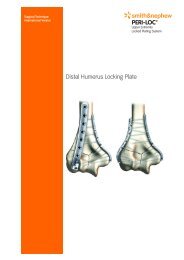
Patient Positioning and<br />
Preparation<br />
In general, the position used for the Intramedullary<br />
Hip Screw is similar to that employed for all supine<br />
intramedullary nailings of the femur.<br />
Place the patient supine on a standard fracture<br />
table. Both feet may rest in a padded foot holder.<br />
Use a padded perineal post.<br />
The pelvis must lie in the horizontal position.<br />
Adduct the affected femur to allow access to the<br />
trochanteric region. With the patient in a supine<br />
position, abduct the unaffected limb while<br />
adducting the trunk and affected extremity. Tilt the<br />
trunk away from the fracture and strap the arm on<br />
the same side across the chest of the patient. This<br />
is particularly important in obese patients.<br />
8
Place the uninjured leg either adjacent to the<br />
injured side (in the "heel-to-toe" position with the<br />
uninjured side lower), or flexed and abducted to<br />
allow unimpeded access of the image intensifier<br />
between the legs (Figure 1).<br />
Before the start of the operative procedure, it is<br />
important to achieve reduction of the fracture.<br />
Peritrochanteric fractures are usually reduced with<br />
internal rotation of the femur and traction. Most<br />
subtrochanteric fractures are commonly reduced<br />
by a small degree of external rotation. Avoid<br />
excessive traction of the affected limb. It is<br />
especially important to ensure that the head<br />
fragment of the femur is reduced to the shaft<br />
fragment in the lateral position. In the majority of<br />
cases, a satisfactory reduction should be achieved<br />
before beginning the operative procedure. If closed<br />
reduction is impossible, perform a more extensive<br />
operative incision and an open reduction of the<br />
fracture.<br />
A successful outcome is unlikely if the implant is<br />
inserted into an unreduced fracture. Comminuted<br />
peritrochanteric fractures, with loss of the medial<br />
cortical buttress including the lesser trochanter,<br />
are more likely to result in failure of fixation. In<br />
such cases, an intramedullary device may reduce<br />
the risk of failure.<br />
NOTE: It is very important to obtain satisfactory<br />
images of the fracture and the upper femur, in<br />
both the A-P and lateral planes, before<br />
beginning the operation.<br />
Figure 1<br />
9
Prepare the operative field in the usual manner.<br />
The sterile field extends from just above the iliac<br />
crest to the knee and from beyond the midline<br />
anteriorly to the midline posteriorly. Draping is<br />
comparable to that of conventional internal<br />
fixation of hip fractures. A vertical “sail-type”<br />
plastic drape is commonly used because it allows<br />
the operative field to be separated from the image<br />
intensifier and any unscrubbed personnel.<br />
Surgical Approach<br />
Make a lateral approach, similar to all<br />
intramedullary procedures of the femur. Extend<br />
the skin incision from the tip of the trochanter<br />
proximally for 3-8 cm depending on the size or<br />
obesity of the patient (Figure 2). Split the<br />
aponeurosis of the gluteus maximus in line with<br />
its fibers, from the tip of the trochanter proximally<br />
for 5 cm. This brings into view a small fat pad<br />
which lies between the tip of the trochanter and<br />
the piriformis fossa. Then, split the gluteus<br />
medius in the line of its fibers.<br />
The eventual size of the surgical incision depends<br />
on both the obesity of the patient and whether<br />
the fracture has been adequately reduced. In the<br />
majority of cases, a satisfactory reduction is<br />
achieved before the operative procedure is<br />
started. If an open reduction is necessary, extend<br />
the surgical approach distally to allow an anterior<br />
approach to the hip capsule and fracture. Check<br />
the adequacy of the open reduction<br />
radiographically. It is critical that the head<br />
fragment is reduced on the shaft fragment in the<br />
lateral plane.<br />
10<br />
Figure 2
Femoral Preparation<br />
Unlike the standard entry point for femoral nails<br />
in the piriformis fossa, insert the <strong>IMHS</strong> nail<br />
through the tip of the greater trochanter. The 4°<br />
bend allows this without encroachment of the<br />
femoral neck, which may be fractured.<br />
NOTE: The red numbered delta symbols<br />
match the numbering system in the<br />
sterilization trays. All instruments are<br />
numbered in order of use, providing<br />
guidance to the O.R. staff in anticipating the<br />
surgeon’s instrumentation needs.<br />
Following adequate exposure of the tip of the<br />
trochanter with the Curved Awl , (Figure 3)<br />
position the Tissue Protector on the tip of<br />
the trochanter and insert a 3.2 mm Tip<br />
Threaded Guide Pin through the Tissue<br />
Protector’s guide pin centering sleeve (Figure 4).<br />
Advance the pin down the femoral canal well<br />
beyond the subtrochanteric region. Check the<br />
position of the pin radiographically in the A-P<br />
and lateral planes.<br />
Curved<br />
Awl<br />
Tissue<br />
Protector<br />
3.2 mm Tip Threaded<br />
Guide Pin<br />
Figure 3<br />
Figure 4<br />
11
Remove the guide pin centering sleeve from the<br />
Tissue Protector. Use the Proximal Reamer to<br />
open the proximal portion of the femur to 18 mm<br />
to accommodate the proximal portion of the nail<br />
(17.5 mm). The minimum length of femur that<br />
requires reaming is 7 cm. The proximal reamer’s<br />
positive stop has 3 settings. The “7” setting will<br />
ream to 7 cm, the “7.5” setting will ream to 7.5 cm,<br />
and the “8” setting will ream to 8.0 cm. Once the<br />
positive stop is set, guide the Proximal Reamer<br />
over the Guide Pin and through the Tissue<br />
Protector and ream until the positive stop meets<br />
the outer portion of the Tissue Protector (Figure 5).<br />
In elderly patients with peritrochanteric fractures,<br />
the bone of the proximal femur, and in particular<br />
the fractured greater trochanter, is often very soft.<br />
The tip of the greater trochanter may be opened<br />
with the Curved Awl and checked radiographically<br />
in the A-P and lateral planes. Then, ream the<br />
proximal femur to 18 mm using the Proximal<br />
Reamer without the use of a Ball Tipped Guide<br />
Pin. Reaming over a 3.2 mm Tip Threaded Guide<br />
Pin is optional. If the trochanteric region is<br />
very osteoporotic, proximal reaming may<br />
be unnecessary.<br />
The <strong>IMHS</strong> nail is available in four diameters and<br />
two angles — 130° and 135°. Using the templates<br />
on the preoperative radiograph, estimate the<br />
appropriate diameter of the nail and the ideal<br />
angle and length for the lag screw. The final<br />
decision on the lag screw angle is a matter of<br />
experience. The majority of cases will require an<br />
angle of 130°.<br />
Use one of the four Trials to verify the<br />
appropriate nail diameter. Place the appropriate<br />
diameter trial on either the Trial Handle or the<br />
Drill Guide . Insert the Trial through the<br />
prepared proximal femur to ensure that the<br />
implant will fit in the medullary canal. It is<br />
preferable to use a smaller diameter implant than<br />
one which is tight within the canal.<br />
12<br />
Proximal<br />
Reamer<br />
Trial Trial<br />
Handle<br />
Figure 5<br />
Drill<br />
Guide<br />
Positive Stop
Using the Drill Guide and the appropriate Angle<br />
Guide Attachment , insert a guide pin into the<br />
femoral head to verify the angle. Refer to the<br />
Proximal Targeting section for the proper<br />
technique. Always remove the guide pin before<br />
removing the trial.<br />
NOTE: There is no trial for the Long <strong>IMHS</strong><br />
implant. If the canal is narrow and will not<br />
accommodate a 10 mm nail, then standard<br />
intramedullary reaming should be carried out<br />
over a Ball Tipped Guide Rod. The femur<br />
should be reamed to 1 mm larger than the<br />
nail’s diameter. Special attention should be<br />
paid to the anterior bow to ensure that a nail<br />
of the correct length and orientation, left or<br />
right, is used.<br />
Drill Guide And Nail Assembly<br />
The assembly of the Drill Guide with the chosen<br />
nail and the corresponding Angle Guide<br />
Attachment is critical. If the Angle Guide<br />
Attachment and nail are incorrectly matched, it<br />
will be impossible to insert the lag screw. For this<br />
reason, it is recommended that you assemble the<br />
Angle Guide Attachment to the Drill Guide prior to<br />
insertion of the Intramedullary Hip Screw.<br />
First, assemble the Drill Guide to the Drill Guide<br />
Handle (Figure 6). Secure the selected Angle<br />
Guide Attachment to the Drill Guide with the<br />
Angle Guide Attachment Bolt and tighten using<br />
the 11/16" Universal Socket Wrench<br />
(Figure 7).<br />
Angle Guide<br />
Attachment<br />
11/16”<br />
Universal<br />
Socket Wrench<br />
Figure 6<br />
Figure 7<br />
13
Next, attach the appropriate nail to the drill guide<br />
assembly with the Drill Guide Bolt (Figure 8).<br />
Tighten the bolt using the 11/16" Universal Socket<br />
Wrench . Then, attach the Driver to the<br />
Drill Guide and tighten using the 9/16" Open End<br />
Wrench (Figure 9).<br />
Confirm correct assembly by passing the Sleeve<br />
Reamer through the Silver Drill Sleeve and<br />
the proximal hole of the <strong>IMHS</strong> nail (Figure 10).<br />
NOTE: When using the Long <strong>IMHS</strong> nail, make<br />
sure the bow is anterior.<br />
Nail Insertion<br />
In most cases, the <strong>IMHS</strong> nail can be inserted<br />
without the use of a guide rod. Insert the tip of<br />
the nail into the prepared proximal femur and<br />
push it down the shaft. Carry this out under<br />
fluoroscopic control. Under no circumstances<br />
should the nail and driver assembly be<br />
hammered down the femur. If the nail will not<br />
pass easily down the canal with simple, gentle<br />
twisting movements of the driver assembly, it<br />
should be removed and the canal reamed by 1 or<br />
2 mm before reinsertion.<br />
Remove the Driver since this part of the assembly<br />
is no longer needed. If the Driver has tightened<br />
during nail insertion, the 9/16" Open End Wrench<br />
can be used to loosen it. The remainder of the<br />
insertion apparatus does not obscure the femoral<br />
head on the lateral radiograph.<br />
14<br />
9/16”<br />
Open End<br />
Wrench<br />
Driver Sleeve<br />
Reamer<br />
Combination<br />
Reamer<br />
(Alternative)<br />
Figure 8<br />
Figure 9<br />
Figure 10<br />
Silver Drill<br />
Sleeve
Proximal Targeting<br />
Correct positioning of the nail is critical to ensure<br />
that the lag screw will be placed in the center of<br />
the femoral head in both A-P and lateral planes.<br />
Two Silver Drill Sleeves are available for use with<br />
the Angle Guide Attachment, lengths 14 cm and<br />
16 cm. When the nail is in the correct position,<br />
thread the appropriate Drill Sleeve into the Angle<br />
Guide Attachment.<br />
Make an incision in the skin to allow the selected<br />
size Silver Drill Sleeve to be screwed in until it is<br />
flush with the Angle Guide Attachment (Figure 11).<br />
Choose the sleeve that comes closest to the lateral<br />
cortex without impeding its ability to be completely<br />
screwed into the Angle Guide Attachment. Insert<br />
the Guide Pin Sleeve until it rests on the lateral<br />
cortex of the femur (Figure 12). It is important that<br />
the sleeve fit flush against the femur to reduce the<br />
likelihood of the guide pin “walking.” Using A-P<br />
fluoroscopy, estimate the approximate position of<br />
the lag screw.<br />
Insert a 3.2 mm Tip Threaded Guide Pin<br />
through the Guide Pin Sleeve and into the femoral<br />
neck and head. The position of the guide pin, and<br />
thus the ultimate position of the lag screw, can<br />
now be determined both on A-P and lateral<br />
radiographic screening. If any fine adjustments in<br />
the nail depth need to be made, withdraw the<br />
guide pin and slightly insert or withdraw the <strong>IMHS</strong><br />
nail until the correct final position is achieved.<br />
The perfect position of the guide pin is in the exact<br />
center of the femoral neck and head on both the<br />
A-P and lateral views. The pin should certainly lie<br />
within the central third of the femoral neck and<br />
head on both radiographic views. When the correct<br />
position of the guide pin is achieved in both<br />
planes, advance it to within 5 mm of the articular<br />
surface of the femoral head (Figure 13).<br />
Guide Pin<br />
Sleeve<br />
3.2 mm Tip Threaded<br />
Guide Pin<br />
Figure 11<br />
Figure 12<br />
Figure 13<br />
15
Selecting The Lag Screw<br />
After insertion of the guide pin, remove the<br />
Guide Pin Sleeve from the Silver Drill Sleeve so<br />
that the lag screw length measurement can be<br />
correctly determined. Position the Lag Screw<br />
Length Gauge so that it rests against the<br />
guide pin and is flush with the Silver Drill<br />
Sleeve. Read the length of the lag screw directly<br />
from the guide pin (Figure 14).<br />
Reaming For The Lag Screw<br />
Use the Lag Screw Shaft Reamer to prepare<br />
the femoral neck for the lag screw. The correct<br />
depth for reaming is 5 mm less than the length<br />
of the guide pin, as previously measured. This<br />
will reduce the likelihood of the guide pin being<br />
removed with the Reamer. Set the Lag Screw<br />
Shaft Reamer to the correct length and advance<br />
it through the Silver Drill Sleeve and into the<br />
femoral head until the positive stop makes<br />
contact with the Silver Drill Sleeve (Figure 15). (If<br />
the guide pin is removed with the reamer,<br />
reinsert the Guide Pin Sleeve and reintroduce<br />
the guide pin without moving the external jig.)<br />
Check the position radiographically and remove<br />
the Lag Screw Shaft Reamer. Insert the Sleeve<br />
Reamer to ream the lateral cortex and metaphysis<br />
until the positive stop makes contact<br />
with the Silver Drill Sleeve (Figure 16). Remove<br />
the Sleeve Reamer.<br />
NOTE: The <strong>IMHS</strong> Lag Screw/Barrel Reamer<br />
can be used to ream for the Lag Screw and<br />
Centering Sleeve all in one step.<br />
16<br />
Lag Screw<br />
Length<br />
Gauge<br />
Lag Screw<br />
Shaft<br />
Reamer<br />
Sleeve<br />
Reamer<br />
Figure 14<br />
Figure 15<br />
Figure 16<br />
Combination<br />
Reamer<br />
(Alternative)<br />
Positive<br />
Stop
Tapping For The Lag Screw<br />
In an osteoporotic femur, tapping is<br />
unnecessary. In younger individuals, tapping<br />
the femoral neck to prepare for the lag screw is<br />
preferred. Otherwise, there may be a tendency<br />
for the femoral neck and head fragment to<br />
rotate during the insertion of the lag screw. Set<br />
the Lag Screw Tap for the same length as<br />
the Lag Screw Shaft Reamer (5 mm less than<br />
the guide pin measurement) and insert it<br />
through the Silver Drill Sleeve (Figure 17).<br />
Selection Of The Lag Screw<br />
Use a standard AMBI/CLASSIC Lag Screw. The<br />
tip of the lag screw should lie within 5-10 mm of<br />
the articular surface of the femoral head, since<br />
the bone in this region is denser than in the<br />
center of the head. This will make screw cut-out<br />
less likely. The length given by the<br />
measurement already allows for 5 mm of<br />
compression. In most peritrochanteric fractures,<br />
compression is only temporarily effective, and is<br />
not regarded as necessary.<br />
NOTE: Do not use AMBI/CLASSIC Super Lag<br />
Screws. The Super Lag Screws will not pass<br />
through the <strong>IMHS</strong> nail.<br />
Lag Screw<br />
Tap<br />
Figure 17<br />
17
Insertion of Lag Screw, Sleeve,<br />
and Set Screw<br />
Assemble an <strong>IMHS</strong> Centering Sleeve (HN-1200)<br />
onto the Lag Screw Insertion Wrench (Figure<br />
18). Attach the appropriate Lag Screw to the<br />
Wrench and tighten the Lag Screw Retaining Rod<br />
(Figure 19). Snap the Insertion Wrench Handle<br />
over the Lag Screw Retaining Rod and onto the<br />
shaft of the Wrench (Figure 20).<br />
Insert the entire assembly over the guide pin and<br />
through the Silver Drill Sleeve. Advance the lag<br />
screw into the proximal femur to the desired level<br />
using radiographic control. When the notch on<br />
the Wrench’s shaft is flush with<br />
the edge of the Silver Drill Sleeve and the handle<br />
is perpendicular to the axis of the femoral shaft,<br />
the screw is correctly positioned for 5 mm of<br />
compression (Figure 21).<br />
The handle of the Insertion Wrench must be<br />
perpendicular to the axis of the femoral shaft to<br />
ensure maximum strength of the lag screw<br />
in-situ.<br />
18<br />
Lag Screw Insertion<br />
Wrench (Unassembled)<br />
Figure 18<br />
Figure 19<br />
Figure 20<br />
Figure 21
When the lag screw has been inserted to the<br />
correct depth, remove the Insertion Wrench<br />
Handle, leaving the Wrench Shaft and Lag Screw<br />
Retaining Rod attached to the lag screw (Figure<br />
22). Slide the Sleeve Inserter over the<br />
Wrench Shaft and up through the Silver Drill<br />
Sleeve. Use it to push the Centering Sleeve<br />
through the lateral cortex of the femur and into<br />
the nail. The sleeve inserter may be tapped with<br />
the Slotted Hammer until it contacts the<br />
Silver Drill Sleeve (Figure 23). An A-P view with<br />
the image intensifier will confirm that the<br />
Centering Sleeve is centered within the nail.<br />
Use the Universal Set Screwdriver with the 75<br />
in./lb. Torque Wrench to insert a Set Screw<br />
(HN-1202) through the Drill Guide Bolt and into<br />
the top of the nail (Figure 24). The set screw will<br />
lock into a groove of the Centering Sleeve (Figure<br />
24 Inset). When an audible snap is heard while<br />
turning the Torque Wrench, the set screw is<br />
firmly secured against the Centering Sleeve. For<br />
optimal results, the Torque Wrench and the<br />
Universal Set Screwdriver should be in line with<br />
the nail as closely as possible. Also, a retorque<br />
after a one minute pause ensures maintenance<br />
of optimal torque.<br />
Sleeve<br />
Inserter<br />
Slotted<br />
Hammer<br />
Universal Set<br />
Screwdriver<br />
Figure 22<br />
Figure 23<br />
Figure 24<br />
75 in./lb.<br />
torque<br />
Wrench<br />
19
Once the Centering Sleeve is secured by the Set<br />
Screw, the lag screw will no longer rotate, but it will be<br />
able to slide. The Sleeve Inserter, Lag Screw Insertion<br />
Wrench, and Silver Drill Sleeve may now be removed.<br />
Polyethylene Nail Caps are available for use in<br />
preventing tissue ingrowth in the proximal portion of<br />
the nail. After the Set Screw is in place, manually screw<br />
the Nail Cap into place.<br />
Distal Targeting for the<br />
Standard <strong>IMHS</strong><br />
Place the 8.0 mm Green Drill Sleeve through the<br />
superior distal hole in the Angle Guide Attachment and<br />
push it down to the skin (Figure 25). Make a small<br />
incision through the skin, down to the bone, to allow<br />
the Green Drill Sleeve to pass through the soft tissue<br />
and rest against the femoral shaft. Insert the 3.5 mm<br />
Black Drill Sleeve through the Green Drill Sleeve<br />
and down to the bone (Figure 26).<br />
It is important to prevent “walking” of the Drill Tip on the<br />
curved femoral cortex. The risk of this is reduced by<br />
dimpling the lateral cortex and by using a new drill bit<br />
for every case. It is also important that the drill sleeves<br />
are flush with the femoral cortex. Using the T-Handle<br />
Jacob’s Chuck to hold a 3.5 mm Trocar , insert<br />
the Trocar through the Black Drill Sleeve to dimple the<br />
lateral cortex. Through the Black Drill Sleeve, drill a hole<br />
into the femoral shaft with a 3.5 mm Twist Drill<br />
(Figure 27). Once the drill has passed through the<br />
lateral femoral cortex, the nail, and the medial femoral<br />
cortex, determine bone screw length by measuring<br />
directly from the 3.5 mm Twist Drill and the Black Drill<br />
Sleeve, or remove the 3.5 mm Twist Drill and the Black<br />
Drill Sleeve and insert the Bone Screw Length Gauge<br />
through the Green Drill Sleeve. Read the<br />
appropriate screw length off the edge of the<br />
sleeve (Figure 28).<br />
20<br />
Nail<br />
Cap<br />
8.0 mm<br />
Green Drill<br />
Sleeve<br />
3.5 mm Black<br />
Drill Sleeve<br />
Figure 25<br />
Figure 26<br />
Figure 27<br />
Figure 28<br />
T-Handle<br />
Jacob’s<br />
Chuck<br />
3.5 mm<br />
Trocar<br />
3.5 mm<br />
Twist Drill
Choose the appropriate 4.5 mm self-tapping<br />
bone screw with the Screw Pickup . Insert<br />
the appropriate screw through the Green Drill<br />
Sleeve using the Hexdriver (Figure 29).<br />
Advance the screw until the second groove of<br />
the Hexdriver reaches the end of the Green Drill<br />
Sleeve. Once the screw has been inserted,<br />
check the position by lateral radiograph, using<br />
the image intensifier to ensure that the screw<br />
has passed through the nail.<br />
Repeat the procedure for the inferior<br />
distal screw.<br />
Insertion of the<br />
Compression Screw<br />
Release the traction on the injured leg. If desired,<br />
compression of the lag screw may now be<br />
carried out. Reinsert the Silver Drill Sleeve and<br />
Sleeve Inserter in the Drill Guide. Insert the<br />
AMBI/CLASSIC Compressing Screw (12-1116) into<br />
the lag screw with the Hexdriver and compress it<br />
against the Centering Sleeve (Figure 30).<br />
The insertion of the implant is now complete.<br />
After final radiographic checking, loosen the Drill<br />
Guide Bolt using the 11/16" Universal Socket<br />
Wrench. Remove the Drill Guide Assembly.<br />
NOTE: The Angle Guide Attachment is not<br />
used for distal targeting the 10 mm long nail.<br />
Attempting to drill through the Angle Guide<br />
Attachment could result in damage to the<br />
nail. Distal targeting the 10 mm nail is<br />
accomplished using the freehand technique<br />
or by using the Cole Radiolucent<br />
Drill technique.<br />
Bone Screw Length<br />
Gauge<br />
Screw<br />
Pickup<br />
Figure 29<br />
Figure 30<br />
Hexdriver<br />
21
Distal Targeting For The Long<br />
<strong>IMHS</strong> Nail: Freehand <strong>Technique</strong><br />
Described by Robert F. Hall, Jr., M.D.<br />
Chairman, Division of Orthopaedic Surgery<br />
Cook County Hospital, Chicago, Illinois<br />
The Long <strong>IMHS</strong> nail has 10° anteversion built into the<br />
proximal Lag Screw hole, thus allowing distal<br />
targeting to take place with the image intensifier in a<br />
true lateral position. With the image intensifier in the<br />
lateral position, scan the distal femur. Adjust the<br />
position of the intensifier until the screw holes are<br />
perfectly circular. The position of the image intensifier<br />
and the rotation of the leg can be adjusted to obtain<br />
a true lateral image of the nail.<br />
When the holes are completely circular, center a ring<br />
forceps over the proximal hole on the lateral side of<br />
the leg. Then introduce a 10 blade within the<br />
confines of the ring forceps; make a longitudinal<br />
incision along the midline axis of the leg, carrying the<br />
incision down to bone. Repeat the procedure on the<br />
distal screw hole. Connect the two incisions with an<br />
approximately 3 cm long incision, which is carried<br />
down to the bone.<br />
Attach the T-Handle Jacob’s Chuck to the 3.5 mm<br />
Trocar and insert it through the Black Drill Sleeve to<br />
dimple the lateral cortex. The risk of the Twist Drill<br />
“walking” is reduced by dimpling the lateral cortex<br />
and using a new drill bit for each case.<br />
Using the image intensifier, adjust the trocar until the<br />
point is centered over the screw hole. Return the<br />
image intensifier to the anterior-posterior view and<br />
maintain constant pressure on the trocar to prevent<br />
skidding. Swing the trocar perpendicular to the axis<br />
of the bone.<br />
22
Adjust the angle on the A-P image so that the trocar<br />
will be driven towards the hole in the nail. Now the<br />
trocar is lined up both in the lateral and the A-P<br />
planes. Using a mallet, drive the trocar to the lateral<br />
side of the nail. Remove the T-handled chuck from<br />
the trocar and obtain a lateral image of the femur.<br />
The trocar should point directly to the center of the<br />
hole within the rod. If this is not the case, make<br />
adjustments as necessary.<br />
Once proper alignment has been obtained, withdraw<br />
the trocar; place the drill in the previously made hole<br />
and drill through the rod and opposite cortex.<br />
Determine the length of the screw using the Screw<br />
Length Gauge. Place the screw in its proper position.<br />
Repeat the procedure on the distal screw hole. The<br />
last image should be a lateral view, confirming<br />
satisfactory placement of the screws.<br />
Closure<br />
Close the proximal operative wound over a suction<br />
drain. The fibers of gluteus medius may be carefully<br />
approximated and the gluteus maximus aponeurosis<br />
closed with a continuous suture. The distal wounds<br />
require skin closure only. Finally, apply an<br />
impermeable dressing.<br />
Postoperative Instructions<br />
In peritrochanteric fractures with a stable<br />
configuration (i.e., where the medial cortical buttress<br />
and lesser trochanter remain intact), early full weight<br />
bearing is permitted. Mobilize the patient after the<br />
removal of the drain, at 24-48 hours, and allow<br />
weight bearing as tolerated. In unstable fracture<br />
configurations, it is recommended that full weight<br />
bearing be deferred for a period of six weeks<br />
if possible.<br />
23
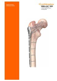
Cole Radiolucent Drill — Abbreviated <strong>Technique</strong><br />
24<br />
Step 1<br />
Attach the handle for<br />
use as left-handed<br />
or right-handed.<br />
Step 5<br />
Attach power drill to the<br />
Cole Radiolucent Drill.<br />
Tighten with a<br />
T-handled chuck key.<br />
Step 9<br />
Rotate the Cole<br />
Radiolucent Drill<br />
parallel or in line<br />
with the C-arm.<br />
Step 2<br />
Select the proper drill bit size<br />
and insert tapered end into<br />
the drill.<br />
Step 6<br />
Place drill bit onto<br />
the skin.<br />
Step 10<br />
Verify concentric position of the<br />
drill bit in the hole of the nail<br />
and two opaque rings. Drill<br />
through bone.
Step 3<br />
Place the locking cap<br />
over the drill bit with<br />
one hand while<br />
preventing rotation of<br />
the hollow tube with<br />
the other hand.<br />
Step 7<br />
Use image<br />
intensification<br />
to verify<br />
placement<br />
in the center<br />
of the<br />
perfect circle.<br />
Step 11<br />
After drilling, slide the screw<br />
length sleeve over the drill bit. Read<br />
correct screw length from top of screw<br />
length sleeve.<br />
Step 4<br />
Use the T-handled<br />
chuck key over the<br />
chuck end of the<br />
Cole Radiolucent Drill<br />
to prevent the shaft<br />
from rotating. Tighten<br />
the locking cap.<br />
Remove T-handled<br />
chuck key.<br />
Step 8<br />
After making an incision to<br />
bone and placing the drill bit<br />
on bone, center bit within the<br />
perfect circle with long axis<br />
of bit perpendicular to long<br />
axis of nail.<br />
Step 12<br />
Remove drill. Insert<br />
correct size bone screw.<br />
25
<strong>IMHS</strong> Removal<br />
Remove both the 4.5 mm distal locking screws with<br />
the Hexdriver.<br />
Loosen the Set Screw (HN-1202), using the 75 in./lb.<br />
Torque Wrench and Universal Set Screwdriver<br />
enough so that the sleeve and lag screw can pass<br />
through the nail's hole. The set screw does not have<br />
to be fully removed.<br />
Remove the Compressing Screw (12-1116) from the<br />
end of the lag screw with the Hexdriver.<br />
Attach the Lag Screw Insertion Wrench onto the lag<br />
screw and engage the Stabilizer Bar. The centering<br />
sleeve (HN-1200) will come out with the lag screw.<br />
Note: If difficulty is expected, use the Round<br />
T-Wrench (11-0048) instead of the Insertion Wrench.<br />
Attach the Removal Bolt to the proximal end of the<br />
nail using the 11/16" Universal Socket Wrench.<br />
Screw the Driver/Extractor Tube into the end of the<br />
Removal Bolt. Use the Slotted Hammer to remove the<br />
nail. Note: For difficult cases, attach the R-T Slide<br />
Hammer (11-2011) to the removal bolt instead of the<br />
Driver/Extractor Tube.<br />
26<br />
Removal<br />
Bolt<br />
Driver/Extractor<br />
Tube
Catalog Information – Implants<br />
<strong>IMHS</strong> Standard Lag Screws<br />
Thread Diameter: 1/2" (12.7 mm)<br />
Thread Length: 21.0 mm<br />
Root Diameter: 9.0 mm<br />
Cat. No. Length Cat. No. Length<br />
12-1100 55 mm 12-1109 100 mm<br />
12-1101 60 mm 12-1110 105 mm<br />
12-1102 65 mm 12-1111 110 mm<br />
12-1103 70 mm 12-1112 115 mm<br />
12-1104 75 mm 12-1113 120 mm<br />
12-1105 80 mm 12-1114 125 mm<br />
12-1106 85 mm 12-1176 130 mm<br />
12-1107 90 mm 12-1177 135 mm<br />
12-1108 95 mm 12-1178 140 mm<br />
NOTE: Do not use AMBI/CLASSIC 55, 60, or 65 mm lag screws with<br />
<strong>IMHS</strong>. These sizes are too short to work effectively with this device.<br />
AMBI Clip<br />
Cat. No. 12-1115<br />
27
Compression Screws<br />
Cat. No. Length Cat. No. Length<br />
12-1116 19 mm 12-1117 28.5 mm<br />
4.5 mm Self-Tapping Cortical Bone Screws<br />
Head Diameter: 8.0 mm<br />
Major Thread Diameter: 4.5 mm<br />
Root Diameter: 3.2 mm<br />
Cat. No. Length Cat. No. Length<br />
7112-9216 16 mm 7112-9242 42 mm<br />
7112-9218 18 mm 7112-9244 44 mm<br />
7112-9220 20 mm 7112-9246 46 mm<br />
7112-9222 22 mm 7112-9248 48 mm<br />
7112-9224 24 mm 7112-9250 50 mm<br />
7112-9226 26 mm 7112-9252 52 mm<br />
7112-9228 28 mm 7112-9254 54 mm<br />
7112-9230 30 mm 7112-9256 56 mm<br />
7112-9232 32 mm 7112-9258 58 mm<br />
7112-9234 34 mm 7112-9260 60 mm<br />
7112-9236 36 mm 7112-9262 62 mm<br />
7112-9238 38 mm 7112-9264 64 mm<br />
7112-9240 40 mm<br />
<strong>IMHS</strong> Compression Hip Screw<br />
Standard Nails<br />
Cat. No. Size<br />
7116-3010 10 mm x 21 cm x 130°<br />
7116-3510 10 mm x 21 cm x 135°<br />
HN-3012 12 mm x 21 cm x 130°<br />
HN-3512 12 mm x 21 cm x 135°<br />
HN-3014 14 mm x 21 cm x 130°<br />
HN-3514 14 mm x 21 cm x 135°<br />
HN-3016 16 mm x 21 cm x 130°<br />
HN-3516 16 mm x 21 cm x 135°<br />
28
Long Nails<br />
Cat. No. Size<br />
7116-3034R 10 mm x 34 cm x 130°<br />
7116-3034L 10 mm x 34 cm x 130°<br />
7116-3038R 10 mm x 38 cm x 130°<br />
7116-3038L 10 mm x 38 cm x 130°<br />
7116-3042R 10 mm x 42 cm x 130°<br />
7116-3042L 10 mm x 42 cm x 130°<br />
7116-3534R 10 mm x 34 cm x 135°<br />
7116-3534L 10 mm x 34 cm x 135°<br />
7116-3538R 10 mm x 38 cm x 135°<br />
7116-3538L 10 mm x 38 cm x 135°<br />
7116-3542R 10 mm x 42 cm x 135°<br />
7116-3542L 10 mm x 42 cm x 135°<br />
7116-6034L 12 mm x 34 cm x 130°<br />
7116-6034R 12 mm x 34 cm x 130°<br />
7116-6038L 12 mm x 38 cm x 130°<br />
7116-6038R 12 mm x 38 cm x 130°<br />
7116-6042L 12 mm x 42 cm x 130°<br />
7116-6042R 12 mm x 42 cm x 130°<br />
7116-6134L 12 mm x 34 cm x 135°<br />
7116-6134R 12 mm x 34 cm x 135°<br />
7116-6138L 12 mm x 38 cm x 135°<br />
7116-6138R 12 mm x 38 cm x 135°<br />
7116-6142L 12 mm x 42 cm x 135°<br />
7116-6142R 12 mm x 42 cm x 135°<br />
(R and L after Cat. No. indicates right or left.)<br />
<strong>IMHS</strong> Centering Sleeve & Set Screw<br />
Cat. No. Description<br />
HN-1200 Centering Sleeve<br />
HN-1202 Set Screw<br />
<strong>IMHS</strong> Nail Cap<br />
Cat. No. 12-2672<br />
29
Guide Pin<br />
2.4 mm<br />
Cat. No. 41-0236<br />
Twist Drill<br />
3.5 mm<br />
Cat. No. 7111-0045<br />
Bone Screw Tap for 4.5 mm<br />
Self-Tapping Screws<br />
Cat. No. 11-0077<br />
Bone Screw Tap for 4.5 mm<br />
Nonself-Tapping Screws<br />
Cat. No. 7111-0070<br />
Bone Screw Length Gauge<br />
Cat. No. 41-3500<br />
Screw Pickup<br />
Cat. No. 7111-5085<br />
Self-Holding Hex Screwdriver<br />
Cat. No. 7111-0026<br />
Hex Screwdriver<br />
Cat. No. 11-5035<br />
30
Catalog Information – Nail Instruments<br />
Curved Awl<br />
Cat. No. 21-6600<br />
Tissue Protector<br />
with Guide Pin Centering Sleeve<br />
(for use with the Proximal Reamer)<br />
Cat. No. 7115-2114<br />
3.2 mm x 353 mm Tip<br />
Threaded Guide Pin<br />
Cat. No. 11-5163<br />
Proximal Reamer<br />
Cat. No. 7115-2112<br />
Trial Handle<br />
Cat. No. 11-5183<br />
Trial<br />
Cat. No. Size<br />
7115-2110 10 mm<br />
11-5185 12 mm<br />
11-5186 14 mm<br />
Drill Guide<br />
(Shown Assembled)<br />
(Consisting of Guide, Handle, Drill<br />
Guide Bolt, Angle Guide<br />
Attachment Bolt)<br />
Cat. No. 7115-2124<br />
Replacement parts available for Cat.<br />
No. 7115-2124:<br />
Drill Guide Bolt: Cat. No. 7115-2132<br />
Angle Guide Attachment Bolt: Cat. No. 7115-<br />
2134<br />
Combination Lag Screw and<br />
Barrel/Sleeve Reamer<br />
Cat. No. 7115-2136<br />
31
32<br />
Driver<br />
Cat. No. 11-5160<br />
Angle Guide Attachment<br />
Cat. No. Angle<br />
11-5170 130°<br />
11-5171 135°<br />
11/16" Universal Socket Wrench<br />
Cat. No. 11-5177<br />
9/16" Open End Wrench<br />
Cat. No. 11-0566<br />
Silver Drill Sleeve<br />
Cat. No. Size<br />
11-5161 14 cm<br />
7115-2116 16 cm<br />
Guide Pin Sleeve<br />
Cat. No. 11-5164<br />
3.2 mm x 353 mm Tip<br />
Threaded Guide Pin<br />
Cat. No. 11-5163<br />
Lag Screw Length Gauge<br />
Cat. No. 11-5162<br />
Lag Screw Shaft Reamer<br />
Cat. No. 11-5166<br />
Sleeve Reamer<br />
Cat. No. 11-5182<br />
Lag Screw Tap<br />
Cat. No. 7115-2118
Lag Screw Insertion<br />
Wrench Assembly<br />
(Shown Assembled)<br />
(Consisting of Handle, Lag Screw<br />
Retaining Rod, Wrench Shaft)<br />
Cat. No. 11-5176<br />
Replacement Retaining Rod<br />
for the <strong>IMHS</strong> Lag Screw<br />
Insertion Wrench<br />
Cat. No. 7111-5078<br />
Sleeve Inserter<br />
Cat. No. 11-5165<br />
Slotted Hammer<br />
Cat. No. 11-5175<br />
Universal Set Screwdriver<br />
Cat. No. 7115-2122<br />
75 in./lb. Torque Wrench<br />
Cat. No. 11-5188<br />
3.5 mm Black Drill Sleeve<br />
Cat. No. 11-2086<br />
8.0 mm Green Drill Sleeve<br />
Cat. No. 11-2012<br />
T-Handle Jacob’s Chuck<br />
Cat. No. 11-0257<br />
3.5 mm Trocar<br />
Cat. No. 11-2085<br />
33
34<br />
3.5 mm Twist Drill<br />
Cat. No. 7115-2128<br />
Bone Screw Length Gauge<br />
Cat. No. 7115-2126<br />
Hexdriver<br />
Cat. No. 11-2088<br />
Screw Pickup<br />
Cat. No. 7111-5085<br />
Removal Bolt<br />
Cat. No. 11-5174<br />
Driver/Extractor Tube<br />
Cat. No. 11-2008<br />
Lag Screw/Barrel Sleeve Reamer<br />
Cat. No. 7115-2136<br />
Rad Guide<br />
130 Deg. Cat. No. 7115-2138<br />
135 Deg. Cat. No. 7115-2139<br />
Retain Rod for Lag Screw Removal<br />
Cat. No. 7115-2142<br />
<strong>IMHS</strong> Guide, 18cm<br />
130 Deg. Cat. No. 7115-2140<br />
135 Deg.<br />
(Not shown)<br />
Cat. No. 7115-2141<br />
<strong>IMHS</strong> Drill Guide Bolt<br />
Cat. No. 7115-2132<br />
(Not shown)<br />
Angle Guide Attachment Bolt<br />
Cat. No. 7115-2134<br />
(Not shown)
<strong>IMHS</strong> Instrument Sterilizing Case #1<br />
(with Tray Lid and Insert)<br />
Cat. No. 7115-2102<br />
<strong>IMHS</strong> Instrument Sterilizing Case #2<br />
(with Tray Lid)<br />
Cat. No. 7115-2106<br />
4.5 mm Bone Screw Caddy<br />
NOTE: This caddy holds 6 each of the most widely<br />
used bone screw sizes. They are 20–48 mm in<br />
2 mm increments.<br />
Cat. No. 7115-2108<br />
Templates<br />
Standard <strong>IMHS</strong> Templates<br />
Cat. No. 7118-0342<br />
(Not shown)<br />
Long <strong>IMHS</strong> Templates<br />
Cat. No. 7118-0298<br />
(Not shown)<br />
35
Orthopaedics<br />
Smith & Nephew, Inc.<br />
1450 Brooks Road<br />
Memphis, TN 38116<br />
USA<br />
Telephone: 901-396-2121<br />
Information: 1-800-821-5700<br />
Orders/inquiries: 1-800-238-7538<br />
The following statement is required by the U.S. FDA: WARNING: This device is not<br />
approved for screw attachment or screw fixation to the posterior elements (pedicles)<br />
of the cervical, thoracic or lumbar spine.<br />
Trademark of Smith & Nephew. Certain Marks Reg. U.S. Pat. & TM. Off.<br />
www.smith-nephew.com<br />
30013303002 7118-0934 11/04