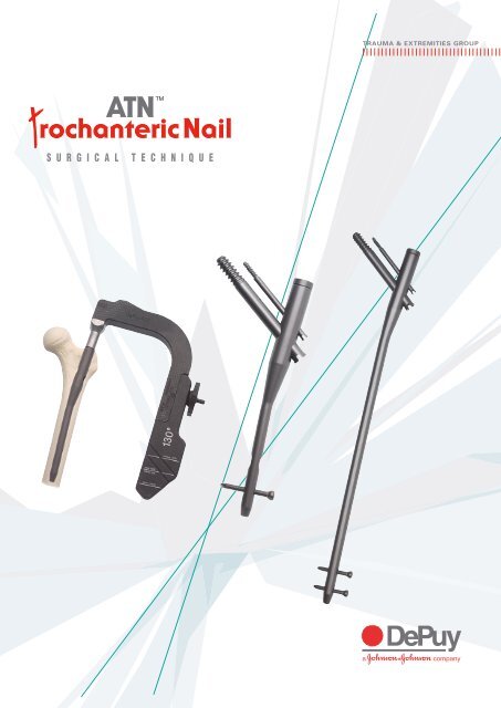
ATN Trochanteric femoral nail
ATN Trochanteric femoral nail
ATN Trochanteric femoral nail

Create successful ePaper yourself
Turn your PDF publications into a flip-book with our unique Google optimized e-Paper software.
S U R G I C A L T E C H N I Q U E<br />
TRAUMA & EXTREMITIES GROUP
TABLE OF CONTENTS<br />
<strong>ATN</strong> NAIL SYSTEM DESIGN RATIONALE<br />
INDICATIONS/CONTRAINDICATIONS<br />
PREOPERATIVE PLANNING AND<br />
PATIENT POSITIONING<br />
NAIL INSERTION<br />
PROXIMAL LOCKING<br />
DISTAL LOCKING<br />
NAIL REMOVAL<br />
LONG NAIL TECHNIQUE STEPS 1-9<br />
PRODUCT ORDERING INFORMATION<br />
INSTRUMENTS<br />
IMPLANT SCHEMATIC<br />
1<br />
2<br />
3<br />
5<br />
8<br />
14<br />
16<br />
18<br />
22<br />
24<br />
26
<strong>ATN</strong> NAIL SYSTEM DESIGN RATIONALE<br />
The <strong>ATN</strong> <strong>Trochanteric</strong> Nail System treats a wide range of proximal <strong>femoral</strong> fracture<br />
indications using a single set of user-friendly instruments. The <strong>ATN</strong> system is designed<br />
to provide improved resistance to cut-out and improved rotational control as compared<br />
to single screw fixation (i.e. one lag screw). The result is true rotational stability.<br />
The <strong>nail</strong>, manufactured from TiMAX anodized titanium alloy for high fatigue strength and<br />
optimal stress transfer, can be used in conjunction with a single lag screw and/or an optional<br />
anti-rotation (AR) screw to maintain re-alignment of unstable fractures. The screws are closely<br />
spaced so most patient anatomies can accommodate both if required. An extensive range of<br />
neck/shaft angles, distal diameters and <strong>nail</strong> lengths – combined with the smaller proximal <strong>nail</strong><br />
diameter – allow the surgeon to achieve a close match for each patient’s anatomy. Reduced<br />
proximal <strong>nail</strong> height, together with a range of end cap sizes, allows the <strong>nail</strong> to<br />
be correctly seated and remain flush with the greater trochanter.<br />
The instruments for this procedure are colour-coded and laid out for easy<br />
identification and correct selection. The radiolucent insertion and targeting jig<br />
allows good fluoroscopic visualisation of the <strong>nail</strong> and anatomy for proximal lag<br />
screw, anti-rotation screw and distal static and dynamic screw targeting.<br />
TiMAX is DePuy Trauma and Extremities Group’s name for the titanium alloy Ti-6A1-4V<br />
treated* with a proprietary surface treatment. The increased surface hardness of TiMax<br />
permits these components to slide more easily relative to one another. The surgical goal<br />
for hip fixation is to achieve continuous compressive micromotion at the fracture site.<br />
The ability of the lag screw to effectively slide within the hip screw barrel is critical to<br />
achieve this goal.<br />
* TiMax = Ti-6A1-4V + Proprietary Surface Treatment<br />
IMPLANT SCHEMATIC<br />
End Cap<br />
0 - 25 mm<br />
Sterile: End Cap9032-08XXX<br />
End Cap<br />
0 - 25 mm 0 - 25 mm<br />
Sterile: 9032-08-0XX<br />
Sterile: 9032-08XXX<br />
End Cap<br />
0 - 25 mm<br />
Sterile: 9032-08-0XX<br />
20.25 mm<br />
Solid Cortical Bone Screw ø 4.5 mm<br />
30 - 60 mm<br />
Sterile: 8050-45XXX<br />
Solid Solid Cortical Cortical Bone Bone Screw Screw ø 4.5 mm ø 4.5 mm<br />
30 - 60 mm30<br />
- 60 mm<br />
Sterile: Solid Cortical Sterile: 8050-45XXX<br />
8050-45-0XX Bone Screw ø 4.5 mm<br />
30 - 60 Non mmSterile:<br />
14022-XX<br />
Anti-Rotation Screw ø 5 mm<br />
Sterile: 8050-45XXX 60 - 100 mm<br />
Sterile: 9032-05XXX<br />
Anti-Rotation Screw ø 5 mm<br />
60 - 100 mm<br />
Sterile: Anti-Rotation 9032-05XXX Screw ø 5 mm<br />
60 - 100 mm<br />
Sterile: 9032-05XXX<br />
Anti-Rotation Screw ø 5 mm<br />
60 - 100 mm<br />
Sterile: 9033-05-XXX<br />
Lag Screw ø 10.5 mm<br />
60 - 120 mm<br />
Sterile: 9032-11XXX<br />
Lag Screw ø 10.5 mm<br />
60 - 120 mm<br />
Lag Screw ø 10.5 mm<br />
Sterile: Lag Screw 9032-11XXX ø 10.5 mm<br />
60 - 120 mm<br />
60 - 120 Sterile: mm9033-11-XXX<br />
Sterile: 9032-11XXX<br />
See page 22 for full product code details<br />
125˚<br />
130˚<br />
135˚<br />
5˚<br />
ø16 mm<br />
20 mm<br />
43 mm<br />
180 mm (Short Nail)<br />
200 mm (Standard Nail)<br />
40 mm<br />
Short Nail<br />
180 mm<br />
Standard Nail<br />
200 mm<br />
ø 9 mm<br />
ø 11 mm<br />
ø 13 mm<br />
320 mm - 440 mm (Long Nail)<br />
Long Nail<br />
320 - 420 mm<br />
1<br />
<strong>ATN</strong> DESIGN
2<br />
INDICATIONS/CONTRAINDICATIONS<br />
The <strong>ATN</strong> Nail System* is designed for antegrade trochanteric insertion to treat the following fractures:<br />
<strong>ATN</strong> (180 AND 200 MM)<br />
Indications<br />
The <strong>ATN</strong> <strong>Trochanteric</strong> Nail System is intended<br />
to treat stable and unstable proximal fractures<br />
of the femur including pertrochanteric fractures,<br />
intertrochanteric fractures, high subtrochanteric<br />
fractures and combinations<br />
of these fractures.<br />
Contraindications<br />
• Low subtrochanteric fractures<br />
• Femoral shaft fractures<br />
• Isolated or combined medial <strong>femoral</strong><br />
neck fractures<br />
• 9 mm Nail is intended for use<br />
with smaller patients<br />
LONG <strong>ATN</strong> (320 - 420 MM)<br />
Indications<br />
The <strong>ATN</strong> <strong>Trochanteric</strong> Long Nail System is<br />
also indicated to treat pertrochanteric fractures<br />
associated with shaft fractures, pathologic<br />
fractures in osteoporotic bone of the trochanteric<br />
and diaphyseal areas, long subtrochanteric<br />
fractures, ipsilateral <strong>femoral</strong> fractures, proximal<br />
or distal non-unions and malunions and<br />
revision procedures.<br />
Contraindications<br />
• Isolated or combined medial <strong>femoral</strong><br />
neck fractures<br />
• 9 mm Nail is intended for use<br />
with smaller patients<br />
Please note: Bone screws referenced in this material are not approved for screw attachment<br />
or fixation to the posterior elements (pedicles) of the cervical thoracic or lumbar spine.<br />
* System includes short, 180 mm; standard, 200 mm; and long, 320 - 420 mm <strong>nail</strong>, in 20 mm increments.
PREOPERATIVE PLANNING<br />
The <strong>ATN</strong> <strong>Trochanteric</strong> Nail System offers the surgeon<br />
a comprehensive set of preoperative templates for use<br />
with radiographs at 15 percent magnification, in the true<br />
anterior/posterior plane. Laid over the uninjured side,<br />
these can be used to predict <strong>nail</strong> and screw size.<br />
Preoperative templating provides a guide for appropriate<br />
<strong>nail</strong> length and neck angle, as well as an indication of<br />
the lag screw position, angle and optional AR screw.<br />
Select a template with the appropriate neck angle<br />
125˚, 130˚** or 135˚ and overlay to establish the distal<br />
position of the <strong>nail</strong> along the long axis of the femur.<br />
Establish the lag screw position by adjusting the inferior/<br />
superior template position so that the lag screw is in the<br />
central to lower third of the <strong>femoral</strong> neck. Orient the lag<br />
screw in line with the axis of the <strong>femoral</strong> neck. Position the<br />
lag screw distal tip approximately 5 - 10 mm from the edge of<br />
the subchondral bone of the <strong>femoral</strong> head. This will<br />
estimate the lag screw length required.<br />
Note: For unstable fractures lacking a medial buttress<br />
support and a high degree of osteopenia, it is advised<br />
to insert the lag screw 10 mm from subchondral bone.<br />
** 130º is the most frequently used neck angle.<br />
3<br />
PREOPERATIVE PLANNING AND PATIENT POSITIONING
4<br />
PREOPERATIVE PLANNING AND PATIENT POSITIONING<br />
Optimum Position of<br />
Lag and AR Screws<br />
Preoperative Planning, continued<br />
If an AR screw is required, position the lag screw in<br />
the lower third of the <strong>femoral</strong> neck, with the<br />
anti-rotation screw within the superior third of<br />
the neck. Typically the anti-rotation screw should be<br />
15 – 20 mm shorter than the lag screw.<br />
Take care to ensure that the threaded tip of<br />
the anti-rotation screw is beyond the fracture.<br />
Distal locking options may be considered<br />
pre- or intra-operatively.<br />
10 - 15º<br />
Adduction<br />
Patient Positioning<br />
Place the patient in the supine position on a<br />
fracture table or radiolucent imaging table. Lateral<br />
access to the proximal femur is required. For the<br />
operation, access an image intensifier,<br />
or ‘C-arm’, to obtain fluoroscopic AP and lateral<br />
views during preoperative preparation (reduction)<br />
and throughout the procedure for <strong>nail</strong><br />
insertion and locking, and for anteversion<br />
alignment. The affected leg must be adducted and<br />
the trunk securely bent toward the opposite side.<br />
The contralateral leg may be flexed at the hip<br />
or scissored below the affected leg.<br />
Fracture Reduction<br />
Fluoroscopy must be used to verify<br />
proper fracture reduction.<br />
• Anatomic reduction is essential prior<br />
to incision.<br />
• Surgeon must avoid varus malreduction.<br />
• Rotation will depend on level of fracture.<br />
Initial Incision<br />
Make an incision proximal to the trochanteric<br />
region, in line with the <strong>femoral</strong> axis. Place<br />
a self-locking retractor to open the wound.<br />
Divide the fascia lata along its fibres.<br />
Access the tip of the greater trochanter.
Femoral Entry Preparation<br />
<strong>Trochanteric</strong><br />
Entry Point<br />
Opening the Femur Option 1:<br />
Cannulated Entry Reamer (One-step 17 mm)<br />
Attach the standard 3.2 mm guide wire to the<br />
guide wire grip handle or power source and pass it<br />
down through the trochanter into the centre of the<br />
<strong>femoral</strong> canal. Position entry at or slightly lateral to<br />
the tip of the trochanter.<br />
Verify the position using fluoroscopic AP and<br />
lateral views. Attach the one-step cannulated<br />
entry reamer 1 * to the power source and pass<br />
it over the guide wire through the tubular skin<br />
protector. Use it to create an entry through the<br />
greater trochanter into the <strong>femoral</strong> canal.<br />
Opening the Femur Option 2:<br />
Large Pointed Awl 2<br />
Use the large pointed awl 2 to make an<br />
entry point just at the tip of the greater trochanter<br />
centrally anterior to posterior. The entry angle<br />
should correspond to the proximal part of the<br />
implant: 5 degrees toward the long axis of the<br />
femur. Verify the position and entry angle of the AP<br />
and lateral view using fluoroscopy. Introduce the<br />
awl, with a rotating motion, to at least half<br />
its blade length. This allows the reamer clear<br />
passage. Place a standard 3.2 mm guide wire<br />
through the opening into the femur, allowing<br />
introduction of the one-step cannulated<br />
entry reamer 1 .<br />
* Relates to numbered instrumentation on the fold-out on page 24 at the end of this document.<br />
Femoral Preparation<br />
Opening the Femur Option 3:<br />
Cannulated Awl<br />
Attach a standard 3.2 mm guide wire to the<br />
guide wire grip handle or power source and<br />
pass it down through the trochanter into the<br />
<strong>femoral</strong> canal. Pass the cannulated awl 2a over<br />
the guide wire and introduce, with a rotating<br />
motion, to at least half its blade length.<br />
5<br />
NAIL INSERTION
6<br />
NAIL INSERTION<br />
Proximal Reaming<br />
AP and lateral fluoroscopy are mandatory<br />
to confirm depth and reaming position.<br />
Attach the cannulated entry reamer 1 to the<br />
T-handle quick couple 6 or powersource<br />
and pass it over the guide wire and through the<br />
tubular skin protector. It is essential to ream until<br />
at least the reamer’s proximal shaft passes within<br />
the greater trochanter’s cortical bone (the reamer<br />
nose’s cylindrical length matches the implant’s<br />
proximal portion length, above its tapered section).<br />
If access for reaming is inhibited by the soft<br />
tissues, attach the quick-couple power adaptor<br />
8 to the reamer to increase the shaft length.<br />
The 17 mm-diameter reamer is 1 mm greater<br />
in diameter than the <strong>nail</strong> to allow free passage<br />
of the <strong>nail</strong> within the proximal femur.<br />
Using standard reamers<br />
If using standard reamers, reaming stops at<br />
the appropriate depth and is completed with<br />
a 17 mm-diameter reamer, at least to<br />
the level of the lesser trochanter.<br />
Alignment of<br />
Proximal Targeting<br />
Jig Assembly<br />
(130º neck angle most commonly used)<br />
Select a targeting module 7 that corresponds to<br />
the neck angle determined during preoperative<br />
templating. Attach it to the insertion jig 4 and<br />
secure it using the targeting module locking nut 5 .<br />
Screw the locking bolt 9 using the T-handle<br />
locking wrench 3 , and pass it through<br />
the insertion jig nose.
Alignment<br />
Groove<br />
Nail Flat<br />
Jig Assembly<br />
Locate the selected <strong>nail</strong> on the insertion jig lug.<br />
Align the flat on its proximal tip with the groove<br />
on the jig’s outside face so that the distal tip is<br />
oriented toward the targeting module. Once in<br />
place, use the T-handle locking wrench 3 to tighten<br />
the locking bolt 9 and secure the implant to the jig.<br />
Check the assembly prior to <strong>nail</strong> introduction.<br />
Pass the lag screw sheath10 through the targeting<br />
module. Proper assembly will direct the lag screw<br />
drill14 through the sleeve and through the proximal<br />
lag screw hole in the assembled <strong>nail</strong>. Pass the<br />
distal sheath26 and the 3.8-mm calibrated drill<br />
29 through the targeting module to ensure<br />
correct alignment with the distal locking holes.<br />
DO NOT HAMMER THE INSERTION JIG<br />
Nail Introduction<br />
Introduce the <strong>nail</strong>, attached to the jig<br />
assembly, into the proximal femur by hand.<br />
Passage over the guide wire is optional.<br />
Do not hammer the insertion jig. Do not<br />
use a sliding hammer with the short <strong>nail</strong>s.<br />
It is only required during <strong>nail</strong> extraction.<br />
If the <strong>nail</strong> is difficult to insert, or if fluoroscopy<br />
indicates impingement between the <strong>nail</strong> tip and the<br />
medial and anterior cortices, carry out additional<br />
proximal reaming to ease the <strong>nail</strong> introduction.<br />
If extra distal reaming is required, follow a<br />
standard reaming technique using a ball<br />
nose guide wire and exchange tube.<br />
7<br />
NAIL INSERTION
8<br />
PROXIMAL LOCKING<br />
Nail Introduction<br />
As the <strong>nail</strong> is inserted, check the insertion<br />
depth, using fluoroscopy. This ensures correct<br />
lag screw hole alignment with the planned<br />
position for the screw in the <strong>femoral</strong> neck.<br />
This is achieved by laying a guide wire over<br />
the targeting module and across the femur.<br />
The guide wire should be aligned with the<br />
appropriate mark on the targeting module,<br />
across the appropriate screw hole in the <strong>nail</strong><br />
and align with the predicted screw position<br />
in the femur. If not, the <strong>nail</strong> should be moved<br />
proximally or distally until it's position is correct.<br />
Maintenance of the reduction must be<br />
confirmed. Once the <strong>nail</strong> is positioned,<br />
introduce the lag screw guide wire.<br />
Lag Screw Guide Pin Introduction<br />
Insert the lag screw sheath10 through the lag<br />
screw hole in the insertion jig assembly. Pass the<br />
trochar11 through the sheath and make a suitable<br />
incision where the trochar contacts the skin.<br />
Push the trochar and sheath through the tissue<br />
until firm contact is made with the lateral <strong>femoral</strong><br />
cortex. Gently tap the trochar tip with a hammer<br />
to create a starting point for the guide wire in<br />
the cortex. View its position under fluoroscopy.<br />
Remove the trochar while the sheath is held<br />
against the cortex. Screw the guide pin sheath<br />
12 into the lag screw sheath. If the cortical bone<br />
is particularly dense, pre-drill the cortices (using<br />
the lag screw drill14) to avoid bending the guide<br />
pin during insertion. Introduce the 3.2 mm guide<br />
pin under power through the sheath. Centrally<br />
align the pin within the lag screw hole in the <strong>nail</strong>,<br />
and drill into position under fluoroscopic<br />
guidance. Check the guide pin position within<br />
the centre of the <strong>femoral</strong> head and neck in<br />
both AP and lateral planes. Drill the guide pin to<br />
approximately 5 mm from subchondral bone.<br />
Note: If at any time a guide pin is<br />
bent, replace it immediately.
AR Guide Pin Placement<br />
If using the optional anti-rotation screw,<br />
leave the lag screw sheath and guide pin<br />
in place to maintain construct rigidity and<br />
ensure parallel screw positioning.<br />
Widen the incision and drive the anti-rotation<br />
sheath 20 and trochar 21 into firm contact with<br />
the lateral cortex. Gently tap the trochar<br />
tip with a hammer to create a starting<br />
point for the guide wire in the cortex.<br />
AR Guide Pin Placement<br />
Correct Sheath<br />
Orientation<br />
Note: The flat sections on the lag screw and<br />
anti-rotation screw sheaths must face each<br />
other (so that the coloured handles are at<br />
180º) to allow assembly into the insertion jig.<br />
Remove the trochar and insert the anti-rotation<br />
screw guide pin sheath 22 and screw it into the<br />
sleeve. If the cortical bone is particularly dense,<br />
pre-drill the cortices (using the anti-rotation screw<br />
drill 23) to avoid bending the guide pin during<br />
insertion. Pass the 2.5 mm guide pin through<br />
the sheath and drill into place. Check the guide<br />
pin position during placement in both AP and<br />
ML planes, and use fluoroscopy to ensure that<br />
it passes through the anti-rotation screw hole<br />
centre in the <strong>nail</strong> and is correctly positioned<br />
within the <strong>femoral</strong> neck and head. Insert the<br />
guide pin until its tip is 15 - 20 mm short of<br />
the lag screw guide wire tip and is at least 16<br />
mm beyond the fracture to allow firm fixation.<br />
9
10<br />
This difference represents<br />
the difference between the<br />
guide pin tip positions<br />
Screw Length Selection<br />
Select the screw length with the lag screw<br />
and anti-rotation screw sheaths<br />
and guide pins in place.<br />
• Firmly seat both sheaths onto the bone<br />
• The depth gauge 13 is located against the<br />
proximal face of each sheath with<br />
the guide pin sheaths in place<br />
• The depth gauge 13 measuring face<br />
arrow must point toward the sheath<br />
• Read the protruding length of the guide pin<br />
• System measures to the tip of the guide pin<br />
Note: The seperation in between the<br />
guide pin tips in the <strong>femoral</strong> head can<br />
be visualised from the seperation of the<br />
protruding pins from the instrument sheaths<br />
5 - 10 mm<br />
15 - 20 mm<br />
Screw Length Selection<br />
Lag Screw Selection<br />
The depth gauge indicates the guide pin<br />
length to its tip. Lag screw length is<br />
up to the surgeon’s discretion.<br />
Anti-rotation Screw Selection<br />
Determine the anti-rotation screw length<br />
using the depth gauge. No allowance<br />
for shortening is required.<br />
Once the lag and anti-rotation screw lengths have<br />
been determined, remove both guide<br />
pin sheaths.
Depth Stop Assembly<br />
Measurements taken<br />
here, i.e., 95 mm<br />
Assemble the depth stop15 front and back parts<br />
onto the lag screw drill14 separately. Pass the<br />
front piece over the drill first. Then pass the<br />
back piece over the drill until it locates in the<br />
previously decided depth groove. Lock the stop<br />
in place by tightening the front piece onto the<br />
back piece, ensuring the depth stop is secured.<br />
The figure in line with and half covered<br />
by the front face of the depth stop<br />
assembly, is the set drill depth.<br />
Tighten Depth Stop<br />
Lag Screw Drilling and Tapping<br />
Drive the assembly over the guide wire to its<br />
desired depth. Use fluoroscopy during drilling<br />
to check the position of the guide wire and<br />
ensure that it is not driven forward by the drill.<br />
Make a final check of the drill position, using<br />
fluoroscopy, before drill removal.<br />
If the bone is particularly dense, use a cannulated<br />
tap16 to cut a thread for the screw. Assemble the<br />
tap with the depth stop front and back parts in<br />
the same way as the lag screw. Then attach to<br />
the quick couple handle 6 and manually insert.<br />
11
12<br />
Lag Screw Insertion<br />
Pass the lag screw coupling rod18 through the lag<br />
screw insertion wrench17. Position the selected<br />
lag screw on the insertion wrench lugs and<br />
then screw the coupling rod to the lag screw.<br />
If fracture compression is anticipated, screw the<br />
compression nut19 onto the lag screw insertion<br />
wrench before the assembly is introduced<br />
to the femur. Zero compression is achieved<br />
when the thread on the insertion wrench aligns<br />
with ‘0’ in the compression nut window.<br />
Insert the lag screw assembly manually. When<br />
the insertion wrench abuts against the sleeve,<br />
the lag screw has reached its planned position.<br />
Note: The lateral end of the lag screw should<br />
not extend beyond the lateral cortex more<br />
than 1 cm.<br />
Note: For unstable fractures lacking a medial<br />
buttress support and a high degree of<br />
osteopenia, it is advised to insert the lag<br />
screw 10 mm from subchondral bone.<br />
Fracture Compression<br />
Clockwise rotation for<br />
compression<br />
Fracture compression can only be applied before<br />
the anti-rotation screw is inserted, without the antirotation<br />
sheath20 in place. Clockwise rotation of<br />
the compression nut19, while holding the lag screw<br />
insertion wrench handle17, applies compression.<br />
Each full rotation of the compression nut pulls the<br />
lag screw and <strong>femoral</strong> head<br />
2 mm distal/lateral. The compression applied<br />
is indicated in the gauge window. Take care to<br />
avoid pulling the lag screw from its engagement<br />
in the <strong>femoral</strong> head. It is recommended that no<br />
more than 4 - 6 mm of compression is applied.
Fully inserted guide pin<br />
System drills to start<br />
of AR screw thread<br />
Anti-rotation Screw Insertion<br />
Note: Always insert the anti-rotation<br />
screw after the lag screw.<br />
Remove both the anti-rotation guide pin sheath<br />
22 and guide pin. Pass the anti-rotation screw<br />
drill 23 through the anti-rotation sheath 20 and drill<br />
into the bone. Stop drilling when the required<br />
depth mark on the drill is aligned with the face<br />
of the anti-rotation sheath. At this point the tip<br />
of the drill will match the start of the threaded<br />
portion of the anti-rotation screw, not the depth<br />
to which the 2.5 mm guide pin tip was inserted.<br />
This calibrated depth preserves crucial bone stock<br />
for screw location and should not be exceeded.<br />
Note: Deciding drill depth by fluoroscopy will<br />
lead to incorrect placement and reduction of<br />
the bone stock for the anti-rotation screw.<br />
Again, if the bone is particularly dense, use a<br />
tap 24 to cut a thread for the screw. The antirotation<br />
tap does not have a depth stop. Use the<br />
depth markings on the shaft to guide insertion.<br />
Anti-rotation Screw Placement<br />
Place the selected anti-rotation screw on the<br />
insertion wrench 25. Attach the T-handle quick<br />
couple 6 to the insertion wrench and manually<br />
insert the assembly. When the shoulder of the<br />
insertion wrench abuts the sleeve, the antirotation<br />
screw has reached its planned position.<br />
Proximal locking is now complete. Remove<br />
both sheaths.<br />
13
14<br />
DISTAL LOCKING<br />
Distal Locking<br />
Choose static or dynamic distal locking.<br />
Select the appropriate targeting module hole that<br />
corresponds to the <strong>nail</strong> size implanted<br />
(180 or 200 mm). Locking options include<br />
static, dynamic, both or none.<br />
Distal Locking: Static<br />
Pass the assembled distal sheath 26 and<br />
trochar 27 through the appropriate static hole<br />
for the 180 or 200 mm rod. Make a small<br />
incision at the point of skin contact.<br />
Push the assembly through the soft<br />
tissue until firm contact is made with the<br />
lateral cortex and remove the trochar.<br />
Insert the 3.8 mm drill guide28 through the<br />
distal sheath and screw into the sleeve.
Distal Locking: Static<br />
Advance the 3.8 mm calibrated drill 29 through the<br />
drill guide. Stop drilling when the medial cortex<br />
is penetrated. Note the depth mark on the drill at<br />
the level of the drill guide, and remove the drill.<br />
Maintain contact of the distal sleeve on bone,<br />
especially for depth checking or assessment.<br />
An optional depth gauge, which passes<br />
through the drill guide may provide a final<br />
depth check. Select a 4.5 mm diameter<br />
screw, corresponding in length to the depth<br />
noted on the drill level. Use the hexagonal<br />
screwdriver30 to introduce the screw through<br />
the distal sheath and drive it until its tip passes<br />
through the far cortex. Remove the sheath.<br />
The <strong>nail</strong> is statically used at the surgeon’s<br />
discretion. The second distal (dynamic)<br />
screw may also be inserted.<br />
Distal Locking: Dynamic<br />
Measurements<br />
taken here<br />
Pass the distal sheath 26 through the<br />
appropriate 200 or 180 mm dynamic hole<br />
in the targeting module. Pass the trochar<br />
through the distal sheath and make a stab<br />
incision at the point of skin contact.<br />
Push the assembly through the soft tissues<br />
until firm contact is made with the lateral<br />
cortex. Remove the trochar. Introduce the drill<br />
guide through the distal sheath. Introduce the<br />
3.8 mm drill and advance through the lateral<br />
cortex. Stop drilling when the far cortex is<br />
penetrated. Note the depth mark on the drill,<br />
at the level of drill guide, and remove the drill.<br />
Distal static or dynamic locking is now<br />
complete. Verify locking screw position<br />
using AP and lateral fluoroscopy image.<br />
15
16<br />
NAIL REMOVAL<br />
End Cap Insertion<br />
Unscrew the locking bolt 9 on the insertion<br />
jig assembly 4 using the T-handle locking<br />
wrench 3 . Remove the assembly.<br />
Use fluoroscopy to assess the depth from the tip<br />
of the greater trochanter to the proximal tip of the<br />
<strong>nail</strong> and select the corresponding size end cap.<br />
Screw the end cap into the proximal end of<br />
the <strong>nail</strong> using the T-handle locking wrench 3 .<br />
Rehabilitation<br />
For intertrochanteric fractures, early postoperative<br />
weight bearing is generally allowed.<br />
Nail Removal<br />
Open the incision and gain clear access to the <strong>nail</strong><br />
end cap. Unscrew the end cap using the<br />
T-handle locking wrench 3 .<br />
Assemble the insertion jig 4 and the appropriate<br />
targeting module 7 and secure using the<br />
locking nut. (Use this same module for <strong>nail</strong><br />
insertion. The procedure for selection and<br />
assembly is described on pages 6 and 7.)<br />
Screw the locking bolt 9 into and pass<br />
it through the insertion jig nose. Use the<br />
locking wrench to tighten the locking bolt<br />
and secure the implant to the jig.<br />
Pass the lag screw sheath 10 through the<br />
targeting module and make a stab incision<br />
at the previous incision scar.<br />
Pass the lag screw trochar11 through the lag screw<br />
sheath to the lateral cortex. Remove the trochar.<br />
Assemble the lag screw coupling rod18 and the<br />
insertion wrench17. Insert the assembly through the<br />
sheath and screw the coupling rod, clockwise to<br />
lock to the lag screw. Rotate the inserter wrench<br />
handle counterclockwise to extract the lag screw.
ROTATE COUNTERCLOCKWISE ONLY USE HAMMER FOR NAIL EXTRACTION<br />
AR Screw Removal<br />
Access the anti-rotation screw head in the same<br />
way as the lag screw, using the dedicated antirotation<br />
screw instruments. Pass the anti-rotation<br />
screw wrench25 through the sheath20 and locate<br />
it on the distal tip of the anti-rotation screw.<br />
Counterclockwise rotation locks the wrench<br />
to the screw. Extract the screw by<br />
continued counterclockwise turns.<br />
Distal Screw Removal<br />
Extract the distal screws in the same way<br />
as the two proximal screws, using the<br />
dedicated distal screw instruments.<br />
Nail Removal<br />
The <strong>nail</strong> remains attached to the insertion jig for<br />
removal. Extraction should not require excessive<br />
force, but, if necessary, screw a sliding hammer to<br />
the jig at the location position marked. Ensure that<br />
the sliding hammer rod is fully threaded into the<br />
insertion jig before applying force.<br />
Do not hammer the insertion jig. Only use<br />
impact/removal assembly (sliding hammer31<br />
and impact/removal rod32) for <strong>nail</strong> extraction.<br />
If the targeting insertion jig cannot be<br />
fitted to the <strong>nail</strong>, use the extraction<br />
adaptor 33 to remove the <strong>nail</strong>. Connect<br />
the extraction adaptor to the <strong>nail</strong> before<br />
screw removal. Locate the proximal and<br />
distal screws and remove without the aid<br />
of the insertion jig. Screw the extraction<br />
adaptor into the <strong>nail</strong>ʼs proximal end and<br />
then screw the sliding hammer rod into the<br />
adaptor. Apply force to remove the <strong>nail</strong>.<br />
Once the screws and <strong>nail</strong> have been<br />
extracted, close the wounds.<br />
17
18<br />
LONG NAIL TECHNIQUE<br />
Step 1: Preoperative Planning<br />
The <strong>ATN</strong> <strong>Trochanteric</strong> Nail System offers the<br />
surgeon a comprehensive set of preoperative<br />
templates for use with radiographs at 15 percent<br />
magnification, in the true anterior/posterior<br />
plane. Laid over the uninjured side, these can<br />
be used to predict <strong>nail</strong> and screw size.<br />
Preoperative templating provides a guide<br />
for appropriate <strong>nail</strong> length and neck angle,<br />
as well as an indication of the lag screw<br />
position, angle and optional AR screw.<br />
Use the template to establish the distal position<br />
of the <strong>nail</strong> along the long axis of the femur.<br />
Establish the lag screw position by adjusting the<br />
inferior/ superior template position so that the lag<br />
screw is in the central to lower third of the <strong>femoral</strong><br />
neck. Orient the lag screw in line with the axis of<br />
the <strong>femoral</strong> neck. Position the lag screw distal tip<br />
approximately 5 - 10 mm from the edge of the<br />
subchondral bone of the <strong>femoral</strong> head. This will<br />
estimate the lag screw length required.<br />
Note: For unstable fractures lacking a<br />
medial buttress support and a high degree<br />
of osteopenia, it is advised to insert the<br />
lag screw 10 mm from subchondral bone.<br />
Position the image intensifier for an AP view of<br />
the proximal femur. Verify fracture reduction.<br />
Place the radiographic ruler over the femur.<br />
Read the <strong>nail</strong> length directly from the ruler<br />
image and select the measurement that<br />
places the <strong>nail</strong>’s distal end just proximal to the<br />
physeal scar with appropriate location of the<br />
lag screw in the <strong>femoral</strong> head and neck.<br />
Position the image intensifier for an AP view<br />
of the femur at the level of the isthmus.<br />
Hold the radiographic ruler perpendicular<br />
to the femur and position the diameter<br />
tabs over the isthmus. Read the diameter<br />
measurement on the tab that fills the canal.<br />
Note: Nail size can also be determined<br />
with Radiographic Ruler<br />
Step 2: Guide Wire and<br />
Insertion Point<br />
In the AP view the insertion point is normally found<br />
at the tip or slightly lateral to the tip of the greater<br />
trochanter. The implant’s mediolateral angle is 5º. This<br />
means that the 3.2 mm guide wire with the guide<br />
wire grip must be inserted laterally at a 5º angle to the<br />
shaft. Insert the guide wire manually or with power.<br />
KEY NAIL FEATURES<br />
• Lengths: 320 - 420 mm in<br />
20 mm increments<br />
• Two static distal screw holes<br />
• Radius of curvature: 2.2 m<br />
• Anteversion: 10º<br />
• Anatomic 5º ML angle<br />
• Left and right <strong>nail</strong>s
Step 3: Open Femur<br />
Guide the 17 mm cannulated entry reamer 1<br />
through the tubular skin protector, over the guide<br />
wire or guide rod and ream manually with the<br />
T-handle quick couple 6 or by power 8 .<br />
Remove the tubular skin protector and guide wire.<br />
Do not re-use the guide wire. A cannulated awl2a<br />
may be used as an option to open<br />
the femur.<br />
Step 4: Reaming Technique<br />
Standard antegrade <strong>femoral</strong> reaming is<br />
necessary for long <strong>nail</strong>s.<br />
Over ream 1.0 - 2.0 mm over selected<br />
<strong>nail</strong> diameter.<br />
Step 5: Nail Insertion<br />
(320 - 420 mm in 20 mm increments)<br />
Carefully manually insert the <strong>nail</strong> (can<br />
be over the guide wire or not) as far as<br />
possible into the <strong>femoral</strong> opening. Slight<br />
twisting hand movements help insertion.<br />
No Hammering is required for this procedure, and<br />
excessive force may cause secondary fractures.<br />
If the <strong>nail</strong> is difficult to insert, or if fluoroscopy<br />
indicates impingement between the <strong>nail</strong> tip<br />
and the medial and anterior cortries, additional<br />
proximal reaming should be carried out.<br />
If extra distal reaming is required, follow the<br />
standard reaming technique, using a ball<br />
nose guide wire and exchange tube.<br />
The long <strong>nail</strong> insertion assembly includes:<br />
• Nail Insertion Jig 4<br />
• Targeting Module 7<br />
• Targeting Module Locking Nut 5<br />
• Locking Bolt 9<br />
• Long Nail (320-420 mm in 20 mm<br />
increments)<br />
19
20<br />
5 - 10 mm<br />
15 - 20 mm<br />
Step 6: Insert Lag Screw and<br />
Optional AR Screw<br />
Please refer to the <strong>ATN</strong> standard surgical<br />
technique and choose the appropriate<br />
targeting module 7 .<br />
Step 7: Distal Locking<br />
After proximal fixation, distal locking is usually<br />
performed with two locking bolts. Ensure<br />
maintenance of <strong>femoral</strong> reduction in length<br />
and rotation prior to distal locking.<br />
The long <strong>nail</strong> includes two static holes.<br />
Various techniques can be used to guide<br />
drilling and insertion of screws through the<br />
distal holes. The image intensifier and the<br />
freehand distal target device 34 may be used.<br />
Perform standard freehand distal locking. Align<br />
fluoroscopy beam parallel to the axis of the<br />
distal screw holes, producing perfect circles.<br />
Centre the trochar tip drill in the hole’s centre<br />
and drill through with intermittent use of<br />
fluoroscopy. If freehand locking is done without<br />
the radiolucent drill, it is usually easiest to<br />
gently tap the drill bit through the proximal<br />
hole. Drill the far cortex. The standard depth<br />
gauge is used to measure screw length.
Step 8: Insert End Cap<br />
(0 - 25 mm in 5 mm increments)<br />
Please refer to the <strong>ATN</strong> standard surgical<br />
technique.<br />
ONLY USE HAMMER FOR NAIL EXTRACTION<br />
Step 9: Implant Removal<br />
Having made an incision through the old<br />
scar, the screws may be localised using<br />
palpation or the image intensifier. First, remove<br />
the end cap and insert the <strong>nail</strong> insertion<br />
jig or <strong>nail</strong> extraction adapter into the <strong>nail</strong>’s<br />
proximal end. Second, remove the lag screw<br />
and/or AR screw and distal screw(s).<br />
21<br />
LONG NAIL TECHNIQUE
22<br />
PRODUCT ORDERING INFORMATION<br />
IMPLANTS - PRODUCT ORDERING INFORMATION<br />
<strong>ATN</strong> <strong>Trochanteric</strong> Nail Lag Screws (10.5 mm)<br />
Sterile<br />
Cat. No. Description<br />
9033-11-060 60 mm<br />
9033-11-065 65 mm<br />
9033-11-070 70 mm<br />
9033-11-075 75 mm<br />
9033-11-080 80 mm<br />
9033-11-085 85 mm<br />
9033-11-090 90 mm<br />
9033-11-095 95 mm<br />
9033-11-100 100 mm<br />
9033-11-105 105 mm<br />
9033-11-110 110 mm<br />
9033-11-115 115 mm<br />
9033-11-120 120 mm<br />
<strong>ATN</strong> <strong>Trochanteric</strong> Nail Anti-rotation Screws (5 mm)<br />
Sterile<br />
Cat. No. Description<br />
9033-05-060 60 mm<br />
9033-05-065 65 mm<br />
9033-05-070 70 mm<br />
9033-05-075 75 mm<br />
9033-05-080 80 mm<br />
9033-05-085 85 mm<br />
9033-05-090 90 mm<br />
9033-05-095 95 mm<br />
9033-05-100 100 mm<br />
INSTRUMENTS - PRODUCT ORDERING INFORMATION<br />
Insertion Instruments<br />
Cat. No. Description<br />
1122 Large Pointed Awl - Cannulated (optional)<br />
1125 Large Pointed Awl<br />
1280 Tubular Skin Protector<br />
9030-01-001 Cannulated Entry Reamer<br />
9030-01-002 T-handle Locking Wrench<br />
9030-02-001 <strong>Trochanteric</strong> Nail Insertion Jig<br />
9030-02-008 Targeting Module Locking Nut<br />
9030-02-011 Locking Bolt<br />
9030-02-002 130˚ Targeting Module<br />
9030-02-003 135˚ Targeting Module<br />
9030-02-004 125˚ Targeting Module<br />
Distal Locking Instruments<br />
Cat. No. Description<br />
9030-05-001 Distal Sheath<br />
9030-05-002 Distal Trochar<br />
9030-05-003 Distal Drill Guide (3.8 mm)<br />
9030-05-004 3.8 mm Calibrated Drill (Disposable)<br />
9030-05-005 4.5 mm Hex Screwdriver<br />
9030-05-006 Distal Depth Gauge<br />
Ancillary Instruments<br />
Cat. No. Description<br />
1202 Freehand Distal Target Device<br />
9030-07-006 Quick Couple Power Adaptor<br />
9030-07-005 T-handle Quick Couple<br />
1095 Impactor Rod<br />
1796 Sliding Hammer<br />
9030-07-001 Nail Extraction Adaptor<br />
1291 Guide Wire Grip<br />
9030-10-002 Long Nail X-Ray Templates<br />
9030-10-003 X-ray Templates<br />
8092-30-028 Ball Nose 3.0 x 28" - Sterile Guide Wire (Disposable)<br />
8092-32-228 Driving Wire 3.2 x 28" - Sterile Guide Wire<br />
(Disposable)<br />
<strong>ATN</strong> <strong>Trochanteric</strong> Nail End Caps<br />
Sterile<br />
Cat. No. Description<br />
9032-08-000 0 mm<br />
9032-08-005 5 mm<br />
9032-08-010 10 mm<br />
9032-08-015 15 mm<br />
9032-08-020 20 mm<br />
9032-08-025 25 mm<br />
<strong>ATN</strong> 4.5 mm Cortical Screws<br />
Non-Sterile Sterile<br />
Cat. No. Cat. No. Description<br />
1402230 8050-45-030 30 mm<br />
1402232 8050-45-032 32 mm<br />
1402234 8050-45-034 34 mm<br />
1402236 8050-45-036 36 mm<br />
1402238 8050-45-038 38 mm<br />
1402240 8050-45-040 40 mm<br />
1402242 8050-45-042 42 mm<br />
1402244 8050-45-044 44 mm<br />
1402246 8050-45-046 46 mm<br />
1402248 8050-45-048 48 mm<br />
1402250 8050-45-050 50 mm<br />
1402252 8050-45-052 52 mm<br />
1402254 8050-45-054 54 mm<br />
1402256 8050-45-056 56 mm<br />
1402258 8050-45-058 58 mm<br />
1402260 8050-45-060 60 mm<br />
Proximal Locking Instruments<br />
Cat. No. Description<br />
9030-03-101 Sheath (Lag Screw)<br />
9030-03-104 Trochar (Lag Screw)<br />
9030-03-103 Guide Pin Sheath (Lag Screw)<br />
9030-03-004 3.2 mm Threaded Guide Pin (Single use)<br />
9030-03-005 Depth Gauge<br />
9030-03-106 Cannulated Step Drill (Lag Screw)<br />
9030-03-007 Depth Stop<br />
9030-03-120 Cannulated Lag Screw Tap<br />
9030-03-109 Lag Screw Insertion Wrench<br />
9030-03-010 Lag Screw Coupling Rod<br />
9030-03-013 Compression Nut<br />
9030-04-101 Sheath (Anti-rotation screw)<br />
9030-04-104 Trochar (Anti-rotation screw)<br />
9030-04-103 Guide Pin Sheath (Anti-rotation screw)<br />
9030-04-004 2.5 mm Guide Pin (Single use)<br />
9030-04-105 Drill (Anti-rotation screw) (Disposable)<br />
9030-04-106 Tap (Anti-rotation screw)<br />
9030-04-107 AR Screw Insertion Wrench<br />
9030-04-008 AR Screw Removal Wrench<br />
<strong>ATN</strong> <strong>Trochanteric</strong> Nail Instrument Trays<br />
Cat. No. Description<br />
9030-20-001 <strong>Trochanteric</strong> Nail Instrument Tray 1<br />
9030-20-002 <strong>Trochanteric</strong> Nail Instrument Tray 2
IMPLANTS - PRODUCT ORDERING INFORMATION<br />
<strong>ATN</strong> <strong>Trochanteric</strong> Nails<br />
Long <strong>Trochanteric</strong> Nails<br />
9 mm Distal Diameter, 340 - 400 mm<br />
Cat. No. Left Length Angle<br />
9252-09-340 340 mm 130 o<br />
9252-09-360 360 mm 130 o<br />
9252-09-380 380 mm 130 o<br />
9252-09-400 400 mm 130 o<br />
Long <strong>Trochanteric</strong> Nails<br />
11 mm Distal Diameter, 320 - 420 mm<br />
Cat. No. Left Length Angle<br />
9252-00-320 320 mm 130 o<br />
9252-11-340 340 mm 130 o<br />
9252-11-360 360 mm 130 o<br />
9252-11-380 380 mm 130 o<br />
9252-11-400 400 mm 130 o<br />
9252-11-420 420 mm 130 o<br />
Long <strong>Trochanteric</strong> Nails<br />
13 mm Distal Diameter, 340 - 420 mm<br />
Cat. No. Left Length Angle<br />
9252-13-340 340 mm 130 o<br />
9252-13-360 360 mm 130 o<br />
9252-13-380 380 mm 130 o<br />
9252-13-400 400 mm 130 o<br />
9252-13-420 420 mm 130 o<br />
<strong>ATN</strong> <strong>Trochanteric</strong> Nails<br />
Long <strong>Trochanteric</strong> Nails<br />
9 mm Distal Diameter, 340 - 400 mm<br />
Cat. No. Right Length Angle<br />
9262-09-340 340 mm 130 o<br />
9262-09-360 360 mm 130 o<br />
9262-09-380 380 mm 130 o<br />
9262-09-400 400 mm 130 o<br />
Long <strong>Trochanteric</strong> Nails<br />
11 mm Distal Diameter, 320 - 420 mm<br />
Cat. No. Right Length Angle<br />
9262-11-320 320 mm 130 o<br />
9262-11-340 340 mm 130 o<br />
9262-11-360 360 mm 130 o<br />
9262-11-380 380 mm 130 o<br />
9262-11-400 400 mm 130 o<br />
9262-11-420 420 mm 130 o<br />
Long <strong>Trochanteric</strong> Nails<br />
13 mm Distal Diameter, 340 - 420 mm<br />
Cat. No. Right Length Angle<br />
9262-13-340 340 mm 130 o<br />
9262-13-360 360 mm 130 o<br />
9262-13-380 380 mm 130 o<br />
9262-13-400 400 mm 130 o<br />
9262-13-420 420 mm 130 o<br />
<strong>ATN</strong> <strong>Trochanteric</strong> Nails<br />
Short <strong>Trochanteric</strong> Nails - 180 mm<br />
Cat. No. Diameter Angle<br />
9032-09-125 9 mm 125 o<br />
9032-09-130 9 mm 130 o<br />
9032-09-135 9 mm 135 o<br />
Standard <strong>Trochanteric</strong> Nails - 200 mm<br />
Cat. No. Diameter Angle<br />
9032-11-225 11 mm 125 o<br />
9032-11-230 11 mm 130 o<br />
9032-11-235 11 mm 135 o<br />
9032-13-225 13 mm 125 o<br />
9032-13-230 13 mm 130 o<br />
9032-13-235 13 mm 135 o<br />
NOTES:
NAIL INSERTION PREPARATION INSTRUMENTS<br />
1 9030-01-001 Cannulated Entry Reamer<br />
3 9030-01-002 T-handle Locking Wrench<br />
5 9030-02-008 Targeting Module Locking Nut<br />
6 9030-07-005 T-handle Quick Couple<br />
8 9030-07-006 Quick Couple Power Adaptor<br />
LAG SCREW INSTRUMENTS<br />
10 9030-03-101 Sheath (Lag Screw)<br />
12 9030-03-103 Guide Pin Sheath (Lag Screw)<br />
14 9030-03-106 Cannulated Step Drill (Lag Screw)<br />
16 9030-03-120 Cannulated Tap (Lag Screw)<br />
18 9030-03-010 Lag Screw Coupling Rod<br />
AR SCREW INSTRUMENTS<br />
20 9030-04-101 Sheath (Anti-rotation Screw)<br />
22 9030-04-103 Guide Pin Sheath (Anti-rotation Screw)<br />
24 9030-04-106 Tap (Anti-rotation Screw)<br />
DISTAL SCREW INSTRUMENTS<br />
26 9030-05-001 Distal Sheath<br />
28 9030-05-003 Distal Drill Guide<br />
ANCILLARY INSTRUMENTS<br />
31 1796 Sliding Hammer<br />
32 1095 Impactor/Removal Rod for Long Nail<br />
See page 22 for full product code details<br />
2 1125 Large Pointed Awl<br />
2a 1122 Cannulated Awl (not shown)<br />
4 9030-02-001 <strong>Trochanteric</strong> Nail Insertion Jig<br />
7 9030-02-00X 125º, 130º, 135º Targeting Modules<br />
9 9030-02-011 Locking Bolt<br />
11 9030-03-104 Trochar (Lag Screw)<br />
13 9030-03-005 Depth Gauge<br />
15 9030-03-007 Depth Stop<br />
17 9030-03-109 Lag Screw Insertion Wrench<br />
19 9030-03-013 Compression Nut<br />
21 9030-04-104 Trochar (Anti-rotation Screw)<br />
23 9030-04-105 Drill (Anti-rotation Screw)<br />
25 9030-04-107 Anti-rotation Screw Insertion Wrench<br />
27 9030-05-002 Distal Trochar<br />
29 9030-05-004 3.8 mm Calibrated Drill<br />
30 9030-05-005 4.5 mm Hex Screwdriver<br />
33 9030-07-001 Nail Extraction Adaptor<br />
34 1202 Freehand Distal Targeting Device (Long Nail)<br />
24<br />
INSTRUMENTS
9032-08-0XX<br />
20.25 mm<br />
Bone Screw ø 4.5 mm<br />
8050-45XXX<br />
Screw ø 5 mm<br />
9032-05XXX<br />
0.5 mm<br />
9032-11XXX<br />
End Cap<br />
0 - 25 mm<br />
End Sterile: Cap 9032-08XXX<br />
0 - 25 mm<br />
Sterile: 9032-08XXX<br />
End Cap<br />
0 - 25 mm<br />
Sterile: 9032-08-XXX<br />
Solid Cortical Bone Screw ø 4.5 mm<br />
30 - 60 mm<br />
Solid Sterile: Cortical 8050-45XXX Bone Screw ø 4.5 mm<br />
30 - 60 mm<br />
Sterile: 8050-45XXX<br />
Solid Cortical Bone Screw ø 4.5 mm<br />
30 - 60 mm<br />
Sterile: 8050-45-0XX<br />
Non Sterile: 14022-XX<br />
Anti-Rotation Screw ø 5 mm<br />
60 - 100 mm<br />
Anti-Rotation Sterile: 9032-05XXX Screw ø 5 mm<br />
60 - 100 mm<br />
Sterile: 9032-05XXX<br />
Lag Screw ø 10.5 mm<br />
60 - 120 mm<br />
Lag Sterile: Screw 9032-11XXX ø 10.5 mm<br />
60 - 120 mm<br />
Sterile: 9032-11XXX<br />
125˚<br />
130˚<br />
135˚<br />
Short Nail<br />
180 mm<br />
Standard Nail<br />
200 mm<br />
5˚<br />
See page 22 for full product code details<br />
ø16 mm<br />
20 mm<br />
43 mm<br />
180 mm (Short Nail)<br />
200 mm (Standard Nail)<br />
40 mm<br />
Anti-Rotation Screw ø 5 mm<br />
60 - 100 mm<br />
Sterile: 9033-05-XXX<br />
ø 9 mm<br />
ø 11 mm<br />
ø 13 mm<br />
Lag Screw ø 10.5 mm<br />
60 - 120 mm<br />
Sterile: 9033-11-XXX<br />
320 mm - 440 mm (Long Nail)<br />
Long Nail<br />
320 - 420 mm<br />
26<br />
IMPLANT SCHEMATIC
Important<br />
This essential product information does not include all of the information<br />
necessary for selection and use of a device. Please also see full labelling.<br />
Indications<br />
Intramedullary Nails are indicated for long bone fixation including fixation<br />
of fractures and reconstructive surgeries.<br />
Contraindications<br />
• Active infection<br />
• Crossing epiphyseal plates in skeletally immature patients<br />
• Insufficient bone quality or quantity<br />
• Obliterated medullary canal<br />
• Conditions that would retard healing, such as previous infection<br />
• Foreign body sensitivity (Retrograde Nails)<br />
• History of septic arthritis of the knee<br />
• Knee extension contracture with inability for 45º of flexion<br />
Warnings and Precautions<br />
Device cannot be expected to withstand the unsupported stresses of full<br />
weight bearing. External support and restricted physical activities should<br />
be employed until firm bone union is achieved. Proper implant selection<br />
should be made for size and shape limitations. Implants should not<br />
be bent, notched or scratched during implantation and handling. If other<br />
metallic devices are used, they should be manufactured from a similar<br />
metal to avoid galvanic corrosion. NO METALLIC IMPLANT SHOULD BE<br />
REUSED. Patient should receive detailed instructions on the use and limitations<br />
of the device. Implants should be removed whenever possible.<br />
Adverse Effects<br />
The following are the most frequent adverse effects involving the use of<br />
intramedullary <strong>nail</strong>s: Loosening, bending, cracking or fracture of the <strong>nail</strong><br />
or loss of fixation due to nonunion or osteoporosis; loss of anatomic<br />
position with nonunion or malunion with rotation or angulation; infection;<br />
allergies and other reaction to the device material.<br />
This publication is not intended for distribution in the USA.<br />
<strong>ATN</strong> and TiMax are trademarks of DePuy Orthopaedics Inc.<br />
© 2005 DePuy International Ltd. All rights reserved.<br />
Cat No: 0602-76-001 version 1<br />
DePuy International Ltd<br />
St Anthony’s Road<br />
Leeds LS 11 8DT<br />
England<br />
Tel:+44 (113) 387 7800<br />
Fax:+44 (113) 387 7890<br />
Issued: 01/05