introduction to small size hydrogen liquefier - Linde Kryotechnik AG
introduction to small size hydrogen liquefier - Linde Kryotechnik AG
introduction to small size hydrogen liquefier - Linde Kryotechnik AG

You also want an ePaper? Increase the reach of your titles
YUMPU automatically turns print PDFs into web optimized ePapers that Google loves.
CR06-171<br />
Introduction <strong>to</strong> Small Size Hydrogen Liquefier<br />
Urs Fitzi<br />
<strong>Linde</strong> <strong>Kryotechnik</strong> <strong>AG</strong>, Dättlikonerstrasse 5, CH-8422 Pfungen, Switzerland<br />
Small <strong>size</strong> <strong>hydrogen</strong> <strong>liquefier</strong>s are easy <strong>to</strong> operate and are mainly built<br />
<strong>to</strong> serve as a test facility <strong>to</strong> produce liquid <strong>hydrogen</strong> on demand.<br />
Liquefied <strong>hydrogen</strong> is used in the aerospace- and electronic industry<br />
and in the future maybe as a fuel for public transportation. In<br />
economical flourishing countries there is an increasing demand for<br />
<strong>hydrogen</strong> at rocket test sites, whereas in the high tech industry ultra<br />
pure <strong>hydrogen</strong> is needed. An overview of a <strong>small</strong> <strong>hydrogen</strong> <strong>liquefier</strong><br />
will be presented with its key component compressor, cold box, turbo<br />
expanders, heat exchanger, ortho-para (op) catalyst, and s<strong>to</strong>rage tanks.<br />
INTRODUCTION<br />
All <strong>hydrogen</strong> <strong>liquefier</strong> regardless of the cycle chosen consist of the key components<br />
compressor system, cold box that includes turbo expanders and heat exchanger partially filled<br />
with op catalyst, and the liquid s<strong>to</strong>rage tank. The cold box itself consist of the nitrogen and<br />
recycle loop that contribute refrigeration <strong>to</strong> the feed loop where the temperature of the<br />
<strong>hydrogen</strong> gas is continuously lowered by the heat exchangers and the conversion of para- <strong>to</strong><br />
ortho-<strong>hydrogen</strong> takes place. There are numerous publications and books [1,2] on the different<br />
liquefaction cycles and the aim of this paper is <strong>to</strong> focus on some specific key fac<strong>to</strong>rs that<br />
make up <strong>small</strong> state of the art <strong>hydrogen</strong> <strong>liquefier</strong>s.<br />
RECYCLE COMPRESSOR SYSTEM<br />
Within the recycle compressor the gas is pressurized <strong>to</strong> approximately 2.0 MPa and at a later<br />
stage expanded for utilizing refrigeration. Currently, screw or pis<strong>to</strong>n compressors are used<br />
depending on the <strong>size</strong> of the <strong>liquefier</strong>. For <strong>small</strong> <strong>liquefier</strong>s screw compressor are used since<br />
there cost/efficiency ratio is better compared <strong>to</strong> pis<strong>to</strong>n compressors.<br />
With a screw compressor that conveys helium, and in the future <strong>hydrogen</strong>, gas bearing<br />
turbines are implement in the process. A disadvantage for the screw compressor is the<br />
necessity of oil as a lubricant, which has <strong>to</strong> be separated from the carrier gas before it enters<br />
the cold box. Pis<strong>to</strong>n compressors are used for <strong>liquefier</strong>s with a production capacity larger than<br />
1000 litres per hour. Efficiency of a pis<strong>to</strong>n compressor can be as high as 70 percent whereas<br />
for the screw compressor it is 50 percent. Pis<strong>to</strong>n compressor have the disadvantage that they<br />
are expensive in acquisition and maintenance compare <strong>to</strong> screw compressors.<br />
For large <strong>hydrogen</strong> <strong>liquefier</strong>s up <strong>to</strong> 180'000 liter per hour a combination of centrifugal<br />
and reciprocating compressor would be used. World Energy Network (WE-NET) has<br />
estimated that with a combination of the different compressor systems an efficiency of more<br />
than 80 percent can be obtained. More research and actual data is needed <strong>to</strong> decide on the<br />
most efficient set up [3].<br />
1
CR06-171<br />
COLD BOX AND ITS COMPONENTS<br />
Within the cold box the <strong>hydrogen</strong> will be cooled from approximately 300 <strong>to</strong> 80 Kelvin by a<br />
nitrogen cycle. From 80 <strong>to</strong> 30 Kelvin refrigeration is provided by the turbo expanders<br />
included in the recycle loop and at the same time the temperature of the <strong>hydrogen</strong> within the<br />
feed is continuously lowered by simultaneous conversion of para- <strong>to</strong> ortho-<strong>hydrogen</strong> [2].<br />
Figure 1 Evaporation of Normal Hydrogen [4]<br />
In comparison, if the <strong>hydrogen</strong> is liquefied without continues conversion, 5.1 MJ/kg<br />
more energy is required. In addition, if ortho-<strong>hydrogen</strong> would not be converted <strong>to</strong> para during<br />
liquefaction more than 60 percent would evaporate during a time period of 25 days as shown<br />
in Figure 1.<br />
From 30 Kelvin <strong>to</strong> liquid <strong>hydrogen</strong> a so called Joule-Thomsen valve is used. The more<br />
imperfect the gas the better is the J-T effect as a comparison of isenthalpic and isentropic<br />
expansion coefficient demonstrates:<br />
V<br />
μ H − μ S = −<br />
(1)<br />
C<br />
P<br />
with μH: isenthalpic, or Joule-Thomson, expansion coefficient, μS: isentropic expansion<br />
coefficient, V: Volume, CP: specific heat. When CP tends <strong>to</strong> infinite or V approaches zero the<br />
J-T effect is favoured. Therefore, preferred conditions of the J-T expansion are low<br />
temperatures and high pressure as shown in Figure 2 [1].<br />
2
specific heat / kJ/kg K<br />
60<br />
50<br />
40<br />
30<br />
20<br />
10<br />
4<br />
2<br />
1<br />
10<br />
20<br />
40<br />
60<br />
80<br />
CR06-171<br />
0<br />
0 50 100 150 200 250 300<br />
temperature / K<br />
3<br />
1 bar<br />
2 bar<br />
4 bar<br />
10 bar<br />
20 bar<br />
40 bar<br />
60 bar<br />
80 bar<br />
Figure 2 Specific Heat of Hydrogen versus Temperature<br />
Several institutions have carried out different studies <strong>to</strong> investigate the efficiency increase of<br />
large <strong>hydrogen</strong> <strong>liquefier</strong>s. Figure 3 summarizes theoretical and field data for different energy<br />
requirements versus <strong>hydrogen</strong> liquefaction capacities. It shows, that with increasing<br />
liquefaction capacity the energy requirement is decreasing.<br />
Energy Requirement [kW per L/H]<br />
17<br />
16<br />
15<br />
14<br />
13<br />
12<br />
11<br />
10<br />
9<br />
8<br />
7<br />
6<br />
ENERGY REQUIREMENT (COMPRESSOR AND COLD BOX)<br />
VERSUS HYDROGEN LIQUEFACTION CAPACITY<br />
0 30 60 90 120 150 180 210 240 270 300<br />
Hydrogen Liquefaction Capacity [Metric Tons per Day]<br />
Figure 3 Hydrogen Liquefaction Capacity for Variable Plant Sizes
CR06-171<br />
For <strong>small</strong> <strong>hydrogen</strong> <strong>liquefier</strong>s there is a sharp decrease of energy requirement if the<br />
liquefaction capacity is increased, whereas for larger plants there is no significant difference.<br />
In order <strong>to</strong> reduce the energy requirements one cannot just increase the plant <strong>size</strong> or <strong>hydrogen</strong><br />
liquefaction capacity. Instead, single components of the <strong>hydrogen</strong> <strong>liquefier</strong> have <strong>to</strong> be<br />
developed <strong>to</strong> be more efficient [3,5,6,7].<br />
STOR<strong>AG</strong>E TANK<br />
There are various <strong>size</strong> of liquid <strong>hydrogen</strong> s<strong>to</strong>rage tanks of up <strong>to</strong> 3800 nominal cubic meter<br />
(m 3 ). Main consideration for s<strong>to</strong>rage tanks is <strong>to</strong> keep the evaporation of <strong>hydrogen</strong> <strong>to</strong> a<br />
minimum. The largest tank are spherical in shape since the ratio of surface area and volume is<br />
minimal compared <strong>to</strong> other configurations, nevertheless are cylindrical tanks built as well<br />
since acquisition cost are lower. Evaporation rates range from 0.3 for <strong>small</strong> <strong>to</strong> 0.04 percent<br />
per day for the largest liquid <strong>hydrogen</strong> s<strong>to</strong>rage tanks [8].<br />
S<strong>to</strong>rage tanks include sophisticated thermal insulation systems <strong>to</strong> reduce conductive,<br />
convective, and radiant heat flow in<strong>to</strong> the liquid <strong>hydrogen</strong> <strong>to</strong> minimise evaporation. These<br />
materials include: perlite, silica aerogel, multiple layers such as Mylar or other low<br />
conductive materials. The space between the two shells is under vacuum <strong>to</strong> minimise the<br />
evaporation rate further [8].<br />
FUTURE OUTLOOK<br />
Even though there have been numerous <strong>size</strong>s of <strong>hydrogen</strong> <strong>liquefier</strong>s been built there is still<br />
room for improvement. Research and technology development should be carried out in<br />
support of novel concepts that promise major improvements in the cost and efficiency of<br />
compressor systems, cold box including op catalyst and turbo expanders, and distribution<br />
systems. Several institutions have developed cost modules for producing, handling,<br />
distributing, and dispensing <strong>hydrogen</strong> from a central plant and fuelling station on-site facility<br />
for fuel cell vehicle applications. Depending on the source and input data the cost for<br />
<strong>hydrogen</strong> varies between $4 up <strong>to</strong> $12 per kilogram of <strong>hydrogen</strong>. It is predicted that this cost<br />
could be lowered <strong>to</strong> $1 which would be competitive with gasoline prices [5,6,9].<br />
REFERENCES<br />
1. Flynn, Thomas M., Cryogenic Engineering (1997)<br />
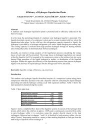
2. Fukano, Takashi, Fitzi, Urs, Löhlein, Karl and Vinage, Isabelle, Efficiency of Hydrogen Liquefaction Plants<br />
(2004)<br />
3. New Energy and Industrial Technology Development Organization, International Clean Energy Network<br />
using Hydrogen Conversion (WE-NET) (1994)<br />
4. Bundesamt für Energiewirtschaft 3003 Bern, Schlussbericht H2 Ortho- Para- Konversion (1993)<br />
5. National Research Council and National Academy of Engineering, The Hydrogen Economy Opportunities,<br />
Costs, Barriers, and R&D Needs (2004)<br />
6. Bossel, Ulf, Eliasson, Baldur and Gordong, Taylor, The Future of the Hydrogen Economy: Bright or Bleak<br />
(2003)<br />
7. Prof. Dr. Quack, Die Schlüsselrolle der <strong>Kryotechnik</strong> in der Wassers<strong>to</strong>ff-Energiewirtschaft (2002)<br />
8. Tzimas, E., Filiou, C., Peteves, S.D., Veyret, J.-B., Hydrogen S<strong>to</strong>rage State of the Art and Future Perspective<br />
(2003)<br />
9. Simbeck, D. and Chang, E., Hydrogen Supply: Cost Estimate for Hydrogen Pathways-Scoping Analysis<br />
(2002)<br />
4