

P37, P52, P55—Release Bracket 20-039 - Airmar Technology ...
P37, P52, P55—Release Bracket 20-039 - Airmar Technology ...
P37, P52, P55—Release Bracket 20-039 - Airmar Technology ...

Create successful ePaper yourself
Turn your PDF publications into a flip-book with our unique Google optimized e-Paper software.
OWNER’S GUIDE &<br />
Transducer or TRIDUCER® Multisensor<br />
Model: <strong>P52</strong><br />
Follow the precautions below for optimal product<br />
performance and to reduce the risk of property<br />
damage, personal injury, and/or death.<br />
WARNING: Always wear safety goggles and a dust<br />
mask when installing<br />
WARNING: When the boat is placed in the water,<br />
immediately check for leaks around the screws and<br />
any other holes drilled in the hull.<br />
CAUTION: This is an impact release bracket only.<br />
Attempting to manually release the bracket may cause<br />
damage.<br />
CAUTION: The bracket protects the sensor from frontal<br />
impact only.<br />
17-003 rev. 06 04/12/11 Transom Mount with Release <strong>Bracket</strong> <strong>20</strong>-<strong>039</strong><br />
CAUTION: Never pull, carry, or hold the sensor by the<br />
cable as this may sever internal connections.<br />
CAUTION: Never strike the sensor.<br />
CAUTION: Never use solvents. Cleaners, fuel, paint,<br />
sealants, and other products may contain strong<br />
solvents, such as acetone, which attack many plastics<br />
greatly reducing their strength.<br />
IMPORTANT: Please read the instructions completely<br />
before proceeding with the installation. These<br />
instructions supersede any other instructions in your<br />
instrument manual if they differ.<br />
Tools & Materials<br />
Safety goggles<br />
Dust mask<br />
Screwdrivers<br />
Wrenches<br />
Scissors<br />
Masking tape<br />
Electric drill<br />
Drill bits and hole saw or spade bit:<br />
<strong>Bracket</strong> holes 4mm, #23, or 9/64"<br />
Fiberglass hull chamfer (preferred), 6mm, or 1/4"<br />
Transom hole (optional) 19mm or 3/4"<br />
<strong>20</strong>mm or 13/16" (Furuno)<br />
Cable clamp holes 3mm or 1/8"<br />
Marine sealant (suitable for below waterline)<br />
Straight edge<br />
Pencil<br />
Zip-ties<br />
Water-based antifouling paint (mandatory in salt water)<br />
Identifying Your Model<br />
The model name is printed on the cable tag.<br />
INSTALLATION INSTRUCTIONS<br />
Applications<br />
• Not recommended for boat with large inboard engine(s).<br />
• Good operation up to 40kn (46MPH).<br />
• Vertically orients the sound beam on hull with deadrise angle up to 22°<br />
• Adjusts to transom angles of up to <strong>20</strong>°<br />
Assembly<br />
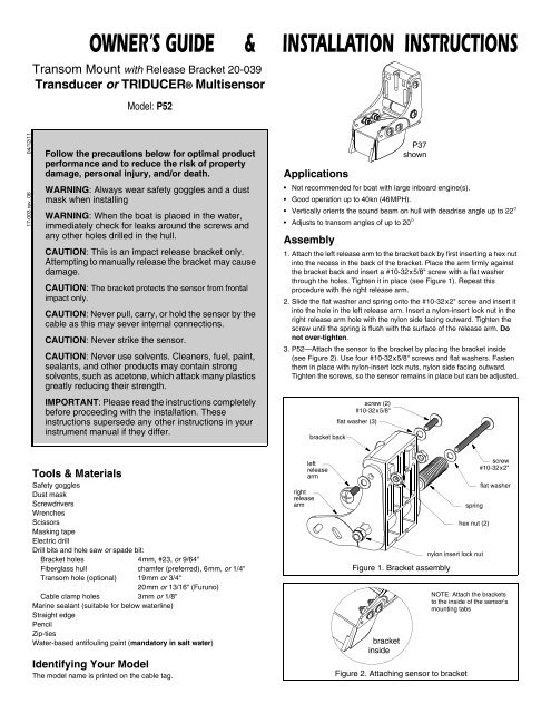
<strong>P37</strong><br />
shown<br />
1. Attach the left release arm to the bracket back by first inserting a hex nut<br />
into the recess in the back of the bracket. Place the arm firmly against<br />
the bracket back and insert a #10-32x5/8" screw with a flat washer<br />
through the holes. Tighten it in place (see Figure 1). Repeat this<br />
procedure with the right release arm.<br />
2. Slide the flat washer and spring onto the #10-32x2" screw and insert it<br />
into the hole in the left release arm. Insert a nylon-insert lock nut in the<br />
right release arm hole with the nylon side facing outward. Tighten the<br />
screw until the spring is flush with the surface of the release arm. Do<br />
not over-tighten.<br />
3. <strong>P52</strong>—Attach the sensor to the bracket by placing the bracket inside<br />
(see Figure 2). Use four #10-32x5/8" screws and flat washers. Fasten<br />
them in place with nylon-insert lock nuts, nylon side facing outward.<br />
Tighten the screws, so the sensor remains in place but can be adjusted.<br />
left<br />
release<br />
arm<br />
right<br />
release<br />
arm<br />
bracket back<br />
screw (2)<br />
#10-32x5/8"<br />
flat washer (3)<br />
Figure 1. <strong>Bracket</strong> assembly<br />
bracket<br />
inside<br />
spring<br />
hex nut (2)<br />
nylon insert lock nut<br />
Figure 2. Attaching sensor to bracket<br />
screw<br />
#10-32x2"<br />
flat washer<br />
NOTE: Attach the brackets<br />
to the inside of the sensor’s<br />
mounting tabs
Mounting Location<br />
CAUTION: Do not mount in an area of turbulence or bubbles:<br />
near water intake or discharge openings; behind strakes, struts,<br />
fittings, or hull irregularities<br />
CAUTION: Avoid mounting the sensor where the boat may be<br />
supported during trailering, launching, hauling, or storage.<br />
• For the best performance, the sensor must be in contact with smooth<br />
water. To identify an area of clean water, observe the water flow off the<br />
transom while the boat is underway.<br />
• Allow headroom space above the bracket for it to release and rotate the<br />
sensor upward (see Figure 3).<br />
• Mount the sensor as close to the centerline (keel) of the boat as<br />
possible to ensure the sensor remains in the water when the boat is<br />
turning.<br />
- Single drive boat—Mount at least 75mm (3") beyond the swing<br />
radius of the propeller (see Figure 4). The starboard side where the<br />
propeller blades are moving downward is preferred.<br />
- Twin drive boat—Mount the sensor between the drives.<br />
2<br />
1–3mm<br />
(1/16–1/8")<br />
transom<br />
height<br />
leading edge<br />
trailing edge<br />
Height without Height with<br />
Model paddlewheel paddlewheel<br />
<strong>P52</strong> 175mm (7-1/2") 215mm (9")<br />
Figure 3. Height required at mounting location and<br />
Sensor angle in “operating position” (<strong>P37</strong> shown)<br />
Align template vertically<br />
Align template arrow<br />
with bottom edge<br />
of transom.<br />
75mm (3") minimum<br />
beyond swing radius<br />
of propeller<br />
Figure 4. Mounting location on single drive boat<br />
Installation<br />
CAUTION: Do not position the leading edge of the sensor lower<br />
than the trailing edge because aeration will occur.<br />
CAUTION: Do not position the sensor deeper into the water than<br />
necessary to avoid increasing drag, spray, and water noise and<br />
reducing boat speed.<br />
CAUTION: To prevent drilling too deeply, wrap masking tape<br />
around the bit 22mm (7/8") from the point.<br />
CAUTION: Fiberglass hull—Minimize surface cracking by<br />
running the drill in reverse until the gelcoat is penetrated.<br />
drill<br />
here<br />
align arrow with<br />
bottom of transom<br />
P55<br />
KEEL (centerline)<br />
<strong>P52</strong><br />
<strong>P37</strong><br />
parallel to waterline<br />
Figure 6. Template<br />
vertical
Hull projection<br />
3mm (1/8")<br />
Figure 6. Hull projection<br />
Mounting & Adjusting<br />
1. Cut-out the template (see Figure 5).<br />
2. At the location selected , position the template so the arrow is aligned<br />
with the bottom edge of the transom. Being sure the template is parallel<br />
to the waterline, tape it in place (see Figure 4).<br />
3. Using a 4mm, #23, or 9/64" bit, drill three holes 22mm (7/8") deep at<br />
the locations indicated.<br />
4. Apply marine sealant to the threads of the #10 x 1-3/4" self-tapping<br />
screws to prevent water seepage into the transom. Slide a flat washer<br />
onto each screw and fasten the bracket assembly to the hull. Do not<br />
tighten the screws completely at this time.<br />
5. Using the vertical adjustment space on the bracket slots, slide the<br />
sensor up or down to provide a projection of 3mm (1/8") (see Figure 6).<br />
6. Adjust the angle of the sensor on the bracket. Using a straight edge,<br />
sight the underside of the sensor relative to the underside of the hull<br />
(see Figure 7). For best results, the trailing edge of the sensor should<br />
be 1-3mm (1/16-1/8") below the leading edge of the sensor or parallel<br />
to the bottom of the hull (see Figure 3). Tighten the screws.<br />
Cable Routing<br />
CAUTION: Do not remove the connector to ease cable routing. If<br />
the cable must be cut and spliced, use <strong>Airmar</strong>’s splash-proof<br />
Junction Box No. 33-035 and follow the instructions provided.<br />
Removing the waterproof connector or cutting the cable, except<br />
when using a water-tight junction box, will void the sensor<br />
warranty.<br />
Route the sensor cable(s) over the transom, through a drain hole, or<br />
through a new hole drilled in the transom above the waterline.<br />
1. If a hole must be drilled through the transom, choose a location well<br />
above the waterline. Check for obstructions such as trim tabs, pumps,<br />
or wiring inside the hull. Mark the location with a pencil. Drill the hole<br />
using the appropriate hole saw or spade bit (to accommodate the<br />
connector).<br />
2. Route the cable(s) over or through the transom.<br />
3. On the outside of the hull secure the cable(s) against the transom using<br />
the cable clamps. Position a cable clamp 50mm (2") above the bracket<br />
and mark the mounting hole with a pencil (see Figure 8).<br />
4. Position the second cable clamp halfway between the first clamp and<br />
the cable hole. Mark this mounting hole. If there are two cables, repeat<br />
this step.<br />
5. If a hole has been drilled through the transom, open the appropriate<br />
slot(s) in the cable cover. The cable cover can accommodate two<br />
cables when there are separate cables for depth and speed/<br />
temperature functions. Position the cover over the cable(s) where it<br />
enters the hull. Mark the two mounting holes.<br />
6. At each of the marked locations, use a 3mm or 1/8" bit to drill a hole<br />
10mm (3/8") deep.<br />
7. Apply marine sealant to the threads of the #6x1/2" self-tapping screws<br />
to prevent water from seeping into the transom. If you have drilled a<br />
hole in the transom, apply marine sealant to the space around the cable<br />
where it passes through the transom.<br />
8. Position the two cable clamps and screw them in place. If used, push<br />
the cable cover over the cable(s) and screw it in place.<br />
9. Route the cable(s) to the instrument(s) being careful not to tear the<br />
cable jacket(s) when passing it through the bulkhead(s) and other parts<br />
of the boat. To reduce electrical interference, separate the sensor<br />
cable(s) from other electrical wiring and sources of noise. Coil any<br />
excess cable and secure it in place with zip-ties to prevent damage.<br />
10.Refer to the echosounder owner’s manual(s) to connect the sensor to<br />
the instrument(s).<br />
Checking for Leaks<br />
When the boat is placed in the water, immediately check for leaks around<br />
the screws and any holes drilled in the hull. Note that very small leaks may<br />
not be readily observed. Do not leave the boat in the water unchecked for<br />
more than three hours.<br />
Antifouling Paint<br />
Aquatic growth can accumulate rapidly on the sensor’s surface reducing<br />
performance within weeks. Surfaces exposed to salt water that do not<br />
interlock, must be coated with antifouling paint. Use water-based antifouling<br />
paint only. Never use ketone based paint, since ketones can attack<br />
many types of plastic possibly causing damage to the transducer. Reapply<br />
paint every 6 months or at the beginning of each boating season.<br />
Operation<br />
slight angle<br />
NO<br />
angle too severe<br />
YES YES<br />
CAUTION: Do not attempt to manually release the bracket. Prying<br />
the release arms may cause fractures resulting in bracket failure.<br />
The bracket releases immediately upon impact. To reset, push down on<br />
the release arms until they snap into place. The arms are then locked in<br />
the operating position.<br />
cable cover<br />
parallel<br />
cable clamp<br />
Figure 8. Cable routing<br />
50mm (2")<br />
NO<br />
angle in wrong direction<br />
Figure 7. Sensor angle adjustment (<strong>P37</strong> shown)<br />
3
Setting the <strong>Bracket</strong> Release Point<br />
CAUTION: Never compress the top of the spring below the tab,<br />
because the bracket will be locked in place and will not release.<br />
When the spring is even with the tab, the release force is<br />
maximum at about 100lb. (450N).<br />
CAUTION: Do not set the bracket to withstand more force than<br />
the minimum required to hold the sensor in the "down" (operating)<br />
position, since this increases the chance that the bracket will not<br />
release when the sensor is struck.<br />
There is considerable force on the bracket during normal operation. The<br />
amount of force is proportional to the drag which is created by the:<br />
• Sensor—shape, size, weight, and amount of projection below the<br />
transom.<br />
• Speed—the square of the speed of the boat.<br />
A larger and heavier sensor creates more drag as does a higher boat<br />
speed. For example, the drag at 40kn (46MPH) is four times that at <strong>20</strong>kn<br />
(23MPH). The correct bracket release setting has been found when the<br />
sensor remains in the “down” (operating) position under normal operating<br />
conditions.<br />
The factory setting is 40lb. (180N). The adjustment screw may need<br />
tightening if the top speed of the boat is more than 30kn (34MPH).<br />
Gradually increase the boat speed and observe the echosounder. When<br />
the bracket releases, there will be an instantaneous loss of echo. If the<br />
bracket releases before reaching top boat speed, reset the bracket in the<br />
“down” (operating) position and turn the adjustment screw clockwise one<br />
or two full turns (see Figure 9). Repeat the test until the desired result is<br />
obtained.<br />
NOTE: One turn equals 10lb. (45N).<br />
Testing on the Water<br />
1. Become familiar with your echosounder’s performance at a speed of 4kn<br />
(5MPH).<br />
2. Gradually increase the boat speed and observe the gradual decline in<br />
performance due to turbulent water flowing over the transducer’s active<br />
surface.<br />
3. If the decline in performance is sudden (not gradual), identify the boat<br />
speed at which the onset occurred. Return the boat to this speed, then<br />
gradually increase speed while making moderate turns in both directions.<br />
4. If the performance improves while turning to the side on which the<br />
sensor is installed, the transducer’s position probably needs<br />
adjustment. It is probably in aerated water.<br />
4<br />
spring<br />
adjustment<br />
screw<br />
Figure 9. <strong>Bracket</strong><br />
release adjustment<br />
To improve performance, try the following one at a time in the order<br />
given.<br />
a. Increase the sensor’s angle in the water.<br />
b. Move the sensor deeper into the water in increments of 3mm (1/8").<br />
c. Move the sensor closer to the centerline of the boat.<br />
Fill unused screw holes with marine sealant.<br />
AIRMAR ®<br />
TECHNOLOGY CORPORATION<br />
tab<br />
Do not compress<br />
top of spring<br />
beyond tab<br />
NOTE: High-speed operation [above 35kn (40MPH)] may require less<br />
projection in the water to improve performance and reduce the chance<br />
that water pressure will cause the bracket to release.<br />
Maintenance, Repair, & Replacement<br />
Speed Sensor<br />
Remove the paddlewheel assembly before beaching, trailering, or hauling<br />
the boat, since these are the main causes of speed sensor breakage.<br />
Cleaning<br />
Figure 10. 33-105<br />
shear<br />
pins (4)<br />
Clean the transducer’s surface with a Scotch-Brite® scour pad and mild<br />
household detergent taking care to avoid making scratches. If the fouling<br />
is severe, lightly wet sand with fine grade wet/dry paper.<br />
If the paddlewheel becomes fouled or inoperable, unsnap the paddlewheel<br />
assembly from the main housing for cleaning. Severe cases may require<br />
removal of the paddlewheel. Using a small screwdriver, remove the<br />
paddlewheel shaft retainers. (If a retainer is lost, a dab of RTV caulk on the<br />
end of the shaft will secure it.) If necessary, use a stiff brush or putty knife to<br />
remove the growth being careful to avoid scratching the transducer’s face.<br />
Wet sanding is permissible with fine grade wet/dry paper.<br />
Sensor Replacement & Parts<br />
Copyright © <strong>20</strong>00 <strong>20</strong>11 <strong>Airmar</strong> <strong>Technology</strong> Corp. All rights reserved.<br />
shear pins (4)<br />
Figure 11. 33-110<br />
The information needed to order a replacement sensor is printed on the<br />
cable tag. Do not remove this tag. When ordering, specify the part<br />
number, date, and frequency in kHz.<br />
Replace broken or worn parts immediately. The speed sensor shear pins<br />
are designed to fracture upon impact. The water-lubricated paddlewheel<br />
bearings have a life of up to 5 years on low-speed boats [less than 10kn<br />
(11MPH)] and 2 years on high-speed vessels. Some depth/temperature<br />
units can be upgraded by adding a speed sensor.<br />
For a replacement paddlewheel carrier without a cable, order the Snap-In<br />
Paddlewheel Carrier 33-105 (see Figure 11); for an assembly with a<br />
cable, order Transom Paddlewheel Kit 33-110 (see Figure 12) from your<br />
marine dealer or echosounder manufacturer.<br />
<strong>Airmar</strong> offers a stainless steel Kick-Up <strong>Bracket</strong> <strong>20</strong>-035-2 which rotates the<br />
sensor up when excessive force is applied. This bracket allows the user to<br />
manually release the sensor to protect it when trailering, beaching, or<br />
hauling the boat. Both brackets use the same mounting holes.<br />
Obtain parts from your instrument manufacturer or marine dealer.<br />
Gemeco Tel: 803-693-0777<br />
(USA) Fax: 803-693-0477<br />
email: sales@gemeco.com<br />
<strong>Airmar</strong> EMEA Tel: +33.(0)2.23.52.06.48<br />
(Europe, Middle East, Africa) Fax: +33.(0)2.23.52.06.49<br />
email: sales@airmar-emea.com<br />
35 Meadowbrook Drive, Milford, New Hampshire 03055-4613, USA<br />
www.airmar.com


