Quick Guide to - Festo
Quick Guide to - Festo
Quick Guide to - Festo

You also want an ePaper? Increase the reach of your titles
YUMPU automatically turns print PDFs into web optimized ePapers that Google loves.
<strong>Quick</strong> <strong>Guide</strong> <strong>to</strong><br />
CPX-FB11 DeviceNet connected <strong>to</strong><br />
Rockwell Au<strong>to</strong>mation PLC:<br />
ControlLogix, SLC500, CompactLogix<br />
1 2<br />
Station<br />
address<br />
0 … 63<br />
binary coded<br />
3<br />
125 kBd<br />
250 kBd<br />
500 kBd<br />
Start-up hardware settings Using RSNetWorx for DeviceNet<br />
Operating mode:<br />
Remote Standard<br />
I/O EDS<br />
Setting up the network<br />
configuration<br />
1. A DeviceNet Scanner must exist in the network<br />
e.g. 1756-DN ControlLogix, 1747-SDN SLC<br />
The DeviceNet scanner is mapping the network <strong>to</strong> the PLC register<br />
2. Editing the Scan list<br />
DeviceNet Scanner -><br />
"Properties" -> Scan list<br />
Add your device from the<br />
“Available Devices” list <strong>to</strong> the<br />
“Scanlist”<br />
3. Setting up I/O Parameters<br />
Scan list -> Device-> "Edit I/O Parameters…"<br />
! A manual setup of input/output data size is necessary<br />
(Polled, CoS or Cyclic)<br />
Additional<br />
Diagnostic<br />
Bits:<br />
- deactivated<br />
Optional: Adding up 1 byte diagnostic data <strong>to</strong> the “Strobed” connection<br />
Fes<strong>to</strong> AG & Co KG <strong>Quick</strong> <strong>Guide</strong> <strong>to</strong> CPX-FB11/Rockwell Au<strong>to</strong>mation PLC Version A3<br />
4<br />
General information / preparation<br />
Setting up the network configuration and parameters via<br />
RSNetWorx for DeviceNet<br />
EDS available at www.fes<strong>to</strong>.com/fieldbus<br />
Standard EDS with just digital modules: dnio1cpx<br />
Standard EDS including analogue modules: dnio2cpx<br />
Optional: Modular EDS for use in RSNetworx<br />
Documentations with detailed descriptions<br />
available at www.fes<strong>to</strong>.com (Au<strong>to</strong>mation -> Documentation)<br />
Search for:<br />
CPX-FB11 (DeviceNet manual): EN - 526422<br />
CPX-SYS (CPX system manual): EN - 526446<br />
1. Setting up the I/O connection <strong>to</strong> the DeviceNet scanner<br />
2. Changing CPX parameters<br />
3. Data-access in the network online modus<br />
Usually the network consists of the DeviceNet scanner and the field<br />
devices. Each device has its own address. The DeviceNet slaves have <strong>to</strong> be<br />
mapped <strong>to</strong> the scanlist of the scanner.<br />
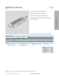
Using LED’s for the<br />
identification of device status<br />
Device network status<br />
Module status Device status normal<br />
Device not ready<br />
Device has connection <strong>to</strong> PLC<br />
Network status Network ok, but no connection<br />
Address problem or bus off<br />
I/O status Device controlled by PLC<br />
Device in IDLE state<br />
CPX hardware status<br />
System failure OK<br />
Information<br />
Diagnostic<br />
Hardware defect<br />
Power system / load Power OK<br />
Outside <strong>to</strong>lerance<br />
OK<br />
Modify status Saved parameters<br />
Force active
Tip Tip<br />
Input data order<br />
“polled, COS or cyclic”<br />
I/O Diagnostic Bits<br />
(Deactivated by default)<br />
Analogue modules,<br />
each channel 16 Bit<br />
Technologies modules<br />
(e.g. CPI Interface, CPX-FEC)<br />
Digital and valve modules<br />
(I/O, MPA, Pneu. Interface)<br />
Input data “Strobed”<br />
1 Byte Status (optional)<br />
Tip<br />
CPX-FB11 I/O mapping Using the “Status Bits” of the<br />
“Strobed Connection”<br />
1<br />
2<br />
3<br />
4<br />
Output data order<br />
“polled, COS or cyclic”<br />
ADR – Au<strong>to</strong> Address<br />
Recovery<br />
IDLE and Fault Mode<br />
I/O Diagnostic Bits<br />
(Deactivated by default)<br />
Analogue modules,<br />
each channel 16 Bit<br />
Technologies modules<br />
(e.g. CPI Interface, CPX-FEC)<br />
Digital and valve modules<br />
(I/O, MPA, Pneu. Interface)<br />
By using the ADR function field device parameters are directly s<strong>to</strong>red<br />
inside the PLC DeviceNet scanner. The scanner must support this function.<br />
An au<strong>to</strong>matic recovery of<br />
parameters during a device<br />
exchange is possible<br />
Activating ADR:<br />
Go <strong>to</strong> scanner<br />
Properties -> ADR<br />
1. “Enable ADR”<br />
2. “Load Device Config”<br />
3. “Configuration<br />
Recovery”<br />
Tip<br />
Tip Tip<br />
IDLE mode:<br />
Defines the status of output<br />
signals during the connection<br />
<strong>to</strong> a PLC which is<br />
actually s<strong>to</strong>pped or in<br />
programming mode<br />
FAULT mode:<br />
Defines the status of output<br />
signals during a network failure<br />
when connected <strong>to</strong> a running PLC<br />
The default setup defines all<br />
output signals <strong>to</strong> the OFF<br />
state during one of the modes<br />
An optional channel based setup<br />
can be made:<br />
Value <strong>to</strong> OFF (default)<br />
Value <strong>to</strong> ON<br />
Hold Last State<br />
! The internal CPX mapping<br />
cannot be changed by the<br />
configuration <strong>to</strong>ols.<br />
PROG<br />
PROG<br />
PROG<br />
RUN<br />
RUN<br />
RUN<br />
The “Status Bits” are 8 major signals which can be considered inside the<br />
PLC program. They are accessed via the optional “Strobed connection”<br />
Bit Diagnostic information Description<br />
----------------------------------------------------------------------------------------------<br />
0 Fault at valve Module type on which<br />
1 Fault at output a fault has occurred<br />
2 Fault at input<br />
3 Fault on analogue/function module<br />
----------------------------------------------------------------------------------------------<br />
4 Under voltage Type of fault<br />
5 Short circuit/overload<br />
6 Wire fracture/open load<br />
7 Other faults<br />
----------------------------------------------------------------------------------------------<br />
Additional and advanced diagnostics can be read out with:<br />
- Online mode of RSNetWorx<br />
- Handheld unit CPX-MMI<br />
Modular EDS makes an easier parameterisation possible. Just existing<br />
parameters are visible. Parameters of complex modules and technology<br />
modules are just listed in modular EDS. The I/O size is visible.<br />
1. Install all EDS files from<br />
the CPX modular EDS file<br />
library<br />
2. Change the DIP switches<br />
Operating mode:<br />
Remote I/O<br />
Modular EDS<br />
Attention:<br />
- In combination with<br />
RSNetWorx v.5 only<br />
- The internal I/O mapping is<br />
still the standard mapping<br />
(see Step 4)<br />
Modular EDS for CPX-FB11<br />
(from R14, SW 25.04.05)<br />
Additional diagnostics<br />
and system data access<br />
1. Explicit Messaging via DeviceNet<br />
A library with objects for data access via DeviceNet is available.<br />
The library includes objects (data groups), instances (module no)<br />
and attributes (parameters) for almost all system data.<br />
More details: Manual CPX-FB11 Attachments<br />
2. Activating Status Interface or diagnostic Bits in<strong>to</strong> the process data<br />
Diagnostic Bits: Instead of using the status bits via<br />
“Strobed connection”, an alternative mapping in<strong>to</strong><br />
the process data is possible (2 Byte IN)<br />
Status Interface: Allows an access <strong>to</strong> advanced CPX<br />
data via a 2 Byte IN/OUT interface inside<br />
the process data.<br />
3. Using alternative <strong>to</strong>ols<br />
- RSNetWorx in online mode<br />
- CPX-MMI - Handheld-<strong>to</strong>ol which is optimised for use of CPX-Terminals<br />
Fes<strong>to</strong> AG & Co KG <strong>Quick</strong> <strong>Guide</strong> <strong>to</strong> CPX-FB11/Rockwell Au<strong>to</strong>mation PLC Version A3