Drakensberg Pumped Storage Scheme - Eskom
Drakensberg Pumped Storage Scheme - Eskom
Drakensberg Pumped Storage Scheme - Eskom
You also want an ePaper? Increase the reach of your titles
YUMPU automatically turns print PDFs into web optimized ePapers that Google loves.
<strong>Eskom</strong> Holdings Limited Reg No 2002/015527/06<br />
<strong>Drakensberg</strong><br />
PUMPED STORAGE SCHEME
<strong>Eskom</strong> is at the forefront of power generation technology<br />
Vast and imaginative schemes have assured <strong>Eskom</strong>’s prominence in the<br />
energy world and attracted international attention from related sectors.<br />
Technical information is the key to a professional understanding of this<br />
multi-disciplinary engineering project.<br />
Revised October 2005<br />
<strong>Drakensberg</strong> Power Station<br />
Private Bag X302 Jagersrust 3354 South Africa<br />
Tel +27 36 438 6250 Fax +27 36 438 6073<br />
www.eskom.co.za<br />
<strong>Drakensberg</strong> Visitors Centre<br />
Tel +27 36 438 6046 Fax +27 36 438 6015
A BARRIER OVERCOME<br />
Introduction<br />
On one side of the watershed the Tugela River carries its waters almost<br />
unused to the Indian Ocean. On the other, the Vaal River flows towards<br />
the Atlantic, its potential exploited to the utmost. In the early 1970s demands<br />
made on the Vaal were growing relentlessly and problems of future water<br />
supply for industry, commerce and domestic use in the Gauteng area were<br />
becoming increasingly serious. The solution was obvious – transfer water from<br />
the catchment area of the Tugela to that of the Vaal.<br />
As water transfer over the <strong>Drakensberg</strong> would require the construction of<br />
reservoirs, channels and pumps, it opened the way to build a hydroelectric power<br />
station which could further exploit the potential of water resources being made<br />
available. The Department of Water Affairs and Forestry (DWAF) and <strong>Eskom</strong><br />
started work on this dual-purpose scheme in 1974. In 1982 the project was<br />
completed, operating as a pumped storage scheme and as a pumping station for<br />
water transfer over the <strong>Drakensberg</strong> from the Tugela to the Vaal.<br />
Almost the whole complex was constructed underground and the surface buildings<br />
and access roads were built in such a way that they can hardly be seen as a result<br />
the beautiful natural surroundings appear virtually untouched.
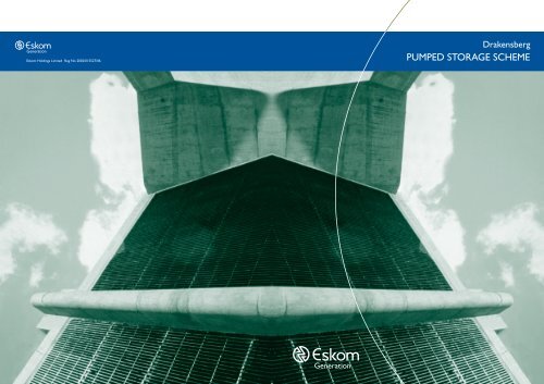
THE 6 m HEADRACE INLETS, SITUATED IN<br />
THE DRIEKLOOF DAM, HOUSE<br />
THE EMERGENCY / MAINTENANCE GATES<br />
<strong>Pumped</strong> storage schemes<br />
The pumped storage scheme is a variation of the more common<br />
run-of-river hydroelectric power stations. The power station of the pumped<br />
storage scheme is built on a waterway that links an upper and lower reservoir.<br />
Electricity is generated only during peak demand periods or emergencies<br />
by channelling water from the upper to the lower reservoir through<br />
reversible pump-turbine sets. During periods of low energy demand this<br />
same water is pumped back from the lower to the upper storage reservoir<br />
by the reversible sets.<br />
The <strong>Drakensberg</strong> scheme paved the way for <strong>Eskom</strong>’s second pumped storage project<br />
at Palmiet in the Cape. These power stations have the advantage of being able to<br />
generate electricity within three minutes, whereas coal-fired stations require a<br />
minimum of 8 hours from cold startup to start generating power.<br />
By pumping water from the lower to the upper reservoirs during low-peak periods,<br />
both the Palmiet and <strong>Drakensberg</strong> schemes help to flatten the load demand curve<br />
of the national system by using the excess generating capacity available in these<br />
off-peak periods.<br />
Tugela-Vaal water transfer scheme<br />
South Africa’s major industrial and mining activities<br />
are centred in the Gauteng area, which is<br />
dependent on the Vaal River for its water supplies.<br />
The Vaal’s capacity of 1 545 million m 3 a year was<br />
sufficient to meet demands until 1974. By<br />
transferring water from the Tugela River over the<br />
<strong>Drakensberg</strong> escarpment and into the Wilge River,<br />
a tributary of the Vaal, the DWAF calculated it<br />
could increase the Vaal’s capacity to meet demands<br />
until 1992.<br />
Studies showed that the best advantage would<br />
be derived from storing the water in a deep<br />
reservoir with limited surface area to minimise<br />
evaporative losses. This would permit the level of the extensive and wasteful<br />
Vaal Dam to be reduced to previously unacceptable levels. In times of need,<br />
water from the reservoir could then be released into the Vaal Dam.<br />
The scheme provides for the annual transfer of 631 million m 3 of water<br />
and an annual storage capacity of 2 660 million m 3 , which increases<br />
the Vaal’s yield to 2 345 million m 3 – 52% more than the natural yield.<br />
The Driel Barrage is situated just below the confluence of the<br />
Mlambonja and the Tugela Rivers.<br />
02 <strong>Drakensberg</strong><br />
ESKOM PUMPED STORAGE SCHEME<br />
Operating data<br />
Generation energy equivalent 27,6 GWh<br />
to 27,0 million m3 Time required to pump 39 hours<br />
27,0 million m3 of water from<br />
lower to upper reservoir<br />
Type of operational cycle Weekly<br />
Cycle efficiency 73,7%<br />
Electrical aspects<br />
Rated voltage 420 kV<br />
Rated frequency 50 Hz<br />
Lightning surge voltage 1 425 kV<br />
Switching surge voltage 1 050 kV<br />
AC voltage 50 Hz/min 630 kV<br />
Rated current 2 500 A<br />
Short-circuit current:<br />
Symmetrical 31,5 kA<br />
Asymmetrical 38,6 kA<br />
Single phase to earth fault 36,2 kA<br />
Making current, peak value 92,4 kA<br />
Construction / commissioning history<br />
Construction commenced December 1974<br />
Commissioning<br />
First set May 1981<br />
Final set May 1982<br />
Major dams in the Tugela-Vaal <strong>Scheme</strong>:<br />
Woodstock Dam<br />
Full supply level 1 175,56 masl<br />
Type of dam Earth fill<br />
Height above lowest foundation 51,0 m<br />
Length of crest 760,0 m<br />
Volume content of dam wall 2,0 million m3 Gross capacity of reservoir 381,0 million m3 Maximum discharge of spillway 2 x 500 m3 /s<br />
Type of spillway 1 controlled tunnel<br />
1 uncontrolled chute<br />
Sterkfontein Dam<br />
Full supply level 1 702 masl<br />
Type of dam Earth fill<br />
Height above lowest foundation 93,0 m<br />
Length of crest 3 060 m<br />
Volume content of dam wall 17,0 million m3 Gross capacity of reservoir 2 656,0 million m3 Surface area when full 6 937,0 ha<br />
Catchment area 191 km2 Maximum discharge of spillway 2 x 500 m3 /s<br />
Spillway None<br />
Capacity of outlet works 220 m3 /s<br />
Major Contractors<br />
Civil engineering<br />
Exploratory excavation Roberts Union Corporation<br />
Preliminary civil work Batignolle, Cogefar & African Batignolle<br />
Main civil work Drakon (LTA & Shaft Sinkers)<br />
Supply of aggregate Hippo Quarries Ltd<br />
Headrace civil work Spie Batignolle<br />
Surface building SM Goldstein<br />
Structural steelwork Genrec Steel<br />
Kilburn and Driekloof Dams Department of Water Affairs<br />
Civil engineering consultants Gibb, Hawkins & Partners<br />
Mechanical engineering<br />
Pump-turbines, governors and Mitsui representing Toshiba,<br />
spherical valves Voest- Alpine and Hitachi<br />
Penstocks Sorefame, Broderick<br />
Gates and screens Neyrpic-BVS Technics<br />
Power station cranes Krupp SA (Pty) Ltd<br />
Pipework Mather & Platt<br />
Electrical-engineering<br />
Generator-motors Brown Boveri<br />
Cabling Industrial Electrical Co<br />
Transformers ASEA Electric Co Ltd<br />
SF6 metal-clad switchgear Brown Boveri<br />
Control room equipment Siemens<br />
10 <strong>Drakensberg</strong> ESKOM PUMPED STORAGE SCHEME
TECHNICAL DATA<br />
The reservoirs<br />
Upper reservoir: Driekloof<br />
Full supply level 1 700 masl<br />
Minimum level 1 680 masl<br />
Active storage capacity 27,5 million m3 Minimum storage volume 8,15 million m3 Type of dam Rock fill<br />
Height above lowest foundation 46,6 m<br />
Length of crest 500 m<br />
Volume content of dam wall 843 000 m3 Gross capacity of reservoir 35,6 million m3 Capacity of spillway into 220 m3 Sterkfontein reservoir<br />
/s<br />
Type of spillway Baffled apron on embankment<br />
Non-overflow crest 1 702,44 masl<br />
Spillway crest 1 700,0 masl<br />
Maximum operating water level 1 702,0 masl<br />
Minimum operating water level:<br />
Normal 1 684,8 masl<br />
Emergency 1 680,0 masl<br />
Lower reservoir: Kilburn<br />
Full supply level<br />
Minimum level for<br />
1 256,0 masl<br />
4 machines operating 1 235,0 masl<br />
Active storage capacity 27 million m3 Minimum storage volume 6,6 million m3 Type of dam Earth fill<br />
Height above lowest foundation 51,0 m<br />
Length of crest 825,0 m<br />
Volume content of dam wall 2,9 million m3 Gross capacity of reservoir 36,0 million m3 Capacity of spillway 320 m3 /s<br />
Type of spillway Side channel with chute<br />
Non-overflow crest 1 259,0 masl<br />
Spillway crest 1 256,0 masl<br />
Lowest operational level for<br />
4 machines generating<br />
1 235,0 masl<br />
Headrace tunnels:<br />
Number 2<br />
Internal equivalent diameter 6,0 m<br />
Length 1 502,1 m & 1 497,1 m<br />
Type of construction Concrete-lined<br />
Maximum flow velocity 5,4 m/s<br />
Headrace surge shafts:<br />
Number 2<br />
Internal diameter 14 m<br />
Height 89 m<br />
Type of construction Cylindrical<br />
Pressure shafts and tunnels (penstocks)<br />
Number 2, each bifurcating to 2 machines<br />
Length (up to spiral inlet) 1 614,3 m & 1 611,3 m<br />
Type of construction Concrete-lined except last 522,6 m<br />
& 494,3 m which are steel-lined<br />
in each case<br />
Maximum flow velocities 6,4 m/s for concrete-lined sections, and<br />
8,4 m/s increasing to 19 m/s at machines<br />
for steel-lined sections<br />
Underground power station:<br />
Number of machines 4<br />
Continuous rating of each 250 MW at 0,9 power factor<br />
machine for generation<br />
Maximum power for pumping 270 MW<br />
per machine<br />
Range of net head for generation<br />
using 4 machines<br />
400,0 m to 448,5 m<br />
Range of pumping head<br />
using 4 machines<br />
436,4 m to 476,0 m<br />
Maximum permissible pressure<br />
in the penstocks<br />
7,22 MPa<br />
Type of pump-turbine Single-stage, reversible Francis<br />
Rated speed for both directions<br />
of rotation<br />
375 r/min<br />
Method of pump starting Pony motor rated at 16,5 MW<br />
Type of operation Automatic<br />
Type of control Local and remote<br />
Tailrace surge chambers:<br />
Number 2<br />
Internal diameter 16,0 m<br />
Height 81,6<br />
Type of construction Cylindrical<br />
Tailrace tunnel:<br />
Number 1<br />
Internal equivalent diameter 8,5 m<br />
Length 1 402 m<br />
Type of construction Concrete-lined<br />
Maximum flow velocity 5,4 m/s<br />
09 <strong>Drakensberg</strong> ESKOM PUMPED STORAGE SCHEME<br />
Water is pumped at an average continuous rate of 20 m 3 /s from<br />
the Driel Barrage into a canal which leads to the Jagersrust forebay.<br />
From here it is pumped into the Kilburn reservoir, which is the<br />
lower reservoir in the <strong>Drakensberg</strong> <strong>Pumped</strong> <strong>Storage</strong> <strong>Scheme</strong>. The<br />
upper reservoir, Driekloof Dam, is situated in a branch of the<br />
Sterkfontein reservoir into which it overflows when full. The<br />
DWAF raised the wall of the Sterkfontein Dam to 93 m to increase<br />
its capacity to the desired 2 660 million m 3 .<br />
When the DWAF received its first water from the Lesotho<br />
Highlands Project in February 1998, it was decided to shut<br />
down the Tugela-Vaal (TUVA) canal for a period of 2 years,<br />
commencing in June 1998, to upgrade the canal. The following<br />
works were undertaken:<br />
- Relining of the canal with concrete, using the old lining<br />
as a base.<br />
- Installation of an improved drainage system.<br />
- Provision for the expansion of concrete slabs to prevent<br />
cracking, which was a major problem.<br />
This also gave DWAF the opportunity to upgrade the installations<br />
of the electrical switchgear and pump instrumentation and to<br />
overhaul pumps and valves.<br />
Construction of the power station caverns<br />
Environmental considerations as well as engineering requirements<br />
led to the decision to build the power station underground.<br />
Certain aspects of environmental conservation introduced during<br />
the construction of the <strong>Drakensberg</strong> <strong>Pumped</strong> <strong>Storage</strong> <strong>Scheme</strong><br />
had a profound influence on <strong>Eskom</strong>’s approach to the later Palmiet<br />
project. The scheme at <strong>Drakensberg</strong> witnessed the beginning of<br />
the integration of both environmental and technical principles,<br />
which was to be a hallmark of the Palmiet undertaking. Contractors<br />
and <strong>Eskom</strong>’s engineers came to recognise the importance of the<br />
environmental protection and restoration and co-operated willingly<br />
in <strong>Eskom</strong>’s endeavours to safeguard the natural surroundings. The<br />
rock in which the power station was built consists of relatively<br />
weak mudstone, siltstone and sandstone, which are horizontally<br />
bedded. Both primary and secondary rock reinforcement was<br />
used with fast-resin anchorages of 6 m and 3 m in length, respectively.<br />
To reduce the maximum cavern span for the power station<br />
complex, separate halls were constructed for the valves, the pumpturbines<br />
and the transformers.<br />
The construction of the halls was undertaken in stages, working<br />
downward from the central crown and inserting rockbolts<br />
according to a carefully designed pattern. The cavern walls were<br />
lined with shotcrete soon after excavation to prevent rock<br />
deterioration. When rock movement became minimal, a second<br />
lining of shotcrete was applied with weldmesh reinforcement.<br />
The same techniques were applied to tunnelling. During construction<br />
of the underground power station complex, 1 330 000 t or<br />
510 000 m 3 of rock were excavated, and 220 000 m 3 of concrete<br />
and 45 000 m 3 of pneumatically applied concrete were placed.<br />
Some 6 000 t of reinforcing steel were used in the concrete, and<br />
the 75 000 rock bolts inserted amounted to 260 km of steel rods.<br />
The reservoirs<br />
Four major storage reservoirs were constructed within the<br />
Tugela-Vaal water transfer scheme: Woodstock, Kilburn, Driekloof<br />
and Sterkfontein.<br />
Woodstock<br />
The Woodstock Dam regulates the flow of the Tugela River upstream<br />
of its confluence with the Mlambonja River before it enters<br />
Driel Barrage. The foundations of the embankment are built of<br />
sandstone, siltstone and mudstone. The zoned embankment itself<br />
is constructed from silt and sand alluvial deposits and weathered<br />
materials from the basin of the reservoir. The upstream slope is<br />
protected by dumped rip-rap, whereas the downstream slope has<br />
been grassed to combat erosion.<br />
A tunnel with a capacity of 418 m 3 /s carries normal discharge into<br />
a stilling basin, while a spillway chute caters for flood discharges<br />
estimated at 1 000 m 3 /s. The chute includes a curved ogee spillway<br />
section, a transition zone with the floor elevated along the centre<br />
line and an 11 m wide chute. A flip-bucket energy disperser at<br />
the end of the chute diverts the direction of the outflow towards<br />
the direction of the river flow. An auxiliary spillway is designed<br />
to cater for maximum floods of up to 2 730 m 3 /s.<br />
Kilburn<br />
Kilburn Dam, in the foothills of the escarpment, is the lower<br />
reservoir of the <strong>Pumped</strong> <strong>Storage</strong> <strong>Scheme</strong>. Since the water level<br />
fluctuates over a depth of 21 m as the scheme operates, the<br />
upstream face of the dam has a flattish slope to improve its stability<br />
and is protected by rip-rap (dolerite). The downstream face is<br />
grassed. This not only combats erosion but blends in with the<br />
surrounding countryside.<br />
03 <strong>Drakensberg</strong> ESKOM PUMPED STORAGE SCHEME
CROSS SECTION OF A UNIT<br />
The maximum emergency discharge from the power station in the<br />
direction of rotation is 312 m 3 /s, which is more than the estimated<br />
maximum flood discharge from the catchment area. The side-chute<br />
spillway is designed to cope with the flow rate during emergency<br />
generation. It has an energy-dispersing device downstream in the form<br />
of a hydraulic-jump stilling basin that includes baffle blocks. The<br />
embankment includes a baffled inlet chute for the continuous transfer<br />
of water at 11 m 3 /s from the Jagersrust forebay. The inlet was modified<br />
to increase this figure to approximately 20 m 3 /s.<br />
Driekloof<br />
Driekloof Dam, located in a branch of the Sterkfontein reservoir, is<br />
the upper reservoir of the <strong>Pumped</strong> <strong>Storage</strong> <strong>Scheme</strong>. It is partly submerged<br />
when Sterkfontein is full. During the weekly cycle of the scheme, the<br />
water level fluctuates over 22 m. The rockfill construction includes<br />
mud-stone, dolerite, sandstone and a central clay core.<br />
The commonest rock type underlying the site is a red-brown mudstone<br />
that slakes rapidly and can be hand moulded when saturated. A spillway<br />
was constructed to channel water into the Sterkfontein reservoir. It<br />
consists of a baffled apron placed centrally over both sides of the dam.<br />
Spillway discharge capacity from the Driekloof reservoir to Sterkfontein<br />
is approximately 220 m 3 /s. When the Sterkfontein reservoir is full and<br />
electricity generation causes the water level in the Driekloof reservoir<br />
to drop below the spillway crest, the maximum discharge from the Sterkfontein into<br />
the Driekloof reservoir is 320 m 3 /s.<br />
Sterkfontein<br />
Sterkfontein Dam is situated some kilometres from the edge of the <strong>Drakensberg</strong><br />
escarpment. The volume of the dam wall makes it the largest earth-fill embankment<br />
dam in South Africa. It has an earth-fill embankment with an impervious core that<br />
slopes upstream. Most of the fill consists of weathered mudstone, shale and dolerite,<br />
all locally obtained. The catchment area of the reservoir is too small to require<br />
a spillway.<br />
Mechanical aspects<br />
The four reversible Francis sets are designed to generate a rated output<br />
of 250 MW each at 375 r/min and to pump against a maximum head of<br />
476,7 m. These parameters qualify the machines as among the most powerful<br />
single-stage pumped storage stations in the world as seen from the<br />
following comparative figures:<br />
Power station Turbine Pump Speed<br />
output head r/min<br />
MW (max) m (max)<br />
Racoon (USA) 400 323 300<br />
Imaichi (Japan) 360 573 429<br />
04 <strong>Drakensberg</strong> ESKOM PUMPED STORAGE SCHEME<br />
Ludlington (USA) 343 114 112,5<br />
Ohkawachi (Japan) 329 428,3 360<br />
Dinorwig (Wales) 317 545 500<br />
Bajina Bassa (Yugoslavia) 315 621,3 428,6<br />
Okutatagari (Japan) 310 424 300<br />
Tenzan (Japan) 300 548,8 400<br />
Mingtan (Taiwan) 275 410,8 400<br />
<strong>Drakensberg</strong> (South Africa) 270 473,5 375<br />
Okukiyotsu (Japan) 260 512 375<br />
Minghu (Taiwan) 257 326 300<br />
Ohira (Japan) 256 545 400<br />
Numappara (Japan) 230 528 375<br />
Montezic (Western Europe) 228 426,6 429<br />
Chaira (Bulgaria) 216 701 600<br />
Okuyoshino (Japan) 207 539 514<br />
Palmiet (SouthAfrica) 204 305,8 300<br />
Cavitation posed a challenge since cavitation erosion increases<br />
exponentially with relative flow velocity. In the case of the<br />
<strong>Drakensberg</strong> machines, this velocity reaches nearly 20 m/s.<br />
Submergence of 65 m to 86 m below the level of the Kilburn<br />
reservoir guarantees that no unacceptable cavitation damage<br />
occurs, even when pumping against a maximum head. An interesting<br />
aspect of the machines is that they are controlled by electronic<br />
governors of the electrohydraulic type with proportional-integralderivative<br />
characteristics. The control output is at the frequency<br />
of the generated power.<br />
Each machine can be isolated from the water in the penstocks by<br />
its own spherical shut-off valve. These valves are 2,25 m in diameter<br />
and are operated by hydraulic servomotors. They can be closed<br />
during operational conditions, even when water hammer is taking<br />
place. A special upstream seal is provided for maintenance purposes.<br />
Electrical aspects<br />
The generator-motors of the pump-turbines can run unloaded<br />
as synchronous condensers in the direction of generation rotation<br />
to provide reactive compensation. In this case, the spherical valves<br />
are shut and compressed air is used to depress the water in the<br />
draft tubes to below the level of the runner, thus minimising the<br />
torque. The excitation is then adjusted to give the required reactive<br />
compen-sation. The synchronous condenser mode of operation<br />
can be considered as a spinning reserve as it allows the machine<br />
to be loaded as a generator by releasing the compressed air from<br />
the turbine chamber and opening the spherical valve and guide<br />
vanes.<br />
Unlike normal hydroelectric generators, the generator motors<br />
run in both directions in a regular cycle. The severe fatigue stresses<br />
influenced the design of the stator core and windings.<br />
The generation voltage of 11 kV is transformed to the national<br />
grid voltage of 400 kV. For several reasons, including security,<br />
proximity to the generators, reduction of busbar lengths and<br />
environmental considerations, the transformers and switchgear<br />
are located underground up to 86 m below the lower reservoir<br />
level. Consequently, a special cooling system is necessary. Each<br />
transformer is fitted with two oil / water and two water / water<br />
heat exchangers, one being a standby.<br />
The high-voltage switchgear is gas-insulated with double busbars<br />
and phase-reversal isolators for changeover between pumping and<br />
generation. Installation is designed to allow ease of maintenance.<br />
SF 6 technology was used for the switchgear so that it could be<br />
made compact enough to fit in the transformer cavern. The vertical<br />
circuit breakers each have three arc quenching units and use the<br />
puffer-piston principle. They have a breaking capacity of 63 kA.<br />
The busbar facilitates assembly and dismantling of the circuit<br />
breakers. Lightning overvoltage protection took into consideration<br />
the length of the 400 kV feeders to the surface transmission lines.<br />
Overvoltages are kept below the rated lightning-impulse withstand<br />
voltage of 1 425 kV for the switchgear and transformers.<br />
Operational efficiency<br />
Losses during pumping and generation mean that the scheme requires<br />
about 1,36 units of pumping energy for each unit generated.<br />
As the same plant is used for pumping and generation, the maximum<br />
theoretical load factor for generation is roughly 72%. The secondary<br />
role of the <strong>Drakensberg</strong> <strong>Pumped</strong> <strong>Storage</strong> <strong>Scheme</strong> (pumping water<br />
into the Sterkfontein reservoir for the DWAF) and the shape of the<br />
demand curve result in a maximum weekly load factor of about 42%.<br />
Each machine at the <strong>Drakensberg</strong> scheme can be brought from<br />
standstill to full load within three minutes. The loading on each<br />
machine can be brought from speed-no-load to full load in approximately<br />
80 seconds. The change from maximum pumping load to<br />
full generation can be effected in approximately eight minutes.<br />
This results in a load swing of 2 000 MW on the national grid.<br />
The <strong>Drakensberg</strong> <strong>Pumped</strong> <strong>Storage</strong> <strong>Scheme</strong> operates on a weekly<br />
cycle. For a period of just over 40 hours during the weekend,<br />
<strong>Eskom</strong> experiences a low-demand period when surplus power is<br />
08 <strong>Drakensberg</strong> ESKOM PUMPED STORAGE SCHEME


