Calibration procedures for Techangle - Snap-on
Calibration procedures for Techangle - Snap-on
Calibration procedures for Techangle - Snap-on

Create successful ePaper yourself
Turn your PDF publications into a flip-book with our unique Google optimized e-Paper software.
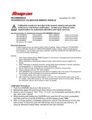
TECHANGLE November 30, 2005<br />
TECHANGLE TM Wrench CALIBRATION (NON-MEMORY MODELS)<br />
<str<strong>on</strong>g>Calibrati<strong>on</strong></str<strong>on</strong>g> events are recorded in the wrench memory and provide<br />
evidence to void factory certificati<strong>on</strong>. C<strong>on</strong>tact your <str<strong>on</strong>g>Snap</str<strong>on</strong>g>-<strong>on</strong> sales<br />
representative <str<strong>on</strong>g>for</str<strong>on</strong>g> authorized calibrati<strong>on</strong> and repair services.<br />
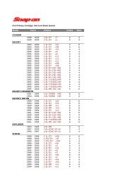
Use this procedure to calibrate the following TECHANGLE Models:<br />
ATECH2FR100 (100 ft-lb full-scale)<br />
ATECH3FR250 (250 ft-lb full-scale)<br />
Equipment Required:<br />
A torque source, accurate to 0.5% of reading or better, capable of<br />
suspending the wrench horiz<strong>on</strong>tally or vertically from the drive end. Refer<br />
to <str<strong>on</strong>g>Snap</str<strong>on</strong>g>-<strong>on</strong> Torque <str<strong>on</strong>g>Calibrati<strong>on</strong></str<strong>on</strong>g> Equipment: TTC2000, TTC2800 and<br />
VERSATEST250/600 product lines.<br />
Angle test fixture ATEST180, or equivalent, available from CDI/<str<strong>on</strong>g>Snap</str<strong>on</strong>g>-<strong>on</strong> 1-<br />
(800) 525-6319.<br />
NOTES:<br />
1. If the wrench display shows "Err0" at power <strong>on</strong>, the wrench is<br />
damaged and must be repaired be<str<strong>on</strong>g>for</str<strong>on</strong>g>e attempting calibrati<strong>on</strong>.<br />
2. When calibrating or checking flex-ratchet models, insure that the head<br />
is straight (n<strong>on</strong>-flexed).<br />
3. When calibrating, (clockwise <strong>on</strong>ly) or checking wrenches <str<strong>on</strong>g>for</str<strong>on</strong>g> torque<br />
accuracy, (clockwise or counter-clockwise) always apply load at the<br />
appropriate “V” notch near the center of the handle.<br />
4. Use TRACK mode if calibrating or checking with an electr<strong>on</strong>ic torque<br />
tester.<br />
5. Always calibrate with new “AA” cells installed.<br />
6. If the ON/RESET key is pushed any time be<str<strong>on</strong>g>for</str<strong>on</strong>g>e completing step 7 of<br />
the torque procedure or step 6 of the angle procedure, the wrench will<br />
escape from the calibrati<strong>on</strong> mode and default to the previous<br />
calibrati<strong>on</strong> parameters.<br />
7. At least 5% of full-scale torque is required to check the wrench in angle<br />
measurement mode.<br />
8. No torque is required to calibrate angle in the calibrati<strong>on</strong> mode.<br />
TORQUE <str<strong>on</strong>g>Calibrati<strong>on</strong></str<strong>on</strong>g> Procedure (per ASME B107-28)<br />
1. Push the ON key to turn the wrench <strong>on</strong>.<br />
1
2. Momentarily apply full-scale torque three times in the clockwise directi<strong>on</strong>.<br />
3. Select UNITS (Nm, ft-lb, or in-lb)<br />
4. While pushing the ON key, push the UP key <strong>on</strong>ce momentarily and then push<br />
the DOWN key until (about 3 sec<strong>on</strong>ds) the display shows "tCAL."<br />
5. With no torque applied, remove the wrench from the torque source and wait<br />
at least 15 sec<strong>on</strong>ds. Then push the UNITS key momentarily to set zero into<br />
memory. (Initiate a zero/tare of the torque source as well).<br />
6. Apply c<strong>on</strong>tinuous full-scale torque in the clockwise directi<strong>on</strong> at the “V” groove<br />
in the handle. On FR models, be sure the flex-head is straight (n<strong>on</strong>-flexed).<br />
Use the UP and DOWN keys to adjust the wrench display to match the<br />
applied torque.<br />
7. Push UNITS key (about 3 sec<strong>on</strong>ds) to accept the new calibrati<strong>on</strong> parameters<br />
into memory. The display momentarily reads "CAL" and then “End.”<br />
8. Release the torque and the wrench reverts to measurement mode. On n<strong>on</strong>-D<br />
models, use the UP and DOWN keys to PRESET the wrench to maximum.<br />
On “D” models, to retain the customer’s settings, do not change the torque or<br />
tolerance presets. (See note 7 above).<br />
9. Verify calibrati<strong>on</strong> by applying 20%, 60% and 100% of F.S. in the clockwise<br />
directi<strong>on</strong>. All readings must be within 2% of the applied torque.*<br />
10. Momentarily apply full-scale torque three times in the counter-clockwise<br />
directi<strong>on</strong>.<br />
11. Remove the wrench from the torque source, wait at least 15 sec<strong>on</strong>ds. Then<br />
push the ON key. (Initiate a zero/tare of the torque source as well).<br />
12. Verify calibrati<strong>on</strong> by applying 20%, 60% and 100% of F.S. in the counterclockwise<br />
directi<strong>on</strong>. All readings must be within 3% of the applied torque.*<br />
*For example: If the certified torque source is within 0.5% then a properly<br />
calibrated FR model should be within 2.5% of the applied torque in the<br />
clockwise directi<strong>on</strong> and within 3.5% of the applied torque in the counterclockwise<br />
directi<strong>on</strong>.<br />
ANGLE <str<strong>on</strong>g>Calibrati<strong>on</strong></str<strong>on</strong>g> Procedure<br />
1. Fixture set up: Loosen the fixture torque clutch. (Refer to fig.1 next page)<br />
Rotate the index wheel <str<strong>on</strong>g>for</str<strong>on</strong>g> 180 degree indexing. (no notches <strong>on</strong> top)<br />
2. Push the ON key to turn wrench <strong>on</strong>.<br />
3. While pushing and holding the ON key, push the DOWN key <strong>on</strong>ce<br />
momentarily and then push and hold the UP key until the display shows<br />
"ACAL."<br />
4. Install the wrench <strong>on</strong>to the ATEST180 fixture to the left as shown below,<br />
(Fig. 2). Bias the wrench up gently against the index stop. With the<br />
wrench stati<strong>on</strong>ary, push UNITS key <strong>on</strong>ce to activate angle reset (NOTE:<br />
display will show “- -“ until the wrench is held still. The display shows<br />
“turn”.<br />
5. Keeping the flex-head straight, push the index stop back (Fig. 3) and<br />
rotate the wrench in a CW directi<strong>on</strong>, 180.0°, at a rate of about 30° per<br />
2
sec<strong>on</strong>d until the index engages. Allow the wrench to hang against the<br />
stop. (Fig. 4)<br />
NOTE: “ErrA” indicates that the wrench was jerked/rotated too<br />
quickly <str<strong>on</strong>g>for</str<strong>on</strong>g> proper calibrati<strong>on</strong>, or the angle sensor offset voltage is<br />
outside nominal range. Escape the calibrati<strong>on</strong> mode (ON key) and<br />
begin procedure again.<br />
NOTE: “ErrC” indicates that angle accumulati<strong>on</strong> is outside nominal<br />
range. Escape the calibrati<strong>on</strong> mode (ON key) and begin procedure<br />
again.<br />
6. Push UNITS key (about 3 sec<strong>on</strong>ds) to accept new calibrati<strong>on</strong> parameters<br />
into memory. Display momentarily reads "CAL" and then "End" and then<br />
reverts to measurement mode last selected.<br />
7. Fixture set up: Adjust the tensi<strong>on</strong> ring <strong>on</strong> the ATEST180 fixture to<br />
approximately 10% of full-scale torque of the wrench under test. (Fig.1)<br />
8. Verify calibrati<strong>on</strong> at 45.0°, 90.0°, 135° and 180.0° in both CW and CCW<br />
directi<strong>on</strong>s using the opposite edge of the index wheel (notches <strong>on</strong> top) <strong>on</strong><br />
the ATEST180 fixture. (Fig. 5, 6,7) All readings must be within +/-1% of<br />
reading +1 degree of indexed rotati<strong>on</strong>.<br />
Fig. 1 Loosen to CAL, set 10% of F.S. to CHECK. Fig. 2 Bias wrench up against index<br />
Fig. 3 Release index stop and rotate Fig. 4 Rotate to 180 degree index and let hang<br />
3
Fig 5, 6, 7, 8 from left horiz<strong>on</strong>tal, rotate CW and stop at 45, 90, 135 and 180 degree<br />
indexes, recording the wrench display readings. Repeat in CCW directi<strong>on</strong>.<br />
4