BICYCLE ASSEMBLY GUIDE - Evans Cycles
BICYCLE ASSEMBLY GUIDE - Evans Cycles
BICYCLE ASSEMBLY GUIDE - Evans Cycles

Create successful ePaper yourself
Turn your PDF publications into a flip-book with our unique Google optimized e-Paper software.
<strong>BICYCLE</strong> <strong>ASSEMBLY</strong> <strong>GUIDE</strong><br />
This guide is designed to assist you with unpacking and assembling your bicycle. Your bicycle<br />
has been fully assembled and tested before repackaging. By carefully following the steps in<br />
this guide you should be able to have your bicycle ready for use in just a few minutes. Please<br />
retain the original box and packaging in the event that you need to return your bicycle to us.<br />
0870 600 0908
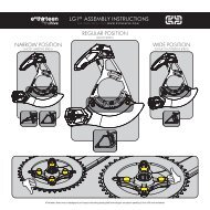
1 - HANDLEBARS & STEM<br />
First identify which of the following type of stem is fi tted to your bicycle.<br />
A-HEADSET SYSTEM<br />
The stem clamps on the<br />
outside of the fork steerer<br />
QUILL SYSTEM<br />
The stem is slotted into<br />
the fork steerer tube<br />
A-HEADSET SYSTEM<br />
• Using the supplied Allen key fi rst slacken off the bolts on the side of the stem (Image A.).<br />
• Twist the stem so it is in line with the front wheel (Image B.).<br />
• Using the allen key tighten the top bolt just enough to get rid of any play in the headset.<br />
To check for play rock the bike forward and back with the front brake applied, if there<br />
is movement within the headset then tighten the top bolt more. Do not over tighten this<br />
bolt, it needs to be free enough to allow the handlebar to turn unrestricted (Image C.).<br />
• Retighten the bolts on the side of the stem (Image A.).<br />
A. Slackening and tightening<br />
stem bolts<br />
B. Twist stem into position C. Tighten the top bolt<br />
QUILL SYSTEM<br />
• First slacken off the top stem bolt by turning anti-clockwise no more than 3 revolutions<br />
(Image D.).<br />
• Twist the stem so it is in line with the front wheel (Image E.).<br />
• Finish by retightening the top stem bolt (Image D.).<br />
• Pay attention to the min insert mark on the stem, do not raise the stem above this mark<br />
(Image F.).<br />
D. Slackening and tightening<br />
top bolt<br />
<br />
E. Twist stem into position F. Minimum insertion mark
G. Position handlebars so the<br />
levers are 45° to the ground<br />
DO NOT RIDE YOUR BIKE WITHOUT CHECKING YOUR<br />
HANDLEBARS & STEM ARE FULLY TIGHTENED!<br />
HANDLEBARS (BOTH TYPES OF STEM)<br />
• Finally with both types of stem make sure that the bars are in the correct position with<br />
the brake levers at 45 degrees to the ground (Image G.).<br />
• Tighten stem cap bolts (Image H.).<br />
45°<br />
H. Tighten stem cap bolts<br />
CORRECT FORK POSITION<br />
• Ensure forks are correctly positioned with disc brakes (Image I.) at the rear of the fork and<br />
rim brakes (Image J.) at the front of the fork.<br />
<br />
I. Position the fork so disc brake<br />
is at the rear<br />
✘ ✘<br />
✔ ✔<br />
<br />
J. Position the fork so rim brake<br />
is at the front<br />
0870 600 0908
YOUR <strong>BICYCLE</strong> MUST BE PROPERLY ASSEMBLED AND CHECKED BEFORE RIDING. EVANS<br />
CYCLES ACCEPT NO RESPONSIBILITY FOR INJURY OR DAMAGE DUE TO FAULTY <strong>ASSEMBLY</strong>.<br />
FOR MORE DETAILED INFORMATION PLEASE REFER TO YOUR OWNERS HANDBOOK AND ANY<br />
ADDITIONAL LITERATURE SUPPLIED WITH YOUR <strong>BICYCLE</strong>. IF YOU ARE IN ANY DOUBT PLEASE<br />
CONTACT US FOR ASSISTANCE. PLEASE NOTE THAT FAILURE TO ENSURE YOUR CYCLE IS<br />
PROPERLY ASSEMBLED MAY LEAD TO INJURY AND INVALIDATE ANY WARRANTY CLAIM.<br />
<strong>ASSEMBLY</strong> UNDERTAKEN WITHOUT PROFESSIONAL ASSISTANCE IS AT THE OWNERS RISK.<br />
Re-order code: YLEAF018<br />
2 - PEDALS<br />
IDENTIFY THE LEFT AND RIGHT PEDALS. DO NOT CONFUSE THE LEFT AND RIGHT<br />
PEDALS – THEY ARE DIFFERENT. The right pedal is fi tted to the drive side (the side with<br />
the chain and gears). Both pedals will be clearly marked which side they are for. They are<br />
often stamped L or R at the end of the axle.<br />
LEFT PEDAL RIGHT PEDAL<br />
LEFT PEDAL<br />
• Take the LEFT pedal and FINGER TIGHTEN this into the left hand crank arm by turning<br />
the pedal axle ANTI-CLOCKWISE (Image K.). After a few turns you can use your spanner<br />
to fully tighten it onto the crank (Image M.).<br />
RIGHT PEDAL<br />
• Take the RIGHT pedal and FINGER TIGHTEN this into the right hand (drive side) crank<br />
arm by turning the pedal axle CLOCKWISE (Image L.). After a few turns you can use your<br />
spanner to fully tighten it onto the crank (Image M.).<br />
K. Left pedal<br />
fi nger tighten anti-clockwise<br />
↺ ↻<br />
L. Right pedal<br />
fi nger tighten clockwise<br />
WARNING!<br />
M. Tighten with a pedal spanner<br />
DO NOT FORCE YOUR PEDALS ON! ALWAYS FINGER TIGHTEN FIRST.<br />
ATTEMPTING TO FIT A PEDAL TO THE INCORRECT CRANK ARM<br />
WILL VOID YOUR WARRANTY