Helical Gearboxes RD - Varvel SpA
Helical Gearboxes RD - Varvel SpA
Helical Gearboxes RD - Varvel SpA

Create successful ePaper yourself
Turn your PDF publications into a flip-book with our unique Google optimized e-Paper software.
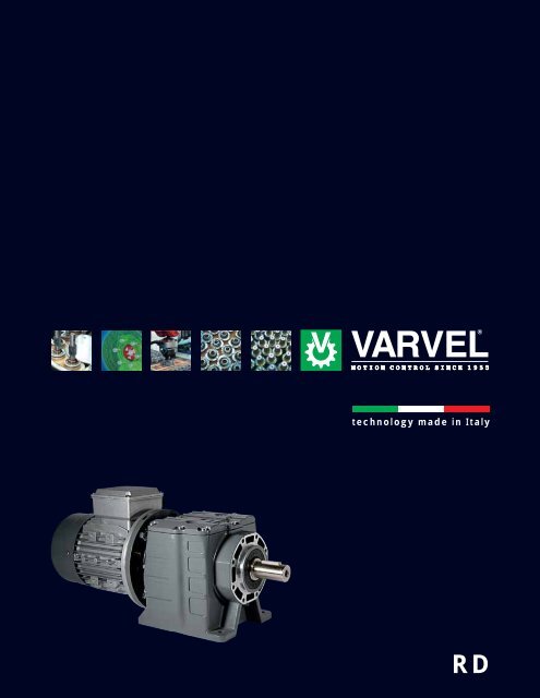
technology made in Italy<br />
<strong>RD</strong>
*<br />
Since 1955 <strong>Varvel</strong> has been making speed reducers and<br />
variators for light industry applications. Reliable partner in<br />
power transmission equipment offers also customized solutions<br />
always according to a socially responsible company values.<br />
Modularity and flexibility lead <strong>Varvel</strong> products by a unique kit<br />
form, common to all gearbox series. This feature allows distributors<br />
an easier job to set up required products in few minutes.<br />
Technology Made in Italy<br />
Technologie Made in Italy<br />
Depuis 1955 <strong>Varvel</strong> projette et réalise réducteur et variateur<br />
mécaniques dédiés à la petite et moyenne industrie. Partner<br />
fiable dans la production et la vente d’organes de transmission<br />
grace à un très bon niveau de service, <strong>Varvel</strong> offre également<br />
des solutions personnalisées tout en respectant les valeurs de<br />
l'entreprise socialement responsable. Modularité et flexibilité<br />
guide la conception des produits <strong>Varvel</strong> en réalisant des kits<br />
communs pour toutes les familles de réducteurs, favorisant<br />
ainsi l’activité des distributeurs et revendeurs qui peuvent<br />
réaliser en quelques minutes le produit sur demande du client.<br />
Tecnología Made in Italy<br />
Desde 1955 <strong>Varvel</strong> proyecta y fabrica reductores y variadores<br />
de velocidad para aplicaciones de pequeña y mediana potencia.<br />
Socio fiable para la producción y venta de órganos de transmisión<br />
gracias a un elevado nivel de servicio, ofrece también soluciones<br />
personalizadas actuando con el respeto a los valores de la<br />
empresa socialmente responsable. Modularidad y flexibilidad<br />
guían el diseño de los productos <strong>Varvel</strong> mediante la realización<br />
de kits comunes a toda la familia de reductores, facilitando así la<br />
gestión de los distribuidores y revendedores que pueden configurar<br />
en pocos minutos el producto solicitado por cada cliente.<br />
* VS made in China
<strong>Helical</strong> <strong>Gearboxes</strong><br />
<strong>RD</strong>
<strong>Helical</strong> <strong>Gearboxes</strong> <strong>RD</strong><br />
PRODUCT DESCRIPTION<br />
Multipurpose housing<br />
Foot & Foot/Flange Mountings<br />
One housing for 2- & 3-stages<br />
Housing & Covers Input<br />
Aluminium die cast (5 sizes) NEMA and IEC<br />
Cast iron (2 sizes) motor adapters and<br />
Universal elastic coupling<br />
Gearing Oil seals<br />
20MnCr5 alloy steel Nitrile Butadiene Rubber -NBR<br />
Case hardened as standard;<br />
Profile ground or shaved Viton and Silicon on request<br />
Bearings Output<br />
Ball or roller types Solid shafts<br />
according to sizes imperial and metric<br />
and technical requirements<br />
CONTENTS<br />
Product Description .............................................................. 2-3<br />
Symbols & Formulas ..................................................................3<br />
Modular System ..................................................................... 4-5<br />
Elastic Coupling “G” ...................................................................6<br />
Elastic Coupling “G” Selection ...................................................7<br />
NEMA Flanges and Elastic Couplings .......................................8<br />
IEC Flanges and Elastic Couplings ...........................................9<br />
Electronic Catalogue - 3D-Models - 2D-Drawings ...................10<br />
Order Designation ....................................................................11<br />
Input Arrangements .................................................................12<br />
Mounting Positions .................................................................13<br />
Service Factors ................................................................. 14-16<br />
External Loads ........................................................................17<br />
Components & Conversion Factors .........................................18<br />
Ratings<br />
<strong>RD</strong> 02 - 03 ..............................................................................19<br />
<strong>RD</strong> 12 - 13 ..............................................................................20<br />
<strong>RD</strong> 22 - 23 ..............................................................................21<br />
<strong>RD</strong> 32 - 33 ..............................................................................22<br />
<strong>RD</strong> 42 - 43 ..............................................................................23<br />
<strong>RD</strong> 52 - 53 ...............................................................................24<br />
<strong>RD</strong> 62 - 63 ...............................................................................25<br />
Lubrication<br />
Synthetic long-life oil Grade ISO VG 320<br />
No oil plugs<br />
In-house filling<br />
- 2 -<br />
Dimensions<br />
<strong>RD</strong> 02 - 03 ......................................................................... 26-27<br />
<strong>RD</strong> 12 - 13 ......................................................................... 28-29<br />
<strong>RD</strong> 22 - 23 ......................................................................... 30-31<br />
<strong>RD</strong> 32 - 33 ......................................................................... 32-33<br />
<strong>RD</strong> 42 - 43 .......................................................................... 34-35<br />
<strong>RD</strong> 52 - 53 .......................................................................... 36-37<br />
<strong>RD</strong> 62 - 63 .......................................................................... 38-39<br />
Summary of “Operation and Manual Instructions”................... 40
- 3 -<br />
<strong>Helical</strong> <strong>Gearboxes</strong> <strong>RD</strong><br />
PRODUCT DESCRIPTION<br />
The helical gearboxes Series <strong>RD</strong> feature a one-piece cast housing complete with inner support to accommodate 2 or 3 gear stages<br />
into the same casing. Manufactured to latest ISO engineering design specifications the housing is checked by computer-aided<br />
structural analysis for deflection and stress distribution.<br />
Significant strains caused by the effects of torque and external loads do not deflect the monolithic ribwork of the housing, which<br />
significantly improves the integrity of the sealed surfaces.<br />
The helical gearboxes, Series <strong>RD</strong> are manufactured in B3 base mounted configuration; they can be easily converted to B5 flange<br />
mounting by fitting of the appropriate additional adaptor flange onto the footed body.<br />
Single-setup machining on state-of-the-art CNC production lines, the most recent calculation techniques and process controls give<br />
superior operational reliability, maximum output torques, high overhung and thrust load capacity, and long working life-time.<br />
D [in] Transmission element PCD<br />
Fr [lb] Application overhung load (OHL)<br />
Fr1 [lb] Catalogue input overhung load (input OHL)<br />
Fr2 [lb] Catalogue output overhung load (output OHL)<br />
Fr2b(x) [lb] Permissible OHL at position 'X' on output shaft, bearing lifetime condition<br />
Fr2s(x) [lb] Permissible OHL same as Fr2b(x), shaft bending and torsional stress condition<br />
SF Service factor<br />
in Nominal reduction ratio<br />
ir Actual reduction ratio<br />
J1 [ft 2 -lb] Gearbox moment of inertia at input shaft<br />
J2 [ft 2 -lb] Application moment of inertia<br />
Jm [ft 2 -lb] Motor moment of inertia<br />
k(a) Mass acceleration factor<br />
k(t) Transmission element factor<br />
Lub H/V [pt] Lubricant [pt]: H = horizontal mounting / V = vertical mounting<br />
M2 [in-lb] Gearbox maximunm output torque<br />
M(app) [in-lb] Application torque<br />
n1 [RPM] Input speed<br />
n2 [RPM] Output speed<br />
P1 [HP] Input power @ 60Hz<br />
W [lb] Weight: mounting B3-H & average reduction ratio<br />
η<br />
Efficiency: 0.96 - 2-stage units<br />
0.94 - 3-stage units<br />
SYMBOLS & FORMULAS<br />
M2<br />
FS <br />
M(app)<br />
1800 P1<br />
<br />
M2<br />
<br />
n2<br />
M2<br />
n2<br />
P1<br />
1800
<strong>Helical</strong> <strong>Gearboxes</strong> <strong>RD</strong><br />
MODULAR SYSTEM<br />
- 4 -
- 5 -<br />
<strong>Helical</strong> <strong>Gearboxes</strong> <strong>RD</strong><br />
MODULAR SYSTEM
<strong>Helical</strong> <strong>Gearboxes</strong> <strong>RD</strong><br />
ELASTIC COUPLING “G”<br />
Reducer half-coupling<br />
Material: steel alloy 20MnCr5<br />
Input shaft built-in<br />
Two bearing set<br />
Unchanged casing dimensions<br />
Spider<br />
External tooth connection<br />
Material: Thermoplastic Elastomer<br />
Elastollan ® TPU - Polyurethane<br />
Hytrel ® TPE - Polyester<br />
Hardness<br />
- TPU 98 Shore A<br />
- TPE 72 Shore D<br />
Temperature<br />
- TPU -4 / +167 °F (-20/+75 °C)<br />
- TPE -22 / +212 °F (-30/+100°C)<br />
Motor half-coupling<br />
Material:<br />
- Aluminium die cast (G3, G5, G6)<br />
- Alloy steel 36SMnPb14 (GS8)<br />
- Alloy steel C43 on demand (GS3, GS5, GS6)<br />
Dynamic balancing<br />
Fitting:<br />
- Clamp (G3, G5, G6)<br />
- Key (GS3, GS5, GS6, GS8)<br />
Bores:<br />
- NEMA C / TC<br />
- IEC 72 / N42948<br />
Advantages:<br />
One gearbox only for each reduction ratio<br />
Greater flexibility<br />
Increased stock rotation<br />
Fretting corrosion elimination between key and keyway<br />
Zero backlash in gearbox/motor connection<br />
Allowed angular misalignment 1° max<br />
High torsional rigidity<br />
High vibration damping<br />
Input flanges:<br />
Material:<br />
- Aluminium up to IEC112 and NEMA 180TC<br />
- Cast iron from IEC 132 and NEMA 210TC<br />
- 6 -
Coupling<br />
Size<br />
G3<br />
G5<br />
G6<br />
G8<br />
IEC<br />
NEMA<br />
IEC<br />
NEMA<br />
IEC<br />
NEMA<br />
IEC<br />
NEMA<br />
IEC<br />
NEMA<br />
Kit<br />
Code<br />
KG3.009<br />
KG3.011<br />
KG3.014<br />
KG3.N42<br />
KG3.N48<br />
KG5.009<br />
KG5.011<br />
KG5.014<br />
KG5.019<br />
KG5.024<br />
KG5.N48<br />
KG5.N56<br />
KG5.N140<br />
KG6.014<br />
KG6.019<br />
KG6.024<br />
KG6.028<br />
KG6.N56<br />
KG6.N140<br />
KG6.N180<br />
* KGS8.19<br />
* KGS8.24<br />
* KGS8.28<br />
* KGS8.38<br />
* KGS8.42<br />
* KGS8.48<br />
* KGS8.N056<br />
* KGS8.N140<br />
* KGS8.N180<br />
* KGS8.N210<br />
Mt - Screw locking torque<br />
Mt1 - Transmissible torque with key<br />
Mt2 - Transmissible torque without key<br />
* - Coupling GS8: steel and key fit<br />
<strong>RD</strong><br />
Size<br />
03<br />
03<br />
03<br />
03<br />
03<br />
02-12-13-23<br />
02-12-13-23<br />
02-12-13-23<br />
02-12-23<br />
12-23<br />
02<br />
02-12-13-23<br />
12-23<br />
22-32-33-42-43<br />
22-32-33-42-43<br />
22-32-33-42-43<br />
22-32-42<br />
22-32-33-42-43<br />
22-32-33-42-43<br />
22-32-42-43<br />
52-53-62-63<br />
52-53-62-63<br />
52-53-62-63<br />
52-62-63<br />
52-62<br />
52-62<br />
52-53-62-63<br />
52-53-62-63<br />
52-53-62-63<br />
52-53-62-63<br />
Mt<br />
[Nm]<br />
4.5 - 6<br />
4.5 - 6<br />
7 - 8.5<br />
4.5 - 6<br />
4.5 - 6<br />
8.9 -<br />
10<br />
15.3 - 18<br />
15<br />
Mt1<br />
[Nm]<br />
- 7 -<br />
15<br />
15<br />
28<br />
16<br />
18<br />
14<br />
15<br />
30<br />
40<br />
70<br />
30<br />
45<br />
60<br />
60<br />
90<br />
130<br />
180<br />
50<br />
85<br />
200<br />
150<br />
250<br />
350<br />
500<br />
500<br />
500<br />
140<br />
200<br />
300<br />
500<br />
Mt2<br />
[Nm]<br />
8 - 10<br />
8 - 10<br />
18 - 22<br />
8 - 10<br />
10 - 12<br />
<strong>Helical</strong> <strong>Gearboxes</strong> <strong>RD</strong><br />
ELASTIC COUPLING “G” SELECTION<br />
A<br />
[mm]<br />
B<br />
[mm]<br />
11 19<br />
8 - 10<br />
8 - 10<br />
12 - 17<br />
20 - 25<br />
30 - 40 14.5 23<br />
20 - 24<br />
30 - 35<br />
40 - 45<br />
D1<br />
[mm<br />
30<br />
30<br />
36<br />
30<br />
36<br />
45<br />
45<br />
45<br />
45<br />
52<br />
40<br />
45<br />
52<br />
30 - 40<br />
50 - 65<br />
85 - 100<br />
100 - 120 19.5 31.5 58<br />
- - -<br />
- - -<br />
- - -<br />
- - -<br />
- - -<br />
- - -<br />
- - -<br />
- - -<br />
- - - 35 51 79<br />
- - -<br />
- - -<br />
- - -<br />
- - -<br />
D2<br />
[mm /<br />
inch]<br />
9<br />
11<br />
14<br />
3/8"<br />
1/2"<br />
9<br />
11<br />
14<br />
19<br />
24<br />
1/2"<br />
5/8"<br />
7/8"<br />
14<br />
19<br />
24<br />
28<br />
5/8"<br />
7/8"<br />
1-1/8"<br />
19<br />
24<br />
28<br />
38<br />
42<br />
48<br />
5/8"<br />
7/8"<br />
1-1/8"<br />
1-3/8"<br />
Coupling<br />
ID#<br />
309<br />
311<br />
314<br />
3N42<br />
3N48<br />
509<br />
511<br />
514<br />
519<br />
524<br />
5N48<br />
5N56<br />
5N140<br />
614<br />
619<br />
624<br />
628<br />
6N56<br />
6N140<br />
6N180<br />
819<br />
824<br />
828<br />
838<br />
842<br />
848<br />
8N56<br />
8N140<br />
8N180<br />
8N210
<strong>Helical</strong> <strong>Gearboxes</strong> <strong>RD</strong><br />
NEMA FLANGES & ELASTIC COUPLINGS<br />
<strong>RD</strong> Flange NEMA<br />
<strong>RD</strong> 02<br />
<strong>RD</strong> 03<br />
FM 40<br />
48 C<br />
56 C<br />
42 C<br />
48 C<br />
- 8 -<br />
Kit Code Coupling<br />
Flange Type Kit Code<br />
K531.227.N48<br />
K531.227.N56<br />
K531.227.N48<br />
K531.227.N48<br />
G5 ø 1/2”<br />
G5 ø 5/8”<br />
G3 ø 3/8”<br />
G3 ø 1/2”<br />
KG5.N48<br />
KG5.N56<br />
KG3.N42<br />
KG3.N48<br />
<strong>RD</strong> 12<br />
56 C<br />
140 TC<br />
K532.227.N56<br />
K532.227.N56<br />
G5 ø 5/8”<br />
G5 ø 7/8”<br />
KG5.N56<br />
KG5.N140<br />
FM 50<br />
<strong>RD</strong> 13 56 C K532.227.N56 G5 ø 5/8” KG5.N56<br />
<strong>RD</strong> 22<br />
<strong>RD</strong> 23<br />
<strong>RD</strong> 32<br />
<strong>RD</strong> 33<br />
<strong>RD</strong> 42<br />
<strong>RD</strong> 43<br />
<strong>RD</strong> 52<br />
<strong>RD</strong> 53<br />
<strong>RD</strong> 62<br />
<strong>RD</strong> 63<br />
FM 70<br />
FM 70<br />
FM 85<br />
FM 150<br />
FM 150<br />
* - Coupling GS8: steel and key fit<br />
56 C<br />
140 C<br />
180 C<br />
56 C<br />
140 C<br />
56 C<br />
140 TC<br />
180 TC<br />
56 C<br />
140 TC<br />
56 C<br />
140 TC<br />
180 TC<br />
56 C<br />
140 TC<br />
180 TC<br />
56 C<br />
140 TC<br />
180 TC<br />
210 TC<br />
56 C<br />
140 TC<br />
180 TC<br />
210 TC<br />
56 C<br />
140 TC<br />
180 TC<br />
210 TC<br />
56 C<br />
140 TC<br />
180 TC<br />
210 TC<br />
K533.227.N56<br />
K533.227.N56<br />
K533.227.N180<br />
K533.227.N56<br />
K533.227.N56<br />
K533.227.N56<br />
K533.227.N56<br />
K533.227.N180<br />
K533.227.N56<br />
K533.227.N56<br />
K534.227.N56<br />
K534.227.N56<br />
K534.227.N180<br />
K534.227.N56<br />
K534.227.N56<br />
K534.227.N180<br />
K537.227.N56<br />
K537.227.N56<br />
K537.227.N180<br />
K537.227.N180<br />
K537.227.N56<br />
K537.227.N56<br />
K537.227.N180<br />
K537.227.N180<br />
K537.227.N56<br />
K537.227.N56<br />
K537.227.N180<br />
K537.227.N180<br />
K537.227.N56<br />
K537.227.N56<br />
K537.227.N180<br />
K537.227.N180<br />
G6 ø 5/8”<br />
G6 ø 7/8”<br />
G6 ø 1-1/8”<br />
G5 ø 5/8”<br />
G5 ø 7/8”<br />
G6 ø 5/8”<br />
G6 ø 7/8”<br />
G6 ø 1-1/8”<br />
G6 ø 5/8”<br />
G6 ø 7/8”<br />
G6 ø 5/8”<br />
G6 ø 7/8”<br />
G6 ø 1-1/8”<br />
G6 ø 5/8”<br />
G6 ø 7/8”<br />
G6 ø 1-1/8”<br />
* GS8 ø 5/8”<br />
* GS8 ø 7/8”<br />
* GS8 ø 1-1/8”<br />
* GS8 ø 1-3/8”<br />
* GS8 ø 5/8”<br />
* GS8 ø 7/8”<br />
* GS8 ø1-1/8”<br />
* GS8 ø 1-3/8”<br />
* GS8 ø 5/8”<br />
* GS8 ø 7/8”<br />
* GS8 ø 1-1/8”<br />
* GS8 ø 1-3/8”<br />
* GS8 ø 5/8”<br />
* GS8 ø 7/8”<br />
* GS8 ø 1-1/8”<br />
* GS8 ø 1-3/8”<br />
KG6.N56<br />
KG6.N140<br />
KG6.N180<br />
KG5.N56<br />
KG5.N140<br />
KG6.N56<br />
KG6.N140<br />
KG6.N180<br />
KG6.N56<br />
KG6.N140<br />
KG6.N56<br />
KG6.N140<br />
KG6.N180<br />
KG6.N56<br />
KG6.N140<br />
KG6.N180<br />
KGS8.N56<br />
KGS8.N140<br />
KGS8.N180<br />
KGS8.N210<br />
KGS8.N56<br />
KGS8.N140<br />
KGS8.N180<br />
KGS8.N210<br />
KGS8.N56<br />
KGS8.N140<br />
KGS8.N180<br />
KGS8.N210<br />
KGS8.N56<br />
KGS8.N140<br />
KGS8.N180<br />
KGS8.N210
<strong>RD</strong> Flange IEC<br />
<strong>RD</strong> 02 FM 40 IEC56<br />
IEC63<br />
IEC71<br />
IEC80<br />
<strong>RD</strong> 03 FM 40 IEC56<br />
IEC63<br />
IEC71<br />
<strong>RD</strong> 12 FM 50 IEC56<br />
IEC63<br />
IEC71<br />
IEC80<br />
IEC90<br />
<strong>RD</strong> 13 FM 50 IEC56<br />
IEC63<br />
IEC71<br />
<strong>RD</strong> 22 FM 70 IEC71<br />
IEC80<br />
IEC90<br />
IEC 100/112<br />
<strong>RD</strong> 23 FM 70 IEC63<br />
IEC71<br />
IEC80<br />
IEC90<br />
<strong>RD</strong> 32<br />
<strong>RD</strong> 33<br />
<strong>RD</strong> 42<br />
<strong>RD</strong> 43<br />
<strong>RD</strong> 52 FM 130<br />
&<br />
FM 150<br />
FM 70 IEC71<br />
IEC80<br />
IEC90<br />
* IEC 100/112<br />
FM 85 IEC71<br />
IEC80<br />
IEC90<br />
** IEC 100/112<br />
IEC 80<br />
IEC 90<br />
IEC 100/112<br />
IEC 132<br />
IEC 160<br />
IEC 180<br />
<strong>RD</strong> 53 FM 130 IEC 80<br />
IEC 90<br />
IEC 100/112<br />
<strong>RD</strong> 62 FM 130<br />
&<br />
FM 150<br />
<strong>RD</strong> 63 FM 130<br />
&<br />
FM 150<br />
* - IEC100/112: not for <strong>RD</strong>33<br />
** - IEC112: not for <strong>RD</strong>43<br />
*** - Coupling GS8: steel and key fit<br />
IEC 80<br />
IEC 90<br />
IEC 100/112<br />
IEC 132<br />
IEC 160<br />
IEC 180<br />
IEC 80<br />
IEC 90<br />
IEC 100/112<br />
IEC 132<br />
- 9 -<br />
Kit Code<br />
<strong>Helical</strong> <strong>Gearboxes</strong> <strong>RD</strong><br />
IEC FLANGES & ELASTIC COUPLINGS<br />
Coupling<br />
Flange B5 Flange B14 Type Kit Code<br />
K531.206.120<br />
K531.206.140<br />
K531.206.160<br />
- - -<br />
K531.206.120<br />
K531.206.140<br />
K531.206.160<br />
K532.206.120<br />
K532.206.140<br />
K532.206.160<br />
K532.206.200<br />
K532.206.200<br />
K532.206.120<br />
K532.206.140<br />
K532.206.160<br />
K533.206.160<br />
K533.206.200<br />
K533.206.200<br />
K533.206.250<br />
K533.206.140<br />
K533.206.160<br />
K533.206.200<br />
K533.206.200<br />
K533.206.160<br />
K533.206.200<br />
K533.206.200<br />
K533.206.250<br />
K534.206.160<br />
K534.206.200<br />
K534.206.200<br />
K534.206.250<br />
K536.206.200<br />
K536.206.200<br />
K536.206.250<br />
K537.206.300<br />
K565.206.350<br />
K565.206.350<br />
K536.206.200<br />
K536.206.200<br />
K536.206.250<br />
K536.206.200<br />
K536.206.200<br />
K536.206.250<br />
K537.206.300<br />
K565.206.350<br />
K565.206.350<br />
K536.206.200<br />
K536.206.200<br />
K536.206.250<br />
K537.206.300<br />
K531.206.080<br />
K531.206.090<br />
K531.206.105<br />
K531.206.120<br />
K531.206.080<br />
K531.206.090<br />
K531.206.105<br />
- - -<br />
K532.206.090<br />
K532.206.105<br />
K532.206.120<br />
K532.206.140<br />
- - -<br />
K532.206.090<br />
K532.206.105<br />
K533.206.105<br />
K533.206.120<br />
K533.206.140<br />
K533.206.160<br />
- - -<br />
K533.206.105<br />
K533.206.120<br />
K533.206.140<br />
K533.206.105<br />
K533.206.120<br />
K533.206.140<br />
K533.206.160<br />
- - -<br />
K534.206.120<br />
K534.206.140<br />
K534.206.160<br />
- - -<br />
- - -<br />
- - -<br />
K536.206.200<br />
K536.206.250<br />
- - -<br />
- - -<br />
- - -<br />
- - -<br />
- - -<br />
- - -<br />
- - -<br />
K536.206.200<br />
K536.206.250<br />
- - -<br />
- - -<br />
- - -<br />
- - -<br />
K536.206.200<br />
G5 ø09<br />
G5 ø11<br />
G5 ø14<br />
G5 ø19<br />
G3 ø09<br />
G3 ø11<br />
G3 ø14<br />
G5 ø09<br />
G5 ø11<br />
G5 ø14<br />
G5 ø19<br />
G5 ø24<br />
G5 ø09<br />
G5 ø11<br />
G5 ø14<br />
G6 ø14<br />
G6 ø19<br />
G6 ø24<br />
G6 ø28<br />
G5 ø11<br />
G5 ø14<br />
G5 ø19<br />
G5 ø24<br />
G6 ø14<br />
G6 ø19<br />
G6 ø24<br />
G6 ø28<br />
G6 ø14<br />
G6 ø19<br />
G6 ø24<br />
G6 ø28<br />
*** GS8 ø19<br />
*** GS8 ø24<br />
*** GS8 ø28<br />
*** GS8 ø38<br />
*** GS8 ø42<br />
*** GS8 ø48<br />
*** GS8 ø19<br />
*** GS8 ø24<br />
*** GS8 ø28<br />
*** GS8 ø19<br />
*** GS8 ø24<br />
*** GS8 ø28<br />
*** GS8 ø38<br />
*** GS8 ø42<br />
*** GS8 ø48<br />
*** GS8 ø19<br />
*** GS8 ø24<br />
*** GS8 ø28<br />
*** GS8 ø38<br />
KG5.009<br />
KG5.011<br />
KG5.014<br />
KG5.019<br />
KG3.009<br />
KG3.011<br />
KG3.014<br />
KG5.009<br />
KG5.011<br />
KG5.014<br />
KG5.019<br />
KG5.024<br />
KG5.009<br />
KG5.011<br />
KG5.014<br />
KG6.014<br />
KG6.019<br />
KG6.024<br />
KG6.028<br />
KG5.011<br />
KG5.014<br />
KG5.019<br />
KG5.024<br />
KG6.014<br />
KG6.019<br />
KG6.024<br />
KG6.028<br />
KG6.014<br />
KG6.019<br />
KG6.024<br />
KG6.028<br />
KGS8.019<br />
KGS8.024<br />
KGS8.028<br />
KGS8.038<br />
KGS8.042<br />
KGS8.048<br />
KGS8.019<br />
KGS8.024<br />
KGS8.028<br />
KGS8.019<br />
KGS8.024<br />
KGS8.028<br />
KGS8.038<br />
KGS8.042<br />
KGS8.048<br />
KGS8.019<br />
KGS8.024<br />
KGS8.028<br />
KGS8.038
<strong>Helical</strong> <strong>Gearboxes</strong> <strong>RD</strong><br />
ELECTRONIC CATALOGUE - 3D-MODELS - 2D-DRAWINGS<br />
Modularity and flexibility have been leading the design of <strong>Varvel</strong> products since 2000. The gearbox-kit concept was<br />
carried out allowing anyone to assemble the unit in a few minutes with standard tooling.<br />
This feature provides the highest flexibility to <strong>Varvel</strong>’s distributors and resellers who - thanks to a limited kit selection -<br />
are able to immediately configure the required product.<br />
VARSIZE ® selection programme, available from our site<br />
www.varvel.com<br />
allows a friendly sizing of <strong>Varvel</strong> product range.<br />
2D/3D Drawings<br />
A guided selection allows 2D/3D models to be downloaded for the most popular CAD systems.<br />
Guided selection<br />
This service returns a list of applicable product configurations upon a given sequence of application parameters<br />
(power, output torque, rpm, service factor etc.); a PDF data sheet featuring performance data and dimensional<br />
drawings is generated for each configuration, as well as the 3D model and 2D drawings.<br />
- 10 -
- 11 -<br />
<strong>Helical</strong> <strong>Gearboxes</strong> <strong>RD</strong><br />
Example: F<strong>RD</strong>32/B3-H4 31.5 N56 AU35 O<strong>RD</strong>ER DESIGNATION<br />
F <strong>RD</strong> 52 B3-H4 31.5 N56 AU DFU<br />
TYPE MOUNTING POSITION<br />
<strong>RD</strong> - <strong>Helical</strong> gearbox<br />
Page 5<br />
B3 - Foot mounting<br />
B5 - Flange mounting<br />
OUTPUT<br />
FLANGE mm<br />
INPUT TYPE SIZE REDUCTION RATIO 1: MOTOR ADAPTER OUTPUT SHAFT DIA.<br />
M - Motorized Unit<br />
F - Motor Flange<br />
S - Without Mtr Flange<br />
nil - Solid input<br />
A) - 2-stages<br />
B) - 3-stages<br />
A) B) A) B) NEMA in<br />
02 03 2.5 40 N42 0.625“<br />
12 13 3.15 50 N48 0.750”<br />
22 23 4.0 63 N56 1.000“<br />
32 33 5.0 80 N140 1.250“<br />
42 43 6.3 100 N180 1.375”<br />
120<br />
140<br />
160<br />
. . .<br />
300<br />
350<br />
52 53 8.0 125 N210 1.625“ / 2.125”<br />
62 63 10.0 160 2.125“ / 2.375”<br />
12.5 200<br />
16.0 250<br />
20.0 315<br />
25.0 400<br />
31.5 500<br />
40 630<br />
50<br />
63
<strong>Helical</strong> <strong>Gearboxes</strong> <strong>RD</strong><br />
INPUT ARRANGEMENTS<br />
NEMA INPUT<br />
F<strong>RD</strong><br />
NEMA<br />
02 03 12 13 22 23 32 33 42 43 52 53 62 63<br />
42 - - G3 - - - - - - - - - - - - - - - - - - - - - - - -<br />
48 G5 G3 - - - - - - - - - - - - - - - - - - - - - - - -<br />
56 G5 - - G5 G5 G6 G5 G6 G6 G6 G6 G8 G8 G8 G8<br />
140 - - - - G5 - - G6 G5 G6 G6 G6 G6 G8 G8 G8 G8<br />
180 - - - - - - - - G6 - - G6 - - G6 G6 G8 G8 G8 G8<br />
210 - - - - - - - - - - - - - - - - - - - - G8 G8 G8 G8<br />
G3, G5, G6 = Elastic coupling 'G' input, aluminium die cast type<br />
GS8 = Elastic coupling 'G' input, steel type<br />
IEC INPUT<br />
F<strong>RD</strong><br />
IEC<br />
02 03 12 13 22 23 32 33 42 43 52 53 62 63<br />
56 □ ■ □ ■ □ ■ □ ■ - - - - - - - - - - - - - - - - - - - -<br />
63 □ ■ □ ■ □ ■ □ ■ - - □ ■ - - - - - - - - - - - - - - - -<br />
71 □ ■ □ ■ □ ■ □ ■ □ ■ □ ■ □ ■ □ ■ □ ■ □ ■ - - - - - - - -<br />
80 □ ■ - - □ ■ - - □ ■ □ ■ □ ■ □ ■ □ ■ □ ■ □ ■ □ ■ □ ■ □ ■<br />
90 - - - - □ ■ - - □ ■ □ ■ □ ■ □ ■ □ ■ □ ■ □ ■ □ ■ □ ■ □ ■<br />
100 - - - - - - - - □ ■ - - □ ■ - - □ ■ - - □ ■ □ ■ □ ■ □ ■<br />
112 - - - - - - - - □ ■ - - □ ■ - - □ ■ - - □ ■ □ ■ □ ■ □ ■<br />
132 - - - - - - - - - - - - - - - - ■ - - □ ■ - - □ ■ □ ■<br />
160 - - - - - - - - - - - - - - - - - - - - □ ■ - - □ ■ - -<br />
180 - - - - - - - - - - - - - - - - - - - - □ ■ - - □ ■ - -<br />
□ = IEC with G-Coupling (standard)<br />
■ = IEC with quill input (on demand)<br />
- 12 -
B3<br />
Foot mounting<br />
B5<br />
Flange mounting<br />
H2 H1 V6<br />
V5 H4<br />
H3<br />
H2 H1 V6<br />
V5 H4<br />
H3<br />
- 13 -<br />
<strong>Helical</strong> <strong>Gearboxes</strong> <strong>RD</strong><br />
MOUNTING POSITIONS
<strong>Helical</strong> <strong>Gearboxes</strong> <strong>RD</strong><br />
SERVICE FACTORS<br />
SERVICE FACTOR of the gearbox<br />
Service factor SF1.0 is meant as typical of 8 hours/day operation, with uniform load, starts/ stops lower than 60 per hour and ambient<br />
temperature between 60 and 95 °F.<br />
The ratio between gearbox maximum output torque M2 of each reduction ratio - listed in gearbox <strong>RD</strong> ratings, pages 10 to 16 - and<br />
application torque M(app) states the service factor to be bigger than the Application factors listed below.<br />
Application<br />
Agitators (mixers)<br />
Pure liquids<br />
Liquids and solids<br />
Liquids - variable density<br />
Blowers<br />
Centrifugal<br />
Lobe<br />
Vane<br />
Brewing and distilling<br />
Bottling machinery<br />
Brew kettles - continuous duty<br />
Cookers - continuous duty<br />
Mash tubs - continuous duty<br />
Scale hopper - frequent starts<br />
Can filling machine<br />
Car dumpers<br />
Car pullers<br />
Clarifiers<br />
Classifiers<br />
Clay working machinery<br />
Brick press<br />
Briquette machine<br />
Pug mill<br />
Compactors<br />
Compressors<br />
Centrifugal<br />
Lobe<br />
Reciprocating, multi-cylinder<br />
Reciprocating, single-cylinder<br />
Conveyors<br />
- General purpose<br />
Uniformly loaded or fed<br />
- Heavy duty<br />
Not uniformly fed<br />
- Reciprocating or shaker<br />
Crusher<br />
Stone or ore<br />
Dredges<br />
Cable reels .<br />
Conveyors<br />
Cutter head drives<br />
Pumps<br />
Screen drives<br />
Stackers<br />
Winches<br />
Load duration (hrs/day)<br />
Load duration (hrs/day)<br />
Application<br />
< 3 3 - 10 > 10 < 3 3 - 10 > 10<br />
1.00 1.00 1.25<br />
Elevators<br />
Bucket<br />
1.00 1.25 1.50<br />
1.00 1.00 1.50 Centrifugal discharge<br />
1.00 1.00 1.25<br />
1.00 1.25 1.50 Escalators<br />
1.00 1.00 1.25<br />
Freight<br />
1.00 1.25 1.50<br />
1.00 1.00 1.25 Gravity discharge<br />
1.00 1.00 1.25<br />
1.00 1.25 1.50 Extruders<br />
1.00 1.25 1.50 General<br />
Plastics<br />
1.50 1.50 1.50<br />
1.00<br />
1.25<br />
1.25<br />
1.25<br />
1.25<br />
1.00<br />
1.25<br />
1.25<br />
1.25<br />
1.25<br />
1.25<br />
1.00<br />
1.25<br />
1.25<br />
1.25<br />
1.25<br />
1.25<br />
1.25<br />
Variable speed drive<br />
Fixed speed drive<br />
Rubber<br />
Continuous screw operation<br />
Intermittent screw operation<br />
Fans<br />
Centrifugal<br />
1.50<br />
1.75<br />
1.75<br />
1.75<br />
1.00<br />
1.50<br />
1.75<br />
1.75<br />
1.75<br />
1.00<br />
1.50<br />
1.75<br />
1.75<br />
1.75<br />
1.25<br />
1.50 1.75 2.00 Cooling towers<br />
2.00 2.00 2.00<br />
1.00<br />
1.00<br />
1.25<br />
1.00<br />
1.50<br />
1.25<br />
Forced draft<br />
Induced draft<br />
Industrial and mine<br />
1.25<br />
1.50<br />
1.50<br />
1.25<br />
1.50<br />
1.50<br />
1.25<br />
1.50<br />
1.50<br />
1.00 1.25 1.50<br />
Feeders<br />
Apron<br />
1.00 1.25 1.50<br />
1.50 1.75 2.00 Belt<br />
1.00 1.25 1.50<br />
1.50 1.75 2.00 Disc<br />
1.00 1.00 1.25<br />
1.00 1.25 1.50 Reciprocating<br />
1.50 1.75 2.00<br />
2.00 2.00 2.00 Screw<br />
Food industry<br />
1.00 1.25 1.50<br />
1.00<br />
1.00<br />
1.50<br />
1.75<br />
1.00<br />
1.25<br />
1.50<br />
1.75<br />
1.25<br />
1.50<br />
1.75<br />
2.00<br />
Cereal cooker<br />
Dough mixer<br />
Meat grinders<br />
Slicers<br />
1.00<br />
1.25<br />
1.25<br />
1.25<br />
1.00<br />
1.25<br />
1.25<br />
1.25<br />
1.25<br />
1.50<br />
1.50<br />
1.50<br />
Generators and exciters<br />
1.00 1.00 1.25<br />
Hammer mills<br />
1.75 1.75 2.00<br />
1.00 1.00 1.25<br />
Hoists<br />
1.00<br />
1.50<br />
1.25<br />
1.75<br />
1.50<br />
2.00<br />
Heavy duty<br />
Medium duty<br />
Skip hoist<br />
1.25<br />
1.25<br />
1.25<br />
1.75<br />
1.25<br />
1.25<br />
2.00<br />
1.50<br />
1.50<br />
1.75 1.75 2.00<br />
Laundry<br />
Tumblers<br />
1.25 1.25 1.50<br />
Washers<br />
1.50 1.50 2.00<br />
1.25<br />
1.25<br />
2.00<br />
2.00<br />
1.75<br />
1.25<br />
1.25<br />
1.25<br />
1.25<br />
2.00<br />
2.00<br />
1.75<br />
1.25<br />
1.25<br />
1.50<br />
1.50<br />
2.00<br />
2.00<br />
2.00<br />
1.50<br />
1.50<br />
Lumber industry<br />
Barkers<br />
Spindle feed<br />
Main drive<br />
Conveyors<br />
Burner<br />
Main or heavy duty<br />
1.25<br />
1.75<br />
1.25<br />
1.50<br />
1.25<br />
1.75<br />
1.25<br />
1.50<br />
1.50<br />
1.75<br />
1.50<br />
1.50<br />
Main log<br />
1.75 1.75 2.00<br />
Re-saw, merry-go-round 1.25 1.25 1.50<br />
- 14 -
Application<br />
Conveyors<br />
Slab<br />
Transfer<br />
Chains<br />
Floor<br />
Green<br />
Cut-off saws<br />
Chain<br />
Drag<br />
Debarking drums<br />
Feeds<br />
Edger<br />
Gang<br />
Trimmer<br />
Log deck<br />
Log hauls - incline - well type<br />
Log turning devices<br />
Planer feed<br />
Planer tilting hoists<br />
Rolls -live-off bearings - roll<br />
cases<br />
Sorting table<br />
Tipple hoist<br />
Transfers<br />
Chain<br />
Crane way<br />
Tray drives<br />
Veneer lathe drives<br />
Metal mills<br />
Draw bench carriage and main<br />
drive<br />
Runout table<br />
Non-reversing<br />
Group drives<br />
Individual drives<br />
Reversing<br />
Slab pushers<br />
Shears<br />
Wire drawing machine<br />
Wire winding machine<br />
Metal strip processing machinery<br />
Bridles<br />
Coilers and uncoilers<br />
Edge trimmers<br />
Flatteners<br />
Loopers (accumulators)<br />
Pinch rolls<br />
Scrap choppers<br />
Shears<br />
Slitters<br />
Mills, rotary type<br />
Ball and rod<br />
Spur ring gear<br />
<strong>Helical</strong> ring gear<br />
Direct connected<br />
Cement kilns<br />
Dryers and coolers<br />
- 15 -<br />
<strong>Helical</strong> <strong>Gearboxes</strong> <strong>RD</strong><br />
SERVICE FACTORS<br />
Load duration (hrs/day)<br />
Load duration (hrs/day)<br />
Application<br />
< 3 3 - 10 > 10 < 3 3 - 10 > 10<br />
1.75<br />
1.25<br />
1.50<br />
1.50<br />
1.50<br />
1.50<br />
1.75<br />
1.25<br />
1.75<br />
1.25<br />
1.75<br />
1.75<br />
1.75<br />
1.25<br />
1.50<br />
1.75<br />
1.25<br />
1.25<br />
1.50<br />
1.50<br />
1.25<br />
1.25<br />
1.25<br />
1.50<br />
2.00<br />
2.00<br />
1.50<br />
2.00<br />
1.25<br />
1.25<br />
1.25<br />
1.00<br />
1.00<br />
1.25<br />
1.00<br />
1.25<br />
1.25<br />
2.00<br />
1.00<br />
2.00<br />
2.00<br />
1.50<br />
2.00<br />
1.50<br />
1.50<br />
1.75<br />
1.25<br />
1.50<br />
1.50<br />
1.50<br />
1.50<br />
1.75<br />
1.25<br />
1.75<br />
1.25<br />
1.75<br />
1.75<br />
1.75<br />
1.25<br />
1.50<br />
1.75<br />
1.25<br />
1.25<br />
1.50<br />
1.50<br />
1.25<br />
1.25<br />
1.25<br />
1.50<br />
2.00<br />
2.00<br />
1.50<br />
2.00<br />
1.25<br />
1.50<br />
1.25<br />
1.00<br />
1.25<br />
1.25<br />
1.00<br />
1.25<br />
1.25<br />
2.00<br />
1.25<br />
2.00<br />
2.00<br />
1.50<br />
2.00<br />
1.50<br />
1.50<br />
2.00<br />
1.50<br />
1.50<br />
1.75<br />
1.75<br />
1.75<br />
2.00<br />
1.50<br />
1.75<br />
1.50<br />
1.75<br />
1.75<br />
1.75<br />
1.50<br />
1.50<br />
1.75<br />
1.50<br />
1.50<br />
1.75<br />
1.75<br />
1.50<br />
1.50<br />
1.50<br />
1.50<br />
2.00<br />
2.00<br />
1.50<br />
2.00<br />
1.50<br />
1.50<br />
1.50<br />
1.25<br />
1.50<br />
1.50<br />
1.25<br />
1.50<br />
1.50<br />
2.00<br />
1.50<br />
2.00<br />
2.00<br />
1.50<br />
2.00<br />
1.50<br />
1.50<br />
Mixers<br />
Concrete<br />
Paper mills<br />
Agitator (mixer)<br />
Agitator for pure liquors<br />
Barking drums<br />
Barkers -mechanical<br />
Beater<br />
Breaker stack<br />
Calendar<br />
Chipper<br />
Chip feeder<br />
Coating rolls<br />
Conveyors<br />
Chip, bark, chemical<br />
Log (including slab)<br />
Couch rolls<br />
Cutter<br />
Cylinder molds<br />
Dryers<br />
Paper machine<br />
Conveyor type<br />
Embosser .<br />
Extruder<br />
Fourdrinier rolls (includes lump<br />
breaker, dandy roll, wire<br />
turning, and return rolls)<br />
Jordan<br />
Kiln drive<br />
Mt Hope roll<br />
Paper rolls<br />
Platter<br />
Presses - felt and suction<br />
Pulper<br />
Pumps - vacuum<br />
Reel (surface type)<br />
Screens<br />
Chip<br />
Rotary<br />
Vibrating<br />
Size press<br />
Super calendar<br />
Thickener (AC motor)<br />
(DC motor)<br />
Washer (AC motor)<br />
(DC motor)<br />
Wind and unwind stand<br />
Winders (surface type)<br />
Yankee dryers<br />
Plastics industry<br />
Primary processing<br />
Intensive internal mixers<br />
Batch mixers<br />
Continuous mixers<br />
Batch drop mill - two smooth<br />
rolls<br />
Continuous feed, holding<br />
and blend mill<br />
Compounding mill<br />
Calendars<br />
1.25<br />
1.50<br />
1.25<br />
2.00<br />
2.00<br />
1.50<br />
1.25<br />
1.25<br />
2.00<br />
1.50<br />
1.25<br />
1.25<br />
2.00<br />
1.25<br />
2.00<br />
1.25<br />
1.25<br />
1.25<br />
1.25<br />
1.50<br />
1.25<br />
1.50<br />
1.50<br />
1.25<br />
1.25<br />
1.50<br />
1.25<br />
2.00<br />
1.50<br />
1.25<br />
1.50<br />
1.50<br />
2.00<br />
1.25<br />
1.25<br />
1.50<br />
1.25<br />
1.50<br />
1.25<br />
1.00<br />
1.25<br />
1.25<br />
1.75<br />
1.50<br />
1.25<br />
1.25<br />
1.25<br />
1.50<br />
1.25<br />
1.50<br />
1.25<br />
2.00<br />
2.00<br />
1.50<br />
1.25<br />
1.25<br />
2.00<br />
1.50<br />
1.25<br />
1.25<br />
2.00<br />
1.25<br />
2.00<br />
1.25<br />
1.25<br />
1.25<br />
1.25<br />
1.50<br />
1.25<br />
1.50<br />
1.25<br />
1.50<br />
1.25<br />
1.50<br />
1.25<br />
2.00<br />
1.50<br />
1.25<br />
1.50<br />
1.50<br />
2.00<br />
1.25<br />
1.25<br />
1.50<br />
1.25<br />
1.50<br />
1.25<br />
1.00<br />
1.25<br />
1.25<br />
1.75<br />
1.50<br />
1.25<br />
1.25<br />
1.25<br />
1.50<br />
1.50<br />
1.50<br />
1.25<br />
2.00<br />
2.00<br />
1.50<br />
1.25<br />
1.25<br />
2.00<br />
1.50<br />
1.25<br />
1.25<br />
2.00<br />
1.25<br />
2.00<br />
1.25<br />
1.25<br />
1.25<br />
1.25<br />
1.50<br />
1.25<br />
1.50<br />
1.50<br />
1.25<br />
1.25<br />
1.50<br />
1.25<br />
2.00<br />
1.50<br />
1.25<br />
1.50<br />
1.50<br />
2.00<br />
1.25<br />
1.25<br />
1.50<br />
1.25<br />
1.50<br />
1.25<br />
1.25<br />
1.25<br />
1.25<br />
1.75<br />
1.50<br />
1.25<br />
1.50<br />
1.25<br />
1.25
<strong>Helical</strong> <strong>Gearboxes</strong> <strong>RD</strong><br />
SERVICE FACTORS<br />
Application<br />
Plastics industry<br />
Secondary processing<br />
Blow molders<br />
Coating<br />
Film<br />
Pipe<br />
Pre-plasticizers<br />
Rods<br />
Sheet<br />
Tubing<br />
Pullers -barge haul<br />
Pumps<br />
Centrifugal<br />
Proportioning<br />
Reciprocating<br />
Single acting, three or more<br />
cylinders<br />
Double acting, two or more<br />
cylinders<br />
Rotary<br />
Gear type<br />
Lobe<br />
Vane<br />
Rubber industry<br />
Intensive internal mixers<br />
Batch mixers<br />
Continuous mixers<br />
Mixing mill - two smooth rolls (if<br />
corrugated rolls are used, then<br />
use the same selection factors<br />
that are used for a cracker<br />
warmer).<br />
Batch drop mill - two smooth<br />
rolls<br />
Cracker warmer - two rolls; one<br />
corrugated roll<br />
Cracker - two corrugated rolls.<br />
Holding, feed and blend mill -<br />
two rolls<br />
Refiner - two rolls<br />
Calendars<br />
Load duration (hrs/day)<br />
Load duration (hrs/day)<br />
Application<br />
< 3 3 - 10 > 10 < 3 3 - 10 > 10<br />
1.50<br />
1.25<br />
1.25<br />
1.25<br />
1.50<br />
1.25<br />
1.25<br />
1.25<br />
1.25<br />
1.00<br />
1.25<br />
1.25<br />
1.25<br />
1.00<br />
1.00<br />
1.00<br />
1.75<br />
1.50<br />
1.50<br />
1.50<br />
1.75<br />
2.00<br />
1.25<br />
1.50<br />
1.50<br />
1.50<br />
1.25<br />
1.25<br />
1.25<br />
1.50<br />
1.25<br />
1.25<br />
1.25<br />
1.25<br />
1.00<br />
1.25<br />
1.25<br />
1.25<br />
1.00<br />
1.00<br />
1.00<br />
1.75<br />
1.50<br />
1.50<br />
1.50<br />
1.75<br />
2.00<br />
1.25<br />
1.50<br />
1.50<br />
1.50<br />
1.25<br />
1.25<br />
1.25<br />
1.50<br />
1.25<br />
1.25<br />
1.50<br />
1.50<br />
1.25<br />
1.00<br />
1.50<br />
1.50<br />
1.25<br />
1.25<br />
1.25<br />
1.75<br />
1.50<br />
1.50<br />
1.50<br />
1.75<br />
2.00<br />
1.25<br />
1.50<br />
1.50<br />
- 16 -<br />
Sand muller<br />
Sewage disposal equipment<br />
Bar screens<br />
Chemical feeders<br />
Dewatering screens<br />
Scum breakers<br />
Slow or rapid mixers<br />
Sludge collectors<br />
Thickeners<br />
Vacuum filters<br />
Screens<br />
Air washing<br />
Rotary - stone or gravel<br />
Travelling water intake<br />
Sugar industry<br />
Beet slicer<br />
Cane knives<br />
Crushers<br />
Mills (low speed end)<br />
Textile industry<br />
Batchers<br />
Calendars<br />
Cards<br />
Dry cans<br />
Dryers<br />
Dyeing machinery<br />
Looms<br />
Mangles<br />
Nappers<br />
Pads<br />
Slashers<br />
Soapers<br />
Spinners<br />
Tenter frames<br />
Washers<br />
Winders<br />
This application guide is given by way of an example and therefore, may not include all the possible cases.<br />
Should the application not be referable to any of the listed cases, the table below gives two service factors - one referred to both load<br />
type and work duration, and another one to starts and stops number of the duty cycle - of which the product is the gearbox oversizing<br />
coefficient in order to have a torque good enough to perform the required work.<br />
Application: Conveyor 1000 in-lb @ 84 RPM - uniform load - 24 hrs/day F1 =1.4; 60 start/stops per hour F2 = 1.0;<br />
Required torque 1000 x 1.4 x 1.0 = 1400 in-lb<br />
Gearbox to select F<strong>RD</strong>22 1/20 (84 RPM) 1683 in-lb (gearbox service factor SF1.7 = 1683 in-lb : 1000 in-lb)<br />
SERVICE FACTOR<br />
SF = F1 × F2<br />
F1 = Load & time factor<br />
a = Uniform load<br />
b = Variable load<br />
c = Shock load<br />
F2 = Running factor<br />
d = Start/stops per hour<br />
1.25<br />
1.25<br />
1.25<br />
1.50<br />
1.50<br />
1.50<br />
1.25<br />
1.50<br />
1.50<br />
1.00<br />
1.25<br />
1.00<br />
2.00<br />
1.50<br />
1.50<br />
1.75<br />
1.25<br />
1.25<br />
1.25<br />
1.25<br />
1.25<br />
1.25<br />
1.25<br />
1.25<br />
1.25<br />
1.25<br />
1.25<br />
1.25<br />
1.25<br />
1.25<br />
1.25<br />
1.25<br />
1.25<br />
1.25<br />
1.25<br />
1.50<br />
1.50<br />
1.50<br />
1.25<br />
1.50<br />
1.50<br />
1.00<br />
1.25<br />
1.00<br />
2.00<br />
1.50<br />
1.50<br />
1.75<br />
1.25<br />
1.25<br />
1.25<br />
1.25<br />
1.25<br />
1.25<br />
1.25<br />
1.25<br />
1.25<br />
1.25<br />
1.25<br />
1.25<br />
1.25<br />
1.25<br />
1.25<br />
1.25<br />
F1 a b c F2 d<br />
3 - 4 hrs 0.8 1.0 1.5 6 0.8<br />
8 - 10 hrs 1.0 1.2 1.8 60 1.0<br />
10 - 24 hrs 1.4 1.6 2.0 120 1.2<br />
1.50<br />
1.25<br />
1.25<br />
1.50<br />
1.50<br />
1.50<br />
1.25<br />
1.50<br />
1.50<br />
1.25<br />
1.50<br />
1.25<br />
2.00<br />
1.50<br />
1.50<br />
1.75<br />
1.50<br />
1.50<br />
1.50<br />
1.50<br />
1.50<br />
1.50<br />
1.50<br />
1.50<br />
1.50<br />
1.50<br />
1.50<br />
1.50<br />
1.50<br />
1.50<br />
1.50<br />
1.50
OHL - OVERHUNG LOADS - OUTPUT [lb]<br />
Overhung (radial) loads have to be checked with the rating factor Fr2 given in the selection<br />
tables.<br />
Each transmission element fitted on the gearbox output shaft gives its own transmission<br />
element factor k(t) according to the following table.<br />
- Application OHL<br />
k(t) Transmission Element<br />
1.15 Gear - Tooth No. < 17<br />
1.40 Chain sprocket - Tooth No. < 13<br />
1.25 Chain sprocket - Tooth No. < 20<br />
1.00 Chain sprocket - Tooth No. > 20<br />
2.50 V-belt pulley<br />
1.25 Toothed belt pulley<br />
- Catalogue OHL at mid shaft Fr2 Fr<br />
Catalogue value to be greater than application OHL<br />
<strong>RD</strong> 0 1 2 3 4 5 6<br />
a [inch] 0.69 0.79 0.98 1.18 1.38 1.57 1.97<br />
a [mm] 17.5 20 25 30 35 40 50<br />
- OHL offset from gearbox centre Fr2b(x)<br />
Fr<br />
* or ** values as appropriate<br />
to be greater than application OHL<br />
* c<br />
Fr2b(x)<br />
Fr2<br />
<br />
x b<br />
**<br />
<strong>RD</strong> 0 1 2 3 4 5 6<br />
a [inch] 0.69 0.79 0.98 1.18 1.38 1.57 1.97<br />
b [inch] 0.61 0.91 0.94 1.06 1.22 1.46 1.54<br />
c [inch] 1.30 1.69 1.93 2.24 2.60 3.03 3.50<br />
AXIAL LOADS - OUTPUT<br />
Axial load values are assumed to be 20% of OHL, either on tensile<br />
and compressive stress, besides OHL itself.<br />
- 17 -<br />
2 M<br />
F <br />
D<br />
2<br />
r k(<br />
t)<br />
Fr<br />
Fr<br />
2s(x)<br />
2s(x)<br />
Fr<br />
Fr<br />
2 <br />
F <br />
Fr2<br />
a2 <br />
a<br />
x<br />
0.2<br />
<strong>Helical</strong> <strong>Gearboxes</strong> <strong>RD</strong><br />
D<br />
Fa2<br />
Fr2<br />
EXTERNAL LOADS<br />
Fr2<br />
x<br />
Fr2<br />
a
<strong>Helical</strong> <strong>Gearboxes</strong> <strong>RD</strong><br />
COMPONENTS & CONVERSION FACTORS<br />
Two Stage Gearbo - <strong>RD</strong>02 Three Stage Gearbox - <strong>RD</strong>03<br />
A – IEC or NEMA motor flange<br />
B - 2 stage input cover & T3 gear<br />
C - Housing & T4. T5. T6 gears<br />
D - Output flange<br />
1 lb = 4.45 N<br />
1 lb = 0.454 kg<br />
1 oz = 0.028 kg<br />
- 18 -<br />
A - IEC or NEMA motor flange<br />
B - 3 stage input cover & T1. T 2. T3 gears<br />
C - Housing & T4. T5. T6 gears<br />
D - Output flange<br />
Imperial CONVERSIONS Metric<br />
HP (60Hz) = kW (50Hz) × 1.341 × 1.2<br />
HP (50 Hz) = kW (50 Hz) × 1.341<br />
HP = in-lb × RPM : (113,350 x eff.)<br />
1 in-lb = 0.113 Nm<br />
1 ft-lb = 1.355 Nm<br />
ft-lb = 108 × k × HP × eff. × ratio<br />
in-lb = 9 × k × HP × eff. × ratio<br />
= 8000 × k × HP × eff. × o/p speed<br />
(where k = motor pole #, i.e. 2, 4, 6, 8)<br />
Mass<br />
&<br />
Force<br />
1 N = 0.225 lb<br />
1 kg = 2.205 lb<br />
1 kg = 35.27 oz<br />
Power kW (50 Hz) = HP (60 Hz) × 0.745 × 0.833<br />
kW (50 Hz) = HP (50 Hz) × 0.745<br />
kW = Nm × RPM : (9550 × eff.)<br />
Torque 1 Nm = 8.851 in-lb<br />
1 Nm = 0.738 ft-lb<br />
Nm = 9550 × kW × eff. : RPM<br />
1 qt (US) = 0.946 litre Volume 1 litre = 1.057 qt (US)
<strong>RD</strong>02 & <strong>RD</strong>03 <strong>Helical</strong> <strong>Gearboxes</strong> <strong>RD</strong><br />
1800 RPM SELECTION<br />
440<br />
in-lb<br />
<strong>RD</strong>02<br />
2s<br />
<strong>RD</strong>03<br />
3s<br />
2s & 3s<br />
<br />
G3, G5<br />
<strong>RD</strong><br />
in<br />
nominal<br />
ir<br />
actual<br />
n2 M2 P1 Fr1 Fr2 J1 × 10 -4<br />
- 19 -<br />
NEMA SIZES<br />
[RPM] [in-lb] [HP] [lb] [lb] [lb x ft 2 ] 42 48 56<br />
2,5 2.568 654 266 3.05 97 12.4608 G5 G5<br />
3,15 3.277 512 292 2.63 94 10.5434 G5 G5<br />
4,0 4.256 395 319 2.21 97 9.2169 G5 G5<br />
5,0 5.276 318 336 1.89 117 8.5121 G5 G5<br />
6,3 6.253 281 425 2.04 8 144 10.1946 G5 G5<br />
8,0 7.979 210 434 1.63 25 162 9.1504 G5 G5<br />
10,0 10.362 162 443 1.31 39 184 8.3911 G5 G5<br />
12,5 12.844 131 443 1.04 47 207 7.9758 G5 G5<br />
16,0 16.320 103 451 0.82 55 229 7.6364 G5 G5<br />
20,0 21.533 78 451 0.64 61 263 7.3706 G5 G5<br />
25,0 26.747 62 460 0.52 66 270 7.2259 G5 G5<br />
31,5 30.222 55 460 0.45 67 270 7.1642 G5 G5<br />
35,5 34.675 48 310 0.27 143 321 7.3303 G5 G5<br />
40 43.070 40 310 0.22 145 321 7.1974 G5 G5<br />
50 48.667 35 310 0.18 146 319 7.1428 G5 G5<br />
40 36.892 44 460 0.37 17 270 7.2734 G3 G3<br />
50 47.074 36 460 0.30 33 270 15.2610 G3 G3<br />
63 61.135 28 460 0.23 47 270 15.0498 G3 G3<br />
80 75.782 22 460 0.18 56 270 14.9478 G3 G3<br />
100 96.288 18 460 0.15 63 270 14.8789 G3 G3<br />
125 127.047 13 460 0.12 70 270 14.8362 G3 G3<br />
160 157.805 11 460 0.08 75 270 14.8172 G3 G3<br />
180 178.311 9.5 460 0.08 77 270 14.8101 G3 G3<br />
200 204.583 8.3 319 0.05 82 319 14.8338 G3 G3<br />
250 254.113 6.6 319 0.03 84 319 14.8172 G3 G3<br />
280 287.133 5.9 319 0.03 85 319 14.8101 G3 G3<br />
315 324.444 5.2 319 0.03 85 319 15.3346 G3 G3<br />
- Number of reduction stages<br />
- Recommended input in-line coupling drive<br />
- Elastic coupling 'G type' input<br />
Lub. H Lub. V Weight<br />
US qt litres US qt litres lb kg<br />
02 0.21 0.20 0.30 0.28 6.7 3.0<br />
03 0.32 0.30 0.40 0.38 7.2 3.2
<strong>Helical</strong> <strong>Gearboxes</strong> <strong>RD</strong> <strong>RD</strong>12 & <strong>RD</strong>13<br />
SELECTION 1800 RPM<br />
885<br />
in-lb<br />
<strong>RD</strong>12<br />
2s<br />
<strong>RD</strong>13<br />
3s<br />
2s & 3s<br />
<br />
G5<br />
<strong>RD</strong><br />
in<br />
nominal<br />
ir<br />
actual<br />
n2 M2 P1 Fr1 Fr2 J1 × 10 -4 NEMA SIZES<br />
[RPM] [in-lb] [HP] [lb] [lb] [lb x ft 2 ] 56 140<br />
2.5 2.534 672 398 4.19 292 26.4641 G5 G5<br />
3.15 3.081 534 398 3.70 315 22.1452 G5 G5<br />
4 4.011 420 443 3.08 337 18.2510 G5 G5<br />
5 5.073 336 487 2.60 360 15.9753 G5 G5<br />
6.3 6.686 264 797 3.45 382 19.8315 G5 G5<br />
8 8.129 210 797 2.87 405 17.6578 G5 G5<br />
10 10.581 168 797 2.23 427 15.6027 G5 G5<br />
12.5 13.384 132 797 1.78 427 14.3213 G5 G5<br />
16 16.309 108 797 1.48 4 427 13.5500 G5 G5<br />
20 20.391 84 797 1.19 12 427 12.8975 G5 G5<br />
25 26.522 66 841 0.94 17 449 12.3659 G5 G5<br />
31.5 32.653 54 841 0.77 22 449 12.0740 G5 G5<br />
40 39.083 42 620 0.45 133 449 12.3018 G5 G5<br />
50 48.118 36 620 0.37 142 449 12.0313 G5 G5<br />
63 61.670 26 620 0.28 144 449 11.8059 G5 G5<br />
40 40.103 42 841 0.64 27 337 12.4988 G5<br />
50 52.201 36 841 0.49 47 360 36.8319 G5<br />
63 66.028 26 841 0.39 61 382 36.5305 G5<br />
80 80.432 22 885 0.32 72 405 36.3858 G5<br />
100 100.596 17 885 0.27 79 427 36.2790 G5<br />
125 130.843 13 885 0.20 90 449 36.2125 G5<br />
160 165.075 11 885 0.17 92 449 46.1793 G5<br />
200 206.460 8.4 885 0.13 94 449 46.0915 G5<br />
250 268.538 6.6 885 0.10 97 449 46.0393 G5<br />
315 330.615 5.4 885 0.08 101 449 46.0155 G5<br />
400 395.719 4.2 620 0.05 108 494 46.0393 G5<br />
500 487.197 3.4 620 0.03 110 494 46.0155 G5<br />
630 624.413 2.6 620 0.03 115 494 46.0013 G5<br />
- Number of reduction stages<br />
- Recommended input in-line coupling drive<br />
- Elastic coupling 'G type' input<br />
Lub. H Lub. V Weight<br />
US qt litres US qt litres lb kg<br />
12 0.53 0.50 0.74 0.70 10.8 4.8<br />
13 0.53 0.50 0.90 0.85 10.8 4.8<br />
- 20 -
<strong>RD</strong>22 & <strong>RD</strong>23 <strong>Helical</strong> <strong>Gearboxes</strong> <strong>RD</strong><br />
1800 RPM SELECTION<br />
1770<br />
in-lb<br />
<strong>RD</strong>22<br />
2s<br />
<strong>RD</strong>23<br />
3s<br />
2s & 3s<br />
<br />
G5, G6<br />
<strong>RD</strong><br />
in<br />
nominal<br />
ir<br />
actual<br />
n2 M2 P1 Fr1 Fr2 J1 × 10 -4 NEMA SIZES<br />
[RPM] [in-lb] [HP] [lb] [lb] [lb x ft 2 ] 56 140 180<br />
2.5 2.548 672 752 8.36 247 82.0335 G6 G6 G6<br />
3.15 3.133 534 797 7.33 303 68.8062 G6 G6 G6<br />
4 3.917 420 885 6.29 337 58.9889 G6 G6 G6<br />
5 5.013 336 929 5.23 382 51.7702 G6 G6 G6<br />
6.3 6.717 264 1549 6.92 416 64.6605 G6 G6 G6<br />
8 8.267 210 1593 5.68 449 57.3373 G6 G6 G6<br />
10 10.333 168 1593 4.59 472 51.6491 G6 G6 G6<br />
12.5 13.227 132 1593 3.64 494 47.2899 G6 G6 G6<br />
16 16.29 108 1637 2.98 517 44.6748 G6 G6 G6<br />
20 20.667 84 1682 2.38 539 42.5343 G6 G6<br />
25 26.729 66 1682 1.86 9 562 40.8969 G6 G6<br />
31.5 31.477 54 1682 1.59 11 584 40.1921 G6 G6<br />
40 39.388 42 1239 0.89 162 652 39.4019 G6<br />
50 50.758 36 1239 0.69 166 685 39.7650 G6<br />
63 62.127 26 1239 0.57 171 719 39.2429 G6<br />
40 40.759 42 1770 1.26 31 517 41.5305 G5 G5<br />
50 52.172 36 1770 0.99 63 539 61.0084 G5 G5<br />
63 64.256 26 1770 0.80 85 562 60.4887 G5<br />
80 81.519 22 1770 0.65 103 584 60.1256 G5<br />
100 105.431 17 1770 0.50 124 607 59.8717 G5<br />
125 124.159 13 1770 0.42 133 629 59.7886 G5<br />
160 164.938 11 1770 0.32 97 652 73.5617 G5<br />
200 209.25 8.4 1770 0.25 117 674 73.3007 G5<br />
250 270.63 6.6 1770 0.20 130 719 73.1275 G5<br />
315 318.704 5.4 1770 0.17 135 787 73.0800 G5<br />
400 398.802 4.2 1239 0.10 157 787 73.1109 G5<br />
500 513.92 3.4 1239 0.07 164 787 73.0658 G5<br />
630 629.039 2.6 1239 0.07 171 787 73.0492 G5<br />
- Number of reduction stages<br />
- Recommended input in-line coupling drive<br />
- Elastic coupling 'G type' input<br />
Lub. H Lub. V Weight<br />
US qt litres US qt litres lb kg<br />
22 0.85 0.80 1.06 1.0 17.8 7.9<br />
23 0.85 0.80 1.32 1.25 19.1 8.5<br />
- 21 -
<strong>Helical</strong> <strong>Gearboxes</strong> <strong>RD</strong> <strong>RD</strong>32 & <strong>RD</strong>33<br />
SELECTION 1800 RPM<br />
3720<br />
in-lb<br />
<strong>RD</strong>32<br />
2s<br />
<strong>RD</strong>33<br />
3s<br />
2s & 3s<br />
G6<br />
<strong>RD</strong><br />
in<br />
nominal<br />
ir<br />
actual<br />
n2 M2 P1 Fr1 Fr2 J1 × 10 -4 NEMA SIZES<br />
[RPM] [in-lb] [HP] [lb] [lb] [lb x ft 2 ] 56 140 180<br />
2.5 2.697 672 1682 17.58 187 472 179.416 G6 G6 G6<br />
3.15 3.324 534 1814 15.39 191 494 140.133 G6 G6 G6<br />
4 4.160 420 1947 13.19 198 517 111.032 G6 G6 G6<br />
5 5.331 336 2080 10.98 202 562 89.5560 G6 G6 G6<br />
6.3 6.261 264 3275 15.61 207 607 125.695 G6 G6 G6<br />
8 7.717 210 3275 12.79 220 697 104.767 G6 G6 G6<br />
10 9.658 168 3319 10.34 231 809 88.4525 G6 G6 G6<br />
12.5 12.375 132 3363 8.16 240 854 75.8043 G6 G6 G6<br />
16 16.451 108 3452 6.24 249 899 77.1023 G6 G6 G6<br />
20 19.362 84 3452 5.35 249 944 68.9319 G6 G6 G6<br />
25 25.255 66 3496 4.16 258 1011 56.5898 G6 G6 G6<br />
31.5 33.214 54 3540 2.82 272 1056 53.2699 G6 G6 G6<br />
40 38.571 42 2522 1.84 310 1101 55.8874 G6 G6 G6<br />
50 50.727 36 2522 1.42 312 1124 52.8617 G6 G6<br />
63 63.333 26 2522 1.16 315 1124 51.1888 G6 G6<br />
40 38.063 42 3717 2.82 22 899 56.5945 G6 G6<br />
50 48.772 36 3717 2.23 79 921 114.444 G6 G6<br />
63 64.836 26 3717 1.69 130 944 123.789 G6 G6<br />
80 76.310 22 3717 1.46 155 989 119.072 G6 G6<br />
100 99.535 17 3762 1.12 187 1011 111.027 G6 G6<br />
125 130.903 13 3762 0.85 196 1034 110.643 G6<br />
160 167.799 11 3762 0.67 191 1056 162.119 G6<br />
200 197.495 8.4 3762 0.57 202 921 157.598 G6<br />
250 257.602 6.6 3806 0.44 209 966 149.530 G6<br />
315 307.214 5.4 3806 0.37 213 1011 149.656 G6<br />
400 393.429 4.2 2567 0.18 258 1124 149.807 G6<br />
500 517.418 3.4 2567 0.15 263 1124 149.591 G6<br />
630 646.000 2.6 2567 0.12 270 1124 149.499 G6<br />
- Number of reduction stages<br />
- Elastic coupling 'G type' input<br />
Lub. H Lub. V Weight<br />
US qt litres US qt litres lb kg<br />
32 1.4 1.3 1.9 1.8 30.3 13.5<br />
33 1.7 1.6 2.2 2.1 32.6 14.5<br />
- 22 -
<strong>RD</strong>42 & <strong>RD</strong>43 <strong>Helical</strong> <strong>Gearboxes</strong> <strong>RD</strong><br />
1800 RPM SELECTION<br />
6200<br />
in-lb<br />
<strong>RD</strong>42<br />
2s<br />
<strong>RD</strong>43<br />
3s<br />
2s & 3s<br />
G6<br />
<strong>RD</strong><br />
in<br />
nominal<br />
ir<br />
actual<br />
n2 M2 P1 Fr1 Fr2 J1 × 10 -4 NEMA SIZES<br />
[RPM] [in-lb] [HP] [lb] [lb] [lb x ft 2 ] 56 140 180<br />
2.5 2.489 672 2655 29.67 110 517 442.880 G6 G6 G6<br />
3.15 3.111 534 2832 25.65 119 562 355.386 G6 G6 G6<br />
4 3.960 420 3363 23.80 126 607 292.287 G6 G6 G6<br />
5 4.830 336 3540 20.62 130 674 256.478 G6 G6 G6<br />
6.3 6.286 264 5487 25.48 225 697 323.587 G6 G6 G6<br />
8 7.857 210 5487 20.62 240 787 279.045 G6 G6 G6<br />
10 10.000 168 5487 16.43 256 831 245.158 G6 G6 G6<br />
12.5 12.199 132 5487 13.41 265 1034 224.819 G6 G6 G6<br />
16 15.223 108 5753 11.06 272 1281 208.049 G6 G6 G6<br />
20 19.643 84 5753 9.55 281 1303 194.297 G6 G6 G6<br />
25 24.478 66 5753 7.04 285 1348 185.728 G6 G6 G6<br />
31.5 29.643 54 5753 5.87 288 1371 180.469 G6 G6 G6<br />
40 41.538 42 3983 2.51 355 1573 184.038 G6 G6<br />
50 50.303 36 3983 2.01 357 1685 179.318 G6 G6<br />
63 62.963 26 3983 1.84 357 1798 175.272 G6 G6<br />
40 41.875 42 6196 4.19 90 1124 178.414 G6 G6<br />
50 51.084 36 6196 3.52 144 1146 234.833 G6 G6<br />
63 63.747 26 6196 2.51 193 1169 243.924 G6 G6<br />
80 82.254 22 6196 2.85 240 1169 238.775 G6 G6<br />
100 102.502 17 6196 1.84 272 1191 230.578 G6 G6<br />
125 124.129 13 6196 1.51 294 1214 230.118 G6 G6<br />
160 160.689 11 6196 1.17 281 1236 281.371 G6 G6<br />
200 207.341 8.4 6196 1.01 261 1258 276.767 G6 G6<br />
250 258.379 6.6 6196 0.67 290 1303 268.723 G6<br />
315 312.297 5.4 6196 0.59 312 1348 268.770 G6<br />
400 438.462 4.2 4071 0.37 362 1573 268.936 G6<br />
500 530.976 3.4 4071 0.20 371 1685 268.723 G6<br />
630 664.609 2.6 4071 0.18 375 1798 268.604 G6<br />
- Number of reduction stages<br />
- Elastic coupling 'G type' input<br />
Lub. H Lub. V Weight<br />
US qt litres US qt litres lb kg<br />
42 2.3 2.2 3.2 3.0 45.0 20.0<br />
43 2.3 2.2 3.6 3.4 48.3 21.5<br />
- 23 -
<strong>Helical</strong> <strong>Gearboxes</strong> <strong>RD</strong> <strong>RD</strong>52 & <strong>RD</strong>53<br />
SELECTION 1800 RPM<br />
11,500<br />
in-lb<br />
<strong>RD</strong>52<br />
2s<br />
<strong>RD</strong>53<br />
3s<br />
2s & 3s<br />
G8<br />
<strong>RD</strong><br />
in<br />
nominal<br />
ir<br />
actual<br />
n2 M2 P1 Fr1 Fr2 J1 × 10 -4 NEMA SIZES<br />
[RPM] [in-lb] [HP] [lb] [lb] [lb x ft 2 ] 56 140 180 210<br />
2.5 2.557 672 5576 54,75 169 765 620,027 G8 G8 G8 G8<br />
3.15 3.241 534 6107 48,31 178 833 497,531 G8 G8 G8 G8<br />
4 3.926 420 6638 46,70 191 900 409,206 G8 G8 G8 G8<br />
5 4.840 336 7523 43,16 196 1013 359,064 G8 G8 G8 G8<br />
6.3 6.454 264 10267 44,12 338 1035 552,680 G8 G8 G8 G8<br />
8 8.185 210 10356 35,11 360 1170 390,673 G8 G8 G8 G8<br />
10 9.915 168 10444 29,15 383 1238 343,212 G8 G8 G8 G8<br />
12.5 12.222 132 10533 23,83 401 1553 314,759 G8 G8 G8 G8<br />
16 15.452 108 10621 19,00 410 1913 291,266 G8 G8 G8 G8<br />
20 20.298 84 10798 14,65 421 1958 272,021 G8 G8 G8 G8<br />
25 25.989 66 10887 11,59 428 2025 260,156 G8 G8 G8 G8<br />
31.5 31.429 54 10975 9,66 432 2048 252,657 G8 G8 G8 G8<br />
40 40.476 42 7523 5,15 540 2363 257,664 G8 G8 G8<br />
50 53.333 36 7523 3,86 551 2520 251,043 G8 G8<br />
63 66.667 26 7523 3,06 563 2700 245,372 G8 G8<br />
40 39.333 42 11241 8,05 158 1710 249,786 G8 G8 G8<br />
50 47.984 36 11329 6,60 218 1755 328,760 G8 G8 G8<br />
63 59.878 26 11418 5,48 290 1755 341,504 G8 G8 G8<br />
80 77.262 22 11506 4,19 362 1778 334,290 G8 G8 G8<br />
100 96.280 17 11506 3,38 410 1778 322,804 G8 G8<br />
125 129.800 13 11506 2,58 446 1823 322,163 G8 G8<br />
160 157.143 11 11506 2,09 326 1845 393,924 G8 G8<br />
200 195.824 8.4 11506 1,77 394 1890 387,469 G8 G8<br />
250 264.000 6.6 11506 1,29 434 1958 376,221 G8 G8<br />
315 332.308 5.4 7966 0,72 473 2025 376,292 G8<br />
400 402.424 4.2 7966 0,56 540 2363 376,506 G8<br />
500 503.704 3.4 7966 0,48 563 2520 376,221 G8<br />
630 629.630 2.6 7966 0,40 574 2700 376,055 G8<br />
- Number of reduction stages<br />
- Elastic coupling 'G type' input<br />
Lub. H Lub. V Weight<br />
US qt litres US qt litres lb kg<br />
52 4.8 4.5 5.8 5.5 110 49<br />
53 4.8 4.5 6.9 6.5 117 52<br />
- 24 -
<strong>RD</strong>62 & <strong>RD</strong>63 <strong>Helical</strong> <strong>Gearboxes</strong> <strong>RD</strong><br />
1800 RPM SELECTION<br />
20,350<br />
in-lb<br />
<strong>RD</strong>62<br />
2s<br />
<strong>RD</strong>63<br />
3s<br />
2s & 3s<br />
G8<br />
<strong>RD</strong><br />
in<br />
nominal<br />
ir<br />
actual<br />
n2 M2 P1 Fr1 Fr2 J1 × 10 -4 NEMA SIZES<br />
[RPM] [in-lb] [HP] [lb] [lb] [lb x ft 2 ] 56 140 180 210<br />
2.5 2.616 642 11506 117.34 247 1146 1594.37 G8 G8 G8 G8<br />
3.15 3.318 506 12391 100.57 258 1258 1279.40 G8 G8 G8 G8<br />
4 4.019 418 14161 97.22 274 1348 1052.23 G8 G8 G8 G8<br />
5 4.955 340 15931 92.86 285 1506 923.325 G8 G8 G8 G8<br />
6.3 6.571 256 17702 78.45 490 1551 1421.21 G8 G8 G8 G8<br />
8 8.333 202 17702 61.35 526 1753 1004.55 G8 G8 G8 G8<br />
10 10.095 167 18587 53.14 562 1865 882.580 G8 G8 G8 G8<br />
12.5 12.444 136 18587 43.08 584 2315 809.348 G8 G8 G8 G8<br />
16 15.733 107 18587 34.03 596 2877 748.978 G8 G8 G8 G8<br />
20 20.667 82 18587 25.98 607 2921 699.500 G8 G8 G8 G8<br />
25 24.615 68 18587 21.79 618 3034 668.911 G8 G8 G8 G8<br />
31.5 33.200 50 19649 16.76 640 3079 649.690 G8 G8 G8 G8<br />
40 40.500 42 14161 10.06 764 3528 662.528 G8 G8 G8 G8<br />
50 49.800 34 14161 8.21 775 3775 645.537 G8 G8 G8 G8<br />
63 56.000 30 14161 7.21 787 4045 630.990 G8 G8 G8 G8<br />
40 39.708 42 19472 14.42 202 2562 642.286 G8 G8 G8 G8<br />
50 48.948 35 19472 11.73 315 2629 845.394 G8 G8 G8 G8<br />
63 61.884 28 19472 9.22 420 2629 878.118 G8 G8 G8 G8<br />
80 81.289 20 20357 7.38 539 2674 859.585 G8 G8 G8 G8<br />
100 104.082 16 20357 6.20 584 2674 830.088 G8 G8 G8<br />
125 125.867 13 20357 5.70 629 2697 828.427 G8 G8 G8<br />
160 157.333 11 20357 4.69 472 2764 1012.93 G8 G8 G8<br />
200 201.571 8.3 20357 3.02 562 2832 996.367 G8 G8 G8<br />
250 265.600 6.4 20357 2.35 629 2921 967.392 G8 G8<br />
315 332.000 5.0 20357 1.84 674 3034 967.582 G8 G8<br />
355 373.333 3.7 20357 2.68 787 3528 968.175 G8 G8<br />
450 448.000 3.7 20357 1.34 809 3775 967.392 G8 G8<br />
560 560.000 3.0 20357 1.17 831 4045 966.965 G8 G8<br />
- Number of reduction stages<br />
- Elastic coupling 'G type' input<br />
Lub. H Lub. V Weight<br />
US qt litres US qt litres lb kg<br />
62 7.4 7.0 9.5 9.0 139 62<br />
63 7.4 7.0 11.6 11.0 157 70<br />
- 25 -
<strong>Helical</strong> <strong>Gearboxes</strong> <strong>RD</strong> <strong>RD</strong>02 & <strong>RD</strong>03<br />
DIMENSIONS FOOT MOUNTING<br />
F<strong>RD</strong><br />
B3<br />
<strong>RD</strong><br />
B3<br />
Gear-case<br />
flange input<br />
F<strong>RD</strong> 02 - 03<br />
Output<br />
shaft<br />
AU 0.625<br />
imperial<br />
AU 17<br />
metric<br />
AU 20<br />
metric<br />
A AC B BA BB BC CB D DA DB E EA<br />
- 26 -<br />
EB<br />
ø<br />
F VB VC<br />
3.94 3.78 4.53 0.81 0.43 0.18 6.10 2.36 4.37 0.26 3.15 0.91 0.35 3.74 0.39 0.35<br />
100 96 115 20.5 11 4.5 155 60 111 6.5 80 23 9 95 10 9<br />
Note: CB: max. length with the biggest input flange<br />
AB, BD, C, P: according to specific motor manufacturer dimensions<br />
R<br />
Gear-case<br />
shaft input AJ'<br />
<strong>RD</strong> 02 - 03<br />
U<br />
ø h6<br />
0.705 0.625 1.38 0.20<br />
- - - - - - - - -<br />
V VA KEY TAP<br />
- - -<br />
3 /16 x 3 /16 x 1 1 /16<br />
1 /4 - 20 x 0.63<br />
- - - - - -<br />
0.75 0.67 1.38 0.20 - - - - - -<br />
19 17 35 5 5 x 5 x 25 M6 x 16<br />
0.89 0.79 1.57 0.20 - - - - - -<br />
22.5 20 40 5 6 x 6 x 30 M6 x16<br />
AK'<br />
ø g6<br />
Dimensions are inch / mm<br />
BF<br />
<strong>RD</strong>02<br />
BF<br />
<strong>RD</strong>03<br />
CA<br />
<strong>RD</strong>02<br />
CA<br />
<strong>RD</strong>03<br />
DC R'<br />
U'<br />
ø h6<br />
Standard Imperial<br />
Standard Metric<br />
Optional Metric<br />
Output shaft AU<br />
V' VA' VD KEY' TAP'<br />
2.36 2.05 0.98 1.10 5.51 5.63 2.19 0.49 0.43 0.91 0.16 2.36 - - - - - -<br />
60 52 25 28 140 143 55.5 12.5 11 23 4 13 4 x 4 x 15 M5 x 12.5
<strong>RD</strong>02 & <strong>RD</strong>03 <strong>Helical</strong> <strong>Gearboxes</strong> <strong>RD</strong><br />
FLANGE MOUNTING DIMENSIONS<br />
F<strong>RD</strong><br />
B3 / B5<br />
OUTPUT<br />
FLANGES<br />
Gear-case A AC B BA BB BC CB D DA DB E EA<br />
F<strong>RD</strong> 02 - 03<br />
Output<br />
flange<br />
Built-in<br />
flange<br />
DFU120<br />
DFU140<br />
DFU160<br />
- 27 -<br />
EB<br />
ø<br />
F VB VC<br />
3.94 3.78 4.53 1.18 0.43 0.18 6.10 2.36 4.37 0.26 3.15 0.91 0.35 3.74 0.12 0.39<br />
100 96 115 20.5 11 4.5 155 60 111 6.5 80 23 9 95 3 10<br />
Note: CB: max. length with the biggest input flange<br />
AB, BD, C, P: according to specific motor manufacturer dimensions<br />
AJ AK<br />
Dimensions are inch / mm<br />
AW<br />
<br />
BD<br />
H<br />
thread / bore<br />
2.95 2.36 3.23 3.39 - - -<br />
75 60g6 82 84 M6 x 14 (7)<br />
3.94 3.15 3.94 4.72 ø 0.28 (4)<br />
100 80h7 100 120 ø 7 (4)<br />
4.63 3.74 4.53 5.51 ø 0.35 (4)<br />
115 95h7 115 140 ø 9 (4)<br />
6.12 4.33 6.12 6.30 ø 0.35 (4)<br />
130 110h7 130 160 ø 9 (4)<br />
Built-in flange Bolted flange DFU<br />
Output shaft AU<br />
see opposite page
<strong>Helical</strong> <strong>Gearboxes</strong> <strong>RD</strong> <strong>RD</strong>12 & <strong>RD</strong>13<br />
DIMENSIONS FOOT MOUNTING<br />
F<strong>RD</strong><br />
B3<br />
<strong>RD</strong><br />
B3<br />
Gear-case<br />
flange input<br />
F<strong>RD</strong>12 - 13<br />
Output<br />
shaft<br />
AU 0.75<br />
imperial<br />
AU 20<br />
metric<br />
AU 25<br />
metric<br />
A AC B BA BB BC CB D DA DB E EA<br />
- 28 -<br />
EB<br />
ø<br />
F VB VC<br />
5.51 5.31 5.20 0.71 0.45 0.20 6.89 2.95 5.17 0.31 4.33 1.50 0.35 4.33 0.39 0.35<br />
140 135 132 18 11.5 5 175 75 131 8 110 38 9 110 10 9<br />
Note: CB: max. length with the biggest input flange<br />
AB, BD, C, P: according to specific motor manufacturer dimensions<br />
R<br />
Gear-case<br />
shaft input AJ'<br />
<strong>RD</strong>12 - 13<br />
U<br />
ø h6<br />
0.83 0.75 1.57 0.25<br />
- - - - - - - - -<br />
V VA KEY TAP<br />
- - -<br />
3 /16 x 3 /16 x 1 1 /16<br />
1 /4 - 20 x 0.63<br />
- - - - - -<br />
0.89 0.79 1.57 0.20 - - - - - -<br />
22.5 20 40 5 6 x 6 x 30 M6 x 16<br />
1.10 0.98 1.97 0.20 - - - - - -<br />
28 25 50 5 8 x 7 x 40 M6 x 16<br />
AK'<br />
ø g6<br />
Dimensions are inch / mm<br />
BF<br />
<strong>RD</strong>12<br />
BF<br />
<strong>RD</strong>13<br />
CA<br />
<strong>RD</strong>12<br />
CA<br />
<strong>RD</strong>13<br />
DC R'<br />
U'<br />
ø h6<br />
Standard Imperial<br />
Standard Metric<br />
Optional Metric<br />
Output shaft AU<br />
V' VA' VD KEY' TAP'<br />
2.76 2.36 0.91 1.30 5.94 6.34 2.76 0.63 0.55 1.18 0.10 0.51 - - - - - -<br />
70 60 23 33 151 161 70 16 14 30 2.5 13 5 x 5 x 25 M6 x 12
<strong>RD</strong>12 & <strong>RD</strong>13 <strong>Helical</strong> <strong>Gearboxes</strong> <strong>RD</strong><br />
FLANGE MOUNTING DIMENSIONS<br />
F<strong>RD</strong><br />
B3 / B5<br />
OUTPUT<br />
FLANGES<br />
Gear-case A AC B BA BB BC CB D DA DB E EA<br />
F<strong>RD</strong>12 - 13<br />
Output<br />
flange<br />
Built-in<br />
flange<br />
DFU120<br />
DFU140<br />
DFU160<br />
- 29 -<br />
EB<br />
ø<br />
F VB VC<br />
5.51 5.31 5.20 0.71 0.45 0.20 6.89 2.95 5.16 0.31 4.33 1.50 0.35 4.33 0.12 0.35<br />
140 135 132 18 11.5 5 175 75 131 8 110 38 9 110 3 9<br />
Note: CB: max. length with the biggest input flange<br />
AB, BD, C, P: according to specific motor manufacturer dimensions<br />
AJ AK<br />
Dimensions are inch / mm<br />
AW<br />
<br />
BD<br />
H<br />
thread / bore<br />
2.95 2.24 3.23 3.31 - - -<br />
75 60g6 82 84 M6 x 14 (7)<br />
3.94 3.15 3.94 4.72 ø 0.28 (4)<br />
100 80h7 100 120 ø 7 (4)<br />
4.53 3.74 4.53 5.51 ø 0.35 (4)<br />
115 95h7 115 140 ø 9 (4)<br />
6.12 4.33 5.12 6.30 ø 0.35 (4)<br />
130 110h7 130 160 ø 9 (4)<br />
Built-in flange Bolted flange DFU<br />
Output shaft AU<br />
see opposite page
<strong>Helical</strong> <strong>Gearboxes</strong> <strong>RD</strong> <strong>RD</strong>22 & <strong>RD</strong>23<br />
DIMENSIONS FOOT MOUNTING<br />
F<strong>RD</strong><br />
B3<br />
<strong>RD</strong><br />
B3<br />
Gear-case<br />
flange input<br />
F<strong>RD</strong> 22 - 23<br />
Output<br />
shaft<br />
AU 1.0<br />
imperial<br />
AU 25<br />
metric<br />
AU 30<br />
metric<br />
A AC B BA BB BC CB D DA DB E EA<br />
- 30 -<br />
EB<br />
ø<br />
F VB VC<br />
6.10 5.51 6.02 0.98 0.51 0.24 8.58 3.54 6.22 0.39 4.33 1.46 0.35 5.12 0.51 0.43<br />
155 140 153 25 13 6 218 90 158 10 110 37 9 130 13 11<br />
Note: CB: max. length with the biggest input flange<br />
AB, BD, C, P: according to specific motor manufacturer dimensions<br />
R<br />
Gear-case<br />
shaft input AJ'<br />
<strong>RD</strong> 22 - 23<br />
U<br />
ø h6<br />
1.11 1.0 1.97 0.26<br />
V VA KEY TAP<br />
1 /4 x 1 /4 x 1 5 /16<br />
3 /8 - 16 x 0.87<br />
- - - - - - - - - - - - - - - - - -<br />
1.10 0.98 1.97 0.30 - - - - - -<br />
28 25 50 7.5 8 x 7 x 35 M10 x 22<br />
1.30 1.18 2.36 0.39 - - - - - -<br />
33 30 60 10 8 x 7 x 40 M10 x 22<br />
AK'<br />
ø g6<br />
Dimensions are inch / mm<br />
BF<br />
<strong>RD</strong>22<br />
BF<br />
<strong>RD</strong>23<br />
CA<br />
<strong>RD</strong>22<br />
CA<br />
<strong>RD</strong>23<br />
DC R'<br />
U'<br />
ø h6<br />
Standard Imperial<br />
Standard Metric<br />
Optional Metric<br />
Output shaft AU<br />
V' VA' VD KEY' TAP'<br />
3.35 2.76 1.38 2.09 7.48 8.19 3.31 0.85 0.75 1.57 0.20 0.61 - - - - - -<br />
85 70 35 53 190 208 84 21.5 19 40 5 15.5 5 x 5 x 30 M8 x 10
<strong>RD</strong>22 & <strong>RD</strong>23 <strong>Helical</strong> <strong>Gearboxes</strong> <strong>RD</strong><br />
FLANGE MOUNTING DIMENSIONS<br />
F<strong>RD</strong><br />
B3 / B5<br />
OUTPUT<br />
FLANGES<br />
Gear-case A AC B BA BB BC CB D DA DB E EA<br />
F<strong>RD</strong> 22 - 23<br />
Output<br />
flange<br />
Built-in<br />
flange<br />
DFU140<br />
DFU160<br />
DFU 200<br />
- 31 -<br />
EB<br />
ø<br />
F VB VC<br />
6.10 5.51 6.02 0.98 0.51 0.24 8.58 3.54 6.22 0.39 4.33 1.46 0.35 5.12 0.12 0.47<br />
155 140 153 25 13 6 218 90 158 10 110 37 9 130 3 12<br />
Note: CB: max. length with the biggest input flange<br />
AB, BD, C, P: according to specific motor manufacturer dimensions<br />
AJ AK<br />
Dimensions are inch / mm<br />
AW<br />
<br />
BD<br />
H<br />
thread / bore<br />
3.75 2.56 4.02 4.25 - - -<br />
95 65g6 102 108 M6 x 10 (8)<br />
4.53 3.75 4.53 5.51 ø 0.35 (4)<br />
115 95h7 115 140 ø 9 (4)<br />
5.12 4.33 5.12 6.30 ø 0.35 (4)<br />
130 110h7 130 160 ø 9 (4)<br />
Built-in flange Bolted flange DFU<br />
6.50 5.12 6.50 7.87 ø 0.43 (4)<br />
165 130h7 165 200 ø 11 (4)<br />
Output shaft AU<br />
see opposite page
<strong>Helical</strong> <strong>Gearboxes</strong> <strong>RD</strong> <strong>RD</strong>32 & <strong>RD</strong>33<br />
DIMENSIONS FOOT MOUNTING<br />
F<strong>RD</strong><br />
B3<br />
<strong>RD</strong><br />
B3<br />
Gear-case<br />
flange input<br />
F<strong>RD</strong> 32 - 33<br />
Output<br />
shaft<br />
AU 1.25<br />
imperial<br />
AU 30<br />
metric<br />
AU 35<br />
metric<br />
A AC B BA BB BC CB D DA DB E EA<br />
- 32 -<br />
EB<br />
ø<br />
F VB VC<br />
7.48 6.81 7.68 1.18 0.59 0.33 10.31 4.53 7.80 0.55 5.31 1.73 0.45 6.50 0.51 0.43<br />
190 173 195 30 15 8.5 262 115 198 14 135 44 11.5 165 13 11<br />
Note: CB: max. length with the biggest input flange<br />
AB, BD, C, P: according to specific motor manufacturer dimensions<br />
R<br />
Gear-case<br />
shaft input AJ'<br />
<strong>RD</strong> 32 - 33<br />
U<br />
ø h6<br />
1.36 1.25 2.36 0.26<br />
- - - - - - - - -<br />
V VA KEY TAP<br />
- - -<br />
1 /4 x 1 /4 x 1 1 /16<br />
1 /2 - 13 x 1.12<br />
- - - - - -<br />
1.30 1.18 2.36 0.39 - - - - - -<br />
33 30 60 10 8 x 7 x 40 M10 x 22<br />
1.50 1.38 2.76 0.39 - - - - - -<br />
38 35 70 10 10 x 8 x 50 M10 x 22<br />
AK'<br />
ø g6<br />
Dimensions are inch / mm<br />
BF<br />
<strong>RD</strong>32<br />
BF<br />
<strong>RD</strong>33<br />
CA<br />
<strong>RD</strong>32<br />
CA<br />
<strong>RD</strong>33<br />
DC R'<br />
U'<br />
ø h6<br />
Standard Imperial<br />
Standard Metric<br />
Optional Metric<br />
Output shaft AU<br />
V' VA' VD KEY' TAP'<br />
3.35 2.76 0.98 2.28 8.98 9.96 4.19 1.06 0.94 1.97 0.20 0.61 - - - - - -<br />
85 70 25 58 228 253 106.5 27 24 50 5 15.5 8 x 7 x 40 M8 x 15
<strong>RD</strong>32 & <strong>RD</strong>33 <strong>Helical</strong> <strong>Gearboxes</strong> <strong>RD</strong><br />
FLANGE MOUNTING DIMENSIONS<br />
F<strong>RD</strong><br />
B3 / B5<br />
OUTPUT<br />
FLANGES<br />
Gear-case A AC B BA BB BC CB D DA DB E EA<br />
F<strong>RD</strong> 32 - 33<br />
Output<br />
flange<br />
Built-in<br />
flange<br />
DFU160<br />
DFU 200<br />
DFU 250<br />
- 33 -<br />
EB<br />
ø<br />
F VB VC<br />
7.48 6.81 7.68 1.18 0.59 0.33 10.31 4.53 7.80 0.55 5.31 1.73 0.45 6.50 0.14 0.47<br />
190 173 195 30 15 8.5 262 115 198 14 135 44 11.5 165 3.5 12<br />
Note: CB: max. length with the biggest input flange<br />
AB, BD, C, P: according to specific motor manufacturer dimensions<br />
AJ AK<br />
Dimensions are inch / mm<br />
AW<br />
<br />
BD<br />
H<br />
thread / bore<br />
4.53 3.35 4.92 4.72 - - -<br />
115 85g6 125 130 M8 x 18 (8)<br />
5.12 4.33 5.31 6.30 ø 0.35 (4)<br />
130 110h7 135 160 ø 9 (4)<br />
6.50 5.12 6.50 7.87 ø 0.43 (4)<br />
165 130h7 165 200 ø 11 (4)<br />
8.47 7.09 8.47 9.84 ø 0.51 (4)<br />
215 180h7 215 250 ø 13 (4)<br />
Built-in flange Bolted flange DFU<br />
Output shaft AU<br />
see opposite page
<strong>Helical</strong> <strong>Gearboxes</strong> <strong>RD</strong> <strong>RD</strong>42 & <strong>RD</strong>43<br />
DIMENSIONS FOOT MOUNTING<br />
F<strong>RD</strong><br />
B3<br />
<strong>RD</strong><br />
B3<br />
Gear-case<br />
flange input<br />
F<strong>RD</strong> 42 - 43<br />
Output<br />
shaft<br />
AU 1.375<br />
imperial<br />
AU 35<br />
metric<br />
AU 40<br />
metric<br />
A AC B BA BB BC CB D DA DB E EA<br />
- 34 -<br />
EB<br />
ø<br />
F VB VC<br />
8.46 7.68 8.70 1.18 0.51 0.37 13.03 5.12 8.74 0.59 5.91 1.97 0.53 7.68 0.59 0.51<br />
215 195 221 30 13 9.5 331 130 222 15 150 50 13.5 195 15 13<br />
Note: CB: max. length with the biggest input flange<br />
AB, BD, C, P: according to specific motor manufacturer dimensions<br />
R<br />
Gear-case<br />
shaft input AJ'<br />
<strong>RD</strong> 42 - 43<br />
U<br />
ø h6<br />
V VA KEY TAP<br />
1.51 1.375 2.76 0.34 5 /16 x 5 /16 x 1 13 /16<br />
- - - - - - - - -<br />
- - -<br />
1 /2 - 13 x 1.12<br />
- - - - - -<br />
1.50 1.38 2.76 0.39 - - - - - -<br />
38 35 70 10 10 x 8 x 50 M12 x 28<br />
1.69 1.57 3.15 0.39 - - - - - -<br />
43 40 80 10 12 x 8 x 60 M12 x 28<br />
AK'<br />
ø g6<br />
Dimensions are inch / mm<br />
BF<br />
<strong>RD</strong>42<br />
BF<br />
<strong>RD</strong>43<br />
CA<br />
<strong>RD</strong>42<br />
CA<br />
<strong>RD</strong>43<br />
DC R'<br />
U'<br />
ø h6<br />
Standard Imperial<br />
Standard Metric<br />
Optional Metric<br />
Output shaft AU<br />
V' VA' VD KEY' TAP'<br />
3.94 3.15 1.57 3.15 10.43 12.01 4.74 1.23 1.10 2.36 0.20 0.61 - - - - - -<br />
100 80 40 80 265 305 120.5 31 28 60 5 15.5 8 x 7 x 50 M8 x 16
<strong>RD</strong>42 & <strong>RD</strong>43 <strong>Helical</strong> <strong>Gearboxes</strong> <strong>RD</strong><br />
FLANGE MOUNTING DIMENSIONS<br />
F<strong>RD</strong><br />
B3 / B5<br />
OUTPUT<br />
FLANGES<br />
Gear-case A AC B BA BB BC CB D DA DB E EA<br />
F<strong>RD</strong> 42 - 43<br />
Output<br />
flange<br />
Built-in<br />
flange<br />
DFU200<br />
DFU250<br />
DFU 300<br />
- 35 -<br />
EB<br />
ø<br />
F VB VC<br />
8.46 7.68 8.70 1.18 0.51 0.37 13.03 5.12 8.74 0.59 5.91 1.97 0.53 7.68 0.16 0.55<br />
215 195 221 30 13 9.5 331 130 222 15 150 50 13.5 195 4 14<br />
Note: CB: max. length with the biggest input flange<br />
AB, BD, C, P: according to specific motor manufacturer dimensions<br />
AJ AK<br />
Dimensions are inch / mm<br />
AW<br />
<br />
BD<br />
H<br />
thread / bore<br />
5.12 3.74 5.60 5.71 - - -<br />
Built-in flange Bolted flange DFU<br />
130 95g6 142 145 M8 x 18 (8)<br />
6.50 5.12 6.50 7.87 ø 0.43 (4)<br />
165 130h7 165 200 ø 11 (4)<br />
8.46 7.09 8.46 9.84 ø 0.53 (4)<br />
215 180h7 215 250 ø 13.5 (4)<br />
10.43 9.06 10.43 11.81 ø 0.66 (4)<br />
265 230h7 265 300 ø 17 (4)<br />
Output shaft AU<br />
see opposite page
<strong>Helical</strong> <strong>Gearboxes</strong> <strong>RD</strong> <strong>RD</strong>52 & <strong>RD</strong>53<br />
DIMENSIONS FOOT MOUNTING<br />
F<strong>RD</strong><br />
B3<br />
<strong>RD</strong><br />
B3<br />
Gear-case<br />
flange input<br />
F<strong>RD</strong> 52 - 53<br />
Output<br />
shaft<br />
AU 1.625<br />
imperial<br />
AU 40<br />
metric<br />
AU 50<br />
metric<br />
A AC B BA BB BC CB D DA DB E EA<br />
- 36 -<br />
EB<br />
ø<br />
F VB VC<br />
11.18 10.0 10.0 1.38 0.71 0 13.9 5.51 10.04 0.79 6.69 3.03 0.71 8.07 0.71 0.55<br />
284 254 254 35 18 0 353 140 255 20 170 77 18 205 18 14<br />
Note: CB: max. length with the biggest input flange<br />
AB, BD, C, P: according to specific motor manufacturer dimensions<br />
R<br />
Gear-case<br />
shaft input AJ'<br />
<strong>RD</strong> 52 - 53<br />
U<br />
ø h6<br />
1.79 1.625 3.15 0.38<br />
V VA KEY TAP<br />
3 /8 x 3 /8 x 2 1 /4<br />
5 /8 - 11 x 1.38<br />
- - - - - - - - - - - - - - - - - -<br />
1.69 1.57 3.15 0.39 - - - - - -<br />
43 40 80 10 12 x 8 x 60 M12 x 28<br />
2.11 1.97 3.94 0.20 - - - - - -<br />
53.5 50 100 5 14 x 9 x 90 M16 x 36<br />
AK'<br />
ø g6<br />
Dimensions are inch / mm<br />
BF - - - CA<br />
<strong>RD</strong>52<br />
CA<br />
<strong>RD</strong>53<br />
DC R'<br />
U'<br />
ø h6<br />
Standard Imperial<br />
Standard Metric<br />
Optional Metric<br />
Output shaft AU<br />
V' VA' VD KEY' TAP'<br />
5.51 4.72 3.22 - - - 12.68 12.68 5.51 1.61 1.50 3.15 0.39 0.87 - - - - - -<br />
140 120 82 - - - 322 322 140 41 38 80 10 22 10 x 8 x 60 M12 x 28
<strong>RD</strong>52 & <strong>RD</strong>53 <strong>Helical</strong> <strong>Gearboxes</strong> <strong>RD</strong><br />
FLANGE MOUNTING DIMENSIONS<br />
F<strong>RD</strong><br />
B3 / B5<br />
OUTPUT<br />
FLANGES<br />
Gear-case A AC B BA BB BC CB D DA DB E EA<br />
F<strong>RD</strong> 52 - 53<br />
Output<br />
flange<br />
Built-in<br />
flange<br />
DFU 250<br />
DFU 300<br />
DFU 350<br />
- 37 -<br />
EB<br />
ø<br />
F VB VC<br />
11.18 10.0 10.0 1.38 0.71 0 13.9 5.51 10.04 0.79 6.69 3.03 0.71 8.07 0.16 0.67<br />
284 254 254 35 18 0 353 140 255 20 170 77 18 205 4 17<br />
Note: CB: max. length with the biggest input flange<br />
AB, BD, C, P: according to specific motor manufacturer dimensions<br />
AJ AK<br />
Dimensions are inch / mm<br />
AW<br />
<br />
BD<br />
H<br />
thread / bore<br />
6.50 5.12 7.09 7.48 - - -<br />
Built-in flange Bolted flange DFU<br />
165 130 180 190 M10 x 25 (8)<br />
8.46 7.09 8.46 9.84 ø 0.53 (4)<br />
215 180 215 250 ø 13.5 (4)<br />
10.43 9.06 10.43 11.81 ø 0.69 (4)<br />
265 230 265 300 ø 17.5 (4)<br />
11.81 9.84 11.81 13.78 ø 0.69 (4)<br />
300 250 300 350 ø 17.5 (4)<br />
Output shaft AU<br />
see opposite page
<strong>Helical</strong> <strong>Gearboxes</strong> <strong>RD</strong> <strong>RD</strong>62 & <strong>RD</strong>63<br />
DIMENSIONS FOOT MOUNTING<br />
F<strong>RD</strong><br />
B3<br />
<strong>RD</strong><br />
B3<br />
Gear-case<br />
flange input<br />
F<strong>RD</strong> 62 - 63<br />
Output<br />
shaft<br />
AU 2.125<br />
imperial<br />
AU 50<br />
metric<br />
AU 60<br />
metric<br />
A AC B BA BB BC CB D DA DB E EA<br />
- 38 -<br />
EB<br />
ø<br />
F VB VC<br />
13.39 11.81 12.01 1.57 1.02 0 16.14 7.09 11.89 0.94 8.46 3.23 0.71 10.24 0.71 0.55<br />
340 300 305 40 26 0 410 180 302 24 215 82 18 260 18 14<br />
Note: CB: max. length with the biggest input flange<br />
AB, BD, C, P: according to specific motor manufacturer dimensions<br />
R<br />
Gear-case<br />
shaft input AJ'<br />
<strong>RD</strong> 62 - 63<br />
U<br />
ø h6<br />
2.35 2.125 3.94 0.64<br />
V VA KEY TAP<br />
1 /2 x 1 /2 x 2 5 /8<br />
3 /4 - 101 x 1.61<br />
- - - - - - - - - - - - - - - - - -<br />
2.11 1.97 3.94 0.20 - - - - - -<br />
53.5 50 100 5 14 x 9 x 90 M16 x 38<br />
2.52 2.36 4.72 0.20 - - - - - -<br />
64 60 120 5 18 x 11 x 110 M20 x 42<br />
AK'<br />
ø g6<br />
Dimensions are inch / mm<br />
BF - - - CA<br />
<strong>RD</strong>62<br />
CA<br />
<strong>RD</strong>63<br />
DC R'<br />
U'<br />
ø h6<br />
Standard Imperial<br />
Standard Metric<br />
Optional Metric<br />
Output shaft AU<br />
V' VA' VD KEY' TAP'<br />
5.51 4.72 3.12 - - - 14.92 14.92 7.09 2.03 1.89 3.94 0.39 0.87 - - - - - -<br />
140 120 79 - - - 379 379 180 51.5 48 100 10 22 14 x 9 x 80 M16 x 36
<strong>RD</strong>62 & <strong>RD</strong>63 <strong>Helical</strong> <strong>Gearboxes</strong> <strong>RD</strong><br />
FLANGE MOUNTING DIMENSIONS<br />
F<strong>RD</strong><br />
B3 / B5<br />
OUTPUT<br />
FLANGES<br />
Gear-case A AC B BA BB BC CB D DA DB E EA<br />
F<strong>RD</strong> 62 - 63<br />
Output<br />
flange<br />
Built-in<br />
flange<br />
DFU 250<br />
DFU 300<br />
DFU 350<br />
- 39 -<br />
EB<br />
ø<br />
F VB VC<br />
13.39 11.81 12.01 1.57 1.02 0 16.14 7.09 11.89 0.94 8.46 3.23 0.71 10.24 0.16 0.67<br />
340 300 305 40 26 0 410 180 302 24 215 82 18 260 4 17<br />
Note: CB: max. length with the biggest input flange<br />
AB, BD, C, P: according to specific motor manufacturer dimensions<br />
AJ AK<br />
Dimensions are inch / mm<br />
AW<br />
<br />
BD<br />
H<br />
thread / bore<br />
6.50 5.12 7.09 7.48 - - -<br />
Built-in flange Bolted flange DFU<br />
165 130 180 190 M10 x 25 (8)<br />
8.46 7.09 8.46 9.84 ø 0.53 (4)<br />
215 180 215 250 ø 13.5 (4)<br />
10.43 9.06 10.43 11.81 ø 0.69 (4)<br />
265 230 265 300 ø 17.5 (4)<br />
11.81 9.84 11.81 13.78 ø 0.69 (4)<br />
300 250 300 350 ø 17.5 (4)<br />
Output shaft AU<br />
see opposite page
<strong>Helical</strong> <strong>Gearboxes</strong> <strong>RD</strong><br />
SUMMARY OF OPERATION AND MAINTENANCE INSTRUCTIONS<br />
Variable speed and reduction gearboxes are not part of the field of application of the Machinery Directive,<br />
art.1(2), and they must not be put into service until the machinery into which they are to be incorporated,<br />
has been declared in conformity with the provision of art. 4(2), annex II(B) of Machinery Directives<br />
98/37/CEE/22.6.98 and for Italy only, of DL 459/24.7.96.<br />
Installation<br />
Check if the unit to be installed, is properly selected to perform the required function and that its mounting<br />
position complies with the order.<br />
The nameplate reports such information.<br />
Check mounting stability to ensure the unit runs without vibrations or overloads.<br />
Running<br />
The unit may be connected for clockwise or counter-clockwise rotation.<br />
The unit must be stopped as soon as defective running or unexpected noise occur, remove the faulty part<br />
or return the unit to the factory for checking.<br />
If the faulty part is not replaced, other parts can also be affected, causing more severe damage and<br />
making the identification of initial cause more difficult.<br />
Maintenance<br />
Although the units are no-load run tested in the factory before despatch, it is recommended not to run<br />
them at maximum load for the first 20-30 running hours to allow the proper running in.<br />
The gearboxes are delivered already filled with long-life synthetic oil and, in case of replacement or<br />
topping, do not mix with mineral lubricants.<br />
Handling<br />
When hoisting, use relevant housing locations or eyebolts if provided, or foot or flange holes.<br />
Never hoist on any moving part.<br />
Painting<br />
Carefully protect oil seals, coupling faces and shafts when units are re-painted.<br />
Long-term storage<br />
For storage longer than 3 months, apply antioxidants onto shafts and machined surfaces, and protective<br />
grease on oil seal lips.<br />
Product’s Environmental Management<br />
In conformity with Environmental Certification ISO 14001, we recommend the following to dispose of our<br />
products:<br />
- scraped components of the units to be delivered to authorized centres for metal object collection;<br />
- oils and lubricants drained from the units to be delivered to Exhausted Oil Unions;<br />
- packages (pallets, carton boxes, paper, plastic, etc,) to lead into regeneration/recycling circuits as far as<br />
possible, by delivering separate waste classes to authorized companies.<br />
(complete manual on www.varvel.com)<br />
- 40 -<br />
C-<strong>RD</strong> Ed01 2011 rev01 INCH-NA 011111
unicef<br />
To the scope of intensifying our commitment to society, <strong>Varvel</strong><br />
since 2004 started an ongoing support programme with three<br />
non-profit institutions: UNICEF (United Nations Children’s<br />
Fund), MSF (Médicins sans Frontères) and ANT (National<br />
Cancer Association). Environmental respect and protection are<br />
also part of <strong>Varvel</strong>’s values and this is why <strong>Varvel</strong> certified in 2001<br />
its Environmental System to standard UNI EN ISO 14001.<br />
A socially responsible company<br />
Une entreprise<br />
socialement responsable<br />
Pour renforcer son investissement dans la société depuis<br />
2004 <strong>Varvel</strong> a entrepris un programme de soutien constant<br />
auprès de 3 associations ONG: UNICEF (Fonds des Nations<br />
unies pour l'enfance), MSF (médecins sans frontière) et ANT<br />
(Association Italienne contre les tumeurs). Le respect et la<br />
tutelle de l’environnement font également partie des nos valeurs<br />
pour cela depuis 2001 <strong>Varvel</strong> ha obtenu la certification du<br />
système de management environnemental suivant la norme<br />
UNI EN ISO 14001.<br />
Una empresa<br />
socialmente responsable<br />
Para reforzar su compromiso con la sociedad, desde el 2004<br />
<strong>Varvel</strong> ha iniciado un programa de ayuda continuada a 3<br />
asociaciones sin ánimo de lucro.: UNICEF (Fondo de las<br />
Naciones Unidas para la Infancia), MSF (Médicos sin Fronteras)<br />
y ANT (Asociación contra el Cáncer). También el respeto y<br />
cuidado del ambiente forman parte de los valores <strong>Varvel</strong> y por<br />
ello desde el 2001 <strong>Varvel</strong> ha certificado el Sistema Ambiental<br />
según la normativa UNI EN ISO 14001.
Local Distributor<br />
Other catalogues<br />
<strong>Varvel</strong> <strong>SpA</strong><br />
RN/RO/RV<br />
RS/RT<br />
RG<br />
RP<br />
VR/VS<br />
Via 2 Agosto 1980, 9<br />
40056 Crespellano (BO) Italy<br />
+39 051 6721811<br />
+39 051 6721825<br />
varvel@varvel.com<br />
www.varvel.com