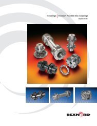
Couplings - Renold plc
Couplings - Renold plc
Couplings - Renold plc

Create successful ePaper yourself
Turn your PDF publications into a flip-book with our unique Google optimized e-Paper software.
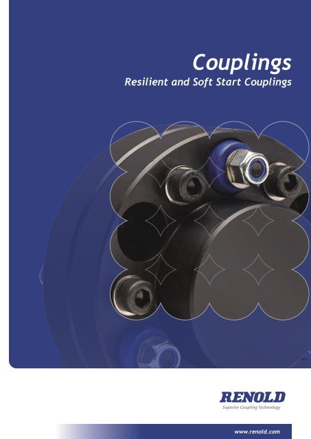
<strong>Couplings</strong><br />
Resilient and Soft Start <strong>Couplings</strong><br />
www.renold.com
www.renold.com
Contents<br />
Page No<br />
<strong>Renold</strong> Gears 02<br />
<strong>Renold</strong> <strong>Couplings</strong> 03<br />
Typical Applications 04<br />
The <strong>Renold</strong> Collection 06<br />
Coupling Comparison Chart 08<br />
Coupling Selection Guide 10<br />
Load Classification by Application 12<br />
Service Factors and Selection 13<br />
Keyway and Keyway Dimensions 14<br />
Taper Bushes 15<br />
Spiderflex 16<br />
Spiderjaw and Spiderwrap 19<br />
Pinflex 22<br />
Crownpin 27<br />
Tyreflex 30<br />
Discflex 33<br />
Chainflex 36<br />
Rigid 38<br />
Gearflex 39<br />
<strong>Renold</strong>flex 53<br />
Hydrastart 58<br />
Terms and Conditions 70<br />
<strong>Renold</strong> Chain inside back cover<br />
Page 01
Strength<br />
Strength through Service<br />
through Service<br />
<strong>Renold</strong> Gears has been manufacturing high quality, high specification gear units for over<br />
<strong>Renold</strong> Gears has been manufacturing high quality, high specification gear units for over<br />
<strong>Renold</strong> 100 years Gears and has hasbeen always manufacturing been at the leading high quality, edge of high gear specification technologygear withunits innovative for over<br />
100 years and has always been at the leading edge of gear technology with innovative<br />
100 products yearsand and power has always transmission been at solutions. the leading edge of gear technology with innovative<br />
products and power transmission solutions.<br />
products and power transmission solutions.<br />
Interchangeability<br />
Interchangeability<br />
Interchangeability<br />
Many of the products from<br />
Many of the products from<br />
Many <strong>Renold</strong>of Gears the products are dimensionally from<br />
<strong>Renold</strong> Gears are dimensionally<br />
<strong>Renold</strong> interchangeable Gears arewith dimensionally other<br />
interchangeable with other<br />
interchangeable manufacturers gear withunits, other<br />
manufacturers gear units,<br />
manufacturers allowing a trouble gear free units,<br />
allowing a trouble free<br />
allowing replacement a trouble of gearboxes, free<br />
replacement of gearboxes,<br />
replacement in most casesof upgrading gearboxes, the<br />
in most cases upgrading the<br />
in capacity most cases through upgrading state of the<br />
capacity through state of the<br />
capacity art technology through and state materials. of the<br />
art technology and materials.<br />
art technology and materials.<br />
Custom<br />
Custom<br />
Custom<br />
Made<br />
Made<br />
Made<br />
<strong>Renold</strong> Gears is unique in it’s<br />
<strong>Renold</strong> Gears is unique in it’s<br />
<strong>Renold</strong> ability to Gears offeriscustom uniquemade in it’s<br />
ability to offer custom made<br />
ability products to designed offer custom to meet made<br />
products designed to meet<br />
products customers designed exactingto<br />
meet<br />
customers exacting<br />
customers requirements exacting without<br />
requirements without<br />
requirements compromise on without availability and<br />
compromise on availability and<br />
compromise cost. From complete on availability package and<br />
cost. From complete package<br />
cost. solutions Fromtocomplete individual package precision<br />
solutions to individual precision<br />
solutions replacement to individual gears, all can precision be<br />
replacement gears, all can be<br />
replacement tailor made togears, meetall specific can be<br />
tailor made to meet specific<br />
tailor applicational made torequirements. meet specific<br />
applicational requirements.<br />
applicational requirements.<br />
Available<br />
Available<br />
Available<br />
The most popular ranges of<br />
The most popular ranges of<br />
The gearboxes most popular are available ranges from of<br />
gearboxes are available from<br />
gearboxes local distribution are available stock, from backed<br />
local distribution stock, backed<br />
local up bydistribution extensive stocks stock, from backed our<br />
up by extensive stocks from our<br />
up manufacturing by extensiveplant stocksinfrom the UK. our<br />
manufacturing plant in the UK.<br />
manufacturing plant in the UK.<br />
Superior Gear & Coupling Technology<br />
Superior Gear & Coupling Technology<br />
Superior Gear & Coupling Technology<br />
www.renold.com<br />
www.renold.com<br />
www.renold.com
<strong>Renold</strong> Clutches and <strong>Couplings</strong>,<br />
Cardiff, Wales<br />
In 1991 the company moved to a purposebuilt<br />
factory in Wentloog, Cardiff, in<br />
which state-of-the-art machining and<br />
inspection facilities are to be found,<br />
all supporting a high level of personal<br />
customer care.<br />
Service Excellence and Care<br />
<strong>Renold</strong> offers a unique level of service<br />
excellence and customer care. Our<br />
experienced applications engineers will<br />
select the optimum solution, with the aid of<br />
the latest computer and design technology.<br />
Specialist Solutions and Innovations<br />
<strong>Renold</strong> is recognised throughout the<br />
industry for its capability to create<br />
specific solutions to customers unique<br />
requirements. International companies and<br />
industries, from steel to food processing<br />
to escalators to textile machinery, have<br />
chosen <strong>Renold</strong> to solve their problems.<br />
Leading edge technology<br />
<strong>Renold</strong> provides practical cost effective<br />
solutions with a commitment to value<br />
through quality. This is achieved by the<br />
continuous investment in people, process<br />
technology and manufacturing.<br />
Consistent Reliability<br />
<strong>Renold</strong>’s 100 years of experience in the<br />
design and manufacturing of power<br />
<strong>Renold</strong> Hi-Tec <strong>Couplings</strong>,<br />
Halifax, England<br />
The Halifax factory (formally Holset<br />
Engineering Ltd.) became a member of<br />
<strong>Renold</strong> <strong>plc</strong> in 1996. The operation also<br />
includes the latest machining and tooling<br />
technology with integrated cellular<br />
manufacturing and complete testing and<br />
balancing capabilities.<br />
transmission products to the highest<br />
specifications, with proven performance in<br />
diverse industries world-wide, underwrites<br />
the guaranteed quality and the assurance of<br />
reliability.<br />
<strong>Renold</strong> Clutches & <strong>Couplings</strong> is BS EN ISO<br />
9001:2000 approved. All products are<br />
designed and manufactured to this Quality<br />
Assurance System.<br />
Page 03<br />
<strong>Renold</strong> <strong>Couplings</strong><br />
<strong>Renold</strong> have been<br />
manufacturing flexible<br />
and rigid couplings, sprag<br />
and air clutches for over<br />
50 years. The <strong>Renold</strong><br />
<strong>Couplings</strong> factories are<br />
based in three global<br />
locations - Cardiff, Wales;<br />
Halifax, England and<br />
Westfield, New York, USA.<br />
<strong>Renold</strong> Ajax,<br />
Westfield, New York, USA.<br />
The company designs and manufactures<br />
custom gear spindles and gear couplings for<br />
the primary metals industry.<br />
Testing<br />
Although each of our factories<br />
manufacturing and testing demands<br />
vary, the following capabilities are available<br />
if the application demands it:<br />
• Full scale radial and axial stiffness<br />
measurement.<br />
• Torsional vibration analysis.<br />
• Misalignment testing of couplings up to<br />
2 metres diameter.<br />
• Measurements of torsional stiffness up to<br />
220 KNM.<br />
• Static and dynamic balancing capabilities.<br />
• Noise attenuation testing.<br />
• Transient and finite element analysis.<br />
The organisation stretches worldwide: • Over 20 National Sales Companies • More than 70 Overseas Distributors<br />
Offering the comprehensive range of power transmission products directly or through local distributor networks<br />
www.renold.com
Page 04<br />
Typical Applications<br />
Resilient and Soft Start <strong>Couplings</strong><br />
Hydrastart<br />
A fluid coupling suitable for soft starting high inertia<br />
machinery with reduced current demand, controlled<br />
acceleration and torque with drive overload protection.<br />
• Conveyors • Rotary Kilns<br />
• Ball Mills • Fans<br />
• Centrifuges<br />
Pinflex<br />
A robust general purpose pin/buffer coupling, providing<br />
reliable fail safe transmission of torque and misalignment<br />
capability.<br />
• Pumps<br />
• Compressors<br />
• Conveyors<br />
Crown Pin<br />
An established pin/buffer coupling offering extended power<br />
capacity where the demand for long life and simplicity<br />
of construction make it suitable for working in arduous<br />
conditions.<br />
• Conveyors • Washers<br />
• Pumps • Screens<br />
• Cranes • General Industrial Applications<br />
Spider <strong>Couplings</strong><br />
Relatively low power but highly flexible coupling with<br />
halfbodies in either cast iron or bronze, making suitable for<br />
use in the food or chemical/pharmaceutical industries.<br />
• Pumps<br />
• Mixers<br />
• Lube Systems<br />
Gearflex<br />
Heavy duty all metal couplings giving maximum power<br />
capacity within minimum space envelope and excellent<br />
misalignment capacity.<br />
• Steelworks<br />
• Quarries<br />
• Mining
Discflex<br />
Page 05<br />
Typical Applications<br />
A general purpose, fail safe, torsionally flexible coupling<br />
offering the option of either urethane or reinforced rubber<br />
disc.<br />
• Pumps • Compressors<br />
• Conveyors • Mixers<br />
Spiderflex<br />
A medium powered, torsionally flexible coupling, combining<br />
shock absorbing and misalignment. Used in the widest range<br />
of industries and applications.<br />
Tyreflex<br />
A range of highly flexible couplings offering excellent<br />
misalignment capacity and suitable to absorb both shock<br />
loads and vibrations.<br />
• Pumps • Compressors<br />
• Diesel engines • Roller tables<br />
<strong>Renold</strong>flex<br />
<strong>Renold</strong>flex is a torsionally rigid coupling (TRC) that utilises<br />
a stainless steel spring disc pack to provide a positive<br />
“backlash free” drive.<br />
• Pumps • Compressors<br />
• Packaging machines • High temp boiler feeds<br />
• Wind Turbines • Petrochemical pump installations<br />
• High speed general installations<br />
Coupling customisation<br />
<strong>Renold</strong> is able to offer a full customisation service across its<br />
complete range of coupling and clutch products.<br />
www.renold.com
Page 06<br />
The Collection<br />
Page 16<br />
Spiderflex Coupling<br />
Max power / 100 rpm (kW) 33 kW<br />
Max weight 63 kg<br />
Max shaft size 115 mm<br />
Max speed (rpm) 7,700 rpm<br />
Max outer diameter 275 mm<br />
Max torque (Nm) 3,150 Nm<br />
www.renold.com<br />
Tyreflex Coupling<br />
Pinflex Coupling<br />
Max power / 100 rpm (kW) 340 kW<br />
Max weight 423 kg<br />
Max shaft size 260 mm<br />
Max speed (rpm) 6,800 rpm<br />
Max outer diameter 490 mm<br />
Max torque (Nm) 32,500 Nm<br />
www.renold.com<br />
SpiderJaw Coupling<br />
Max power / 100 rpm (kW) 45 kW<br />
Max weight 84 kg<br />
Max shaft size 115 mm<br />
Max speed (rpm) 31,000 rpm<br />
Max outer diameter 305 mm<br />
Max torque (Nm) 4,308 Nm<br />
Page 19<br />
www.renold.com<br />
Page 22 Page 27<br />
Max power / 100 rpm (kW) 66 kW<br />
Max weight 49 kg<br />
Max shaft size 150 mm<br />
Max speed (rpm) 4,500 rpm<br />
Max outer diameter 470 mm<br />
Max torque (Nm) 6,270 Nm<br />
www.renold.com<br />
Discflex Coupling<br />
Max power / 100 rpm (kW) 45 kW<br />
Max weight 67 kg<br />
Max shaft size 110 mm<br />
Max speed (rpm) 2,900 rpm<br />
Max outer diameter 324 mm<br />
Max torque (Nm) 4,298 Nm<br />
www.renold.com<br />
Crownpin Coupling<br />
Max power / 100 rpm (kW) 2,607 kW<br />
Max weight 2,250 kg<br />
Max shaft size 300 mm<br />
Max speed (rpm) 6,210 rpm<br />
Max outer diameter 1,220 mm<br />
Max torque (Nm) 249,400 Nm<br />
www.renold.com<br />
Page 30 Page 33 Page 36<br />
Resilient and Soft Start <strong>Couplings</strong><br />
Page 19<br />
SpiderWrap Coupling<br />
Max power / 100 rpm (kW) 45 kW<br />
Max weight 84 kg<br />
Max shaft size 115 mm<br />
Max speed (rpm) 9,000 rpm<br />
Max outer diameter 323 mm<br />
Max torque (Nm) 4,308 Nm<br />
www.renold.com<br />
Chainflex Coupling<br />
Max power / 100 rpm (kW) 90 kW<br />
Max weight 85 kg<br />
Max shaft size 140 mm<br />
Max speed (rpm) 3,500 rpm<br />
Max outer diameter 357 mm<br />
Max torque (Nm) 8,595 Nm<br />
www.renold.com
A Series Gear Coupling<br />
Max power / 100 rpm (kW) 1,640 kW<br />
Max weight 443 kg<br />
Max shaft size 260 mm<br />
Max speed (rpm) 7,100 rpm<br />
Max outer diameter 527 mm<br />
Max torque (Nm) 156,620 Nm<br />
www.renold.com<br />
Rigid Coupling<br />
Max power / 100 rpm (kW) 1,640 kW<br />
Max weight 501 kg<br />
Max shaft size 290 mm<br />
Max speed (rpm) 7,100 rpm<br />
Max outer diameter 527 mm<br />
Max torque (Nm) 156,620 Nm<br />
www.renold.com<br />
Page 38 Page 53<br />
Page 42 Page 46<br />
Hydrastart Coupling<br />
Max power / 100 rpm (kW) 39.1 kW<br />
Max weight 207 kg<br />
Max shaft size 127 mm<br />
Max speed (rpm) 3,500 rpm<br />
Max outer diameter 751 mm<br />
Max torque (Nm) N/A<br />
www.renold.com<br />
D Series Gear Coupling<br />
Page 58 Page 70<br />
Page 07<br />
The Collection<br />
<strong>Renold</strong>flex<br />
Max power / 100 rpm (kW) 2,209 kW<br />
Max weight 374 kg<br />
Max shaft size 197 mm<br />
Max speed (rpm) N/A<br />
Max outer diameter 518 mm<br />
Max torque (Nm) 211,000 Nm<br />
www.renold.com<br />
Max power / 100 rpm (kW) 482 kW<br />
Max weight N/A<br />
Max shaft size 180 mm<br />
Max speed (rpm) 1,2000 rpm<br />
Max outer diameter 345 mm<br />
Max torque (Nm) 46,000 Nm<br />
www.renold.com<br />
Hydrastart Drop-in Coupling<br />
Max power / 100 rpm (kW) 39.1 kW<br />
Max weight N/A<br />
Max shaft size 110 mm<br />
Max speed (rpm) 2,500 rpm<br />
Max outer diameter 751 mm<br />
Max torque (Nm) N/A<br />
www.renold.com<br />
Croft MB Gear Coupling<br />
Max power / 100 rpm (kW) 565 kW<br />
Max weight 560 kg<br />
Max shaft size 220 mm<br />
Max speed (rpm) 3,730 rpm<br />
Max outer diameter 930 mm<br />
Max torque (Nm) 54,000 Nm<br />
www.renold.com<br />
www.renold.com
Page 08<br />
Coupling Comparison Chart<br />
Resilient and Soft Start <strong>Couplings</strong><br />
Coupling Type Characteristics Max misalignment capabilities*<br />
Torsionally Flexible Spiderflex (RSC) +1.7 2.5 0.5<br />
SpiderJaw (SC) +0.5 1 0.4<br />
SpiderWrap (SC) +0.5 1 0.4<br />
Pinflex (PF) +/-2 0.25 0.13<br />
Crownpin (CP) +/-1.5 0.15 0.18<br />
Tyreflex (TY) +/-6 4 4.8<br />
Discflex (D) 5.3 1 0.5<br />
Metal To Metal Chainflex (CF) 4.6 1 0.5<br />
Gearflex A Series<br />
Please<br />
consult<br />
<strong>Renold</strong><br />
1.5 7.8<br />
Gearflex HD series 22.1 0.75 10.6<br />
Gearflex NTS Series 3 1.5 0.48<br />
Gearflex D Series<br />
Please<br />
consult<br />
<strong>Renold</strong><br />
6 25.2<br />
Rigid Rigid (RC) N/A N/A N/A<br />
Torsionally Rigid <strong>Renold</strong>flex +/-2.6 2<br />
Fluid Hydrastart<br />
Shockloading<br />
absorbption<br />
* Misalignment figures are the MAXIMUM for the each coupling range.<br />
Vibration/<br />
Damping<br />
Maintenance<br />
free<br />
Backlash free<br />
Soft start<br />
Spacer version<br />
Axial (mm)<br />
Please<br />
consult<br />
<strong>Renold</strong><br />
Angular<br />
(degrees)<br />
Please<br />
consult<br />
<strong>Renold</strong><br />
Offset<br />
(parallel) (mm)<br />
Please<br />
consult<br />
<strong>Renold</strong><br />
Please<br />
consult<br />
<strong>Renold</strong>
Nominal torque range (Nm) Max shaft Taper Speed range<br />
Light duty Medium duty<br />
diameter lock (mm)<br />
Heavy duty<br />
100<br />
1,000<br />
10,000<br />
100,000<br />
1,000,000<br />
Bore<br />
and key<br />
(mm)<br />
32 – 3,150Nm 115 90 Up to 7,700rpm<br />
0.4 – 4,308Nm 115 75 Up to 31,000rpm<br />
21.1 – 4,308Nm 115 75 Up to 9,000rpm<br />
194 – 32,500Nm 260 125 Up to 6,800rpm<br />
23,490 – 249,400Nm 300 100 Up to 6,210rpm<br />
25 – 6,270Nm 150 125 Up to 4,500rpm<br />
72 – 4,298Nm 110 90 Up to 2,900rpm<br />
52 – 8,595Nm 140 60 Up to 3,500rpm<br />
1,432 – 156,620Nm 260 Up to 7,100rpm<br />
185,120 – 4,747,000Nm 840 Up to 2,000rpm<br />
668 – 120,000Nm 190 Up to 10,000rpm<br />
294 – 210,938Nm 197 Please consult <strong>Renold</strong><br />
1,432 – 156,620Nm 290 125 Up to 12,000rpm<br />
18 – 46,000Nm 180 Up to 12,000rpm<br />
Please consult <strong>Renold</strong> 150 Up to 3,500rpm<br />
10,000,000<br />
Page 09<br />
Coupling Comparison Chart<br />
1,000 rpm<br />
10,000 rpm<br />
100,000 rpm<br />
www.renold.com
Page 10<br />
Coupling Selection Guide<br />
DRIVE POWER<br />
LOW: Up to 10kW<br />
No<br />
MEDIUM: Up to 50kW<br />
No<br />
Resilient and Soft Start <strong>Couplings</strong><br />
High speed<br />
Torsionally<br />
Yes Yes/No<br />
Yes<br />
(motor speeds)<br />
flexible<br />
High speed<br />
Torsionally<br />
Yes Yes/No<br />
Yes<br />
(motor speeds)<br />
flexible<br />
Spider<br />
Discflex<br />
Pinflex<br />
Spiderflex<br />
Tyreflex<br />
Crownpin<br />
Gearflex<br />
Chainflex<br />
<strong>Renold</strong>flex<br />
Spider<br />
Discflex<br />
Pinflex<br />
Spiderflex<br />
Tyreflex<br />
Crownpin<br />
Gearflex<br />
Chainflex<br />
<strong>Renold</strong>flex<br />
HIGH: Above 50kW High speed<br />
Torsionally<br />
Yes Yes/No<br />
Yes<br />
Gearflex<br />
(motor speeds)<br />
flexible<br />
Chainflex<br />
No<br />
No<br />
No<br />
Gearflex<br />
Chainflex
At installation all couplings should be aligned as near to Ø<br />
perfect as possible.<br />
1. Angular<br />
Angular misalignment is present when the shaft axes are<br />
inclined one to the other. Its magnitude can be measured at the<br />
coupling faces.<br />
2. Parallel Offset<br />
Axial misalignment is present when the axes of the driving and<br />
driven shafts are parallel but laterally displaced.<br />
3. End float (axial)<br />
End float is the ability to accommodate a relative axial<br />
displacement of the connected shafts; achieved by sliding<br />
members or flexing of resilient components.<br />
4. Torsional flexibility<br />
Torsional flexibility is a design feature necessary to permit shock<br />
and impulsive loadings to be suitably dampened. It is achieved<br />
by the provision of a flexible medium such as rubber, springs,<br />
etc., between the two halves of the coupling.<br />
Selection<br />
In order to select the correct type and size of coupling, the<br />
following basic information should be known:<br />
Power to be transmitted<br />
(a) Normal.<br />
(b) Maximum.<br />
(c) Whether continuous or intermittent.<br />
Ø<br />
Ø<br />
Angular<br />
Characteristics of the drive<br />
(a) Type of prime mover and associated equipment.<br />
(b) Degree of impulsiveness of driven load.<br />
O<br />
O<br />
Parallel offset<br />
Page 11<br />
Coupling Selection Guide<br />
Flexible <strong>Couplings</strong> should be used ƒ to accommodate any combination of misalignment conditions<br />
described below.<br />
ƒ<br />
Ø<br />
Ø<br />
O<br />
Ø<br />
O<br />
End float<br />
ƒ<br />
Torsional flexibility<br />
Speed in revolutions per minute<br />
(a) At which normal power is transmitted.<br />
(b) At which maximum power is transmitted.<br />
(c) Maximum speed.<br />
Dimensions of shafts to be connected<br />
(a) Actual diameter.<br />
(b) Length of shaft extension.<br />
(c) Full keyway particulars.<br />
Selection<br />
When the input drive is not steady (i.e. not from an electric<br />
motor), and/or the driven load is impulsive, the actual power is<br />
multiplied by a Service Factor from the Table 2 (page 13).<br />
Selection Procedure<br />
1. Nominal power in kW to be transmitted = K.<br />
2. Select appropriate load classification from Table 1, denoted<br />
as either S, M or H.<br />
3. From Table 2, establish Service Factor(s) to be applied, taking<br />
into account hours of operation/day and prime mover = fD.<br />
4. From Table 3 select factor for the required frequency of<br />
starts/hr = fS.<br />
5. Selection Power Ks = K x fD x fS<br />
ƒ<br />
6. Equivalent power at 100 RPM = Ks x 100<br />
RPM<br />
7. Check that coupling selected will accept the required shaft<br />
diameters. Should shaft diameter exceed maximum permissible,<br />
then re-select using next larger size of coupling.<br />
Ø<br />
Ø<br />
www.renold.com
Page 12<br />
Load Classification by Application<br />
Table 1<br />
Agitators<br />
Pure liquids S<br />
Liquids and solids M<br />
Liquids - variable density<br />
Blowers<br />
M<br />
Centrifugal S<br />
Lobe M<br />
Vane<br />
Brewing and distilling<br />
S<br />
Bottling machinery S<br />
Brew kettles - continuous duty S<br />
Cookers - continuous duty S<br />
Mash tubs - continuous duty S<br />
Scale hopper - frequent starts M<br />
Can filling machines S<br />
Cane knives (1) M<br />
Car dumpers H<br />
Car pullers M<br />
Clarifiers S<br />
Classifiers<br />
Clay working machinery<br />
M<br />
Brick press H<br />
Briquette machine H<br />
Clay working machinery M<br />
Pug mill<br />
Compressors<br />
M<br />
Centrifugal S<br />
Lobe M<br />
Reciprocating - multi-cylinder M<br />
Reciprocating - single cylinder<br />
Conveyors - uniformly loaded or fed<br />
H<br />
Apron S<br />
Assembly S<br />
Belt S<br />
Bucket S<br />
Chain S<br />
Flight S<br />
Oven S<br />
Screw<br />
Conveyors - heavy duty<br />
not uniformly fed<br />
S<br />
Apron M<br />
Assembly M<br />
Belt M<br />
Bucket M<br />
Chain M<br />
Flight M<br />
Live roll *<br />
Oven M<br />
Reciprocating H<br />
Screw M<br />
Shaker<br />
Crane Drives - not dry dock<br />
H<br />
Main hoists S<br />
Bridge travel *<br />
Trolley travel<br />
Crushers<br />
*<br />
Ore H<br />
Stone H<br />
Sugar (1)<br />
Dredges<br />
M<br />
Cable reels M<br />
Conveyors M<br />
Cutter head drives H<br />
Jig drives H<br />
Manoeuvring winches M<br />
Pumps M<br />
Screen drive H<br />
Stackers<br />
Utility winches<br />
M<br />
M<br />
Key<br />
S = Steady<br />
M = Medium Impulsive<br />
H = Highly Impulsive<br />
* = Refer to <strong>Renold</strong><br />
Resilient and Soft Start <strong>Couplings</strong><br />
Dry dock cranes<br />
Main hoist (2)<br />
Auxiliary hoist (2)<br />
Boom, luffing (2)<br />
Rotating, swing or slew (3)<br />
Tracking, drive wheels (4)<br />
Elevators<br />
Bucket - uniform load S<br />
Bucket - heavy load M<br />
Bucket - continuous S<br />
Centrifugal discharge S<br />
Escalators S<br />
Freight M<br />
Gravity discharge S<br />
Man lifts *<br />
Passenger *<br />
Extruders (plastic)<br />
Film S<br />
Sheet S<br />
Coating S<br />
Rods S<br />
Tubing S<br />
Blow moulders M<br />
Pre-plasticiers M<br />
Fans<br />
Centrifugal S<br />
Cooling towers<br />
Induced draft *<br />
Forced draft *<br />
Induced draft M<br />
Large, mine etc. M<br />
Large, industrial M<br />
Light, small diameter S<br />
Feeders<br />
Apron M<br />
Belt M<br />
Disc S<br />
Reciprocating H<br />
Screw M<br />
Food industry<br />
Beef slicer M<br />
Cereal cooker S<br />
Dough mixer M<br />
Meat grinder M<br />
Generators - not welding S<br />
Hammer mills H<br />
Hoists<br />
Heavy duty H<br />
Medium duty M<br />
Skip hoist M<br />
Laundry<br />
Washers - reversing M<br />
Tumblers M<br />
Line shafts<br />
Driving processing equipment M<br />
Light S<br />
Other line shafts S<br />
Lumber industry<br />
Barkers, hydraulic, mechanical M<br />
Burner conveyor M<br />
Chain saw and drag saw H<br />
Chain transfer H<br />
Craneway transfer H<br />
De-barking drum H<br />
Edger feed M<br />
Gang feed M<br />
Green chain M<br />
Live rolls H<br />
Log deck H<br />
Log haul - incline H<br />
Log haul - well type H<br />
Log turning device H<br />
Main log conveyor H<br />
Off bearing rolls M<br />
(1) = Select on 24 hours per day service factor only.<br />
(2) = Use service factor of 1.00 for any duration of service.<br />
(3) = Use service factor of 1.25 for any duration of service.<br />
(4) = Use service factor of 1.50 for any duration of service.<br />
Planer feed chains M<br />
Planer floor chains M<br />
Planer tilting hoist M<br />
Re-saw merry-go-round conveyor M<br />
Roll cases H<br />
Slab conveyor H<br />
Small waste conveyor-belt S<br />
Small waste conveyor-chain M<br />
Sorting table M<br />
Tipple hoist conveyor M<br />
Tipple hoist drive M<br />
Transfer conveyors M<br />
Transfer rolls M<br />
Tray drive M<br />
Trimmer feed M<br />
Waste conveyor M<br />
Machine tools<br />
Bending roll M<br />
Punch press - gear driven H<br />
Notching press - belt drive *<br />
Plate planners H<br />
Tapping machine H<br />
Other machine tools<br />
Main drives M<br />
Auxiliary drives S<br />
Metal mills<br />
Drawn bench carriage and<br />
main drive M<br />
Pinch, dryer and scrubber<br />
rolls, reversing *<br />
Slitters M<br />
Table conveyors nonreversing<br />
group drives M<br />
Individual drives H<br />
Reversing *<br />
Wire drawing and flattening machine M<br />
Wire winding machine M<br />
Mills, rotary type<br />
Ball (1) M<br />
Cement kilns (1) M<br />
Dryers and coolers (1) M<br />
Kilns other than cement M<br />
Pebble (1) M<br />
Rod, plain & wedge bar (1) M<br />
Tumbling barrels H<br />
Mixers<br />
Concrete mixers continuous M<br />
Concrete mixers intermittent M<br />
Constant density S<br />
Variable density M<br />
Oil industry<br />
Chillers M<br />
Oil well pumping *<br />
Paraffin filter press M<br />
Rotary kilns M<br />
Paper mills<br />
Agitators (mixers) M<br />
Barker - auxiliaries hydraulic M<br />
Barker - mechanical H<br />
Barking drum H<br />
Beater and pulper M<br />
Bleacher S<br />
Calenders M<br />
Calenders - super H<br />
Converting machine except<br />
cutters, platers M<br />
Conveyors S<br />
Couch M<br />
Cutters, platers H<br />
Cylinders M<br />
Dryers M<br />
Fell stretcher M<br />
Fell whipper H<br />
Jordans M<br />
Log haul H<br />
Presses M<br />
Pulp machine reel M<br />
Stock chest M<br />
Suction roll M<br />
Washers and thickeners M<br />
Winders M<br />
Printing presses *<br />
Pullers<br />
Barge haul H<br />
Pumps<br />
Centrifugal S<br />
Proportioning M<br />
Reciprocating<br />
single acting: 3 or more cylinders M<br />
double acting: 2 or more cylinders M<br />
single acting: 1 or 2 cylinders *<br />
double acting: single cylinder *<br />
Rotary - gear type S<br />
Rotary - lobe, vane S<br />
Rubber and plastics industries<br />
Crackers (1) H<br />
Laboratory equipment M<br />
Mixed mills (1) H<br />
Refiners (1) M<br />
Rubber calenders (1) M<br />
Rubber mill, 2 on line (1) M<br />
Rubber mill, 3 on line (1) S<br />
Sheeter (1) M<br />
Tyre building machines *<br />
Tyre and tube press openers *<br />
Tubers and strainers (1) M<br />
Warming mills (1) M<br />
Sand muller M<br />
Screens<br />
Air washing S<br />
Rotary, stone or gravel M<br />
Travelling water intake S<br />
Sewage disposal equipment<br />
Bar screens S<br />
Chemical feeders S<br />
Collectors S<br />
Dewatering screws M<br />
Scum breakers M<br />
Slow or rapid mixers M<br />
Thickeners M<br />
Vacuum filters M<br />
Slab pushers M<br />
Steering gear *<br />
Stokers S<br />
Sugar industry<br />
Cane knives (1) M<br />
Crushers (1) M<br />
Mills (1) M<br />
Textile industry<br />
Batchers M<br />
Calenders M<br />
Cards M<br />
Dry cans M<br />
Dryers M<br />
Dyeing machinery M<br />
Looms M<br />
Mangles M<br />
Nappers M<br />
Pads M<br />
Range drives *<br />
Slashers M<br />
Soapers M<br />
Spinners M<br />
Tenter frames M<br />
Washers M<br />
Winders M<br />
Windlass *<br />
Note<br />
Machinery characteristics and service factors listed in this catalogue are<br />
a guide only. Some applications (e.g. constant power) may require special<br />
considerations. Please consult <strong>Renold</strong>.
Table 2 Service Factor (fD)<br />
Example of Selection<br />
Coupling is required to transmit 7.5kW at 1440 RPM to connect<br />
an electric motor to a gear box driving a chain conveyor running<br />
for 18 hours/day and starting 15 times/hour. Shaft diameters<br />
/55mm respectively.<br />
K = 7.5kW<br />
Prime mover<br />
From Table 1 Load Classification = M (medium impulsive)<br />
From Table 2 Service Factor fD = 1.5<br />
From Table 3 fS = 1.2<br />
Therefore selection kW is:-<br />
Ks = K x fD x fS<br />
= 7.5 x 1.5 x 1.2<br />
= 13.5 kW<br />
Equivalent power at 100 RPM = Ks x 100<br />
RPM<br />
= 13.5 x 100<br />
1440<br />
= 0.9375kW @ 100RPM<br />
From page 17 selection is RSC110 (644911)<br />
(maximum bore 55 mm).<br />
Driven machinery characteristics<br />
Key Stress<br />
1. Permissible key stress = 70N/mm 2<br />
2. Nominal torque TKM = K x 9550 / RPM Nm<br />
3. Force at key F = TKM /r<br />
4. Shaft Rad r. metres<br />
5. Key area A = J x HUB length mm<br />
(Obtain from relevant catalogue page).<br />
6. Key stress fk = F/A N/mm 2<br />
7. If resultant stress is less than 70 N/mm 2 key stress is<br />
acceptable.<br />
If resultant fk is greater than 70, consider either two keyways<br />
or extending hub length.<br />
8. Example:<br />
TKM = 7.5 x 9550/1440 = 49.7Nm<br />
r = 55/2 = 27.5mm ÷ 1000 = 0.0275m<br />
F = 49.7/0.0275 = 1741N<br />
A = 16 x 45 = 720mm 2<br />
fk = 1741/720 = 2.4M/mm 2<br />
Selection is therefore good.<br />
Page 13<br />
Service Factors and Selection<br />
(Drive input) Duration service Steady load Medium impulsive Highly impulsive<br />
hours/day<br />
Electric, air & hydraulic Intermittent – 3hrs/day max 0.90 1.00 1.50<br />
Motors or steam turbine 3 - 10 1.00 1.25 1.75<br />
(Steady input) over 10 1.25 1.50 2.00<br />
Multi-cylinder I.C. engine Intermittent – 3hrs/day max 1.00 1.25 1.75<br />
(Medium impulsive input) 3 - 10 1.25 1.50 2.00<br />
over 10 1.50 1.75 2.25<br />
Single-cylinder I.C. engine Intermittent - 3hrs/day max 1.25 1.50 2.00<br />
(Highly impulsive input) 3 - 10 1.50 1.75 2.25<br />
over 10 1.75 2.00 2.50<br />
Table 3 Factor for Starts/Hour(fS)<br />
No of starts per hour 0-1 1-30 30-60 60-<br />
!<br />
WARNING<br />
Factor 1,0 1,2 1,3 1,5<br />
It is the responsibility of the system designer<br />
to ensure that the application of the coupling<br />
does not endanger the other constituent<br />
components in the system. Service factors<br />
given are an initial selection guide.<br />
For operation above 80% of the declared maximum coupling<br />
speed it is recommended that the coupling is dynamically<br />
balanced.<br />
!<br />
WARNING<br />
Rotating equipment must be provided with<br />
a suitable guard before operating or injury<br />
may result.<br />
www.renold.com
Page 14<br />
Key and Keyway Dimensions<br />
Metric (mm)<br />
Keyways comply with BS4235: Part 1: 1972<br />
Shaft dia. Key & keyway<br />
Over Incl. J K L<br />
6 8 2 2 1.0<br />
8 10 3 3 1.4<br />
10 12 4 4 1.8<br />
12 17 5 5 2.3<br />
17 22 6 6 2.8<br />
22 30 8 7 3.3<br />
30 38 10 8 3.3<br />
38 44 12 8 3.3<br />
44 50 14 9 3.8<br />
50 58 16 10 4.3<br />
58 65 18 11 4.4<br />
65 75 20 12 4.9<br />
75 85 22 14 5.4<br />
85 95 25 14 5.4<br />
95 110 28 16 6.4<br />
110 130 32 18 7.4<br />
130 150 36 20 8.4<br />
150 170 40 22 9.4<br />
170 200 45 25 10.4<br />
200 230 50 28 11.4<br />
Resilient and Soft Start <strong>Couplings</strong><br />
[ fig 01 ]<br />
L<br />
L<br />
J<br />
Imperial (inches)<br />
J<br />
K<br />
Keyways comply with BS46: Part 1: 1958<br />
Shaft dia. Key & keyway<br />
Over Incl. J K L<br />
0.25 0.05 0.125 0.125 0.060<br />
0.50 0.75 0.187 0.187 0.088<br />
0.75 1.00 0.250 0.250 0.115<br />
1.00 1.25 0.312 0.250 0.090<br />
1.25 1.50 0.375 0.250 0.085<br />
1.50 1.75 0.437 0.312 0.112<br />
1.75 2.00 0.500 0.312 0.108<br />
2.00 2.50 0.625 0.437 0.162<br />
2.50 3.00 0.750 0.500 0.185<br />
3.00 3.50 0.875 0.625 0.245<br />
3.50 4.00 1.000 0.750 0.293<br />
4.00 5.00 1.250 0.875 0.340<br />
5.00 6.00 1.500 1.000 0.384<br />
Keyway dimensions [ fig 01 ]<br />
Parallel keyways are supplied unless customer states otherwise.<br />
K
Metric range<br />
Bush no. Range of bores (mm)<br />
TB 1008 9 10 - 12 14 16 18 19 20 22 24* 25*<br />
TB 1108 9 10 11 12 14 15 16 18 19 20 22 24 25 28*<br />
TB 1210 11 12 14 16 18 19 20 22 24 25 28* 30* 32*<br />
TB 1215 11 12 14 16 18 19 20 22 24 25 28 30 32*<br />
TB 1610 14 16 18 19 20 22 24 25 28 30 32 35 38 40 42<br />
TB 1615 14 16 18 19 20 22 24 25 28 30 32 35 38 40* 42*<br />
Page 15<br />
Taper Bushes<br />
TB 2012 14 16 18 19 20 22 24 25 28 30 32 35 38 40 42 44 45 48 L 50<br />
TB 2017 18 19 20 22 24 25 28 30 32 35 38 40 42 45 48 50*<br />
TB 2517 16 18 19 20 22 24 25 28 30 32 35 38 40 42 45 48 50 55 60<br />
TB 2525 19 20 22 24 25 28 30 32 35 38 40 42 45 48 50 55 60<br />
TB 3020 25 28 30 32 35 38 40 42 45 48 50 55 60 65 70 75<br />
TB 3030 35 38 40 42 45 48 50 55 60 65 70 75<br />
TB 3525 35 38 40 42 45 48 50 55 60 65 70 75 80 85 90 95 100*<br />
TB 3535 35 38 40 42 45 48 50 55 60 65 70 75 80 85 90<br />
TB 4030 40 42 45 48 50 55 60 65 70 75 80 85 90 95 100<br />
TB 4040<br />
TB 4535<br />
40<br />
55<br />
42<br />
60<br />
45<br />
65<br />
48<br />
70<br />
50<br />
75<br />
55<br />
80<br />
60<br />
85<br />
65<br />
90<br />
70<br />
95<br />
75<br />
100<br />
80<br />
105<br />
85<br />
110<br />
90<br />
115<br />
95<br />
120<br />
100<br />
125<br />
J<br />
TB 5050 70 75 80 85 90 95 100 105 110 115 120 125<br />
Imperial range<br />
Bush no. Range of bores (inches)<br />
TB 1008 0.375 0.437 0.50 0.625 0.75 1.00*<br />
TB 1108 0.375 0.50 0.625 0.75 0.875 1.00 1.125*<br />
TB 1210 - 0.50 - 0.625 - 0.75 - - - 1.00 - - 1.25<br />
TB 1215 - 0.50 0.562 0.625 - 0.75 - 0.875 - 1.00 - - 1.125<br />
TB 1610 0.50 - 0.625 - 0.75 - 0.875 - 1.00 - 1.125 1.25 - - - 1.50 1.625<br />
TB 1615<br />
TB 2012<br />
0.50 - 0.625 - 0.75<br />
0.50 0.625 0.75 0.875 1.00<br />
-<br />
-<br />
0.875<br />
1.125<br />
-<br />
-<br />
1.00<br />
1.25<br />
-<br />
-<br />
1.125 1.25 - 1.375 1.437 1.50 K 1.625*<br />
1.375 1.50 1.625 1.75 1.87 2.0<br />
TB 2017 0.75 0.812 0.875 0.937 1.00 - 1.125 - 1.25 - 1.375 1.50 1.625 1.75 1.875 2.00<br />
TB 2517 0.75 0.875 - 1.00 - 1.125 - 1.25 - 1.375 1.437 1.625 1.75 1.875 2.00 2.125 2.25 2.375* 2.50<br />
TB 2525 - - 1.00 - 1.125 - 1.25 - 1.375 - 1.50 1.75 1.875 2.00 2.125 2.25 2.375* 2.50*<br />
TB 3020 1.25 - 1.375 - 1.50 1.625 1.75 1.875 2.00 2.125 2.25 2.50 2.625 2.75 2.875 3.00<br />
TB 3030 - - 1.375 - 1.50 1.625 1.75 1.875 2.00 2.125 2.25 2.50 2.625 2.75 2.875 3.00<br />
TB 3525 1.50 1.625 1.75 1.875 2.00 2.125 2.25 2.375 2.50 2.625 2.75 3.00 3.125 3.25 3.50 3.75* 4.00*<br />
TB 3535 1.50 1.625 1.75 1.875 2.00 2.125 2.25 2.375 2.50 2.625 2.75 3.00 3.125 3.25 3.50<br />
TB 4030 1.75 1.875 2.00 2.125 2.25 2.375 2.50 2.625 2.75 2.875 3.00 3.125 3.25 3.375 3.50<br />
TB 4040 1.75 1.875 2.00 2.125 2.25 2.375 2.50 2.625 2.75 2.875 3.00 3.25 3.375 3.50 3.625 3.75* 4.00<br />
TB 4535 2.25 2.375 2.50 2.625 2.75 2.875 3.00 3.125 3.25 3.375 3.50 3.75 4.00 4.25 4.50 4.75 5.00*<br />
TB 5050 2.75 2.875 3.00 3.25 3.375 3.50 3.75 4.00 4.25 4.50 5.00<br />
page 8 A/W’s<br />
*Shallow key Depth. N.B.When ordering specify both bush number and bore size required.<br />
www.renold.com
Page 16<br />
Spiderflex<br />
A medium power torsionally flexible coupling combining shock absorbing and misalignment<br />
capacity, used in the widest range of industries and applications.<br />
Coupling capacity<br />
• Maximum power @ 100rpm: 33kW<br />
• Maximum torque: 3150Nm<br />
Features and benefits<br />
• Torsionally flexible – shock<br />
absorbing, extending machine life<br />
• Maintenance free – minimum number<br />
of wearing parts<br />
• Misalignment capabilities allowing<br />
flexibility in installation<br />
• Cost effective – offering a low cost<br />
product with high quality design<br />
• Dimensionally similar to other spider<br />
couplings – interchangeable<br />
• Optional fire retardant anti-static<br />
elements for use in flameproof<br />
environment<br />
Resilient and Soft Start <strong>Couplings</strong><br />
• Taper bush bores available for ease<br />
of maintenance<br />
• Compact design – small, with high<br />
torque capacity<br />
Standard range comprises<br />
• Shaft to shaft<br />
• Flywheel to shaft<br />
• Taper bush or parallel bore<br />
Applications<br />
• Bulk handling<br />
• Compressors<br />
• Generator sets<br />
• Metal manufacture<br />
• Pumps<br />
• General industrial applications<br />
Can be certified for use in potentially explosive atmospheres<br />
containing gas or dust, according to ATEX directive 94/9/EC.<br />
The couplings are classified for equipment group II, categories 2 and 3.<br />
Contact <strong>Renold</strong> for further details.<br />
General details<br />
• Cast iron half bodies grade G220<br />
• Standard element shore harness A90<br />
Temp range -30 to +100ºC<br />
• FRAS element shore harness A78<br />
Temp range -30 to +95ºC
H1<br />
DD BB<br />
DD BB<br />
DD<br />
BB<br />
E<br />
C1<br />
H2 H1<br />
C2<br />
H2 H1<br />
C2<br />
G<br />
Assembled length<br />
Type B Type F Type H<br />
Assembled overall length<br />
F<br />
L<br />
Page 17<br />
Spiderflex<br />
Coupling Power Torque Speed Type B Type F & H Max. misalignment End<br />
size /100rpm nominal max Bore dia Bush Bore Offset Angular float<br />
kW Nm rpm Max Min size Max Min mm deg mm<br />
RSC70 # # # 0.33 32 7700 32 0 TB1008 25 9 0.3 0.5 +.2<br />
RSC90 # # # 0.84 80 6300 42 0 TB1108 28 9 0.3 0.5 +.5<br />
RSC110 # # # 1.68 160 5000 55 0 TB1610 42 14 0.3 1 +.6<br />
RSC130 # # # 3.30 315 4100 60 0 TB1610 42 14 0.4 1 +.8<br />
RSC150 # # # 6.28 600 3600 70 0 TB2012 50 14 0.4 1.5 +.9<br />
RSC180 # # # 9.95 950 3000 80 0 TB2517 60 16 0.4 1.5 +1.1<br />
RSC230 # # # 21 2000 2600 100 48 TB3020 75 25 0.5 2 +1.3<br />
RSC280 # # # 33 3150 2200 115 60 TB3525 90 35 0.5 2.5 +1.7<br />
Coupling<br />
Dimensions Assembled overall length L<br />
size B C1 C2 D E F G H1 H2 With half body combinations:<br />
mm mm mm mm mm mm mm mm mm<br />
BB FF, FH, HH FB, HB<br />
RSC70 # # # 61 23.5 23.5 69 31 18 25 20 20.0 65 65 65<br />
RSC90 # # # 70 30.0 23.5 85 32 22.5 30.5 26 19.5 83 70 77<br />
RSC110 # # # 100 45.0 26.5 112 45 29 45 37 18.5 119 82 101<br />
RSC130 # # # 105 55.5 26.5 139 50 36 53 47 18.0 147 89 118<br />
RSC150 # # # 115 60.0 33.5 150 62 40 60 50 23.5 160 107 134<br />
RSC180 # # # 125 70.0 46.4 180 77 49 73 73 34.5 189 142 166<br />
RSC230 # # # 155 90.0 52.5 225 99 59.5 85.5 85.5 39.5 240 164 202<br />
RSC280 # # # 206 105.5 66.5 275 119 74.5 105.5 105.5 51.0 285 207 246<br />
1. At speeds exceeding allowable maximum speed, consult <strong>Renold</strong>.<br />
2. Both moment of inertia and coupling weight have been calculated assuming fitting of taper bush of medium bore size.<br />
3. For information on torsional stiffness, consult <strong>Renold</strong>.<br />
www.renold.com
Page 18<br />
Spiderflex<br />
Ordering code<br />
Spiderflex<br />
Size<br />
Half body type<br />
B – Plain bore<br />
F – Taper bush<br />
H – Taper bush<br />
Coupling<br />
Coupling Coupling Inertia WR2<br />
size Mass Type B Type F&H<br />
Kg KG m2 KG m2 RSC70 1.00 0.00078 0.00085<br />
RSC90 1.17 0.00108 0.00115<br />
RSC110 5.00 0.00344 0.00400<br />
RSC130 5.46 0.00850 0.00780<br />
RSC150 7.11 0.02112 0.01810<br />
RSC180 16.60 0.04820 0.04340<br />
RSC230 26.00 0.14052 0.12068<br />
RSC280 50.00 0.54790 0.44653<br />
Component Spares<br />
RSC 70 # # #<br />
Spider Product Half body Product Half body Product Half body Product<br />
flexible number unbored number taper bored number taper bored number<br />
element Type B Type F Type H<br />
RSC70 EL 644907/2 RSC70 B 644907/1 RSC70 F 644907/177 RSC70 H 644907/188<br />
RSC90 EL 644909/2 RSC90 B 644909/1 RSC90 F 644909/177 RSC90 H 644909/188<br />
RSC110 EL 644911/2 RSC110 B 644911/1 RSC110 F 644911/177 RSC110 H 644911/188<br />
RSC130 EL 644913/2 RSC130 B 644913/1 RSC130 F 644913/177 RSC130 H 644913/188<br />
RSC150 EL 644915/2 RSC150 B 644915/1 RSC150 F 644915/177 RSC150 H 644915/188<br />
RSC180 EL 644918/2 RSC180 B 644918/1 RSC180 F 644918/177 RSC180 H 644918/188<br />
RSC230 EL 644923/2 RSC230 B 644923/1 RSC230 F 644923/177 RSC230 H 644923/188<br />
RSC280 EL 644928/2 RSC280 B 644928/1 RSC280 F 644928/177 RSC280 H 644928/188<br />
Resilient and Soft Start <strong>Couplings</strong><br />
Element<br />
material<br />
S – Standard<br />
X – FRAS<br />
Half body type<br />
B – Plain bore<br />
F – Taper bush<br />
H – Taper bush<br />
Specials available, eg Shear Pin, Extended<br />
Boss, Flywheel Flange, Spacer.<br />
Please contact <strong>Renold</strong> for details.
Page 19<br />
Spiderjaw and Spiderwrap<br />
A medium power torsionally flexible coupling combining shock absorbing and misalignment<br />
capacity, used in the widest range of industries and applications<br />
Coupling capacity<br />
• Maximum power @ 100rpm: 45kW<br />
• Maximum torque: 4308Nm<br />
Features and benefits<br />
• Torsionally flexible – shock<br />
absorbing, extending machine life<br />
• Maintenance free – minimum number<br />
of wearing parts<br />
• Misalignment capabilities allowing<br />
flexibility in installation<br />
• Jaw Wrap allows external wrap<br />
fitting of elastomeric element<br />
• Cost effective – offering low cost<br />
product with a high quality design<br />
• Jaw Wrap ensures machinery<br />
downtime kept to a minimum so<br />
ensuring continued process<br />
• Dimensionally interchangeable<br />
with other Spider Jaw <strong>Couplings</strong><br />
– Lovejoy, Browning & Fenner<br />
• Taper bush bores available for ease<br />
of maintenance<br />
• Compact design – small, with high<br />
torque capacity<br />
Standard range comprises<br />
• Shaft to shaft<br />
• Taper bush<br />
• Pilot bored<br />
• Bored and keywayed to customers<br />
requirements<br />
Applications<br />
• Bulk handling<br />
• Compressors<br />
• Generator sets<br />
• Metals manufacture<br />
• Pumps<br />
• Conveyor drives<br />
• Paper converting<br />
Can be certified for use in potentially explosive atmospheres containing gas<br />
or dust, according to ATEX directive 94/9/EC.<br />
The couplings are classified for equipment group 2 category 2 GD equipment.<br />
Contact <strong>Renold</strong> for further details.<br />
• Logging<br />
• General industrial applications<br />
General details<br />
Coupling materials available include:<br />
• Cast iron half bodies<br />
• Sintered iron half bodies<br />
• Aluminium half bodies<br />
Elements available include:<br />
• Nitrile (standard)<br />
• Urethane<br />
• Hytrel<br />
• Bronze<br />
www.renold.com
Page 20<br />
Spiderjaw<br />
D<br />
B<br />
H1<br />
C1<br />
Type B<br />
Resilient and Soft Start <strong>Couplings</strong><br />
H2<br />
D B<br />
D B<br />
C2<br />
Type F<br />
H2<br />
C2<br />
Type H Assembled<br />
<strong>Renold</strong> <strong>Renold</strong> Power* 1 Torque* 1 Speed Type B Type F&H Dimensions<br />
Spider Ref /100rpm Nominal Max Bore Bush Bore B C1 C2 D E F H1 H2<br />
Ref kW Nm rpm Max Min Size Max Min mm mm mm mm mm mm mm mm<br />
SPDR35 0.004 0.4 31000 10 4 - - - - 6.6 - 16 - 7 - -<br />
S11 SPDR50 0.03 2.8 18000 16 6 - - - - 15 - 27.4 - 12.4 - -<br />
S15 SPDR70 0.05 4.9 14000 20 8 - - - - 19 - 34.5 - 12.9 - -<br />
SPDR75 0.10 9.8 11000 22 8 - - - - 21 - 44.5 18 13.2 - -<br />
S21 SPDR95 0.22 21.1 9000 28 12 - - - 49 25 - 54 22 13.5 13 -<br />
SPDR99 0.37 35.1 7000 30 12 1008 25 - 51 27 23.5 65 26.2 17.7 14 10.5<br />
S30 SPDR100 0.49 46.4 7000 35 12 1108 28 - 57 35 23.5 65 26.2 17.7 22 10.5<br />
SPDR110 0.93 89 6000 42 16 1210 32 - 76 43 26.5 85 34.5 21.4 30 13.5<br />
S37 SPDR150 1.49 141 5000 48 16 1210 32 - 80 45 26.5 96 31.8 25.2 30 11.5<br />
SPDR190 2.01 190 4400 60 20 1610 42 - 102 54 26.5 115 35 25.8 38 10.5<br />
SPDR225 2.76 265 4000 65 20 2012 50 - 111 64 33.5 127 45 26.2 48 17.5<br />
SPDR226 3.43 327 3700 70 28 2012 50 - 119 69.5 33.5 137 45 39.5 54 18<br />
SPDR276 5.60 532 3300 75 28 2517 60 - 127 79.5 46.5 157 45 42 61 28<br />
SPDR280 8.20 782 2800 80 32 2517 60 - 140 79.5 46.5 192 55 42 63 30<br />
SPDR295 13.40 1279 2300 95 32 3020 75 - 162 94.5 52.5 237 67.9 51.5 75 33<br />
SPDR300 31.90 3047 2100 105 38 3020 75 - 180 114.5 52.5 254 73 53 92 30<br />
SPDR350 45.00 4308 1800 115 45 - - - 200 127.5 89 305 87.5 53 103 64.5<br />
<strong>Renold</strong> Assembled overall length L<br />
Ref With half body combinations<br />
BB FF,FH,HH FB, HB<br />
SPDR35 20.2 - -<br />
SPDR50 42.4 - -<br />
SPDR70 50.9 - -<br />
SPDR75 55.2 - -<br />
SPDR95 63.5 - -<br />
SPDR99 71.7 64.7 68.2<br />
SPDR100 87.7 64.7 76.2<br />
SPDR110 107.4 74.4 90.9<br />
SPDR150 115.2 78.2 96.7<br />
SPDR190 133.8 78.8 106.3<br />
SPDR225 154.2 93.2 123.7<br />
SPDR226 178.5 106.5 142.5<br />
SPDR276 201 135 168<br />
SPDR280 201 135 168<br />
SPDR295 240.5 156.5 198.5<br />
SPDR300 282 158 220<br />
SPDR350 308 231 269.5<br />
Ordering code<br />
Half Body SPDR 110 HBDY CI<br />
Spider<br />
Size<br />
Half Body<br />
Element Kit<br />
Spider<br />
Size<br />
Element<br />
SPDR 110 ELMT NI<br />
Material<br />
SI - Sintered Iron (Sizes SPDR35 – SPDR75)<br />
CI – Cast iron (Sizes SPDR95 – SPDR350)<br />
AL – Aluminium (Sizes SPDR70 – SPDR110)<br />
Material<br />
NI - Nitrile (All sizes)<br />
UR - Urethane (Available for sizes SPDR50 – SPDR295)<br />
Hy – Hytrel (Available for sizes SPDR50 – SPDR295)<br />
*1 Power and Torque values quoted are for Nitrile Rubber elements (NBR).<br />
Urethane elements have around 1.5 times the torque capacity, but provide less damping effect.<br />
Hytrel elements offer around 2.5 times the torque capacity but have even less damping effect and are<br />
best used for continuous load applications rather than cyclic or stop/start situations.<br />
Please contact <strong>Renold</strong> technical department for more information on these alternative element materials.<br />
L<br />
E<br />
F
D<br />
B<br />
H1<br />
C1<br />
Type B<br />
*1 Power and Torque values quoted are for Nitrile Rubber elements (NBR).<br />
Urethane elements have 1.5 times the torque capacity, but provide less damping effect.<br />
Hytrel elements offer 2.5 times the torque capacity but have even less damping effect and are best used for<br />
continuous load applications rather than cyclic or stop/start situations.<br />
Please contact <strong>Renold</strong> technical department for more information on these alternative element materials.<br />
H2<br />
D B<br />
D B<br />
Type F<br />
Statement:<br />
When ordering a complete coupling you shoud select two half bodies and one element. If in doubt refer to <strong>Renold</strong> Sales.<br />
C2<br />
H2<br />
C2<br />
Type H<br />
Assembled<br />
Legacy Spider Spares<br />
L<br />
F<br />
Page 21<br />
Spiderwrap<br />
<strong>Renold</strong> <strong>Renold</strong> Power* 1 Torque* 1 Speed Type B Type F&H Dimensions<br />
Spider Ref /100rpm Nominal Max Bore Bush Bore B C1 C2 D E F H1 H2<br />
Ref kW Nm rpm Max Min Size Max Min mm mm mm mm mm mm mm mm<br />
S21 SPDR95 0.220 21.1 9000 28 12 - - - 49 25 - 65 22 13.5 13 -<br />
SPDR99 0.37 35.1 7000 30 12 1008 25 - 51 27 23.5 78 26.2 17.7 14 10.5<br />
S30 SPDR100 0.49 46.4 7000 35 12 1108 28 - 57 35 23.5 78 26.2 17.7 22 10.5<br />
SPDR110 0.93 89 6000 42 16 1210 32 - 76 43 26.5 96 34.5 21.4 30 13.5<br />
S37 SPDR150 1.49 141 5000 48 16 1210 32 - 80 45 26.5 111 31.8 25.2 30 11.5<br />
SPDR190 2.01 190 4400 60 20 1610 42 - 102 54 26.5 129 35 25.8 38 10.5<br />
SPDR225 2.76 265 4000 65 20 2012 50 - 111 64 33.5 142 45 26.2 48 17.5<br />
SPDR226 3.43 327 3700 70 28 2012 50 - 119 69.5 33.5 153 45 39.5 54 18<br />
SPDR276 5.60 532 3300 75 28 2517 60 - 127 79.5 46.5 173 45 42 61 28<br />
SPDR280 8.20 782 2800 80 32 2517 60 - 140 79.5 46.5 208 55 42 63 30<br />
SPDR295 13.40 1279 2300 95 32 3020 75 - 162 94.5 52.5 253 67.9 51.5 75 33<br />
SPDR300 31.90 3047 2100 105 38 3020 75 - 180 114.5 52.5 272 73 53 92 30<br />
SPDR350 45.00 4308 1800 115 45 - - - 200 127.5 89 323 87.5 53 103 64.5<br />
<strong>Renold</strong> Assembled overall length L<br />
Ref With half body combinations<br />
BB FF,FH,HH FB, HB<br />
SPDR95 63.5 - -<br />
SPDR99 71.7 64.7 68.2<br />
SPDR100 87.7 64.7 76.2<br />
SPDR110 107.4 74.4 90.9<br />
SPDR150 115.2 78.2 96.7<br />
SPDR190 133.8 78.8 106.3<br />
SPDR225 154.2 93.2 123.7<br />
SPDR226 178.5 106.5 142.5<br />
SPDR276 201 135 168<br />
SPDR280 201 135 168<br />
SPDR295 240.5 156.5 198.5<br />
SPDR300 282 158 220<br />
SPDR350 308 231 269.5<br />
Ordering code<br />
Half Body SPDR 110 HBDY CI<br />
Spider<br />
Size<br />
Half Body<br />
Element Kit<br />
Spider<br />
Size<br />
Element<br />
SPDR 110 ELMT NI<br />
Material<br />
CI – Cast iron (All sizes)<br />
AL – Aluminium (Available for sizes SPDR95 – SPDR110)<br />
Material<br />
NI - Nitrile (All sizes)<br />
UR - Urethane (Available for sizes SPDR50 – SPDR295)<br />
Hy – Hytrel (Available for sizes SPDR50 – SPDR295)<br />
Coupling Size Spider Flexible Element<br />
S11 644851<br />
S15 644852<br />
S21 644853<br />
S30 644854<br />
S37 644855<br />
www.renold.com
Page 22<br />
Pinflex<br />
A robust, general purpose pin/buffer coupling providing reliable fail safe transmission of torque<br />
and misalignment capability.<br />
Coupling capacity<br />
• Maximum power @ 100RPM: 340kW<br />
• Maximum torque: 32500Nm<br />
Features and benefits<br />
• Steel half bodies, strong yet<br />
compact.<br />
• Heavy duty pin and buffer coupling<br />
- for heavy shock load conditions.<br />
• Torsionally flexible - shock<br />
absorbing, extending machine life.<br />
• Maintenance free - minimum number<br />
of wearing parts.<br />
• Misalignment capabilities allowing<br />
flexibility in installation.<br />
Resilient and Soft Start <strong>Couplings</strong><br />
• Common half bodies – minimalise<br />
stock holding.<br />
• Polyurethane buffers, reliable/<br />
flexible and temperature resistant.<br />
• Modular construction - available as<br />
coupling, brakedrum and shear pin<br />
designs.<br />
• Taper bores available for ease of<br />
maintenance.<br />
• Potential energy saving when used to<br />
replace older cast iron pin and bush<br />
couplings.<br />
Standard range comprises<br />
• Shaft to Shaft<br />
• Shear Pin<br />
• Brake Drum/Disc<br />
Can be certified for use in potentially explosive atmospheres<br />
containing gas or dust, according to ATEX directive 94/9/EC.<br />
The couplings are classified for equipment group II, categories 2 and 3.<br />
Contact <strong>Renold</strong> for further details.<br />
Applications<br />
• Conveyors<br />
• Escalators<br />
• Mixers<br />
• Pumps<br />
• General Industrial Applications<br />
Construction details<br />
Steel Half Bodies<br />
Urethane Buffer: Temp Range -40ºC<br />
to +80ºC
DD<br />
B B<br />
E<br />
C1<br />
C2<br />
C2 C2<br />
Type B<br />
F<br />
Page 23<br />
Pinflex<br />
Catalogue Product Power/ Torque Speed<br />
Type B Type F & H Dimensions Type B Type F & H<br />
number number 100rpm nominal max Bore Bush Bore B C1 C2 D E F Mass* WR2 * Mass* WR2 *<br />
kW Nm rpm<br />
Max Min<br />
size<br />
Max Min<br />
mm mm mm mm mm mm kg kg m2 kg kg m2 PF1# #3 8001042/3 2.03 194<br />
PF1# #6 8001042/6 4.05 387<br />
PF1BB9 8001042/9 6.08 581<br />
PF1BB12 8001042/12 8.1 774<br />
PF2# #3 8002050/3 3.59 343<br />
PF2# #6 8002050/6 7.18 685<br />
PF2BB9 8002050/9 10.76 1028<br />
PF2BB12 8002050/12 14.35 1370<br />
PF3# #3 8003060/3 4.24 405<br />
PF3# #6 8003060/6 8.48 810<br />
PF3BB9 8003060/9 12.71 1214<br />
PF3BB12 8003060/12 16.96 1620<br />
PF4# #3 8004075/3 8.32 795<br />
PF4# #6 8004075/6 16.65 1590<br />
PF4BB9 8004075/9 24.97 2384<br />
PF4BB12 8004075/12 33.29 3179<br />
PF5# #4 8005090/4 13.94 1331<br />
PF5# #8 8005090/8 27.88 2662<br />
PF5# #12 8005090/12 41.82 3994<br />
PF5BB16 8005090/16 55.76 5325<br />
PF6# #3 8006110/3 24.70 2359<br />
PF6# #6 8006110/6 49.40 4717<br />
PF6# #9 8006110/9 74.10 7076<br />
PF6BB12 8006110/12 98.80 9435<br />
PF7# #4 8007130/4 37.18 3550<br />
PF7# #8 8007130/8 74.35 7100<br />
PF7# #12 8007130/12 111.53 10650<br />
PF7BB16 8007130/16 148.70 14200<br />
PF8# #4 8008150/4 64.70 6179<br />
PF8# #8 8008150/8 129.40 12357<br />
PF8# #12 8008150/12 194.10 18536<br />
PF8BB16 8008150/16 258.80 24714<br />
PF9BB4 8009240/4 85.00 8130<br />
PF9BB8 8009240/8 170.00 16255<br />
PF9BB12 8009240/12 255.00 24385<br />
PF9BB16 8009240/16 340.00 32500<br />
Type F<br />
Type H<br />
6800 50 0 TB1215 32 11 70 44 40 125 20 4 5.2 0.00828 5.0 0.00813<br />
5900 55 0 TB1615 42 14 80 50 40 145 25 5 8.3 0.01843 7.6 0.01780<br />
5200 72 0 TB2017 50 18 100 60 47 165 25 5 13.8 0.03335 12.1 0.03143<br />
4400 80 0 TB2525 60 19 113 75 65 195 35 6 22.0 0.08470 20.3 0.08195<br />
3600 110 0 TB3030 75 35 150 89 80 235 35 6 37.8 0.19972 35.3 0.19274<br />
2900 130 55 TB3535 90 35 180 110 91 290 50 7 73.2 0.61140 65.2 0.58086<br />
2600 150 65 TB4040 100 40 210 130 105 320 50 7 103.0 0.99756 88.5 0.92310<br />
2200 175 75 TB5050 125 70 245 150 130 380 60 7 168.8 2.33646 154.1 2.22610<br />
1700 260 75 N/A N/A N/A 355 220 - 490 60 7 423.0 9.19000 N/A N/A<br />
NOTE: Maximum power and torques for taper bore options are limited by the taper bush capacity.<br />
* Values are for couplings with no bore and a full set of pin assemblies. Max angular misalignment 0.25º<br />
Disc Brake Drum version also available - consult <strong>Renold</strong> for details. Max offset misalignment 0.13mm<br />
Assembled Pinflex Coupling<br />
www.renold.com
Page 24<br />
Pinflex<br />
Ordering code<br />
Pinflex<br />
Size<br />
Half body type<br />
B – Plain bore<br />
F – Taper bush<br />
H – taper bush<br />
Component Spares<br />
PF 3 # # 9<br />
Coupling<br />
Half body pilot bored Half body F type Half body H type Pin and buffer set<br />
Coupling<br />
size Catalogue Product Catalogue Product Catalogue Product Product Number Size<br />
number number number number number number number per set<br />
PF1 PF1 B 8001042 PF1 F 8001042/77 PF1 H 8001042/88 800 0008 3 PF1<br />
PF2 PF2 B 8002050 PF2 F 8002050/77 PF2 H 8002050/88 800 0010 3 PF2<br />
PF3 PF3 B 8003060 PF3 F 8003060/77 PF3 H 8003060/88 800 0010 3 PF3<br />
PF4 PF4 B 8004075 PF4 F 8004075/77 PF4 H 8004075/88 800 0012 1 PF4<br />
PF5 PF5 B 8005090 PF5 F 8005090/77 PF5 H 8005090/88 800 0012 1 PF5<br />
PF6 PF6 B 8006110 PF6 F 8006110/77 PF6 H 8006110/88 800 0016 1 PF6<br />
PF7 PF7 B 8007130 PF7 F 8007130/77 PF7 H 8007130/88 800 0016 1 PF7<br />
PF8 PF8 B 8008150 PF8 F 8008150/77 PF8 H 8008150/88 800 0020 1 PF8<br />
PF9 PF9 B 8009240 N/A N/A N/A N/A 800 0020 1 PF9<br />
Resilient and Soft Start <strong>Couplings</strong><br />
No of pins<br />
Half body type<br />
B – Plain bore<br />
F – Taper bush<br />
H – taper bush
G<br />
H<br />
D B1<br />
A1 A2 B2 E<br />
C2 C1 C2<br />
F<br />
Page 25<br />
Pinflex Brakedrum Coupling<br />
Ordering code<br />
Coupling Product Power Torque Speed Bore Drum dimensions<br />
size number /100rpm nominal max A1 max A2 max Dia E Width G Dia E<br />
kW Nm rpm mm mm mm mm inch<br />
PFBD1 # 8101042 8.1 774 3600 50 45 160 92 6<br />
PFBD2 # 8102050 14.35 1370 2850 55 50 200 105 8<br />
PFBD3 # 8103060 16.96 1620 2300 72 60 250 124 10<br />
PFBD4 # 8104075 33.29 3179 1900 80 75 315 140 12<br />
PFBD5 # 8105090 55.76 5325 1400 110 90 400 184 16<br />
PFBD6 # 8106110 98.8 9435 1400 130 110 400 184 16<br />
PFBD7 # 8107130 148.7 14200 1100 150 130 500 241 20<br />
PFBD8 # 8108150 258.8 24714 900 175 150 630 267 24<br />
Coupling Product Dimensions Number Pin & buffer set<br />
size number B1 B2 C1 C2 D F H WR 3 Mass of pins per Part Number<br />
mm mm mm mm mm mm mm kg m 2 kg coupling number per set<br />
PFBD1 # 8201042 70 70 44 44 125 4 - 0.0277 8.7 12 PFA 3<br />
PFBD2 # 8202050 80 80 50 50 145 5 - 0.0696 14.3 12 PFB 3<br />
PFBD3 # 8203060 100 100 60 60 165 5 - 0.1801 24.2 12 PFB 3<br />
PFBD4 # 8204075 113 113 75 75 195 6 - 0.5487 49.0 12 PFC 1<br />
PFBD5 # 8205090 150 150 90 90 235 6 - 1.6548 82.2 16 PFC 1<br />
PFBD6 # 8206110 180 180 110 110 290 7 22 2.0706 114.1 12 PFD 1<br />
PFBD7 # 8207130 210 210 130 130 320 7 13 5.2192 199.7 16 PFD 1<br />
PFBD8 # 8208150 245 245 150 150 380 7 20 13.566 303.4 16 PFE 1<br />
Pinflex<br />
Brake drum<br />
Size<br />
PF BD 5 #<br />
M - Metric drum dia<br />
B - Imperial drum dia<br />
Disc brake version also available<br />
– consult <strong>Renold</strong> for details<br />
www.renold.com
Page 26<br />
Pinflex Shearpin Coupling<br />
Ordering code<br />
Pinflex<br />
Shear pin<br />
Size<br />
PF S 5 #<br />
Resilient and Soft Start <strong>Couplings</strong><br />
Shear torque<br />
between Max M<br />
and Min M<br />
shown in Nm<br />
Select coupling based on nominal torque<br />
using service factors from page 13. Then<br />
select required shear torque from table<br />
below.<br />
Coupling Nominal<br />
Shear torque<br />
Speed<br />
Bore A1 Bore A2 Dimensions<br />
No. of<br />
size torque Min Max max Max Min Max Min B C D E F Mass pins<br />
Nm Nm rpm mm mm mm mm mm kg mm mm mm kg<br />
PFS1 # 387 194 774 6800 50 - 40 - 70 44 125 20 4 6.3 6<br />
PFS2 # 685 220 1370 5900 55 - 47 - 80 50 145 25 5 10.1 6<br />
PFS3 # 810 350 1620 5200 72 - 57 - 100 60 165 25 5 15.3 6<br />
PFS4 # 1590 425 3180 4400 80 - 63 - 113 75 195 35 6 27.3 6<br />
PFS5 # 2662 520 5324 3600 110 - 93 - 150 89 235 35 6 47.3 8<br />
PFS6 # 4717 1100 9434 2900 130 55 107 55 180 110 290 50 7 89.8 6<br />
PFS7 # 7100 2750 14200 2600 150 65 120 65 210 130 320 50 7 129 8<br />
PFS8 # 12357 5900 24714 2200 175 75 147 75 245 150 380 60 7 212 8<br />
PFS9 # 16255 8130 32510 1700 260 75 200 75 355 220 490 60 7 513 8<br />
D<br />
C C<br />
A2 A1 B<br />
F<br />
E
Page 27<br />
Crownpin<br />
An established pin/buffer coupling, offering extended power capacity where the demand for<br />
long life and simplicity of construction make it suitable for working in arduous conditions.<br />
Coupling capacity<br />
• Maximum power @ 100RPM: 2611kW<br />
• Maximum torque: 249,400Nm<br />
Features and benefits<br />
• Heavy duty coupling suitable for<br />
shock load conditions.<br />
• Neoprene rubber buffers for robust<br />
flexibility.<br />
• Torsionally flexible - shock<br />
absorbing, extending machine life.<br />
• Maintenance free - minimum number<br />
of wearing parts.<br />
• Misalignment capabilities allowing<br />
flexibility installation.<br />
Standard range comprises<br />
• Shaft to Shaft<br />
• Shear Pin<br />
• Brake Drum<br />
Applications<br />
• Conveyors<br />
• Cranes<br />
• Fans<br />
• Leisure Rides<br />
• Lifts<br />
• Pumps<br />
• Screens<br />
• Washers<br />
• General Industrial Applications<br />
Construction details<br />
Cast Iron Half Bodies<br />
Neoprene Buffers:<br />
Temp range - 30º to + 95ºc<br />
www.renold.com
Page 28<br />
Crownpin<br />
Ordering code<br />
Crownpin<br />
Size<br />
Pin half type<br />
B – Plain bore<br />
F – Taper bush<br />
CP 77 # # 8<br />
Max angular misalignment 0.15º<br />
Max offset misalignment:-<br />
CP36 to CP135 - 0.13mm<br />
CP150 to CP480 - 0.18mm<br />
Resilient and Soft Start <strong>Couplings</strong><br />
No of pins<br />
Buffer half type<br />
B – Plain bore<br />
F – Taper bush<br />
Other pin configurations are available - please consult <strong>Renold</strong>.<br />
F<br />
D A<br />
B<br />
C1<br />
E<br />
F<br />
G<br />
Type B<br />
C1<br />
PIN Pin HALF half<br />
C2 C2<br />
Type F<br />
BUFFER Buffer HALF half<br />
<strong>Renold</strong> continue to supply the following components as spares and replacement parts but recommend Pinflex for new applications.<br />
Catalogue Product Power/ Torque Speed<br />
Type B<br />
Bush<br />
Type F Dimensions<br />
No Spare<br />
number number 100rpm nominal max Bore A size Bore B C1 C2 D E F G Mass of Parts<br />
kW Nm rpm<br />
Max Min Max Min<br />
mm mm mm mm mm mm mm kg Pins Code<br />
CP36BB3 7032303 0.37 35 6210 20 0 N/A - - 37 32 - 94 15 2.4 23 1.9 3 A<br />
CP48BB4 7032105 0.74 71 4760 35 0 N/A - - 62 38 - 122 15 2.4 23 3.7 4 A<br />
CP48BB8 7032305 1.48 142 4760 35 0 N/A - - 62 38 - 122 15 2.4 23 3.7 8 A<br />
CP57# #4 7032106 1.85 177 3980 45 0 TB1215 32 11 73 45 38 146 19 2.4 29 6.6 4 B<br />
CP57# #8 7032306 3.7 354 3980 45 0 TB1215 32 11 73 45 38 146 19 2.4 29 6.6 8 B<br />
CP65# #8 7032307 5.21 497 3520 50 0 TB1615 42 14 83 51 38 165 22 3.2 35 10 8 C<br />
CP77# #8 7032308 7.45 711 2950 65 0 TB2017 50 18 103 60 45 197 22 3.2 35 15 8 D<br />
CP91# #4 7032309 10.44 997 2510 75 38 TB2525 60 19 121 70 64 232 29 4.8 46 30 4 E<br />
CP91# #8 7032309 20.9 1995 2510 75 38 TB2525 60 19 121 70 64 232 29 4.8 46 30 8 E<br />
CP106# #10 7032310 32.8 3134 2510 90 38 TB3030 75 35 156 83 76 270 29 4.8 46 45 10 E<br />
CP120# #8 7032312 41.8 3990 1900 95 45 TB3535 90 35 165 95 89 305 33 6.4 54 63 8 F<br />
CP135# #10 7032313 62.7 5984 1690 115 50 TB4040 100 40 203 108 102 343 33 6.4 54 90 10 F<br />
CP150BB10 7032315 97 9262 1520 120 60 N/A - - 222 121 - 381 40 6.4 65 130 10 G<br />
CP165BB10 7032316 112 10690 1380 140 65 N/A - - 254 133 - 419 40 6.4 65 168 10 G<br />
CP180BB10 7032318 164 15660 1270 145 70 N/A - - 267 146 - 457 48 7.9 71 218 10 H<br />
CP210BB12 7032321 246 23490 1090 150 70 N/A - - 279 172 - 533 48 7.9 71 295 12 H<br />
The following Crownpin components are recommended for high torque applications as they exceed the Pinflex range.<br />
Catalogue Product Power/ Torque Speed<br />
Type B<br />
Bush<br />
Type F Dimensions<br />
No Spare<br />
number number 100rpm nominal max Bore A size Bore B C1 C2 D E F G Mass of Parts<br />
kW Nm rpm<br />
Max Min Max Min<br />
mm mm mm mm mm mm mm kg Pins Code<br />
CP240BB12 7032324 373 35620 950 180 85 N/A - - 330 197 - 609 56 8.7 83 450 12 K<br />
CP270BB14 7032327 496 46990 840 200 85 N/A - - 368 216 - 686 56 8.7 83 587 14 K<br />
CP300BB14 7032330 746 71240 760 230 95 N/A - - 406 229 - 762 67 9.5 102 825 14 L<br />
CP360BB18 7032336 1194 114000 630 250 95 N/A - - 470 254 - 914 67 9.5 102 1160 18 L<br />
CP420BB16 7032342 1716 163900 540 280 110 N/A - - 482 279 - 1067 83 12.7 127 1700 16 M<br />
CP480BB20 7032348 2611 249400 470 300 110 N/A - - 533 305 - 1220 83 12.7 127 2250 20 M
Component Spares<br />
Page 29<br />
Crownpin<br />
Coupling Product Pin half body Buffer half body Pin & Neoprene<br />
number number Pilot bored Taper bored Pilot bored Taper bored nut buffer<br />
CP36BB3 7032303 7032303/1 N/A 7032303/2 N/A 7030003/60 7030003/3<br />
CP48BB4 7032105 7032105/1 N/A 7032105/2 N/A 7030003/60 7030003/3<br />
CP48BB8 7032305 7032305/1 N/A 7032305/2 N/A 7030003/60 7030003/3<br />
CP57##4 7032106 7032106/1 7032106/177 7032106/2 7032106/277 7030006/60 7030006/3<br />
CP57##8 7032306 7032306/1 7032306/177 7032306/2 7032306/277 7030006/60 7030006/3<br />
CP65##8 7032307 7032307/1 7032307/177 7032307/2 7032307/277 7030007/60 7030007/3<br />
CP77##8 7032308 7032308/1 7032308/177 7032308/2 7032308/277 7030008/60 7030008/3<br />
CP91##4 7032109 7032109/1 7032109/177 7032109/2 7032109/277 7030009/60 7030009/3<br />
CP91##8 7032309 7032309/1 7032309/177 7032309/2 7032309/277 7030009/60 7030009/3<br />
CP106##10 7032310 7032310/1 7032310/177 7032310/2 7032310/277 7030009/60 7030009/3<br />
CP120##8 7032312 7032312/1 7032312/177 7032312/2 7032312/277 7030012/60 7030012/3<br />
CP135##10 7032313 7032313/1 7032313/177 7032313/2 7032313/277 7030012/60 7030012/3<br />
CP150BB10 7032315 7032315/1 N/A 7032315/2 N/A 7030015/60 7030015/3<br />
CP165BB10 7032316 7032316/1 N/A 7032316/2 N/A 7030015/60 7030015/3<br />
CP180BB10 7032318 7032318/1 N/A 7032318/2 N/A 7030018/60 7030018/3<br />
CP210BB12 7032321 7032321/1 N/A 7032321/2 N/A 7030018/60 7030018/3<br />
CP240BB12 7032324 7032324/1 N/A 7032324/2 N/A 7030024/60 7030024/3<br />
CP270BB14 7032327 7032327/1 N/A 7032327/2 N/A 7030024/60 7030024/3<br />
CP300BB14 7032330 7032330/1 N/A 7032330/2 N/A 7030030/60 7030030/3<br />
CP360BB18 7032336 7032336/1 N/A 7032336/2 N/A 7030030/60 7030030/3<br />
CP420BB16 7032342 7032342/1 N/A 7032342/2 N/A 7030042/60 7030042/3<br />
CP480BB20 7032348 7032348/1 N/A 7032348/2 N/A 7030042/60 7030042/3<br />
www.renold.com
Page 30<br />
Tyreflex<br />
A range of highly flexible couplings offering excellent misalignment capacity and suitable to<br />
absorb both shock loads and vibrations.<br />
Coupling capacity<br />
• Maximum power @ 100RPM: 65.8 kW<br />
• Maximum torque: 6270 Nm<br />
Features and benefits<br />
• High misalignment capabilities - high<br />
flexibility.<br />
• Shock absorbing - extending machine<br />
life.<br />
• Maintenance free - minimum number<br />
of wearing parts.<br />
• Fire retardent, anti-static elements<br />
available for use in a flameproof<br />
environment.<br />
• Interchangeability means no reengineering.<br />
Resilient and Soft Start <strong>Couplings</strong><br />
• Pump spacer option for easy pump<br />
maintenance.<br />
• Taper bush bores available for ease<br />
of replacement.<br />
• Easy replacement of tyre element<br />
without any need to move hubs<br />
axially on driven or driving shafts.<br />
Standard range comprises<br />
• Shaft to Shaft<br />
• Pump Spacer Type<br />
Applications<br />
• Compressors<br />
• Generator Sets<br />
• Pumps<br />
Can be certified for use in potentially explosive atmospheres<br />
containing gas or dust, according to ATEX directive 94/9/EC.<br />
The couplings are classified for equipment group II, categories 2 and 3.<br />
Contact <strong>Renold</strong> for further details.<br />
• Roller Table Drives<br />
• General Industrial Applications<br />
Construction details<br />
Steel or S.G. Iron Half Bodies<br />
Rubber Tyres:<br />
Temp Range -50ºC to +50ºC<br />
Chloroprene Tyres:<br />
Temp Range -15ºC to +70ºC
F<br />
L1<br />
C1<br />
D D D<br />
L2<br />
C2<br />
F<br />
L3<br />
C3<br />
F<br />
P<br />
F<br />
L1<br />
C1<br />
M<br />
F<br />
L2<br />
C2<br />
M<br />
M<br />
F<br />
L2<br />
C2<br />
M<br />
TY40 - TY60 TY70 - TY180<br />
D<br />
D<br />
L3<br />
M<br />
F<br />
C3 P<br />
M P<br />
Type B Type F<br />
Type H<br />
Type B Type F Type H<br />
Coupling Power Torque Speed<br />
Type B Type F Type H Max misalignment<br />
End<br />
size /100rpm nominal max Bore Bush Bore Bush Bore Offset Angular float<br />
kW Nm rpm Max Min size Max Min size Max Min mm deg mm<br />
D<br />
Page 31<br />
Tyreflex<br />
TY40 # # 0.26 25 4500 30 12 TB1008 25 9 TB1008 25 9 1.1 4 ±1.3 6<br />
TY50 # # 0.69 66 4500 38 15 TB1210 32 11 TB1210 32 11 1.3 4 ±1.7 12.5<br />
TY60 # # 1.33 127 4000 45 18 TB1610 42 14 TB1610 42 14 1.6 4 ±2.0 32<br />
TY70 # # 2.62 250 3600 50 22 TB2012 50 14 TB1610 42 14 1.9 4 ±2.3 60<br />
TY80 # # 3.93 375 3100 60 25 TB2517 60 16 TB2012 50 14 2.1 4 ±2.6 63<br />
TY90 # # 5.24 500 3000 70 28 TB2517 60 16 TB2517 60 16 2.4 4 ±3.0 91<br />
TY100 # # 7.07 675 2600 80 32 TB3020 75 25 TB2517 60 16 2.6 4 ±3.3 126<br />
TY110 # # 9.2 875 2300 95 30 TB3020 75 25 TB3020 75 25 2.9 4 ±3.7 178<br />
TY120 # # 13.9 1300 2050 110 38 TB3525 100 35 TB3020 75 25 3.2 4 ±4.0 296<br />
TY140 # # 24.3 2320 1800 130 75 TB3525 100 35 TB3525 100 35 3.7 4 ±4.6 470<br />
TY160 # # 39.4 3770 1600 140 85 TB4030 100 40 TB4030 100 40 4.2 4 ±5.3 776<br />
TY180 # # 65.8 6270 1500 150 85 TB4535 125 55 TB4535 125 55 4.8 4 ±6.0 1370<br />
Coupling<br />
Dimensions<br />
Type B Type F Type H<br />
size C1 C2 C3 D F L1 L2 L3 M P mass* mass* mass*<br />
mm mm mm mm mm mm mm mm mm mm kg kg kg<br />
TY40 # # 22 22 22 104 11 33.5 33.5 33.5 N/A 29 1.05 1.05 1.05<br />
TY50 # # 32 25 25 133 12.5 45 38 38 N/A 38 1.5 1.5 1.5<br />
TY60 # # 38 25 25 165 16.5 55 42 42 N/A 38 2.35 2.35 2.35<br />
TY70 # # 35 32 25 187 11.5 47 44 42 13 38 3.45 3.45 3.45<br />
TY80 # # 42 45 32 211 12.5 55 58 45 16 42 5 5 5<br />
TY90 # # 49 45 45 235 13.5 63 59 59 16 48 7.25 7.25 7.25<br />
TY100 # # 56 51 45 254 13.5 70 65 59 16 48 10 10 10<br />
TY110 # # 63 51 51 279 12.5 76 63.5 63.5 16 55 12.5 11.7 11.7<br />
TY120 # # 70 65 51 314 14.5 84.5 78.5 65.5 16 67 16.9 16.5 15.9<br />
TY140 # # 94 65 65 359 16 110.5 81 81 17 67 22.2 22.3 22.3<br />
TY160 # # 102 77 77 402 15 117 92 92 19 80 35.8 33.5 32.5<br />
TY180 # # 114 89 89 470 23 137 112 112 19 89 49.1 42.2 42.2<br />
NOTE: M is distance by which clamping screws need to be withdrawn to release tyres.<br />
P is wrench clearance for taper bush screws when large end is outboard Type H.<br />
*Mass is for single hub assembly and half tyre.<br />
Torsional<br />
stiffness<br />
Nmº<br />
at 20ºC<br />
www.renold.com
Page 32<br />
Tyreflex<br />
Ordering code<br />
Tyrelex<br />
Size<br />
Component Spares<br />
TY 100 # #<br />
Resilient and Soft Start <strong>Couplings</strong><br />
Half body type<br />
B – Plain bore<br />
F – Taper bush<br />
H – Taper bush<br />
Half body type<br />
B – Plain bore<br />
F – Taper bush<br />
H – Taper bush<br />
Coupling Tyre flexible element Half body unbored Half body taper bored Half body taper bored<br />
size Type B Type F Type H<br />
Catalogue no Product no Catalogue no Product no Catalogue no Product no Catalogue no Product no<br />
TY40 # # TY40 7131104/1 TY40 B 7131104/HB02 TY40 F 7131104/HB77 TY40 H 7131104/HB88<br />
TY50 # # TY50 7131105/1 TY50 B 7131105/HB02 TY50 F 7131105/HB77 TY50 H 7131105/HB88<br />
TY60 # # TY60 7131106/1 TY60 B 7131106/HB02 TY60 F 7131106/HB77 TY60 H 7131106/HB88<br />
TY70 # # TY70 7132107/1 TY70 B 7132107/HB02 TY70 F 713107/HB77 TY70 H 7132107/HB88<br />
TY80 # # TY80 7132108/1 TY80 B 7132108/HB02 TY80 F 7132108/HB77 TY80 H 7132108/HB88<br />
TY90 # # TY90 7132109/1 TY90 B 7132109/HB02 TY90 F 7132109/HB77 TY90 H 7132109/HB88<br />
TY100 # # TY100 7132110/1 TY100 B 7132110/HB02 TY100 F 7132110/HB77 TY100 H 7132110/HB88<br />
TY110 # # TY110 7132111/1 TY110 B 7132111/HB02 TY110 F 7132111/HB77 TY110 H 7132111/HB88<br />
TY120 # # TY120 7132112/1 TY120 B 7132112/HB02 TY120 F 7132112/HB77 TY120 H 7132112/HB88<br />
TY140 # # TY140 7132114/1 TY140 B 7132114/HB02 TY140 F 7132114/HB77 TY140 H 7132114/HB88<br />
TY160 # # TY160 7132116/1 TY160 B 7132116/HB02 TY160 F 7132116/HB77 TY160 H 7132116/HB88<br />
TY180 # # TY180 7132118/1 TY180 B 7132118/HB02 TY180 F 7132118/HB77 TY180 H 7132118/HB88
Page 33<br />
Discflex<br />
A general purpose fail safe, torsionally flexible coupling, offering the option of either urethane<br />
or reinforced rubber disc, as the flexible element.<br />
Coupling capacity<br />
• Maximum power @ 100RPM: 45kW<br />
• Maximum torque: 4298Nm<br />
Features and benefits<br />
• Compact design, dimensionally small<br />
yet high power capacity.<br />
• Torsionally flexible - shock<br />
absorbing, extending machine life.<br />
• Maintenance free - minimum number<br />
of wearing parts.<br />
• Misalignment capabilities allowing<br />
flexibility installation.<br />
• Alternative flexible elements<br />
available for wide design choice.<br />
• Optional fire retardent anti-static<br />
elements for use in flameproof<br />
environment.<br />
• Taper bush bores available for ease<br />
of maintenance.<br />
Standard range comprises<br />
• Shaft to Shaft<br />
Applications<br />
• Bottling Machines<br />
• Compressors<br />
• Mixers<br />
• Pumps<br />
• Screens<br />
• General Industrial Applications<br />
Construction details<br />
Cast Iron Half Bodies<br />
Urethane Disc<br />
Temp Range -40 to +80ºC<br />
Rubber Reinforced Disc<br />
Temp Range -40 to +90ºC<br />
www.renold.com
Page 34<br />
Discflex<br />
Resilient and Soft Start <strong>Couplings</strong><br />
E<br />
E<br />
D A<br />
B<br />
C F C<br />
Type B Type F<br />
Catalogue Power/ Torque Speed Type B Type F Dimensions End<br />
number 100rpm nominal max* Bore Bush Bore B C D E F Mass float<br />
kW Nm rpm Max Min size Max Min mm mm mm mm mm kg mm<br />
D41# # N # 0.75 72 2900 32 12 TB1008 25 9 58 25 104 11 16 2.1 1.8<br />
D52# # N # 1.5 143 22 4.9 2.5<br />
D52# # S # 2.25 215 2250 42 19 TB1215 32 11 72 41 133 13 26 5.0 2.5<br />
D52# #W # 3 287 31 5.1 2.5<br />
D71# # N # 3.75 358 23 11.0 3<br />
D71# # S # 5.25 501 1650 60 28 TB2017 50 18 102 48 181 16 27 11.1 3<br />
D71# #W # 7.5 716 32 11.2 3<br />
D89# # N # 9 860 28 20.8 3.8<br />
D89# # S # 12 1146 1300 75 32 TB2525 60 19 121 70 225 18 40 21.0 3.8<br />
D89# #W # 15 1433 47 21.7 3.8<br />
D108# # NR 19 1791 47 40.0 4.6<br />
D108# # SR 23 2149 1050 95 38 TB3030 75 35 155 83 274 22 51 40.0 4.6<br />
D108# #WR 26 2507 63 41.0 4.6<br />
D127# # NR 30 2865 53 65.0 5.3<br />
D127# # SR 38 3581 900 110 55 TB3535 90 35 185 95 324 25 61 66.0 5.3<br />
D127# #WR 45 4298 73 67.0 5.3<br />
* Normal maximum speeds with 1º max. angular malalignment, above these speeds consult our Sales Technical Staff.<br />
Max angular misalignment 1º<br />
Max offset misalignment 0.5mm
Component Spares<br />
Ordering code<br />
Discflex<br />
D 52 # # # #<br />
Page 35<br />
Discflex<br />
Coupling Product no Product no Polyurethane Rubber/fabric Pin Half body Half body<br />
number ‘BB’ type ‘FF’ type disc disc assembly pilot bored taped bored<br />
D41 ## NP 644763 644763/77 644733 - 644204 644205 644205/77<br />
D41 ## NR 647263 647263/77 - 647233 644204 644205 644205/77<br />
D52 ## NP 644766 644766/77 644736 - 644207 644208 644208/77<br />
D52 ## NR 647266 647266/77 - 647236 644207 644208 644208/77<br />
D52 ## SP 644767 644767/77 644737 - 644207 644208 644208/77<br />
D52 ## SR 647267 647267/77 - 647237 644207 644208 644208/77<br />
D52 ## WP 644768 644768/77 644738 - 644207 644208 644208/77<br />
D52 ## WR 647268 647268/77 - 647238 644207 644208 644208/77<br />
D71 ## NP 644769 644769/77 644739 - 644210 644211 644211/77<br />
D71 ## NR 647269 647269/77 - 647239 644210 644211 644211/77<br />
D71 ## SP 644770 644770/77 644740 - 644210 644211 644211/77<br />
D71 ## SR 647270 647270/77 - 647240 644210 644211 644211/77<br />
D71 ## WP 644771 644771/77 644741 - 644210 644211 644211/77<br />
D71 ## WR 647271 647271/77 - 647241 644210 644211 644211/77<br />
D89 ## NP 644772 644772/77 644742 - 644213 644214 644214/77<br />
D89 ## NR 647272 647272/77 - 647242 644213 644214 644214/77<br />
D89 ## SP 644773 644773/77 644743 - 644213 644214 644214/77<br />
D89 ## SR 647273 647273/77 - 647243 644213 644214 644214/77<br />
D89 ## WP 644774 644774/77 644744 - 644213 644214 644214/77<br />
D89 ## WR 647274 647274/77 - 647244 644213 644214 644214/77<br />
D108 ## NR 647275 647275/77 - 647245 644216 644217 644217/77<br />
D108 ## SR 647276 647276/77 - 647246 644216 644217 644217/77<br />
D108 ##WR 647277 647277/77 - 647247 644216 644217 644217/77<br />
D127 ## NR 647278 647278/77 - 647248 644219 644220 644220/77<br />
D127 ## SR 647279 647279/77 - 647249 644219 644220 644220/77<br />
D127 ##WR 647280 647280/77 - 647250 644219 644220 644220/77<br />
Size<br />
Half body type<br />
B – Plain bore<br />
F – Taper bush<br />
Buffer half type<br />
P – Polyurethane<br />
R – Rubber/fabric<br />
Disc size*<br />
N – Narrow<br />
S – Standard<br />
W - Wide<br />
Half body type<br />
B – Plain bore<br />
F – Taper bush<br />
* Disc size depending on torque transmitted.<br />
www.renold.com
Page 36<br />
Chainflex<br />
An all metal flexible yet torsionally stiff coupling, suitable for use in arduous working<br />
conditions.<br />
Coupling capacity<br />
• Maximum power @ 100RPM: 90kW<br />
• Maximum torque: 8595Nm<br />
Features and benefits<br />
• Torsionally stiff for use as a positive<br />
drive connection.<br />
• Easy installation for ease of<br />
maintenance<br />
• Misalignment capabilities allowing<br />
flexibility in installation.<br />
• Hardened teeth giving long life with<br />
high torque capacity.<br />
Resilient and Soft Start <strong>Couplings</strong><br />
• All metal coupling for use in hostile<br />
environments.<br />
• Taper bush bores available for ease<br />
of maintenance.<br />
• Easy removal of chain for high speed<br />
disconnection of driven and driving<br />
machines.<br />
• Precison moulded plastic cover with<br />
seals for lubrication retention and<br />
dust protection.<br />
Standard range comprises<br />
• Shaft to Shaft<br />
• Taper Bush or Parallel Bored<br />
Applications<br />
• Fans<br />
• Feeders<br />
• Kiln Dryers<br />
• Line Shafts<br />
• Pump Drives<br />
Construction details<br />
Hardened Steel Sprockets<br />
<strong>Renold</strong> Duplex Chain<br />
Moulded Cover
TYPE B<br />
TYPE F<br />
TYPE H<br />
Type B Type F Type H<br />
D<br />
A<br />
C<br />
F<br />
C<br />
B<br />
E<br />
Ordering code<br />
Chainflex<br />
C 63 # # #<br />
Page 37<br />
Chainflex<br />
Coupling Power/ Torque Speed<br />
Type B Type F & H Dimensions<br />
Offset End<br />
size 100rpm nominal max Bore Bush Bore B C D E F Mass Max float<br />
with cover kW Nm rpm<br />
Max Min size<br />
Max Min<br />
mm mm mm mm mm kg mm mm<br />
C28BB K 0.55 52.5 3500 25 12 N/A - - 42 21 72 62 3 0.5 0.25 0.7<br />
C33BB K 1 95.5 3000 30 12 N/A - - 50 25 83 74 5.1 1.0 0.25 1.0<br />
C43 # # K 2.25 215 2250 40 14 TB1008 28 9 59 32 108 99 6.9 2.1 0.25 1.3<br />
C63 # # K 7.5 716 1500 60 19 TB1615 42 14 91 51 159 148 8.9 7.1 0.30 2.0<br />
C81 # # K 17.5 1671 1200 80 24 TB2525 60 19 117 63 206 197 16.2 16 0.38 2.5<br />
C101BB K 33.5 3200 960 100 32 N/A - - 144 76 258 245 18.8 30 0.38 3.3<br />
C122BB K 60 5730 750 130 50 N/A - - 182 101 311 295 25.1 61 0.50 3.8<br />
C140BB K 90 8595 700 140 55 N/A - - 195 114 357 343 31.2 85 0.50 4.6<br />
Component Spares<br />
Size<br />
Half body type<br />
B – Plain bore<br />
F – Taper bush<br />
H – Taper bush<br />
Max angular misalignment 1º<br />
Supplied with or<br />
without cover<br />
K – With cover<br />
R – Rubber/<br />
fabric<br />
Half body type<br />
B – Plain bore<br />
F – Taper bush<br />
H – Taper bush<br />
With cover Without cover Half body Half body Half body Chain<br />
Coupling Product Coupling Product Cover pilot taper bored taper bored with<br />
number number number number bored F type H type connectors<br />
C28BBK 642602 C28BB 642802 616602 642080 - - 114500/96620<br />
C33BBK 642603 C33BB 642803 616603 642081 - - 114038/96620<br />
C43BBK 642604 C43BB 642804 616604 642082 - - 114046/96620<br />
C43FFK 642604/77 C43FF 642804/77 616604 - 642082/77 642082/88 114046/96620<br />
C63BBK 642606 C63BB 642806 616606 642084 - - 114066/96620<br />
C63FFK 642606/77 C63FF 642806/77 616606 - 642084/77 642084/88 114066/96620<br />
C81BBK 642608 C81BB 642808 616608 642086 - - 114088/96620<br />
C81FFK 642608/77 C81FF 642808/77 616608 - 642086/77 642086/88 114088/96620<br />
C101BBK 642610 C101BB 642810 616610 642088 - - 114106/96620<br />
C122BBK 642612 C122BB 642812 616612 642090 - - 114127/96620<br />
C140BBK 642614 C140BB 642814 616614 642092 - - 114147/96620<br />
www.renold.com
Page 38<br />
Rigid<br />
D B A<br />
Ordering code<br />
Rigid<br />
Size<br />
C1<br />
RC 30 # #<br />
E<br />
F<br />
Type BB<br />
Resilient and Soft Start <strong>Couplings</strong><br />
Half body type<br />
B – Plain bore<br />
F – Taper bush<br />
H – Taper bush<br />
Half body type<br />
B – Plain bore<br />
F – Taper bush<br />
H – Taper bush<br />
C2<br />
E<br />
D B<br />
D B<br />
C2<br />
E<br />
F<br />
F<br />
Type FF<br />
Type HF<br />
Coupling<br />
B type F & H type* Dimensions<br />
B type F & H type<br />
size Bore dia A Bush Bore B C1 C2 D E F weight weight<br />
Max Min size<br />
Max Min<br />
mm mm mm mm mm mm kg kg<br />
RC10 # # 54 14 TB1615 42 14 76 42 42 116 14 5 5.4 2.0<br />
RC15 # # 70 20 TB2012 50 14 98 49 35 152 19 5 9.1 5.3<br />
RC20 # # 90 27 TB2517 60 16 124 62 47 178 19 5 19.4 8.3<br />
RC25 # # 105 27 TB3030 75 35 148 77 79 213 22 5 32.6 16.6<br />
RC30 # # 125 39 TB3535 90 35 173 91 91 240 22 5 41.3 22.7<br />
RC35 # # 145 39 TB4040 100 40 201 106 106 279 29 5 66.2 37.1<br />
RC40 # # 170 55 TB4545 110 55 233 121 121 318 29 10 97.1 47.8<br />
RC45 # # 190 55 TB5050 125 70 262 135 135 346 29 10 132 77.05<br />
RC50BB 210 55 N/A - - 294 153 - 389 38 10 194 -<br />
RC55BB 230 55 N/A - - 324 168 - 425 38 10 253 -<br />
RC60BB 250 55 N/A - - 349 188 - 457 25 13 319 -<br />
RC70BB 290 55 N/A - - 406 229 - 527 29 16 501 -<br />
Larger sizes are available.<br />
* NOTE: Torque transmitted by F & H types is limited by the torque capacity of the taper bush.<br />
NOTE: When connecting vertical shafts use type BB with keep plates or type FF. Type HF must not be used.
Page 39<br />
Gearflex<br />
<strong>Renold</strong> Gearflex consists of both standard ranges and customised special all metal couplings,<br />
giving maximum power capacity within minimum space envelope and excellent misalignment<br />
capacity.<br />
Coupling capacity<br />
• Maximum power @ 100RPM: 50485kW<br />
• Maximum torque: 4747000Nm<br />
Features and benefits<br />
• All carbon steel heavy duty gear<br />
coupling for strength in application,<br />
combined with long life.<br />
• AGMA standard (DA/SA ranges)<br />
– interchangeable and cost effective.<br />
• Single and double engagement types<br />
available, suiting all applicational<br />
requirements.<br />
• Crowned and barrelled teeth for<br />
optimum contact and long life.<br />
• Customised options available<br />
for all gearflex ranges to give<br />
design suitability for demanding<br />
applications.<br />
• High misalignment up to 6 o<br />
Range options<br />
• A series AGMA standard double and<br />
single engagement<br />
• B series heavy duty standard double<br />
and single engagement<br />
• D series high misalignment double<br />
and single engagement<br />
• V series vertical<br />
• NTS high speed<br />
• A series double engagement flanged<br />
spacer (DAFS)<br />
• A series double engagement cardon<br />
shaft<br />
• Brake Disc/Drum<br />
• Dis-engaging<br />
• Long Hub<br />
• Croft MB Series<br />
• Mill Motor<br />
• Shear Pin<br />
• Telescopic<br />
Standard Gearflex products DA, HDB, SA, HSB and NTS can be certified<br />
for use in potentially explosive atmospheres containing gas or dust,<br />
according to ATEX directive 94/9/EC. The couplings are classified for<br />
equipment group II, categories 2 and 3.<br />
Special conditions apply. Contact <strong>Renold</strong> for further details, or for<br />
consideration of ATEX certification of other Gearflex products.<br />
Applications<br />
• Crane drives<br />
• Mining<br />
• Steelworks<br />
• General heavy industrial applications<br />
Construction details<br />
Medium carbon steel half bodies and<br />
inner hubs.<br />
‘O’ Ring sealing (A series)<br />
Lip seals (D series)<br />
www.renold.com
Page 40<br />
Gearflex<br />
Piloted<br />
Piloted Crown<br />
Barreled Flank Flank<br />
Misalignment capabilities:<br />
Double Engagement types<br />
• Parallel Offset<br />
• Angular<br />
• Axial (End Float)<br />
Single Engagement types<br />
• Angular<br />
• Axial (End Float)<br />
Designed to meet the demands of today’s wide ranging<br />
applications and manufactured to <strong>Renold</strong>s high standards.<br />
<strong>Renold</strong> Gearflex <strong>Couplings</strong> feature an increased tooth capacity<br />
from optimised design, providing maximised power capacity<br />
within a given space envelope.<br />
Contact us for more information on how we can deliver a cost<br />
effective solution to your application.<br />
Resilient and Soft Start <strong>Couplings</strong><br />
Clutches & <strong>Couplings</strong> have the design and<br />
manufacturing capability to engineer a shaft coupling to suit<br />
customers special design application requirements.<br />
Note: Croft MB series are also readily available in all variants.<br />
For details contact <strong>Renold</strong>.<br />
When used in conjunction with a cardan shaft, two single<br />
engagement couplings will accept offset misalignment.<br />
The amount will be dependant upon the cardan shaft length.
GE 32 A/W<br />
Mill motor gear<br />
THE ILLUSTRATION<br />
IN THIS SPOT IS<br />
ALSO DUPLICATED<br />
ON PAGE 32<br />
Page 41<br />
Adapted and Custom Gear <strong>Couplings</strong><br />
THE ILLUSTRATION<br />
IN THIS SPOT IS<br />
ALSO DUPLICATED<br />
ON PAGE 32<br />
Disk brake gear coupling Shear pin gear coupling<br />
Disengaging type gear coupling – standard series Telescopic type gear coupling – standard series<br />
PAGE 32 A/W<br />
PAGE 33 A/W<br />
www.renold.com
Page 42<br />
Gearflex A series Double Engagement type DA<br />
Resilient and Soft Start <strong>Couplings</strong><br />
F1<br />
L1<br />
C C<br />
A B<br />
D<br />
L2<br />
F2<br />
NORMAL Normal Reversed<br />
REVERSED<br />
L3<br />
Stop STOP plate PLATE<br />
Reversed<br />
REVERSED Reversed<br />
REVERSED<br />
F3<br />
Coupling Product Power Torque Speed Bore A Dimensions Offset<br />
size no /100rpm nominal max** Max Min B C D F1 F2 F3 L1 L2 L3 Mass WR 2 max<br />
kW Nm rpm mm mm mm mm mm mm mm mm mm mm mm kg kg m 2 mm<br />
GF10DA 6901108 14.9 1423 7100 46 14 60 43 116 3 5 6 89 90 92 4.2 0.006 1.2<br />
GF15DA 6901158 28.2 2693 5400 57 20 76 49 152 3 8 13 102 106 111 7.7 0.020 1.5<br />
GF20DA 6901208 48 4584 4800 78 27 102 62 178 3 14 25 127 138 149 15.0 0.044 2.0<br />
GF25DA 6901258 77.6 7411 4250 90 27 117 77 213 5 12 19 159 166 173 25.4 0.105 2.3<br />
GF30DA 6901308 128 12224 4000 110 39 143 91 240 5 23 42 187 206 224 36.7 0.188 3.0<br />
GF35DA 6901358 196 18718 3600 127 39 165 106 279 6 27 48 219 240 260 60.8 0.436 3.5<br />
GF40DA 6901408 312 29796 3290 145 55 191 121 318 6 32 57 248 273 298 90.7 0.822 4.0<br />
GF45DA 6901458 431 41161 2920 165 55 216 135 346 8 37 65 278 306 335 122 1.305 4.5<br />
GF50DA 6901508 578 55199 2630 185 55 241 153 389 8 50 92 314 356 398 178 2.550 5.3<br />
GF55DA 6901558 857 81844 2320 205 55 267 175 425 8 53 98 359 404 449 235 3.780 6.0<br />
GF60DA 6901608 1096 104668 2120 225 55 292 188 457 8 60 111 384 436 487 279 4.860 6.5<br />
GF70DA 6901708 1640 156620 1830 260 55 343 221 527 9 71 133 451 513 575 443 10.350 7.8<br />
Misalignment angle per half Rating factor<br />
(degrees)<br />
1.50 1.00<br />
1.00 1.15<br />
0.75 1.30<br />
0.50 1.55<br />
0.00 2.00<br />
Long hub versions available. Contact <strong>Renold</strong> for details.<br />
See key stress calculations on page 13.<br />
* Maximum Bore - The maximum bores shown are absolute maximums.<br />
Under normal circumstances the boss to bore ratio should not be less than 1.5 for standard applications.<br />
Consult <strong>Renold</strong> for overbore approval.<br />
** Speed in excess of these shown may require additional balancing.<br />
*** Hubs may be reversed to increase DBSE (F2 + F3 above). If axial movement is allowed with both hubs<br />
reversed, a stop plate should be fitted to prevent hubs disengaging from outers.<br />
One hub reversed<br />
Both hubs reversed<br />
Catalogue ratings shown are nominal values at 1.50 degrees.<br />
For values at misalignments less than 1.50 degrees:-<br />
Multiply nominal catalogue values by factor in table left.<br />
e.g.<br />
GF60DA at 1.50º = 104668 Nm<br />
at 0.75º = 104668 x 1.30:-<br />
GF60DA at 0.75º = 136068 Nm<br />
Ordering code<br />
Gearflex<br />
Size<br />
GF 20 DA<br />
Double<br />
engagement<br />
A series
M<br />
Gearflex Heavy Duty B series Double Engagement type HDB<br />
L<br />
M ML M<br />
M<br />
D A B E<br />
D A<br />
B E<br />
C<br />
C<br />
C F C<br />
F <br />
F <br />
Coupling Power Torque Speed Bore A Dimensions Max misalignment Offset<br />
size /100rpm nominal max** Max* Min B C D E F L M Mass Offset Angular float<br />
kW Nm rpm mm mm mm mm mm mm mm mm mm kg mm deg mm<br />
GF8HDB 1938 185120 2000 275 115 360 203 533 508 10 416 232 448 3.6 0.75 15.8<br />
GF9HDB 2663 254280 1900 305 140 400 228 584 559 12 468 261 609 4.2 0.75 19.1<br />
GF10HDB 2982 284800 1800 360 140 470 254 660 628 12 520 293 871 4.8 0.75 19.1<br />
GF11HDB 3653 348900 1600 370 150 483 280 711 680 12 572 318 1070 5.3 0.75 19.1<br />
GF12HDB 4846 462800 1400 410 150 533 305 768 737 14 624 343 1391 5.7 0.75 19.1<br />
GF14HDB 7231 690600 1200 465 285 610 356 902 857 18 730 400 1767 6.9 0.75 19.1<br />
GF16HDB 11183 1068000 1000 535 335 699 406 991 946 20 832 457 2560 8.4 0.75 19.1<br />
GF18HDB 16031 1531000 700 605 360 787 457 1124 1073 25 939 520 3485 9.2 0.75 22.1<br />
GF20HDB 22733 2171000 500 665 385 864 483 1230 1180 25 991 560 4463 9.6 0.75 22.1<br />
GF22HDB 31309 2990000 400 720 410 940 483 1308 1257 25 991 560 5358 9.6 0.75 22.1<br />
GF24HDB 37277 3560000 300 780 460 1016 483 1372 1321 25 991 560 6239 9.6 0.75 22.1<br />
GF26HDB 49707 4747000 270 840 540 1092 559 1524 1486 28 1146 650 8985 10.6 0.75 22.1<br />
Misalignment angle per half Rating factor<br />
(degrees)<br />
0.75 1.00<br />
0.50 1.20<br />
0.00 1.60<br />
Long hub versions available contact <strong>Renold</strong> for details.<br />
See key stress calculations on page 13.<br />
* Maximum Bore - The maximum bores shown are absolute maximums. Under normal circumstances the<br />
boss to bore ratio should not be less than 1.5 for standard applications. Consult <strong>Renold</strong> for overbore<br />
approval.<br />
** Speed in excess of these shown may require additional balancing.<br />
2<br />
Options<br />
1. Loose spigot ring<br />
2. Bolt on end plates<br />
2<br />
Catalogue ratings shown are nominal values at 0.75 degrees.<br />
For values at misalignments less than 0.75 degrees:-<br />
Multiply nominal catalogue values by factor in table left.<br />
1<br />
Ordering code<br />
Gearflex<br />
Size<br />
Heavy duty<br />
1<br />
GF 16 H DB<br />
Double<br />
engagement<br />
B series<br />
Page 43<br />
www.renold.com
Page 44<br />
Gearflex A series Single Engagement type SA<br />
FF<br />
C1 C2<br />
B1 A1 A2 B2<br />
D<br />
Coupling Product Power Torque Speed Bore A1 Bore A2 Dimensions<br />
size no /100rpm nominal max** Max* Min Max Min B1 B2 C1 C2 D F L Mass WR 2<br />
Resilient and Soft Start <strong>Couplings</strong><br />
kW Nm rpm mm mm mm mm mm mm mm mm mm mm mm kg kg m 2<br />
GF10SA 6908108 14.9 1423 7100 46 14 58 14 60 76 43 40 116 4 87 4.8 0.005<br />
GF15SA 6908158 28.2 2693 5400 57 20 75 20 76 98 49 47 152 4 100 8.4 0.019<br />
GF20SA 6908208 48 4584 4800 78 27 95 27 102 124 62 60 178 4 125 17.2 0.044<br />
GF25SA 6908258 77.6 7411 4250 90 27 110 27 117 148 77 75 213 5 156 29.0 0.107<br />
GF30SA 6908308 128 12224 4000 110 39 130 39 143 173 91 89 240 5 185 39.0 0.200<br />
GF35SA 6908358 196 18718 3600 127 39 155 39 165 201 106 104 279 6 216 63.5 0.446<br />
GF40SA 6908408 312 29796 3290 145 55 180 55 191 233 121 116 318 8 244 93.9 0.842<br />
GF45SA 6908458 431 41161 2920 165 55 200 55 216 262 135 130 346 9 274 127 1.350<br />
GF50SA 6908508 578 55199 2630 185 55 225 55 241 294 153 148 389 9 310 186 2.800<br />
GF55SA 6908558 857 81844 2320 205 55 250 55 267 324 175 164 425 9 348 244 3.940<br />
GF60SA 6908608 1096 104668 2120 225 55 265 55 292 349 188 182 457 10 380 299 5.130<br />
GF70SA 6908708 1640 156620 1830 260 55 310 55 343 406 221 221 527 13 454 472 11.040<br />
Misalignment angle gear half Rating factor<br />
(degrees)<br />
1.50 1.00<br />
1.00 1.15<br />
0.75 1.30<br />
0.50 1.55<br />
0.00 2.00<br />
LL<br />
Long hub versions available. Contact <strong>Renold</strong> for details. See key stress<br />
calculations on page 13. <strong>Renold</strong> can supply cardan shaft or flanged spacer<br />
assemblies. Critical speeds must be checked, please contact <strong>Renold</strong>.<br />
* Maximum Bore - The maximum bores shown are absolute maximums. Under normal circumstances<br />
the boss to bore ratio should not be less than 1.5 for standard applications. Consult <strong>Renold</strong> for<br />
overbore approval.<br />
** Speed in excess of these shown may require additional balancing.<br />
Catalogue ratings shown are nominal values at 1.50 degrees.<br />
For values at misalignments less than 1.50 degrees:-<br />
Multiply nominal catalogue values by factor in table left.<br />
Ordering code<br />
Gearflex<br />
Size<br />
GF 40 SA<br />
Single<br />
engagement<br />
A series
Gearflex Heavy Duty B series Single Engagement type HSB<br />
M<br />
<br />
E B1<br />
A1 A2<br />
B2 D<br />
<br />
<br />
L<br />
C1<br />
C2<br />
F <br />
F <br />
<br />
Misalignment angle gear half Rating factor<br />
(degrees)<br />
0.75 1.00<br />
0.50 1.20<br />
0.00 1.60<br />
Long hub versions available. Contact <strong>Renold</strong> for details. See key stress<br />
calculations on Page 13. <strong>Renold</strong> can supply cardan shaft or torque tube<br />
assemblies. Critical speeds must be checked, please contact <strong>Renold</strong>.<br />
* Maximum Bore - The maximum bores shown are absolute maximums. Under normal circumstances<br />
the boss to bore ratio should not be less than 1.5 for standard applications. Consult <strong>Renold</strong> for<br />
overbore approval.<br />
** Speed in excess of these shown may require additional balancing.<br />
2<br />
2<br />
Options<br />
1. Loose spigot ring<br />
2. Bolt on end plates<br />
Catalogue ratings shown are nominal values at 0.75 degrees.<br />
For values at misalignments less than 0.75 degrees:-<br />
Multiply nominal catalogue values by factor in table left.<br />
Ordering code<br />
Gearflex<br />
Size<br />
Heavy duty<br />
1<br />
1<br />
GF 20 H SB<br />
Single<br />
engagement<br />
B series<br />
Page 45<br />
Coupling Power Torque Speed<br />
Bore A1 Bore A2 Dimensions<br />
Max angular End<br />
size /100rpm nominal max** Max* Min Max Min B1 B2 C1 C2 D E F L M Mass misalignment float<br />
kW Nm rpm mm mm mm mm mm mm mm mm mm mm mm mm mm kg deg mm<br />
GF8HSB 1938 185120 2000 275 115 240 115 360 368 203 200 533 508 13 416 232 411 0.75 7.9<br />
GF9HSB 2663 254280 1900 305 140 280 140 400 406 228 226 584 559 14 468 261 557 0.75 9.6<br />
GF10HSB 2982 284800 1800 360 140 305 140 470 457 254 252 660 628 14 520 293 877 0.75 9.6<br />
GF11HSB 3653 348900 1600 370 150 330 150 483 533 280 278 711 680 14 572 318 1051 0.75 9.6<br />
GF12HSB 4846 462800 1400 410 150 356 150 533 584 305 302 768 737 16 623 343 1365 0.75 9.6<br />
GF14HSB 7231 690600 1200 465 285 430 190 610 660 356 354 902 857 21 731 400 1504 0.75 9.6<br />
GF16HSB 11183 1068000 1000 535 335 480 215 699 711 406 405 991 946 21 832 458 2184 0.75 9.6<br />
GF18HSB 16031 1531000 700 605 360 560 255 787 864 457 456 1124 1073 27 940 521 2947 0.75 11<br />
GF20HSB 22733 2171000 500 665 385 610 280 864 940 483 481 1230 1181 27 991 560 3717 0.75 11<br />
GF22HSB 31309 2990000 400 720 410 635 300 940 965 483 481 1308 1257 27 991 560 4436 0.75 11<br />
GF24HSB 37277 3560000 300 780 460 660 330 1016 1016 483 481 1372 1321 27 991 560 5227 0.75 11<br />
GF26HSB 49707 4747000 270 840 540 710 355 1092 1168 559 560 1524 1486 28 1147 650 7993 0.75 11<br />
www.renold.com
Page 46<br />
Gearflex High Misalignment D series Double Engagement type DD<br />
D Series Double Engagement couplings<br />
accommodate offset, angular or<br />
combined misalignment.<br />
Universally used for connecting<br />
industrial applications that are subject<br />
to higher than standard misalignment<br />
of the Gearflex DA, such as oil field<br />
equipment and rolling mill drives.<br />
Induction hardened gear teeth and<br />
lip type seals handle up to 6° of<br />
misalignment.<br />
* Maximum Bore - The maximum bores shown are absolute maximums.<br />
Under normal circumstances the boss to bore ratio should not be less than 1.5 for standard applications.<br />
Consult <strong>Renold</strong> for overbore approval.<br />
Max speed dependent on misalignment requirement, please consult <strong>Renold</strong>.<br />
Specify misalignment angle ± 3.5° or ± 6°.<br />
Gear Teeth are induction hardened.<br />
Shrouded bolt flanges available if required.<br />
Resilient and Soft Start <strong>Couplings</strong><br />
L<br />
F<br />
C C<br />
Dimensions Offset (parallel)<br />
Coupling Torque Bore A B B C C D F F L L misalignment at<br />
size rating Max* at 3.5° at 6° at 3.5° at 6° t 3.5° at 6° at 3.5° at 6° Mass WR 2 3.5° 6°<br />
Nm mm mm mm mm mm mm mm mm mm mm kg kg m 2 mm mm<br />
GF 100DD 27 44 36 89 5 76 1.9 0.002 2.34<br />
GF 150DD 41 58 58 56 52.3 152 6 9.5 118 115 8.2 0.018 4.06 6.68<br />
GF 200DD 54 73 73 70 65 176 8 13 148 148 12.2 0.037 5.13 8.33<br />
GF 250DD 67 94 92 78 73 203 10 14 165 160 22.7 0.074 5.79 9.50<br />
GF 300DD 80 111 109 93 87 229 11 17 197 192 30.5 0.143 6.96 11.40<br />
GF 350DD 92 127 125 99 94 272 13 18 211 205 47.3 0.325 7.82 12.70<br />
GF 400DD 105 143 140 113 106 295 14 21 240 233 65 0.503 8.61 14.00<br />
GF 450DD 118 164 162 122 114 324 16 24 260 252 87.7 0.808 9.50 15.34<br />
GF 500DD 134 189 186 135 127 375 16 24 286 278 134 2.209 10.44 16.99<br />
GF 550DD 152 219 214 152 145 416 21 28 325 318 185 2.9 12.40 19.84<br />
GF 600DD 171 235 232 178 168 457 22 32 378 368 249 4.214 13.94 22.66<br />
GF 700DD 197 279 273 203 194 518 27 35 433 422 374 8.545 15.60 25.17<br />
See table on page 46<br />
A<br />
Ordering code<br />
B<br />
GF 350 DD<br />
Gearflex Double<br />
engagement<br />
D series<br />
Size<br />
D
B2<br />
Page 47<br />
Gearflex High Misalignment D series Single Engagement type SD<br />
* Maximum Bore - The maximum bores shown are absolute maximums. Under normal circumstances<br />
the boss to bore ratio should not be less than 1.5 for standard applications. Consult <strong>Renold</strong> for<br />
overbore approval.<br />
Specify misalignment angle ± 3.5° or ± 6°.<br />
Gear Teeth are induction hardened.<br />
Shrouded bolt flanges available if required.<br />
Offset capacity is dependant on shaft length, please consult <strong>Renold</strong> for max permissible speeds.<br />
L<br />
F<br />
C2 C1<br />
A1<br />
B1<br />
D Series Single Engagement couplings<br />
are commonly used in pairs with<br />
a floating shaft to connect widely<br />
separated equipmant, accommodating<br />
offset, angular or combined<br />
misalignment.<br />
Universally used for pinch roll, shear<br />
drives and tension bridles on auxiliary<br />
rolling mill equipment.<br />
Bore Dimensions Offset (parallel)<br />
Coupling Torque A1 A2 B1 B1 B2 C1 C1 C2 D F F L L misalignment at<br />
size rating Max* Max* at 3.5° at 6° at 3.5° at 6° at 3.5° at 6° at 3.5° at 6° Mass WR2 3.5° 6°<br />
Nm mm mm mm mm mm mm mm mm mm mm mm mm mm kg kg m2 mm mm<br />
GF 100SD 27 43 44 64 36 35 89 5 76 2.27 0.002 2.34<br />
GF 150SD 41 70 58 58 100 56 52.3 58 152 6 9.5 118 115 9.91 0.19 4.06 6.68<br />
GF 200SD 54 83 73 73 121 70 65 71 176 8 13 148 148 14.5 0.058 5.13 8.33<br />
GF 250SD 67 96 94 92 140 78 73 78 203 10 14 165 160 24.1 0.098 5.79 9.50<br />
GF 300SD 79 116 111 109 165 93 87 94 229 11 17 197 192 35 0.162 6.96 11.40<br />
GF 350SD 92 135 127 125 194 99 94 103 272 13 18 211 205 53.6 0.351 7.82 12.70<br />
GF 400SD 105 153 143 140 221 113 106 115 295 14 21 240 233 72.7 0.579 8.61 14.00<br />
GF 450SD 118 165 164 162 248 122 114 125 324 16 24 260 252 96.8 0.878 9.50 15.34<br />
GF 500SD 133 190 189 186 276 135 127 137 375 16 24 286 278 146.4 2.119 10.44 16.99<br />
GF 550SD 152 215 219 214 314 152 145 160 416 21 28 325 318 206.8 3.248 12.40 19.84<br />
GF 600SD 171 241 235 232 349 178 168 184 457 22 32 378 368 274.5 4.887 13.94 22.66<br />
GF 700SD 197 225 279 273 403 203 194 216 518 27 35 433 422 422.7 9.716 15.60 25.17<br />
See table on page 46<br />
A2<br />
D<br />
Ordering code<br />
GF 350 SD<br />
Gearflex Single<br />
engagement<br />
D series<br />
Size<br />
www.renold.com
Page 48<br />
Gearflex High Misalignment D series<br />
Gearflex D Series Gear Tooth Ratings – Nm*<br />
Maximum ±3.5° ± 6°<br />
misalignment per gear mesh per gear mesh<br />
Operating Angle 1º 2º 3º 1º 2º 3º 4º 5º 6º<br />
Coupling Spindle Size<br />
* Remember to apply appropriate service factors.<br />
Resilient and Soft Start <strong>Couplings</strong><br />
100 847 599 429<br />
150 2706 1853 1300 1684 1198 847 599 441 294<br />
200 4102 2927 2056 2667 1898 1333 949 712 475<br />
250 9605 6859 4814 5446 3887 2723 1944 1446 972<br />
300 14237 10169 7141 8056 5763 4045 2881 2147 1435<br />
350 24237 17322 12158 13774 9853 6915 4915 3684 2463<br />
400 32373 23130 16237 18395 13141 9232 6576 4915 3288<br />
450 58452 41763 29322 35379 25277 17751 12633 9446 6316<br />
500 73198 52294 36723 44305 31650 22226 15819 11830 7910<br />
550 96633 69040 48475 58486 33480 29333 20881 15616 10441<br />
600 154972 110734 77751 94169 67288 47243 33627 25152 16814<br />
700 210938 150712 105830 128181 91593 64305 45774 34237 22893
Page 49<br />
Gearflex A series Double Engagement Flanged Spacer type DAFS<br />
C<br />
A B<br />
L<br />
Coupling Power Torque Speed Bore A1 Dimensions<br />
size /100rpm nominal max** Max* Min B C D F F2 La Lb Lb min<br />
kW Nm rpm mm mm mm mm mm mm mm mm mm mm<br />
GF10DAFS 14.9 1423 46 14 60 43 116 1.5 3 75<br />
GF15DAFS 28.2 2693 57 20 76 49 152 1.5 6.5 85<br />
GF20DAFS 48 4584 78 27 102 62 178 1.5 12.5 95<br />
GF25DAFS 77.6 7411 90 27 117 77 213 2.5 9.5 110<br />
GF30DAFS 128 12224 110 39 143 91 240 2.5 21 110<br />
GF35DAFS 196 18718 ** 127 39 165 106 279 3 24 *** *** 125<br />
GF40DAFS 312 29796 145 55 191 121 318 3 28.5 125<br />
GF45DAFS 431 41161 165 55 216 135 346 4 32.5 125<br />
GF50DAFS 578 55199 185 55 241 153 389 4 46 145<br />
GF55DAFS 857 81844 205 55 267 175 425 4 49 145<br />
GF60DAFS 1096 104668 225 55 292 188 457 4 55.5 145<br />
GF70DAFS 1640 156620 260 555 343 221 527 4.5 66.5 145<br />
Long hub versions available. Contact <strong>Renold</strong> for details. See key stress calculations on Page 13.<br />
<strong>Renold</strong> can also supply cardan shaft assemblies.<br />
* Maximum Bore - The maximum bores shown are absolute maximums. Under normal circumstances the boss to bore ratio<br />
should not be less than 1.5 for standard applications. Consult <strong>Renold</strong> for overbore approval.<br />
** Speed max rpm dependant on length of spacer, please consult <strong>Renold</strong>.<br />
*** For all orders please state length of spacer and speed required.<br />
Type A - Lb = La - 2 x F<br />
Type B - Lb = La - 2 x F2<br />
Ordering code<br />
Gearflex<br />
Size<br />
GF 20 DAFS #<br />
Lb<br />
La<br />
F<br />
Distance between<br />
shaft ends (DBSE)<br />
Double engagement<br />
A Series flanged<br />
spacer<br />
L<br />
Lb<br />
La<br />
C F2<br />
A B<br />
Type A Type B (Hubs reversed)<br />
www.renold.com
Page 50<br />
Gearflex Vertical Double Engagement type VA<br />
Coupling Power Torque Speed<br />
Bore A1 Bore A2 Dimensions<br />
Offset<br />
size /100rpm nominal max** Max* Min Max Min B1 B2 C1 C2 D F L Mass WR2 Max<br />
kW Nm rpm mm mm mm mm mm mm mm mm mm mm mm kg kg m2 mm<br />
GF15VA 14.9 1423 7100 46 14 75 20 60 98 49 47 152 8 104 9 0.019 0.8<br />
GF20VA 28.2 2693 5400 57 20 95 27 76 124 62 60 178 8 130 17.5 0.044 1.0<br />
GF25VA 48 4584 4800 78 27 110 27 102 148 77 75 213 9 161 30 0.107 1.2<br />
GF30VA 77.6 7411 4250 90 27 130 39 117 173 91 89 240 10 190 40 0.200 1.4<br />
GF35VA 128 12224 4000 110 39 155 39 143 201 106 104 279 12 222 64 0.446 1.7<br />
GF40VA 196 18718 3600 127 39 180 55 165 233 121 116 318 13 250 94 0.842 2.0<br />
GF45VA 312 29796 3290 145 55 200 55 191 262 135 130 346 17 282 128 1.350 2.3<br />
GF50VA 431 41161 2920 165 55 225 55 216 294 153 148 389 17 318 187 2.800 2.6<br />
GF55VA 578 55199 2630 185 55 250 55 241 324 175 164 425 17 356 245 3.940 3.0<br />
GF60VA 857 81844 2320 205 55 265 55 267 349 188 182 457 20 390 300 5.130 3.4<br />
GF70VA 1096 104668 2120 225 55 310 55 292 406 221 221 527 23 465 475 11.040 3.9<br />
* Maximum Bore - The maximum bores shown are absolute maximums.<br />
Under normal circumstances the boss to bore ratio should not be less than<br />
1.5 for standard applications. Consult <strong>Renold</strong> for overbore approval.<br />
** Speed in excess of these shown may require additional balancing.<br />
Ordering code<br />
Gearflex<br />
Size<br />
GF 25 VA<br />
Resilient and Soft Start <strong>Couplings</strong><br />
C1<br />
C2<br />
Vertical A series<br />
F<br />
B1<br />
A1<br />
A2<br />
B2<br />
D<br />
L
H<br />
G<br />
A E B<br />
D<br />
H G<br />
F L<br />
C<br />
C<br />
Misalignment angle (degrees) Rating factor<br />
1.50 1.00<br />
1.00 1.15<br />
0.75 1.30<br />
0.50 1.55<br />
0.00 2.00<br />
* Maximum Bore - The maximum bores shown are absolute maximums.<br />
Under normal circumstances the boss to bore ratio should not be less than<br />
1.5 for standard applications. Consult <strong>Renold</strong> for overbore approval.<br />
** Speed in excess of these shown may require additional balancing.<br />
F<br />
L<br />
Gearflex High Speed Double Engagement type NTS<br />
Coupling Power Torque Speed Bore A Dimensions Offset End<br />
size /100rpm nominal max** Max* Min B C D E F G H L Mass max float<br />
kW Nm rpm mm mm mm mm mm mm mm mm mm mm kg mm mm<br />
GF10NTS # 7 668 10000 24 10 36 43 67 3 9 70 126 95 1.8 0.18 1.5<br />
GF11NTS # 10 955 10000 30 12 46 43 79 3 9 70 126 95 2.7 0.18 1.5<br />
GF12NTS # 16 1528 10000 40 12 58 44 92 3 9 73 130 97 3.6 0.18 1.5<br />
GF15NTS # 20 1910 10000 40 13 65 49 98 3 9 76 139 107 4.5 0.20 1.5<br />
GF20NTS # 37 3562 10000 55 18 82 56 121 3 11 92 162 123 7.7 0.20 1.5<br />
GF25NTS # 64 6112 10000 70 18 107 59 146 6 18 105 186 136 13 0.23 1.5<br />
GF30NTS # 100 9550 8500 80 30 127 67 171 6 18 114 204 152 20 0.33 3<br />
GF35NTS # 163 15570 7250 100 38 154 70 200 6 18 121 213 158 30 0.36 3<br />
GF40NTS # 233 22250 6400 115 60 178 86 229 6 18 140 248 190 42 0.38 3<br />
GF45NTS # 342 32660 5700 125 72 203 89 260 6 18 146 258 196 58 0.41 3<br />
GF50NTS # 428 40870 5200 145 85 225 99 283 6 18 152 273 216 74 0.43 3<br />
GF60NTS # 867 82800 4500 165 85 263 114 324 6 18 184 321 246 120 0.46 3<br />
GF65NTS # 1090 104223 4200 180 85 285 114 349 6 18 184 321 246 130 0.48 3<br />
GF70NTS # 1255 120000 3900 190 85 304 124 375 6 18 191 337 266 175 0.48 3<br />
Catalogue ratings shown are nominal values at 1.50 degrees.<br />
For values at misalignments less than 1.50 degrees:-<br />
Multiply nominal catalogue values by factor in table left.<br />
B<br />
A<br />
E<br />
D<br />
Ordering code<br />
Gearflex<br />
Size<br />
C<br />
GF 60 NTS #<br />
H - Horizontal Type<br />
V - Vertical Type<br />
NTS series<br />
Page 51<br />
www.renold.com
Page 52<br />
Gearflex Interchange Information<br />
Interchangeability to AGMA Standard<br />
Manufacturer Coupling AGMA Coupling Sizes<br />
range standard<br />
<strong>Renold</strong> Gearflex DA Yes 10 15 20 25 30 35 40 45 50 55 60 70<br />
Falk/Rexnord Lifelign G20 Yes 1010G 1015G 1020G 1025G 1030G 1035G 1040G 1045G 1050G 1055G 1060G 1070G<br />
Flender Zapex ZIN Yes 1 1.5 2 2.5 3 3.5 4 4.5 5 5.5 6 7<br />
Bibby FD AGMA Yes 10 15 20 25 30 35 40 45 50 55 60 70<br />
David Brown Series X G20 Yes 1010G 1015G 1020G 1025G 1030G 1035G 1040G 1045G 1050G 1055G 1060G 1070G<br />
Maina AGMA N Yes 1 1.5 2 2.5 3 3.5 4 4.5 5 5.5 6 7<br />
Maina GO-A No 0 1 2 3 4 5 6 7 8 9 10 11<br />
Kopflex Series H Yes 1 11/2 2 21/2 3 31/2 4 41/2 5 51/2 6 7<br />
Jaure MT No 52 62 78 98 112 132 156 174 190 210 233 275<br />
Lovejoy/Sier Bath Yes 1 11/2 2 21/2 3 31/2 4 41/2 5 51/2 6 7<br />
Esco FST No 45 60 75 95 110 130 155 175 195 215 240 275<br />
CMD Senior No 50 68 80 100 115 135 150 170 190 215 230 250<br />
Renk LBk No 32 or 38 48 60 70 or 80 90 110 125 140 160 180 or 190 200 225<br />
Coupling No of Bolt PCD Outer Flange Inner<br />
size bolts size dia (A) thickness (B) dia (C)<br />
inch mm mm mm mm<br />
GF10 6 0.250” 95.25 116 14.3 70<br />
GF15 8 0.375” 122.24 152 19 87<br />
GF20 6 0.500” 149.23 178 19 113<br />
GF25 6 0.625” 180.98 213 22.2 133<br />
GF30 8 0.625 206.38 240 22,2 159<br />
GF35 8 0.750” 241.3 279 28.6 186<br />
GF40 8 0.750” 279.4 318 28.6 211<br />
GF45 10 0.750” 304.8 346 28.6 240<br />
GF50 8 0.875” 88.9 389 38.1 265<br />
GF55 14 0.875” 368.3 425 38.1 298<br />
GF60 14 0.875” 400.05 457 25.4 327<br />
GF70 16 1 463.55 527 28.6 378<br />
Resilient and Soft Start <strong>Couplings</strong><br />
AGMA flange details – common dimensions<br />
B<br />
A<br />
C<br />
PCD
Torsionally rigid steel coupling<br />
<strong>Renold</strong>flex is a range of couplings that utilizes a stainless spring<br />
steel disc pack to provide a positive ‘backlash free’ drive.<br />
The coupling consists of two carbon steel hubs that are<br />
connected to the disc packs with a system of micrometric<br />
precision bushings and high tensile steel screws. This<br />
construction provides a backlash free and torsionally rigid drive<br />
with the additional benefit of a 100% steel construction.<br />
The <strong>Renold</strong>flex range of couplings is based upon a modular<br />
component assembly; therefore it can be easily adapted to suit<br />
a wide variety of applications and design situations:<br />
Page 53<br />
<strong>Renold</strong>flex<br />
A torsionally stiff, backlash free coupling with misalignment capacity. Designed for use at high<br />
speeds and in high temperatures.<br />
Coupling capacity<br />
• Maximum power @ 100rpm: 482kW<br />
• Maximum torque: 46000Nm<br />
(Using HTT flexible elements)<br />
Features and benefits<br />
• Torsionally stiff – ideal for use on<br />
precision machines<br />
• 100% maintenance free – long life<br />
with little wear<br />
• Misalignment capabilities allowing<br />
flexibility in installation<br />
• Zero backlash guarantees<br />
operational accuracy<br />
• High operating temperatures,<br />
suitable for harsh operating<br />
environments and temperatures up<br />
to 240ºC<br />
• Taper bored and cone clamp hubs<br />
also available<br />
• High transmissible torque (HTT)<br />
flexible elements available from size<br />
70 up<br />
• High operating speeds<br />
Standard range comprises<br />
• Shaft to Shaft<br />
• Spacer type<br />
Can be certified for use in potentially explosive atmospheres<br />
containing gas or dust, according to ATEX directive 94/9/EC.<br />
The couplings are classified for equipment group II, categories 2 and 3.<br />
Contact <strong>Renold</strong> for further details.<br />
The <strong>Renold</strong>flex type A uses a single disc pack and two hubs. It<br />
permits both axial and angular misalignments. This arrangement<br />
guarantees the highest torsional stiffness for this range of<br />
couplings. A special vertical support can be produced to allow<br />
for vertical or inclined mounting of the type A arrangement.<br />
The <strong>Renold</strong>flex type B uses two disc packs, two hubs and a<br />
spacer. It permits axial, angular and radial misalignments. The<br />
spacer component can be supplied in several lengths to allow<br />
for different axial dimensions.<br />
Applications<br />
• Pumps<br />
• Fans<br />
• Blowers<br />
• Material handling<br />
• Servo motor drives<br />
• Machine tools<br />
• Presses<br />
• Cranes<br />
• Wind turbines<br />
• General industrial applications<br />
General details<br />
• 100% steel construction<br />
• Steel hubs<br />
• Stainless steel laminated flexible<br />
elements<br />
www.renold.com
Page 54<br />
<strong>Renold</strong>flex<br />
Ordering code<br />
<strong>Renold</strong>flex<br />
Size<br />
<strong>Renold</strong>flex<br />
Size<br />
RF 116 A<br />
RF 116 B 140<br />
Pilot Max Spacer length Coupling weights<br />
Coupling bore bore Hub Disc Spacer<br />
size A B C D D 1 * E F 1 G H L L 1 (pilot packs<br />
mm mm mm mm mm mm mm mm mm mm mm bore) kg kg kg<br />
40 17 2.9 40 6 15 26 15 4 16<br />
26<br />
36.9 50<br />
53 24.5 6.9 53 6 22 32.5 25 5 30<br />
39<br />
55.9<br />
79<br />
88<br />
0.2<br />
0.2<br />
0.6<br />
0.7<br />
0.2<br />
0.2<br />
31.2 110.2 0.6 0.1 0.3<br />
70 39.5 7.5 70.5 10 35 47 25 5 60<br />
100<br />
86.5<br />
139<br />
179<br />
0.6<br />
0.6<br />
0.1<br />
0.1<br />
0.3<br />
0.5<br />
140 219 0.6 0.1 0.6<br />
37.6 127.6 1.2 0.1 0.6<br />
70 160 1.2 0.2 0.7<br />
88 45 8.8 88.3 14 45 62.5 32 8 80 98.8 170 1.2 0.2 0.7<br />
100 190 1.2 0.2 0.8<br />
140 230 1.2 0.2 1.1<br />
46.3 156.3 2.4 0.3 1.3<br />
116 55 10.4 116.5 15 60 82 40 10 100<br />
140<br />
120.4<br />
210<br />
250<br />
2.5<br />
2.5<br />
0.2<br />
0.2<br />
1.4<br />
1.7<br />
180 290 2.5 0.2 2.0<br />
55 175 3.7 0.4 2.3<br />
140 60 12 140.5 19 75 98 47 11 100<br />
140<br />
132<br />
220<br />
260<br />
3.9<br />
3.9<br />
0.4<br />
0.4<br />
2.1<br />
2.6<br />
180 300 3.9 0.4 3.0<br />
62.6 216.6<br />
166 75 13 166.5 25 90 118 56 12 100<br />
140<br />
163<br />
250<br />
290<br />
7.0<br />
7.0<br />
0.9<br />
0.9<br />
3.2<br />
3.8<br />
180 330 7.0 0.9 4.5<br />
71.8 251.8<br />
198 90 15 198.5 30 100 141 64 14 140 195 320 11.8 1.4 5.2<br />
180 360 11.8 1.4 6.0<br />
238 125 20.8 238 39 120 169 81 16 140<br />
180<br />
270.8<br />
392.4<br />
432.4<br />
23.3<br />
23.23<br />
2.2<br />
2.2<br />
10.0<br />
11.8<br />
295 160 28 295 59 150 205 112 22 200<br />
Please consult <strong>Renold</strong><br />
250<br />
348 520 Please consult <strong>Renold</strong><br />
345 200 32 345 79 180 254 133 26<br />
224<br />
250 432.2<br />
624<br />
650<br />
Please consult <strong>Renold</strong><br />
E<br />
*Use maximum bore D1 only for uniform load. For heavy duty class, maximum bore: D1 =<br />
1.45<br />
Resilient and Soft Start <strong>Couplings</strong><br />
Standard<br />
Type A<br />
Spacer Length<br />
(DBSE)<br />
Standard<br />
Type B<br />
C<br />
E<br />
D1<br />
<strong>Renold</strong>flex Type A<br />
A<br />
F1<br />
L<br />
B A<br />
G<br />
Available up to 3000mm upon request<br />
F1<br />
G F1<br />
DD11<br />
E<br />
C<br />
E<br />
D1<br />
F<br />
A<br />
F1
D1<br />
E<br />
C<br />
E<br />
DD11<br />
L1<br />
A H A<br />
B<br />
B<br />
F1<br />
RENOLDFLEX TYPE A<br />
Single disc pack<br />
DD11<br />
E<br />
C<br />
E<br />
DD11<br />
RENOLDFLEX TYPE B<br />
Double disc pack<br />
Page 55<br />
<strong>Renold</strong>flex<br />
F<br />
G<br />
G G<br />
F1<br />
<strong>Renold</strong>flex Type B H-MIN <strong>Renold</strong>flex Type B<br />
TORSIONAL STIFFNESS***<br />
Size Nominal Max<br />
Misalignment<br />
Inertia Spacer<br />
Misalignment<br />
Inertia Disc pack Spacer<br />
Torque Speed<br />
T* V**<br />
Nm rpm<br />
Δ<br />
radial<br />
offset<br />
mm<br />
Δ Δ<br />
axial angular<br />
±mm [°]<br />
J<br />
kg m2 length<br />
H<br />
mm<br />
Δ<br />
radial<br />
offset<br />
mm<br />
Δ Δ J<br />
axial angular<br />
±mm [°] kg m2 CK Nm/rad<br />
CH 106 Nm<br />
mm/rad<br />
CTOT Nm/rad<br />
40 18 12000 0 0.4 0.75 0.00002 16 0.2 0.8 1.75 0.00005 26 0.3 0.00004<br />
Please consult <strong>Renold</strong><br />
53 75 10000 0 0.4 0.75 0.00011 30 0.3 39 0.4<br />
0.8 1.5<br />
0.00016<br />
113406<br />
0.00019 4.1<br />
56703<br />
41988.45<br />
31.2 0.3 0.00071 71232<br />
70 170 8400 0 0.5 0.75 0.00049<br />
60<br />
100<br />
0.7<br />
1.2<br />
1.1 1.5<br />
0.00076<br />
142464<br />
0.00081 11.8<br />
56065.02<br />
47142.56<br />
140 1.4 0.00087 40670.11<br />
37.6 0.4 0.00218 100130<br />
70 0.8 0.00252 90889.35<br />
88 320 6800 0 0.6 0.75 0.00164 80 0.9 1.2 1.5 0.00256 200260<br />
51.6<br />
89316.32<br />
100 1.2 0.00265 86328.13<br />
140 1.7 0.00282 80913.99<br />
46.3 0.5 0.00795 170832.5<br />
116 750 5400 0 0.8 0.75 0.00991<br />
100 1.2<br />
1.6 1.5 0.00928 341665 154769.46<br />
140 1.7 0.00986 130.4 147752.84<br />
180 2.2 0.01047 141344.84<br />
55 0.7 0.01824<br />
140 1350 4600 0 1 0.75 0.01359<br />
100 1.1<br />
2.1 1.5 0.02093 503858 233020.5<br />
140 1.7 0.02179 236 224165.39<br />
180 2.2 0.02264 215958.66<br />
62.6 0.7<br />
166 2400 3800 0 1.2 0.75 0.0345<br />
100 1.1<br />
2.5 1.5 0.05175 938363 442511.2<br />
140 1.7 0.05379 576.1 429319.64<br />
180 2.2 0.05584 416891.81<br />
71.8 0.7<br />
198 4000 3400 0 1.4 0.75 0.08368 140 1.6 2.8 1.5 0.12413 1258733<br />
959.8<br />
587023.07<br />
180 2.2 0.12736 573004.37<br />
238 6500 3000 0 1.7 0.75 0.22773<br />
140 1.6<br />
3.4 1.5 0.33419 2268097 1807 1068089.47<br />
180 2.1 0.34564 1043419.61<br />
295 21000 2500 0 1.1 0.5 0.7 200 1.4 250 1.8<br />
2.2 1<br />
1.07<br />
1.1<br />
Please consult <strong>Renold</strong><br />
224 1.6 2.62<br />
345 36000 2100 0 1.3 0.5 1.75 250 1.8 2.6 1 2.64 Please consult <strong>Renold</strong><br />
300 2.2 2.68<br />
Available up to 3000mm upon request<br />
A<br />
L1<br />
H<br />
A<br />
B<br />
B<br />
F1<br />
DD11<br />
E<br />
www.renold.com
Page 56<br />
<strong>Renold</strong>flex<br />
Of<br />
set<br />
mis<br />
alig<br />
nment<br />
]<br />
%<br />
[<br />
.<br />
D<br />
A<br />
R<br />
∆<br />
100<br />
80<br />
60<br />
40<br />
20<br />
75%<br />
50%<br />
25%<br />
0<br />
0 20 40 60 80 100<br />
∆ AX. [%] Axial misalignment<br />
<strong>Renold</strong>flex coupling size selection<br />
In order to select the most suitable sized coupling, a number<br />
of service factors must be taken into consideration. These<br />
service factors make adjustments to the design torque<br />
(T) of an application to take into account factors such as<br />
misalignment, load classification, driver classification as well<br />
as high ambient temperatures to produce a selection torque<br />
(T S , where T S = T x f S ). The most suitable coupling is then<br />
selected by comparing the selection torque (T S ) and the<br />
couplings nominal torque (T N ). Please note – it is important<br />
to ensure that the coupling selected will accept the required<br />
shaft diameters. Should shaft diameter exceed the maximum<br />
permissible then a larger coupling should be selected.<br />
The total service factor f S = f 1 x f 2 x f 3 ; where f1 is the<br />
misalignment factor, f 2 is the load classification factor and f 3 is<br />
the temperature factor. Note; the load classification factor is<br />
weighted depending upon the prime mover classification. These<br />
service factors are defined below:<br />
Misalignment factor f1 The maximum misalignments quoted within the technical data<br />
for the <strong>Renold</strong>flex coupling range cannot be present at the<br />
same time. Therefore, the presence of any axial misalignment<br />
∆ax reduces the possibility for offset misalignment ∆rad and<br />
angular misalignment ∆ang, which can be seen in [ fig 02 ]. The<br />
combined total angular misalignment ∆TOT is a function of the<br />
angular misalignment ∆ang and offset misalignment ∆rad of the<br />
shafts, according to the following formula:<br />
∆TOT [°]= ∆ang + arctan ∆rad<br />
2<br />
(H-B)<br />
The values H and B [mm] are given in the overall dimensions<br />
table. The misalignment factor f1 is a function of ∆TOT as shown<br />
in [ fig 03 ].<br />
Load factor f2 The following load factors apply for machines operated by<br />
electric or hydraulic motors as well as steam or gas turbines.<br />
Resilient and Soft Start <strong>Couplings</strong><br />
0<br />
∆ ANG. [%]<br />
Angular misalignment<br />
2<br />
1.8<br />
1.6<br />
1.4<br />
1.2<br />
1<br />
f1 Misalignment factor<br />
Work<br />
preferential area<br />
0 0.2 0.4 0.6 0.8 1<br />
[ fig 02 ] Misalignment diagram [ fig 03 ] Misalignment factor f 1<br />
Note: Allowance should<br />
be made for change<br />
in misalignment<br />
encountered during<br />
operation.<br />
e.g. due to thermal<br />
expansion.<br />
∆ tot. [°]<br />
f3 Temperature factor<br />
1.4<br />
1.3<br />
1.2<br />
1.1<br />
1<br />
0 60 120 180 240 [°C]<br />
Working temperature<br />
[ fig 04 ] Temperature factor f 2<br />
load factor<br />
OPERATING MACHINE f2 Blowers: low inertia 1.1<br />
Blowers: high inertia, cooling towers 2.0<br />
Centrifugal pumps: low inertia and light liquids<br />
Centrifugal pumps: high inertia or semi-liquid<br />
1.1<br />
materials 1.75<br />
Conveyors 1.5<br />
Elevators and cranes 2.0<br />
Gear pumps 1.5<br />
Machine tools: auxiliary drives 1.1<br />
Machine tools: main drives 1.75<br />
Mills 2.5<br />
Paper machines and textile machines 2.0<br />
Presses 3.0<br />
Reciprocating pumps 2.5<br />
Woodworking machines 1.5<br />
For machines operated by alternative prime movers the load<br />
factor f 2 must be adjusted as follows:<br />
• f 2 +1 for machines operated by IC engines with 4 or 5 pistons.<br />
• f 2 +0.5 for machines operated by IC engines with 6 pistons,<br />
hydraulic turbines or with a start torque >2.<br />
• The following must be taken into account with regard to<br />
repetitive high peak torque applications:<br />
• For non reversing duty: T> Peak torque<br />
• For reversing duty: T> 1.5 Peak torque.<br />
For applications with<br />
temperatures over<br />
80˚C this must be<br />
stated on order.<br />
Temperature factor f3 <strong>Renold</strong>flex couplings are unaffected by temperatures up<br />
to 160°C. For applications with higher temperatures, the<br />
temperature factor f3 seen in [ fig 04 ] must be taken into<br />
consideration.
<strong>Renold</strong>flex Type A<br />
<strong>Renold</strong>flex Type B<br />
rpm<br />
4500<br />
rpm<br />
4000<br />
3500<br />
Dynamic balancing<br />
suggested.<br />
1750<br />
1500<br />
3000<br />
1250<br />
Dynamic balancing<br />
2500<br />
1000<br />
suggested.<br />
2000<br />
750<br />
1500<br />
500<br />
1000<br />
500<br />
Balancing not necessary.<br />
250 Balancing not necessary.<br />
0<br />
40 53 72 89 118 142 168 200 238<br />
0<br />
0 250 500 750 1000 1250 1500 1750 2000<br />
Size<br />
H = Spacer length<br />
[ fig 05 ] Balancing<br />
[ fig 06 ] Balancing<br />
Balancing; <strong>Renold</strong>flex standard elements are balanced to grade G6.3 - BS ISO 1940-1:2003.<br />
Additional balancing is recommended for applications over the speed curves in [ fig 05 ] and [ fig 06 ].<br />
Other <strong>Renold</strong>flex Types available (Please consult <strong>Renold</strong>)<br />
Type E Type F<br />
Type G Type HH min<br />
Type L Type MM min<br />
Page 57<br />
<strong>Renold</strong>flex<br />
* <strong>Renold</strong>flex allows 1.75 times the nominal<br />
torque for short periods of time.<br />
** See [ fig 05 ] & [ fig 06 ].<br />
Type M Type N<br />
Type P<br />
*** The torsional stiffness of a single pack<br />
complete coupling can be approximated<br />
to the torsional stiffness of 1 disc pack C k<br />
The torsional angle of a single pack coupling<br />
[°] =<br />
180<br />
π<br />
T<br />
Ck The torsional stiffness of a complete double pack<br />
coupling can be approximated to:<br />
CTOT = 1 H,B – see catalogue overall dims<br />
2 + H-2B<br />
Ck Ch The torsional angle of a double pack coupling<br />
[°] =<br />
180<br />
π<br />
T<br />
Ck T (Nm) – Transmitted torque<br />
Type H<br />
www.renold.com
Page 58<br />
Hydrastart Fluid Coupling<br />
A fluid coupling suitable for soft starting high inertia machinery with reduced current demand,<br />
controlled acceleration and torque with motor overload protection.<br />
Coupling capacity<br />
• Maximum power @ 1500RPM 600kW<br />
• Maximum torque: 3500RPM<br />
Features and benefits<br />
• High inertia controlled torque to<br />
700 kW.<br />
• Soft start - motor starts on low load.<br />
• Allows use of standard squirrel cage<br />
motors.<br />
Resilient and Soft Start <strong>Couplings</strong><br />
• Overload protection - fusible plug<br />
safeguards equipment.<br />
• Dampens torsional vibration,<br />
reducing mechanical stress - extends<br />
machine life.<br />
• Delay fill version - extends<br />
acceleration time and reduces startup<br />
torque.<br />
• Can match load and speed on multi<br />
drives.<br />
• Energy saving through reduced<br />
current demand at start-up.<br />
• Coupling and V pulley types - design<br />
flexibility.
OUTER Outer COVERS covers<br />
DRIVEN Driven IMPELLER impeller (B) (B)<br />
(OR TURBINE) (or turbine)<br />
INPUT Input OUTPUT Output<br />
The coupling is partially filled with hydraulic oil to a level suitable<br />
for the absorbed power of the application and the acceleration<br />
characteristics of the driven machinery. The optimum oil fill is that<br />
which just allows the driven machine to accelerate from rest, thus<br />
providing the best drive overload protection.<br />
Power is supplied to the input side of the coupling by either an<br />
electric motor or diesel engine. This causes the driving impeller<br />
(A) [ fig 07 ] to be rotated at motor speed, oil is thrown outwards<br />
by centrifugal force. The flow of oil is directed across the blades<br />
of the impeller towards the opposing turbine (B). Kinetic energy is<br />
absorbed by the turbine and translated into torque, which is always<br />
equal to the input torque and produces rotation of the output<br />
member (in the same direction as the driver).<br />
The low resistance of the impeller at start up allows the motor<br />
to quickly accelerate to full speed. The driven load accelerates<br />
smoothly to within a small percentage of the motor speed.<br />
This speed difference is referred to as slip and must always be<br />
present for the successful operation of a fluid coupling.<br />
Typical values of slip will vary between 2% (large power) and 6%<br />
(small power).<br />
DRIVING IMPELLER (A)<br />
Driving<br />
(OR PUMP)<br />
impeller (A)<br />
(or pump)<br />
[ fig 07 ]<br />
Page 59<br />
Operating Principles<br />
All hydraulic couplings can be driven in either directions of<br />
rotation.<br />
The input and output positions shown are standard, but the input<br />
can be from either side of the coupling.<br />
The standard drive arrangement allows the outer cover to be<br />
rotated whilst at rest to facilitate oil filling.<br />
However, if a brake drum or disc brake is fitted, the brake should<br />
be at the coupling output. See page 67.<br />
To calculate slip %<br />
(Input speed - output speed) x 100<br />
Input speed<br />
www.renold.com
Page 60<br />
Delayed Fill<br />
[ fig 08 ]<br />
Hydrastart Delayed Fill Chamber (Type HS...R)<br />
HydraStart (constant fill) hydraulic couplings having a maximum<br />
oil fill will limit the starting torque to approximately 200% of<br />
nominal torque. It is possible to reduce this figure by reducing<br />
the quantity of oil in the circuit.<br />
The disadvantage of this method is that it produces increased<br />
slip and higher operating temperatures. To overcome these<br />
At rest [ fig 08 ]<br />
With the drive at rest, oil drains from<br />
the working circuit into the delay<br />
chamber.<br />
!<br />
CAUTION<br />
The outer case of the Hydrastart coupling<br />
can become hot during operation. Do not<br />
touch the coupling or a burn may result.<br />
Resilient and Soft Start <strong>Couplings</strong><br />
[ fig 09 ] [ fig 10 ]<br />
Accelerating [ fig 09 ]<br />
At start up the coupling will transmit<br />
limited torque, allowing the motor to<br />
reach rated speed quickly. Oil flows<br />
from the chamber to the working<br />
circuit proportionally to the speed.<br />
problems a delay fill chamber is available on sizes HS8 and<br />
above.<br />
This chamber is a modular option and allows a calibrated oil<br />
feed into the working circuit. In this way, starting torque can be<br />
reduced whilst minimising slip under normal running.<br />
!<br />
CAUTION<br />
Running [ fig 10 ]<br />
When the coupling achieves its rated<br />
speed, almost all of the oil is in the<br />
working circuit and the torque is<br />
transmitted at the minimum slip value.<br />
Do not attempt to change the coupling oil<br />
during or soon after operation has ceased, as<br />
the oil may be hot and could cause burns.
Asorbed current %<br />
[ fig 11 ]<br />
Effect of starting on electric motors<br />
If a machine is driven by a squirrel cage motor without the use<br />
of a HydraStart fluid coupling, the following conditions arise<br />
[ fig 11 ].<br />
1. Motor will pull out 250/280% FLT.<br />
2. Motor will consume 6 times FL amps.<br />
3. Increase in motor temperature.<br />
Star-delta starting reduces overheating. However, the starting<br />
torque in star is only 30% that in delta and it is often necessary<br />
to use larger or more complicated wound motors, particularly<br />
with high inertia machinery.<br />
A = Locked rotor torque<br />
B = Stall torque 250/280%<br />
C = Normal torque 100%<br />
I = Amperage<br />
Engine torque %<br />
600<br />
500<br />
400<br />
300<br />
200<br />
100<br />
0<br />
600<br />
500<br />
400<br />
300<br />
200<br />
100<br />
[ fig 14<br />
0<br />
0<br />
0<br />
A<br />
20<br />
40<br />
60<br />
80<br />
B<br />
C<br />
100<br />
Input speed % [ fig 12 ]<br />
20<br />
100% slip<br />
40<br />
300<br />
200<br />
100<br />
Torque %<br />
60<br />
Input speed %<br />
Asorbed current %<br />
600<br />
500<br />
400<br />
300<br />
200<br />
100<br />
0<br />
0<br />
80<br />
20<br />
Without Coupling<br />
Without Coupling<br />
40<br />
60<br />
80<br />
100<br />
Starting torque %<br />
600<br />
500<br />
400<br />
300<br />
200<br />
100<br />
Time % [ fig 13 ]<br />
Effect of starting of electric motors<br />
when fitted with HydraStart <strong>Couplings</strong><br />
Page 61<br />
‘Soft’ Starting<br />
When a drive includes a HydraStart coupling the motor starts<br />
on low load, with only an instantaneous current peak at switch<br />
on [ fig 12 ]. At start up all the motor torque is available to<br />
accelerate the motor rotor and coupling impeller (pump).<br />
The driven impeller (turbine) increases speed smoothly from<br />
zero rpm until the 100% slip curve intersects the motor torque<br />
curve at approximately 85% motor speed [ fig 13 ]. When the<br />
torque developed by the HydraStart coupling matches the<br />
resisting torque of the driven machine, acceleration of the load<br />
commences and continues up to running speed which will be<br />
between 94% and 98% of the driving speed depending on the<br />
coupling size.<br />
HydraStart couplings fitted on diesel engines<br />
0<br />
0<br />
Slip<br />
100%<br />
Slip<br />
2-6%<br />
HydraStart fluid couplings can be used with all types of<br />
industrial machinery driven by internal combustion<br />
engines. [ fig 14 ] shows typical engine and<br />
coupling performance curves.<br />
100<br />
20<br />
The horizontal curve represents the engine’s torque<br />
curve whilst the vertical shows the torque capacity<br />
of the coupling for different slip values and speeds.<br />
As load on the driven shaft increases it demands<br />
torque, causing the coupling to slip at higher level.<br />
If still greater loads are demanded then the coupling<br />
will eventually slip at 100%. Note this does not<br />
happen until the engine has developed peak torque.<br />
Thus by using a fluid coupling, it permits an engine<br />
to develop maximum torque without stalling under<br />
load and promotes rapid acceleration to normal<br />
load speed.<br />
40<br />
60<br />
Output speed %<br />
80<br />
100<br />
www.renold.com
Page 62<br />
Hydrastart Selection Chart<br />
kW<br />
Larger coupling sizes are available up to 2000kW at 1400 RPM<br />
This chart may be used for the selection of coupling size. If your<br />
selection falls on a dividing line, always select the next largest<br />
size and use reduced oil fill.<br />
Hydrastart couplings can be used for up to five equi-spaced<br />
starts per hour.<br />
!<br />
WARNING<br />
1000<br />
800<br />
600<br />
400<br />
200<br />
100<br />
80<br />
60<br />
40<br />
20<br />
10<br />
8<br />
6<br />
4<br />
2<br />
1.0<br />
0.8<br />
0.6<br />
0.4<br />
0.2<br />
Rotating equipment must be provided with<br />
a suitable guard before operating or injury<br />
may result.<br />
Resilient and Soft Start <strong>Couplings</strong><br />
725 9600 1440 1750<br />
2950 3600<br />
500 600 700 800 900 1000 1200 1400 1600 1800 2000 2400 2800 3200 3500<br />
t/mn<br />
Applications requiring more than five starts an hour should<br />
always be referred to <strong>Renold</strong>.<br />
NOTE: Hydraulic couplings will not compensate for an undersized<br />
electric motor.<br />
!<br />
WARNING<br />
HS13<br />
HS12<br />
HS11<br />
HS10<br />
HS8<br />
HS6<br />
HS4<br />
HS2<br />
It is the responsibility of the system designer<br />
to ensure that the application of the coupling<br />
does not endanger the other constituent<br />
components in the system. Service factors<br />
given are an initial selection guide.
Frame<br />
Motor<br />
Shaft details<br />
Size<br />
D (mm) L (mm)<br />
80 19 40<br />
80 19 40<br />
80 19 40<br />
90S 24 50<br />
90L 24 90<br />
100L 28 60<br />
100L 28 60<br />
112M 28 60<br />
132S 38 80<br />
132S 38 80<br />
132M 38 80<br />
132M 38 80<br />
160M 42 110<br />
160M 42 110<br />
160L 42 110<br />
180M 48 110<br />
180L 48 110<br />
200L 65 110<br />
200L 55 110<br />
225S 60 140<br />
225M 65 110<br />
225M 60 140<br />
250S 60 140<br />
250S 70 140<br />
250M 60 140<br />
250M 70 140<br />
280S 65 140<br />
280S 80 170<br />
280M 65 140<br />
280M 80 170<br />
315S 85 170<br />
315M 85 170<br />
315L 85 170<br />
315L 85 170<br />
315L 85 170<br />
355S 100 210<br />
355S 100 210<br />
355M 100 210<br />
355L 100 210<br />
355L 100 210<br />
355L 100 210<br />
Maximum rating table<br />
Coupling Motor speed / kW<br />
ref 750 1000 1200 1500 1800<br />
HS2 0.13 0.37 0.56 1.1 1.7<br />
HS4 0.56 1.34 2.4 4.5 7.4<br />
HS6 1.7 4.0 7.5 15 24<br />
HS8 5.5 13 23 45 65<br />
HS10 15 37 65 110 155<br />
HS11 27 63 116 200 273<br />
HS12 54 125 234 400 502<br />
HS13 97 200 350 587 694<br />
For selection requiring larger powers contact <strong>Renold</strong>.<br />
750 rpm<br />
Power Hydrastart<br />
kW HP<br />
Size<br />
0.75 1<br />
1.1 1.5 HS6<br />
1.5 2<br />
2.2 3<br />
3 4 HSA<br />
4 5.5<br />
5.5 7.5<br />
7.5 10<br />
11 15<br />
15 20<br />
18.5 25 HS10<br />
22 30<br />
30 40<br />
37 50 HS12<br />
45 60<br />
55 75<br />
75 100<br />
90 125 HS13<br />
1000 rpm<br />
Power Hydrastart<br />
kW HP<br />
Size<br />
0.25 0.33 HS2<br />
0.37 0.5<br />
0.55 0.75<br />
0.75 1 HS4<br />
1.1 1.5<br />
1.5 2<br />
2.2 3 HS6<br />
3 4<br />
4 5.5<br />
5.5 7.5<br />
7.5 10 HSA<br />
11 15<br />
15 20<br />
18.5 25<br />
22 30 HS10<br />
30 40<br />
37 50<br />
45 60 HS11<br />
55 75<br />
75 100<br />
90 125 HS12<br />
110 150<br />
132 175<br />
150 200 HS13<br />
185 250<br />
200 270<br />
1500 rpm<br />
Power Hydrastart<br />
kW HP<br />
Size<br />
0.55 0.75<br />
0.75 1 HS2<br />
1.1 1.5<br />
1.5 2<br />
2.2 3 HS4<br />
3 4<br />
4 5.5<br />
5.5 7.5<br />
7.5 10 HS6<br />
11 15<br />
15 20<br />
18.5 25<br />
22 30<br />
30 40 HSA<br />
37 50<br />
45 60<br />
55 75<br />
75 100<br />
90 125<br />
Page 63<br />
Coupling Rating Tables<br />
HS10<br />
110 150<br />
132 175 HS11<br />
150 200<br />
185 250<br />
200 270<br />
225 300<br />
250 335 HS12<br />
280 375<br />
315 420<br />
355 475<br />
375 503<br />
400 536<br />
L<br />
Motor shaft details<br />
D<br />
3000 rpm<br />
Power Hydrastart<br />
kW HP<br />
Size<br />
0.75 1<br />
1.1 1.5<br />
1.5 2 HS2<br />
2.2 3<br />
3 4<br />
4 5.5<br />
5.5 7.5<br />
7.5 10<br />
11 15<br />
15 20<br />
18.5 25<br />
22 30<br />
HS4<br />
30 40 HS6<br />
37 50<br />
45 60<br />
55 75<br />
75 100<br />
90 125<br />
110 150<br />
HSA<br />
www.renold.com
Page 64<br />
Standard Available Options<br />
Non delay fill<br />
Type: HS..PF<br />
Type: HS..B<br />
Type: HS..K<br />
Type: HS..GF<br />
Type: HS..VP<br />
Resilient and Soft Start <strong>Couplings</strong><br />
Basic coupling<br />
Description<br />
Sleeve bored to suit motor shaft and incorporating<br />
Pinflex output coupling. Capable of accepting some<br />
misalignment. Flexible buffers can be replaced in<br />
situ.<br />
Brake drum options<br />
Page 66<br />
Basic Pinflex coupling with the addition of a brake<br />
drum, metric or inch sizes.<br />
Brake disc options<br />
Page 67<br />
Basic Pinflex coupling with the addition of a brake<br />
disc, metric or inch sizes.<br />
Page 67<br />
Basic coupling incorporating two Flexible<br />
Gear half couplings<br />
Capable of accepting some misalignment and<br />
allowing removal of HydraStart coupling without<br />
displacing either motor or driven shaft. Brake drum<br />
or disc options available.<br />
Vee Pulley Mounting<br />
Page 68<br />
Sleeve bored to suit motor shaft. Pulley is attached<br />
using external bolts and may easily be replaced.<br />
Page 69<br />
Type: HS..RPF<br />
Type: HS..RB<br />
Type: HS..RK<br />
Type: HS..RGF<br />
Type: HS..RPV<br />
Delay fill<br />
Type HSPF, HSB, HSK and HSVP may be used for vertical applications. Please contact <strong>Renold</strong> for details.
When a hydraulic coupling experiences overload there is a<br />
correspondingly high slip value accompanied by a rise in the oil<br />
temperature. To prevent damage to the drive there are three<br />
options available.<br />
1. Fusible plug<br />
32<br />
50.8<br />
This is fitted as standard on all HydraStart couplings sizes 4 and<br />
above. The standard plug is set to fuse at 138°C. Another option<br />
available allows fusing at 183°C. Because oil is discharged when<br />
the plug fuses it is advisable to correctly guard couplings using<br />
this type of device.<br />
2. Thermal trigger<br />
Fitted as an option on HydraStart couplings sizes 6 and above,<br />
this device prevents oil being discharged from the coupling at<br />
overload. As with the fusible plug, two melt temperatures are<br />
offered. When melt point is reached a pin is released which<br />
engages with a limit switch. The signal from this switch can<br />
operate an alarm or switch off the electric motor to protect the<br />
drive. After the cause of the overload has been removed the<br />
drive can be restarted after replacing the thermal trigger.<br />
3. Non-contact sensor<br />
2<br />
41.0<br />
110<br />
144<br />
Non-contact speed and heat sensors can be supplied which shut<br />
down the drive in the event of overload. Please contact <strong>Renold</strong><br />
for more information.<br />
8<br />
16<br />
L<br />
28<br />
18.5<br />
L1<br />
HydraStart thermal trigger<br />
Operating principles<br />
Page 65<br />
Overload Protection<br />
Size A L Li<br />
HS6 345 93.7 21.5<br />
HS8 422 123.2 20.0<br />
HS10 511 146.1 16.0<br />
HS11 580 144.5 10.5<br />
HS12 669 173.3 10.5<br />
This device will trigger the limit switch if the oil temperature<br />
reaches a predetermined level without loss of oil from the<br />
coupling. Fusible trigger plug 117°C alternatively 138°C.<br />
Electrical characteristics<br />
2-Pole 1N/C + 1N/O, conforms to IEC 529 IP 66, contact type<br />
XCK rating 500V AC-15<br />
3-20mm ISO Cable Entries.<br />
www.renold.com
Page 66<br />
Hydrastart Pinflex Coupling – Dimensions (mm)<br />
Resilient and Soft Start <strong>Couplings</strong><br />
Di<br />
HS..PF<br />
Standard type<br />
Size 2-13<br />
L<br />
C B<br />
F<br />
Figures in blue type relate to delay fill coupling only (sizes 8 and above).<br />
* It may be necessary to use a spacer (not supplied by <strong>Renold</strong>) if shaft length is less than dimension ‘G’.<br />
E<br />
G<br />
J<br />
H<br />
D A<br />
Di<br />
Li<br />
C Bi<br />
F<br />
HS..RPF<br />
Delay fill type<br />
Size 8-13<br />
Size A B Bi C D Di E F G* H J L Li Pinflex Weight WR 2<br />
Max Max Cplg kgs kgm2 Size<br />
0.625"<br />
HS2 229 90 - 44 29 50 13 4 80 11 UNC 8 146 - 1 6.7 0.02<br />
0.625"<br />
HS4 286 107 - 44 42 50 13 4 95 11 UNC 7 162 - 1 10.9 0.06<br />
0.75"<br />
HS6 345 130 - 50 52 55 16 5 114 10 UNC 10 195 - 2 20.8 0.16<br />
1.00" 41.2 0.46<br />
HS8 422 161 238 75 75 80 20 6 137 8 UNC 19 261 338 4 43.9 0.49<br />
1.00" 65.2 1.05<br />
HS10 511 191 268 89 85 110 20 6 178 8 UNC 25 311 388 5 69.7 1.11<br />
1.00" 107.4 2.17<br />
HS11 580 205 296 110 102 130 20 7 195 8 UNC 25 347 438 6 113.6 2.26<br />
1.25" 131.7 3.67<br />
HS12 669 231 339 110 115 130 23 7 211 7 UNC 25 374 482 6 138.9 3.78<br />
1.25" 199 6.80<br />
HS13 751 292 402 130 127 150 23 7 267 7 UNC 25 454 564 7 207 7.07<br />
G<br />
D A<br />
J<br />
H
Hydrastart Pinflex Coupling – With Brake Attachment<br />
Output Input Output Input<br />
Hydrastart Pinflex Coupling and brake drum<br />
Output Input Output Input<br />
Hydrastart Pinflex Coupling and brake disc<br />
Output Input Output Input<br />
Hydrastart Pinflex/Rigid Coupling and brake drum/disc<br />
Page 67<br />
www.renold.com
Page 68<br />
Hydrastart Gearflex Coupling – Dimensions (mm)<br />
C B<br />
K<br />
K<br />
F<br />
F<br />
D D A<br />
Size A B Bi C D E Ei F G K Gearflex Weight WR2 Max Cplg kgs kgm2 Size<br />
HS2 229 128 45 44 132 2 43 19 1 7.80 0.03<br />
HS4 286 145 45 44 148 2 43 19 1 12.10 0.06<br />
HS6 345 168 51 58 171 2 49 19 1.5 19.60 0.15<br />
44.20 0.49<br />
HS8 422 223 300 64 76 226 306 2 62 29 2 47.00 0.51<br />
69.00 1.12<br />
HS10 511 252 329 94 110 257 335 3 91 29 3 73.50 1.18<br />
100.70 2.13<br />
HS11 580 267 358 94 110 272 363 3 91 29 3 106.80 2.22<br />
130.30 3.69<br />
HS12 669 297 405 110 120 303 408 3 106 31 3.5 137.50 3.81<br />
HS13 Details on request<br />
Figures in blue type relate to delay fill coupling only (sizes 8 and above).<br />
WR2 value does not include gear coupling halves.<br />
Resilient and Soft Start <strong>Couplings</strong><br />
C<br />
G<br />
G<br />
HS..GF<br />
Standard type<br />
E<br />
Size 2-13 Dist between shaft ends<br />
<br />
HS..RGF<br />
Delay fill type<br />
Size 8-13<br />
C Bi<br />
F<br />
D D A<br />
G<br />
Ei<br />
Distance between shaft ends<br />
F<br />
C<br />
G
HS..VP<br />
Standard type<br />
Size 2-12<br />
A<br />
E<br />
Figures in blue type relate to delay fill coupling only (sizes 8 and above).<br />
*It may be necessary to use a spacer (not supplied by <strong>Renold</strong>) if the shaft length is<br />
WR2 value does not include the pulley.<br />
Pulley details shown are limitations. For alternative options contact <strong>Renold</strong>.<br />
H<br />
C<br />
E<br />
B<br />
G<br />
D<br />
HS..RVP<br />
Delay fill type<br />
Size 8-12<br />
Page 69<br />
Hydrastart Pulley – Dimensions (mm)<br />
H<br />
A G<br />
D<br />
Size A B Bi C D E G* H M Weight WR 2 Hydrastart Groove Max no PCD<br />
max kgs kgm 2 size profile grooves min<br />
HS2VP SPZ 3 106<br />
0.625" SPA 2 110<br />
HS2 229 141 90 27 13 123 11 UNC 51 4.40 0.02 SPB 1 116<br />
HS4VP SPZ 5 140<br />
0.625" SPA 4 144<br />
HS4 286 173 107 38 13 154 11 UNC 66 9.30 0.05 SPB 3 150<br />
HS6VP SPZ 6 162<br />
SPA 5 166<br />
0.75" SPB 4 172<br />
HS6 345 220 130 49 16 195 10 UNC 90 15.89 0.13 SPC 3 182<br />
HS8VP SPZ 11 188<br />
SPA 9 192<br />
1.00" 41.40 0.45 SPB 7 198<br />
HS8 422 310 387 161 75 20 267 8 UNC 149 44.10 0.48 SPC 5 208<br />
HS10VP SPZ 13 245<br />
SPA 10 250<br />
1.00" 66.70 1.06 SPB 8 255<br />
HS10 511 357 434 191 80 20 319 8 UNC 166 71.20 1.12 SPC 6 265<br />
HS11VP SPZ 17 285<br />
SPA 13 289<br />
1.00" 104.10 2.12 SPB 10 295<br />
HS11 580 418 509 205 95 20 382 8 UNC 213 110.30 2.21 SPC 8 305<br />
HS12VP SPZ 17 330<br />
SPA 13 334<br />
1.25" 1 37.20 3.71 SPB 10 340<br />
HS12 669 448 556 231 110 23 403 7 UNC 217 144.40 3.83 SPC 8 350<br />
Bi<br />
C<br />
M<br />
H<br />
www.renold.com
Page 70<br />
Hydrastart Drop-in<br />
HS - TRC dimensions in mm<br />
Size A C D E Interchanges with<br />
Fluid drive FCU<br />
HS2 279 42 35 159 7<br />
HS4 286 42 35 165 8<br />
HS4.5 286 48 48 194 9.25<br />
HS6 345 48 48 210 10.5<br />
HS6.5 345 60 60 232 11.5<br />
HS8 422 60 60 262 12.75<br />
HS8.5 422 80 70 287 14.5<br />
HS10 511 80 70 335 16.25<br />
HS10.5 511 85 83 354 17.75<br />
HS11 580 85 83 390 20<br />
HS12 669 110 100 457 23<br />
HS13 751 110 100 492 26<br />
Resilient and Soft Start <strong>Couplings</strong><br />
C<br />
E<br />
Hydrastart interchange fluid coupling<br />
• Interchangeable with competitors range.<br />
• ‘Drop-in’ dimensions, no re-engineering needed.<br />
• Short lead time.<br />
• <strong>Renold</strong>flex maintenance free steel membrane coupling.<br />
D<br />
A
Page 71<br />
Notes<br />
www.renold.com
Page 72<br />
Notes<br />
Terms and Conditions<br />
• In the interests of safety, customers are reminded that when purchasing<br />
any technical product for use at work (or otherwise), any additional or upto-date<br />
information and guidance, which it has not been possible to include<br />
in the publication, should be obtained by you from your local sales office<br />
in relation to the suitability and the safe and proper use of the product. All<br />
relevant information and guidance must be passed on by you to the person<br />
engaged in, or likely to be affected by or responsible for the use of the<br />
product.<br />
• The performance levels and tolerances of our product stated in this<br />
catalogue (including without limitation, serviceability, wearlife, resistance<br />
to fatigue, corrosion protection) have been verified in a programme of<br />
testing and quality control in accordance with <strong>Renold</strong>, independent and/or<br />
international standard recommendations. No representations or warranties<br />
are given that our product shall meet the stated performance levels or<br />
tolerances for any given application outside the performance levels and<br />
tolerances for the product’s own specific application and environment<br />
and the information contained in this document will not form part of the<br />
contractual description of the product nor will it form part of any contract<br />
between <strong>Renold</strong> and the customer.<br />
Resilient and Soft Start <strong>Couplings</strong><br />
• Whilst all reasonable care in compiling the information contained in this<br />
catalogue is taken, no responsibility is accepted for omissions or errors.<br />
• All information contained in this catalogue is subject to change without<br />
notice.<br />
• The illustrations used in this catalogue represent the type of product<br />
described but the goods supplied may vary in some detail from those<br />
illustrated.<br />
• The right is reserved to make modifications to the product to meet<br />
manufacturing conditions and/or developments (for example in design or<br />
materials).<br />
• Product is supplied by <strong>Renold</strong> companies or representatives around the<br />
world on the standard terms and conditions of sale of the company or<br />
representative from which the product is purchased.<br />
• Copyright <strong>Renold</strong> Power Transmission Limited 2001. All rights reserved.<br />
• Under no circumstances will the information in this catalogue constitute<br />
an offer to sell the product.
The best range of solution chain products available anywhere<br />
• High performance<br />
• Superior wear life<br />
• Outstanding fatigue resistance<br />
• Best premium chain<br />
• Leading performance<br />
• Solid bush / solid roller /<br />
end softened pin<br />
Steel Pin<br />
Bush Roller Chain<br />
• Manufactured to international stds<br />
• Full range of pitch alternatives<br />
• Breaking loads 13 to 900 kN as std<br />
• Attachments to suit varied applications<br />
<br />
Steel Knuckle Chain<br />
• Heavy duty, detachable elevator<br />
chains<br />
• Integral K type attachments<br />
• Breaking loads from 642kN<br />
to 1724kN<br />
• Sealed joint to extend chain life<br />
Customised<br />
Engineering Chain<br />
• Wide range to suit specialised<br />
applications using high specification<br />
materials and treatment processes<br />
• Designed in close collaboration<br />
with customer<br />
• Maintenance free<br />
• Self-lubricating chain<br />
• Food industry-approved lubricant<br />
Hydro-Service <br />
• Superior corrosion resistant coating<br />
• Alternative choice to stainless<br />
steel chain<br />
• Will not chip or peel<br />
• Hexavalent chrome-free<br />
Leaf Chain<br />
• Comprehensive ranges used worldwide<br />
for safety critical lifting applications<br />
• 100 years experience in developing and<br />
maintaining lifting chain<br />
Roll-Ring <br />
• Revolutionary chain tensioner<br />
• Installed in seconds and<br />
self adjusting<br />
• Maintenance free<br />
• Also acts as noise damper<br />
Smartlink <br />
• Load monitoring technology<br />
• Technical reports & data logging<br />
www.renold.com
AUSTRALIA<br />
Melbourne (Victoria)<br />
Tel + 61 (03) 9262 3333<br />
Fax + 61 (03) 9561 8561<br />
Also at: Sydney, Brisbane, Adelaide,<br />
Perth, Newcastle, Wollongong, Townsville,<br />
Tasmania<br />
vicbrch@renold.com.au<br />
AUSTRIA<br />
Vienna<br />
Tel + 43 (0) 1 3303484 0<br />
Fax + 43 (0) 1 3303484 5<br />
office@renold.at<br />
BELGIUM<br />
Gent<br />
Tel + 32 (0) 9 242 95 50<br />
Fax + 32 (0) 9 242 95 69<br />
info@renold.be<br />
CANADA<br />
Montreal<br />
Tel + 1 514 367 1764<br />
Fax + 1 514 367 4993<br />
inquiry@renoldcanada.com<br />
CHINA<br />
Shanghai<br />
Tel + 86 21 50462696<br />
Fax + 1 86 21 50462695<br />
sales@renold.cn<br />
CZECH REPUBLIC<br />
Zlin<br />
Tel + 42 (0) 606 727 811<br />
Fax + 42 (0) 577 240 324<br />
<strong>Renold</strong>.zlin@volny.cz<br />
DENMARK<br />
Hvidovre (Copenhagen)<br />
Tel + 45 4345 2611<br />
Fax + 45 4345 6592<br />
infor@renold.com<br />
FRANCE<br />
Seclin<br />
Tel + 33 (0) 320 16 29 29<br />
Fax + 33 (0) 320 16 29 00<br />
contact@brampton-renold.com<br />
GERMANY<br />
Mechernich<br />
Tel + 49 (0) 2256 95 90 74<br />
Fax + 49 (0) 2256 95 91 69<br />
<strong>Renold</strong>.deutschland@renold.com<br />
HUNGARY<br />
Budapest<br />
Tel + 36 30 228 3269<br />
Fax + 36 1 287 808<br />
peter.toka@renold.com<br />
INDIA<br />
Coimbatore<br />
Tel + 91 422 4226800<br />
Fax + 91 2532358<br />
marketing@renold.in<br />
MALAYSIA<br />
Shah Alam<br />
Tel + 603 5122 7880<br />
Fax + 603 5122 7881<br />
Also at: Johar Bharu, Ipoh, Butterworth<br />
and Sabah<br />
NETHERLANDS<br />
Amsterdam<br />
Tel + 31 206 146661<br />
Fax + 31 206 146391<br />
NEW ZEALAND<br />
Auckland<br />
Tel + 64 (0) 9 828 5018<br />
Fax + 64 (0) 9 828 5019<br />
aksales@renold.co.nz<br />
SINGAPORE<br />
Singapore<br />
Tel + 65 6760 2422<br />
Fax + 65 6760 1507<br />
sales@renold.sg<br />
SOUTH AFRICA<br />
Benoni<br />
Tel + 27 (0) 11 747 9500<br />
Fax + 27 (0) 11 747 9501<br />
Also at: Durban, Cape Town, Port<br />
Elizabeth, Witbank<br />
SPAIN<br />
Barcelona<br />
Tel + 34 93 6380558<br />
Fax + 34 93 6380737<br />
renold@renold-hitec.com<br />
SWEDEN<br />
Hvidovre (Copenhagen)<br />
Tel + 45 4345 2611<br />
Fax + 45 4345 6592<br />
infor@renold.com<br />
SWITZERLAND<br />
Dubendorf (Zurich)<br />
Tel + 41 (0) 1 824 8484<br />
Fax + 41 (0) 1 824 8411<br />
Also at: Crissier (Lausanne)<br />
UK<br />
<strong>Renold</strong> Clutches & <strong>Couplings</strong><br />
Cardiff<br />
Tel + 44 (0) 29 20792737<br />
Fax + 44 (0) 29 20791360<br />
couplings@cc.renold.com<br />
<strong>Renold</strong> Hi-Tec <strong>Couplings</strong><br />
Halifax<br />
Tel + 44 (0) 1422 255000<br />
Fax + 44 (0) 1422 320273<br />
couplings@hi-tec.renold.com<br />
<strong>Renold</strong> Gears<br />
Milnrow<br />
Tel + 44 (0) 1706 751000<br />
Fax + 44 (0) 1706 751001<br />
gears.sales@renold.com<br />
USA<br />
<strong>Renold</strong> Ajax<br />
Westfield, New York State<br />
Tel +1 716 326 3121<br />
Fax + 1 716 326 8229<br />
ainfo@renoldajax.com<br />
WEB<br />
www.renold.com<br />
E-MAIL<br />
enquiry@renold.com<br />
For other country distributors please<br />
contact <strong>Renold</strong> UK or visit the renold<br />
website.<br />
Whilst all reasonable care in compiling<br />
the information contained in this brochure<br />
is taken, no responsibility is accepted for<br />
printing errors. All information contained<br />
in this brochure is subject to change after<br />
the date of publication.<br />
www.renold.com<br />
03/2011