new developments in the generation of controlled atmospheres
new developments in the generation of controlled atmospheres new developments in the generation of controlled atmospheres
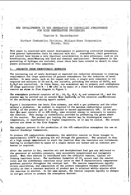
' NEW DEVELX)PMENTS IN THE GENERATION OF CONTROLLED ATMOSPHERES FOR HIGH TEMPERATURE PROCESSING __ - Charles W. Sanzenbacher Surface Combustion Division, Midland-Ross Corporation Toledo, Ohio This paper is concerned with recent developments in generating controlled atmospheres from gaseous hydrocarbon fuels by raaction with air. Atmospheres, their generation and control have become a very important consideration in many processes; such as ore benefication, metalbeating and food and chemical applications. Developments in the generating of hydrogen are excluded, since these have been covered in detail in other papers presented at this symposium. I. ADIABATIC (HIGH CCMBUSTIBLES) .GENERATOR The increasing use of newly 'developed or improved ore reduction processes is creating requirements for large quantities of gaseous atmospheres for the reduction of metal oxides., In many cases, such as for copper and iron, a single pure reductant is not required and mixtures of GO and H are suitable, providing the ratios of CO/C02 and 2 H /H20 are controlled. In these cases, one economical way to prepare such atmospheres it large quantities (100 M - 1 MM cfh) is by means of a fixed bed adiabatic catalytic reactor a# rhovn in flow diagram in Figure 1. The atmosphere produced consists of CO , CO, H2, H 0, N and unreacted CH , and the 2 process my be carried out in several kys dependizg on the relative concbntrations of the oxidizing and reducing agents needed. Figure 1 incorporates two basic flow schemes, one with a gas preheater and the other without a preheater. No preheat is required if the meximum combustibles content (CO+H ) of the product gas is not required to exceed approximately 459.. If the product $as must contain 45 to 60% CO+H2, some external energy is necessary to sustain the reaction. This energy is conveniently provided by preheating the gases ahead of the reactor. The product gas leaving the reactor may be discharged& reactor temperature, or superheated to a higher temperature, or it may be cooled, The several options are shown on the flow diagram. The simplest process is the production of the 45% combustibles atmosphere for use at reactor discharge temporature. To produce 45% combustibles atmosphere, the catalytic reactor is first brought to approximately 1200'F by passing hot air through the generator. The catalyst is then at a high enough temperature to start the reaction when the reactants are introduced. Heating is accomplished by means of a simple excess air burner and no indirect preheater is required. After the reactor is hot, reaction air and desulphurized fuel gas are delivered to the generator at suitable pressure, very accurately proportioned and intimately mixed. men this mixture is introduced into the catalytic reactor, typical re- forming reactions occur. The exothermic formation of C02 occurs near the reactor inlet and the endothermic reactions occur later so that a characteristic temperature gradient persists throughout the catalyst bed. The reactor temperatures rapidly attain equilibrium, and canposition of the product atmosphere becomes stabilized quickly so that a constant analysis of product gas is attained within minutes after the reaction is started. In the same manner, the reactor responds rapidly to changes in air-gas ratios to produce the atmosphere desired.
- Page 2 and 3: , 2 . I. - The reactor is shut down
- Page 4 and 5: 4 gases and non-uniform and incompl
- Page 6 and 7: EFFECT OF SPACE VELOCITY 8, TEMPERA
- Page 8 and 9: 8 NITROGEN GENERATOR FIGURE 7 - EXO
- Page 10 and 11: 10 Low Temperature Carbon Monoxide-
- Page 12 and 13: 12 The equilibrium constant for the
- Page 14 and 15: 14 pressure level with a subsequent
- Page 16 and 17: 16 References: - flj Storch, H. H.
- Page 18 and 19: 18 Table I1 Plant Operating Data; C
- Page 20 and 21: I Figure 4 - Low Temperature CO Con
- Page 22 and 23: The primary reaction may be steam r
- Page 24 and 25: 24 Radiation and convection losses,
- Page 26 and 27: AD 292 252. "Design Study Hydrogen
- Page 28 and 29: 28 / I i # I d i i 1 4
- Page 30 and 31: 30 HYDROGEN FROM NATURAL GAS FOR FU
- Page 32 and 33: 32 steam-to-as ratio. As In the stu
- Page 34 and 35: 34 anticipated, and a total system
- Page 36 and 37: 36 TEMPERATURE, OC Fig. 3.-CARBON M
- Page 38 and 39: 38 I CARBON MONOXIDE SHIFT METHANE
- Page 40 and 41: 40 Steam Naphtha' Reforming By The
- Page 42 and 43: 42 . -. Farben in the latter part o
- Page 44 and 45: 44 The zinc sulfide formed in the a
- Page 46 and 47: 46 In Great Britain, which conforme
- Page 48 and 49: 48 TABU I Production of Nitrogen Pr
- Page 50 and 51: z 0 I- I o 3 n 0 a n z W (3 0 U n >
' NEW DEVELX)PMENTS IN THE GENERATION OF CONTROLLED ATMOSPHERES<br />
FOR HIGH TEMPERATURE PROCESSING<br />
__ -<br />
Charles W. Sanzenbacher<br />
Surface Combustion Division, Midland-Ross Corporation<br />
Toledo, Ohio<br />
This paper is concerned with recent <strong>developments</strong> <strong>in</strong> generat<strong>in</strong>g <strong>controlled</strong> <strong>atmospheres</strong><br />
from gaseous hydrocarbon fuels by raaction with air. Atmospheres, <strong>the</strong>ir <strong>generation</strong><br />
and control have become a very important consideration <strong>in</strong> many processes; such as ore<br />
benefication, metalbeat<strong>in</strong>g and food and chemical applications. Developments <strong>in</strong> <strong>the</strong><br />
generat<strong>in</strong>g <strong>of</strong> hydrogen are excluded, s<strong>in</strong>ce <strong>the</strong>se have been covered <strong>in</strong> detail <strong>in</strong> o<strong>the</strong>r<br />
papers presented at this symposium.<br />
I. ADIABATIC (HIGH CCMBUSTIBLES) .GENERATOR<br />
The <strong>in</strong>creas<strong>in</strong>g use <strong>of</strong> <strong>new</strong>ly 'developed or improved ore reduction processes is creat<strong>in</strong>g<br />
requirements for large quantities <strong>of</strong> gaseous <strong>atmospheres</strong> for <strong>the</strong> reduction <strong>of</strong> metal<br />
oxides., In many cases, such as for copper and iron, a s<strong>in</strong>gle pure reductant is not<br />
required and mixtures <strong>of</strong> GO and H are suitable, provid<strong>in</strong>g <strong>the</strong> ratios <strong>of</strong> CO/C02 and<br />
2<br />
H /H20 are <strong>controlled</strong>.<br />
In <strong>the</strong>se cases, one economical way to prepare such <strong>atmospheres</strong><br />
it large quantities (100 M - 1 MM cfh) is by means <strong>of</strong> a fixed bed adiabatic catalytic<br />
reactor a# rhovn <strong>in</strong> flow diagram <strong>in</strong> Figure 1.<br />
The atmosphere produced consists <strong>of</strong> CO , CO, H2, H 0, N and unreacted CH , and <strong>the</strong><br />
2<br />
process my be carried out <strong>in</strong> several kys dependizg on <strong>the</strong> relative concbntrations<br />
<strong>of</strong> <strong>the</strong> oxidiz<strong>in</strong>g and reduc<strong>in</strong>g agents needed.<br />
Figure 1 <strong>in</strong>corporates two basic flow schemes, one with a gas preheater and <strong>the</strong> o<strong>the</strong>r<br />
without a preheater. No preheat is required if <strong>the</strong> meximum combustibles content<br />
(CO+H ) <strong>of</strong> <strong>the</strong> product gas is not required to exceed approximately 459.. If <strong>the</strong> product<br />
$as must conta<strong>in</strong> 45 to 60% CO+H2, some external energy is necessary to susta<strong>in</strong><br />
<strong>the</strong> reaction. This energy is conveniently provided by preheat<strong>in</strong>g <strong>the</strong> gases ahead<br />
<strong>of</strong> <strong>the</strong> reactor. The product gas leav<strong>in</strong>g <strong>the</strong> reactor may be discharged& reactor<br />
temperature, or superheated to a higher temperature, or it may be cooled, The several<br />
options are shown on <strong>the</strong> flow diagram.<br />
The simplest process is <strong>the</strong> production <strong>of</strong> <strong>the</strong> 45% combustibles atmosphere for use at<br />
reactor discharge temporature.<br />
To produce 45% combustibles atmosphere, <strong>the</strong> catalytic reactor is first brought to<br />
approximately 1200'F by pass<strong>in</strong>g hot air through <strong>the</strong> generator. The catalyst is <strong>the</strong>n<br />
at a high enough temperature to start <strong>the</strong> reaction when <strong>the</strong> reactants are <strong>in</strong>troduced.<br />
Heat<strong>in</strong>g is accomplished by means <strong>of</strong> a simple excess air burner and no <strong>in</strong>direct preheater<br />
is required.<br />
After <strong>the</strong> reactor is hot, reaction air and desulphurized fuel gas are delivered to<br />
<strong>the</strong> generator at suitable pressure, very accurately proportioned and <strong>in</strong>timately<br />
mixed. men this mixture is <strong>in</strong>troduced <strong>in</strong>to <strong>the</strong> catalytic reactor, typical re-<br />
form<strong>in</strong>g reactions occur. The exo<strong>the</strong>rmic formation <strong>of</strong> C02 occurs near <strong>the</strong> reactor<br />
<strong>in</strong>let and <strong>the</strong> endo<strong>the</strong>rmic reactions occur later so that a characteristic temperature<br />
gradient persists throughout <strong>the</strong> catalyst bed. The reactor temperatures rapidly<br />
atta<strong>in</strong> equilibrium, and canposition <strong>of</strong> <strong>the</strong> product atmosphere becomes stabilized<br />
quickly so that a constant analysis <strong>of</strong> product gas is atta<strong>in</strong>ed with<strong>in</strong> m<strong>in</strong>utes after<br />
<strong>the</strong> reaction is started. In <strong>the</strong> same manner, <strong>the</strong> reactor responds rapidly to changes<br />
<strong>in</strong> air-gas ratios to produce <strong>the</strong> atmosphere desired.
,<br />
2<br />
. I. -<br />
The reactor is shut down by simply clos<strong>in</strong>g <strong>the</strong> gas and air valves and allow<strong>in</strong>g <strong>the</strong><br />
reactor to cool. S<strong>in</strong>ce it is heavily <strong>in</strong>sulated, it will lose temperature slowly ard<br />
may bc restartet' without preheat<strong>in</strong>g for a number <strong>of</strong> hours after shutdown. The length<br />
OK time will depenc! on <strong>the</strong> size <strong>of</strong> <strong>the</strong> unit and its operat<strong>in</strong>g conditions. This is a<br />
very desirable feature for aFplicationsdcre gas demands are <strong>in</strong>termittent.<br />
The production <strong>of</strong> <strong>atmospheres</strong> conta<strong>in</strong><strong>in</strong>g zreater than 45% combustibles requires <strong>the</strong><br />
use <strong>of</strong> a preheater. This is an <strong>in</strong>direct heater used to heat <strong>the</strong> reactants dur<strong>in</strong>g<br />
normal operation and to heat <strong>the</strong> air to br<strong>in</strong>g <strong>the</strong> reactor to its start<strong>in</strong>g temperature.<br />
O<strong>the</strong>r components <strong>of</strong> <strong>the</strong> system are identical to <strong>the</strong> 45% combustibles generator.<br />
The temperature <strong>of</strong> <strong>the</strong> product gas leav<strong>in</strong>g <strong>the</strong> reactor is dependent upon <strong>the</strong> type <strong>of</strong><br />
fuel gas used, air-gas ratio and <strong>the</strong> degree <strong>of</strong> preheat en2loyed. It has been found<br />
that <strong>the</strong> water gas shift reaction (CO+H20~C02+H 0) stays <strong>in</strong> equilibrium with <strong>the</strong><br />
discharge gas temperature over a wide range <strong>of</strong> spa& velocities.<br />
determ<strong>in</strong>ed that <strong>the</strong> unreacted Methane content <strong>of</strong> <strong>the</strong> product gas varies <strong>in</strong> a pre-<br />
dictable manner with <strong>the</strong> discharge gas temperature and <strong>the</strong> space velocity. S<strong>in</strong>ce<br />
system heat losses are calcuable and small, it is feasible to calculate accurately<br />
<strong>the</strong> air-gas ratio, space velocity, and preheat required to produce a specific analysis<br />
<strong>of</strong> product gas. This <strong>in</strong> turn permits <strong>the</strong> rapid atta<strong>in</strong>ment <strong>of</strong> equilibrium conditions<br />
after start-up. Figure 2 shows typical reactor operat<strong>in</strong>g data, us<strong>in</strong>g natural gas or<br />
commercial propane fuels with <strong>the</strong> generator operat<strong>in</strong>g at rated capacity. Adjustments<br />
can be made to operate anywhere with<strong>in</strong> <strong>the</strong> limits <strong>of</strong> Tests 1 and 2 and also under<br />
somewhat leaner conditions than shown <strong>in</strong> Test 1. The relationship between Methane<br />
and rcactor discharge temperature and space velocity is shown <strong>in</strong> Figure 3.<br />
Major development considerations center around <strong>the</strong> proper design <strong>of</strong> <strong>the</strong> reactor<br />
catalyst bed, means for <strong>in</strong>troduc<strong>in</strong>g <strong>the</strong> reactants <strong>in</strong>to <strong>the</strong> bed, and <strong>the</strong> selection<br />
<strong>of</strong> suitable catalyst to make <strong>the</strong> process operate without exceed<strong>in</strong>g <strong>the</strong> temperature<br />
it limits and withouf carbon deposition. The equipment which has been developed<br />
successfully meets <strong>the</strong> application requirements.<br />
Approximate equipment and utilities costs for typical adiabatic reactors are shown<br />
on Figure 4. Equipment costs <strong>in</strong>clude air compressor and adequate <strong>in</strong>strumentation.<br />
Utilities are based on natural gas at 50C/M scf, and electric power at 3/4$/KWH.<br />
Product gas is at one atmosphere pressure and reactor temperature. A photograph <strong>of</strong><br />
a high combustibles adiabatic reactor is shown <strong>in</strong> Figure 5.<br />
11. NITROGEN GENERATOR<br />
It has also been<br />
Nitrogen generators are widely used throughout <strong>in</strong>dustry for purg<strong>in</strong>g, blanket<strong>in</strong>g,<br />
heat treat<strong>in</strong>g, and many o<strong>the</strong>r operations requir<strong>in</strong>g so called <strong>in</strong>ert <strong>atmospheres</strong> to<br />
<strong>in</strong>sure safe operation and/or improved process<strong>in</strong>g. The nitrogen for such applications<br />
can be provided by many methods. Small demands are satisfied by us<strong>in</strong>g cyl<strong>in</strong>der gas;<br />
larger requirements by on-site production via a variety <strong>of</strong> methods. One <strong>in</strong>expensive<br />
means is by remov<strong>in</strong>g C02and H 0 from <strong>the</strong> products <strong>of</strong> combustion <strong>of</strong> hydrocarbon fuels.<br />
2<br />
The nitrogen produced conta<strong>in</strong>s small concentrations <strong>of</strong> CO and H2 which are generally<br />
<strong>controlled</strong> between 0.5% and 4.077, mak<strong>in</strong>g <strong>the</strong> nitrogen sufficiently pure for <strong>the</strong><br />
majority <strong>of</strong> applications.<br />
At <strong>the</strong> present time numerous purification systems and generators have been developed<br />
and are be<strong>in</strong>g used for this purpose. The majority <strong>of</strong> such generators use an adsorption<br />
system to remove CO and refrigeration and/or adsorption systems for de-<br />
2<br />
hydration. Typically <strong>the</strong> C02 absorption system is a closed blonoethauolam<strong>in</strong>e (ME%)<br />
solution which absorbs C02 from <strong>the</strong> process gas and <strong>in</strong> turn is regenerated hy utiliz<strong>in</strong>g<br />
<strong>the</strong> exo<strong>the</strong>rmic heat <strong>of</strong> combustion released <strong>in</strong> <strong>the</strong> preparation <strong>of</strong> <strong>the</strong> process gas<br />
The adsorption dryers are normally <strong>of</strong> <strong>the</strong> <strong>the</strong>rmally reactivated alum<strong>in</strong>a type. These<br />
generators are highly developed, reliable and efficient mach<strong>in</strong>es, but are subject to<br />
corrosion problems. Over <strong>the</strong> years, considerable work has been done to circumvent<br />
this problem by many means, especially us<strong>in</strong>g dry adsorbent system to reriove both<br />
CO2 and H20. This developmental activity has <strong>in</strong>creased with <strong>the</strong> advent <strong>of</strong> hipher<br />
1<br />
c
capacity adsorbents such as <strong>the</strong> Molecular Sieves.<br />
Many systems have been devised to apply <strong>the</strong>se <strong>new</strong> adsorbents to <strong>the</strong> manufacture <strong>of</strong><br />
simple, reliable, and economical nitrogen gas generators. One method is shown dia-<br />
grammatically <strong>in</strong> Figure 6. Operation is generally as follows:<br />
Air and fuel gas are proportioned by suitable flow ration<strong>in</strong>g means and burned <strong>in</strong> an<br />
exo<strong>the</strong>rmic gas generator where<strong>in</strong> <strong>the</strong> products <strong>of</strong> combustion are cooled ei<strong>the</strong>r directly<br />
or <strong>in</strong>directly with cool<strong>in</strong>g water. The cooled gas conta<strong>in</strong>s nitrogen, generally<br />
with approximately 11% Cog and 1.0 to 4.0% combustibles. It is saturated with water<br />
at approximately cool<strong>in</strong>g water temperature. The cooled gas enters <strong>the</strong> right hand<br />
adsorb<strong>in</strong>g bed at a pressure slightly above one atmosphere. Both CO and H20 are<br />
adsorbed from <strong>the</strong> gas stream by <strong>the</strong> adsorbent <strong>in</strong> <strong>the</strong> tower, and thus<br />
2<br />
dry nitrogen<br />
conta<strong>in</strong><strong>in</strong>g essentially 1/2% to 2% CO and 1/2% to 2% H2 is produced.<br />
%ile <strong>the</strong> right hand bed is purify<strong>in</strong>g <strong>the</strong> process gas stream, <strong>the</strong> left hand bed is<br />
be<strong>in</strong>g reactivated. This is accomplished without heat by ma<strong>in</strong>ta<strong>in</strong><strong>in</strong>g <strong>the</strong> desorb<strong>in</strong>g<br />
bed under a vacuum dur<strong>in</strong>g <strong>the</strong> desorption cycle and utiliz<strong>in</strong>g some <strong>of</strong> <strong>the</strong> product nitrogen<br />
as a purge gas to sweep <strong>the</strong> desorbed CO and H 0 from <strong>the</strong> reactivat<strong>in</strong>g bed. Reactivation<br />
is accomplished without additionil heat<br />
2<br />
and at essentially ambient temperature.<br />
After reactivation <strong>the</strong> left tower is repressurized. The towers are cycled<br />
alternately so that one is adsorb<strong>in</strong>g e0 and H 0 at all times, and <strong>the</strong> o<strong>the</strong>r desorb<strong>in</strong>g<br />
or reactivat<strong>in</strong>g. A cont<strong>in</strong>uous flow <strong>of</strong> h.troge4 is ma<strong>in</strong>ta<strong>in</strong>ed from <strong>the</strong> system.<br />
Cycle times are less than 10 m<strong>in</strong>utes to ma<strong>in</strong>ta<strong>in</strong> essentially adiabatic conditions<br />
<strong>in</strong> <strong>the</strong> towers and to m<strong>in</strong>imize <strong>the</strong> quantity <strong>of</strong> dessicant required. Cycle time is<br />
determ<strong>in</strong>ed by <strong>the</strong> economics <strong>of</strong> nitrogen loss for purg<strong>in</strong>g and repressuriz<strong>in</strong>g, and<br />
pump down desorption times.<br />
The pressure sw<strong>in</strong>g system is automatic, simple, and has few components. Equipment<br />
costs &re comparable to MEA systems and utility costs are approximately 13c per MCF<br />
. nitrogen.<br />
Figure 7 is a photograph <strong>of</strong> a nitrogen generator <strong>of</strong> <strong>the</strong> type described.<br />
111. EXOTHERMIC GAS GENERATORS<br />
Because <strong>of</strong> <strong>the</strong>ir simplicity and economy, exo<strong>the</strong>rmic generators cont<strong>in</strong>ue to be used<br />
for processes and <strong>in</strong> applications <strong>in</strong> which nitrogen conta<strong>in</strong><strong>in</strong>g C02 and H 0 <strong>in</strong><br />
relatively high concentrations and CO, CH <strong>in</strong> small concentrations are nat detrimental.<br />
Many heat treat<strong>in</strong>g processes <strong>in</strong> ferrous and non-ferrous metallurgy utilize<br />
exo<strong>the</strong>rmic generator <strong>atmospheres</strong>. For example, <strong>the</strong> anneal<strong>in</strong>g <strong>of</strong> sheet steel,<br />
alum<strong>in</strong>um sheet, coils and foil, copper alloy and also <strong>the</strong> calc<strong>in</strong><strong>in</strong>g <strong>of</strong> charcoal, all<br />
represent uses <strong>of</strong> such <strong>atmospheres</strong> for high temperature processes. At lower temperatures<br />
exo<strong>the</strong>rmic generator <strong>atmospheres</strong> are used <strong>in</strong> gra<strong>in</strong> storage and for safety applications.<br />
Figure 8 shows <strong>the</strong> compositions <strong>of</strong> several typical <strong>atmospheres</strong> which may<br />
, be produced from exo<strong>the</strong>rmic generators. In many cases <strong>the</strong> generators are expected to<br />
operate over <strong>the</strong> entire range <strong>of</strong> air-gas ratios shown and <strong>the</strong>y must be designed<br />
accord<strong>in</strong>gly.<br />
The simplicity <strong>of</strong> exo<strong>the</strong>rmic gas generat<strong>in</strong>g equipment may be seen <strong>in</strong> Figure 9. The<br />
air-gas proportion<strong>in</strong>g system is identical to that used for <strong>the</strong> nitrogen generator.<br />
S<strong>in</strong>ce <strong>the</strong> ma<strong>in</strong> attribute <strong>of</strong> this type <strong>of</strong> atmosphere is its low equipment cost and<br />
operat<strong>in</strong>g economy, emphasis has been and is on produc<strong>in</strong>g more gas <strong>in</strong> a s<strong>in</strong>gle generator<br />
and at <strong>the</strong> same time decreas<strong>in</strong>g <strong>the</strong> physical dimensions <strong>of</strong> generators.<br />
The air-gas mix<strong>in</strong>g and burner system is probably <strong>the</strong> major consideration <strong>in</strong> <strong>the</strong> de-<br />
sign<strong>in</strong>g <strong>of</strong> exo<strong>the</strong>rmic generators. Poor mix<strong>in</strong>g will result <strong>in</strong> stratification <strong>of</strong> <strong>the</strong><br />
3
4<br />
gases and non-uniform and <strong>in</strong>complete combustion. Slightly rich or lean zones will<br />
develop at <strong>the</strong> mixer and burner and will persist throughout <strong>the</strong> combustion chamber.<br />
This will result <strong>in</strong> <strong>the</strong> production <strong>of</strong> exo<strong>the</strong>rmic pas conta<strong>in</strong><strong>in</strong>g some free oxygen <strong>in</strong><br />
a rich gas atmosphere or some combustibles <strong>in</strong> a lean gas atmosphere. This problem<br />
becomes more difficult as generator capacities <strong>in</strong>crease.<br />
An ideal mixer and burner system will <strong>in</strong>timately mix and allow <strong>the</strong> air and fuel gas<br />
streams to react <strong>in</strong> as short a time as possible <strong>in</strong> order to keep premix and combustion<br />
volumes at a m<strong>in</strong>imum. From a safety standpo<strong>in</strong>t a nozzle mix<strong>in</strong>g system is desirable<br />
s<strong>in</strong>ce it elim<strong>in</strong>ates hazardous premix volumes altoge<strong>the</strong>r and does not require fire<br />
checks. For large capacity generators this is especially desirable, s<strong>in</strong>ce o<strong>the</strong>rwise<br />
multiple fire check and burners are required, both <strong>of</strong> which <strong>in</strong>crease <strong>the</strong> cost and<br />
operat<strong>in</strong>g complexity <strong>of</strong> <strong>the</strong> equipment.<br />
The problem <strong>of</strong> develop<strong>in</strong>g a simple nozzle mix<strong>in</strong>g burner system for large generators<br />
is difficult and becomes more so as generators <strong>in</strong>crease <strong>in</strong> capacity. This is because<br />
<strong>of</strong> <strong>the</strong> longer mix<strong>in</strong>g paths associated with larger equipment.<br />
Many approaches to <strong>the</strong> problem have been used and much &velopment work has been done.<br />
Hydraulic studies, cold gaseous models us<strong>in</strong>g various tracer techniques and special<br />
hot probe studies have been employed to evaluate <strong>the</strong> characteristics <strong>of</strong> various<br />
mix<strong>in</strong>g and burner systems. As a result <strong>of</strong> such work, large nozzle mix<strong>in</strong>g burners<br />
have been developed which mix well with a m<strong>in</strong>imum expenditure <strong>of</strong> energy and promote<br />
complete combustion <strong>in</strong> a small volume. Figure 1 shows one such generator, 120,000<br />
scfh capacity, us<strong>in</strong>g a s<strong>in</strong>gle nozzle mix<strong>in</strong>g burner. Development is cont<strong>in</strong>u<strong>in</strong>g to<br />
<strong>in</strong>sure improved performance as <strong>the</strong> demand for generators <strong>of</strong> <strong>in</strong>creas<strong>in</strong>g capacities<br />
cont<strong>in</strong>ues.<br />
The generator shown <strong>in</strong> Figure 10 also <strong>in</strong>corporates a gas cool<strong>in</strong>g system which is an<br />
<strong>in</strong>tegral part <strong>of</strong> <strong>the</strong> unit. The purpose is, aga<strong>in</strong>, simplicity and sav<strong>in</strong>g <strong>of</strong> floor<br />
space. The cooler consists <strong>of</strong> an annular shaped packed tower surround<strong>in</strong>g <strong>the</strong> com-<br />
bustion chamber.<br />
Gas is passed upward through <strong>the</strong> cooler and is cooled by water flow-<br />
<strong>in</strong>g downward. Where it is necessary to employ <strong>in</strong>direct cool<strong>in</strong>g, condensate from <strong>the</strong><br />
products <strong>of</strong> combustion is cooled and recirculated through <strong>the</strong> cooler. This is one <strong>of</strong><br />
several compact cool<strong>in</strong>g systems which are be<strong>in</strong>g used successfully on exo<strong>the</strong>rmic<br />
generators at <strong>the</strong> present time.<br />
The general trend <strong>of</strong> virtually all classes <strong>of</strong> generators is towards more accurate<br />
control <strong>of</strong> product gas composition, <strong>in</strong>creas<strong>in</strong>g emphasis on automatic and simplified<br />
operation, and <strong>the</strong> production <strong>of</strong> <strong>in</strong>creas<strong>in</strong>g quantities <strong>of</strong> gases <strong>in</strong> smaller floor<br />
spaces at a lower capital expenditure. Cont<strong>in</strong>ually improv<strong>in</strong>g <strong>in</strong>strumentation for<br />
analysis and control and <strong>the</strong> development <strong>of</strong> analytical techniques aided by computers<br />
is permitt<strong>in</strong>g a better understand<strong>in</strong>g <strong>of</strong> <strong>the</strong> important mechanisms <strong>of</strong> gas generator<br />
systems and <strong>the</strong> development <strong>of</strong> improved equipment to meet <strong>in</strong>dustrial demands. The<br />
development <strong>of</strong> <strong>the</strong> three generators described <strong>in</strong> this paper are a direct result <strong>of</strong><br />
<strong>the</strong> modern technological advances <strong>of</strong> <strong>the</strong> last few years.
i<br />
REACTION<br />
FUEL GAS<br />
ADIABATIC CATALYTIC REACTOR FLOW SCHEME<br />
==I_=-<br />
- - ?- --'<br />
FUEL<br />
FIGURE 1<br />
ADIABATIC REACTOR OPERATING DATA<br />
PPP-<br />
AIR/GAS RATIO<br />
REACTANT PREHEAT<br />
MAXIMUM BED TEMPERATURE *F.<br />
'<br />
PROOUCT TEMPERATURE<br />
PRODUCT ANALYSIS - X<br />
co,<br />
co<br />
.F.<br />
H2<br />
CHI<br />
N2<br />
HZ0<br />
REACTOR<br />
PRODUCT PRODUCT<br />
GAS GbS<br />
--<br />
TEST-I TEST.2<br />
3.43 2.49<br />
NO YES<br />
1970 1700<br />
I500 I550<br />
2.7 0.25<br />
16.0 20.1<br />
28.9 m.3<br />
0.9 0.5<br />
51.5<br />
-<br />
40.3<br />
0.55<br />
FUEL' TESTS I AN0 2 - TOLE00 NATURAL GAS<br />
TEST 3 - COMMERCIAL PROPANE<br />
OPERATING PRESSURE - I ATMOSPHERE<br />
FIGURE '2<br />
I OR COOLER I<br />
L ________ 1<br />
TEST-J<br />
7.04<br />
YES<br />
2000<br />
1720<br />
0.3<br />
23.7<br />
30.6<br />
0.3<br />
44.6<br />
0.3
EFFECT OF SPACE VELOCITY 8, TEMPERATURE<br />
-=--<br />
ON RESIDUAL METHANE<br />
=--<br />
T<br />
-<br />
1300<br />
0 1.0 2.0 3.0<br />
% METHANE<br />
-- \e FULL FLOW<br />
4 FLOW<br />
FIGURE 3<br />
~-<br />
ADIABATIC REACTOR<br />
_____<br />
EQUIPMENT AND UTILITY COSTS<br />
---=<br />
EOUIPMENT COST UTILITY COST<br />
$ PER MSCF cot n2 1 PER MSCF CO +CH2<br />
FIGURL 6<br />
i<br />
E
t<br />
I<br />
REACTION<br />
5<br />
NITROG;; GE~ERATOR FLOW SCHEME<br />
.<br />
EXHAUST<br />
ADSORBER ADSORBER<br />
REACTIVATING ADSORBING<br />
cop. HpO<br />
FIGI!RE 6
8<br />
NITROGEN GENERATOR<br />
FIGURE 7<br />
-<br />
EXOTHERMIC GAS GENERATOR<br />
-<br />
TYPICAL GAS COMPOSITIONS<br />
AIR/GAS RATIO 6.2 9.0 10.0<br />
DRY ANALYSIS - MOL O/o<br />
COP 5.3 11.0 11.0<br />
co 9.8 1.3 0.0<br />
H2 10.4 0.7 0.0<br />
CH4 0. I 0.0 0.0<br />
02 0.0 0.0 1.3<br />
NO 0.0 0.0 0. I<br />
BASIS: TOLEDO NATURAL GAS, PRODUCTS AT ONE ATM.<br />
FIGURE 8
i-<br />
f<br />
i<br />
REACTION<br />
__________<br />
EXOTHERMIC GAS GENERATOR FLOW SCHEME<br />
WATER<br />
PaooucT<br />
9
10<br />
Low Temperature Carbon Monoxide-<br />
Conversion Catalysts<br />
Robert Habermehl<br />
Kenton Atwood<br />
Catalysts and Chemicals<br />
Louisville, Kentucky<br />
The purpose <strong>of</strong> this paper is to report on <strong>the</strong> <strong>in</strong>itial commercial operation <strong>of</strong> a low-<br />
temperature carbon monoxide conversion catalyst and to show some <strong>of</strong> <strong>the</strong> eccnomic<br />
advantages <strong>of</strong> us<strong>in</strong>g such a catalyst <strong>in</strong> <strong>the</strong> production <strong>of</strong> hydrogen and ammonia<br />
syn<strong>the</strong>sis gas.<br />
HISTORICAL: The production <strong>of</strong> hydrogen for mak<strong>in</strong>g ammonia syn<strong>the</strong>sis gas has<br />
reached major proportions. The quantity <strong>of</strong> hydrogen used <strong>in</strong> ammonia syn<strong>the</strong>sis<br />
<strong>in</strong> <strong>the</strong> U. S. last year exceeded 540 billion cubic feet, more than 1. 5 billion cubic<br />
feet per day. The consumption <strong>of</strong> hydrogen for ammonia syn<strong>the</strong>sis world-wide<br />
now exceeds 1500 billion cubic feet per year and is grow<strong>in</strong>g at <strong>the</strong> rate <strong>of</strong> somewhere<br />
between seven and ten per cent per year. In addition, <strong>the</strong> production <strong>of</strong> hydrogen<br />
for chemical hydrogenations and for hydrotreat<strong>in</strong>g and hydrocrack<strong>in</strong>g is becom<strong>in</strong>g<br />
an <strong>in</strong>creas<strong>in</strong>gly important factor <strong>in</strong> <strong>the</strong> consumption <strong>of</strong> hydrogen. Hydrocrack<strong>in</strong>g<br />
along with <strong>in</strong>creased ammonia production portends a cont<strong>in</strong>ued <strong>in</strong>crease <strong>in</strong> <strong>the</strong> requirements<br />
for more hydrogen production.<br />
Most <strong>of</strong> <strong>the</strong> hydrogen be<strong>in</strong>g consumed is produced by <strong>the</strong> reaction <strong>of</strong> steam with a<br />
hydrocarbon<br />
and is commonly referred to as "reform<strong>in</strong>g. Smaller quantities <strong>of</strong> hydrogen are<br />
produced by <strong>the</strong> partial oxidation <strong>of</strong> hydrocarbons by <strong>the</strong> reaction<br />
In order to maximize <strong>the</strong> quantity <strong>of</strong> hydrogen produced <strong>in</strong> <strong>the</strong>se processes, it is<br />
essential to convert <strong>the</strong> carbon monoxide to carbon dioxide and additional hydrogen<br />
by react<strong>in</strong>g it with steam<br />
GO + HzO = COZ + Hz<br />
This reaction is <strong>in</strong> equilibrium and tends to go to completion towards <strong>the</strong> right as<br />
<strong>the</strong> temperature is decreased. Pressure has no effect on <strong>the</strong> equilibrium. It,<br />
<strong>the</strong>refore, becomes desirable to promote this reaction at <strong>the</strong> lowest possible<br />
temperature. In order to <strong>in</strong>crease <strong>the</strong> reaction rate at which equilibrium<br />
2<br />
Inc .<br />
.' I<br />
' I
i<br />
I<br />
I/<br />
I'<br />
conditions are approached, it has been necessary to carry out <strong>the</strong> reaction <strong>in</strong> <strong>the</strong><br />
presence <strong>of</strong> a catalyst. The ca'talyst used almost exclusively.for this reaction<br />
for <strong>the</strong> last 40, to 50- years has. been an iron oxide-chrome,oxide, promoted catalyst.<br />
This catalyst caus,ed <strong>the</strong> r,eactjon to proceed,at commerciallp feasible rates at.<br />
temperatures ,a-s,low as 6.5.0°F, and it had a useful life <strong>of</strong> three'to'over ten years,<br />
depend<strong>in</strong>g on <strong>the</strong>,.cons'ervatism <strong>of</strong> <strong>the</strong> design.: A'lthough 0<strong>the</strong>.r catalysts have been<br />
<strong>in</strong>vestigated and reported (1) (2) for promot<strong>in</strong>g <strong>the</strong> reaction between carbon'<br />
monoxide and steam' at temperatiires 1owe.r. than 650"F, none have .found commercial<br />
acceptance, due pr<strong>in</strong>cipally to an impractically short life when used at<br />
near atmospheric. pressure. One low-temperature conversion catalyst, hnwexrer,<br />
found limited commercial acceptance when used at 'relatively high pressures.<br />
It 'was not untii 1953.that a commercial plant was constructed for <strong>the</strong> production<br />
<strong>of</strong> hydrogen for'<strong>the</strong> manufacture <strong>of</strong> ammonia syn<strong>the</strong>sis gas by steam-,hydrocarbon<br />
reform<strong>in</strong>g at pressures appreciably higher than atmospheric, approximately 90<br />
peig. S<strong>in</strong>c.e that time,most <strong>of</strong> <strong>the</strong> plants constructed operate at pressures rang<strong>in</strong>g<br />
from 75 to 300 psig. The plants formerly constructed to operate at near atmospheric<br />
pressure are now be<strong>in</strong>g replaced or converted <strong>in</strong>to plants operat<strong>in</strong>g at <strong>the</strong> higher<br />
pres sure s.<br />
In 1931 Larson (3) was granted a patent on a catalyst for promot<strong>in</strong>g <strong>the</strong> reaction<br />
between carbon monoxide and steam at temperatures as low as 540'F. A commercial<br />
plant was constructed early <strong>in</strong> <strong>the</strong> period <strong>of</strong> 1940-1950 for <strong>the</strong> production<br />
<strong>of</strong> hydrogen from water-gas for <strong>the</strong> manufacture <strong>of</strong> ammonia syn<strong>the</strong>sis pa&. The<br />
conversion <strong>of</strong> carbon monoxide to carbon dioxide and hydrogen was carried out<br />
over a catalyst apparently based on <strong>the</strong> Larson patent at appr0ximateJ.y 450 psig.<br />
Although exact operat<strong>in</strong>g temperatures and rates have never been published, <strong>the</strong>y<br />
. are .known to be <strong>in</strong> <strong>the</strong> range <strong>of</strong> 350' to 650"F, and space velocities <strong>of</strong> 400 to<br />
1000 SCF per cubic foot <strong>of</strong> catalyst. Even though <strong>the</strong> catalyst had a relatively<br />
short life, it cont<strong>in</strong>ued to be used even to <strong>the</strong> present time. This catalyst never<br />
found commercial acceptance for .low pressure operation, presumably because cf<br />
an impractically short life.<br />
,<br />
Catalysts and Chemicals Inc. , soon after its formation <strong>in</strong> 1957, started successful<br />
development work on <strong>the</strong> adaptation <strong>of</strong> a catalyst, <strong>in</strong> general similar to <strong>the</strong> Larson<br />
cataly-st, for promot<strong>in</strong>g <strong>the</strong> conversion <strong>of</strong> carbon monoxide <strong>in</strong> <strong>the</strong> temperature<br />
range f 350°.to 650°F. Over eight commercial charges <strong>of</strong> this catalyst, designated<br />
as are <strong>in</strong> operation or soon to gi <strong>in</strong> operation at pressures rang<strong>in</strong>g from<br />
near atmospheric to 350 psig; however, most <strong>of</strong> <strong>the</strong>se plants will operate at over<br />
100 psig. Pilot plant and commercial experience show that <strong>the</strong> catalyst will operate<br />
at rates appreciably <strong>in</strong> excess <strong>of</strong> those for <strong>the</strong> conventional iron oxide-chrome<br />
oxide type catalyst. With reasonable extrapolation <strong>of</strong> <strong>the</strong> available commercial<br />
experience, a practical life <strong>of</strong> at least one and one-half .to three years.'can be<br />
expected.<br />
PRINCIPAL ADVANTAGES OF C18 TYPE LOW-TEMPERA TURE CONVERSION<br />
CATALYST: The advantages <strong>of</strong> a low-temperature carbon monoxide conversion<br />
cztalyst <strong>in</strong> hydrogen production are obvious 'from a study <strong>of</strong> <strong>the</strong> equilibrium '<br />
reaction<br />
CO t HzC* = COZ t Hz<br />
11
12<br />
The equilibrium constant for <strong>the</strong> reaction has a value <strong>of</strong> 22 at 650"F, which is <strong>the</strong><br />
generally accepted m<strong>in</strong>imum effective temperature for <strong>the</strong> use <strong>of</strong> <strong>the</strong> iron oxidechrome<br />
oxide catalyst. The equilibrium constant is 207 at 400"F, which is a<br />
reasonable temperature for <strong>the</strong> C18 type low-temperature conversion catalyst.<br />
The practical significance <strong>of</strong> this is that at <strong>the</strong> same steam concentration, <strong>the</strong><br />
use <strong>of</strong> <strong>the</strong> C18 catalyst will result <strong>in</strong> over 99 per cent conversion <strong>of</strong> <strong>the</strong> carbon<br />
monoxide, whereas <strong>the</strong> iron oxide-chrome oxide catalyst will give only 90 to 95<br />
per cent conversion at its lowest effective temperature.<br />
If it is ass7imed that <strong>the</strong> process<strong>in</strong>g scheme for hydrogen production for <strong>the</strong> manufacture<br />
<strong>of</strong> ammonia syn<strong>the</strong>sis gas is <strong>the</strong> conventional steam-hydrocarbon reform<strong>in</strong>g-consist<strong>in</strong>g<br />
<strong>of</strong> a primary and secondary reformer followed by carbon monoxide conversion,<br />
carbon dioxide removal and <strong>the</strong>n methanation <strong>of</strong> <strong>the</strong> residual carbon<br />
monoxide--and that <strong>the</strong> acceptable level <strong>of</strong> residual carbon monoxide to be methanated<br />
is not more than 0. 3 mol per cent, <strong>the</strong> steam requirement for achiev<strong>in</strong>g this degree<br />
<strong>of</strong> conversion <strong>in</strong> a s<strong>in</strong>gle stage <strong>of</strong> carbon monoxide conversion with <strong>the</strong> usual <strong>in</strong>terstage<br />
cool<strong>in</strong>g is 3. 5 mols <strong>of</strong> steam per mol <strong>of</strong> dky feed gas when an iron oxidechrome<br />
oxide catalyst is used. When <strong>the</strong> C18 low-temperature conversion catalyst<br />
is used, <strong>the</strong> steam requirement is 0.7 mol per mol <strong>of</strong> dry feed gas, a reduction<br />
<strong>of</strong> 80 per cent. The greater quantity <strong>of</strong> steam required with <strong>the</strong> iron oxide-chrome<br />
oxide catalyst, however, is considered impractical and ei<strong>the</strong>r a lower quantity <strong>of</strong><br />
steam is used with a s<strong>in</strong>gle stage <strong>of</strong> conversion, followed by carbon dioxide removal<br />
and methanation, or two stages <strong>of</strong> carbon monoxide conversion are used with carbon<br />
aioxide removal after each stage, followed by methanation. In <strong>the</strong> first case,<br />
<strong>the</strong> carbon monoxide to be methanated ranges from 0.6 to 1.0 mol per cent. This<br />
greater quantity <strong>of</strong> carbon monoxide not only <strong>in</strong>creases <strong>the</strong> quantity <strong>of</strong> <strong>in</strong>erts <strong>in</strong> <strong>the</strong><br />
syn<strong>the</strong>sis gas, thus mak<strong>in</strong>g <strong>the</strong> syn<strong>the</strong>sis <strong>of</strong> ammonia less efficient, but for each<br />
mol <strong>of</strong> carbon monoxide methanated, 3 mols <strong>of</strong> hydrogen are consumed, requir<strong>in</strong>g<br />
a larger plant to produce <strong>the</strong> expected quantity <strong>of</strong> ammonia. In <strong>the</strong> second case<br />
where two stages <strong>of</strong> conversion are used, <strong>the</strong> carbon monoxide to be methanated<br />
does not exceed 0.3 mol per cent; however, considerably more equipment is required,<br />
consist<strong>in</strong>g <strong>of</strong> a stage o€ carbon dioxide removal, heaters, saturators,<br />
exchangers, coolers, etc. , which not only <strong>in</strong>crease <strong>the</strong> capital cost <strong>of</strong> <strong>the</strong> plant,<br />
but also <strong>the</strong> operat<strong>in</strong>g cost.<br />
The additional steam that must be added to <strong>the</strong> gas for <strong>the</strong> second stage conversion<br />
reaction br<strong>in</strong>gs <strong>the</strong> over-all steam requirements to 1.4 mols <strong>of</strong> steam per mol <strong>of</strong><br />
dry gas exit <strong>the</strong> secondary reformer. This is still twice <strong>the</strong> quantity <strong>of</strong> steam<br />
required for achiev<strong>in</strong>g <strong>the</strong> same degree <strong>of</strong> conversion <strong>in</strong> a s<strong>in</strong>gle stage conversion<br />
system us<strong>in</strong>g <strong>the</strong> low-temperature shift catalyst.<br />
These steam requirements for <strong>the</strong> three basic carbon monoxide conversion systems<br />
are summarized <strong>in</strong> Figure 1. Additional significance to <strong>the</strong> potential advantage <strong>of</strong><br />
<strong>the</strong> low-temperature shift catalyst can be seen by observ<strong>in</strong>g on <strong>the</strong> graph that <strong>the</strong><br />
steam level <strong>in</strong> <strong>the</strong> gas required to achieve a methane leakage <strong>of</strong> 0. 2 mol per cent<br />
from a secondary reformer is 0. 5 mol per mol <strong>of</strong> dry gas at 150 psig and 0.7 mol<br />
per mol <strong>of</strong> dry gas at 300 psig. It has already been <strong>in</strong>dicated that <strong>the</strong> 0. 7 steam to<br />
dry gas ratio is <strong>the</strong> required steam level to reach <strong>the</strong> 0. 3 per cent carbon monoxide<br />
level <strong>in</strong> <strong>the</strong> feed to <strong>the</strong> methanator. Fur<strong>the</strong>r, <strong>the</strong> practical steam levels required<br />
<strong>in</strong> <strong>the</strong> gas to supply <strong>the</strong> energy requirements <strong>of</strong> regenerat<strong>in</strong>g <strong>the</strong> carbon dioxide removal<br />
solution are shown for an am<strong>in</strong>e system and for one <strong>of</strong> <strong>the</strong> <strong>new</strong>er carbon dioxide<br />
removal systems. These steam to gas ratios are 1.40 and 0.70, respectively.
Once aga<strong>in</strong>, <strong>the</strong> 0.70 value appears a3d shows that <strong>the</strong> C18-i development is an<br />
important contributor to <strong>the</strong> advanc<strong>in</strong>g technology <strong>in</strong> ammonia syn<strong>the</strong>sis gas<br />
production.<br />
Figure l'also shows <strong>the</strong> relative physical size <strong>of</strong> <strong>the</strong> shift converters foy <strong>the</strong> three<br />
basic conversion systems. If <strong>the</strong> size requirement ,<strong>of</strong> <strong>the</strong> s<strong>in</strong>glestage system<br />
us<strong>in</strong>g <strong>the</strong> C18- 1 catalyst <strong>in</strong> conjunction with pre-conversion over a c'cmv.ent<strong>in</strong>rial<br />
catalyst is considered as 1, <strong>the</strong> size <strong>of</strong> <strong>the</strong> two-stage conventional catal.ys;.t system<br />
is 1.4 and for <strong>the</strong> s<strong>in</strong>gle-stage conventional catalyst system is 6. 0.<br />
The potentia.1 advantages <strong>of</strong> t.he low-temper2,tm-e shift catalyst <strong>in</strong> ammonia syn<strong>the</strong>sis<br />
gas production are fur<strong>the</strong>r shown <strong>in</strong> Table I, where<strong>in</strong> a comparison .is made <strong>in</strong> scme<br />
<strong>of</strong> <strong>the</strong> critical conditions and requirements for a hypo<strong>the</strong>tical 300 ton per day<br />
ammonia plant for <strong>the</strong> follow<strong>in</strong>g three alternate process<strong>in</strong>g schemes. The reformer<br />
pressure,level <strong>in</strong> all cases is 300 psig exit <strong>the</strong> reformer tubes.<br />
Case 1 A s<strong>in</strong>gle-stage conversion system employ<strong>in</strong>g conventional<br />
catalyst <strong>in</strong> series with low-temperature shift catslyst<br />
and us<strong>in</strong>g one cf <strong>the</strong> <strong>new</strong>er "lower energy" csrbon dioxide<br />
removal processes.<br />
Case 2 The same as Case 1 except employ<strong>in</strong>g comentional cata-<br />
lyst throughout <strong>the</strong> s<strong>in</strong>gle- stage converter and operat<strong>in</strong>g<br />
with higher <strong>in</strong>erts <strong>in</strong> <strong>the</strong> syn<strong>the</strong>sis gas loop.<br />
Case 3<br />
The same as Case 2 except us<strong>in</strong>g am<strong>in</strong>e as <strong>the</strong> carbdn<br />
dioxide removal system and obta<strong>in</strong><strong>in</strong>g a greater con-<br />
version <strong>of</strong> <strong>the</strong> carbon monoxide due to <strong>the</strong> higher steam<br />
requirements <strong>of</strong> <strong>the</strong> am<strong>in</strong>e system.<br />
Comparison <strong>of</strong> <strong>the</strong> hydrocarbon requirements <strong>in</strong> <strong>the</strong> above systems <strong>in</strong> TabIe X <strong>in</strong>dicates<br />
that <strong>the</strong> use <strong>of</strong> low-temperature shift catalyst permits <strong>the</strong> syn<strong>the</strong>es gas<br />
section <strong>of</strong> <strong>the</strong> plant to be reduced <strong>in</strong> size by approximately 12 per cent. The <strong>in</strong>creased<br />
cost <strong>of</strong> <strong>the</strong> catalyst required to give this advantage is approximately<br />
$50,000, <strong>in</strong>clud<strong>in</strong>g <strong>the</strong> use <strong>of</strong> a primary reform<strong>in</strong>g catalyst with <strong>the</strong> best known<br />
activity and heat transfer characteristics scch that full advantage can be taken <strong>in</strong><br />
reduc<strong>in</strong>g <strong>the</strong> physical size <strong>of</strong> <strong>the</strong> plant.<br />
Figure 2 shows <strong>the</strong> relative hydrocarbon requirements for <strong>the</strong> process, <strong>in</strong>clud<strong>in</strong>g<br />
fuel and steam production, for <strong>the</strong>se three systems <strong>of</strong> syn<strong>the</strong>sis gas production.<br />
The production <strong>of</strong> large quantities <strong>of</strong> relatively high-purity hydrogen, such as are<br />
necessary for <strong>the</strong> <strong>new</strong> hydrocrack<strong>in</strong>g <strong>of</strong> hydrocarbons processes, is ga<strong>in</strong><strong>in</strong>g rapidly<br />
<strong>in</strong> <strong>in</strong>dustrial importance. The typical plant <strong>in</strong>volves high pressure reform<strong>in</strong>g,<br />
s<strong>in</strong>gle-stage conversion, carbon dioxide removal, and methanation <strong>of</strong> residual<br />
carbon oxides. The degree <strong>of</strong> conversion <strong>of</strong> <strong>the</strong> carbon monoxide exit <strong>the</strong> reformer<br />
<strong>in</strong>fluences <strong>the</strong> ultimate cost <strong>of</strong> <strong>the</strong>se plants s<strong>in</strong>ce unconverted carbon monoxide ends<br />
up as a methane impurity <strong>in</strong> <strong>the</strong> product and affects <strong>the</strong> degree <strong>of</strong> reform<strong>in</strong>g to<br />
reach a given product purity. The greater conversion <strong>of</strong> carbon monoxide is made<br />
possible through <strong>the</strong> use <strong>of</strong> low-temperature shift catalyst and, <strong>the</strong>refore, permits<br />
a substantial reduction <strong>in</strong> <strong>the</strong> physical size <strong>of</strong> <strong>the</strong> reformer with attendant lower<br />
steam and fuel requirements, or alternatively, permits reform<strong>in</strong>g at a higher<br />
13
14<br />
pressure level with a subsequent reduction <strong>in</strong> compression costs.<br />
Figure 3 shows a comparison <strong>of</strong> a reformer design when us<strong>in</strong>g conventional cata-<br />
!yst versus <strong>the</strong> use <strong>of</strong> low-temperature carbon monoxide conversion catalyst<br />
and <strong>the</strong> best reform<strong>in</strong>g catalyst available. The size <strong>of</strong> <strong>the</strong> reformer <strong>in</strong> terms <strong>of</strong><br />
catalyst volume required and <strong>the</strong> maximum tube wall temperature <strong>in</strong> <strong>the</strong> reform<strong>in</strong>g<br />
furnace are plotted aga<strong>in</strong>st hydrogen purities <strong>of</strong> 95 to 98 per cent for a<br />
production capacity <strong>of</strong> 50 MMSGFD <strong>of</strong> net hydrogen delivered at 150 psig. It is<br />
shown that <strong>the</strong> use <strong>of</strong> <strong>the</strong> low-temperature canversion catalyst permits a 25 to<br />
30 per cent reduction <strong>in</strong> <strong>the</strong> size <strong>of</strong> <strong>the</strong> reformer.<br />
For example, <strong>in</strong> <strong>the</strong> case <strong>of</strong> 95 per cent hydrogen purity, it is observed that<br />
approximately 740 cubic feet <strong>of</strong> catalyst are required <strong>in</strong> <strong>the</strong> reformer when us<strong>in</strong>g<br />
<strong>the</strong> conventional catalyst, whereas approximately 550 cubic feet are required<br />
when us<strong>in</strong>g <strong>the</strong> low-temperature shift catalyst and <strong>the</strong> best reform<strong>in</strong>g catalyst<br />
available. The maximum tube wall temperature <strong>in</strong> both cases is 1670°F assum<strong>in</strong>g<br />
<strong>the</strong> same physical size <strong>of</strong> <strong>the</strong> tubes <strong>in</strong> terms <strong>of</strong> <strong>in</strong>side diameter and length <strong>in</strong> <strong>the</strong><br />
fired zone <strong>of</strong> <strong>the</strong> reformer. For 97 per cent hydrogen purity, when us<strong>in</strong>g <strong>the</strong> conventional<br />
catalyst, <strong>the</strong> reformer must conta<strong>in</strong> about 785 cubic feet <strong>of</strong> catalyst and<br />
<strong>the</strong> maximum tube wall temperature required is 1720°F. With C18 catalyst <strong>in</strong><br />
<strong>the</strong> shift converter, <strong>the</strong> reformer size may be reduced to conta<strong>in</strong> 665 cubic feet <strong>of</strong><br />
catalyst and <strong>the</strong> tube wall temperature required is now 1700°F.<br />
LABORATORY DEVELOPMENT AND COMMERCIAL DEMONSTRATION OF THE<br />
EFFECTIVENESS OF C18 LOW- TEMPERATURE CARBON MONOXIDE CONVERSION<br />
CATALYST: Bench scale and pilot plant work have been conducted <strong>in</strong> <strong>the</strong> laboratories<br />
<strong>of</strong> Catalysts and Chemicals Inc. to establish <strong>the</strong> preferred catalyst composition, <strong>the</strong><br />
best method <strong>of</strong> preparation <strong>of</strong> <strong>the</strong> catalyst, <strong>the</strong> method <strong>of</strong> reduction giv<strong>in</strong>g a catalyst<br />
<strong>of</strong> <strong>the</strong> highest activity, <strong>the</strong> optimum operat<strong>in</strong>g conditions, <strong>the</strong> effect <strong>of</strong> poisons, and<br />
<strong>the</strong> decl<strong>in</strong>e <strong>of</strong> activity with time on stream versus operat<strong>in</strong>g te'mperature. Specific<br />
studies were made on <strong>the</strong> effect <strong>of</strong> total pressure, <strong>the</strong> partial pressure <strong>of</strong> carbon<br />
dioxide, and <strong>the</strong> partial pressure <strong>of</strong> steam on <strong>the</strong> k<strong>in</strong>etics <strong>of</strong> <strong>the</strong> resction.<br />
It is not to be implied that <strong>the</strong> laboratory studies have resulted <strong>in</strong> complete answers<br />
to <strong>the</strong> quantitative effect <strong>of</strong> all <strong>the</strong> variables <strong>in</strong>volved; however, it is believed that<br />
sufficient <strong>in</strong>formation is known upon which to base workable designs at <strong>the</strong> usual<br />
process<strong>in</strong>g conditions.<br />
Life tests <strong>in</strong> excess <strong>of</strong> 13 months'duration were conducted at typical operat<strong>in</strong>g con-<br />
ditions.<br />
The first commercial charge <strong>of</strong> C18 was placed on stream on January 1. 1963 <strong>in</strong><br />
a 210 ton per day ammonia plant at about 120 psig. An operat<strong>in</strong>g mishap dur<strong>in</strong>g<br />
reduction <strong>of</strong> <strong>the</strong> catalyst and adverse conditions dur<strong>in</strong>g <strong>the</strong> <strong>in</strong>itial stages <strong>of</strong> operation<br />
resulted <strong>in</strong> below-normal <strong>in</strong>itial activity <strong>of</strong> <strong>the</strong> catalyst. Despite <strong>the</strong>se factors,<br />
however, <strong>the</strong> catalyst had sufficient activity to show a dist<strong>in</strong>ct advantage over <strong>the</strong><br />
previous conventional ca$alyst, and operation has cont<strong>in</strong>ued to <strong>the</strong> date <strong>of</strong> this<br />
writ<strong>in</strong>g with no more than <strong>the</strong> anticipated decl<strong>in</strong>e <strong>in</strong> activity. The <strong>in</strong>itial activity<br />
and <strong>the</strong> rate <strong>of</strong> decl<strong>in</strong>e <strong>in</strong> activity are shown <strong>in</strong> Figure 4. This charge <strong>of</strong> catalyst<br />
has been on stream for 12-1/2 months as <strong>of</strong> thls date.<br />
I.<br />
I<br />
i<br />
1<br />
i
TCs second commercial charge <strong>of</strong> C1S catalyst was placed on stream on May 11,<br />
!Q63 <strong>in</strong> a 260 ton per day ammonix plant on <strong>the</strong> West Coast. In contrast to <strong>the</strong><br />
f.rst charge <strong>of</strong> catalyst, <strong>the</strong> conditions <strong>of</strong> reduction and <strong>in</strong>itial operation were <strong>in</strong><br />
?c,crdance with <strong>the</strong> recommended procedures, and this charge <strong>of</strong> catalyst is con-<br />
t<strong>in</strong>u<strong>in</strong>g to operate at an <strong>in</strong>let temperature <strong>of</strong> 400"F, which was <strong>the</strong> <strong>in</strong>itial <strong>in</strong>let<br />
temperature. The relative activity level and decl<strong>in</strong>e <strong>in</strong> activity <strong>of</strong> this charge <strong>of</strong><br />
( ztalyst are shown <strong>in</strong> Figure 4, and specific data are presented <strong>in</strong> Table 11. The<br />
performance <strong>of</strong> this charge <strong>of</strong> catalyst has thus far exceeded <strong>the</strong> anticipated per-<br />
fsrmance based on <strong>the</strong> pilot plznt 'life tests.<br />
A rhird charge <strong>of</strong> Cl8 catalyst was placed <strong>in</strong> operation on July 24, 1963, operat<strong>in</strong>g<br />
on a slip stream <strong>of</strong> a reformer effluent at 2 psig. It cont<strong>in</strong>ues to perform satisfactorily,<br />
and <strong>the</strong> relative activity and decl<strong>in</strong>e <strong>in</strong> activity are shown <strong>in</strong> Figure 4.<br />
The design level <strong>of</strong> this operation, however, which was deduced from experiments<br />
3t low pressure, may prove to be uneconomical <strong>in</strong> many applications. Fur<strong>the</strong>r<br />
operat<strong>in</strong>g experience is required before <strong>the</strong> use <strong>of</strong> <strong>the</strong> catalyst can be encouraged<br />
At low pressures.<br />
As stated, Figure 4 shows <strong>the</strong> performance <strong>of</strong> <strong>the</strong> C18 catalyst <strong>in</strong> <strong>the</strong>se three commercial<br />
units. The relative activity with time on stream is shown <strong>in</strong> relation to<br />
<strong>the</strong> performance <strong>of</strong> <strong>the</strong> catalyst throughout <strong>the</strong> 13-month life test <strong>in</strong> CCI's pilot<br />
plant.<br />
A projection <strong>of</strong> <strong>the</strong>se curves <strong>in</strong>dicates an anticipated life <strong>of</strong> <strong>the</strong> catalyst <strong>of</strong> one<br />
and one-half to three years <strong>in</strong> commercial operation. A significant factor shown<br />
<strong>in</strong> Figure 4 is <strong>the</strong> commercial verification <strong>of</strong> <strong>the</strong> importance <strong>of</strong> reduction conditions<br />
3n <strong>the</strong> activity <strong>of</strong> low-temperature conversion catalysts when <strong>the</strong> performance <strong>in</strong><br />
Plants 1 and 2 is compared.<br />
As <strong>of</strong> this writ<strong>in</strong>g, five more commercial charges <strong>of</strong> C18 catalyst have been sold<br />
far startup <strong>in</strong> early 1964.<br />
SS'MMARY: The Cl8 low-temperature carbon monoxide conversion catalyst has<br />
been demonstrated commerciaily to <strong>of</strong>fer a proven economical life <strong>in</strong> hydrogen<br />
and ammonia syn<strong>the</strong>sis gas manufacture. The catalyst is, <strong>in</strong> general, more<br />
Fencitive to both catalyst poisons and abnormal operat<strong>in</strong>g conditions than is <strong>the</strong><br />
conventional iron oxide-chrome oxide catalyst and, <strong>the</strong>refore, requires more<br />
careful operation and greater attention to detail <strong>in</strong> process design. Specifically,<br />
<strong>the</strong> catalyst activity is severely affected by even trace quantities <strong>of</strong> sulfur <strong>in</strong> <strong>the</strong><br />
feed gas. The activity is appreciably affected by <strong>the</strong> subjection <strong>of</strong> <strong>the</strong> catalyst to<br />
temperatures <strong>in</strong> excess <strong>of</strong> <strong>the</strong> normal operat<strong>in</strong>g level.<br />
The C18 catalyst must be reduced under special conditions and with great care <strong>in</strong><br />
order to obta<strong>in</strong> maximum activity and long life. (5)<br />
Application <strong>of</strong> <strong>the</strong> catalyst <strong>in</strong> low pressure operations has not been shown to be<br />
practical and more Operat<strong>in</strong>g experience will be required before this can be<br />
de!er m<strong>in</strong>ed.<br />
The cataiyst has been proven to <strong>of</strong>fer an attractive payout factor <strong>in</strong> terms <strong>of</strong> <strong>in</strong>itial<br />
p: 3nt <strong>in</strong>vestment and operat<strong>in</strong>g economy. The ultimate life <strong>of</strong> <strong>the</strong> catalyst could well<br />
ex1 eed <strong>the</strong> projected m<strong>in</strong>imum <strong>of</strong> one and one-half to three years based on <strong>the</strong><br />
I ,mmercial operation to date.<br />
15
16<br />
References:<br />
-<br />
flj Storch, H. H. and P<strong>in</strong>kel, I. I., Industrial and Eng<strong>in</strong>eer<strong>in</strong>g Chemistry,<br />
29, 715; 1937..<br />
I<br />
(2) White, E. C. and Schdtz, J. F. , Industrial and Eng<strong>in</strong>eer<strong>in</strong>g Chemistry,<br />
26, 95-7; 1934.<br />
--I<br />
(3) U. S. Patent 1,797,426, March 24, 1931.<br />
j43 Patent application pend<strong>in</strong>g.<br />
'15)<br />
Patent application pend<strong>in</strong>g (on reduction procedure).
I<br />
I<br />
TABLE I<br />
Comparison <strong>of</strong> Process Design Features <strong>of</strong> Ammonia<br />
Syn<strong>the</strong> sis Gas Manufacture U s<strong>in</strong>g Low- Temperature<br />
Carbon Monoxide Conversion Catalyst<br />
Process Scheme: Steam-Hydrocarbon Reform<strong>in</strong>g,<br />
Primary and Secondary; 300 psig;<br />
Carbon Monoxide Conversion;<br />
Carbon Dioxide Removal;<br />
Methanation <strong>of</strong> Carbon Oxides.<br />
Basis: 300 Tons Per Day Ammonia<br />
Case : 1 2 3<br />
CO <strong>in</strong> Shift Converter 0. 2 mol per 1.1 mol per 0.5 mol per<br />
Effluent$&* cent, dry basis cent, dry basis cent, dry basis<br />
Inerts (CH4t A) Exit 29.89 70. 85 38. 30<br />
Methanator, mols /hr (0.96 mol per cent)(2. 1 mol per cent)(l. 21 mol per cent)<br />
Syn<strong>the</strong>sis Gas Required<br />
for 300 TPD NH3<br />
mols /hr<br />
Relative Amount<br />
Hydrocarbon, mols/hr<br />
Process Requirements<br />
Fuel Requirements<br />
Total Requirements<br />
Relative Amount<br />
Air, mols/hr<br />
Process Requirements<br />
Fuel Requirements<br />
Total Reqiirements<br />
Relative Amount<br />
3114.98<br />
100%<br />
702.44<br />
295.63<br />
998.07<br />
100%<br />
988.47<br />
2957.70<br />
3946.17<br />
100%<br />
3361.01<br />
107.9%<br />
788.11<br />
331.68<br />
1119.79<br />
112. 270<br />
1054. 25<br />
3318.42<br />
437 2.67<br />
110.81%<br />
3165.46<br />
101.6%<br />
720.68<br />
451.77<br />
1172.45<br />
11 7. 47%<br />
1001.99<br />
4519.74<br />
5521. 73<br />
139. 9370<br />
Steam Requirements<br />
Total Lbs/Hr 69,570 75,200 114, 350<br />
., Relative Amount 100% 108. 1% 164. 470<br />
Relative Reformer Size 100% 112.9% 103. 0%<br />
Relative Shift Converter 100%<br />
Size<br />
125. 1% 194. 670<br />
c Cases are def<strong>in</strong>ed <strong>in</strong> text.<br />
.I. ,. ". .,.<br />
Practical level <strong>of</strong> carbon monoxide <strong>in</strong> shift converter effluent us<strong>in</strong>g <strong>the</strong> steam<br />
requirements <strong>of</strong> <strong>the</strong> carbon dioxide re<strong>generation</strong> system to full effectiveness<br />
<strong>in</strong> <strong>the</strong> shift converter.<br />
17
18<br />
Table I1 Plant Operat<strong>in</strong>g Data; C18 Low-Temperature Carbon Monoxide<br />
Conversion Catalyst (260 Tons/Day Ammonia Plant, 120 PSIC)<br />
Days<br />
on<br />
Date Stream<br />
--<br />
5-24-63 13<br />
6-27-63 47<br />
9-4-63 116<br />
12-4-63 207<br />
i<br />
Dry Gas<br />
S. V. Inlet Outlet Inlet Gas Analyses, Mol Per Cent<br />
SCFH/ Temp. Temp. S/G<br />
V/Hr. OF "F Ratio C02 CO H2 CH4 N2 +A<br />
__I-___---<br />
---<br />
1925 410 445 0.336 In 4.2 3.0 71.4 0.2 21.2*<br />
out 7.0 0.02 72.4 0.2 20.39*<br />
1<br />
1980 400 450 0.42, In 0.8 3.0 74.0 0.3 21.9 4<br />
Out 3.8 0.06 74.0 0.3 21.8<br />
.J<br />
1800 402 453 0.38 In 0. 11 3.16 71.76 0.27 24.70<br />
Out 2.91 0.06 72.97 0.27 23.80 1<br />
1840 405 456 0.388 In 0.23 3.10 75.69 0.28 20.70<br />
Out 3.18 0.05 76.40 0.27 20.10<br />
*Analyses by customer's laboratory. Nitrogen and argon by difference.<br />
All o<strong>the</strong>r analyses by CCI chromatograph and were essentially confirmed<br />
by customer analyses.<br />
I<br />
!<br />
1<br />
I
c<br />
t<br />
1<br />
4-<br />
A - Low Temperature Catalyst .<br />
C<br />
M Q) Catalyst<br />
5 3- 4'<br />
V<br />
-<br />
B - 2-Stages Conventional Catalyst<br />
&I 6-<br />
U 0, c - I-Stage Conventional<br />
2<br />
w U<br />
U<br />
Q)<br />
3 2-<br />
0<br />
U<br />
.r(<br />
ld<br />
d<br />
m<br />
6 1-<br />
0<br />
e<br />
E<br />
ld<br />
i2<br />
C<br />
U<br />
m<br />
0 -<br />
-- -I---<br />
-- T- - - - - - -<br />
----.-<br />
---I-<br />
.<br />
B<br />
----e<br />
2-<br />
0<br />
Relative Catalyst Volumes<br />
- C<br />
S/C Levels Required For:<br />
Am<strong>in</strong>e Re<strong>generation</strong><br />
- + 0.2% CH4 at 300 PSIC<br />
Sulf<strong>in</strong>ol Re<strong>generation</strong> and<br />
0. 270 CH4 at 150 PSIG<br />
(Exit Secondary)<br />
Figure 2 - Low Temperature CO Conversion Catalyst (C18)<br />
4 8<br />
Case 2<br />
Case 3<br />
(5522)<br />
Case I-Low Temperature<br />
Catalyst and Sulf<strong>in</strong>ol<br />
Case 2-One Stage Conventiod<br />
i Catalyst and Sulf<strong>in</strong>ol<br />
I<br />
Case 3-One Stage Conwntional<br />
I Catalyst and Am<strong>in</strong>e<br />
Mols/Hour CH4 Required for 300 Tons/Day NH, at 300 PSIG'<br />
Reform<strong>in</strong>g<br />
,
I<br />
Figure 4 - Low Temperature CO Conversion Catalyst<br />
c Commercial Performance <strong>of</strong> C18<br />
M<br />
and Life Test Results<br />
Plant 3 - 2 psig<br />
Plant 2 - 120 psig<br />
CCI Life Test - 150 psig<br />
-*Plant 1 - 120 psig<br />
I<br />
0 2 4 6 8 10 12 14 16 18 20 22<br />
Time on Stream (Months)
Ultra Pure Hydrogen for Fuel Cell Operation<br />
H. H. Geissler<br />
Engelhard Industries, Inc.<br />
Process Equipment Division<br />
The first practical fuel cells to be developed used pure oxygen<br />
and hydrogen. It has proven to be quite feasible to adopt certa<strong>in</strong><br />
<strong>of</strong> <strong>the</strong>se cells to use air at <strong>the</strong> oxygen electrode, .that is, <strong>the</strong> cathode-'<br />
An <strong>in</strong>tensive effort is underway to develop cells which can use<br />
a more convenient fuel at <strong>the</strong> anode.2 However, it appears unlikely<br />
that such cells will be available for practical application <strong>in</strong> <strong>the</strong><br />
near future.<br />
One alternate approach is to separate a conversion function from<br />
<strong>the</strong> cell and modify <strong>the</strong> anode to use an impure hydrogen-rich gas. It<br />
is relatively simple, for example, to dissociate ammonia3 and it would<br />
appear to be easier to modify <strong>the</strong> anode to handle <strong>the</strong> result<strong>in</strong>g 75%<br />
hydrogen <strong>in</strong> nitrogen mixture than it was to modify <strong>the</strong> cathode to han-<br />
dle <strong>the</strong> 21% oxygen <strong>in</strong> nitrogen mixture which is air. Residual fuel<br />
gas from <strong>the</strong> anode can <strong>the</strong>n be burned to supply <strong>the</strong> energy require-<br />
ments <strong>of</strong> <strong>the</strong> dissociation reaction. This method <strong>of</strong> operation has re-<br />
cently been described by \<br />
Produc<strong>in</strong>g a hydrogen-rich gas from hydrocarbons (or from oxygenated<br />
hydrocarbon derivatives such as alcohols) requires appreciably<br />
more elaborate conversion equipment and <strong>the</strong> product gas stream will<br />
conta<strong>in</strong> a variety <strong>of</strong> impurities. Methane, carbon monoxide, carbon<br />
dioxide, nitrogen and water vapor may all be <strong>in</strong> <strong>the</strong> hydrogen-rich<br />
stream. The presence <strong>of</strong> <strong>the</strong>se impurities <strong>in</strong>troduces a large number<br />
<strong>of</strong> problems with respect to <strong>the</strong> development <strong>of</strong> anodes and to <strong>the</strong> design<br />
<strong>of</strong> <strong>the</strong> fuel cell battery system. The conditions for efficient<br />
operation <strong>of</strong> gas diffusion electrodes with gases conta<strong>in</strong><strong>in</strong>g <strong>in</strong>erts<br />
have been developed by Baucke and ~ <strong>in</strong>sel.~ In <strong>the</strong> case <strong>of</strong> gases conta<strong>in</strong><strong>in</strong>g<br />
potential catalyst poisons, however, it may well be much more<br />
desirable to comb<strong>in</strong>e hydrogen purification with <strong>the</strong> fuel conversion<br />
function so that only pure hydrogen need enter <strong>the</strong> cell.<br />
The production <strong>of</strong> hydrogen for fuel cell applications has been<br />
explored for a considerable time. A number <strong>of</strong> reports prepared recently<br />
<strong>in</strong>dicate <strong>the</strong> difficulties which arise <strong>in</strong> scal<strong>in</strong>g down conventional<br />
processes for manufactur<strong>in</strong>g hydrogen.6r7r Conventional process<strong>in</strong>g<br />
schemes are as shown <strong>in</strong> Figure 1.<br />
21
The primary reaction may be steam reform<strong>in</strong>g or<br />
partial combustion or a comb<strong>in</strong>ation <strong>of</strong> <strong>the</strong> two.<br />
In any event it <strong>in</strong>volves a high temperature en-<br />
do<strong>the</strong>rmic reaction to which heat energy must be<br />
supplied. .<br />
Carbon monoxide removal is generally accomplished<br />
by <strong>the</strong> catalysed water gas shift reaction where<strong>in</strong><br />
carbon monoxide reacts with water vapor to form<br />
carbon dioxide plus hydrogen. Recent advances <strong>in</strong><br />
catalyst composition permit this reaction to proceed<br />
at commercially operable rates at moderate<br />
temperatures. 9* lo The advantage is that <strong>the</strong> equilibrium<br />
is sufficiently favorable so as to require<br />
only a s<strong>in</strong>gle stage <strong>of</strong> shift reaction <strong>in</strong> a plant<br />
produc<strong>in</strong>g about 99% purity hydrogen.<br />
Formerly sev-<br />
eral stages with <strong>in</strong>termediate carbon dioxide removal<br />
were required. While <strong>the</strong> shift reaction is exo<strong>the</strong>r-<br />
mic <strong>the</strong> temperature level is such that <strong>the</strong> heat is<br />
not generally usefully recoverable.<br />
Carbon dioxide removal is done at near ambient tem-<br />
peratures by scrubb<strong>in</strong>g <strong>the</strong> gas with suitable regen-<br />
erable basic reagents. A variety <strong>of</strong> reagents and<br />
processes are available. l1t l2 l3<br />
F<strong>in</strong>al purification is <strong>of</strong>ten accomplished by catalyt-<br />
ically hydrogenat<strong>in</strong>g <strong>the</strong> residual oxides <strong>of</strong> carbon<br />
to <strong>the</strong> much less objectionable impurity methane,<br />
followed by dry<strong>in</strong>g <strong>the</strong> product hydrogen stream. Al-<br />
ternately cold box process<strong>in</strong>g, generally <strong>in</strong>volv<strong>in</strong>g<br />
a liquid nitrogen wash, can be used.<br />
It is evident that scal<strong>in</strong>g down conventional equipment without sig-<br />
nificantly alter<strong>in</strong>g <strong>the</strong> process steps cannot result <strong>in</strong> any appre-<br />
ciable reduction <strong>of</strong> equipment components <strong>in</strong> small hydrogen generators<br />
for fuel cell use.<br />
The Engelhard Hydrogen Process provides a <strong>new</strong> improved approach<br />
for solv<strong>in</strong>g <strong>the</strong>se problems by comb<strong>in</strong><strong>in</strong>g three basic concepts :<br />
- a hydrogen produc<strong>in</strong>g reaction<br />
- <strong>the</strong> removal <strong>of</strong> pure product hydrogen<br />
- <strong>the</strong> utilization <strong>of</strong> <strong>the</strong> residue as fuel to<br />
supply <strong>the</strong> energy requirements <strong>of</strong> <strong>the</strong> process.<br />
This makes it possible to design and construct compact hydrogen gen-<br />
erators. The process is schematically <strong>in</strong>dicated <strong>in</strong> Figure 2.<br />
1
I..<br />
I,<br />
I<br />
t<br />
. The dissociation <strong>of</strong> ammonia is a suitable hydrogen produc<strong>in</strong>g<br />
reaction. An earlier paper14 describes <strong>the</strong> design, construction<br />
and performance <strong>of</strong> a m<strong>in</strong>iature generator.deliver<strong>in</strong>g 4 SCFH <strong>of</strong> hy-<br />
drogen to serve a 200 watt fuel cell. This unit was developed for<br />
<strong>the</strong> Electronics Research and Development Laboratories <strong>of</strong> <strong>the</strong> United<br />
States Army.<br />
Hydrogen generators based on hydrocarbons are <strong>of</strong> much greater<br />
general <strong>in</strong>terest. Engelhard is currently engaged <strong>in</strong> construct<strong>in</strong>g<br />
a number <strong>of</strong> liquid hydrocarbon fueled hydrogen generators hav<strong>in</strong>g<br />
hydrogen output capacities <strong>in</strong> <strong>the</strong> range <strong>of</strong> 4 to 600 SCFH.<br />
Steam reform<strong>in</strong>g <strong>of</strong> hydrocarbons lends itself well to <strong>the</strong> Engel-<br />
hard Hydrogen Process because <strong>the</strong> energy required for <strong>the</strong> process is<br />
liberated outside <strong>of</strong> <strong>the</strong> reaction zone ra<strong>the</strong>r than with<strong>in</strong> it as <strong>in</strong><br />
<strong>the</strong> case <strong>of</strong> partial combustion. Thus <strong>the</strong> residual fuel gas can be<br />
used to operate <strong>the</strong> process.<br />
While various hydrogen removal methods may be considered, diffusion<br />
through a material permeable only to hydrogen accomplishes<br />
<strong>the</strong> objectives <strong>in</strong> one simple step and can be readily adapted for<br />
use <strong>in</strong> small hydrogen generators such as we are discuss<strong>in</strong>g here.<br />
Palladium and palladium alloys are well known for <strong>the</strong>ir ability to<br />
diffuse hydrogen. Several reviews <strong>of</strong> <strong>the</strong> hydrogen permeation process<br />
have recently been presented.1sn1Bm17<br />
The process is unique <strong>in</strong> that<br />
it supplies <strong>the</strong> purest grade <strong>of</strong> hydrogen available: ultra-pure hy-<br />
drogen conta<strong>in</strong><strong>in</strong>g no impurities measurable by presently available<br />
techniques. Use <strong>of</strong> ultra-pure hydrogen greatly simplifies fuel cell<br />
battery design. With no impurities contam<strong>in</strong>ation <strong>of</strong> <strong>the</strong> electrolyte<br />
does not occur, nor do <strong>in</strong>ert gases accmulate. The requirement <strong>of</strong><br />
vent<strong>in</strong>g such gases which would complicate <strong>the</strong> mechanical design <strong>of</strong><br />
a fuel cell battery can be elim<strong>in</strong>ated with ultra-pure hydrogen.<br />
The Engelhard Hydrogen Process is a highly efficient way <strong>of</strong> pro-<br />
duc<strong>in</strong>g hydrogen. This becomes particularly important if it is to be<br />
considered as a component <strong>of</strong> a fuel cell power source package. Now<br />
consider <strong>the</strong> energy balance <strong>of</strong> a hydrogen generator as shown <strong>in</strong> Fig-<br />
ure 2, for <strong>the</strong> steam reform<strong>in</strong>g version with liquid water and liquid<br />
hydrocarbon feed streams. In pr<strong>in</strong>ciple <strong>the</strong> energy content <strong>of</strong> <strong>the</strong><br />
product hydrogen would be <strong>the</strong> same as <strong>the</strong> gross heat<strong>in</strong>g value <strong>of</strong> <strong>the</strong><br />
hydrocarbon feed and <strong>the</strong> generator would have an energy conversion<br />
efficiency <strong>of</strong> 10%. For this <strong>the</strong> follow<strong>in</strong>g conditions would have to<br />
be met: The product hydrogen and <strong>the</strong> flue gas leave <strong>the</strong> apparatus<br />
at <strong>the</strong> same temperature as <strong>the</strong> <strong>in</strong>com<strong>in</strong>g stEeams. The water con-<br />
ta<strong>in</strong>ed <strong>in</strong> <strong>the</strong> flue gas is discharged as a liquid. No radiation and<br />
convection heat losses occur. In practice <strong>the</strong>se idealized condi-<br />
tions cannot be realized.<br />
The temperatures <strong>of</strong> <strong>the</strong> output streams can be brought to rel-<br />
atively low levels by heat exchange, output hydrogen aga<strong>in</strong>st <strong>in</strong>-<br />
com<strong>in</strong>g combustion air, flue gas aga<strong>in</strong>st fuel and water feed streams.<br />
It is not feasible, however, to usefully recover <strong>the</strong> latent heat <strong>of</strong><br />
<strong>the</strong> water vapor <strong>in</strong> <strong>the</strong> flue gas, and this may represent a sizeable loss.<br />
23
24<br />
Radiation and convection losses,depend upon <strong>the</strong> size and<br />
arrangement <strong>of</strong> <strong>the</strong> apparatus, and vary from very small relative<br />
to <strong>the</strong> gross heat<strong>in</strong>g value <strong>of</strong> <strong>the</strong> fuel fed, <strong>in</strong> large generators,<br />
to as much as 20% <strong>in</strong> very m<strong>in</strong>iaturized generators.<br />
The energy loss represented by any excess water fed as a<br />
liquid but discharged as a vapor <strong>in</strong> <strong>the</strong> flue gas is one reason<br />
for operat<strong>in</strong>g at <strong>the</strong> lowest possible molal water to carbon ratios.<br />
Ano<strong>the</strong>r reason is to reduce <strong>the</strong> water vapor content <strong>of</strong> <strong>the</strong> reformed<br />
gas stream and hence to <strong>in</strong>crease <strong>the</strong> partial pressure <strong>of</strong> hydrogen<br />
<strong>in</strong> <strong>the</strong> diffusion zone. This reduces <strong>the</strong> amount <strong>of</strong> palladium alloy<br />
required and <strong>the</strong> overall size and weight <strong>of</strong> <strong>the</strong> apparatus. A third<br />
reason is that if <strong>the</strong> ratio is sufficiently low a comb<strong>in</strong>ed hydrogen<br />
generator-fuel cell power source could operate with no external<br />
water supply if <strong>the</strong> fuel cell can be eng<strong>in</strong>eered so that <strong>the</strong> water<br />
produced from <strong>the</strong> hydrogen consumed is returned to <strong>the</strong> steam re-<br />
form<strong>in</strong>g hydrogen generator.<br />
There is currently a great <strong>in</strong>terest <strong>in</strong> develop<strong>in</strong>g improved cat-<br />
18,19<br />
alysts for <strong>the</strong> steam reform<strong>in</strong>g <strong>of</strong> normally liquid hydrocarbons.<br />
Moreover, for universally useable hydrogen generator-fuel cell power<br />
sources a catalyst is required capable <strong>of</strong> steam reform<strong>in</strong>g any type<br />
<strong>of</strong> currently available hydrocarbon fuel, <strong>in</strong> particular gasol<strong>in</strong>e, jet<br />
fuel, and diesel fuel meet<strong>in</strong>g present military specifications. Such<br />
catalysts do not appear to be available at <strong>the</strong> present.<br />
In <strong>the</strong> Engelhard hydrogen generators now be<strong>in</strong>g built proprie-<br />
tary catalysts are be<strong>in</strong>g used which have demonstrated <strong>the</strong> ability<br />
to steam reform a wide variety <strong>of</strong> hydrocarbon structures, i.e. par-<br />
aff<strong>in</strong>s, naph<strong>the</strong>nes, olef<strong>in</strong>s, aromatics, Commercial-fuels such as<br />
BTX raff<strong>in</strong>ates (essentially Cg-Cgparaff<strong>in</strong>s) , light naphthas, and jet<br />
fuels such as JP-4 have been steam reformed with <strong>the</strong>se catalysts at<br />
molar water to carbon atom ratios <strong>of</strong> three or lower, with runs <strong>of</strong><br />
over 1000 hours, provided <strong>the</strong> sulfur content was below 40 ppm. In<br />
tests with o<strong>the</strong>r commercial fuels hav<strong>in</strong>g higher sulfur contents, ex-<br />
cessively rapid catalyst deterioration was observed, which we have<br />
ascribed to sulfur poison<strong>in</strong>g.<br />
The maximum sulfur content permitted by military specifications<br />
for JP-4 is 4000 parts per million;20 we have found it <strong>in</strong>terest<strong>in</strong>g<br />
that batch after batch <strong>of</strong> Jp-4, from at least one ref<strong>in</strong>er, has con-<br />
sistently analysed under 50 ppm. We believe this reflects how overly<br />
liberal sulfur specifications are <strong>in</strong> this day <strong>of</strong> modern ref<strong>in</strong>eries.<br />
Nowadays sulfur removal <strong>of</strong> ten occurs <strong>in</strong>cidentally to o<strong>the</strong>r process<strong>in</strong>g<br />
and is frequently done to protect <strong>the</strong> process equipment and catalysts<br />
used by <strong>the</strong> ref<strong>in</strong>er. When and if direct conversion <strong>of</strong> hydrocarbons<br />
<strong>in</strong> fuel cells becomes a reality a sulfur problem is likely to arise<br />
<strong>the</strong>re also. It would appear reasonable and desirable that any <strong>new</strong><br />
fuel specifications be written with low sulfur limits.<br />
Return<strong>in</strong>g to <strong>the</strong> mechanical aspects, it must be remembered<br />
that although <strong>the</strong> Engelhard Hydrogen Unit is appreciably simpler
than o<strong>the</strong>r hydrogen manufactur<strong>in</strong>g processes it still requires a<br />
number <strong>of</strong> components and controls. There are ways <strong>of</strong> design<strong>in</strong>g<br />
certa<strong>in</strong> very small generators to operate without any auxiliary<br />
electric power, but <strong>in</strong> general pumps and blowers and controllers<br />
are necessary, all <strong>of</strong> which require power.<br />
One version is illustrated <strong>in</strong> a simplified schematic flow<br />
diagram, Figure 3. Fuel and water are metered to <strong>the</strong> system <strong>in</strong><br />
fixed ratio by controll<strong>in</strong>g <strong>the</strong> speeds <strong>of</strong> positive displacement<br />
pumps to supply adequate feed for <strong>the</strong> hydrogen demand at any <strong>in</strong>-<br />
stant. The feed stream is heated <strong>in</strong> a flue gas exchanger, it is<br />
<strong>the</strong>n reformed and product hydrogen removed <strong>in</strong> <strong>the</strong> reactor/diffusor.<br />
The hydrogen stream is cooled aga<strong>in</strong>st <strong>in</strong>com<strong>in</strong>g combustion air, which<br />
is metered by a speed <strong>controlled</strong> positive displacement blower. The<br />
residual fuel gas from <strong>the</strong> reactor/diffusor passes through a high<br />
temperature back pressure control valve, on to <strong>the</strong> furnace burner<br />
where it is burned with <strong>the</strong> <strong>controlled</strong> combustion air. The flow<br />
rates <strong>of</strong> <strong>the</strong> fuel/water feed'and <strong>the</strong> combustion air must be closely<br />
<strong>controlled</strong> to ma<strong>in</strong>ta<strong>in</strong> high efficiency. Feed, air, and product hy-<br />
drogen flows are not l<strong>in</strong>early r'elated, which complicates <strong>the</strong> control<br />
system.<br />
The <strong>in</strong>terplay between generator size and weight, efficiency,<br />
and power requirement is complex. Optimization is particularly<br />
difficult and critical <strong>in</strong> generators for mobile fuel cell power<br />
systems. There is need for more efficient auxiliary equipment than<br />
now available. For example, <strong>in</strong> one 140 SCFH unit under construction,<br />
<strong>the</strong>oretical feed pump power is 2 watts, air blower power 50 watts,<br />
while actual available equipment requires 200 watts and 400 watts<br />
respectively .<br />
REFERENCES<br />
Yeager, E., Science 134 1178 Oct. 20, 1961<br />
"Fuel Cells, Volume wo" edited by G.<br />
New York, 1963<br />
J. Jug, Re<strong>in</strong>hold,<br />
Rosenblatt, E. F. and Cohn, J. G., U.S. 2,601,221 (1952)<br />
Allmanna Svenska Elektriska A.B., Swedish Patent 5589/62.<br />
Baucke, W. and W<strong>in</strong>sel, A., Advanced Energy Conversion<br />
(1963)<br />
AD 292 134. "Design Study <strong>of</strong> a Hydrogen-Generat<strong>in</strong>g Plant<br />
for Submar<strong>in</strong>e Use Based on <strong>the</strong> Steam Reform<strong>in</strong>g <strong>of</strong> Methanol,"<br />
for Bureau <strong>of</strong> Ships Contract NObs 86744, The M. W. Kellogg<br />
Co-, N. Y., September 30, 1962.<br />
25
AD 292 252. "Design Study Hydrogen Generation from Light<br />
Petroleum Distillate, " for Bureau <strong>of</strong> Ships Contract NObs<br />
86747, Chemical Construction Corp., N. Y., September 28, 1962.<br />
AD 292 273. "Design Study on The Generation <strong>of</strong> Hydrogen<br />
from Methanol For Fuel Cell Systems on Board Submar<strong>in</strong>es,"<br />
for Bureau <strong>of</strong> Ships Contract NObs 86743, G irdler Corp.,<br />
Louisville, October 12, 1962.<br />
Moe, J. M., Division <strong>of</strong> Petroleum Chemistry, A.C.S., Pre-<br />
pr<strong>in</strong>ts 8, No. 4, B-29 (1963).<br />
Habermehl, R., "L& Temperature Carbon Monoxide Shift Cat-<br />
alyst. " (Paper to be presented at 147th N ational Meet<strong>in</strong>g,<br />
American Chemical Society, Philadelphia, April 5-10, 1964 .)<br />
.Stotler, H. H., "Acetone Process for Removal <strong>of</strong> Carbon<br />
Dioxide from Hydrogen", paper presented at 49th N ational<br />
A.I.Ch. E. Meet<strong>in</strong>g, New Orleans, La. (March 14, 1963).<br />
Deal, C. H., Dunn, C. L., Hill, E. S., Papadopoulos, M. N.,<br />
and Zarker, K. E., "Sulf<strong>in</strong>ol - A New Process for Gas Puri-<br />
f ication" , paper presented at 6th World Petroleum Congress,<br />
June, 1963.<br />
Kohl, A. L. and Riesenfeld, F. C. , "Gas Purification", McGraw-<br />
Hill, New York, 1960.<br />
Geissler, H. H., Proceed<strong>in</strong>gs - 17th Annual Power Sources<br />
Conference, May, 1963.<br />
Cohn, G. and Straschel, H. K., Division <strong>of</strong> Petroleum Chemistry,<br />
A.C.S., Prepr<strong>in</strong>ts €3, No. 4, B-43 (1963).<br />
Hunter, J. B., u, page B-49.<br />
. .<br />
Rub<strong>in</strong>, L. R., Engelhard Industries Technical Bullet<strong>in</strong>.2<br />
No. 1, 8 (1961).<br />
FOX, J. M. and Yarze, J. C., Division <strong>of</strong> Petroleum Chemistry,<br />
A. C. S. , Prepr<strong>in</strong>ts g,, No. 4, B-21 (1963) .<br />
Voogd, J. , and Tielrooy, J. , Hydrocarbon Process<strong>in</strong>g. & Petro-<br />
leum Ref<strong>in</strong>er 42 No. 3, 144 (1963).<br />
Specification MIL- J-5624D8 JP-4.
FIGURE I<br />
HYDROGEN MANUFACTURING PROCEDURES<br />
He.<br />
215<br />
270<br />
270<br />
236<br />
CO<br />
65<br />
IO<br />
IO<br />
-<br />
MOLS -<br />
co2<br />
30<br />
85<br />
I<br />
-<br />
CH4<br />
5<br />
5<br />
5<br />
16<br />
FIGURE 2<br />
ENGELHARD HYDROGEN PROCESS<br />
FLUE GAS<br />
t<br />
H2 0<br />
75<br />
20<br />
20<br />
-<br />
f<br />
390<br />
390<br />
306<br />
252<br />
27
28<br />
/<br />
I<br />
i<br />
# I<br />
d<br />
i<br />
i<br />
1<br />
4
i<br />
I:<br />
A Hydrogen-Generat<strong>in</strong>g Plant for Submar<strong>in</strong>e Fuel-Cell<br />
Use Based on Methanol Decomposition<br />
W. H. Heffndr, A. C. Veverka andG. T. Skaperdae<br />
M. W. Kellogg Company<br />
Ne-w Yolk 17, New York<br />
ABSTRACT<br />
A design study <strong>of</strong> a hydrogen-generat<strong>in</strong>g plant based on <strong>the</strong><br />
decomposition <strong>of</strong> methanol and <strong>in</strong>tended as a source <strong>of</strong> hydrogen for<br />
fuel cells to be used <strong>in</strong> submar<strong>in</strong>e propulsion is reported. The plant<br />
is designed to supply 20 pounds per hour <strong>of</strong> ultrapure hydrogen normally<br />
(70 pounds per hour maximum) and is optimized on <strong>the</strong> basis <strong>of</strong> m<strong>in</strong>imum<br />
volume and weight, m<strong>in</strong>imum oxygen consumption, maximum efficiency,<br />
maximum simplicity and reliability, m<strong>in</strong>imum hazard, m<strong>in</strong>imum ma<strong>in</strong>-<br />
tenance, and m<strong>in</strong>imum cost. For ten days <strong>of</strong> cont<strong>in</strong>uous operation at<br />
normal capacity, <strong>the</strong> hydrogen-generat<strong>in</strong>g equipment and fuels (methanol<br />
and oxygen for combustion) represent a comb<strong>in</strong>ed specific weight <strong>of</strong><br />
about 1.0 lb. /kwh and a specific volume <strong>of</strong> 0.018 cu. ft. /kwh.
30<br />
HYDROGEN FROM NATURAL GAS FOR FUEL CELLS<br />
John Meek and 8. 5. Baker<br />
Institute <strong>of</strong> Gas Technology<br />
Chlcago 16, llllnols<br />
INTRODUCTION<br />
, _<br />
To be proctlcal, any commerclal fuel cell system for use wlth natural gas must be competltlve<br />
wlth exlstlng power <strong>generation</strong> schemes. Under thls strlngent economlc Ilmitatlon, many potentlal<br />
fuel cell systems are elim<strong>in</strong>ated. A review <strong>of</strong> <strong>the</strong> more common fuel cells (Table 1) summarlres <strong>the</strong><br />
authors' estimate <strong>of</strong> <strong>the</strong>se systems, based only on <strong>the</strong> crlterlon <strong>of</strong> economic feasiblllty for use In <strong>the</strong><br />
gas Industry.<br />
At <strong>the</strong> beglnnlng <strong>of</strong> 1963, a low-temperature fuel cell program was lnltlated at <strong>the</strong> lnstltute <strong>of</strong><br />
Gas Technology to study <strong>the</strong> use <strong>of</strong> reformed natural gas and alr In acld fuel cells. Thls system, based<br />
on <strong>the</strong> use <strong>of</strong> Impure hydrogen, does not appear to have been extenslvely studled elsewhere. The<br />
followlng conslderatlons motlvated this course <strong>of</strong> study;<br />
1. Natural gas (methane) Is difficult to react dlrectly at low temperatures<br />
In fuel cells.<br />
2. Hydrogen Is known to be a good tuel cell fuel at low temperatures.<br />
3. Natural gas Is an easlly reformed hydrocabon fuel.<br />
4. Reformed natural gas wlll conta<strong>in</strong> about 80 mole percent hydrogen.<br />
5. An acid cell, In pr<strong>in</strong>ciple, does not requlre a hlgh-purlty hydrogen<br />
feed.<br />
The present paper Is concerned wlth that portlon <strong>of</strong> <strong>the</strong> IGT program devoted to <strong>the</strong> productlon<br />
from natural gas <strong>of</strong> a hydrogen-rlch feed which Is compattble wlth economic fuel cell operatlon.<br />
The oblectives set forth for <strong>the</strong> hydrogen <strong>generation</strong> system were dlctated by economlc as<br />
well as practlcal feasiblllty. The proiect was gulded by <strong>the</strong> followlng goals:<br />
1. Low-cost components.<br />
2. Maxlmum methane converslon.<br />
3. M<strong>in</strong>imum carbon monoxlde content.<br />
4. No movlng parts.<br />
5. Low system pressure drop.<br />
~.<br />
1<br />
I
The need for low-cost components with low pressure drop ellmlnated conventional palladium<br />
diffuser purlficatlon schemes. The Impracticability <strong>of</strong> hav<strong>in</strong>g mov<strong>in</strong>g parts In small generators (deliver<strong>in</strong>g<br />
2- to 100-kilowatt fuel cells) elim<strong>in</strong>ated scrubb<strong>in</strong>g towers, <strong>of</strong>ten used <strong>in</strong> larger hydrogen<br />
purification processes. Maximum me!hane conversion is essential to obta<strong>in</strong> high efflctency. The<br />
desirability <strong>of</strong> a low carbon monoxide concentration resulted from Information derived from <strong>the</strong> fuel<br />
cell portion <strong>of</strong> <strong>the</strong> program. All <strong>of</strong> <strong>the</strong> above goals are based on <strong>the</strong> needs <strong>of</strong> on-site generatlon<br />
systems for use <strong>in</strong> <strong>the</strong> gas Industry.<br />
THE HYDROGEN GENERATION SYSTEM<br />
To achieve <strong>the</strong> deslgn goals outl<strong>in</strong>ed above, a multi-stage process was necessary. The scheme<br />
studied was a three-stage process made up <strong>of</strong> <strong>the</strong> follow<strong>in</strong>g steps:<br />
Reform<strong>in</strong>g: CH4 + H20 +3H2 + CO<br />
Shlft<strong>in</strong>g: CO + H20 eC02 + H2 (2)<br />
Methanation: CO + 3H24CH4 + H20<br />
The overall process Is shown schematically In Figure 1.<br />
Methane Reform<strong>in</strong>g<br />
Reaction (1) be<strong>in</strong>g well-known, it was <strong>the</strong> Intent <strong>of</strong> this study to establish operat<strong>in</strong>g parameters<br />
whlch might be useful <strong>in</strong> <strong>the</strong> constructlon <strong>of</strong> small hydrogen generators. Experiments were conducted<br />
<strong>in</strong> reactors capable <strong>of</strong> providlng power for a fuel cell system <strong>of</strong> a few hundred watts. S<strong>in</strong>ce most<br />
experlence with <strong>the</strong>se reactions is wlth larger systems, It was felt that scaleup <strong>in</strong> this <strong>in</strong>stance would<br />
be relatively straightforward.<br />
A steel reactor 1 <strong>in</strong>ch <strong>in</strong> diameter and 18 <strong>in</strong>ches long was fllled to a 4-Inch bed height with<br />
Girdler G-56B catalyst, which was reduced In sire to give a reactor diameter-to-particle size ratio <strong>of</strong><br />
about 10:il The total pressure drop through <strong>the</strong> reactor at a space velocity <strong>of</strong> 1000 SCF per CU. ft.<br />
<strong>of</strong> catalyst per hour was only 1 <strong>in</strong>ch <strong>of</strong> water. A steam-to-methane mole ratio <strong>of</strong> 3:l was chosen, and<br />
studies were made at space velocities <strong>of</strong> 500 and 1000 SCF per cu. ft. <strong>of</strong> catalyst per hour at a<br />
variety <strong>of</strong> temperatures. Effluent gas was analyzed chromatographically for carbon monoxide and meth-<br />
ane with a Fisher-Gulf partitioner us<strong>in</strong>g a charcoal column. The only o<strong>the</strong>r detectable carbon-conta<strong>in</strong>-<br />
<strong>in</strong>g species present, carbon dioxidqwas determ<strong>in</strong>ed from a mass balance.<br />
The results <strong>of</strong> <strong>the</strong>se experiments (Figure 2) show that methane conversion was a strong function<br />
<strong>of</strong> space velocity with respect to <strong>the</strong> temperature required to achieve complete conversion, higher<br />
temperature be<strong>in</strong>g required for higher space velocitles. Far <strong>the</strong> space velocities studied, complete<br />
conversion was obta<strong>in</strong>ed at 80OOC. and above. The exit gas carbon monoxide content was not a strong<br />
function <strong>of</strong> space velocity, and <strong>the</strong> effluent carbon monoxide concentratton at 800°C. was about 15<br />
mole %. At <strong>the</strong> lower space velocity, experiments conducted at temperatures up to 1000°c. resulted<br />
<strong>in</strong> a fur<strong>the</strong>r <strong>in</strong>crease <strong>in</strong> carbon monoxide concentration. S<strong>in</strong>ce <strong>the</strong> ultimate goal is a low carbon mon-<br />
oxide content <strong>in</strong> <strong>the</strong> fuel cell feed gas, operat<strong>in</strong>g at this high temperature is undesirable. Also, from<br />
a <strong>the</strong>rmal efficiency standpo<strong>in</strong>t <strong>the</strong> lowest posslble reform<strong>in</strong>g temperature Is most desirable. Hqv<strong>in</strong>g<br />
established reasonable operat<strong>in</strong>g limits for <strong>the</strong> reform<strong>in</strong>g stage, <strong>the</strong> effluent from <strong>the</strong> reformer was used<br />
as <strong>the</strong> <strong>in</strong>put to <strong>the</strong> shlft reactor.<br />
Carbon Monoxide Shift' ,<br />
Conventional shlft processes operatlng between 3OOo and 500%. requlre, to achieve a low car-<br />
bon monoxide content (3000 parts per million or less), <strong>the</strong> use <strong>of</strong> a carbon dloxide absorption stage, whlch<br />
is unwleldy for use In small systems. Recently work done by Moe E) <strong>in</strong>dicated that reformed and shifted<br />
gases conta<strong>in</strong><strong>in</strong>g 2000 to 3000 parts per mllllon carbon monoxide could be achieved without carbon<br />
dloxlde removal if a low-temperature (175O to 300%.) shlft catalyst was used. This relatively <strong>new</strong><br />
catalyst, Glrdler G-66, was placed In a reactor <strong>of</strong> 1-Inch diameter and 18-<strong>in</strong>ch length, filled to a bed<br />
helght <strong>of</strong> 8 Inches, and <strong>the</strong> shift reaction was studied wlth respect to temperature, space velocity, and<br />
(1)<br />
(3)<br />
31
32<br />
steam-to-as ratio. As In <strong>the</strong> study <strong>of</strong> <strong>the</strong> reform<strong>in</strong>g reaction, <strong>the</strong> carbon monoxide and methane con-<br />
tents <strong>of</strong> <strong>the</strong> effluent gas stream were analyzed chromatographically.<br />
The re;ults <strong>of</strong> thls study are shown <strong>in</strong> Flgures 3 and 4. In Flgure 3, <strong>the</strong> effects <strong>of</strong> space veloclty<br />
and temperature on <strong>the</strong> carbon monoxide content <strong>of</strong> <strong>the</strong> effluent gas are <strong>in</strong>dicated. At <strong>the</strong> hlgher space<br />
velocity, 1000 SCF per cu. ft. <strong>of</strong> catalyst per hour, <strong>the</strong> desired reduction <strong>in</strong> <strong>the</strong> carbon monoxide<br />
content <strong>of</strong> <strong>the</strong> effluent gos could not be obta<strong>in</strong>ed. Experiments at still higher space velocities, 2000<br />
SCF per cu. ft. <strong>of</strong> catalyst per hour, yielded much poorer results, not reported here. However, at<br />
o space velocity <strong>of</strong> 500 SCF per cu. ft.<strong>of</strong> catalyst per hour, a m<strong>in</strong>imum <strong>in</strong> <strong>the</strong> carbon monoxide<br />
concentration is seen to occur at obout 2670C. In Flgure 4, <strong>the</strong> strong effect <strong>of</strong> <strong>the</strong> steam content <strong>of</strong><br />
<strong>the</strong> react<strong>in</strong>g mlxture on <strong>the</strong> effluent carbon monoxide concentration is <strong>in</strong>dicated. At 25ooC., a cont<strong>in</strong>uous<br />
reduction <strong>in</strong> <strong>the</strong> carbon monoxlde content isobta<strong>in</strong>ed as <strong>the</strong> steam-to-methane ratio is <strong>in</strong>creased.<br />
The maxlmum ratio tested was 7.3:1, os this ratio readily yielded a carbon monoxide content which was<br />
known to be fur<strong>the</strong>r reducible by methanation. Whe<strong>the</strong>r additional steam is deslroble will be decided<br />
later on <strong>the</strong> basis <strong>of</strong> <strong>the</strong> cost <strong>of</strong> <strong>the</strong> steam, ai well as <strong>the</strong> fuel cell performance on impure hydrogen<br />
feed.<br />
Carbon Monoxide Methanation<br />
Reaction 3, methanatlon, posed <strong>the</strong> greatest challenge <strong>in</strong> <strong>the</strong> overall carbon monoxlde reduction<br />
process. The first attempts at achtev<strong>in</strong>g an effective reduction <strong>in</strong> <strong>the</strong> carbon monoxide content <strong>of</strong> a<br />
syn<strong>the</strong>tic gas conta<strong>in</strong><strong>in</strong>g 80 mole % hydrogen, 19.7 mole % carbon dioxide, and 0.3 mole % carbon<br />
monoxide, us<strong>in</strong>g conventional methanation catalysis, were unsuccessful. Ei<strong>the</strong>r <strong>of</strong> two events occurred.<br />
At very low temperatures no reactions occurred, while at higher temperatures <strong>the</strong> water gos shift was<br />
promoted along with methanatlon and at best only a slight decrease, and In some cows an actual In-<br />
crease, In carbon monoxide was observed.<br />
The problem was to f<strong>in</strong>d a catalyst which would permit selective methanation <strong>of</strong> carbon monoxlde<br />
<strong>in</strong> <strong>the</strong> presence <strong>of</strong> carbon dioxide, under condltions <strong>in</strong> which <strong>the</strong> latter Is present <strong>in</strong> concentratlonr two<br />
orders <strong>of</strong> magnltude greater than <strong>the</strong> former. The need for selectlve methanation Is tw<strong>of</strong>old. If appre-<br />
ciable amounts <strong>of</strong> <strong>the</strong> carbon dioxide react, <strong>the</strong> exo<strong>the</strong>rmic nature <strong>of</strong> <strong>the</strong> reaction almost ensures a<br />
complete loss <strong>of</strong> temperature control <strong>in</strong> <strong>the</strong> system. As <strong>the</strong> temperature rises, mare carbon dioxide Is<br />
methanated and large amounts <strong>of</strong> hydrogen ore consumed. In <strong>the</strong> limit<strong>in</strong>g case, all <strong>of</strong> <strong>the</strong> hydrogen<br />
and carbon dioxide could react to form methane. Equilibrium calculations clearly lndlcated <strong>the</strong> desir-<br />
ability <strong>of</strong> low-tempeiature operation, although even under <strong>the</strong>se condltions <strong>the</strong> sought-after reduction<br />
dld not appear achievable.<br />
Us<strong>in</strong>g <strong>the</strong> above-mentloned gas compos1 tion, experlments were conducted with a ru<strong>the</strong>nlum-on-<br />
alum<strong>in</strong>a catalyst obtalned from Englehard Industries, Inc. The effluent gas composltlon was analyzed<br />
wlth <strong>the</strong> afore-mentioned chromatograph and a M<strong>in</strong>e Safety Appliances Co. Lira <strong>in</strong>frared analyzer.<br />
With <strong>the</strong> <strong>in</strong>frared analyzer, carbon monoxlde was determ<strong>in</strong>ed with an accuracy <strong>of</strong> about 10 parts per<br />
million. Aga<strong>in</strong>, a variety <strong>of</strong> parameters were studied, Includ<strong>in</strong>g excess water, and <strong>the</strong> results are<br />
shown In Figures 5 and 6. The excess water tests were made to ascertaln at what stage In <strong>the</strong> hydrogen<br />
<strong>generation</strong> system it would be most favorable to remove water.<br />
In Flgure 5, <strong>the</strong> carbon monoxide content <strong>of</strong> <strong>the</strong> exit gas Is seen as a function <strong>of</strong> temperature<br />
for <strong>the</strong> case <strong>of</strong> 2 male % water vapor <strong>in</strong> <strong>the</strong> feed. Dlst<strong>in</strong>ct mlnlmums <strong>in</strong> carban monoxlde content -<br />
about 100 parts per mllllon, dependent on space veloclty and temperature -are seen. It Is <strong>in</strong>terest<strong>in</strong>g<br />
that, for Increas<strong>in</strong>g space velocity, <strong>the</strong> same m<strong>in</strong>tmum carbon monoxlde content is obtalned, but at<br />
higher temperatures. In Figure 6, <strong>the</strong> some parameters are studied wlth a feed gas contalnlng 15% water<br />
vapor. Aga<strong>in</strong>, <strong>the</strong> same m<strong>in</strong>imum carbon monoxide concentration is obta<strong>in</strong>ed, but at slightly higher<br />
temperatures. It was also observed that, <strong>in</strong> <strong>the</strong> range <strong>of</strong> mlnlmurn carbon monoxlde content, no apprecl-<br />
able conversion <strong>of</strong> carbon dlaxlde to methane occurred! hence, <strong>the</strong> reactlon can be cansldered htghly<br />
selective. The carban monoxlde reductlon process Is summarlzed <strong>in</strong> Flgure 7.
Complete Hydrogen Generation System 33 1<br />
After complet<strong>in</strong>g <strong>the</strong> experimental work on <strong>the</strong> reactions described above, reform<strong>in</strong>g, shift, and<br />
methanation reactors were connected <strong>in</strong> series, and <strong>the</strong> complete system was analyzed. A natural gas<br />
conta<strong>in</strong><strong>in</strong>g about 95% methane and 5% higher hydrocarbons was passed through a sulfur removal<br />
cartrldge and fed to <strong>the</strong> flrst reactor stage, where it was reformed <strong>in</strong> <strong>the</strong> presence <strong>of</strong> excess steam (stem-<br />
to-gas mole ratio <strong>of</strong> 7.3:l) at a space velocity <strong>of</strong> 250 SCF per cu. ft. <strong>of</strong> catalyst per hour at 80Ooc.<br />
The effluent from this reactor was fed to <strong>the</strong> shift reactor operat<strong>in</strong>g at a space velocity <strong>of</strong> 500 SCF per<br />
cu. ft. <strong>of</strong> catalyst per hour at 27OoC. The effluent from this stage was fed to a condenser where a por-<br />
tion <strong>of</strong> <strong>the</strong> excess water was removed, and <strong>the</strong> remaln<strong>in</strong>g gas mixture was fed to <strong>the</strong> methanatlon reactor<br />
operated at a space velocity <strong>of</strong> 1000 SCF per CU. ft. <strong>of</strong> catalyst per hour and at a temperature <strong>of</strong> 190°C.<br />
The total system pressure drop was 4 <strong>in</strong>ches <strong>of</strong> water column. The product gas was analyzed to be 78 mole<br />
% hydrogen, 19.7 mole % carbon dioxide, 0.3 mole % methane, 2 mole % water, and 8 pats per<br />
million carbon monoxide. The carbon monoxide was analyzed on a special MSA Lira <strong>in</strong>frared analyzer<br />
with a sensitivlty <strong>of</strong> 2 parts per million.<br />
The tenfold improvement <strong>in</strong> performance compared with <strong>the</strong> previous experiment i s not readily<br />
expla<strong>in</strong>able. Some improvement hud been antlcipoted on <strong>the</strong> basis that <strong>the</strong> orig<strong>in</strong>al methanation<br />
experiments were performed with a feed gas conta<strong>in</strong><strong>in</strong>g about 3400 parts per milllon carbon monoxide,<br />
while <strong>the</strong> actual shift reaction reduced that concentration by almost a factor <strong>of</strong> 2. Experiments are<br />
belng cont<strong>in</strong>ued to study fur<strong>the</strong>r <strong>the</strong> effects <strong>of</strong> steam-to-methane ratio, space velocity, and catalyst<br />
life. Experimental evidence from <strong>the</strong> fuel cell portion <strong>of</strong> <strong>the</strong> program <strong>in</strong>dicates that <strong>the</strong> above-<br />
mentloned carbon monoxide content can be readily tolerated by <strong>the</strong> hydrogen electrode.<br />
EFFICIENCY AND ECONOMICS<br />
One <strong>of</strong> <strong>the</strong> most attractive features <strong>of</strong> fuel cells is <strong>the</strong>ir potentially hlgh efficiency. When m<br />
oddltlonal process<strong>in</strong>g stage,such as <strong>the</strong> one just described, Is added to <strong>the</strong> fuel cell system, a reductlan<br />
<strong>in</strong> overall efficiency may be anticipated. To place <strong>the</strong> external reformer-fuel cell system <strong>in</strong> <strong>the</strong> proper<br />
perspective, estimates <strong>of</strong> <strong>the</strong> overall system efflclencies have been made, based on several fuel cell<br />
and reform<strong>in</strong>g parameters.<br />
Two models have been chosen for evaluation, and <strong>the</strong>se are shown schematically In Figure 8.<br />
In both schemes, it Is assumed that <strong>the</strong> heat required to susta<strong>in</strong> <strong>the</strong> reform<strong>in</strong>g reaction is supplied from<br />
an external burner (i.e., <strong>the</strong>re is no partlal combustion <strong>in</strong> <strong>the</strong> reformer). Also, both schemes assume<br />
s<strong>in</strong>gle-pass conversion <strong>in</strong> <strong>the</strong> fuel cell.<br />
The two schemes choseh for analysis differ only In <strong>the</strong> effect <strong>of</strong>.recovery <strong>of</strong> <strong>the</strong> heat value <strong>of</strong><br />
recycled spent fuel from <strong>the</strong> fuel cell. The follow<strong>in</strong>g parameters have been deflned:<br />
VO - overall efficlency, electrical energy output based on <strong>the</strong> heat <strong>of</strong> combustion <strong>of</strong><br />
<strong>the</strong> total amount <strong>of</strong> methane consumed<br />
VV - voltage efficiency, fraction <strong>of</strong> <strong>the</strong> <strong>the</strong>oretical fuel cell potential actually obta<strong>in</strong>ed<br />
Vc - conversion efficiency, fractlan <strong>of</strong> <strong>the</strong> fuel converted <strong>in</strong> <strong>the</strong> fuel cell<br />
'IR - reactor <strong>the</strong>rmal efficlency, total reformer heat requirement, based on <strong>the</strong> as-<br />
sumption <strong>of</strong> nonideal <strong>in</strong>sulation<br />
''k - heat exchanger efficiency, fraction <strong>of</strong> heat recovered In heat exchangers<br />
A partlal summary <strong>of</strong> <strong>the</strong> results <strong>of</strong> <strong>the</strong>se calculations is shown In Figures 9 and 10. In Figure 9,<br />
a case where reactor <strong>the</strong>rmal efficlency is 80% was analyzed far <strong>the</strong> no-recycle system. A number <strong>of</strong><br />
arbitrary conversions and voltage effislencles were chosen as parameters, and <strong>the</strong> overall system effl-<br />
ciency was calculated as a function <strong>of</strong> heat exchanger efficiency. A typical l-kllowatt fuel cell<br />
system us<strong>in</strong>g impure hydrogen feed mlght be expected to operate <strong>in</strong> <strong>the</strong> grey zone shown <strong>in</strong> Flgwe 9.<br />
An overall system efflclency range <strong>of</strong> from 21.5% to 32.5% can be reallrtlcally antlclpoted. Fa <strong>the</strong><br />
case <strong>of</strong> a pure hydrogen cell, a samewhat higher converslon efficlency and voltcge effictency might be<br />
I<br />
i<br />
. .<br />
, '
34<br />
anticipated, and a total system efficiency <strong>of</strong> 400/0 Is most likely. In Flgure IO, us<strong>in</strong>g <strong>the</strong> same para-<br />
meters for <strong>the</strong> recycle schemes two chmacteristlcs are seen. First, <strong>the</strong> overall system efficlency IS<br />
less dependent on conversion efficiency because <strong>of</strong> <strong>the</strong> utlllzatlon <strong>of</strong> <strong>the</strong> heat<strong>in</strong>g value <strong>of</strong> <strong>the</strong> spent<br />
fuel. Second, a cut<strong>of</strong>f po<strong>in</strong>t is seen at hlgh heat exchange efflclency and <strong>the</strong> lowest chosen conversion<br />
efficiency. This po<strong>in</strong>t <strong>in</strong>dlcates <strong>the</strong> case where <strong>the</strong> hydrogen <strong>generation</strong> system can be operated solely<br />
on <strong>the</strong> spent fuel from <strong>the</strong> fuel cell. With <strong>the</strong> same range <strong>of</strong> heat exchanger efflclency as In <strong>the</strong> no-<br />
recycle case, an overall efflclency between 26.5% and 35.5% appears likely.<br />
A more complete analysis <strong>of</strong> low-temperature fuel cell systems with external reformlng places<br />
<strong>the</strong> parameters studied <strong>in</strong> <strong>the</strong> follow<strong>in</strong>g order <strong>of</strong> importance wlth respect to overall efficiency <strong>in</strong> a<br />
recycle system operat<strong>in</strong>g below <strong>the</strong> cut<strong>of</strong>f po<strong>in</strong>t: 1) voltage efficiency, 2) reactor <strong>the</strong>rmal efficiency,<br />
3) heat exchange efficiency, and 4) conversion efficlency.<br />
The complete economics <strong>of</strong> <strong>the</strong> present hydrogen <strong>generation</strong> system wlll not be known until mme<br />
hardware is developed. Present estlmates, based on <strong>the</strong> fuel requirements <strong>of</strong> <strong>the</strong> fuel cells under study<br />
and <strong>the</strong> catalysts and conditions described In this paper, <strong>in</strong>dicate <strong>the</strong> cost <strong>of</strong> catalysts <strong>in</strong> <strong>the</strong> IGT hydrogen<br />
<strong>generation</strong> system would be less than 5 cents per watt. 1 I<br />
REFER E NC E 4<br />
1. Moe, J. M., Paper presented at 145th National Meet<strong>in</strong>g, Division <strong>of</strong> Petroleum Chemistry, American<br />
Chemical Society, New York, N.Y., September 8-13, 1963, Prepr<strong>in</strong>t No. 4-8, Vol. 8, B-29.<br />
I<br />
ACKNOWLEDGMENT<br />
The authors wish to thank <strong>the</strong> Sou<strong>the</strong>rn California Gas Co., <strong>the</strong> Sou<strong>the</strong>rn Counties Gas Co., and Con-<br />
Gas Service Corp., who are sponsor<strong>in</strong>g <strong>the</strong>.low-temperature fuel cell project for which this <strong>in</strong>vesti--<br />
gation was made. Also, <strong>the</strong> authors wish to thank Henry L<strong>in</strong>den <strong>of</strong> IGT for his helpful suggestions with<br />
respect to <strong>the</strong> conception <strong>of</strong> <strong>the</strong> overall process and Jack Huebler <strong>of</strong> IGT for his suggestions with re-<br />
spect to <strong>the</strong> choice <strong>of</strong> catalysts to be used <strong>in</strong> <strong>the</strong>se studies.<br />
Type <strong>of</strong><br />
Fuel Cell<br />
Table 1.-STATUS OF FUEL CELLS FOR USE IN GAS<br />
INDUSTRY APPLICATIONS<br />
Low-Temperature Alkal<strong>in</strong>e<br />
Direct ( 2 5" - 250' C.)<br />
Low-Temperature Alkal<strong>in</strong>e<br />
Indirect (25' -250'C.)<br />
Low- T emperature Acid<br />
Direct ( 25'-200° C.)<br />
Low- T emperatur e Acid<br />
Indirect (25'-90'C.)<br />
High-Temperature Molten<br />
Salt (450'-8OO0C.)<br />
High-Temperature Solid<br />
Oxide (1000'-lZOO°C.)<br />
Present<br />
Pr<strong>in</strong>cipal<br />
Drawback<br />
Potential Gas<br />
Industry<br />
AppkcatiQos<br />
Electrolyte Incompatible Poor<br />
with Methane<br />
Cost and Technical Draw- Fair<br />
backs <strong>of</strong> Ultra-Pure Hydrogen<br />
Production<br />
Very High Cost <strong>of</strong> Fuel Fair<br />
Cell Catalyeta and Components<br />
High Cost <strong>of</strong> Fuel Cell<br />
Good<br />
Components<br />
Operat<strong>in</strong>g Lifetime Good<br />
Operat<strong>in</strong>g Lifetime Good<br />
I<br />
/<br />
c<br />
fJ<br />
1<br />
I
t<br />
N ATU R AL<br />
DE-IONIZED 1<br />
( ACTIVATED<br />
CARBON)<br />
REFORMEF;<br />
800OC<br />
:S.V.=1000<br />
G-560<br />
CATALYST<br />
TO<br />
FUEL<br />
Fig. 1 .-1GT HYDROGEN-GENERATION PROCESS<br />
500 600 roo 800<br />
TEMPERATURE, OC<br />
Fig. 2.-METHANE CO-NVERSION AND CARBON<br />
MONOXlDE COMPOSITION IN REFORMER<br />
35
36<br />
TEMPERATURE, OC<br />
Fig. 3.-CARBON MONOXIDE CONVERSION<br />
IN SHIFT REACTOR<br />
Fig. 4.-EFFECT OF STEAM-NATURAL GAS RATIO<br />
ON THE SHIFT REACTION
5 I-<br />
0.35<br />
0.25<br />
2 azo<br />
B<br />
I-<br />
$ 0.15<br />
!-<br />
. z<br />
0<br />
u<br />
3 0.10<br />
0.05<br />
0<br />
Fig. 5. -SELECTIVE METHANATION OF<br />
CARBON MONOXIDE AT LOW WATER CONTENT<br />
Fig. 6.-SELECTIVE METHANATION OF<br />
CARBON MONOXIDE AT HIGH WATER CONTENT<br />
37
38<br />
I<br />
CARBON MONOXIDE SHIFT<br />
METHANE REFORMER 150,000 WM.<br />
IO0 IO' I o2 lo3 io4 I d<br />
CARBON MONOXIDE, PARTS PER MILLION<br />
Fig. 7. -CARBON MONOXIDE REDUCTION IN<br />
IGT HYDROGEN GENERATION PROCESS<br />
WATER<br />
NATURAL GAS<br />
A. METHANE BURNER OPERATION AIR<br />
I -<br />
NAfllRAL GAS BURNER k I<br />
B. METHANE-HYDROGEN BURNER OPERATION<br />
Fig. 8. -OPERATIONAL MODES FOR<br />
REFORMER-FUEL CELGBURNER SYSTEM<br />
m<br />
L<br />
1<br />
' I
4<br />
.-<br />
HEAT EXCHANGE EFFICIENCY, rl~, O/o<br />
Fig. 9.-EFFECT OF FUEL CELL-AND HYDROGEN GENERATOR<br />
PARAMETERS ON SYSTEM EFFICIENCY<br />
CASE I - NO RECYCLE<br />
HEAT EXCHANGE EFFICIENCY, rl~, O/o<br />
Fig. 10.-EFFECT OF FUEL CELL AND HYDROGEN GENERATOR<br />
PARAMETERS ON SYSTEM EFFICIENCY<br />
CASE 11 - RECYCLE<br />
39
40<br />
Steam Naphtha' Reform<strong>in</strong>g By The Imperial Chemical Industries Process<br />
Raymond J. Kenard , Jr .<br />
Joseph C. Mag<strong>in</strong>n<br />
Selas Corporation <strong>of</strong> America<br />
Dresher, Pennsylvania<br />
In 1803 Thomas Robert Malthus published his "Essay on Population" which culm<strong>in</strong>ated<br />
a five year study <strong>of</strong> population growth <strong>in</strong> all <strong>the</strong> countries <strong>of</strong> <strong>the</strong> world. Halthue<br />
concluded that population tends to grow at a rate faster than <strong>the</strong> rate <strong>of</strong> growth<br />
<strong>of</strong> food produc<strong>in</strong>g resources and that <strong>the</strong>refore fam<strong>in</strong>es, ware and pestilence were an<br />
unavoidable means <strong>of</strong> check<strong>in</strong>g this growth. Malthus' pessimistic view <strong>of</strong> <strong>the</strong> future<br />
was bourne out <strong>in</strong> <strong>the</strong> 1800's by <strong>the</strong> Napoleanic wars followed by food shortages <strong>in</strong><br />
Europe and <strong>the</strong> Irish fam<strong>in</strong>e <strong>of</strong> <strong>the</strong> 1840's.<br />
Some 70 to 80 years later Sir William Crooks, <strong>the</strong> am<strong>in</strong>ent English chemist who<br />
discovered <strong>the</strong> element thallium, predicted that <strong>the</strong> antire world faced 8 wheat<br />
fam<strong>in</strong>e <strong>in</strong> 25 years because exist<strong>in</strong>g euppliee <strong>of</strong> nitrogenous ferUlizers (Chilean<br />
saltpeter) would be exhausted by that time. Sir Crooks stated: "The fixatloo <strong>of</strong><br />
atmospheric nitrogen is one <strong>of</strong> <strong>the</strong> greatest diecoveries await<strong>in</strong>g <strong>the</strong> <strong>in</strong>genuity <strong>of</strong><br />
chemists". (1)<br />
Now, after ano<strong>the</strong>r period <strong>of</strong> some 70 to 80 years, attention is aga<strong>in</strong> be<strong>in</strong>g directed<br />
to <strong>the</strong> age old problem <strong>of</strong> produc<strong>in</strong>g enough food to support <strong>the</strong> world's grow<strong>in</strong>g<br />
population. The emphasis has passed, however, from <strong>the</strong> prevention <strong>of</strong> starvation to<br />
ma<strong>in</strong>ta<strong>in</strong><strong>in</strong>g and, hopefully, to improv<strong>in</strong>g <strong>the</strong> diet <strong>of</strong> undernourished millions, and<br />
as well a8 to plann<strong>in</strong>g <strong>the</strong> use <strong>of</strong> raw material resources to feed <strong>the</strong> burgeon<strong>in</strong>g<br />
population <strong>of</strong> <strong>the</strong> world. (2)<br />
That <strong>the</strong> emphasis has shifted reflects with credit upongivances <strong>in</strong> science. The<br />
use <strong>of</strong> manures and composts-for Improv<strong>in</strong>g <strong>the</strong> yield <strong>of</strong> farm products datee from <strong>the</strong><br />
earliest days <strong>of</strong> civilization. In <strong>the</strong> eecond century before Christ, Cato, <strong>in</strong> hie<br />
book De re Rustica, detailed <strong>the</strong> benefits to be derived from organic fertilizers.<br />
Arab echolars <strong>in</strong> <strong>the</strong> 10th Century noted <strong>the</strong> value <strong>of</strong> blood as manure - suggest<strong>in</strong>g<br />
that human blood was <strong>the</strong> best k<strong>in</strong>d.<br />
American Indians placed fish <strong>in</strong> <strong>the</strong>ir corn hills.<br />
Lack<strong>in</strong>g, however, was <strong>the</strong> ecientific approach that would iead to recognition <strong>of</strong> <strong>the</strong><br />
value <strong>of</strong> <strong>in</strong>organic eources <strong>of</strong> soil nutrients. Obviously, organic material was l<strong>in</strong>itod<br />
<strong>in</strong> availability. The first ecientific efforts were undertaken by John Bennett Lawes<br />
at his estate, Rothamsted.<br />
Laws studied chemistry at Oxford and wae well versed <strong>in</strong> <strong>the</strong> <strong>the</strong>oretical discussion8<br />
<strong>of</strong> contemporary chemiets on <strong>the</strong> subject <strong>of</strong> s<strong>of</strong>l managemant. He determ<strong>in</strong>ed to perform<br />
practical application work on his estate, tackl<strong>in</strong>g as hie first problem <strong>the</strong> mak<strong>in</strong>g<br />
<strong>of</strong> water soluble soil nutrienta.<br />
By extonaive cxper<strong>in</strong>mntation <strong>in</strong> pot8 and <strong>the</strong>n <strong>in</strong> <strong>the</strong> open soil <strong>of</strong> <strong>the</strong> fields, Wes<br />
found that bones needed 8 prelim<strong>in</strong>ary treatment with acid to coosistantly achieva<br />
1<br />
1<br />
L J<br />
i<br />
I<br />
A<br />
,
<strong>the</strong>ir maximum effecfiveneyss. In- 1842 he patented a process for treat<strong>in</strong>g bones and<br />
rock phosphate with sulfuric acid to make soluble phosphates.<br />
. .<br />
By about 1880, application <strong>of</strong> Chilean nitrates to <strong>the</strong> soil was accepted, and<br />
shipment <strong>of</strong> nit'rates expanded 10 fold <strong>in</strong> <strong>the</strong> subsequent 30 years. (3) With this as<br />
<strong>the</strong> background, <strong>the</strong> stage was set for some scientist to syn<strong>the</strong>size ammonia.<br />
One likes to th<strong>in</strong>k that <strong>the</strong> ability to syn<strong>the</strong>size ammonia opened a <strong>new</strong> era <strong>of</strong> well<br />
be<strong>in</strong>g for mank<strong>in</strong>d. Unfortunately, nitrogenous compounds were as vitally important<br />
to <strong>the</strong> wag<strong>in</strong>g <strong>of</strong> war, at least before <strong>the</strong> atom bomb, as <strong>the</strong>y were to <strong>the</strong> grow<strong>in</strong>g <strong>of</strong><br />
food. With<strong>in</strong> 4 years after successful laboratory syn<strong>the</strong>sis <strong>of</strong> aaunonia by Fritz<br />
Haber , World War I was declared.<br />
The production <strong>of</strong> nitrogen from various sources before and after World War I is<br />
shown <strong>in</strong> Table I. ,<br />
In 1913, production <strong>of</strong> nitrogen totalled 851 thousand tons. In 1918, production<br />
had <strong>in</strong>creased 38% to 1160 thousand tons. In <strong>the</strong> same 5 year <strong>in</strong>terval <strong>of</strong> time,<br />
production <strong>of</strong> syn<strong>the</strong>tic nitrogen <strong>in</strong>creased 700% from 3% to 167, <strong>of</strong> <strong>the</strong> total<br />
product ion.<br />
Germany was <strong>the</strong> only nation to achieve self-sufficiency <strong>in</strong> nitrogen required for<br />
both explosives and fertilizers. The United States did not have an annnonia syn<strong>the</strong>sis<br />
plant <strong>in</strong> production until 1921.<br />
With <strong>the</strong> importance <strong>of</strong> fertilizers now scientifically demonstrated, and with<br />
techniques available to syn<strong>the</strong>size amnonia from <strong>the</strong> plentiful supplies <strong>of</strong> nitrogen<br />
<strong>in</strong> <strong>the</strong> atmosphere, attention was directed to alternate sources <strong>of</strong>, and economic<br />
means for recover<strong>in</strong>g, hydrogen.<br />
In <strong>the</strong>se early years, <strong>the</strong> various sources <strong>of</strong> hydrogen were limited to byproduct gas<br />
from <strong>the</strong> electrolysis <strong>of</strong> br<strong>in</strong>e, byproduct gas from <strong>the</strong> conversion <strong>of</strong> coal to coke<br />
and "producer gas" from <strong>the</strong> reaction <strong>of</strong> <strong>in</strong>candescent coke with steam.<br />
Considerable work was be<strong>in</strong>g done on <strong>the</strong> reform<strong>in</strong>g <strong>of</strong> gaseous hydrocarbons by <strong>the</strong><br />
I. G. Farben <strong>in</strong>terests. (4) Basic patents were issued <strong>in</strong> 1913 and 1927. Follow<strong>in</strong>g<br />
an exchange <strong>of</strong> <strong>in</strong>formation with Standard Oil Development Company (now Esso Research<br />
C Eng<strong>in</strong>eer<strong>in</strong>g Co.), Standard Oil brought <strong>the</strong> process to comnercial realization <strong>in</strong><br />
1930 with an <strong>in</strong>stallation <strong>of</strong> three reformers at <strong>the</strong>ir Bayway, New Jersey Ref<strong>in</strong>ery,<br />
Three more <strong>in</strong>stallations were made soon <strong>the</strong>reafter at <strong>the</strong>ir Baton Rouge, Louisiana<br />
Ref<strong>in</strong>ery. Standard Oil's <strong>in</strong>stallations were for <strong>the</strong> purpose <strong>of</strong> produc<strong>in</strong>g hydrogen<br />
to hydrogenate low quality gasol<strong>in</strong>es, kerosene8 and diesel fuels. It appeared that<br />
hydrogenation <strong>of</strong> distillate oil stocks would be a major process for all ref<strong>in</strong>ers<br />
because <strong>of</strong> <strong>the</strong> relatively poor quality crude oils available at <strong>the</strong> time.<br />
Concurrent with Standard's <strong>in</strong>terest, Imperial Chemical Industries <strong>in</strong> 1928 undertook<br />
pilot plant studies <strong>of</strong> steam reform<strong>in</strong>g <strong>of</strong> gaseous hydrocarbons. These studies led<br />
to a comeercial <strong>in</strong>stallation <strong>in</strong> 1936.<br />
In <strong>the</strong> latter part <strong>of</strong> <strong>the</strong> Thirties, Standard Oil's <strong>in</strong>terest <strong>in</strong> <strong>the</strong> process waned as<br />
<strong>the</strong> need for oil hydrogenation processes failed to materialize. However, IC1 cont<strong>in</strong>ued<br />
<strong>the</strong>ir <strong>in</strong>tensive pilot plant vork, as <strong>the</strong>ir prime <strong>in</strong>terest was amnonia<br />
production and <strong>the</strong>y recognized <strong>the</strong> importance <strong>of</strong> steam reform<strong>in</strong>g <strong>in</strong> <strong>the</strong> preparation<br />
<strong>of</strong> anmonia syn<strong>the</strong>sis gas.<br />
The United States chemical companies were not unaware <strong>of</strong> <strong>the</strong> potential for steam<br />
reform<strong>in</strong>g, Both Hercules Powder Company and Atlas Powder Company approached I. G.<br />
41
42<br />
. -.<br />
Farben <strong>in</strong> <strong>the</strong> latter part <strong>of</strong> r'.e 1930's for knowhow and rights to build reform<strong>in</strong>g<br />
furnaces. Both companies we; r rejected (3). Hercules proceeded to develop its<br />
own reform<strong>in</strong>g catalyst and firrnace, start<strong>in</strong>g up a small plant <strong>in</strong>1940.<br />
At <strong>the</strong> outbreak <strong>of</strong> Norlo War IL, <strong>the</strong> United states ammonia <strong>in</strong>dustry was ill-equipped<br />
to handle <strong>the</strong> quantity <strong>of</strong> nltiogen required to support <strong>the</strong> war effort, s<strong>in</strong>ce <strong>the</strong><br />
major producers <strong>of</strong> amonia, UuPont at Belle, kest Virg<strong>in</strong>ia and Allied Chemical at<br />
Hopewell, Virg<strong>in</strong>ia were still ciependent upon coke for hydrogen. There were seven<br />
o<strong>the</strong>r plants--a11 qisite snall. Five uwd electrolytic hydrogen, one cracked ref<strong>in</strong>ery<br />
ghses and one reforr.ed naturr.1 gas. Cotisc?quer.tly, <strong>the</strong> U. S. government had con-<br />
ctxwtta terI nt-w aim .la pLs1 with ac rstiaated annual productive capacity <strong>of</strong><br />
bOV,CW to 9OC,OOO to-1s p i jt'dr <strong>of</strong> nitrogen--more than twice <strong>the</strong> productive<br />
cdFacity CJf <strong>the</strong> p1ail:s ~Irir .I, oprratio:: (3).<br />
Of <strong>the</strong> ten <strong>new</strong> plants Ldilt t.y <strong>the</strong> Government, six were based on steam methane<br />
rcform<strong>in</strong>L. IC1 loared a tear <strong>of</strong> eng<strong>in</strong>eers to cooperate <strong>in</strong> <strong>the</strong> construction <strong>of</strong> three<br />
<strong>of</strong> <strong>the</strong> refoim<strong>in</strong>g plants, and undoubtedly <strong>the</strong> IC1 knowhow was <strong>of</strong> <strong>in</strong>fluence on <strong>the</strong><br />
design <strong>of</strong> <strong>the</strong> o<strong>the</strong>r three reform<strong>in</strong>g plants.<br />
ICI's <strong>in</strong>terest <strong>in</strong> refoim<strong>in</strong>g <strong>of</strong>' hydrocaibons was not limited to gaseous hydrocarbons,<br />
AS early as 1936, IC] had demonstrated <strong>the</strong> ability to reform sulfur-free distillate<br />
hydrocarbons. This technique was not commercially applied until 1954 when a plant<br />
at Heysham, England was adapted to reform a sulfur-free syn<strong>the</strong>tic hydrogenated<br />
gasol<strong>in</strong>e with a 192'C end po<strong>in</strong>t.<br />
plant was converted to reform straight run distillate fractions with <strong>the</strong> same end<br />
po<strong>in</strong>t.<br />
The early naphtha reform<strong>in</strong>g plants operated at low pressure, but fur<strong>the</strong>r'development<br />
work led to a pressure process which permitted refum<strong>in</strong>g up to 400 pounds pressure<br />
at steam to carbon (mol) ratios comparable to those used <strong>in</strong> steam methane reform<strong>in</strong>g.<br />
The success <strong>of</strong> <strong>the</strong> IC1 StLam Naphtha Reform<strong>in</strong>g Process is be<strong>in</strong>g demonstrated today<br />
DY ICI's own construction program. Practically all ICI's capacity to produce<br />
anmonia and methanol svn<strong>the</strong>sis gas is already converted from coke to naphtha reform<strong>in</strong>g.<br />
Adaitional annunia plants based 0x1 naphtha reforeirig are planned or under<br />
construct ion.<br />
Fur<strong>the</strong>rmore 13 towns gas plants produc<strong>in</strong>g a 400-500 Btu per cubic foot gas from<br />
naphtha are operat<strong>in</strong>g or under construction <strong>in</strong> Great Brita<strong>in</strong>.<br />
Reform<strong>in</strong>g Reactions<br />
After development <strong>of</strong> a sulfur removal process, this<br />
The reactions occurr<strong>in</strong>g <strong>in</strong> steam naphtha reform<strong>in</strong>g are basically <strong>the</strong> same as those<br />
<strong>in</strong> steam methane reformfrig, with <strong>the</strong> addition <strong>of</strong> a series <strong>of</strong> reactions, extremely<br />
complex due to <strong>the</strong> length and configuration <strong>of</strong> <strong>the</strong> carbon cha<strong>in</strong> <strong>of</strong> <strong>the</strong> heavy<br />
hydrocarbons mak<strong>in</strong>g up <strong>the</strong> naphtha fraction.<br />
The pert<strong>in</strong>ent reactions are shown <strong>in</strong> Table 11. In reaction 1, substitution <strong>of</strong><br />
methane ((XI,+) for CnHm yields a statement <strong>of</strong> <strong>the</strong> overall reaction for steam methane<br />
reform<strong>in</strong>g. In all probability <strong>the</strong> actual reaction mechanism consists <strong>of</strong> a crack<strong>in</strong>g-<br />
dehydrogenation reaction, which produces carbon, and a concurrent and compet<strong>in</strong>g<br />
reaction <strong>of</strong> carbon with steam to yield hydrogen and <strong>the</strong> carbon oxides,<br />
In <strong>the</strong> case <strong>of</strong> a naphtha conta<strong>in</strong><strong>in</strong>g various paraff<strong>in</strong>ic, aromatic and naph<strong>the</strong>nic<br />
compounds hav<strong>in</strong>g a boil<strong>in</strong>g range encompass<strong>in</strong>g C4 to C1o fractions, <strong>the</strong> complexity<br />
<strong>of</strong> <strong>the</strong> reaction mechanism <strong>in</strong>creases greatly.
The ability <strong>of</strong> <strong>the</strong> reformipg process to operate successfully depends upon <strong>the</strong><br />
avoidance <strong>of</strong> carbon laydown. Two mechanism for carbon laydown can-be identified:<br />
one based on <strong>the</strong> equilibrium relations expressed by-equations (2.1, (3.) and (4;)<br />
<strong>in</strong> Table XI, and <strong>the</strong> o<strong>the</strong>r based on <strong>the</strong> crack<strong>in</strong>g-hydrogenation-polymerization<br />
reactions <strong>of</strong> <strong>the</strong> hydrocarbon.<br />
In <strong>the</strong> case <strong>of</strong> <strong>the</strong> first mechanism, based on <strong>the</strong> reaction <strong>of</strong> an average light<br />
distillate hydrocarbon with steam, IC1 has computed a tendency to form carbon <strong>in</strong><br />
<strong>the</strong> range-<strong>of</strong> lo00 to 1200.P. This carbon form<strong>in</strong>g reaction takes place very<br />
rapidly <strong>in</strong> <strong>the</strong> presence <strong>of</strong> nickel catalyst. In this temperature range, should <strong>the</strong><br />
steam rate be reduced below a certa<strong>in</strong> hfniwnn, carbon forms Instantaneously through-<br />
out each catalyst pellet caus<strong>in</strong>g <strong>the</strong> pellet to dis<strong>in</strong>tegrate. '<br />
The second car& form<strong>in</strong>g mechanfsm is believed to occur as a result <strong>of</strong> a crack<strong>in</strong>gdehydrogenation<br />
reaction, followed by polymerization to tarry substances which, <strong>in</strong><br />
turn, carbonize to a s<strong>of</strong>t sooty carbon. This carbon forma on <strong>the</strong> exterior <strong>of</strong> <strong>the</strong><br />
catalyst not with<strong>in</strong> <strong>the</strong> <strong>in</strong>tersecticies. No damage to <strong>the</strong> catalyst results from this<br />
carbon deposition. The active surface <strong>of</strong> <strong>the</strong> catalyst Is blanketed, <strong>the</strong>reby reduc<strong>in</strong>g<br />
its activity and also build<strong>in</strong>g up pressure drop through <strong>the</strong> catalyst bed. This type<br />
<strong>of</strong> carbon can be removed by oxidation (Le. re<strong>generation</strong> with steam and air) without<br />
impairmant <strong>of</strong> catalyst activity or physical strength. Prevention <strong>of</strong> carbon is a<br />
matter <strong>of</strong> ma<strong>in</strong>ta<strong>in</strong><strong>in</strong>g suitable steam ratios and keep<strong>in</strong>g <strong>the</strong> reactants <strong>in</strong> contact<br />
vith <strong>the</strong> catalyst. Care must be exercised <strong>in</strong> load<strong>in</strong>g <strong>the</strong> catalyst so that bridg<strong>in</strong>g<br />
is avoided.<br />
Reaction 1, <strong>in</strong> Table I1 is a highly endo<strong>the</strong>rmic reaction. Reaction 3, which is <strong>the</strong><br />
well known water-gas shift reaction, is exo<strong>the</strong>rmic. This, coupled with <strong>the</strong> complexity<br />
<strong>of</strong> <strong>the</strong> feed analysis and <strong>the</strong> potential for carbon deposition, makes necessary <strong>the</strong> selective<br />
ure,<strong>of</strong> a catalyst which promotes <strong>the</strong> desired reactions while also <strong>in</strong>hibit<strong>in</strong>g <strong>the</strong><br />
reactions lead<strong>in</strong>g to carbon deposition. It also necessitates precise control <strong>of</strong> <strong>the</strong><br />
heat <strong>in</strong>put pr<strong>of</strong>ile to <strong>the</strong> tubes <strong>of</strong> <strong>the</strong> reformer.<br />
Refonmd gas from <strong>the</strong> naphtha reformar consists <strong>of</strong> hydrogen, carbon dioxide, carbon<br />
monoxide, methane and traces <strong>of</strong> heavier gaseous hydrocarbons. Feed naphtha Is<br />
completely converted. The presence <strong>of</strong> methane <strong>in</strong> <strong>the</strong> gas results from ei<strong>the</strong>r, or<br />
both, <strong>the</strong> <strong>in</strong>itial crack<strong>in</strong>g reaction <strong>of</strong> <strong>the</strong> naphtha or reaction 2 (shown <strong>in</strong> Table XI)<br />
which is <strong>the</strong> reverse <strong>of</strong> <strong>the</strong> steam methane reform<strong>in</strong>g reaction.<br />
The IC1 Process<br />
The IC1 process consists <strong>of</strong> sulfur removal and steam reform<strong>in</strong>g over a special IC1<br />
catalyst, followed by conventional process<strong>in</strong>g techniques to make hydrogen syn<strong>the</strong>sis<br />
gas for imrsonia or methanol and towns gas.<br />
Sulfur removal is fundamental to <strong>the</strong> successful performance <strong>of</strong> <strong>the</strong> IC1 refarm<strong>in</strong>g<br />
catalyst, as <strong>the</strong> catalyst is sulfur sensitive. A three-bed desulfurization process<br />
is usually required. The first bed is a bed <strong>of</strong> z<strong>in</strong>c oxide; <strong>the</strong> second bed a cobalt<br />
molybdate catalyst; <strong>the</strong> third bed ano<strong>the</strong>r bed <strong>of</strong> z<strong>in</strong>c oxide.<br />
Elemantal sulfur and hydrogen sulfide are absorbed by <strong>the</strong> z<strong>in</strong>c oxide. Mercaptan<br />
and disulfide sulfur, <strong>in</strong> <strong>the</strong> presence <strong>of</strong> hydrocarbons and z<strong>in</strong>c oxide, are converted<br />
to hydrogen sulfide, which it3 <strong>the</strong>n absorbed by <strong>the</strong> z<strong>in</strong>c oxide. Thioe<strong>the</strong>rs are also<br />
hydrogenated to hydrogen sulfide and 8fmilarly ramovad. O<strong>the</strong>r sulfur compounds are<br />
non-reactive <strong>in</strong> <strong>the</strong> presence <strong>of</strong> z<strong>in</strong>c oxide and are hydrogenated over cobalt molybdate<br />
catalyst to hydrogen sulfide, which is removed In <strong>the</strong> f<strong>in</strong>al z<strong>in</strong>c oxide bed. The<br />
sulfur concentration <strong>in</strong> <strong>the</strong> feed to <strong>the</strong> reformer is reduced to between 3 and 5 parts<br />
per oillion.<br />
43
44<br />
The z<strong>in</strong>c sulfide formed <strong>in</strong> <strong>the</strong> above process must be periodically replaced. In<br />
<strong>the</strong> case <strong>of</strong> naphthas with high sulfur content, it may be economic to use prelim<strong>in</strong>ary<br />
electrostatic acid treatment to remove most <strong>of</strong> <strong>the</strong> sulfur before <strong>the</strong> three-bed<br />
treatment.<br />
After desulfurization, <strong>the</strong> vaporized naphtha passes to <strong>the</strong> steam reformer where it<br />
is admixed with steam and converted to a hydrogen-rich gas. The steam reformer<br />
is <strong>the</strong> heart <strong>of</strong> <strong>the</strong> process. Suspended <strong>in</strong> <strong>the</strong> center <strong>of</strong> its firebox are vertical<br />
tubes packed with catalyst. These suspended tubes are heated externally by a large<br />
number <strong>of</strong> burners. Advancement <strong>in</strong> furnace design and tube metallurgy have gone<br />
hand <strong>in</strong> hand with advancements <strong>in</strong> catalyst technology. Reformers today not only<br />
can reform liquid fractions but also produce at higher space velocities, with higher<br />
flux densities and higher tube wall temperatures than have been considered for<br />
methane reform<strong>in</strong>g.<br />
A simple outl<strong>in</strong>e draw<strong>in</strong>g <strong>of</strong> a typical steam reformer is shown <strong>in</strong> Figure I. De-<br />
sulfurized, vaporized naphtha flows down through a bed <strong>of</strong> catalyst conta<strong>in</strong>ed <strong>in</strong> a<br />
multitude <strong>of</strong> tubes. Because <strong>the</strong> reactions occurr<strong>in</strong>g at <strong>the</strong> top <strong>of</strong> <strong>the</strong> tube are<br />
highly endo<strong>the</strong>rmic, a large quantity <strong>of</strong> heat must be contributed to <strong>the</strong> reaction to<br />
prevent carbon laydown. Various furnace designs accomplish this <strong>in</strong> different ways.<br />
(4) In <strong>the</strong> furnace design shown (Selas Corporation <strong>of</strong> America), <strong>the</strong> variable heat<br />
<strong>in</strong>put down <strong>the</strong> length <strong>of</strong> <strong>the</strong> tube is accomplished through <strong>the</strong> use <strong>of</strong> a multiple<br />
number <strong>of</strong> radiant cup burners arranged <strong>in</strong> horizontal rows which can be <strong>in</strong>dependently<br />
fired to give <strong>the</strong> optimum heat pr<strong>of</strong>ile.<br />
The tube wall temperatures <strong>of</strong> a naphtha reformer will operate <strong>in</strong> <strong>the</strong> range <strong>of</strong> 1700<br />
to 1750'F. The generally accepted technique for manufacture <strong>of</strong> <strong>the</strong> catalyst tubes<br />
is permanentmold centrifugal cast<strong>in</strong>g <strong>of</strong> a Type 310 sta<strong>in</strong>less steel (ASTM 297-55<br />
HK). The gra<strong>in</strong> formation is such that <strong>the</strong> tubes have higher stress values than <strong>the</strong><br />
extruded tubes.<br />
Despite <strong>the</strong> greater carbon laydown potential <strong>of</strong> naphthas relative to gaseous hydrocarbons,<br />
<strong>the</strong> IC1 catalyst is able to operate cont<strong>in</strong>uously without carbon laydown or .<br />
loss <strong>of</strong> activity, even at operat<strong>in</strong>g conditions more severe than those <strong>of</strong> conventional<br />
steam methane reform<strong>in</strong>g. Current designs are based on a 3 to 1 steam to carbon mol<br />
ratio and 400 pounds pressure. Outlet temperatures, determ<strong>in</strong>ed by <strong>the</strong> desired<br />
effluent gas composition, range from 1200 to 1500.F. Straight-run naphthas with end<br />
po<strong>in</strong>ts as high as 400°F can be reformed. There is no restriction on <strong>the</strong> degree <strong>of</strong><br />
aromaticity,<br />
Application Of The I C1 Process<br />
The applications <strong>of</strong> <strong>the</strong> IC1 Steam Naphtha Reform<strong>in</strong>g Process are <strong>the</strong> same as those <strong>of</strong><br />
<strong>the</strong> conventional steam methane reform<strong>in</strong>g process. The process produces a hydrogenrich<br />
stream conta<strong>in</strong><strong>in</strong>g, as impurities, carbon dioxide, carbon monoxide, methane and<br />
traces <strong>of</strong> heavier gaseous hydrocarbons.<br />
This stream is subsequently processed by<br />
conventional techniques to give ei<strong>the</strong>r a relatively pure hydrogen, a hydrogen-nitrogen<br />
mixture for amnonia syn<strong>the</strong>sis, hydrogen-methane mixture for towns gas, or a hydrogen-<br />
carbon oxide mixture for methanol or oxo chemicals manufacture.<br />
Block-flow diagrams are shown <strong>in</strong> Figure I1 to del<strong>in</strong>eate <strong>the</strong> fundamental differences<br />
Of process<strong>in</strong>g schemes for hydrogen, ammonia syn<strong>the</strong>sis gas and towns gas manufacture.<br />
The scheme Qr hydrogen <strong>generation</strong> <strong>in</strong>cludes sulfur removal, <strong>the</strong> primary reform<strong>in</strong>g<br />
reaction, shift conversion (where <strong>the</strong> carbon monoxide is reacted with steam to<br />
produce wre hydrogen and carbon dioxide), and purification to remove carbon dioxide<br />
and to methanate <strong>the</strong> residual quantities <strong>of</strong> <strong>the</strong> carbon oxides back to methane by<br />
i<br />
i<br />
1<br />
1<br />
1
eaction with hydrogen ( a reversal <strong>of</strong> <strong>the</strong> reform<strong>in</strong>g reaction). The resultant<br />
f<strong>in</strong>al product has only parts per million <strong>of</strong> <strong>the</strong> carbon oxides which are catalyst<br />
poisons <strong>in</strong> most processes that require hydrogen. The reform<strong>in</strong>g operation will be<br />
at temperatures sufficiently severe to m<strong>in</strong>imize <strong>the</strong> methane <strong>in</strong> <strong>the</strong> outlet <strong>of</strong> <strong>the</strong><br />
reform<strong>in</strong>g process. The concentration <strong>of</strong> methane will usually be <strong>of</strong> <strong>the</strong> order <strong>of</strong> 1<br />
to 47. depend<strong>in</strong>g upon <strong>the</strong> ultimate use <strong>of</strong> <strong>the</strong> hydrogen.<br />
The scheme for cumnonia syn<strong>the</strong>sis differs from <strong>the</strong> hydrogen generat<strong>in</strong>g scheme by <strong>the</strong><br />
addition <strong>of</strong> a secondary reformer which combusts part <strong>of</strong> <strong>the</strong>poduct stream with air.<br />
The secondary reformer <strong>in</strong>troduces <strong>the</strong> nitrogen required to yield a 3 to 1 hydrogen-<br />
nitrogen mixture which, after purification, goes to an armnonia syn<strong>the</strong>sis converter.<br />
It is obviously not necessary to reform <strong>the</strong> naphtha as severely <strong>in</strong> this scheme,<br />
s<strong>in</strong>ce a certa<strong>in</strong> amount <strong>of</strong> residual hydrocarbon can be used to combust with air.<br />
Under <strong>the</strong> less severe operat<strong>in</strong>g conditions, <strong>the</strong> methane content <strong>in</strong> <strong>the</strong> product from<br />
<strong>the</strong> reformer will be <strong>in</strong> <strong>the</strong> range <strong>of</strong> 7 to 10%.<br />
It is <strong>in</strong>terest<strong>in</strong>g to note that, even<br />
<strong>in</strong> cases where <strong>the</strong> reform<strong>in</strong>g is not done under severe conditions, naphtha does not<br />
show up <strong>in</strong> <strong>the</strong> product from <strong>the</strong> reform<strong>in</strong>g step.<br />
In <strong>the</strong> secondary reformer, after combustion, <strong>the</strong> gases pass through a catalyst bed<br />
that fur<strong>the</strong>r reduces <strong>the</strong> methane content. The secondary reformer is a refractory-<br />
l<strong>in</strong>ed vessel which operates at a temperature higher than <strong>the</strong> outlet temperature <strong>of</strong><br />
<strong>the</strong> primary reformer, <strong>the</strong>reby mak<strong>in</strong>g it possible to achieve concentrations <strong>of</strong> methane<br />
<strong>in</strong> <strong>the</strong> product as low as one-quarter <strong>of</strong> one percent.<br />
The balance <strong>of</strong> <strong>the</strong> process<strong>in</strong>g steps are similar to hydrogen manufacture, i.e. shift<br />
conversion and purification.<br />
In <strong>the</strong> production <strong>of</strong> towns gas, <strong>the</strong> process scheme varies greatly with <strong>the</strong> f<strong>in</strong>al<br />
specifications <strong>of</strong> <strong>the</strong> towns gas. In pr<strong>in</strong>icple however, as shown <strong>in</strong> Figure 11, a<br />
low-severity reform<strong>in</strong>g and shift conversion step is required. Addition <strong>of</strong> an<br />
enrichment gas is also required, and some balance must be struck between carbon<br />
dioxide removal and <strong>in</strong>ert gas makeup.<br />
Naphtha Reform<strong>in</strong>n Vs. Steam Reform<strong>in</strong>q<br />
At <strong>the</strong> present time, <strong>the</strong> determ<strong>in</strong>ent for us<strong>in</strong>g Naphtha Reform<strong>in</strong>g <strong>in</strong>stead <strong>of</strong> Steam<br />
Reform<strong>in</strong>g is more one <strong>of</strong> raw material availability than one <strong>of</strong> economics. In major<br />
market areas <strong>of</strong> <strong>the</strong> world, natural gas ei<strong>the</strong>r does not occur or has not been discovered<br />
and developed. In <strong>the</strong>se areas natural gas can only be made available by<br />
liquification and tanker shipment. The economies <strong>of</strong> <strong>the</strong>se areas are <strong>the</strong>refore<br />
oriented around oils for heat<strong>in</strong>g and, to an ever decreas<strong>in</strong>g extent, around coal,<br />
Naphthas are usually <strong>in</strong> long supply, as <strong>the</strong> gasol<strong>in</strong>e consumption is not great<br />
enough to absorb <strong>the</strong>m. Here <strong>the</strong> IC1 Steam Naphtha Reform<strong>in</strong>g process has its<br />
broadest application.<br />
On <strong>the</strong> o<strong>the</strong>r hand <strong>in</strong> an econamy built around natural gas as a fuel, and with a large<br />
automobile population as is <strong>the</strong> case <strong>in</strong> <strong>the</strong> United States, naphthas as a raw material<br />
for reform<strong>in</strong>g are too expensive relative to natural gas.<br />
To demonstrate <strong>the</strong> relative values <strong>of</strong> naphtha and natural gas as raw materials for<br />
reform<strong>in</strong>g data have been developed-from a recently published paper on <strong>the</strong> economics<br />
<strong>of</strong> reform<strong>in</strong>g (5). By compar<strong>in</strong>g <strong>the</strong> relative requirement <strong>of</strong> feed and fuel for naphtha<br />
reform<strong>in</strong>g and Ethane reform<strong>in</strong>g a breakeven curve has been plotted as sham <strong>in</strong><br />
Figure 111.<br />
45
46<br />
In Great Brita<strong>in</strong>, which conforme to <strong>the</strong> condition <strong>of</strong> an oil-based or coal-based<br />
economy, lack<strong>in</strong>g natural gas resources, naphthas <strong>in</strong> large quantities can be<br />
contracted for at a price <strong>of</strong> about 0.8 cents per pound. The breakeven value <strong>of</strong><br />
natural gas is 47-48 cents per million Btu--not an unusually high price <strong>in</strong> terms<br />
<strong>of</strong> <strong>the</strong> U. S. economy, but without significance <strong>in</strong> Great Brita<strong>in</strong> where <strong>the</strong> gas is<br />
not naturally available.<br />
However, <strong>in</strong> <strong>the</strong> case <strong>of</strong> <strong>the</strong> United States which is <strong>the</strong> largest natural-gas-fuelbased<br />
economy hav<strong>in</strong>g a large automobile population, naphthas on <strong>the</strong> East Coast sell<br />
<strong>in</strong> <strong>the</strong> range 1.5 cents per pound. The natural gas breakeven is about 90 cents per<br />
million Btu, or just about double <strong>the</strong> go<strong>in</strong>g market price for natural gas.<br />
he United States economy, with respect to taoutces and uses <strong>of</strong> natural gas,<br />
automobile population, and ref<strong>in</strong><strong>in</strong>g capacity is a mature enough economy that no<br />
unusual dislocation <strong>of</strong> this price structure is anticipated. Such is not <strong>the</strong> case<br />
<strong>in</strong> many <strong>of</strong> <strong>the</strong> major market areas such as Great Brita<strong>in</strong>. Extensive discoveries <strong>of</strong><br />
natural gas <strong>in</strong> Holland and <strong>the</strong> North Sea could have a significant bear<strong>in</strong>g on <strong>the</strong><br />
future economics <strong>of</strong> <strong>the</strong> entire European area.<br />
To <strong>the</strong> extent that natural gas replaced fuel oil for heat<strong>in</strong>g purposes, crude oil<br />
runs would be reduced, thus reduc<strong>in</strong>g <strong>the</strong> surplus <strong>of</strong> naphtha. The expand<strong>in</strong>g<br />
automobile population <strong>of</strong> Europe would absorb more <strong>of</strong> <strong>the</strong> naphthas. he net result<br />
would be firm<strong>in</strong>g <strong>of</strong> <strong>the</strong> price for naphtha.<br />
In view <strong>of</strong> <strong>the</strong> pqteatiaIQ unstable fuel economy <strong>in</strong> Europe, many naphtha reform<strong>in</strong>g<br />
projects under bid require rat<strong>in</strong>g <strong>of</strong> <strong>the</strong> naphtha reform<strong>in</strong>g equipment on natural gas.<br />
The IC1 process is readily converted to methane reform<strong>in</strong>g.<br />
Basic to naphtha reform<strong>in</strong>g are <strong>the</strong> follow<strong>in</strong>g process<strong>in</strong>g steps not required by methane<br />
reform<strong>in</strong>g:<br />
1.<br />
2.<br />
3.<br />
4.<br />
Desulfurization. Ei<strong>the</strong>r a fixed bed or comb<strong>in</strong>ation <strong>of</strong> electrostatic acid<br />
treat<strong>in</strong>g and a fixed bed.<br />
Vaporization facilities for naphtha.<br />
Imperial Chemical Industries aaptha reform<strong>in</strong>g catalyst.<br />
Larger capacity facilities for carbon dioxide ramoval.<br />
Were a naphtha reform<strong>in</strong>g plant to be converted to Prthane refodng, <strong>the</strong> acid- .<br />
treat<strong>in</strong>g sulfur removal step and <strong>the</strong> naphtha vaporizer could be dispensed with.<br />
The fixad-bed desulfurizer could be used for remaval <strong>of</strong> sulfur from <strong>the</strong> natural gas,<br />
although <strong>the</strong> desulfurizer would be grossly oversized. The IC1 catalyst will reform<br />
metkana equally well as naphtha. Carbon Dioxide rmal facilities would be oversized,<br />
s<strong>in</strong>ce <strong>the</strong> less favorable carbon-to-hydrogen ratio <strong>of</strong> naphtha, relative to<br />
methane, result <strong>in</strong> <strong>the</strong> production <strong>of</strong> amre carbon dioxide per unit <strong>of</strong> product. (See<br />
Table 111)<br />
In <strong>the</strong> case <strong>of</strong> capital <strong>in</strong>vestment, it has been shm (5) that <strong>the</strong> battery limits cost<br />
for an amPonia plant based on naphtha reform<strong>in</strong>g is about 18% greater than for one<br />
based on methane reform<strong>in</strong>g. For a plant to produce 97% purity hydrogen, <strong>the</strong> naphtha<br />
reform<strong>in</strong>g plant <strong>in</strong>vestment is about 30% greater than that <strong>of</strong> one based on methane<br />
reform<strong>in</strong>g. It should be noted that although <strong>the</strong> two percentage fig~reS are different<br />
by a large degree, never<strong>the</strong>less <strong>the</strong> order-<strong>of</strong>-magnitude differences <strong>of</strong> <strong>the</strong> absolute<br />
values are roughly comparable, s<strong>in</strong>ce <strong>the</strong> comonia plant cost <strong>in</strong>cludes <strong>the</strong> cost <strong>of</strong> <strong>the</strong><br />
1<br />
I
ammonia syn<strong>the</strong>sis loop, Technological advances <strong>in</strong> <strong>the</strong> IC1 process dur<strong>in</strong>g <strong>the</strong> past<br />
year have resulted <strong>in</strong> press<strong>in</strong>g <strong>the</strong> technological frontier back faster than methane<br />
reform<strong>in</strong>g, and <strong>the</strong> spread between <strong>the</strong> costs for naphtha reform<strong>in</strong>g and methane<br />
reform<strong>in</strong>g are probably somewhat dim<strong>in</strong>ished foday.<br />
Conclusion ~<br />
Science has demonstrated over <strong>the</strong> years <strong>the</strong> ability to develop <strong>new</strong> technologies<br />
to meet <strong>the</strong> ever <strong>in</strong>creas<strong>in</strong>g demands <strong>of</strong>population for food.<br />
What once was a problem <strong>of</strong> elim<strong>in</strong>ation <strong>of</strong> starvation has now become a problem <strong>of</strong><br />
ma<strong>in</strong>tenance, and improvement, <strong>of</strong> a m<strong>in</strong>imum diet.<br />
Technologies have been developed which free <strong>the</strong> world from <strong>the</strong> uneconomic restrictions<br />
on <strong>the</strong> uae <strong>of</strong> raw materials to manufacture fertilizers. DevelopWW <strong>of</strong> oil resources,<br />
shipp<strong>in</strong>g facilitfes and technologies, such as <strong>the</strong> Imperial Chemical Industries Steam<br />
Naphtha Reform<strong>in</strong>g Process, permit <strong>the</strong> construction <strong>of</strong> economic facilities for amPonia<br />
manufacture anywhere <strong>in</strong> <strong>the</strong> world.<br />
The problam <strong>of</strong> carbon deposition when refodg liquid fractions has been solved by<br />
<strong>the</strong> developlnent <strong>of</strong> <strong>the</strong> IC1 catalyst. Cont<strong>in</strong>ued development work on naphtha reform<strong>in</strong>g<br />
has pushed naphtha reform<strong>in</strong>g techhology beyond methane reform<strong>in</strong>g technology,<br />
and furnaces are now be<strong>in</strong>g designed at higher space velocities, higher pressures,<br />
high tube wall temperatures and high heat flux densities.<br />
1. "Chemistry <strong>in</strong> The Service <strong>of</strong> Man"-by Alexander F<strong>in</strong>dlay, Longmans, London, 1916<br />
2. "World Fertilizer Requirsmants", Colaman, Chemical 6 Run<strong>in</strong>ear<strong>in</strong>n News,<br />
Decamber 2, 1963, p. 84<br />
3.<br />
"Cartels <strong>in</strong> Action", Stock<strong>in</strong>g 6 Watklns, The Twentieth Century Fund, 1946<br />
4. "Steam &thane Reform<strong>in</strong>g For Hydrogen Production", R. J. Kenard, Jr.,<br />
Petroleum, Narch 6 April 1962<br />
5. "We Hydrogen by Naphtha Reform<strong>in</strong>g", J. Voogd 6 J. Tielrooy, Hvdrocarbon<br />
Procees<strong>in</strong>n 6 Petroleum Ref<strong>in</strong>er, Narch 1963.<br />
47
48<br />
TABU I<br />
Production <strong>of</strong> Nitrogen Prom Various Sources Before And After World War I<br />
Chilean Nitrate<br />
By Product Nitrogen<br />
Cyanamide Nitrogen<br />
Syn<strong>the</strong>tic Nitrogen<br />
1. CnHm + nH20 - n 00 + 2n + m 82<br />
2<br />
TABLE I1<br />
Thousands <strong>of</strong> tons <strong>of</strong> nitronen<br />
1913<br />
473 487<br />
313 402<br />
42 98<br />
- 24 x2<br />
852<br />
1159<br />
React ions j<br />
TABLE IIT<br />
Carbon Dioxide Produced BY Reform<strong>in</strong>n Reactions<br />
Hydrogen Production - 97% tons 021 W SCP H2<br />
Steam Methane Reform<strong>in</strong>g<br />
Steam Naphtha Reform<strong>in</strong>g<br />
14.51<br />
17.90<br />
Amonla Syn<strong>the</strong>sis Gas Production tons ~ ~ I t &nia o n<br />
Steam Methane. Beform<strong>in</strong>g<br />
Steam Naphtha Reform<strong>in</strong>g<br />
1.22<br />
1.58<br />
,A<br />
I i<br />
A<br />
/'<br />
c<br />
4
Figure I<br />
&aim <strong>of</strong> Selas Corporation <strong>of</strong> America Steam Reformer<br />
.
z<br />
0<br />
I-<br />
I<br />
o<br />
3<br />
n<br />
0<br />
a<br />
n<br />
z<br />
W<br />
(3<br />
0<br />
U<br />
n<br />
><br />
I<br />
e<br />
Y<br />
Y<br />
Y<br />
4<br />
-<br />
z<br />
0<br />
E<br />
a<br />
0<br />
W<br />
W<br />
n<br />
FIGURE 2<br />
a<br />
z<br />
W<br />
c<br />
W<br />
I<br />
1<br />
i A
FIGURE 3 51<br />
Breakeven costs <strong>of</strong> feed & fuel: naphtha<br />
. reform<strong>in</strong>g vs. methane reform<strong>in</strong>g<br />
0 0.1 0.8 1.2 1.6<br />
Naphiha cos1 - cenls Der pound
52<br />
The Production <strong>of</strong> High B. t. u. Gas from Light Petroleum<br />
Distillate by Low Temperature Catalytic Steam Refdrm<strong>in</strong>g<br />
Robert G. Cockerham<br />
George Percival<br />
Gas Council, Midlands Research Station<br />
Solihull, U.K.<br />
Summary<br />
This paper describes processes for <strong>the</strong> production <strong>of</strong> high calorific<br />
value gas by <strong>the</strong> steam reform<strong>in</strong>g <strong>of</strong> light petroleum distillate under pressure at<br />
low temperature. The distillate is first purified and <strong>the</strong>n gasified to a methanerich<br />
gas over a catalyst at 500O-550OC. At this temperature carbon deposition<br />
is avoided and steam-distillate ratios approach<strong>in</strong>g <strong>the</strong> <strong>the</strong>oretical m<strong>in</strong>imum can be<br />
,I i<br />
employed. After carbon dioxide removal, <strong>the</strong> product gas would have a calorific<br />
. I<br />
value <strong>of</strong> 800-850 B.t.u./cu.ft. I<br />
4<br />
The methane-rich gas which is non-toxic and free <strong>of</strong> sulphur may be<br />
methanated at about 350OC. The re-establishment <strong>of</strong> equilibrium at this lower<br />
temperature -produces a gas , which after <strong>the</strong> removal <strong>of</strong> carbon dioxide, conta<strong>in</strong>s<br />
over 95 per cent <strong>of</strong> methane. The calorific value <strong>of</strong> this gas would be 950 B.t.u/cu.ft.<br />
With butane, high calorific value gas can be produced <strong>in</strong> one stage.<br />
.l<br />
li<br />
I<br />
1<br />
.<br />
Results are given for experimental work <strong>in</strong> <strong>the</strong> laboratory and on a pilot plant<br />
<strong>in</strong> which <strong>the</strong> feedstock varied from butane to distillates’boil<strong>in</strong>g up to 170°C.<br />
4<br />
I Introduction<br />
Work on <strong>the</strong> catalytic gasification <strong>of</strong> light distillate began at <strong>the</strong> Midlands<br />
Research Station <strong>of</strong> <strong>the</strong> Gas Council <strong>in</strong> 1956; The <strong>in</strong>vestigation w.as designed to<br />
develop a process for <strong>the</strong> manufacture <strong>of</strong> a gas with a calorific value <strong>of</strong> 500 Btu per<br />
. 4<br />
cu.ft. for peak load use alongside coal gasification plant operat<strong>in</strong>g at pressure. A I<br />
primary consideration was plant cost and <strong>the</strong>refore an auto<strong>the</strong>rmic system was chosen<br />
which required <strong>the</strong> <strong>in</strong>troduction <strong>of</strong> air for <strong>in</strong>ternal combustion.<br />
,<br />
The early laboratory work <strong>in</strong>dicated that steam economy and a high <strong>the</strong>rmal<br />
efficiency would be more readily achieved if <strong>the</strong> transition from distillate to town gas<br />
were made <strong>in</strong> two pr<strong>in</strong>cipal stages. In <strong>the</strong> first, steam /.and distillate reacted at<br />
about 5OOOC over a highly active catalyst to give a gas rich <strong>in</strong> methane and, <strong>in</strong> <strong>the</strong><br />
second, a reform<strong>in</strong>g reaction reduced <strong>the</strong> methane content <strong>of</strong> <strong>the</strong> gas to <strong>the</strong> level<br />
required for town gas. The temperature <strong>of</strong> <strong>the</strong> first stage was ma<strong>in</strong>ta<strong>in</strong>ed by <strong>the</strong><br />
exo<strong>the</strong>rmic formation <strong>of</strong> methane whilst <strong>the</strong> combustion <strong>of</strong> air supplied to <strong>the</strong> second<br />
satisfied <strong>the</strong> <strong>the</strong>rmal requirement <strong>of</strong> <strong>the</strong> reaction between <strong>the</strong> methane and steam.<br />
4
It is <strong>the</strong>.gasificatlon.<strong>of</strong> <strong>the</strong> ,distillate.<strong>in</strong> <strong>the</strong> first stage which provides <strong>the</strong><br />
substance <strong>of</strong> this paper, however, s<strong>in</strong>ce'ggas <strong>of</strong> .up to 050 Btulcu. ft. c'alorific'.value<br />
.,53<br />
can be prepared by,it.<br />
:<strong>the</strong> gas .obta<strong>in</strong>ed., .<br />
....<br />
Still higher calorific values can be achieved by methanat<strong>in</strong>g<br />
. .<br />
. I . ,.<br />
. .<br />
, .. .<br />
j LI The Catalytic :Gasification <strong>of</strong> Dist1llate"at Pressure<br />
. .<br />
(a) Laboratory Experiments on Process Design<br />
. When hydrocarbons are gasified with steam <strong>in</strong> <strong>the</strong> presence <strong>of</strong> a catalyst<br />
<strong>the</strong> gas produced' consists <strong>of</strong> methane, hydrogen, carbon monoxide and carbon dioxide.<br />
Provided that <strong>the</strong> catalyst is sufficiently active <strong>the</strong> follow<strong>in</strong>g reactions are brought to<br />
equilibrium :<br />
CO + 3H2 == CH4 + H20 .... (i)<br />
CO + H20 + CO2 + H2 .... (ii)<br />
At equilibrium, <strong>the</strong> gas composition is determ<strong>in</strong>ed by <strong>the</strong> reaction conditions,<br />
SO that for a given ratio <strong>of</strong> steam to hydrocarbon <strong>the</strong> gas becomes richer <strong>in</strong> methane<br />
as <strong>the</strong> work<strong>in</strong>g pressure is raised and <strong>the</strong> reaction temperature is lowered. As <strong>the</strong><br />
system moves towards methane <strong>the</strong> steam requirement falls and <strong>the</strong> overall rea.ction<br />
becomes exo<strong>the</strong>rmic. Conditions may be chosen,. <strong>the</strong>refore <strong>in</strong> which it is, possible<br />
to convert a hydrocarbon feedstock to a methane rich gas cont<strong>in</strong>uously, <strong>the</strong> heat <strong>of</strong><br />
reaction be<strong>in</strong>g sufficient to provide for heat losses from <strong>the</strong> system.<br />
Laboratory experiments showed that a temperature with<strong>in</strong> <strong>the</strong> range 400-550°C<br />
elim<strong>in</strong>ated <strong>the</strong> danger <strong>of</strong> deposit<strong>in</strong>g carbon by <strong>the</strong> <strong>the</strong>rmal decomposition <strong>of</strong> <strong>the</strong> hydrocarbon<br />
before reaction with steam. In order to establish equilibrium at <strong>the</strong>se temperatures<br />
it was necessary to use a very active catalyst and to free <strong>the</strong> feedstock from<br />
sulphur compounds to avoid poison<strong>in</strong>g it. The composition <strong>of</strong> <strong>the</strong> gas produced when<br />
distillate was gasified with twice its weight <strong>of</strong> steam at 500OC. and under a pressure<br />
<strong>of</strong> 25 <strong>atmospheres</strong> is given <strong>in</strong> Table 1.<br />
A process was envisaged, <strong>the</strong>refore, <strong>in</strong> which vaporized hydrocarbon <strong>in</strong> <strong>the</strong><br />
form <strong>of</strong> Liquified petroleum gas or light distillate was freed from sulphur compounds,<br />
mixed with steam, preheated and supplied under pressure to a suitable catalyst. The<br />
removal <strong>of</strong> sulphur from <strong>the</strong> feedstock elim<strong>in</strong>ates <strong>the</strong> need for gas purification and<br />
safeguards catalysts that are used <strong>in</strong> subsequent reactions. The low temperature<br />
employed allows <strong>the</strong> steam requirement to be reduced to <strong>the</strong> m<strong>in</strong>imum and <strong>in</strong>creases<br />
<strong>the</strong> <strong>the</strong>rmal efficiency <strong>of</strong> <strong>the</strong> process. Approximately 1.05 <strong>the</strong>rms <strong>of</strong> methane-rich<br />
gas are produced per <strong>the</strong>rm <strong>of</strong> light distillate supplied and, if heat recovery is<br />
practised, an overall <strong>the</strong>rmal efficiency <strong>of</strong> 95% can be achieved. The flow diagram<br />
<strong>of</strong> <strong>the</strong> process shown <strong>in</strong> Fig. 1. <strong>in</strong>cludes <strong>the</strong> purification <strong>of</strong> <strong>the</strong> feedstock, gasification<br />
and <strong>the</strong> removal <strong>of</strong> carbon dioxide. A small proportion <strong>of</strong> <strong>the</strong> scrubbed gas is<br />
recycled to provide hydrogenat<strong>in</strong>g gas for <strong>the</strong> purification section.<br />
. .. .<br />
..<br />
i ,.<br />
I<br />
-
54<br />
'able 1 The Composition <strong>of</strong> Gas Produced at 500°C and 25 Atmospheres<br />
Gas Composition,<br />
per cent by volume.<br />
co2<br />
co<br />
H2<br />
CH4<br />
H20<br />
Calorific Value, Btu. per cu.ft.<br />
Equivalent Temperatures for <strong>the</strong><br />
equilibria, "C.<br />
CO + 3H2 p CH4 f H20<br />
CO + H20SC02 +- H2<br />
(b) The Purification <strong>of</strong> <strong>the</strong> Feedstock<br />
Wet<br />
10.4<br />
0.35<br />
8.45<br />
31.2<br />
49.6<br />
496<br />
500<br />
20.6<br />
0.7<br />
16.8<br />
61.9<br />
-<br />
671<br />
Calculated to<br />
c02 = 1%<br />
1.0<br />
0.85<br />
20.95<br />
77.2<br />
-<br />
The amount <strong>of</strong> sulphur <strong>in</strong> light distillates available <strong>in</strong> <strong>the</strong> U.K. is<br />
with<strong>in</strong> <strong>the</strong> range 100-500 p.p.m. by weight. In low boil<strong>in</strong>g fractions mercaptans<br />
and disulphides are present, but <strong>in</strong> <strong>the</strong> higher boil<strong>in</strong>g materials heterocyclic<br />
sulphur compounds may be found.<br />
Early experiments showed that <strong>the</strong> removal <strong>of</strong> sulphur compounds from<br />
distillate <strong>in</strong> <strong>the</strong> liquid phase was unlikely to be successful and that a chemical method,<br />
applicable to all types <strong>of</strong> sulphur compound was essential to achieve a satisfactory<br />
degree <strong>of</strong> purity.<br />
Absorption <strong>of</strong> sulphur from distillate <strong>in</strong> <strong>the</strong> vapour phase, at pressure,<br />
was <strong>the</strong>refore attempted, us<strong>in</strong>g alkal<strong>in</strong>e iron oxide <strong>in</strong> <strong>the</strong> manner <strong>in</strong> which it has been<br />
used for syn<strong>the</strong>sis gas. This reagent operates by a mechanism which <strong>in</strong>volves<br />
conversion <strong>of</strong> sulphur compounds to hydrogen sulphide, and <strong>the</strong> presence <strong>of</strong> a trace<br />
<strong>of</strong> oxygen <strong>in</strong> <strong>the</strong> gas facilitates absorption as sulphur oxides <strong>in</strong> <strong>the</strong> alkali. Oxygen<br />
could not be used with distillate with which it reacts preferentially although, when<br />
hydrogen was added to <strong>the</strong> distillate vapour, iron oxide had an adequate capacity to<br />
absorb <strong>the</strong> sulphur as hydrogen sulphide without oxidation. It was found that <strong>the</strong><br />
sulphur compounds could be more effectively hydrogenated by treatment separately<br />
over a molybdenum based catalyst at 350 - 400°C. The process thus developed as<br />
<strong>the</strong> vaporization <strong>of</strong> <strong>the</strong> distillate, admixture <strong>of</strong> hydrogenat<strong>in</strong>g gas, <strong>the</strong> conversion <strong>of</strong><br />
sulphur oompounds over a molybdenum catalyst and <strong>the</strong> absorption d <strong>the</strong> hydrogen<br />
sulphide formed <strong>in</strong> iron oxide.<br />
Commercial molybdenum catalysts supported on alum<strong>in</strong>a were found to<br />
be suitable for <strong>the</strong> conversion step, when about half a cubic foot <strong>of</strong> hydrogen was<br />
836
used per pound <strong>of</strong> distillate. Luxmasse, widely used for syn<strong>the</strong>sis gas purification 55<br />
was reta<strong>in</strong>ed as it is a powerful absorber <strong>of</strong> hydrogen sulphide at elevated temperature;<br />
it is porous and <strong>the</strong>re is rapid diffusion, ,*to. <strong>the</strong> <strong>in</strong>terior. <strong>of</strong>,granules.<br />
Prepared forms are <strong>of</strong> necessity <strong>of</strong> lower porosity, but this is <strong>of</strong> little account s<strong>in</strong>ce<br />
absorber vessels are designed for relatively long.,periods ,<strong>of</strong> operation. ,... The crude<br />
material contahs approx6ately 67' <strong>of</strong> alkali and approximately 507O:by weight <strong>of</strong> iron<br />
oxide as ferric .oxide. There is evidence however that under -work<strong>in</strong>g,conditions<br />
convepjon to, hydrated magnetic oxide <strong>of</strong> iron o.ccurs and s,ulghur absorption proceeds<br />
accord<strong>in</strong>g tb <strong>the</strong> &quati+:- . I :<br />
,..: .:, . ,<br />
Fe304 + 3H2S + H2 -3 FeS f 4H20<br />
. . . After treatment, <strong>the</strong> amount <strong>of</strong> sulphur e distillate. was very small,<br />
<strong>in</strong> all cases less than one part per. million, and a special analytical technique was<br />
2<br />
required to measure it accurately. A combustion p,rocedure described by Wickbold<br />
proved satisfactory, <strong>the</strong> sulphur be<strong>in</strong>g f<strong>in</strong>ally estimated by nephelometric titration<br />
with 0.0025M. barium chloride. . .<br />
..<br />
.. The amount <strong>of</strong> hydrogen added is many times <strong>the</strong>.quantity,<strong>the</strong>oretically<br />
required for reaction with <strong>the</strong> sulphur compounds <strong>in</strong> order to displace <strong>the</strong> equilibrium<br />
towards hydrogen sulphide. In some cases~ even more would be required, because it<br />
was found that if olef<strong>in</strong>s were present <strong>in</strong> <strong>the</strong> distillate <strong>the</strong>y were hydrogenated, although<br />
aromatics <strong>in</strong> <strong>the</strong> distillate were unchanged after process<strong>in</strong>g. .The quantity <strong>of</strong> olef<strong>in</strong>s<br />
<strong>in</strong> <strong>the</strong> distillates available was <strong>in</strong>sufficient to show this directly, but distillates from<br />
olef<strong>in</strong>ic crudes were simulated by <strong>the</strong> addition <strong>of</strong> n-hexene and n-heptene, and styrene<br />
was .employed to represent <strong>the</strong> effect <strong>of</strong> blend<strong>in</strong>g <strong>in</strong> fractions from cracked stocks.<br />
'<br />
The process described has been applied to a number <strong>of</strong> distillates<br />
rang<strong>in</strong>g from butane; conta<strong>in</strong><strong>in</strong>g 0.6 per cent <strong>of</strong> butenes and 8 parts per million <strong>of</strong><br />
sulphur, up to kerosene, conta<strong>in</strong><strong>in</strong>g 3 per cent <strong>of</strong> olef<strong>in</strong>s and 1000 parts per million<br />
<strong>of</strong> sulphur. With <strong>the</strong> higher gravity distillates, it was neces,sary to <strong>in</strong>crease <strong>the</strong><br />
hydrogen supply and temperature.<br />
In reform<strong>in</strong>g processes,make gas is usuaUy used as <strong>the</strong> hydrogenat<strong>in</strong>g<br />
gas for purification and this practice can be followed when mak<strong>in</strong>g rich gas, if <strong>the</strong><br />
volume recycled is <strong>in</strong>creased to compensate for its low concentration <strong>of</strong> hydrogen.<br />
Carbon dioxide should be removed to below 5 per cent s<strong>in</strong>ce it <strong>in</strong>terferes with <strong>the</strong><br />
purification.<br />
(c) Fur<strong>the</strong>r Laboratory Experiments on <strong>the</strong> Gasification Reaction<br />
After purification,<strong>the</strong> gasification process outl<strong>in</strong>ed operated satisfactorily<br />
<strong>in</strong> <strong>the</strong> laboratory with butane and low- boil<strong>in</strong>g types <strong>of</strong> distillate us<strong>in</strong>g <strong>in</strong> <strong>the</strong> gasification<br />
stage a co-precipitated nickel-alum<strong>in</strong>a catalyst formulated for methane syn<strong>the</strong>sis.<br />
3<br />
Fur<strong>the</strong>r development <strong>of</strong> <strong>the</strong> catalyst has s<strong>in</strong>ce been necessary, however, s<strong>in</strong>ce with<br />
distillates <strong>of</strong> higher specific gravity and boil<strong>in</strong>g po<strong>in</strong>t, it was found that <strong>the</strong>re was<br />
a tendency for <strong>the</strong> catalyst to lose activity. The reaction zone would <strong>in</strong>crease <strong>in</strong><br />
length dur<strong>in</strong>g an experiment until it extended to <strong>the</strong> full depth <strong>of</strong> <strong>the</strong> catalyst bed and<br />
,
56<br />
undecomposed distillate would <strong>the</strong>n appear <strong>in</strong> <strong>the</strong> product gas.<br />
Considerable evidence has now been collected which <strong>in</strong>dicates that <strong>the</strong><br />
deactivation with higher boil<strong>in</strong>g distillates is due to <strong>the</strong> formation <strong>of</strong> a polymer<br />
which reduces <strong>the</strong> accessibility <strong>of</strong> <strong>the</strong> react<strong>in</strong>g molecules to <strong>the</strong> surface <strong>of</strong> <strong>the</strong><br />
catalyst. The work <strong>of</strong> Kembal14 throw&> light on a possible mechanism <strong>in</strong>volv<strong>in</strong>g<br />
<strong>the</strong> production <strong>of</strong> radicals on <strong>the</strong> catalyst surface which may ei<strong>the</strong>r react with steam<br />
or l<strong>in</strong>k toge<strong>the</strong>r to form polymer. There is a difference between this polymerisation<br />
and <strong>the</strong> deposition <strong>of</strong> carbon, however. The latter depends upon <strong>the</strong> complete breakdown<br />
<strong>of</strong> distillate molecules to carbon atoms which appear to enter <strong>the</strong> catalyst<br />
structure and crystallize from <strong>the</strong>re leav<strong>in</strong>g <strong>the</strong> surface active.<br />
This process can<br />
cont<strong>in</strong>ue until <strong>the</strong>re is a blockage, whereas no <strong>in</strong>crease <strong>in</strong> back pressure is observed<br />
dur<strong>in</strong>g <strong>the</strong> deactivation <strong>of</strong> catalyst by polymer.<br />
The re<strong>generation</strong> <strong>of</strong> deactivated catalysts has been only partly successful,<br />
Oxidation processes which will remove <strong>the</strong> polymer also damage <strong>the</strong> catalyst and<br />
<strong>the</strong> orig<strong>in</strong>al level <strong>of</strong> activity cannot be restored. Treatment with hydrogen at <strong>the</strong><br />
work<strong>in</strong>g temperature will re-activate a recently poisoned surface. The object <strong>of</strong><br />
<strong>the</strong> experimental work, however, has been to m<strong>in</strong>imise polymer formation and <strong>the</strong><br />
stage has now been reached where <strong>the</strong> loss <strong>of</strong> catalyst activity has been reduced to<br />
negligible proportions with <strong>the</strong> distillates available.<br />
This has been achieved by modify<strong>in</strong>g <strong>the</strong> catalyst composition, us<strong>in</strong>g an<br />
optimum preheat temperature for <strong>the</strong> distillate and pay<strong>in</strong>g attention to <strong>the</strong> rates <strong>of</strong><br />
supply <strong>of</strong> feedstock and steam to <strong>the</strong> catalyst bed. Distillate hav<strong>in</strong>g a boil<strong>in</strong>g po<strong>in</strong>t <strong>of</strong><br />
170°C. can be gasified satisfactorily and it is estimated that <strong>the</strong> life <strong>of</strong> <strong>the</strong> catalyst <strong>in</strong><br />
a commercial plant will be at least one year and possibly up to five years.<br />
Experiments are cont<strong>in</strong>u<strong>in</strong>g with feedstocks <strong>of</strong> higher boil<strong>in</strong>g po<strong>in</strong>t and <strong>in</strong> <strong>the</strong><br />
laboratory it has been found possible to gasify kerosene.<br />
(d) The Steam Requirement<br />
. .<br />
S<strong>in</strong>ce <strong>the</strong> amount <strong>of</strong> steam used <strong>in</strong> all reform<strong>in</strong>g processes is an item which<br />
affects both <strong>the</strong> <strong>the</strong>rmal efficiency and <strong>the</strong> operat<strong>in</strong>g costs, it has been <strong>the</strong> practice<br />
dur<strong>in</strong>g <strong>the</strong> present <strong>in</strong>vestigations to keep <strong>the</strong> amount near <strong>the</strong> <strong>the</strong>oretical m<strong>in</strong>imum.<br />
The m<strong>in</strong>imum is governed by <strong>the</strong> fact that catalysts not only establish <strong>the</strong> methane-steam I<br />
and water gas equilibria but also promote <strong>the</strong> Boudouard reaction:<br />
2 co+co2 4- c<br />
Carbon will tend to be deposited by this reaction if <strong>the</strong> concentration <strong>of</strong> carbon monoxide<br />
<strong>in</strong> <strong>the</strong> gases exceeds <strong>the</strong> value correspond<strong>in</strong>g to <strong>the</strong> equilibrium. Control can be<br />
exercised by allow<strong>in</strong>g an excess <strong>of</strong> steam to limit <strong>the</strong> carbon monoxide/dioxide ratio<br />
accord<strong>in</strong>g to <strong>the</strong> water gas reaction. The m<strong>in</strong>imum amount <strong>of</strong> process steam required<br />
to prevent carbon deposition by this reaction can <strong>the</strong>refore be calculated from <strong>the</strong><br />
equilibrium constants.<br />
Fig. 2 shows <strong>the</strong> curves for <strong>the</strong> m<strong>in</strong>imum steam requirement for hexane when<br />
reformed at various pressures. Although <strong>the</strong> curves pass through a maximxm<br />
and <strong>the</strong>n fall aga<strong>in</strong> at <strong>the</strong> highest temperatures, <strong>the</strong> latter values are not atta<strong>in</strong>ablt’
<strong>in</strong> practice s<strong>in</strong>ce <strong>the</strong> system would <strong>in</strong>evitably have been taken.through <strong>the</strong> lower 57<br />
temperatures. The curves <strong>in</strong>dicate that at a temperature <strong>of</strong> 53OoC for exam,ple,<br />
and under a-pressure <strong>of</strong> 20 <strong>atmospheres</strong> <strong>the</strong> m<strong>in</strong>imum steam-hexane ratio is 1..0.<br />
parts. by weight. These are similar to <strong>the</strong> conditions .which are employed <strong>in</strong>: <strong>the</strong><br />
gasification stage <strong>of</strong>, <strong>the</strong>. process but allowance,must be made for <strong>the</strong> composition<br />
<strong>of</strong> .distillate feedstocks and a--marg<strong>in</strong> provided aga<strong>in</strong>st accidental fluctuations,. A<br />
steam-distillate ratio <strong>of</strong> .l. 2 has been satisfactory <strong>in</strong> <strong>the</strong> laboratory but, :for <strong>the</strong><br />
commercial production <strong>of</strong> rich gas under pressure,. a ratio <strong>of</strong> 1.5 would be regar,ded<br />
as <strong>the</strong> m<strong>in</strong>imum for distillates boil<strong>in</strong>g up to 17OOC. It will be noted that steam<br />
ratios <strong>of</strong> 1.6 and 2.0 have been used on <strong>the</strong> pilot plant but this, is because <strong>in</strong> <strong>the</strong> U.K.<br />
<strong>the</strong> rich gas has subsequently to be r'eformed at a higher temperature <strong>in</strong> order to,.<br />
reduce its calorific value to 500 Btu/cu.ft.. The effect <strong>of</strong> vary<strong>in</strong>g <strong>the</strong> proportion <strong>of</strong><br />
steam supplied on <strong>the</strong> composition <strong>of</strong> <strong>the</strong> gas produced is given <strong>in</strong> Table 2.<br />
. .<br />
, .<br />
. .<br />
.TABLE 2.. . .<br />
The Effect <strong>of</strong> Vary<strong>in</strong>g <strong>the</strong> Proportion <strong>of</strong> Steam on <strong>the</strong> Composition <strong>of</strong> <strong>the</strong><br />
Gas Produced at 54OOC and 25 <strong>atmospheres</strong><br />
Steam supphed, lbs/lb distillate .<br />
Gas Composition, dry, per cent by volume<br />
co2<br />
co<br />
H2<br />
CH4<br />
Gas Composition, dry, calculated to<br />
1.0% carbon dioxide, per cent by volume.<br />
co2<br />
co<br />
H2<br />
CH4<br />
Calorific Value, Btu/cu. ft.<br />
(e) Pilot Plant<br />
1.2<br />
22.55<br />
2.0<br />
12.5<br />
62.95<br />
1.0<br />
2.55<br />
16.0<br />
80.45<br />
8 59<br />
1.6<br />
22.85<br />
1.75<br />
16.15<br />
59.25<br />
1.0<br />
2.25<br />
20.7<br />
76.05<br />
829<br />
2.0<br />
22.95<br />
1.55<br />
19.25<br />
56.25<br />
1.0<br />
2.0<br />
24.75<br />
72.25<br />
The pilot plant <strong>in</strong> operation at Solihull is shown <strong>in</strong> Fig. 3. It has an<br />
output <strong>of</strong> 115 million cu.ft. <strong>of</strong> town gas per day. From <strong>the</strong> left, <strong>the</strong> three short<br />
vessels constitute <strong>the</strong> distillate purification section followed by <strong>the</strong> catalytic gasifier,<br />
second reform<strong>in</strong>g stage for town gas, carbon monoxide converter and f<strong>in</strong>al cooler, <strong>in</strong><br />
that order. No provision was made for remov<strong>in</strong>g carbon dioxide from <strong>the</strong> gas s<strong>in</strong>ce<br />
this was regarded as an established operation and gas compositions can be readily<br />
adjusted.<br />
The pilot plant was designed to have catalyst beds <strong>of</strong> a similar depth<br />
803<br />
I
.<br />
58<br />
to those <strong>of</strong> a commercial plant and, <strong>the</strong>refore, at a given space velocity,<br />
<strong>the</strong> l<strong>in</strong>ear velocity <strong>of</strong> <strong>the</strong> reactants through <strong>the</strong> beds is full scale. Scal<strong>in</strong>g up<br />
<strong>the</strong>n <strong>in</strong>volves an <strong>in</strong>crease <strong>in</strong> reactor diameter only and it is believed that large<br />
units can be designed from test results with confidence. For this reason <strong>the</strong> pilot<br />
reactors are long, <strong>of</strong> small diameter and liable to heat loss from <strong>the</strong> walls. This<br />
was prevented by <strong>the</strong> use <strong>of</strong> electrically heated lagg<strong>in</strong>g. No heat exchangers were<br />
used on <strong>the</strong> pilot plant, <strong>the</strong> preheat<strong>in</strong>g <strong>of</strong> <strong>the</strong> distillate vapour prior to purification<br />
and <strong>of</strong> <strong>the</strong> process steam be<strong>in</strong>g carried out <strong>in</strong> gas fired equipment.<br />
The control <strong>of</strong> <strong>the</strong> plant dur<strong>in</strong>g tests <strong>in</strong>volved ma<strong>in</strong>ta<strong>in</strong><strong>in</strong>g constant<br />
preheat temperatures to both <strong>the</strong> purification and <strong>the</strong> gasification sections and<br />
adjust<strong>in</strong>g <strong>the</strong> steam supply to give <strong>the</strong> appropriate ratio. The preheat temperature<br />
to <strong>the</strong> gasification catalyst was 44OOC when butane was used and varied from 460"<br />
to 535OC <strong>in</strong> <strong>the</strong> case <strong>of</strong> distillate feedstocks. The tests have normally lasted at<br />
least a month <strong>in</strong> order to obta<strong>in</strong> an <strong>in</strong>dication <strong>of</strong> <strong>the</strong> life <strong>of</strong> <strong>the</strong> gasification catalyst.<br />
Observations <strong>of</strong> <strong>the</strong> movement <strong>of</strong> <strong>the</strong> reaction zone are made with a system <strong>of</strong> <strong>the</strong>rmocouples.<br />
Table 3 gives a selection <strong>of</strong> results cover<strong>in</strong>g different feedstocks,<br />
steam ratios and pressures.<br />
TABLE 3<br />
The Results <strong>of</strong> Pilot Plant Tests<br />
Gas Composition, per cent by volume Wet'<br />
co2 14.4<br />
co 1.0<br />
H2 12.6<br />
CH4 37.8<br />
H20 34.2<br />
Dry<br />
21.9<br />
1.5<br />
19.15<br />
57.45<br />
-<br />
Wet<br />
13.0<br />
1.0<br />
12.0<br />
57.4<br />
$6.6<br />
Dry<br />
20.5<br />
1.55<br />
'18.95<br />
59.0<br />
-<br />
Wet 'Dry<br />
9.2 18.5<br />
0.3 0.6<br />
7.5 15.1<br />
32.7<br />
50.3<br />
65.8<br />
.
. .<br />
The effect <strong>of</strong> chang<strong>in</strong>g <strong>the</strong>-feedstock can be seen by compar<strong>in</strong>g Tests 1<br />
and 2 <strong>in</strong> which distillates boil<strong>in</strong>g up to 170bc and 1156C respectively were used<br />
under 'identical conditions <strong>of</strong> pressure, preheat temperature and steam ratio.<br />
The concentration <strong>of</strong> carbon dioxide is. lower <strong>in</strong> <strong>the</strong> gas produced-from <strong>the</strong> lighter<br />
distillate whilst <strong>the</strong> methane content <strong>of</strong> <strong>the</strong> scrubbed gas ishigher. at 59. 0 per..<br />
59 :<br />
'<br />
cent. Test 3 was carried out us<strong>in</strong>g butane at 25 <strong>atmospheres</strong> pressure and with.<br />
a steam ratio <strong>of</strong> 2.0. The low preheat temperature <strong>of</strong> 440°C gives rise to a<br />
high concentration <strong>of</strong> methane <strong>in</strong> <strong>the</strong> product gas.<br />
Calculated gas compositions are given <strong>in</strong> which carbon dioxide has been<br />
removed to one per cent. It will be seen that <strong>the</strong> calorific values <strong>of</strong> <strong>the</strong> resultant<br />
gases would lie <strong>in</strong> <strong>the</strong> range 807 to 855 Btu per cubic foot.<br />
A commercial plant is be<strong>in</strong>g built for <strong>the</strong> production <strong>of</strong> 25,000 <strong>the</strong>rms<br />
per day <strong>of</strong> methane-rich gas at 17 atm. pressure from a distillate feedstock.<br />
(f) The Production <strong>of</strong> Gas Interchangeable with Natural Gas<br />
Although <strong>the</strong> process so far described is capable <strong>of</strong> produc<strong>in</strong>g a gas<br />
hav<strong>in</strong>g a calorific value <strong>of</strong> up to 850 B.tu per cu. ft , <strong>the</strong> piesence <strong>of</strong> hydrogen<br />
raises <strong>the</strong> flame speed above <strong>the</strong> level <strong>of</strong> certa<strong>in</strong> natural gases. In order to be<br />
<strong>in</strong>terchangeable with natural gas, <strong>the</strong>refore, <strong>the</strong> equilibrium needs to be established<br />
at as low a temperature as possible. When liquefied petroleum gases are<br />
used as <strong>the</strong> feedstock <strong>the</strong> reaction with steam may be carried out at a temperature<br />
between 300°C and 400°C. Gas <strong>of</strong> <strong>the</strong> follow<strong>in</strong>g composition was produced when<br />
butane was gasified at 25 <strong>atmospheres</strong> pressure us<strong>in</strong>g a steam-butane ratio <strong>of</strong> 1.3<br />
by weight :- .<br />
C02 17. 75, CO 0.05, H2 1.8, CH4 80.45 per cent by volume.<br />
After <strong>the</strong> removal <strong>of</strong> carbon dioxide this gas would conta<strong>in</strong> 96. 55 per cent <strong>of</strong><br />
methane and have a calorific value <strong>of</strong> 970 Btu/cu. ft. With high boil<strong>in</strong>g distillate,<br />
however, <strong>the</strong> temperature <strong>of</strong> <strong>the</strong> gasification stage cannot be reduced to this low<br />
level without caus<strong>in</strong>g deterioration <strong>of</strong> <strong>the</strong> catalyst, but a subsequent methanation<br />
stage can be used.<br />
The pilot plant was equipped with an auxiliary methanation tube through<br />
which gas from <strong>the</strong> gasification catalyst was passed at 360°C and 25 <strong>atmospheres</strong><br />
pressure. If carbon dioxide had been removed, <strong>the</strong> dry gas produced would have<br />
had <strong>the</strong> follow<strong>in</strong>g composition, per cent by volume :-<br />
C02 1.0, CO 0.3, H2 0.7, CH4 98.0, Calorific Value = 977 Btu per cu.ft.<br />
When two stages are used it is convenient to condense some <strong>of</strong> <strong>the</strong> undecomposed<br />
steam as an <strong>in</strong>termediate step <strong>in</strong> order to raise <strong>the</strong> concentration <strong>of</strong> carbon oxides<br />
<strong>in</strong> <strong>the</strong> reaction zone. The scale <strong>of</strong> <strong>the</strong> experiment was not large enough for <strong>the</strong><br />
problem <strong>of</strong> heat removal from <strong>the</strong> catalyst bed dur<strong>in</strong>g methanation to be encountered<br />
There are a number <strong>of</strong> ways <strong>in</strong> which this may be done, but a discussion <strong>of</strong> <strong>the</strong>se<br />
techniques is outside <strong>the</strong> scope <strong>of</strong> this paper. When operat<strong>in</strong>g at 25 atm. pressure,<br />
1 <strong>the</strong>rm <strong>of</strong> methane can be produced from 0.98 <strong>the</strong>rms <strong>of</strong> distillate at a <strong>the</strong>rmal<br />
efficiency <strong>of</strong> 95%.
60 Acknowledgments<br />
This paper is published by permission <strong>of</strong> The Gas Council, and<br />
<strong>the</strong> work described <strong>in</strong> it was carried out under <strong>the</strong> direction <strong>of</strong> Dr. F. J. Dent.<br />
The Authors thank <strong>the</strong>ir colleagues who were responsible for <strong>the</strong> experimental<br />
work.<br />
1.<br />
2.<br />
3.<br />
1 4.<br />
Literature References<br />
Cockerham, R. G. and Percival, G. "Experiments on <strong>the</strong> Production <strong>of</strong><br />
Peak Load Gas from Methanol and Light Distillate". Gas Council Research<br />
Communication G.C.41, 1957, 36 pp; Trans. Inst. Gas Engrs., 107<br />
pp. 390-424, 1957-58.<br />
Wickbold, R "Bestimmung von Schwefel-und-Chlor-Spuren <strong>in</strong> organischen<br />
Substanzen" Angew. Chem., 69, pp. 530-533, 1957.<br />
Dent, F. J., Moignard, L.A., Eastwood, A.H. Blackburn, W. H. and<br />
Hebden, D. "An Investigation <strong>in</strong>to <strong>the</strong> Catalytic Syn<strong>the</strong>sis <strong>of</strong> Methane for<br />
Town Gas Manufacture" 49th Report, Jo<strong>in</strong>t Research Committee, Gas<br />
Research Board and <strong>the</strong> University <strong>of</strong> Leeds; Trans. Inst. Gas Engrs.,<br />
95, pp. 602-704, 1945-6.<br />
(i) Kemball, C. and Rooney, J. J. "The Crack<strong>in</strong>g <strong>of</strong> cyclopentene on a<br />
Silica-Alum<strong>in</strong>a Catalyst". Proc. Roy.Soc, , A 257, pp. 132-145, 1960;<br />
(ii) Kemball, C and Rooney, J. J. "The Crack<strong>in</strong>g <strong>of</strong> cyclopentane and<br />
- n-pentane on a Silica-Alum<strong>in</strong>a Catalyst". Proc. Roy.Soc. , A. 263* pp.<br />
567-577, 1961.
i<br />
\i<br />
\<br />
'\<br />
'><br />
b<br />
\<br />
i<br />
DISTIUTE CO.<br />
REMOVAL<br />
BOILER<br />
THEFIMAL EFFICIENCY - 95 1<br />
Fig. 1. Flow Diagram <strong>of</strong> <strong>the</strong> Gasification Process<br />
. .<br />
.<br />
HIGH BTU<br />
GAS<br />
I<br />
8<br />
8<br />
8ji<br />
8<br />
8
1<br />
c
The Production <strong>of</strong> High<br />
By Cont<strong>in</strong>uous<br />
B<strong>in</strong>ay B. Majumdar and<br />
Gas Council, Midlands<br />
Solihull,<br />
B.t.u. Gas From Light Distillate<br />
Pressure fiydrogenation<br />
Brian H. Thonpson<br />
Research Station<br />
U.K.<br />
This paper describes <strong>the</strong> use <strong>of</strong> light petroleum distillates for <strong>the</strong> production<br />
<strong>of</strong> gas <strong>of</strong> high calorific value. In <strong>the</strong> process <strong>the</strong> distillate is converted<br />
to rrethane and ethane by reaction with gas rich <strong>in</strong> hydrogen. An aromatic condensate<br />
is obta<strong>in</strong>ed as a by-product.<br />
Two methods <strong>of</strong> carry<strong>in</strong>g out <strong>the</strong> operation have been used. In <strong>the</strong> first, a<br />
hydrogenator <strong>of</strong> sim$e design <strong>in</strong>corporates temperature control by recycl<strong>in</strong>g <strong>the</strong> react<strong>in</strong>g<br />
gases. The second uses a fluidised bed <strong>of</strong> coke for <strong>the</strong> same purpose and can be<br />
operated to give an <strong>in</strong>creased yield <strong>of</strong> liquid products.<br />
I. Introduction<br />
The hydrogenition <strong>of</strong> oils ms developed <strong>in</strong>itially’ for <strong>the</strong> enrichment cf<br />
lean gas produced by <strong>the</strong> total gasification <strong>of</strong> coal with steam and oxygen, for<br />
example, by <strong>the</strong> Lurgi Process. In recent years hydrocarbon refbrrners operat<strong>in</strong>g at<br />
high pressures have been c‘eveloped which are ccpable <strong>of</strong> gasify<strong>in</strong>g distillate to produce<br />
a conparatively lean gas. It is <strong>in</strong> associGtion vith such plants that hydrogenation<br />
units are be<strong>in</strong>g extensively <strong>in</strong>troduced. The hydrorenation stage is capable <strong>of</strong><br />
produc<strong>in</strong>e gases <strong>of</strong> high calorific value which can be used as a satisfactory substitute<br />
for natural gas.<br />
11. The Hydrorenation Process<br />
‘;;hen a mixture <strong>of</strong> distillate vapour and lean gas are exposed to a ternperat-<br />
Lire <strong>of</strong> 7CC - 750°C <strong>the</strong> hydrogen <strong>in</strong> <strong>the</strong> lean gas reactc with <strong>the</strong> distillate to produce<br />
gaseous hydrocarbons, ma<strong>in</strong>ly met1;ane and ethane. Little charge <strong>in</strong> gas volume occurs.<br />
( - CH2) + H2 --+ CHq<br />
1 vol. I vol.<br />
2( - CH2) + H2+ C2H6<br />
1 vol. 1 vol.<br />
63
64<br />
IIT. The Gas Recycle ::ydrogenator<br />
2<br />
The i2rdrogenator 1s si:oi.I:, diagrxatically iii Fie.. 1 . 1t:consist:. o,f 2<br />
cjr1<strong>in</strong>d:ical vessel with 2 coaxiil tube <strong>in</strong>side it ecclosed with<strong>in</strong> a pressure vessel<br />
<strong>of</strong> sufficiert diameter to allow 9" <strong>of</strong> heat <strong>in</strong>sulation. The nixture <strong>of</strong> distilla-te<br />
md hjrdroEen 8re <strong>in</strong>troduced t??roGEh a jet et hich velocity and directed dowi <strong>the</strong><br />
<strong>in</strong>ner tube. The momenturr, <strong>of</strong> <strong>the</strong> jet c-,uses <strong>the</strong> gaseo'm recictants t3 circulate do:;n<br />
<strong>the</strong> tube and up <strong>the</strong> mnulus. The recirculation results <strong>in</strong> <strong>the</strong> rni:r<strong>in</strong>E <strong>of</strong> <strong>the</strong>.<strong>in</strong>let<br />
renctaiits with a relatively large volume <strong>of</strong> hot (1358s already at reaction ten?erat-<br />
ure. In <strong>the</strong> pilot _r>lnnt, a recirculatior retio, i.e. <strong>the</strong> ni<strong>in</strong>bcr <strong>of</strong> vnlur:es <strong>of</strong> re-<br />
circulat<strong>in</strong>g gas per volur:e <strong>of</strong> reactants, <strong>of</strong> 10 : 1 or c:ore has been readily zci:ieved.<br />
The recirculation <strong>of</strong> gases gives precise control <strong>of</strong> react?-on te;:.:;eratcre<br />
and <strong>the</strong> tenperature distribution wit!i<strong>in</strong> <strong>the</strong> reactor is recarkably even. Excegt i?<br />
<strong>the</strong> vic<strong>in</strong>ity <strong>of</strong> <strong>the</strong> <strong>in</strong>let jet tb.e tecserature nri.ntion <strong>in</strong> <strong>the</strong> reactor is uith<strong>in</strong><br />
j - 4-C.<br />
It is rierely necessary to control thc preiiezt tecyersture to cz<strong>in</strong>tti<strong>in</strong> tile<br />
reEuired teoprrature. t!:cn iwk<strong>in</strong>c pse:; <strong>of</strong> hiEh calorific value <strong>the</strong> prc1ier.t te.?per-<br />
ature rc-quired is usually ifith<strong>in</strong> tke ranp 400 - 450-C v!lilst rm<strong>in</strong>ta<strong>in</strong><strong>in</strong>r; 2 rcacti3n<br />
tenperature <strong>of</strong> 700 - 750-C.<br />
The distiile tc is converted to hydrocari;or. :;:-see, m<strong>in</strong>1.i et<br />
vith s:~all quantities <strong>of</strong> olef<strong>in</strong>es. T!ie pronortion <strong>of</strong> ethsne i.ncre
sufficient to overcome any rena<strong>in</strong>i.-; tendency for carbon deposition. If a hot<br />
gotxsiun carbonatc scrubber is used to remove carbon dioxide fron <strong>the</strong> lean gas,<br />
<strong>the</strong>re is sufficient steam left <strong>in</strong> <strong>the</strong> gases for thi;, gurpose.<br />
Fig. 2 shows tie floii diagram <strong>of</strong> tiie 2ilot plant. The hydrogen was made<br />
by <strong>the</strong> stean reform<strong>in</strong>g <strong>of</strong> coclmercial butane followed by carbon monoxide conversion,<br />
carbon dioxide removsl and compression, approximately 0.9 nillion s.c.f./ day <strong>of</strong><br />
gas conta<strong>in</strong><strong>in</strong>; about 93l hydrogen be<strong>in</strong>g available. The distillate, which was not<br />
purified, was puqed <strong>in</strong>to <strong>the</strong> hydrogenat<strong>in</strong>g cas strean <strong>the</strong> t:,ixture preheated<br />
so as to ma<strong>in</strong>ta<strong>in</strong> <strong>the</strong> required te?>ersture <strong>in</strong> <strong>the</strong> hydrogenator us<strong>in</strong>g gas-fired<br />
preheaters wiiich I J O U ~ be ~ replzced on a commercial unit by hect exchangers between<br />
product gases and re-xtaxts. The product gases re9,oved from <strong>in</strong>side <strong>the</strong> top <strong>of</strong> tiie<br />
reactor were water quenched followed by <strong>in</strong>direct cool<strong>in</strong>g. Samples for analisis<br />
\:ere taken fror <strong>the</strong> hot gases before <strong>the</strong> quench.<br />
The plaat was started up us<strong>in</strong>g hydrocenat<strong>in</strong>g .gas, preheated to about<br />
650"c, to raise <strong>the</strong> terrperature <strong>in</strong> <strong>the</strong> hydrogenator to 575 - 6ooGc. Distillate<br />
was <strong>the</strong>n <strong>in</strong>troduced <strong>in</strong>to <strong>the</strong> hydrogenat<strong>in</strong>g gas strean. at a lord rate and as <strong>the</strong> heat<br />
<strong>of</strong> reaction raised <strong>the</strong> hydrogenator texperature <strong>the</strong> distillate rate was <strong>in</strong>creased<br />
and <strong>the</strong> preheat temperature reduced until over a period <strong>of</strong> about hour <strong>the</strong> f<strong>in</strong>al<br />
reaction conditions were atta<strong>in</strong>ed. .<br />
IV. Tests <strong>in</strong> <strong>the</strong> Gas Recycle Eydrogenator<br />
The rcsults <strong>of</strong> some three days tests are given <strong>in</strong> Table 1.<br />
Test 1 represents a run at 350 p.s.i.g. us<strong>in</strong>canhydrogenat<strong>in</strong>(; gas conta<strong>in</strong><strong>in</strong>g<br />
92.4, hydrogen, obta<strong>in</strong>ed by reform<strong>in</strong>g com*iercial bu-ane followed by corbon<br />
nonoxide conversion and carbon dioxide removal. A calorific value <strong>of</strong> 804 Etus/s. c .f.<br />
was obta<strong>in</strong>ed without difficulty us<strong>in</strong>g a conparatively high specific pavity distillate<br />
with a f<strong>in</strong>al boil<strong>in</strong>g po<strong>in</strong>t <strong>of</strong> approx. 170°C. Analysis <strong>of</strong> <strong>the</strong> feedstock gave an<br />
sronatic content <strong>of</strong> 8.1% by volume and on hydrogenation ll.lpi bf <strong>the</strong> carbon <strong>in</strong> <strong>the</strong><br />
oil apgeared as condensate and 88.5: as hydrocarbon gas. There was no trace <strong>of</strong> unreacted<br />
pzraff<strong>in</strong>s <strong>in</strong> 'tke condensate. The gns conta<strong>in</strong>ed a considerable concentration<br />
<strong>of</strong> ethane, but no trace gf higher paraff<strong>in</strong>ic hydrocarbons show<strong>in</strong>g <strong>the</strong> relatively<br />
slow rete <strong>of</strong> ethane decomposition compared with higher hydrocarhons under <strong>the</strong>se<br />
conditions. ,I mall mount <strong>of</strong> uncaturated hydrocarbons also survived.<br />
A prelim<strong>in</strong>ary test showed that at a pressure <strong>of</strong> 450 p.s.i.g. and a reaction<br />
temperature <strong>of</strong> 725°C a calorific value <strong>of</strong> 960 Btus/scf. bs<strong>in</strong>g a similar distillate<br />
and a dry hydrogenat<strong>in</strong>g gas could not be obta<strong>in</strong>ed without an zppreciable amount <strong>of</strong><br />
carbon deposition. Tests 2 and 3 were <strong>the</strong>refore carried cut to make calorific values<br />
<strong>of</strong> SrJO 3tus/s.c.f. and 1,ooO Btus/s.c.f. respectively us<strong>in</strong>s an hydrogenat<strong>in</strong>g gas to<br />
ihich 9 - IC$ steam was added, carbon deposition troubles be<strong>in</strong>g <strong>the</strong>n elim<strong>in</strong>ated.<br />
-<br />
As t!.e calorific value <strong>of</strong> <strong>the</strong> gas was <strong>in</strong>creased fro<strong>in</strong> 900 - 1,000 Stus/<br />
s.c.f. <strong>the</strong> yield <strong>of</strong> aromtic condensate <strong>in</strong>creased so that <strong>in</strong> <strong>the</strong> latter case 15.%<br />
<strong>of</strong> <strong>the</strong> carbon <strong>in</strong> <strong>the</strong> oil appeared as condensate and only 84.9% as hydrocarbon gas.<br />
:/ith <strong>the</strong> reduced operat<strong>in</strong>g terperature and <strong>the</strong> low partial pressure <strong>of</strong> hydrogen <strong>in</strong><br />
<strong>the</strong> f<strong>in</strong>al gas traces <strong>of</strong> paraff<strong>in</strong>s appeared <strong>in</strong> <strong>the</strong> condensate.<br />
65
66<br />
Table I - Tests <strong>in</strong> <strong>the</strong> Gas Recycle Hydrogen;&or.<br />
Test 70.<br />
Xydrogenation Pressure, p.5.i.g.<br />
Inlet Gas Rate, s.c.f.h.<br />
Dry Inlet Gas Composition, ? by volume:<br />
co2<br />
co<br />
112<br />
CH4<br />
N2<br />
Steam content <strong>of</strong> hydrogenat<strong>in</strong>g gas<br />
vols/lOO vols dry <strong>in</strong>let gas<br />
Distillate Type:<br />
Specific Gravity<br />
Aromatic Hydrocarbon, 50 by volume<br />
Carbon/Hydrogen, w/w<br />
Imp. Gals. <strong>of</strong> distillate per 1000 cu.ft.<br />
<strong>of</strong> dry <strong>in</strong>let gas<br />
Preheat teaperature, “C<br />
Hydrogenation ternqerature, ‘C<br />
Product Gas Rate, s.c.f.h.<br />
Froduct Gas Composition, % by volume:<br />
co2<br />
C H<br />
X Y<br />
co<br />
%4<br />
C2H6<br />
N2<br />
Calorific Value, Btu/s.c.f.<br />
Calorific Value, Btu/s.c.f. (<strong>in</strong>ert free)<br />
Carbon Balance<br />
Percentage <strong>of</strong> carbon supplied <strong>in</strong><br />
distillate appear<strong>in</strong>g as:<br />
Hydrocarbon Gas<br />
Benzene<br />
Toluene<br />
Xylene and Higher Konocyclics<br />
Naphthalene<br />
Higher Aromatics<br />
Unreacted Paraff<strong>in</strong>s<br />
Carbon Deposited<br />
ascsFroduced and absorbed s.c.f./imp.<br />
gallon <strong>of</strong> distillate:<br />
CH4 produced<br />
C2H6 ::<br />
C H<br />
X Y<br />
H absorbed<br />
2<br />
-<br />
1<br />
350<br />
30 s 79c<br />
0*3<br />
3.7<br />
92.4<br />
3.0<br />
0.6<br />
100.0<br />
Nil<br />
-<br />
170<br />
0.7’<br />
8.1<br />
5.7<br />
4.2;<br />
441<br />
750<br />
33 , 60c<br />
0.4<br />
1.1<br />
3.3<br />
44.6<br />
32.6<br />
17.5<br />
0.5<br />
100.0<br />
804<br />
810<br />
88.9<br />
8.8<br />
1.1<br />
0.6<br />
0.3<br />
0.3<br />
0.0<br />
0.0<br />
76.4<br />
44.8<br />
2.8<br />
102.5<br />
3.7<br />
100.0 1”” 100.0<br />
10.2 9.2<br />
170<br />
0.71<br />
7.2<br />
5.7<br />
7.39<br />
403<br />
715<br />
20,480<br />
0.7<br />
1.1<br />
3.8<br />
34.8<br />
36.8<br />
22.1<br />
2<br />
100.0<br />
896<br />
170<br />
0.72<br />
6.:<br />
5.E<br />
6.87<br />
425<br />
715<br />
21,400<br />
0.7<br />
2.4<br />
3.3<br />
23.8<br />
43.95<br />
25.15<br />
0.7<br />
100.0<br />
1008<br />
909 1022<br />
88.8<br />
7.9<br />
7.5<br />
0.7<br />
0.6<br />
0.4<br />
0.1<br />
0.0<br />
74.4<br />
46.0<br />
2.3<br />
100.9<br />
84.9<br />
7.9<br />
2.7<br />
1.7<br />
1.2<br />
1.5<br />
0.1<br />
0.0<br />
71.0<br />
42.6<br />
4.1<br />
94.2<br />
4 ‘ 5<br />
180 1 180<br />
16.8<br />
-- 0.8<br />
1.1<br />
100.0<br />
704<br />
804<br />
87.3<br />
7.8<br />
2.3<br />
1.5<br />
’ 17.5<br />
100.0<br />
713<br />
808<br />
96.0<br />
3.2<br />
0.3<br />
0.2<br />
J<br />
6,<br />
c
. t<br />
The use <strong>of</strong> steac: to avoid carbon deposition difficulties enabled <strong>the</strong> use<br />
<strong>of</strong> lower operat<strong>in</strong>g pressures and Tests 4 ar,d 5 were comparative tests at le0 p.s.i.g.<br />
Gas with an <strong>in</strong>ert free celorific value <strong>of</strong> 800 Btus/s.c.f. was made us<strong>in</strong>g an <strong>in</strong>itial<br />
gas conta<strong>in</strong><strong>in</strong>g about 13; <strong>of</strong> carbon dioxide. The hydrogen partial pressure was only<br />
135 p.s.i.6. Two types <strong>of</strong> distillate were used, one <strong>the</strong> comparatively high gravity<br />
distillate used for <strong>the</strong> previous tests and <strong>the</strong> o<strong>the</strong>r <strong>of</strong> lesser gravity with a f<strong>in</strong>al<br />
boil<strong>in</strong>g po<strong>in</strong>t <strong>of</strong> about 108~ conta<strong>in</strong><strong>in</strong>g only I.& aromatics. The ma<strong>in</strong> feature <strong>of</strong><br />
<strong>the</strong> results is <strong>the</strong> <strong>in</strong>creased yield <strong>of</strong> hydrocarbon gases with <strong>the</strong> lighter feedstock,<br />
96$$ <strong>of</strong> <strong>the</strong> carbon <strong>in</strong> <strong>the</strong> distillate be<strong>in</strong>g converted to gas. A second feature is<br />
that tak<strong>in</strong>g <strong>the</strong> <strong>in</strong>crease <strong>in</strong> volume <strong>in</strong>to account <strong>the</strong> product gas conta<strong>in</strong>s almost as<br />
much carbon dioxiide as present <strong>in</strong> <strong>the</strong> <strong>in</strong>let gas. There is no marked tendency for<br />
<strong>the</strong> carbon dioxide to react with hydrogen to give carbon monoxide.<br />
A typical potential heat balance when mak<strong>in</strong>g a gas <strong>of</strong> 900 Btus/s.c.f. from<br />
170 distillate is given <strong>in</strong> Table 2. The efficiency <strong>of</strong> <strong>the</strong> process is seen to be<br />
high with 88.4% <strong>of</strong> <strong>the</strong> potential heat <strong>in</strong> <strong>the</strong> distillate appear<strong>in</strong>g <strong>in</strong> <strong>the</strong> gas and<br />
9.2% <strong>in</strong> <strong>the</strong> condensate, <strong>the</strong> comb<strong>in</strong>ed yield be<strong>in</strong>g 97.6%.<br />
Type <strong>of</strong> Distillate.<br />
TABLE 2<br />
Typical Potential Heat Balance when mak<strong>in</strong>g<br />
900 C.V. gas <strong>in</strong> Gas Recycle Hydrogenator<br />
Potential Heat <strong>in</strong> Products as perc-<br />
entage <strong>of</strong> Potential Heat <strong>in</strong><br />
Distillate:<br />
V. The Fluidized Bed Pilot Plant<br />
Hydrocarbon Gas<br />
Benzene<br />
Toluene<br />
Xylene and o<strong>the</strong>r Monocyclics<br />
Naphthalene<br />
Higher, Aromatics<br />
Unreacted Paraff<strong>in</strong>s<br />
Heat <strong>of</strong> reaction by difference.<br />
L.D.F. 170<br />
88.4<br />
6.5<br />
1.3'<br />
. *6<br />
.4<br />
*3 .<br />
.I<br />
2.4<br />
The use <strong>of</strong> a gas recycle simplified <strong>the</strong> design <strong>of</strong> a hydrogenator for use<br />
with distillate under conditions when carbon deposition is avoided. The fluidized<br />
hydrogenator developed for crude and heavy oil, is an alternative and can be used<br />
when carbon is deposited. In this process a fluidized bed <strong>of</strong> coke serves to take<br />
up any carbon and also serves to establish <strong>the</strong> uniform temperature requirement.<br />
The large heat capacity <strong>of</strong> <strong>the</strong> fluidized bed compared with that <strong>of</strong> <strong>the</strong><strong>in</strong>let reactsnts<br />
serves to br<strong>in</strong>g <strong>the</strong>m rapidly to reaction temperature and by absorb<strong>in</strong>g reaction<br />
heat prevents excessive temperatures <strong>in</strong> <strong>the</strong> bed.<br />
-6 7
68<br />
Cicplification df <strong>the</strong> phiit for use solely with diatlllate would les-ve a<br />
sjngle fluidized bed with only <strong>the</strong> one <strong>in</strong>let g35 &rem conta<strong>in</strong><strong>in</strong>2 tie preheated xixture<br />
<strong>of</strong> distilla.te and hydrogenat<strong>in</strong>c gas. i systec <strong>of</strong> horizoxtal and vertical baffles<br />
m s <strong>in</strong>cluded <strong>in</strong> <strong>the</strong> ma<strong>in</strong> fluidized bed to improve <strong>the</strong> fluidizction ci<strong>in</strong>racteristics.<br />
The whole <strong>in</strong>term1 asse!r.hly <strong>of</strong> <strong>the</strong> r,ilot' >lazit vas surrounded by 10 <strong>in</strong>s. <strong>of</strong><br />
heat <strong>in</strong>suletion and enclosed <strong>in</strong> a mild steel Fressure vessel.<br />
The flou cXc!gra:: for <strong>the</strong> plant is shown <strong>in</strong> Fig. 4. The hj.droceiiat<strong>in</strong>g gas<br />
vas prodcced BS for <strong>the</strong> Gas 2ecycle Plant by refor:n<strong>in</strong>c <strong>of</strong> butane followed by carbo:]<br />
monoxide conversior, and. csrbor. dioxide removal. 'It b!ac <strong>the</strong>n :?reheated <strong>in</strong> gas fired<br />
p-ehenters but on 2. cociriercial unit heat exclia-ge Idrith <strong>the</strong> pi-odcct gases would be<br />
utilised. The reaction products -:;ere water quenched to about 200°C 2nd <strong>the</strong>n cooled<br />
fur<strong>the</strong>r bji _direct scrubb<strong>in</strong>g with recycl-ed condensate <strong>in</strong> a. tower packed xith rnsch:g<br />
r<strong>in</strong>gs. F<strong>in</strong>al cool<strong>in</strong>g to 50°C was 1.3' an <strong>in</strong>direct cooler. Gas samples for ardysis 8<br />
were taken before <strong>the</strong> water quench.<br />
The 2lant was started u? uith <strong>the</strong> full flcw <strong>of</strong> preheated hyerosenat<strong>in</strong>g gas<br />
but at a reduced pressure to give <strong>the</strong> re?uired fluidiz<strong>in</strong>g velocity <strong>in</strong> <strong>the</strong> mactor.<br />
The coke vas <strong>the</strong>n carried <strong>in</strong> with 8 sub.sidisry stre<strong>in</strong> <strong>of</strong> Gas and <strong>the</strong> plant war:r.ed up<br />
fur<strong>the</strong>r with gas preheated to 650~. :?Len t!?e restor tezpcrature reached 35.0b.C air<br />
was adiritted to accelerate <strong>the</strong> heat<strong>in</strong>g. At 650"~ distillate was ii;t?oduced at B low<br />
rate a d as tiie hect <strong>of</strong> renctior, raised te:'.:>erntures <strong>the</strong> air rate wzs rednced to<br />
zero followed by c? wrkcticn <strong>of</strong> <strong>the</strong> preheat te::_ernture <strong>of</strong> <strong>the</strong> renctniits. 2 % terp- ~<br />
eratures rose <strong>the</strong> pressure uas iccreased to cia<strong>in</strong>ta<strong>in</strong> <strong>the</strong> desired fluidizitl: ~elocitj<br />
VI. Tests <strong>in</strong> tiie Fluidi zed I
.<br />
Table 3 - Tests <strong>in</strong> <strong>the</strong> Fluidised Xydrogenator<br />
._ . ._<br />
Test To.<br />
;!j.dro;ezationPressure, p.s.i.6.<br />
Inlet G ~ s Rate, s.c.f.11.<br />
Inlet Gcls Composition, by volume:<br />
co2<br />
CO<br />
Distillate Type:<br />
Specific Gravity<br />
Aromatic Hydrocarbon Content,<br />
% by volune<br />
Carbon/Iiydrogen ratio, w/w<br />
Imp. Gals. Distillate per 1000 cu.ft. <strong>of</strong><br />
dry <strong>in</strong>let gas<br />
Time <strong>of</strong> residence, secs.<br />
Preheat ternpercture, OC<br />
Hydrogenation temperature, ‘C<br />
Product Gas Rate, s.c.f.h.<br />
Product Gas Composition, % by volume:<br />
co2<br />
C H<br />
X Y<br />
co<br />
H2<br />
CH4<br />
c2H6<br />
N2<br />
Caorific Vdue Btus/s.c.f.<br />
Carbon Balance<br />
Percentage <strong>of</strong> carbon supplied <strong>in</strong><br />
distillate appear<strong>in</strong>g as:<br />
Fydrocarbon Gas<br />
Benzene<br />
Toluene<br />
Xylene and higher monocyclics<br />
Ikphthalene<br />
Higher Aromatics<br />
Unreacted Paraff<strong>in</strong>s<br />
Carbon Deposited<br />
3<br />
Gases Produced and absorbed as ft. /<br />
imp. gallon <strong>of</strong> distillate:<br />
CE4 produced<br />
It<br />
C2H6<br />
II<br />
C H<br />
X Y<br />
H2 absorbed<br />
1<br />
350<br />
33,240<br />
1.2<br />
2.6<br />
93.5<br />
2.1<br />
0.6<br />
100.0<br />
-<br />
0.67<br />
3-6<br />
5.3<br />
4.88<br />
28<br />
455<br />
755<br />
37,767<br />
0.85<br />
1 .oo<br />
2-55<br />
37.9<br />
39- 1<br />
17.4<br />
-<br />
1 ..?<br />
100.0<br />
840<br />
94.8<br />
4.5<br />
0. I<br />
0.7<br />
0-3<br />
0.2<br />
-<br />
86.8<br />
40.5<br />
103.4<br />
2<br />
350<br />
32,369<br />
1.3<br />
2*3<br />
92.0<br />
3.9<br />
-<br />
0.5<br />
100.0<br />
0.70<br />
6.3<br />
5.7<br />
4.95<br />
29<br />
454<br />
755<br />
36,343<br />
1.0<br />
1.3<br />
2.45<br />
33:7<br />
45.3<br />
15.4<br />
0.85<br />
100.0<br />
859<br />
89.4<br />
8.7<br />
0.3<br />
0.2<br />
1.0<br />
0.4<br />
-<br />
94.3<br />
34.7<br />
108.8<br />
3<br />
720<br />
32 0.52<br />
1.85<br />
3.6<br />
91.3<br />
2-75<br />
0.5<br />
100 .o<br />
0.71<br />
7.44<br />
5.6<br />
7.82<br />
66<br />
379<br />
722<br />
40,348<br />
7-35<br />
1.05<br />
3-75<br />
16.75<br />
54.05<br />
23-05<br />
0.6<br />
100.0<br />
1024<br />
-<br />
82.8<br />
11.2<br />
1.7<br />
0.6<br />
1.4<br />
1.7<br />
-<br />
0.6<br />
83.5<br />
37.1<br />
89.8<br />
-<br />
69
70<br />
Test 2 ims <strong>of</strong> sioilar d.uri:<br />
listillzte (z.2. C.70and fiilal boili poi.r:t 165'~ ~12s used.) ?!:e >erFqr<br />
$ant w~.s ecuall;. stitisfactory t5e IY t si::nificai-:t Zifferc:nce keiiig t?le<br />
condensate yield L:itY<strong>the</strong>. heivier feedstoc!.. IC test '1 34.9: <strong>of</strong> thc C<br />
oil o+i.esred <strong>in</strong> t!?e ;-as and only 89.&5 <strong>in</strong> test 2.<br />
X ~ G ir; ~ t1-e<br />
In comparison with th tests <strong>in</strong> <strong>the</strong> ELLS recycle :iydrocen: tor 72s<strong>in</strong>~ tke<br />
heavier tyge <strong>of</strong> distillnte <strong>the</strong> y5eld <strong>of</strong> i?sl:htilr;lene znd higher aro::;zticr is higher,<br />
possibly due to a nore sudden heat<strong>in</strong>:: on entry to thc- fl.uidicea bed ,znd <strong>the</strong> 7hsei:ce<br />
<strong>of</strong> disyersioil <strong>of</strong> <strong>the</strong> resctir-3 distillate <strong>in</strong> a lnrge volur:e <strong>of</strong> reacted ~2s.<br />
Pest 3 shows <strong>the</strong> rcsulti; Of a run at 50 atrilosFheres rressure t3 prodiice s<br />
gas <strong>of</strong> 1,000 Etus/s.c.f., a ccilorific vclue v:hicb bizis reached uitkout diffi.culty.<br />
1;:ith ar. operat<strong>in</strong>E temperature <strong>of</strong> ?22'~ 0.6:; <strong>of</strong> <strong>the</strong> carbon <strong>in</strong> <strong>the</strong> oil +:as deJJosited<br />
on <strong>the</strong> particles <strong>in</strong> <strong>the</strong> fluidized bed. In conprison Mith tests 1 and 3 t::e effect<br />
<strong>of</strong> iric-eased residence tir-e due to <strong>the</strong> higher pressure \*:as to reduce <strong>the</strong> ethane/<br />
nethane ratio <strong>in</strong> <strong>the</strong> gas produced, despite <strong>the</strong> ccunteract<strong>in</strong>C effect <strong>of</strong> a reduced<br />
operat<strong>in</strong>g tenFerature. The yield <strong>of</strong> condensible nrornrtic hydrocnrboris tias <strong>in</strong>creased<br />
and ody $2.3; <strong>of</strong> <strong>the</strong> carbon <strong>in</strong> <strong>the</strong> oil appeared <strong>in</strong> <strong>the</strong> ,F's.<br />
VII. The !iydro:emtion <strong>of</strong> Light Distillate with <strong>the</strong><br />
production <strong>of</strong> Aromatic !iydrocarbons<br />
In <strong>the</strong> tests described so far <strong>the</strong> aromtic condensate is ma<strong>in</strong>ly derived<br />
from that already <strong>in</strong> <strong>the</strong> distillate. The r<strong>in</strong>g structure <strong>of</strong> <strong>the</strong>se aromatics rema<strong>in</strong>s<br />
<strong>in</strong>tact undef <strong>the</strong> reaction conditions althoagh <strong>the</strong> side-chl<strong>in</strong>s are removed <strong>in</strong>creasiw<br />
<strong>the</strong> yield <strong>of</strong> gaseous hydrocarbons.<br />
However, it is evident that as <strong>the</strong> distillate/hydrogen ratio is .<strong>in</strong>creased<br />
<strong>in</strong> order to obta<strong>in</strong> a higher calorific value <strong>of</strong> p-oduct ge7.s <strong>the</strong> yield <strong>of</strong> condensible<br />
aronstic hydrocarbons is <strong>in</strong>creased. The syn<strong>the</strong>sis <strong>of</strong> nrornatics is believed to be<br />
due to <strong>the</strong> fact that, when present <strong>in</strong> greater concentration, radicela have an opportunity<br />
to cyclise before tiieg are hydrogenated. It was corsidered, <strong>the</strong>refore, that<br />
if <strong>the</strong> distillate/hydrogen ratio vere <strong>in</strong>creased to In even lxger extent <strong>the</strong> production<br />
<strong>of</strong> aromatic hydrocarbons could te very greatly <strong>in</strong>crcazed, xLi1st still produc<strong>in</strong>g<br />
a very hich calorific value <strong>of</strong> gzs.<br />
-<br />
LaSorotory experiments' showed that at +<strong>in</strong> c:,er>.tiEg te.,perature <strong>of</strong> 750 -<br />
775LC and with a dictillate/hydrogen ratio <strong>of</strong> zbout 20 - 27 <strong>in</strong>p. ;-~llor.s/1000 cu.ft.<br />
2C% or nore <strong>of</strong> <strong>the</strong> carbon <strong>in</strong> <strong>the</strong> oil could be recovere2 as nronctic hydroswhons<br />
even uhen <strong>the</strong>re was virtually no aror!z.tic content ir. <strong>the</strong> 6i::tillnte. Prc-8:a-e i..ms<br />
found to have little effect on <strong>the</strong> reaction. ::'ith <strong>the</strong> ll-ited p.rtial Fressure <strong>of</strong><br />
hydrocen <strong>the</strong> condensate conttliced an a:>precizble pro-ortion <strong>of</strong> dkylsted I^roratbc<br />
coppounds and <strong>the</strong> gaseous hydroctlrbons conta<strong>in</strong>ei it conpa-atively high ;ro:>ortio?. <strong>of</strong><br />
unsaturated compound?. It was s-pparent tiiat furtlicr hydro5en::ticn .,.;m cieslrcble <strong>in</strong><br />
a second stage to de-:ilk::late <strong>the</strong> condensate and to convert olef<strong>in</strong>ic hydrocx-tons<br />
to methnne and ethnre.
I.<br />
!-<br />
!<br />
I:,<br />
Hydrogenation Pressure<br />
Inlet Gas Rate, s.c.f.h.<br />
Distillate Type:<br />
TABLE 4<br />
The Hydrogenation <strong>of</strong> Distillate with<br />
Aromatic Hydrocarbon Formation<br />
(9C$ 112)<br />
Specific Gravity<br />
Aromatic Xydrocarhon Content<br />
Cerbon/Hy drogen , w/w<br />
Imp. Gals. <strong>of</strong> distillate /loo0 cu.ft. <strong>of</strong><br />
gas:<br />
a) syn<strong>the</strong>sis stage<br />
b) overall<br />
Hydrogenation temperature, ‘C:<br />
a) syn<strong>the</strong>sis<br />
b) de-alkylation<br />
Product Gas Rate, s.c.f.h.<br />
Product Gas Composition, % by volume<br />
co<br />
cx$<br />
co<br />
HZ<br />
CH4<br />
C2H6<br />
N2<br />
calorific value, Btus/s.c.f.<br />
Carbon Balance<br />
Percentage <strong>of</strong> carbon supplied <strong>in</strong><br />
distillate appear<strong>in</strong>g as:<br />
Hydrocarbon Gas<br />
Benzene<br />
Toluene and Higher monocyclic6<br />
Naphthalene<br />
Higher Aromatics<br />
Deposited Carbon<br />
365<br />
33 , 350<br />
0.682<br />
3.0<br />
5.4<br />
21.2<br />
7.5<br />
760 - 765”~<br />
790<br />
45,080<br />
2.9<br />
0. 3<br />
3.4<br />
90.0<br />
51.8<br />
11.0<br />
0.6<br />
821<br />
71.6<br />
17.2<br />
1 e5 3.6<br />
5.2<br />
0.9<br />
71
7?<br />
It w3s re-lised thGt <strong>the</strong> fluipireG h::dro&ensto?- i.iti? <strong>the</strong> scli til ?:C:L.L;.<br />
suitrble .;or carry<strong>in</strong>; out thi-. :,roce.ss vith very 'little r::ptiification (?ic. 5). Y:r;<br />
lower fluidised bed vas utilised for <strong>the</strong> 1st stsce'<strong>of</strong> t'ie resctior, azd t!ic 2r.d :..';-rL<br />
w8s cs-ried out is, <strong>the</strong> ;:air: bed.,<br />
.. I . . .<br />
The -hole <strong>of</strong> <strong>the</strong> distillate ms mixed wii!l <strong>the</strong> I..ydrocenLtlnC t;as iise:: i..<br />
f1uidii.e tile lower bec which was dee3ened to 5 ft. to give edequntc.' tire for i-c'- c:! .<br />
The hydropenat<strong>in</strong>i-: %as ;or <strong>the</strong> -,econd stn5-r vas <strong>in</strong>troduced at <strong>the</strong> kse <strong>of</strong> <strong>the</strong> r<br />
The first stzce resctio:: was kr.dot!:er:.iic :.rid ttrc zecond otaze exothci-.:.ic. . The 3,: .i<br />
recycle <strong>the</strong>ri serve6 ti; trarisfer !ier5.t fro:i <strong>the</strong> second stage tc tile first stage<br />
ta<strong>in</strong><strong>in</strong>z cverall LeLt ba.lcnce yith a teqeri:t>re differential betxecn tke tvo cCr.2..<br />
<strong>of</strong> 25 - x~c.<br />
n ihp results <strong>of</strong> oserz.ti.:ig <strong>the</strong> gocess are given <strong>in</strong> Table 4 show<strong>in</strong>: th2.i :.:<br />
ZI distiLlate conta<strong>in</strong><strong>in</strong>c only 3; <strong>of</strong> arozatics <strong>the</strong> yield <strong>of</strong> zro!.;ztics rcccunted for<br />
27.55; <strong>of</strong> <strong>the</strong> carbon is <strong>the</strong> distillate. The condensate itself w s free <strong>of</strong> pnrhiri. :.<br />
Carbon depositior mounted to 0.Y' <strong>of</strong> <strong>the</strong> csrkon <strong>in</strong> <strong>the</strong> oil a?d tiii.. wz.5 de;:ositc,:<br />
2.s a grr.phitic coatiric, on <strong>the</strong> fluidised pzrt5.cle.s. The ovcrzll ;:roduct ~2-2~ hnd ,r '<br />
calorific value <strong>of</strong> 821 Etus/ft.3, 2. value whicl, could be iccreesed with a reddceC<br />
supply <strong>of</strong> hydrogen to <strong>the</strong> secor,c! stage.<br />
Acknowledgements<br />
This pzper is, pblished by permission <strong>of</strong> <strong>the</strong> Gas Council, sad <strong>the</strong> ...0?2<br />
described <strong>in</strong> it was carried out under <strong>the</strong> direction <strong>of</strong> Dr. 7. J. Deiit. The >.r.tl!-;:,<br />
thank <strong>the</strong>ir colleagues who were .responsiSle for <strong>the</strong> zxperimental work.<br />
Literature References<br />
1. Dent, F.J., Edge, R.F., Hebden, D., !loodl F.C. md Yarwood, T.A.<br />
"Experiments on <strong>the</strong> liydrogenation <strong>of</strong> Oils to Gaseous Eydrocarbons" GES<br />
Trans. kst. C?L<br />
Council Research Ccamunicetion, G.C. 37, 1956, 51 pp.,<br />
Engrs. , 'k&pp. 534-643, 1956-7.<br />
2. Kurthy, P.S. arid Edge, 2.F. "The Hydrogenation <strong>of</strong> Gils to Gaseous<br />
IIydrccarSons" Gas Counctl Research Communicstior. G.C.88, 16 pp. , 1962,<br />
J. Inst. Gas Engrs., 2, pp. 459-476, 1963.<br />
3. lloignard, L.A. and Stewmt, K.D. "The Hydrogenation <strong>of</strong> Light Distill c'.~<br />
with reference tc tie Production <strong>of</strong> 3yprcduct Aror:.atic Hydroccrl?oc,s'l<br />
Gas Council Reseerch Co:munisation G.C.51, 56 pp., 1958, Trans. Irr.st.<br />
Gas. Enngrs., I&, pp. 528-562, 1958-9.
' 73<br />
c,<br />
9 .
74<br />
. . . _..<br />
. .<br />
. .~<br />
ri<br />
:. I<br />
. r?<br />
r- I<br />
A<br />
,<br />
,
E<br />
.Fie. 5. The Fluidised Eed Hydrogenator used<br />
for <strong>the</strong> Froduction <strong>of</strong> Ey-Product<br />
Aroiatic Hydrocarbons.<br />
!
I a<br />
76<br />
THEORFTICAL ANALYSIS OF CYCLIC PROCESSES<br />
FOR PYROLYSIS OF PETR0L;RTM OILS<br />
Alan Kardas, S. A. Weil, A. R. Khan, and Jack Huebler<br />
Institute <strong>of</strong> Gas Technology<br />
Chicago 16, Ill<strong>in</strong>ois<br />
INTRODUCTION<br />
The most severe problem which faces any utility<br />
is <strong>the</strong> ability to supply gas, water, or electricity dur<strong>in</strong>g<br />
periods <strong>of</strong> peak demand. In <strong>the</strong> case <strong>of</strong> <strong>the</strong> natural gas<br />
<strong>in</strong>dustry, <strong>the</strong> gas comes from wells which are generally a<br />
great distance from <strong>the</strong> po<strong>in</strong>t <strong>of</strong> use. This requires <strong>the</strong><br />
construction <strong>of</strong> very expensive transmission pipel<strong>in</strong>es. To<br />
use <strong>the</strong>se pipel<strong>in</strong>es economically, it is necesary to run <strong>the</strong>m<br />
at near <strong>the</strong>ir maximum capacity at all times. If this is to be<br />
done dur<strong>in</strong>g periods <strong>of</strong> low consumption, <strong>the</strong> pipel<strong>in</strong>es w i l l be<br />
<strong>in</strong>capable <strong>of</strong> furnish<strong>in</strong>g <strong>the</strong> required gas dur<strong>in</strong>g periods <strong>of</strong><br />
high consumption and means <strong>of</strong> supplement<strong>in</strong>g gas will have to<br />
be found.<br />
In practice, <strong>the</strong> gas <strong>in</strong>dustry meets this problem <strong>in</strong><br />
lasge variety <strong>of</strong> ways. For example, additional uses <strong>of</strong> gas<br />
dur<strong>in</strong>g periods <strong>of</strong> low consumption are encouraged by seUlng<br />
<strong>the</strong> gas on an <strong>in</strong>terruptible basis at a low cost. This means<br />
that when non-<strong>in</strong>terruptible customers - pr<strong>in</strong>cipally residential -<br />
require gas <strong>the</strong> <strong>in</strong>terruptible service can be shut<strong>of</strong>f. Gas is<br />
quite generally sold to <strong>in</strong>dustrial manufacturers on tliis basis.<br />
These concerns meet <strong>the</strong> problem which confronts <strong>the</strong>m when <strong>the</strong>ir<br />
service is <strong>in</strong>terrupted by putt<strong>in</strong>g <strong>in</strong> standby faciuties such<br />
as comb<strong>in</strong>ation burners which can burn oil as well as gas. A<br />
second method, very commonly used by <strong>the</strong> gas <strong>in</strong>dustry, is to<br />
store <strong>the</strong> gas near <strong>the</strong> po<strong>in</strong>t <strong>of</strong> Consumption. This method has<br />
been used quite extensively where natural storage facilities<br />
exist. Such facilitjes might be depleted oil or gas wells,<br />
aquifers, or underground storage caverns which occur naturally<br />
and which are capable <strong>of</strong> conta<strong>in</strong><strong>in</strong>g gas at relatively high<br />
pressure. At <strong>the</strong> present time <strong>the</strong>re is great <strong>in</strong>terest <strong>in</strong><br />
liquefy<strong>in</strong>g natural gas and stor<strong>in</strong>g it <strong>in</strong> various types <strong>of</strong><br />
conta<strong>in</strong>ers near <strong>the</strong> po<strong>in</strong>t <strong>of</strong> consumption.<br />
Wle all <strong>of</strong> <strong>the</strong> above means are used to meet thls<br />
problem <strong>the</strong>re still rema.<strong>in</strong>s, <strong>in</strong> many localities, a problem <strong>of</strong><br />
meet<strong>in</strong>g <strong>the</strong> high peaks <strong>of</strong> demand which occur dur<strong>in</strong>g extremely<br />
cold wea<strong>the</strong>r. Commonly, such periods are only a few days <strong>in</strong><br />
length and occupy only from ten to thirty days <strong>of</strong> <strong>the</strong> year.<br />
In <strong>the</strong> creation <strong>of</strong> facilities to handle such peaks it is<br />
apparent that <strong>in</strong>vestment cost is a paramount item. If, for<br />
exmple, <strong>the</strong> average annual usability <strong>of</strong> <strong>the</strong> facility is 15<br />
days, <strong>the</strong> fixed charge on <strong>the</strong> <strong>in</strong>vestment iuust be carried by<br />
15 days <strong>of</strong> operation ra<strong>the</strong>r than 365 days. Therefore <strong>the</strong><br />
fixed charge mist be multiplied by a factor <strong>of</strong> nearly 25 <strong>in</strong><br />
arriv<strong>in</strong>g at <strong>the</strong> cost which must be added to <strong>the</strong> cost <strong>of</strong> <strong>the</strong><br />
gas which is furnished dur<strong>in</strong>g <strong>the</strong> peak period.<br />
4<br />
4 i
I<br />
.<br />
..<br />
One <strong>of</strong> tlhe methods used to meet <strong>the</strong> peak demands is<br />
storzge <strong>of</strong> propane, which can be blended with air when needed<br />
and sent out with <strong>the</strong> natural gas which is arriv<strong>in</strong>g via<br />
<strong>the</strong> pipel<strong>in</strong>e. As mentioned above, storage <strong>of</strong> natural gas<br />
ei<strong>the</strong>r <strong>in</strong> underground facilities or as liquid natural gas can<br />
be used to meet <strong>the</strong> problem. In some sections <strong>of</strong> <strong>the</strong> United<br />
Statcs, pr<strong>in</strong>cipally <strong>the</strong> nor<strong>the</strong>astern sections, it is<br />
advaitageous to store oil and to gasify <strong>the</strong> oil when <strong>the</strong><br />
supplemental gas is required. The present paper is concerned<br />
with <strong>the</strong> oil gasification process.<br />
A large number <strong>of</strong> processes have been developed to<br />
gasify oil. Among <strong>the</strong>se are highly sophisticated processes<br />
such as h drogasification (1,2,3) or <strong>the</strong>rm<strong>of</strong>or pyrolytic<br />
crack<strong>in</strong>g r4,15), wMch are both cont<strong>in</strong>uous processes capable<br />
<strong>of</strong> gasify<strong>in</strong>g a wide range <strong>of</strong> feedstocks. They are found to be<br />
unsuitabye, however, because <strong>of</strong> <strong>the</strong>ir high <strong>in</strong>vestment cost.<br />
The cyclic processes to be discussed here most nearly meet<br />
<strong>the</strong> requirements <strong>of</strong> <strong>the</strong> gas utility <strong>in</strong>dustry <strong>in</strong> <strong>the</strong> important<br />
aspect <strong>of</strong> hav<strong>in</strong>g low <strong>in</strong>vestment cost.<br />
GENERAL PROCESS CONSIIERATIONS<br />
When petroleum oils are heated to about 1100'F.<br />
or higher, pyrolysis occurs, that is, <strong>the</strong>'larger oil<br />
molecules undergo <strong>the</strong>rmal crack<strong>in</strong>g to form a wide variety <strong>of</strong><br />
end products. The chemistry and <strong>the</strong> chemical k<strong>in</strong>etics <strong>of</strong><br />
this process has been thoroughly studied and reported by<br />
L<strong>in</strong>den et; (6,~). Dur<strong>in</strong>g <strong>the</strong> <strong>the</strong>rmal crack<strong>in</strong>g process<br />
coke, tar, aromatic liquids, and butadienes are formed, as<br />
well as permanent gases such as methane, ethane, ethylene,<br />
hydrogen, etc., which can be used as substitutes for natural<br />
gas. The gas issu<strong>in</strong>g from <strong>the</strong> <strong>the</strong>rmal crack<strong>in</strong>g device is,<br />
<strong>the</strong>refore, cooled to condense <strong>the</strong> tar and scrubbed with light<br />
oil to remove objectionable constituents such as benzene,<br />
toluene and <strong>the</strong> butadienes.<br />
After be<strong>in</strong>g properly blended with<br />
flue gas to adjust <strong>the</strong> heat<strong>in</strong>g value and density to make it<br />
substitutable for natural gas, <strong>the</strong> product gas is sent to <strong>the</strong><br />
customer.<br />
In spite <strong>of</strong> <strong>the</strong> highly <strong>in</strong>volved chemistry,<br />
L<strong>in</strong>den et a1 (6,7)have shown that <strong>the</strong> gas result<strong>in</strong>g from<br />
<strong>the</strong> crack<strong>in</strong>g operation can be characterized by a fairly simple<br />
expression; <strong>the</strong> heat<strong>in</strong>g value and products formed are a<br />
function <strong>of</strong><br />
t OO.OC3<br />
<strong>in</strong> which t is <strong>the</strong> temperature at which <strong>the</strong> cracMng occurs <strong>in</strong><br />
OF. and 8 is <strong>the</strong> time <strong>in</strong> seconds. While hden's work was<br />
conducted under essentially iso<strong>the</strong>rmal conditions one can,<br />
derive from it <strong>the</strong> <strong>in</strong>tegrated effects <strong>of</strong> temperature and time<br />
at temperature <strong>in</strong> a non-iso<strong>the</strong>rmal heat<strong>in</strong>g process. These<br />
relationships will be discussed <strong>in</strong> a future paper. The present<br />
paper is concerned with <strong>the</strong> heat transfer aspects <strong>of</strong> an oil gas<br />
set (<strong>the</strong> cyclic'heat<strong>in</strong>g apparatus) and not directly with <strong>the</strong><br />
chemical k<strong>in</strong>etics.<br />
. ~. I<br />
77
78<br />
The equipment used to carry out <strong>the</strong> oil gasification<br />
process can, <strong>in</strong> pr<strong>in</strong>ciple, be extremely simple. It may<br />
consist <strong>of</strong> an <strong>in</strong>sulated shell <strong>in</strong>to which refractory shapes are<br />
placed <strong>in</strong> such a fashion as to provide free access <strong>of</strong> flow<strong>in</strong>g<br />
oil vapors to <strong>the</strong> surface <strong>of</strong> <strong>the</strong> refractory shapes and to<br />
allow <strong>the</strong> refractories to be heated up by a flow <strong>of</strong> hot flue<br />
products. For example, one might lay up conventional firebrick<br />
to form parallel walls with spaces between <strong>the</strong> walls for <strong>the</strong><br />
passage <strong>of</strong> <strong>the</strong> gases. Heat is stored <strong>in</strong> <strong>the</strong> refractories by<br />
pass<strong>in</strong>g a combusted oil and air mixture through <strong>the</strong> passages.<br />
When <strong>the</strong> desired amount <strong>of</strong> heat has been stored <strong>in</strong> <strong>the</strong><br />
refractory, a small amount <strong>of</strong> steam is passed through <strong>the</strong><br />
passages to remove most <strong>of</strong> <strong>the</strong> flue products. Then oil mixed<br />
with steam is passed through <strong>the</strong> passages. The oil-steam<br />
mixture utilizes <strong>the</strong> stored heat to vaporize <strong>the</strong> oil, to heat<br />
it to crack<strong>in</strong>g temperature, and to furnish <strong>the</strong> required heat<br />
<strong>of</strong> crack<strong>in</strong>g. When <strong>the</strong> stored heat has been removed, a small<br />
amount <strong>of</strong> steam is aga<strong>in</strong> passed through <strong>the</strong> set to remove <strong>the</strong><br />
last <strong>of</strong> <strong>the</strong> oil gas and <strong>the</strong> heat<strong>in</strong>g cycle is aga<strong>in</strong> <strong>in</strong>itiated.<br />
In pr<strong>in</strong>ciple, <strong>the</strong> oil gas set performs simply as a<br />
regenerative heat exchange device. A significant difference<br />
between <strong>the</strong> operation <strong>of</strong> <strong>the</strong> oil gas set and <strong>the</strong> regenerators<br />
<strong>in</strong> comon <strong>in</strong>dustrial use arises from a fact which can be seen<br />
<strong>in</strong> L<strong>in</strong>den's correlation; i. e., <strong>the</strong> heat<strong>in</strong>g value <strong>of</strong> <strong>the</strong> gas<br />
product is extremely sensitive to temperature. In any<br />
regenerative process <strong>the</strong> temperature <strong>of</strong> <strong>the</strong> stream be<strong>in</strong>g<br />
heated will be hotter at <strong>the</strong> beg<strong>in</strong>n<strong>in</strong>g <strong>of</strong> <strong>the</strong> cycle than it<br />
will be at <strong>the</strong> end. S<strong>in</strong>ce temperature has such a pronounced<br />
effect <strong>in</strong> <strong>the</strong> oil gas process it is necessary to use extremely<br />
short cycles to m<strong>in</strong>imize this temperature difference.<br />
THE HEAT MCMctE PROBLEM<br />
The numbgr <strong>of</strong> permutations and comb<strong>in</strong>ations <strong>of</strong> ways<br />
to accomplish <strong>the</strong> cyclic heat exchange required <strong>in</strong> an oil gas<br />
operation are limitless. One can chose from a large number<br />
<strong>of</strong> heat exchange materials and <strong>the</strong>re are limitless variations<br />
<strong>in</strong> <strong>the</strong>ir size and shape. The process can be operatea cocurrent<br />
flow (<strong>the</strong> heat<strong>in</strong>g stream and <strong>the</strong> mab (oil) stream travel<strong>in</strong>g<br />
<strong>in</strong> <strong>the</strong> same direction through <strong>the</strong> set) or countercurrently<br />
(<strong>the</strong> heat<strong>in</strong>g. stream flow<strong>in</strong>g through <strong>the</strong> set <strong>in</strong> one direction<br />
and <strong>the</strong> make stream <strong>in</strong> <strong>the</strong> reverse direction). The heat or<br />
make streams can be <strong>in</strong>troduced <strong>in</strong>to <strong>the</strong> set at a variety <strong>of</strong><br />
po<strong>in</strong>ts and <strong>the</strong> heat<strong>in</strong>g air can be preheated from <strong>the</strong> residual<br />
heat <strong>in</strong> <strong>the</strong> make stream before <strong>the</strong> air is comb<strong>in</strong>ed with oil<br />
for combustion on <strong>the</strong> heat<strong>in</strong>g cycle. The problem can be<br />
fur<strong>the</strong>r complicated by carbon deposition, which occurs dur<strong>in</strong>g<br />
<strong>the</strong> crack<strong>in</strong>g portion <strong>of</strong> <strong>the</strong> cycle and which is, <strong>of</strong> necessity,<br />
burned <strong>of</strong>f dur<strong>in</strong>g <strong>the</strong> heat<strong>in</strong>g cycle. Nearly all <strong>of</strong> <strong>the</strong>se<br />
variations, as well as <strong>the</strong> chemical k<strong>in</strong>etics, have been built
<strong>in</strong>to a digital computer program which is capable <strong>of</strong> describ<strong>in</strong>g<br />
<strong>the</strong> details <strong>of</strong> <strong>the</strong> process with sufficient accuracy that <strong>the</strong><br />
computed heat<strong>in</strong>g value <strong>of</strong> <strong>the</strong> product gas is <strong>in</strong> very good<br />
agreement with actual operat<strong>in</strong>g results.<br />
<strong>of</strong> this computer program is beyond <strong>the</strong> scope <strong>of</strong> <strong>the</strong> present<br />
paper. We will, however, show some very simplified expressions<br />
for <strong>the</strong> heat transfer problem which will give a clear <strong>in</strong>dica-<br />
tion as to <strong>the</strong> important variables <strong>in</strong> <strong>the</strong> heat transfer process<br />
toge<strong>the</strong>r with some results <strong>of</strong> <strong>the</strong> computer program for a typical<br />
cocurrent-flow set.<br />
Sbplified Model<br />
A detailed description<br />
The simplest model <strong>of</strong> a regenerative heat exchanger<br />
is one <strong>in</strong> which <strong>the</strong> heat<strong>in</strong>g gas and <strong>the</strong> cool<strong>in</strong>g gas flow<br />
through <strong>the</strong> set <strong>in</strong> <strong>the</strong> same direction (parallel flow), and<br />
hav<strong>in</strong>g heat exchange material with an <strong>in</strong>f<strong>in</strong>ite heat capacity.<br />
The heat exchange material will <strong>the</strong>n adopt a constant<br />
temperature <strong>in</strong>termediate to .<strong>the</strong> heat and make streams. Thus<br />
one can write<br />
where<br />
hiA (ti-ti) Ti = bA (ti-tz) T2<br />
hlA (ti-ti) Ti = --WIC~ Ti - dtl<br />
dx<br />
( 1)<br />
(2)<br />
h = heat transfer coefficient - Btuj'(hr 7 ft;* x OF.)<br />
A = heat transfer area per unit length - ft2/ft<br />
t = temperature - OF.<br />
T = time <strong>of</strong> period - hr<br />
w = mass flow rate <strong>of</strong> gas per uhit 'open area,<br />
lb/(hr x ft2)<br />
c = specific heat <strong>of</strong> gas - Btu/( lb x OF. ) .<br />
x = length <strong>in</strong> direction <strong>of</strong> flow - f t<br />
Subscripts<br />
1 = heat<strong>in</strong>g gas<br />
2 = cool<strong>in</strong>g gas<br />
i = heat transfer suGface<br />
Equation (1) equates <strong>the</strong> heat transfer rate multiplied<br />
by <strong>the</strong> period time <strong>of</strong> <strong>the</strong> two parts <strong>of</strong> <strong>the</strong> cycle, assum<strong>in</strong>g no<br />
purge periods. Equation (2) equates <strong>the</strong> same to <strong>the</strong> heat given<br />
up by <strong>the</strong> heat<strong>in</strong>g ga8 as sensible heat <strong>of</strong> temperature change
so<br />
per unit length along <strong>the</strong> regenerator. Equation (3) eqdates<br />
<strong>the</strong> heat lost by <strong>the</strong> heat<strong>in</strong>g stream to <strong>the</strong> heat’ga<strong>in</strong>ed by che<br />
cool<strong>in</strong>g stream.<br />
Equation (1) is used to solve for tf i n terms <strong>of</strong> t;<br />
and tg. This result is substituted <strong>in</strong>to EquatiGn (‘2 I.<br />
Equation (2), with <strong>the</strong> substitution, is differi.iitiated ;,:’<br />
respect to x and <strong>the</strong> result<strong>in</strong>g term conta<strong>in</strong><strong>in</strong>g dt2/dx ir<br />
eMnated by us<strong>in</strong>g its value from Equation (3). Thus, a<br />
second order equation <strong>in</strong> tl is obta<strong>in</strong>ed a8 follows1<br />
a1 = wlclTl<br />
a2 = WZC~T~<br />
Appropriate boundary Conditions <strong>of</strong><br />
x = 0, tl = t10, tg = t20<br />
x = OJ, tl = tZ<br />
can be applied to <strong>the</strong> <strong>in</strong>tegration <strong>of</strong> Equation (4) and <strong>the</strong><br />
related expressions for t2,and <strong>the</strong> f<strong>in</strong>al result is<br />
To a fair degree <strong>of</strong> approximation, <strong>the</strong> temperature<br />
rise <strong>of</strong> <strong>the</strong> make stream (100’ to - 1300OF.) arid <strong>the</strong> temperature<br />
drop <strong>of</strong> <strong>the</strong> heat<strong>in</strong>g stream (3000’ to N L700°F. ) are <strong>of</strong> <strong>the</strong><br />
same order <strong>of</strong> magnitude, As a consequence, <strong>the</strong> values <strong>of</strong> a1<br />
and a2 are also <strong>of</strong> <strong>the</strong> same order <strong>of</strong> magnitude. If <strong>the</strong> periods<br />
and <strong>the</strong> heat transfer coefficients are also equal, Equation (6)<br />
re duc e s to<br />
i<br />
4<br />
I<br />
l
which is trivial except to show that <strong>the</strong> period time will<br />
tend to cancel out under t>hese operat<strong>in</strong>g conditfons. In<br />
addition if TP is made lower but not T1 or al, <strong>the</strong>n wzcz will<br />
have to go up or <strong>the</strong> set capacity will fall and if wzco goes<br />
up, & will also rise and &T2 will tend to stay <strong>the</strong> same.<br />
As a result <strong>the</strong> effect <strong>of</strong> <strong>the</strong> period is very small. The<br />
computer program bears this conclusion out as can be seen <strong>in</strong><br />
Figs. 1, 2, and 3 where <strong>the</strong> make period has been varied from<br />
43 to 86 seconds without appreciable change <strong>in</strong> <strong>the</strong> heat<strong>in</strong>g<br />
value <strong>of</strong> <strong>the</strong> oil gas produced. The heat<strong>in</strong>g value <strong>of</strong> <strong>the</strong> oil<br />
gas is very senaitively related to <strong>the</strong> temperature <strong>the</strong> oil<br />
reaches as described above.<br />
Ref<strong>in</strong>ed Heat Transfer Model<br />
!rhe above very simple treatment <strong>of</strong> <strong>the</strong> probleig g-ve<br />
no <strong>in</strong>formation on <strong>the</strong> effect <strong>of</strong> <strong>the</strong> properties <strong>of</strong> <strong>the</strong> heat<br />
transfer medium. A better approximation to <strong>the</strong> actual<br />
problem can be' obta<strong>in</strong>ed <strong>in</strong> .<strong>the</strong> follow<strong>in</strong>g way.<br />
If a s<strong>in</strong>e wave temperature variation hav<strong>in</strong>g an anpUtudc<br />
equal to (tl-to) is impressed upon a heat transfer material<br />
hav<strong>in</strong>g real properties, ci, pi, ki, ai<br />
where<br />
pi = density - lb/ft3<br />
% = conductivity - Btu/hr x ft x OF.<br />
ai = diffusivitg - ft2/hr<br />
and if ha is equal to h=., it can be shown (8) tkat <strong>the</strong> surface<br />
temperabe <strong>of</strong> <strong>the</strong> heat transfer medium will oscillate between<br />
ti,l and ti,* <strong>in</strong> such a way that<br />
[ h 6:<br />
where F is a constant and is given by<br />
F=l+?!%<br />
'$&]1'2 '(9)<br />
Equations (1) ,and (2) may be revised to account for<br />
<strong>the</strong> fact that <strong>the</strong> heat exchange medium has an average surface<br />
temperature which is higher than ti dur<strong>in</strong>g <strong>the</strong> heat<strong>in</strong>g cycle<br />
and cooler dur<strong>in</strong>g <strong>the</strong> cool<strong>in</strong>g cycle.<br />
hlA (tl - ti,l) TI = &A (ti,2-;tz) T2 (La)<br />
hlA (tl - ti,l) Ti = -WlC1Tx<br />
(28)<br />
If Equation (8) is used Fn comb<strong>in</strong>ation with (la) and (2a)<br />
and <strong>the</strong> same rocedure followed as shown above <strong>the</strong> result<strong>in</strong>g<br />
solutions wid be exactly as <strong>in</strong> Equations (5) and (6) except<br />
for <strong>the</strong> def<strong>in</strong>ition <strong>of</strong> b which becomes b'.<br />
81
82<br />
Some values <strong>of</strong> F have been computed for reasonable<br />
values <strong>of</strong> <strong>the</strong> various parameters and us<strong>in</strong>g a fireclay and a<br />
silicon carbide refractory as <strong>the</strong> heat exchange medium.<br />
Table I shows <strong>the</strong> properties <strong>of</strong> <strong>the</strong>se two refractories<br />
Table I<br />
-<br />
Material - k C P - 01<br />
Fireclay 0.88 0.295 130 0.023<br />
Silicon Carbide 9 0.289 160 0.195<br />
Silicon carbide represents a nearly optimum material<br />
while fireclay represents about <strong>the</strong> least expensive material<br />
which has sufficient structural strength under <strong>the</strong> conditions<br />
<strong>of</strong> use. Table I1 shows <strong>the</strong> assumed values <strong>of</strong> T and h and <strong>the</strong><br />
result<strong>in</strong>g values <strong>of</strong> (1-F).<br />
Table I1<br />
Period Time, Heat Exchange 1-F<br />
T, m<strong>in</strong>. Medium h= 5 h = 10<br />
1.5 Fireclay 0.93 0.87<br />
1.5 Sillcon Carbide 0.98 0.96<br />
2.5 Fireclay 0.90 0.84<br />
2.5 Silicon Carbide 0.97 0.94<br />
This table shows that <strong>the</strong> <strong>the</strong>rmal properties <strong>of</strong> <strong>the</strong><br />
heat exchange material are not an overrid<strong>in</strong>g consideration.<br />
The largest effect is at an h <strong>of</strong> 10 and a period <strong>of</strong> 2.5<br />
m<strong>in</strong>utes (5 m<strong>in</strong>ute cycle) where <strong>the</strong> silicon carbide shows a<br />
12% higher value <strong>of</strong> (l-Fj. This would allow <strong>the</strong> use <strong>of</strong> 12%<br />
less surface area <strong>of</strong> silicon carbide (less refractory) or 12%<br />
more roduction <strong>of</strong> oil gas with <strong>the</strong> same surface and no change<br />
<strong>in</strong> h ?same amount <strong>of</strong> refractory but rebricked to keep <strong>the</strong> gas<br />
velocities unchanged) .)<br />
In an extensive monograph on regenerative heat<br />
transfSr, Hausen (8) derives equations which are very similar<br />
to those given above but which cover long cycles as well as<br />
short ones. If <strong>the</strong> two are compared for <strong>the</strong> conditions <strong>of</strong><br />
Interest <strong>in</strong> oil gas sets <strong>the</strong> quantitative results are very<br />
close although t,he\algebraic form <strong>of</strong> expressions show<strong>in</strong>g <strong>the</strong><br />
effect <strong>of</strong> <strong>the</strong> properties <strong>of</strong> <strong>the</strong> heat exchange medium are quite<br />
different. In place <strong>of</strong> F given above <strong>in</strong> Equation (g), Hausen has
where<br />
1-<br />
1<br />
h6<br />
1 + O.375 62 l/B<br />
k(0.3 + z)<br />
6 is <strong>the</strong> brick half thickness - ft<br />
He also has tils same harmonic form <strong>of</strong> comb<strong>in</strong><strong>in</strong>g<br />
<strong>the</strong> values <strong>of</strong> hlTl and bT2, T1 and TB as well as al and a2.<br />
The Computer Model<br />
While <strong>the</strong> f oregohg relationships are very useful<br />
to exam<strong>in</strong>e <strong>the</strong> affects <strong>of</strong>.<strong>the</strong> variables <strong>the</strong>y can not be used<br />
to predict actual operat<strong>in</strong>g results. Partly this is due to<br />
<strong>the</strong> fact that <strong>the</strong> results <strong>of</strong> <strong>the</strong> crack<strong>in</strong>g reaction are dependent<br />
upon time as well as on temperature and <strong>in</strong> a very complex<br />
fashion. The capability <strong>of</strong> be<strong>in</strong>g able to consider <strong>the</strong> large<br />
number <strong>of</strong> possible ways to construct and operate a set is<br />
important.<br />
In addition <strong>the</strong> heat transfer coefficient dur<strong>in</strong>g <strong>the</strong><br />
heat<strong>in</strong>g period varies by a substantial amount due to <strong>the</strong> <strong>in</strong>tense<br />
gas radiation <strong>in</strong> <strong>the</strong> first several courses <strong>of</strong> brick and <strong>the</strong><br />
effective heat capacity <strong>of</strong> <strong>the</strong> make stream varies considerably<br />
due to heat <strong>of</strong> vaporization <strong>in</strong> <strong>the</strong> first few courses and heat<br />
<strong>of</strong> crack<strong>in</strong>g <strong>in</strong> <strong>the</strong> central sections.<br />
Fig. 4 shows an example <strong>of</strong> a very common cocurrent<br />
set design. It is built with two vertical sections with an<br />
empty crossover section. This construction comes about because<br />
<strong>the</strong>se sets me actually converted carburetted water gas sets.<br />
As mentioned earlier <strong>the</strong>re are a large variety <strong>of</strong> shapes and<br />
sizes <strong>of</strong> this design and many o<strong>the</strong>r designs as well.<br />
The open space at <strong>the</strong> top <strong>of</strong> <strong>the</strong> left hand section<br />
is required as a combustion section on <strong>the</strong> heat<strong>in</strong>g period. The<br />
refractory <strong>in</strong> <strong>the</strong> first few courses just below <strong>the</strong> combustion<br />
chamber is usually made <strong>of</strong> silicon carbide In order to withstand<br />
<strong>the</strong> extreme temperature fluctuations which occur <strong>in</strong> <strong>the</strong><br />
switch from hot flue gas (30009.) to cold oil and stem<br />
(200'F. ). The high <strong>the</strong>rmal conductivity and diffusivity <strong>of</strong><br />
this material greatly m<strong>in</strong>imizes its temperature fluctuation<br />
as can be seen <strong>in</strong> Table I1 and Equation (9). Below <strong>the</strong><br />
siHcon carbide are courses <strong>of</strong> bricks which are usually<br />
fireclay and which are not always laid up <strong>in</strong> <strong>the</strong> same pattern<br />
as <strong>the</strong> silicon carbide.<br />
83
T],e ~i.~,ss~,,,:"~? SCGt?.(\.! ;y :s':<br />
opcJ-1 but, it 2j.j<br />
Tie iiicli.1deci i.11<br />
\.;hj& 1:; i.1oi. I;-,<br />
1lal;fi s:e(:,t:i 011, r.<br />
f'i1,ccla;;. AbG.:;c i,i ~.i.c<br />
j.:lG cl.1 pelstiv(:lg U.ti<br />
wl~lcl~ p1:ovides l-c.:sj ~CJ?C.C: I :i!!:::<br />
nelr.1y i.sot,lieiy~.:~I.<br />
f'm> c.rac1cj.1~<br />
;~n,i c:l-c;i.i-li fi :~I,:. i!: :.cj.*41~!.~~ ' 21.'.<br />
oj' t,l!c (:~j~iip~.<br />
i,he iiO0.l. ~i,l-tl.1j3.I-c<br />
<strong>the</strong> gases are co<br />
t.0 cont,i.rius under<br />
~;oi;di i..iuii:i. '!!lis exit oi.1. gas !.s qiienched<br />
i t ~ ~ ; - l , ~ ' ~<br />
ei2.st at that pcs2t.i on. T'he viZi+atioJi <strong>in</strong> time <strong>of</strong> imth <strong>the</strong><br />
refr:J,ct,oi?y and lilt go.ses is co<strong>in</strong>pted. at thi: subuii.;.: ~ Lon with<br />
tile rei'rcx tory te!tlperat;ure bsiiit; cmput-eu as a func i.. -,n <strong>of</strong><br />
depi.il h-ib it liomilal i.o <strong>the</strong> ~ 3 flow s ZLrection. In si.ct.:!ons<br />
where <strong>the</strong>rmal creclri~-q occurs 1;hc heat<strong>in</strong>g value and yii. - <strong>of</strong><br />
<strong>the</strong> oil gas are co<strong>in</strong>piitetl as a fimction <strong>of</strong> tim over <strong>the</strong> p riod<br />
and time weighi;eu Fivemge values calculated.<br />
Ibe cocul;i~e~;t scts crc rc.1ntively s<strong>in</strong>ple to compute<br />
conqxreci 1.0 t,ix co~ui~,~~~~ui.~~~e~iI,.<br />
TI ils j. s because <strong>the</strong><br />
te<strong>in</strong>perat:xr,e <strong>of</strong> CXCII gas stream is known at <strong>the</strong>ir common <strong>in</strong>let;<br />
po<strong>in</strong>t to <strong>the</strong> sei. This makes Jt, possible to start at <strong>the</strong><br />
front, solve <strong>the</strong> fi-rst subdivision and <strong>the</strong>n proceed to <strong>the</strong><br />
second, etc. If, 1.s !-lot; <strong>in</strong>ferred that, ille solution itself is<br />
simple but only- that tho pi-docedure is sti~ei.i3iit,foruerd. In<br />
<strong>the</strong> cowitercurrent set this can not be done because <strong>the</strong><br />
<strong>in</strong>i-tial gas sti~~rn teaiperatures are known at opposite ends <strong>of</strong>'<br />
<strong>the</strong> set. This ~imkcs it necessary to ~mke ar "educated guess"<br />
for <strong>the</strong> entire sot, run through .tihe solution; "twess aga<strong>in</strong>"<br />
and repeat unti.1 an acceptably clone agreement i.s obta<strong>in</strong>ed.<br />
This iteration process is superimposed on <strong>the</strong> iterative<br />
processes used at oach subdivi s.i.on and <strong>the</strong> required computer<br />
time is considerably greater.<br />
Typical comp7Jter resul1,s are shown <strong>in</strong> Figs. 5, 6,<br />
and 7. Fig. 5 shows <strong>the</strong> heat<strong>in</strong>g gas and oil gas temperatures<br />
at <strong>the</strong> beg<strong>in</strong>ni-ng and end <strong>of</strong> each period. Fig. 6 shows <strong>the</strong><br />
variation In heat<strong>in</strong>g value <strong>of</strong> <strong>the</strong> oil gas dur<strong>in</strong>g <strong>the</strong> make<br />
period at various positions <strong>in</strong> <strong>the</strong> set. Fig. 7 shows <strong>the</strong><br />
heat<strong>in</strong>g value and yield at <strong>the</strong> start and end <strong>of</strong> a period<br />
as well as <strong>the</strong> average values as a function <strong>of</strong> <strong>the</strong> length <strong>of</strong><br />
<strong>the</strong> set. These results are for an idealized set and do not<br />
represent actual operation but actual results would not appear<br />
too different <strong>in</strong> prlnciple.<br />
4<br />
,'
C ONCUJSION<br />
A highly sophisticated computer lC;;w
‘\<br />
4<br />
Fig. 3. - EFFECT OF SUPERHEATER LENGTH AND<br />
MAKE PERIOD DURATION ON MAKE GAS HEATING<br />
VALUE FOR A MAKE OIL RATE OF 1988 POUNDS<br />
PER SQ. FOOT-HOUR<br />
Fig. 4. - SCHEMATIC DIAGRAM OF TWO-SHELL<br />
COCURRENT OIL GAS SET<br />
I<br />
!<br />
i
88<br />
M<br />
.d<br />
h
Fig. 7.-EFFECT OF REACTOR LENGTH ON<br />
MAKE GAS HEATING VALUE AND<br />
AVERAGE MAKE GAS YIELD<br />
89<br />
!<br />
i
90<br />
HYDROGASIFICATION OF OIL SHALE IN A CONTINUOUS FLOW REACTOR<br />
Herman Feldmann and Jack Huebler<br />
Institute <strong>of</strong> Gas Technology<br />
Chicago 16. Ill<strong>in</strong>ois<br />
INTRODUCTION<br />
Satisfaction <strong>of</strong> <strong>the</strong> projected needs for pipel<strong>in</strong>e gas from a d3mestic source<br />
will ultimately require supplement<strong>in</strong>g <strong>the</strong> available noturol gas with gas produced from<br />
<strong>the</strong> large reserves <strong>of</strong> solid fossil fuels, cool and oil shale. The time when natural gas<br />
will have to be supplemented by <strong>the</strong> gasification <strong>of</strong> solid fossil fuels depends an many<br />
factors. These factors, along with <strong>in</strong>formation on <strong>the</strong> potential reserves <strong>of</strong> solid fossil<br />
fuels and processes for <strong>the</strong> production <strong>of</strong> pipel<strong>in</strong>e gas, hove been discussed by L<strong>in</strong>den (4).<br />
Oil shale is a carbonate m<strong>in</strong>eral which ra<strong>the</strong>r tenaciously holds oil-yield<strong>in</strong>g<br />
hydrocarbons called kerogen. The production <strong>of</strong> pipel<strong>in</strong>e gas from this kerogen requires<br />
<strong>the</strong> addition <strong>of</strong> sufficient hydrogen (hydrogasification) or subtraction <strong>of</strong> enough carbon<br />
(pyrolysis) to convert it <strong>in</strong>to methane or a mixture <strong>of</strong> methane, ethane and hydrogen<br />
hav<strong>in</strong>g burn<strong>in</strong>g properties similar to methane. The most ottroctive present technique for<br />
produc<strong>in</strong>g pipel<strong>in</strong>e gas from oil shale is by hydrogasification.<br />
A major process<strong>in</strong>g problem with oil shale arises from <strong>the</strong> fact that <strong>the</strong> pipel<strong>in</strong>e<br />
gas form<strong>in</strong>g reactions are accompanied by side reactions which occur at significant rates.<br />
The major side reactions are m<strong>in</strong>eral carbonates (calcite and dolomite) decomposition,<br />
liquid formation, and carbon deposition. Maximum heat economy and kerogen<br />
utilization can be obta<strong>in</strong>ed if <strong>the</strong>se side reactions are m<strong>in</strong>imized to <strong>the</strong> greatest extent<br />
possible.<br />
The objective <strong>of</strong> <strong>the</strong> present work was to develop sufficient <strong>in</strong>formation to<br />
allow design <strong>of</strong> a prototype plant for <strong>the</strong> economic pioduction <strong>of</strong> pipel<strong>in</strong>e gas from oil<br />
shale. Studies were carried out on a pilot plant scale <strong>in</strong> a cont<strong>in</strong>uous-flow tubular<br />
reactor. The study evaluated <strong>the</strong> effects <strong>of</strong> important process variables such as <strong>the</strong><br />
hydrogen-to-shale feed ratio, feed gas composition, shale space velocity, pressure,<br />
temperature, gas-solid contact<strong>in</strong>g scheme, and oil shale feed stock.<br />
Equipment<br />
EXPERIMENTAL<br />
The hydrogasification unit used <strong>in</strong> this study consisted <strong>of</strong> an <strong>in</strong>terconnected<br />
feed hopper, a screw fecder, a reactor tube, a discharge star gate, and a residue<br />
receiver. A draw<strong>in</strong>g <strong>of</strong> <strong>the</strong> assembled unit, show<strong>in</strong>g ,dimensions and relative positions<br />
<strong>of</strong> <strong>the</strong> vessels as well as work<strong>in</strong>g pressures and temperatures, is given <strong>in</strong> Figure I, The<br />
flow and <strong>in</strong>strumentation diagram for <strong>the</strong> entire plant is shown <strong>in</strong> Figure 2.<br />
The feed gas was fed Into <strong>the</strong> top <strong>of</strong> <strong>the</strong> reactor cocurrently with <strong>the</strong> shale.<br />
The product gas was taken out at <strong>the</strong> top <strong>of</strong> <strong>the</strong> residue receiver, and was passed through<br />
porous sta<strong>in</strong>less steel filters, a water-cooled condenser and cartridge filters filled with<br />
glasswool, for f<strong>in</strong>al cleanup. Pressure was ma<strong>in</strong>ta<strong>in</strong>ed on <strong>the</strong> hydrogasification unit by<br />
an externally loaded back-pressure regulator. Feed gas flow was <strong>controlled</strong> manually<br />
by a needle valve and was metered by a plate orifice.<br />
I’<br />
i<br />
I,
!<br />
'\<br />
h<br />
D<br />
The shale bed level was <strong>controlled</strong> by means <strong>of</strong> a differential pressure<br />
measurement by probes set at <strong>the</strong> desired bed level and at <strong>the</strong> reactor top. A chm<strong>in</strong>ge<br />
<strong>in</strong> <strong>the</strong> differential pressure read<strong>in</strong>g <strong>of</strong> IO <strong>in</strong>ches <strong>of</strong> water column (full scale) between <strong>the</strong><br />
bed and <strong>the</strong> reactor top corresponded to a change <strong>in</strong> <strong>the</strong> bed level <strong>of</strong> about 4 <strong>in</strong>ches.<br />
In mov<strong>in</strong>g-bed tests, <strong>the</strong> shale space velocity was set by sett<strong>in</strong>g <strong>the</strong> bed height and <strong>the</strong><br />
shale feed rate.<br />
The reactor was heated externally by an electric furnace hav<strong>in</strong>g eight<br />
<strong>in</strong>dividually <strong>controlled</strong> heat<strong>in</strong>g zones. Reactor temperatures were measured by eleven<br />
Chromel-Alurnel <strong>the</strong>rmocouples placed <strong>in</strong> an <strong>in</strong>terior <strong>the</strong>rmowell. Reactor outside wall<br />
temperatures were measured at <strong>the</strong> center <strong>of</strong> each heat<strong>in</strong>g sne. Reactor pressure,<br />
reactor differential pressure, and <strong>the</strong> hydrogen orifice differential pressure were recorded.<br />
Product gas volume was measured with a t<strong>in</strong> case meter. The specific gravity and heat<strong>in</strong>g<br />
value <strong>of</strong> <strong>the</strong> product gas were meajured and recorded cont<strong>in</strong>uously.<br />
Procedure<br />
Colorado shale was obta<strong>in</strong>ed from <strong>the</strong> Union Oil Co. m<strong>in</strong>e at Grand.Valley,<br />
Colorado. The material was selected because <strong>of</strong> its availability <strong>in</strong> amounts required for<br />
pilot plant test<strong>in</strong>g (approximately 200 pounds per run) and because it is typical <strong>of</strong> shale<br />
from <strong>the</strong> Greon River deposit. New Albany shale was selected as represent,<strong>in</strong>g a<br />
promis<strong>in</strong>g Eastern shale. A typical Colorado oil shale ultimate analysis is shown below:<br />
Ash<br />
Organic Carbon<br />
Hydrogen<br />
Sulfur<br />
Oxygen (By difference)<br />
Nitrogen<br />
M<strong>in</strong>eral Carbon<br />
Wt. % (dry basis)<br />
59.21<br />
18.05<br />
2.54<br />
0.85<br />
13.37<br />
0.46<br />
5.02<br />
-<br />
TOTAL 100.00<br />
Feed shale was prepared <strong>in</strong> batches by crush<strong>in</strong>g <strong>the</strong> 6-<strong>in</strong>ch chunks to -10 +55<br />
or to -55 +200 U.S.S. sieve size and dry<strong>in</strong>g <strong>in</strong> a steam-heated oven.<br />
Prior to beg<strong>in</strong>n<strong>in</strong>g a test, <strong>the</strong> reactor tube was heated to <strong>the</strong> desired operat<strong>in</strong>g<br />
temperature, <strong>the</strong> feed hopper was filled with shale, and all vessels were purged with<br />
nitrogen, depressurized, and <strong>the</strong>n repressurized to <strong>the</strong> desired operat<strong>in</strong>g pressure with<br />
feed gas. In mov<strong>in</strong>g-bed tests, <strong>the</strong> reactor tube was <strong>in</strong>itially filled to <strong>the</strong> desired operat<strong>in</strong>g<br />
level with <strong>in</strong>ert material prior to start<strong>in</strong>g <strong>the</strong> run so that steady operat<strong>in</strong>g conditions could<br />
be obta<strong>in</strong>ed more quickly.<br />
91
92<br />
When <strong>the</strong> proper flow <strong>of</strong> feed gas had been established and was steady, <strong>the</strong><br />
screw feeder was started. This feeder was calibrated so that <strong>the</strong> rate <strong>of</strong> flow <strong>of</strong> solids<br />
could be predicted from <strong>the</strong> feederrate. Actual feed rates, however, were obta<strong>in</strong>ed by<br />
meawrement <strong>of</strong> <strong>the</strong> weight <strong>of</strong> solids removed from <strong>the</strong> hopper divided by <strong>the</strong> elapsed<br />
time <strong>of</strong> <strong>the</strong> run. Simultaneously with <strong>the</strong> start <strong>of</strong> screw fezder, <strong>the</strong> discharge star<br />
feeder was set Into rotation. The star was operated ei<strong>the</strong>r at a rate just sufficient to<br />
hold <strong>the</strong> bed level at <strong>the</strong> predeterm<strong>in</strong>ed position or, as <strong>in</strong> <strong>the</strong> free-fall tests, at a<br />
maximum rate so that no shale bed could be built up with<strong>in</strong> <strong>the</strong> reactor tube.<br />
With hydrogen feed, as a run progressed, <strong>the</strong> product gas would gradually<br />
<strong>in</strong>crease <strong>in</strong> gravity and <strong>in</strong> heat<strong>in</strong>g value. Steady values were reached dur<strong>in</strong>g <strong>the</strong> latter<br />
part <strong>of</strong> a run. All test results were based on <strong>the</strong> steady-state portion <strong>of</strong> <strong>the</strong> run. Gas<br />
samples taken directly from <strong>the</strong> reactor, however, were found to approach steady values<br />
much more quickly than those taken after <strong>the</strong> product gas passed through <strong>the</strong> residue<br />
receiver, which <strong>in</strong>dicates that steady state conditions were achieved quite rapidly <strong>in</strong> <strong>the</strong><br />
bed and that <strong>the</strong> approach <strong>of</strong> <strong>the</strong> product gas to steady state was slow because <strong>of</strong> back-<br />
mix<strong>in</strong>g <strong>of</strong> <strong>the</strong> product gas <strong>in</strong> <strong>the</strong> residue receiver. In all runs <strong>the</strong>re was aq adequately<br />
long steady period. In a typical run, us<strong>in</strong>g a shale rate <strong>of</strong> 35 pounds per hour and a<br />
&foot deep bed, <strong>the</strong> material <strong>in</strong> <strong>the</strong> reactor was completely replaced approximately<br />
20 times.<br />
Liquid rates were measured dur<strong>in</strong>g <strong>the</strong> run by means <strong>of</strong> high pressure Jerguson<br />
gages <strong>in</strong> <strong>the</strong> bayonet and condenser knockout pots. Liquid recoveries were usually<br />
<strong>in</strong>complete, due <strong>in</strong> part to absorption <strong>of</strong> <strong>the</strong> liquids on <strong>the</strong> residue <strong>in</strong> <strong>the</strong> receiver<br />
hopper.<br />
After completion <strong>of</strong> a test, <strong>the</strong> unit was depressurized, purged, and allowed<br />
to cool. Feed rema<strong>in</strong><strong>in</strong>g <strong>in</strong> <strong>the</strong> feed hopper, <strong>the</strong> solid residue <strong>in</strong> <strong>the</strong> solids receiver and<br />
<strong>the</strong> liquid products were removed and weighed. Feed and residue solids were given<br />
complete chemical analyses and were screened to determ<strong>in</strong>e <strong>the</strong> degree <strong>of</strong> particle<br />
degradation. Residue solids were sampled from near <strong>the</strong> top <strong>of</strong> <strong>the</strong> receiver <strong>in</strong> order to<br />
obta<strong>in</strong> material representative <strong>of</strong> steady operation. Liquid products were analyzed for<br />
carbon and hydrogen and specific gravity. Product gases were analyzed with a mass<br />
spectrometer - except that carbon monaxide was determ<strong>in</strong>ed by <strong>in</strong>frared analysis.<br />
The residue rate was calculated from <strong>the</strong> feed rate and an ash balance between<br />
<strong>the</strong> feed and residue. Feed and product gas rates far <strong>the</strong> steady-state period were<br />
corrected for pressure and temperature and reported <strong>in</strong> standard cubic feet per hour (at<br />
600 F. and 30.00 <strong>in</strong>ches <strong>of</strong> mercury), on a dry basis. Gas heat<strong>in</strong>g value and specific<br />
gravity were computed from gas on a dry gas basis at standard conditions (5).<br />
Process Variables Studied<br />
The range <strong>of</strong> process variables studied are given below.
a<br />
I<br />
\\<br />
Hydrogen-to-shale feed rotio: 0 to 200 percent <strong>of</strong> <strong>the</strong> stoichiometric<br />
requirements for complete conversion <strong>of</strong> <strong>the</strong> organic carbon and hydrogen content <strong>of</strong><br />
<strong>the</strong> shale to methane,<br />
' Temperature: 1150' to 136OOF.<br />
Total Pressure: 400 to 1600 p.s.i.g.<br />
Shale space velocityi 50 to 900 pounds per cu. foot-hour <strong>in</strong> mov<strong>in</strong>g bed<br />
tests (residence time 6 to 90 m<strong>in</strong>utes, and <strong>in</strong> free-fall tests shale residence times<br />
approximately 3 seconds).<br />
nitrogen.<br />
Feed gases: Hydrogen, syn<strong>the</strong>sis gos, nitrogen-hydrogen mixtures, and<br />
Hydrogasification with Hydrogen<br />
RESULTS<br />
The most important variable <strong>in</strong> determ<strong>in</strong><strong>in</strong>g <strong>the</strong> degree <strong>of</strong> conversion <strong>of</strong> <strong>the</strong><br />
oil shale to gaseous hydrocarbons was shown to be <strong>the</strong> hydrogen-to-shale feed-ratio.<br />
For <strong>the</strong> sake <strong>of</strong> consistency this parameter was def<strong>in</strong>ed as <strong>the</strong> actual hydrogen feed rate<br />
divided by <strong>the</strong> stoichiometric amount. This rotio is <strong>the</strong> percent <strong>of</strong> stoichiometric<br />
hydrogen and denoted by S.<br />
Figure 3 shows h3w this stoichiometric ratio <strong>in</strong>fluences <strong>the</strong> converslon <strong>of</strong><br />
organic carbon to gaseous hydrocarbons and residue, <strong>the</strong> remo<strong>in</strong><strong>in</strong>g carbon be<strong>in</strong>g<br />
converted to liquid products. The scatter In <strong>the</strong> fraction <strong>of</strong> residual carbon formed is<br />
due to vary<strong>in</strong>g amounts <strong>of</strong> liquid absorbed by <strong>the</strong> spent shale and to experimental error.<br />
Selected residue samples were extracted wlth toluene to elim<strong>in</strong>ate variation due to<br />
absorbed liquids. This lessens <strong>the</strong> scatter considerably as <strong>in</strong>dicated by Figure 3.<br />
As <strong>the</strong> hydrogen-to-shale stoichiometric feed ratio is'<strong>in</strong>creased, <strong>the</strong><br />
conversion <strong>of</strong> organic carbon to gos <strong>in</strong>creases, until <strong>the</strong> ratio is approximately 90 percent,<br />
at which po<strong>in</strong>t approximately 65 percent <strong>of</strong> <strong>the</strong> conversion is obta<strong>in</strong>ed, Increas<strong>in</strong>g <strong>the</strong><br />
amount <strong>of</strong> feed hydrogen beyond 90 percent <strong>of</strong> stoichiometric only results <strong>in</strong> dilution <strong>of</strong><br />
<strong>the</strong> product gas with hydrogen and no fur<strong>the</strong>r significant conversion <strong>of</strong> kerogen.<br />
The decreos<strong>in</strong>g fraction <strong>of</strong> hydrogen utilization with <strong>in</strong>creas<strong>in</strong>g stoichiometric<br />
hydrogen-to-shale feed ratio is also opparent from Figure 4 which shows <strong>the</strong> composition<br />
<strong>of</strong> <strong>the</strong> product gas as a function <strong>of</strong> <strong>the</strong> hydrogen-to-shale feed rotio.<br />
S<strong>in</strong>ce <strong>the</strong> objective <strong>of</strong> this work is to develop d process for convert<strong>in</strong>g 011<br />
shale to high-6.t.u. gas suitable for pipel<strong>in</strong>e ionmission it is necessary to remove<br />
<strong>the</strong> carbon oxides and excess hydrogen. The preferred method <strong>of</strong> accomplish<strong>in</strong>g this is<br />
by catalytic reaction <strong>of</strong> <strong>the</strong> carbon oxides with hydrogen to form methane. S<strong>in</strong>ce <strong>the</strong><br />
93
94<br />
methanation reaction <strong>in</strong>volves expensive equipment and lowers <strong>the</strong> overall process<br />
efficiency, It is desirable to m<strong>in</strong>imize <strong>the</strong> amount <strong>of</strong> corbon oxides and hydrogen<br />
consumed <strong>in</strong> this reaction. Consequently, <strong>the</strong> use <strong>of</strong> excess hydrogen is not desirable<br />
and only a relatively limited number <strong>of</strong> experiments were conducted above 90 percent <strong>of</strong><br />
<strong>the</strong> stoichiometric ratio.<br />
Pressure<br />
The only variations <strong>in</strong> gasification yields and product distributions noted<br />
with changes <strong>in</strong> total pressure betweei 400 and 1600 p.s.i.g. were <strong>the</strong> result <strong>of</strong> changes<br />
<strong>in</strong> <strong>the</strong> gas phase residence time. Even at <strong>the</strong> lowest pressures and highest gas rates<br />
studied with pure hydrogen, gas phase residence times were mfficiently long to convert<br />
<strong>the</strong> heavier aliphatic <strong>in</strong>termediates. Liquid products collected were ma<strong>in</strong>ly aromatic.<br />
These aromatics would be difficult to hydrogenate at even <strong>the</strong> longest gas phase<br />
residence times studied.<br />
Temperature<br />
The average bed temperature has a great effect on <strong>the</strong> paraff<strong>in</strong> distribution<br />
<strong>in</strong> <strong>the</strong> product gas as is shown <strong>in</strong> Figure 5. The methane-to-ethane molar ratio<br />
<strong>in</strong>creases very rapidly at temperatures above l2500F. Propane and butane <strong>in</strong>crease<br />
and pentane appears as <strong>the</strong> temperature is reduced to 1150OF. Both propane and butane<br />
vanish as <strong>the</strong> temperature approaches 1350OF.<br />
These changes <strong>in</strong> gas composition are due to <strong>the</strong> decrease <strong>in</strong> <strong>the</strong> rates <strong>of</strong><br />
hydrogenolysis <strong>of</strong> <strong>the</strong> heavier gaseous constituents to methane with decreases <strong>in</strong><br />
tempe:atures (8). This verifies <strong>the</strong> mechanism suggested by <strong>the</strong> earlier laboratory scale<br />
work (2) that <strong>the</strong> hydrogasification reactions proceed via <strong>the</strong> stepwise destructive<br />
hydrogenolysis reactions <strong>of</strong> oil vapor through successively lower molecular weight<br />
aliphatics and f<strong>in</strong>ally to ethane and methane.<br />
There are <strong>in</strong>dications that a maximum <strong>of</strong> organic carbon conversion for a<br />
given stoichiometric hydrogen ratio occurs between temperatures <strong>of</strong> 1200' to 125OOF.<br />
A correspond<strong>in</strong>g <strong>in</strong>crease In residual carbon occurs above I25O0F. while <strong>in</strong>creased liquid<br />
formation occurs below 12OO0F. These results <strong>in</strong>dicate that <strong>the</strong>re is no <strong>in</strong>centive <strong>in</strong><br />
operat<strong>in</strong>g an oil shale hydrogasification reactor above I25O0F. because <strong>of</strong> <strong>the</strong> <strong>in</strong>creased<br />
formation <strong>of</strong> residual carbon. In addition, <strong>the</strong>re is a rapid <strong>in</strong>crease <strong>in</strong> m<strong>in</strong>eral carbonate<br />
decomposition at higher temperature as shown <strong>in</strong> Figure 6. A portion <strong>of</strong> <strong>the</strong> carbon<br />
oxides <strong>in</strong> <strong>the</strong> product gas has been suggested (6) to result from <strong>the</strong> decompxition <strong>of</strong><br />
groups conta<strong>in</strong><strong>in</strong>g organic carbon-oxygen l<strong>in</strong>kages such as carboxyl groups. Carbon<br />
oxides from <strong>the</strong> decomposition <strong>of</strong> <strong>the</strong>se groups occurs at temperatures as low as 575OF.(l),<br />
However, m<strong>in</strong>eral carbonates are <strong>the</strong> chief source <strong>of</strong> carbon oxides.<br />
i<br />
, 1
u<br />
Shale Space Velocity and Free-Fall Tests<br />
Shale residence time had virtually no effect on <strong>the</strong> conversion <strong>of</strong> kerogen <strong>in</strong><br />
<strong>the</strong> shale to gaseous hydrocarbons and liquid products. Shale residence times were<br />
varied from approximately 3 seconds <strong>in</strong> free-fall operation to 90 m<strong>in</strong>utes <strong>in</strong> mov<strong>in</strong>g-bed<br />
operation, with <strong>the</strong> moiority <strong>of</strong> <strong>the</strong> tests be<strong>in</strong>g made at o shale residence time <strong>of</strong><br />
approximately 10 m<strong>in</strong>utes. A comparison <strong>of</strong> <strong>the</strong> results <strong>of</strong> a shale residence time <strong>of</strong> 90<br />
m<strong>in</strong>utes with <strong>the</strong> results obta<strong>in</strong>ed at IO m<strong>in</strong>utes, at 90 percent <strong>of</strong> <strong>the</strong> stoichiometric<br />
hydrogen, showed that <strong>the</strong> organic carbon conversion only <strong>in</strong>creased from 65 to 72 percent.<br />
Extrapolation <strong>of</strong> <strong>the</strong>se results <strong>in</strong>dicates that a nearly tenfold <strong>in</strong>crease <strong>in</strong> reactor volume<br />
would be necessary to achieve this additional 6 percent conversion. Under <strong>the</strong> conditions,<br />
carbonate decomposition was <strong>in</strong>creased from 34 to 70 percent because <strong>of</strong> <strong>the</strong> longer<br />
residence time. The 6 percent <strong>in</strong>crease <strong>in</strong> conversion is <strong>of</strong>fset by <strong>the</strong> greatly <strong>in</strong>creased<br />
reactor size necessary to achieve it and by <strong>the</strong> <strong>in</strong>creased carbonate decompo;ition with<br />
its detrimental effects on process heat economy, hydrogen utilization and product gas<br />
cleanup costs.<br />
Carbonate decomposition decreased with <strong>in</strong>creas<strong>in</strong>g shale space velocity<br />
from approximately 70 percent at a shale space velocity <strong>of</strong> 50 pounds per cu. foot-hour<br />
to 34 percent at 800. Fur<strong>the</strong>r <strong>in</strong>creases <strong>in</strong> shale space velocity <strong>in</strong> mov<strong>in</strong>g-bed operation<br />
were not effective <strong>in</strong> reduc<strong>in</strong>g carbonate decomposition because 34 percent <strong>of</strong> <strong>the</strong><br />
carbonate is magnesim carbmate which decomposes at a very high rate (3). However,<br />
free fall operation reduced <strong>the</strong> carbonate decomporitlon to only 8 percent and made<br />
possible <strong>the</strong> direct production <strong>of</strong> a high-B.t.u. gas. The effect <strong>of</strong> this decrease is shown<br />
by <strong>the</strong> much higher hydrocarbon composition <strong>of</strong> <strong>the</strong> product gas <strong>in</strong> Figure 4.<br />
The distribution <strong>of</strong> organic carbon between gaseous hydrocarbons, liquids,<br />
and residual carbon products rema<strong>in</strong>ed unchanged <strong>in</strong> free-fal I as compared to mov<strong>in</strong>g-bed<br />
operation. The reaction model described below attempts to rationalize this important<br />
fact as well as <strong>the</strong> observed effect <strong>of</strong> <strong>the</strong> hydrogen-to-shale stoichiometric ratio.<br />
Reaction Model<br />
It is known from retort<strong>in</strong>g experience that when an oil shale is heated above<br />
500 to 6OO0F., oil is evolved. Retort<strong>in</strong>g is usually done at moderate tempeiatures <strong>of</strong> <strong>the</strong><br />
order <strong>of</strong> 1000°F. and fairly complete evolutlon <strong>of</strong> <strong>the</strong> kerogen is atta<strong>in</strong>ed.<br />
<strong>in</strong> hydrogasification work conducted by Shultz and L<strong>in</strong>den (7), conversions <strong>of</strong><br />
<strong>the</strong> organic material to gaseous hydrocarbons above 90 percent were obta<strong>in</strong>ed. This<br />
work was conducted <strong>in</strong> a batch system which was charged with hydrogen and heated from<br />
room temperature to a f<strong>in</strong>al temperature <strong>of</strong> 130@F. at a heat<strong>in</strong>g rate <strong>of</strong> approximately 9OF.<br />
per m<strong>in</strong>ute. In marked contrast to this, <strong>the</strong> heat<strong>in</strong>g rate <strong>in</strong> <strong>the</strong> present reactor was on<br />
<strong>the</strong> order <strong>of</strong> 40OOF. per second.. It is believed that <strong>the</strong> rapid heat<strong>in</strong>g rate <strong>in</strong> <strong>the</strong> present<br />
work is responsible for <strong>the</strong> relatively low conversion to gas.<br />
.. : ,.<br />
95
96<br />
<strong>in</strong> <strong>the</strong> present system <strong>the</strong> shale particles heat so rapidly that a portion <strong>of</strong> <strong>the</strong><br />
oil vapor is probably pyrolysed to relatively unreactive aromatics andcoke before it can<br />
escape from <strong>the</strong> particle to <strong>the</strong> gas phase. The rate <strong>of</strong> evolution <strong>of</strong> oil vapor is so large<br />
that no hydrogen from <strong>the</strong> gas phase can enter <strong>the</strong> particle while <strong>the</strong> vaporization is<br />
occurr<strong>in</strong>g. This places an upper I imi t on <strong>the</strong> conversion to gaseous hydrocarbons, which<br />
is represented by <strong>the</strong> carbon lost to pyrolysis with<strong>in</strong> <strong>the</strong> shale particle.<br />
The oil vapor which reaches <strong>the</strong> particle surface without be<strong>in</strong>g pyrolysed can<br />
ei<strong>the</strong>r react with hydrogen <strong>in</strong> <strong>the</strong> immediate vic<strong>in</strong>ity <strong>of</strong> <strong>the</strong> surface <strong>of</strong> <strong>the</strong> particle or it<br />
can pyrolize. Thus, one would visualize a gas film surround<strong>in</strong>g <strong>the</strong> particle <strong>in</strong> which<br />
bDth pyrolysis and <strong>in</strong>itial hydrogasiflcation will occur. The extent to which hydrogasification<br />
can predom<strong>in</strong>ate would seem to be logically a direct function <strong>of</strong> <strong>the</strong> rate<br />
<strong>of</strong> mix<strong>in</strong>g <strong>of</strong> <strong>the</strong> hydrogen with <strong>the</strong> oil vapor. It is assumed that <strong>the</strong> abiltty <strong>of</strong> <strong>the</strong><br />
hydrogen to mix with <strong>the</strong> oil vapor is a function <strong>of</strong> <strong>the</strong> ratio <strong>of</strong> <strong>the</strong> hydrogen flow rate<br />
to <strong>the</strong> oil vapor flow rate. This ratio is proportional to <strong>the</strong> stoichiometric hydrogen to<br />
shale feed ratio S. In <strong>the</strong> lower limit, i.e., zero feed hydrogen, one would not expect<br />
zero conversion to gas s<strong>in</strong>ce gaseous hydrocarbons are a direct product <strong>of</strong> <strong>the</strong> pyrolysis<br />
reaction.<br />
As <strong>the</strong>se results <strong>in</strong>dicate, at <strong>the</strong> temperatures employed <strong>in</strong> <strong>the</strong>se experiments<br />
<strong>the</strong> pyrolysis and hydrogasification reactions are quite rapld. Three seconds is sufficient<br />
time to heat <strong>the</strong> shale particle, evolve and partially pyrolize <strong>the</strong> oil. The oil evolved<br />
from <strong>the</strong> surface <strong>of</strong> <strong>the</strong> particle travels through <strong>the</strong> reactor at <strong>the</strong> gas phase velocity,<br />
typically on <strong>the</strong> order <strong>of</strong> 0. I feet per second, which results <strong>in</strong> a total gas phase residence<br />
time <strong>of</strong> approximately 80 seconds. This residence time <strong>of</strong> <strong>the</strong> gas phase is essentially<br />
<strong>in</strong>dependent <strong>of</strong> ei<strong>the</strong>r free-fall or mov<strong>in</strong>g-bed operatlon. Consequently, <strong>the</strong><br />
gasification results should be, and were, <strong>in</strong>dependent <strong>of</strong> <strong>the</strong> methsd <strong>of</strong> handl<strong>in</strong>g <strong>the</strong><br />
solids.<br />
Follow<strong>in</strong>g this <strong>in</strong>ltlal reaction phase, fur<strong>the</strong>r gasification would necessarily<br />
occur by hydrogenation <strong>of</strong> <strong>the</strong> residual coke formed by pyrolysis. This coke is apparently<br />
quite unreactive to <strong>the</strong> hydrogen-hydrocarbon gas mlxture at <strong>the</strong> temperatures and<br />
residence time employed <strong>in</strong> <strong>the</strong>se tests. This is due <strong>in</strong> part to equilibrium h<strong>in</strong>drance <strong>of</strong> <strong>the</strong><br />
reaction<br />
due to <strong>the</strong> presence <strong>of</strong> CHq.<br />
C +2H2 CH4<br />
This conceptual model <strong>of</strong> <strong>the</strong> hydrogasification reaction scheme,<strong>in</strong> addition to<br />
expla<strong>in</strong><strong>in</strong>g <strong>the</strong> dlfferences between <strong>the</strong> batch results reported by Shultz and L<strong>in</strong>den (7)<br />
and those reported here, allows an equcltion to be written which provides a satisfactory<br />
fit to <strong>the</strong> observed results.
where<br />
The total organic carbon convenion <strong>of</strong> <strong>the</strong> shale may be written as,<br />
XRi+X +XRo+XGo+XL=l<br />
Gi<br />
XRi is <strong>the</strong> fraction <strong>of</strong> <strong>the</strong> kerogen carbon cracked to residue <strong>in</strong>side <strong>the</strong><br />
particle .<br />
XGi is <strong>the</strong> fraction <strong>of</strong> <strong>the</strong> kerogen carbon converted to gas <strong>in</strong> <strong>the</strong> porticle<br />
through <strong>the</strong> crack<strong>in</strong>g reaction.<br />
X is <strong>the</strong> fraction <strong>of</strong> <strong>the</strong> kerogen carbon cracked to residue outside <strong>the</strong> particle.<br />
Ro<br />
X G is ~ <strong>the</strong> fraction <strong>of</strong> <strong>the</strong> kerogen converted to gas outside <strong>the</strong> particle.<br />
XL is <strong>the</strong> fraction <strong>of</strong> kerogen.carbon which is converted to liquid products.<br />
The convenion to gaseous hydrocarbons is, <strong>the</strong>refore,<br />
On <strong>the</strong> basis <strong>of</strong> <strong>the</strong> model, X is a function <strong>of</strong> <strong>the</strong> heatup rate, XR a function<br />
R!<br />
<strong>of</strong> both heat<strong>in</strong>g rate and <strong>the</strong> stoichiometric hydrogen feed ratio (a measure <strong>of</strong> tte degree<br />
'<strong>of</strong> mix<strong>in</strong>g <strong>of</strong> <strong>the</strong> hydrogen with <strong>the</strong> oil vapor outside <strong>the</strong> particle) and XL is also probably<br />
a function <strong>of</strong> heatup rate and <strong>the</strong> degree <strong>of</strong> hydrogen mix<strong>in</strong>g. Because <strong>of</strong> <strong>the</strong> difficulty<br />
<strong>of</strong> measur<strong>in</strong>g liquid rates <strong>in</strong> both <strong>the</strong> pilot plant and laboratory studies it is difficult to<br />
determ<strong>in</strong>e how X was affected by <strong>the</strong> various parameters. The liquid conversions <strong>in</strong> <strong>the</strong><br />
pilot plant varie b from IO to 20 percent. In <strong>the</strong> batch tests (7) with hydrogen and slow<br />
heatup rates very little conversion to liquid products was observed.<br />
A small <strong>in</strong>crease <strong>in</strong> liquid product formation was noted with <strong>in</strong>creas<strong>in</strong>g<br />
hydrogen-to-shale feed ratio <strong>in</strong> <strong>the</strong> semiflow (2) tests. This was probably because gas<br />
phase residence time decreased <strong>in</strong> <strong>the</strong>se tests. wi th <strong>in</strong>creas<strong>in</strong>g hydrogen-to-shale feed<br />
rotio (hydrogen feed rate). Gas phase residence times were on <strong>the</strong> order <strong>of</strong> IO seconds<br />
<strong>in</strong> <strong>the</strong>se tests which is considerably shorter than <strong>the</strong> typical 80 second gas phase residence<br />
times <strong>in</strong> <strong>the</strong> pilot unit. Thus, <strong>the</strong> most important variable <strong>in</strong> <strong>the</strong> formation <strong>of</strong> liquid products<br />
is probably <strong>the</strong> particle heatup rate assum<strong>in</strong>g sufficient gas phase residence tlmer. This<br />
follows from <strong>the</strong> model s<strong>in</strong>ce high heatup rates promote pyrolysis which <strong>in</strong> turn promotes<br />
formation <strong>of</strong> aromatic liquid products which are very difficult to hydrogenate.<br />
.: .<br />
..<br />
. . .<br />
. .<br />
. .<br />
. .<br />
. ..-. L . .-<br />
'!<br />
I<br />
I<br />
'.
98<br />
S<strong>in</strong>ce all <strong>of</strong> <strong>the</strong> pilot plant tests were made at essentially <strong>the</strong> same heatup<br />
mtes, <strong>the</strong> follow<strong>in</strong>g expressions will be written for <strong>the</strong> various conversion parameters:<br />
where<br />
(3)<br />
-ccS<br />
X =Ae<br />
Ro<br />
A is a functim <strong>of</strong> <strong>the</strong> heatup rate. This function fulfills <strong>the</strong> boundary<br />
conditions that <strong>the</strong><br />
XRo = 0, i.e., perfect mix<strong>in</strong>g, and XRa = A when<br />
S = 0, i.e., no hy rogen feed.<br />
tests.<br />
(4)<br />
X =f(q)=B<br />
Ri<br />
A function only <strong>of</strong> <strong>the</strong> heatup rote, essentially constant for <strong>the</strong> pilot plant<br />
XL = c<br />
Assumed a constant for <strong>the</strong> pilot plant tests.<br />
Substitut<strong>in</strong>g from (3), (4) and (5) <strong>in</strong>to (2) gives,<br />
(6)<br />
AS<br />
XGi + XGo= 1 -BC Ae<br />
Determ<strong>in</strong>ation <strong>of</strong> <strong>the</strong> constants gives <strong>the</strong> f<strong>in</strong>al equation,<br />
m<br />
XGi + XGo= XGt = 0.68-0.30 e<br />
-I .72S<br />
Equation (6) compared with <strong>the</strong> experimental data <strong>in</strong> Flgure 3 and a reasonable<br />
$9. I- -L-.a.- \All&Lt.. bk- tt-!b- -C bk,. ..,--I, 4-m- b,. A.-.ba bka m,wJ,I c__-c ro-cmmAla<br />
I,, ,a P.,"..,.. ..I, 1.1.. a,.., ..so I,.) "1 ,.*., .,".I, ""I.., I" ""I" ...- ... " . ..--... " I.._" -....-.-. !t<br />
is hoped that future tests will fur<strong>the</strong>r prove or modify <strong>the</strong> assumptions and allow a complete<br />
description <strong>of</strong> <strong>the</strong> process to be given.<br />
Hydrogasification with Syn<strong>the</strong>sis gas and Nitrogen-Hydrogen Mixtures<br />
Operat<strong>in</strong>g <strong>the</strong> process with syn<strong>the</strong>sis gas produced by partial oxidation <strong>of</strong><br />
shale oil can provide a means <strong>of</strong> heat<strong>in</strong>g <strong>the</strong> oil shale to reaction temperature at<br />
sufficiently low hydrogen to shale ratios that hydrogen separation <strong>in</strong> <strong>the</strong> product gas will<br />
not be required. The presence <strong>of</strong> carbon dioxide <strong>in</strong> <strong>the</strong> syn<strong>the</strong>sis gas also <strong>in</strong>hibits <strong>the</strong><br />
decomposition <strong>of</strong> calcite (CaCO3) thus improv<strong>in</strong>g hydrogen utilization and process heat<br />
efficiency. In m actual syn<strong>the</strong>sis gas run, carbonate decomposition was reduced from 30-40<br />
percent to approximately 20 percent.<br />
4
Feed gas compositions for syn<strong>the</strong>sis gas evaluation were chosen to be as close<br />
as possible to <strong>the</strong> reported values (IO). S<strong>in</strong>ce syn<strong>the</strong>sis gas was not available a gas was<br />
prepared whose composition at room ternporature was <strong>the</strong> same as syn<strong>the</strong>sis gas would be<br />
if cooled down to room temperature assum<strong>in</strong>g water gas shift equillbrium were satisfied.<br />
The room temperature composition <strong>of</strong> this gas was:<br />
/<br />
Constituent Mole, Yo<br />
co 36.0<br />
COZ<br />
H2<br />
CH4<br />
15.1<br />
48. I<br />
0.6<br />
C2H6<br />
'3H8<br />
0. I<br />
- 0. I<br />
TOTAL 100.0<br />
In experimental runs <strong>the</strong> presence <strong>of</strong> gaseous constituents <strong>in</strong> <strong>the</strong> syn<strong>the</strong>sis gas<br />
o<strong>the</strong>r than hydrogen did not have an effect on <strong>the</strong> hydrogasification results with<strong>in</strong> <strong>the</strong><br />
Iimi ts studied. The organic carbon conversion to gaseous hydrocarbons rema<strong>in</strong>ed to be<br />
<strong>in</strong>fluenced by <strong>the</strong> hydrogen-to-shale ratio fed as shown by <strong>the</strong> general correlation for<br />
<strong>the</strong> conversion <strong>of</strong> organic carbon to gaseous hydrocarbons <strong>in</strong> Figure 3.<br />
AI ternate process<strong>in</strong>g schemes <strong>in</strong>clude <strong>the</strong> use <strong>of</strong> steam, hydrogen-steam; or<br />
carbon dioxide-steam mixtures (flue gas) <strong>in</strong> a fluidized-bed reactor. External heat<br />
requirements, if necessary, would be furnished by heat<strong>in</strong>g coils. S<strong>in</strong>ce <strong>the</strong> process is to<br />
be operated at approximately l2OO0F., steam and carbon dioxide are assumed to be<br />
essentially <strong>in</strong>ert to <strong>the</strong> gaseous hydrocarbons. This was verified <strong>in</strong> <strong>the</strong> syn<strong>the</strong>sis gas tests.<br />
Therefore, it was expedient to study <strong>the</strong> effect <strong>of</strong> diluents on hydrogasification by mak<strong>in</strong>g<br />
tests with various nitrogen-hydrogen feed mixtures s<strong>in</strong>ce nitrogen i s certaln to be <strong>in</strong>ert.<br />
The <strong>in</strong>tent was to determ<strong>in</strong>e if ei<strong>the</strong>r <strong>the</strong> mole fraction hydrogen or he hydrogen partlal<br />
pressure were important <strong>in</strong> effect<strong>in</strong>g conversions to gaseous hydrocmbons. These tests<br />
employed nitrogen mole fractions from 100 percent to 0 percent.. Thls series <strong>of</strong> tests<br />
correlate nicely with <strong>the</strong> results achieved with pure hydrogen as shown by Figure 3<br />
<strong>in</strong>dicat<strong>in</strong>g that <strong>the</strong> only important variable wos <strong>the</strong> stoichiometric hydrogen ratio, and<br />
that nei<strong>the</strong>r <strong>the</strong> mole fraction or <strong>the</strong> partial pressure were important parameters.<br />
Hydrogasification <strong>of</strong> New Albany Shale<br />
'<br />
New Albany shale was selected as be<strong>in</strong>g one <strong>of</strong> <strong>the</strong> more promis<strong>in</strong>g Eastern oil<br />
shales for <strong>the</strong> manufacture <strong>of</strong> pipel<strong>in</strong>e gas. A complete survey <strong>of</strong> <strong>the</strong> important Eastern shale<br />
deposits has been reported by Shultz (9).<br />
99
100<br />
New Albany shale has a greater tendency to form carbonaceous residue than<br />
does Colorado shale, This Is lndlcated by <strong>the</strong> table below where representative results<br />
with <strong>the</strong> New Albany shale are reported.<br />
Run No.<br />
57<br />
-<br />
- 59<br />
- 68<br />
Shale Particle Size, U.S.S. -10 +55 -10 +55 -10 +55<br />
Shale Space Velocity, Ib./cu.ft.hr. 688 698 352<br />
Average Bed Temperature, OF.<br />
Hydrogen-to-Shale Feed Ratio, % <strong>of</strong><br />
1219 1273 1261<br />
Stoichiometric<br />
Organlc Carbon Conversion, Gaseous<br />
43 42 205<br />
Hydrocarbons 36.3 40.6 53.2<br />
Liquids<br />
Residue<br />
6.4<br />
54.0<br />
3.0<br />
52.7<br />
7.2<br />
34.5<br />
-<br />
-<br />
-<br />
TOTAL 96.7 96.3 94.9<br />
Also, with New Albany shale, <strong>the</strong> conversion to gaseous hydrocarbons is<br />
less dependent on <strong>the</strong> hydrogen-to-shale feed ratio than with Colorado shale. However,<br />
no difference was noted <strong>in</strong> <strong>the</strong> gasification behavior <strong>of</strong> <strong>the</strong>se two materials <strong>in</strong> batch<br />
tests. The same model as presented for <strong>the</strong> Colorado shale, <strong>the</strong>refore, may also be<br />
valid for <strong>the</strong> New Albany shale, but <strong>in</strong>sufficlent data i s avalloble for <strong>the</strong> New Albany<br />
shale to determ<strong>in</strong>e <strong>the</strong> validity <strong>of</strong> this.<br />
Qualitatively it appears that <strong>the</strong> Fisher assay oil yleld is an lmportant<br />
parameter <strong>in</strong> determ<strong>in</strong><strong>in</strong>g <strong>the</strong> reactivity <strong>of</strong> a shale to form gaseous hydrocarbons. For<br />
example, <strong>the</strong> Fisher assay oil yield for <strong>the</strong> New Albany shale was approximately 0.052<br />
gallons per pound <strong>of</strong> organic material whereas <strong>the</strong> Colorado shale oil yield was<br />
approximately 0.088 gallons per pound <strong>of</strong> organic material. The carbon-hydroaen ratlos<br />
were approximately 7.85 and 7.20 respectively. The lower oil yleld with <strong>the</strong> New<br />
Albany material <strong>in</strong>dicates an <strong>in</strong>creased tendency to form residual carbon ra<strong>the</strong>r than oil<br />
vapor. This tendency <strong>of</strong> <strong>the</strong> kerogen to form carbonaceous residue appeared to have a<br />
similar effect on <strong>the</strong> hydrogasification yields.<br />
SUMMARY AND C.ONCLUSIONS<br />
The productlon <strong>of</strong> pipel<strong>in</strong>e gas from oil shale 1s possible over a wide range <strong>of</strong><br />
operat<strong>in</strong>g conditions, The conversion <strong>of</strong> <strong>the</strong> organic carbon <strong>in</strong> <strong>the</strong> shale was a function<br />
ma<strong>in</strong>ly <strong>of</strong> <strong>the</strong> hydrogen-to-shale feed ratio be<strong>in</strong>g <strong>in</strong>dependent <strong>of</strong> pressure and diluents<br />
<strong>in</strong> <strong>the</strong> feed gas. A slight effect <strong>of</strong> temperature was noted at <strong>the</strong> extremes <strong>of</strong> <strong>the</strong><br />
temperature range studied, 1360' to 1150OF. The converslon <strong>of</strong> kerogen to gaseous<br />
hydrocarbons was reduced at <strong>the</strong> higher temperature level by <strong>in</strong>creased residual carbon<br />
formation and at <strong>the</strong> lower temperature by lncreased liquid formation. Particle residence
time did not have an effect on product gas properties or conversion <strong>of</strong> organic carbon<br />
to gaseous hydrocarbons. A semi-empirical equation was developed, based on <strong>the</strong> rate<br />
<strong>of</strong> particle heatup and hydrogen-oil vapor mix<strong>in</strong>g, whlch allowed <strong>the</strong> conversion <strong>of</strong><br />
organic carbon to gaseous hydrocarbons to be predicted. The model <strong>in</strong>dicates that <strong>the</strong><br />
ideal hydrogasifier design should provide for slow solids heatup rates and rapid<br />
hydrogen-oil vapor mix<strong>in</strong>g.<br />
ACKNOWLEDGMENT<br />
This work was supported by <strong>the</strong> Gas Operations Research Committee <strong>of</strong> <strong>the</strong><br />
American Gas Association as part <strong>of</strong> <strong>the</strong> Promotion-Advertis<strong>in</strong>g-Research Plan <strong>of</strong> <strong>the</strong><br />
Association. The work was guided by <strong>the</strong> Project PB-23b Supervis<strong>in</strong>g Committee under<br />
<strong>the</strong> chairmanship <strong>of</strong> C. F. Menyers. Thanks are due to E. J. Pyrcioch, W. G. Bair,<br />
H. L. Feldkirchner, S. Volchko, and H. A. Dirksen for <strong>the</strong>ir helpful suggestlons In<br />
operation and design <strong>of</strong> <strong>the</strong> equipment. E. J. Pyrcioch, R. E. Cartler, E. C. Higglns,<br />
R. J. Hrozencik, J. C. Wolak, W. Pdlecki, R. 0. Buskey and C. Wuethrich assisted<br />
In conduct<strong>in</strong>g tests and perform<strong>in</strong>g cplculations. A, Attari and J, E. NeuziI supervised<br />
<strong>the</strong> analytical work. Thanks are also due to <strong>the</strong> Indiana Geological Survey far <strong>the</strong>ir<br />
k<strong>in</strong>d assistance <strong>in</strong> locat<strong>in</strong>g and obta<strong>in</strong><strong>in</strong>g <strong>the</strong> New Albany oil shale used <strong>in</strong> <strong>the</strong>se<br />
studies.<br />
REFERENCES CITED<br />
1. Aarna, A. Yo., Trudy Tall<strong>in</strong>sk,Politekh Inst. Ser. A. 65-81 (1955) No. 63. I<br />
2. Feldkirchner, H. L., L<strong>in</strong>den, H. R., Paper presented at 143rd Natlonal Meet<strong>in</strong>g,<br />
Division <strong>of</strong> Fuel Chemistry, American Chernlcal Society, Clnc<strong>in</strong>natl, Ohia,<br />
January 13-18, 1963.<br />
3. Jukkola, E. E., Denilauler, A. J., Jensen, H. B., Barnet, W. I., Murphy, W.I.R.,<br />
Ind. Eng. Chern. g, 2711-14 (1953).<br />
4. Llnden, H. R., Paper presented at 48th Natlonal Meet<strong>in</strong>g, American Institute <strong>of</strong><br />
Chemical Eng<strong>in</strong>eers, Denver, Colorado, August 26-29, 19621 Prepr<strong>in</strong>t No, E,<br />
17-52,<br />
5, Mason, D. McA.,<br />
(1961) December.<br />
Eakln, B. E, Institute <strong>of</strong> Gas Technology Research Bullet<strong>in</strong> 32,<br />
6. Murphy, W. I. R., U. S. Bureau <strong>of</strong> M<strong>in</strong>es, Laramle, Wyom<strong>in</strong>g. Personal<br />
Communication.<br />
7. Shultz, E. B., Jr., L<strong>in</strong>den, H. R., Ind. Eng. Chem. 51, 573-76(1959).<br />
8. Shultz, E. B., Jr., Ind. Eng. Chem. Process Design Develop. L, 111-16 (1962).<br />
9. Shultz, E. B., Jr., Paper presented at 48th Natlonal Meet<strong>in</strong>g, American Institute<br />
<strong>of</strong> Chemical Eng<strong>in</strong>eers, Denver, Colo., August 26-29, 1962; Prepr<strong>in</strong>t No. 9, 44-57.<br />
-<br />
IO. Van Amstel, A. P., Petrol. Ref<strong>in</strong>er 39, 151- 52 (1960) March.<br />
-<br />
-<br />
-<br />
101
102<br />
I L, I<br />
c -<br />
Fig, 1 .-OIL SHALE HYDROGASIFICATION PILOT UNIT<br />
. .
WU<br />
8<br />
w<br />
103
104<br />
HYDROGEN/SHALE FEED RATIQ FRACTION OF STOICHIOMETRIC<br />
Fig. 3.- EFFECT OF HYDROGEN/SHALE FEED RATIO ON<br />
CONVERSION OF ORGANIC CARBON TO RESIDUE AND GASEOUS HYDROCARBONS<br />
Fig. 4.- EFFECT OF HYDROGEN/SHALE PEED RATIO ON<br />
PRODUCT GAS COMPOSITION<br />
I
w<br />
M<br />
i;:<br />
105<br />
C<br />
!
e<br />
Coqmerdal and Industrial Fuel Gases from Coal<br />
NealP. Cochran<br />
Of€ice <strong>of</strong> Coal Research<br />
Wash<strong>in</strong>gton 25, D. C.<br />
ABSTRACT<br />
Offfce <strong>of</strong> Coal Research has undertaken three projects.<br />
project low cost gasification equipment is under development M e<br />
<strong>the</strong> o<strong>the</strong>r two seek to develop processes that will reduce capital and<br />
operat<strong>in</strong>g coete <strong>of</strong> Byn<strong>the</strong>tic gae plants.<br />
mxpport<strong>in</strong>g and directed toward OCR's over all objective <strong>of</strong> <strong>in</strong>creas<strong>in</strong>g<br />
<strong>the</strong> use <strong>of</strong> coal.<br />
In one<br />
The projects are mutually<br />
Pipelbe gate at 50 cents per 1000 cubic feet and<br />
hydrogen at 25 cende per 1000 cubic feet are <strong>the</strong> research targets.<br />
I- .<br />
_.___I_ . ..<br />
-- - . . .<br />
I .,<br />
c<br />
.1<br />
I<br />
I<br />
I
-<br />
. . .<br />
A COAL-BURNING SOLID-ELECTROLYTE FUEL CELL POWER PLANT<br />
by<br />
R. L. Zahradnik<br />
L. T.ikan<br />
D. H. Archer<br />
ABSTRACT<br />
A plant is proposed which comb<strong>in</strong>es a coal-gasification unit with<br />
a high-temperature solid-electrolyte fuel cell battery to produce an<br />
efficient power <strong>generation</strong> system. The special requirements imposed on<br />
<strong>the</strong> gasifier by its coupl<strong>in</strong>g with a fuel cell battery are discussed and<br />
two avenues <strong>of</strong> <strong>in</strong>vestigation - one experimental, one analytical - are<br />
proposed. The results <strong>of</strong> a computer simulation <strong>of</strong> <strong>the</strong> overall plant are<br />
presented and prelim<strong>in</strong>ary projections <strong>of</strong> plant economics and characteristics<br />
are reported. The many research and development problems, which must be<br />
solved before such plants are technically and economically feasible, are<br />
po<strong>in</strong>ted out, and <strong>the</strong> progress made towards <strong>the</strong>ir solution is discussed.<br />
This work was sponsored by <strong>the</strong> Office <strong>of</strong> Coal Research, Department<br />
<strong>of</strong> Interior under Contract 14-01-0001-303.<br />
107
108<br />
Introduction<br />
The direct conversion <strong>of</strong> <strong>the</strong> energy <strong>of</strong> coal <strong>in</strong>to useful<br />
electrical power has long commanded <strong>the</strong> serious attention <strong>of</strong> many<br />
<strong>in</strong>vestigators. This paper describes how <strong>in</strong> pr<strong>in</strong>ciple a coal gasification<br />
unit can be comb<strong>in</strong>ed with a high temperature solid electrolyte fuel cell<br />
battery to produce just such a direct energy conversion system. Before<br />
<strong>the</strong> details cf this systea are discussed, however, it may be well to review<br />
some <strong>of</strong> <strong>the</strong> properties and characteristics <strong>of</strong> t,he solid-electrolyte fuel<br />
Cell and to cite some <strong>of</strong> its operat<strong>in</strong>g characteristics for reference a<br />
little later on.<br />
Solid Electrolyte Fuel Cell<br />
The basic component <strong>of</strong> <strong>the</strong> West<strong>in</strong>ghouse rc,lid electrolyte fuel<br />
cell is <strong>the</strong> zirconia-calcia OK zirconia-yttria electrolyte. This material<br />
is an impervious ceramic which has <strong>the</strong> unique ability to conduct 3 current<br />
by <strong>the</strong> passage <strong>of</strong> O= ions through <strong>the</strong> crystal lattice.<br />
which <strong>the</strong>se ions pass through <strong>the</strong> elec.trolytc is measured by <strong>the</strong> electrical<br />
resistivity oi- <strong>the</strong> electrolyte. Values <strong>of</strong> this resistivity for both types<br />
<strong>of</strong> electrolyte as functions <strong>of</strong> t,emperature have been published <strong>in</strong> several<br />
ptaces. ('s5)<br />
Fuel cells have been made by applyi.ng pcrous platirurn electrodes<br />
to this material. (16)<br />
hove been discussed"! ard optimized batteries constructed from such cells<br />
iiave been described. (4)<br />
and consist <strong>of</strong> short, cyl<strong>in</strong>drical ele.ctr.>lyte segments <strong>of</strong> about 30 mils<br />
thickness shaped so that <strong>the</strong>y can be fitted one <strong>in</strong>to <strong>the</strong> o<strong>the</strong>r and<br />
connected <strong>in</strong>to long tubes by bell-and-spigot jo<strong>in</strong>ts, as shown <strong>in</strong> Figure 1.<br />
The overall length <strong>of</strong> an <strong>in</strong>dividual segment is 1.1 cm, with a mean diameter<br />
<strong>of</strong> 1.07 cm.<br />
The ease with<br />
The npt-rat<strong>in</strong>g pricciples <strong>of</strong> <strong>the</strong> resultant cells<br />
In brief <strong>the</strong>se batteries operate at about lO0OoC<br />
3<br />
The segment weighs 2 g and occupies a volume <strong>of</strong> 2.0 cm .<br />
Electrodes are applied to <strong>the</strong> <strong>in</strong>side, and <strong>the</strong> outside <strong>of</strong> <strong>the</strong>se segments<br />
which <strong>the</strong>n have an overall resistance <strong>of</strong> about 0.2 - 0.3fl. The <strong>in</strong>ner<br />
electrode <strong>of</strong> one segment is attached to <strong>the</strong> outer electrode <strong>of</strong> <strong>the</strong> adjacent
t<br />
i<br />
t<br />
1<br />
segment. <strong>in</strong> this way connect<strong>in</strong>g <strong>the</strong> <strong>in</strong>dividual segments electrically <strong>in</strong><br />
series. Gaseous fuel passes through <strong>the</strong> center <strong>of</strong> <strong>the</strong> resultant, segmented<br />
tube, and oxygen or air is supplied on <strong>the</strong> outside. Figure 2 shows two<br />
15-cell batteries constructed on this pr<strong>in</strong>ciple.<br />
The performance <strong>of</strong> this and similar batteries has been evaluated<br />
for a variety <strong>of</strong> fuels, us<strong>in</strong>g ei<strong>the</strong>r air and pure oxygen as <strong>the</strong> oxidiz<strong>in</strong>g<br />
agent.<br />
With H2 fuel and pure 02, a three cell battery has produced an<br />
open circuit voltage <strong>of</strong> 2.9 volts. The current density at maximum power<br />
2<br />
was 750 ma/cm , At <strong>the</strong> maximum power po<strong>in</strong>t <strong>the</strong> battery produced 2.1 watts;<br />
and each cell segment 0.7 watt.- about <strong>the</strong> same as an ord<strong>in</strong>ary flashlight<br />
’ 3,<br />
battery . (’<br />
Svs tern Configuration<br />
In order to utilize such batteries <strong>in</strong> <strong>the</strong> production <strong>of</strong> electrical<br />
power from coal, it is necessary to devise a reasonable overall system for<br />
<strong>the</strong> purpose. As fas as <strong>the</strong> present type cell is concerned, a gaseous fuel<br />
is required for cell operation.<br />
In order to provide such a fuel to <strong>the</strong><br />
fuel cell batteries, <strong>the</strong> scheme shown <strong>in</strong> Figure 3 has been devised.<br />
Essentially, coal (<strong>in</strong>dicated as carbon on <strong>the</strong> figure) is<br />
<strong>in</strong>troduced <strong>in</strong>to a reactor, <strong>in</strong>to which recirculat<strong>in</strong>g gases from cell bank<br />
1 also enter, Cell bank 1 consists <strong>of</strong> a number <strong>of</strong> fuel cell batteries <strong>of</strong><br />
<strong>the</strong> k<strong>in</strong>d just described. The gases from this cell bank consist primarily<br />
<strong>of</strong> CO and CO (along with H and H20) <strong>in</strong> some def<strong>in</strong>ite ratio. In <strong>the</strong><br />
2 2<br />
reactor, some CO and H 0 is reduced to H2 and CO by react<strong>in</strong>g with <strong>the</strong><br />
2 2<br />
coal. This results <strong>in</strong> a gas composition leav<strong>in</strong>g <strong>the</strong> reactor which has<br />
higher CO/C02 and H /H 0 ratios than that <strong>of</strong> <strong>the</strong> enter<strong>in</strong>g gas. The gas<br />
2 2<br />
leav<strong>in</strong>g <strong>the</strong> reactor is <strong>the</strong>n cleaned and passed, without cool<strong>in</strong>g, <strong>in</strong>to <strong>the</strong><br />
fuel cell bank 1. There it serves as fuel for <strong>the</strong> cell unit, comb<strong>in</strong><strong>in</strong>g<br />
with oxygen which has been ionically transported through <strong>the</strong> cell electrolyte.<br />
1 result<strong>in</strong>g <strong>in</strong> power <strong>generation</strong>, The gases leav<strong>in</strong>g this cell bank are split<br />
\\<br />
\o<br />
><br />
<strong>in</strong>to two streams. One stream is recirculated to <strong>the</strong> reactor at a given<br />
recycle rate, complet<strong>in</strong>g <strong>the</strong> major system loop.<br />
The second stream is Sent<br />
to fuel cell bank 2, which completes <strong>the</strong> combustion <strong>of</strong> CO to C02 and H2 to<br />
lU9<br />
I<br />
. .<br />
,
ii G<br />
The reason for this system configuration is tkat it allows all<br />
<strong>of</strong> <strong>the</strong> oxygen which enters <strong>the</strong> system to react with <strong>the</strong> coal ta pass through<br />
<strong>the</strong> electrolyte and <strong>the</strong>reby contribute to <strong>the</strong> electrical energy output <strong>of</strong><br />
<strong>the</strong> system. In addition, by limit<strong>in</strong>g <strong>the</strong> degree <strong>of</strong> oxidation ir, cell back<br />
1, <strong>the</strong> concentrations <strong>of</strong> CO and H.0 enter<strong>in</strong>g <strong>the</strong> reactor tire only jlightl:,<br />
2 2<br />
removed from <strong>the</strong>ir equilibrium values. This means rhe bed opzrates under<br />
more nearly reversible conditions, so that cverall <strong>the</strong> maximum el?ctricYl<br />
energy output from <strong>the</strong> coal-oxygen reaction is recovered. :n order t3<br />
obta<strong>in</strong> such recovery, however, an over-size coal reactor, ex-essivoly largi.<br />
cell banks relative to <strong>the</strong> power produced acd high recycle rates would have<br />
to be employed. A compt-omise must be effected bctween <strong>the</strong> desire to 0btai.n<br />
high recovery end <strong>the</strong> desirc to ovcid large and ejcpensi.ve equipmcnt. Mucl?<br />
<strong>of</strong> <strong>the</strong> work to date on this system has been gea.red to 10c3t.f those cptirnun!<br />
conditions which best effect this compxomisc.<br />
Reactor Considerat Lo<strong>in</strong>s<br />
Because <strong>the</strong> reactor must contribute to an overall system opt<strong>in</strong>ium,<br />
certa<strong>in</strong> <strong>of</strong> its design features must be tailored specifica:ly to <strong>the</strong> C E Z ~<br />
<strong>of</strong> gasify<strong>in</strong>g coal <strong>in</strong> a ra<strong>the</strong>r unusu.21 way. In most ccnventional gasifiers,,<br />
-.<br />
uxygtxi ia irii.ruducrd ai- surne pu<strong>in</strong>i direciiy <strong>in</strong>to k<strong>in</strong>a reaciur. <strong>in</strong>c iuel-<br />
cell power plant has been so desigced, however, that oxysen is <strong>in</strong>trodwcd<br />
<strong>in</strong>to <strong>the</strong> reactor only <strong>in</strong> <strong>the</strong> form <strong>of</strong> COz. 3 0, and CO. The coal may be<br />
2<br />
considered to he gasified primarily by <strong>the</strong> two reactiops:<br />
Reaction 1 . . . - c i. co2 -------t 2co<br />
Reaction 2 ... C ,+ €l2O H2 i CO<br />
which proceed at ra<strong>the</strong>r slow rates compared to <strong>the</strong> direct ox.idation<br />
reaction:<br />
Reaction 3 ... c 4. o2 + co2<br />
Moreover, reactions (1) and (2) are endo<strong>the</strong>rmic, as compared to reaction<br />
(3) which is quite exo<strong>the</strong>rmic, mean<strong>in</strong>g that heat will have to be supplied<br />
to <strong>the</strong> reactor where (1) and (2) OCCUK. The probiem <strong>of</strong> supply<strong>in</strong>g this<br />
heat considerably complicates <strong>the</strong> overall reactor design.<br />
I<br />
i<br />
I<br />
i
Because reactions (1) and (2) proceed at relatively slow rates,<br />
it is advantageous to take steps to <strong>in</strong>crease <strong>the</strong> rate <strong>of</strong> <strong>the</strong>se reactions.<br />
Two such steps which may be taken are <strong>the</strong> ma<strong>in</strong>tenance <strong>of</strong> a high reaction<br />
temperature or <strong>the</strong> use <strong>of</strong> a highly reactive fuel. The temperature level<br />
<strong>of</strong> <strong>the</strong> reactor is limited, however, due to <strong>the</strong> fact that <strong>the</strong> reactions<br />
which occur <strong>the</strong>re are endo<strong>the</strong>rmic. This me2-s that heat must be supplied<br />
to <strong>the</strong> reactor from an external source (e.g. <strong>the</strong> fuel-cell banks where<br />
exo<strong>the</strong>rmic oxidation reactions are tak<strong>in</strong>g place and <strong>in</strong>ternal battery heat<strong>in</strong>g<br />
2<br />
due to I R losses is occurr<strong>in</strong>g). This transfer may be accomplished ei<strong>the</strong>r<br />
directly through <strong>the</strong> walls <strong>of</strong> <strong>the</strong> gasifier or <strong>in</strong>directly <strong>in</strong> <strong>the</strong> sensible<br />
heat <strong>of</strong> <strong>the</strong> recirculat<strong>in</strong>g gases. However; some f<strong>in</strong>ite temperature gradient<br />
will be required to transfer this heat, constra<strong>in</strong><strong>in</strong>g <strong>the</strong> reaction temperature<br />
to be less than <strong>the</strong> source tempezarure. If <strong>the</strong> source is <strong>the</strong> cell banks,<br />
an upper temperature limit is imposed due to <strong>the</strong> mechanical and structural<br />
properties <strong>of</strong> <strong>the</strong> cells. This is reflected <strong>in</strong> an upper temperature limit<br />
on <strong>the</strong> reactor <strong>of</strong> about 1000°C.<br />
At this temperature, many <strong>of</strong> <strong>the</strong> fuels, which appear attractive<br />
for fuel cell use because <strong>of</strong> <strong>the</strong> clean nature <strong>of</strong> <strong>the</strong>ir gasified products,<br />
become unusable because <strong>of</strong> <strong>the</strong>ir low reactivity.<br />
On <strong>the</strong> o<strong>the</strong>r hand,<br />
those fuels which are reactive at this temperature produce quantities <strong>of</strong><br />
tars, pitches, and o<strong>the</strong>r impurities which may have a deleterious effect on<br />
cell operation. The presence <strong>of</strong> such undesirable gasification by-products<br />
is <strong>in</strong>creased even fur<strong>the</strong>r <strong>in</strong> <strong>the</strong> absence <strong>of</strong> a direct supply <strong>of</strong> oxygen <strong>in</strong><br />
<strong>the</strong> reactor. The issue is complicated by <strong>the</strong> fact that cell performance<br />
is most efficient when <strong>the</strong> fuel conta<strong>in</strong>s high concentrations <strong>of</strong> ei<strong>the</strong>r<br />
CO or H2. In <strong>the</strong> reactor, however, large quantities <strong>of</strong> CO and H <strong>in</strong>hibit<br />
2<br />
reactions (1) and (2), retard<strong>in</strong>g <strong>the</strong>ir reaction rate. This effect compounds<br />
<strong>the</strong> problem <strong>of</strong> strik<strong>in</strong>g an effective compromise between a reasonable<br />
reactor size and highly efficient cell operat<strong>in</strong>g conditions.<br />
In order to study <strong>the</strong> effect <strong>of</strong> such factors as <strong>the</strong>se on <strong>the</strong><br />
overall system performance, two avenues <strong>of</strong> <strong>in</strong>vestigation have been pursued.<br />
A small test reactor has been built to which a stream <strong>of</strong> gases conta<strong>in</strong><strong>in</strong>g<br />
co, cozy H and H 0 can be added, simulat<strong>in</strong>g <strong>the</strong> recycle gases <strong>in</strong> <strong>the</strong><br />
2 2<br />
8
1-1 2<br />
propcsed deslgn. Secondly a systers ~tudy 01 rn: ;rot- 5t-s p:s-t has been<br />
undertaken, culm<strong>in</strong>at<strong>in</strong>g <strong>in</strong> B con.puter si-iulatLon <strong>of</strong> bolt i t T and cell<br />
banks. The purpose <strong>of</strong> this 5 t ~ d v ~ 3 to s denor.str3t- <strong>the</strong> eng<strong>in</strong>tcr<strong>in</strong>g<br />
feasibility <strong>of</strong> such a plant, LO ISE~SS its econovi: dsc!rability and to<br />
po<strong>in</strong>t out areas whrrc fur<strong>the</strong>r devclcpwpt Pffoi f wrr-!.! h.? most bene€ici?l.<br />
Test X~ictcr<br />
The test reactor is shown ir. Yigure A,, It cd~>.sii;ts <strong>of</strong> a 1,-3/8"<br />
'. N<br />
i,d. <strong>in</strong>conel tube. lllcoted <strong>in</strong> rrcia! fctii-::icc fl~:i!:ice~ This zeactor<br />
itself is <strong>of</strong> conventional t'i- EXCE[JtiOT! Of tWO<br />
slnali fuel ceils wiiicll 31'12 10::3+.cd :it-s: i.is i:-,irt. x.3 OO:!PI a !'The j.g.let<br />
cell is barely visihlc- ic <strong>the</strong> t z,: '. T!;c<br />
. .<br />
:ipm SII'CU:~ vtiltages <strong>of</strong> <strong>the</strong>se,.:.<br />
cells are used to determ<strong>in</strong>e <strong>the</strong> compositions <strong>of</strong> rhe <strong>in</strong>let and outlet ~<br />
streams, tlirreby provid<strong>in</strong>g a measure <strong>of</strong> <strong>the</strong> ext-i?i'tr <strong>of</strong> gasification which , .._<br />
occurs <strong>in</strong> <strong>the</strong> reactor. The use <strong>of</strong> <strong>the</strong> ieil~ 3s masureriient deviccs<br />
allows a rapid and soiiveriient sr:diysir; <strong>of</strong> thc gx;,." ti3 be zbt.zi.?ed. .<br />
, . . .<br />
immediately upon <strong>the</strong>ir exit fron; flit-: i'uei bed, :.:ithour cocl1r7g cI:gW&mper<strong>in</strong>g<br />
.. t .<br />
with <strong>the</strong> gas stream <strong>in</strong> any vsy. Initial runs uslag this setup have been<br />
entirely satisfactory, and a report frooi this laboratcry cn th.e observed<br />
--*:C:--*:-- lri--+i-c r.,
t<br />
'\<br />
L<br />
I<br />
,<br />
Y<br />
Sys tem Simulation<br />
Some prelim<strong>in</strong>ary results <strong>of</strong> this simulation may be <strong>of</strong> <strong>in</strong>terest<br />
at this time. The simulation <strong>in</strong>cludes both fixed and fluidized bed<br />
conditicns, operated ei<strong>the</strong>r i,so<strong>the</strong>rmally, or adiabatically. It <strong>in</strong>cludes<br />
both <strong>the</strong> reactor and cell banks 1 and 2. In <strong>the</strong> reactor <strong>the</strong> surface<br />
reactions between carbon and steam and CO are assumed to be controll<strong>in</strong>g.<br />
2<br />
In <strong>the</strong> gas phase, <strong>the</strong> "water gas" equilibrium were assumed to hold. Rate<br />
expressions <strong>of</strong> <strong>the</strong> Langmuir-H<strong>in</strong>shelwood type were adopted for <strong>the</strong> surface<br />
reactions, and published data for <strong>the</strong> specific constants were employed<br />
<strong>in</strong> <strong>the</strong> simulation. (7y10y "'). In <strong>the</strong> call banks equilibrium conditions<br />
were assumed to prevail as far as <strong>the</strong> gas composition was concerned, with<br />
<strong>the</strong> generated voltages modified tc account for both <strong>the</strong> losses due to<br />
<strong>in</strong>ternal cell resistance and those which occur due to cell polarization.<br />
Figure 5 illustrates how <strong>the</strong> gas composition varies <strong>in</strong> its<br />
passage through <strong>the</strong> ma<strong>in</strong> system loop, as predicted by <strong>the</strong> computer<br />
simulation. Note that as C02 and H20 react with <strong>the</strong> carbon, <strong>the</strong>ir<br />
percentages decrease, while <strong>the</strong> percentage <strong>of</strong> CO and H <strong>in</strong>crease. In <strong>the</strong><br />
2<br />
gas space immediately adjacent to <strong>the</strong> coal bed provision has been made for<br />
some volatile material to enter <strong>the</strong> gas stream; this is <strong>in</strong>dicated by <strong>the</strong><br />
sharp change <strong>in</strong> composition <strong>in</strong>dicated by <strong>the</strong> dotted l<strong>in</strong>es. In <strong>the</strong> cell<br />
banks as oxidation occurs, <strong>the</strong> percentage CO and H decrease while CO<br />
2<br />
2<br />
and H 0 <strong>in</strong>crease. In <strong>the</strong> example shown on Figure 5, <strong>the</strong> hydrogen (H) to<br />
2<br />
carbon ratio, H/C, is 1.0. The oxygen (0) to carbon ratio at <strong>the</strong> <strong>in</strong>let<br />
to <strong>the</strong> reactor is 1.67 and <strong>the</strong> system is considered to be iso<strong>the</strong>rmal at<br />
1200'K.<br />
In addition to predict<strong>in</strong>g <strong>the</strong> change <strong>in</strong> gas composition as it<br />
moves through <strong>the</strong> system <strong>the</strong> simulation provides <strong>the</strong> size reactor needed<br />
to generate sufficient gaseous products to atta<strong>in</strong> an assigned power level,<br />
if a particular fuel, an <strong>in</strong>let O/C ratio, a recycle rate (moles <strong>of</strong> CO and<br />
CO flow<strong>in</strong>g through cell bank 1 per mole'<strong>of</strong> carbon Cy consumed <strong>in</strong> reactor),<br />
2<br />
a percent fuel burnup, and a system temperature are specified.<br />
Figure 6 shows how <strong>the</strong> reactor size r^equired to gasify a g mole/<br />
sec varies with conversion, for an <strong>in</strong>let no8 value <strong>of</strong> 1.67 and a temperature
<strong>of</strong> 1200'K. Plotted on <strong>the</strong> same figure is a curve which represents <strong>the</strong><br />
total <strong>the</strong>oretical power output <strong>of</strong> <strong>the</strong> system per g. mole / SEC gasified -<br />
also as a function <strong>of</strong> conversion. Two cases aye illustrated on <strong>the</strong> figure<br />
for reactor size: one correspondicg to plug flow conditiocs <strong>in</strong> <strong>the</strong> reactor;<br />
<strong>the</strong> o<strong>the</strong>r correspond<strong>in</strong>g to perfectly mixed conditioss. The reactivity <strong>of</strong><br />
<strong>the</strong> carbon <strong>in</strong> <strong>the</strong> bed itself was taken to be that for retort coke, acd<br />
published rate data for this material was used <strong>in</strong> <strong>the</strong> construction <strong>of</strong><br />
Figure 6 (10,11) <<br />
Figore 7 shows how a normalized gasifier size depends upon degree<br />
<strong>of</strong> conversion. Here <strong>the</strong> size <strong>of</strong> <strong>the</strong> reactor <strong>in</strong> grams per 130 <strong>the</strong>oretical 1<br />
'1<br />
watts produced by <strong>the</strong> system is plotted vs <strong>the</strong> oxygen to carbon ratio, n:"<br />
This<br />
figure is obta<strong>in</strong>ed from <strong>the</strong> data on Figure 6 by divid<strong>in</strong>g reactor size<br />
by power produced, each per g. mole gasified per second. The case presented<br />
<strong>in</strong> Figure 7 is for iso<strong>the</strong>rmal operation at 1200'K.<br />
1.25 and 1.67, are illustrated for both plug flow and perfectly mixed<br />
reactors. The gas flow <strong>in</strong> <strong>the</strong> cells is assumed to be plug flow ifi all '<br />
cases. The size <strong>of</strong> a reactor for a particular configuration and <strong>in</strong>let<br />
condition is obta<strong>in</strong>ed by locat<strong>in</strong>g <strong>the</strong> desired (n:), value on <strong>the</strong> abscissa<br />
and read<strong>in</strong>g <strong>the</strong> ord<strong>in</strong>ate for <strong>the</strong> appropriate curve. To demonstrate <strong>the</strong><br />
effert nf tern?erettLre re~c+-cr size, Fig-re e shc~p<br />
Two <strong>in</strong>let (n') values,<br />
2 -In+<br />
r--- -f TPS~TCT<br />
size vs. <strong>the</strong> reciprocal absolute temperature for an <strong>in</strong>let [c') <strong>of</strong> 1.67 and<br />
an outlet (n:) <strong>of</strong> 1.25.<br />
In addition to such results obta<strong>in</strong>ed for iso<strong>the</strong>rmal operation,<br />
<strong>the</strong> simulation predicts system size and behavior under adiabatic conditions.<br />
2<br />
In this case <strong>the</strong> net heat release by <strong>the</strong> exo<strong>the</strong>rmic reacticns apd T R<br />
losses <strong>in</strong> <strong>the</strong> cell banks contributes to <strong>in</strong>creas<strong>in</strong>g <strong>the</strong> sensible heat. 3f<br />
<strong>the</strong> circulat<strong>in</strong>g gases. The hested gases <strong>the</strong>n pass through <strong>the</strong> reactor,<br />
los<strong>in</strong>g heat to <strong>the</strong> endo<strong>the</strong>rmic reactions which occur <strong>the</strong>re.<br />
simulation has shown that, depend<strong>in</strong>g on conversion and recycle rate, <strong>the</strong><br />
temperature rise <strong>in</strong> <strong>the</strong> cells may exceed, balance, or be less than <strong>the</strong><br />
temperature drop <strong>in</strong> <strong>the</strong> reactor, and careful design will be required to<br />
adjust effectively <strong>the</strong> various system parameters <strong>in</strong> order to atta<strong>in</strong> a<br />
proper <strong>the</strong>rmal balance.<br />
0<br />
The<br />
1<br />
4<br />
I<br />
1<br />
1<br />
i<br />
r.<br />
1
i I<br />
I.,<br />
ti<br />
5<br />
Q<br />
Discussion<br />
On <strong>the</strong> bases <strong>of</strong> <strong>the</strong> <strong>in</strong>vestigations both with present-day<br />
laboratory equipment and with <strong>the</strong> overall system simulation certa<strong>in</strong> key<br />
problems have emerged which require solution before <strong>the</strong> proposed plant<br />
can be considered as a feasible power <strong>generation</strong> system.<br />
siderable <strong>in</strong>centive to seek out <strong>the</strong>se solutions, however, because <strong>of</strong> <strong>the</strong><br />
many desirable features such a plant would have, such as high overall<br />
efficiency, even for small sized plants, <strong>in</strong>herently simpler operation due<br />
to <strong>the</strong> lack <strong>of</strong> mov<strong>in</strong>g parts, and compact overall size.<br />
There is con-<br />
Some <strong>of</strong> <strong>the</strong> problems tonnected with <strong>the</strong> suggested coal gasifier<br />
have been discussed briefly <strong>in</strong> a previous section. Essentially <strong>the</strong>se<br />
problems center around <strong>the</strong> fact that heat will have to be supplied to <strong>the</strong><br />
reactor and that <strong>the</strong> gasification temperature is not spectaculatly high.<br />
Both <strong>of</strong> <strong>the</strong>se factors <strong>in</strong>dicate that a ra<strong>the</strong>r large scale reactor may be<br />
required compared to <strong>the</strong> idealized size obta<strong>in</strong>ed from <strong>the</strong> iso-<strong>the</strong>rmal<br />
simulation. However Jolley, Poll and Stantan report<strong>in</strong>g on <strong>the</strong> fluidized<br />
gasification <strong>of</strong> non-cak<strong>in</strong>g coals with steam <strong>in</strong> a small pilot plant have<br />
shown that reasonably good heat transfer through <strong>the</strong> walls <strong>of</strong> <strong>the</strong><br />
gasification chamber can be atta<strong>in</strong>ed with as little an overall temperature<br />
driv<strong>in</strong>g force as 100°C.(8)<br />
This is encourag<strong>in</strong>g <strong>in</strong> that it means that<br />
much <strong>of</strong> <strong>the</strong> heat which is generated <strong>in</strong> <strong>the</strong> cell banks can be transferred<br />
directly to <strong>the</strong> reactor by conduction through separat<strong>in</strong>g walls.<br />
<strong>the</strong> temperature gradient required to do this is not excessive.<br />
In addition to this external heat<strong>in</strong>g <strong>of</strong> <strong>the</strong> gasifier, some<br />
Moreover,<br />
measure <strong>of</strong> <strong>in</strong>ternal heat<strong>in</strong>g will be accomplished by means <strong>of</strong> <strong>the</strong> recycle<br />
stream, which serves as a heat-carry<strong>in</strong>g fluid as well as a gasification<br />
agent. Prelim<strong>in</strong>ary <strong>in</strong>dications are that <strong>the</strong> recycle molar flow rate will<br />
be three to six times larger than <strong>the</strong> amount <strong>of</strong> coal gasified per unit<br />
time. This means that a good portion <strong>of</strong> <strong>the</strong> endo<strong>the</strong>rmic heat <strong>of</strong> reaction<br />
can be provided by <strong>the</strong> recirculat<strong>in</strong>g gases.<br />
, The f<strong>in</strong>al solution to this problem rema<strong>in</strong>s still to be eng<strong>in</strong>eered,<br />
but for <strong>the</strong> reasons given above, <strong>the</strong>re is some <strong>in</strong>dication that a reasonable
i. I ci<br />
answer may be found. result<strong>in</strong>g i n a reactor size per <strong>the</strong>oretical watt<br />
approach<strong>in</strong>g that given <strong>in</strong> Figure 7.<br />
The fuel cell batteries <strong>the</strong>mselves are not f<strong>in</strong>ished products<br />
to be sure, and still require considerable development effort. Essentially<br />
this effort is directed towards extend<strong>in</strong>g <strong>the</strong> life <strong>of</strong> <strong>the</strong> devices,<br />
m<strong>in</strong>imiz<strong>in</strong>g associated electrode polarization losses, and reduc<strong>in</strong>g cell<br />
costs. Considerable progress has been made on <strong>the</strong>se problems and reports<br />
concern<strong>in</strong>g this progress have been published by this laboratory. (6)<br />
If <strong>the</strong>se and o<strong>the</strong>r problems can be solved, <strong>the</strong> overall plant<br />
described <strong>in</strong> this paper provides a very attractive method for <strong>the</strong><br />
gasification and utilization cf coal. Because it uses air as <strong>the</strong><br />
oxidiz<strong>in</strong>g agent, this raw material cost is negligible. However, because<br />
only oxygen enters <strong>the</strong> major system process stream, <strong>the</strong> gasification step<br />
proceeds as if pure <strong>in</strong>dustrial oxygen had been used, with no nitrogen<br />
dilution <strong>of</strong> <strong>the</strong> gasified products. It is reported that <strong>the</strong> cost <strong>of</strong><br />
oxygen represents about 40-60% <strong>of</strong> <strong>the</strong> raw material costs <strong>of</strong> gasification<br />
processes us<strong>in</strong>g <strong>in</strong>dustrial oxygen. (I5)<br />
gasification unit, <strong>the</strong> process <strong>of</strong>fers <strong>the</strong> possibility <strong>of</strong> reduc<strong>in</strong>g a major<br />
portion <strong>of</strong> <strong>the</strong> raw material costs.<br />
Thus, if viewed only as a<br />
Tn ndditi-nn r_n this s:.:<strong>in</strong>ga, h-vc.:er, tCc c::ract;-
an <strong>in</strong>ternal resistance <strong>of</strong> 0.25 A can be made and fabricated <strong>in</strong>to banks<br />
for $0.10 a cell; and 2) if a m<strong>in</strong>imum payout time <strong>of</strong> 5 years can be used<br />
to recover <strong>the</strong> <strong>in</strong>vestment, return a pr<strong>of</strong>it, pay taxes, and provide<br />
ma<strong>in</strong>tenance (<strong>the</strong> cell life must obviously exceed 5 years), <strong>the</strong>n coal-<br />
burn<strong>in</strong>g solid-electrolyte fuel-cell power systems can produce electrical<br />
energy at 5 mils/kw-hr; <strong>the</strong> system eftiriency will be 60%, and <strong>the</strong><br />
current density <strong>in</strong> <strong>the</strong> cell banks, will be 71~2 milliamps/cm<br />
2 .<br />
TABLE I<br />
Projected System . Characteristics<br />
Overall Efficiency 60-70%<br />
Cell Banks<br />
Current Density<br />
Cubic Feet per Kilowatt<br />
Reactor<br />
Volume per Kilowatt<br />
2<br />
700 malcm<br />
0.3 ft3lkw 1<br />
0.1-5.0 ft3/kw<br />
System<br />
Recycle Ratio 3-6<br />
(moles recirculated per mole gasified)<br />
Percent Fuel Burnup 95-98%<br />
Cells have already been built which have an <strong>in</strong>ternal resistance<br />
<strong>of</strong> 0.3 fi . The cost <strong>of</strong> materials for <strong>the</strong>se cells is about $0.004 for<br />
zirconia and $0.03 for plat<strong>in</strong>um, and effort is be<strong>in</strong>g expended to f<strong>in</strong>d<br />
suitable replacements for plat<strong>in</strong>um to fur<strong>the</strong>r reduce this raw material<br />
cost.<br />
on H2 fuel.<br />
Cells have operated at 750 milliamps/cm2 for short periods <strong>of</strong> time<br />
These facts <strong>in</strong>dicate that solutions to <strong>the</strong> cell problems may<br />
be <strong>in</strong> <strong>the</strong> mak<strong>in</strong>g. If <strong>the</strong>y can be atta<strong>in</strong>ed, along with reasonable solutions<br />
to <strong>the</strong> coal reactor problems, <strong>the</strong> proposed plant <strong>of</strong>fers much promise as a<br />
power <strong>generation</strong> station <strong>of</strong> <strong>the</strong> future.<br />
I<br />
117
References<br />
1. Archer, D. H., and Sverdrup, E. F., "Solid Electrolyte Fuel Cells,"<br />
16th Annual Proceed<strong>in</strong>gs, Power Sources Conference, May 22-24, 1962.<br />
2. Archer, D. ki., et al, "Westicghcdse Solid-electrolyte Fuel Cell."<br />
145th Nat. Meet<strong>in</strong>g, ACS Division <strong>of</strong> Fuel Chemistry, Sept. 8-13. 1963.<br />
3.<br />
4.<br />
5.<br />
6.<br />
7.<br />
8.<br />
9.<br />
10.<br />
11.<br />
12.<br />
13.<br />
14.<br />
Archer, D. H., Sverdrup, E. F., and Zahradnik, R. L., "Coal Burn<strong>in</strong>g<br />
Fuel Cell Power System," 53rd National A. I. Ch. E. Meet<strong>in</strong>g, Feb. 2-5,<br />
1964.<br />
Archer, D. H., et al, "An Investigation <strong>of</strong> Solid-electxolyte Fuel Cells,"<br />
Technical Document Report No. ASD-TDR-63-448.<br />
Archer, D. H., et al, "An Investigation <strong>of</strong> Solid-electrolyte Fuel<br />
Cells - Third Quarterly Prcgress Report," AF 33(657)-8251;<br />
BPS 2-3-3145-60813-17.<br />
Archer, D. H., et al, "Application <strong>of</strong> <strong>the</strong> West<strong>in</strong>ghouse Solid Electrolyte<br />
Feu1 Cell to Use <strong>in</strong> Space,'' 17th Annual Proceed<strong>in</strong>gs, Power Sources<br />
Conference, May, 1963.<br />
Gadsby, J., H<strong>in</strong>shelwood, C. N., and Sykes, K. W., Proc. Roy. SOC.<br />
(London) A187, 129-51 (1946).<br />
Jolley, L. J., Poll, A,, and Stanton, J. E., "Fluidized Gasification<br />
on Noncak<strong>in</strong>g Coals with Steam <strong>in</strong> a Small Pilot Plant," Gasification and<br />
Li
1<br />
- 12 -<br />
15. Von Fredersdorff, C. G., and Elliot, M. A., "Coal Gasification,It<br />
Chemistry <strong>of</strong> Coal Utilization, John Wiley C Sons, New York (1963).<br />
16.<br />
Weissbart, J. and Ruka, R., "Solid Oxide Electrolyte Fuel Cells,"<br />
Fuel Cells Vol. 2, Re<strong>in</strong>hold Publish<strong>in</strong>g Corp. (1963).<br />
I: 9
120<br />
CLM 2534:.<br />
4
~ CLM 28480<br />
121
122<br />
1<br />
co, co2<br />
Cel I<br />
c Reactor Bank 1<br />
--c<br />
co, CO2<br />
Fig. 3 - Simplified coal burn<strong>in</strong>g fuel cell system<br />
DUG. 625A681<br />
Bank 2<br />
(Air)<br />
coy co<br />
. -' I
Figure 4 - Test Reactor<br />
123<br />
CLM 29057
12u<br />
t<br />
E<br />
c<br />
m<br />
i<br />
L<br />
a<br />
v)<br />
I<br />
L<br />
n<br />
Oxygen to Carbon Ratio = 1.67<br />
Temperature = 1200OK<br />
CURVE 567690-A<br />
-0 .I .2 .3 .4 .5 .6 .7 .8 .9 0 -1 .i! .3 .4 .5 -6 .7 .8 .9 1.0<br />
Normalized Reactor Length Normalized Cell Bank Length<br />
Fig. 5-Simulated reactor and cell bank concentration pr<strong>of</strong>iles<br />
J<br />
I
L<br />
i<br />
t<br />
40<br />
CURVE 569158-n<br />
I I I I I 1<br />
Is0 Thermal Operation<br />
Temperature = 1200'K<br />
1.0<br />
1.0<br />
I<br />
1. 1<br />
I<br />
L2<br />
I<br />
1.3<br />
I<br />
L4<br />
I<br />
L5<br />
I<br />
L 6<br />
n; (moles <strong>of</strong> 0 adddmole <strong>of</strong> Q<br />
Fig 6-Reactor size and system power vs conversion<br />
1.5<br />
125
I<br />
Is0 Thermal Operation<br />
Temperature = 1200OK<br />
01<br />
I I I I I I<br />
1.0 1.1 1.2 1.3 1.4 1.5 1.6 1. I<br />
no’ (moles <strong>of</strong> 0 addedjmole <strong>of</strong> C)<br />
Fig. 7-Effect <strong>of</strong> conversion on normalized reactor size<br />
-<br />
-<br />
-<br />
1<br />
A<br />
4’<br />
4
t<br />
lo, OOO. 0<br />
A<br />
E<br />
3 1,Ooo.o<br />
v)<br />
loo. 0<br />
10.0<br />
1.0<br />
-.<br />
Y Y<br />
0<br />
8<br />
8<br />
d 2<br />
CURVE 5691 60-A<br />
2 1.67<br />
1 1.25<br />
7.0 8.0 9.0 10.0<br />
Reciprocal Absolute Temperature (OC'l x 104)<br />
Fig. 8-Influence <strong>of</strong> temperature on reactor size<br />
127
1.28<br />
Introduction<br />
Carbon Dioxide Acceptor Gasification Process<br />
By: G. P. Curran, C. H. Rice and E. Gor<strong>in</strong><br />
Research Division<br />
Consolidation Coal Company<br />
Library, Pennsylvania<br />
Production <strong>of</strong> both hydrogen rich and high BTU gas from coai has been<br />
under study <strong>in</strong> <strong>the</strong> Research Division <strong>of</strong> Consolidation Coal Company for several<br />
years. There are a number <strong>of</strong> partially or fully developed processes which are<br />
available for this purpose. These are all too expensive to be competitive<br />
with natural gas for <strong>the</strong> foreseeable future.<br />
It is a feature <strong>of</strong> most <strong>of</strong> <strong>the</strong> available processes that oqygen is<br />
used to provide <strong>the</strong> endo<strong>the</strong>rmic heat <strong>of</strong> <strong>the</strong> gasification process. The high<br />
cost <strong>of</strong> oqygen is one <strong>of</strong> <strong>the</strong> more significant.items which makes <strong>the</strong> conventional<br />
processes uneconomic.<br />
It has thus become clear that elim<strong>in</strong>ation <strong>of</strong> oqygen is one <strong>of</strong> <strong>the</strong><br />
prerequisites for <strong>the</strong> development <strong>of</strong> an improved process. The Cog acceptor<br />
process is one which satisfies this general objective. This paper describes<br />
some steps which have been taken <strong>in</strong> <strong>the</strong> development <strong>of</strong> <strong>the</strong> process. The<br />
emphasis is on a discussion <strong>of</strong> <strong>the</strong> properties <strong>of</strong> <strong>the</strong> acceptor as determ<strong>in</strong>ed by<br />
<strong>the</strong> needs.<br />
Process Description<br />
The general pr<strong>in</strong>ciple <strong>of</strong> <strong>the</strong> C02 acceptor process is <strong>the</strong> use <strong>of</strong> a<br />
circulat<strong>in</strong>g lime-bear<strong>in</strong>g acceptor.<br />
The acceptor generates <strong>the</strong> heat required <strong>in</strong> <strong>the</strong> gasification step <strong>of</strong><br />
<strong>the</strong> process by <strong>the</strong> reaction,<br />
CaO + Cog = CaC03<br />
!be absorption <strong>of</strong> carbon dioxide serves also to enrich <strong>the</strong> gas <strong>in</strong> hydrogen.<br />
More heat is thus evolved by <strong>in</strong>tensification <strong>of</strong> <strong>the</strong> two exo<strong>the</strong>rmic reactions,<br />
CO + H20 = C02 + H2<br />
C+2H2=C!&<br />
It thus becomes possible to supply all <strong>the</strong> heat requirements <strong>of</strong> <strong>the</strong> gasifica-<br />
tion process by use <strong>of</strong> a suitable acceptor.
The acceptor is regenerated by calc<strong>in</strong><strong>in</strong>g <strong>in</strong> a separate step <strong>the</strong><br />
calcium carbonate at a higher temperature. The heat required is supplied<br />
by burn<strong>in</strong>g <strong>the</strong> residual char from <strong>the</strong> gasifier with air.<br />
A number <strong>of</strong> variat'o s <strong>in</strong> <strong>the</strong> acceptor process have been described<br />
<strong>in</strong> a series <strong>of</strong> U. S. patentstl?. A typical flowsheet <strong>of</strong> <strong>the</strong> process is<br />
illustrated <strong>in</strong> Figure 1. The char feed is passed sequentially through <strong>the</strong><br />
series <strong>of</strong> process steps shown from <strong>the</strong> devolatilizer to <strong>the</strong> regenerator.<br />
The elements <strong>of</strong> <strong>the</strong> process flowsheet have 'been studied <strong>in</strong>dividually.<br />
The product yields obta<strong>in</strong>ed <strong>in</strong> <strong>the</strong> devolatilization <strong>of</strong> low temperature chars<br />
produced from Pittsburgh Seem coals have been determ<strong>in</strong>ed <strong>in</strong> a cont<strong>in</strong>uous<br />
10 lb/hr(2) fluidized bed unit. Gasification <strong>of</strong> char with s eam and oggen<br />
has been studied <strong>in</strong> a 200 lb/hr fluidized pilot scale unit(6f. A detailed<br />
study has also been made <strong>of</strong> basic k<strong>in</strong>etics <strong>of</strong> <strong>the</strong> gasification reactions <strong>of</strong><br />
char with pure hydrogen(*) and hydrogen-steam mixture~(~,~r~).<br />
No operat<strong>in</strong>g data are available for <strong>the</strong> <strong>in</strong>tegrated process as shown<br />
<strong>in</strong> Figure 1. A detailed heat and material balance around <strong>the</strong> process is,<br />
however, given <strong>in</strong> Table I. These data represent reasonable projections <strong>of</strong> <strong>the</strong><br />
operat<strong>in</strong>g conditions <strong>of</strong> <strong>the</strong> process based on available data on <strong>the</strong> k<strong>in</strong>etics<br />
and <strong>the</strong>rmodynamics <strong>of</strong> <strong>the</strong> <strong>in</strong>dividual reactions <strong>in</strong>volved.<br />
'Ihe process conditions <strong>in</strong> <strong>the</strong> gasifier were determ<strong>in</strong>ed from <strong>the</strong><br />
k<strong>in</strong>etics data which show that <strong>the</strong> follow<strong>in</strong>g approaches to equilibrium <strong>in</strong> <strong>the</strong><br />
different reactions are reasonable.<br />
'(graphite) + *<br />
Percent Approach to<br />
Equilibrium<br />
HZ = 80<br />
CO + H20 = C02 + H2 100<br />
In Table I <strong>the</strong> C02 present <strong>in</strong> <strong>the</strong> gasifier is equivalent to <strong>the</strong><br />
equilibrium COB pressure for <strong>the</strong> acceptor reaction. Although our data show<br />
this reaction to be rapid, a small partial pressure driv<strong>in</strong>g force actually<br />
would be required.<br />
The flowsheet and material balance serves largely as a framework<br />
for <strong>the</strong> discussion <strong>of</strong> required acceptor properties. S<strong>in</strong>ce <strong>the</strong> acceptor is <strong>the</strong><br />
heart <strong>of</strong> <strong>the</strong> process, selection <strong>of</strong> a suitable material is <strong>the</strong> required first<br />
step <strong>in</strong> <strong>the</strong> process development.<br />
The acceptor must be physically rugged, such that it resists<br />
excessive attrition and thus is separable <strong>in</strong> <strong>the</strong> regenerator from <strong>the</strong> f<strong>in</strong>elydivided<br />
char ash. It must be resistant to chemical deactivation caused by<br />
repeated cycl<strong>in</strong>g through <strong>the</strong> conditions imposed <strong>in</strong> <strong>the</strong> process as vel1 as by<br />
<strong>in</strong>teraction with char ash. F<strong>in</strong>ally, <strong>the</strong> conditions with<strong>in</strong> <strong>the</strong> gasifier and<br />
24.5<br />
12 9
130<br />
regenerator must be consistent w.ifh tiic <strong>the</strong>nnodyrianic propcrLlcc <strong>of</strong> ~ i i , ~<br />
acceptor.<br />
One feature <strong>of</strong> <strong>the</strong> acceptor which will be iiiscuseec i:? :i:urc wtci.~<br />
later is its tendency to melt at certa<strong>in</strong> conditions. For <strong>the</strong> corlditior&<br />
listed <strong>in</strong> Table I, this property necessitates that tnc partial pressure <strong>of</strong><br />
steam does not exceed about 13 <strong>atmospheres</strong>. In Figure 1, this is accornpiioneti,<br />
as shown, by recycl<strong>in</strong>g about 45 percent <strong>of</strong> <strong>the</strong> gasifier effluent; ar?d mix<strong>in</strong>g<br />
with <strong>the</strong> <strong>in</strong>com<strong>in</strong>g steam,<br />
Experimental Method<br />
The <strong>in</strong>itial exploratory studies were carried out <strong>in</strong> <strong>the</strong> 1-112" I.D.<br />
high pressure Uniloy reactor system used <strong>in</strong> <strong>the</strong> earlier k<strong>in</strong>etics studies <strong>of</strong><br />
<strong>the</strong> H2-H20-char system(4).<br />
The studies on <strong>the</strong> properties <strong>of</strong> <strong>the</strong> acceptor were carried out <strong>in</strong><br />
<strong>the</strong> equipment shown schematically <strong>in</strong> Figure 2. The acceptor solids, usually<br />
prescreened to a size <strong>of</strong> 24 x 28 mesh were treated <strong>in</strong> a 1" I.D. x 8" long<br />
fluidized bed reactor. The th<strong>in</strong>-walled, sta<strong>in</strong>less steel reactor was conta<strong>in</strong>ed<br />
along with its electrically heated furnace <strong>in</strong> a one-liter high pressure<br />
autoclave.<br />
For atmospheric pressure work, a quartz reactor was used to replace<br />
<strong>the</strong> high pressure reactor. The process gas <strong>in</strong> both reactors is <strong>in</strong>troduced<br />
axially down through a dip tube,reverses direction and fluidizes <strong>the</strong> acceptor.<br />
The quartz tube reactor was heated by immersion <strong>in</strong> a fluidized sand bed<br />
furnace.<br />
The reactor was supplied ei<strong>the</strong>r with metered dry gas (COB, N2, and<br />
any desired premixed blend conta<strong>in</strong><strong>in</strong>g C02, N2, S02, H2S, and H2) or with dry<br />
gas-stem mixtures. In <strong>the</strong> latter <strong>in</strong>stance, <strong>the</strong> metered dry gas was passed<br />
through <strong>the</strong> steam generator. Steam partial pressure was determ<strong>in</strong>ed by <strong>the</strong><br />
water temperature <strong>in</strong> <strong>the</strong> generator which was <strong>controlled</strong> to 2 O.l°F.<br />
The composition <strong>of</strong> <strong>the</strong> dry effluent gas was monitored 'cont<strong>in</strong>uously<br />
by a <strong>the</strong>rmal conductivity cell. Dry feed gas was supplied cont<strong>in</strong>uously to<br />
<strong>the</strong> reference side <strong>of</strong> <strong>the</strong> cell.<br />
Measurements <strong>of</strong> <strong>the</strong> equilibrium constants <strong>in</strong> several reactions <strong>of</strong><br />
<strong>in</strong>terest were made <strong>in</strong> <strong>the</strong> above equipment. A detailed description <strong>of</strong> <strong>the</strong><br />
methods used and <strong>the</strong> results <strong>of</strong> this work will be published separately.<br />
For study <strong>of</strong> deactivation at process conditions, <strong>the</strong> acceptor was<br />
put through a series <strong>of</strong> carbonation and calc<strong>in</strong>ation cycles which simulated<br />
<strong>the</strong> process conditions illustrated <strong>in</strong> Figure 1 and Table I. The charge to <strong>the</strong><br />
reactor was 6 grams <strong>of</strong> 24 x 28 mesh acceptor and 60 grams <strong>of</strong> 100 x 150 mesh<br />
granular fused periclase which was used as an <strong>in</strong>ert diluent. The diluent was<br />
used to m<strong>in</strong>imize reaction heat effects and consequently to provide better<br />
temperature control <strong>in</strong> <strong>the</strong> carbonation and calc<strong>in</strong><strong>in</strong>g steps. The total pressure
was adjusted to 8.87 <strong>atmospheres</strong> and <strong>the</strong> bed fluidized with a COP-& mixture.<br />
The partial pressure <strong>of</strong> COa was 5-8 ab. depend<strong>in</strong>g on <strong>the</strong> desired calc<strong>in</strong><strong>in</strong>g<br />
temperature. The superficial gas velocity was held between 0.3-0.4 ft/sec at<br />
all times.<br />
The bed was <strong>the</strong>n heated rapidly to <strong>the</strong> calc<strong>in</strong><strong>in</strong>g temperature which<br />
was held for different runs at 1900"F, 1950'F and 2000°F. The effluent gas<br />
analyzer monitored <strong>the</strong> course <strong>of</strong> <strong>the</strong> calc<strong>in</strong><strong>in</strong>g. Upon completion <strong>of</strong> calc<strong>in</strong><strong>in</strong>g,<br />
<strong>the</strong> <strong>in</strong>let gas composition was adjusted to give 1.5 atm. COB partial pressure<br />
and <strong>the</strong> bed was cooled rapidly to 1700°F when 7.0 ab. steam partial pressure<br />
was substituted for most <strong>of</strong> <strong>the</strong> nitrogen. The bed temperature was <strong>the</strong>n<br />
decreased to 1650'~ where it was held until recarbonation was essentially<br />
complete as shown by <strong>the</strong> effluent gas analyzer. Nitrogen was substituted at<br />
this po<strong>in</strong>t for steam and <strong>the</strong> cycle repeated for <strong>the</strong> desired number <strong>of</strong> times.<br />
The time required for a complete cycle was 20-25 m<strong>in</strong>utes.<br />
At <strong>the</strong> end <strong>of</strong> <strong>the</strong> prescribed number <strong>of</strong> cycles <strong>the</strong> acceptor was<br />
fluidized at 1650"~ with an N2-CO2 gas mixture conta<strong>in</strong><strong>in</strong>g 1.5 atm. partial<br />
pressure <strong>of</strong> C02 and held under <strong>the</strong>se conditions for 1.5 m<strong>in</strong>utes, !The acceptor<br />
was <strong>the</strong>n cooled rapidly and tested for activity.<br />
A Chevenard <strong>the</strong>mobdance modified by us<strong>in</strong>g a l<strong>in</strong>ear transducer to<br />
aetect beam position and sample weight was used to arrive at a standard activity<br />
measurement.<br />
The acceptor sample (about 200 milligrams) was placed <strong>in</strong> a monolayer<br />
between two sta<strong>in</strong>less steel screens held by a r<strong>in</strong>g which rested on <strong>the</strong> support<br />
rod. Gas flow downward through <strong>the</strong> particles ma<strong>in</strong>ta<strong>in</strong>ed differential conditions<br />
with respect to <strong>the</strong> COP partial pressure exterior to <strong>the</strong> particles.<br />
The <strong>the</strong>rmobalance was operated iso<strong>the</strong>rmally at 1525'F and at atmospheric<br />
pressure. Calc<strong>in</strong><strong>in</strong>g and recarbonation were accomplished by chang<strong>in</strong>g <strong>the</strong><br />
composition <strong>of</strong> <strong>the</strong> gas flow<strong>in</strong>g through <strong>the</strong> sample holder. The gas <strong>in</strong>let system<br />
provided prackically <strong>in</strong>stantaneous change from N2 used for calc<strong>in</strong><strong>in</strong>g to Cog<br />
used for recarbonation. The flow rates <strong>of</strong> each <strong>of</strong> <strong>the</strong> gases were chosen so<br />
that <strong>the</strong> comb<strong>in</strong>ed effects <strong>of</strong> buoyancy and velocity head were <strong>the</strong> same.<br />
The sample first was calc<strong>in</strong>ed and <strong>the</strong> weight loss recorded.<br />
<strong>the</strong>n recarbonated for a standard time period <strong>of</strong> 7 m<strong>in</strong>utes.<br />
It vas<br />
The standard activity value used <strong>in</strong> <strong>the</strong> discussion which follows is<br />
an average carbonation ratio, R, from <strong>the</strong> two above operations def<strong>in</strong>ed as<br />
f ollars :<br />
R = - Average Cam3<br />
CamS + CaO<br />
The study <strong>of</strong> potential activity loss due to repeated sulfid<strong>in</strong>g <strong>of</strong><br />
<strong>the</strong> acceptor and re<strong>generation</strong> <strong>of</strong> <strong>the</strong> Cas formed was made <strong>in</strong> <strong>the</strong> quartz tube<br />
reactor. The acceptor was sulfided .<strong>in</strong> an &S-& mixture at 16P0F and wae<br />
regenerated by fluidiz<strong>in</strong>g <strong>in</strong> air at 1950'F until SO2 evolution ceased.<br />
13 1:-
132<br />
An accelerated test for potential deactivation due to <strong>in</strong>teraction<br />
with ash was used. Acceptor sized to 20 x 24 mesh <strong>in</strong> ei<strong>the</strong>r <strong>the</strong> carbonate<br />
or oxide form was briquetted us<strong>in</strong>g a Celvacene grease b<strong>in</strong>der with -100 mesh<br />
ash <strong>in</strong> a weight ratio <strong>of</strong> 53 parts acceptor <strong>in</strong> oxide form to 30 parts <strong>of</strong> ash.<br />
The ash was derived by air combustion <strong>of</strong> char from Pittsburgh Seam coal <strong>in</strong><br />
a fluidized bed, Ash was used <strong>in</strong> both oxidized and reduced forms. The<br />
briquets were calc<strong>in</strong>ed at 1500°F and crushed. The +8 mesh fraguents were<br />
treated for 16 hours <strong>in</strong> a fixed bed at various temperatures and with several<br />
different types <strong>of</strong> <strong>atmospheres</strong>.' In some cases after <strong>the</strong> <strong>in</strong>itial treatment,<br />
<strong>the</strong> acceptor-ash fragments were subjected to <strong>the</strong> standard cycl<strong>in</strong>g between<br />
carbonation and calc<strong>in</strong>ation. A f<strong>in</strong>al activity test was <strong>the</strong>n run <strong>in</strong> <strong>the</strong><br />
<strong>the</strong>rmobalance as described above after <strong>the</strong> acceptor had been cleaned <strong>of</strong><br />
adher<strong>in</strong>g ash.<br />
Results and Discussion<br />
a. Fixed Bed Experiments<br />
The <strong>in</strong>itial experiments us<strong>in</strong>g a fixed bed <strong>of</strong> char and lime<br />
demonstrated <strong>the</strong> basic feasibility <strong>of</strong> <strong>the</strong> process from <strong>the</strong> chemical po<strong>in</strong>t<br />
<strong>of</strong> view. Comparative results from a pair <strong>of</strong> fixed bed runs with and without<br />
lime present are shown <strong>in</strong> Table 11. The char used here is <strong>the</strong> same devolatil-<br />
ized "Disco" char earlier employed <strong>in</strong> <strong>the</strong> k<strong>in</strong>etics studies.<br />
Sand vas used <strong>in</strong><br />
<strong>the</strong> blank experiment to give <strong>the</strong> same volumetric ratio <strong>of</strong> char to <strong>in</strong>organic<br />
material.<br />
The data <strong>of</strong> Table -11 are without a great deal <strong>of</strong> quantitative<br />
significance due to un<strong>controlled</strong> temperature gradients <strong>in</strong> <strong>the</strong> bed and variation<br />
<strong>of</strong> carbon burn<strong>of</strong>f with time. They do illustrate, hgwever, <strong>the</strong> pr<strong>in</strong>ciple<br />
<strong>of</strong> <strong>the</strong> C02 acceptor method <strong>in</strong> provid<strong>in</strong>g for removal <strong>of</strong> carbon dioxide from<br />
<strong>the</strong> gas with simultaneous enrichment <strong>of</strong> <strong>the</strong> product gas <strong>in</strong> hydrogen and<br />
methane.<br />
b. Study <strong>of</strong> Melt Formation<br />
In <strong>the</strong> fixed bed run, <strong>the</strong> acceptor melted at <strong>the</strong> conditions<br />
used. Subsequent <strong>in</strong>vestigations showed that nei<strong>the</strong>r melt<strong>in</strong>g or agglomeration<br />
occurs <strong>in</strong> a fluidized bed <strong>of</strong> acceptor at 1650"~ and 11 ab. steam partial<br />
pressure, over <strong>the</strong> entire range <strong>of</strong> carbonation ratios. A detailed <strong>in</strong>veatigation<br />
<strong>of</strong> melt formation is now underway. Results so far show that <strong>the</strong> steam<br />
partial pressure may be as high as 13 ab. at 1650'~ without fonn<strong>in</strong>g <strong>the</strong> melt,<br />
and that <strong>the</strong> melt is a ternary liquid composed <strong>of</strong> Ca(0H) , CaCO3, and CaO.<br />
Phase equilibria behavior <strong>of</strong> this <strong>in</strong>terest<strong>in</strong>g system wilf be published when<br />
<strong>the</strong> work is completed.<br />
c. Thennodynamic Limitations<br />
Equilibria <strong>in</strong> <strong>the</strong> reactions given below are <strong>the</strong> most pert<strong>in</strong>ent<br />
to <strong>the</strong> process:<br />
CaO + &S = CaS + &O<br />
1/4 CaS + 3/4 Cas04 = CaO + SO2<br />
Caco3 = cao + Coe<br />
(1)<br />
(2)<br />
(3 1<br />
'
The experimentdly determ<strong>in</strong>ed vdues for reaction (1) are<br />
given <strong>in</strong> Table 111. No reliable values for this equilibrium have been available<br />
<strong>in</strong> <strong>the</strong> literature previously.<br />
<strong>in</strong> Figur 6.<br />
Zawadskiy7).<br />
The experimentally determ<strong>in</strong>ed values for reaction (2) are shown<br />
The values check well with those previously determ<strong>in</strong>ed by<br />
The data <strong>in</strong> reaction (3) are shown <strong>in</strong> Figure 5. Some <strong>of</strong> <strong>the</strong><br />
literature data imply that <strong>the</strong> equilibrium CO2 pressure depends on <strong>the</strong> orig<strong>in</strong><br />
<strong>of</strong> <strong>the</strong> calcium carbonate. Our measurements on stones rang<strong>in</strong>g <strong>in</strong> composition<br />
from pure limestone to impure dolomite, and hav<strong>in</strong>g widely different geologic<br />
orig<strong>in</strong>s, have shown that <strong>the</strong> equilibrium C02 pressure is <strong>in</strong>dependent <strong>of</strong> all<br />
conditions except temperature. Figure 5 shows that our data agree very well<br />
with those <strong>of</strong> Smyth and Adams(3), who used pure calcite as <strong>the</strong> source <strong>of</strong><br />
CaC03. These data must now be accepted as provid<strong>in</strong>g <strong>the</strong> correct values.<br />
Experimentally, all three reactions have been shown to be rapid<br />
and equilibrium should be closely approached <strong>in</strong> actual operation <strong>of</strong> <strong>the</strong><br />
process. The high values for <strong>the</strong> equilibrium constants <strong>in</strong> reaction (1) mean<br />
that substantially all <strong>the</strong> sulfur released from <strong>the</strong> char <strong>in</strong> <strong>the</strong> gasifier will<br />
be absorbed by <strong>the</strong> acceptor as Cas. This sulfur must be rejected as SO2 <strong>in</strong><br />
<strong>the</strong> regenerator. The regenerator must be operated with a slight deficiency<br />
<strong>of</strong> owgen such that <strong>the</strong>re is no oqygen breakthrough. Under <strong>the</strong>se conditions<br />
<strong>the</strong> equilibrium for reaction (2) is controll<strong>in</strong>g.<br />
Reaction (3) determ<strong>in</strong>es <strong>the</strong> m<strong>in</strong>imum temperature for operation<br />
<strong>of</strong> <strong>the</strong> regenerator to provide a driv<strong>in</strong>g force for calc<strong>in</strong>ation <strong>of</strong> <strong>the</strong> acceptor.<br />
The required temperature is higher, <strong>of</strong> course, <strong>the</strong> higher <strong>the</strong> operat<strong>in</strong>g<br />
pressure <strong>of</strong> <strong>the</strong> system. The operat<strong>in</strong>g pressure is thus set by stem pressure<br />
limitation <strong>in</strong> <strong>the</strong> gasifier, i.e., less than 13 <strong>atmospheres</strong> and by <strong>the</strong> limitation<br />
set on re<strong>generation</strong> temperature by <strong>the</strong> equilibrium <strong>in</strong> reaction (3).<br />
It is on this basis that <strong>the</strong> operat<strong>in</strong>g pressure <strong>of</strong> 300 psia used <strong>in</strong> <strong>the</strong>-<br />
illustrative example <strong>in</strong> Figure 1 and Table I was arrived at.<br />
Fur<strong>the</strong>r calcu-<br />
lations show that <strong>the</strong> driv<strong>in</strong>g force for <strong>the</strong> calc<strong>in</strong><strong>in</strong>g reaction goes to zero<br />
at 1935'F and a pressure <strong>of</strong> 3,oO psia.<br />
The sulfur rejection reaction (2) is not controll<strong>in</strong>g s<strong>in</strong>ce as<br />
<strong>the</strong> data <strong>in</strong> Table IV show <strong>the</strong> relative driv<strong>in</strong>g force is much greater than<br />
for <strong>the</strong> calc<strong>in</strong><strong>in</strong>g reaction. The sulfur rejection problem would become limit<strong>in</strong>g<br />
only for coals whose sulfur content is well beyond that <strong>of</strong> most stem<br />
coals.<br />
d. Acceptor Selection<br />
The choice <strong>of</strong> acceptor solids is determ<strong>in</strong>ed by <strong>the</strong> factors <strong>of</strong><br />
physical strength, high reactivity <strong>in</strong> carbonation and calc<strong>in</strong>ation reactions<br />
and resistance to deactivation upon exposure to process conditions.<br />
133
134<br />
A number <strong>of</strong> limestones and dolomites satisfactorily met <strong>the</strong><br />
first two conditions. The reactivity for calc<strong>in</strong><strong>in</strong>g and recarbonation<br />
reactions are also suitably high. Examples <strong>of</strong> <strong>the</strong> reactivity <strong>of</strong> a typical<br />
dolomite both <strong>in</strong> fresh and <strong>the</strong>rmally treated conditions are, given <strong>in</strong><br />
Figures 3 and 4.<br />
The data <strong>in</strong> Figures 3 and 4 show <strong>the</strong> rate <strong>of</strong> <strong>the</strong> calc<strong>in</strong><strong>in</strong>g<br />
and recarbonation reactions as measured on <strong>the</strong> <strong>the</strong>rmobalance at 1525'F <strong>in</strong><br />
a nitrogen and CO, atmosphere, respectively. It is noted that <strong>in</strong> ei<strong>the</strong>r<br />
case <strong>the</strong> reaction is nearly complete after 2 m<strong>in</strong>utes exposure time. A<br />
more detailed k<strong>in</strong>etic study is now <strong>in</strong> progress.<br />
None <strong>of</strong> <strong>the</strong> limestones or impure dolomites, however, showed<br />
sufficient resistance to deactivation under process conditions to be useful<br />
<strong>in</strong> <strong>the</strong> process. A dolomite from Western Ohio (Greenfield formation) had<br />
excellent resistance to deactivation and was selected for fur<strong>the</strong>r detailed<br />
study.<br />
The reserves <strong>of</strong> <strong>the</strong> Greenfield dolomite are sufficiently<br />
large so that it would be a logical choice for a future gasification plant<br />
located <strong>in</strong> ei<strong>the</strong>r Ill<strong>in</strong>ois or <strong>the</strong> Ohio River Valley.<br />
Analysis <strong>of</strong> <strong>the</strong> Greenfield stone is given below:<br />
Cam3 52.28<br />
MgW3 44.61<br />
a203 + Si02 + Fez03 2.24<br />
FeCOs 0.20<br />
Unaccounted for 0.67<br />
At process conditions and at all experimental conditions<br />
cacc 2- +Lis vnrk, <strong>the</strong> M ~ M J r'qonent <strong>of</strong> dolomite is unstable and decomposes<br />
to form MgO which' is completely <strong>in</strong>ert at <strong>the</strong>se conditions.<br />
e. Deactivation Under Process Conditions<br />
!&e effect <strong>of</strong> cycl<strong>in</strong>g <strong>the</strong> 24 x 28 mesh Greenfield dolomite<br />
through simulated process conditions is shown <strong>in</strong> !hble V. In no case did<br />
<strong>the</strong> activity decrease significantly below 0.80 Standard Carbonation ratio.<br />
S<strong>in</strong>ce some fresh acceptor make up <strong>in</strong>evitably will be required because <strong>of</strong> .<br />
<strong>in</strong>complete separation <strong>of</strong> <strong>the</strong> acceptor and spent char <strong>in</strong> <strong>the</strong> regenerator, <strong>the</strong><br />
equilibrium activity <strong>of</strong> <strong>the</strong> recirculat<strong>in</strong>g acceptor will be at a level some-<br />
what above 0.80.<br />
The physical strength <strong>of</strong> <strong>the</strong> stone is remarkably high. At<br />
least 98 percent and usually at least 99 percent <strong>of</strong> <strong>the</strong> orig<strong>in</strong>al. acceptor<br />
was recovered as +48 mesh material after each one <strong>of</strong> <strong>the</strong> above tests.<br />
/
The makeup requirements for <strong>the</strong> process <strong>in</strong> Table I were<br />
based on 94 percent recovery <strong>of</strong> <strong>the</strong> regenerated acceptor from <strong>the</strong> spent<br />
char <strong>in</strong> <strong>the</strong> regenerator which is adequately conservative.<br />
A similar series <strong>of</strong> runs were carried out <strong>in</strong> which <strong>the</strong><br />
Greenfield dolomite was converted to Cas followed by re<strong>generation</strong> <strong>of</strong> <strong>the</strong><br />
CaO by oxidative decomposition <strong>of</strong> <strong>the</strong> Cas at 1950'F. No deactivation <strong>of</strong><br />
<strong>the</strong> stone due to <strong>the</strong> sulfur cycle was noted.<br />
The stone is also highly resistant to deactivation by <strong>in</strong>teraction<br />
with char ash as <strong>the</strong> results <strong>in</strong> Table VI show. The activity <strong>of</strong> <strong>the</strong><br />
acceptor on exposure to ash does not depend upon <strong>the</strong> oxidation states <strong>of</strong><br />
<strong>the</strong> ash that can exist at process conditions, nor on <strong>the</strong> extent <strong>of</strong> carbonation<br />
<strong>of</strong> <strong>the</strong> lime.<br />
135<br />
,<br />
I<br />
i<br />
,<br />
!<br />
1<br />
I<br />
f<br />
I
(1) Consol c02 Acceptor Patents<br />
E. Gor<strong>in</strong><br />
E. Gor<strong>in</strong><br />
E. Gor<strong>in</strong><br />
E. Gor<strong>in</strong><br />
E. Gor<strong>in</strong><br />
E. Gor<strong>in</strong><br />
E. Gor<strong>in</strong><br />
R. P. Tarbox<br />
E. Gor<strong>in</strong> and<br />
W. B. Retall1 . ck<br />
E. Gor<strong>in</strong> and<br />
C. H. Rice<br />
BIBLIOGRAPHY<br />
U.S. 2,654,661<br />
u. s. 2,654,662<br />
u. s. 2,654,663<br />
U.S. 2,682,455<br />
U. S. 2,682,456<br />
U.S. 2,682,457<br />
u. s. 2,705,672<br />
u. s. 2,807,529<br />
U.S. 3,108,857<br />
U.S. 3,u5,394<br />
Oct. 6, 1953<br />
Oct. 6, 1953<br />
Oct. 6, 1953<br />
June 29, 19%<br />
June 29, 19%<br />
June 29, 19%<br />
April 5, 1955<br />
Sept. 24, 1957<br />
Oct. 29, 1963<br />
Dec. 24, 1963<br />
(2) Batchelor, J. D., Gor<strong>in</strong>, Everett, and Zielke, C.<br />
2, 161 (1960).<br />
W., Ind. Eng. Chem.,<br />
(3) Smyth, F. H. and Adams, L. H., JACS, 5, 1167 (1923).<br />
(4)<br />
Gor<strong>in</strong>g, G. E., Curran, G. P., Tarbox, R. P., and Gor<strong>in</strong>, Everett,<br />
Ind. Eng. Chem., 44, 1057 (19%).<br />
(5) Gor<strong>in</strong>g, G. E., Curran, G. P., Zielke, C. W., and Gor<strong>in</strong>, Everett,<br />
ibid, 9, 2586 (1953).<br />
(e) ~ ~ y ~ Tbt~, > ~ co~snli&a_t.<strong>in</strong>n_<br />
i ~ ~ = Cnd ~ Cornpny.<br />
(7) Zawadski, J., 2. Anorg. Chem., a, 180 (1932).<br />
(e) Zielke, C. W. and Gor<strong>in</strong>, Everett, Ind. Eng. Chem., 9, 820 (1955).<br />
(e) Zielke, C. W. and Gor<strong>in</strong>, Everett, ibid 9, 396 (1957).<br />
I<br />
f I
8<br />
d<br />
c,<br />
al<br />
h<br />
0<br />
AI I I I I llnl I I I<br />
~ I I I I I I ~ I I I I<br />
rl<br />
137
138<br />
TABLE I1<br />
Comparative Fixed Bed Runs <strong>in</strong> <strong>the</strong><br />
Presence and Absence <strong>of</strong> Lime<br />
Steam Feed Rate, 0.8 x mols/hr. Total Pressure, 30 ah.<br />
Wt. Solids Average Dry Make Gas Steam Median<br />
RUn Charged Composition Conversion Bed Temp.<br />
lbs Cog H2 C& CO 7 "F<br />
Blank ( Char - 0.5 23 48 9 20 t 1620<br />
( Sand - 1.87<br />
Lime ( Char - 0.5 0.5 79.5 17 3 70 1640<br />
( Lime - 0.87<br />
* Not determ<strong>in</strong>ed.
,<br />
- OF<br />
1310<br />
1420<br />
1550<br />
1660<br />
P Driv<strong>in</strong>g Force Atm.<br />
P%/Equil. Pm2<br />
Pco,/Equil. PcO,<br />
Regenerator Effluent Gas, Mol $<br />
H2<br />
co2<br />
N2<br />
H20<br />
co<br />
SO2<br />
TABLE I11<br />
Equilibrium Data <strong>in</strong> Reaction<br />
CaO + H$ = Cas + H20<br />
TABLE IV<br />
Thermodynamic Driv<strong>in</strong>g Force <strong>in</strong><br />
Regenerator at 1950°F and 300 psia<br />
K = HzO/H&3<br />
2030<br />
1320<br />
837<br />
587<br />
0.55<br />
0.93<br />
0.37<br />
0.01<br />
36.29<br />
61-39<br />
1.19<br />
0.79<br />
0.33<br />
139
TABLE V<br />
Effect <strong>of</strong> Cycl<strong>in</strong>g Greenfield Dolomite (24 x 28~)<br />
Thru Simulated Process Conditions<br />
Recarbonation Conditions - 1650"~ - 1.5 ah. C02 - 7.0 atm. H20<br />
Calc<strong>in</strong>er Total Time at<br />
Temp. Process Conditions, hrs. No. <strong>of</strong> C'ycles Std. Carb. Ratio<br />
1900°F<br />
I<br />
1950°F<br />
*<br />
2000'F<br />
.1<br />
2.9<br />
2.2<br />
7.4<br />
8.0<br />
2.3<br />
5.5<br />
8.5<br />
6.0<br />
TABLE VI<br />
Effect <strong>of</strong> Ash<br />
2<br />
5<br />
5<br />
20<br />
5<br />
12<br />
20<br />
5<br />
12<br />
0.87<br />
0.77<br />
0.80<br />
0.80<br />
0.81<br />
0.81<br />
0.76<br />
0.81<br />
0.77<br />
The acceptor was briquetted with ash and held for 16 hours at<br />
<strong>the</strong> conditions listed.<br />
Form <strong>of</strong> No. <strong>of</strong> Ambient<br />
nun Acceptor Ash OF Cycles Gas Sta.'.Cakb> Ratio<br />
-<br />
1<br />
-<br />
a2 oxide oxidized 1650 1 air .81<br />
a9<br />
reduced ( 1650 1 H2 -90<br />
Q20<br />
reduced 1900 1 H2 .76<br />
a4<br />
oxidized 1900 1 (2) -76<br />
H76 carbonate lgoo 0 (2) .80<br />
Q33 oxide 5 (2) .e76 '<br />
(1)<br />
(2)<br />
Ash <strong>in</strong> form <strong>of</strong> 76 burn<strong>of</strong>f char.<br />
Inlet gas was 90$ C02-10$ H2 which was converted by <strong>the</strong> water<br />
gas shift reaction at run conditions to <strong>the</strong> follow<strong>in</strong>g composition:<br />
CO2 80.5 mol 46, H2 0.546, H20 9.5% 0 9.546.
I<br />
!. - -<br />
I I<br />
11 I<br />
. -<br />
!$<br />
lN31N03 '03 '03Hl WVU9<br />
SSOl 'IM SWW9<br />
e<br />
.i
144
P<br />
A KINETIC STUDY OF COAL HYDROGASIFICATION-<br />
THE RAPID INITIAL REACTION<br />
C. Y. Wen<br />
Institute <strong>of</strong> Gas Technology<br />
Chicago 16, Ill<strong>in</strong>ois<br />
INTRODUCTION<br />
The production <strong>of</strong> syn<strong>the</strong>tic methane from coa y ydrogasification<br />
has considerable economic potentiality. A number <strong>of</strong> experimental studies<br />
<strong>of</strong> coal hydrogasification have been reported dur<strong>in</strong>g <strong>the</strong> last few years. Only<br />
a few studies were concerned with reaction k<strong>in</strong>etics. A thorough literature<br />
survcy has been presented elsewhere. (3)<br />
There are many problems associated with coal hydrogasification<br />
which must be solved before <strong>the</strong> process can become economically feasible.<br />
One <strong>of</strong> <strong>the</strong> important problems is concerned with <strong>the</strong> properties <strong>of</strong> coal which<br />
affect hydrogasification. From a reaction-k<strong>in</strong>etic po<strong>in</strong>t <strong>of</strong> view, carbon <strong>in</strong><br />
coal consists roughly <strong>of</strong> two types differ<strong>in</strong>g greatly <strong>in</strong> reactivity - <strong>the</strong> portion<br />
associated with <strong>the</strong> volatile matter and <strong>the</strong> rema<strong>in</strong>der correspond<strong>in</strong>g to <strong>the</strong><br />
residual carbonaceous matter, coke.<br />
Under <strong>the</strong> high temperatures and pressures .required for hydrogasification,<br />
coals tend to s<strong>of</strong>ten and agglomerate, thus prevent<strong>in</strong>g free flow<br />
through <strong>the</strong> reactor. Pretreatment <strong>of</strong> coal, <strong>the</strong>refore, has been required <strong>in</strong><br />
mov<strong>in</strong>g-bed or fluidized-bed reactor operation. Roughly, 30 percent <strong>of</strong> <strong>the</strong><br />
carbon <strong>in</strong> coal is <strong>in</strong> <strong>the</strong> form <strong>of</strong> volatile matter which reacts rapidly with<br />
hydrogen to form methane at temperatures rang<strong>in</strong>g from 1300" to 1800°F.<br />
and pressures rang<strong>in</strong>g from 50 to 200 <strong>atmospheres</strong>. The rema<strong>in</strong>der <strong>of</strong> <strong>the</strong><br />
carbon reacts very slow1 and <strong>the</strong> reaction rate is subject to more severe<br />
equilibrium h<strong>in</strong>drance. ( ?JY Dur<strong>in</strong>g <strong>the</strong> pretrcatmcnt <strong>of</strong> coal, which usually<br />
<strong>in</strong>volves oxidation or charr<strong>in</strong>g <strong>of</strong> <strong>the</strong> coal surface by air or o<strong>the</strong>r ga,ses to<br />
produce a protective film, a great portion <strong>of</strong> <strong>the</strong> reactive volatile matter is<br />
lost. In most cases, approximately one half <strong>of</strong> <strong>the</strong> volatile matter carbon<br />
content is lost <strong>in</strong> pretreatment.<br />
It is quite appropriate, <strong>the</strong>refore, to search for means <strong>of</strong> utiliz<strong>in</strong>g<br />
unpretreated coals <strong>in</strong> order to fully utilize <strong>the</strong> highly reactive portion <strong>of</strong><br />
coal. One such process is to conduct <strong>the</strong> hydrogasification <strong>of</strong> coal <strong>in</strong> a so<br />
called "free-fall" reactor. Coal particles pass through <strong>the</strong> top <strong>of</strong> <strong>the</strong><br />
reactor <strong>in</strong> a dilute suspension and hydrogen gas is passed ei<strong>the</strong>r counter-<br />
currently or co-currently. In such a process <strong>the</strong> contact time between <strong>the</strong><br />
coal particle and <strong>the</strong> gas must be, by necessity, much shorter than <strong>in</strong> a mov<strong>in</strong>g-<br />
bed or fluid-bed operation. It is <strong>the</strong> purpose <strong>of</strong> this paper to present a<br />
k<strong>in</strong>etic study <strong>of</strong> <strong>the</strong> rapid reaction dur<strong>in</strong>g <strong>the</strong> <strong>in</strong>itial contact<strong>in</strong>g <strong>of</strong> coal and<br />
hydrogen.
148<br />
RESULTS<br />
Mechanism <strong>of</strong> <strong>the</strong> Hydrogasification Reaction<br />
It has been postulated that, <strong>in</strong> <strong>the</strong> <strong>in</strong>itial period <strong>of</strong> hydrogasification,<br />
pyrolysis <strong>of</strong> <strong>the</strong> char occurs, <strong>in</strong>volv<strong>in</strong>g devolatilization <strong>of</strong> light components<br />
which is <strong>the</strong>n followed by <strong>the</strong>ir hydrogenolysis. The devolatilization prodduces<br />
reaction <strong>in</strong>termediates that are derived from aliphatic hydrocarbon<br />
side cha<strong>in</strong>s and oxygenated functional groups. (2) The rema<strong>in</strong>der <strong>of</strong> <strong>the</strong> organic<br />
matter <strong>in</strong> <strong>the</strong> coal is converted more slowly to methane, apparently almost<br />
accord<strong>in</strong>g to <strong>the</strong> carbon-hydrogen reaction. The rate-controll<strong>in</strong>g steps <strong>of</strong><br />
this reaction <strong>in</strong> mov<strong>in</strong>g and fluid beds have been studied. (3)<br />
For convenience, <strong>the</strong> follow<strong>in</strong>g two abbreviated simultaneous reactions<br />
will be employed to represent <strong>the</strong> mechanism <strong>of</strong> hydrogasification <strong>of</strong> differ-<br />
ent reactive coal components.<br />
Fir st-Phase Reaction:<br />
Second-Phase Reaction:<br />
Cn Hm Oi t qHz t aCH4 t dC& + eHzO + bCOz<br />
C t 2Hz~ CHI<br />
Of course, <strong>the</strong> actual reactions are much more complex than <strong>in</strong>dicated<br />
by <strong>the</strong> above simple schemes. However, <strong>the</strong>se two reactions are believed to be<br />
sufficient to characterize <strong>the</strong> two greatly different rate periods observed <strong>in</strong><br />
coa; hydr oga siiication.<br />
If X, x,, and x2 are respectively <strong>the</strong> total carbon gasified, <strong>the</strong> fraction<br />
<strong>of</strong> reactive carbon gasified <strong>in</strong> <strong>the</strong> first-phase reaction and <strong>the</strong> residual<br />
carbon gasified <strong>in</strong> <strong>the</strong> second-phase reaction, <strong>the</strong>n:<br />
X=fx1 t (1 - f) x2 (1)<br />
where f is <strong>the</strong> fraction <strong>of</strong> carbon <strong>in</strong> coal which reacts accord<strong>in</strong>g to <strong>the</strong> first<br />
phase reaction. For short reaction times, 8, <strong>the</strong> first phase reaction prevails,<br />
and;<br />
Coal char hydrogasification data, obta<strong>in</strong>ed <strong>in</strong> a semiflow system by<br />
Feldkirchner and L<strong>in</strong>den (I), <strong>in</strong>dicate that <strong>the</strong> rate <strong>of</strong> carbon conversion <strong>in</strong><br />
<strong>the</strong> first-phase reaction is proportional to <strong>the</strong> amount <strong>of</strong> unreacted carbon<br />
i
c<br />
i<br />
and to' <strong>the</strong> effective hydrogen partial pressure. Accord<strong>in</strong>gly,<br />
dxl/d€I = kl (l-xl) (P - P *) (2)<br />
Hz Hz<br />
where P and P * are <strong>the</strong> partial pressures <strong>of</strong> hydrogen <strong>in</strong> <strong>the</strong> system,<br />
HZ HZ<br />
and <strong>the</strong> partial pressure <strong>of</strong> hydrogen at equilibrium, respectively, and k1 is <strong>the</strong><br />
proportionality constant for <strong>the</strong> firs t-phas e reaction expr es sion. Comb<strong>in</strong><strong>in</strong>g<br />
Equations 1 and 2:<br />
dX/dB = kl (f-X) (p - pH,*) = kl Pt (f-X) (y - y*) (3)<br />
HZ<br />
where Pt is <strong>the</strong> total pressure <strong>of</strong> <strong>the</strong> system and y and y* are <strong>the</strong> mole<br />
fractions <strong>of</strong> hydrogen <strong>in</strong> <strong>the</strong> system and at equilibrium, respectively. Inte-<br />
gration <strong>of</strong> Equation 3 between <strong>the</strong> <strong>in</strong>itial and f<strong>in</strong>al conditions for media <strong>of</strong><br />
constant hydrogen concentration gives,<br />
In (I-X/f) = -kl Pt (y - y*)e (4)<br />
when y>> y* (for pure hydrogen feed and small conversion),<br />
A plot <strong>of</strong> In (1-X/f) vs. P ye can be made from <strong>the</strong> experimental<br />
data and <strong>the</strong> slope <strong>of</strong> <strong>the</strong> l<strong>in</strong>e, kl, !may be evaluated.<br />
Analysis <strong>of</strong> Semiflow Tests<br />
Feldkirchner and L<strong>in</strong>den (1) measured coal char hydrogasification<br />
rates by dropp<strong>in</strong>g char particles <strong>in</strong>to a heated reactor, with gas pass<strong>in</strong>g<br />
through it. Their semiflow study covers <strong>the</strong> pressure range up to 2500 p.6.i.g.<br />
and <strong>the</strong> temperature range up to 1700'F. They carried out <strong>the</strong>ir experiments<br />
<strong>in</strong> such a way that both char heatup and product gas re'sidence times were<br />
very short. This enablcd <strong>the</strong>m to follow directly <strong>the</strong> course <strong>of</strong> <strong>the</strong> reactions<br />
dur<strong>in</strong>g <strong>the</strong> <strong>in</strong>itial high rate period. Their data were exam<strong>in</strong>ed <strong>in</strong> light <strong>of</strong> <strong>the</strong><br />
mechanism presented. Figure 1 is a plot <strong>of</strong> In (1-X/f) vs. 9 for Montour No.<br />
10 char and North Dakota lignite. S<strong>in</strong>ce <strong>the</strong> feeds were nearly pure hydrogen<br />
and <strong>the</strong> change <strong>in</strong> composition <strong>of</strong> <strong>the</strong> gas was small, Py wa.s.approximately<br />
constant throughout <strong>the</strong> run. As is seen <strong>in</strong> Figure 1, t e <strong>in</strong>itial portion <strong>of</strong><br />
<strong>the</strong> data for lignite and bitum<strong>in</strong>ous coal char can be represented by straight<br />
l<strong>in</strong>es. From <strong>the</strong> slopes <strong>of</strong> <strong>the</strong>se l<strong>in</strong>es, k, is calculated to be 2.0 (atmospherehour)-'.<br />
The displacement <strong>of</strong> <strong>the</strong> <strong>in</strong>tercept at 8 = 0 from unity is due to <strong>the</strong><br />
<strong>in</strong>itial heatup <strong>of</strong> <strong>the</strong> particle to <strong>the</strong> reaction temperature. The higher <strong>the</strong><br />
volatile matter content, <strong>the</strong> larger <strong>the</strong> value <strong>of</strong> f (<strong>the</strong> fraction <strong>of</strong> carbon which<br />
reacts by <strong>the</strong> first-phase reaction) must become if a straight l<strong>in</strong>e is to obta<strong>in</strong>ed,
Thus, <strong>the</strong> value <strong>of</strong> f for Montour No. 10 char is 0.25 at 1700°F. ant1 that <strong>of</strong><br />
lignite is 0.48 at 1700°F.<br />
A slight effect <strong>of</strong> particle size may be seen <strong>in</strong> Figure 1, but <strong>the</strong> slope<br />
<strong>of</strong> <strong>the</strong> l<strong>in</strong>e is <strong>in</strong>dependent <strong>of</strong> <strong>the</strong> particle size, which <strong>in</strong>dicates that a def<strong>in</strong>ite<br />
time is required to heat <strong>the</strong> particle which <strong>in</strong> turn, affects <strong>the</strong> position <strong>of</strong> <strong>the</strong><br />
l<strong>in</strong>es.<br />
Figure 2 shows <strong>the</strong> l<strong>in</strong>ear relation <strong>of</strong> <strong>the</strong> data from two tests at<br />
different total gas pressures. The displacement at e = 0 is aga<strong>in</strong> due to<br />
particle heatup time. The slope <strong>of</strong> <strong>the</strong> l<strong>in</strong>es is 2.0 (atmosphere-hour)-'. A<br />
detailed comparison <strong>of</strong> results <strong>of</strong> tests with different feed gas compositions<br />
is given <strong>in</strong> Figure 3 and Figure 4.<br />
Instead <strong>of</strong> 8, P ye was plotted on semilogarithmic coord<strong>in</strong>ates accord<strong>in</strong>g<br />
to Equation 1 [Figure 3). Feeds <strong>in</strong>clude pure hydrogen, hydrogennitrogen<br />
mixtures, and hydrogen-methane mixtures. The data po<strong>in</strong>ts <strong>in</strong>dicate<br />
almost a l<strong>in</strong>ear relationship, but deviate somewhat from each o<strong>the</strong>r. However,<br />
if Pt(y-y*)e is used <strong>in</strong>stead <strong>of</strong> P! ye, a better agreement is obta<strong>in</strong>ed<br />
as is shown <strong>in</strong> Figure 4. yak is <strong>the</strong> equilibrium composition <strong>of</strong> hydrogen obta<strong>in</strong>ed<br />
from Figure 5 and <strong>the</strong> temperature-correction equation:<br />
Therefore, a slight equilibrium h<strong>in</strong>drance <strong>of</strong> <strong>the</strong> reaction exists even<br />
dur<strong>in</strong>g <strong>the</strong> rapid, <strong>in</strong>itial reactions, but <strong>the</strong> effect may be so small under most<br />
<strong>of</strong> <strong>the</strong> experimental conditions, particularly when pure hydrogen feed is<br />
employed, that this can be neglected.<br />
Figrrfj 6 E!hc-..I_p <strong>the</strong> effect nf telr-perarure "11 <strong>the</strong> r2te CCI11Et2Tlt, ki,<br />
and f. For relatively small temperature changes, <strong>the</strong> value <strong>of</strong> k, may be<br />
kept constant with a small adjustment <strong>of</strong> <strong>the</strong> value <strong>of</strong> f. The <strong>in</strong>crease <strong>of</strong> <strong>the</strong><br />
value <strong>of</strong> f as temperature is <strong>in</strong>creased may be expla<strong>in</strong>ed as follows. As<br />
<strong>the</strong> temperature <strong>of</strong> reaction is <strong>in</strong>creased, <strong>the</strong> rate <strong>of</strong> devolatilization <strong>of</strong><br />
reactive carbon becomes larger; consequently, <strong>the</strong> recondensation <strong>of</strong> <strong>the</strong><br />
reactive carbon dur<strong>in</strong>g pyrolysis to form stable r<strong>in</strong>g compounds (as residual<br />
carbon) becomes less. In terms <strong>of</strong> <strong>the</strong> amount <strong>of</strong> carbon available for <strong>the</strong><br />
firstphase reaction, this means <strong>the</strong> value <strong>of</strong> f <strong>in</strong>creases as temperature<br />
<strong>in</strong>creases. This relation is shown <strong>in</strong> Figure 7. However, <strong>the</strong> rates <strong>of</strong><br />
pyrolysis should also <strong>in</strong>crease as <strong>the</strong> temperature is <strong>in</strong>creased. Therefore,<br />
<strong>the</strong> extrapolation <strong>of</strong> Figure 7 to <strong>the</strong> higher temperature range beyond <strong>the</strong><br />
experimental po<strong>in</strong>ts should be avoided.<br />
Analysis <strong>of</strong> Cont<strong>in</strong>uous Free-Fall Reactor Test Results<br />
To apply <strong>the</strong> above analysis <strong>of</strong> semiflow test results to cont<strong>in</strong>uous<br />
flow reactors, a material balance between <strong>the</strong> carbon <strong>in</strong> <strong>the</strong> solid phase and<br />
carbon <strong>in</strong> <strong>the</strong> gaseous phase must be made:<br />
I<br />
I<br />
k
!<br />
\<br />
F = pounds <strong>of</strong> coal fed per hour.<br />
... 5 _L( r' - I .<br />
G = moles <strong>of</strong> <strong>in</strong>let gas per hour.<br />
$ = fraction <strong>of</strong> carbon <strong>in</strong> coal fed.<br />
yo = mole fractioy pf hydrogen <strong>in</strong> <strong>in</strong>let gas.<br />
Q = q/n = stoichiometric ratio <strong>of</strong> hydrogen and carbon for<br />
gifsf-$as*e'reaction.<br />
,$pi*<br />
" . . h i \ . t'i'2bC<br />
Accord<strong>in</strong>gly, for plug-flow <strong>of</strong> koth gas and solids:<br />
- (a Ffib2) dX =d(Gy) =" Gdy (7)<br />
Integrat<strong>in</strong>g Equation 7 betwee? <strong>the</strong> limits <strong>of</strong> <strong>the</strong> conditions at <strong>the</strong> reactor<br />
<strong>in</strong>let and-exit,<br />
Substitut<strong>in</strong>g y <strong>in</strong>to Equation 3,<br />
._<br />
dX/d0 = kl Pt (f-X) (yo -mX - y*) (9)<br />
S<strong>in</strong>ce y* may be taken to be nearly constant for a small conversion tak<strong>in</strong>g<br />
place <strong>in</strong> <strong>the</strong> first-phase reaction, Equation 9 can be <strong>in</strong>tegrated between <strong>the</strong><br />
<strong>in</strong>let and exit <strong>of</strong> <strong>the</strong> reactor. Hence:<br />
The results <strong>of</strong> several cont<strong>in</strong>uous pilot plant free-fall tests conducted<br />
at <strong>the</strong> Institute <strong>of</strong> Gas Technology were used to verify <strong>the</strong> above analysis.<br />
The values <strong>of</strong> Q = q/n, computed from <strong>in</strong>let and exit gas analysis <strong>of</strong><br />
<strong>the</strong> tests, seem to be affected only slightlyby conversion as is shown <strong>in</strong><br />
Figure 8. S<strong>in</strong>ce residence times could not be readily calculated from <strong>the</strong><br />
data given <strong>in</strong> <strong>the</strong> report, experiments were conducted. Term<strong>in</strong>al velocities<br />
<strong>of</strong> Montour No. 10 particles char were found by dropp<strong>in</strong>g <strong>the</strong> char from a hopper<br />
through'a 2-<strong>in</strong>ch <strong>in</strong>side diameter pipe approximately 10 feet long. The gas<br />
medium was air at 70°F. and 1 atmosphere.<br />
The holdup <strong>of</strong> particles <strong>in</strong> <strong>the</strong> pipe was measured by simultaneously<br />
clos<strong>in</strong>g plug valves at <strong>the</strong> <strong>in</strong>let and exit. The term<strong>in</strong>al velocities <strong>of</strong> <strong>the</strong><br />
particles were calculated from <strong>the</strong> solids holdups and solids flow rates. If<br />
W is <strong>the</strong> weight <strong>of</strong> solidparticles trapped <strong>in</strong> <strong>the</strong> pipe and L is <strong>the</strong> length <strong>of</strong>
<strong>the</strong> pipe through which <strong>the</strong> particles fall, <strong>the</strong>n thc average solid tt:rniit;al<br />
velocity,Ut, is:<br />
ut = FL/W (12)<br />
Term<strong>in</strong>al velocities <strong>of</strong> <strong>the</strong> solids at <strong>the</strong> rnactor conditionfi were calculated<br />
from those at ambient conditions <strong>in</strong> air by use <strong>of</strong> Stokes Law. Both thc 1<br />
term<strong>in</strong>al velocity <strong>in</strong> air and that calculatcd at reactor condition art: sliown<br />
I<br />
as a function <strong>of</strong> solids feed rate <strong>in</strong> Figurc 8. The residence time is,<br />
I<br />
L<br />
e; Ut - u g<br />
where U is gas velocity. The restilts <strong>of</strong> threc countercurrent free-fall<br />
reactor fests were used to compute fhc values <strong>of</strong> kl and are listed <strong>in</strong> Table 1.<br />
Table I.<br />
Results <strong>of</strong> Countercurrent Free-Fall Reactor Runs<br />
RunNo. T, O F . Pt, atm. F. lb./hr. G, SCF/hr. f,% $ L, ft. 8, sec. klt(atm.-hr.)-l<br />
SD56 1270 139.8 4.53 46.53 21.7 0.78 9 8.5’7 3.10<br />
SD57 1245 137.6 7.68 50.21. 21.5 0.782 9<br />
6.67 2.10<br />
SD58 1240 137.0 11.75 105.24 21.4 0.783 7 4.12 1 .E3<br />
In view <strong>of</strong> some uncerta<strong>in</strong>ties <strong>in</strong>volved <strong>in</strong> calculat<strong>in</strong>g <strong>the</strong> values <strong>of</strong><br />
particle residence. times, <strong>the</strong> agreement <strong>of</strong> <strong>the</strong> k, values from cont<strong>in</strong>uous<br />
reactor tests with those obta<strong>in</strong>ed from semiflow tests [kl = 2.0 (atm./hr.)-’<br />
is good. Because <strong>of</strong> <strong>the</strong> high rate <strong>of</strong> <strong>the</strong> first-phase reaction, <strong>the</strong> particles<br />
must undergo deformation, reduction <strong>in</strong> size, and reduction <strong>in</strong> density dur<strong>in</strong>g<br />
free-fall. The actual particle resideiicc times xiilust be affected by <strong>the</strong>se<br />
changes, which did not exist <strong>in</strong> <strong>the</strong> residence-time measurement tests dc-<br />
scribed previously.<br />
Because <strong>of</strong> <strong>the</strong> assumptions and uncerta<strong>in</strong>ties <strong>in</strong>troduced for such a<br />
complex system, <strong>in</strong>stead <strong>of</strong> us<strong>in</strong>g Equation 1 1, simplified equations may be<br />
employed for practical application without <strong>in</strong>troduc<strong>in</strong>g additional errors.<br />
This <strong>in</strong>volves <strong>the</strong> use <strong>of</strong> some average driv<strong>in</strong>g force such as (y -<br />
Equation 4: av. 7rom<br />
kr =-In (I-X/f) / Pt (y - y*),,. 8<br />
and X = f { 1 -exp[-kl Pt (y - p)av<br />
1<br />
f
. . .i<br />
CONCLUSION<br />
ti I I<br />
If &as be
j : i'<br />
References Cited:<br />
1. Feldkirchner, H.. L., L<strong>in</strong>den, H. R., Ind. Eng. Chern. Procvss Design<br />
and Develop. 2, 153-62 (1963).<br />
2. Pyrcioch, E. J., Institute <strong>of</strong> Gas Technology Monthly Work Report PH-23a.<br />
3. Wen, C. Y., Huebler, J., Paper presented at <strong>the</strong> 56th National Meet<strong>in</strong>g<br />
American Institute <strong>of</strong> Chemical Eng<strong>in</strong>eers, Houston, Texas Dec. 1-5,<br />
1963.<br />
I
,<br />
v<br />
W<br />
M<br />
i;:
-I 'N0113NnJ 30 3nlWA<br />
G1<br />
2<br />
w<br />
d
CONVERSION, FRACTION<br />
Fig. 5.- APPROXIMATE TREND OF THE EQUILJBRIUM CONSTANT AS A<br />
FUNCTION OF CONVERSION FOR THE HYDROGEN-CHAR REACTION AT<br />
1300'F AND 2000 P.S.I.G. TOTAL PRESSURE<br />
-<br />
4-<br />
1.0<br />
0.7<br />
0.5<br />
2-<br />
0 0.3<br />
6<br />
z<br />
3<br />
0.2<br />
0<br />
3<br />
d<br />
0. I<br />
0.07<br />
0.05<br />
0 ' 20 40 60 80 100 120<br />
TIME, SEC<br />
Fig. 6.-EFFECT OF TEMPERATURE AND TIME'ON THE LOGARITHM<br />
OF THE FIRST-PHASE CONVERSION FUNCTION<br />
157
1200 1300 1400 I500 1600 1700 1800<br />
TEMPERATURE, OF<br />
Fig. 7.-EFFECT OF TEMPERATURE ON THE FRACTION OF<br />
CARBON REACTING BY FIRST-PHASE REACTION<br />
X, FRACTION CARBON CONVERTED<br />
Fig. 8.-EFFECT OF CARBON CONVERSION ON a,<br />
THE STOICHIOMETRIC RATIO OF HYDROGEN TO CARBON IN<br />
THE FIRST-PHASE REACTION<br />
r
v)<br />
2.5<br />
>-<br />
4<br />
0 2.0<br />
3<br />
U<br />
> 1.5<br />
u<br />
z<br />
3<br />
I- 1.0<br />
b<br />
v,<br />
2 0.5<br />
z I I I I I I I 1 1 I ' I I ' " ' "<br />
z or1 I I I I I 1 I I I I I I I I I I I I I<br />
2 0 2 4<br />
6 8 IO 12 14 16 18 20<br />
FEED RATE, LWHR<br />
Fig. 9.-EFFECT OF CHAR FEED RATE OF<br />
TERh4INAL SETTLING VELOCITY OF MONTOUR NO. 10 CHAR<br />
IN A TW-0 INCH I.D. TUBE
1Gc<br />
RESICTION OF COAL WITH STEAM-HYDROGEN MIXTURES<br />
AT HIGH TEMPERATURES AND PRESSURES<br />
H. L. Feldkirchner and J. Huebler.<br />
Institute <strong>of</strong> Gas Technology<br />
Chicago 16, Ill<strong>in</strong>ois<br />
INTKODJC TTON<br />
Three basic problems hail? ?leer encolmtere 1 In <strong>the</strong><br />
development <strong>of</strong> processes for <strong>the</strong> co?ivcr;;im <strong>of</strong> cc;rzls to<br />
pipel<strong>in</strong>e gas by destructive hydrogenatl on at high r;r s -" 0 :>Lire<br />
-' s :<br />
1. At 1300' to 1500°F., <strong>the</strong> temperature rarv:e<br />
which permits <strong>the</strong> direct production <strong>of</strong> a high-<br />
heat<strong>in</strong>g-value gas, <strong>the</strong> rate <strong>of</strong> coal conversion<br />
is relatively l ~ .<br />
2. An external source <strong>of</strong> hydrogen is required.<br />
3. The high heat release 9f <strong>the</strong> hydrogenation<br />
reactions cannot be utilized to <strong>the</strong> fullest<br />
advantage; this creates a serious problem <strong>in</strong><br />
<strong>the</strong> design <strong>of</strong> a reactor <strong>in</strong> which adequate<br />
temperature control and optimum process heat<br />
economy can be achieved;<br />
The first limitation has been partially wercome<br />
by us<strong>in</strong>g countercurrent reactor operation with a stmp<br />
temperature gradient. The use <strong>of</strong> this operat<strong>in</strong>g schmn has<br />
been found to be effective for produc<strong>in</strong>g a high-heat<strong>in</strong>g-value<br />
gas <strong>in</strong> a s<strong>in</strong>gle step by destructive hydrogenatlon at 2000<br />
p.s.i.g. and 1300' to 1700°F. (11). Sevw~11 c~b<strong>in</strong>ec! factars<br />
cause this countercurrent scheme .t;o bs preferred. Ffirsl;, it<br />
is known that, ai; high levels <strong>of</strong> gasi.fj.cation, <strong>the</strong> hydrogasification<br />
rates <strong>of</strong> coals <strong>in</strong>crease rapLdly with <strong>in</strong>creases<br />
<strong>in</strong> temperature: hut at low levels <strong>of</strong> gasj-fication, <strong>in</strong> <strong>the</strong><br />
temperature mnge <strong>of</strong> 1300° to 1'700'F. <strong>the</strong> h &ogasifical;icn<br />
rates are nearly <strong>in</strong>dependent <strong>of</strong> temperature rl,2, 5J 15). Second,<br />
at all gasificetion levels, [TasificntAon rztes are roughly<br />
proportional to <strong>the</strong> hydrogen partial pressure. 'l'lrird, <strong>the</strong><br />
equilibrium methane content; <strong>of</strong> <strong>the</strong> product, gas decreases with<br />
<strong>in</strong>creases <strong>in</strong> temperature. For example, at 2700'F. and<br />
1500 p. s.i. a., <strong>the</strong> maximum product gas methane concentration<br />
which can be obta<strong>in</strong>ed <strong>in</strong> <strong>the</strong> reaction <strong>of</strong> carbon with<br />
h drogen is 47 mole $, while at 2000°F., thiis value is only<br />
28 mole z.<br />
In countercurrent operhtion, a.s now contemplated,<br />
a large excess <strong>of</strong> hydrogen contacts <strong>the</strong> relatively unreactive<br />
re=i*ac .&t LL- LLLC iilgh-temperacure end <strong>of</strong> <strong>the</strong> reactor. At <strong>the</strong><br />
low-temperature end <strong>of</strong> <strong>the</strong> reactor, highly reactive feed c1ia.r<br />
comes <strong>in</strong> contact with <strong>the</strong> product gas. It has been shown that<br />
methane concentrations <strong>in</strong> excess <strong>of</strong> those predicted for <strong>the</strong><br />
carbon-hydrogen rea.ction can be produced when <strong>the</strong> gas is <strong>in</strong><br />
contact with slightly gasified coal char (14). This, <strong>the</strong><br />
contact<strong>in</strong>g <strong>of</strong> fresh char and product gas at low temperatures
I<br />
!<br />
'\<br />
'1<br />
,<br />
and spent char and feed hydrogen at high temperatures m<strong>in</strong>imizes<br />
equilibrium limitations. S<strong>in</strong>ce <strong>the</strong> rate <strong>of</strong> gasification is<br />
roughly proportional to <strong>the</strong> difference between <strong>the</strong> hydrogen<br />
partial pressure <strong>in</strong> <strong>the</strong> gas and <strong>the</strong> hydrogen partial pressure<br />
<strong>in</strong> equilibrium with <strong>the</strong> char, countercurrent operation also<br />
provides a maximum average hydrogen partial. pressure and<br />
thus a maximum average gasification rate.<br />
O<strong>the</strong>r variations <strong>of</strong> this basic countercurrent<br />
operat<strong>in</strong>g scheme might allow fur<strong>the</strong>r <strong>in</strong>creases <strong>in</strong> gas heat<strong>in</strong>g<br />
value or reductions <strong>in</strong> reactor size. For example, a reduction<br />
<strong>in</strong> <strong>the</strong> residence time <strong>of</strong> <strong>the</strong> residual char,and thus a<br />
reduction <strong>in</strong> hydrogasifier size, might be achieved by us<strong>in</strong>g<br />
an even higher temperature <strong>in</strong> <strong>the</strong> high-temperature end <strong>of</strong> <strong>the</strong><br />
reactor.<br />
Increase <strong>of</strong> <strong>the</strong> reaction temperatwe also <strong>of</strong>fers<br />
an opportunity for reduc<strong>in</strong>g external hydrogen requirements.<br />
At temperatures <strong>of</strong> 17009. and above, it should be possible<br />
to supply part <strong>of</strong> <strong>the</strong> hydrogen requirements by steam<br />
decomposition reactions tak<strong>in</strong>g place simultaneously with <strong>the</strong><br />
hydrogasification reactions. In addition to providlng a<br />
source <strong>of</strong> "free" hydrogen, <strong>the</strong> endo<strong>the</strong>rmic steam reaction<br />
has <strong>the</strong> advantage <strong>of</strong> provid<strong>in</strong>g a means for temperature control<br />
by utiUzation <strong>of</strong> <strong>the</strong> exo<strong>the</strong>rmic heat <strong>of</strong> <strong>the</strong> hydrogenation<br />
reaction.<br />
On <strong>the</strong> basis <strong>of</strong> <strong>the</strong> above considerationslit appeared<br />
that pilot plant studies <strong>of</strong> <strong>the</strong> production <strong>of</strong> methane from<br />
solid fossil fiels should not be limited to <strong>the</strong> low temperature<br />
range previously <strong>in</strong>vestigated, but should be extended<br />
<strong>in</strong>to <strong>the</strong> temperature range above 1700°F., where very rapid<br />
gasification rates can be achieved. However, before prototype<br />
pilot plant equipnent could be designed to <strong>in</strong>vestigate such<br />
high temperature procesaes, it was necessary to obta<strong>in</strong> basic<br />
data on <strong>the</strong> gasification characteristics <strong>of</strong> <strong>the</strong> various soUd<br />
fossil fuels under <strong>the</strong>se extreme conditions, No data <strong>of</strong><br />
this type were available because <strong>of</strong> <strong>the</strong> great difficulty <strong>of</strong><br />
construct<strong>in</strong>g high temperature apparatus and devis<strong>in</strong>g<br />
experimental techniques capable <strong>of</strong> achiev<strong>in</strong>g <strong>the</strong> follow<strong>in</strong>g<br />
.<br />
three objectives:<br />
1. Atta<strong>in</strong>ment <strong>of</strong> temperatures <strong>in</strong> excess <strong>of</strong><br />
2000°F., at pressures up to 3000 p.s.i.g.<br />
2. Temperature control <strong>in</strong> spite <strong>of</strong> <strong>the</strong> considerable<br />
exo<strong>the</strong>rmicity or endo<strong>the</strong>rmicity <strong>of</strong> <strong>the</strong> reactions<br />
<strong>of</strong> <strong>in</strong>terest.<br />
3. Control and rellable measurement <strong>of</strong> reaction<br />
time.<br />
15 1
16 2<br />
In <strong>the</strong> course <strong>of</strong> <strong>the</strong> studies conducted by <strong>the</strong><br />
Institute <strong>of</strong> Gas Technology <strong>in</strong> its Basic Research Program<br />
and <strong>in</strong> o<strong>the</strong>r studies, techniques had been developed whlch<br />
appeared to give an acceptable solution to <strong>the</strong>se problems on<br />
a laboratory scale (4,5). These techniques m<strong>in</strong>imized un-<br />
certa<strong>in</strong>ties result<strong>in</strong>g from <strong>the</strong> gasification <strong>of</strong> a batch fuel<br />
charge dur<strong>in</strong>g heatup, as well as <strong>the</strong> uncerta<strong>in</strong> solids<br />
residence times encountered <strong>in</strong> entra<strong>in</strong>ed-flow systems where<br />
<strong>the</strong> actual rate <strong>of</strong> flow <strong>of</strong> <strong>the</strong> solid fuel through <strong>the</strong> heated<br />
zone cannot be measured directly.<br />
A study <strong>of</strong> available equipment <strong>in</strong>dicated that <strong>the</strong><br />
above-listedtechniques could be applied to a reactor capable<br />
<strong>of</strong> operat<strong>in</strong>g at <strong>the</strong> extreme conditions desired. A suitable<br />
reactor was designed and built consist<strong>in</strong>g <strong>of</strong> an external<br />
pressure vessel operat<strong>in</strong>g at low temperature, an electrical<br />
resistance heat<strong>in</strong>g system <strong>in</strong>sulated from this outer shell,<br />
and a th<strong>in</strong>-walled, high-temperaturey alloy steel reactor<br />
tube with means provided for balanced-pressure operation<br />
and fitted with a bellows to compensate for <strong>the</strong>rmal<br />
expansion <strong>of</strong> <strong>the</strong> reactor tube.<br />
Apparatus<br />
Figure 1 is a flow,diagrsm <strong>of</strong> <strong>the</strong> system show<strong>in</strong>g<br />
all major pieces <strong>of</strong> equipment and part <strong>of</strong> <strong>the</strong> control<br />
<strong>in</strong>strumentation. Coal char was fed <strong>in</strong> s<strong>in</strong>gle batches from a<br />
feed hopper. This hopper was connected to <strong>the</strong> reactor by an<br />
air-operated, quick-open<strong>in</strong>g ball valve. A pressure equaliza-<br />
tion l<strong>in</strong>e was used to keep <strong>the</strong> hopper pressure equal to <strong>the</strong><br />
reactor pressure. A second hopper was also constructed<br />
which conta<strong>in</strong>ed a rotat<strong>in</strong>g -type feeder for cont<strong>in</strong>uous<br />
coal char feed<strong>in</strong>g.<br />
Hydrogen was fed from a high pressure gas storage<br />
system and was metered by an orifice meter. .Hydrogen flow<br />
rates were <strong>controlled</strong> manually. Orifice differential .<br />
pressures were sensed and converted to a 3- to 15-p.s.1.g.<br />
air signal by a differential pressure transmitter. This air<br />
signal was <strong>the</strong>n recorded, along wlth <strong>the</strong> orifice and<br />
reactor pressures, by conventional pneunas tic recorder a.<br />
Controlled rates <strong>of</strong> steam feed were obta<strong>in</strong>ed by<br />
pump<strong>in</strong>g water from a weigh tank through a steam generator<br />
by a positive-displacement, adjustable-stroke meter<strong>in</strong>g pump.<br />
"he steam generator consisted <strong>of</strong> a coil <strong>of</strong> 3/!3-<strong>in</strong>ch outside<br />
diameter by 1/8-<strong>in</strong>ch <strong>in</strong>side diameter sta<strong>in</strong>less steel tub<strong>in</strong>g<br />
conta<strong>in</strong>ed <strong>in</strong> an electric furnace. The temperature <strong>of</strong> <strong>the</strong><br />
etem from <strong>the</strong> steam generator was <strong>controlled</strong> manually.<br />
Superneated steam and hydrogen were preheated to reactfoil<br />
Y
temperature <strong>in</strong> pass<strong>in</strong>g through <strong>the</strong> upper heat<strong>in</strong>& zone <strong>of</strong> <strong>the</strong><br />
reactor.<br />
Exit gases from <strong>the</strong> bottom <strong>of</strong> <strong>the</strong> reactor were<br />
cooled by be<strong>in</strong>g passed through a water-.cooled sta<strong>in</strong>less<br />
steel coil. Condensed steam was collected <strong>in</strong> a high<br />
pressure sight glass. To m<strong>in</strong>Fmize loss <strong>of</strong> carbon dioxide<br />
or o<strong>the</strong>r dissolved gases <strong>in</strong> <strong>the</strong> condensed steam, <strong>the</strong> water<br />
was dra<strong>in</strong>ed from <strong>the</strong> high pressure sight glass first <strong>in</strong>to<br />
a low pressure flash chamber which was vented <strong>in</strong>to <strong>the</strong> low<br />
pressure exit gas system, before water was dra<strong>in</strong>ed from <strong>the</strong><br />
unit.<br />
Exit gases were metered cont<strong>in</strong>uously by wet test<br />
meter. A small portion <strong>of</strong> this stream was passed through<br />
a record<strong>in</strong>g densitometer (to aid <strong>in</strong> selection <strong>of</strong> sampl<strong>in</strong>g<br />
times) and metered with a smaller wet test meter. To avoid<br />
distortion <strong>of</strong> <strong>the</strong> reaction rate-time relationship because <strong>of</strong><br />
backmix<strong>in</strong>g and gas holdup, which would occur if gas samples<br />
were taken after gas meter<strong>in</strong>g, <strong>the</strong> gas sampllng manifold was<br />
<strong>in</strong>stalled <strong>in</strong> <strong>the</strong> exit gas =ne mediately after <strong>the</strong><br />
pressure-reduc<strong>in</strong>g, back-pressure regulator, which was used<br />
to control <strong>the</strong> reactor pressure.<br />
The reactor, shown <strong>in</strong> detail <strong>in</strong> Figure 2, was<br />
<strong>in</strong>ternally <strong>in</strong>sulated and conta<strong>in</strong>ed a sta<strong>in</strong>less steel reactor<br />
tube which consisted <strong>of</strong> a length <strong>of</strong> 1 I&<strong>in</strong>ch I.P.S.,<br />
schedule 40, type 310 sta<strong>in</strong>less steel pipe which was attached<br />
to two adapter fitt<strong>in</strong>gs by pipe. threads.<br />
heated electrically by a 2 3/8-<strong>in</strong>ch <strong>in</strong>side diameter heater,<br />
conta<strong>in</strong><strong>in</strong>g three 8-<strong>in</strong>ch long zones. The heater was fabricated<br />
from a s<strong>in</strong>gle length <strong>of</strong> heat<strong>in</strong>g wire whlch was tapped for<br />
three-zone operation. A balanced pressure was ma<strong>in</strong>ta<strong>in</strong>ed on<br />
<strong>the</strong> reactor tube by means <strong>of</strong> an on-<strong>of</strong>f type pressure-balanc<strong>in</strong>g<br />
system. Full details <strong>of</strong> <strong>the</strong> design and o<br />
This tube was<br />
ration <strong>of</strong> this<br />
reactor have been described elsewhere (6y Design <strong>of</strong> this<br />
reactor followed closely that <strong>of</strong> reactors described by<br />
Wasilewski (13) and Hodge and o<strong>the</strong>rs (9).<br />
Satisfactory operation was achieved at pressures<br />
up to 1000 p.s.i.g. and reaction zone temperatures up to<br />
2100'F. Higher-temperature operation should be possible by<br />
use <strong>of</strong> higher temperature heaters, such as silicon carbide,<br />
and refractory metal reactor tubes. Insulation hav<strong>in</strong>g a<br />
higher operat<strong>in</strong>g temperature Ut<br />
than that <strong>of</strong> <strong>the</strong> <strong>in</strong>sulation<br />
used here would also be required <strong>in</strong> <strong>the</strong> vic<strong>in</strong>ity <strong>of</strong> <strong>the</strong><br />
electric heater.<br />
An <strong>in</strong>sert, fabricated from a length <strong>of</strong> 1-<strong>in</strong>ch I.P.S.,<br />
schedule 40, type 310 sta<strong>in</strong>less steel pipe, was <strong>in</strong>stalled<br />
with<strong>in</strong> <strong>the</strong> reactor tube to provide for conta<strong>in</strong>ment and complete<br />
recovery <strong>of</strong> <strong>the</strong> coal char charge. An <strong>in</strong>tegral <strong>the</strong>mowell,
16 4<br />
fabricated from 1/8-<strong>in</strong>ch I.P.S., schedule 40, type 310 sta<strong>in</strong>-<br />
less steel pipe, was located axially with<strong>in</strong> <strong>the</strong> <strong>in</strong>sert and<br />
conta<strong>in</strong>ed three Chromel-A lume 1, magne sium oxi de -<strong>in</strong>sulated,<br />
o.062-<strong>in</strong>ch outside diameter, Inconel-sheated <strong>the</strong>rmocouples.<br />
The temperatures sensed by <strong>the</strong>se <strong>the</strong>rmocouples were recorded<br />
at approximately one-second <strong>in</strong>tervals by a high speed<br />
potentiometric-type temperature recorder.<br />
Reactor temperatures were <strong>controlled</strong> by three on<strong>of</strong>f,<br />
<strong>in</strong>dicat<strong>in</strong>g temperature controllers and three <strong>the</strong>rmocouples<br />
located with<strong>in</strong> <strong>the</strong> centers <strong>of</strong> <strong>the</strong> heat<strong>in</strong>g elements.<br />
Satisfactory operation was obta<strong>in</strong>ed with this type <strong>of</strong><br />
<strong>the</strong>rmocouple mounted <strong>in</strong> <strong>the</strong> electric heaters as well as<br />
<strong>in</strong> <strong>the</strong> <strong>in</strong>sert at reactor temperatures up to 2lOOoF. Electric<br />
.heater temperatures were kept below 23009. to ensure as long<br />
a heater life as possible.<br />
Materials<br />
In tests with hydrogen feed gas and hydrogen-stem<br />
feed gas mixtures, <strong>the</strong> hydrogen conta<strong>in</strong>ed a small, accurately<br />
measured, amount <strong>of</strong> hellum or argon (usually about 1 mole $)<br />
as a tracer for exit gas flow rate measurement.<br />
<strong>in</strong>ert gas mixtures were mixed dur<strong>in</strong>g compression and stored.<br />
<strong>in</strong> a central gas storage system at pressures up to 3600 p.s.i.g.<br />
Commercially available grades <strong>of</strong> hydro en (99.987% pure),<br />
hellum (99.99% pure), and argon (99.998$ pure) were used.<br />
The coal char was separated by screen<strong>in</strong>g from that<br />
used <strong>in</strong> pilot plant tests to ensure that <strong>the</strong> results obta<strong>in</strong>ed<br />
<strong>in</strong> <strong>the</strong>se testa would be appUcable to work to be done <strong>in</strong> <strong>the</strong><br />
larger, pilot plant reactor system. This coal char was<br />
prepared by <strong>the</strong> Consolidation Coal Co. from Pittsburgh Seam<br />
%*&---a _-__I<br />
---T ---... &I-- DI--L -__- nT- <strong>in</strong><br />
UICICULUIlUUD UUO,,I LLUU bllG I'lUllLsUU I Y U . I W U l l W by a hw- temperature fluidized-bed pretreatment process.<br />
<strong>of</strong> <strong>the</strong> feed char is shown <strong>in</strong> Table I.<br />
Procedure<br />
The hydrogen-<br />
The analysis<br />
In all <strong>of</strong> <strong>the</strong> tests, a semiflow technique employ<strong>in</strong>g<br />
a flow<strong>in</strong>g gas and s<strong>in</strong>gle, static coal chax charge was used.<br />
It was essentially <strong>the</strong> same as that used <strong>in</strong> o<strong>the</strong>r studies<br />
conducted recently on <strong>the</strong> hydrogasification <strong>of</strong> solid fossil<br />
f'uels (4,5). Test periods averaged about 1000 seconds <strong>in</strong><br />
length.<br />
Because heat losses by free convection from<br />
<strong>in</strong>ternally 3nsulate.d reactors <strong>in</strong>crease greatly when operat<strong>in</strong>g.<br />
at high pressures,it wa8 expedient to br<strong>in</strong>g <strong>the</strong> reactor to<br />
operat<strong>in</strong>g temperature before preasuriz<strong>in</strong>g it to avoid long
Table I. -ANALYSIS OF COAL CHAR<br />
Sample Designation<br />
Tme<br />
Source<br />
Particle Size<br />
U.S. standard sieve<br />
Ultimate Analysis, wt.$<br />
( dry basi 8 )<br />
Carbon<br />
Hydrogen<br />
Nitrogen<br />
Oxygen<br />
sulfur<br />
Ash<br />
Total<br />
Proximate Analysis, wt. $<br />
Moisture<br />
Volatile Matter<br />
Fixed Carbon<br />
Ash<br />
Total<br />
5851<br />
Low -Temperature,<br />
Bitum<strong>in</strong>ous Coal Char<br />
Consolidation Coal Co.<br />
-16,+20<br />
76.6<br />
3- 25<br />
1.76<br />
10.07<br />
0.9<br />
18.1<br />
730 6<br />
7.4<br />
100.0<br />
heatup times. When <strong>the</strong> reactor had reached <strong>the</strong> run temperature,<br />
<strong>the</strong> reactor pressure was brought to <strong>the</strong> desired level by<br />
<strong>in</strong>creas<strong>in</strong>g pressure <strong>in</strong>side <strong>the</strong> reactor tube. As pressure<br />
was <strong>in</strong>creased, <strong>the</strong> pressure-balanc<strong>in</strong>g system ma<strong>in</strong>ta<strong>in</strong>ed a<br />
balanced pressure on <strong>the</strong> reactor tube by admitt<strong>in</strong>g pressurized<br />
nitrogen to <strong>the</strong> <strong>in</strong>sulated area surround<strong>in</strong>g <strong>the</strong> reactor tube.<br />
About 15 m<strong>in</strong>utes was required to br<strong>in</strong>g <strong>the</strong> pressure to<br />
1000 p.s.i.g.<br />
After <strong>the</strong> desired pressure was'atta<strong>in</strong>ed, <strong>the</strong> flow<br />
<strong>of</strong> reactant gas through <strong>the</strong> reactor tube was <strong>in</strong>itiated. In<br />
tests with steam feeds, <strong>the</strong> reactor tube was first<br />
pressurized with nitrogen and <strong>the</strong>n, when <strong>the</strong> stem generator<br />
pressure had been <strong>in</strong>creased to slightly more than <strong>the</strong><br />
reactor pressure, <strong>the</strong> s$eam was admitted to <strong>the</strong> reactor and<br />
<strong>the</strong> nitrogen was shut <strong>of</strong>f. This procedure was necessary to<br />
avoid <strong>in</strong>troduction <strong>of</strong> large quantities <strong>of</strong> steam condensate <strong>in</strong>-<br />
to <strong>the</strong> <strong>in</strong>strument l<strong>in</strong>es. In addition, s<strong>in</strong>ce non-condensable<br />
exit gas fl-ow rates were very small when us<strong>in</strong>g pure stem<br />
feed gases, <strong>the</strong> exit gas system was purged at a <strong>controlled</strong><br />
flow rate <strong>of</strong> 25 SCF per hour with hellurn to avoid any<br />
distortion <strong>of</strong> <strong>the</strong> rate-time relationship because <strong>of</strong> backmix<strong>in</strong>g<br />
or holdup <strong>in</strong> <strong>the</strong> exit gas system.<br />
I<br />
I
15 5<br />
When feed gas flow rates, temperatures, and pressures<br />
had become completely stabilized, <strong>the</strong> feed gas. was sampled.<br />
One m<strong>in</strong>ute later, <strong>the</strong> tests were <strong>in</strong>itiated by open<strong>in</strong>g <strong>the</strong><br />
quick-open<strong>in</strong>g ball valve between <strong>the</strong> hopper and <strong>the</strong> reactor.<br />
S<strong>in</strong>gle charges <strong>of</strong> ei<strong>the</strong>r 2.5 grams or 5 grams <strong>of</strong> coal char<br />
were fed and reactant gas flow rates <strong>of</strong> 50 SCF per hour<br />
were employed <strong>in</strong> all tests. The coal charge was supported<br />
on a sta<strong>in</strong>less steel screen on top <strong>of</strong> approximately 19<br />
<strong>in</strong>ches <strong>of</strong> high purit alum<strong>in</strong>a <strong>in</strong>erts <strong>in</strong> <strong>the</strong> form <strong>of</strong> cyl<strong>in</strong>ders,<br />
l/8-<strong>in</strong>ch long and l/ 8 -<strong>in</strong>ch <strong>in</strong> diameter. Temperatures <strong>of</strong> <strong>the</strong><br />
bottom <strong>of</strong> <strong>the</strong> coal char charge and <strong>of</strong> <strong>the</strong> centers <strong>of</strong> <strong>the</strong> top<br />
and bottom heat<strong>in</strong>g zones were recorded. Exit gas samples<br />
were taken, <strong>in</strong> <strong>the</strong> early stages <strong>of</strong> a test at frequent<br />
<strong>in</strong>tervals (as small as 10 seconds) and later as required, to<br />
del-tneate <strong>the</strong> entire cowse <strong>of</strong> <strong>the</strong> reaction.<br />
The first reaction products appeared <strong>in</strong> <strong>the</strong> exit<br />
gas samplhg system <strong>in</strong> about 15 to 35 seconds. This holdup<br />
time depended on <strong>the</strong> feed gas used, with holdup times be-<br />
<strong>the</strong> shortest <strong>in</strong> tests with pure hydrogen feeds and holdup<br />
times be<strong>in</strong>g <strong>the</strong> longest <strong>in</strong> tests with pure steam feeds. In<br />
tests with steam-conta<strong>in</strong><strong>in</strong>g feed gases, a constant liquid<br />
level was ma<strong>in</strong>ta<strong>in</strong>ed <strong>in</strong> <strong>the</strong> sight glass, so that gas holdup<br />
times <strong>in</strong> <strong>the</strong> exit system would not vary. This was necessary<br />
because a sizeable variation <strong>in</strong> gas holdup times could<br />
distort <strong>the</strong> gasification rate-time relationship. When <strong>the</strong><br />
reaction rate had reached a value too small to be measured<br />
accurately, <strong>the</strong> run was stopped. The feed gas flow was<br />
stopped, <strong>the</strong> reactor heaters were turned <strong>of</strong>f, and <strong>the</strong> unit<br />
was de-pressurized to m<strong>in</strong>imlze fbr<strong>the</strong>r reaction <strong>of</strong> <strong>the</strong> coal<br />
charge after <strong>the</strong> run-<br />
The feed gas and helium-purge-gas orifice callbrations<br />
were FerfomeA hefere pa_& :.:it” f,ks PYL~ g% yet test<br />
meter. Exit gas flow measurements were also made dur<strong>in</strong>g each<br />
run by wet test meter to provide a check on <strong>the</strong> flow rates<br />
calculated with <strong>the</strong> helium or argon tracers.. Gas analyses<br />
were performed by ma89 spectrometer at high sensitivity.<br />
Carbon monoxide was determ<strong>in</strong>ed by <strong>in</strong>frared spectrophotometer,<br />
s<strong>in</strong>ce it was not possible to measure <strong>the</strong> relative amounts<br />
<strong>of</strong> carbon monoxide and nitrogen with sufficient accuracy <strong>in</strong><br />
<strong>the</strong> presence <strong>of</strong> methane with <strong>the</strong> maas spectrometer.<br />
Hydrogen-Coal Char Reaction<br />
RFSJLTS<br />
Initial teBt<strong>in</strong>g was done at 1000 p.s.1.g. and l700p<br />
to 21000E”.,with hydrogen feed gas, 5-gram coal char samples,<br />
and feed gas flow rates <strong>of</strong> 50 SCF per hour. At temperatures<br />
<strong>of</strong> 18009. and above, no consistent effect <strong>of</strong> temperature on<br />
rate <strong>of</strong> gasification could be observed. In addition, dur<strong>in</strong>g<br />
<strong>the</strong> tests at 18009. and above, sta<strong>in</strong>less steel screens which
had been used to support <strong>the</strong> coal char charges were found to<br />
have melted, which <strong>in</strong>dicated that very large temperature<br />
rises had occurred at some time dur<strong>in</strong>g <strong>the</strong> course <strong>of</strong> <strong>the</strong>se<br />
tests. Heat balance calculations were -hqn made uslfig €<strong>in</strong>ite<br />
difference techniques. A heat <strong>of</strong> reaction equal to that for<br />
hydrogenation <strong>of</strong> beta graphite to methane was assumed. These<br />
calculations showed that, at <strong>the</strong> high rates <strong>of</strong> reaction<br />
obta<strong>in</strong>ed with this highly reactive feedstock, sample temperatures<br />
could easily rise to over 25009. from a start<strong>in</strong>g<br />
temperature <strong>of</strong> 2000°FI, even with <strong>the</strong> high gas flow rates<br />
and small sample sizes used. Fur<strong>the</strong>r tests were conducted<br />
with 2.5-gram samples at 1700° to 2100OF.<br />
size was deemed <strong>the</strong> smallest which would give sufficient<br />
methane <strong>in</strong> <strong>the</strong> product,gas for accurate measurement. How-<br />
ever, even with such small sample sizes, it was found that<br />
sample temperatures <strong>in</strong>creased greatly. For example, pieces<br />
<strong>of</strong> -16, +20 U.S.S. sieve size temperature-<strong>in</strong>dicat<strong>in</strong>g pellets<br />
hav<strong>in</strong>g fision temperatures <strong>of</strong> 1700°, 1900°, 2100°, 2250°,and<br />
2500°F. were mixed with <strong>the</strong> feed char <strong>in</strong> one check run made<br />
at 17009. Here both <strong>the</strong> 1700° and 1900%’. pellets melted.<br />
Therefore, three more tests were conducted with<br />
2.5 grams <strong>of</strong> coal char mixed with 30 grams <strong>of</strong> alum<strong>in</strong>a <strong>in</strong>erts<br />
to act as a heat s<strong>in</strong>k. The results <strong>of</strong> <strong>the</strong>se tests at 1800°<br />
and 2000’F. are shown graphically <strong>in</strong> Figure 3 along with<br />
results <strong>of</strong> tests conducted without <strong>in</strong>erts at 1800~ and<br />
200OOF. This dilution technique was used <strong>in</strong> all fur<strong>the</strong>r<br />
tests with hydrogen feed gas and all fur<strong>the</strong>r resulta presented<br />
for hydrogen feed gas were obta<strong>in</strong>ed by this method.<br />
A 2.5-gram sample<br />
should be po<strong>in</strong>ted out that <strong>in</strong> tests where char and <strong>in</strong>erts were<br />
fed, <strong>the</strong> <strong>in</strong>dicated bed temperature first dropped rapidly<br />
several hundred degrees but by <strong>the</strong> time about 40 percent <strong>of</strong><br />
<strong>the</strong> carbon was gasified, <strong>the</strong> <strong>in</strong>dicated bed temperature had<br />
returned to <strong>the</strong> nom<strong>in</strong>al run temperature. As can be seen,<br />
<strong>the</strong>re is a gradual decrease <strong>in</strong> gasification rate with <strong>in</strong>-<br />
creas<strong>in</strong>g carbon gasification which <strong>in</strong>dicates a decrease <strong>in</strong><br />
char reactivity. The degree <strong>of</strong> reproducibility <strong>of</strong> <strong>the</strong>se<br />
tests can be seen by <strong>the</strong> close agreement <strong>of</strong> <strong>the</strong> two tests<br />
conducted at 1800%’. The f<strong>in</strong>d<strong>in</strong>g that <strong>in</strong>itial rates <strong>of</strong><br />
gasification observed <strong>in</strong> <strong>the</strong>se tests were almost as high a8<br />
those <strong>in</strong> tests conducted without <strong>in</strong>erts is fur<strong>the</strong>r evidence<br />
that <strong>in</strong>itial rates are essentially <strong>in</strong>dependent <strong>of</strong> temperature<br />
at temperatures above 13009. (5).<br />
O<strong>the</strong>r <strong>in</strong>vestigators, for example Hunt and o<strong>the</strong>rs (10)<br />
and von Fredersdorff (U), found diffusional limitations were<br />
present with <strong>the</strong> carbon-steam reaction. Therefore several<br />
tests were conducted at 18009. with hydrogen feed gas to<br />
show whe<strong>the</strong>r diffusional effects may have been present <strong>in</strong><br />
<strong>the</strong> char-hydrogen system. The results <strong>of</strong> <strong>the</strong> tests us<strong>in</strong>g<br />
char ssmples hav<strong>in</strong>g different particle sizes are shown <strong>in</strong><br />
Figure 4. It can be seen that at carbon gasifications above<br />
It<br />
,
about 50 percent, <strong>the</strong>re are no differences <strong>in</strong> <strong>the</strong> rates <strong>of</strong><br />
gasification <strong>of</strong> -16, t20 and -30, +40 [J.S.S. sieve-size<br />
particles. Because <strong>of</strong> <strong>the</strong> temperature upsets which occurred<br />
when <strong>in</strong>erts were fed with <strong>the</strong> char no reliable Mormation<br />
can be obta<strong>in</strong>ed on this system i'or low carbon gaslfication<br />
levels. The results <strong>of</strong> tcz1 s cmirIiit.:lwl at different feed<br />
hydrogen flow rates are shown <strong>in</strong> li'i&vrc 5. Aga<strong>in</strong>, at carbon<br />
gasifications above about 50 psrcent, <strong>the</strong>re is apparently<br />
no effect <strong>of</strong> hydrogen flow rate on gasification rate.<br />
Steam-Hydrogen Coal Char Reactlon<br />
The next set <strong>of</strong> tests was conducted with equimolar<br />
steam-hydrogen mixtures, at 1700' to 21009., with 50-SCF<br />
per hour feed gas flow rates, and with 2.5-gram coal char<br />
samples. The results <strong>of</strong> <strong>the</strong>se tests are shown grhphically<br />
<strong>in</strong> Figure 6. Temperature-<strong>in</strong>dicat<strong>in</strong>g pellets, which were<br />
mixed with <strong>the</strong> coal char <strong>in</strong> <strong>the</strong>se tests, did not <strong>in</strong>dicate<br />
<strong>the</strong> presence <strong>of</strong> large heat effects which were found <strong>in</strong> tests<br />
with hydrogen feed gas. Heat-balance calculations <strong>in</strong>dicated<br />
that temperature changes dur<strong>in</strong>g <strong>the</strong> course <strong>of</strong> <strong>the</strong>se tests<br />
would be less than IOOOF. In general, <strong>the</strong> rate <strong>of</strong> gasification<br />
<strong>in</strong>creased with <strong>in</strong>creases <strong>in</strong> temperature. These results<br />
also <strong>in</strong>dicate that greater structural changes result<strong>in</strong>g <strong>in</strong><br />
lost reactivity may occur after prolonged exposures <strong>of</strong> <strong>the</strong><br />
char to steam-hydrogen mixtures at 2lOOOF. than at lower<br />
temperatures, or <strong>in</strong> gasification with pure hydrogen.<br />
The effect <strong>of</strong> temperature on <strong>the</strong> relative rates<br />
<strong>of</strong> formation <strong>of</strong> carbon oxides and methane, shown graphically<br />
<strong>in</strong> Figure 7, is more pronounced than <strong>the</strong> effect <strong>of</strong><br />
temperature on <strong>the</strong> total gasification rate. S<strong>in</strong>ce some<br />
carbon oxides are evolved dur<strong>in</strong>g <strong>the</strong> early stages <strong>of</strong> gasification<br />
with hydrogen, <strong>the</strong>se data are also <strong>in</strong>cluded for comparison.<br />
At higher temperatures, <strong>the</strong> char is apparently more reactlve<br />
toward steam than toward hydrogen. However, it was not<br />
possible to quantitativelymeasure <strong>the</strong> rates <strong>of</strong> <strong>the</strong> steamchar<br />
and hydrogen-char reactions here, s<strong>in</strong>ce it is possible<br />
for some <strong>of</strong> <strong>the</strong> methane formed by <strong>the</strong> char-hydrogen reaction<br />
to undergo reform<strong>in</strong>g to carbon monoxide and hydrogen <strong>in</strong> <strong>the</strong><br />
gas phase or by secondary reaction catalyzed by <strong>the</strong> coal<br />
surface. Fur<strong>the</strong>r work, us<strong>in</strong>g isotope- or radioactive-tracer<br />
techniques to measure <strong>the</strong>se primary reactions, would be<br />
desirable.<br />
Several conclusions can be drawn from <strong>the</strong>se results<br />
about operation <strong>of</strong> high temperature hydrogasification<br />
reactors with steam-hydrogen feeds. First, s<strong>in</strong>ce <strong>the</strong> rate<br />
<strong>of</strong> carbon oxides formation is greater than that <strong>of</strong> methane<br />
formation above 1900'F. and is less below 1900°F., temperature<br />
control should not be a severe problem <strong>in</strong> steam-hydrogen<br />
coai gasifiers. For exampie, if bed ~efrip6P~ikl'eS begmi to<br />
<strong>in</strong>crease, carbon oxide-form<strong>in</strong>g reactions, which are<br />
endo<strong>the</strong>rmic, should eventually predom<strong>in</strong>ate and provide an<br />
I<br />
J
upper Umit on <strong>the</strong> bed temperature. If, on <strong>the</strong> o<strong>the</strong>r hand,<br />
<strong>the</strong> temperatwe began to decrease, exokhermic'methane-<br />
foim<strong>in</strong>g reactions should eventually predomlnate and provi.de<br />
a lower limit on <strong>the</strong> bed temperature. Second, <strong>the</strong> reactivity<br />
<strong>of</strong> <strong>the</strong> char for carbon oxide-form<strong>in</strong>g reactions and for<br />
methane-form<strong>in</strong>g reactions depends strongly on <strong>the</strong> carbon<br />
gasification level. Thus, selection <strong>of</strong> operat<strong>in</strong>g conditions<br />
for process design will also depend on <strong>the</strong> carbon gasification<br />
level <strong>in</strong> <strong>the</strong> reactor.<br />
The equilibrium relationships for <strong>the</strong> steam-hydrogencarbon<br />
system also <strong>in</strong>dicate that temperature control should<br />
not be a severe, problem <strong>in</strong> steam-hydrogen coal gasifiers.<br />
Figure 8 shows <strong>the</strong> effects <strong>of</strong> temperature, for three pressure<br />
levels, on <strong>the</strong> equilibrium gas composition for steam-hydrogen<br />
gasification <strong>of</strong> carbon. In calculat<strong>in</strong>g <strong>the</strong>se equilibrium<br />
compositions, ideal gas behavior and a unit activity for<br />
carbon were assumed. It can be seen that as temperature<br />
<strong>in</strong>creases, <strong>the</strong> yield <strong>of</strong> methane and carbon dioxide decreases<br />
and <strong>the</strong> yield <strong>of</strong> carbon monoxide <strong>in</strong>creases.<br />
Thus chemical<br />
equilibrium limitations will exert a temperature-moderat<strong>in</strong>g<br />
<strong>in</strong>fluence on <strong>the</strong> reactions.<br />
It should be po<strong>in</strong>ted out that,s<strong>in</strong>ce <strong>the</strong> concentration<br />
<strong>of</strong> reaction products <strong>in</strong> <strong>the</strong> exit gas was very small <strong>in</strong> all<br />
tests, <strong>the</strong> relative rates <strong>of</strong> <strong>the</strong> various gasification reactions<br />
would probably be somewhat different under actual operat<strong>in</strong>g<br />
conditions than is shown <strong>in</strong> Figure 7. However, <strong>the</strong> approximate<br />
trends shown should still be valld.<br />
Calculations were also performed to show <strong>the</strong> degree<br />
<strong>of</strong> approach to <strong>the</strong> carbon monoxide shift reaction equilibrium<br />
<strong>in</strong> <strong>the</strong>se tests. Although <strong>the</strong> concentration <strong>of</strong> reactioa<br />
products <strong>in</strong> <strong>the</strong> exit gas was too small at high carbon<br />
gasification levels for mak<strong>in</strong>g <strong>the</strong>se calculations accurately,<br />
it was possible to make calculations for carbon gasifications<br />
below abaut 50 percent. At temperatures <strong>of</strong> 2000' and 21009.<br />
<strong>the</strong> equilibrium was approached quite closely, but below 20006F.<br />
<strong>the</strong> approach to equilibrium became progressively less with<br />
decreases <strong>in</strong> temperature. At 17009. <strong>the</strong> experimentally<br />
determ<strong>in</strong>ed value for <strong>the</strong> ratio : (COz ) (& )/( CO (GO) averaged<br />
approximately 0.55 times <strong>the</strong> equilibrium value calculated<br />
from <strong>the</strong>rmodynamic data.<br />
Steam-Coal Char Reaction<br />
The f<strong>in</strong>al set <strong>of</strong> tests was conducted with pure<br />
steam feeds, at 1700° to 2050?., with 50-SCF per hour steam<br />
rates. Because <strong>of</strong> <strong>the</strong> generally lower gasification rates<br />
measured with steam feed gas, it was necessary to use larger,<br />
5-gram coal char samples so that <strong>the</strong> concentration <strong>of</strong> gaseous<br />
products <strong>in</strong> <strong>the</strong> exit gas would be large enough for measurement<br />
I<br />
. .
y exist<strong>in</strong>g techniques. The concentration <strong>of</strong> products could<br />
also have been <strong>in</strong>creased by us<strong>in</strong>g a lower helium sweep gas<br />
flow rate, but this would have resulted <strong>in</strong> longer holdup times<br />
<strong>in</strong> <strong>the</strong> exit gas system, which could came distortion <strong>of</strong> <strong>the</strong><br />
rate-time relationship by 4eclanix<strong>in</strong>g. Proportionately greater<br />
losses <strong>of</strong> dissolved carbon dioxide <strong>in</strong> <strong>the</strong> condensed steam<br />
with smaller sample sizes would be a fur<strong>the</strong>r reason for<br />
us<strong>in</strong>g larger coal char sample sizes. The results <strong>of</strong> <strong>the</strong>se<br />
tests are shown graphically <strong>in</strong> Figure 9.<br />
The carbon gasification-gasification rate relationship<br />
is somewhat different from that with steam-hydrogen<br />
mixtures or hydrogen. Here, <strong>the</strong> rate <strong>of</strong> gasification is<br />
strongly <strong>in</strong>fluenced by temperature at all levels <strong>of</strong> carbon<br />
gasification, and <strong>the</strong> char reactivity decreases with <strong>in</strong>creases<br />
<strong>in</strong> carbon gasification. The reactivity beg<strong>in</strong>s to drop very<br />
rapidly for all temperatures after about 100 to 150 seconds<br />
from <strong>the</strong> start <strong>of</strong> <strong>the</strong> run. A similar, buk less pronounced<br />
behavior was observed <strong>in</strong> a test at 2100q.. with steamhydrogen<br />
feed gas, which was discussed earlier. These<br />
results would <strong>in</strong>dicate that, at higher temperatures, <strong>the</strong><br />
reactivity <strong>of</strong> <strong>the</strong> char may be affected by its previous gas<br />
environment. This loss iri reactivity with steam-conta<strong>in</strong><strong>in</strong>g<br />
feed gases may apparently be countmxmimd by operation at<br />
higher temperaturesyhowevw3 so th& DMs should not be a<br />
serious limitation.<br />
The comb<strong>in</strong>ed results <strong>of</strong> tests conducted with -16,<br />
f20 u.s.s . sieve size char and at a 50-SCF per hour feed gas<br />
flow rate are presented graphically <strong>in</strong> Figure 10 and Figure 11.<br />
It can be seen that at lower temperatures, <strong>the</strong> rate <strong>of</strong><br />
gasification with hydrogen is many times that with steam,<br />
but as temperature is <strong>in</strong>creased, <strong>the</strong> rate <strong>of</strong> steam gasification<br />
apprwa~iiw iiiai I"wr hyiuogen.<br />
The results <strong>of</strong> <strong>the</strong>se tests do differ from those<br />
conducted at lower temperatures and pressures with less<br />
reactive feedstocks. Previous <strong>in</strong>vegtigators have found that,<br />
at h drogen partial pressures below 30 <strong>atmospheres</strong> and at<br />
1300 B to 17009., <strong>the</strong> addition <strong>of</strong> steam caused an <strong>in</strong>crease<br />
<strong>in</strong> <strong>the</strong> methane formation rate, (3,7,8,16), but no such "activat<strong>in</strong>g"<br />
effect was found here. This llesult is <strong>in</strong> agrement<br />
with previous work conducted at <strong>the</strong> Institute (5). From<br />
Figure 11, it can be seen that <strong>the</strong> methane content <strong>of</strong> <strong>the</strong><br />
product gas varies almost <strong>in</strong>versely with <strong>the</strong> feed gas steam<br />
content, at higher carbon gasification levels. This decrease<br />
<strong>in</strong> methane yield with <strong>in</strong>creases <strong>in</strong> feed gas stem content may, *<br />
<strong>of</strong> course, be partially due to <strong>in</strong>creased steam reform<strong>in</strong>g <strong>of</strong><br />
product methane with <strong>in</strong>creases <strong>in</strong> steam partial pressure<br />
which was discussed earlier. In addition, <strong>the</strong> high yields <strong>of</strong><br />
carbcm mddes et h ! = w cs~bon gssification levels mil at law<br />
feed gas steam concentrations are partly due to devolatilization<br />
reactions which occur dur<strong>in</strong>g <strong>the</strong> early phases <strong>of</strong><br />
gasification- The relatively high oxygen content <strong>of</strong> this
1<br />
* .<br />
coal char (10.07 wt. $), along with <strong>the</strong> fact that <strong>the</strong>se carbon<br />
oxide-form<strong>in</strong>g reactions occur very rapidly and <strong>in</strong> <strong>the</strong> very<br />
early stages <strong>of</strong> gasification (5) would cause <strong>the</strong> effects <strong>of</strong><br />
<strong>the</strong>se reactions to be accentuated.<br />
O<strong>the</strong>r <strong>in</strong>vestigators have observed an iubition<br />
<strong>of</strong> <strong>the</strong> steam-char reactions by hydrogen when work<strong>in</strong>g with<br />
highly devolatillzed chars (3,8,16). In work done recently<br />
with low-temperature bitum<strong>in</strong>ous coal chars at 1700°F., this<br />
<strong>in</strong>hibit<strong>in</strong>g effect was also observed dur<strong>in</strong>g <strong>in</strong>ltial stages <strong>of</strong><br />
gasification (5). The results shown <strong>in</strong> Figures 10 and 11<br />
were studied, <strong>the</strong>refore, to see whe<strong>the</strong>r <strong>the</strong>re was evidence<br />
<strong>of</strong> hydrogen <strong>in</strong>hibition <strong>of</strong> <strong>the</strong> steam-char #reactions. If a<br />
first order rate relationshi for <strong>the</strong> formation <strong>of</strong> carbon<br />
oxides by steam is assumed, t)i.e., <strong>the</strong> rate <strong>of</strong> formation <strong>of</strong><br />
carbon oxides proportional to <strong>the</strong> steam partial pressure),<br />
<strong>the</strong> carbon oxide-formation rates per unit steam partial<br />
pressure were apparently no less <strong>in</strong> <strong>the</strong> tests with steam-<br />
hydrogen mixtures than <strong>in</strong> <strong>the</strong> tests with pure steam. This<br />
result may be due to experimental conditions be<strong>in</strong>g somewhat<br />
different In <strong>the</strong>se tests from previous work (5). h <strong>the</strong><br />
previous work with coal%har <strong>the</strong> residence times <strong>of</strong> <strong>the</strong> exit<br />
gas <strong>in</strong> <strong>the</strong> heated portion <strong>of</strong> <strong>the</strong> reactor were only about<br />
one-quarter as large as those <strong>in</strong> this work. Therefore, s<strong>in</strong>ce<br />
<strong>the</strong>re may have been more steam reform<strong>in</strong>g <strong>of</strong> exit methane <strong>in</strong><br />
<strong>the</strong>se tests, <strong>in</strong>hibition by hydrogen may have been obscured.<br />
ACKNOWIE~<br />
This work was supported by <strong>the</strong> Gas Operations<br />
Research Committee <strong>of</strong> <strong>the</strong> American Gas Associabfion as part<br />
<strong>of</strong> <strong>the</strong> Promotion-Advertis<strong>in</strong>g-Research Plan <strong>of</strong> <strong>the</strong> Association.<br />
The work was guided by <strong>the</strong> Project PB-23a Supervis<strong>in</strong>g<br />
Committee under <strong>the</strong> chairmanship <strong>of</strong> B. J. Clarke. Thanks are<br />
due to H. A. Dirksen, W. G. Bair, and S. Volchko for <strong>the</strong>ir .<br />
helpful suggestions <strong>in</strong> operation and design <strong>of</strong> <strong>the</strong> equipment.<br />
E. J. Pyrcioch, F. C. Rac, A. E. Richter, and R. F. Johnson<br />
assisted <strong>in</strong> conduct<strong>in</strong>g tests. A. Attar1 and J. E. Neuzil<br />
supervised <strong>the</strong> analytical work.
17?<br />
2, Bkckwood, J. D., Australian J. Chem. 2, 14-28 (1959).<br />
3. Blackwood, J. D., McGrory, F., Australian J. Chem. 11,<br />
16-33 ( 1958)<br />
4. Feldkirchner, H. L., L<strong>in</strong>den, H. R., Paper presented at<br />
143rd National Meet<strong>in</strong>g, Mvision <strong>of</strong> Fuel Chemistry,<br />
American Chemical Society, C<strong>in</strong>c<strong>in</strong>nati, Ohio, Jan. 13-18,<br />
1963.<br />
5. Feldkirchner, H. L., L<strong>in</strong>den, H. R., Ind. &g. Chem. ?roc.<br />
Design Deve-lop. 2, 153-62 (1963).<br />
6. Feldkirchner, H. L., he, A. L., Johmon, J. L., Eak<strong>in</strong>,<br />
B. E., Paper presented at 52nd National Meet<strong>in</strong>g, American<br />
Institute <strong>of</strong> Chemical Eng<strong>in</strong>eers, MempMs, Tennessee,<br />
Feb. 3-5, 1964.<br />
7.<br />
8.<br />
9.<br />
10.<br />
11.<br />
12.<br />
13<br />
14.<br />
15.<br />
16.<br />
. Chem. 44, 1051-65 (1952).<br />
Gor<strong>in</strong>g, G. E.,Curran, G. P., Tarbox, R. P., Gor<strong>in</strong>, E.,<br />
Ind. E ~ P<br />
Gor<strong>in</strong>g, G. E., Curran, G. P., Zielke, C. W., Gor<strong>in</strong>, E.,<br />
Ind. Eng . Chem. e, 2586-91 (1953).<br />
Home, E. S., Boyer, C. B., Orcutt, F. D., ad. Erg . Chem.<br />
- 54, 31-35 (1962).<br />
Hunt, E. B., Mori, S., Katz, S., Peck, R. E., Ind. Eng.<br />
Km. @, 677-80 (1953).<br />
L<strong>in</strong>den, H. R., Paper presented at 48th National Meet<strong>in</strong>g,<br />
American Institute <strong>of</strong> Chemical Eng<strong>in</strong>eers, Denver,<br />
Colorado, Aug. 26-29, 19623 Prepr<strong>in</strong>t No. 14, 17-52.<br />
von Fredersdorff, C. G., Institute <strong>of</strong> Gas Technology<br />
Research Bullet<strong>in</strong> 19, May (1955).<br />
Wasilewski, J. C., Ind. Erg. Chem. 52, 61A-64A (1960).<br />
Wen, C. Y., Huebler, J., Paper presented at 56th National<br />
Meet<strong>in</strong>g, American Institute <strong>of</strong> Chemical Eng<strong>in</strong>eers, Houston,<br />
Texas, Dec. 1-5, 1963.<br />
Zielke, C. W.; &w<strong>in</strong>j E., In& kg. Chem: Q, 820-5 (1955).<br />
Zielke, C. W., GorFn, E., Ind. EM. Chem. 3, 396-403<br />
( 1957)<br />
4
d<br />
f<br />
c<br />
Fig. 1. -SEMIFLOW REACTOR SYSTEM
174
k,<br />
'A<br />
L<br />
I'<br />
t<br />
t<br />
I<br />
.... .. .-- .
176<br />
t<br />
w<br />
40<br />
3 0 IO 20 30 40 50 60 ro 80<br />
CARBON GASIFIED,<br />
Fig. 4 .EFFECT OF PARTICLE SIZE ON RATE OF<br />
HYDROGASIFICATION OF BITUMINOUS COAL CHAR AT 1800 F
Fig 5 EFFECTOFHYDROGENFEEDRATEONRATEOF<br />
HYDROGASIFICATION OF BITUMINOUS COAL CHAR AT 1800°F
#<br />
178<br />
CARBON GASIFIED;<br />
Fig. 6. EFFECT OF TEMPERATURE AND CARBON GASIFICATIOh ON<br />
GASIFICATtON RATE WTTH EQUIMOLAR STEAM-HY DROGEN MIXTURES<br />
- I
2.2<br />
2.0<br />
v)<br />
z<br />
8 1.8<br />
a .<br />
u<br />
1.6<br />
0 * I<br />
v)<br />
=) 1.4<br />
0<br />
%<br />
d<br />
\ 1.2<br />
v)<br />
W<br />
E<br />
0 1.0<br />
z<br />
s<br />
0.0<br />
v)<br />
3<br />
9 o.6<br />
(3<br />
0.4<br />
2 0.2<br />
0<br />
0 IO 20 30 40 50 60 70 80<br />
TOTAL CARBON GASIFIED, %<br />
Fig, 7 EFFECT OF TEMPERATURE AND CONVERSION<br />
ON THE RELATIVE RATES OF FORMATION OF CARBON<br />
OXIDES AND HYDROCARBONS WITH EQUIMOLAR<br />
STEAM- HY DROCEN MIXTURES<br />
179
100<br />
90<br />
80<br />
8 TO<br />
W<br />
0’ 60<br />
=.<br />
= 50<br />
40<br />
30<br />
50 ATM<br />
TEMP, *F:<br />
201 I I I I J<br />
0 20 . 40 60 BO 100<br />
o eo 40 so eo 100<br />
He0 IN FEED, MOLE X<br />
o 1700, a 1900. o 2100. v 2300<br />
100 ATM 200 ATM<br />
0 20 40 60 80 ID0 o 20 40 60 no 100<br />
_ _ - - .<br />
\<br />
0 20 40 60 80 100<br />
o eo 40 so eo IW o eo 40 60 BO (00<br />
H.0 IN FEED, MOLE X H,O IN FEED, MOLE X<br />
Fig. 8. -IDEAL GAS EQUILIBRIUM COMPOSITIONS FOR<br />
STEAM-HYDROGEN GASIFICATION OF CARBON AT<br />
HIGH TEMPERATURES AND PRESSURES
i<br />
h<br />
B<br />
I<br />
'.<br />
\<br />
,,<br />
. .<br />
F:p q EFFECT OF CARBON GASIF!CATION AND TEMPERATURE ON<br />
GASIFICATION RATE WiTH STEAM<br />
. .<br />
. .
F<br />
ORBOH OlSlFIEO, %I 0 IO A 20<br />
0 30 040 050 AM) I TO V80<br />
60<br />
30<br />
20<br />
10<br />
7<br />
5<br />
3<br />
2<br />
I<br />
07<br />
a5<br />
70<br />
ao<br />
YI<br />
20<br />
10<br />
7<br />
5<br />
s<br />
2<br />
I<br />
0 20 40 so 110 100<br />
CONTENT. MOLE X<br />
Fig. 10.. EFFECT OF FEED GAS STEAM CONTENT AND<br />
CONVERSION ON GASIFICATION RATE AT 1000 P.S.I.G.<br />
‘ I
2 1.0<br />
1<br />
P<br />
s0.a<br />
0<br />
P<br />
0<br />
I<br />
d0.6<br />
I= a<br />
K<br />
0.4<br />
0.2<br />
0<br />
80 100 0 20 40 60 80 100<br />
FEED GAS STEAN I CONTENT, MOLE X<br />
Fig 1 I EFFECT OF FEED GAS STEAM CONTENT AND CONVERSION<br />
ON RAT'O OF METHANE FORMATION TO<br />
CARBON OXIDES FORMAT!Oh AT 1000 P.S.I.G.<br />
..
184 I<br />
FOREIGN DEVELOPMENTS IN COAL GASIFICATION<br />
by Harry Perry<br />
Director <strong>of</strong> Coal Research, Bureau <strong>of</strong> M<strong>in</strong>es<br />
U. S. Department <strong>of</strong> <strong>the</strong> Interior<br />
INTRODUCTION<br />
The manufacture <strong>of</strong> ei<strong>the</strong>r producer, syn<strong>the</strong>sis, or higher heat<strong>in</strong>g value gases<br />
from coal cont<strong>in</strong>ues to attract worldwide attention even though large <strong>new</strong> reserves<br />
<strong>of</strong> natural gas have been discovered and production <strong>of</strong> gas from 011 ra<strong>the</strong>r<br />
than coal appears to be more economic <strong>in</strong> many countries at present. Because<br />
proved reserves <strong>of</strong> coal are much larger than those <strong>of</strong> oil and gas, coal is<br />
expected ultimatel-y to be <strong>the</strong> raw material used to supplement <strong>the</strong>se more convenient<br />
energy forms. The tim<strong>in</strong>g, however, will depend on how rapidly <strong>new</strong> reserves <strong>of</strong><br />
oil and gas are discovered, <strong>the</strong>ir price, and also on <strong>the</strong> success <strong>of</strong> research<br />
and development efforts on coal conversion processes.<br />
Many factors <strong>in</strong>fluence <strong>the</strong> degree <strong>of</strong> <strong>in</strong>terest <strong>in</strong> gasification research.<br />
For example, a review <strong>of</strong> <strong>the</strong> Soviet literature shows a sharp decl<strong>in</strong>e <strong>in</strong> research<br />
on coal gasification start<strong>in</strong>g about 1959 and <strong>in</strong>dicates <strong>the</strong> shift <strong>in</strong> emphasis<br />
to o<strong>the</strong>r fuels. In many countries, <strong>the</strong> reduction <strong>in</strong> <strong>the</strong> number <strong>of</strong> m<strong>in</strong>ers<br />
employed as a result <strong>of</strong> a decl<strong>in</strong>e <strong>in</strong> total coal production or because <strong>of</strong> greater<br />
productivity per man has caused serious economic dislocations and social problems.<br />
For this reason and because <strong>of</strong> a desire to use <strong>in</strong>digenous resources ra<strong>the</strong>r than<br />
imports, <strong>the</strong>re is still a good deal <strong>of</strong> <strong>in</strong>terest <strong>in</strong> <strong>the</strong> development <strong>of</strong> <strong>new</strong><br />
processes for economically convert<strong>in</strong>g coal to ei<strong>the</strong>r oil or gas. Ei<strong>the</strong>r <strong>of</strong> <strong>the</strong>se<br />
potential outlets promises large <strong>new</strong> markets for coal.<br />
Conversion processes that make gas from coal can be classified best by <strong>the</strong><br />
type <strong>of</strong> gas that is produced. Producer gas, enriched producer gas, water gas,<br />
enriched water gas, syn<strong>the</strong>sis gas, and syn<strong>the</strong>tic methane are <strong>the</strong> major types<br />
<strong>of</strong> products that are usually made. Processes are operated at ei<strong>the</strong>r atmospheric<br />
or superatmospheric pressures. Coal, coke, and char can be gasified <strong>in</strong> fixed<br />
beds <strong>in</strong> fluidized beds, and by entra<strong>in</strong>ment<br />
In <strong>the</strong> U.S. after World War 11, <strong>in</strong>terest <strong>in</strong> gasification was centered<br />
upon <strong>the</strong> production <strong>of</strong> syn<strong>the</strong>sis gas for subsequent use <strong>in</strong> <strong>the</strong> manufacture <strong>of</strong><br />
ei<strong>the</strong>r liquid or gaseous fuels. S<strong>in</strong>ce most syn<strong>the</strong>tic fuel processes use gas<br />
at elevated pressures, significant sav<strong>in</strong>gs are possible if pressure gasification<br />
is used. Moreover, because <strong>the</strong> manufactured products would be needed first <strong>in</strong><br />
<strong>the</strong> densely populated eastern portion <strong>of</strong> <strong>the</strong> U.S., processes were sought that<br />
could use <strong>the</strong> strongly cok<strong>in</strong>g coals that are found <strong>in</strong> <strong>the</strong> east.<br />
Interest <strong>in</strong> producer gas and water gas decl<strong>in</strong>ed rapidly as natural gas<br />
became available <strong>in</strong> those markets at relatively low cost. However, as gas prices<br />
have cont<strong>in</strong>ued to rise steadily dur<strong>in</strong>g <strong>the</strong> past 15 years, <strong>the</strong>re has been a<br />
revival <strong>of</strong> <strong>in</strong>terest <strong>in</strong> <strong>the</strong> manufacture <strong>of</strong> a clean hot producer gas from coal for<br />
<strong>in</strong>dustrial use. In <strong>the</strong> more distant future, supplement<strong>in</strong>g natural gas reserves<br />
with methane made from coal appears to be most promis<strong>in</strong>g.<br />
In most foreign countries gas <strong>of</strong> lower heat<strong>in</strong>g value than methane is<br />
distributed, and processes mak<strong>in</strong>g such gases have been extensively <strong>in</strong>vestigated.<br />
Lurgi generators, which operate at high pressure and produce a considerable
,, .<br />
0<br />
percentage <strong>of</strong> methane <strong>in</strong> <strong>the</strong> syn<strong>the</strong>sis gas, are particularly well suited for<br />
this type <strong>of</strong> market. However, <strong>in</strong> many foreign countries noncok<strong>in</strong>g or weakly<br />
cok<strong>in</strong>g coals, which <strong>the</strong> Lurgi gcnerators require, are usually readily available.<br />
GASIFICATION WITH AIR AND STEAN<br />
While <strong>the</strong> U.S. coal <strong>in</strong>dustry.has <strong>in</strong>dicated re<strong>new</strong>ed <strong>in</strong>terestl/ <strong>in</strong> <strong>the</strong> development<br />
- 1/ Garvey, James R. Report <strong>in</strong> Proceed<strong>in</strong>gs <strong>of</strong> National Coal Assoc. 44th<br />
Anniversary Meet<strong>in</strong>g, Wash<strong>in</strong>gton, D.C., June 6-8, 1961, pp. 59-68.<br />
<strong>of</strong> lower cost processes for <strong>the</strong> manufacture <strong>of</strong> producer gas for <strong>in</strong>dustrial use,<br />
as yet no <strong>new</strong> research has been <strong>in</strong>itiated. This same situation ex,ists <strong>in</strong> many<br />
foreign countries. In Germany, <strong>the</strong> vortex ptoducerz/ developed by Ruhrgas is not<br />
- 21 Nistler, F. The Ruhrgas Vortex Coal Dust Producer. Coke and Gas, Vol. 19,<br />
No. 213, February 1957, pp. 54-57.<br />
be<strong>in</strong>g operated, although a similar gas generator has been constructed <strong>in</strong> England<br />
at <strong>the</strong> Manvers Ma<strong>in</strong> Coke Works. At such <strong>in</strong>stallations, <strong>the</strong> manufactured producer<br />
gas is used to heat coke ovens, thus releas<strong>in</strong>g <strong>the</strong> higher heat<strong>in</strong>g value coke-oven<br />
gas for distribution.<br />
In Japan, research has been carried out at <strong>the</strong> Tokyo Institute <strong>of</strong> Technology?/<br />
- 3/ Kensuki Kawashimo, and Kozo Katayama. Combustion <strong>of</strong> Coal by Gasification.<br />
Bullet<strong>in</strong> Japanese SOC. <strong>of</strong> Mech. Eng., Vol. 4, November 1961.<br />
\<br />
on develop<strong>in</strong>g novel methods <strong>of</strong> mak<strong>in</strong>g producer gas to be used for combustion <strong>in</strong><br />
boilers, gas tutb<strong>in</strong>es, or <strong>in</strong>dustrial furnaces. In early experiments, 12 nozzles<br />
were used to <strong>in</strong>ject two-thirds <strong>of</strong> <strong>the</strong> air tangentially <strong>in</strong>to a fixed-bed producer.<br />
The o<strong>the</strong>r one-third was <strong>in</strong>troduced beneath <strong>the</strong> rotat<strong>in</strong>g grate to reduce <strong>the</strong> carbon<br />
5- content <strong>of</strong> <strong>the</strong> ash. These tests proved that high-ash low-quality coals could be<br />
used to manufacture a satisfactory producer gas.<br />
i<br />
J/<br />
In more recent experiments, <strong>the</strong> producer was enlarged from 800 to 1,350 mm. <strong>in</strong><br />
diameter. In July 1963, a rectangular producer 1,400 by 2,800 mm. with a number<br />
<strong>of</strong> cyl<strong>in</strong>drical, horizontal, rotat<strong>in</strong>g grates was placed <strong>in</strong> operation and is now<br />
under test.<br />
At <strong>the</strong> Industrial Research Institute <strong>of</strong> Hokkaido,’/ experiments have been<br />
- 41 Private correspondence, R<strong>in</strong>zo Midorikawa, Director <strong>of</strong> Ind. Research, Institute<br />
<strong>of</strong> Hokkaido.<br />
conducted on mak<strong>in</strong>g producer gas from high-ash coals, lignite, and peat <strong>in</strong> a fixed<br />
bed. Coals with ash contents as high as 40 percent gave low <strong>the</strong>rmal efficiencies,<br />
but lignites and peats were more easily converted and gave a gas <strong>of</strong> higher quality.<br />
Gas obta<strong>in</strong>ed from <strong>the</strong> dra<strong>in</strong>age <strong>of</strong> methane from coal seams and conta<strong>in</strong><strong>in</strong>g up to<br />
45 percent <strong>of</strong> air was converted to an oxygen-free gas <strong>in</strong> <strong>the</strong> producer, but <strong>the</strong><br />
methane <strong>in</strong> <strong>the</strong> gas was decomposed <strong>in</strong> <strong>the</strong> process. .<br />
Although <strong>the</strong>re has been a decl<strong>in</strong>e <strong>in</strong> <strong>in</strong>terest <strong>in</strong> coal gasification <strong>in</strong> France<br />
because <strong>of</strong> <strong>the</strong> discovery <strong>of</strong> large deposits <strong>of</strong> natural gas, work on a fluidized-bed<br />
. -.<br />
I r-, r. c<br />
.- -
process was pursued until recently.?/ Most <strong>of</strong> <strong>the</strong> tests used ei<strong>the</strong>r lignite or<br />
- 51 Jequier, L., L. Longchambon, and G. Van De Putte. The Gasification <strong>of</strong> Coal<br />
F<strong>in</strong>es. J. Inst. Fuel, Vol. 33, No. 239, December 1960, pp. 584-591.<br />
anthracite as fuel, although a few tests were made with bitum<strong>in</strong>ous coal. Temperatures<br />
had to be <strong>controlled</strong> closely to permit proper removal <strong>of</strong> <strong>the</strong> ash, but gasification<br />
<strong>of</strong> f<strong>in</strong>es us<strong>in</strong>g a gasifier with specially designed bottom sections and carefully<br />
<strong>controlled</strong> <strong>in</strong>jection <strong>of</strong> gases made this possible. As a result <strong>of</strong> this work, it was<br />
concluded that a large-scale plant could be built and operated successfully.<br />
In Germany, <strong>in</strong>creased capacity <strong>of</strong> water gas sets has been atta<strong>in</strong>ed, and gases<br />
suitable for town gas distribution can be produced through oil carburetion dur<strong>in</strong>g<br />
<strong>the</strong> down run period. This development will permit producers us<strong>in</strong>g coal and coke<br />
to com%gte effectively <strong>in</strong> some areas with gas produced from petroleum products<br />
alone.-<br />
- 61 Domann, Von Friedrich. Methods <strong>of</strong> Gas Production - The Effect <strong>of</strong> New Ty.pes<br />
<strong>of</strong> Gas, Repr<strong>in</strong>ted from Internationale Zeitschrift fur Gaswarme (Internahonal<br />
Gas Heat Journal, Vol. 12, 1963, pp. 177-179.<br />
~ ~ ~ ~ ~~ ~ ~ ~~<br />
In ano<strong>the</strong>r modification <strong>of</strong> <strong>the</strong> water gas process, <strong>the</strong> <strong>generation</strong> <strong>of</strong> water gas<br />
from coal ra<strong>the</strong>r than coke has been developed <strong>in</strong> order to be able to use <strong>in</strong>digenous<br />
noncok<strong>in</strong>g coals and avoid <strong>the</strong> use <strong>of</strong> more expensive coke.ll In this process, <strong>the</strong><br />
- 71 Domann, Von Friedrich and Hubert Schmitt. The Production <strong>of</strong> City Gas by Low-<br />
Temperature Carbonization <strong>of</strong> Coal <strong>in</strong> Tokyo andFreiburg (Breisgau)., Repr<strong>in</strong>t from<br />
"Erdol und Kohl" Volume 12, 1959, pp. 883-90.<br />
vessel above <strong>the</strong> gas generator is designed so that <strong>the</strong>re is sufficient residence time<br />
for <strong>the</strong> coal to be carbonized before it reaches <strong>the</strong> gas generator.<br />
GASIFICATION WITH OXYGEN-ENRICHED AIR AND STEAM<br />
Start<strong>in</strong>g <strong>in</strong> <strong>the</strong> mid-l950's, research <strong>in</strong> The Ne<strong>the</strong>rlands us<strong>in</strong>g oxygen-enricnea<br />
air (50 percent oxygen) <strong>in</strong> fixed-bed gasifiers showed that such equipment could<br />
be operated us<strong>in</strong>g coke as <strong>the</strong> fuel and with <strong>the</strong> removal <strong>of</strong> ash as slag. These tests<br />
were cont<strong>in</strong>ued until 1960, us<strong>in</strong>g oxygen concentrations as high as 90 percent<br />
because gases produced <strong>in</strong> this manner gave greater flexibility and were more<br />
economically attractive than ei<strong>the</strong>r straight producer or water gas. Work on this<br />
process was discont<strong>in</strong>ued with <strong>the</strong> recent discovery <strong>of</strong> large reserves <strong>of</strong> natural gas<br />
<strong>in</strong> The Ne<strong>the</strong>rlands.<br />
The "bottom blown" gasifier requires only a relatively shallow fuel bed because<br />
<strong>of</strong> <strong>the</strong> more uniform distribution <strong>of</strong> <strong>the</strong> gasify<strong>in</strong>g medium and <strong>the</strong> bottom flow<br />
characteristics <strong>of</strong> <strong>the</strong> fuel bed. However, <strong>the</strong> actual depth <strong>of</strong> bed required will<br />
depend on <strong>the</strong> rate <strong>of</strong> carbonization <strong>of</strong> <strong>the</strong> coal under <strong>the</strong> conditions <strong>in</strong> <strong>the</strong> gasifier<br />
Experimental work is stil-1 required to determ<strong>in</strong>e (1) <strong>the</strong> extent <strong>of</strong> <strong>the</strong> carryover<br />
<strong>of</strong> f<strong>in</strong>es and whe<strong>the</strong>r <strong>the</strong>y can be recycled, and (2) <strong>the</strong> carbonization time <strong>of</strong><br />
<strong>the</strong> coal <strong>in</strong> <strong>the</strong>'gasifier. Large-scale experimental work under pressure is also<br />
needed to determ<strong>in</strong>e <strong>the</strong> heat losses <strong>in</strong> <strong>the</strong> water-cooled grates and <strong>the</strong> reduction<br />
<strong>in</strong> coal gas efficiency because <strong>of</strong> higher exit gas temperatures <strong>in</strong> <strong>the</strong> shallow fuel<br />
bed.
a<br />
Badische Anil<strong>in</strong> and Soda Fabrik <strong>of</strong> Germany has developed a slagg<strong>in</strong>g gas<br />
producer operat<strong>in</strong>g at atmospheric pressure that can produce syn<strong>the</strong>sis gas,<br />
us<strong>in</strong>g as a fuel ei<strong>the</strong>r coke or a mixture <strong>of</strong> coke and hydrocarbons.g/ The design<br />
-<br />
10/ Duftschmidt, F. and F. Flnrkert. Large-Scale Slagg<strong>in</strong>g Producers <strong>of</strong> Gas for<br />
Chemical Syn<strong>the</strong>ses (Entwicklung von grosstechnischen Abstichgeneratoren zur<br />
Syn<strong>the</strong>segas-Erzeugung) Chemie-Ing-Tcchn., Vol. 32, No. 12, 1960, pp. 806-811.<br />
<strong>of</strong> <strong>the</strong> slagg<strong>in</strong>g section was reported to be particularly satisfactory, ad little<br />
. difficulty has been reported from failure <strong>of</strong> refractories or with removal <strong>of</strong> <strong>the</strong><br />
slag. A bath <strong>of</strong> slag is ma<strong>in</strong>ta<strong>in</strong>ed at <strong>the</strong> base <strong>of</strong> <strong>the</strong> generator and slag is<br />
tapped <strong>in</strong>termittently. Satisfactory removal <strong>of</strong> <strong>the</strong> ash requires <strong>the</strong> addition<br />
<strong>of</strong> a limestone flux. The reaction <strong>of</strong> limestone with <strong>the</strong> coke ash to give a<br />
free flow<strong>in</strong>g slag takes place ma<strong>in</strong>ly <strong>in</strong> <strong>the</strong> slag bath so that good distribution<br />
<strong>of</strong> <strong>the</strong> limestone and adequate residence time <strong>of</strong> <strong>the</strong> slag bath are required for<br />
satisfactory operation. The carryover dust is recirculated and is <strong>in</strong>jected <strong>in</strong>to<br />
<strong>the</strong> gasifier <strong>in</strong> a stream <strong>of</strong> <strong>the</strong> gasification medium. Forty to fifty percent<br />
gasification <strong>of</strong> dust is accomplished <strong>in</strong> one re<strong>in</strong>jection. Table 1 shows typical<br />
results obta<strong>in</strong>ed <strong>in</strong> this gasifier.<br />
At <strong>the</strong> Regional Research Laboratory at Hyderabad, India, <strong>in</strong>terest <strong>in</strong><br />
I\ gasification is centered about <strong>the</strong> use <strong>of</strong> coals conta<strong>in</strong><strong>in</strong>g from 25 to 35 percent<br />
ash. A slagg<strong>in</strong>g fixed-bed gasifier with a coal rate <strong>of</strong> 30 to 40 pounds per hour<br />
has been erected with a shaft 6 <strong>in</strong>ches <strong>in</strong> I.D. and a slagg<strong>in</strong>g section 12 to 14<br />
<strong>in</strong>ches <strong>in</strong> I.D.G/ Four water-cooled tuyeres <strong>of</strong> 3/8 <strong>in</strong>ch I.D. and 1/2 <strong>in</strong>ch<br />
'4<br />
" 1<br />
\<br />
\,<br />
- 11/ Some Aspects <strong>in</strong> <strong>the</strong> Design <strong>of</strong> Gasifier. Indian Chemical Eng<strong>in</strong>eer, July<br />
diameter centrally located taphole have been provided. To date only prelim<strong>in</strong>ary<br />
experiments have been made us<strong>in</strong>g low-temperature coke as fuel and blast-furnace<br />
slag as a flux<strong>in</strong>g medium. These first experiments are be<strong>in</strong>g directed toward<br />
develop<strong>in</strong>g a satisfactory method <strong>of</strong> slag removal, and with a weight ratio <strong>of</strong><br />
coke to slag <strong>of</strong> 7 to 3, satisfactory operations <strong>of</strong> from 45 m<strong>in</strong>utes to 3 hours<br />
have been achieved.<br />
Table 1.-Atmospheric pressure fixed-bed slagg<strong>in</strong>g<br />
gasification us<strong>in</strong>g coke<br />
1/<br />
Material requirements-<br />
Coke (87% C), pounds 27.8<br />
Steam, pounds 18.9<br />
Oxygen (go%), cu. ft. 240<br />
Steam generated, pounds 10.8<br />
Superheated steam, pounds 3.8<br />
Gas analysis, volume percent<br />
co2<br />
co<br />
6<br />
62<br />
H2 31<br />
N2<br />
1/ Per 1,000 cu. ft. CO +Hp<br />
1<br />
-<br />
137
188<br />
The Koppqrs Totzek process, which uses a wide range <strong>of</strong> solid and liquid<br />
fuels as feedstock, has been <strong>in</strong>stalled <strong>in</strong> a number <strong>of</strong> locations throughout <strong>the</strong><br />
world However, no recent <strong>developments</strong> have been reported <strong>in</strong> oxygen gasification<br />
- 121 Osthaus, K. H., and T. W. Austen. Production <strong>of</strong> Gas from a Wide Range <strong>of</strong><br />
Solid and Liquid Feedstocks by <strong>the</strong> Koppers Totzek Process.<br />
157, No. 4091, Jan;12, 1963, pp. 98-103.<br />
Gas World, Vol.<br />
us<strong>in</strong>g entra<strong>in</strong>ed processes.<br />
Improvements have also been reportedz’ <strong>in</strong> <strong>the</strong> fluid-bed W<strong>in</strong>kler generator,<br />
- 13/ Flesch, Von Wilhelm, and Gunter Vell<strong>in</strong>g. The Gasification <strong>of</strong> Coal <strong>in</strong> <strong>the</strong><br />
W<strong>in</strong>kler-Generator. Erdol und Kohle, Vol. 15, No. 9, September 1962, pp.<br />
710-713:<br />
. -<br />
which is capable <strong>of</strong> gasify<strong>in</strong>g both lignitic and bitum<strong>in</strong>ous coals. Modifications<br />
have been made <strong>in</strong> design to accommodate cok<strong>in</strong>g coals, and improvements <strong>in</strong> <strong>the</strong><br />
generator are reported to give <strong>in</strong>creased economies. By feed<strong>in</strong>g a portion <strong>of</strong> .<strong>the</strong><br />
oxygen and steam <strong>in</strong>to <strong>the</strong> upper part <strong>of</strong> <strong>the</strong> fluidized bed, it is possible to get<br />
high carbon conversions without slag formation.<br />
Pressure Gasification<br />
For many uses, syn<strong>the</strong>sis gas is required at pressures <strong>of</strong> 30 <strong>atmospheres</strong> or<br />
more. Thus <strong>the</strong>r.e has been a cont<strong>in</strong>u<strong>in</strong>g <strong>in</strong>terest <strong>in</strong> gasification processes<br />
operat<strong>in</strong>g at elevated pressures, s<strong>in</strong>ce considerable sav<strong>in</strong>gs are possible if <strong>the</strong><br />
product gas is to be used at <strong>the</strong>se pressures.<br />
Because <strong>of</strong> limitations <strong>in</strong>herent <strong>in</strong> entra<strong>in</strong>ed and fluid-bed processes, <strong>the</strong><br />
most economic method for produc<strong>in</strong>g syn<strong>the</strong>sis gas from solid fuels at pressure<br />
appears to be.fixed-bed operation remov<strong>in</strong>g <strong>the</strong> ash ei<strong>the</strong>r dry or as a slag.<br />
Fixed-bed processes, however, require a sized fuel, and if coal is used, it must<br />
be noncok<strong>in</strong>g or weakly cok<strong>in</strong>g. Dry ash rnmnval requires an cxccss nf steam and<br />
low throughput per unit volume <strong>of</strong> gasifier to keep <strong>the</strong> ash <strong>in</strong> a condition to be<br />
successfully handled. The removal <strong>of</strong> slag under pressure, however, <strong>in</strong>troduces<br />
many difficult operat<strong>in</strong>g and design problems for which solutions are still<br />
be<strong>in</strong>g sought.<br />
A number <strong>of</strong> Lurgi <strong>in</strong>stallations us<strong>in</strong>g dry ash removal have been <strong>in</strong>stalled<br />
<strong>in</strong> many countries. 0pera.t<strong>in</strong>g results <strong>of</strong> <strong>the</strong> Westfield Lurgi Plant <strong>in</strong> Scotland,<br />
which is <strong>the</strong> most modern plant for which data are available, have recently been<br />
publishedE/ and are shown <strong>in</strong> Table 2.<br />
-<br />
141 Ricketts, T. S. The Operation <strong>of</strong> <strong>the</strong> Westfield Lurgi Plant and High-pressure<br />
Grid System. The Institution <strong>of</strong> Gas Eng<strong>in</strong>eers. - , .Coovright .I - Publication 633.<br />
May 1963, 21 pp.<br />
A major improvement <strong>in</strong> Lurgi plant design has been accomplished recently <strong>in</strong><br />
Germany by chang<strong>in</strong>g from water-cooled to steam-cooled grates, us<strong>in</strong>g <strong>the</strong> wet steam<br />
from <strong>the</strong> gasifier for this purpose, and by reduc<strong>in</strong>g <strong>the</strong> amount <strong>of</strong> steam to <strong>the</strong><br />
gasifier. At Dorsten, <strong>the</strong> steam requirement was cut nearly <strong>in</strong> half, and <strong>the</strong><br />
volume <strong>of</strong> gas produced could <strong>the</strong>n by <strong>in</strong>creased by 70 percent with only a 45-percent<br />
<strong>in</strong>crease <strong>in</strong> oxygen consumption.<br />
./’<br />
I
t<br />
Table 2.-Operat<strong>in</strong>g results <strong>of</strong> Lurgi gasifier at Westfield<br />
Material requirements 11<br />
Coal, pounds<br />
Steam, pounds<br />
Oxygen, cu. ft.<br />
Gas analysis, (crude), volume percent<br />
55.5<br />
56.1<br />
238<br />
CQ2 24.6<br />
CnHm 1.1<br />
co 24.6<br />
H2 39.8<br />
CH4<br />
N2<br />
- 1/ Per 1,000 cu. ft. CO + H2<br />
Two o<strong>the</strong>r improvements <strong>in</strong> <strong>the</strong> Lurgi process have been <strong>in</strong>troduced at Dorsten.<br />
In <strong>the</strong> first, <strong>the</strong> carbon monoxide <strong>in</strong> <strong>the</strong> crude gas is cozverted over a cobalt-<br />
molybdenum catalyst (by water gas shift) tocar<strong>in</strong>n dioxide before <strong>the</strong> gas is<br />
purified. This results <strong>in</strong> a lower cost gas s<strong>in</strong>ce no additional steam must be<br />
added as must be done <strong>in</strong> conventional carbon monoxide conversion where <strong>the</strong> excess<br />
steam is first removed from tile raw gas and <strong>the</strong>n addsd back before shift<br />
conversion. In <strong>the</strong> second improvement, air was added to che gasify<strong>in</strong>g medium<br />
(this is satisfactory for certa<strong>in</strong> types <strong>of</strong> gases <strong>in</strong> town use) and resulted <strong>in</strong><br />
fur<strong>the</strong>r improvement <strong>in</strong> plant operation. Steam decomposition was <strong>in</strong>creased;thus<br />
reduc<strong>in</strong>g steam requirements, and because part <strong>of</strong> <strong>the</strong> oxygen was <strong>in</strong>troduced as<br />
air, <strong>the</strong>re was a substantial reduction <strong>in</strong> power requirements to produce oxygen.<br />
In Germany experiments were conducted on pretreat<strong>in</strong>g <strong>the</strong> coal <strong>in</strong> <strong>the</strong> lock<br />
hopper <strong>of</strong> <strong>the</strong> coal feed<strong>in</strong>g device to reduce <strong>the</strong> cok<strong>in</strong>g characteristics <strong>of</strong> <strong>the</strong><br />
coals so that a wider range <strong>of</strong> coals could be used. The coal was treated with<br />
a mixture <strong>of</strong> carbon dioxide, nitrogen, and 1 percent 02 at ZOOo to 2500 C for<br />
15 m<strong>in</strong>utes; however, on <strong>the</strong> coals tested, little difference was noted <strong>in</strong> <strong>the</strong><br />
operat<strong>in</strong>g results. These tests, along with o<strong>the</strong>rs, <strong>in</strong>dicated that for a given<br />
coal, cok<strong>in</strong>g problems were more severe <strong>in</strong> <strong>the</strong> smaller test generators than <strong>the</strong>y<br />
are <strong>in</strong> <strong>the</strong> full-scale units. Because <strong>of</strong> <strong>the</strong> potential advantages <strong>of</strong> slagg<strong>in</strong>g<br />
operation, <strong>the</strong> most recent fixed-bed pressure gasification experimentation has<br />
used this type <strong>of</strong> ash removal. Research is underway on this method <strong>in</strong> <strong>the</strong> U.S.,<br />
England, <strong>the</strong> U.S.S.R., and Germany.<br />
The only recent report on gasification from <strong>the</strong> Soviet Union describes<br />
tests with a fixed-bed slagg<strong>in</strong>g gasifier operat<strong>in</strong>g at 5 <strong>atmospheres</strong> us<strong>in</strong>g<br />
anthracite as <strong>the</strong> fuel. These tests also <strong>in</strong>volved refir<strong>in</strong>g carryover dust and<br />
us<strong>in</strong>g up to 50 percent pulverized fuel.<br />
In England, research on pressure gasification us<strong>in</strong>g a slagg<strong>in</strong>g fixed-bed<br />
gasifier has been conducted by <strong>the</strong> Gas Council at <strong>the</strong> Midlands Research Station<br />
and by <strong>the</strong> M<strong>in</strong>istry <strong>of</strong> Power at <strong>the</strong> B.C.U.R.A. Research Station at Lea<strong>the</strong>rhead.<br />
This latter program was term<strong>in</strong>ated <strong>in</strong> March 1962 after demonstrat<strong>in</strong>g that slagg<strong>in</strong>g<br />
operation under pressure could be accomplished. In addition, <strong>the</strong>se experiments<br />
<strong>in</strong>dicated probable methods for "scal<strong>in</strong>g up" through <strong>the</strong> use <strong>of</strong> multiple tuyeres<br />
8.7<br />
1.2<br />
, 27
130<br />
151<br />
and has shown <strong>the</strong> potentials for us<strong>in</strong>g coal ra<strong>the</strong>r than coke as a fuel,-<br />
- 15/ Kasterman, S. O., and W . A . Peet.<br />
The Development <strong>of</strong> a Pressurized Slagg<strong>in</strong>g<br />
Fixed Bed Gasifier. Proc. <strong>of</strong> <strong>the</strong> Jo<strong>in</strong>t Conf. on Gasification (Institution<br />
<strong>of</strong> Gas Eng<strong>in</strong>eers and Institute <strong>of</strong> Fuel), Hast<strong>in</strong>gs, September 1962.<br />
At <strong>the</strong> Midland Research Station, work is cont<strong>in</strong>u<strong>in</strong>g on <strong>the</strong> slagg<strong>in</strong>g gasifier<br />
<strong>in</strong> a <strong>new</strong> pilot plant that was <strong>in</strong>stalled <strong>in</strong> 1962. The gasifier has a 3-foot<br />
I.D., operates at pressures up to 375 psi, and is designed to produce 5 million<br />
cubic feet per day <strong>of</strong> gas.<br />
Until now <strong>the</strong> program has been aimed at <strong>the</strong> development <strong>of</strong> <strong>the</strong> hearth,<br />
slag tap, and slag discharge system. To avoid unnecessary experimental<br />
difficulties, graded coke has been used as a fuel, and <strong>the</strong> plant has been<br />
operated for as long as 90 hours at pressures <strong>of</strong> 300 psi and at 3 million cubic<br />
feet per day throughput. Slag is tapped <strong>in</strong>termittently and is quenched <strong>in</strong> water<br />
at <strong>the</strong> operat<strong>in</strong>g pressure. Experiments on <strong>the</strong> use <strong>of</strong> coal as a fuel were started<br />
<strong>in</strong> late November.<br />
HYDROGASIFICATION OF COAL<br />
Interest cont<strong>in</strong>ues on <strong>the</strong> hydrogasification <strong>of</strong> coal, which was started<br />
at <strong>the</strong> Midland Research Station, but experimental work has been delayed<br />
because <strong>of</strong> <strong>the</strong> present emphasis <strong>in</strong>Englard m <strong>the</strong>use <strong>of</strong> petroleum feedstocks.<br />
For <strong>the</strong> type <strong>of</strong> gas distributed <strong>in</strong> England, <strong>the</strong> process selectedl61 for study<br />
- 16/ Dent, F. J. Chemical Eng<strong>in</strong>eer<strong>in</strong>g <strong>in</strong> <strong>the</strong> Production <strong>of</strong> Town Gas by Pressure<br />
Gasification Processes. Proc. <strong>of</strong> <strong>the</strong> Jo<strong>in</strong>t Conf. on Gasification (Institution<br />
<strong>of</strong> Gas Eng<strong>in</strong>eers and Institute <strong>of</strong> Fuel), Hast<strong>in</strong>gs, September 1962.<br />
<strong>in</strong>volves a two-stage hydrogenation <strong>of</strong> coal <strong>in</strong> fluidized beds at 70 <strong>atmospheres</strong><br />
pressure. The first stage will operate at 1,475" to 1,560" F. to hydrogenate <strong>the</strong><br />
volatile matter at lower temperatures, which <strong>the</strong>rmodynamically favor a higher<br />
heat content <strong>of</strong> <strong>the</strong> gas. Char will be recycled to enable use <strong>of</strong> all types <strong>of</strong><br />
coals. The second stage will operate at 1,650" to 1,740" F. to take advantage<br />
<strong>of</strong> cite ~ ~ S L C~rditiun L rates ~t thc h;gb.=r temporet12res required for <strong>the</strong> less<br />
reactive char. The residue <strong>of</strong> <strong>the</strong> hydrogenation is gasified, us<strong>in</strong>g oxygen and<br />
steam <strong>in</strong> a fluidized bed.<br />
production.<br />
The residue from <strong>the</strong> gasifier is used for steam<br />
In similar research <strong>in</strong> Australia, tests have been made on <strong>the</strong> hydrogenation<br />
<strong>of</strong> brown coal <strong>in</strong> fluidized beds at pressures <strong>of</strong> 300 to 600 psi and at temperatures<br />
between 930' and 1,740" F. Early tests us<strong>in</strong>g cocurrent flow have been reported,=/<br />
- 17/ Birch, T . J., K. R . Hall, and R. W. Urie. Gasification <strong>of</strong> Brown Coal with<br />
Hydrogen <strong>in</strong> a Cont<strong>in</strong>uous Fluidized-Bed Reactor.<br />
No. 236, September 1960, pp. 422-435.<br />
J. Inst. Fuel, Vol. 33,<br />
but <strong>the</strong> latest design uses countercurrent flow <strong>of</strong> reactants. The first experiments<br />
<strong>in</strong>dicated that <strong>the</strong> reaction occurs <strong>in</strong> two stages with <strong>the</strong> first stage <strong>in</strong>volv<strong>in</strong>g<br />
a rapid reaction <strong>of</strong> <strong>the</strong> oxygen-conta<strong>in</strong><strong>in</strong>g functional groups. The second stage<br />
<strong>in</strong>volves a much slower reaction <strong>of</strong> <strong>the</strong> hydrogen with condensed carbon and required<br />
a much higher concentration <strong>of</strong> hydrogen and higher temperatures to get reasonable<br />
reaction rates.<br />
Experiments with <strong>the</strong> countercurrent apparatus are still underway. To take<br />
advantage <strong>of</strong> <strong>the</strong> rapid hydrogenation at low temperatures dur<strong>in</strong>g <strong>the</strong> <strong>in</strong>itial period
and yet obta<strong>in</strong> <strong>the</strong> higher temperatures required for <strong>the</strong> second stage, <strong>the</strong> 20foot<br />
reactor is divided by perforated plates <strong>in</strong>to a number <strong>of</strong> separate fluidized<br />
beds operated is progressively chang<strong>in</strong>g temperatures.g’ Secause <strong>of</strong> <strong>the</strong> difficulties<br />
-<br />
b<br />
lS/ Bcnnctt, B. B. The Gasification <strong>of</strong> Latrobe Valley Brown Coal. Presented<br />
at Coni. on Gasification <strong>of</strong> Lignite and Inferior Fuels, Belgrade, Yugoslavia,<br />
SeDtember 16-18, 1963.<br />
encountered with excessive devolatilization <strong>in</strong> <strong>the</strong> coal delivery tube, only chars<br />
have been used until now for extended runs. Comparison <strong>of</strong> <strong>the</strong>se results with<br />
those <strong>in</strong> <strong>the</strong> cocurrent apparatus cannot be made as yet because <strong>of</strong> <strong>the</strong> use <strong>of</strong><br />
char aad o<strong>the</strong>r differences <strong>in</strong> operat<strong>in</strong>g conditions. Prelim<strong>in</strong>ary results us<strong>in</strong>g<br />
this apparatus are shown <strong>in</strong> Table 3.<br />
Table 3.-Hydrogasification <strong>of</strong> Latrobe Valley Coal<br />
Volatile matter <strong>in</strong> char, percent ----<br />
Pressure, psi<br />
Temperature, OF.<br />
Effective reactor length, feet<br />
Cii4 content outlet, percent<br />
Char gasified. uercent<br />
4<br />
17.3<br />
50.2<br />
SPECIAL GASIFICATIOK I’ROCESSES<br />
18.0<br />
600<br />
1,380<br />
6%<br />
27.2<br />
63.3<br />
Us<strong>in</strong>:, entra<strong>in</strong>ed gasification systems with f<strong>in</strong>e cocil, high carbon conversions<br />
can only be atta<strong>in</strong>ed with high oxygen requirements. The i:un::nelxl s<strong>in</strong>gle-shaft<br />
- 191 Rummel, Roman. Gasification <strong>in</strong> a Slag Bath. Coke and Gas, Vol. 21, No. 247,<br />
December 1959, pp. 493-501, 520.<br />
generator <strong>in</strong> which <strong>the</strong> oxygen-coal and steam are <strong>in</strong>jected <strong>in</strong>to a rotat<strong>in</strong>g slag<br />
bath is an apparatus designed to provide extra residence time to get more complete<br />
gasification at reduced gasifier volumes. O<strong>the</strong>r potential advantages are its<br />
ability to use a high-ash coal, to operate with both cok<strong>in</strong>g and noncok<strong>in</strong>g coals,<br />
and to use a larger sized feed. If air is used <strong>in</strong> place <strong>of</strong> oxygen, producer gas<br />
can be manufactured.<br />
Ano<strong>the</strong>r modification <strong>of</strong> <strong>the</strong> slag bath generator uses a double shaft <strong>in</strong>stead<br />
<strong>of</strong> <strong>the</strong> s<strong>in</strong>gle shaft, substitutes air for oxygen, and still produces a nitrogen-<br />
free mixture <strong>of</strong> carbon monoxide and hydrogen. The slag bath conta<strong>in</strong>ed <strong>in</strong> <strong>the</strong><br />
bottom <strong>of</strong> a circular shaft is divided <strong>in</strong>to sections by two vertical divid<strong>in</strong>g<br />
walls. On one side coal and steam are <strong>in</strong>jected <strong>in</strong>to <strong>the</strong> rotat<strong>in</strong>g slag bath, and<br />
<strong>the</strong> coal is devolatilized and partly gasified by <strong>the</strong> steam, us<strong>in</strong>g heat supplied<br />
by <strong>the</strong> molten slag. In <strong>the</strong> second section, <strong>the</strong> balance <strong>of</strong> <strong>the</strong> coal and some fresh<br />
fuel are burned to raise <strong>the</strong> temperature <strong>of</strong> <strong>the</strong> slag and to oxidize <strong>the</strong> slag<br />
constituents that were reduced <strong>in</strong> <strong>the</strong> gasification section.<br />
An experimencal prograx on <strong>the</strong> double-shaft generator is be<strong>in</strong>g carried out<br />
at <strong>the</strong> Bromly-by-Bow Works <strong>of</strong> <strong>the</strong> North Thames Gas Board to determ<strong>in</strong>e its<br />
feasibility and to predict <strong>the</strong> cost <strong>of</strong> mak<strong>in</strong>g gas <strong>in</strong> a full scale plant. The<br />
plant was designed to have a capacity <strong>of</strong> 95,000 standard cubic feet per hour,<br />
and a gas composition <strong>of</strong> 3.9.percent C02, 45.2 percent CO, 50.5 percent H2, and<br />
0.4 percent H2S (nitrogen-free basis) was expected.<br />
1.
192<br />
In <strong>in</strong>itial tests (June 1962) coal was fired <strong>in</strong>to <strong>the</strong> combustion shaft with<br />
<strong>the</strong> separat<strong>in</strong>g curta<strong>in</strong>s absent so that <strong>the</strong> slag could flow unimpeded from one<br />
chamber to ano<strong>the</strong>r. The slag flowed easily at 2 feet per second with a mass<br />
flow <strong>of</strong> about 200 tons per hour. In subsequent tests coal was <strong>in</strong>troduced <strong>in</strong>to<br />
<strong>the</strong> gasification chamber but <strong>the</strong> seal between <strong>the</strong> two chambers was not used<br />
because even <strong>in</strong> its absence <strong>in</strong>sufficient heat was transferred to <strong>the</strong> slag by<br />
<strong>the</strong> combustion <strong>of</strong> coal. In addition, <strong>the</strong> po<strong>in</strong>ts <strong>of</strong> admission <strong>of</strong> <strong>the</strong> steam and<br />
coal <strong>in</strong> <strong>the</strong> gasification chamber were such that contact between <strong>the</strong> reactants<br />
was poor.<br />
After suitable modifications, <strong>the</strong> heat transfer to slag was <strong>in</strong>creased by<br />
rais<strong>in</strong>g <strong>the</strong> blast pressure from 18 to 100 <strong>in</strong>ches <strong>of</strong> water gauge, and <strong>the</strong> slag<br />
circulation rate was <strong>in</strong>creased to 500 tons per hour. Better contact between<br />
<strong>the</strong> coal and steam was obta<strong>in</strong>ed by admitt<strong>in</strong>g <strong>the</strong>se reactants to <strong>the</strong> gasification<br />
chamber <strong>in</strong> a s<strong>in</strong>gle tuyere submerged below <strong>the</strong> slag surface. After <strong>the</strong> seal<br />
between <strong>the</strong> two chambers was put <strong>in</strong>to place, a gas output <strong>of</strong> 40,000 standard<br />
cubic feet per hour was obta<strong>in</strong>ed. Gas composition was:<br />
co2<br />
co<br />
Percent<br />
8.5<br />
23.0<br />
45.0<br />
0.3<br />
2.5<br />
0.5<br />
20.2<br />
Overall efficiency was 20 percent (heat<strong>in</strong>g value <strong>of</strong> gas divided by <strong>the</strong><br />
heat<strong>in</strong>g value <strong>of</strong> coal consumed), although <strong>the</strong> correspond<strong>in</strong>g efficiency consider<strong>in</strong>g<br />
only process coal was 69 percent. Improvements <strong>in</strong> <strong>the</strong> tuyeres are be<strong>in</strong>g<br />
made that are expected to <strong>in</strong>crease <strong>the</strong> efficiency to 30 to 35 percent. , '<br />
An economic appraisal <strong>of</strong> <strong>the</strong> process is now underway and if it can be shown<br />
to be economically attractive, it 5U-tO bU-percent efficiency can be acnievea,<br />
an attempt will be made to demonstrate that such an efficiency.can be obta<strong>in</strong>ed<br />
by redesign <strong>of</strong> <strong>the</strong> gasifier.<br />
SUMMARY<br />
Although improvements have been made <strong>in</strong> many <strong>of</strong> <strong>the</strong> coal gasification<br />
processes that have been developed, <strong>the</strong> competition from <strong>new</strong> discoveries <strong>of</strong><br />
natural gas and from oil gasification processes makes <strong>the</strong>ir widespread application<br />
difficult to atta<strong>in</strong> both <strong>in</strong> <strong>the</strong> U.S. and abroad. Cont<strong>in</strong>ued experimentation,<br />
however, is be<strong>in</strong>g carried out on <strong>the</strong> most promis<strong>in</strong>g processes, and additional<br />
reductions <strong>in</strong> <strong>the</strong> cost <strong>of</strong> manufactur<strong>in</strong>g a suitable gas for distribution can be<br />
expected. While many <strong>of</strong> <strong>the</strong> foreign research programs <strong>in</strong> this field have direct<br />
application to U.S. conditions, because a lower heat<strong>in</strong>g value gas is be<strong>in</strong>g<br />
sought, <strong>the</strong>re is some difference <strong>in</strong> emphasis between foreign and U.S. programs.<br />
Of special <strong>in</strong>terest at present are <strong>the</strong> experimental projects on slagg<strong>in</strong>g fixedbed<br />
pressure' gasification and <strong>the</strong> direct hydrogasification <strong>of</strong> coal to a higher<br />
heat<strong>in</strong>g value gas.<br />
I
SOME RESULTS FRO14 SLAGGING, FIXED-BED GASIFICATION OF<br />
LIGNITE AT PRESSURES TO 400 PSIG<br />
G. H. Gronhovd, A. E. Harak, and M. M. Fegley<br />
U. S. Department <strong>of</strong> <strong>the</strong> Interior, Bureau <strong>of</strong> M<strong>in</strong>es<br />
Grand Forks Lignite Research Laboratory<br />
Grand Forks, N. Dak.<br />
INTRODUCTION<br />
b Gasification <strong>of</strong> coal with steam and oxygen to produce syn<strong>the</strong>sis gas is one <strong>of</strong><br />
\<br />
, !<br />
b,<br />
b<br />
<strong>the</strong> promis<strong>in</strong>g basic start<strong>in</strong>g procedures for convert<strong>in</strong>g our vast coal reserves <strong>in</strong>to<br />
<strong>the</strong> convenient fluid fuels, gas and oil. Perhaps <strong>the</strong> most attractive gasification<br />
method, from <strong>the</strong> standpo<strong>in</strong>t <strong>of</strong> <strong>the</strong>rmal efficiency, is <strong>the</strong> fixed-bed system with its<br />
<strong>in</strong>herent good heat exchange between <strong>the</strong> countercurrent flow<strong>in</strong>g coal and hot gases.<br />
Fixed-bed easification is limited to those fuels that do not agglomerate under <strong>the</strong><br />
conditions exist<strong>in</strong>g <strong>in</strong> <strong>the</strong> gasifier shaft. Lignite, be<strong>in</strong>g a nonagglo<strong>in</strong>erat<strong>in</strong>g fuel,<br />
is well suited for this process.<br />
h<br />
In 1958 <strong>the</strong> Bureau <strong>of</strong> M<strong>in</strong>es began development <strong>of</strong> a high-pressure, fixed-bed,<br />
slagg<strong>in</strong>g gasification pilot plant at Grand Forks, N. Dak. The objectives <strong>of</strong> <strong>the</strong><br />
program were to develop a suitable pilot plant technique for slagg<strong>in</strong>g gasification<br />
<strong>of</strong> lignite and o<strong>the</strong>r noncak<strong>in</strong>g fuels at pressures to 400 pig and to obta<strong>in</strong> process<br />
.l<br />
data as a function <strong>of</strong> operat<strong>in</strong>g pressure and o<strong>the</strong>r variables. It was hoped that<br />
, <strong>the</strong> <strong>new</strong> process would show significant advantages over <strong>the</strong> conventional Lurgil<br />
pressure gasifier, which operates with dry ash removal. Some <strong>of</strong> <strong>the</strong> advantages<br />
predicted for slagg<strong>in</strong>g operation were <strong>in</strong>creased capacity, <strong>in</strong>creased <strong>the</strong>rmal effi-<br />
B<br />
c<br />
ciency, reduced steam consumption, and reduced quantity <strong>of</strong> waste liquors.<br />
O<strong>the</strong>r<br />
advantages <strong>of</strong> a slagg<strong>in</strong>g gasifier are its ability to use coals hav<strong>in</strong>g low ash<br />
fusion temperatures and <strong>the</strong> absence <strong>of</strong> a mechanical grate, which can require con-<br />
siderable ma<strong>in</strong>tenance <strong>in</strong> a large commercial gasifier.<br />
Slagg<strong>in</strong>g pressure gasification does, however, pose some formidable problems <strong>in</strong><br />
refractory erosion and <strong>in</strong> methods <strong>of</strong> discharg<strong>in</strong>g molten slag from a pressure vessel.<br />
The gasifier was orig<strong>in</strong>ally equipped with a low-pressure bottom section, and<br />
<strong>the</strong> early development work was done at 80 psig. A bitum<strong>in</strong>ous coal char, Disco,<br />
was used as feed material for <strong>the</strong> <strong>in</strong>itial tests because it was tar-free, and <strong>the</strong><br />
char ash, when fluxed with blast-furnace slag, had very desirable flow characteristics.<br />
In general, <strong>the</strong> development procedwe has been to establish a satisfactory<br />
slagg<strong>in</strong>g technique for a given design and pressure, us<strong>in</strong>g Disco char, and <strong>the</strong>n,<br />
after develop<strong>in</strong>g necessary techniques, to switch to dperation with lignite.<br />
Based on <strong>the</strong> experience and data obta<strong>in</strong>ed at 80 psig, a <strong>new</strong> high-pressure<br />
bottom section was designed for <strong>the</strong> gasifier. This unit was <strong>in</strong>stalled <strong>in</strong> October<br />
1962, and s<strong>in</strong>ce <strong>the</strong>n, <strong>the</strong> gasification pilot plant has been operated at pressures<br />
Trade names are used for identification only, and endorsement by <strong>the</strong> Bmau <strong>of</strong><br />
M<strong>in</strong>es is not implied.
i?4<br />
to 400 psig. 3isco char was used for <strong>the</strong> first high-pressure tests, but <strong>in</strong> ihjj 1963<br />
a series <strong>of</strong> tests was started to demonstrate <strong>the</strong> operability <strong>of</strong> <strong>the</strong> gasifier at<br />
high pressures us<strong>in</strong>g North Dakota lignite. S<strong>in</strong>ce <strong>the</strong>n, eight tests have been run<br />
at pressures from 200 to 400 psig, and this paper will be primarily concerned with<br />
<strong>the</strong> experiences and results from <strong>the</strong>se tests.<br />
DESCRIPTIOS OF THE PROCESS<br />
A flowsheet <strong>of</strong> <strong>the</strong> slagg<strong>in</strong>g gasification pilot plant is presented <strong>in</strong> figure 1.<br />
The fuel, which is periodically charged to <strong>the</strong> coal lock, moves by gravity flow <strong>in</strong>to<br />
<strong>the</strong> generator and is cont<strong>in</strong>uoysly gasified by an oxygen-steam mixture <strong>in</strong>troduced<br />
through four water-cooled tuyeres at <strong>the</strong> bottom <strong>of</strong> <strong>the</strong> gasifier. Molten slag is formed<br />
at <strong>the</strong> hearth and flows through a central 1-<strong>in</strong>ch-diameter taphole <strong>in</strong>to a water quench<br />
bath. The slag-water slurry is periodically discharged from <strong>the</strong> slag lock.<br />
The product gas leav<strong>in</strong>g <strong>the</strong> gasifier and conta<strong>in</strong><strong>in</strong>g water vapor and tar is<br />
scrubbed <strong>in</strong> <strong>the</strong> spray cooler with recycled liquor that has been condensed out <strong>of</strong> <strong>the</strong><br />
gas. The washed gas is <strong>the</strong>n cooled to about 60° F <strong>in</strong> an <strong>in</strong>direct cooler before<br />
be<strong>in</strong>g sampled, metered, and flared.<br />
Some cooled product gas is compressed and recycled through <strong>the</strong> coal lock to<br />
prevent steam and tar vapors from condens<strong>in</strong>g on <strong>the</strong> cold fuel.<br />
Gas from <strong>the</strong> high-temperature reaction zone can be drawn through <strong>the</strong> taphole to<br />
aid slag flow. This gas is cooled and metered <strong>in</strong> a separate circuit.<br />
A cross-section view <strong>of</strong> <strong>the</strong> gasifier is presented <strong>in</strong> figure 2. The <strong>in</strong>side diameter<br />
<strong>of</strong> <strong>the</strong> unit is 16-5/8 <strong>in</strong>ches, giv<strong>in</strong>g a fuel bed area <strong>of</strong> 1-1/2 square feet. An<br />
available maximum fuel bed depth <strong>of</strong> 15 feet provides heat exchange and gas residence<br />
times similar to those <strong>in</strong> a commercial Lurgi unit.<br />
For additional details on equipment design and operat<strong>in</strong>g procedure, refer to <strong>the</strong><br />
recent Bureau <strong>of</strong> M<strong>in</strong>es Report <strong>of</strong> Investigations 6085 (1).<br />
FUELS AND FLUXES TESTED<br />
North Dakota lignite as-m<strong>in</strong>ed usually conta<strong>in</strong>s from 35 to 40 percent moisture.<br />
Before be<strong>in</strong>g charged to <strong>the</strong> gasifier, this lignite is dried to 20 to 25 percent<br />
moisture <strong>in</strong> a Fleissner steam drier and <strong>the</strong>n screened to 3/4 by 1/4 <strong>in</strong>ch. A typical<br />
analysis <strong>of</strong> a dried lignite as charged to <strong>the</strong> gasifier is snown <strong>in</strong> table 1, along<br />
with an analysis <strong>of</strong> Disco char.<br />
One <strong>of</strong> <strong>the</strong> most important criteria for a coal to be used <strong>in</strong> any slagg<strong>in</strong>g process<br />
is that <strong>the</strong> molten slag must have a sufficiently low viscosity to flow readily at<br />
<strong>the</strong> temperatures and <strong>atmospheres</strong> developed <strong>in</strong> <strong>the</strong> process. As an aid to predict<strong>in</strong>g<br />
desirable fuel and flux comb<strong>in</strong>ations to be used <strong>in</strong> tne slagg<strong>in</strong>g gasifie?, viscosity<br />
determ<strong>in</strong>ations were made by an <strong>in</strong>dustrial laboratory on a number <strong>of</strong> prepared sarqles.<br />
Figure 3 shows viscosity-versus-temperature curves for Disco char ash, for lignite<br />
ash, and for <strong>the</strong>se ashes fluxed with blast-furnace slag <strong>in</strong> <strong>the</strong> ratio <strong>of</strong> 3 pounds flux<br />
per pound <strong>of</strong> ash. Chemical compositions for <strong>the</strong> various materials are Eiven <strong>in</strong> table 2<br />
The Disco ash, ei<strong>the</strong>r alone or fluxed with blast-furnace slag, exhibited essen-<br />
tially Newtonian flow over <strong>the</strong> temperature range <strong>in</strong>vestigated, and <strong>the</strong> flux was very<br />
effective <strong>in</strong> reduc<strong>in</strong>g <strong>the</strong> slag viscosity.<br />
i<br />
1<br />
/<br />
I
I<br />
?<br />
c<br />
'\<br />
Proximate analysis, percent:<br />
Moisture<br />
Volatile matter<br />
Fixed carbon<br />
Ash<br />
Ultimate analysis, percent:<br />
Hydrogen<br />
Carbon<br />
Nitrogen<br />
Oxygen<br />
Sulfur<br />
Ash<br />
Heat<strong>in</strong>g value, Btu/lb<br />
Ash fusibility temperature, OF:<br />
Initial deformation<br />
S<strong>of</strong>ten<strong>in</strong>g<br />
Fluid<br />
TABLE 1. - Typical analysis <strong>of</strong> fuels gasified<br />
North Dakota<br />
lignite<br />
22.4<br />
31.4<br />
39.8<br />
6.4<br />
5.9<br />
52.4<br />
0.9<br />
34.0<br />
0.4<br />
6.4<br />
Disco char<br />
2.5<br />
19.2<br />
67.8<br />
10.5<br />
3.6<br />
72.0<br />
1.6<br />
10.4<br />
1.9<br />
10.5<br />
8,610 12,100<br />
2 , 100<br />
2,135<br />
2,170<br />
2,130<br />
2,190<br />
2,500<br />
TAaLE 2. - Typical chemical analysis <strong>of</strong> various fuel ashes and fluxes<br />
Analysis, percent:<br />
Si02<br />
A1203<br />
Fe233<br />
Ti02<br />
CaO<br />
MgO<br />
Na20<br />
K20<br />
so3<br />
1dn3oll<br />
Lignite<br />
ash<br />
33.0<br />
13.5<br />
7.3<br />
0.6<br />
14.5<br />
4.4<br />
12.1<br />
1.0<br />
13.8<br />
--<br />
Lignite<br />
cl<strong>in</strong>ker<br />
41. 8<br />
17.1<br />
8.0<br />
0.8<br />
16.9<br />
4.4<br />
8.5<br />
0.9<br />
2.6<br />
--<br />
Disco char<br />
ash<br />
48.0<br />
23.0<br />
18.5<br />
1.0<br />
3.3<br />
1.0<br />
0.3<br />
1.9<br />
2.7<br />
--<br />
Blast<br />
furnace<br />
slae<br />
36.3<br />
11.8<br />
3.9<br />
0.3<br />
36.6<br />
9.0<br />
0.4<br />
0.3<br />
0.9<br />
0.5<br />
Ash fusibility, OF:<br />
Initial defor-<br />
mation 1,910 2,020 2,050 2,440<br />
S<strong>of</strong>ten<strong>in</strong>g 2,050 2,050 2,140 2,480<br />
Fluid 2,140 2,140 2,430 2,520<br />
The lignite ash had relatively low viscosity <strong>in</strong> <strong>the</strong> fluid range but exhibited a<br />
snarp deviation from Newtonian flow at about 2,000° F. This po<strong>in</strong>t at which <strong>the</strong> viscosity<br />
<strong>in</strong>creases rapidly with a small drop <strong>in</strong> temperature is called <strong>the</strong> "temperature<br />
<strong>of</strong> critical viscosity."<br />
The addition <strong>of</strong> blast-furnace slag reduced <strong>the</strong> slag tappa-<br />
bility <strong>of</strong> <strong>the</strong> lignite ash by <strong>in</strong>creas<strong>in</strong>g <strong>the</strong> "temperature <strong>of</strong> critical viscosity" by<br />
about 350° F.<br />
19'
136<br />
Tne laboratory-determ<strong>in</strong>ed ash viscosities are helpful <strong>in</strong> assess<strong>in</strong>g suitability<br />
<strong>of</strong> fuel-flux comb<strong>in</strong>ations for slagg<strong>in</strong>g gasification, ana we have had some success<br />
<strong>in</strong> correlat<strong>in</strong>g <strong>the</strong>se data with actual performance <strong>in</strong> <strong>the</strong> gasifier. However, <strong>the</strong><br />
laboratory conditions where <strong>the</strong> sample is slowly heated and allowed to come to equilibrium<br />
at each temperature are quite different from conditions <strong>in</strong> <strong>the</strong> gasifier<br />
where <strong>the</strong> slag upon formation flows rapidly to <strong>the</strong> taphole and may not react completely<br />
with <strong>the</strong> flux material. Also, <strong>the</strong> atmosphere surround<strong>in</strong>g <strong>the</strong> slag <strong>in</strong> <strong>the</strong><br />
gasifier may be quite different from <strong>the</strong> atmosphere <strong>in</strong> <strong>the</strong> laboratory test.<br />
In our small gasifier it is sometimes necessary to add flux<strong>in</strong>g material with<br />
certa<strong>in</strong> fuels to reduce <strong>the</strong> slag viscosity, and it is usually desirable to <strong>in</strong>crease<br />
<strong>the</strong> quantity <strong>of</strong> slag flow<strong>in</strong>g through <strong>the</strong> taphole and thus reduce heat loss per pound<br />
<strong>of</strong> slag flow<strong>in</strong>g.<br />
GASIFICATION OF NORTH DAKOTA LIGNITE<br />
In some <strong>of</strong> <strong>the</strong> early lignite tests, blast-furnace slag was tried as a flux<strong>in</strong>g<br />
material, but, as predicted from <strong>the</strong> laboratory viscosity data, reliable slagg<strong>in</strong>g<br />
operation could not be obta<strong>in</strong>ed. Various methods for improv<strong>in</strong>g tne lignite slag flow<br />
.were tried, but <strong>the</strong> most successful procedure has been to add sized combustion<br />
cl<strong>in</strong>kers from a local powerplant to <strong>the</strong> lignite charge. By this method <strong>the</strong> chemical<br />
composition <strong>of</strong> <strong>the</strong> ash is not appreciably changed, and <strong>the</strong> slag flow can be <strong>in</strong>creased<br />
to any desired rate. The ratio <strong>of</strong> cl<strong>in</strong>kers to lignite for <strong>the</strong> tests to date has<br />
ranged from 30 to 10 pounds per 100 pounds <strong>of</strong> lignite, depend<strong>in</strong>g upon <strong>the</strong> gasification<br />
rate. The average slag flow rates have generally been from 150 to 200 pounds<br />
per hour.<br />
The operability <strong>of</strong> <strong>the</strong> gasifier on lignite at pressures to 400 psig was generally<br />
satisfactory, although <strong>in</strong> some tests difficulties <strong>in</strong> ma<strong>in</strong>ta<strong>in</strong><strong>in</strong>g slag flow were<br />
encountered after 5 to 10 hours <strong>of</strong> slagg<strong>in</strong>g operation. As will be discussed later<br />
<strong>in</strong> <strong>the</strong> report, this problem seems to be related to iron segregation on <strong>the</strong> hearth.<br />
Contrary to expectations, no trouble has been experienced <strong>in</strong> carry<strong>in</strong>g tar vapors<br />
out <strong>of</strong> <strong>the</strong> gasifier despite <strong>the</strong> low gas <strong>of</strong>ftake temperatures, <strong>of</strong>ten less than 300° F.<br />
TEST RESULTS<br />
The gas production rate is determ<strong>in</strong>ed by <strong>the</strong> oxygen-steam <strong>in</strong>put rates, and dur<strong>in</strong>g<br />
this series <strong>of</strong> eight tests, oxygen rates used were from 4,000 to 6,500 cubic feet<br />
per hour. The oxygen-steam molar ratio was ma<strong>in</strong>ta<strong>in</strong>ed at approximately 0.9 for all<br />
tests. Because <strong>of</strong> limitations on gas cool<strong>in</strong>g and meter<strong>in</strong>g equipment, <strong>the</strong> maximum<br />
capacity was limited to 6,500 cubic feet per hour oxygen rate.<br />
Typical results from gasification <strong>of</strong> lignite at 400 psig and 6,000 cubic feet<br />
per hour oxygen <strong>in</strong>put are given <strong>in</strong> table 3. For comparison, results from a Disco<br />
char test at <strong>the</strong> same pressure and oxygen rate are also given. The gas production<br />
rate is about 29,000 cubic feet per hour, or 19,300 cubic feet per square foot per<br />
hour, for both tests. The lignite feed rate is 1,442 pounds per hour; 934 pounds<br />
per hour is <strong>the</strong> rate for Disco. The gas analysis for <strong>the</strong> lignite test shows higher<br />
CH4 and C02 as a result <strong>of</strong> <strong>in</strong>creased pyrolysis gas from this fuel. The concentration<br />
<strong>of</strong> sulfur compounds <strong>in</strong> <strong>the</strong>\product gases are approximately proportional to <strong>the</strong> total<br />
sulfur <strong>in</strong>put <strong>in</strong> <strong>the</strong> fuel.<br />
Table 4 is a typical material balance for a Lignite test at 400 pig, and<br />
table 5 is a heat balance for <strong>the</strong> same test. The heat loss to <strong>the</strong> slag is 1.3 percent,<br />
and <strong>the</strong> o<strong>the</strong>o unaccounted for losses are 4.0 percent <strong>of</strong> <strong>the</strong> total <strong>in</strong>put heat.
TAdiE 3 . . Typical results from gasification at 400 psig<br />
Oxygen rate ............................. scf/hrL/<br />
Oxygedsteam ratio .................. mole/mole<br />
Fuel rate ................................ lb/’nr<br />
Fuel rate (maf) .......................... lb/hr<br />
Flux ratio ...................... &/lo0 lb fuel<br />
Total gas rate .......................... scf/hr<br />
Specific gas rate ................... scf/ft2/hr<br />
Slag discharge rate ...................... lb/hr<br />
ilaterial requirements per Mft3 crude gas:<br />
Oxygen ................................ ft 3<br />
Steam .................................. lb<br />
Fuel (maf) ............................. lb<br />
Yaterial requirements per ~ f t (co+~I~) 3 :<br />
Oxygen ............................... ft3<br />
Steam .................................. 1<br />
Fuel (maf) ............................. lb<br />
Cold gas efficiency .................... percent21<br />
Operational efficiency ................... .d 0. . 3/<br />
Average gas <strong>of</strong>ftake temperature ............. OF<br />
Steam decomposition .................... percent51<br />
Crude gas analysis:/<br />
C02 .................................. do ..<br />
Illurn<strong>in</strong>ants<br />
02 ..................................<br />
.......................... do..<br />
do ..<br />
ti2 ................................... do..<br />
CO ................................... do..<br />
C2~6 ................................. do ..<br />
CH4 .................................. do ..<br />
iieat<strong>in</strong>g value .......................... atu/ft3<br />
X ~ .............................. S<br />
gra<strong>in</strong>s/loo ft3<br />
Organic sulfur .................. gra<strong>in</strong>s/100 ft3<br />
.<br />
1/ All eas volumes at 30 <strong>in</strong> . Hg and 600 F .<br />
Fuel<br />
Steam-dried<br />
lignite<br />
6. 000<br />
0.9<br />
1. 442<br />
9 a7<br />
10<br />
29. 000<br />
19. 300<br />
214<br />
207<br />
10.9<br />
34.0<br />
245<br />
12.9<br />
40.2<br />
84.5<br />
9L.O<br />
50 a<br />
-<br />
7.5<br />
0.4<br />
0.1<br />
28.4<br />
56.2<br />
0.5<br />
6.9<br />
354<br />
10 7<br />
20<br />
Disco char<br />
6. 000<br />
0.8<br />
934<br />
792<br />
15<br />
29. 100<br />
19. 400<br />
231<br />
206<br />
12.2<br />
27.2<br />
227<br />
13.5<br />
30.0<br />
89.5<br />
89.5<br />
aao<br />
83.4<br />
3.3<br />
0.1<br />
0.2<br />
29.7<br />
61.2<br />
0.0<br />
5.5<br />
345<br />
284<br />
73<br />
2/ Cold-gas efficiency = potential heat <strong>in</strong> gas<br />
. x 100 .<br />
potential heat <strong>in</strong> fuel<br />
. 3/ Operational efficiency = potential heat <strong>of</strong> gas t potential heat <strong>of</strong> tar x 100 .<br />
4/ Steam decomposition =<br />
.<br />
.<br />
5/<br />
potential heat <strong>in</strong> fuel<br />
fip <strong>in</strong> gas t tar . H.2 <strong>in</strong> mf fuel<br />
H2 <strong>in</strong> steam<br />
x 100 .<br />
Gas analysis is calculated to nitrogen-free basis to correct for <strong>in</strong>ert<br />
gas added to <strong>the</strong> system, and gas production rates are given on this basis .<br />
L??
Material <strong>in</strong>:<br />
' Steam<br />
Oxygen<br />
. Fuel<br />
Flux<br />
Total<br />
TABLE 4. - Typical material balance from gasification <strong>of</strong> lignite<br />
at 400 psig<br />
Material out:<br />
Product gas<br />
Slag<br />
Condensate t tar<br />
Unaccounted for<br />
Total<br />
Heat <strong>in</strong>:<br />
Fuel<br />
Steam<br />
Oxygen<br />
Total<br />
Pounds per hour<br />
316<br />
507<br />
1,442<br />
144<br />
2,409<br />
-<br />
1,701 '<br />
214<br />
49 5<br />
-. -1<br />
. 2,409<br />
TABLE 5. - Typical heat balance from gasification <strong>of</strong> lignite<br />
at 400 psig<br />
Heat out: .<br />
Product gas:<br />
Potential<br />
Sensible<br />
Slag<br />
Water vapor<br />
Tar (potential)<br />
Unaccounted for losses<br />
Total<br />
M Btu per hour<br />
12,153<br />
40 1<br />
- 54<br />
12,608<br />
10,273<br />
27u<br />
166<br />
620<br />
781<br />
49 8<br />
12,608<br />
-<br />
Percent<br />
13.1 ,<br />
21.0<br />
59.9<br />
6.0 - .<br />
100.0<br />
70.6<br />
8.9<br />
20.5 .<br />
-<br />
' 0.0<br />
100 .o<br />
-- Pez'cent ,<br />
96. 4<br />
3.2<br />
0 ;4<br />
100.0<br />
-<br />
81.,5<br />
2.i<br />
1.3<br />
4.9<br />
6.2<br />
4.0<br />
100 .o<br />
-<br />
Figure 4 shows <strong>the</strong> variation <strong>in</strong> gas analysis with operat<strong>in</strong>g pressures when gasify<strong>in</strong>g<br />
lignite at pressures from 80 to 400 psig. The CO and H2 concentrations decrease<br />
slightly with pressure, and <strong>the</strong> C02 and CH4 concentrations <strong>in</strong>crease slightly.<br />
I LIGNITE<br />
.TAR<br />
In a fixed-bed gasifier <strong>of</strong> this type, <strong>the</strong> moisture and pyrolysis products <strong>of</strong><br />
<strong>the</strong> fuel are carried out <strong>of</strong> <strong>the</strong> gasifier with <strong>the</strong> product gas. These tar and water<br />
vapors are condensed <strong>in</strong> <strong>the</strong> spray washer by direct contact with cooled recycled<br />
liquor. The tar is discharged from <strong>the</strong> spray washer <strong>in</strong> <strong>the</strong> form <strong>of</strong> a tar-water<br />
emulsion that usually conta<strong>in</strong>s from 40 to 50 percent water. The specific gravity<br />
'<strong>of</strong> <strong>the</strong> tar is very close to unity, and no satisfactory method <strong>of</strong> break<strong>in</strong>g this
eniulsicn has been found. Commercial Lurgi plants are also plagued with this problerri<br />
(2). The tar recovery iias varied considerably dur<strong>in</strong>g <strong>the</strong> test program, usually<br />
rang<strong>in</strong>s from 10 to 20 gallons <strong>of</strong> moisture-free tar per ton <strong>of</strong> moisture- and ash-free<br />
lignite. T’ne variations <strong>in</strong> yield are believed to be caused, to a large extent, by<br />
<strong>the</strong> tar separation and recovery problems.<br />
Table 6 snows data on lignite tar obta<strong>in</strong>ed at operat<strong>in</strong>g pressures from 80 to<br />
400 psig. In general, <strong>the</strong>re appears to be little difference between tne various tars.<br />
TAaLS 6. - ?ro?erties <strong>of</strong> tars and tar fractions from <strong>the</strong><br />
Dressure gasiEication <strong>of</strong> Yortn Dakota lignite<br />
Run number 51 P-15 P- 16 P-20<br />
Pressure, osig 80 200 ‘300 400<br />
Moisture, weight-percent :<br />
Distillation to crack<strong>in</strong>g<br />
Primary distillation, weightpercent<br />
<strong>of</strong> dry tar:<br />
Distillate<br />
Pitch<br />
LOSS<br />
Temperature <strong>of</strong> decomposition, OC<br />
Comaosi t ion <strong>of</strong> distillate ,<br />
weight-percent :<br />
Tar acids<br />
Tar bases<br />
Weutral oil<br />
Distillate, Hempel distillation,<br />
weight-percent:<br />
To 95O C<br />
95-105<br />
105-170<br />
170-185<br />
185-200<br />
200-210<br />
210-235<br />
235-270<br />
2 70-deconpos i ti on<br />
Pita<br />
Loss<br />
Temperature <strong>of</strong> decomposition, OC<br />
Tar recovery, gal tar per ton<br />
maf coal<br />
Specific gravity, 25/25 OC<br />
3ltimate analysis, percent:<br />
CarDon<br />
iiydrogen<br />
!Iitrogen<br />
Oxygen<br />
Sulfur<br />
51.6<br />
. 82.6<br />
11.8<br />
5.6<br />
300<br />
44.0<br />
1.2<br />
54.8<br />
4.2<br />
0.9<br />
3.7<br />
4.3<br />
7.5<br />
5.1<br />
12.7<br />
13.9<br />
30.9<br />
13.8<br />
3.0<br />
360<br />
21.0<br />
1.0208<br />
83.8<br />
9.1<br />
-<br />
-<br />
52.2<br />
74.8<br />
19.6<br />
5.6<br />
3 10<br />
39 .O<br />
0.4<br />
60.6<br />
6.6<br />
0.9<br />
1.9<br />
2.7<br />
6.0<br />
7.0<br />
14.6<br />
10.3<br />
40.5<br />
6.7<br />
2.8<br />
370<br />
8.7<br />
1.0570<br />
83.2<br />
8.4<br />
1.0<br />
6.7<br />
0.7<br />
55.0<br />
79.6<br />
15.5<br />
4.9<br />
300<br />
39.2’<br />
0.4<br />
60.4<br />
5.5<br />
0.1<br />
1.9<br />
6.2<br />
6.6<br />
6.2<br />
10.0<br />
13.9<br />
39.2<br />
7.7<br />
2.7<br />
382<br />
13.8<br />
1.0423<br />
82.9<br />
8.6<br />
0.9<br />
6.9<br />
0.7<br />
42.1<br />
76.4<br />
18.3<br />
5.3<br />
332<br />
36.9<br />
0.5<br />
62.6<br />
2.1<br />
0.5<br />
5.5<br />
4.5<br />
10.9<br />
6.3<br />
11.3<br />
10.2<br />
39.7<br />
7.0<br />
1.4<br />
376<br />
10.8<br />
1.0453<br />
83.3<br />
8.4<br />
1.0<br />
6.6<br />
0.7
200<br />
SIZE DEGRADATION IN THE FUEL BED<br />
As <strong>the</strong> lignite passes down through <strong>the</strong> dry<strong>in</strong>g and carboniz<strong>in</strong>g zones <strong>in</strong> <strong>the</strong> gasifier,<br />
significant size reduction occurs. Additional f<strong>in</strong>es are probably produced <strong>in</strong><br />
<strong>the</strong> turbulent zones <strong>of</strong> <strong>the</strong> raceways <strong>in</strong> front <strong>of</strong> each tuye're. Figure 5 shows screen<br />
analyses <strong>of</strong> <strong>the</strong> material charged to <strong>the</strong> gasifier and <strong>of</strong> <strong>the</strong> material <strong>in</strong> <strong>the</strong> upper and<br />
lower portions <strong>of</strong> <strong>the</strong> bed after a test us<strong>in</strong>g ei<strong>the</strong>r lignite or Disco char. The<br />
lignite-cl<strong>in</strong>ker mixture as charged conta<strong>in</strong>s about 66 percent plus 1/2-<strong>in</strong>ch material<br />
and about 2 percent m<strong>in</strong>us 1/8 <strong>in</strong>ch. Screen analysis <strong>of</strong> <strong>the</strong> lower 3 feet <strong>of</strong> <strong>the</strong> fuel<br />
bed at <strong>the</strong> conclusion <strong>of</strong> a test showed 4.4 percent <strong>of</strong> <strong>the</strong> plus 1/2-<strong>in</strong>ch material<br />
and 54.4 percent <strong>of</strong> <strong>the</strong> m<strong>in</strong>us 1/8-<strong>in</strong>ch material. The deep fuel bed tends to filter<br />
out this f<strong>in</strong>e material, and no fuel bed carryover has been noted at 400 psig with<br />
gasification rates as high as 20,000 cubic feet per square foot per hour. As shown,<br />
<strong>the</strong> size degradation <strong>in</strong> <strong>the</strong> Disco char tests were much less than for lignite.<br />
Because <strong>of</strong> <strong>the</strong> greater amount <strong>of</strong> f<strong>in</strong>es when gasify<strong>in</strong>g lignite and <strong>the</strong> resultant<br />
greater pressure drop for a given gasification rate, it is expected that <strong>the</strong> maximum<br />
capacity will be less for lignite than for Disco char.<br />
EFFECT OF COAL CHARGE CYCLE<br />
Dur<strong>in</strong>g <strong>the</strong> high-capacity tests at 400 psig, <strong>the</strong> fuel flux feed rate was about<br />
1,510 pounds per hour, or about 1,000 pounds per square foot per hour. This rate<br />
required charg<strong>in</strong>g <strong>the</strong> coal lock every 45 m<strong>in</strong>utes. The charg<strong>in</strong>g operation usually<br />
required about 11 m<strong>in</strong>utes, and s<strong>in</strong>ce no fuel was be<strong>in</strong>g fed to <strong>the</strong> shaft dur<strong>in</strong>g this<br />
time, <strong>the</strong> fuel bed level droppedan estimated 4 to 5 <strong>in</strong>ches per m<strong>in</strong>ute, or a total<br />
<strong>of</strong> about 4 feet. This fluctuation <strong>in</strong> fuel bed height has a great effect on <strong>the</strong> gas<br />
<strong>of</strong>ftake temperature and some effect on <strong>the</strong> gas composition. As shown <strong>in</strong> figure 6,<br />
<strong>the</strong> gas <strong>of</strong>ftake temperature is 300° to 400° F dur<strong>in</strong>g <strong>the</strong> time that coal is be<strong>in</strong>g<br />
fed to <strong>the</strong> shaft, but when <strong>the</strong> coal lock becomes empty, this temperature quickly<br />
rises to 1,500° to 1,600° F. The bed temperature 10 feet above <strong>the</strong> hearth is also<br />
plotted <strong>in</strong> figure 6 and shows no effect <strong>of</strong> <strong>the</strong> charge cycle but rema<strong>in</strong>s constant<br />
at about 2,390° F.<br />
The C02 <strong>in</strong> <strong>the</strong> product gas is cont<strong>in</strong>uously monitored by an <strong>in</strong>frared analyzer,<br />
ti,ese d&.b.io ~-.=<br />
a&v rloztad s* -_<br />
charg<strong>in</strong>g period by as much as 5 percent.<br />
nn > _-__ -L--3-- 1..-..-- *L-<br />
AIL= b.Vz UVpV VUaApAy UUIAIAtj LII-<br />
The drop <strong>in</strong> fuel bed height dur<strong>in</strong>g charg<strong>in</strong>g could ultimately limit <strong>the</strong> maximum<br />
capacity <strong>of</strong> <strong>the</strong> gasifier because <strong>the</strong> rema<strong>in</strong><strong>in</strong>g fuel bed will conta<strong>in</strong> a greater percentage<br />
<strong>of</strong> f<strong>in</strong>es and will thus fluidize more easily. This problem <strong>of</strong> fuel bed<br />
height variation could be solved by add<strong>in</strong>g ano<strong>the</strong>r coal lock to <strong>the</strong> gasifier, ei<strong>the</strong>r<br />
<strong>in</strong> series or parallel with <strong>the</strong> present unit. To do this now would require extensive<br />
modifications to <strong>the</strong> gasifier and support<strong>in</strong>g structure, and this change is not<br />
presently be<strong>in</strong>g considered.<br />
SLAG FLOW PROBLEMS<br />
As was stated earlier, some <strong>of</strong> <strong>the</strong> tests <strong>in</strong> this series proceeded smoothly for<br />
5 to 10 hours <strong>of</strong> slagg<strong>in</strong>g operation, and <strong>the</strong>n sudden freez<strong>in</strong>g <strong>of</strong> material <strong>in</strong> <strong>the</strong><br />
taphole caused premature shutdown. In most <strong>of</strong> <strong>the</strong>se <strong>in</strong>stances, several pounds <strong>of</strong><br />
iron agglomerates were found on <strong>the</strong> hearth bottom dur<strong>in</strong>g cleanout, and solidified<br />
iron streams <strong>in</strong>dicated flow toward or <strong>in</strong>side <strong>of</strong> <strong>the</strong> taphole. It appears that <strong>the</strong><br />
lignite slag itself is very fluid and flows well until <strong>the</strong> iron pools become large<br />
enough and start flow<strong>in</strong>g toward <strong>the</strong> taphole.<br />
i<br />
. I 1
Indications are that most <strong>of</strong> <strong>the</strong> metallic iron produced flows uniformly through<br />
<strong>the</strong> taphole with <strong>the</strong> slag. For example, <strong>in</strong> one test it was estimated that each<br />
coal-cl<strong>in</strong>ker charge conta<strong>in</strong>ed <strong>the</strong> equivalent <strong>of</strong> about 9.5 pounds <strong>of</strong> iron. Analysis<br />
<strong>of</strong> <strong>the</strong> slag collected per charge showed 2.2 pounds <strong>of</strong> magnetic material, which<br />
would <strong>in</strong>dicate that about 25 percent <strong>of</strong> <strong>the</strong> iron is be<strong>in</strong>g reduced. S<strong>in</strong>ce a coalcl<strong>in</strong>ker<br />
charge produces about 2.2 pounds <strong>of</strong> iron per 45 m<strong>in</strong>utes and <strong>the</strong> troublesome<br />
iron agglomerate <strong>of</strong> several pounds does not occur until after 5 to 10 hours<br />
<strong>of</strong> operation, it follows that most <strong>of</strong> <strong>the</strong> iron produced flows uniformly through<br />
<strong>the</strong> taphole with <strong>the</strong> slag. The phenomenon caus<strong>in</strong>g <strong>the</strong> iron agglomerates on <strong>the</strong><br />
hearth bottom and <strong>the</strong> resultant flow problems are not understood but are currently<br />
be<strong>in</strong>g studied. The separated iron may have a higher melt<strong>in</strong>g temperature than <strong>the</strong><br />
lignite slag, and <strong>the</strong> <strong>in</strong>timate contact between <strong>the</strong> hearth bottom and <strong>the</strong> iron may<br />
be responsible for <strong>the</strong> iron freez<strong>in</strong>g before discharge.<br />
COMPARISON OF R~SULTS WITH COMMERCIAL LURGI<br />
Detailed results from <strong>the</strong> <strong>new</strong> Yestfield Lurgi gasification plant <strong>in</strong> Scotland<br />
have recently been published (3, 41, and <strong>in</strong> table 7 <strong>the</strong> prelim<strong>in</strong>ary high-pressure<br />
results from <strong>the</strong> experimental slagg<strong>in</strong>g gasifier are compared with those from <strong>the</strong><br />
dry-ash Lurgi plant.<br />
The Westfield plant uses a bitum<strong>in</strong>ous coal; however, on an as-charged basis,<br />
<strong>the</strong> volatile matter and fixed carbon contents <strong>of</strong> this fuel are about <strong>the</strong> same as<br />
for <strong>the</strong> steam-dried lignite.<br />
Ricketts states that gas production rates <strong>of</strong> 11,000 cubic feet <strong>of</strong> crude gas<br />
per square foot per hour have been obta<strong>in</strong>ed at Westfield and <strong>in</strong>dicates that even<br />
higher rates may be possible. This compares with a rate <strong>of</strong> 19,300 cubic feet per<br />
square foot per hour'which has presently been obta<strong>in</strong>ed with <strong>the</strong> slagg<strong>in</strong>g gasifier.<br />
We believe this rate will be <strong>in</strong>creased substantially <strong>in</strong> future tests. On <strong>the</strong><br />
basis <strong>of</strong> (CO+H2), <strong>the</strong> slagg<strong>in</strong>g gasifier ate per square foot is about 2.4 times<br />
that <strong>of</strong> <strong>the</strong> conventional Lurgi because/ ?i e much higher CO and lower C02 <strong>in</strong> <strong>the</strong><br />
product gas from <strong>the</strong> slagg<strong>in</strong>g operation.<br />
The material requirements per 1,000 cubic feet (COfH2) for <strong>the</strong> two processes<br />
me also given <strong>in</strong> table 7. The maf fuel requirements are 40.2 pounds for <strong>the</strong><br />
slagg<strong>in</strong>g gasifier vs 47.4 pounds for <strong>the</strong> Lurgi.<br />
245 cubic feet vs 267 cubic feet for <strong>the</strong> Lurgi.<br />
The oxygen requirements are<br />
The largest difference is <strong>in</strong> <strong>the</strong><br />
steam requirements; <strong>the</strong> slagg<strong>in</strong>g gasifier uses only 12.9 pounds, compared with<br />
67.4 pounds for <strong>the</strong> dry ash unit. The average gas <strong>of</strong>ftake temperature for <strong>the</strong><br />
Westfield gasifier is about 900° to 1,000" F, compared with 500° F for <strong>the</strong> slagg<strong>in</strong>g<br />
gasifier .<br />
SUMMARY<br />
Slagg<strong>in</strong>g gasification <strong>of</strong> North Dakota lignite at pressures to 400 psig has<br />
been demonstrated <strong>in</strong> a beg<strong>in</strong>n<strong>in</strong>g series <strong>of</strong> eight tests at high pressure. Performance<br />
<strong>of</strong> <strong>the</strong> gasification pilot plant dur<strong>in</strong>g <strong>the</strong>se tests was generally good, although<br />
taphole plugg<strong>in</strong>g limited some tests to about 5 to 10 hours <strong>of</strong> slagg<strong>in</strong>g operation.<br />
This taphole freez<strong>in</strong>g problem appears to be directly related to iron segregation<br />
and agglomeration on <strong>the</strong> hearth and constitutes <strong>the</strong> most serious impediment to<br />
extended operation <strong>of</strong> <strong>the</strong> gasifier at <strong>the</strong> present time. No flux was used with <strong>the</strong><br />
lignite, and, neglect<strong>in</strong>g <strong>the</strong> iron segregation, <strong>the</strong> slag was very fluid and flowed<br />
nicely through <strong>the</strong> taphole, <strong>in</strong>dicat<strong>in</strong>g <strong>the</strong> suitability <strong>of</strong> figoite for a shgg<strong>in</strong>g<br />
process.<br />
. . .<br />
. .<br />
'01
TAaLE 7. - Comparison <strong>of</strong> results from slagg<strong>in</strong>g gasifier and<br />
commercial Lurgi plant<br />
Westfield Lurgi<br />
Slagg<strong>in</strong>g gasifier plant<br />
Operat<strong>in</strong>g pressure, psig 400 355<br />
Fuel gasified Steam-dried lignite Bitum<strong>in</strong>ous<br />
Fuel analysis, proximate, percent<br />
Gas<br />
Gas<br />
Moisture 22.4 16 .O<br />
Ash<br />
Volatile matter<br />
Fixed carbon<br />
production rate:<br />
Crude gas, ft3/ft2/hr<br />
(CO+H2), ft3/ft2/hr<br />
analysis, percent:<br />
co2<br />
02<br />
N2<br />
co<br />
H2<br />
CH4<br />
C2H6<br />
CnHm<br />
Heat<strong>in</strong>g value, Btu/ft3<br />
Material requirements per Hft3 (COtH2) :<br />
Fuel, lb:<br />
As-charged<br />
Moisture- and ash-free<br />
Fixed carbon<br />
Steam, lb<br />
Oxygen, et3<br />
Average gas <strong>of</strong>ftake tempcrat~re, OF<br />
Cold gas efficiency,&/ percent<br />
-<br />
6.4<br />
31.4<br />
39.8<br />
19,300<br />
16,300<br />
7.5<br />
0.1<br />
-<br />
56.2<br />
28.4<br />
6.9<br />
0.5<br />
0.4<br />
351,<br />
58.8<br />
40.2<br />
22.4<br />
12.9<br />
245<br />
J"" cnn<br />
84.5<br />
11 cold gas efficiency = Potential heat <strong>in</strong> product gas '<br />
Potential heat <strong>in</strong> <strong>the</strong> coal<br />
14.3<br />
28.5<br />
41.2<br />
11,000<br />
6,970<br />
26.1<br />
-<br />
0.8<br />
26.0<br />
37.4<br />
9.1<br />
-<br />
0.6<br />
3 10<br />
68.0<br />
47.4<br />
28.0<br />
67.4<br />
267<br />
9Ou-i,uuu<br />
81.0<br />
Considerable process data were obta<strong>in</strong>ed from <strong>the</strong> lignite tests at various<br />
pressures to 400 pig. The gas composition, tar composition, and material requirements<br />
per unit syn<strong>the</strong>sis gas showed only small variation with operat<strong>in</strong>g pressure.<br />
The maximum gas production rate dur<strong>in</strong>g this series was limited to about 20,000<br />
cubic feet per square foot per hour because <strong>of</strong> limitations on gas meter<strong>in</strong>g and<br />
cool<strong>in</strong>g equipment. However, at this rate and at 400 psig, <strong>the</strong>re was no <strong>in</strong>dication<br />
<strong>of</strong> fuel bed caxqover. It is expected that considerably higher rates w i l l be<br />
obta<strong>in</strong>ed <strong>in</strong> future tests.<br />
Comparison <strong>of</strong> results with those <strong>of</strong> <strong>the</strong> Westfield dry-ash Lurgi plant shows<br />
favorable material requirements <strong>of</strong> <strong>the</strong> slagg<strong>in</strong>g gasifier per unit <strong>of</strong> syn<strong>the</strong>sis gas,<br />
and production rates per square foot are more than double those from <strong>the</strong> iurgi plant
II<br />
, .<br />
Because <strong>of</strong> <strong>the</strong> drop <strong>in</strong> fuel bed height while coal is be<strong>in</strong>g charged to <strong>the</strong> gasifier,<br />
<strong>the</strong> gas <strong>of</strong>ftake temperature <strong>in</strong>creases from 300° to 1,600° F and <strong>the</strong> Cog <strong>in</strong><br />
<strong>the</strong> product gas decreases by about 5 percent. This fluctuation is undesirable and<br />
could be avoided ei<strong>the</strong>r by us<strong>in</strong>g double lock-noppers for <strong>the</strong> coal feed or by several<br />
o<strong>the</strong>r possible modifications <strong>of</strong> <strong>the</strong> fuel-charg<strong>in</strong>g system.<br />
No trouble nas been experienced <strong>in</strong> carry<strong>in</strong>g tar vapors out <strong>of</strong> <strong>the</strong> gasifier despite<br />
<strong>the</strong> generally low gas <strong>of</strong>ftake temperatures. Difficulties <strong>in</strong> tar-water emulsion<br />
separation are blamed for <strong>in</strong>consistent results <strong>in</strong> tar yields per ton <strong>of</strong> lignite,<br />
which range from 10 to 20 gallons <strong>of</strong> moisture-free tar per ton <strong>of</strong> moisture- and<br />
ash-free lignite.<br />
Size degradation <strong>in</strong> <strong>the</strong> shaft is quite severe when us<strong>in</strong>g lignite, and over 50<br />
percent <strong>of</strong> <strong>the</strong> material <strong>in</strong> <strong>the</strong> lower part <strong>of</strong> <strong>the</strong> shaft is m<strong>in</strong>us 1/0 <strong>in</strong>ch. The deep<br />
fuel bed acts as an efficient filter to prevent dust carryover; however, <strong>the</strong> additional<br />
pressure drop caused by <strong>the</strong> f<strong>in</strong>e material should cause hangup <strong>of</strong> <strong>the</strong> fuel<br />
bed at loner gas production rates with lignite than with Disco char.<br />
The hearth design as developed for this small pilot gasifier would not be<br />
suitable for scale-up for a commercial unit. The life expectancy <strong>of</strong> <strong>the</strong> refractory<br />
taphole is less than 50 hours, and some type <strong>of</strong> water-cooled hearth and taphole is<br />
envisioned for a large gasifier. In addition, some means <strong>of</strong> heat<strong>in</strong>g <strong>the</strong> taphole<br />
dur<strong>in</strong>g periods <strong>of</strong> low load or temporary shutdown would probably be required. The<br />
British <strong>in</strong>vestigators have made significant progress <strong>in</strong> <strong>the</strong> development <strong>of</strong> <strong>the</strong>se<br />
items (5, 6).<br />
The pilot plant is now be<strong>in</strong>g modified to permit higher capacity operation, and<br />
tests will be cont<strong>in</strong>ued <strong>in</strong> order to determ<strong>in</strong>e maximum capacity and o<strong>the</strong>r process data<br />
as a function <strong>of</strong> operat<strong>in</strong>g pressure and o<strong>the</strong>r variables.<br />
1.<br />
2.<br />
3.<br />
4.<br />
5.<br />
6.<br />
REFERENCES<br />
Gronhovd, G. H., A. E. Harak, W. R. Kube, and W. H. Oppelt, Design and Initial<br />
BuM<strong>in</strong>es<br />
Operation <strong>of</strong> a Slagg<strong>in</strong>g, Fixed-Bed, Pressure Gasification Pilot Plant.<br />
Rept. <strong>of</strong> Inv. 6085, 50 (1962).<br />
Smith, B. E., and F. G. Westbrook, Tar Separation Problems at Morwell Lurgi Plant.<br />
Coke and Gas, 487-491 (Dec. 1961).<br />
Ricketts, T. S., and D. C. Elg<strong>in</strong>, The Gasification <strong>of</strong> Solid Fuels <strong>in</strong> <strong>the</strong> Gas<br />
Industry. Proc. Jo<strong>in</strong>t Conf. on Gasification Processes, Inst. Gas Eng<strong>in</strong>eers and<br />
Inst. Fuel, Hast<strong>in</strong>gs, England, 10 pp. (Sept. 1962).<br />
Ricketts, T. S., The Operation <strong>of</strong> <strong>the</strong> Westfield Lurgi Plant and <strong>the</strong> High-pressure<br />
Grid System. Inst. Gas Eng<strong>in</strong>eers Communication 633, 21. (presented at 100th<br />
Annual General Meet<strong>in</strong>g, London, May 14-17, 1963).<br />
Masterman, S., and W. A. Peet, The Development <strong>of</strong> a Pressurized Slagg<strong>in</strong>g Fixed-<br />
Bed Gasifier. Proc. Jo<strong>in</strong>t Conf. on Gasification Processes, Inst. Gas Eng<strong>in</strong>eers<br />
and Inst. Fuel, Hast<strong>in</strong>gs, England, 10 pp (Sept. 1962).<br />
H?y, H. R., A. G. Roberts, and D. M. Wilk<strong>in</strong>s, Some Investigations Into <strong>the</strong> Gasification<br />
<strong>of</strong> Solid Fuel <strong>in</strong> a Slagg<strong>in</strong>g Fixed-Bed Gasifier. hoc. Jo<strong>in</strong>t Conf. on<br />
Gasification Processes, Inst. Gas Eng<strong>in</strong>eers and Inst. Fuel, Hast<strong>in</strong>ge, England,<br />
12 pp (Sept. 1962).<br />
?O 3
lo 4<br />
Fig. I Process flow diogrom for pressure gasification pilot plant.<br />
fig. 2 Crosr section <strong>of</strong> pressure gasifier.<br />
1
!<br />
I<br />
\<br />
I<br />
2-<br />
c<br />
a<br />
t<br />
n<br />
i<br />
2<br />
t<br />
ln<br />
-<br />
I I I I I I I 8 l # J<br />
Fig. 3 Measured viscosity- lemperoture relationships for various coal<br />
oshes and for mixture <strong>of</strong> cool oshes and flux.<br />
10<br />
60<br />
50<br />
40<br />
0<br />
a<br />
I 30<br />
0<br />
0<br />
ln<br />
U<br />
0<br />
20<br />
10<br />
0<br />
1<br />
100 200 300 400 500<br />
OPERATING PRESSURE, psi9<br />
Fig. 4 Go8 onolysls versus operat<strong>in</strong>g preasure us<strong>in</strong>g<br />
North Dakota lignite.
I-<br />
--<br />
LIGNITE + CLINKER DISCO CHAR +<br />
BLAST FURNACE SLA6<br />
I Charge matarlal<br />
76.9<br />
Uppar 12 feet <strong>of</strong> bad aftar fast<br />
76.1<br />
1<br />
35.3<br />
10.5 2.4 7.6<br />
mi m Ea<br />
Lower 3 feet <strong>of</strong> bad aftar tosf<br />
1.9<br />
629 m<br />
61.8<br />
Fig. I Typical screen analysis <strong>of</strong> materlal fad to gosifkr and<br />
fuel bed removed from gaalfler after tast.<br />
50 o<br />
I I 1<br />
I I - .---- ------- ---<br />
Fuel bed temperoture 10 feet obove hearth<br />
- -__-<br />
Gas <strong>of</strong>ftake temperature<br />
I I<br />
0' I 2 3<br />
TIME, hours<br />
Fig. 6 Gas <strong>of</strong>ftake temperature. fuel bed temperature, ond<br />
CO,<br />
<strong>in</strong> product gas 08 <strong>in</strong>flurnced by thr coal charge cycle.<br />
i<br />
1<br />
1
Developent <strong>of</strong> Catalysts and Reactor Systems for Methanation<br />
J. H. Field, J. J. Demeter, A. J. Forney, and D. Bienstock<br />
U. S. Bureau <strong>of</strong> M<strong>in</strong>es, 4800 Forbes Avenue,<br />
Pittsburgh, Pennsylvania 15213<br />
IWIlRODUCTION<br />
The cont<strong>in</strong>ued <strong>in</strong>crease <strong>in</strong> <strong>the</strong> consumption <strong>of</strong> natural gas, <strong>the</strong> slowly<br />
decl<strong>in</strong><strong>in</strong>g reserves-to-consumption ratio, and <strong>the</strong> slow but steady <strong>in</strong>crease<br />
<strong>in</strong> <strong>the</strong> price <strong>of</strong> natural gas have extended <strong>the</strong> <strong>in</strong>terest <strong>in</strong> production <strong>of</strong><br />
high-Btu gas from coal. Estimates <strong>of</strong> <strong>the</strong> time when supplemental gas will<br />
be required range from about 10 to 25 years, de nd<strong>in</strong>g on <strong>the</strong> estimated<br />
rise <strong>in</strong> consumption and ultimate reserves (4) .Tkspite record production,<br />
reserves <strong>of</strong> natural gas are still <strong>in</strong>creas<strong>in</strong>g slowly.<br />
U.S. production <strong>in</strong>creased to 13.75 trillion cubic feet <strong>in</strong> 1962, <strong>the</strong> reserves<br />
at <strong>the</strong> end <strong>of</strong> 1962 were 285.3 trillion cubic feet, an <strong>in</strong>crease <strong>of</strong> 8 trillion<br />
csbic feet for <strong>the</strong> year, with gas well ccnnpletions at an all time high at<br />
5,848 (5).<br />
For example, while<br />
Importation ,<strong>of</strong> gas fram Canada and &xico and possibly <strong>of</strong><br />
liquefied methane by tanker are o<strong>the</strong>r factors that will affect <strong>the</strong> need<br />
for supplemental gas. Never<strong>the</strong>less, syn<strong>the</strong>tic pipel<strong>in</strong>e gas frm coal can<br />
<strong>in</strong>sure a long-time dmestic source <strong>of</strong> gas from an abundant raw material.<br />
Research is cont<strong>in</strong>u<strong>in</strong>g on <strong>the</strong> pr<strong>in</strong>cipal methods <strong>of</strong> produc<strong>in</strong>g high-Btu<br />
gas by coal hydrogenation, C + 2H2 + CQ, and catalytic methanation <strong>of</strong><br />
syn<strong>the</strong>sis gas, 3H2 + CO + C!H4 + H20. !The syn<strong>the</strong>sis gas is obta<strong>in</strong>ed by<br />
gasify<strong>in</strong>g coal with steam. Direct hydrogenation has a hiaer possible <strong>the</strong>rmal<br />
efficiency and requires only about half as much gas as methanation--l,500<br />
to 2,000 cubic feet <strong>of</strong> hydrogen as compared with 3,000 to 4,000 cubic feet<br />
<strong>of</strong> syn<strong>the</strong>sis gas per 1,000 cubic feet <strong>of</strong> methane.<br />
The 1,500-cubic-foot<br />
value is achieved by utiliz<strong>in</strong>g some <strong>of</strong> <strong>the</strong> hydrogen <strong>in</strong> <strong>the</strong> coal and con-<br />
vert<strong>in</strong>g only part <strong>of</strong> <strong>the</strong> carbon. The lower requirement <strong>of</strong> 3,000 cubic<br />
feet <strong>of</strong> syn<strong>the</strong>sis gas for catalytic methanation can be realized when a<br />
gasification process is employed that yields a gas conta<strong>in</strong><strong>in</strong>g about 10<br />
percent methane.<br />
Despite <strong>the</strong> <strong>in</strong>herent advantage <strong>of</strong> hydrogenation over catalytic<br />
methanation, <strong>the</strong>re are two reasons justify<strong>in</strong>g cont<strong>in</strong>ued developnent <strong>of</strong> <strong>the</strong><br />
catalytic method. First, catalytic methanation, be<strong>in</strong>g a gas phase reaction<br />
conducted at mild conditions <strong>of</strong> about 300" to 350" C and 20 to 30 <strong>atmospheres</strong>,<br />
is much simpler to operate and technical feasibility is apparent. Earever,<br />
lJ Underl<strong>in</strong>ed numbers <strong>in</strong> paren<strong>the</strong>ses <strong>in</strong>dicate items In <strong>the</strong> bibliography at<br />
<strong>the</strong> end <strong>of</strong> this paper.
process improvements are needed to improve <strong>the</strong> econmics <strong>of</strong> catalytic<br />
methanation and its cont<strong>in</strong>ued developent is warranted. Additionally,<br />
catalytic methanation may be necessary <strong>in</strong> conjunction wit3 direct hydrogenation<br />
to <strong>in</strong>crease <strong>the</strong> heat<strong>in</strong>g value <strong>of</strong> <strong>the</strong> gas by convert<strong>in</strong>g <strong>the</strong> carbon<br />
oxides and residual hydrogen to methane.<br />
In <strong>the</strong> past 20 years catalytic methanation has been <strong>in</strong>vestigated <strong>in</strong><br />
fixed-bed and fluidized reactors. The pr<strong>in</strong>cipal objectives have been to<br />
develop reactor systems that permit effective removal <strong>of</strong> <strong>the</strong> exo<strong>the</strong>rmic<br />
heat <strong>of</strong> reaction <strong>in</strong> order to provide &qUate temperature control and ma<strong>in</strong>ta<strong>in</strong><br />
a long catalyst life. Important contributions <strong>in</strong> catalytic methanation<br />
have been made <strong>in</strong> <strong>the</strong> past 20 years by Dent (g), Dirksen and L<strong>in</strong>den (J),<br />
Schles<strong>in</strong>ger, Demeter, and Greyson (6, 1) and Wa<strong>in</strong>wright (g), and <strong>the</strong>ir<br />
coworkers. Our group at <strong>the</strong> Bureau <strong>of</strong> Mhes has reported previously <strong>the</strong><br />
developent <strong>of</strong> a hot-gas-recycle system (2). This gaper covers fur<strong>the</strong>r<br />
methanation studies us<strong>in</strong>g hot-gas recycle and bench-scale tests <strong>of</strong> a <strong>new</strong>er<br />
reactor system, <strong>the</strong> tube-wall reactor, <strong>in</strong> which <strong>the</strong> wall <strong>of</strong> <strong>the</strong> tube is<br />
coated with catalyst.<br />
EQUIPMENE AND EXPERIMEWAL RESUEiB<br />
In <strong>the</strong> hot-gas-recycle system, <strong>the</strong> temperature is <strong>controlled</strong> by recycl<strong>in</strong>g<br />
several volumes <strong>of</strong> tail gas to <strong>the</strong> reactor <strong>in</strong>let per volume <strong>of</strong> feed gas.<br />
IDW resistance to &as flaw BCI'OBB <strong>the</strong> bed is necessary to keep <strong>the</strong> pressure<br />
drop low and to avoid <strong>the</strong> high canpression coat <strong>of</strong> gas recycle. Earlier work<br />
us<strong>in</strong>g two reactors <strong>in</strong> series has been reported (A). A simplified flowsheet<br />
<strong>of</strong> <strong>the</strong> system is shown <strong>in</strong> figure 1. lphe bulk <strong>of</strong> <strong>the</strong> syn<strong>the</strong>sis gas was<br />
converted over steel la<strong>the</strong> turn<strong>in</strong>gs as catalyst <strong>in</strong> <strong>the</strong> first reactor; <strong>the</strong><br />
rema<strong>in</strong>der was converted Over nickel catalyst <strong>in</strong> a second reactor. plis .<br />
system was tested <strong>in</strong> 3- and 12-<strong>in</strong>ch-diameter reactors.<br />
Recently, catalyst premed by flame spray<strong>in</strong>g a th<strong>in</strong> coat <strong>of</strong> Raney<br />
nickel on metal plates has been tested, figure 2, us<strong>in</strong>g syn<strong>the</strong>sis<br />
gas or <strong>the</strong> product gas from a reactor us<strong>in</strong>g steel turn<strong>in</strong>gs. This gas conta<strong>in</strong>s<br />
hydrogen, carbon monoxide, carbon dioxide, metbane, ana Cg to C hydrocarbons,<br />
and is similar to <strong>the</strong> product gas *om hydrogenation except ths2 it is samewhat<br />
higher <strong>in</strong> carbon oxides. It is, however, essentially sulfur-free.<br />
As<br />
shown <strong>in</strong> table 1 (column 2), <strong>the</strong> sprayed nickel after extraction and activation<br />
is highly effective for react<strong>in</strong>g product gas to <strong>in</strong>crease <strong>the</strong> heat<strong>in</strong>g<br />
value. Most <strong>of</strong> <strong>the</strong> carbon oxides are hydrogenated, and <strong>the</strong> Cp to C hydrocarbons<br />
are by3rocracked to methane. The <strong>in</strong>let and outlet reactor Lratures<br />
<strong>in</strong> <strong>the</strong> test sham were 300" and 338" C and <strong>the</strong> gas recycle ratio<br />
was 8 to 1.
I<br />
In <strong>the</strong> tests us<strong>in</strong>g &+EO gas with s m catslJret <strong>in</strong> a s<strong>in</strong>gle reactor,<br />
gas with a heat<strong>in</strong>g value <strong>of</strong> 900 Btu per cubic foot has beem produced.<br />
Typical results are sham <strong>in</strong> table 1 (column 1). Ra<strong>the</strong>r Limited conditions<br />
haw'been tried to date. By modify<strong>in</strong>g <strong>the</strong> gas throuepput, temperatures,<br />
a& &w recycle ratio, <strong>in</strong>creased gas conversion and heat<strong>in</strong>g value can be<br />
Obta<strong>in</strong>ed.<br />
Recently most <strong>of</strong> <strong>the</strong> emphasis <strong>in</strong> methanation has been given to studies<br />
<strong>of</strong> a tube-wall reactor. %e reactor, sham <strong>in</strong> figure 3, consists <strong>of</strong> two<br />
concentric pipes; <strong>the</strong> <strong>in</strong>ner is made <strong>of</strong> 3/4-<strong>in</strong>ch pipe or l-l/&<strong>in</strong>ch tub<strong>in</strong>g,<br />
and <strong>the</strong> outer is made <strong>of</strong> 1-l/2-<strong>in</strong>cn sta<strong>in</strong>hss steel pipe. outer s m e<br />
<strong>of</strong> a 6-<strong>in</strong>ch length <strong>of</strong> <strong>the</strong> <strong>in</strong>aer tube is coated Wltb a layer <strong>of</strong> catalyst<br />
about 0.02 <strong>in</strong>ch thick, Sna <strong>the</strong> syn<strong>the</strong>sis gas psses over catalyst <strong>in</strong><br />
thc ennuluB <strong>of</strong> about 0.15 to 0.18 <strong>in</strong>ch between tbe tubes. A concentric<br />
tube arrsngement is used because <strong>the</strong> catalyst is applied by f h s~pa~l<strong>in</strong>g<br />
and tAe <strong>in</strong>ner wall <strong>of</strong> a small diameter pipe cannot be coated by this<br />
technique. The heat <strong>of</strong> reaction generated on <strong>the</strong> tube surABce dur<strong>in</strong>g<br />
methanation is transferred effectively to Doutbxm located with<strong>in</strong> <strong>the</strong> center<br />
tube. The outer tube <strong>of</strong> sta<strong>in</strong>less steel is not a metbanation catalyst at<br />
<strong>the</strong> aperat<strong>in</strong>g temperatures anployed. lksuper8ture mea6urmneIlta along <strong>the</strong><br />
catalyst surface are made with a slldiag tbennocauple positioned <strong>in</strong> a well<br />
located <strong>in</strong> <strong>the</strong> anmiLus:<br />
!Aha sprayed with Raney nickel am activated by immers<strong>in</strong>g <strong>the</strong>m <strong>in</strong> a<br />
2-percent solution <strong>of</strong> sodium hydroxide at 30" to 95" C untll 60 to 85 percent<br />
<strong>of</strong> <strong>the</strong> alunlnlnn <strong>in</strong> <strong>the</strong> coat<strong>in</strong>g ie caaverted to 19aA102 OR Al&&. me tube<br />
is mshed thoroqhly to remave excesa alkali.<br />
After a prefjrealment w ith hydrogen, syn<strong>the</strong>sis follows with pI2c1cO (pas,<br />
usually at an hourly spce velocity <strong>of</strong> 7,000 Wed on <strong>the</strong> annular vowe.<br />
Oas recycle is seldcm usea because it is not -ired for heat =oval or<br />
temperature control. syn<strong>the</strong>sis ie clmtirmad until tke heat<strong>in</strong>g value <strong>of</strong> <strong>the</strong><br />
product &as is less than 900 Btu per cubic foot (W2- ad &-fme). Ih<br />
catalyst coat<strong>in</strong>g must be activated and pretreated <strong>in</strong> a prescribed manner to<br />
obta<strong>in</strong> a long catalyst Ilfe. Several tests were made <strong>in</strong> uhich tbt convereian<br />
decl<strong>in</strong>ed rapidly vith<strong>in</strong> 100 hours or less <strong>of</strong> eynl&eeis becawe a ca-t<br />
Smiled and dropped <strong>of</strong>f <strong>the</strong> tube X - w -is tbat <strong>the</strong><br />
spalled material wus largely nickel carbide. In o<strong>the</strong>r tests at similar<br />
operat<strong>in</strong>g conditions, <strong>the</strong> catalyst nma<strong>in</strong>ed <strong>in</strong>tact apd active, ami nickel<br />
carbide was not present. It is believed that alldl w s fran <strong>the</strong><br />
activation prcmoted <strong>the</strong> reaction<br />
3i + CO + E2 -+ B&C + &O.<br />
Illis probh was oy~rccme by prol-d r<strong>in</strong>s<strong>in</strong>g af t h catLbat follow<strong>in</strong>g<br />
<strong>the</strong> activation.<br />
209<br />
i<br />
i<br />
t
?lo<br />
TABLE 1.- Experiments us<strong>in</strong>g sprayed Raney nickel catalyst<br />
&tal base<br />
Feed gas<br />
Space velocity<br />
Recycle ratio,<br />
recycle-to-fresh<br />
Reactor temperature, OC<br />
Top, <strong>in</strong>let<br />
Bottom, outlet<br />
Conversion, pct<br />
H.2<br />
co<br />
H&O<br />
Heat<strong>in</strong>g value <strong>of</strong> product<br />
gas, Btu/cu ft2/<br />
Product @as ccmposition,<br />
vol-pct<br />
H.2<br />
co<br />
CO.2<br />
rn<br />
r/ H2 56.7 pct<br />
co 4.0<br />
COB 8.7<br />
23.6<br />
c3-c5 2.4<br />
N2 - 1.1<br />
100.0 pct<br />
Experiment 30<br />
Carboa steel<br />
3H2+1co<br />
1,500<br />
26:i<br />
242<br />
284<br />
92.3<br />
95.6<br />
93.1<br />
907<br />
22.6<br />
4.3<br />
0.2<br />
65.3<br />
4.6<br />
2.6<br />
0.4<br />
Overall conversion <strong>of</strong> H&O <strong>in</strong> syn<strong>the</strong>sis gas.<br />
Volumes <strong>of</strong> dry gas at 600 F and 30 <strong>in</strong>ches Eg.<br />
Experiment 29<br />
Sta<strong>in</strong>less steel<br />
8:l<br />
300<br />
338<br />
943<br />
7.5<br />
0.8<br />
2.1<br />
87.2<br />
1.0<br />
0.6<br />
0.8<br />
1<br />
4
I<br />
Follow<strong>in</strong>g <strong>the</strong> water r<strong>in</strong>se and dry<strong>in</strong>g, a hydrogen pretreatment has been<br />
found desirable for maximum catalyst activity. As shown <strong>in</strong> table 2, while<br />
<strong>the</strong> catalyst had considerable activity without hydrogen treatment<br />
(experiment 46), for most <strong>of</strong> <strong>the</strong> time on stream <strong>the</strong> heat<strong>in</strong>g value'was lower<br />
than for caparable experiments. The gas conversion decreased from 97.4<br />
to 95.4 percent relatively quickly <strong>in</strong> experiment 46, whereas <strong>in</strong> <strong>the</strong> o<strong>the</strong>r<br />
experiments <strong>in</strong> which <strong>the</strong> catalyst had been pretreated with hydrogen, <strong>the</strong><br />
conversion rema<strong>in</strong>ed near <strong>the</strong> <strong>in</strong>itial level for several weeks. The heat<strong>in</strong>g<br />
value <strong>of</strong> <strong>the</strong> product gas changes appreciably with mall changes <strong>of</strong> <strong>the</strong><br />
conversion at <strong>the</strong>se high conversion levels. Thus for experiment 46 it had<br />
decl<strong>in</strong>ed to 905 Btu per cubic foot at 300 hours, while <strong>in</strong> experiments 43<br />
and 44 it was about 950 Btu per cubic foot. The maximwn prolonged hi&<br />
activity was obta<strong>in</strong>ed <strong>in</strong> experiment 44 where <strong>the</strong> catalyst was pretreated<br />
at 30" C and 100 psig for 20 hours and at 300 psig for 0.1hour.<br />
In experiments 19, 39, and 41 <strong>the</strong> effect <strong>of</strong> vary<strong>in</strong>g <strong>the</strong> thickness <strong>of</strong><br />
<strong>the</strong> catalyst layer was studied. Data for <strong>the</strong>se tests are given <strong>in</strong> table 3.<br />
Syn<strong>the</strong>sis could not be susta<strong>in</strong>ed on <strong>the</strong> 0.009-<strong>in</strong>ch layer used <strong>in</strong> experbent<br />
19, and <strong>the</strong> desired heat<strong>in</strong>g value <strong>of</strong> <strong>the</strong> pcduct gas could be obta<strong>in</strong>ed for<br />
only 8 hours. In tests 39 and 41, where <strong>the</strong> catalyst thicknesses were 0.019<br />
and 0.057 <strong>in</strong>ch, respectively, no difference <strong>in</strong> conversion and catalyst life<br />
was observed. It was possible to re<strong>new</strong> <strong>the</strong> activity <strong>of</strong> <strong>the</strong> thicker coat<strong>in</strong>g<br />
used <strong>in</strong> experhent 41 by scrap<strong>in</strong>g <strong>the</strong> fouled surface and repeat<strong>in</strong>g <strong>the</strong><br />
caustic treatment <strong>of</strong> <strong>the</strong> <strong>new</strong> surface.<br />
However, it is not likely that <strong>the</strong><br />
ultimate life <strong>of</strong> <strong>the</strong> 0.057-<strong>in</strong>ch layer would be three times that <strong>of</strong> <strong>the</strong> 0.019-<br />
<strong>in</strong>ch layer to canpensate for <strong>the</strong> additional amount <strong>of</strong> catalyst applied.<br />
Plots <strong>of</strong> <strong>the</strong> heat<strong>in</strong>g value <strong>of</strong> <strong>the</strong> product gas with time on stream for<br />
typical tests are sham <strong>in</strong> figure 4. The product conta<strong>in</strong>s 80 to 85 percent<br />
CH4 and <strong>the</strong> balance &, Cog, and CO as shown <strong>in</strong> table 4. lphe maximum<br />
operat<strong>in</strong>g time to date with <strong>the</strong> prescribed m<strong>in</strong>imum heat<strong>in</strong>g value <strong>of</strong> p 3 is<br />
slightly more than 1,200 hours. The production <strong>of</strong> hi&-Btu gas with<strong>in</strong> this<br />
period amounted to 180,OOO cubic feet per pound <strong>of</strong> catalyst, giv<strong>in</strong>g a low<br />
catalyst cost <strong>of</strong> under 1 cent per 1,000 cubic feet based on a cost <strong>of</strong> $1.50<br />
per paund for <strong>the</strong> applied and treated catalyst.<br />
Tempratwe control bas been excellent <strong>in</strong> <strong>the</strong> tube-wall reactor.<br />
Figure 5 shm temperature pr<strong>of</strong>iles along <strong>the</strong> catalyst surface as <strong>in</strong>dicated<br />
fran <strong>the</strong> read<strong>in</strong>gs <strong>of</strong> <strong>the</strong> movable <strong>the</strong>rmocouple dur<strong>in</strong>g an early and later period<br />
<strong>of</strong> operation. The temperature peak <strong>in</strong>dicat<strong>in</strong>g <strong>the</strong> area where <strong>the</strong> buUr <strong>of</strong><br />
<strong>the</strong> reaction occurs is located <strong>in</strong>itially about 1 <strong>in</strong>ch below <strong>the</strong> gas <strong>in</strong>let,<br />
and <strong>the</strong>n moves down <strong>the</strong> tube with time on stream.<br />
A possible explanation<br />
for this Occurrence is that <strong>the</strong> surface gradually becoanes deactivated because<br />
traces <strong>of</strong> sulf'ur <strong>in</strong> <strong>the</strong> syn<strong>the</strong>sis gas react with <strong>the</strong> nickel. Aaalyses <strong>of</strong> tbe<br />
coat<strong>in</strong>g <strong>in</strong>dicate sane localized accumulation <strong>of</strong> sulfur.
713<br />
Expt Bydrogen<br />
No. pretreatanent<br />
TA~)IE 2. - Variation <strong>of</strong> hydrogen pretreatmend<br />
~ime on syn<strong>the</strong>sis, hr. Synthsis3<br />
20 300 500 life, hr.<br />
20 hr. at 25 psig, H&O conversion, pct. 98.1 97.5 95. 479<br />
Heat<strong>in</strong>g sue, W/CU ftL1 964 952 898<br />
20 hr. at 100 psig, -0 conversion, pct. 97.7 97.7 97.4 1,200<br />
Heat<strong>in</strong>g value, Btu/cu ft 953 956 949<br />
46 No pretreatment H&O conversion, pct. 97.4 95.4 95.2 730<br />
Heat<strong>in</strong>g value, Btu/cu Ft 949 905 901<br />
~ ~ ~ ~ ~~<br />
1/ Catalyst coat<strong>in</strong>g about 0.02 <strong>in</strong>ch; 12.4 @;ram catalyst activated; activated vith<br />
2 percent NaOH solution and water washed 24 hours to remove excess alkali.<br />
Hours at 7,000 hourly space velocity with <strong>the</strong> heat<strong>in</strong>g value <strong>of</strong> <strong>the</strong> product at<br />
least 900 gtu/cubic foot.<br />
Volumes <strong>of</strong> ilry gas at 60" F and 30 <strong>in</strong>ches Hg.<br />
TABIE 3.- Variation <strong>of</strong> thickness <strong>of</strong> catalyst coat<strong>in</strong>g<br />
!&icknesa<br />
Expt. catalyst<br />
No. Laye r, <strong>in</strong>.<br />
Catalyst<br />
activated,<br />
m<br />
Time on syn<strong>the</strong>sis, hr. Syn<strong>the</strong>sis<br />
20 300 500 life, hr.<br />
19 0.009 6.7 H H O conversion, vct.<br />
Heat<strong>in</strong>g value, Btu/cu ft z/<br />
--<br />
--<br />
--<br />
--<br />
--<br />
--<br />
8<br />
39 .01g 12.0 H&O conversion, pct. 98.2 97.4 95.7 650<br />
Heat<strong>in</strong>g value, Btu/cu ft 967 949 912<br />
41 * 057 12.1 H&CO conversion, pct. 98.0 97.3 96.4 678<br />
957 944 926<br />
Hours at 7,000 hourly apace velocity with <strong>the</strong> heat<strong>in</strong>g value <strong>of</strong> <strong>the</strong> product at<br />
least 900 Btu per cpbic fout.<br />
Volumes <strong>of</strong> dry gas at 60" F and 30 <strong>in</strong>ches Hg.<br />
9/
i<br />
'I<br />
i'<br />
I<br />
81<br />
i<br />
1<br />
--<br />
TABU 4.- prat<strong>in</strong>g ancl yield data,. tube-wall reactor,<br />
experiment 44<br />
Catalyst age, hr.<br />
Hourly space velocity <strong>of</strong> feed gas<br />
Average catalyst temperature, OC<br />
Maximum catalyst temperature, OC<br />
Location <strong>of</strong> maximum temperature,<br />
<strong>in</strong>ches frm top<br />
H2 conversion, pct.<br />
CO conversion, pct.<br />
H&O conversion, pct.<br />
Product gas analysis, vol pct.<br />
H2<br />
co<br />
CO2<br />
m4<br />
CS6<br />
N2<br />
Heat<strong>in</strong>g value <strong>of</strong> product gas<br />
(COP- and N2-he), Btu/cu. f%.g<br />
263<br />
7,000<br />
363<br />
390<br />
1<br />
97.0<br />
100<br />
97.8<br />
7.7<br />
0<br />
5.2<br />
85.2<br />
0.1<br />
1.8<br />
957<br />
2/ Volumes <strong>of</strong> dry gas at 60" F and 30 <strong>in</strong>ches Hg.<br />
1,107<br />
7,000<br />
366<br />
390<br />
2.3<br />
95.2<br />
98.8<br />
96.1<br />
12.0<br />
1.0<br />
5.6<br />
80.1<br />
0.4<br />
0.9<br />
Ihe effectiveness <strong>of</strong> heat removal <strong>in</strong> <strong>the</strong> tube-wall reactor can be<br />
sham fram <strong>the</strong> heat transfer coefficient. Based on <strong>the</strong> estimated heat<br />
release and <strong>the</strong> differential between <strong>the</strong> average temperature <strong>of</strong> <strong>the</strong> tube<br />
surface and that <strong>of</strong> <strong>the</strong> boil<strong>in</strong>g Dow<strong>the</strong>m <strong>of</strong> 30" F, an overall heat transfer<br />
coefficient <strong>of</strong> 250 Btu per hour-square f0ot-O F has been calculated for <strong>the</strong><br />
reactor.<br />
little significance and that <strong>the</strong> heat is evolved at <strong>the</strong> catalyst surface and<br />
is removed through <strong>the</strong> tube wall to <strong>the</strong> boil<strong>in</strong>g Dow<strong>the</strong>rm.<br />
920<br />
Plis high value <strong>in</strong>dicates that convective heat transfer is <strong>of</strong><br />
COR? IUSIONS<br />
Progress has been made <strong>in</strong> develop<strong>in</strong>g reactor systems for methanation<br />
that provide effective heat transfer and excellent temperature control.<br />
Raney nickel sprayed on plates or tube surfaces and extracted with alkali<br />
has proved to be an active and durable catalyst.<br />
The nickel is thoroughly<br />
utilized by be<strong>in</strong>g applied <strong>in</strong> a th<strong>in</strong> layer. 'Ihe life <strong>of</strong> <strong>the</strong> catalyst has<br />
been sufficient to atta<strong>in</strong> a law catalyst cost per unit <strong>of</strong> product gas.<br />
This is an important objective because <strong>the</strong> catalyst is <strong>the</strong> most expensive<br />
item <strong>in</strong> <strong>the</strong> methsnation step regardless <strong>of</strong> <strong>the</strong> type <strong>of</strong> reactor. Because<br />
ei<strong>the</strong>r pIztlC0 syn<strong>the</strong>sis gas or partially converted ms can be reacted,<br />
product gas froan hydrogenation <strong>of</strong> coal can be upgraded <strong>in</strong> heat<strong>in</strong>g value.
214<br />
A tubular reactor with a catalyst coat<strong>in</strong>g on <strong>the</strong> wall shows praise<br />
for methanation. Potentially <strong>the</strong> tube-wall reactor has advantages <strong>of</strong> need<br />
for little or no &SS recycle, efficient catalyst utilization, low pressure<br />
drop and parer consumption, and <strong>the</strong> comb<strong>in</strong>ed function <strong>of</strong> reactor and heat<br />
recovery <strong>in</strong> one vessel. Low capital and operat<strong>in</strong>g costs for <strong>the</strong> methanation<br />
step can result from <strong>the</strong>se features.<br />
usea, and f’ur<strong>the</strong>r <strong>in</strong>vestigation will be made <strong>in</strong> a larger reactor. For fullscale<br />
operat<strong>in</strong>n <strong>the</strong> reactor is visualized as a carmnonmultipss tube and<br />
shell heat exchanger with <strong>the</strong> tubes coated on <strong>the</strong>ir outer surface and <strong>the</strong><br />
gas pass<strong>in</strong>g across <strong>the</strong> baffled tubes.<br />
Thus far, only a small tube has been<br />
Six reactors, each comprised <strong>of</strong><br />
a 10-foot-diameter shell conta<strong>in</strong><strong>in</strong>g 2-<strong>in</strong>ch tubes on 3-3/8-<strong>in</strong>ch centers and<br />
30 feet long, would be ample for a gO-rnillion-cubic-foot-per-day methanation<br />
plant.<br />
1<br />
,<br />
I
4<br />
J<br />
BIBLIOGRAPHY<br />
1. Bienstock, D., J.H. Field, A.J. Forney, and R.J. Demski. Pilot<br />
Plant Developnent <strong>of</strong> <strong>the</strong> Hot-Gas-Recycle Process for <strong>the</strong> Syn<strong>the</strong>sis<br />
<strong>of</strong> High-Btu Gas. BuM<strong>in</strong>es Rept. <strong>of</strong> Inv. 5841, 1961, 27 pp.<br />
2. Dent, F.J., L.A. Moi@xird, A.H. Eastwood, W.H. Blackburn, and<br />
D. Hebden. Jo<strong>in</strong>t Research Comaittee, A. 49th Report, The Syn<strong>the</strong>sis<br />
<strong>of</strong> Methane from Carbon Monoxide and Hydrogen. Gas Times, v. 46,<br />
Jan. 5, 1946, PP. 29-33 *<br />
3. Dirksen, H.A., and H.R. L<strong>in</strong>den. Pipel<strong>in</strong>e Gas by Methanation <strong>of</strong><br />
Syn<strong>the</strong>sis Gas Over Raney Nickel Catalyst. Ind. and Eng. Chem., v. 52,<br />
1960, pp. 584-489.<br />
4. Elliott, M. A. The Future <strong>of</strong> Piped Energy. American Gas Journal,<br />
V. 189, NO. 6, 1962, pp. 34-39.<br />
5. . Natural Gas Had Best Year Ever. Oil and Gas Journal, v. 61,<br />
No.s, 1963, pp. 168-169.<br />
6. Greyson, M., J.J. Demeter, M.D. Schles<strong>in</strong>ger, G.E. Johnson, J. Jonak<strong>in</strong>,<br />
and J.W. Wrs. Syn<strong>the</strong>sis <strong>of</strong> Methane. BuM<strong>in</strong>es Rept. <strong>of</strong> Inv. 5137,<br />
1955, 50 PP.<br />
7. Schles<strong>in</strong>ger, M.D., J.J. Demeter, and M. Greyson. Catalyst for<br />
Produc<strong>in</strong>g Methane Frau Eydrogen and Carbon Monoxide. M. and Eng .<br />
Chem., V. 48, 1956, pp. 68-70.<br />
8. Wa<strong>in</strong>wright, H.W., G.C. Egleson, and C.M. Brock. Laboratory-Scale<br />
Investigation <strong>of</strong> Cataly-tic Conversion <strong>of</strong> Syn<strong>the</strong>sis Gas to Methane.<br />
BuM<strong>in</strong>es Rept. <strong>of</strong> Inv. 5046, 1954, 10 pp.
u)<br />
0<br />
rn<br />
Lu<br />
(0<br />
I<br />
aD<br />
I<br />
0<br />
rr)<br />
. . cu<br />
rc)<br />
pc<br />
I<br />
-I<br />
I<br />
rl<br />
i l
,<br />
i
Well for slid<strong>in</strong>g <strong>the</strong>rmocouple<br />
$-<strong>in</strong>ch sta<strong>in</strong>less steel tub<strong>in</strong>g<br />
Dow<strong>the</strong>rm <strong>the</strong>rmocouple<br />
-<strong>in</strong>ch pipe coated with<br />
9-6-63 L-8293
1<br />
P<br />
I<br />
I<br />
g.
I<br />
!<br />
Y<br />
a<br />
w<br />
a<br />
z<br />
w<br />
t-<br />
A 6 hours<br />
I3 660 hours<br />
34w X 804 hours -<br />
--<br />
I I<br />
I<br />
0 I 2 3 4 5<br />
DISTANCE FROM GAS INLET, <strong>in</strong>ches<br />
9-5-63<br />
Figure 5.- Temperature pr<strong>of</strong>: Le, tuhe-w?.i<br />
reactor.<br />
L-8295
J<br />
.<br />
\<br />
b<br />
, k'<br />
t<br />
P<br />
\<br />
Evaluation <strong>of</strong> Processes and Costs <strong>of</strong> Separat<strong>in</strong>g Mixtures <strong>of</strong> Hydrogen and Methane<br />
W. P. Haynes, J. W. Mulvihill, S. Katell, and J. H. Field<br />
U. S. Bureau <strong>of</strong> M<strong>in</strong>es, 4800 Forbes Avenue,<br />
Pittsburgh, Pennsylvania 15213<br />
INTRODUCTION<br />
In <strong>the</strong> hydrogenation <strong>of</strong> coal at pressures <strong>of</strong> 60 to 400 <strong>atmospheres</strong> to<br />
produce syn<strong>the</strong>tic fuel gas, <strong>the</strong> product conta<strong>in</strong> 5 to 80 percent methane,<br />
with <strong>the</strong> balance pr<strong>in</strong>cipally hydrogen (1, 20).9 Small quantities <strong>of</strong> carbon<br />
oxides, sulfur compounds, higher molecular weight hydrocarbons <strong>in</strong>clud<strong>in</strong>g<br />
aromatics, and water vapor constitute <strong>the</strong> rema<strong>in</strong>der <strong>of</strong> <strong>the</strong> gas. By separat<strong>in</strong>g<br />
<strong>the</strong> hydrogen from <strong>the</strong> methane and <strong>in</strong>creas<strong>in</strong>g <strong>the</strong> methane content <strong>of</strong><br />
<strong>the</strong> product to about 90 percent, <strong>the</strong> heat<strong>in</strong>g value can be <strong>in</strong>creased to 90<br />
Btu per cu ft. A fur<strong>the</strong>r benefit <strong>of</strong> separation is that <strong>the</strong> hydrogen is<br />
mde available for recycle to <strong>the</strong> hydrogenation reactor (36).<br />
The objectives <strong>of</strong> this pper are to determ<strong>in</strong>e whe<strong>the</strong>r separation is<br />
economically feasible by exist<strong>in</strong>g techniques and to determ<strong>in</strong>e <strong>the</strong> effect<br />
<strong>of</strong> <strong>the</strong> methane concentration on <strong>the</strong> cost <strong>of</strong> separation. This latter <strong>in</strong>-<br />
formation is valuable for guid<strong>in</strong>g <strong>the</strong> direction <strong>of</strong> research on hydrogasi-<br />
fication, because some operat<strong>in</strong>g techniques <strong>in</strong>herently produce gases <strong>of</strong><br />
low methane content.<br />
Five types <strong>of</strong> processes are applicable for separat<strong>in</strong>g mixtures <strong>of</strong><br />
methane and hydrogen as follows:<br />
-<br />
11<br />
1. Adsorption by solid agents (4, 5, 2, 17, $, 2, 35):<br />
a. Activated carbon.<br />
b. Molecular sieves, silica gel, and activated alum<strong>in</strong>a.<br />
c. Nler's earth (hydrous Al-Mg-silicate).<br />
2. Absorption by liquids (16, 2):<br />
a. High molecular weight oils--gas oil.<br />
b. Low molecular weight hydrocarbons--propane and butane (at<br />
low temperature).<br />
3. Diffusion (2, 13, 21, 22, 26, 28, 2, 2):<br />
a. Metallic i&nbxneranrtubes :<br />
(1) Palladium and palladium-silver.<br />
(2) Nickel.<br />
b. Plastic membranes:<br />
(1) ~olyv<strong>in</strong>yl acetate.<br />
(2) Polystyrene.<br />
(3) Ethyl cellulose.<br />
Underl<strong>in</strong>ed numbers <strong>in</strong> paren<strong>the</strong>ses <strong>in</strong>dicate items <strong>in</strong> <strong>the</strong> bibliography at<br />
<strong>the</strong> end <strong>of</strong> this paper.
c. Mechanical means:<br />
(1) perforated plates and screens.<br />
(2). Centrifugal devices.<br />
d. Thermal diffusion.<br />
4. Refrigeration and liquefaction <strong>of</strong> methane (A, 12, 2, a):<br />
a. pr<strong>in</strong>ciplly compression-expansion systems:<br />
1) Joule-Thompson effect.<br />
2) Expansion eng<strong>in</strong>es.<br />
b. Cascade type us<strong>in</strong>g auxiliary refrigerants:<br />
(1) Vapor recompression system.<br />
(2) Expansion eng<strong>in</strong>es.<br />
Formation <strong>of</strong> methane hydrate (9).<br />
5.<br />
For treat<strong>in</strong>g <strong>the</strong> large quantities <strong>of</strong> gas for a 90 million cu ft per day<br />
phnt, adsorption, absorption, and liquefaction have been selected as be<strong>in</strong>g<br />
most practical. DifPuslonal systems were ruled out because low gas through-<br />
put is <strong>in</strong>herent, requir<strong>in</strong>g a tremendous number <strong>of</strong> multiple units <strong>of</strong> high<br />
capital cost. The formation <strong>of</strong> methane hydrate was elim<strong>in</strong>ated because pub-<br />
lished <strong>in</strong>formation Indicated that <strong>the</strong> space and <strong>in</strong>itial refrigeration require-<br />
ments were several times greater than for liquefaction processes (2).<br />
Adsorption with active carbon was selected over molecular sieves because<br />
<strong>the</strong> adsorptive capacity <strong>of</strong> carbon is considerably greater at high partial pressures<br />
<strong>of</strong> methane (15, 18, 25, 35). Moreover, <strong>the</strong> cost <strong>of</strong> <strong>the</strong> activated carbon<br />
is less than one-mf at3 Zeves. A mov<strong>in</strong>g-bed adsorption operation was arbitrarily<br />
selected for this stay <strong>in</strong>stead <strong>of</strong> a fixed-bed system. However,<br />
fixed-bed adsorption accompanied by re<strong>generation</strong> by pressure letdown <strong>of</strong>fers<br />
a very promis<strong>in</strong>g method <strong>of</strong> separation accord<strong>in</strong>g to costs reported for purify<strong>in</strong>g<br />
hydrogen (5).<br />
"<br />
With regard to liquid absorption, although methane is highly soluble <strong>in</strong><br />
rryuiu -*-..*a ----- y2.Vrcy.b - -.a x...+-~~ -o<br />
ILIA.-, pr- -41 --- V..-- S ~ ehnapn ------ p-8 rclvpn+. nver li$id OmFe<br />
and butane because It can be wed at ambient temperature (16). The lower<br />
molecular weight materials operate at low temperatures requir<strong>in</strong>g some refrigeration.<br />
F<strong>in</strong>ally a cascade system was chosen for separation by liquefaction<br />
because its <strong>the</strong>rmodynamic efficiency is greater than compression-expansion<br />
systems (L). Higher capital costs were anticipated for a cascade system,<br />
however.<br />
Plant capacity was set at 90 million std cu ft per day <strong>of</strong> high-Btu gas<br />
conta<strong>in</strong><strong>in</strong>g about 90 percent methane. Cases 1 through 3, respectively, designate<br />
<strong>the</strong> methane content <strong>of</strong> <strong>the</strong> feed gas at 5, 20, and 50 percent. The<br />
feed gas, obta<strong>in</strong>ed from raw hydrogasification product gas after <strong>the</strong> removal<br />
<strong>of</strong> most <strong>of</strong> <strong>the</strong> carbon dioxide and hydrogen sulfide, is assumed to have <strong>the</strong><br />
follow<strong>in</strong>g composition:<br />
4
\<br />
h<br />
case 1 Case 2 Case 3<br />
CH4 -vr 20.0 50.0<br />
H2 94.25 77.78 44.84<br />
C2%<br />
0.05 0.2 0.5<br />
co<br />
.2 .8 2.0<br />
co;!<br />
.2 .2 0.2<br />
N2 .e .8 2.0<br />
C@6<br />
.04 .16 0.4<br />
H20<br />
.06 .06 .06<br />
H2S (trace) ,0016 .a016 .0016<br />
At <strong>the</strong>se concentrations, <strong>the</strong> effects <strong>of</strong> <strong>the</strong> contam<strong>in</strong>ants (gases exclusive <strong>of</strong><br />
methane and hydrogen) are unknown with respect to <strong>the</strong> adsorptive capacity <strong>of</strong><br />
charcoal, and are considered negligible <strong>in</strong> oil absorption. The design assumptions,<br />
<strong>the</strong>refore, neglect <strong>the</strong> presence <strong>of</strong> contam<strong>in</strong>ants <strong>in</strong> <strong>the</strong> mov<strong>in</strong>g-bed<br />
adsorption plant and <strong>in</strong> <strong>the</strong> case <strong>of</strong> <strong>the</strong> oil absorption plant arbitrarily assign<br />
ethane, carbon dioxide, benzene, water, and hydrogen sulfide contam<strong>in</strong>ants<br />
to <strong>the</strong> methane product stream, and carbon monoxide and nitrogen contam<strong>in</strong>ants<br />
to <strong>the</strong> hydrogen byproduct stream. In <strong>the</strong> case <strong>of</strong> <strong>the</strong> liquefaction process,<br />
prepurification <strong>of</strong> <strong>the</strong> feed gas is niandatory and is comidered <strong>in</strong> this evaluation.<br />
Idlet and outlet conditions for all separation schemes were held nearly<br />
constant at a pressure level <strong>of</strong> about 1,500 psia and at ambient tempemtures.<br />
The estimate <strong>of</strong> <strong>the</strong> work<strong>in</strong>g capital comprises a 30- to &-day supply <strong>of</strong><br />
malreup material, 3 months payroll overhead, 3 months operat<strong>in</strong>g supplies, and<br />
4 months <strong>in</strong>direct cost, fixed charges, spare par-b-ts, and miscellsneous ex-<br />
penses. Basic rates for operat<strong>in</strong>g costs we*:<br />
Cost<br />
each<br />
Electricity ...................$.008 per hhr<br />
Cool<strong>in</strong>g water ................. .01 per 1,OOO gal<br />
Direct labor:<br />
operat<strong>in</strong>g labor ......... .&.E per nran-hr<br />
Supervision .............. 15 percent <strong>of</strong> aperat<strong>in</strong>g labor<br />
Plant ma<strong>in</strong>tenance:<br />
kbor ................. ..$6,OOO per man-yr<br />
Supervision ............. 20 percent <strong>of</strong> ma<strong>in</strong>tenance labor<br />
lrppterial ................ 50 percent <strong>of</strong> mabtenance labor<br />
hymU overhead ............. 18.5 percent <strong>of</strong> payroll<br />
operat<strong>in</strong>g supplies ........... 20 percent <strong>of</strong> plant ma<strong>in</strong>tenance<br />
Indirect cost ................ 50 percent <strong>of</strong> labor<br />
FiBed costa:<br />
Taxes and <strong>in</strong>surance ..... 2 percent <strong>of</strong> tatal plsnt cast<br />
Depreciation ............ 5 percent <strong>of</strong> total plant cost and<br />
<strong>in</strong>terest durw construction<br />
rates for itears suchLee ste4nn and rSn material vary and are presented for<br />
PrOCeSS.<br />
MOVIBCI-Bml CEARCaAL AIsomTx(xII P R m
hsve demonstrated <strong>the</strong> feasibility <strong>of</strong> separat<strong>in</strong>g methane-hydrogen mixtures. The<br />
distiiictive feature <strong>of</strong> <strong>the</strong> process is its use <strong>of</strong> a mov<strong>in</strong>g bed <strong>of</strong> activated c8r-<br />
bon for <strong>the</strong> selective adsorption <strong>of</strong> gases and vapors.<br />
Data by Frolich and White (3.5) on <strong>the</strong> adsorption <strong>of</strong> mixtures <strong>of</strong> methane and<br />
hydrogen on activated charcoal at pressures rang<strong>in</strong>g up to 140 <strong>atmospheres</strong> show<br />
that methane is selectively adsorbed with virtual exclusion <strong>of</strong> hydrogen. A<br />
flowsheet <strong>of</strong> <strong>the</strong> sewration <strong>of</strong> methane-hydrogen mixtures by <strong>the</strong> mov<strong>in</strong>g-bed charcoal<br />
adsorption process at essentially 1,500 psi is shm <strong>in</strong> figure 1. Feed<br />
gas enters <strong>the</strong> downward-flow<strong>in</strong>g bed <strong>of</strong> activated carbon, about 12 to 30 Tyler<br />
mesh size, at <strong>the</strong> adsorption zone where <strong>the</strong> methane is adsorbed and carried<br />
down <strong>in</strong>to <strong>the</strong> rectification zone. The methane-free hydrogen flows upward and<br />
leaves <strong>the</strong> adsorber at <strong>the</strong> top <strong>of</strong> <strong>the</strong> adsorption zone. Part <strong>of</strong> <strong>the</strong> byproduct<br />
hydrogen cont<strong>in</strong>ues upward through <strong>the</strong> cool<strong>in</strong>g zone to dry and cool <strong>the</strong> <strong>in</strong>com<strong>in</strong>g<br />
carbon. Much cool<strong>in</strong>g <strong>of</strong> <strong>the</strong> carbon is done by desorption <strong>of</strong> residual<br />
water vapor. Cool<strong>in</strong>g water tubes prwide additional cool<strong>in</strong>g. Hot hydrogen<br />
from <strong>the</strong> cool<strong>in</strong>g zone is cooled and dehumidified <strong>in</strong> a cooler-condenser.<br />
Activated carbon conta<strong>in</strong><strong>in</strong>g adsorbed methane flows downward by gravity<br />
from <strong>the</strong> adsorption zone <strong>in</strong>to <strong>the</strong> rectification zone where a reflux stream<br />
<strong>of</strong> methane desorbs <strong>the</strong> small quantity <strong>of</strong> hydrogen left on <strong>the</strong> carbon. The<br />
activated carbon <strong>the</strong>n flows to <strong>the</strong> stripp<strong>in</strong>g zone where methane is stripped<br />
from <strong>the</strong> carbon by steam at 650" F. A Dow<strong>the</strong>rm heat<strong>in</strong>g system provides ad-<br />
ditional heat to <strong>the</strong> stripp<strong>in</strong>g zone.<br />
me activated carbon, saturated wlth water vapor but stripped <strong>of</strong> methane<br />
and hydrogen, is returned to <strong>the</strong> top <strong>of</strong> <strong>the</strong> adsorber column by a gas lift<br />
convey<strong>in</strong>g system. A small stream <strong>of</strong> csrbon is stripped wlth 800" F steam to<br />
remove heavy hydrocarbons and ma<strong>in</strong>ta<strong>in</strong> a high methane capacity.<br />
The methane and steam flow from <strong>the</strong> adsorber column to a cooler-condenser<br />
where <strong>the</strong> methane is cooled and <strong>the</strong> steam is condensed. The methane is <strong>the</strong>n<br />
hlenrlpd vith iigtm=ntt=d fed FPR to give <strong>the</strong> flnnl prdiict. contn<strong>in</strong><strong>in</strong>p 9 ?T-cent<br />
methane and 10 percent hydrogen.<br />
The size <strong>of</strong> an adsorber column is 5 ft ID by 81 ft high, with 6-1/2-<strong>in</strong><br />
wall thickness. The number <strong>of</strong> columns required is 57, 14, and 6 for cases 1<br />
through 3, respectively.<br />
In <strong>the</strong> design <strong>of</strong> <strong>the</strong> process, published iso<strong>the</strong>rm data (g) for methane<br />
adsorbed on activated carbon was extrapolated to estimate <strong>the</strong> methane adsorbed<br />
at high prtial pressures. From comments by Kehde et al @), carbon attrition<br />
rate was assumed to be 0.005 percent <strong>of</strong> <strong>the</strong> rate <strong>of</strong> carbon recirculation. Additional<br />
unit costs were:<br />
Fuel ............................... $0.25 per mlllion Btu<br />
Stem--l,510 pslg, 800" F .......... .35 per thousand lb<br />
Steam--l,5lO psig, 650" F .......... .29 per thousand lb<br />
Steam--1,485 psig, 600" F .......... .27 per thousand lb<br />
Activated carbon ................... .40 per lb<br />
A breakdown <strong>of</strong> <strong>the</strong> capital <strong>in</strong>vestment costs and operat<strong>in</strong>g costs for <strong>the</strong><br />
mov<strong>in</strong>g-bed adsorption process is ehown, resbctively, <strong>in</strong> tables 1 and 2. The
c,<br />
2<br />
a<br />
cd<br />
rl<br />
a<br />
j<br />
B<br />
3<br />
P . m<br />
c,<br />
1 &<br />
d<br />
s<br />
pi<br />
d 3<br />
B<br />
d 5<br />
c,<br />
m<br />
2<br />
R<br />
!<br />
I<br />
m<br />
+ m<br />
c,<br />
d
adsorber columns were <strong>the</strong> highest cost equipment items with <strong>the</strong>ir <strong>in</strong>stalled<br />
costs amount<strong>in</strong>g to n, 62, and 55 percent <strong>of</strong> total <strong>in</strong>stalled equipment costs<br />
for cases 1 through 3, respectively; <strong>the</strong> cost <strong>of</strong> steam, <strong>the</strong> highest direct<br />
cost item, respectively amounts to 23, 25, and 27 percent <strong>of</strong> total operat-<br />
<strong>in</strong>g cost.<br />
OIL ABSORPTION PRCCESS<br />
The oil absorption process uses an oil enrichment step patented by<br />
Davis (2) because exist<strong>in</strong>g solvents are not selective enough to get <strong>the</strong><br />
desired separation by conventional absorption-stripp<strong>in</strong>g techniques. By<br />
<strong>the</strong> enrichment step, methane-rich oil can be fur<strong>the</strong>r enriched with methane<br />
to <strong>in</strong>sure gett<strong>in</strong>g a methane concentration <strong>of</strong> more than 90 percent <strong>in</strong> <strong>the</strong><br />
flashed and stripped product gases. A flowsheet <strong>of</strong> <strong>the</strong> oil absorption<br />
process is shown <strong>in</strong> figure 2 for case 1.<br />
Feed gas enters <strong>the</strong> bottom <strong>of</strong> <strong>the</strong> primary absorber, countercurrent<br />
to <strong>the</strong> lean oil pass<strong>in</strong>g downward through <strong>the</strong> tray column. Absorption oc-<br />
curs at 100' F with a total system pressure <strong>of</strong> 1,500 psia. Effluent gas<br />
from <strong>the</strong> primary absorber, which is ma<strong>in</strong>ly hydrogen, is comb<strong>in</strong>ed with ef-<br />
fluent hydrogen from a secondary absorber. Enriched oil from <strong>the</strong> primary<br />
absorber enters a secondary absorber at a suitable po<strong>in</strong>t for fur<strong>the</strong>r en-<br />
richment with methane.<br />
The secondary absorber selectively strips hydrogen from--and adds<br />
methane to--<strong>the</strong> <strong>in</strong>com<strong>in</strong>g methane-enriched oil by forc<strong>in</strong>g absorption <strong>of</strong><br />
additional methane-rich gas enter<strong>in</strong>g et <strong>the</strong> bottom. Lean oil also enters<br />
<strong>the</strong> top <strong>of</strong> <strong>the</strong> secondary absorber to remove residual methane from <strong>the</strong><br />
liberated hydrogen. The methane-rich oil leaves <strong>the</strong> bottom <strong>of</strong> <strong>the</strong> secondary<br />
absorber and passes through an oil turb<strong>in</strong>e where approx<strong>in</strong>rately 46<br />
percent <strong>of</strong> <strong>the</strong> <strong>the</strong>oretical expamion work is recovered by pressure letdown<br />
<strong>of</strong> <strong>the</strong> liquid and expansion <strong>of</strong> dissolved gases. Rich oil from <strong>the</strong> turb<strong>in</strong>e<br />
I e,--L .a--- ^I ,An0<br />
cyvcIo - UIU IW F sii& Yj pa2. Fisheci met'nane is removed ana<br />
recompressed to 1,500 psia. Some <strong>of</strong> this gas is sent to <strong>the</strong> eecondary absorber.<br />
The rema<strong>in</strong>der comb<strong>in</strong>es with methane-rich gas from <strong>the</strong> stripp<strong>in</strong>g<br />
column to form <strong>the</strong> high-Btu product gas.<br />
Rich oil leav<strong>in</strong>g <strong>the</strong> flash drum is heated to 240" F prior to enter<strong>in</strong>g<br />
<strong>the</strong> top <strong>of</strong> <strong>the</strong> stripp<strong>in</strong>g column where <strong>the</strong> oil is stripped <strong>of</strong> absorbed gases<br />
by steam. Lean oil from <strong>the</strong> stripp<strong>in</strong>g column is recirculated through a heat<br />
exchanger and e cooler and is f<strong>in</strong>ally pumped to both absorbers. When <strong>the</strong><br />
methane concentration <strong>in</strong> <strong>the</strong> feed gas is <strong>in</strong>creased from 20 percent to 50<br />
percent, as <strong>in</strong> go<strong>in</strong>g from case 2 to case 3, <strong>the</strong> flash drum pressure and <strong>the</strong><br />
oil feed to <strong>the</strong> secondary absorber are appropriately modified to take advantage<br />
<strong>of</strong> <strong>the</strong> reduced need for oil enrichment.<br />
A 200 nolecular-weight oil was selected as <strong>the</strong> absorbent. Data <strong>of</strong> Dean<br />
and Tooke (ll) and <strong>of</strong> Sage and Lacey (30) were used for estimat<strong>in</strong>g values <strong>of</strong><br />
K for <strong>the</strong> sxubility <strong>of</strong> hydrogen and methane, respectively.<br />
The <strong>in</strong>side diame'ter and <strong>the</strong> wall thickness <strong>of</strong> both <strong>the</strong> primry and sec-<br />
ondary absorbers were 7.5 ft and 6.5 <strong>in</strong>., respectively. In case 1 <strong>the</strong><br />
I<br />
I<br />
I,
1 ,,/.--.- -. ------ - . .. . .<br />
t<br />
1<br />
c<br />
',<br />
\
c<br />
.~ R<br />
, \'I<br />
a<br />
z<br />
-.<br />
n<br />
b<br />
\<br />
\<br />
reabsorption section <strong>of</strong> <strong>the</strong> secondary absorber had an <strong>in</strong>side diameter <strong>of</strong> 3.3<br />
ft and a wall thickness <strong>of</strong> 3 <strong>in</strong>. With overall plate efficiencies taken at<br />
20 to 40 percent, absorber heights ranged from 5 to 110 ft. The estimated<br />
number <strong>of</strong> absorbers was €16 follows:<br />
Percent methane Primary Secondary<br />
Case <strong>in</strong> feed absorber absorber<br />
1 5 191 239<br />
2 20 48 139<br />
3 50 17 6<br />
Capital and operat<strong>in</strong>g costs <strong>of</strong> <strong>the</strong> oil absorption process are shown <strong>in</strong><br />
tables 3 and 4, respectively. Of <strong>the</strong> <strong>in</strong>stalled equipment cost, absorber costs<br />
were <strong>the</strong> highest and amounted to 65, 43, and 34 percent <strong>of</strong> <strong>the</strong> <strong>in</strong>stalled equipment<br />
cost for cases 1 through 3, respectively. Heat exchangers were usually<br />
<strong>the</strong> next highest cost equipment. Power costs constituted <strong>the</strong> largest s<strong>in</strong>gle<br />
operat<strong>in</strong>g cost aside from <strong>the</strong> fixed cost. For cases 1 through 3, power costs<br />
were, respectively, 34, 45, and 44'percent <strong>of</strong> total operat<strong>in</strong>g costs.<br />
CASCADE LIQUEFACTION PROCESS<br />
The cascade liquefaction process uses a series <strong>of</strong> auxiliary refrigerants<br />
<strong>in</strong> its approach to <strong>the</strong> temperature <strong>of</strong> liquefaction <strong>of</strong> <strong>the</strong> product methane. To<br />
prevent <strong>the</strong> accumulation <strong>of</strong> frozen solids <strong>in</strong> <strong>the</strong> liquefaction step, <strong>the</strong> feed<br />
gas must undergo three prepurification steps prior to liquefaction. A simplified<br />
flowsheet <strong>of</strong> <strong>the</strong> overall liquefaction is shown <strong>in</strong> figure 3. 'Only cases<br />
2 and 3, 20 and 50 percent methane <strong>in</strong> feed gas, are considered. Scrubb<strong>in</strong>g <strong>the</strong><br />
feed gas with monoethanolam<strong>in</strong>e-diethylene glycol solution lowers carbon dioxide<br />
to 50 pp, hydrogen sulfide by 80 percent, and water vapor to 0.03 mole-percent.<br />
Adsorption with activated charcoal removes benzene (2). Adsorption with molecular<br />
sieves lowers <strong>the</strong> water vapor content to a dewpo<strong>in</strong>t <strong>of</strong> -1W0 F. F<strong>in</strong>ally, <strong>in</strong><br />
<strong>the</strong> liquefaction step, only methane and traces <strong>of</strong> o<strong>the</strong>r hydrocarbon are liquefied.<br />
Some hydrogen physically dissolves <strong>in</strong> <strong>the</strong> liquefied gas because liquefaction<br />
occurs at a pressure <strong>of</strong> about 1,400 psia.<br />
The complex cascade liquefaction step is illustmted by <strong>the</strong> flowsheet for<br />
case 2 presented <strong>in</strong> figure 4. With slight modifications, <strong>the</strong> flow 6cheme is<br />
essentially <strong>the</strong> same as that proposed by Keesom (9). In this scheme, <strong>the</strong><br />
three refrigerants--ammonia, ethylene, and methane-are arranged so that evap<br />
oration <strong>of</strong> <strong>the</strong> higher boil<strong>in</strong>g refrigerant produces liquefaction <strong>of</strong> <strong>the</strong> next<br />
lower boil<strong>in</strong>g refrigerant. Thus ammonia liquefies <strong>the</strong> ethylene <strong>in</strong> evaporator<br />
VI, ethylene liquefies methane refrigerant <strong>in</strong> evaporator V2, and methane refrigerant<br />
liquefies methane product <strong>in</strong> evaporator V3. A gas phase product <strong>of</strong><br />
approx<strong>in</strong>rately 90 percent methane at about 1,400 psia is obta<strong>in</strong>ed by reevaporat<strong>in</strong>g<br />
<strong>the</strong> liquefied product gas through heat exchange with <strong>in</strong>com<strong>in</strong>g feed gas<br />
at exchangers E6, E5, E7, and evaporator V4.<br />
%me <strong>of</strong> <strong>the</strong> published data used <strong>in</strong> <strong>the</strong> design <strong>in</strong>clude <strong>the</strong> enthalpy <strong>of</strong><br />
methane 14) , enthalpy <strong>of</strong> hydrogen (33), and <strong>the</strong> solubility <strong>of</strong> hydrogen <strong>in</strong><br />
methane h 3 . The unit cost <strong>of</strong> steam was $0.9 and $0.153 per thousand pounds,<br />
at <strong>the</strong> respective pressures <strong>of</strong> 184 and 25 psh.<br />
I<br />
I
2 30<br />
capital costs and operat<strong>in</strong>g costs are presented <strong>in</strong> tables 5 and 6 for<br />
methane-hydrogen sepsmtion by <strong>the</strong> cascade liquefaction precess. As shown<br />
<strong>in</strong> table 5, <strong>the</strong> cost <strong>of</strong> prepurification equipent is small compared to <strong>the</strong><br />
cost <strong>of</strong> <strong>the</strong> equipnt <strong>in</strong> <strong>the</strong> cascade liquefaction step. Evaporators and<br />
heat exchangers <strong>in</strong> <strong>the</strong> liquefaction section comprise well wer half <strong>of</strong> <strong>the</strong><br />
total <strong>in</strong>stalled equipment costs. The largest direct cost item, electric<br />
mer, amounts to 32 and 33 percent <strong>of</strong> total operat<strong>in</strong>g costs for cases 2 and<br />
3. Practically all <strong>of</strong> this mer is used <strong>in</strong> <strong>the</strong> compression <strong>of</strong> refrigerants.<br />
!FABLE 5.- Total estimated capital requirelpents,<br />
cascade liquefaction process<br />
Case 2, 20 pct methane Case 3, >O pct methane<br />
Unit Dollars Percent Dollars Percent<br />
Am<strong>in</strong>e-glycol 793,300 1.8 1.6<br />
Activated carbon 1,l=,900 2.5 %:E 2.3<br />
Molecular sieves 307,100 -7 195,800 .7<br />
Lique mc t ion 32,603,100 -<br />
73.4 19,390,900 - 73.8<br />
Total <strong>in</strong>stalled<br />
equipoent 34,&6,400 78.4 20,616,000 78.4<br />
Plant facilities 3,482,- 7.8<br />
-<br />
2,061,600 7.9<br />
Plant utilities<br />
10.4 2 721 300<br />
Total cvllstruction &5&%Tm s k E b U %<br />
Initial sdaorbent<br />
recyuirements 48,ocQ - .1 24,600 - .1<br />
Total plant cost<br />
(<strong>in</strong>euI.ancc and tax<br />
tmsea) k,954,100 96.7 25,423,500 96.8<br />
Interest dur<strong>in</strong>g construction<br />
859,100 - 2.0 508,500 - 1.9<br />
Subtatal for depreclation<br />
43,613,200 9.7 25,932,000 w. 7<br />
Worldng capital.<br />
345 OOo 1.3<br />
Total <strong>in</strong>rrestaent<br />
1oo.o
.<br />
1<br />
i<br />
J<br />
I<br />
6<br />
.<br />
\<br />
TABLE 6.- Estimated annual operat<strong>in</strong>g costs,<br />
cascade liquefaction process<br />
Direct cost:<br />
Eav mterials and utilities<br />
Direct labor<br />
Plant ma<strong>in</strong>tenance<br />
Payroll overhead *<br />
Operat<strong>in</strong>g supplies<br />
Total direct cost<br />
Indirect cost<br />
Fixed cost<br />
Case 2, 20 pct methane Case 3, 50 pct methane<br />
Dollars Percent Dollars Percent<br />
2,168,100 34.0 1,298,400 34.2<br />
277,000 4.3 166,200 4.4<br />
357,000 5.6 214,200 5.6<br />
a<br />
97,900 1.5 58,700 1.5<br />
42800 1.1<br />
&imhB<br />
5.5 2n,600 T m<br />
352 t 700<br />
5.6<br />
-<br />
Taxes and <strong>in</strong>surance<br />
859,100 13.5 508,500 13.4<br />
Depmciation<br />
34.5 1 2% 600 34.2<br />
'pow operat<strong>in</strong>g cost zk3kj . 100.0 100.0<br />
Benzene credit per thousand<br />
scf <strong>of</strong> product gas 035 . 009<br />
Operat<strong>in</strong>g cost per thousand<br />
scf <strong>of</strong> product &as *a5<br />
.u8<br />
2190700 -<br />
The economic merit <strong>of</strong> <strong>the</strong> three processes considered decreases <strong>in</strong> <strong>the</strong><br />
follow<strong>in</strong>g order: Mov<strong>in</strong>g-bed charcoal adsorption, cascade liquefaction, and<br />
oil absorption. As shown <strong>in</strong> figures 5 and 6, respectively, <strong>the</strong> operat<strong>in</strong>g<br />
costs and capital costs are lowest for <strong>the</strong> mov<strong>in</strong>g-bed charcaal adsorption<br />
process at all levels <strong>of</strong> feed gas composition.<br />
With total operat<strong>in</strong>g costs for <strong>the</strong> overall hydrogasification process<br />
estirmted to range from $0.70 to $0.85 per M cu ft <strong>of</strong> high-Btu product gas,<br />
operat- costs for <strong>the</strong> oil absorption process, as shown <strong>in</strong> figure 5, are<br />
impractically high at <strong>the</strong> 5- and 20-percent methane feed levels, while operat<strong>in</strong>g<br />
cost for <strong>the</strong> cascade liquefaction process shows some merit at $0.13<br />
per M cu ft <strong>of</strong> product for 50 percent methane <strong>in</strong> <strong>the</strong> feed gas.<br />
However, char-<br />
coal adsorption <strong>in</strong> a mov<strong>in</strong>g bed is <strong>the</strong> nost economic method <strong>of</strong> separation and<br />
is <strong>of</strong> practical <strong>in</strong>terest at methane feed concentrations as low as 20 percent.<br />
As shown also <strong>in</strong> figure 5, unit operat<strong>in</strong>g costs <strong>of</strong> all three separat<strong>in</strong>g processes<br />
decl<strong>in</strong>e as <strong>the</strong> percent methane <strong>in</strong> <strong>the</strong> feed gas <strong>in</strong>creases from 5 to 50<br />
percent. These costs tend to level out as <strong>the</strong> percent methane <strong>in</strong> <strong>the</strong> feed<br />
gas approaches 50 percent.<br />
The relationship <strong>of</strong> <strong>the</strong> capital <strong>in</strong>vestment costs <strong>of</strong> <strong>the</strong> three processes,<br />
as sham by figure 6, palallels that <strong>of</strong> <strong>the</strong> operat<strong>in</strong>g costs. contpared to a<br />
total <strong>in</strong>ves-t cost <strong>of</strong> $70 to -ion for a complete hyfkogasification<br />
plant produc<strong>in</strong>g 9 million std cu ft per day <strong>of</strong> high-Btu pipel<strong>in</strong>e gas, capital<br />
<strong>in</strong>vestments rang<strong>in</strong>g from $26 to $40 million for <strong>the</strong> cascade liquefaction<br />
and <strong>the</strong> oil absorption pmcesees are far too high for practical coneideration.<br />
However, capital costs for <strong>the</strong> charcd adsorber process are attractive,<br />
amount<strong>in</strong>g to less than $15 xo<strong>in</strong>ian at feed &as concentmtione <strong>of</strong> 20 percent
.<br />
232<br />
methane and higher. The ability <strong>of</strong> <strong>the</strong> mov<strong>in</strong>g-bed charcoal adsorption process<br />
to deliver both hydrogen and methane streams at pressure without additional<br />
recompression is <strong>of</strong> great value to any high pressure process requir<strong>in</strong>g a<br />
separat<strong>in</strong>g step with recycle <strong>of</strong> ei<strong>the</strong>r gas at high pressure.<br />
Should <strong>the</strong> impurities <strong>in</strong> <strong>the</strong> feed gas significantly lower <strong>the</strong> effic-<br />
iency <strong>of</strong> <strong>the</strong> may<strong>in</strong>g-bed charcoal adsorption process, <strong>the</strong> maximum penalty<br />
<strong>in</strong>flictable upon <strong>the</strong> operat<strong>in</strong>g cost is between $0.04 ami $0.03 per M cu ft<br />
<strong>of</strong> product gas for cases 2 and 3, respectively, based upon <strong>the</strong> prepurification<br />
costs <strong>in</strong> <strong>the</strong> liquefaction process. Even <strong>in</strong> this <strong>in</strong>stance <strong>the</strong> relative stand-<br />
<strong>in</strong>gs <strong>of</strong> <strong>the</strong> processes are not cbanged. Hawever, tHe assuaptions made <strong>in</strong> this<br />
estimate regard<strong>in</strong>g <strong>the</strong> adsorptivity <strong>of</strong> activated carbon <strong>in</strong> <strong>the</strong> presence <strong>of</strong><br />
possible contam<strong>in</strong>ants and <strong>the</strong> overall loss <strong>of</strong> carbon should be substantiated<br />
exper<strong>in</strong>tentally to verify <strong>the</strong> validity <strong>of</strong> this estimate.<br />
In spite <strong>of</strong> <strong>the</strong> fact that <strong>the</strong> cascade liquefkction process is <strong>the</strong>mdylramically<br />
more efficient than o<strong>the</strong>r liquefaction processes, <strong>the</strong> recovery<br />
<strong>of</strong> methane from methane-hydrogen mixtures by <strong>the</strong> cascade liqgefaction process<br />
was not found to be as econumic 88 recovery by a liquefaction process<br />
proposed by Mann and Pryor (27) that utilizes Joule-Thompson cool<strong>in</strong>g. O p<br />
erat<strong>in</strong>g costs for <strong>the</strong> Nsnn and Pryor liquefaction process for 98 percent<br />
hydrogen <strong>in</strong> <strong>the</strong> recycle stream were $0.13 and $0.07 per M cu ft af product<br />
for <strong>the</strong> 20- and 50-percent methane cases, respectively; whereas, <strong>the</strong> correspond<strong>in</strong>g<br />
operat<strong>in</strong>g costs for cascade liquefaction are $0.22 and $0.13<br />
per M cu ft <strong>of</strong> product.<br />
These differences <strong>in</strong> OpeAtbg costs are primarily<br />
due to <strong>the</strong> capital costs <strong>of</strong> <strong>the</strong> cascade liquefaction be<strong>in</strong>g over four tlms<br />
those estimated for <strong>the</strong> process <strong>of</strong> Mann and Pryor. Opexat<strong>in</strong>g coats <strong>of</strong> <strong>the</strong><br />
process <strong>of</strong> Msxm and Prydr are nearly as law as those estimated for <strong>the</strong><br />
mov<strong>in</strong>g-b;ed charcoal adaarption process. When <strong>the</strong> product gas is to be<br />
stored cryogenically before use, <strong>in</strong>atead <strong>of</strong> be<strong>in</strong>g transmitted irmaediately<br />
by pipelhe, separation and storage by 8 liquefaction process employ<strong>in</strong>g<br />
Joule-Thumpson ccrol<strong>in</strong>g my be superior to separation by mov<strong>in</strong>n-bed charcoal<br />
adsol-ption followed by cryogenic storage <strong>of</strong> product gas.<br />
At present, <strong>the</strong> prospects <strong>of</strong> <strong>the</strong> oil scrubb<strong>in</strong>g process be<strong>in</strong>g greatly<br />
improved are poor. Major obstacles to its improvement are; <strong>the</strong> lack <strong>of</strong><br />
a solvent with high capacity and selectivity for methane and <strong>the</strong> need to<br />
recompress <strong>the</strong> flashed methane product from essentially atmospheric pressure<br />
to pipel<strong>in</strong>e pressure.<br />
I<br />
' I
%<br />
\<br />
><br />
\<br />
4<br />
1.<br />
2.<br />
3.<br />
4.<br />
5.<br />
7.<br />
8.<br />
9.<br />
10.<br />
12.<br />
BIBLIOGRAPBY<br />
Barber, N. R., and G G. Haselden. The Liquef’action <strong>of</strong> Naturally<br />
Occurr<strong>in</strong>g &thane. !trans. Inst. Chem. Eng:, v. 35, 1957, pp. 77-86.<br />
Benedict, M. , and A. Boas.<br />
Diffusion.<br />
Sepration <strong>of</strong> Gas Mixtures by kss<br />
Chem. EM. Prog., v. 47, No. 3, 191, pp. 111-122.<br />
Benham, A. L., and D L. Katz. Vapor-Liquid Equilibria for Hydrogen-<br />
Light Hydrocarbon Systems at Low Temperatures. A I. Ch. E J.,<br />
v. 3, No. 1, Mrch 1957, pp. 33-36.<br />
Berg, C. Hy-persorption--A Process for Sewration <strong>of</strong> Light Gases.<br />
Gas, v. 47, No. 52, January 1947, pp. 32-37.<br />
Berg, C., R. C. FBirfield, D. E. Imh<strong>of</strong>f, and E. J. Multer. Hypersorption.<br />
Oil and Cas J., v. 47, No. 52, April 23, 199. pp. 95, %,<br />
130. 132, and 135.<br />
Campbell, M. Iarry, and Iawrence N. Canjar. Adsorption <strong>of</strong> &thane from<br />
Hydrogen on Fixed Beds <strong>of</strong> Silica Gel. A. I. Ch. E. J., v. 8, No. 4,<br />
Sept. 1962, pp. 540-542.<br />
channabasagpa, IC. C., and E. R. L<strong>in</strong>den. Fluid-Bed Pretreatment <strong>of</strong><br />
Bitum<strong>in</strong>ous Coals and Lignite, Direct HJrdrogenation <strong>of</strong> Chars to Pipe-l<strong>in</strong>e<br />
Gas. Ind. Eng. Chem., v. 50, No. 4, April 1958, pp. 637-644.<br />
Chemical Week. Sift<strong>in</strong>g Gases <strong>the</strong> EX%thES Way. v. 93, No. 2, July 13,<br />
1963, PP. 65-66.<br />
Coolidge, A. S. Adsorption <strong>of</strong> Vapors by Charcoal. J. Am. Chem. Soc.,<br />
V. 46, NO. 3, Mrrch 194, pp. 596-627.<br />
Davis, W. E. Absorptive Separat,ion <strong>of</strong> &thane and Efydmgen. u. s.<br />
Patent 2,689,624, Sept. 21, 1954.<br />
11. Dean, M. R., and J W. Took. Vapor-Liquid Equilibria <strong>in</strong> Three<br />
Hydrogen-PBraff<strong>in</strong> Systems. Ind. Fag. Chem., v. 38; No. 4, April 1*6,<br />
pp. 389-393-<br />
DeIruy, J. LiquefBction: Rev Gas Mirket. Chem. Eng., v. 66, No. 25,<br />
WC. 14, 1959, pp. 165-168.<br />
DeRoseet, A. J. Process<strong>in</strong>g Industrial Gas Streams at High Pressures.<br />
Diffusion <strong>of</strong> Hydrogen Through P8lladiula Msmbranes. I. E. Chem. ,<br />
v. 52, No. 6, June 1960, pp. 525-528.<br />
Elliott Company. Elliott Multistage Centrifugal Ca~preSSOr8.<br />
Bullet<strong>in</strong> P-11, 1962, Jeannette, pa., 57 pp.
234<br />
15. Frolich, Eer .K., a& A White. Aasorption <strong>of</strong> Bklethsnc and m e n<br />
on Charcar1 at Hi& Pressure. M. an8 Eng. Chem., v. 22, Ho 10,<br />
October 1930, pp. 1058-1060.<br />
16. Frolich, Eer K., E J. Tauch, J. J. Hogan, aud A. A. Peer. Solubilities<br />
<strong>of</strong> oaees <strong>in</strong> ~irlpias st HI* ~re~sun. m. and E=. chem., V. 23,<br />
*. 5, W 1931, PP- 548-550.<br />
17.<br />
18.<br />
Granquiet, W. T., F. A. Mitch, and C. E. Edwards. Adsorption <strong>of</strong> -1<br />
saturated -carbons on u r ' s ~artb. ma. and ~ng. her., v. 46,<br />
Ho. 2, Peb. 19*, pp. 358-362.<br />
Grant, R. J., M. Manas, ardi 8. B. ma. Adsorption <strong>of</strong> Bormal<br />
Rusff<strong>in</strong>e and Sulfur Cc=p&a on Activated Csrbon. A. I. Ch. E. J.,<br />
V. 8, Ao. 3, JKQ 1962, p ~ 403-406. .<br />
19. Earper, E. A. Keros<strong>in</strong>e as Absorber Oil--Em God? petrol. Ref<strong>in</strong>ery,<br />
V. 38, 5, 1959, pp. 144-146.<br />
20.<br />
Eiteshw, R. W., R. B. Adereon, and 8. Pridbaan. Eydrogestrtion <strong>of</strong><br />
C-1 aab chue. Iirrl. ozd m., V. 52, lo. 7, 1960,<br />
PP* 577-579.<br />
26. mior, C. 0. makpicsl Concentration <strong>of</strong> asses. BuM<strong>in</strong>es Wiuet<strong>in</strong><br />
431, 191, 148 pp.<br />
I. m, L. R., sld J. A. mor. Cryogenic Scgeration and Purification<br />
<strong>of</strong> and mgen. a arm script presented at 1963 A.I.c~.E.<br />
meet<strong>in</strong>g <strong>in</strong> Bev Orhan~.) Air products and Chemicals, Inc., Allentown,<br />
pa*, JM* 31, 1943, 9 Bp.<br />
A<br />
c<br />
i
I<br />
2<br />
\<br />
28.<br />
35.<br />
36<br />
Meares, P. (Univ. Old -Aberdeen, Scot.), Diffusion <strong>of</strong> Cases <strong>in</strong> Poly<br />
(V<strong>in</strong>yl Acetate) <strong>in</strong> Relation to <strong>the</strong> 2nd-Order Transition.<br />
mraday soc., V. 53, 1957, pp. 101-106.<br />
Trans.<br />
Parent, J. D. The Storage <strong>of</strong> Elaturn1 Gas as Hydrate. Inst. <strong>of</strong> Gas<br />
Tech. Research Bullet<strong>in</strong>, No. 1, Chicago, Ill., Jan. 1948, 40 pp.<br />
Sage, B. H., and W. N. Iacey. Phase Equilibria <strong>in</strong> Hydrocarbon Systems.<br />
Ind. Eng. Chem., v. 30, No. ll, Hov. 1938, pp. 1296-1304.<br />
salvl, G., and A. Fiumara. The Solubility <strong>of</strong> Methane In Propane and<br />
Butane. Riv. Cmbu8t. (Italy), V. 14, Bw. 1960, pp. 822-836.<br />
Sc-, 8. G., and J. Schewe. The Them Separation <strong>of</strong> Gas Mixtures.<br />
11. The- Dlfision. Z. Elektrochem., v. 46, 1940, pp. 203-212.<br />
Scott, R. B. Cryogenic Eng<strong>in</strong>eer<strong>in</strong>g (1st ed.). D. Van Hostrand Co.,<br />
Inc., Pr<strong>in</strong>ceton, 18. J., 1959, pp. 294-297.<br />
Ste<strong>in</strong>er, W., and S. W. Weller. hactiomtor <strong>of</strong> Gaseous Mixtures by<br />
Means <strong>of</strong> Pemeable Nonporous Membranes. U. S. Patent 2,597,907,<br />
MY TI, l952.<br />
Seepesy, L., and V. mes. Adsorption <strong>of</strong> Gases and Gas Mxtures.<br />
11. Acta. Chh. Hung., v. 35, No. 1, 1963, pp. 53-59.<br />
Yon Fredersdorff, C. 0. Process for Coal Hydmgaeificatian. Dxl.<br />
and C h a m , V. 52, NO- 7, July 1960, PP. 595-5SS.
c<br />
I<br />
t<br />
-<br />
C<br />
+<br />
c<br />
!<br />
-<br />
C
I<br />
I
5<br />
i<br />
N<br />
m<br />
t
2.0(<br />
1.8(<br />
1.6(<br />
I .4(<br />
I .2(<br />
1.0(<br />
.8(<br />
61<br />
.4l<br />
.21<br />
0 IO 20 30 40 -<br />
CH4 IN FEED GAS,percent<br />
50 60<br />
Figure 5.- Methone feed gos composition versus operot<strong>in</strong>g cost.<br />
L-8268 8-2-63
'c<br />
\. '<br />
.c<br />
0<br />
a c<br />
0<br />
-<br />
.-<br />
.- -<br />
- E<br />
I-<br />
z<br />
W<br />
I<br />
I-<br />
v)<br />
W<br />
><br />
z<br />
440<br />
400<br />
360<br />
320<br />
280<br />
240<br />
200<br />
I60<br />
.I20<br />
80<br />
4c<br />
0<br />
I I I I I<br />
0 Oil absorption<br />
0 Liquefoction<br />
A Mov<strong>in</strong>g-bed<br />
charcoal adsorption<br />
CH4 IN FEED GAS,percent<br />
Figure 6.-Methane feed gas composition versus copital <strong>in</strong>vestment.<br />
1<br />
L-0269 8-2-63<br />
,<br />
I
242<br />
PETROLEUM RESIDUAIS IN PREUKED CARBON ANODE EIHDERS<br />
By<br />
. ' :,<br />
M. B. Dell<br />
Alcoa Research Iaboratories<br />
New Kens<strong>in</strong>gton, Pa.<br />
INTRODUCTION<br />
In <strong>the</strong> Hall-Heroult Process for produc<strong>in</strong>g alum<strong>in</strong>um, alum<strong>in</strong>a dissolved <strong>in</strong><br />
molten cryolite at 950-1000% is electrolyzed us<strong>in</strong>g a carbon l<strong>in</strong>ed cell as cathode<br />
and baked carbon as anode. Anodes are made by miX<strong>in</strong>g about 18 per cent b<strong>in</strong>der with<br />
82 per cent carefully sized calc<strong>in</strong>ed ptroleum coke and mold<strong>in</strong>g a green block, which<br />
is subsequently baked at llOOo <strong>in</strong> an <strong>in</strong>ert atmosphere to coke <strong>the</strong> b<strong>in</strong>der.<br />
Dur<strong>in</strong>g electrolysis <strong>the</strong> anode <strong>in</strong> slowly consumed. Carbon consumption is<br />
caused by: (1) comb<strong>in</strong>ation <strong>of</strong> carbon with <strong>the</strong> oqygen released at <strong>the</strong> anode, (2) fur<strong>the</strong>r<br />
comb<strong>in</strong>ation <strong>of</strong> carbon with CO;, <strong>in</strong>itially formed, (3) air-burn<strong>in</strong>g <strong>of</strong> <strong>the</strong> exposed top<br />
<strong>of</strong> <strong>the</strong> anode, and (4) dis<strong>in</strong>tegration caused by particles <strong>of</strong> petroleum coke fall<strong>in</strong>g<br />
<strong>in</strong>to <strong>the</strong> bath if <strong>the</strong> b<strong>in</strong>der coke is more reactive than <strong>the</strong> petroleum coke. All but<br />
<strong>the</strong> first are atrongly affected by <strong>the</strong> reactivity <strong>of</strong> <strong>the</strong> carbon anode, and this <strong>in</strong><br />
turn is dependent on <strong>the</strong> quality <strong>of</strong> <strong>the</strong> coke formed by <strong>the</strong> b<strong>in</strong>der.<br />
Numerous tests have been proposed for characteriz<strong>in</strong>g b<strong>in</strong>ders. They have<br />
been reviewed comprehensively by Thomas3 and somewhat more critically by 'deiler4.<br />
It is generally agreed that <strong>the</strong> b<strong>in</strong>der should meet a s<strong>of</strong>ten<strong>in</strong>g po<strong>in</strong>t requirement for<br />
ease <strong>of</strong> process<strong>in</strong>g, must have a low ash content to prevent contam<strong>in</strong>ation <strong>of</strong> <strong>the</strong> bath<br />
and also to avoid catalyz<strong>in</strong>g carbon reactivity, and should be low <strong>in</strong> sulfur because<br />
<strong>of</strong> corrosion problems. In addition, high aromaticity1 is desirable to form a less<br />
reactive anode with good electrical conductivity. Coke-oven pitch derived from coal<br />
is very aromatic and meets all <strong>the</strong>se requirements. It is <strong>the</strong> b<strong>in</strong>der used almost<br />
exclusively <strong>in</strong> <strong>the</strong> United States. We have now found that certa<strong>in</strong> less-armatic<br />
materials, such as those derived from petroleum, can be blended with coke-oven pitch<br />
to produce anodes equivalent <strong>in</strong> all significant properties to conventional anodes.<br />
S<strong>of</strong>ten<strong>in</strong>g Po<strong>in</strong>t<br />
ANALYTICAL F'ROCEDLIRES<br />
'Cube-<strong>in</strong>-air method. Barrett Test No. D-7, Allied Chemical and Dye<br />
Corporation, New York, New York.<br />
Reactivitx<br />
Sodium sulfate reactivity is <strong>the</strong> loss <strong>in</strong> weight on immers<strong>in</strong>g a 1-<strong>in</strong>.<br />
cyl<strong>in</strong>der <strong>of</strong> carbon 0.5-<strong>in</strong>. long for 30 m<strong>in</strong>utes <strong>in</strong> sodium sulphate at 980°C. Carbon<br />
is oxidized by molten sodium sulphate2. A reference carbon conta<strong>in</strong><strong>in</strong>g a standard<br />
b<strong>in</strong>der is always run with this test for comparison. Both results are reported here<br />
s<strong>in</strong>ce for some <strong>of</strong> <strong>the</strong> earlier tests <strong>the</strong> procedure was modified slightly.<br />
Infrared Index <strong>of</strong> Aromaticity<br />
..<br />
This is taken as <strong>the</strong> ratio <strong>of</strong> <strong>the</strong> aliphatic transmittance at 3.4 1;icrons
liilrared Index <strong>of</strong> Aromaticity<br />
ciividzd b:- 'tile aro!r!ntic tra!~s~.ittance at 3.3 riicrons as previousl:.r described1.<br />
14.scibilitg Test<br />
, This test measures <strong>the</strong> compatibility <strong>of</strong> a b<strong>in</strong>der with coke-oven tar. A<br />
1:l i:;j;cture <strong>of</strong> t!ie biqder under test and coke-oven tar is heated about 30 degrees above<br />
<strong>the</strong> s<strong>of</strong>tan<strong>in</strong>: po<strong>in</strong>t. A snlall droplet is transzerred to a warp. glass ndcroscope slide<br />
on 3 hot plate aid covered with a cover &ass. )mile still warm, slight pressure is<br />
applied to <strong>the</strong> cover glass to reduce <strong>the</strong> fib; thickness so that it will transr?At light.<br />
Niei? viewed under t!ie ixicroscope at 200X, absence <strong>of</strong> flocculation <strong>of</strong> <strong>the</strong> C-I particles<br />
noridly present <strong>in</strong> coke-oven pitch <strong>in</strong>dicates compatibility <strong>of</strong> <strong>the</strong> b<strong>in</strong>der.<br />
A typical analysis <strong>of</strong> coke-oven pitch b<strong>in</strong>der for prebaked electrodes is<br />
given <strong>in</strong> Table I. The s<strong>of</strong>ten<strong>in</strong>g po<strong>in</strong>t corresponds to about 215-239F r<strong>in</strong>g-and-ball.<br />
TACIA I<br />
TYPICAL PiZowImis OF COI'J-om 1<br />
PITCIi 61iKZX3 FOR PRi;XAFD A'JODES<br />
S<strong>of</strong>ten<strong>in</strong>g po<strong>in</strong>t, cube-<strong>in</strong> air 105-115<br />
Sulfur, '5 G.5<br />
Ash, $ c.1<br />
Infrared <strong>in</strong>dex 1.3<br />
For caroon anodes nade with unblended bmders. <strong>the</strong> rea tivit-c <strong>in</strong>cre sed<br />
witii cecreas<strong>in</strong>:; aroxaticity <strong>of</strong> tile b<strong>in</strong>der as lneasul-ed b;: <strong>in</strong>frared <strong>in</strong>dex (Figure I).<br />
<strong>the</strong> basis <strong>of</strong> <strong>in</strong>frared <strong>in</strong>dex b<strong>in</strong>ders ma; be divided soxewhat arbitrarily <strong>in</strong>to three<br />
arcnaticiq classes: hixh 01.2), <strong>in</strong>terxediate (L.6 to 1.2) and low (
2 4Lt<br />
Low Aromaticity B<strong>in</strong>ders<br />
. .<br />
. .<br />
. ..<br />
Ir! a search for low cost b<strong>in</strong>ders derived from petroleum, several residuals<br />
were found which unexpectedly produced good anodes <strong>in</strong> blends.. T:?pical laborator:: rz-<br />
sults are 'presented <strong>in</strong> Table 11, and similar good results have been obta<strong>in</strong>ed <strong>in</strong> plant<br />
operation for several <strong>of</strong> <strong>the</strong>se b<strong>in</strong>ders.<br />
. . . . . . . . . , ., ,<br />
All <strong>in</strong>termediate aromaticity b<strong>in</strong>ders tested produced good anodes wken blended<br />
with coke-oven pitch. These results were not unexpected s<strong>in</strong>ce blends <strong>of</strong> oil-cas pitch<br />
have been used for some time <strong>in</strong> anodes. Recently residuals produced <strong>in</strong> petroleum processlng<br />
by high-temperature crack<strong>in</strong>g have become available. Those hav<strong>in</strong>g <strong>in</strong>termedlate<br />
aromaticity (A and B <strong>in</strong> Table 11) should f<strong>in</strong>d application blended <strong>in</strong> anode b<strong>in</strong>ders. '.one<br />
<strong>of</strong> <strong>the</strong> petroleum residuals tested had aromaticities as high as coke-oven pitches.<br />
Certa<strong>in</strong> low aromaticity b<strong>in</strong>ders when blended with coke-oven pitch produced<br />
good b<strong>in</strong>ders. These <strong>in</strong>cluded a petroleum residual (C - Table 11) produced by propane<br />
deasphalt<strong>in</strong>g <strong>of</strong> an Ordovician crude and a pitch (D) derived from low-temperature<br />
lignite tar. O<strong>the</strong>r low aromaticity b<strong>in</strong>ders, such as air-blown asphalt (E <strong>in</strong> Table II),<br />
produced poor b<strong>in</strong>dws. The only laboratory test which differentiated among <strong>the</strong>se b<strong>in</strong>ders<br />
was <strong>the</strong> niscibility test. Those blends <strong>in</strong> which <strong>the</strong> C-I particles were flocculated<br />
produced poor b<strong>in</strong>ders (E and F <strong>in</strong> Figure 2). If <strong>the</strong> C-I particles rena<strong>in</strong>ed uniformly<br />
dispersed (A and C <strong>in</strong> Figure 2) <strong>the</strong> blend produced good anodes.<br />
While some <strong>of</strong> <strong>the</strong>se b<strong>in</strong>ders did produce good anodes, <strong>the</strong>ir true cok<strong>in</strong>g<br />
values were lower than that <strong>of</strong> mke-oven pitch (Table 11). This did not seem to affect<br />
<strong>the</strong>ir utility, but <strong>the</strong>ir economic value was lowered s<strong>in</strong>ce less carbon would be available<br />
for reaction with owgen produced at <strong>the</strong> anode <strong>in</strong> smelt<strong>in</strong>g cells.<br />
CONCLUSION .<br />
High aromaticity b<strong>in</strong>ders can be used alone to produce good anodes. Intermediate<br />
aromaticity b<strong>in</strong>ders blended with coke-oven pitch produced good anodes. In<br />
blends low aromaticity b<strong>in</strong>ders which were miscible with coke-oven pitch produced good<br />
anodes.<br />
1. Dell, M.B., FUEL s, 183 (1959)<br />
RETEFENCES<br />
2. Fotiev, A.A.,' Zh. Frikl. Khim. 2, 2402-9 (1962)<br />
3. Thomas, B.E.A., Gas World, Cok<strong>in</strong>g Supplement 51-66 (April 2, 1960)<br />
4. Weiler, J.F., Whemistry <strong>of</strong> Coal Utilization1', Lowry, H.H. - ed.<br />
Supplementary volume, John Iiiley & Sons, Inc., New York,<br />
P. 627<br />
1963
n<br />
La,<br />
aJ<br />
a<br />
O"?<br />
rlcu<br />
rlcu<br />
"9<br />
M i-<br />
mLn<br />
. .. muT)<br />
rl G3 .. &LO<br />
QLn<br />
ow<br />
m=i-<br />
.. MLn<br />
..<br />
ma<br />
b-N .. I I I 1<br />
cua<br />
$4<br />
LnW<br />
Lnm .. .rl atrlrl<br />
c9<br />
LnLn .. &trlrl<br />
Lnln .. r-rrld<br />
LnLn .. G3 co<br />
rid<br />
LnLn ..<br />
a, C3<br />
rlrl<br />
*a)<br />
ox<br />
a0<br />
Piu<br />
.G<br />
P<br />
k<br />
m<br />
0
100<br />
80<br />
60<br />
40<br />
20<br />
0<br />
Infrared Index<br />
Reactivity <strong>of</strong><br />
Laboratory Prebaked Anodes<br />
Figure 1<br />
loq Coke 504% - c 50% - A<br />
50% - F 50$ - E<br />
Miscibility Test Micrographs <strong>of</strong> Coke Oven<br />
Pitch Blends (Transmitted Light, 200s)<br />
i<br />
4<br />
1<br />
J<br />
,<br />
i
i<br />
5<br />
\<br />
'. 747<br />
P<br />
I.<br />
I<br />
Aspects <strong>of</strong> <strong>the</strong> Reactivity <strong>of</strong> Porous Carbons with Carbon Dioxide<br />
J. H. Blake (a), G. R. Bopp (b), J. F. Jones (c), M, G. Mi.ller (c), W. Tambo (d)<br />
(a) Chemical Eng<strong>in</strong>eer<strong>in</strong>g Department, University <strong>of</strong> Colorado<br />
(b) Present address, Chemical Eng<strong>in</strong>eer<strong>in</strong>g Department, Stanford University<br />
1. Introduction<br />
(c) FMC Corp., Chemical Research and Development Center<br />
(d) Present address, Cabot Corp., Boston, Massachusetts<br />
This work was undertaken <strong>in</strong> order to develop a simple and effective test that<br />
would compare <strong>the</strong> reactivities <strong>of</strong> granular carbons. The carbons studied were samples<br />
<strong>of</strong> formed metallurgical coke and <strong>of</strong> calc<strong>in</strong>ed coal char made from subbitum<strong>in</strong>ous coal<br />
<strong>in</strong> <strong>the</strong> process developed by FMC Corp., and demonstrated <strong>in</strong> a semi works plant at<br />
Kemmerer, Wyom<strong>in</strong>g (I). This coke is permeated by a system <strong>of</strong> very f<strong>in</strong>e pores, it has<br />
a highly amorphous solid structure, and it is very reactive compared to byproduct or<br />
beehive cokes. The reactivity is believed to be an important property <strong>of</strong> cokes used<br />
as reduc<strong>in</strong>g agents.<br />
As a second objective, some knowledge <strong>of</strong> <strong>the</strong> <strong>in</strong>fluence <strong>of</strong> ra<strong>the</strong>r mild <strong>the</strong>rmal<br />
treatment on <strong>the</strong> reactivity <strong>of</strong> <strong>the</strong>se cokes was sought.<br />
Carbon dioxide was selected as <strong>the</strong> oxidiz<strong>in</strong>g agent for <strong>the</strong> reactivity tests,<br />
s<strong>in</strong>ce its reaction with carbon is not complicated by secondary effects such as <strong>the</strong><br />
water gas shift. The reaction was followed by measur<strong>in</strong>g <strong>the</strong> weight <strong>of</strong> carbon as a<br />
function <strong>of</strong> time, and this protedure proved to be both simple and precise.<br />
While <strong>the</strong> variables affect<strong>in</strong>g <strong>the</strong> results <strong>of</strong> <strong>the</strong> test were studied <strong>in</strong> a semi-<br />
empirical manner, certa<strong>in</strong> <strong>in</strong>terest<strong>in</strong>g <strong>in</strong>formation regard<strong>in</strong>g <strong>the</strong> k<strong>in</strong>etic behavior <strong>of</strong><br />
<strong>the</strong>se carbons as <strong>the</strong>y underwent reaction did result, and this work is presented with<br />
<strong>the</strong> hope <strong>of</strong> provid<strong>in</strong>g a lead toward a better picture <strong>of</strong> what happens on <strong>the</strong> surface<br />
<strong>of</strong> carbon dur<strong>in</strong>g reaction.<br />
II. Experimental Details<br />
A. Reactivity Measurements<br />
The apparatus shown <strong>in</strong> Figure 1 consisted <strong>of</strong> an impervious silica tube 2.54 cm.<br />
I D mounted vertically <strong>in</strong> a tube furnace. Carbon dioxide flowed upward through <strong>the</strong><br />
tube at <strong>controlled</strong> rates which ranged from 2870 cc per m<strong>in</strong>ute (STP) to 4730 cc per<br />
m<strong>in</strong>ute. The samples <strong>of</strong> granular carbon to be evaluated were suspended <strong>in</strong> a sample<br />
holder from an analytical balance mounted above <strong>the</strong> reaction tube. The sample holder<br />
was a No. 2 Gooch crucible cut <strong>of</strong>f where <strong>the</strong> outside diameter was 23 millimeters so<br />
that clearance between <strong>the</strong> crucible and <strong>the</strong> reaction tube averaged 1.2 mm. The perfo-<br />
rations <strong>in</strong> <strong>the</strong> bottom <strong>of</strong> <strong>the</strong> crucible were each .7 mm Diam. Holes were cut <strong>in</strong> <strong>the</strong><br />
sides <strong>of</strong> <strong>the</strong> crucible with a diamond saw so that a bale <strong>of</strong> quartz fiber which hooked<br />
on to ano<strong>the</strong>r long quartz fiber attached <strong>the</strong> sample holder to <strong>the</strong> balance.<br />
I
% 2.18<br />
Nearly all <strong>of</strong> <strong>the</strong> reactivity measurements were made at 900°C and <strong>the</strong> tempera-<br />
ture was <strong>controlled</strong> automatically by <strong>the</strong> <strong>the</strong>rmocouple mounted about 1 cm below <strong>the</strong><br />
sample. At 900°C, <strong>the</strong> rates <strong>of</strong> reaction <strong>of</strong> most <strong>of</strong> <strong>the</strong>se samples were <strong>in</strong> a range that<br />
was convenient to follow.<br />
A loose fitt<strong>in</strong>g cover on top <strong>of</strong> <strong>the</strong> reaction tube with a'small hole for <strong>the</strong><br />
quartz fiber prevented air from diffus<strong>in</strong>g down to <strong>the</strong> sample yet permitted <strong>the</strong> C02 to<br />
escape.<br />
The dynamic force or upward drag on <strong>the</strong> sample basket was about 50 mil 1 igrams<br />
at <strong>the</strong> highest gas velocity used, and it was steady as long as gas velocity and tem-<br />
perature were kept constant.<br />
To make a reactivity measurement <strong>the</strong> carbon particles were screened, usually<br />
to -16 +20 USS mesh, dried overnight <strong>in</strong> a desicator and a sample <strong>of</strong> ei<strong>the</strong>r 200 or 500<br />
milligrams was weighed <strong>in</strong>to <strong>the</strong> sample holder. With <strong>the</strong> apparatus at reaction tempera-<br />
ture and thoroughly purged with nitrogen, <strong>the</strong> sample holder was quickly lowered <strong>in</strong>to<br />
place, hung from <strong>the</strong> balance, and <strong>the</strong> cover placed on top <strong>of</strong> <strong>the</strong> reaction tube.<br />
The sample was <strong>the</strong>n allowed to heat <strong>in</strong> a stream <strong>of</strong> nitrogen until it came to<br />
a constant weight, which usually happened with<strong>in</strong> ten m<strong>in</strong>utes, but for most runs a 20<br />
m<strong>in</strong>ute devolatilization period was used. At <strong>the</strong> end <strong>of</strong> this time <strong>the</strong> weight was<br />
observed, <strong>the</strong> carbon dioxide was turned on and its flow adjusted to give a superficial<br />
velocity <strong>of</strong> ei<strong>the</strong>r 15.6 or 9.45 centimeters per second (STP) <strong>in</strong> <strong>the</strong> reaction tube. The<br />
weight was aga<strong>in</strong> measured as soon as possible after turn<strong>in</strong>g on <strong>the</strong> CO2 and <strong>the</strong>reafter<br />
at frequent <strong>in</strong>tervals dur<strong>in</strong>g <strong>the</strong> course <strong>of</strong> <strong>the</strong> reaction. At <strong>the</strong> end <strong>of</strong> <strong>the</strong> run <strong>the</strong><br />
system was purged with nitrogen, and <strong>the</strong> sample was removed and allowed to cool to room<br />
temperature. The empty sample holder was <strong>the</strong>n placed back <strong>in</strong> <strong>the</strong> furnace and weighed<br />
<strong>in</strong> a stream <strong>of</strong> nitrogen at reaction temperature. Reactivities are reported as percent<br />
<strong>of</strong> <strong>the</strong> sample react<strong>in</strong>g per hour, based on <strong>the</strong> total weight (<strong>in</strong>clud<strong>in</strong>g ash) <strong>of</strong> carbon<br />
at <strong>the</strong> end <strong>of</strong> <strong>the</strong> devolatilization period.<br />
For most <strong>of</strong> <strong>the</strong> work <strong>the</strong> lower gas velocity, 9.45 cm/sec, was used because<br />
it gave somewhat more reproducible results. At this velocity, <strong>the</strong> Reynolds Number <strong>in</strong><br />
<strong>the</strong> annular space past <strong>the</strong> sample is 900, so that flow is lam<strong>in</strong>ar.<br />
B. Fluidized Reactor<br />
The apparatus to react carbon with steam <strong>in</strong> a fluidized bed consisted <strong>of</strong> an<br />
impervious silica tube 2.54 cm I D mounted vertically <strong>in</strong> a furnace. The heated section<br />
<strong>of</strong> <strong>the</strong> tube was 45 cm long, and it conta<strong>in</strong>ed refractory pack<strong>in</strong>g to a depth <strong>of</strong><br />
25 cm to preheat <strong>the</strong> steam. A perforated porcela<strong>in</strong> plate p<strong>in</strong>ched <strong>in</strong>to a constricted<br />
section <strong>of</strong> <strong>the</strong> tube lay on top <strong>of</strong> <strong>the</strong> pack<strong>in</strong>g and served as a grid. A <strong>the</strong>rmocouple<br />
<strong>in</strong> a f<strong>in</strong>e quartz well was immersed <strong>in</strong> <strong>the</strong> bed from <strong>the</strong> top, and it operated a controller<br />
which acted to ma<strong>in</strong>ta<strong>in</strong> a constant temperature <strong>in</strong> <strong>the</strong> bed.<br />
The rate <strong>of</strong> steam flow was <strong>controlled</strong> by manual adjustment <strong>of</strong> <strong>the</strong> current to<br />
a heat<strong>in</strong>g mantle enclos<strong>in</strong>g a two liter flask. The flask was filled to a level well<br />
above <strong>the</strong> w<strong>in</strong>d<strong>in</strong>gs <strong>in</strong> <strong>the</strong> mantle.<br />
To beg<strong>in</strong> a run, <strong>the</strong> empty reaction tube was weighed, <strong>the</strong>n mounted <strong>in</strong> <strong>the</strong><br />
furnace, brought up to temperature, and <strong>the</strong> steam flow was adjusted to <strong>the</strong> proper<br />
rate. The weighed carbon sample (20 grams) was <strong>the</strong>n poured <strong>in</strong>to <strong>the</strong> tube, and a plug<br />
<strong>of</strong> glass wool was <strong>in</strong>serted <strong>in</strong>to <strong>the</strong> top. By proper manipulation <strong>of</strong> <strong>the</strong> heater, <strong>the</strong><br />
bed temperature reached <strong>the</strong> desired value (usually 750°C) with<strong>in</strong> 5 m<strong>in</strong>utes.<br />
Coarse carbons, -6 +IO USS mesh, were used for this work. At a superficial<br />
steam velocity <strong>of</strong> 25 cm/sec under reaction conditions, particles <strong>in</strong> <strong>the</strong> bed moved<br />
d<br />
1<br />
I<br />
A
about cont<strong>in</strong>uously. Thus each particle should have been exposed to <strong>the</strong> same conditions.<br />
The beds were about 5 cm deep.<br />
C. Surface Area Measurements<br />
A Perk<strong>in</strong>-Elmer-Shell Sorptometer (Model 212) was used to measure pore surfaces.<br />
Samples were degassed <strong>in</strong> <strong>the</strong> apparatus at 600°C under .1 mm Hg for 30 m<strong>in</strong>utes.<br />
Iso<strong>the</strong>rms for adsorption <strong>of</strong> nitrogen at 78°K were obta<strong>in</strong>ed by a flow technique<br />
which is rapid, but which may not allow sufficient time for equilibrium to be atta<strong>in</strong>ed<br />
<strong>in</strong> very f<strong>in</strong>e pores. Thus <strong>the</strong> surface areas reported here may be somewhat low.<br />
D. Particle Density and Pore Volumes<br />
Particle densities or volumes were measured by displacement <strong>of</strong> Hg at 10 psig<br />
<strong>in</strong> an American Instrument Co. Porosimeter. Pressures to 5000 psi enabled pore volume<br />
distributions to be determ<strong>in</strong>ed down to pore diameters <strong>of</strong> 350A.<br />
E. He1 ium Densities<br />
He1 ium density was measured '<strong>in</strong> a Beckman purgeable gas pycnometer, after de-<br />
gass<strong>in</strong>g <strong>in</strong> <strong>the</strong> apparatus at room temperature and .1 mm Hg twice for about 10 m<strong>in</strong>utes<br />
each time, and break<strong>in</strong>g <strong>the</strong> vacuum with He <strong>in</strong> each case.<br />
F. Heat Treatment <strong>of</strong> <strong>the</strong> Samples . ,<br />
To study <strong>the</strong> effect <strong>of</strong> heat treatment on reactivity <strong>the</strong> carbons were soaked<br />
for various periods <strong>of</strong> time <strong>in</strong> a muffle furnace kept at ei<strong>the</strong>r lO00"C or 1100°C. Dur<strong>in</strong>g<br />
this soak<strong>in</strong>g, whole briquets were conta<strong>in</strong>ed <strong>in</strong> glazed porcela<strong>in</strong> crucibles with calc<strong>in</strong>ed<br />
coal packed around <strong>the</strong>m and with covers on <strong>the</strong> crucibles.<br />
I l l . Samples<br />
Two samples <strong>of</strong> FMC Coke briquets and one sample <strong>of</strong> calc<strong>in</strong>ed coal char were studied<br />
<strong>in</strong> this work.<br />
The coke briquets were made <strong>in</strong> pilot scale equipment by first calc<strong>in</strong><strong>in</strong>g <strong>the</strong> ground<br />
coal <strong>in</strong> a series <strong>of</strong> fluidized retorts, <strong>the</strong>n briquett<strong>in</strong>g <strong>the</strong> devolatilized coal or cal-<br />
c<strong>in</strong>ate with a b<strong>in</strong>der made by air blow<strong>in</strong>g <strong>the</strong> tar distilled from <strong>the</strong> coal. The green<br />
briquets were <strong>the</strong>n cured <strong>in</strong> <strong>the</strong> presence <strong>of</strong> air to polymerize <strong>the</strong> b<strong>in</strong>der, and were<br />
f<strong>in</strong>ally coked or baked at about 900°C.<br />
One sample <strong>of</strong> coke was made from Elkol Coal, a sub-bitum<strong>in</strong>ous coal m<strong>in</strong>ed near<br />
Kemmerer, Wyom<strong>in</strong>g. The o<strong>the</strong>r coke was from ano<strong>the</strong>r sub-bitum<strong>in</strong>ous coal m<strong>in</strong>ed near<br />
Helper, Utah.<br />
For <strong>the</strong> samples used here, coke briquets were crushed and screened to <strong>the</strong> desired<br />
size.<br />
? 49<br />
The sample <strong>of</strong> calc<strong>in</strong>ate was made from Elkol Coal and was produced by FMC Corp's<br />
demonstration plant at Kemmerer, Wyom<strong>in</strong>g. The pulverized coal was first dried at 150°c,<br />
<strong>the</strong>n carbonized at 45OoC, and f<strong>in</strong>ally calc<strong>in</strong>ed at 800"~ <strong>in</strong> a series <strong>of</strong> fluidized retorts.<br />
Properties <strong>of</strong> <strong>the</strong>se carbons are given <strong>in</strong> Table I.
2 5,o<br />
... . . . . ..<br />
Ultimate Analysis<br />
Wt. % C<br />
H .<br />
' , N<br />
S<br />
0 (by diff.)<br />
Ash<br />
Volatile matter %<br />
Surface area (m2rgm)<br />
BET-Ni trogen<br />
Apparent density by<br />
Hg displacement<br />
(9m/cc)<br />
He1 ium density (gm/cc)<br />
Crush<strong>in</strong>g strength <strong>of</strong><br />
cy1 <strong>in</strong>ders 1-1/411D x 3/411<br />
TABLE I<br />
properties <strong>of</strong> Samples<br />
. ..<br />
.. . ... .,. .<br />
El kol Coke Helper Coke Elkol Calc<strong>in</strong>ate""<br />
89.8 86.6 89.6<br />
1 .o 1 .o 1.3<br />
1 .o 1.2 1.2<br />
.6 .3 - .4 '<br />
1.7 2.6 I .7<br />
5.9 8.3 5.8<br />
2 .O% 2.0% 4.5%<br />
.94 .96 .94<br />
3400# 340M<br />
*I90 m2/gm is a typical surface area for <strong>the</strong> coke produced by <strong>the</strong> large-scale plant at<br />
Kemmerer.<br />
--<br />
'*"The El kol Coke used here was not made from this sample <strong>of</strong> calc<strong>in</strong>ate.<br />
IV. Results<br />
A. Effects <strong>of</strong> Procedure<br />
The numerical rates or reactivities reported <strong>in</strong> this section are based on <strong>the</strong><br />
overall slope <strong>of</strong> <strong>the</strong> weight versus time curve between <strong>the</strong> times <strong>of</strong> 30 and 160 m<strong>in</strong>utes<br />
where <strong>the</strong> slope was fairly constant. In <strong>the</strong> first few m<strong>in</strong>utes <strong>of</strong> reaction, rates were<br />
somewhat higher than <strong>the</strong> slope <strong>in</strong> this <strong>in</strong>terval, and <strong>the</strong> possible significance <strong>of</strong> this<br />
higher <strong>in</strong>itial rate is discussed <strong>in</strong> a later section.<br />
Table II shows <strong>the</strong> effects <strong>of</strong> sample size, devolatilization time, gas velocity,<br />
and particle size on <strong>the</strong> measured values <strong>of</strong> reactivity. In brief, <strong>in</strong>creas<strong>in</strong>g <strong>the</strong> sample<br />
size from 200 to 500 milligrams decreased <strong>the</strong> reactivity about 20%; longer devolatilization<br />
times (40 compared to 20 m<strong>in</strong>utes) decreased <strong>the</strong> reactivity roughly 10%; and<br />
decreas<strong>in</strong>g <strong>the</strong> gas velocity from 15.6 to 9.45 centimeters per second lowered <strong>the</strong> reactivity<br />
about 20%. Particle size between -6+10 and -28+32 mesh had no appreciable<br />
effect. (These screen sizes cover a five fold range <strong>of</strong> average particle size, from<br />
2.5 down to .5 millimeters.)<br />
1.98
Particle<br />
Size<br />
V<br />
- 6+10<br />
- 16+20<br />
-28+32<br />
. time<br />
Wt<br />
m<strong>in</strong>.<br />
I<br />
20<br />
40<br />
1<br />
20<br />
"'(E 1 kol Coke)<br />
TABLE I I<br />
Variables Affect<strong>in</strong>g Reaction Rate''<br />
Heat<strong>in</strong>g Samp 1 e Gas React ion<br />
. Velocity<br />
mg . cm/sec<br />
200 15.6<br />
L<br />
1<br />
500<br />
.L<br />
200<br />
c<br />
500<br />
9.45<br />
9.15<br />
9.45<br />
Rate<br />
DJhr<br />
25.6<br />
25.1<br />
26.4<br />
20.1<br />
21.4<br />
20.2<br />
24.1<br />
24.1<br />
18.3<br />
18.4<br />
17.6<br />
17.2<br />
17.8<br />
17.7<br />
18.2<br />
17.6<br />
17.8<br />
17.9<br />
Comparison <strong>of</strong><br />
Va r i ab 1 es<br />
:I .-<br />
The procedure adopted as standard used <strong>the</strong> -16+20 mesh size range, a heat<strong>in</strong>g<br />
time <strong>of</strong> 20 m<strong>in</strong>utes, 500 mg. <strong>of</strong> sample and a gas velocity <strong>of</strong> 9.45 cm/sec. Reproducibility<br />
under <strong>the</strong>se conditions was good, as can be seen from Table 1 1 .<br />
The reactivity was reproduced with several different sample baskets made as<br />
described above, but hav<strong>in</strong>g SI ightly different wal 1 clearances. Thus <strong>the</strong> dimensions <strong>of</strong><br />
<strong>the</strong> sample holder are not critical.<br />
B. Effects <strong>of</strong> Carbon Monoxide<br />
It is well known that CO and H2 retard <strong>the</strong> reaction between C02 and carbon (2,3).<br />
With <strong>the</strong> sample sizes and flows <strong>of</strong> C02 that were used here, <strong>the</strong> average concentration <strong>of</strong><br />
CO generated <strong>in</strong> <strong>the</strong> reactivity apparatus was usually between . I and .2% (i.e. moles CO<br />
produced/unit time divided by moles <strong>of</strong> C02 fed/unit time). For <strong>the</strong> most reactive sample,<br />
<strong>the</strong> composition <strong>of</strong> CO <strong>in</strong> <strong>the</strong> effluent gas was about .45%.<br />
Several runs with CO added to <strong>the</strong> C02 fed to <strong>the</strong> reactor (total flow kept con-<br />
stant) showed <strong>the</strong> rate to be lowered about 20% with 3.7% CO <strong>in</strong> <strong>the</strong> gas. This is about<br />
what Ergun's data (4) would predict and it shows that <strong>the</strong> CO generated by reaction should<br />
have a very m<strong>in</strong>or <strong>in</strong>fluence on <strong>the</strong> measured values <strong>of</strong> reactivity.<br />
.-<br />
U L<br />
m<br />
n
252<br />
C. Heat Treatment . > ,<br />
Figures 2, 3, 4, and 5 show how <strong>the</strong> weights <strong>of</strong> carbon samples changed with time<br />
dur<strong>in</strong>g reactivity determ<strong>in</strong>ations. Note that zero time has been shifted for most <strong>of</strong> <strong>the</strong><br />
data on Figures 3, 4, and 5 so that several runs can conveniently be.compared on a s<strong>in</strong>gle<br />
plot.<br />
. -<br />
From <strong>the</strong>se plots, two results are apparent. First, as would be expected, a more<br />
severe heat treatment causes a given carbon to react more slowly.<br />
Secondly, <strong>the</strong> heat treatment causes <strong>the</strong> rate <strong>of</strong> reaction to become more nearly<br />
constant, dur<strong>in</strong>g a particular run. In Figure 2, for example, a sample <strong>of</strong> Helper coke<br />
which had been soaked at lO00"C for 16 hours reacted at very nearly a constant rate until<br />
more than 56% <strong>of</strong> <strong>the</strong> carbon had been consumed. The least-squares slope <strong>of</strong> this l<strong>in</strong>e to<br />
56% burn <strong>of</strong>f gives a reactivity <strong>of</strong> 38.l%/hr with 95% confidence limits <strong>of</strong> ?.517,/hr. The<br />
o<strong>the</strong>r sample <strong>in</strong> Figure 2 was soaked for 27 hours at 1000°C and it reacted to 57% burn<strong>of</strong>f<br />
at a constant rate <strong>of</strong> 24.7 f.28Whr. The 95% confidence limits give a quantitative idea<br />
<strong>of</strong> how nearly constant <strong>the</strong>se reaction rates were.<br />
D. Effect <strong>of</strong> Temperature<br />
Except for two runs at 850°C all <strong>of</strong> <strong>the</strong> reactivities reported here were measured<br />
at 900°C. The two runs at 850" with Elkol coke gave reactivities <strong>of</strong> 6.5 and 7.1% per<br />
hour and when compared with 17.8% per hour at 900°C <strong>the</strong> apparent overall activation<br />
energies were 58.3 and 56.0 K cal per mole, respectively.<br />
E. Variation <strong>of</strong> Pore Surface with Burn<strong>of</strong>f<br />
Pore surface areas and particle densities were determ<strong>in</strong>ed for 500 mg samples <strong>of</strong><br />
Elkol calc<strong>in</strong>ate which had reacted with COP for various lengths <strong>of</strong> time <strong>in</strong> <strong>the</strong> reactivity<br />
apparatus. The first part <strong>of</strong> Table Ill shows <strong>the</strong>se data. This carbon had been heated<br />
only to 800°C before undergo<strong>in</strong>g reaction, so that <strong>the</strong> rate <strong>of</strong> reaction decreased cont<strong>in</strong>uously<br />
with burn<strong>of</strong>f, as was <strong>the</strong> case for <strong>the</strong> ilun-heat-treatedii carbon <strong>in</strong> Figure 5.<br />
The specific surface <strong>of</strong> <strong>the</strong> carbon <strong>in</strong>creased more or less cont<strong>in</strong>uously with<br />
hiirnnff, hijt when <strong>the</strong> ~ ! r ' f z zrpi ~ ~ *..!zc bz=e< 0:: ! I--- >, "11, -4 " I --:-:--I "I I .J I I,-, ----I- Jsa,,qJ I b, L-c--- YCI "I r reaction<br />
(Column 6), it went through a maximum at about 35% burn<strong>of</strong>f. The data, plotted<br />
<strong>in</strong> Figure 6, show that <strong>the</strong> surface <strong>of</strong> a sample rises rapidly to a maximum and <strong>the</strong>n falls<br />
<strong>of</strong>f as carbon is consumed. Probably, dur<strong>in</strong>g <strong>the</strong> <strong>in</strong>itial stages <strong>of</strong> reaction, additional<br />
pore surface is very quickly made available by erosion <strong>of</strong> constrictions, and perhaps by<br />
enlargement <strong>of</strong> very f<strong>in</strong>e pores. However, dur<strong>in</strong>g <strong>the</strong> later part <strong>of</strong> <strong>the</strong> reaction, beyond<br />
35 to 40% burn<strong>of</strong>f, pore surface is destroyed more rapidly than it is created, most likely<br />
by consumption <strong>of</strong> walls separat<strong>in</strong>g f<strong>in</strong>e pores.<br />
It is conceivable that <strong>the</strong> actual surface accessible to <strong>the</strong> carbon dioxide or<br />
steam at reaction conditions differs greatly from that measured by adsorption <strong>of</strong> nitrogen<br />
at 78°K. However, it is hard to imag<strong>in</strong>e that <strong>the</strong> pore surface available to <strong>the</strong> reactant<br />
gas can do anyth<strong>in</strong>g but <strong>in</strong>crease dur<strong>in</strong>g <strong>the</strong> first IO to 20% <strong>of</strong> burn<strong>of</strong>f. Dur<strong>in</strong>g thispart<br />
<strong>of</strong> <strong>the</strong> reaction, <strong>the</strong> rate ei<strong>the</strong>r rema<strong>in</strong>s essentially constant, or decreases gradually.<br />
Thus dur<strong>in</strong>g <strong>the</strong> course <strong>of</strong> reaction <strong>of</strong> a particular sample <strong>of</strong> carbon <strong>the</strong>re seems to<br />
be no correlation between reaction rate and pore surface area.<br />
loss calculated from <strong>the</strong> particle densities, which assum<br />
on <strong>the</strong> <strong>in</strong>ternal pore surface. The difference between th<br />
The percent <strong>in</strong>ternal reaction from <strong>the</strong> I'ast column <strong>in</strong> Table Ill gives <strong>the</strong> weight<br />
s that all reaction takes place<br />
s figure and <strong>the</strong> actual weight
T ime<br />
Reacted<br />
H<strong>in</strong>.<br />
0<br />
15<br />
30<br />
45<br />
60<br />
75<br />
90<br />
105<br />
120<br />
135<br />
150<br />
165<br />
180<br />
210<br />
240<br />
2 70<br />
300<br />
TABLE I1 I<br />
Variation <strong>of</strong> Pore Surface with Burn<strong>of</strong>f<br />
Overall Particle Overa 1 I Specific sur face* <strong>in</strong> te rna 1 *<br />
Ut. Loss Density Rate Surface Per Gm. React ion<br />
% gm/cc Whr m2/gm Start<strong>in</strong>g %<br />
Material<br />
m2/gm<br />
0<br />
5.7<br />
10.0<br />
13.9<br />
18.2<br />
21.8<br />
25.9<br />
27.4<br />
32.0<br />
34.8<br />
40.7<br />
41.2<br />
44.1<br />
44.5<br />
58.9<br />
60.2<br />
63.1<br />
Calc<strong>in</strong>ed Elkol Coal -20+30 Mesh Reacted with C02<br />
<strong>in</strong> Reactivity Apparatus at 900°C<br />
.935<br />
.934<br />
-<br />
.815<br />
.765<br />
.72 1<br />
.737<br />
.681<br />
.686<br />
.655<br />
.639<br />
.605<br />
.625<br />
.618<br />
.530<br />
.510<br />
.549<br />
20.7<br />
20.0<br />
18.5<br />
18.2<br />
17.4<br />
17.3<br />
15.7<br />
16.0<br />
13.9<br />
16.2<br />
15.0<br />
14.7<br />
12.7<br />
14.7<br />
13.4<br />
12.6<br />
190<br />
453<br />
592<br />
642<br />
760<br />
790<br />
930<br />
975<br />
982<br />
1165<br />
1180<br />
1229<br />
1158<br />
1108<br />
1501<br />
1581<br />
1426<br />
Calc<strong>in</strong>ed Elkol Coal -6+10 Mesh Reacted w ith Steam<br />
<strong>in</strong> Fluid Bed at 750°C<br />
190<br />
430<br />
534<br />
552<br />
622<br />
616<br />
689<br />
707<br />
668<br />
770<br />
700<br />
72 1<br />
646<br />
615<br />
616<br />
62 5<br />
526<br />
0<br />
30<br />
45<br />
60<br />
75<br />
75<br />
90<br />
90<br />
105<br />
105<br />
0<br />
8.0<br />
13.0<br />
20.0<br />
23.5<br />
21.5<br />
26.5<br />
28.5<br />
34.5<br />
32.5<br />
,965<br />
.908<br />
-873<br />
.817<br />
.835<br />
.767<br />
.702<br />
.760<br />
.649<br />
,711<br />
16.0<br />
17.4<br />
20.0<br />
18.8<br />
17.2<br />
17.7<br />
19.0<br />
19.7<br />
18.6<br />
I39<br />
560<br />
559<br />
743<br />
80 1<br />
798<br />
792<br />
784<br />
942<br />
899<br />
139<br />
515<br />
485<br />
596<br />
612<br />
628<br />
583<br />
56 1<br />
619<br />
608<br />
105<br />
120<br />
33.5<br />
35.0<br />
.731<br />
.693<br />
19.2<br />
17.5<br />
830<br />
91 1<br />
552<br />
592<br />
120<br />
135<br />
135<br />
150<br />
150<br />
165<br />
37.5<br />
43.5<br />
43.0<br />
48.0<br />
45.0<br />
51.2<br />
.678<br />
.579<br />
.645<br />
.586<br />
.588<br />
.615<br />
18.8<br />
19.3<br />
19.1<br />
19.2<br />
18.0<br />
18.6<br />
712<br />
893<br />
933<br />
91 1<br />
968<br />
907<br />
445<br />
504<br />
532<br />
475<br />
532<br />
442<br />
165<br />
49.9 .494 18.1<br />
180<br />
55.5 .527 18.5<br />
180<br />
52.0 .567 17.3<br />
180<br />
56.6 .589 18.9<br />
180<br />
51.5 552 17.2<br />
3; (Specific Surface) (IO0 - % wt. Ioss)/\OO,<br />
*: 1 - (part. density)/(<strong>in</strong>itial part. density)<br />
1100<br />
964<br />
1064<br />
945<br />
942<br />
55 1<br />
429<br />
51 1<br />
409<br />
457<br />
12.8<br />
18.2<br />
22.9<br />
21.2<br />
27.1<br />
26.6<br />
30.0<br />
31.7<br />
35.3<br />
33.1<br />
33.8<br />
43.3<br />
45.5<br />
41.3<br />
5.9<br />
9.5<br />
15.2<br />
13.5<br />
20.5<br />
27.1<br />
21 . I<br />
32.7<br />
26.1<br />
24.1<br />
28.1<br />
29.7<br />
40.0<br />
33.1<br />
39.2<br />
39.0<br />
36.2<br />
38.8<br />
35.4<br />
41.3<br />
39.0<br />
42.8<br />
3 51<br />
!:<br />
11
75<<br />
loss represents carbon consumed on <strong>the</strong> outsides <strong>of</strong> <strong>the</strong> particles. Although <strong>the</strong> data<br />
are somewhat erratic, roughly 85% <strong>of</strong> <strong>the</strong> reaction took place on <strong>the</strong> <strong>in</strong>teral surface up<br />
to 40% burn<strong>of</strong>f.<br />
The second set <strong>of</strong> data <strong>in</strong> Table Ill refers to -6+10 mesh Elkol calc<strong>in</strong>ate reacted<br />
with steam at 750°C <strong>in</strong> <strong>the</strong> fluidized bed. Here, at a lower temperature, <strong>the</strong> rate<br />
<strong>of</strong> reaction <strong>of</strong> 'nun-heat-treated carbon" is very nearly constant at 18.2yJhr with 95%<br />
confidence 1 imits <strong>of</strong> +I .OyJhr. (These measurements are less precise.) In this case<br />
also, <strong>the</strong> pore surface <strong>in</strong>creases to a maximum at about 30% weight loss, and <strong>the</strong>n decreases.<br />
S<strong>in</strong>ce <strong>the</strong>re is some attrition <strong>in</strong> <strong>the</strong> fluid bed, particularly at high burn<strong>of</strong>f,<br />
<strong>the</strong> amount <strong>of</strong> <strong>in</strong>ternal reaction is quite a bit less than that <strong>in</strong>dicated by <strong>the</strong> actual<br />
weight loss. . b<br />
V. Discussion<br />
A. Variables affect<strong>in</strong>g reactivity<br />
Several observations <strong>in</strong>dicate that mass transfer is not a major factor limit<strong>in</strong>g<br />
<strong>the</strong> rate <strong>of</strong> reaction <strong>in</strong> this work. First, <strong>the</strong> fact that a five fold range <strong>of</strong> particle<br />
sizes had no apparent <strong>in</strong>fluence argues that diffusion with<strong>in</strong> <strong>the</strong> pores <strong>of</strong> <strong>the</strong> particles<br />
and diffusion from <strong>the</strong> voids <strong>in</strong> <strong>the</strong> sample bed to <strong>the</strong> surface <strong>of</strong> <strong>the</strong> particles did not<br />
cause a significant concentration gradient, and that <strong>the</strong>refore, <strong>the</strong> concentrations <strong>of</strong><br />
carbon dioxide and carbon monoxide <strong>in</strong> <strong>the</strong> voids between particles must be essentially<br />
<strong>the</strong> same as at <strong>the</strong> pore surfaces where reaction takes place.<br />
Second, <strong>the</strong> overall activation energy <strong>of</strong> 56 to 58 K cal is too large for diffu-<br />
sion to <strong>the</strong> particles to control <strong>the</strong> rate, even though this activation energy was deter-<br />
m<strong>in</strong>ed between only two temperatures, and most <strong>of</strong> <strong>the</strong> data perta<strong>in</strong> to <strong>the</strong> higher tempera-<br />
ture<br />
Ano<strong>the</strong>r factor which suggests that external or film diffusion does not govern<br />
<strong>the</strong> rate is that <strong>the</strong> observed rates <strong>of</strong> reaction varied from 70% per hour to 4% per hour<br />
depend<strong>in</strong>g only upon <strong>the</strong> characteristics <strong>of</strong> <strong>the</strong> carbon. Thus, over this range <strong>of</strong> reactivities<br />
any effects on <strong>the</strong> diffusion rate to and from <strong>the</strong> particles by <strong>the</strong> geometry <strong>of</strong><br />
<strong>the</strong> apparatus or <strong>the</strong> pattern <strong>of</strong> gas flow should have been unchanged.<br />
Although diffusion <strong>of</strong> gas ei<strong>the</strong>r to <strong>the</strong> particles or with<strong>in</strong> <strong>the</strong>ir pores does<br />
not appear to strongly affect <strong>the</strong> rate <strong>of</strong> reaction here, its ettect may not be negiigibie,<br />
particularly at <strong>the</strong> higher rates. If film diffusion, pore diffusion, and chemical reaction<br />
at <strong>the</strong> pore surface are regarded as three resistances to reaction arranged <strong>in</strong> series,<br />
lower<strong>in</strong>g one resistance, as when <strong>the</strong> pore surface becomes more reactive, <strong>in</strong>creases <strong>the</strong><br />
relative significance <strong>of</strong> <strong>the</strong> o<strong>the</strong>rs.<br />
The importance <strong>of</strong> pore diffusion is undoubtedly affected by <strong>the</strong> pore structure.<br />
If a carbon is very dense, and has only very f<strong>in</strong>e pores, its permeability to <strong>the</strong> reactant<br />
gas may very well be so low that reaction only takes place near <strong>the</strong> external surface <strong>of</strong><br />
<strong>the</strong> particles. Thus <strong>the</strong> pore structure (permeability as well as pore surface area)<br />
might very well <strong>in</strong>fluence measured values <strong>of</strong> reactivity <strong>in</strong> this apparatus.<br />
, A fur<strong>the</strong>r, and most 1 ikely <strong>the</strong> predom<strong>in</strong>ant, physical factor <strong>in</strong>fluenc<strong>in</strong>g <strong>the</strong><br />
values <strong>of</strong> <strong>the</strong>se reaction rates is that <strong>the</strong> samples were probably not iso<strong>the</strong>rmal. At a<br />
rate <strong>of</strong> 20% per hour, <strong>the</strong> endo<strong>the</strong>rmic reaction <strong>of</strong> carbon dioxide requires about 360<br />
calories per hour for a 1/2 gram <strong>of</strong> carbon. Assum<strong>in</strong>g that this heat is transferred<br />
pr<strong>in</strong>cipally by radiation, <strong>the</strong> surface <strong>of</strong> <strong>the</strong> sample was probably 2" to 4°C less than<br />
<strong>the</strong> measured temperature <strong>in</strong>side <strong>the</strong> reaction tube. With an activation energy <strong>of</strong> 58 K<br />
cal such a difference <strong>in</strong> temperature would lower <strong>the</strong> rate by a factor <strong>of</strong> 4 to 8%. This<br />
cool<strong>in</strong>g effect would be more pronounced with <strong>the</strong> larger samples and at <strong>the</strong> lower gas
velocities. Therefore, <strong>the</strong> actual sample temperature and thus <strong>the</strong> measured reaction<br />
rate would be somewhat lower for larger samples and lower gas flows, as was observed.<br />
The net result <strong>of</strong> all <strong>of</strong> <strong>the</strong>se factors is that while this procedure does <strong>in</strong>di-<br />
cate significant differences <strong>in</strong> reactivity among various samples <strong>of</strong> carbon, <strong>the</strong> measured<br />
values are somewhat compressed. At <strong>the</strong> higher rates <strong>of</strong> reaction <strong>the</strong> comb<strong>in</strong>ed retard<strong>in</strong>g<br />
effects <strong>of</strong> diffusion, carbon monoxide, and a somewhat lowered sample temperature give<br />
a measured value <strong>of</strong> <strong>the</strong> reactivity which is less than would be <strong>the</strong> case if <strong>the</strong> sample were<br />
react<strong>in</strong>g under <strong>the</strong> same actual conditions as one with a lower reactivity. At <strong>the</strong> lower<br />
rates <strong>of</strong> reaction <strong>the</strong>se <strong>in</strong>hibit<strong>in</strong>g <strong>in</strong>fluences are not so large s<strong>in</strong>ce concentration<br />
differences between <strong>the</strong> sample and <strong>the</strong> ma<strong>in</strong> stream <strong>of</strong> <strong>the</strong> gas are less, as are tempera-<br />
ture differences. Thus <strong>the</strong>se differ<strong>in</strong>g values <strong>of</strong> reactivity must be <strong>in</strong>terpreted as<br />
occurr<strong>in</strong>g under conditions <strong>of</strong> reaction which are not exactly similar and where <strong>the</strong><br />
higher rates have taken place under lIslowerl1 conditions so that <strong>the</strong> true differences <strong>in</strong><br />
reactivity are actually somewhat greater than those reported here.<br />
B. Concentrat ion Gradient Inside Particles<br />
S<strong>in</strong>ce, with <strong>the</strong> Elkol Coke, variation <strong>of</strong> particle size from about 2.5 to .5<br />
IT^ did not <strong>in</strong>fluence <strong>the</strong> measured reactivity, one might conclude that reaction occurred<br />
entirely with<strong>in</strong> Zone 1 (5) - that is uniformly throughout <strong>the</strong> particles, with a negligi-<br />
ble radial gradient <strong>in</strong> <strong>the</strong> concentration <strong>of</strong> C02.<br />
However, <strong>the</strong> particle densities reported <strong>in</strong> Table Ill for Elkol calc<strong>in</strong>ate show<br />
<strong>the</strong> percent <strong>of</strong> <strong>in</strong>ternal reaction to be consistently less than <strong>the</strong> overall weight loss,<br />
which suggests that reaction is not uniform throughout <strong>the</strong> particle.<br />
In <strong>the</strong> case <strong>of</strong> Elkol calc<strong>in</strong>ate, macro-pore volume measurements by displacement<br />
<strong>of</strong> Hg up to 5000 psi show a porosity <strong>of</strong> 28% <strong>in</strong> pores larger than 350A <strong>in</strong> diam. About<br />
two-thirds <strong>of</strong> this porosity is <strong>in</strong> pore sizes between 3000 and 30,000A. If <strong>the</strong>se large<br />
pores are regarded as arteries which conduct gas to cells where <strong>the</strong> pores are much<br />
f<strong>in</strong>er (<strong>the</strong> mean diameter <strong>of</strong> <strong>the</strong> pores less than 350A diam. is 25 to 30A), it should be<br />
possible to estimate whe<strong>the</strong>r a significant radial concentration gradient occurs <strong>in</strong> <strong>the</strong>se<br />
pores.<br />
From density pr<strong>of</strong>iles <strong>of</strong> carbon rods exposed to C02 for various times at several<br />
temperatures, Walker and 'coworkers (6,7) concluded that <strong>the</strong> dimensionless group<br />
is a measure <strong>of</strong> whe<strong>the</strong>r reaction occurs uniformly throughout <strong>the</strong> particle<br />
(&)(g) <strong>in</strong> Zone I, or Zone 1 1 where <strong>the</strong> C02 is all consumed before it can diffuse to <strong>the</strong> center<br />
<strong>of</strong> a particle. Here R is <strong>the</strong> particle radius; CR <strong>the</strong> reactant concentration <strong>in</strong> <strong>the</strong> ma<strong>in</strong><br />
stream; dn/dt <strong>the</strong> overall reaction rate per unit particle external surface; and Deff <strong>the</strong><br />
effective diffusion coefficient <strong>of</strong> C02 with<strong>in</strong> <strong>the</strong> particle, all <strong>the</strong>se terms be<strong>in</strong>g <strong>in</strong> consistent<br />
units. Deff equals D t / & , where D is <strong>the</strong> diffusion coefficient <strong>in</strong> a s<strong>in</strong>gle<br />
cy1 <strong>in</strong>drical pore; Y, <strong>the</strong> tortuosity factor (estimated at 20); and <strong>the</strong> fraction <strong>of</strong> <strong>the</strong><br />
external particle surface covered with pore open<strong>in</strong>gs - estimated to be l/3 <strong>the</strong> volume<br />
porosity for pores 3000 to 3O,OOO A <strong>in</strong> diam.<br />
Assum<strong>in</strong>g spherical particles, a first order reaction, and no <strong>in</strong>hibition by pro-<br />
ducts, if (R/CR Deff) (dn/dt) is less than .03, reaction should be <strong>in</strong> Zone I; if greater<br />
than 6.0, <strong>the</strong> conditions <strong>of</strong> Zone I1 apply.<br />
Us<strong>in</strong>g data from Table Ill and 3000 A for lllargell pore diameters, estimates <strong>of</strong><br />
this dimensionless group vary from .8 to 2.4, which <strong>in</strong>dicates that while reaction occurs<br />
throughout a particle, it does so to a greater extent close to <strong>the</strong> external surface --<br />
that is, <strong>the</strong> condition is between Zones I and 11.<br />
A question rema<strong>in</strong>s concern<strong>in</strong>g <strong>the</strong> llcelIsll <strong>of</strong> f<strong>in</strong>e pores surrounded bv <strong>the</strong> net-<br />
work <strong>of</strong> large arterial channels. If ihe dimensionless group (cR R Deff) (!E) is set equal<br />
'5 5
755<br />
to .Os, which is its maximum value if <strong>the</strong> conditions <strong>of</strong> Zone I (uniform reaction) apply,<br />
<strong>the</strong> equality can be solved for R, <strong>the</strong> maximum particle or 'Icelll'radius for uniform reaction.<br />
Estimat<strong>in</strong>g values for CR, Deff (Knudsen diffusion occurs <strong>in</strong> pores 25A diameter) and<br />
dn/dt (a function <strong>of</strong> R), and solv<strong>in</strong>g for R gives a value <strong>of</strong> .014 cm for <strong>the</strong> calc<strong>in</strong>ate<br />
used <strong>in</strong> <strong>the</strong> first part <strong>of</strong> Table 1 1 1 . This gives a llcelI1l diameter which is about half<br />
a particle diameter. S<strong>in</strong>ce a lkellll <strong>of</strong> this size must surely be permeated by <strong>the</strong> large<br />
pores, it is <strong>the</strong> concentration gradients <strong>in</strong> <strong>the</strong> large arterial pores which must be<br />
responsible for non-uniform reaction.<br />
C. The Constant Rate <strong>of</strong> Reaction<br />
Figures 2, 3, 4, and 5 show that for heat treated carbons, <strong>the</strong> weight-time plot<br />
dur<strong>in</strong>g a considerable portion <strong>of</strong> reaction is very close to a straight l<strong>in</strong>e.<br />
The fact that <strong>the</strong> k<strong>in</strong>etic order <strong>of</strong> carbon can be zero after 1 or 2% burn<strong>of</strong>f has<br />
<strong>of</strong>ten been observed before (8,9). The carbons discussed here were all exposed to some<br />
C02 or steam at 800°-9000c <strong>in</strong> <strong>the</strong>ir preparation, so this <strong>in</strong>itial burn<strong>of</strong>f undoubtedly<br />
occurred prior to <strong>the</strong>se reactivity measurements.<br />
It is <strong>of</strong> particular <strong>in</strong>terest to note that while <strong>the</strong> reaction rate is ei<strong>the</strong>r con-<br />
stant or slowly decreas<strong>in</strong>g, <strong>the</strong> pore surface first rises rapidly, and <strong>the</strong>n decreases.<br />
The data for Elkol Calc<strong>in</strong>ate <strong>of</strong> Table Ill are plotted <strong>in</strong> Figure 6.<br />
Forty years ago, Chaney and co-workers established that <strong>the</strong> pore surface as<br />
manifested by adsorptive capacity for vapors first rises to a maximum and <strong>the</strong>n falls<br />
<strong>of</strong>f as a given sample <strong>of</strong> carbon undergoes activation (IO).<br />
Thus <strong>the</strong>re is apparently no relation between a carbon's pore surface area and<br />
its rate <strong>of</strong> reaction with CO2 or steam as a particular sample undergoes reaction. Even<br />
though pores may be available to <strong>the</strong> react<strong>in</strong>g gas at 75O"-90O0C which are not coated by<br />
nitrogen at low temperature <strong>in</strong> <strong>the</strong> surface area determ<strong>in</strong>ations, <strong>the</strong> extent <strong>of</strong> pore sur-<br />
face and its accessibility must certa<strong>in</strong>ly <strong>in</strong>crease dur<strong>in</strong>g <strong>the</strong> first IO to 20% <strong>of</strong> reaction.<br />
With <strong>the</strong> available surface chang<strong>in</strong>g as it does, <strong>the</strong> constancy <strong>of</strong> <strong>the</strong> reaction<br />
rate <strong>of</strong> <strong>the</strong>se stabilized carbons is particularly strik<strong>in</strong>g. The explanation <strong>of</strong> a con-<br />
stant "porosity pr<strong>of</strong>ilef1, which might well apply under conditions <strong>of</strong> Zone II (6) does<br />
not seem to apply here, where reaction is occurr<strong>in</strong>q throuqhout <strong>the</strong> particles.<br />
In <strong>the</strong> reaction mechanism set forth by Ergun (11) an oxygen atom adsorbed on<br />
<strong>the</strong> carbon surface goes <strong>of</strong>f as carbon monoxide and leaves beh<strong>in</strong>d ei<strong>the</strong>r one, two or no<br />
active sites on <strong>the</strong> carbon. In <strong>the</strong> present case a s<strong>in</strong>gle active site must be left beh<strong>in</strong>d<br />
on <strong>the</strong> stabilized carbon to give a rate <strong>of</strong> reaction so nearly constant. This<br />
constant rate is strong evidence that for a carbon stabilized by heat treatment, reaction<br />
<strong>of</strong> a molecule <strong>of</strong> C02 or H20 with an active site on <strong>the</strong> solid to give an adsorbed atom <strong>of</strong><br />
oxygen, and <strong>the</strong> subsequent evaporation <strong>of</strong> CO from this site must preserve or replace <strong>the</strong><br />
active site somehow. Thus when one active site reacts, ano<strong>the</strong>r is regenerated <strong>in</strong> its<br />
place, so that <strong>the</strong> number <strong>of</strong> active sites rema<strong>in</strong>s virtually <strong>the</strong> same as reaction proceeds.<br />
This picture is a reasonable one. A reactive site probably <strong>in</strong>volves an atom on<br />
an edge or a corner hav<strong>in</strong>g one or more high energy bonds (12); when this atom is removed<br />
one <strong>of</strong> its neighbors would very 1 ikely be left similarly situated.<br />
Studies <strong>of</strong> electron sp<strong>in</strong> resonance have shown that carbons which have been<br />
heated to over 800°C have very few unpaired electrons (at room temperature) so that <strong>the</strong><br />
active site is probably not a surface free radical. Harker and co-workers (13) believe<br />
that <strong>in</strong> impure carbons, surface sites <strong>in</strong>volv<strong>in</strong>g hydrogen or metallic impurities contri-<br />
bute more to <strong>the</strong> reactivity than do unpaired electrons. Perhaps <strong>the</strong> hydrogen and metal<br />
contents are sufficiently stable <strong>in</strong> carbon at 900°C after treatment at 1000" or 1100" so<br />
..
I<br />
'><br />
.<br />
I<br />
\<br />
\<br />
c.<br />
"7<br />
that <strong>the</strong> number <strong>of</strong> atoms <strong>of</strong> each rema<strong>in</strong>s constant dur<strong>in</strong>g a large part <strong>of</strong> <strong>the</strong> reaction.<br />
It seems unl ikely, however, that <strong>the</strong> hydrogen content would rema<strong>in</strong> so precisely constant<br />
dur<strong>in</strong>g oxidation by CO2, so a constant level <strong>of</strong> catalytic metallic impurities dur<strong>in</strong>g <strong>the</strong><br />
reaction appears to be a possibility for expla<strong>in</strong><strong>in</strong>g <strong>the</strong> constant rates. This explana-<br />
tion would demand that a llstablell active site be associated or coupled with such an<br />
impurity, and it is certa<strong>in</strong>ly reasonable that a carbon atom on <strong>the</strong> edge <strong>of</strong> a graphitic<br />
crystallite might exchange electrons with a metallic atom contact<strong>in</strong>g <strong>the</strong> same crystal-<br />
1 i te.<br />
D. Effect <strong>of</strong> Thermal Treatment<br />
Amorphous carbons usually (but not always) become less reactive upon heat treat-<br />
ment. The loss <strong>in</strong> reactivity with heat treatment shown <strong>in</strong> Figure 7 is <strong>the</strong>refore to be<br />
expected. The fact that reactivity plotted vs. time <strong>of</strong> heat treatment gives very<br />
roughly a straight l<strong>in</strong>e on log log coord<strong>in</strong>ates as <strong>in</strong> Figure 7, shows that heat treat-<br />
ment decreases <strong>the</strong> reactivity quite rapidly at first and very much more slowly as <strong>the</strong><br />
time <strong>of</strong> treatment is extended. The <strong>the</strong>rmal soak<strong>in</strong>g would be expected to permit local<br />
rearrangements or recrystalization <strong>of</strong> <strong>the</strong> carbon to anneal po<strong>in</strong>ts <strong>of</strong> stra<strong>in</strong> or perhaps<br />
to allow edge carbon atoms to orient <strong>the</strong>mselves <strong>in</strong>to a graphitic structure. Less re-<br />
active sites or perhaps isolated dislocations could be expected to stabilize <strong>the</strong>mselves<br />
more slowly. At 1000" or 1100°C graphitization <strong>of</strong> an amorphous carbon hardly proceeds<br />
at all, and x-ray diffraction patterns'<strong>of</strong> some <strong>of</strong> <strong>the</strong>se heat treated carbons did not<br />
differ significantly from those <strong>of</strong> <strong>the</strong> Ilunsoaked'l coke. Thus, while no gross recrystali-<br />
zation occurred <strong>in</strong> <strong>the</strong>se heat treatments, it is logical to expect that very local re-<br />
arrangements may have stabi 1 ized <strong>the</strong> carbon.<br />
Figure 5 shows that <strong>the</strong> rate <strong>of</strong> reaction <strong>of</strong> <strong>the</strong> untreated or unheated Elkol<br />
coke falls <strong>of</strong>f with<strong>in</strong> 2% hours to about <strong>the</strong> same rate as coke which had been heat<br />
treated at 1000" for seven hours. This decrease <strong>in</strong> rate <strong>of</strong> <strong>the</strong> untreated sample is too<br />
much to expla<strong>in</strong> by <strong>the</strong> effect <strong>of</strong> <strong>the</strong> <strong>the</strong>rmal treatment alone. Nei<strong>the</strong>r will reaction <strong>of</strong><br />
b<strong>in</strong>der carbon <strong>in</strong> <strong>the</strong> briquetted coke at a faster rate than carbon from <strong>the</strong> particles ,<br />
expla<strong>in</strong> this decrease, s<strong>in</strong>ce <strong>the</strong> calc<strong>in</strong>ed coal particles follow practically <strong>the</strong> same<br />
reaction paths as <strong>the</strong> coke. (See Table Ill.)<br />
If active sites are regenerated dur<strong>in</strong>g reaction <strong>the</strong>y must migrate around <strong>the</strong><br />
surface <strong>of</strong> <strong>the</strong> carbon so that occasionally an adjacent carbon atom might already be<br />
active and <strong>the</strong>refore both active sites might not be regenerated on reaction. However,<br />
while this factor could very well be appreciable <strong>in</strong> <strong>the</strong> later stages <strong>of</strong> reaction it<br />
apparently is not <strong>of</strong> importance <strong>in</strong> <strong>the</strong> heat treated samples and <strong>the</strong>refor it is hard to<br />
see why it might be significant <strong>in</strong> <strong>the</strong> untreated cases.<br />
One possible explanation for <strong>the</strong> decrease <strong>in</strong> rate with unstabilized carbon<br />
could be that <strong>the</strong>re are several types <strong>of</strong> reactive sites, some <strong>of</strong> which are much less<br />
stable and more reactive than o<strong>the</strong>rs. This concept actually is highly likely and has<br />
<strong>of</strong>ten been cited. These more reactive sites would be those more readily annealed by<br />
<strong>the</strong> heat treat<strong>in</strong>g process and if <strong>the</strong>y are not always regenerated on reaction but <strong>in</strong>-<br />
stead are replaced by less active sites, <strong>the</strong> rapid loss <strong>in</strong> reactivity <strong>of</strong> <strong>the</strong> untreated<br />
sample could be expla<strong>in</strong>ed. Thus <strong>the</strong> heat treated samples would probably conta<strong>in</strong> not<br />
only fewer reactive sites but also sites which are <strong>of</strong> a lower and more uniform order<br />
<strong>of</strong> reactivity and which are apparently regenerated <strong>in</strong> k<strong>in</strong>d by gasification.<br />
As ano<strong>the</strong>r possibility, stable sites might be those associated with metallic<br />
impurities, while less stable, non-regenerated sites might be those solid defects that<br />
are readily healed by anneal<strong>in</strong>g.<br />
VI. Sumnary<br />
The pr<strong>in</strong>cipal f<strong>in</strong>d<strong>in</strong>g <strong>of</strong> this work is that a carbon stabilized by suitable <strong>the</strong>rmal<br />
treatment reacts with carbon dioxide at very nearly a constant rate dur<strong>in</strong>g <strong>the</strong> consump-
2 58<br />
tion <strong>of</strong> a major portion <strong>of</strong> <strong>the</strong> sample. This occurs under conditions where <strong>the</strong> over-lI<br />
rate <strong>of</strong> reaction is largely governed by <strong>the</strong> chemical step.<br />
This constant reaction rate strongly suggests that every'time a reactive atom <strong>of</strong><br />
carbon leaves <strong>the</strong> solid state as carbon monoxide, ano<strong>the</strong>r carbon atom is made reactive.<br />
Thus, dur<strong>in</strong>g <strong>the</strong> course <strong>of</strong> oxidation <strong>the</strong> chemical state <strong>of</strong> <strong>the</strong> carbon surface rema<strong>in</strong>s<br />
constant even though <strong>the</strong> physical state (shape and surface area) changes.<br />
With <strong>the</strong> unstable carbons <strong>the</strong> reaction rate falls-<strong>of</strong>f faster dur<strong>in</strong>g reaction than<br />
dur<strong>in</strong>g heat treatment alone. Therefore <strong>the</strong> chemical state <strong>of</strong> <strong>the</strong>se carbons must change<br />
dur<strong>in</strong>g <strong>the</strong> course <strong>of</strong> reaction. A possible hypo<strong>the</strong>sis suggests that when a highly re-<br />
active site is removed from <strong>the</strong> solid matrix, it leaves beh<strong>in</strong>d a less reactive site so<br />
that <strong>the</strong> carbon stabilizes as reaction proceeds.<br />
It is a pleasure to acknowledge that this work was supported by FMC Corporation,<br />
and to thank J. Work, R. T. Joseph, J. A. Robertson, and C. H. Hopk<strong>in</strong>s <strong>of</strong> FMC for many<br />
helpful suggestions.<br />
B I BL I OGRAPHY<br />
Cok<strong>in</strong>g Western Coals, Coal Age, pg. 90, (December 1963); Chemical Wk (17 Jan 1960).<br />
Ergun, S., K<strong>in</strong>etics <strong>of</strong> reactions <strong>of</strong> C02 and steam with Coke, USBM Bull. 598, (1962).<br />
Walker, P. L., Rus<strong>in</strong>ko, F., Aust<strong>in</strong>, L. G., Gas reactions <strong>of</strong> carbon. Adv. <strong>in</strong> Catalysis<br />
XI, pg. 143, (1959).<br />
Ref. (2) pg. 9.<br />
Ref. (3) pg. 165.<br />
Ref. (3) pg. 178.<br />
Kawahata, M., Walker, P. L., Mode <strong>of</strong> Porosity Development <strong>in</strong> Activated Anthracite.<br />
prcc. 5th Cnrhon rnnf.: Vol. 2: Do. 261. (1962).<br />
Ref. (3) pg. 161.<br />
Walker, P. L., Foresti, R. J., Wright, C. D., Surface area studies <strong>of</strong> carbon,<br />
Ind. Eng. Chem. 9, 1703, (1953).<br />
Chaney, N. K., Ray, A. B., St. John, A., Properties <strong>of</strong> Active Carbon, Ind. Eng.<br />
Chem. E, 1244, (1923).<br />
Ref. (2) pg. 13.<br />
Bradshaw, W., Oxidation <strong>of</strong> Graphite and Various types <strong>of</strong> carbon. 6th Biennial<br />
Conf. on Carbon,<br />
Harker, H., Jackson, C., Gallagher, J. T., Horsely, J. T., Reactivity <strong>of</strong> Carbon<br />
and Graphite: Role <strong>of</strong> unpaired electrons. 6th Biennial Conf. on Carbon.<br />
J
,<br />
W<br />
0<br />
a<br />
z<br />
a<br />
3<br />
I)------- l L L<br />
0<br />
0<br />
/<br />
0<br />
0<br />
/ u)<br />
W<br />
m<br />
3<br />
I-<br />
F-<br />
c) I - , , . ,<br />
z<br />
a<br />
n<br />
I<br />
/<br />
k<br />
W.<br />
c<br />
//<br />
. .<br />
11<br />
v)<br />
3<br />
c<br />
a<br />
[L<br />
2<br />
Q<br />
a<br />
t<br />
t<br />
2<br />
c<br />
u<br />
a<br />
w<br />
(L
I50<br />
! I'O Z'O S'O 40 sb 60 70 80 90 100 110 120 130 140<br />
REACTION OF HEAT-TREATED<br />
- HELPER COKE I I ..<br />
TIME - Y<strong>in</strong>.<br />
FIQ. e<br />
REACTION OF HELPER COKE<br />
SOAKED AT 1000°C<br />
TIME - Mln. FIG. 3<br />
__ -. I.. .<br />
,. . . . . .. . . . r i<br />
..<br />
1
’.<br />
I<br />
;\,<br />
7<br />
/<br />
4<br />
‘&<br />
i<br />
r?<br />
E“<br />
I<br />
x)C<br />
30C<br />
20c<br />
40% REACTION A\<br />
REACTION OF HELPER COKE<br />
SOAKED AT 1100” C<br />
0 .<br />
0 n<br />
10 io 3’0 40 do 6‘0 io eb 90 100 IiO li0 IiO<br />
500<br />
f<br />
I 40C<br />
’ . usso<br />
A<br />
f roc<br />
TIME - M<strong>in</strong>.<br />
0 0<br />
FIG. 4<br />
0 30 IO0 150 zoo zbo 300 so0 dl0<br />
t<br />
I
700<br />
600<br />
E 4oc<br />
,e<br />
I<br />
y 300<br />
U<br />
.=I m<br />
w 200<br />
a 0<br />
100<br />
0<br />
VARIATION OF PORE SURFACE OF<br />
A SAMPLE DURING BURN OFF<br />
ELKOL CALCINATE<br />
10 20 30 40 SO 60<br />
BURN OFF %<br />
FIG. 6<br />
3 I 2 3 4 5 e i 8910 IS 20 do 40 so'soio<br />
SOAKING TIME - HRS<br />
FIG. 7<br />
/'<br />
i
k<br />
!<br />
I<br />
1<br />
'<br />
5<br />
h<br />
L<br />
\<br />
i<br />
h<br />
EFFECT OF INHIBITORS ON FLAMMABILITY<br />
OF HEPTANE-AIR MIXTURES<br />
H. Landesman and J. E. Bas<strong>in</strong>ski<br />
National Eng<strong>in</strong>eer<strong>in</strong>g Science Company, Pasadena, Calif.<br />
A large scale <strong>in</strong>vestigation <strong>of</strong> <strong>the</strong> effect <strong>of</strong> <strong>in</strong>hibitors on flammabilities <strong>of</strong><br />
heptane-air mixtures has been reported by workers at Purdue University (2)(3).<br />
The technique <strong>in</strong>volves measur<strong>in</strong>g upward flame propagation at various n-heptane<br />
<strong>in</strong>hibitor-air percentages <strong>in</strong> a standard 4 ft. long, 2 <strong>in</strong>. diameter tube and plott<strong>in</strong>g<br />
<strong>the</strong> percentages <strong>of</strong> ext<strong>in</strong>guishant versus heptane percentages where mixtures<br />
are nonflammable. A curve such as shown <strong>in</strong> Fig. 1 is obta<strong>in</strong>ed.<br />
With better <strong>in</strong>hibitors than that shown <strong>in</strong> Fig. 1, a peak <strong>in</strong> <strong>the</strong> flammability<br />
curve will be obta<strong>in</strong>ed at a lower perckntage <strong>of</strong> <strong>in</strong>hibitor than <strong>the</strong> 6 mol. percent<br />
<strong>of</strong> Fig. 1. This peak percentage may be translated to weight percentages <strong>of</strong><br />
<strong>in</strong>hibitor produc<strong>in</strong>g nonflammability <strong>of</strong> heptane-air mixtures and comparisons<br />
on a weight basis also can be obta<strong>in</strong>ed. These data have been found to follow<br />
fairly closely <strong>the</strong> ext<strong>in</strong>guishment capability <strong>of</strong> <strong>the</strong> materials on actual test heptane<br />
or gasol<strong>in</strong>e fires (3), though <strong>the</strong>re is controversy over <strong>the</strong> extrapolation <strong>of</strong><br />
data to potential fire ext<strong>in</strong>guish<strong>in</strong>g performance (4).<br />
It was necessary to obta<strong>in</strong> a pre-fire test screen<strong>in</strong>g <strong>of</strong> ext<strong>in</strong>guishants for<br />
hydrocarbon fires which would be stable at 550°F and have low vapor pressures<br />
at that temperature. This screen<strong>in</strong>g was accomplished by means <strong>of</strong> <strong>the</strong> combustion<br />
tube apparatus mentioned before. S<strong>in</strong>ce high concentrations <strong>of</strong> low vapor<br />
pressure <strong>in</strong>hibitors could not be ma<strong>in</strong>ta<strong>in</strong>ed <strong>in</strong> <strong>the</strong> vapor phase with heptane-air<br />
mixtures <strong>in</strong> a conventional ambient temperature flammability limit combustion<br />
tube (5), it was necessary to design a heated combustion tube <strong>in</strong> which <strong>the</strong> flame<br />
propagation could still be observed. Visibility was necessary for evaluation <strong>of</strong><br />
<strong>the</strong> <strong>in</strong>hibitory effects <strong>of</strong> <strong>the</strong> candidate ext<strong>in</strong>guishant.<br />
Experiments were carried out at sub-atmospheric pressures to prevent<br />
explosions or excessive pressures <strong>in</strong> <strong>the</strong> tube. Relative <strong>in</strong>hibitory effects have<br />
been found to be essentially <strong>in</strong>dependent <strong>of</strong> pressures down to about 200 mm (2).<br />
The system is diagrammed <strong>in</strong> Fig. 2 and photographs are showno<strong>in</strong> Figs. 3<br />
and 4. The gas conta<strong>in</strong><strong>in</strong>g sections <strong>of</strong> <strong>the</strong> apparatus are heated to 200 C to prevent<br />
condensation <strong>of</strong> <strong>the</strong> <strong>in</strong>hibitor. The glass combustion tube is heated by a<br />
baked o,n transparent conductive coat<strong>in</strong>g, while <strong>the</strong> metal <strong>in</strong>let system and <strong>the</strong><br />
pressure gauge are heated by electrical tapes.<br />
, jo<strong>in</strong>ed to <strong>the</strong> tube by a kovar-glass seal. The removable half <strong>of</strong> <strong>the</strong> flange has<br />
:\ a glass feed-through <strong>in</strong>sulator for <strong>the</strong> tungsten ignition wire (Fig. 2). This entire<br />
flange assembly and lower end <strong>of</strong> <strong>the</strong> tube is submerged <strong>in</strong> <strong>the</strong> 200 G silicone oil<br />
\ ' bath to <strong>in</strong>sure <strong>the</strong> gases reach<strong>in</strong>g a uniform temperature.<br />
< Partial pressures <strong>of</strong> <strong>the</strong> <strong>in</strong>hibitor and <strong>the</strong> heptane are measured directly<br />
I, with a Kern-Spr<strong>in</strong>gham glass spiral manometer with attached mirror. BDtation<br />
<strong>of</strong> <strong>the</strong> spiral deflects <strong>the</strong> mirror and <strong>the</strong> deflection is measured on '<strong>the</strong> scale.<br />
\<br />
><br />
I<br />
i<br />
263<br />
t<br />
J
7:P<br />
The spiral deflection was calibrated to read pressures up to 50 mm aga<strong>in</strong>st an<br />
external mercury lnanometer which was read with a ca<strong>the</strong>tometer. Total pressure<br />
<strong>of</strong> <strong>the</strong> comb<strong>in</strong>ed <strong>in</strong>hibitor-heptane-air mixtures was 300 mm.<br />
For <strong>the</strong> larger air pressures, <strong>the</strong> manometer 18 used as a null <strong>in</strong>dicator.<br />
The desired air pressure is <strong>in</strong>troduced to <strong>the</strong> outside <strong>of</strong> <strong>the</strong> glass spiral, <strong>the</strong>n<br />
balanced with pre-heated air on <strong>the</strong> system side. The gases are mixed by a<br />
slid<strong>in</strong>g perforated disc, which Is driven by an external magnet. After twenty<br />
m<strong>in</strong>utes <strong>of</strong> mix<strong>in</strong>g, <strong>the</strong> disc was brought to <strong>the</strong> top <strong>of</strong> <strong>the</strong> tube and <strong>the</strong> mixture<br />
sparked. If ignition, as evidenced by flame propagation to <strong>the</strong> top <strong>of</strong> <strong>the</strong> tube,<br />
did not occur, mix<strong>in</strong>g was cont<strong>in</strong>ued ano<strong>the</strong>r five m<strong>in</strong>utes and <strong>the</strong> mixture<br />
sparked aga<strong>in</strong>. It was found that <strong>the</strong> rich limit for heptane-air <strong>in</strong>creased to 8.75<br />
percent heptane at 203OC and 300 mm total pressure compared to 6.9 percent at<br />
approximately ambient temperature and 300 mm pressure (2). The lean limit<br />
did not change. A few. comparison po<strong>in</strong>ts were made <strong>in</strong> this work at 203OC with<br />
<strong>the</strong> same <strong>in</strong>hibitors used <strong>in</strong> <strong>the</strong> Purdue work at ambient temperatures. It was<br />
found that peak percentages for sym-dibromotetrafluoroethane and for trifluoro-<br />
hromomethane <strong>in</strong>creased about 10 - 12 percent with <strong>the</strong> temperature <strong>in</strong>crease.<br />
However, s<strong>in</strong>ce experimental conditions, <strong>in</strong>clud<strong>in</strong>g mix<strong>in</strong>g times and methods <strong>of</strong><br />
mix<strong>in</strong>g, are considerably different, <strong>the</strong> comparison has little mean<strong>in</strong>g. It was<br />
found dur<strong>in</strong>g this work that changes <strong>in</strong> <strong>the</strong>se variables led to large differences <strong>in</strong><br />
observed flammability.<br />
In Figs. 5, 6, 7 and 8 are shown flammability plots for <strong>the</strong> <strong>in</strong>hibitors evaluated.<br />
The curves exhibit a variety <strong>of</strong> shapes and peaks occurr<strong>in</strong>g at various heptaneair-<strong>in</strong>hibitor<br />
ratios. The significance <strong>of</strong> this is not known. The peaks <strong>of</strong> <strong>the</strong> curves<br />
are <strong>of</strong> <strong>in</strong>terest s<strong>in</strong>ce <strong>the</strong>se represent a comparison <strong>of</strong> <strong>the</strong> <strong>in</strong>dividual molecules'<br />
effectiveness as flame <strong>in</strong>hibitors. In Table I are presented data obta<strong>in</strong>ed on peak<br />
<strong>in</strong>hibition percentages and <strong>the</strong> weight this volume percentage represents <strong>in</strong> 100<br />
liters <strong>of</strong> a heptane-<strong>in</strong>hibitor-air mixture. These data are taken from peaks <strong>of</strong><br />
<strong>the</strong> curves previously shown.<br />
The Purdue University work previously referenced conta<strong>in</strong>ed a study <strong>of</strong> <strong>the</strong><br />
effectiveness <strong>of</strong> 56 compounds as flame <strong>in</strong>hibitors, <strong>in</strong> a combustion tube at room<br />
temperature. This study <strong>in</strong>cludes many halogenated hydrocarbons. however.<br />
s<strong>in</strong>ce <strong>the</strong>ir tube was not heated, <strong>the</strong>y were unable to test <strong>the</strong> less volatile materials.<br />
Two major correlations emerge from <strong>the</strong>ir work, <strong>the</strong> first 18 a confirmation<br />
<strong>of</strong> work <strong>of</strong> earlier <strong>in</strong>vestigators who found that hydrocarbons conta<strong>in</strong><strong>in</strong>g iod<strong>in</strong>e are<br />
better ext<strong>in</strong>guishanta than those conta<strong>in</strong><strong>in</strong>g brom<strong>in</strong>e, which <strong>in</strong> turn, are better<br />
than <strong>the</strong> aliphatic chlorides. The Purdue group also found that hydrocarbon compounds<br />
conta<strong>in</strong><strong>in</strong>g only fluor<strong>in</strong>e were very poor ext<strong>in</strong>guisliants. The second major<br />
correlation was <strong>the</strong> observation that as <strong>the</strong> molecular weight <strong>in</strong>creases <strong>the</strong> ext<strong>in</strong>guish<strong>in</strong>g<br />
ability also <strong>in</strong>creases, i.e., <strong>the</strong> peak percentage decreases. This relation,<br />
however, is not <strong>in</strong>variable and it is not possible to determ<strong>in</strong>e <strong>the</strong> ext<strong>in</strong>guish<strong>in</strong>g<br />
ability <strong>of</strong> a molecule from its molecular,weight alone.<br />
This study was carried out at a temperature <strong>of</strong> 203OC, thus, it was possible<br />
to.determ<strong>in</strong>e <strong>the</strong> peak percentages <strong>of</strong> some higher molecular weight halogenated<br />
hydrocarbons. Figure No. 9 is a plot <strong>of</strong> <strong>the</strong> peak percentages from all <strong>the</strong> Purdue<br />
data plus those determ<strong>in</strong>ed <strong>in</strong> this work as a function <strong>of</strong> molecular weight. The<br />
situation is quite complex. nowever, c<strong>in</strong>e cnior<strong>in</strong>r cuniaiu& LGALA~UY~.~D qpc;= :o<br />
form a rough series.<br />
The general curvature af this l<strong>in</strong>e suggests that a straight l<strong>in</strong>e might occur<br />
if peak percentage were plotted'aga<strong>in</strong>st <strong>the</strong> <strong>in</strong>verse molecular weight. As can be<br />
seen from Figs. 10 - 14, this is <strong>the</strong> case. For a given series <strong>of</strong> halogenated<br />
hydrocarbons, <strong>the</strong> general trend is quite well marked, despite <strong>the</strong> wide variation<br />
<strong>in</strong>structures. There are two possible explanations that might clarify this relationship<br />
between peak percentage and <strong>in</strong>verse molecular weight. The first would<br />
be a purely physical proce'ss <strong>in</strong> wbicb <strong>the</strong> ext<strong>in</strong>guishant molecule acts as a "third<br />
body" to promote free radical recomb<strong>in</strong>ations. The alternate possibility would be<br />
to reason that <strong>the</strong> <strong>in</strong>verse molecular weight was related to some chemical property,<br />
such as bond energy, which was <strong>the</strong> actual cause <strong>of</strong> <strong>the</strong> effectiveness <strong>of</strong> <strong>the</strong> ext<strong>in</strong>guishant.<br />
At <strong>the</strong> moment, we are <strong>in</strong>vestigat<strong>in</strong>g various parameters <strong>in</strong> an attempt<br />
to discover a rational correlation and explanation d <strong>the</strong> relation <strong>of</strong> ext<strong>in</strong>guishant<br />
ability to <strong>the</strong> physical properties and chemical structures <strong>of</strong> <strong>the</strong> halogenated hydrocarbons.<br />
Reference s<br />
1. This work was supported by <strong>the</strong> Federal Aviation Agency under U.S. Air<br />
Force Aeronautical Systems Division Adm<strong>in</strong>istration on Contract AF33(657)-8937.<br />
2.<br />
3.<br />
4.<br />
5.<br />
McBee, E. T.. et al, AT1114, 903 Report on USA Contract W-44-009.<br />
ENG-507.<br />
Malcolm, James E., National Fire Protection Quarterly, October 1954.<br />
Engibous. E. L. and Torkelson, T. R., WADC-TR-59-463, p. 9.<br />
Coward, H. F. and Jones. G. W., Bureau <strong>of</strong> M<strong>in</strong>es, Bullet<strong>in</strong> 503.<br />
'<br />
r'<br />
r
\.<br />
i<br />
t<br />
b<br />
i<br />
i<br />
w<br />
z<br />
.a<br />
+<br />
a<br />
w I
266 4<br />
w<br />
e:<br />
3<br />
l?<br />
w<br />
a ’<br />
3<br />
c-r<br />
m<br />
w<br />
d<br />
3<br />
i<br />
‘1
t<br />
t<br />
I'<br />
a
2ia
C<br />
i<br />
?<br />
"1
I ' 4"<br />
?<br />
1<br />
I<br />
c
I<br />
1<br />
i
k<br />
!i<br />
2<br />
4<br />
/<br />
I
Introduction<br />
Ignition Characteristics <strong>of</strong> Colorado Oil Shale<br />
V. Dean Allred and L. S. Merrill, Jr.<br />
Marathon Oil Company, Littleton, Colorado<br />
Spontaneous ignition is usually characterized by an abrupt (exponential) <strong>in</strong>crease<br />
<strong>in</strong> temperature and results when <strong>the</strong> rate <strong>of</strong> heat production <strong>in</strong> exo<strong>the</strong>rmic reaction<br />
exceeds <strong>the</strong> rate <strong>of</strong> heat dissipation to <strong>the</strong> surround<strong>in</strong>g media. Ord<strong>in</strong>arily <strong>the</strong><br />
term spontaneous ignition temperature is applied to those systems be<strong>in</strong>g oxidized<br />
by air. However, <strong>in</strong> this paper <strong>the</strong> term applies to systems us<strong>in</strong>g oxygen enriched<br />
or partially depleted gas streams.<br />
In a practical application it is important to know <strong>the</strong> ignition characteristics<br />
<strong>of</strong> oil shale <strong>in</strong> develop<strong>in</strong>g an understand<strong>in</strong>g <strong>of</strong> processes for recover<strong>in</strong>g oil from<br />
oil shales. This is particularly true wnen us<strong>in</strong>g <strong>the</strong> countercurrent or reverse<br />
combustion <strong>in</strong> situ recovery or <strong>the</strong> parallel flow retort<strong>in</strong>g process (1, 2).<br />
The countercurrent combustion process is one <strong>in</strong> which <strong>the</strong> combustion or oxidation<br />
zone moves aga<strong>in</strong>st <strong>the</strong> flow <strong>of</strong> <strong>the</strong> <strong>in</strong>jected gas stream, Figure 1 shows a schematic<br />
representation <strong>of</strong> such a process. To be practical, <strong>the</strong> combustion zone must pro-<br />
gressively move toward <strong>the</strong> source <strong>of</strong> <strong>the</strong> oxidant <strong>in</strong>jection at such a rate that only<br />
a m<strong>in</strong>imum amount <strong>of</strong> fuel is consumed and <strong>the</strong> useful products produced <strong>in</strong> an oxygen<br />
free atmosphere. The process is somewhat unconventional but has been denonstrated<br />
<strong>in</strong> <strong>the</strong> laboratory as a means <strong>of</strong> produc<strong>in</strong>g oil from oil shale.<br />
One way <strong>of</strong> expla<strong>in</strong><strong>in</strong>g why <strong>the</strong> process works is as follows: As ignition <strong>of</strong> a<br />
given particle takes place, it is accompanied by an exponential temperature rise<br />
which <strong>in</strong> turn causes a rapid <strong>in</strong>crease <strong>in</strong> combustion (oxidation) rate. This effectively<br />
removes <strong>the</strong> oxygen from <strong>the</strong> surround<strong>in</strong>g gas stream, so no fur<strong>the</strong>r oxidation<br />
takes place at this po<strong>in</strong>t. However, heat has been transferred to <strong>the</strong> surround<strong>in</strong>g<br />
particles as well as <strong>the</strong> gas stream. One effect is that particles immediately upstream<br />
are cont<strong>in</strong>uously be<strong>in</strong>g heated to <strong>the</strong>ir ignition temperature and <strong>the</strong> process<br />
repeats itself with <strong>the</strong> combustion zone effectively progress<strong>in</strong>g aga<strong>in</strong>st <strong>the</strong> gas<br />
flow,<br />
gas downstream from <strong>the</strong> combustion zone. This provides an <strong>in</strong>ert hot gas <strong>in</strong> which<br />
<strong>the</strong> hydrocarbon components are effectively distilled from <strong>the</strong> solids.<br />
Experimental<br />
Ano<strong>the</strong>r effect is that <strong>the</strong> oxypen has been efficiently removed from <strong>the</strong><br />
In this <strong>in</strong>vestigation <strong>the</strong> ignition temperatures were determ<strong>in</strong>ed <strong>in</strong> a flow-type<br />
system so that conditions would be somewhat comparable to <strong>the</strong> retort<strong>in</strong>g process.<br />
The experimental arrangement is given <strong>in</strong> Figure 2.<br />
The basic unit <strong>of</strong> equipment was a small Inconel block furnace conta<strong>in</strong><strong>in</strong>g two<br />
one-half <strong>in</strong>ch sample holes. One,hole conta<strong>in</strong>ed <strong>the</strong> sample and <strong>the</strong> o<strong>the</strong>r was filled<br />
with an <strong>in</strong>ert reference,material. Alternate junctions <strong>of</strong> twelve chromel-alumel<br />
<strong>the</strong>rmocouples were located <strong>in</strong> <strong>the</strong> two holes to form a' sensitive <strong>the</strong>rmopile detector.<br />
S<strong>in</strong>ce ignition is characterized by a rapid temperature rise, <strong>the</strong> differential<br />
<strong>the</strong>rmopile was used <strong>in</strong> most experiments to detect <strong>the</strong> temperature at which combustion<br />
'7 2
274<br />
occurred. However, advantage was also taken <strong>of</strong> <strong>the</strong> fact that ignition is also accompanied<br />
by <strong>the</strong> simultaneous release <strong>of</strong> carbon dioxide. In <strong>the</strong> latter case, <strong>the</strong><br />
gas stream was cont<strong>in</strong>ually monitored as a function <strong>of</strong> temperature with a differential<br />
<strong>the</strong>rmal conductivity cell, Both techniques proved equally effective.<br />
Determ<strong>in</strong>ations we? made <strong>in</strong> air and.<strong>in</strong> gas mixtures <strong>of</strong> oxygen and nitrogen<br />
over a pressure range from atmospheric to 1000 psig. The E ~ S mixtures conta<strong>in</strong>ed<br />
six, thirteen, twenty-one, and fifty-five percent by volume <strong>of</strong> oxygen.<br />
In a typical experiment, about two grams <strong>of</strong> -40 to 60 mesh oil shale was<br />
placed <strong>in</strong> <strong>the</strong> sample hole. A similar sized sample <strong>of</strong> previously pyrolyzed oil<br />
shale was placed <strong>in</strong> <strong>the</strong> reference cell. The oxidant conta<strong>in</strong><strong>in</strong>g gas passed at <strong>the</strong><br />
same rate through <strong>the</strong> shale and <strong>the</strong> reference material at <strong>the</strong> pressure <strong>of</strong> <strong>the</strong><br />
experiment. The block was heated at a uniform rate <strong>of</strong> about 40°F/m<strong>in</strong>ute. Temperature<br />
and differential temperature were recorded by use <strong>of</strong> ei<strong>the</strong>r a two-pen or an<br />
x-y recorder. In <strong>the</strong> alternate detection system <strong>the</strong> <strong>of</strong>f-gas was taken from <strong>the</strong><br />
cells, passed through dry<strong>in</strong>g tubes to remove water vapor, and <strong>the</strong>n to <strong>the</strong> reference<br />
and sample sides, respectively, <strong>of</strong> a <strong>the</strong>rmal conductivity detector. This signal<br />
was <strong>the</strong>n cont<strong>in</strong>uously recorded as a function <strong>of</strong> <strong>the</strong> sample temperature.<br />
Experiment a1 Results<br />
Ignition temperatures as a function <strong>of</strong> oxygen partial pressure for data cover<strong>in</strong>g<br />
several oxygen concentrations <strong>in</strong> <strong>the</strong> gas stream are tabulated <strong>in</strong> Table I and<br />
shown <strong>in</strong> Figure 3. (Note: These data are plotted with <strong>the</strong> square root <strong>of</strong> <strong>the</strong><br />
oxygen partial pressure as a coord<strong>in</strong>ate so that <strong>the</strong> scale could be expanded on<br />
<strong>the</strong> low pressure end and still extrapolated to zero. Plott<strong>in</strong>g <strong>the</strong> square root<br />
has no o<strong>the</strong>r significance). From <strong>the</strong> curve shown <strong>in</strong> Figure 3 it is readily observed<br />
that <strong>the</strong> ignition temperature is relatively <strong>in</strong>dependent <strong>of</strong> total pressure, but<br />
strongly dependent on <strong>the</strong> oxygen concentration.<br />
1<br />
I J<br />
i<br />
I)<br />
O<strong>the</strong>r data have shown that lower rates <strong>of</strong> supply<strong>in</strong>g <strong>the</strong> oxygen has little or<br />
no effect on <strong>the</strong> ignition temperature as long as excess oxygen is present for <strong>the</strong><br />
combustion react ion<br />
One <strong>in</strong>terest<strong>in</strong>g set <strong>of</strong> data are shown <strong>in</strong> Figure 4. Of particular <strong>in</strong>terest .<br />
are <strong>the</strong> characteristics <strong>of</strong> <strong>the</strong> ignition temperatures at pressures below 100 psig<br />
..La-- nrrcrc ...-- Lnv A =,,, ----- ys.pculT _.. .._^ y,&a --- .nsy not-d. Th- S:--+ ---b -hm.*aA 3 +camnoma+n~mo nice<br />
I*.& A&.-. p...... -..-..-.. - _-... r------- ---but<br />
did not result <strong>in</strong> ignition.<br />
These same data are plotted as a function <strong>of</strong> oxygen partial pressure <strong>in</strong><br />
Figure 5, which shows <strong>the</strong> nature <strong>of</strong> <strong>the</strong> transition region clearly. It is thought<br />
that this transition region is associated with <strong>the</strong> well known "cool flame" oxidation<br />
phenomena observed for ignition <strong>of</strong> many hydrocarbons as a function <strong>of</strong> pressure.<br />
For example, Figure 6 shows <strong>the</strong>se oil shale data, toge<strong>the</strong>r with ignition curves,<br />
for n-octane, i-octane, and propane (3, 4). Naturally one would not expect <strong>the</strong><br />
data to co<strong>in</strong>cide with <strong>the</strong>se particular hydrocarbons, but <strong>the</strong> similarity <strong>of</strong> <strong>the</strong><br />
shape <strong>of</strong> <strong>the</strong> curves and <strong>the</strong> temperature range is strik<strong>in</strong>g. One possible <strong>in</strong>terpretation<br />
<strong>of</strong> this behavior is that <strong>the</strong> shale ignition is associated with gas phase<br />
combustion <strong>of</strong> hydrocarbons be<strong>in</strong>g distilled out <strong>of</strong> <strong>the</strong> oil shale.<br />
Discussion<br />
The question arises why oil shales ignite at such low temperatures when de-<br />
structive distillation <strong>of</strong> <strong>the</strong> shale oil does not occur until temperatures <strong>in</strong> excess<br />
<strong>of</strong> 7OO0F are reached.<br />
This question can possibly be answered by consider<strong>in</strong>g <strong>the</strong> fact that.Colorado<br />
oil shale has from one to three percent by weight (about ten percent <strong>of</strong> total<br />
1<br />
1<br />
I<br />
,<br />
I<br />
I<br />
i
Gas Composition<br />
Volume %<br />
(Air )<br />
(21% 02)<br />
. TABLE I<br />
Total Pressure “Oxygen Partial<br />
(psi) Pressure (psi)<br />
125<br />
16 2<br />
21 2<br />
587<br />
954<br />
22.2<br />
32.2<br />
32.2<br />
52.2<br />
72.2<br />
26.2<br />
92.2<br />
112.0<br />
212.0<br />
(55% 02) 22.2 .<br />
(45% N2) 11 2<br />
210<br />
51 2<br />
812 .<br />
24<br />
34<br />
44<br />
123<br />
20 3<br />
4.7<br />
6.8<br />
6.8<br />
11.0<br />
15.1<br />
5.5<br />
19.4<br />
23.6<br />
44.5<br />
12.2<br />
61.7<br />
11 6<br />
281<br />
44 6<br />
Ignition<br />
Temperature (OF)<br />
4 50<br />
435<br />
4 35<br />
385<br />
365<br />
54 5<br />
540<br />
535<br />
500<br />
475<br />
5 30<br />
465<br />
455<br />
425<br />
455<br />
400<br />
375<br />
354<br />
3 40<br />
(13% 02) 22.2 2.9 580<br />
(87% N2) 44.2 5.7 560<br />
60.2 7.8 500<br />
110 14.4 495<br />
167 21.8 453<br />
594 77.3 395<br />
22.2<br />
39.2<br />
62.2<br />
11 2<br />
277<br />
860<br />
1.3<br />
2.4<br />
3.7<br />
6.7<br />
16.6<br />
51.6<br />
586<br />
565<br />
535<br />
506<br />
435<br />
40 5<br />
*Data taken at gas flow rate <strong>of</strong> 1350 standard cubic feet per square foot <strong>of</strong><br />
cross sectional area per hour.
v i<br />
organic matter) <strong>of</strong> benzene soluble components <strong>in</strong> it. As shovrn iri il,ure 7, auoht<br />
<strong>the</strong> same weight fraction <strong>of</strong> oil shale is volatile between 36OoF and 700°F wherr<br />
analyzed by <strong>the</strong>nnogravimetric (TGA) techniques. lhese data <strong>in</strong>dicate that volatiles<br />
start be<strong>in</strong>g evolved <strong>in</strong> an appreciable amount at about 36OoF, whicn was about tnc<br />
same as <strong>the</strong> lowest self ignition temperature observed. Fur<strong>the</strong>r, this prelim<strong>in</strong>ary<br />
evolution reaches a maximum at about 600°F, which is about <strong>the</strong> norral ignition<br />
temperature <strong>in</strong> air at atmospheric pressure.<br />
Based on <strong>the</strong>se data, it seems very likely that ignition is associated with<br />
<strong>the</strong> evolution <strong>of</strong> hydrocarbon vapors from <strong>the</strong> oil shale <strong>in</strong> <strong>the</strong> temperature range<br />
360O- 7OOOF.<br />
Summary<br />
The self ignition temperature <strong>of</strong> Colorado oil shale has been determ<strong>in</strong>ed to<br />
vary with oxygen concentration from about 63OoF at atmospheric conditions to 36OOF<br />
at high (about 500 psi) oxygen partial pressure.<br />
The ignition temperature is shown to correspond closely to temperature range<br />
dur<strong>in</strong>g which organic vapors evolve prior to <strong>the</strong> onset <strong>of</strong> destructive distillation<br />
<strong>of</strong> <strong>the</strong> kerogen <strong>in</strong> <strong>the</strong> shale,<br />
Literature Cited<br />
1. Allred, V. D., and Nielson, G. I., Countercurrent Combustion - A Process for<br />
Retort<strong>in</strong>g Oil Shale. Prepr<strong>in</strong>t No. 9, AIChL 48th Xational Neet<strong>in</strong>g, Denver,<br />
Colorado,<br />
2. Allred, V. D., U. S. Patent 3,001,775 (September 26, 1961) assigned to Marathon<br />
Oil Company.<br />
3. Affens, W. A,, Johnson, J, E., and Carhart, H. W., Ignition Studies Part V.,<br />
NRL Report 5437 (January 27, 1960).<br />
4. Maccormac, M., and Townsend, D. T. A., The Spontaneous Ignition Under Pressure<br />
<strong>of</strong> Typical Knock<strong>in</strong>g and No-Knock<strong>in</strong>g Fuels:<br />
J. Chem. SOC. 143 (1940).<br />
Heptane, Octane, Iso-octane, etc.<br />
:,
\<br />
COMPRESSED<br />
am<br />
OIL.GAS.8<br />
COMBUSTION PRODUCTS<br />
Figure 1. The Countercurrent Combustion In Situ Process for Recover<strong>in</strong>g<br />
Hydrocarbons.<br />
t VENT<br />
psURL -<br />
IAL<br />
/ 'URL<br />
-SHALL SAYPLL<br />
u I I u-mH--- INGQNEL OLOCK<br />
Figure 2. High Pressure Differential Analysis Equipment for Determ<strong>in</strong><strong>in</strong>g<br />
Spontaneous Ignition Temperature <strong>of</strong> O il Shale.<br />
. - --<br />
IN<br />
..<br />
2 77
276<br />
c<br />
IL<br />
0 -<br />
6 0 0<br />
W 500<br />
a<br />
3<br />
5<br />
U '<br />
W<br />
a<br />
400<br />
W<br />
k.<br />
300<br />
m<br />
1<br />
. 0 - 6% 02,94% Np<br />
0 -13% 0~~87% N2<br />
X - AIR (21 % 02)<br />
a - 55% 02,45% Na<br />
Figure 4. Spontaneous Ignition Teaperature cf Colcradc CL1 Shale<br />
as a Function <strong>of</strong> pressure.<br />
-<br />
-<br />
-a-<br />
-<br />
('.<br />
i<br />
I<br />
I,<br />
-4<br />
J<br />
,<br />
I<br />
!<br />
c<br />
/<br />
/f
t<br />
,<br />
0<br />
z<br />
0<br />
/'<br />
0<br />
3MnSS3Md 1VIlMWd N3DAXO<br />
8 :<br />
-N 3<br />
M<br />
?7"
200 400 600 800 1000<br />
TEMPERATURE (OF)<br />
Figure 7. TGA <strong>of</strong> Colorado O il Shale.<br />
,<br />
,p<br />
.1<br />
4<br />
i<br />
I<br />
J<br />
i<br />
/<br />
1<br />
1<br />
i<br />
1<br />
A- _-<br />
,<br />
I'<br />
r<br />
I
1<br />
P<br />
b .<br />
!<br />
Production <strong>of</strong>. Alcohols from Olef<strong>in</strong>s <strong>in</strong> Low Temperature Coal Tars<br />
Bernard D. Blauste<strong>in</strong>, Sol J. Metl<strong>in</strong>, and Irv<strong>in</strong>g Wender<br />
Pittsburgh Coal Research Center, Bureau <strong>of</strong> M<strong>in</strong>es<br />
U. S. Department <strong>of</strong> <strong>the</strong> Interior<br />
4800 Forbes Avenue, Pittaburgh 13, Fennsylvania<br />
ABSTRACT<br />
Olef<strong>in</strong>s constitute as much as one-half <strong>the</strong> neutral oil obta<strong>in</strong>ed by low-<br />
temperature carbonization <strong>of</strong> low-rank coals. It is difficult to separate<br />
<strong>the</strong>se olef<strong>in</strong>s from o<strong>the</strong>r materials <strong>in</strong> <strong>the</strong> tar fractions. However, with-<br />
out a prior separation, a lark fraction <strong>of</strong> <strong>the</strong>se olef<strong>in</strong>s can be con-<br />
verted to mixtures <strong>of</strong> primary alcohols by hydr<strong>of</strong>ormylation with % + CO<br />
<strong>in</strong> <strong>the</strong> presence <strong>of</strong> dicobalt octacarbonyl as a catalyst (oxo reaction).<br />
Several neutral oils were so treated and <strong>the</strong> alcohols separated via<br />
<strong>the</strong>ir borate esters. The highest yields <strong>of</strong> alcohols (25 percent by<br />
weight <strong>of</strong> start<strong>in</strong>g material) were obta<strong>in</strong>ed from <strong>the</strong> neutral oil <strong>of</strong> a<br />
lignite tar. The carbon number distrlbution <strong>of</strong> <strong>the</strong> alcohols was de-<br />
telm<strong>in</strong>ed by mass-spectrometric analysis <strong>of</strong> <strong>the</strong> trimethylsilyl e<strong>the</strong>rs.<br />
C9- to C27-alcohols were produced; an unusually high concentration <strong>of</strong><br />
Cm-alcohols appeared <strong>in</strong> <strong>the</strong> products from lower rank coals. Nuclear<br />
magnetic resonance spectra <strong>of</strong> <strong>the</strong> alcohol mixtures showed that an "av-<br />
erage" molecule conta<strong>in</strong>s from 1 to 3 branched methyl graups. By us<strong>in</strong>g<br />
Clh, and assum<strong>in</strong>g that each olef<strong>in</strong> will react with one CO, <strong>the</strong> percent-<br />
age <strong>of</strong> olef<strong>in</strong>s orig<strong>in</strong>ally <strong>in</strong> <strong>the</strong> tar can be detenn<strong>in</strong>ed fm <strong>the</strong> radioactivity<br />
<strong>of</strong> <strong>the</strong> product. An advantage <strong>of</strong> this analytical method is<br />
that no separation <strong>of</strong> <strong>the</strong> olef<strong>in</strong>s, or <strong>the</strong>ir oxo product, need be made.<br />
By this procedure, <strong>the</strong> neutral oil from <strong>the</strong> lignite tar was shown to<br />
conta<strong>in</strong> about 50 percent olef<strong>in</strong>s.<br />
INTRODUCTION<br />
"he high olef<strong>in</strong>ic content <strong>of</strong> tars derived from low temperature carbonization<br />
<strong>of</strong> lower rank coals is <strong>of</strong> <strong>in</strong>terest as a source <strong>of</strong> commercially<br />
valuable chemicals. However, <strong>the</strong>re is no good way <strong>of</strong> separat<strong>in</strong>g <strong>the</strong>se<br />
olef<strong>in</strong>s from <strong>the</strong> o<strong>the</strong>r materials present <strong>in</strong> <strong>the</strong> tar fractions.<br />
"he oxo<br />
(or hydr<strong>of</strong>ormylation) reaction <strong>of</strong>fers a promis<strong>in</strong>g way to convert <strong>the</strong><br />
olef<strong>in</strong>s <strong>in</strong> <strong>the</strong> tar, without prior separation, to alcohols that are <strong>of</strong><br />
potential ccmrmercial value a8 detergent and plasticizer <strong>in</strong>termediates.<br />
The oxo syn<strong>the</strong>sis (1) is <strong>the</strong> reaction <strong>of</strong> an olef<strong>in</strong> with + CO (syn-<br />
<strong>the</strong>sis gas) <strong>in</strong> <strong>the</strong> presence <strong>of</strong> dicobalt octacarbonyl, CaCO)& as <strong>the</strong><br />
catalyst to yield a mixture <strong>of</strong> primary alcohols.
282<br />
The reaction takes place predorm<strong>in</strong>antly at <strong>the</strong> temiaal double bond.<br />
The advantages <strong>of</strong> us<strong>in</strong>g this reaction to convert olef<strong>in</strong>s to useful<br />
products are (a) <strong>the</strong> olef<strong>in</strong>s need not be separated frcmn <strong>the</strong> tar frac-<br />
tions to undergo reaction, (b) <strong>the</strong> reaction is not poisoned by sulpUr<br />
comrpounds or any <strong>of</strong> <strong>the</strong> o<strong>the</strong>r substances <strong>in</strong> lw-temperature tar, (c)<br />
conversion <strong>of</strong> <strong>the</strong> olef<strong>in</strong>s is high, (a) br<strong>in</strong>g <strong>the</strong> oxo reaction, any<br />
<strong>in</strong>ternal olef<strong>in</strong>ic bonds migrate to <strong>the</strong> telm<strong>in</strong>al position so that all<br />
olef<strong>in</strong>s react 88 if <strong>the</strong>y were alpha olef<strong>in</strong>s5 ail <strong>the</strong> olef<strong>in</strong>s <strong>in</strong> tk<br />
tar, tednal and <strong>in</strong>ternal, are thus utilized to malre alcohols, and<br />
(e) <strong>the</strong> oxo reaction is quite versatile ana can be successfully car-<br />
ried out under a wide range <strong>of</strong> conditions: gas pressures <strong>of</strong> 50-400 atm,<br />
and reaction temperatures <strong>of</strong> 50-200"C. ; C%(CO)8 can be used ei<strong>the</strong>r <strong>in</strong><br />
<strong>the</strong> preformed state, or can be formed dur<strong>in</strong>g <strong>the</strong> reaction from a variety<br />
Of cobalt ate.<br />
EwERIMEATAt<br />
Samples <strong>of</strong> RockdaLe lignite tar were obta<strong>in</strong>ed from <strong>the</strong> Texas Power<br />
and Light ccp4pany. They had separated <strong>the</strong> whole lignite tar <strong>in</strong>to<br />
"methanol eolubles" and "hexane solubles. The hexane soluble6 were<br />
fl&.,-hhr :*=--te< by dLdZk$ior: iztto t>-c =";&tiGii6, *-<br />
ubles foreruns (HSF) and <strong>the</strong> hexane solubles distillate (HSD). The<br />
total hexane solubles constitute 66 percent <strong>of</strong> <strong>the</strong> prjmary tar; <strong>the</strong><br />
7 percent, <strong>the</strong> HsD 46 percent, and <strong>the</strong> residue from <strong>the</strong> distilla-<br />
tion <strong>of</strong> <strong>the</strong> hexane solubles 13 percent. About 98 percent <strong>of</strong> tk ESF<br />
boils below 235"C., and 89 percent <strong>of</strong> <strong>the</strong> ESD boils up to 355°C. The<br />
cowposition <strong>of</strong> <strong>the</strong>se fractions is given <strong>in</strong> table 1.<br />
Both fractions conta<strong>in</strong> approximately 50 percent olef<strong>in</strong>a, <strong>of</strong> which<br />
about half are al~hg olef<strong>in</strong>s (2-4). Phenolic campounds and o<strong>the</strong>r constituents<br />
are also present <strong>in</strong> both fractions. S<strong>in</strong>ce <strong>the</strong>se phenols<br />
would <strong>in</strong>terfene with our analytical procedure for determ<strong>in</strong><strong>in</strong>g alcohol<br />
yield, <strong>the</strong>y were removed by chramatograpb<strong>in</strong>g <strong>the</strong> fractions on alum<strong>in</strong>a<br />
with petroleum e<strong>the</strong>r as <strong>the</strong> elut<strong>in</strong>g solvent. About 20 percent by<br />
weight <strong>of</strong> <strong>the</strong> start<strong>in</strong>g material was removed <strong>in</strong> this way aur<strong>in</strong>g <strong>the</strong><br />
preparation <strong>of</strong> a "phenol-free" ugnite tar fraction.
h<br />
1 '<br />
i,<br />
i(*<br />
c<br />
I<br />
!<br />
TAZLE l.-Appmriarate composition <strong>of</strong> low-temperature tar fractions,<br />
volume percent<br />
&me &me Kentucw<br />
solubles solubles Nugget high-spl<strong>in</strong>t<br />
foreruns distillate tar tar<br />
Type <strong>of</strong> constituent Rockdale lignite tar distillate distillate<br />
Caustic soluble8 6-8 10-15 44 31<br />
Acid soluble8 2-4 1-3 3 7<br />
*utral oil 88-92 80-90 53 62<br />
paraff<strong>in</strong>s 13-15 15-20 22 34<br />
Okf<strong>in</strong>a 40-55 40-50 20 21<br />
Alpha-olef <strong>in</strong>s 17-20 . 17-20<br />
Armnatics 30-47 35-45 37 45<br />
(4w!W=tes 21<br />
Rugget tar, formed by <strong>the</strong> low-temperature carbonization <strong>of</strong> a hvcb-suba<br />
Uywm<strong>in</strong>g coal, y(~8 also <strong>in</strong>vestigated. A sample <strong>of</strong> this tar vas distilled<br />
under MCUUPL to 170°C/~ (est. bp 32O0C/76Onm). The distillate, <strong>in</strong>clud<strong>in</strong>g<br />
a small 5ou~t <strong>of</strong> water phase, amounted to 42.1 percent <strong>of</strong> <strong>the</strong> whole<br />
tar. Repeated chronnrtography f<strong>in</strong>ally yielded a phenol-free neutral oil<br />
amount<strong>in</strong>g to 37.9 percent <strong>of</strong> <strong>the</strong> distilfate. A neutral oil derived from<br />
<strong>the</strong> low-temperature carbonization <strong>of</strong> a Kentucky hvab (high spl<strong>in</strong>t) coal<br />
was chramatograpkd on alum<strong>in</strong>a to elim<strong>in</strong>ate <strong>the</strong> phenola shorn to be present<br />
by <strong>in</strong>ffared spectral enalysis. Recovery <strong>of</strong> phenol-free neutral oil<br />
was 86.8 percent.<br />
The alcohols mere separated fmm <strong>the</strong> oxo products by conversion to <strong>the</strong>ir<br />
borate estera (5-8). The borate esters formed from <strong>the</strong> alcohols are suf-<br />
ficiently high-boil<strong>in</strong>g that <strong>the</strong> non-esterified material can be distilled<br />
may frcaa <strong>the</strong> eeters. The esters are hydrolyzed to regulerate <strong>the</strong> alcohols,<br />
which (up <strong>the</strong>n separated and vacuum distilled, result<strong>in</strong>g <strong>in</strong> an alcohol frac-<br />
tion <strong>of</strong> high purity.<br />
W H + H3B03 = (RO)3B + 3 %O<br />
3 ROH + (C4HF)3B = (RO)3B + 3 C43OH<br />
In 8 typicd run, 50 grass <strong>of</strong> chramatoglaphed (phenol-fipt) HSF, 4 grama<br />
<strong>of</strong> Cg(CO)8 and 3500 psi 1:1 apttreeis gas were charged <strong>in</strong>to a rock<strong>in</strong>g<br />
k<strong>in</strong>e0 autoclave, heated to 180-lgO'C. and kept <strong>the</strong>re for five hours.<br />
ThC product wad treated with tri-n-butylborate (equation l), <strong>the</strong> non-<br />
cuterified mterial was (Lietilled <strong>of</strong>f, <strong>the</strong> borate eaters were hy&mlyzed
(equation 2), and <strong>the</strong> alcohols were vacuum distilled. The product<br />
was an almost water-white alcohol fraction <strong>in</strong> 25 percent yield,<br />
based on <strong>the</strong> weight <strong>of</strong> start<strong>in</strong>g material. The alcohol content was<br />
confirmed by <strong>in</strong>frared spectral analysis, <strong>the</strong> only impurity detected<br />
be<strong>in</strong>g a small amount <strong>of</strong> a carbonyl compound. To determ<strong>in</strong>e <strong>the</strong> carbon<br />
number distribution <strong>of</strong> <strong>the</strong> alcohols formed, <strong>the</strong> trimethylsilyl<br />
e<strong>the</strong>rs <strong>of</strong> <strong>the</strong> alcohols were analyzed by mass spectrometry (9). The<br />
results are sham <strong>in</strong> figure 1.<br />
The chmmatographed (phenol-free) HSD was subjected to <strong>the</strong> same reactions<br />
and subsequent procedures for alcohol recovery. The alcohol<br />
yield was ale0 25 percent by weight <strong>of</strong> <strong>the</strong> start<strong>in</strong>g material; <strong>the</strong><br />
carbon number distribution data is given <strong>in</strong> figure 2. The phenolfree<br />
neutral oil from <strong>the</strong> Nugget tar distillate was subjected to <strong>the</strong><br />
oxo reaction and <strong>the</strong> same alcohol recovery procedures as those previously<br />
described for <strong>the</strong> Rockdale tar. An alcohol yield <strong>of</strong> 13 percent<br />
was realized. The alcohols were converted to <strong>the</strong>ir trimethylsilyl<br />
e<strong>the</strong>rs and analyzed by mass spectrometric analysis. The resulte<br />
are shown <strong>in</strong> figure 3. The phenol-free neutral oil fram <strong>the</strong><br />
Kentucky hvab coal was reacted under oxo conditions. The subsequent<br />
recovery <strong>of</strong> alcohol was 7.5 percent. The product, water-white <strong>in</strong><br />
color, was converted to trimethylsilyl e<strong>the</strong>rs and submitted for mass<br />
spectrometric analysis. The results are shown <strong>in</strong> figure 4.<br />
NMR spectra were obta<strong>in</strong>ed on all <strong>the</strong> alcohol mixtures produced from<br />
<strong>the</strong> tar fractions. These results w ill be considered <strong>in</strong> <strong>the</strong> Discus-<br />
sion section <strong>of</strong> this paper.<br />
Under oxo conditions, it can be assumed that each molecule <strong>of</strong> olef<strong>in</strong><br />
will react with one molecule <strong>of</strong> CO. Fur<strong>the</strong>r reaction under oxo conditions<br />
will pro uce alCOhOlS, aldehydes, esters, and o<strong>the</strong>r oxygenated<br />
products. If C 8 0 is <strong>in</strong>corporated <strong>in</strong>to <strong>the</strong> syn<strong>the</strong>sis gas, <strong>the</strong> product<br />
will be radioactive. A determ<strong>in</strong>ation <strong>of</strong> <strong>the</strong> mount <strong>of</strong> radioactivity<br />
<strong>in</strong> <strong>the</strong> product can <strong>the</strong>n be used to calculate <strong>the</strong> concentration <strong>of</strong> olef<strong>in</strong>s<br />
present orig<strong>in</strong>ally <strong>in</strong> <strong>the</strong> tar fraction. Several runs <strong>of</strong> this type<br />
were made, both on known mixtures, and on <strong>the</strong> low-temperature tar fractions.<br />
The results obta<strong>in</strong>ed are discussed below.<br />
WSULTS AND DISCUSSION<br />
Carbon Number Distribution <strong>of</strong> Alcohols F’roduced<br />
Figure 1 shows <strong>the</strong> distribution <strong>of</strong> <strong>the</strong> alcohols produced from <strong>the</strong> EISF<br />
fraction <strong>of</strong> <strong>the</strong> lignite tar. The carbon number range shown is Clo-Ci5,<br />
<strong>the</strong> maxjnnnu concentration is at Cx, and <strong>the</strong> average carbon number is<br />
12.2. Not shown on <strong>the</strong> graph are m<strong>in</strong>or concentrations <strong>of</strong> C9 and Clo-C,<br />
alcohols. This mixture is composed <strong>of</strong> alcohols <strong>of</strong> <strong>the</strong> carbon number<br />
I<br />
I<br />
I<br />
I
t<br />
range now used for plasticizer and detergent production. A higher boil<strong>in</strong>g<br />
fraction <strong>of</strong> <strong>the</strong>se alcohols ranged from C to C24, with an average<br />
carbon number <strong>of</strong> 16.2. Figure 2 shows <strong>the</strong> $stribution <strong>of</strong> <strong>the</strong> alcohols<br />
produced fram <strong>the</strong> €ED fraction <strong>of</strong> <strong>the</strong> lignite tar. The carbon number<br />
range shown is Cl3-C22, <strong>the</strong> largest percentage Is at C20, and <strong>the</strong> average<br />
carbon number is 17.8. There are also traces <strong>of</strong> Cll-CQ and C23-C27<br />
alcohols.<br />
Figure 3 shows <strong>the</strong> distribution <strong>of</strong> alcohols produced from <strong>the</strong> neutral<br />
oil from <strong>the</strong> Negget tar distillate. The carbon numbers range from<br />
Cu-C23, <strong>the</strong> largest concentration is at C15, and <strong>the</strong> average carbon<br />
number is 16.3. Trace amounts, not shown, are also present at C 4 and<br />
C25. Figure 4 shows <strong>the</strong> distribution <strong>of</strong> <strong>the</strong> higher boil<strong>in</strong>g alcoEols<br />
produced fmm <strong>the</strong> neutral oil fram <strong>the</strong> Kentucky hvab coal. The carbon<br />
numbers range from Cl3-C23, <strong>the</strong> greatest concentrations are at c16 and<br />
C17, and <strong>the</strong> average carbon number is 17.2. Trace amounts, not shown,<br />
were also present at C24. A lower boil<strong>in</strong>g fraction <strong>of</strong> <strong>the</strong>se alcohols<br />
ranged frm Clo to Cn, with an average carbon number <strong>of</strong> 14.1.<br />
In <strong>the</strong> alcohol mixtures produced from <strong>the</strong> lower rank lignite and hvcb-<br />
suba coals, <strong>the</strong>re an? anomalously high concentrations <strong>of</strong> C20 alcohols.<br />
(See Pigures 2 and 3.) This cLid not appear <strong>in</strong> <strong>the</strong> alcohols from <strong>the</strong><br />
hvab coal (fim 4). Cas-chromatographic methods, and o<strong>the</strong>r separa-<br />
tion techniques, will be used to obta<strong>in</strong> highly concentrated samples <strong>of</strong><br />
ei<strong>the</strong>r <strong>the</strong> C20 alcohols and/or <strong>the</strong>ir precursors, <strong>the</strong> C19 olef<strong>in</strong>s from<br />
<strong>the</strong> lignite tar. If identification <strong>of</strong> ei<strong>the</strong>r <strong>the</strong> alcohols or olef<strong>in</strong>s<br />
can be made, it may po<strong>in</strong>t out <strong>in</strong>terest<strong>in</strong>g differences between <strong>the</strong> low-<br />
temperature carbonization tars produced from low and medium rank coals.<br />
It Is conceivable that <strong>the</strong> C19 olef<strong>in</strong> present <strong>in</strong> such high concentra-<br />
tion <strong>in</strong> <strong>the</strong> tars from <strong>the</strong> lower rank coals Is some isomer <strong>of</strong> pristene<br />
(2,6,10,14-tetramethylpentadecene ) , s<strong>in</strong>ce <strong>the</strong> saturated paraff<strong>in</strong>, pris-<br />
tane, recently has been isolated from a low-temperature brown coal tar<br />
(lo), and vas sham to be present <strong>in</strong> abnormally high concentrations <strong>in</strong><br />
two petrolem (11).<br />
NMR Spectra <strong>of</strong> Alcohol Mixtures<br />
The spectra <strong>of</strong> <strong>the</strong>se alcohol mixtures were run on a Varian HR-60<br />
<strong>in</strong>strument. Data were obta<strong>in</strong>ed for <strong>the</strong> number <strong>of</strong> H atoms on <strong>the</strong> C atom<br />
bonded to <strong>the</strong> OH group (that is, if <strong>the</strong> alcohol is a prhary alcohol),<br />
and <strong>the</strong> number <strong>of</strong> H atoms present <strong>in</strong> methyl groups. "his latter quantity<br />
gives a measure <strong>of</strong> <strong>the</strong> branch<strong>in</strong>g <strong>of</strong> <strong>the</strong> carbon cha<strong>in</strong>.<br />
For <strong>the</strong> HSF alcohols, <strong>the</strong>re were 1.8 H atorme on C bonded to OH, and 1.8<br />
methyl groups/molecule; HSD, 1.9 H, 3.4 methyl; Nugget, 2.3 H, 3.0 methyl;<br />
and Kentucky, 1.9 H, 2.6 methyl. With<strong>in</strong> <strong>the</strong> accuracy <strong>of</strong> <strong>the</strong> method, all
<strong>of</strong> <strong>the</strong> alcohols appear to be primary, as expected from <strong>the</strong> nature <strong>of</strong><br />
<strong>the</strong> oxo reaction. In general, <strong>the</strong> number <strong>of</strong> branched methyl groups <strong>in</strong>-<br />
creases with <strong>the</strong> average carbon number <strong>of</strong> <strong>the</strong> alcohol mixture. As a<br />
comparison with some o<strong>the</strong>r, more highly branched, commercially-produced<br />
oxo alcohols, C 3-alcohols made from triisobutylene would have at least<br />
6 methyl groupsjmolecule; those made from tetrapropylene would have at<br />
least 4 methyl groups/molecule; and C17-alcohols made from tetraisobuty-<br />
lene would have at least 8 methyl groups/molecule.<br />
Determ<strong>in</strong>ation <strong>of</strong> Olef<strong>in</strong> Content <strong>of</strong> Mixtures by Us<strong>in</strong>g CI4O.<br />
If a mixture conta<strong>in</strong><strong>in</strong>g olef<strong>in</strong>s is reacted with '12 + Ci40, to a good<br />
approximation, each molecule <strong>of</strong> olef<strong>in</strong> will react with one molecule <strong>of</strong><br />
CO, and <strong>the</strong>wfore each olef<strong>in</strong> will be %gged" with radioactivity. This<br />
will be true whe<strong>the</strong>r <strong>the</strong> olef<strong>in</strong> ende up as an alcohol, aldehyde, ester,<br />
e<strong>the</strong>r, etc. The only exception is when <strong>the</strong> olef<strong>in</strong> hydrogenates to form<br />
<strong>the</strong> paraff<strong>in</strong>, and this is an important reaction under oxo conditions<br />
only for highly branched olef<strong>in</strong>s, or campounde such as <strong>in</strong>dene.<br />
By measur<strong>in</strong>g <strong>the</strong> radioactivity <strong>of</strong> <strong>the</strong> total oxo product obta<strong>in</strong>ed frm<br />
each olef<strong>in</strong>-conta<strong>in</strong><strong>in</strong>g fraction relative to <strong>the</strong> radioactivity <strong>of</strong> <strong>the</strong> re-<br />
sidual CO <strong>in</strong> equilibrium with <strong>the</strong> bomb contents at <strong>the</strong> end <strong>of</strong> <strong>the</strong> run,<br />
<strong>the</strong> <strong>in</strong>itial olef<strong>in</strong> content <strong>of</strong> <strong>the</strong> mixture can be detelm<strong>in</strong>ed. In each<br />
100 molecules <strong>of</strong> <strong>the</strong> olef<strong>in</strong>-conta<strong>in</strong><strong>in</strong>g mixture, vhere x molecules are<br />
olef<strong>in</strong>ic , and Y is <strong>the</strong> average carbon number <strong>of</strong> <strong>the</strong> mixture;<br />
X<br />
100 +<br />
(radioactivity <strong>of</strong> gas <strong>in</strong> bomb at end <strong>of</strong> run) = (radioactivity<br />
<strong>of</strong> product).<br />
Table 2 gives <strong>the</strong> results obta<strong>in</strong>ed by this procedure.<br />
Decene-1 +<br />
1-methylnaphthalene )<br />
Decene-1 + dokcene-1 )<br />
+ limonene + 1<br />
4-me t hylc yclohexe ne - 1)<br />
+ 1-methylnaphthalene)<br />
1 10.0<br />
Agreement between<br />
47 52<br />
50 56<br />
9.5 55 53<br />
HSF 12.4 &/40-5 5 55, 48<br />
HSD 16.8 u40-50 53,42<br />
4
known and found Values is satisfactory. Fur<strong>the</strong>r work is be<strong>in</strong>g done on<br />
<strong>the</strong> o<strong>the</strong>r tar fractions, and on improv<strong>in</strong>g <strong>the</strong> accuracy <strong>of</strong> this analytical.<br />
procedure.<br />
ACKNOwLeDGMENTS<br />
The authors wish to thank R. A. Friedel and A. G. Sharkey, Jr., for<br />
<strong>the</strong> spectrometric analyses; and P. Pantages for his technical assistance.<br />
The Nugget tar sample was obta<strong>in</strong>ed from Willis Bxker<strong>in</strong>g, U. S. Bureau<br />
<strong>of</strong> M<strong>in</strong>es; Grand Forks, North Dakota. The tar sample from <strong>the</strong> Kentucky<br />
hvab (high spl<strong>in</strong>t) coal was obta<strong>in</strong>ed from Bruce Naugle, U. S. Bureau <strong>of</strong><br />
M<strong>in</strong>es, Pittsburgh, Pa.<br />
1.<br />
2.<br />
3.<br />
4.<br />
5.<br />
6.<br />
7.<br />
8.<br />
REFERENCES<br />
Wender, I., H. W. Sternberg, and M. Orch<strong>in</strong>. The Oxo Reaction. Ch. 2<br />
<strong>in</strong> Catalysis, v. 5, ed. by P. H. Ehmett, Re<strong>in</strong>hold Pub. Corp., New York,<br />
N. Ye, 1957.<br />
Alum<strong>in</strong>um Co. <strong>of</strong> America and Texas Power & Light Co. On Stream Prototype<br />
Solvent Extraction Plant for Lignite Tar.<br />
P. 0. BOX 6331, Dallas 22, Texas.<br />
Texas Pmr & Light Co.,<br />
Batchelder, H. R., R. B. Filbert, Jr., and W. H. M<strong>in</strong>k. Process<strong>in</strong>g<br />
Lov Temperature Lignite Tar. Ind. and Eng. Chem., v. 52, 1960, pp.<br />
13-136.<br />
Kahler, E. J., D. C. Rowlands, J. Brewer, W. H. Powell and W. C. Ellis.<br />
Characterization <strong>of</strong> Components <strong>in</strong> Low-temperature Lignite Tar. J. Chem.<br />
and Eng. Data, v. 5, 1960, pp. 94-97.<br />
Alekseeva, K. A., D. M. Rudkovskii, M. I. Rysk<strong>in</strong>, and A. G. Trifel.<br />
Preparation <strong>of</strong> High Molecular Weight Alcohols from <strong>the</strong> Products <strong>of</strong><br />
Catalytic Cok<strong>in</strong>g by <strong>the</strong> Oxo Syn<strong>the</strong>sis Method.<br />
Topliv i Masel, v. 4, No. 5, 1959, pp. 14-18.<br />
Khim. i. Tekhnol.<br />
Translation by Associated<br />
Technical Services, Inc., East Orange, N. J.<br />
Rottig, W. Separation <strong>of</strong> Aliphatic Alcohols from Hydrocarbon-Alcohol<br />
Mixtures. U. S. Patent 2,746,984, May 22, 1956.<br />
Socdd belge de l'azote et des products chimiques du Marly, S. A.<br />
Cont<strong>in</strong>uous Separation <strong>of</strong> Higher Fatty Alcohols from Mixtures Conta<strong>in</strong><strong>in</strong>g<br />
Hydrocarbons. Belgian Patent 541,333, March 15, 1956; Chem. Abs.,<br />
v. 54, 1960, 16877e.<br />
Washburn, R. M., E. Levens, C. F. Albright, and F. A. Billig. Preparation,<br />
Properties, and UeeS <strong>of</strong> Borate Esters. Chap. <strong>in</strong> Metal-Organic<br />
Compounds, Adv. <strong>in</strong> Chemistry Series, v. 23, Am. Chem. Soc., Wash<strong>in</strong>gton,<br />
D. C., 1959, PP. 129-157.<br />
?P7
298<br />
9. Zahn, C., A. G. Sharkey, Jr., and I. Wender. Determ<strong>in</strong>ation <strong>of</strong><br />
Alcohols by Their Trimethylsilyl E<strong>the</strong>rs. BuM<strong>in</strong>es Rept. <strong>of</strong> Inv.<br />
5976, 1962, 33 PP.<br />
10. Kochloefl, K., P. Schneider, R. Rericha, M. Hor& and V. Bazant.<br />
Isoprenoid-skeleton hydrocarbons <strong>in</strong> low-temperature brown coal tar.<br />
Chem. and Ind. (London), April 27, 1963, p. 692.<br />
ll. Bendoraitis, J. G., B. L. Brown, and L. S. Hepner. Isoprenoid hy-<br />
drocarbons <strong>in</strong> petroleum - Isolation <strong>of</strong> 2,6,10,14-tetramethylpnta-<br />
decane by high temperature gas-liquid chromatography. Anal. Chem.,<br />
v. 34, 1962, PP. 49-53.
i<br />
* .<br />
I<br />
’‘;<br />
. \<br />
L<br />
\<br />
INflONV 3AIlW13tA<br />
M<br />
W<br />
I
lNflOWW 3AllWl3U
INnOWW 3AIlWl3U<br />
m<br />
cu<br />
cu<br />
cu<br />
-<br />
cu<br />
0<br />
cu<br />
E a<br />
W<br />
I ’<br />
m<br />
!
Isolation <strong>of</strong> Porphyr<strong>in</strong>s From Shale Oil and Oil Shale<br />
J. R. Morandi and H. B. Jensen<br />
Bureau <strong>of</strong> M<strong>in</strong>es, U.S. Department <strong>of</strong> <strong>the</strong> Interior<br />
Laramie, Wyo.<br />
INTRODUCTION<br />
Oil shale is a lam<strong>in</strong>ated rock <strong>of</strong> sedimentary orig<strong>in</strong> that ranges from gray to<br />
dark brown to almost black. It owes its color to carbonaceous matter called "kerogen"<br />
which is derived from plant and animal rema<strong>in</strong>s (I>. Kerogen is largely <strong>in</strong>soluble <strong>in</strong><br />
common organic solvents, but when heated to about 900°F it yields shale oil. This<br />
shale oil resembles petroleum <strong>in</strong> that it is composed <strong>of</strong> hydrocarbons and sulfur-,<br />
nitrogen-, and oxygen-derivatives <strong>of</strong> hydrocarbons.<br />
The discovery <strong>of</strong> porphyr<strong>in</strong>s <strong>in</strong> petroleum and oil shale by Treibs (12, 2) <strong>in</strong><br />
1934 gave direct evidence for <strong>the</strong> organic orig<strong>in</strong> <strong>of</strong> petroleum and oil shales. In<br />
1953 Groenn<strong>in</strong>gs Q) published a method for extract<strong>in</strong>g and spectrophotometrically<br />
determ<strong>in</strong><strong>in</strong>g porphyr<strong>in</strong>s <strong>in</strong> petroleums. Groenn<strong>in</strong>gs' procedure stimulated <strong>the</strong> work<br />
on <strong>the</strong> analysis <strong>of</strong> porphyr<strong>in</strong>s <strong>in</strong> natural products. In 1954 Moore and Dunn<strong>in</strong>g e)<br />
extracted Green River oil shale with various solvents and obta<strong>in</strong>ed a number <strong>of</strong><br />
extracts that conta<strong>in</strong>ed porphyr<strong>in</strong>-metal complexes. They concluded that <strong>the</strong> majority<br />
<strong>of</strong> <strong>the</strong> porphyr<strong>in</strong> exists <strong>in</strong> <strong>the</strong> shale as an iron-porphyr<strong>in</strong> complex. Although<br />
<strong>the</strong>se researchers have reported <strong>the</strong> occurrence <strong>of</strong> porphyr<strong>in</strong>s <strong>in</strong> oil shale, no one<br />
has reported <strong>the</strong>ir presence <strong>in</strong> shale oil. The present work was undertaken to determ<strong>in</strong>e<br />
if porphyr<strong>in</strong>s were able to survive <strong>the</strong> retort<strong>in</strong>g step and if so, what changes<br />
were brought about by retort<strong>in</strong>g.<br />
It was found <strong>in</strong> this <strong>in</strong>vestigation that:<br />
Porphyr<strong>in</strong>s are present <strong>in</strong> shale oil so <strong>the</strong>y survive <strong>the</strong> retort<strong>in</strong>g step.<br />
Retort<strong>in</strong>g changes <strong>the</strong> porphyr<strong>in</strong>s from phyllo to etio type, and <strong>the</strong>ir<br />
average molecular weight is lowered. This lower<strong>in</strong>g <strong>of</strong> <strong>the</strong> molecular<br />
weight is partially accounted for by decarboxylation.<br />
Porphyr<strong>in</strong>s present <strong>in</strong> shale oil are shown to be a complex mixture <strong>of</strong> pre-<br />
dom<strong>in</strong>antly etio type with an average <strong>of</strong> n<strong>in</strong>e methylene substituents on<br />
<strong>the</strong> porph<strong>in</strong>e r<strong>in</strong>g. The absorption spectrum <strong>of</strong> <strong>the</strong> purest porphyr<strong>in</strong> pre-<br />
pared was nearly identical to <strong>the</strong> spectrum <strong>of</strong> a syn<strong>the</strong>sized etio-type<br />
porphyr<strong>in</strong>.<br />
EXPERIMENTAL WORK<br />
Method <strong>of</strong> Extract<strong>in</strong>g Porphyr<strong>in</strong>s<br />
Groenn<strong>in</strong>gs' method (1) for <strong>the</strong> extraction <strong>of</strong> porphyr<strong>in</strong>s was used with two modi-<br />
fications: (1) To reduce loss <strong>of</strong> porphyr<strong>in</strong>s to <strong>the</strong> organic phase, a 20 percent
hydrochloric acid solution was used <strong>in</strong>stead <strong>of</strong> <strong>the</strong> recommended 7 percent solution,<br />
and (2) to m<strong>in</strong>imize decomposition <strong>of</strong> <strong>the</strong> porphyr<strong>in</strong> by contact with halogenated<br />
solvents (1) <strong>the</strong> f<strong>in</strong>al transfer <strong>of</strong> <strong>the</strong> porphyr<strong>in</strong>s was made <strong>in</strong>to benzene <strong>in</strong>stead <strong>of</strong><br />
<strong>in</strong>to chlor<strong>of</strong>orm.<br />
Source <strong>of</strong> Materials Studied<br />
The oil shale studied was from <strong>the</strong> Mahogany Ledge <strong>of</strong> <strong>the</strong> Green River formation<br />
near Rifle, Colo. The shale conta<strong>in</strong>ed 35 weight percent organic matter and assayed<br />
64.3 gallons <strong>of</strong> oil per ton by <strong>the</strong> Modified Fischer assay method (10). Because <strong>the</strong><br />
shale conta<strong>in</strong>ed approximately 10 percent by weight <strong>of</strong> C02 as m<strong>in</strong>eral carbonates, it<br />
was pretreated with 4 percent hydrochloric acid and air-dried prior to <strong>the</strong> porphyr<strong>in</strong><br />
extraction step.<br />
The crude shale oil was produced <strong>in</strong> an <strong>in</strong>ternally fired retort. The feed shale<br />
for this retort was also from <strong>the</strong> Mahogany Ledge <strong>of</strong> <strong>the</strong> Green River formation and<br />
averaged about 30 gallons <strong>of</strong> oil per ton. Selected properties <strong>of</strong> <strong>the</strong> oil, us<strong>in</strong>g <strong>the</strong><br />
Bureau <strong>of</strong> M<strong>in</strong>es shale-oil assay method (11), were specific gravity, 0.950; weight<br />
percent nitrogen, 2.11; weight percent sulfur, 0.88; and a distillation analysis <strong>of</strong><br />
4.6 volume percent naphtha, 14.3 volume percent light distillate, 26.7 volume percent<br />
heavy distillate, and 54.3 volume percent residuum.<br />
Spectral Procedures<br />
The absorption spectra from 450 to 650 mu <strong>of</strong> all porphyr<strong>in</strong> extracts,concen-<br />
trates, and reference compounds were obta<strong>in</strong>ed <strong>in</strong> benzene solution. The method <strong>of</strong><br />
Dunn<strong>in</strong>g e) was used for correct<strong>in</strong>g for background absorption <strong>in</strong> determ<strong>in</strong><strong>in</strong>g <strong>the</strong><br />
type and quantity <strong>of</strong> porphyr<strong>in</strong>s. The spectral reference compounds used <strong>in</strong> this<br />
research were mesoporphyr<strong>in</strong> IX dimethylester and etioporphyr<strong>in</strong> I.<br />
Low-ioniz<strong>in</strong>g-voltage and high-ioniz<strong>in</strong>g-voltage mass spectra were obta<strong>in</strong>ed on<br />
selected extracts and concentrates. When a nickel complex <strong>of</strong> a porphyr<strong>in</strong> sample was<br />
<strong>in</strong>troduced <strong>in</strong>to <strong>the</strong> mass spectrometer, <strong>the</strong> spectrum obta<strong>in</strong>ed was <strong>of</strong> <strong>the</strong> nickel com-<br />
plex.<br />
The <strong>in</strong>troduction <strong>of</strong> uncomplexed por hyr<strong>in</strong>s resulted <strong>in</strong> <strong>the</strong> spectrum <strong>of</strong> <strong>the</strong><br />
<strong>in</strong>dium chloride complex <strong>of</strong> <strong>the</strong> porphyr<strong>in</strong>s.!/ In both cases <strong>the</strong> mass spectra will be<br />
discussed as <strong>the</strong> spectra <strong>of</strong> <strong>the</strong> uncomplexed porphyr<strong>in</strong>s.<br />
Extraction and Concentration <strong>of</strong> Porphyr<strong>in</strong>s From Shale Oil<br />
Small- Sca le Extract ion<br />
A 100-gram sample <strong>of</strong> <strong>the</strong> crude shale oil was extracted us<strong>in</strong>g <strong>the</strong> modified Groenn<strong>in</strong>gs'<br />
method. This extract was purified by chromatograph<strong>in</strong>g it on a column conta<strong>in</strong><strong>in</strong>g<br />
100 grams <strong>of</strong> activated alum<strong>in</strong>a. Benzene'was used to prewet <strong>the</strong> alum<strong>in</strong>a and as<br />
<strong>the</strong> <strong>in</strong>itial eluent. Benzene elution was cont<strong>in</strong>ued until <strong>the</strong> solvent was almost<br />
colorless. Spectral exam<strong>in</strong>ation <strong>of</strong> <strong>the</strong> benzene showed that no prophyr<strong>in</strong>s were<br />
~~<br />
- 1/ The <strong>in</strong>dium chloride <strong>in</strong> <strong>the</strong> <strong>in</strong>strument resulted from <strong>the</strong> reaction <strong>of</strong> <strong>in</strong>dium used<br />
for <strong>the</strong> valves <strong>in</strong> <strong>the</strong> sample <strong>in</strong>troduction system and chlor<strong>in</strong>e from chlor<strong>in</strong>ated<br />
solvents used <strong>in</strong> o<strong>the</strong>r mass spectral projects.<br />
I<br />
c
emoved. The porphyr<strong>in</strong> band was removed from <strong>the</strong> column us<strong>in</strong>g 1,2-dichloroethane,<br />
and elution with this solvent was cont<strong>in</strong>ued until no porphyr<strong>in</strong>s were discernible <strong>in</strong><br />
<strong>the</strong> eluent. Visible absorption spectra were obta<strong>in</strong>ed on <strong>the</strong> extract before and<br />
after <strong>the</strong> chromatographic step. Low- and high-voltage mass spectra were obta<strong>in</strong>ed<br />
on <strong>the</strong> chromatographically purified extract.<br />
Large-Scale Extraction<br />
To obta<strong>in</strong> enough porphyr<strong>in</strong> extract for a characterization study, 2,300 grams <strong>of</strong><br />
crude shale oil was extracted by <strong>the</strong> modified Groenn<strong>in</strong>gs' method. The extract was<br />
chromatographed on 1,000 grams <strong>of</strong> activated alum<strong>in</strong>a. Benzene was used to prewet <strong>the</strong><br />
column and to elute <strong>the</strong> colored impurities, as was done on <strong>the</strong> small-scale experi-<br />
ment. The porphyr<strong>in</strong>s were slowly eluted, us<strong>in</strong>g first recycled benzene and <strong>the</strong>n<br />
mixtures <strong>of</strong> benzene and 1,2-dichloroethane. Twenty fractions were collected us<strong>in</strong>g<br />
benzene and 11 us<strong>in</strong>g benzene conta<strong>in</strong><strong>in</strong>g <strong>in</strong>creas<strong>in</strong>g quantities <strong>of</strong> 1,2-dichloroethane.<br />
Visible absorption spectra were obta<strong>in</strong>ed on all fractions, and mass spectra were<br />
obta<strong>in</strong>ed on selected fractions.<br />
Countercurrent extraction was used as an additional separation on several <strong>of</strong><br />
<strong>the</strong> fractions from <strong>the</strong> large-scale chromatographic separation. In each case, cyclo-<br />
hexane and 0.25 N hydrochloric acid wei-e used as <strong>the</strong> immiscible solvents and 100<br />
transfers were made. Absorption data were used to determ<strong>in</strong>e <strong>the</strong> distribution <strong>of</strong><br />
porphyr<strong>in</strong>s <strong>in</strong> <strong>the</strong> 100 tubes. Each time <strong>the</strong> separation was <strong>in</strong>to four areas with con-<br />
centration maxima occurr<strong>in</strong>g near tubes 33, 55, 75, and 95. The porphyr<strong>in</strong>s <strong>in</strong> <strong>the</strong><br />
tubes <strong>in</strong> each <strong>of</strong> <strong>the</strong> concentration areas were comb<strong>in</strong>ed, and mass and absorption<br />
spectra were obta<strong>in</strong>ed on <strong>the</strong> recovered porphyr<strong>in</strong>s.<br />
Extraction <strong>of</strong> Porphyr<strong>in</strong>s From Oil Shale<br />
A sample <strong>of</strong> <strong>the</strong> hydrochloric acid leached shale, conta<strong>in</strong><strong>in</strong>g 105 grams <strong>of</strong> organic<br />
matter, was placed <strong>in</strong> a glass bomb, and 300 ml <strong>of</strong> benzene was added as a dispersant.<br />
The modified Groenn<strong>in</strong>gs' extraction procedure was used to extract <strong>the</strong> porphyr<strong>in</strong>s,<br />
except that <strong>the</strong> bomb was shaken cont<strong>in</strong>uously dur<strong>in</strong>g <strong>the</strong> extraction. Visible absorp-<br />
tion and mass spectra were obta<strong>in</strong>ed on <strong>the</strong> result<strong>in</strong>g extract.<br />
RESULTS AND DISCUSSION<br />
Porphyr<strong>in</strong> is <strong>the</strong> term applied to a class <strong>of</strong> compounds <strong>in</strong> which four pyrrole<br />
r<strong>in</strong>gs are united by bridge carbons to form a conjugated, macrocyclic structure, known<br />
as porph<strong>in</strong>e. Figure 1 shows <strong>the</strong> number<strong>in</strong>g system that will be used <strong>in</strong> this paper for<br />
This conjugated r<strong>in</strong>g system is heat stable and can be halo-<br />
<strong>the</strong> porph<strong>in</strong>e r<strong>in</strong>g e).<br />
genated, nitrated, or sublimed without destroy<strong>in</strong>g <strong>the</strong> macrocyclic structure e).<br />
Porphyr<strong>in</strong>s, dissolved <strong>in</strong> organic solvents, have a typical, four-banded absorption<br />
spectrum <strong>in</strong> <strong>the</strong> visible region between 450 and 650 mu. They have been classified<br />
<strong>in</strong>to etio, phyllo, and rhodo types accord<strong>in</strong>g to <strong>the</strong> height <strong>of</strong> <strong>the</strong> <strong>in</strong>dividual<br />
peaks relative to one ano<strong>the</strong>r (2). Representative spectra <strong>of</strong> each <strong>of</strong> <strong>the</strong>se three<br />
types are shown <strong>in</strong> figure 2. The four bands or peaks are numbered I, 11, 111, and<br />
IV start<strong>in</strong>g from <strong>the</strong> long-wavelength end <strong>of</strong> <strong>the</strong> spectrum. In general, <strong>the</strong> height <strong>of</strong><br />
<strong>the</strong> peaks <strong>in</strong>creases toward <strong>the</strong> shorter wavelengths.<br />
Porphyr<strong>in</strong>s that have methyl, ethyl, v<strong>in</strong>yl, propionic acid, or hydrogen <strong>in</strong><br />
positions 2, 3, 7, 8, 12, 13, 17, and 18 (see figure 1) around <strong>the</strong> porph<strong>in</strong>e r<strong>in</strong>g
?95<br />
give <strong>the</strong> etio-type spectrum. This etio-type spectrum, which is characteristic <strong>of</strong> 1<br />
blood-pigment porphyr<strong>in</strong>s, has four peaks, which become progressively higher proceed-<br />
<strong>in</strong>g from <strong>the</strong> longer to <strong>the</strong> shorter wavelengths. The shale-oil extracts and concen-<br />
trates gave etio-type spectra.<br />
!<br />
The phyllo-type spectrum, which is typical <strong>of</strong> <strong>the</strong> chlorophyll porphyr<strong>in</strong>s, has<br />
peak I1 larger than 111. This type <strong>of</strong> spectrum has been attributed ei<strong>the</strong>r to <strong>the</strong><br />
presence <strong>of</strong> an isocyclic r<strong>in</strong>g between one <strong>of</strong> <strong>the</strong> pyrrole r<strong>in</strong>gs and <strong>the</strong> adjacent bridge<br />
i<br />
carbon atom or to an alkyl group on one <strong>of</strong> <strong>the</strong> bridge carbon atoms. The oil-shale<br />
extracts gave phyllo-type spectra.<br />
The rhodo-type spectrum has been observed <strong>in</strong> compounds hav<strong>in</strong>g a carbonyl group<br />
attached to one <strong>of</strong> <strong>the</strong> pyrrole r<strong>in</strong>gs and has <strong>the</strong> number 111 peak as <strong>the</strong> strongest <strong>of</strong> ,<br />
<strong>the</strong> four ma<strong>in</strong> peaks. The rhodo-type spectrum was not observed for any <strong>of</strong> <strong>the</strong> oilshale<br />
or shale-oil extracts.<br />
'1<br />
The porphyr<strong>in</strong>s <strong>in</strong> <strong>the</strong> extract from oil shale were characterized by <strong>the</strong> use <strong>of</strong><br />
absorption and mass spectra. The absorption spectrum <strong>of</strong> this oil-shale extract is<br />
I<br />
,<br />
shown <strong>in</strong> figure 3. This spectrum is characteristic <strong>of</strong> phyllo-type porphyr<strong>in</strong>, which<br />
has peak I1 higher than peak 111. j<br />
The low-voltage mass spectrum showed porphyr<strong>in</strong>s with molecular weights from 462<br />
to 536. The ions <strong>in</strong> this spectrum were <strong>in</strong> <strong>the</strong> three follow<strong>in</strong>g homologous series:<br />
(1) The alkyl-substituted porph<strong>in</strong>e series, (2) <strong>the</strong> series two mass units greater<br />
than <strong>the</strong> porph<strong>in</strong>e series, and (3) <strong>the</strong> series two mass units less than <strong>the</strong> porph<strong>in</strong>e<br />
;<br />
I<br />
I<br />
series. Figure 4 shows <strong>the</strong> distribution <strong>of</strong> <strong>in</strong>tensities <strong>of</strong> <strong>the</strong> ions for <strong>the</strong> series<br />
occurr<strong>in</strong>g at two mass units greater than <strong>the</strong> porph<strong>in</strong>e series. The average molecular -><br />
weight <strong>of</strong> <strong>the</strong> porphyr<strong>in</strong>s <strong>in</strong> this series (as calculated from this distribution) is<br />
508. More than half <strong>of</strong> <strong>the</strong> total ions <strong>in</strong> <strong>the</strong> low-voltage spectrum were <strong>in</strong> this series,<br />
and <strong>the</strong> data presented <strong>in</strong> figure 4 represent <strong>the</strong> three series.<br />
In <strong>the</strong> high-voltage spectrum <strong>of</strong> <strong>the</strong> oil-shale extract <strong>the</strong>re was a series <strong>of</strong> ions<br />
44 mass units less than <strong>the</strong> parent ions. This series <strong>of</strong> ions was shown to be a fragment<br />
ion series correspond<strong>in</strong>g to <strong>the</strong> loss <strong>of</strong> C02 from <strong>the</strong> porphyr<strong>in</strong>s.<br />
These characterization data show <strong>the</strong> follow<strong>in</strong>g facts about <strong>the</strong> oil-shale por-<br />
phyr<strong>in</strong>s : /'<br />
(1)<br />
Oil-shale porphyr<strong>in</strong>s are composed <strong>of</strong> at least three homologous series <strong>of</strong><br />
compounds with no fewer than six different compounds <strong>in</strong> each series.<br />
(2) The majority <strong>of</strong> <strong>the</strong>se compounds have a phyllo-type spectrum.<br />
(3) Some <strong>of</strong> <strong>the</strong>se porphyr<strong>in</strong>s have carboxyl substituents.<br />
(4) The average molecular weight <strong>of</strong> 508 for <strong>the</strong> oil-shale porphyr<strong>in</strong>s can be<br />
accounted for by 1 carboxyl and 11 methylene substituents on <strong>the</strong> porph<strong>in</strong>e<br />
r<strong>in</strong>g.<br />
Before <strong>the</strong> porphyr<strong>in</strong>s from <strong>the</strong> small-scale extraction <strong>of</strong> shale oil could be<br />
characterized, it was necessary to remove some <strong>of</strong> <strong>the</strong> impurities carried along by<br />
Groenn<strong>in</strong>gs' extraction. This was done by chromatograph<strong>in</strong>g on alum<strong>in</strong>a, and <strong>the</strong><br />
absorption spectra <strong>of</strong> <strong>the</strong> porphyr<strong>in</strong> extract before and after chromatography are shown<br />
<strong>in</strong> figure 5.<br />
Improvement <strong>in</strong> <strong>the</strong> purity <strong>of</strong> <strong>the</strong> porphyr<strong>in</strong>s by <strong>the</strong> chromato-<br />
graphic step is shown by <strong>the</strong> smaller background absorption <strong>in</strong> <strong>the</strong> chromatographed<br />
concentrate. The shale-oil extract both before and after chromatograph<strong>in</strong>g gave an<br />
etio-type spectrum, whereas <strong>the</strong> oil-shale extract showed a phyllo-type spectrum.<br />
/'<br />
_-<br />
:1<br />
j<br />
1<br />
i<br />
'<br />
1<br />
~<br />
.(<br />
I<br />
1<br />
,d<br />
>
I<br />
i'<br />
i<br />
I'<br />
[.<br />
A<br />
i<br />
D<br />
t<br />
7<br />
i<br />
c<br />
.<br />
\.<br />
I !<br />
t<br />
I-<br />
$'.<br />
I<br />
/<br />
In <strong>the</strong> low-voltage mass spectrum <strong>of</strong> <strong>the</strong> shale-oil extract, more than 90 percent<br />
<strong>of</strong> <strong>the</strong> parent ions were <strong>in</strong> <strong>the</strong> alkyl-substituted porph<strong>in</strong>e series. Figure 6 shows<br />
<strong>the</strong> distribution <strong>of</strong> <strong>the</strong> ions <strong>in</strong> this series with molecular weight range from 366 to<br />
492. The abscissa scale shows both m/e <strong>of</strong> <strong>the</strong> ions (molecular weights) and <strong>the</strong><br />
number <strong>of</strong> methylene substituents necessary on <strong>the</strong> porph<strong>in</strong>e r<strong>in</strong>g to have this molecular<br />
weight. The average molecular weight <strong>of</strong> <strong>the</strong> porphyr<strong>in</strong>s <strong>in</strong> shale oil (as<br />
calculated from this distribution) is 436, or <strong>the</strong> equivalent <strong>of</strong> n<strong>in</strong>e methylene substituents<br />
on <strong>the</strong> porph<strong>in</strong>e r<strong>in</strong>g.<br />
In <strong>the</strong> high-voltage spectrum <strong>of</strong> <strong>the</strong> shale-oil extract, <strong>the</strong>re was no evidence <strong>of</strong><br />
a fragment ion series 44 mass units less than <strong>the</strong> parent ions. This <strong>in</strong>dicates that<br />
<strong>the</strong>re are no carboxyl groups present <strong>in</strong> shale-oil porphyr<strong>in</strong>s.<br />
These characterization data show that shale-oil porphyr<strong>in</strong>s are predom<strong>in</strong>antly<br />
alkyl-substituted porph<strong>in</strong>es with 4 to 13 methylene groups per molecule. Because <strong>the</strong><br />
absorption spectrum <strong>of</strong> this extract is <strong>of</strong> <strong>the</strong> etio type, <strong>the</strong>se alkyl substituents<br />
are on <strong>the</strong> eight pyrrole carbons <strong>in</strong> <strong>the</strong> porph<strong>in</strong>e r<strong>in</strong>g.<br />
Comparison <strong>of</strong> <strong>the</strong> character <strong>of</strong> <strong>the</strong> porphyr<strong>in</strong>s from oil shale with <strong>the</strong> character<br />
<strong>of</strong> <strong>the</strong> porphyr<strong>in</strong>s from shale oil <strong>in</strong>dicates <strong>the</strong> changes that porphyr<strong>in</strong>s undergo dur<strong>in</strong>g<br />
retort<strong>in</strong>g. These changes are as follows:<br />
(1) The molecular weight is lowered an average <strong>of</strong> 72 mass units. In part, this<br />
is expla<strong>in</strong>ed by decarboxylation. The decrease <strong>in</strong> average molecular weight<br />
is equivalent to <strong>the</strong> loss <strong>of</strong> one carboxyl and two methylene groups per<br />
molecule.<br />
(2) The phyllo-type character is changed to an etio-type character. The reac-<br />
tion necessary to br<strong>in</strong>g about this change <strong>in</strong> spectral type is <strong>the</strong> removal<br />
<strong>of</strong> substituents from <strong>the</strong> bridge carbons on <strong>the</strong> porph<strong>in</strong>e r<strong>in</strong>g. This could<br />
also contribute to <strong>the</strong> lower<strong>in</strong>g <strong>of</strong> <strong>the</strong> molecular weight <strong>of</strong> <strong>the</strong> porphyr<strong>in</strong>s.<br />
Fur<strong>the</strong>r characterization <strong>of</strong> <strong>the</strong> porphyr<strong>in</strong>s <strong>in</strong> shale oil was accomplished by<br />
exam<strong>in</strong><strong>in</strong>g <strong>the</strong> fractions from <strong>the</strong> chromatographic separation <strong>of</strong> <strong>the</strong> large-scale shale-<br />
oil extraction. The absorption spectra <strong>of</strong> <strong>the</strong> first 25 fractions from this chro-<br />
matographic separation were <strong>of</strong> <strong>the</strong> etio type, and <strong>the</strong>se fractions conta<strong>in</strong>ed 70 percent<br />
<strong>of</strong> <strong>the</strong> total porphyr<strong>in</strong>s recovered. Beg<strong>in</strong>n<strong>in</strong>g with <strong>the</strong> 26th fraction, <strong>the</strong> height <strong>of</strong><br />
peak I1 relative to peak 111 became <strong>in</strong>creas<strong>in</strong>gly greater. This <strong>in</strong>dicated that some<br />
phyllo-type porphyr<strong>in</strong>s were be<strong>in</strong>g eluted with <strong>the</strong> 1,2-dichloroethane. This presence<br />
<strong>of</strong> a phyllo-type porphyr<strong>in</strong> <strong>in</strong> <strong>the</strong> shale-oil extract is an <strong>in</strong>dication that a part <strong>of</strong><br />
<strong>the</strong> porphyr<strong>in</strong>s is relatively unchanged dur<strong>in</strong>g retort<strong>in</strong>g.<br />
A benzene-eluted fraction was used to demonstrate fur<strong>the</strong>r <strong>the</strong> character <strong>of</strong> <strong>the</strong><br />
etio-type porphyr<strong>in</strong>s <strong>in</strong> shale oil. A nickel complex <strong>of</strong> <strong>the</strong> 15th fraction was prepared,<br />
and low- and high-voltage mass spectra <strong>of</strong> this complex were obta<strong>in</strong>ed. The<br />
peak heights <strong>in</strong> <strong>the</strong>se spectra were corrected for isotope contribution. Figure 7a is<br />
<strong>the</strong> result<strong>in</strong>g low-voltage spectrum, and figure 7b is <strong>the</strong> result<strong>in</strong>g high-voltage spectrum.<br />
Each <strong>of</strong> <strong>the</strong> figures shows <strong>the</strong> corrected peaks only <strong>in</strong> <strong>the</strong> molecular weight<br />
region <strong>of</strong> <strong>the</strong> porphyr<strong>in</strong>s.<br />
The low-voltage mass spectrum has only ions <strong>in</strong> <strong>the</strong> porph<strong>in</strong>e series. The number<br />
<strong>of</strong> substituents on <strong>the</strong> porph<strong>in</strong>e r<strong>in</strong>g is from 3 to 12 methylene groups with an average<br />
<strong>of</strong> 7 methylene substituents per molecule. The greater abundance <strong>of</strong> odd-numbered<br />
substituents over even-numbered is unexpla<strong>in</strong>ed; this distribution is not evident <strong>in</strong><br />
<strong>the</strong> low-voltage spectrum <strong>of</strong> <strong>the</strong> total shale-oil concentrate (see figure 5).
398<br />
Hood e) and Mead (7) have reported <strong>the</strong> mass spectral crack<strong>in</strong>g pattern for metal<br />
complexes <strong>of</strong> etioporphyr<strong>in</strong>, and <strong>the</strong>y concluded that <strong>the</strong> ma<strong>in</strong> fragmentation process is<br />
<strong>the</strong> loss <strong>of</strong> methyl groups. The peaks shown <strong>in</strong> figure 7b at one mass unit less than<br />
<strong>the</strong> porph<strong>in</strong>e series could be due to <strong>the</strong> loss <strong>of</strong> methyl groups and <strong>in</strong>dicate <strong>the</strong><br />
presence <strong>of</strong> methyl or ethyl substituents on <strong>the</strong> porph<strong>in</strong>e r<strong>in</strong>g <strong>of</strong> shale-oil porphyr<strong>in</strong>s.<br />
The high-voltage spectrum <strong>of</strong> this fraction shows <strong>the</strong> presence <strong>of</strong> s<strong>in</strong>gly charged<br />
ions at ever3 m/e from <strong>the</strong> molecular weight <strong>of</strong> <strong>the</strong> porphyr<strong>in</strong>s to <strong>the</strong> doubly charged<br />
parent ions.-/ Both Hood and Mead have shown that <strong>in</strong> <strong>the</strong> mass spectrum <strong>of</strong> etioporphyr<strong>in</strong><br />
I <strong>the</strong> porphyr<strong>in</strong> skeleton rema<strong>in</strong>s <strong>in</strong>tact because no s<strong>in</strong>gly charged ions occur<br />
between <strong>the</strong> molecular weight <strong>of</strong> <strong>the</strong> porphyr<strong>in</strong> skeleton and <strong>the</strong> doubly charged parent<br />
ions. The conclusion, <strong>the</strong>refore, is that <strong>the</strong> fraction shows <strong>the</strong> presence <strong>of</strong> impurities.<br />
Because <strong>the</strong> low-voltage spectrum <strong>of</strong> this fraction showed no molecular ions<br />
o<strong>the</strong>r than porphyr<strong>in</strong>s, <strong>the</strong> impurity is probably nonaromatic.<br />
Countercurrent extraction was used to fur<strong>the</strong>r purify <strong>the</strong> porphyr<strong>in</strong> concentrates.<br />
Fraction 14 from <strong>the</strong> large-scale chromatographic separation was countercurrent extrac-<br />
ted and separated <strong>in</strong>to four concentrates. Judg<strong>in</strong>g by <strong>the</strong> comparison <strong>of</strong> specific<br />
ext<strong>in</strong>ction coefficients, one <strong>of</strong> <strong>the</strong>se concentrates was <strong>the</strong> purest porphyr<strong>in</strong> concen-<br />
trate prepared <strong>in</strong> this work. That <strong>the</strong> impurity was still present can be seen by<br />
compar<strong>in</strong>g <strong>the</strong> molar ext<strong>in</strong>ction coefficient (2) for this fraction which was 1.8 x lo3<br />
<strong>in</strong> benzene, with that for etioporphyr<strong>in</strong> I, which was 6.2 x lo3 <strong>in</strong> benzene. This<br />
impurity, however, has low absorption <strong>in</strong> <strong>the</strong> visible region. This is illustrated by<br />
<strong>the</strong> good agreement <strong>of</strong> <strong>the</strong> visible spectrum <strong>of</strong> this concentrate with <strong>the</strong> spectrum <strong>of</strong><br />
a syn<strong>the</strong>sized etio-type porphyr<strong>in</strong> as shown <strong>in</strong> figure 8.<br />
The low-voltage mass spectrum <strong>of</strong> <strong>the</strong> porphyr<strong>in</strong> concentrates from countercurrent<br />
extraction showed a series <strong>of</strong> molecular ions <strong>in</strong> <strong>the</strong> porph<strong>in</strong>e series. One <strong>of</strong> <strong>the</strong><br />
concentrates had parent ions occurr<strong>in</strong>g at molecular weights correspond<strong>in</strong>g to four<br />
to eight methylene substituents on <strong>the</strong> porph<strong>in</strong>e r<strong>in</strong>g. Of <strong>the</strong> total parent ions<br />
present <strong>in</strong> <strong>the</strong> mass spectrum <strong>of</strong> this concentrate, 25 percent showed <strong>the</strong> presence <strong>of</strong><br />
four methylene substituents, and 65 percent showed <strong>the</strong> presence <strong>of</strong> five methylene<br />
substituents .<br />
CONCLUSION<br />
This work has demonstrated that <strong>the</strong> skeleton <strong>of</strong> <strong>the</strong> porphyr<strong>in</strong> molecules <strong>in</strong> oil<br />
shale is capable <strong>of</strong> surviv<strong>in</strong>g retort<strong>in</strong>g temperatures. However, <strong>the</strong> substituent<br />
groups on <strong>the</strong> skeleton are changed. As expected, reduction <strong>in</strong> average molecular<br />
weight is <strong>the</strong> most obvious change. Partial explanation <strong>of</strong> this reduction was demonstrated<br />
to be decarboxylatioh. Ano<strong>the</strong>r change that can be <strong>in</strong>ferred to take place<br />
is <strong>the</strong> removal <strong>of</strong> substituents responsible for <strong>the</strong> phyllo character <strong>of</strong> <strong>the</strong> oil-shale<br />
porphyr<strong>in</strong>s. This could result ei<strong>the</strong>r from <strong>the</strong> destruction <strong>of</strong> an isocyclic r<strong>in</strong>g or<br />
from <strong>the</strong> removal <strong>of</strong> substituents from a bridge-carbon atom.<br />
The porphyr<strong>in</strong>s present <strong>in</strong> shale oil were shown to be a complex mixture <strong>of</strong> predom<strong>in</strong>antly<br />
etio type. The absorption spectrum <strong>of</strong> <strong>the</strong> purest porphyr<strong>in</strong> prepared was<br />
nearly identical to <strong>the</strong> spectrum <strong>of</strong> a syn<strong>the</strong>sized etio-type porphyr<strong>in</strong>. The porphyr<strong>in</strong>s<br />
<strong>in</strong> shale oil have an average molecular weight equivalent to <strong>the</strong> porph<strong>in</strong>e r<strong>in</strong>g with<br />
n<strong>in</strong>e carbon atoms <strong>of</strong> methylene substituents. The total number <strong>of</strong> carbon substituents<br />
ranged from 4 to 13.<br />
- 2/<br />
This was true for all extracts and concentrates prepared <strong>in</strong> this work.
ACKNOWLEDGMENTS<br />
The work upon which this report is based was done under a cooperative agreement<br />
between <strong>the</strong> Bureau <strong>of</strong> M<strong>in</strong>es, U.S. Department <strong>of</strong> <strong>the</strong> Interior, and <strong>the</strong> University <strong>of</strong><br />
Wyom<strong>in</strong>g.<br />
The authors wish to thank Dr. J. G. Erdman, Mellon Institute, for <strong>the</strong> samples <strong>of</strong><br />
etioporphyr<strong>in</strong> I and mesoporphyr<strong>in</strong> IX dimethylester used <strong>in</strong> this research.<br />
REFERENCES<br />
(1) Belser, Carl. Green River Oil-Shale Reserves <strong>of</strong> Northwestern Colorado. BuM<strong>in</strong>es<br />
Rept. <strong>of</strong> Inv. 4769, 1951, 13 pp.<br />
(2) Dunn<strong>in</strong>g, H. N., J. W. Moore, and A. T. Meyers. Properties <strong>of</strong> Porphyr<strong>in</strong>s <strong>in</strong><br />
Petroleum. Ind. and Eng. Chem., v. 46, September 1954, pp. 2001-2007.<br />
(3) Fischer, H., and H. Orth. Die Chemie des Pyrroles (The Chemistry <strong>of</strong> <strong>the</strong> Pyr-<br />
roles). Akademische Verlagsgesellschaft M.B.H., Leipzig, 1937; Edwards Bros.,<br />
Inc., Ann Arbor, Mich., v. 2, pt. 1, 1943, pp. 579-587.<br />
(4) Goldste<strong>in</strong>, Jack M. Instrumental Studies <strong>of</strong> Porphyr<strong>in</strong> Compounds Obta<strong>in</strong>ed From<br />
Pyrrole Aldehyde Condensation. Ph. D. Dissertation, Univ. <strong>of</strong> Pennsylvania,<br />
1959, 192 pp.<br />
(5) Groenn<strong>in</strong>gs, Sigurd. Quantitative Determ<strong>in</strong>ation <strong>of</strong> <strong>the</strong> Porphyr<strong>in</strong> Aggregate <strong>in</strong><br />
Petroleum. Anal. Chem., v. 25, No. 6, June 1953, pp. 938-941.<br />
(6) Hood, A., @. G. Carlson, and M. J. O'Neal. Petroleum Oil Analysis. Ch. <strong>in</strong> The<br />
Encyclopedia <strong>of</strong> Spectroscopy, ed. by George W. Clark. Re<strong>in</strong>hold Publish<strong>in</strong>g<br />
Corp., New York, N.Y., 1960, pp. 613-625.<br />
(7) Mead, W. L., and A. J. Wilde. Mass Spectrum <strong>of</strong> Vanadyl Etioporphyr<strong>in</strong> I. Chem.<br />
and Ind., August 19, 1961, pp. 1315-1316.<br />
(8) Moore, J. W., and H. N. Dunn<strong>in</strong>g. Interfacial Activities and Porphyr<strong>in</strong> Contents<br />
<strong>of</strong> Oil-Shale Extracts. Ind. and Eng. Chem., v. 47, July 1955, 1440 pp.<br />
(9) Patterson, Aust<strong>in</strong> M., Leonard T. Capell, and Donald F. Walker. The R<strong>in</strong>g Index.<br />
McGregor and Werner, Inc., 1960.<br />
(10) Stanfield, K. E., and I. C. Frost. Method <strong>of</strong> Assay<strong>in</strong>g Oil Shales by a Modified<br />
Fischer Retort. BuM<strong>in</strong>es Rept. <strong>of</strong> Inv. 4477, 1949, 13 pp.<br />
(11) Stevens, R. F., G. U. D<strong>in</strong>neen, and John S. Ball. Analysis <strong>of</strong> Crude Shale Oil.<br />
BuM<strong>in</strong>es Rept. <strong>of</strong> Inv. 4898, 1952, 20 pp.<br />
(12) Treibs, A., Uber das Vorkommen von Chlorophyllderivaten en e<strong>in</strong>es Olschiefer aus<br />
der oberen Triss (Occurrence <strong>of</strong> Chlorophyll Derivatives <strong>in</strong> an Oil Shale From<br />
<strong>the</strong> Upper Triassic). Ann. Chem. Liebigs, v. 509, 1934, pp. 103-114.<br />
(13) -<br />
. (Chlorophyll and Hem<strong>in</strong> Derivatives <strong>in</strong> Bitum<strong>in</strong>ous Rock, Petroleums, Coals,<br />
and Phosphate Rock.) Ann. Chem. Liebigs, v. 517, 1935, pp. 172-196.
300<br />
FIGURE I -Number<strong>in</strong>g 'system for <strong>the</strong> Porph<strong>in</strong>e R<strong>in</strong>g<br />
ET 10 PHYLLO<br />
RHO00<br />
FIGURE 2.-Types <strong>of</strong> Porphyr<strong>in</strong> Spectra.<br />
' I
D<br />
i<br />
P<br />
1 '<br />
I<br />
t<br />
a<br />
i<br />
"<br />
w<br />
z U<br />
m<br />
R<br />
0<br />
In m<br />
a<br />
I<br />
35<br />
30 t<br />
I I I<br />
I<br />
I I<br />
500 550<br />
WPVELE NGT H, m I I I I m IC ions<br />
600<br />
FIGURE 3 -Spectrum <strong>of</strong> oil-shale extroct<br />
I<br />
FIGURE 4 -Distrtbutions <strong>of</strong> ion <strong>in</strong>tensities for oil-shole porphyr<strong>in</strong>s<br />
I<br />
650<br />
'01<br />
'1.1
w<br />
0<br />
z 4<br />
m a<br />
5:<br />
m<br />
4<br />
302<br />
FIGURE 5- Specfro <strong>of</strong> shale-oil porphyr<strong>in</strong>s<br />
I I I I I 1 I I I I<br />
4 5 6 7 8 9 io II 12 13<br />
NUMBER OF METHYLENE SUBSTITUENTS<br />
FIGURE 6 -Distribution <strong>of</strong> ion <strong>in</strong>tensities for shole-oil porphyr<strong>in</strong>s
4<br />
I-<br />
?.<br />
P'<br />
FIGURE 7.-Wi$ Specfro <strong>of</strong> Fraction IS.<br />
FIGYRE 8-Comporrron <strong>of</strong> spec110


