Pilot-RC YAK54 General Install Manual.pdf - Troy Built Models
Pilot-RC YAK54 General Install Manual.pdf - Troy Built Models Pilot-RC YAK54 General Install Manual.pdf - Troy Built Models
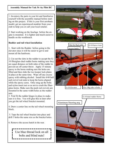
Assembly Manual for Yak 54 -by Pilot RC 1. Inventory the parts in your kit and familiarize yourself with the assembly manual before starting on this project. If this is your first aerobatic model, get an experienced modeler from your club to help you or call your local retailer. 2. Start working on the fuselage before the engine is mounted. It is lighter and much easier to handle on the workbench. Rudder and tail wheel installation 1. Start with the Rudder before going to the elevator since it will be easier to get to and mount all the hardware. 2. Cut out the slots in the rudder to accept the G- 10 fiberglass dual rudder horns making sure they are equal distance on both sides of the rudder to prevent an off center throw. Apply 15 minute epoxy to the horns making sure the holes are filled and then slide the two keeper lock plates in place at the same time. Wipe off any excess epoxy with rubbing alcohol. Install the 4/40 ball and swivel rod ends to keep the horns aligned while the epoxy cures. Only snug up the bolts and nylon insert nut so as not to crush the fiberglass horns. Make sure the push rod swivels are mounted in the same width holes as the rudder arm. 3. Trial fit the rudder hinges in place to make sure it is free. You will glue this in later after you get the tail wheel bracket mounted. 4. Draw a center line on the tail wheel mounting block. 5. Tape the tail wheel bracket into place and drill 3 holes the same size as the bracket holes. 6. Remove the access hatch in the rear. Use blue thread lock on all bolts and blind nuts! Slot for Rud cable Access hatch G-10 Elevator Aluminum Steering peg G-10 Servo Arm Elev Mtg tabs w/bolts G-10 dual rudder Horns Mounting Screws CL
- Page 2 and 3: 7. Now drill out the holes with the
- Page 4 and 5: 2. Remove the wheel collars from th
- Page 6 and 7: 5. Now you need to decide if you ar
- Page 8 and 9: Control Throws 1. After you set the
- Page 10: Hardware items included in kit: 1.
Assembly <strong>Manual</strong> for Yak 54 -by <strong>Pilot</strong> <strong>RC</strong><br />
1. Inventory the parts in your kit and familiarize<br />
yourself with the assembly manual before starting<br />
on this project. If this is your first aerobatic<br />
model, get an experienced modeler from your<br />
club to help you or call your local retailer.<br />
2. Start working on the fuselage before the engine<br />
is mounted. It is lighter and much easier to<br />
handle on the workbench.<br />
Rudder and tail wheel installation<br />
1. Start with the Rudder before going to the<br />
elevator since it will be easier to get to and<br />
mount all the hardware.<br />
2. Cut out the slots in the rudder to accept the G-<br />
10 fiberglass dual rudder horns making sure they<br />
are equal distance on both sides of the rudder to<br />
prevent an off center throw. Apply 15 minute<br />
epoxy to the horns making sure the holes are<br />
filled and then slide the two keeper lock plates<br />
in place at the same time. Wipe off any excess<br />
epoxy with rubbing alcohol. <strong>Install</strong> the 4/40 ball<br />
and swivel rod ends to keep the horns aligned<br />
while the epoxy cures. Only snug up the bolts<br />
and nylon insert nut so as not to crush the fiberglass<br />
horns. Make sure the push rod swivels are<br />
mounted in the same width holes as the rudder<br />
arm.<br />
3. Trial fit the rudder hinges in place to make<br />
sure it is free. You will glue this in later after<br />
you get the tail wheel bracket mounted.<br />
4. Draw a center line on the tail wheel mounting<br />
block.<br />
5. Tape the tail wheel bracket into place and<br />
drill 3 holes the same size as the bracket holes.<br />
6. Remove the access hatch in the rear.<br />
Use blue thread lock on all<br />
bolts and blind nuts!<br />
Slot for Rud cable<br />
Access hatch<br />
G-10 Elevator<br />
Aluminum Steering peg<br />
G-10 Servo Arm<br />
Elev Mtg tabs w/bolts<br />
G-10 dual rudder Horns<br />
Mounting Screws CL
7. Now drill out the holes with the same size bit as the<br />
blind nuts.<br />
8. <strong>Install</strong> the blind nuts by using a large washer and the<br />
bolt to draw the blind nut into place.<br />
9. Now bolt the tail wheel bracket in place using blue<br />
lock tite on the threads. Use 4 screws to mount access<br />
hatch into place.<br />
10. Drill a hole slightly smaller than the aluminum<br />
steering/swivel peg in the center of the rudder about 2”<br />
from the hinge line, force into place with lots of 5 minute<br />
epoxy.<br />
11. Now glue the rudder in place but first use a tooth<br />
pick and put some Vaseline on the hinges to keep the<br />
epoxy from gluing the hinges shut.<br />
12. Use a thin metal artist paint spatula to make sure all<br />
the 15 minute epoxy gets into the hinge slots and coat<br />
the hinges on the lower one half so they will be coated<br />
evenly when pushing the rudder into place.<br />
13. Wipe off any excess epoxy that may have ozzed out<br />
during the rudder mounting process and stand the airplane<br />
on its nose while the epoxy cures.<br />
14. Remove the steering arm from the tail wheel and<br />
install it into the swivel peg. Use blue lock tite when<br />
reinstalling the tail wheel bracket making sure it is<br />
aligned straight with the rudder and fin.<br />
15. Mount the rudder steering arm on your favorite<br />
servo after mounting the 4/40 push rod ends with cable<br />
attachments.<br />
16. Mount the 160 oz/in or large torque rudder servo in<br />
place using servo screws.<br />
17. Cut two equal lengths of rudder steering cable provided.<br />
18. Attach the cable to the servo using the brass tubing<br />
and crimp them in place with crimping pliers.<br />
19. Cut away the UltraCoat from the servo mounts and<br />
the slot for the rudder control cables.<br />
20. Run the 36 “yellow nyrod inter tubing from Dubro's<br />
nyrod set in from the back of the fuselage through the<br />
slots provided for the steering cable. Push forward to<br />
the servo. While keep the tube in place, slide the steering<br />
cable inside the tube all the way. Pull out the yellow<br />
tube and there is your cable. Repeat for the other cable.<br />
21. Finger tighten both cable as tight as you can and<br />
then finish tightening using the turnbuckles. Check the<br />
throw to make sure nothing is rubbing and that a cable<br />
does not go slack at maximum throw.<br />
Bolt on tabs for Stab<br />
Rec w/servos plugged in.<br />
Rudder Servo with 3” Metal arm.<br />
Servo w/push rod<br />
Zip ties Foam wire<br />
Holder.<br />
2
Stab and Elevator <strong>Install</strong>ation<br />
1. <strong>Install</strong> the dual G-10 horns in place for the<br />
elevator horn before sliding the stab in place.<br />
2. Remove the UltraCoat from the mounting<br />
hole tabs and blind nuts in the fuselage.<br />
3. Screw the threaded push rod and swivel in<br />
place onto the elevator horn.<br />
4. Plug in a 24” servo wire extension and use a<br />
securing clip provided to make sure they don’t<br />
come unplugged in flight.<br />
5. Mount the elevator servo in place and pull<br />
the servo wire extension up toward the front.<br />
6. Attach the servo extension wire using foam<br />
wire holding brackets or zip ties to the formers<br />
along the sides of the fuse so they can’t interfere<br />
with the rudder control cables.<br />
7. Now mount the servo arm on to the elevator<br />
push rod before installing it on the servo so<br />
you can tighten the 4-40 nylon insert locking<br />
nut to the 4-40 mounting screw.<br />
8. Slide the stab on to the carbon fiber tube<br />
and attach to fuse using the bolts provided by<br />
adding lock washers and washer to the bolts.<br />
Use blue lock tite on the threads.<br />
9. Now install the servo arm to the servo after<br />
making sure the elevator is level with the stab<br />
with the servo is in dead center. Tape the elevator<br />
in place using blue painter’s masking<br />
tape. (Use your receiver & transmitter or<br />
servo driver to center the servo.)<br />
Gear & Wheel Pants installation<br />
1. <strong>Install</strong> the axles in place with a wrench and<br />
socket on the nylon insert lock nuts. Do not<br />
over tighten and crack the carbon fiber.<br />
G-10 Horns. Epoxy in place.<br />
Servo swivel clevis<br />
3
2. Remove the wheel collars from the axles.<br />
3. Trial fit the wheel pants and make sure there is room<br />
for the outside shoulder nut to fit. Use you dremel tool<br />
to remove any extra fiberglass. The Shoulder nut has to<br />
have one of the points up so as to match the triangle cut<br />
in the pants.<br />
4. Now make sure the wheel pants are mounted 90 degrees<br />
to the bottom of the gear and trail fit a wheel on<br />
the axle.<br />
5. Clamp pant into place and drill one hole first the<br />
same size and the holes in the gear and insert one bolt.<br />
Now drill the second hold in the wheel pant.<br />
6. Remove the wheel pant and drill the hole out bigger<br />
to accommodate the blind nuts.<br />
8. Draw the blind nuts into place using a large flat<br />
washer and Allen wrench on the bolt.<br />
8. Use thin Zap CA flowed around the blind nuts to secure<br />
them in place.<br />
9. Mark to inside and outside location of the wheel collars<br />
and make sure the wheel is in the center of the pant<br />
using a Sharpie felt tip. File a flat spot on the axles for<br />
the allan screws and mount the wheel on the axle using<br />
blue lock tite on the allan screws. Spin wheel to make<br />
use it is free but not to much play from side to side.<br />
10. <strong>Install</strong> the wheel pants with tipping them slightly to<br />
miss the end of the axle.<br />
11. Finally install the wheel pant using blue lock tite on<br />
the threads of the blots, but do not over tighten.<br />
12. Repeat the above process for the other wheel pant.<br />
13. Now install the blind nuts into the landing gear<br />
mount using the same washer drawing into place technique<br />
use earlier. Run some thin Zap CA around the<br />
blind nuts to secure in place.<br />
14. Bolt the landing gear in place and this will help you<br />
while working on the engine installation. (locktite blue)<br />
Wing and servo <strong>Install</strong>ation<br />
1. This is the fastest of all the installations.<br />
2. Cut out the slots for the G-10 aileron horns on the<br />
bottom only. The top ultra Coat will hold in the 15<br />
minute epoxy.<br />
3. <strong>Install</strong> the horns by coating them with epoxy and sliding<br />
them into place. Put the locking tab into place and<br />
wipe off an excess glue with rubbing alcohol.<br />
Wheel collar<br />
Axle on Carbon LG<br />
G-10 Servo arm<br />
Center wheel in pants<br />
Mounting bolts into blind<br />
Nuts inside pant.<br />
G-10 Dual control Horn<br />
4
4. <strong>Install</strong> the 4-40 push rod swivel to the horn to make<br />
sure the holes are aligned.<br />
5. Cut out the ultra Coat from the servo mounting<br />
holes. Note the servo position.<br />
6. Mount the 1” servo arm to the servo push rod end<br />
using a 4-40 bolt, lock nut and blue lock tite.<br />
7. Attach a 12” servo lead extension and secure in<br />
place using the servo plug clips provided.<br />
8. Use the string provided to pull the extension through<br />
the wing.<br />
9. Now you can screw the servo into place and mount<br />
the servo arm making sure it is 90 degrees to the aileron.<br />
Check the position of the aileron with the servo<br />
in dead center.<br />
10. Now mount the servo arm onto the servo making<br />
sure to tighten all bolts and using lock tite.<br />
11. Trial fit the wing tube and mount the wings making<br />
sure the wing mounting bolts align and will tighten.<br />
Now remove the wings.<br />
Engine installation<br />
( You need to decide now if you are going to<br />
use a canister muffler or standard pitts style<br />
that will go straight out the cowl! )<br />
1. Measure the length of the engine from the<br />
firewall mounts to the prop thrust washer for<br />
the proper distance allowing 1/4” to 1/2”<br />
from the edge of the cowl. Move if needed.<br />
2. Draw the engine center line and thrust line<br />
darker with a ball point. Note the 2 degree<br />
right thrust built into the firewall. The cowl<br />
is already built with this offset as well.<br />
3. Use the drill template if you are going to<br />
use a DA .50 or measure your engines mounting<br />
location. Remember the engine is<br />
mounted inverted.<br />
4. Determine where the throttle arm push rod<br />
is going to the firewall and drill a hole. If<br />
you are going to use a Nyrod, then make the<br />
hole the same size as the outsider red tube.<br />
Carve out cowl to fit your engine, spark plug cable and<br />
exhaust pipe<br />
Use silicone on exhaust joint.<br />
Tank over flow-<br />
tygon tubing.<br />
Canister muffler held in place<br />
with tie wrap.<br />
Tank overflow<br />
Flex header pipe going back to<br />
canister muffler.<br />
Halls sensor to electronic<br />
ignition system.<br />
5
5. Now you need to decide if you are going<br />
to use a manual or servo to operate the<br />
choke. Drill holes in firewall for chock operating<br />
wire.<br />
6. Remove the fuel tank and but leave<br />
Velcro tape in place.<br />
7. <strong>Install</strong> the engine and drill holes for the<br />
pushrods for the throttle and/or choke servos<br />
as shown in the pictures. You can use a<br />
commercial mounting bracket or servo tape<br />
only but seal the plywood with 5 minute epoxy<br />
or thin CA glue so servo tape will stick.<br />
8. <strong>Install</strong> the Nyrod and check for interference<br />
when both are operated.<br />
9. Reinstall fuel tank and make a hole in the<br />
firewall for the Engine fuel line. Reattach<br />
line to fuel Dot. Wait till later to determine<br />
where the outlet for the overflow line will<br />
go depending on your engine installation.<br />
Use 3/8” urethane foam under tank to prevent<br />
the gas from foaming due to vibration.<br />
Make sure there is clearance between the<br />
firewall and wing tube so the tank does not<br />
rub up against any structure. Mount as<br />
close to the CG as possible.<br />
10. You can now mount the kill switch for<br />
the ignition in the location hole provided on<br />
the right side of the firewall near the cowl.<br />
(The kill switch show is from MPI)<br />
11. <strong>Install</strong> the ignition module on the floor<br />
using 4-40 screws with blind nuts or washers<br />
and nylon lock nuts.<br />
12. Route the battery power cable and<br />
switch away from the 2.4 or standard 72<br />
Mhz receiver to avoid RF interference.<br />
13. Run the spark plug wire out the bottom<br />
of the tank tray mount and down to the engine.<br />
Align the shielded cable in the center<br />
of the engine and use a zip tie to hold in position<br />
so it will not rub against the cowl.<br />
Batteries can also be mount on the firewall or<br />
firewall engine mount if needed for proper CG!<br />
Nyrods for choke and throttle<br />
Foam behind tank<br />
Electronic ignitions system.<br />
Clip lock & zip tie<br />
Velcro Straps hold tank.<br />
MPI Kill Switch module<br />
Fuel over flow line<br />
6
14. Route the Halls Sensor cable and hold in place with a<br />
zip tie to the engine mount and lock the plugs together.<br />
15. Route the rest of the servo cables and extensions depending<br />
on the radio you have. You can mount the new<br />
small 2.4 receivers with servo tape or hot glue.<br />
16. You should be able to mount the batteries on the floor<br />
just to the rear off the wing tube as shown. Your balance<br />
at the CG will determine their final mounting location.<br />
17. <strong>Install</strong> the canister muffler in the cooling tunnel with a<br />
commercial muffler mount and a support in the front of<br />
the muffler made of 1/4” plywood using some silicon tubing<br />
for insulation form the heat using E-6000 glue.<br />
18. <strong>Install</strong> the flex tube header pipe by attaching it to the<br />
engine first and then bending it around the back of the engine<br />
and then man handling it back into the center with a<br />
reverse curve.<br />
19. Trial fit the pipe to the muffler and cut of the pipe<br />
once you have determined that it fits and will not fall out<br />
due to vibration.<br />
20. Push the muffler tightly into the header and then glue<br />
the muffler supports in place using a 3/8” square hard<br />
wood piece with 15 minute epoxy. Set aside to cure.<br />
21. Measure the center of the spark plug and make a pattern<br />
of the engine head shape with a card stock or file<br />
folder stiff cardboard to hold its shape. Trial fit to make<br />
sure there is a minimum of 3/8” around the engine cooling<br />
fins. Also cut out for clearance for the exhaust pipes for<br />
the muffler you have. Measure twice and cut once.<br />
22. Use a fiber cutting tool to rough cut the cowl and finish<br />
with a round sander making use all the corner are<br />
rounded and not sharp 90 degree angle that can split under<br />
vibration.<br />
23. Trial fit till the cowl is right and then install into position<br />
using the bolts. There are two that mount from the<br />
rear of the firewall on the top of the cowl and two that<br />
mount from the front of the cowl opening.<br />
24. Make an extension tool with brass tubing and the<br />
proper size ball driver on one end and the handle on the<br />
other end by cutting a standard ball driver in half.<br />
25. Use some small heat shrink tubing over the bolt as it is<br />
attached to the ball drive to held in place to install the<br />
bolts. Carry some extra heat shrink tubing to the field<br />
along with a small cricket lighter in case you have to reattach<br />
the cowl in the future by this same method.<br />
26. <strong>Install</strong> the Prop and spinner to the engine, attach the<br />
wings and check the CG, located at the wing tube, with<br />
the canopy in place. Move batteries around till level.<br />
Two batteries installed under the Velcro tank<br />
straps over 3/8” foam.<br />
Canister Muffler in cooling tunnel<br />
Muffler Mounting bracket with silicon insulators.<br />
Cowl Bolt<br />
Heat Shrink over the<br />
bolt & ball tool<br />
Throttle Servo with Nyrod.<br />
Brass tubing<br />
Handle<br />
Special Cowl Bolt <strong>Install</strong>ing<br />
Tool<br />
7
Control Throws<br />
1. After you set the control throws up and have a few flights under you belt, you can change the<br />
rates and amounts as well as moving the CG back at 1/4” intervals.<br />
Ailerons 30 Degrees on High rate / 12 Degrees low rate.<br />
Elevators 40 Degrees on High rate / 12 Deg. Low rate<br />
Rudder 45 degree High rate / 40 Degree low rate.<br />
2. Learn to use exponential of about 40 percent on your elevator to make great landings and not<br />
over control a highly aerobatic airplane. Use 70 percent exponential on High Rate!<br />
Final Flight Check<br />
1. Make sure you have the right model programmed into your transmitter.<br />
2. Check the direction of each surface not and also right before you take off.<br />
3. Recheck all screws, horns and linkages for slop.<br />
4. Remember nothing wrong on the ground ever improves in the air!<br />
5. Check the airplane with the engine running and do a range check with your body between you<br />
and the plane at 150 feet. Check your battery voltage after each flight in case one servo is<br />
draining your battery pack.<br />
6. Recheck all screws, horns and linkages for slop after your maiden flight and check for damage<br />
if you made a bad landing you first time.<br />
7. Have an experienced pilot fly it for you the first time if you have any doubts in your mind<br />
about the maiden flight.<br />
8. Take a break after you first flight and let the adrenaline burned off by bragging to your fellow<br />
members how good it flies.<br />
9. Fly low and at a medium speed on your first few flight.<br />
10. Be sure the engine is right all the way through the run up to idle with no cough of hesitation in<br />
between.<br />
11. Listen to your engine run and have an observer with you to remember what you talked about<br />
during the flight or if you get into trouble. Always balance your props, vibration is a killer.<br />
12. Remember nose heavy airplanes fly all the time, tail heavy airplanes fly only once. Be on the<br />
CG!<br />
13. Fly 3D two mistakes high in the beginning and not close to people, planes or runways. Being<br />
a center of the runway hog does not endear you to many modelers.<br />
Conclusion:<br />
We at <strong>Pilot</strong> <strong>RC</strong> stand ready to answer any and all question about your Yak 54. Let<br />
us know how we can help you enjoy flying your Yak by emailing us or calling us<br />
with your questions.<br />
8
Safety Precautions<br />
This is not a Toy! This R/C ARF kit and the model you build from this kit is not<br />
a Toy!<br />
It is capable of serious bodily harm and property damage. It is YOUR responsibility as<br />
your alone to assemble correctly, properly installing all R/C components and fling gear<br />
(engine, tank, radio, pushrods, etc. and to test the model and fly it only with experienced,<br />
competent help from an experienced pilot using commonsense and in accordance<br />
with national and international safety standards as set forth by many Model Airplane<br />
Associations. It is suggested that you join such an organization and adhere to<br />
there rule for safety of fellow pilots. If you are just starting in R/C this in not the plane<br />
for you to learn how to fly. This is not a beginners airplane but designed for advance<br />
pilots who know aerobatics. If you need help contact a local hobby shop and purchase<br />
a trainer. Join a model airplane club in your area and take lessons from a veteran R/C<br />
flight instructor.<br />
Limits Of Responsibility: We accept no responsibility for crash damage. It is impossible to<br />
determine for certain whether crash damage was the result of a radio system failure or pilot error.<br />
We accept no responsibility for crash damage occurring during the use of a radio controlled<br />
model. We accept no responsibility for improper installation of our products.<br />
Disclaimer and Limitation of Liability as to Products Sold<br />
All <strong>Pilot</strong> <strong>RC</strong> products are guaranteed against defects for the period of 30 days. EXCEPT AS<br />
EXPRESSLY STATED HEREIN, <strong>Pilot</strong> <strong>RC</strong> makes no representations or warranties, either express<br />
or implied, of any kind with respect to products sold on the <strong>Pilot</strong> <strong>RC</strong> site. EXCEPT AS<br />
EXPRESSLY STATED HEREIN, <strong>Pilot</strong> <strong>RC</strong> expressly disclaims all warranties, express or implied,<br />
of any kind with respect to products sold on this site, including but not limited to, merchantability<br />
and fitness for a particular purpose. By placing an order, you agree that the sole<br />
and exclusive maximum liability to <strong>Pilot</strong> <strong>RC</strong> arising from any product sold on the <strong>Pilot</strong> <strong>RC</strong><br />
sites shall be the price of the product ordered. In no event shall <strong>Pilot</strong> <strong>RC</strong>, its directors, officers,<br />
employees and representatives be liable for special, indirect, consequential, or punitive damages<br />
related to product sold.<br />
Except in respect of death or personal injury caused by <strong>Pilot</strong> <strong>RC</strong>\'s negligence, under no circumstances<br />
whatsoever shall <strong>Pilot</strong> <strong>RC</strong>. be liable to the buyer for any loss or damage whatsoever<br />
(including but not limited to loss of profit or the loss of any other form of financial or nonfinancial<br />
benefit; loss of use of or damage to any property; work stoppage; any special, indirect,<br />
incidental or consequential loss or damage; costs; expenses; and other claims for compensation),<br />
arising out of or in connection with the sale of any <strong>Pilot</strong> <strong>RC</strong>. product (including any misrepresentation<br />
(unless fraudulent); any breach of an implied or express warranty, condition or<br />
other term; or any breach of a common law duty), in an amount exceeding the price of the <strong>Pilot</strong><br />
<strong>RC</strong>. product giving rise to the claim, except as expressly agreed in writing by <strong>Pilot</strong> <strong>RC</strong>.<br />
9
Hardware items included in kit:<br />
1. Push Rods, threaded ends with bolts for Ailerons, Elevators and<br />
Rudder.<br />
2. Mounting bolts and washers for Stabilizer.<br />
3. G-10 Control Horns.<br />
4. G-10 Servo arms.<br />
5. Mounting bolts for canopy.<br />
6. Nylon bolts for attaching wing.<br />
7. Carbon fiber Tail wheel assembly with aluminum steering peg.<br />
8. Carbon fiber landing gear and spinner.<br />
9. Bolts and blind nuts for mounting landing gear.<br />
10.Axles, wheel collars, wheel pant attaching screws with blind nuts.<br />
11.Wheels.<br />
12.Hinges (installed)<br />
13.Servo plug security clips.<br />
14. Rudder steering cable, brass tube cable crimps & cable swivel<br />
turnbuckles.<br />
15. Tank with Fuel Dot and Tygon tubing. (<strong>Install</strong>ed)<br />
Items you need to buy:<br />
1. Engine with muffler (50-60 CC)<br />
2. Propeller to suit engine.<br />
3. 6 channel Transmitter, Receiver and Servos.<br />
4. Batteries.<br />
5. Servo Extension wires.<br />
6. Switch.<br />
7. Kill Switch.<br />
8. Tie wraps.<br />
9. Foam wire holders.<br />
10. Additional washers.<br />
11. Foam rubber.<br />
12. Servo tape.<br />
13. NyRods.<br />
14. Push rod quick connects.<br />
15. <strong>Pilot</strong> and instrument panel.<br />
10


