Reflex RB95 motorised blockout roller blind - Clever Home Automation
Reflex RB95 motorised blockout roller blind - Clever Home Automation
Reflex RB95 motorised blockout roller blind - Clever Home Automation

You also want an ePaper? Increase the reach of your titles
YUMPU automatically turns print PDFs into web optimized ePapers that Google loves.
REFLEX TM<br />
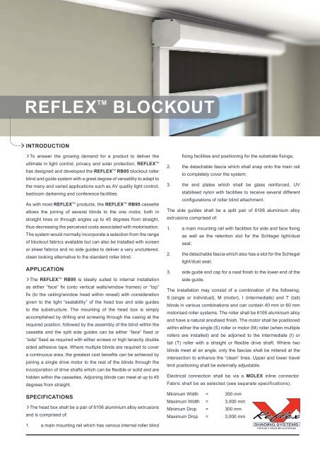
INTRODUCTION<br />
> To answer the growing demand for a product to deliver the<br />
ultimate in light control, privacy and solar protection, REFLEX TM<br />
has designed and developed the REFLEX TM <strong>RB95</strong> <strong>blockout</strong> <strong>roller</strong><br />
<strong>blind</strong> and guide system with a great degree of versatility to adapt to<br />
the many and varied applications such as AV quality light control,<br />
bedroom darkening and conference facilities.<br />
As with most REFLEX TM products, the REFLEX TM <strong>RB95</strong> cassette<br />
allows the joining of several <strong>blind</strong>s to the one motor, both in<br />
straight lines or through angles up to 45 degrees from straight,<br />
thus decreasing the perceived costs associated with motorisation.<br />
The system would normally incorporate a selection from the range<br />
of <strong>blockout</strong> fabrics available but can also be installed with screen<br />
or sheer fabrics and no side guides to deliver a very uncluttered,<br />
clean looking alternative to the standard <strong>roller</strong> <strong>blind</strong>.<br />
APPLICATION<br />
> The REFLEX TM <strong>RB95</strong> is ideally suited to internal installation<br />
as either “face” fix (onto vertical walls/window frames) or “top”<br />
fix (to the ceiling/window head within reveal) with consideration<br />
given to the light “sealability” of the head box and side guides<br />
to the substructure. The mounting of the head box is simply<br />
accomplished by drilling and screwing through the casing at the<br />
required position, followed by the assembly of the <strong>blind</strong> within the<br />
cassette and the split side guides can be either “face” fixed or<br />
“side” fixed as required with either screws or high tenacity double<br />
sided adhesive tape. Where multiple <strong>blind</strong>s are required to cover<br />
a continuous area, the greatest cost benefits can be achieved by<br />
joining a single drive motor to the rest of the <strong>blind</strong>s through the<br />
incorporation of drive shafts which can be flexible or solid and are<br />
hidden within the cassettes. Adjoining <strong>blind</strong>s can meet at up to 45<br />
degrees from straight.<br />
SPECIFICATIONS<br />
> The head box shall be a pair of 6106 aluminium alloy extrusions<br />
and is comprised of:<br />
1. a main mounting rail which has various internal <strong>roller</strong> <strong>blind</strong><br />
BLOCKOUT<br />
fixing facilities and positioning for the substrate fixings;<br />
2. the detachable fascia which shall snap onto the main rail<br />
to completely cover the system;<br />
3. the end plates which shall be glass reinforced, UV<br />
stabilised nylon with facilities to receive several different<br />
configurations of <strong>roller</strong> <strong>blind</strong> attachment.<br />
The side guides shall be a split pair of 6106 aluminium alloy<br />
extrusions comprised of:<br />
1. a main mounting rail with facilities for side and face fixing<br />
as well as the retention slot for the Schlegel light/dust<br />
seal;<br />
2. the detachable fascia which also has a slot for the Schlegel<br />
light/dust seal;<br />
3. side guide end cap for a neat finish to the lower end of the<br />
side guide.<br />
The installation may consist of a combination of the following;<br />
S (single or individual), M (motor), I (intermediate) and T (tail)<br />
<strong>blind</strong>s in various combinations and can contain 40 mm or 60 mm<br />
<strong>motorised</strong> <strong>roller</strong> systems. The <strong>roller</strong> shall be 6106 aluminium alloy<br />
and have a natural anodised finish. The motor shall be positioned<br />
within either the single (S) <strong>roller</strong> or motor (M) <strong>roller</strong> (when multiple<br />
<strong>roller</strong>s are installed) and be adjoined to the intermediate (I) or<br />
tail (T) <strong>roller</strong> with a straight or flexible drive shaft. Where two<br />
<strong>blind</strong>s meet at an angle, only the fascias shall be mitered at the<br />
intersection to enhance the “clean” lines. Upper and lower travel<br />
limit positioning shall be externally adjustable.<br />
Electrical connection shall be via a MOLEX inline connector.<br />
Fabric shall be as selected (see separate specifications).<br />
Minimum Width = 350 mm<br />
Maximum Width = 3,000 mm<br />
Minimum Drop = 300 mm<br />
Maximum Drop = 3,000 mm
REFLEX TM<br />
<strong>RB95</strong> SYSTEM EXPLODED<br />
1<br />
2<br />
3<br />
4<br />
9<br />
5<br />
X<br />
6<br />
10<br />
11<br />
7<br />
12<br />
BLOCKOUT<br />
13<br />
Y<br />
TOP FIX ARRANGEMENT FACE FIX ARRANGEMENT<br />
14<br />
<strong>RB95</strong><br />
X = 96<br />
Y = 105<br />
8<br />
19<br />
18<br />
17<br />
16<br />
15<br />
21<br />
20<br />
SHADING SYSTEMS OF AUSTRALIA<br />
F9 / 1-7 Canterbury Rd<br />
Braeside Victoria 3195 Australia<br />
www.shadingsystems.com<br />
22<br />
X<br />
ITEM DESCRIPTION<br />
1. END CAP INFILL<br />
2. END COVER SCREW<br />
3. END CAP LHS<br />
4. HEADBOX COVER - BACK<br />
5. BACK BRACKET GRUB SCREW<br />
6. BACK BRACKET<br />
7. BRACKET MOUNTING SCREW<br />
8. END CAP RHS<br />
9. ROLLER TUBE<br />
10. MOTOR FIXING SCREW<br />
11. MOTOR CROWN<br />
12. MOTOR<br />
13. <strong>RB95</strong> BASE RAIL<br />
14. SPLINE<br />
15. BASERAIL END CAP<br />
16. RIVET<br />
17. MOTOR WHEEL<br />
18. HEADBOX COVER - FRONT<br />
19. SIDE GUIDE - BACK<br />
20. SIDE GUIDE END CAP<br />
21. SIDE GUIDE END SCREW<br />
22. SIDE GUIDE - FRONT<br />
Ph: + 61 3 9588 1200<br />
Fx: + 61 3 9588 1233<br />
sales@shadingsystems.com<br />
Y