Installation Intructions and Template for 5K Locks - Best Access ...
Installation Intructions and Template for 5K Locks - Best Access ...
Installation Intructions and Template for 5K Locks - Best Access ...

You also want an ePaper? Increase the reach of your titles
YUMPU automatically turns print PDFs into web optimized ePapers that Google loves.
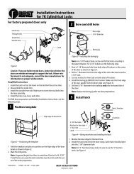
6 Remove inside lever <strong>and</strong> trim<br />
1 Insert the pick tool into the lever keeper hole <strong>and</strong> depress the<br />
keeper. Slide the lever off. See Figure 6.<br />
Lever keeper<br />
hole<br />
Pick tool<br />
Figure 6 Removing the inside lever<br />
2 Holding the inside rose assembly as shown in Figure 7, remove the<br />
rose from the rose liner.<br />
Figure 7 Removing the inside rose from the liner<br />
7 Install inside lever assembly<br />
1 Mount the inside rose liner <strong>and</strong> sleeve assembly by screwing the<br />
two screws into the outside studs as shown in Figure 8.<br />
Studs<br />
Push down here<br />
Push up here<br />
Inside rose liner<br />
<strong>and</strong> sleeve assembly<br />
Stud screws<br />
Rose<br />
Align hole in rose<br />
with latch<br />
Align stud with the<br />
latch<br />
Latch<br />
Figure 8 Installing the inside rose <strong>and</strong> sleeve assembly with screws<br />
2 Align the hole in the rose with the latch as shown <strong>and</strong> push the<br />
rose onto the rose liner. Make sure that the rose fits snugly.<br />
3 Push the inside lever onto the sleeve until it snaps in place.<br />
8 Install key-in-knob cylinder<br />
or interchangeable (IC) core<br />
For key-in-knob cylinders (non-interchangeable cores)<br />
1 Remove the outside lever. Do this by turning the lever down,<br />
depressing the exposed lever keeper with the pick tool <strong>and</strong> then<br />
pulling the lever off. See Figure 9.<br />
Tip: Putting the pick tool on like you would a ring <strong>and</strong> then using it<br />
may make removing the h<strong>and</strong>le easier. This frees your fingers to<br />
grasp the h<strong>and</strong>le.<br />
Pick tool<br />
Turn lever to<br />
expose the<br />
lever keeper<br />
Figure 9 Removing the outside non-IC lever<br />
2 Remove the lever insert.<br />
3 Disassemble the key-in-knob cylinder.<br />
4 Discard the nut that is removed from the cylinder <strong>and</strong> use the nut<br />
that comes with the cap <strong>and</strong> end caps. You must use the correct<br />
nut <strong>for</strong> the cylinder to operate properly. See Figure 10.<br />
5 Assemble the key-in-knob cylinder as shown in Figure 10.<br />
Tip: Push down on the end cap while screwing the nut on.<br />
Orient the end<br />
cap as shown<br />
You will have one<br />
or the other, not<br />
both<br />
Figure 10 Assembling the key-in-knob cylinder<br />
6 Install the cylinder into the lever.<br />
7 Reinstall the lever insert.<br />
8 Reinstall the lever. Make sure that the key is in the<br />
horizontal position.<br />
For interchangeable cores<br />
1 Insert the throw member into the back of the core. See Figure 11.<br />
Note: Use the 6-pin spacer spring only with 6-pin cores.<br />
BEST ACCESS SYSTEMS<br />
a Division of Stanley Security Solutions, Inc<br />
Cap<br />
Nut<br />
Note: This nut<br />
is taller than<br />
the nut that is<br />
part of the<br />
existing cylinder.<br />
Interchangeable<br />
core<br />
6-pin spacer<br />
spring<br />
Use the spacer<br />
only <strong>for</strong> 6-pin<br />
cores<br />
Throw member<br />
Figure 11 Assembling the interchangeable core <strong>and</strong> throw member<br />
2 Put the control key into the core <strong>and</strong> turn the key 15 degrees<br />
clockwise.<br />
3 Put the core <strong>and</strong> throw member into the lever with the control<br />
key.<br />
4 Turn the key 15 degrees counterclockwise <strong>and</strong> remove the key.<br />
Caution: Since the control key is a high-security key, make<br />
sure to keep it protected.<br />
9 Check lock operation<br />
To unlock with key<br />
■ Insert an operating key into the lock <strong>and</strong> turn the key<br />
counterclockwise.<br />
To lock with key<br />
■ Insert an operating key into the lock <strong>and</strong> turn the key clockwise.<br />
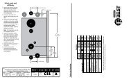
2 15/32" (63 mm)<br />
Drill 2 1/8"<br />
(54 mm)<br />
dia hole<br />
<strong>Template</strong> <strong>for</strong> <strong>5K</strong> Lock<br />
Fold along the<br />
dashed line <strong>and</strong><br />
place on the<br />
high edge of<br />
door bevel<br />
Door thicknesses<br />
1 3/4" 1 3/8"<br />
(45mm) (35mm)<br />
5/32" (4mm)<br />
3/32" (3mm)<br />
deep<br />
Drill<br />
1" (25<br />
mm)<br />
hole<br />
T81176/Rev A 1911879 ER-7991-44 April 2006<br />
2 3/8" BACKSET (60 mm)<br />
2 3/4" BACKSET (70 mm)<br />
<br />
Door edge centerline<br />
(based on door<br />
thickness)


![B.A.S.I.S. G Service Manual [T63300] - Best Access Systems](https://img.yumpu.com/48375082/1/190x245/basis-g-service-manual-t63300-best-access-systems.jpg?quality=85)