Installation Intructions and Template for 5K Locks - Best Access ...
Installation Intructions and Template for 5K Locks - Best Access ...
Installation Intructions and Template for 5K Locks - Best Access ...

You also want an ePaper? Increase the reach of your titles
YUMPU automatically turns print PDFs into web optimized ePapers that Google loves.
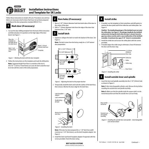
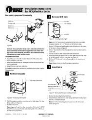
Follow these instructions to install a <strong>5K</strong> Lock. Procedures one <strong>and</strong> two<br />
below are necessary only <strong>for</strong> doors that have not yet been prepared<br />
according to the door preparation st<strong>and</strong>ard ANSI A115.2.<br />
1 Mark door (if necessary)<br />
1 Cut out the door drilling template from the back of this instruction<br />
<strong>and</strong> fold <strong>and</strong> place it in position on the high edge of the door<br />
bevel. See Figure 1.<br />
Place the<br />
template on<br />
the high side of<br />
the door bevel<br />
Mark 1 inch<br />
(25mm) hole<br />
here<br />
Figure 1 Marking the door with the door template<br />
<strong>Installation</strong> Instructions<br />
<strong>and</strong> <strong>Template</strong> <strong>for</strong> <strong>5K</strong> <strong>Locks</strong><br />
Mark 2 1/8 inch<br />
(54mm) hole here<br />
<strong>Template</strong><br />
2 Follow the instructions on the template <strong>and</strong> mark the drill points.<br />
Note: Suggested height from floor to centerline of the lock is<br />
40 5/16″ (1.024 m). If steel frames are used, the latch centerline must<br />
be in line with the center of the strike preparation.<br />
2 Bore holes (if necessary)<br />
1 Bore a 2 1/8″ (54mm) diameter hole from both sides of the door to<br />
the center of the door.<br />
2 Drill a 1″ (25mm) diameter hole from the edge of the door that<br />
intersects the 2 1/8″ hole.<br />
3 Install latch<br />
1 Exp<strong>and</strong> or collapse the latch to match the backset of the door. See<br />
Figure 2.<br />
Note: The latch comes from the factory ready <strong>for</strong> a 2 3/8” backset<br />
door preparation.<br />
2 3/4" (70mm)<br />
2 3/8" (60mm)<br />
Push together<br />
<strong>for</strong> 2 3/8”<br />
backset<br />
Pull apart<br />
<strong>for</strong> 2 3/4”<br />
backset<br />
Figure 2 Adjusting the latch to the proper backset<br />
2 Temporarily install the latch <strong>and</strong> mark the outline of the latch face,<br />
then remove. Mortise the door edge <strong>for</strong> the latch face.<br />
Latch faceplate<br />
adapter<br />
Latch<br />
Deadlocking<br />
plunger<br />
Mortise <strong>for</strong> the<br />
latch face<br />
Figure 3 Installing the latch<br />
Note: If the door has been prepared <strong>for</strong> a 1 1/8” latch face width<br />
(common on 1 3/4” thick doors), use the latch faceplate adapter. See<br />
Figure 3.<br />
3 Install the latch (<strong>and</strong> latch faceplate adapter if required) with the<br />
screws provided. Check the door swing.<br />
BEST ACCESS SYSTEMS<br />
a Division of Stanley Security Solutions, Inc<br />
4 Install strike<br />
1 If needed, use the template to find centerlines <strong>and</strong> drill points to<br />
mortise the door jamb <strong>and</strong> fit the strike box <strong>and</strong> strike plate. See<br />
Figure 4.<br />
Caution: The deadlocking plunger of the latchbolt must not enter<br />
the strike plate. See Figure 3. The plunger deadlocks the latchbolt<br />
<strong>and</strong> prevents <strong>for</strong>cing the latch when the door is closed. Excessive<br />
gap may reduce security <strong>and</strong>/or cause malfunction of the latchbolt<br />
assembly. A maximum door gap of 1/8″ (3mm) is recommended.<br />
2 Install the strike box <strong>and</strong> secure the strike plate with the screws<br />
provided.<br />
3 If needed adjust the strike tang to eliminate a loose fit between<br />
the door <strong>and</strong> the door stop.<br />
Figure 4 Installing the strike<br />
1/2 of door<br />
thickness<br />
Door stop<br />
Strike box<br />
Strike<br />
Strike tang<br />
Door frame<br />
5 Install outside lever <strong>and</strong> spindle<br />
1 Insert the lever <strong>and</strong> spindle assembly into the 2 1/8” (63mm) hole<br />
as shown in Figure 5.<br />
Note 1: Non-interchangeable cylinders only: Remove the key be<strong>for</strong>e<br />
installing the outside lever <strong>and</strong> spindle assembly.<br />
Note 2: Make sure that the spindle inside the square shaft is in the<br />
horizontal position <strong>and</strong> that the outside lever can turn freely.<br />
Keep spindle<br />
horizontal<br />
Outside lever<br />
<strong>and</strong> spindle<br />
assembly<br />
Figure 5 Installing the outside lever <strong>and</strong> spindle – interchangeable<br />
core version shown<br />
T81176/Rev A 1911879 ER-7991-44 April 2006 Continued —
6 Remove inside lever <strong>and</strong> trim<br />
1 Insert the pick tool into the lever keeper hole <strong>and</strong> depress the<br />
keeper. Slide the lever off. See Figure 6.<br />
Lever keeper<br />
hole<br />
Pick tool<br />
Figure 6 Removing the inside lever<br />
2 Holding the inside rose assembly as shown in Figure 7, remove the<br />
rose from the rose liner.<br />
Figure 7 Removing the inside rose from the liner<br />
7 Install inside lever assembly<br />
1 Mount the inside rose liner <strong>and</strong> sleeve assembly by screwing the<br />
two screws into the outside studs as shown in Figure 8.<br />
Studs<br />
Push down here<br />
Push up here<br />
Inside rose liner<br />
<strong>and</strong> sleeve assembly<br />
Stud screws<br />
Rose<br />
Align hole in rose<br />
with latch<br />
Align stud with the<br />
latch<br />
Latch<br />
Figure 8 Installing the inside rose <strong>and</strong> sleeve assembly with screws<br />
2 Align the hole in the rose with the latch as shown <strong>and</strong> push the<br />
rose onto the rose liner. Make sure that the rose fits snugly.<br />
3 Push the inside lever onto the sleeve until it snaps in place.<br />
8 Install key-in-knob cylinder<br />
or interchangeable (IC) core<br />
For key-in-knob cylinders (non-interchangeable cores)<br />
1 Remove the outside lever. Do this by turning the lever down,<br />
depressing the exposed lever keeper with the pick tool <strong>and</strong> then<br />
pulling the lever off. See Figure 9.<br />
Tip: Putting the pick tool on like you would a ring <strong>and</strong> then using it<br />
may make removing the h<strong>and</strong>le easier. This frees your fingers to<br />
grasp the h<strong>and</strong>le.<br />
Pick tool<br />
Turn lever to<br />
expose the<br />
lever keeper<br />
Figure 9 Removing the outside non-IC lever<br />
2 Remove the lever insert.<br />
3 Disassemble the key-in-knob cylinder.<br />
4 Discard the nut that is removed from the cylinder <strong>and</strong> use the nut<br />
that comes with the cap <strong>and</strong> end caps. You must use the correct<br />
nut <strong>for</strong> the cylinder to operate properly. See Figure 10.<br />
5 Assemble the key-in-knob cylinder as shown in Figure 10.<br />
Tip: Push down on the end cap while screwing the nut on.<br />
Orient the end<br />
cap as shown<br />
You will have one<br />
or the other, not<br />
both<br />
Figure 10 Assembling the key-in-knob cylinder<br />
6 Install the cylinder into the lever.<br />
7 Reinstall the lever insert.<br />
8 Reinstall the lever. Make sure that the key is in the<br />
horizontal position.<br />
For interchangeable cores<br />
1 Insert the throw member into the back of the core. See Figure 11.<br />
Note: Use the 6-pin spacer spring only with 6-pin cores.<br />
BEST ACCESS SYSTEMS<br />
a Division of Stanley Security Solutions, Inc<br />
Cap<br />
Nut<br />
Note: This nut<br />
is taller than<br />
the nut that is<br />
part of the<br />
existing cylinder.<br />
Interchangeable<br />
core<br />
6-pin spacer<br />
spring<br />
Use the spacer<br />
only <strong>for</strong> 6-pin<br />
cores<br />
Throw member<br />
Figure 11 Assembling the interchangeable core <strong>and</strong> throw member<br />
2 Put the control key into the core <strong>and</strong> turn the key 15 degrees<br />
clockwise.<br />
3 Put the core <strong>and</strong> throw member into the lever with the control<br />
key.<br />
4 Turn the key 15 degrees counterclockwise <strong>and</strong> remove the key.<br />
Caution: Since the control key is a high-security key, make<br />
sure to keep it protected.<br />
9 Check lock operation<br />
To unlock with key<br />
■ Insert an operating key into the lock <strong>and</strong> turn the key<br />
counterclockwise.<br />
To lock with key<br />
■ Insert an operating key into the lock <strong>and</strong> turn the key clockwise.<br />
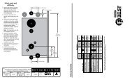
2 15/32" (63 mm)<br />
Drill 2 1/8"<br />
(54 mm)<br />
dia hole<br />
<strong>Template</strong> <strong>for</strong> <strong>5K</strong> Lock<br />
Fold along the<br />
dashed line <strong>and</strong><br />
place on the<br />
high edge of<br />
door bevel<br />
Door thicknesses<br />
1 3/4" 1 3/8"<br />
(45mm) (35mm)<br />
5/32" (4mm)<br />
3/32" (3mm)<br />
deep<br />
Drill<br />
1" (25<br />
mm)<br />
hole<br />
T81176/Rev A 1911879 ER-7991-44 April 2006<br />
2 3/8" BACKSET (60 mm)<br />
2 3/4" BACKSET (70 mm)<br />
<br />
Door edge centerline<br />
(based on door<br />
thickness)


![B.A.S.I.S. G Service Manual [T63300] - Best Access Systems](https://img.yumpu.com/48375082/1/190x245/basis-g-service-manual-t63300-best-access-systems.jpg?quality=85)