Chapter 6 - NEWELS - WM Coffman
Chapter 6 - NEWELS - WM Coffman
Chapter 6 - NEWELS - WM Coffman

You also want an ePaper? Increase the reach of your titles
YUMPU automatically turns print PDFs into web optimized ePapers that Google loves.
6-1<br />
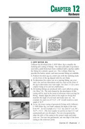
CHAPTER 6<br />
Newel Installation<br />
Proper newel<br />
installation is critical to<br />
ensuring a correctly<br />
built, code compliant<br />
staircase. Height of the<br />
installed newels<br />
determines both the rake<br />
and balcony rail heights,<br />
while secure installation<br />
and proper placement<br />
will be the main<br />
determining factors in<br />
overall balustrade<br />
strength. Newels should<br />
be placed at the top and<br />
bottom of every stair, at<br />
all directional changes,<br />
and no further apart<br />
than 8' on straight<br />
sections of balcony<br />
level rail.<br />
All newels should be<br />
installed with the use of<br />
construction adhesive or<br />
carpenter’s glue. Refer to<br />
<strong>Chapter</strong> 2 for more<br />
information concerning<br />
newels and their uses.<br />
C O F F M A N S T A I R P A R T S • S I N C E 1 8 7 4 CHAPTER 6 - NEWEL INSTALLATION 1
TRIM TEMPLATE<br />
BASED ON<br />
BALUSTER SIZE<br />
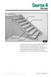
OTP STARTING NEWEL LAYOUT<br />
For most Over-the-Post applications using turnouts or volutes, a C-8010 single end or C-8015<br />
double end bullnose starting step will be required.<br />
A template provided with all starting fittings will mark proper placement of the newel on the<br />
bullnose starting step. For standard center line placement (See Photo 5-1) trim template<br />
according to baluster size used and place on top of prefitted starting step with the notch<br />
around the riser/skirtboard corner. PHOTO 6-2. Mark newel center point with a nail punch<br />
or awl. Baluster center points can also be marked at this time. PHOTO 6-3.<br />
TRIM TEMPLATE TO ALIGN WITH<br />
ALTERNATIVE CENTER LINE<br />
NOTE: If center line has been moved for any reason (See <strong>Chapter</strong> 5, Page 5) the template will<br />
have to be adjusted by trimming the edge adjacent to the skirtboard until the center line on<br />
the template lines up with the adjusted center line on your stair. PHOTO 6-4.<br />
2 CHAPTER 6 - NEWEL INSTALLATION<br />
6-2<br />
STANDARD<br />
CENTER LINE<br />
ALTERNATIVE<br />
CENTER LINE<br />
PLACE TEMPLATE AROUND<br />
RISER/SKIRTBOARD CORNER<br />
MARK NEWEL AND<br />
BALUSTER CENTER<br />
POINTS<br />
6-3<br />
6-4<br />
C O F F M A N S T A I R P A R T S • S I N C E 1 8 7 4
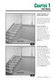
OTP STARTING NEWEL HEIGHTS<br />
(For a 34" Rake Rail Height)<br />
STARTING EASING<br />
TURNOUT<br />
VOLUTE<br />
ASCENDING<br />
VOLUTE<br />
STARTING FITTING NET MEASUREMENT<br />
VERTICAL VOLUTE<br />
36-1/2"<br />
40-1/2"<br />
STARTING NEWEL<br />
INSTALLATION<br />
The main determining factor<br />
in the rake rail height<br />
achieved is the height (in<br />
correlation to the placement) of<br />
the installed starting newel.<br />
Before installing any<br />
starting newel, be sure that<br />
the height of your newel<br />
will work for the rake rail<br />
height that you wish to<br />
achieve. CHART 6-5<br />
summarizes newel lengths<br />
for a 34" rake rail height<br />
(See Chart 2-58). Refer to<br />
<strong>Chapter</strong> 2, Pages 14-19 for<br />
more complete information<br />
on correct newel placement<br />
and requirements for rail<br />
height adjustments.<br />
NOTE: Newels are laminated<br />
and therefore have two solid<br />
faces and two faces with glue<br />
lines. We recommend you<br />
turn the newel in order that<br />
the solid faces are directed in<br />
the most visible directions.<br />
C O F F M A N S T A I R P A R T S • S I N C E 1 8 7 4 CHAPTER 6 - NEWEL INSTALLATION 3<br />
39"<br />
36"<br />
33-7/8"<br />
6-5
DOWELED<br />
OVER-THE-POST<br />
STARTING <strong>NEWELS</strong><br />
For doweled Over-the-Post<br />
newels installed in starting<br />
steps, start by prefitting the<br />
starting riser and tread to<br />
the stair. With the riser and<br />
tread in place, drill a 1-1/2"<br />
diameter hole through the<br />
starting tread and the upper<br />
riser core block at the<br />
marked location.<br />
PHOTO 6-6.<br />
TRIM 3/16"<br />
SHORT<br />
DRILL 1-1/2"<br />
DIAMETER HOLE<br />
4 CHAPTER 6 - NEWEL INSTALLATION<br />
UPPER<br />
CORE<br />
BLOCK<br />
LOWER<br />
CORE<br />
BLOCK<br />
C-8010 BULLNOSE<br />
STARTING STEP<br />
6-7 6-8<br />
C-3301 RAIL & POST<br />
FASTENER<br />
DRILL 1/4"<br />
DIAMETER HOLE<br />
Mark and trim the dowel on your starting newel to leave approximately 3/16" space between<br />
the dowel and lower core block. PHOTO 6-7. With newel placed in the step, drill a 1/4"<br />
diameter hole through the bottom of the lower core block into the center of the dowel<br />
approximately 3". Remove newel and re-bore the hole in the lower block to 3/8". Liberally<br />
apply construction adhesive and permanently attach starting step with a 5/16" x 3" <strong>Coffman</strong><br />
C-3301 Rail & Post Fastener (See <strong>Chapter</strong> 12, Page 4 for full instructions).<br />
PHOTO 6-8. For alternative installations, See Photo 6-27.<br />
6-6<br />
DRILL 3/8" DIAMETER<br />
HOLE<br />
C O F F M A N S T A I R P A R T S • S I N C E 1 8 7 4
6-10<br />
6-9<br />
ADJUSTABLE<br />
<strong>NEWELS</strong><br />
<strong>Coffman</strong>’s line of adjustable<br />
newels provides a starting<br />
newel with the flexibility to<br />
be used with both turnouts<br />
and volutes over a wide<br />
range of rake rail height<br />
requirements. These<br />
versatile newels are<br />
manufactured with a 1-1/2"<br />
diameter hole bored 10”<br />
deep into the bottom of the<br />
newel and have a 19" dowel<br />
shipped unattached.<br />
PHOTO 6-9.<br />
6-11<br />
Adjustable newels are available in all of <strong>Coffman</strong>’s Over-the-Post families and are easily<br />
identifiable in <strong>Coffman</strong> catalogs by the dotted line signifying the bored hole in the base.<br />
DRAWING 6-10. These newels allow a 4" range of cut for exact starting newel height<br />
adjustment in the field. Determine the exact height of the newel needed for your application<br />
(See Table 2-58), trim the newel, and apply dowel with construction adhesive and finish nails.<br />
PHOTO 6-11. Standard installation techniques outlined in <strong>Chapter</strong> 6, Page 4 are then applicable.<br />
C O F F M A N S T A I R P A R T S • S I N C E 1 8 7 4 CHAPTER 6 - NEWEL INSTALLATION 5
LAY OUT NEWEL<br />
LOCATION FROM<br />
CENTER POINT<br />
6 CHAPTER 6 - NEWEL INSTALLATION<br />
6-12 6-13<br />
UNDOWELED <strong>NEWELS</strong> ON STARTING STEPS<br />
Although <strong>Coffman</strong> recommends the use of starting newels with dowel bottoms, nondoweled,<br />
square bottom newels may be used if desired.<br />
Begin installation by prefitting and permanently installing the starting riser to the stair using<br />
standard installation procedures. The nondoweled, square bottomed newel will then have to<br />
be installed onto the starting tread. Locate the newel center point (See Photo 6-3), lay out the<br />
newel location, and drill three equally spaced 3/8” diameter holes through the tread in the<br />
newel location. PHOTO 6-12. Place the newel on top of the step in the required location and<br />
mark the location of one of the 3/8" holes on the bottom of the newel. Drill a 1/4" diameter<br />
pilot hole 3" deep into the newel at the marked location. Using carpenter’s glue on the bottom<br />
of the newel square, install a C-3301 Rail & Post Fastener into the predrilled hole. Pilot holes<br />
can then be drilled into the other 3/8" diameter holes and C-3301 Fasteners installed. PHOTO 6-13.<br />
NOTE: One disadvantage of<br />
a square bottom newel in a<br />
volute application is the<br />
closeness of the nearest<br />
baluster to the newel. This<br />
baluster will be less than<br />
1/4" from the starting newel<br />
if the traditional location<br />
provided on the template is<br />
used. Two options include<br />
the slight movement of this<br />
baluster from the template<br />
location or the removal of<br />
one baluster from under the<br />
volute (which will require a<br />
manual recentering of the<br />
remaining balusters).<br />
PHOTO 6-14.<br />
C-3301 RAIL & POST<br />
FASTENERS<br />
UNADJUSTED<br />
BALUSTER<br />
PLACEMENT WITH<br />
SQUARE BOTTOM<br />
<strong>NEWELS</strong><br />
6-14<br />
C O F F M A N S T A I R P A R T S • S I N C E 1 8 7 4
LAY OUT NEWEL<br />
LOCATION<br />
6-15<br />
6-17<br />
6-16<br />
NOTCHED STARTING <strong>NEWELS</strong> (OTP OR PTP)<br />
For Post-to-Post applications or Over-the-Post applications using starting easings, the<br />
traditionally correct placement of the starting newel will be with the center of the newel<br />
aligned directly above the face of the first riser (See Photo 5-8). This placement of the center<br />
line will require both a quarter-notched newel (See Page 6-13, Notching of Newels) as well as a<br />
notched cut into the tread overhang above the riser/skirtboard corner. Begin by transferring<br />
the center line of the stair to the front nosing of the first tread. Using a combination square,<br />
lay out the location of the newel. These lines will make the required cut lines for the notch<br />
on the tread overhang obvious. PHOTO 6-15. Cut with jigsaw and file to fit. PHOTO 6-16.<br />
TRIM BOTTOM OF<br />
NEWEL TO FIT<br />
TRANSFER<br />
BALUSTRADE<br />
CENTER LINE<br />
TO NOSING<br />
With the newel notch cut<br />
for the required rake rail<br />
height, trim the notched<br />
portion at the bottom of<br />
newel to the necessary<br />
finished length.<br />
PHOTO 6-17.<br />
C O F F M A N S T A I R P A R T S • S I N C E 1 8 7 4 CHAPTER 6 - NEWEL INSTALLATION 7
Prepare the quarter notched newel for installation by drilling two 1" diameter by 3/4" deep<br />
holes for C-3301 Rail & Post Fasteners in the front face of the newel (See <strong>Chapter</strong> 12, Page 4).<br />
Two staggered 1/2" diameter by 1/2" deep holes for wood screws in the adjacent side face are<br />
also recommended.<br />
NOTE: Occasionally the balustrade center line will require a notch in the newel that leaves<br />
the side thickness insufficient for the use of a wood screw and plug. In this situation, use<br />
C-3301 Rail & Post Fasteners in the front face of the newel and toe-nail the outside face.<br />
PREPARE NOTCHED NEWEL<br />
(SEE CHAPTER 12, PAGE 4,<br />
C-3301 RAIL & POST FASTENER)<br />
8 CHAPTER 6 - NEWEL INSTALLATION<br />
PLUMB NEWEL<br />
DRILL PILOT HOLES<br />
6-18 6-19<br />
For secure mounting, the two holes in the front face of the newel must be aligned with the<br />
center of the outside rough carriage. With a 3/8" diameter bit, drill through the center of the<br />
1" diameter holes in the front face of the newel. PHOTO 6-18. With the newel held in place<br />
and plumb, drill a 1/4" diameter pilot hole approximately 3" deep through the two lag bolt<br />
holes. If wood screws are used in the adjacent side face, access and pilot holes corresponding<br />
to the size of wood screw used should also be drilled at this time.<br />
PHOTO 6-19.<br />
C O F F M A N S T A I R P A R T S • S I N C E 1 8 7 4
ATTACH<br />
PERMANENTLY<br />
Attach with construction adhesive, <strong>Coffman</strong><br />
C-3301 Rail & Post Fasteners in the front<br />
face, and wood screws in the side face.<br />
PHOTO 6-20.<br />
STANDARD CENTER<br />
LINE PLACEMENT<br />
ADJUSTED CENTER<br />
LINE PLACEMENT<br />
ADJUSTED CENTER LINE<br />
When the center line has been adjusted into<br />
the stair, a half-notched newel may be<br />
required (See <strong>Chapter</strong> 6, Page 13, Notching of<br />
Newels). Transfer the center line of the stair<br />
to the nosing of the tread and lay out newel<br />
placement with a combination square.<br />
Notch the tread with a jigsaw and file for<br />
custom fit. PHOTO 6-22.<br />
GLUE IN<br />
TAPERED PLUGS<br />
6-20 6-21<br />
To complete installation, glue tapered plugs<br />
into holes, putty and finish sand.<br />
PHOTO 6-21.<br />
NOTE: Matching the grain direction of the<br />
plug to that of the newel will provide for a<br />
more finished final appearance.<br />
6-22 6-23<br />
Use standard techniques outlined earlier<br />
with two C-3301 Rail & Post Fasteners into<br />
solid blocking. PHOTO 6-23.<br />
C O F F M A N S T A I R P A R T S • S I N C E 1 8 7 4 CHAPTER 6 - NEWEL INSTALLATION 9
INTERMEDIATE<br />
LANDING <strong>NEWELS</strong><br />
The installation of<br />
intermediate landing newels<br />
in both Over-the-Post and<br />
Post-to-Post systems is very<br />
similar to the system<br />
detailed in <strong>Chapter</strong> 6, Pages 7-9<br />
with the exception of the<br />
complexity of the notches.<br />
A notched newel, installed<br />
with construction adhesive,<br />
C-3301 Rail & Post<br />
Fasteners, and 4" wood<br />
screws where necessary, will<br />
provide the strength needed<br />
at this critical juncture in<br />
the stair system. Remember<br />
that placement is dictated by<br />
the intersecting center lines<br />
(See Photo 5-7) and that the<br />
newel must be notched to fit<br />
into this position. PHOTO 6-24.<br />
NOTE: See Art Deco<br />
exception, <strong>Chapter</strong> 5, Page 8.<br />
RAKE CENTER<br />
LINE<br />
NEWEL CENTER<br />
POINT<br />
CUT LINES<br />
10 CHAPTER 6 - NEWEL INSTALLATION<br />
BALCONY<br />
CENTER LINE<br />
6-24<br />
6-25 6-26<br />
BALCONY <strong>NEWELS</strong><br />
Balcony newel placement will be determined by the positioning of the balcony center line<br />
and should be equally spaced on the balcony (not to exceed 8 ft.). Standard placement (See Photo<br />
5-5) will require a half-notched newel installed with C-3301 Rail & Post Fasteners. (Note Art<br />
Deco exception in <strong>Chapter</strong> 5, Page 8) To locate the required notch in the tread nosing, use a<br />
combination square to transfer the center line from the rake portion of the stair to the nosing<br />
of the landing tread. Using this mark and the location of the balcony center line, lay out<br />
newel location on the landing tread. PHOTO 6-25. Make required notch with jigsaw and file<br />
for finished fit. PHOTO 6-26. Trim the newel to fit and install into solid blocking (See <strong>Chapter</strong><br />
3, Page 14) using C-3301 Rail & Post Fasteners.<br />
C O F F M A N S T A I R P A R T S • S I N C E 1 8 7 4
A common installation technique is to move the center line back into the second floor to<br />
allow the newel to be cut flat on the bottom (See Drawing 5-9). This type of installation lends<br />
itself to numerous installation techniques, the two most common of which are listed below.<br />
C-3008 SURE-TITE<br />
NEWEL FASTENER<br />
C-3505<br />
L-BRACKET<br />
POST FASTENER<br />
6-28<br />
6-27<br />
C-3008. The <strong>Coffman</strong> C-3008 Sure-Tite<br />
Newel Fastening System consists of a<br />
10-3/4" attaching bolt, nut, washer, and<br />
tapered hole plug. To install, drill a 3/8"<br />
diameter hole 5" deep into the solid<br />
flooring or support blocking and insert bolt<br />
with Vise Grips. PHOTO 6-27.<br />
NOTE: The C-3008 can also be used to<br />
secure box newels (See <strong>Chapter</strong> 6,<br />
Page 16-19).<br />
Next drill a 1-1/2" diameter access hole into the face of the<br />
newel 5" from the bottom and 2" deep.<br />
NOTE: Access holes located on a side face of the newel will<br />
become less obvious once the balusters are installed.<br />
A 5/8" diameter guide hole drilled in the center of the<br />
bottom of the newel into the access hole completes the<br />
preparation of the newel.<br />
The newel can then be slid onto the bolt, tightened with the<br />
nut and washer, and plugged with the supplied 1-1/2"<br />
tapered plug. See <strong>Chapter</strong> 12, Page 2, C-3008 Sure-Tite Newel<br />
Fastening System, for more detailed instructions.<br />
PHOTO 6-28.<br />
6-29<br />
6-30<br />
C-3505. The <strong>Coffman</strong> C-3505 L-Bracket Place newel into correct position and install<br />
Post Fastener consists of four metal brackets, screws at an angle into the mounting<br />
wood screws, and mitered wood trim pieces. surface. Finish by gluing and nailing the<br />
Align the brackets flush with the bottom of premitered trim pieces around the brackets.<br />
the newel and screw into the face of the PHOTO 6-30. See <strong>Chapter</strong> 12, Page 5,<br />
newel. PHOTO 6-29.<br />
C-3505 L-Bracket Post Fastener.<br />
C O F F M A N S T A I R P A R T S • S I N C E 1 8 7 4 CHAPTER 6 - NEWEL INSTALLATION 11
HALF NEWEL<br />
INSTALLATION<br />
All half newels should be<br />
installed into solid blocking.<br />
For Post-to-Post<br />
half newels, use <strong>Coffman</strong><br />
C-3301 Rail & Post<br />
Fasteners in both the upper<br />
and lower square blocks.<br />
PHOTO 6-31.<br />
For turned Over-the-Post<br />
half newels, the top C-3301<br />
Fastener should be replaced<br />
with either a single 4" wood<br />
screw and 1/2" tapered plug<br />
sanded to the contour of the<br />
newel or two finish nails<br />
driven in at opposing<br />
angles. PHOTO 6-32.<br />
NOTE: Refer to <strong>Chapter</strong> 7,<br />
Page 16 for half newel<br />
installation on a partialopen<br />
stair.<br />
12 CHAPTER 6 - NEWEL INSTALLATION<br />
SECURE<br />
C-3301 RAIL & POST<br />
FASTENERS INTO<br />
SOLID BLOCKING<br />
6-31<br />
SECURE WOOD<br />
SCREW INTO<br />
SOLID BLOCKING<br />
6-32<br />
C O F F M A N S T A I R P A R T S • S I N C E 1 8 7 4
NOTCHING OF <strong>NEWELS</strong><br />
HALF NOTCHED <strong>NEWELS</strong><br />
Begin by using a combination square to clearly mark the part of the newel that must be<br />
removed. PHOTO 6-33.<br />
MARK SAW FOR<br />
LENGTH OF CUT<br />
MARK REQUIRED NOTCH<br />
ADJUST FENCE TO<br />
ALIGN BLADE TO<br />
WASTE SIDE OF LINE<br />
6-34<br />
6-35<br />
6-36<br />
6-33<br />
Adjust the fence of the<br />
tablesaw to the proper width<br />
and raise the blade as high<br />
as possible. PHOTO 6-34.<br />
Align the saw blade to the<br />
mark on the newel<br />
representing the end of the<br />
required rip cut and place a<br />
mark on the saw so that the<br />
cut will not exceed this<br />
distance. A piece of masking<br />
tape placed onto the saw at<br />
the bottom of the newel<br />
works well as a reference<br />
point. Cut one side, adjust<br />
the fence, and make<br />
adjoining cut on the other<br />
side. PHOTO 6-35 and<br />
PHOTO 6-36.<br />
C O F F M A N S T A I R P A R T S • S I N C E 1 8 7 4 CHAPTER 6 - NEWEL INSTALLATION 13
6-37<br />
Adjust saw blade height to the depth of the notch and use the push-through to complete<br />
the notch. PHOTO 6-37.<br />
14 CHAPTER 6 - NEWEL INSTALLATION<br />
6-38<br />
Use a hammer and chisel to carefully remove the block and<br />
any excess wood at the top of the notch. Remember that the<br />
middle portion of the notch will be hidden when installed,<br />
allowing you to quickly chisel the notch without regard to<br />
finish appearance. PHOTO 6-38.<br />
Finished Half Notch. PHOTO 6-39.<br />
6-39<br />
C O F F M A N S T A I R P A R T S • S I N C E 1 8 7 4
6-40<br />
6-41<br />
QUARTER NOTCHED<br />
<strong>NEWELS</strong><br />
Begin by clearly marking<br />
the part of the newel to<br />
remove. PHOTO 6-40.<br />
Adjust the saw blade to the<br />
depth of first notch and mark<br />
the saw for distance of the<br />
cut as detailed in Photo 6-35.<br />
Adjust the fence for the<br />
width of the cut and make<br />
your cut. Repeat for second<br />
notch on the adjacent side.<br />
PHOTO 6-41.<br />
Use hand back saw or<br />
sliding power miter saw to<br />
make horizontal crosscut<br />
between the two vertical<br />
cuts. PHOTO 6-42.<br />
Use a hammer and chisel<br />
to remove the block and<br />
any excess wood inside<br />
the notch.<br />
Finished Quarter Notch.<br />
PHOTO 6-43.<br />
6-42 6-43<br />
C O F F M A N S T A I R P A R T S • S I N C E 1 8 7 4 CHAPTER 6 - NEWEL INSTALLATION 15
INTERMEDIATE<br />
LANDING NOTCHED<br />
<strong>NEWELS</strong><br />
Although more complex<br />
than the half notch or<br />
quarter notch, an<br />
intermediate landing notch<br />
can be made using the same<br />
principles outlined in the<br />
prior two sections. Clearly<br />
mark the sections to be<br />
removed, rip cut the vertical<br />
lines where necessary,<br />
crosscut, and chisel inside<br />
the edges. A practice run on<br />
any scrap material is<br />
recommended for those<br />
who may be inexperienced<br />
with this complex cut.<br />
BOX NEWEL<br />
INSTALLATION<br />
Due to the size of the lower base, box<br />
newel construction leaves a hollow<br />
center core that must be filled before<br />
final installation of these newels can<br />
begin. To aid in secure installation,<br />
every <strong>Coffman</strong> box newel is shipped<br />
with a removable, solid-wood Box<br />
Newel Installation Block that simplifies<br />
this installation process. PHOTO 6-45.<br />
This installation block results in faster,<br />
hassle-free, and stronger installations<br />
and can be incorporated into<br />
installations including notched box<br />
newels used as starting newels, box<br />
newels mounted on starting steps, and<br />
box newels used on balconies.<br />
16 CHAPTER 6 - NEWEL INSTALLATION<br />
NOTE: It is sometimes easier<br />
to look at the notch in an<br />
intermediate landing newel<br />
as two individual notches<br />
tied together rather than<br />
one large, complicated cut.<br />
The upper portion of the<br />
intermediate notch is<br />
nothing more than a quarter<br />
notch (See Photo 6-43) that<br />
will drape down to the<br />
intermediate landing. The<br />
lower portion of the notch<br />
is very similar to the half<br />
notch and will continue to<br />
drape down to the top of<br />
the last tread before the<br />
landing (See Photo 6-39).<br />
Finished<br />
Intermediate<br />
Landing Notch.<br />
PHOTO 6-44.<br />
6-45<br />
6-44<br />
C O F F M A N S T A I R P A R T S • S I N C E 1 8 7 4
NOTCHED STARTING BOX <strong>NEWELS</strong><br />
Like all newels, <strong>Coffman</strong>’s box newels will have to be installed on the balustrade centerline.<br />
Support blocking attached to the rough carriage is strongly recommended because of the size<br />
of the newel.<br />
6-46<br />
When mounted on the floor or notched around<br />
the second riser and sitting on a <strong>Coffman</strong> C-8030<br />
starting step, a quarter notched cut will be<br />
required to allow the newel to wrap around the<br />
riser/skirtboard corner. PHOTO 6-46. Like the<br />
quarter-notched cut on regular newels, the<br />
portion of the newel to be removed should be<br />
clearly marked with a combination square before<br />
any cutting begins. Remember that the center of<br />
the newel must be aligned with the face of the<br />
riser below it. (See Photo 5-8) Once the cuts to the<br />
newel have been completed, the installation<br />
block provided with the newel should be notched<br />
to size, PHOTO 6-47…and glued, nailed, and<br />
temporarily clamped into the lower interior core<br />
of the box newel. PHOTO 6-48.<br />
After sufficient drying time, the newel can then<br />
be installed using<br />
construction<br />
adhesive,<br />
commercially<br />
available 6" lag bolts,<br />
and tapered plugs.<br />
PHOTO 6-49.<br />
INSTALLATION<br />
BLOCK<br />
INSTALL USING<br />
6" LAG BOLTS AND<br />
TAPERED PLUGS<br />
6-47<br />
6-48 6-49<br />
C O F F M A N S T A I R P A R T S • S I N C E 1 8 7 4 CHAPTER 6 - NEWEL INSTALLATION 17
BOX <strong>NEWELS</strong> MOUNTED ON STARTING STEPS<br />
SUPPORT BLOCKING<br />
6-50<br />
Box Newels mounted flush onto <strong>Coffman</strong> Starting<br />
Steps will require solid support blocking to be<br />
installed in the bullnose end of the starting riser<br />
between the two riser core blocks. In most instances,<br />
the length of the provided installation block will<br />
allow a trimmed piece from the block to be used in<br />
this location. Trim the piece from the block and<br />
permanently secure with wood glue and screws.<br />
PHOTO 6-50. NOTE: Placement of screws should be<br />
carefully chosen taking into consideration the<br />
placement of the attaching bolts described in the<br />
next PHOTO 6-51.<br />
APPLY ADHESIVE<br />
TO SIDES OF<br />
INSTALLATION<br />
BLOCK<br />
18 CHAPTER 6 - NEWEL INSTALLATION<br />
INSTALL<br />
USING WOOD<br />
SCREWS AND<br />
1/2" PLUGS<br />
C-3008<br />
SURE-TITE<br />
NEWEL<br />
FASTENERS<br />
6-51<br />
With the support blocking in place<br />
and the starting step riser and tread<br />
permanently mounted (See <strong>Chapter</strong><br />
4, Pages 12-13), the box newel<br />
installation block can then be<br />
installed to the tread. The use of<br />
two C-3008 Sure-Tite Newel<br />
Fastening Systems (See Photos 6-27<br />
and 6-28) is recommended.<br />
PHOTO 6-51. NOTE: A minimum<br />
6" installation block height will be<br />
required to use the C-3008’s<br />
as shown.<br />
6-52 6-53<br />
With the block securely fastened, liberally apply construction adhesive or carpenter’s wood<br />
glue to all side surfaces of the block and slide the trimmed box newel into place.<br />
PHOTO 6-52. Wood screws through the face of the newel base and 1/2" tapered plugs will<br />
complete the installation. PHOTO 6-53. NOTE: To allow for solid attachment through the<br />
3/4" face of the newel base, the pilot holes should not be drilled in excess of 5/16". Thinner<br />
than standard 1/2" plugs may be required which can be field adjusted to the correct<br />
thickness. This can be accomplished by drilling shallow 1/2" holes, placing the 1/2" plugs face<br />
down in the holes, and sanding off the unneeded portion of the plug.<br />
C O F F M A N S T A I R P A R T S • S I N C E 1 8 7 4
BOX <strong>NEWELS</strong> USED ON BALCONIES<br />
6-54 6-55<br />
The installation of box newels on balconies fall into one of two categories…unnotched<br />
newels mounted flat on the level balcony or half-notched newels which drape down over the<br />
decorative bandboard (See Photos 6-25 and 6-26). Installation techniques closely follow those<br />
outlined in the previous sections. NOTE: Due to the size of box newels, a wider than standard<br />
landing tread will be required in many balcony box newel installations.<br />
Unnotched newel installation will begin with the secure installation of the installation block<br />
to the landing tread PHOTO 6-54. Final installation of the newel will use adhesives, wood<br />
screws, and 1/2" wood plugs as outlined in the previous section. PHOTO 6-55.<br />
NOTCHED<br />
LANDING<br />
TREAD<br />
C-3008 SURE-TITE<br />
NEWEL FASTENER<br />
C-3008<br />
SURE-TITE<br />
NEWEL<br />
FASTENERS<br />
C-3301 RAIL AND<br />
POST FASTENERS<br />
6-56 6-57 6-58<br />
Half notched box newel installation will begin with the<br />
notching of the newel to the required specifications. Once<br />
the cuts to the newel have been completed, the installation<br />
block should be notched to size and glued, nailed, and<br />
temporarily clamped into the lower interior core of the box<br />
newel. Installation of the newel will require the notching of<br />
the landing tread, the use of one C-3008 in the rear of the<br />
newel, PHOTO 6-56…and two C-3301 Rail and Post<br />
Fasteners through the front face of the newel (See <strong>Chapter</strong> 12,<br />
Page 4). PHOTO 6-57.<br />
INSTALL<br />
USING WOOD<br />
SCREWS AND<br />
1/2" PLUGS<br />
APPLY DECORATIVE TRIM<br />
TO BOTTOM OF NEWEL<br />
A decorative trim piece to<br />
finish the bottom of the box<br />
newel will complete the<br />
installation. PHOTO 6-58.<br />
C O F F M A N S T A I R P A R T S • S I N C E 1 8 7 4 CHAPTER 6 - NEWEL INSTALLATION 19
KNEE WALL <strong>NEWELS</strong><br />
Knee wall newels can be installed in one of the following two manners.<br />
HALF NOTCH TO<br />
ANGLE OF STAIR<br />
20 CHAPTER 6 - NEWEL INSTALLATION<br />
6-59<br />
If the finished knee wall already exists, a<br />
half notched newel, cut to the angle of the<br />
stair, can be installed with C-3301 Rail &<br />
Post Fasteners. PHOTO 6-48.<br />
NEWEL BLOCK MUST<br />
EXCEED HEIGHT OF<br />
FINISHED KNEE WALL<br />
6-61<br />
The height of the knee wall, in correlation<br />
to the rake rail height, will sometimes<br />
create a situation where the bottom square<br />
block of the newel is too short for the<br />
application. PHOTO 6-50.<br />
6-60<br />
If the finished knee wall is not complete,<br />
mount the full newel to the solid framing<br />
of the wall. The skirtboards and capboard<br />
of the knee wall can then be fitted and<br />
installed around the newel. PHOTO 6-49.<br />
C-4040 C-4040S<br />
EXAMPLE OF AN<br />
“S” SERIES NEWEL<br />
SHORTER<br />
TURNING<br />
6-62<br />
<strong>Coffman</strong> offers an<br />
“S” Series Newel in<br />
certain profiles to work<br />
in these situations.<br />
These “S” newels have<br />
a shortened turned<br />
portion in the newel,<br />
effectively leaving a<br />
longer bottom square.<br />
PHOTO 6-51.<br />
C O F F M A N S T A I R P A R T S • S I N C E 1 8 7 4