You also want an ePaper? Increase the reach of your titles
YUMPU automatically turns print PDFs into web optimized ePapers that Google loves.
CHAPTER <strong>12</strong><br />
Hardware<br />
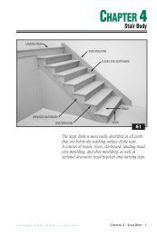
C-3099 MITER JIG<br />
<strong>Coffman</strong> has developed the C-3099 Miter Jig to simplify the<br />
marking and cutting of fittings. The same principles of geometry<br />
used with a pitch block have been combined with a jig that cradles<br />
the fitting for a plumb, square cut. The <strong>Coffman</strong> Miter Jig<br />
provides the fastest, easiest, and most accurate fitting cut available.<br />
1. Position the miter jig on a miter saw with the indexing mark<br />
on the front of the jig aligned with the saw blade.<br />
2. To determine the correct cut on a starting fitting, use your<br />
stair’s rise and run dimensions and the chart on the front of<br />
the jig to determine your stair angle. (See Chart 13-3 for a more<br />
complete listing of rise and run combinations.)<br />
3. All starting fittings are produced with a part called an easing<br />
(See Photo 7-8). The joint formed at the attachment of this<br />
easing will be used as the point of reference when cutting the<br />
fitting. Simply align the joint to the angle on the jig that<br />
matches the angle of your stair and make your cut. An<br />
example rise and run of 7-1/2" x 10" would result in a stair<br />
angle of 36.9°.<br />
4. To cut the lower easing of gooseneck fittings with <strong>Coffman</strong>’s<br />
C-3099 Miter Jig, you must subtract the angle of the stair<br />
from 90°. In our example of a 7-1/2" rise and 10" run, 90° -<br />
36.9° = 53.1°. (The lower number in each box in Chart 13-3 will<br />
automatically give you this angle.) For one-rise goosenecks,<br />
align the joint of the easing to the proper angle and make<br />
your cut. For two-rise goosenecks, use one edge of the loose<br />
easing as the reference point.<br />
C O F F M A N S T A I R P A R T S • S I N C E 1 8 7 4 CHAPTER <strong>12</strong> - <strong>HARDWARE</strong> 1
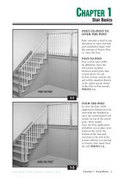
C-3008<br />
SURE-TITE <br />
NEWEL FASTENING SYSTEM<br />
Tools Required - Drill bits: 3/8", 5/8", 1-1/2". 3/4" Box-end wrench<br />
Step 1. Cut post to length. Locate center of post on floor,<br />
and predrill all holes (Fig. A). Important: When drilling post,<br />
drill 1-1/2" hole first. Lag must be installed into<br />
solid blocking.<br />
Step 2. Screw lag into floor and bend top plumb. Two nuts<br />
may be used to create a temporary bolt head (Fig. B).<br />
Step 3. Place post over lag. From 1-1/2" access hole, insert<br />
curved washer and nut. Torque down hard, using a 3/4"<br />
box-end wrench. Plumb post if necessary by cutting bottom<br />
at a slight angle and reapplying. Stress post in all directions<br />
and retighten with torque. Glue hole, tap in plug, and sand<br />
flat (Fig. C).<br />
Contents: 1 lag bolt 10-3/4" long, 1 washer, 1 nut, 3 plugs<br />
FIG. A<br />
3/8"<br />
1"<br />
1-1/2"<br />
5/8"<br />
5/8"<br />
5"<br />
1-1/2"<br />
Drill Bit<br />
5"<br />
2 CHAPTER <strong>12</strong> - <strong>HARDWARE</strong><br />
FIG. B<br />
FIG. C<br />
C O F F M A N S T A I R P A R T S • S I N C E 1 8 7 4
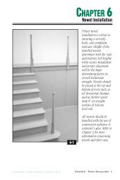
1-1/4"<br />
C-3201<br />
BALUSTER FASTENING KIT/DRIVER<br />
Tools Required - Drill bits: 9/32". Reversible drill<br />
Step 1. Trim baluster to length and predrill a<br />
9/32" x 1-1/4" hole in bottom.<br />
Step 2. Secure driver into a reversible drill. Drive<br />
fasteners 1-1/4" into each baluster.<br />
Step 3. Predrill tread or floor with 9/32" bit and install<br />
baluster by gripping at bottom and twisting into place.<br />
Contents: 1 driver, 4 baluster fasteners 2-1/2" long.<br />
Fasteners also sold separately.<br />
STEP 1. STEP 2. STEP 3.<br />
C-3203<br />
(50 Pack, shown)<br />
C-3203-B<br />
(100 Bulk Pack, not shown)<br />
Driver<br />
C O F F M A N S T A I R P A R T S • S I N C E 1 8 7 4 CHAPTER <strong>12</strong> - <strong>HARDWARE</strong> 3
C-3301<br />
RAIL & POST FASTENER<br />
Tools Required - Socket wrench,<br />
Drill Bits: 1/4", 7/16", 1"<br />
Step 1. Predrill parts as shown.<br />
Step 2. Secure bolt, using<br />
socket wrench.<br />
Step 3. Glue hole, tap in plug,<br />
and sand flat.<br />
Contents: 1 lag bolt 3" long,<br />
1 washer, 2 plugs<br />
C-3302<br />
RAIL-BOLT FASTENER<br />
(carded)<br />
C-3001 RAIL BOLT<br />
(uncarded)<br />
Tools Required - Drill bits: 1/4",<br />
3/8", 1". 1/2” Box-end wrench<br />
Step 1. After trimming rail<br />
to length, drill all holes.<br />
Begin with 1" hole in rail<br />
(Fig. A or B).<br />
Step 2. Using a C-3901<br />
Rail-Bolt Wrench or Vise Grips,<br />
mount bolt into 1/4" hole.<br />
Step 3. Apply glue and join<br />
parts. From 1" access hole,<br />
insert curved washer and nut.<br />
Torque down, using box-end<br />
wrench. Glue hole, tap in<br />
plug, and sand flat (Fig. C).<br />
Contents: 1 fastener 3-1/2"<br />
long, 1 washer, 1 nut,<br />
2 plugs (No plugs in C-3001)<br />
4 CHAPTER <strong>12</strong> - <strong>HARDWARE</strong><br />
STEP 1. STEP 2.<br />
2"<br />
1/4"<br />
1"<br />
FIG. B<br />
1/4" DIA.<br />
3/8" DIA.<br />
7/16"<br />
1" DIA.<br />
1-7/8"<br />
1-1/2"<br />
1-1/2"<br />
15/16"<br />
1"<br />
FIG. A<br />
1-7/8"<br />
1/4"<br />
3/8"<br />
15/16"<br />
1"<br />
1-1/2"<br />
FIG. C<br />
C O F F M A N S T A I R P A R T S • S I N C E 1 8 7 4
C-3505<br />
L-BRACKET POST FASTENER<br />
STEP 1. STEP 2.<br />
The <strong>Coffman</strong> C-3505 L-Bracket Post Fastener consists of four metal<br />
brackets, wood screws, and mitered wood trim pieces.<br />
Step 1. Align the brackets flush with the bottom of the<br />
newel and screw into the face of the newel.<br />
Step 2. Place newel into correct position and install screws<br />
at an angle into the mounting surface.<br />
Step 3. Finish by gluing and nailing the premitered trim<br />
pieces around the brackets.<br />
STEP 3.<br />
C O F F M A N S T A I R P A R T S • S I N C E 1 8 7 4 CHAPTER <strong>12</strong> - <strong>HARDWARE</strong> 5
C-3002<br />
WALL RAIL BRACKET<br />
BRIGHT BRASS<br />
C-3601-A<br />
HEAVY DUTY<br />
WALL RAIL BRACKET<br />
ANTIQUE BRASS<br />
C-3601-B<br />
HEAVY DUTY<br />
WALL RAIL BRACKET<br />
BRIGHT BRASS<br />
See <strong>Chapter</strong> 7,<br />
Pages 27-28 for full<br />
installation instructions.<br />
C-3901<br />
RAIL-BOLT WRENCH<br />
Step 1. Once all the holes<br />
have been drilled, use the<br />
<strong>Coffman</strong> C-3901 Rail-Bolt<br />
Wrench to insert the rail<br />
bolt 2" into the 1/4"<br />
diameter hole in the rail,<br />
post, or fitting (Fig. A).<br />
Step 2. Glue rail and fitting.<br />
With the washer on the rail<br />
bolt, place the nut on the<br />
magnetic pin and apply<br />
rubber band (Fig. B).<br />
Step 3. Press firmly against<br />
the end of the rail bolt and<br />
pull down on the rubber<br />
band to start the nut (Fig. C).<br />
Step 4. The 1/2" boxed-end<br />
of the wrench can then be<br />
used to securely tighten<br />
the nut.<br />
6 CHAPTER <strong>12</strong> - <strong>HARDWARE</strong><br />
WALL TO<br />
CENTER OF BRACKET<br />
2-1/2"<br />
C-3002<br />
C-3601A<br />
WALL TO<br />
CENTER OF BRACKET<br />
2-13/32"<br />
C-3601B<br />
FIG. A<br />
FIG. B<br />
FIG. C<br />
C O F F M A N S T A I R P A R T S • S I N C E 1 8 7 4