EY08 - Jacks Small Engines
EY08 - Jacks Small Engines
EY08 - Jacks Small Engines

Create successful ePaper yourself
Turn your PDF publications into a flip-book with our unique Google optimized e-Paper software.
ROBIN<br />
ROBIN AMERICA, INC.<br />
ROBIN TO WISCONSIN ROBIN<br />
ENGINE MODEL CROSS REFERENCE LIST<br />
<strong>EY08</strong><br />
EY15<br />
EY 15V<br />
EY20<br />
EY2OV<br />
EY23<br />
EY28<br />
EY3 5<br />
EY40 -<br />
EY45V<br />
EY2 1<br />
EY44<br />
EY 18-3<br />
EY25<br />
EY27<br />
EH11<br />
EH12<br />
EH15<br />
EH17<br />
EH21<br />
EH25<br />
EH30<br />
EH30V<br />
EH34<br />
EH34V<br />
EH43V<br />
EC13V<br />
DY23<br />
DY27<br />
DY30<br />
DY3 5<br />
DY4 1<br />
SIDE VALVE<br />
OVERHEAD VALVE<br />
TWO CYCLE<br />
DIESEL<br />
WISCONSIN ROBIN<br />
W 1-080<br />
W1-145<br />
W1-145V<br />
W1-185<br />
W1-185V<br />
W1-230<br />
W 1-280<br />
W 1-340<br />
W 1-390<br />
Wl-45OV<br />
EY21W<br />
EY44W<br />
EY18-3W<br />
EY25W<br />
EY27W<br />
WO1-115<br />
wo1-120<br />
WO1-150<br />
WO1-170<br />
wo1-210<br />
WOl-250<br />
WO 1-300<br />
WO1-300V<br />
WO1-340<br />
WO 1 -340V<br />
WO 1-43 OV<br />
WT1-125V<br />
WRD 1-230<br />
WRD 1-270<br />
-1-300<br />
WRD1-350<br />
WRD1-410<br />
0<br />
0<br />
0
CONTENTS<br />
Section Title Page<br />
1 . SPECIFICATIONS .............................................. 1<br />
2 . PERFORMANCE ............................................... 2<br />
2-1 Maximum Output .......................................... 2<br />
2-2 Continuous Rated Output .................................... 2<br />
2-3 Maximum Torque and Fuel Consumption Ratio at Maximum Output ........ 2<br />
3 . FEATURES .................................................. 3<br />
4 . GENERAL DESCRIPTION of ENGINE CONSTRUCTION ................... 4<br />
4-1<br />
4-2<br />
4-3<br />
4-4<br />
4-5<br />
4-6<br />
4-7<br />
4-8<br />
4-9<br />
4-10<br />
4-1 1<br />
4-12<br />
4-13<br />
4-14<br />
Cylinder. Crankcase ........................................ 4<br />
Main Bearing Cover ......................................... 4<br />
Crankshaft .............................................. 4<br />
Connecting Rod and Piston ................................... 5<br />
Camshaft ............................................... 5<br />
Valve Arrangement ......................................... 5<br />
Cylinder Head ............................................ 6<br />
Governor ............................................... 6<br />
Cooling ................................................. 6<br />
Lubrication .............................................. 6<br />
Ignition ................................................ 7<br />
Carburetor .............................................. 7<br />
Air Cleaner .............................................. 7<br />
Sectional View of Engine ..................................... 8<br />
5 . DISASSEMBLY and REASSEMBLY .................................. 10<br />
5- 1 Preparation and Suggestion .................................... 10<br />
5-2 Special Tools ............................................. 10<br />
5-3 How To Disassemble ........................................ 12<br />
5-4 How To Reassemble ........................................ 16<br />
6 . MAGNETO ................................................... 24<br />
6-1 Magneto ................................................ 24<br />
6-2 Magneto Trouble Shooting .................................... 24<br />
7 . GOVERNOR ADJUSTMENT ....................................... 25<br />
8 . CARBURETOR ................................................ 26<br />
8-1 Operation and Construction ................................... 26<br />
8-2 Disassembly and Reassembly .................................. 27
Section Title Page<br />
9 . BREAK-IN OPERATION Of REASSEMBLED ENGINE ..................... 28<br />
10 . ROBIN SOLID STATE IGNITION ENGINE (U.T.C.I.) ..................... 29<br />
10-1 Features ................................................ 29<br />
10-2 Basic Principle of U.T.C. I ..................................... 29<br />
I1 . ROBIN OIL SENSOR SYSTEM (FLOAT SYSTEM) ....................... 30<br />
11-1 Features ................................................ 30<br />
11 -2 Basic Principle ............................................ 30<br />
11 -3 Checking Procedures ........................................ 32<br />
11 -4 Precautions .............................................. 33<br />
11-5 Wiring ................................................. 33<br />
12 . TROUBLE SHOOTING ........................................... 34<br />
12- 1 Starting Difficulties ......................................... 34<br />
12-2 Engine Misfires ............................................ 35<br />
12-3 <strong>Engines</strong>tops ............................................. 35<br />
12-4 Engine Overheat ........................................... 35<br />
12-5 Engine Knocks ............................................ 36<br />
12-6 Engine Backfires through Carburetor ............................. 36<br />
13 . INSTALLATION ............................................... 37<br />
13-1 Installing ................................................ 37<br />
13-2 Ventilation .............................................. 37<br />
13-3 Exhaust Gas Discharge ....................................... 37<br />
13-4 Power Transmission to Driven Machines ........................... 37<br />
13-5 Wiring ................................................. 38<br />
14 . CHECKS and CORRECTIONS ...................................... 39<br />
15 . TABLE of CORRECTION STANDARDS ............................... 40<br />
16 . MAINTENANCE and STORING ..................................... 45<br />
16-1 Daily Checks and Maintenance ................................. 45<br />
16-2 Every 20 Hours Checks and Maintenance .......................... 45<br />
16-3 Every 50 Hours (IO days) Checks and Maintenance .................... 45<br />
16-4 Every 100 . 200 Hours (Monthly) Checks and Maintenance . ............. 45<br />
16-5 Every 500 . 600 Hours (Semiannual) Checks and Maintenance . ........... 46<br />
16-6 Every 1000 Hours (Yearly) Checks and Maintenance ................... 46<br />
16-7 Preparation for Long Abeyance ................................. 46
1. SPEC1 FICATIOMS<br />
Bore x Stroke (in)<br />
Piston Displacement (cu. in)<br />
Model <strong>EY08</strong>D<br />
<strong>EY08</strong>BN<br />
Air-Cooled, 4-Cycle, Vertical, Single Cylinder Gasoline Engine<br />
51 mm 'x 38 mm (2.01" x 1.50")<br />
77.6 cc (4.74 cu. in)<br />
Compression Ratio 6.5<br />
Continuous Rated Output (HP/rpm)<br />
Max. Output (HP/rpm)<br />
Max. Torque (kg-m/rpm)<br />
1.0/3000<br />
1.4/3600<br />
2.0/4200<br />
0.36/3200<br />
1 .O? 1 500<br />
1.4/1800<br />
2.0/2 1 00<br />
0.72/1600<br />
Direction of Rotation 1 Counterclockwise Facing to P.T.O. Shaft Clockwise Facing to P.T.O. Shaft<br />
Cooling System I Forced Air Cooling<br />
~~<br />
~<br />
Lubrication Splashing Type<br />
Lubricant Automobile Oil Class SC<br />
Carburetor Horizontal Draft, Float Type<br />
Fuel<br />
Fuel Consumption Ratio (gr/Hp-h)<br />
~~<br />
Non-leaded Automobile Gasoline<br />
320 at continuous rated output operation<br />
Fuel Feed I Gravity Type<br />
Fuel Tank Capacity I Approx. 1.5 liter (0.40 U.S. gal.)<br />
Reduction Ratio I - 1 /2<br />
Speed Governor<br />
Spark Plug<br />
Lighting Capacity (V-W)<br />
Starting System<br />
Dry Weight (Ibs.)<br />
Dimensions<br />
System<br />
Length (in)<br />
Width (in)<br />
Height (in)<br />
Flywheel Magneto Type (Solid State Ignition) Ignition<br />
8 kg (17.6 Ibs.)<br />
-1 -<br />
Centrifugal Flyweight Type<br />
NGK-BM4A (S.T.D.)<br />
-<br />
Recoil Starter<br />
252 mrn (9.92")<br />
264 mm (10.39")<br />
326 mm (12.83")<br />
8.5 kg (18.7 Ibs.)
2. PERFORMANCE<br />
2-1 MAXIMUM OUTPUT<br />
The maximum output of an engine is such standard power as developed by the engine, after its initial break-in<br />
period with all the moving parts properly worn in, when operating with a fully open throttle valve, Therefore,<br />
a new engine may not develop the maximum output in the beginning because the moving parts are not in a<br />
properly worn-in condition.<br />
2-2 CONTINUOUS RATED OUTPUT<br />
The continuous rated output of an engine is such power as developed by that engine when running continuously<br />
at an optimum speed, and most favorable from the viewpoint of engine life and fuel consumption ratio,<br />
with the governor in operation. It is suggested, therefore, that when designing a driving system for any mechanism,<br />
with this engine as prime mover, the continuous power requirement of that mechanism be kept below<br />
the continuous rated output specified.<br />
2-3 MAXIMUM TORQUE and FUEL CONSUMPTION RATIO at MAXIMUM OUTPUT<br />
These mean the maximum torque of the output shaft and fuel consumption ratio at the maxiumum output<br />
of an engine.<br />
L<br />
W<br />
0<br />
a<br />
HP<br />
3’<br />
L<br />
0<br />
I<br />
2.5<br />
2.0<br />
1.5<br />
1 .o<br />
0.5<br />
PERFORMANCE CURVE<br />
MODEL <strong>EY08</strong>D<br />
( ) for BN type<br />
0.45 (0.9) kg-rn<br />
2000 3000 4000<br />
(1 000) (1 500)<br />
-<br />
(2000)<br />
Revolution<br />
r.p.m.<br />
-2-<br />
0.40<br />
0.35<br />
0.30
3. FEATURES<br />
1. Compact, lightweight, durable, powerful 4cycle air cooled engine embodying ingenious design techniques<br />
and skilful workmanship.<br />
2. Simple construction, smart appearance, maximum easiness of start owing to automatic decompression<br />
device<br />
3. Pointless Solid State ignition system is newldy adopted for preventing poor igniting.<br />
4. Reliable prime mover for varietyof purposes with smooth speed controlrby a governor under varying load<br />
conditions.<br />
5. Economical because fuel consumption is very low<br />
-3-
4. GENERAL DESCRIPTION of ENGINE CONSTRUCTION<br />
4-1 CYLINDER, CRANKCASE<br />
The cylinder and crankcase are single piece aluminum<br />
die casting. The cylinder liner, made of special<br />
cast iron, is built into the alminum casting. The intake<br />
and exhaust ports are located on one side of<br />
the cylinder, and are also inserted into the casting.<br />
The crankcase is separable on the output shaft side,<br />
where the main bearing cover is attached to it.<br />
(See Fig. 1 .)<br />
4-2 MAIN BEARING COVER<br />
Fig. 1<br />
The main bearing cover made of aluminum die casting is built onto the output shaft side of the crankcase so<br />
that the inside of the engine can readily be checked by simply removing the cover. It is provided with a flange<br />
and boss for directly mounting machines, such as generators and pumps.<br />
Two oil gauges also serving as oil filler caps can be mounted. (See Fig. 2 and Fig. 3.)<br />
Oi I<br />
4-3 CRANKSHAFT<br />
Fig. 2<br />
Ring for Centering<br />
!ID Oil Gauge<br />
The crankshaft is forged of carbon steel, and the<br />
crankpin is induction-hardened. It has a crank gear<br />
pressure-fitted on the output end. (See Fig. 4.)<br />
-4-<br />
Induction Hardening<br />
(Portion of Crankpin)<br />
\<br />
~~<br />
Fig. 3<br />
Crank Gear (Pressure-fit)<br />
Fig. 4
4-4 CONNECTING ROD and PISTON<br />
The connecting rod is made of aluminum die casting,<br />
which itself serves as bearings at both the large and<br />
small ends. The large end cap and the oil scraper are<br />
moulded in a unit for splashing the lubricating oil.<br />
The piston is cast of aluminum alloy, and has grooves<br />
for receiving two compression rings and one oil ring.<br />
(See Fig. 5.)<br />
4-5 CAMSHAFT<br />
In the <strong>EY08</strong>D engine, the camshaft is integrally built<br />
with a cam gear of special cast iron, and has intake<br />
and exhaust cams. Also the camshaft has aluminum<br />
plain bearings attached to both ends. (No ball bearing<br />
is used.) (See Fig. 6.)<br />
In the <strong>EY08</strong>BN engine, the camshaft is forged of carbon<br />
steel and is provided with a force-fit cam gear.<br />
@ It serves also as the driving shaft, being driven at half<br />
the crankshaft speed, and a ball bearing is used at<br />
the P.T.O. shaft side.<br />
4-6 VALVE ARRANGEMENT<br />
The intake valve is located upstream of the cooling<br />
air with the result that the carburetor is intensively<br />
cooled. (See Fig. 7.)<br />
-5-<br />
L<br />
\I<br />
Fig. 5<br />
:Fig. 6<br />
Fig. 7<br />
Top Ring<br />
Second Ring<br />
Oil Ring<br />
Connecting Rod<br />
Oil Scraper<br />
Direction of<br />
Cooling Wind
4-7 CYLINDER HEAD<br />
The cylinder head is an aluminum die casting, and<br />
forms a Ricardo type combustion chamber with<br />
ample area for high combustion efficiency.<br />
(See Fig. 8.)<br />
4-8 GOVERNOR<br />
The governor is a centrifugal flyweight type which<br />
permits constant operation- at the selected speed<br />
against load variations. Govrnor gear is installed on<br />
the bearing cover without fail, and it engages with<br />
the cam gear after reassembling. (See Fig. 9.)<br />
4-9 COOLING<br />
I<br />
Main Be<br />
Fig. 8<br />
Spacer<br />
-<br />
Governor Gear Complete<br />
Q<br />
Fig. 9<br />
!mor Sleeve<br />
The cooling fan serving also as a flywheel cools the cylinder and the cylinder head by forced air cooling. Cyl-<br />
inder baffles and head cover are provided for guiding the cooling air.<br />
4-10 LUBRICATION<br />
The rotating and sliding parts are being lubricated<br />
by scooping and splashing the oil in the crankcase<br />
with the oil scraper. (See Fig. 10.)<br />
-6-<br />
Fig. 10
4-11 IGNITION<br />
The ignition system is a flywheel magneto type with<br />
ignition timing set at 25" before TDC. The magneto<br />
is composed of a flywheel and ignition coil. The flywheel<br />
serving also as a fan is mounted directly on the<br />
crankshaft, and the ignition coil in the crankcase.<br />
(For further details, refer to Section on the Magneto.)<br />
(See Fig. 1 1 .)<br />
4-12 CARBURETOR<br />
A horizontal draft carburetor is employed. It has<br />
been carefully set after thorough tests to assure satisfactory<br />
start up, acceleration, fuel consumption, output<br />
performance, etc.<br />
For construction and order details, refer to the Section<br />
on Carburetor Construction, Disassembly and<br />
@ Reassembly. (See Fig. 12.)<br />
4-13 AIR CLEANER<br />
The air cleaner of the standard ty :ngine is an 0 b-<br />
long type using a sponge element. (A cyclone type<br />
semi-wet double element air cleaner is optionally<br />
available.) (See Fig. 13.)<br />
-7-<br />
I Ignition Coil<br />
Air Cieaner for<br />
Standard Type<br />
Fig. 1 1<br />
Fig. 12<br />
Fig. 13<br />
Cyclone Type<br />
(Option)
4-14 SECTIONAL VIEW of ENGINE<br />
MODEL <strong>EY08</strong>D<br />
-8-
Stop Button<br />
Connecting Rod<br />
Crankcase<br />
MODEL <strong>EY08</strong>D<br />
-9-<br />
Air Cleaner<br />
Carburetor<br />
Intake and<br />
Exhaust Valve<br />
Tappet<br />
Camshaft<br />
Governor Shaft
5. DISASSEMBLY and REASSEMBLY<br />
5-1 PREPARATIONS and SUGGESTIONS<br />
1) When disassembling the engine, remember well the locations of individual parts so that they can be reas-<br />
sembed correctly. If you are uncertain of identifying some parts, it is suggested that tags be attached to<br />
them.<br />
2) Have boxes ready to keep disassembed parts by group.<br />
3) To prevent missing and misplacing, temporarily assemble each group of disassembed parts.<br />
4) Carefully handle disassembed parts, and clean them with washing oil.<br />
5) Use the correct tools in the correct way.<br />
5-2 SPECIAL TOOLS<br />
For your reference, the following shows special tools of Robin Engine for Disassembly, Measuring and Inspec-<br />
tion Instruments.<br />
Part No.<br />
2099500407<br />
2309500107<br />
2079500307<br />
2309500207<br />
2059500107<br />
Tool<br />
Flywheel Puller<br />
(with bolt)<br />
Valve Spring<br />
Retainer<br />
Valve Guide<br />
Puller<br />
Use<br />
For pulling off<br />
Flywheel<br />
For mounting and<br />
dismounting Valve<br />
Spring Retainer<br />
and Retainer Lock<br />
For pulling off<br />
Valve guide<br />
Applicalbe<br />
Model<br />
<strong>EY08</strong><br />
EY10, 13, 14<br />
EY 15,18, 20<br />
EY23, 25, 27,<br />
EY33<br />
EY35,40,44<br />
EC05.07, 10<br />
EC17,25.37<br />
<strong>EY08</strong><br />
EY10,13, 14<br />
EY 15, 18,20<br />
EY23<br />
EY25.27, 33<br />
EY35,40,44<br />
<strong>EY08</strong><br />
EY10<br />
EY13, 14<br />
-10-<br />
Shape
Part No.<br />
2069500107<br />
2279500107<br />
207 95001 07<br />
“20248<br />
Tool<br />
Valve Guide<br />
Puller<br />
Timing Tester<br />
Use<br />
For pulling off<br />
Valve guide<br />
For adjusting<br />
timing<br />
Applicalbe<br />
Model<br />
EY18.23<br />
EY 15,ZO<br />
EY25, 27<br />
EY10, 13, 14<br />
EY 15, 18,20<br />
EY25,27,33<br />
EY35,40,44<br />
EC03,04,05<br />
EC07,10, 17<br />
EC25,37<br />
- 11 -<br />
Shape
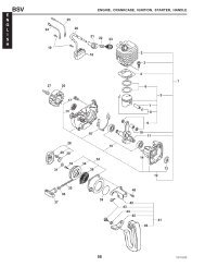
5-3 HOW TO DISASSEMBLE<br />
Order<br />
5<br />
I tern<br />
Fuel tank<br />
Recoil starter<br />
Tank bracket<br />
Head cover<br />
Fan cover<br />
Muffler cover<br />
Muffler<br />
Air cleaner<br />
L<br />
*Length of the bolt indicates the length from the bolt head bottom surface to the threaded end.<br />
Procedures<br />
(1) Close the fuel cock.<br />
(2) Disconnect the fuel pipe between the fuel<br />
strainer and carburetor at the carburetor<br />
side.<br />
(3) Remove the fuel tank from the tank bracket.<br />
M6 x 14 mm bolt : 3 pcs.<br />
(1) Remove the recoil starter.<br />
M6 x 8 mm bolt : 3 pcs.<br />
(1) Remove the tank bracket, the head cover,<br />
and the fan cover from the crankcase and<br />
the cylinder head.<br />
M6 x 10 rnm bolt : 2 pcs.<br />
M6 x 12 bolt : 1 pce.<br />
M6 nut : 2 pcs.<br />
(1) Remove the muffler cover 1 from the<br />
muffler.<br />
M6 x 8 mm bolt : 2 pcs.<br />
(2) Remove the muffler from the cylinder<br />
portion of the crankcase.<br />
M6 x 28 mrn bolt : 1 pce.<br />
M6 x 50 mm bolt : 1 pce.<br />
(1) Remove the air cleaner cover and the<br />
element.<br />
(2) Remove the air cleaner case from the<br />
carburetor.<br />
M6 nut : 2 pcs.<br />
(3) Disconnect the breather pipe.<br />
Governor Lever<br />
Governor Spring<br />
Lock Bolt<br />
Governor Shaft<br />
Sems bolt<br />
Remarks<br />
Fastened together<br />
Remove the primary<br />
wire of the stop but-<br />
ton.<br />
Air cleaner is fasten-<br />
ed together with the<br />
carburetor.<br />
{--) ,Governor Rod Spring<br />
Fig. 14<br />
- 12 -<br />
Governor Rod<br />
Lever<br />
' High Speed Set Screw<br />
Tool<br />
10 mm box spanner<br />
IO mm box spanner<br />
10 m box spanner<br />
Ir 10 mm spanner<br />
10 mm box spanner<br />
x 10 mm spanner<br />
10 mm box spanner
Order Itern Procedures I Remarks I Too I<br />
6 Governor lever<br />
and the relative<br />
parts<br />
Carburetor<br />
Starting pulley<br />
Flywheel<br />
(1) Remove the governor Iever from the governor<br />
shaft.<br />
M6 x 25 mm bolt : 1 pce.<br />
(2) Remove the governor rod and rod spring<br />
from the carburetor.<br />
(3) Remove the carburetor from the<br />
cylinder portion of the crankcase.<br />
Just loosen the bolt,<br />
unnecessary to take<br />
out the bolt.<br />
(1) Remove the starting pulley from the fly- Be careful not to<br />
wheel. damage the blades of<br />
M12 nut : 1 pce. the flywheel with a<br />
Fit a box or socket wrench over the fly- driver and a like.<br />
wheel nut, and strike it hard with a ham- Strlke counterclockmer<br />
to remove the nut and spring washer. wise with a hammer.<br />
(See Fig. 15)<br />
(1) Remove the flywheel from the crankshaft. Fit the flywheel<br />
puller as shown in<br />
Fig. 16, turn the<br />
center bolt clock-<br />
wise and pull out<br />
the flywheel.<br />
Fig. 15<br />
~ ~~~~~~~~~~~ ~ ~~<br />
Order I tern Procedures<br />
9 Ignition coil (1) Remove the plug terminal from the spark<br />
plug and remove the ignition coil from the<br />
crankcase.<br />
M6 x 25 mm bolt : 2 pcs.<br />
10 (1) Remove the spark plug from the cylinder<br />
Spark plug<br />
he ad<br />
- 13 -<br />
Fig. 16<br />
Remarks<br />
10 mm box spanner<br />
or 10 mm spanner<br />
17 mm box spanner<br />
or socket wrench<br />
Sems bolt 710 mm box spanner<br />
I19 mm box spanner
Order I Item<br />
\ (-) Driver<br />
11 Cylinder head<br />
I<br />
l2 I<br />
Intake and<br />
exhaust valve<br />
13 I Main bearing<br />
cover<br />
\<br />
Procedures<br />
(1) Remove the M6 bolts and remove the cylinder<br />
head from the crankcase<br />
M6 x 32 mm bolt : 5 pcs.<br />
M6 x 40 mm bolt : 2 pcs.<br />
(2) Remove the cylinder head gasket from the<br />
crankcase.<br />
(1) Remove the inner and outer tappet covers<br />
from the crankcase.<br />
M6 x 12 mm bolt : 2 pcs.<br />
(2) Pull out the intake and exhaust valve.<br />
(3) Remove the valve spring and the valve<br />
spring retainer.<br />
(1) From the crankcase remove the bolt fastening<br />
the main bearing cover.<br />
M6 x 25 mm bolt : 6 pcs.<br />
(2) Remove the cover, lightly tapping the cover<br />
evenly with a plastic hammer.<br />
Fig. 17<br />
- 14 -<br />
Remarks<br />
M6 x 40 mm bolt is<br />
special bolt.<br />
Put the notch on the<br />
outer circumference<br />
of the spring retainer<br />
on this side.<br />
Hook the medium<br />
size (-) driver at the<br />
dent (lower side) of<br />
the spring retainer<br />
and pull out the<br />
valves, while pulling<br />
the spring retainer<br />
toward you.<br />
(See Fig. 17.)<br />
Sems bolt<br />
I Plastic Hammer<br />
Be careful not to<br />
damage the oil seal.<br />
(See Fig. 18.)<br />
Fig. 18<br />
Tool<br />
10 mm box spanner<br />
The front is this sidf<br />
(-) driver<br />
10 mm box spanner<br />
Main/Bearing Cover
15 Tappet<br />
Order<br />
16<br />
17<br />
18<br />
Procedures I Remarks I Too I<br />
(1) Remove the camshaft from the crankcase. To prevent the tappets<br />
from falling or<br />
damaging, place the<br />
crankcase on the<br />
side. (See Fig. 19 .)<br />
I (1) Remove the tappets from the crankcase. Before removing put<br />
a mark of intake or<br />
exhaust on each<br />
tappet.<br />
~~~ ~~~~ ~~~ ~~<br />
I tern<br />
Connecting rod<br />
and piston<br />
Piston and<br />
piston pin<br />
Crankshaft<br />
Procedures<br />
Camshaft<br />
(1) Scrape off carbon and other foreign deposits<br />
from the upper parts of the cylinder and<br />
piston, and then straighten out the bent<br />
tabs of the lock washers on the connecting<br />
rod, and remove two pieces of the bolt.<br />
(2) Remove the lock washer and the connecting<br />
rod cap from the crankshaft.<br />
(3) Turn the crankshaft until the piston is raised<br />
up to the hghest position, push the connecting<br />
rod up, and remove the piston out of the<br />
top of the cylinder.<br />
(1) Remove the two clips, pull out the piston<br />
pin, and take the piston off from the small<br />
end of the connecting rod.<br />
(2) Spread the open ends of the piston rings<br />
and remove them from the piston.<br />
(1) Remove the woodruff key (for the mag-<br />
neto).<br />
(2) Lightly hammer the magneto end of the<br />
crankshaft, and pull it out of the crank-<br />
case.<br />
- 15 -<br />
Remarks I Tool<br />
Pay attention to the<br />
direction of the con-<br />
necting rod cap.<br />
Be careful not to<br />
damage the inside of<br />
the small end of the<br />
connecting rod.<br />
Be careful not to<br />
break the rings by<br />
spreading too much.<br />
Be careful not to<br />
damage the oil seal.<br />
8 mm box spanner<br />
or 8 mm spanner
5-4 HOW TO REASSEMBLE<br />
.Precaution in reassembling<br />
Every and each part should be cleaned thoroughly. Especially, pay utmost care and attention to the cleanliness<br />
of the piston, cylinder, crankshaft, connecting rod and bearings.<br />
Scrape completely off carbons from the cylinder head and the upper part of the piston; especially the<br />
carbon adhered in the groove of the piston ring should be carefully and completely taken out.<br />
Carefully check the lip portion of every oil seal. If faulty one is found, replace it without any hesitation.<br />
Apply enough oil to the lip portion of the oil seal when reassembling.<br />
Replace all the gaskets with new ones.<br />
Replace the key, pin, bolt, nuts, etc. with new one, if necessary.<br />
Whenever tightening torque is specified, conform to the specified figures.<br />
Apply oil to the revolutionary parts and friction surfaces, when reassembling.<br />
Check and adjust the clearances of various portions and then reassemble.<br />
When some main portions are assembled in the course of reassembling, turn or move the gadgets by hand<br />
and pay attention to the frictional noise and resistance.<br />
*Sequence and precautions in reassembling<br />
5-4-1 GOVERNOR SHAFT<br />
1) Insert the governor shaft into the crankcase.<br />
2) Place the clips on the governor shaft.<br />
5-4-2 CRANKSHAFT<br />
1) Inser the crankshaft into the crankcase as shown<br />
in Fig. 20.<br />
. Note: Be careful not to damage the oil seal lip.<br />
2) Put woodruff key (for magneto) in place.<br />
-16-<br />
Fig. 20<br />
Shaft
3) Dimensions of Crankshaft Pin<br />
D (Crankshaft Pin Dia.) 20 dia. -0.037<br />
- 0.050<br />
W (Crankshaft Pin Width)<br />
PISTON TO CYLINDER AT PISTON SKIRT<br />
THRUST FACE<br />
tx"--+<br />
I<br />
TOP, SECOND<br />
PISTON RING GAP<br />
PISTON RING CLEARANCE<br />
IN GROOVES i<br />
CONNECTING ROD TO CRANK PIN<br />
CONNECTING ROD TO PISTON PIN<br />
PISTON PIN TO PISTON<br />
0.008L - 0.047L<br />
0.2 L - 0.4L<br />
0.05L - 0.25L (Cutter Ring)<br />
TOP RING<br />
0.09OL -0.135L<br />
SECOND RING<br />
0.060L - 0.105L<br />
OIL RING<br />
0.01OL - 0.065L (Cutter Ring)<br />
DIA<br />
0.037L - 0.063L<br />
0.1 L - 0.7L<br />
Fig. 21<br />
- 17-<br />
0.010L - 0.029L<br />
0.009T - 0.01OL<br />
L: LOOSE<br />
T: TIGHT
5-4-3 PISTON and PISTON RING<br />
1) If no ring expander is available, install the rings by placing the open ring ends over the first land of the<br />
piston and spreading the rings only far enough to slip them over the correct ring grooves.<br />
Note: Pay attention not to break the rings by twisting. Install the oil ring first followed by the second<br />
ring and then top ring. Meantime, the surfaces of the second ring and the top ring with carved<br />
carved marks are to be faced up.<br />
Note: When replacing the piston rings with new ones, install the rings for replacement as shown in Fig.<br />
22.<br />
I @ STD I Replacement Parts I<br />
Top Ring Taper Taper<br />
I I<br />
Second Ring Taper Undercut Q l<br />
2) Reassemble the piston and the connecting rod by<br />
means of the piston pin.<br />
Note: Apply enough oil to the small top end of<br />
the connecting rod.<br />
Be sure to place the clips on both ends of<br />
the piston pin.<br />
3) When installing the connecting rod into place,<br />
hold piston rings with the ring guide as shown in<br />
Fig. 24 (if no ring guide is available, keep pressing<br />
the piston rings with finger tips and gently<br />
strike the top of the piston with a wooden piece<br />
or the like to push it in), and check that the symbol<br />
@ or mark MA on the connecting rod is i<br />
the direction of the flywheel magneto.<br />
Note: Apply enough oil to the piston rings, connecting<br />
rod plain bearings and cylinder<br />
wall before reassembling.<br />
Note: The open ends of the piston rings must be<br />
90" apart from one another on the piston<br />
periphery.<br />
Note: The clearance between the piston and cylinder<br />
must be measured at the piston skirt<br />
thrust surface.<br />
a<br />
Oil Ring Cutter Ring<br />
Assembly type<br />
Fig. 22<br />
- 18 -<br />
Fig. 23<br />
Fig, 24<br />
Crank Case<br />
(Magneto Side)<br />
n
5-4-4 CONNECTING ROD<br />
# 1) Turn the crankshaft to the bottom dead center,<br />
lightly hammer the piston head until the connecting<br />
rod contacts the crankpin, and assemble.<br />
2) When reassembling the connecting rod cap, set it<br />
so that the oil scraper is in the right.bottom.<br />
(See Fig. 25.)<br />
Note: Use new lock washers, and bend the tabs<br />
securely,<br />
Note: After reassembly, confirm that the connecting<br />
rod moves lightly.<br />
Note: Connecting rod cap tightening torque:<br />
60 - 80 kg-cm<br />
Note: For the piston, piston ring and- rod clearance,<br />
see Fig. 2 1.<br />
5-4-5 TAPPET and CAMSHAFT<br />
Insert the tappets back into their holes first, and<br />
then mount the camshaft.<br />
Note: Align the timing mark at the root of a tooth<br />
of the cam gear with the one on the crank<br />
gear. If the valve timing is wrong, the engine<br />
cannot operate properly or at all. (See Fig.<br />
26. )<br />
Note: If the intake tappet and exhaust tappet were<br />
assembled contrarily each other, the tappet<br />
clearance cannot be kept correctly.<br />
- 19 -<br />
Fig. 25<br />
Fig. 26
5-4-6 MAIN BEARING COVER<br />
Install the main bearing cover to the.crankcase.<br />
Note: As the'governor gear is mounted on the main<br />
bearing cover side, install the main bearing<br />
cover while checking that it meshes with the<br />
teeth of the cam gear. (See Fig. 27.) Meantime,<br />
if the oil seal need be replaced, pressure-fit a<br />
new oil seal before installing the main bearing<br />
cover.<br />
Note: When installing main bearing cover, apply oil<br />
to the bearing and oil seal lip. Fit the oil seal<br />
guide over the crankshaft or camshaft to pro-<br />
tect the oil seal lip from damage. Then place<br />
the main bearing cover on.<br />
Check the crankshaft if its side clearance is<br />
0 - 0.2 mm; and if not, adjust it with the ad-<br />
justing shim. (See Fig. 28,)<br />
Note: In the BN type, adjust the side clearance of<br />
the cam shaft with the adjust shim so that it is<br />
from 0 to 0.2 mm.<br />
Note: Main bearing cover tightening torque:<br />
80 - 100 kg-cm<br />
Note: Fig. 29 shows one of the methods measuring<br />
the crankshaft side clearance between the<br />
machined face of the crankcase and adjusting<br />
collar. As a paper packing is used on the ma-<br />
chined face of the crankcase, adjust the clear-<br />
ance by taking this thickness of0.22 mm into<br />
account. (See Fig. 29.)<br />
- 20 -<br />
-1<br />
Pay attention to the engagement of<br />
the governor ear and cam gear.<br />
I t<br />
Fig. 27<br />
Fig. 28<br />
1 (*-* Dial Indicator<br />
Ground Surface of<br />
(The surface of the crankcase is<br />
to be put together with the sur-<br />
face of the main bearing cover.)<br />
Fig. 29
5 -4-7 INTAKE and EXHAUST VALVES<br />
Remove carbon and gum deposite from the valves, valve seats, intake and exhaust ports and valve guides,<br />
Note: If the valve face is dinted or warped, replace the valves with new ones.<br />
Note: If there is an excessive clearance between the valve guide and valve stem, replace the valve guide with a<br />
spare. For replacing, pull out the valve guide, using the valve guide pulling base and bolts as shown in<br />
Fig. 30, and pressure-fit a new valve guide into place.<br />
Valve Face<br />
% Spring Retainer<br />
Fig. 30<br />
VALVE and VALVE GUIDE CLEARANCE<br />
I A-VALVE FACE I ANGLE<br />
4 5" I<br />
I B- SEAT ANGLE I 45" I<br />
C-GUIDE INSIDE DIA. 5.5 dia. +0.018<br />
0<br />
I CLEARANCE MAXIMUM ALLOWABLE<br />
BETWEEN C and D<br />
INTAKE<br />
EXHAUST<br />
Fig. 31<br />
- 27 -<br />
0.020L - 0.050L<br />
0.056L - 0.092 L<br />
L: LOOSE
5-4-8 TAPPET ADJUSTMENT<br />
Lower the tappet all the way down, push the valve, and insert a thickness gauge between the valve and tap-<br />
pet stem to measure the clearance. (See Fig. 32.)<br />
Note: The correct tappet clearance for both intake and exhaust valves is 0.1 mm k0.02 mm as measured<br />
when the engine is cold.<br />
Fig. 32<br />
Thickness Gauge<br />
I Valve<br />
Valve Spring<br />
Valve Spring Retainer<br />
fig. 33<br />
- Note: If the clearance is smaller than specified, slightly grind the top of the valve stem, and measure it again.<br />
On the contrary, if the clearance is too large, replace the valve with new one, and polish its contact<br />
surface with a compound to obtain a good fit. Then adjust the clearance.<br />
Note: After the tappet clearance adjustment, install the valve springs and the valve spring retainers, and turn<br />
the crankshaft, and measure the tappet clearance once again if it is correct.<br />
Note: INSTAL LA TION of SPRING RETAINERS<br />
Place the notch on the outer circumference of<br />
the retainer toward this side and insert the re-<br />
tainer, like pushing in, using a special tool. lf<br />
a driver is used, insertion may be easier.<br />
Front should be this side.<br />
5-4-9 CYLINDER HEAD<br />
\-I Driver<br />
‘ \<br />
Fig. 34<br />
Valve Spl k g<br />
l Retainer<br />
Remove carbon from the cylinder head, particularly its combustion chamber, and make clean the cooling<br />
fins. Also check the head for distortion.<br />
Note: Replace the cylinder head gasket with a new one.<br />
Note: Cylinder head tightening torque: 90 - 110 kg-cm<br />
- 22 -<br />
n<br />
/”-.
-<br />
5-4-10 SPARK PLUG<br />
Tightening torque of the spark plug: 230 - 250 kg-cm.<br />
Note: If the spark plug is new, tighten the spark plug at 120 - 150 kg-cm torque.<br />
5-4- 11 IGNITION COIL, FLYWHEEL and STARTER PULLEY<br />
1) Temporarily fasten the ignition coil to the crankcase, and install the flywheel to the crankshaft. Starting<br />
pulley is fastened together with the flywheel.<br />
Note: Before installing, wipe out oil from the crankshaft and the tapered portion of the flywheel.<br />
Note: Before installing the starting pulley, check if the woodruff key is correctly inserted.<br />
Note: Flywheel tightening torque: 450 - 500 kg-cm.<br />
2) After measuring the air gap between the ignition<br />
coil and flywheel, retighten the ignition coil.<br />
(See Fig. 35.)<br />
Air gap: 0.3 - 0.5 mm<br />
5 -4- 12 CARBURETOR<br />
I<br />
Fig. 35<br />
To the cylinder portion of the crankcase install in the order of the gasket, insulator, gasket and carburetor,<br />
and then mount the air cleaner case and fasten with two pieces of M6 nut.<br />
5 -4- 13 GOVERNOR LEVER<br />
When reassemblying, refer to the 7. GOVERNOR ADJUSTMENT.<br />
5-4-14 MUFFLER and MUFFLER COVER<br />
Install the muffler cover 2 to the muffler and fasten the muffler to the crankcase and then install the muffler<br />
cover 1.<br />
Note: Muffler tightening torque: 100 - 720 kg-cm<br />
Note: Clamp the muffler and tighten the bolts after engine the has been fully cooled.<br />
5-4-15 HEAD COVER, FUEL TANK, FUEL TANK BRACKET and FAN COVER<br />
Install in the order of the head cover, fan cover, fuel tank bracket and fuel tank.<br />
Note: Install the grommet of the ignition coil to the head cover before installing the fan cover.<br />
5-4- 16 RECOIL STARTER<br />
- With 3 pieces of M6 x 8 mm bolt fasten the recoild starter.<br />
Note: It is feared that the bolt longer than 8 mm may damage the blade.<br />
- 23 -
6. MAGNETO<br />
6-1 MAGNETO<br />
The spark for ignition is furnished by the magneto assembly. The magneto consists of the flywheel and the<br />
ignition coil of which flywheel is mounted on crankshaft and ignition coil is mounted in crankcase directly.<br />
6-2 MAGNETO TROUBLE SHOOTING<br />
When the engine does not start or starts with difficulty, or when its operation is unstable, the following tests<br />
will clarify if they are caused by a defect in the magneto.<br />
1) Check ignition cable for possible corrosion, broken, worm insulator or lose connection.<br />
2) Check the sparking as described later in this section.<br />
3) If no spark takes place, replace ignition coil.<br />
*SPARK TESTING<br />
Remove the spark plug from the cylinder head and place it on the cylinder head, with the ignition cable<br />
connected to it.<br />
Crank the engine several times by recoil starter and observe the spark in the spark gap of spark plug. If<br />
the spark is strong, the ignition system can be eliminated as the source of trouble. (Remove the primary<br />
wire from the connector.)<br />
If the spark is weak or there is no spark at all, repeat the checks.<br />
The correct electrode gap is 0.6 - 0.7 mm. (Refer to section “14. CHECKS and CORRECTIONS.”)<br />
Flywheel<br />
I<br />
Fig. 36<br />
- 24 -<br />
/-<br />
/“
7. GOVERNOR ADJUSTMENT<br />
Model <strong>EY08</strong> emploies a centrifugal flyweight type governor. The governor is mounted on the govenor gear<br />
- and the throttle valve of the carburetor is automatically regulated by a lever which is connected to the gover-<br />
nor in order to maintain constant engine speed against load variations.<br />
The adjustment procedure of the governor is as follows (See Figs. 37 - 39.):<br />
1) Connect the carburetor throttle lever to the governor lever with the governor rod and the rod spring and<br />
mount the governor lever onto the governor shaft.<br />
2) Install the speed control lever to the crankcase.<br />
3) Connect the governor lever to the control lever with the governor spring.<br />
Governor Lever<br />
Governor Spring<br />
Governor Shaft<br />
b 4) Turn the control lever towards high speed, and<br />
confirm that the carburetor throttle valve is fully<br />
opened. Control lever can stay wherever it is<br />
required.<br />
*Position to hang the governor spring<br />
The standard position is 2-A. But, in case of a<br />
50Hz generator, the governor should be hung at<br />
3-B .<br />
5) With a screwdriver in the groove of the governor<br />
shaft, turn it “clockwise” fully until the governor<br />
shaft no longer moves, and then look the<br />
governor lever to the governor shaft with the<br />
governor lever tightening bolt. (See Fig. 39.)<br />
Fig. 37<br />
- 25 -<br />
Governor Rod<br />
An example of the governor spring being hooked.<br />
Fig. 38<br />
Governor Lever<br />
Fig. 39
8. CARBURETOR<br />
8-1 OPERATION and CONSTRUCTION (See Fig. 40.)<br />
8- 1 - 1 FLOAT SYSTEM<br />
The float chamber is located just below the carburetor body and, with a float and a needle valve, maintains<br />
a constant fuel level during engine operation.<br />
The fuel flows from the fuel tank into the float chamber through the needle valve. When the fuel rises to a<br />
specific level, the float rises; and when its buoyancy and fuel pressure are balanced, the needle valve close to<br />
the shut off the fuel, thereby keeping the fuel at the reference level.<br />
Main Air Jet<br />
Float -<br />
Pilot Jet, ,,"--Pilot Air Jet<br />
fig. 40<br />
- 26 -<br />
r Pilot Jet<br />
/-<br />
Needle Valve<br />
/-
8-1 -2 PILOT SYSTEM<br />
The pilot system feeds the fuel to the engine during idling and low-speed operation.<br />
The fuel is fed through the main jet to the pilot jet, where it is metered, and mixed with the air metered by<br />
the pilot air jet.<br />
The fuel-air mixture is fed .to the engine through the pilot outlet and the by-pass.<br />
During engine idling, the fuel is mainly fed from the pilot outlet.<br />
8- 1-3 MAIN SYSTEM<br />
The main system feeds the fuel to the engine during medium- and high-speed operation.<br />
The fuel is metered by the main jet and fed to the main nozzle. The air metered by the main air jet is mixed<br />
with the fuel through the bleed holes in the main nozzle, and the mixture is atomized out of the main bore.<br />
It is mixed again with the air taken through the air cleaner into an optimum fuel-air mixture, which is<br />
supplied to the engine.<br />
8- 1 -4 CHOKE<br />
The choke is used for easy start in the cold season. When the recoil starter is pulled with a closed choke, the<br />
negative pressure applied to the main nozzle increases and draws much fuel accordingly; thus easily start up<br />
the engine.<br />
8-2 DISASSEMBLY and REASSEMBLY<br />
Apart from mechanical failures, most of carburetor troubles are caused by an incorrect mixing ratio, which<br />
may arise mainly due to a clogged up air or fuel passage in jets, or fuel level variations. In order to assure<br />
proper flow of air and fuel, the carburetor must be kept clean at all times. The carburetor disassembly and<br />
reassembly procedures are as follows: (See Fig. 41 .)<br />
18<br />
8-2- 1 THROTTLE SYSTEM<br />
1) Remove the Philips screw (1 8) and throttle valve<br />
(19), and pull out the throttle shaft (20).<br />
2) The spirng (21) can be taken out by removing<br />
the throttle stop screw (22).<br />
*Exercise care not to damage throttle valve ends.<br />
8-2-2 CHOKE SYSTEM<br />
1) Remove the Philips screw (14) and choke valve<br />
(1 S), and pull out the choke shaft (1 6).<br />
2) When reassembling the choke shaft, make sure<br />
that the cutout in the choke valve faces the main<br />
air jet.<br />
8-2-3 PILOT SYSTEM<br />
Remove the pilot jet (23) using correct tool to<br />
avoid damage to it.<br />
Reassembly<br />
Tighten the pilot jet securely. Otherwise, the fuel<br />
may leak, causing engine malfunction.<br />
- 27 -<br />
7<br />
12 A<br />
Fig. 4 1<br />
17
8-2-4 MAIN SYSTEM<br />
1) Remove the bolt (12) and take out float chamber body (10).<br />
2) Remove the main jet (1 3) from the body (6).<br />
3) Reassembly<br />
a) Fasten the main jet securely to the body. Otherwise the fuel may become too rich and cause engine<br />
malfunction.<br />
b) The bolt tightening torque is 70 kg-cm.<br />
8-2-5 FLOAT SYSTEM<br />
Pull out the float pin (9) and remove the float (8) and needle valve (1 7). If the needle valve need be re-<br />
placed, replace it with rubber needle.<br />
Caution: When cleaning the jets, use neither a drill nor a wire (because of possible damage of the orifice<br />
which will adversely affect fuel flow). Be sure to use compressed air to blow them clean.<br />
When removing the needle valve and floats, gently tap the reverse side using the rod more slender than<br />
the float pin and remove because the float pin is calked to the carburetor body.<br />
BREAK-IN OPERATION of REASSEMBLED ENGINE<br />
An overhauled engine must be operated at low speed break-in the parts. A thorough break-in is indispensable<br />
particularly when the cylinder, piston, piston rings or valves are replaced with new ones.<br />
The recommended break-in schedule is shown below.<br />
I<br />
LOAD<br />
NO LOAD 3,000 rpm<br />
NO LOAD<br />
0.7 PS<br />
SPEED<br />
(Crankshafr Rev.) TIME I<br />
2,500 rpm<br />
10 minutes<br />
3,600 rpm<br />
3,600 rpm<br />
10 minutes<br />
10 minutes<br />
30 minutes<br />
1.4 PS 3,600 rpm<br />
60 minutes<br />
- 28 -<br />
/-
10. ROBIN SOLID STATE IGNITION ENGINE' (U.T.C.I.)<br />
b 10-1 FEATURES<br />
<strong>EY08</strong> emploies a pointless ignition system, called Solid State Ignition, which is the circuit breaker type ignition<br />
device, utilizing the power transistor as an element for controling electric current. This ignition system is<br />
called U.T.C.I. (Universal Type Transistor Controlled Ignition), and it is based on an external coil system<br />
in which an ignition coil is installed outside the flywheel and the unit is mounted on an iron core of the coil.<br />
Being different from the breaker point type ignition system, this brand-new system is completely free from<br />
such troubles as starting-up failure owing to dirty, burnt or oxidized point surface, lowering of ignition efficiency<br />
being caused by moisture, rough surface<br />
mechanical parts.<br />
to breaker point and incorrect timing resultant from worn<br />
10-2 BASIC PRINCIPLE OF U.T.C.!. (See Fig. 42.)<br />
Electricity is generated in the primary ignition coil by rotation of the flywheel, and the current a flows,<br />
by which the condenser is charged.<br />
When the flywheel goes round further, direction of the current changes, and the current b flows, causing<br />
the current c and the current d flow to the power transistor and the transistor for<br />
condenser8is charged by the current d contrarily to the case 1).<br />
signals for each. The<br />
When the flywheel goes round further more, the current generated<br />
and then begins decreasing.<br />
in the primary coil gets to its peak,<br />
Then, voltage between C (Collector) and E (Emitter) of the transistor for signals becomes zero, and the<br />
transistor is turned OFF, while the current<br />
thyrister (SCR), thus turning the SCR ON.<br />
d changes to the current e and goes into the gate of the<br />
When the SCR is switched ON and the current b flows into the SCR (Current f), the current c flowing<br />
the power transistor is interrupted abraptly, generating high voltage by the current change in the secondary<br />
coil, thus giving sparks to the spark plug.<br />
Fig. 42<br />
- 29 -<br />
ignition Coil
1.1. ROBIN OIL SENSOR SYSTEM (FLOAT SYSTEM)<br />
In the EYOS, an oil sensor is available as a maker option.<br />
11 - 1 FEATURES<br />
1) The engine oil sensor detects the quantity of engine oil and automatically stops the engine, if it falls<br />
below the specified level, to prevent the engine from burning due to oil maintenance failure or for other<br />
reasons.<br />
If the oil shortage warning lamp is connected to the connecting terminal for it. the warning lamp is lit<br />
when the engine stops.<br />
2) If the engine oilis short when the engine is started, the engine can not be started, even if the recoil starter<br />
is pulled. If the warning lamp is connected, the lamp is lit to indicate oil shortage.<br />
3) As the power generated by the igniter is used, any special power supply unit is not necessary.<br />
4) On-tatch stop is possible also by using the stop button, which is generally incorporated in the unit, based<br />
on a push button system. (Self-maintaining and automatic restoration circuits are incorporated in the<br />
unit.)<br />
5) This system features the malfunction preventing structure depending on outer magnetic field.<br />
11 -2 BASIC PRINCIPLE<br />
This oil sensor system consists<br />
sensor.<br />
of a flywheeI magneto, an igniter, an oil level controller, and an oil level<br />
As shown in Fig. 43, when the oil level is above the specified one, the lead switch contact is OFF, and the<br />
engine can run normally (sensor OFF condition). If the oil becomes short and position of the float in the /"<br />
sensor case goes down to the specified level shown in Fig. 44, the lead switch contact is turned ON by the<br />
magnetic field of the permanent magnet incorporated in the float (sensor ON condition).<br />
When the oil level sensor is turned ON, the current il generated by the counter-electromotive voltage VI in<br />
the primary ignition coil flows from the primary wire of the igniter via the delaying circuit of the oil level<br />
controller, both of which are shown in the block diagram. When the current iI generated by the counter<br />
electromotive voltage VI goes up to a certain level, the current il is loaded to the SCR gate from the delaying<br />
circuit via the self-maintaining circuit if V, is loaded.<br />
Then, the SCR is turned ON, thus starting operation of the warning lamp driving circuit, lgighting the warning<br />
lamp to indicate the oil shortage condition, and completely short-circuiting the regular electromotive<br />
voltage V, in the primary coil of the igniter for the igniter not to generate sparks. This condition is continued<br />
until the engine is stopped by the self-maintaining circuit.<br />
In normal stopping operation of the engine, the current i, generated by the regular electromotive voltage<br />
V, in the primary coil of the igniter is loaded, via the stop switch, to the self-maintaining circuit of the oil<br />
level controller. This current is loaded to the SCR gate via the self maintaining curcuit, and the SCR is turned<br />
ON. When the SCR is turned ON, the driving circuit of the warning lamp starts operating, thus lighting the<br />
warning lamp, and completely short-circuiting the regular electromotive voltage V, in the primary coil of the<br />
igniter for the igniter not to generate sparks.<br />
This condition is continued until the engine is stopped by the self-maintaining circuit.<br />
In restarting, the engine stopping operation<br />
gine can be started normally.<br />
is cancelled by automatically restoring mechanism, and the en-<br />
- 30 -<br />
/-
Permanent Magnet ,<br />
Shield Case 7<br />
[ F d Switch<br />
Oil Scraper<br />
,!- Tightening Torque:<br />
80 - 90kg-cm<br />
Sensor OFF (Running Mode)<br />
Fig. 43<br />
Oil Level)<br />
.ankcase<br />
Fig. 45<br />
-31 -<br />
Sensor ON (Stop)<br />
Fig. 44
11-3 CHECKING PROCEDURE<br />
When the engine can not be started, supply oil up to the maximum oil level, and pull the recoil keeping the<br />
engine in the horizontal position. Engine oil is supplied up till the maximum level; but it doesn't start yet,<br />
please check the engine in the following manner.<br />
1) Oil Level Sensor Checking (See Fig. 46.)<br />
Disconnect the sensor from the controller, and check with a tester continuity between the sensor lead<br />
wire (yellow) and the grounding wire of the engine.<br />
When there is no continuity under the condition that the oil has been supplied up to the specified level<br />
(about 280 cc), the oil level sensor is normal. If there is continuity, replace it with a new one.<br />
When there is continuity under the condition that the oil level is below the specified one (200 cc), the<br />
sensor is normal. If not, replace the sensor with a new one.<br />
Fig. 46<br />
2) Oil Level Controller Checking (See Fig. 47)<br />
Disconnect the sensor from the controller (don't<br />
disconnect the stop button from the controller),<br />
and start operation of the stop switch after set-<br />
ting rpm of the engine at more than 1,200 rpm.<br />
(Don't continue depressing it, and restore it to<br />
the normal position soon.)<br />
Warning lamp is lit in a few seconds and the<br />
engine is stopped, the controller is normal. If<br />
the oil warning lamp is not lit and the engine is<br />
stopped, replace the warning lamp with a new<br />
one. If the engine does not stop in a few seconds<br />
(about 2 seconds), inner section of the controller<br />
is defected, so replace it with a new one.<br />
-32 -<br />
Controller<br />
Stop Switch<br />
Fig. 47<br />
111<br />
/-
- 11 -4 PRECAUTIONS<br />
-<br />
1) The oil level sensor used in this controlling system has a float which can automatically detect the oil level<br />
according to the oil level change. However, if degraded oil, oil of improper grade, or oil with viscocity<br />
which is not appropriate for the periopheral temperature should<br />
operate normally and fails in detecting the oil level.<br />
be used, sometimes the float does not<br />
2) Don’t drop the<br />
pull the wire.<br />
oil level sensor and the oil level controller, nor add any physical impact to them. Don’t<br />
3) In removing the oil level sensor from or mounting it to the crankcase, be careful not to damage the<br />
O-ring. Don’t disassemble the oil level sensor removed.<br />
In cleaning the oil level sensor, use the engine oil. If cleaned with gasoline or kerosene, the O-ring may<br />
swell.<br />
4) Mount the oil level sensor under the condition that the crankcase has been fully cooled.<br />
spanner for tightening the bolts. Tightening torque: 80 - 90 kg-cm. (If a box spanner<br />
Use a 21mm<br />
is used, the wire<br />
may be damaged.) Wire connection should be done as shown in the wiring diagram. Be careful in tightening<br />
or wiring not to give damages to the wire.<br />
5) If the warning lamp is broken soon, it suggest the possibility of the warning lamp’s capacity shortage.<br />
Standard<br />
Lamp : 6V - 0.6W<br />
Light emitting diode: 30 mA (ID)<br />
11-5 WIRING<br />
Igniter<br />
-<br />
E<br />
Green r<br />
Oil Level<br />
m<br />
3 Controller<br />
a .-<br />
m<br />
Flywheel<br />
- -<br />
-<br />
1<br />
4”<br />
I<br />
+-<br />
.-<br />
-<br />
- m<br />
m Z E T m<br />
Oil Shortage<br />
Connecting Terminal<br />
Lamp Warning<br />
Yellow<br />
I<br />
I 1<br />
\<br />
Fig. 48<br />
-33 -<br />
0<br />
Oil Shortage<br />
#e‘1ow<br />
Warning Lamp -<br />
- (Crankcase)<br />
Oil Level Sensor<br />
Oil Level<br />
Crankcase
12. TROUBLE SHOOTING<br />
The following three conditions must be satisfied for satisfactory engine start.<br />
1. The cylinder filled with a proper fuel-air mixture.<br />
2. An appropriate compression in the cylinder.<br />
3. Good sparks at the correct time to ignite the mixture.<br />
The engine cannot be started unless these three conditions are met. There are also other factors which make<br />
engine start difficult, e. g., a heavy load on the engine when it is about to start at low speed, and high a back<br />
pressure due to a long exhaust pipe, just to say a few.<br />
The most common causes of engine troubles are given below:<br />
12-1 STARTING DIFFICULTIES<br />
12- 1 - 1 FUEL SYSTEM<br />
1) No gasoline in the fuel tank; or the fuel cock is closed.<br />
2) The carburetor is not choked enough, particularly when the engine is cold.<br />
3) Water, dust or gum in the gasoline block flow of the fuel to the carburetor.<br />
4) Inferior grade<br />
mixture.<br />
gasoline or poor quality gasoline is not gasfied enough to<br />
produce<br />
the correct fuel-air<br />
5) The carburetor needle valve is held open by dirt or gum. This trouble can be detected as the fuel flows<br />
out of the carburetor when the engine is idling. (Overflow)<br />
This trouble may be remedied, depending on cases, by lightly tapping the float chamber with the grip of<br />
a of the like. screwdriver<br />
r<br />
6) If the carburetor overflows, excessive fuel runs into the cylinder when starting the engine, making the<br />
fuel-air mixture too rich to burn. If this happens, remove the spark plug, and pull the recoil starter a few<br />
turns in order to let the rich fuel-air mixture out of the spark plug hole into the atmosphere. Keep the<br />
carburetor choke open during this operation. Dry the spark plug well, screw it into place, and try to start<br />
again.<br />
12- 1 - 2 COMPRESSION SYSTEM<br />
If starting difficulties and loss of power are not due to the fuel system or ignition system, the following must<br />
be checked for possible lack of compression.<br />
1) Engine inside is completely dried up because of a long period of non-operation.<br />
2) Loose or broken spark plug. This causes a hissing noise made by mixture gas running out of cylinder in<br />
compression stroke during cranking.<br />
3) Damaged head gasket<br />
stroke.<br />
or loose cylinder head. A similar hissing noise is produced during compression<br />
4) In correct Tappet Clearance<br />
If the correct compression is not obtained even after remedying the above,<br />
check further as follows:<br />
a) Valve stuck open due to carbon or gum on the valve stem.<br />
disassemble the engine and<br />
b) If the piston rings are stuck on the piston, remove the piston and connecting rod from the engine,<br />
and clean, remedy or replace the parts.<br />
- 34 -
12- 1 - 3 ELECTRICAL SYSTEM<br />
Check the following for lack of sparks.<br />
1) Leads of the ignition coil or spark plug disconnected.<br />
2) Ignition coil damaged and shorted.<br />
3) Spark plug cable wet or soaked with oil.<br />
4) Spark plug dirty or wet.<br />
5) Spark plug electrode gap incorrect.<br />
6) Spark plug electrodes in contact with each other.<br />
7) Incorrect spark timing. (Is the flywheel set in the correct position by the key?)<br />
12-2 ENGINE MISFIRES<br />
1) Incorrect spark plug electrode gap. Adjust it to anywhere between 0.6 and 0.7 mm.<br />
2) Ignition cable worn and leaking.<br />
3) Sparks weak.<br />
4) Ignition wire connections loose.<br />
5) Water in gasoline.<br />
6) Insufficient compression.<br />
12-3 ENGINE STOPS<br />
1) Fuel tank empty. Water, dirt, gum, etc. in gasoline.<br />
2) Vapor lock, i. e., gasoline evaporating in the fuel lines due to overheat around the engine.<br />
- 3) Vapor lock in the fuel lines or carburetor due to the use of too volatile winter gas in the hot season.<br />
- 4) Air vent hole in the fuel tank cap plugged.<br />
5) Bearing parts seized due to lack of oil.<br />
6) Magneto or ignition coil faulty.<br />
12-4 ENGINE OVERHEAT<br />
1) Crankcase oil level low. Add oil immediately.<br />
2) Spark timing incorrect.<br />
3) Low grade gasoline is used, or engine is overloaded.<br />
4) Cooling air circulation restricted.<br />
5) Cooling air party misdirected causes loss of cooling efficiency.<br />
6) Cylinder head cooling fins clogged up with dirt.<br />
7) Engine operated in an ecnlosed space without fresh supply of cooling air.<br />
8) Exhaust gas discharge restricted, or carbon deposits in the combustion chamber.<br />
9) Engine running on low-octane gasoline detonates due to heavy load at low speed.<br />
- 35 -
12-5 ENGINE KNOCKS /-<br />
1) Low-quality gasoline.<br />
2) Engine operating under heavy load at low speed.<br />
3) Carbon or lead deposits in the cylinder head.<br />
4) Spark timing incorrect.<br />
5) Loose connecting rod bearing due to wear.<br />
6) Loose piston pin due to wear.<br />
7) Causes of engine overheat.<br />
12-6 ENGINE BACKFIRES through CARBURETOR<br />
1) Water or dirt in gasoline, or low-grade gasoline.<br />
2) Intake valve stuck.<br />
3) Valves overheated, or red-hot carbon particles in the combustion chamber.<br />
4) Engine cold.<br />
- 36 -
- 13. INSTALLATfON<br />
- Engine life, ease of maintenance and inspection, frequency of checks and repairs, and operating cost all de-<br />
pend on the way in which the engine is installed. Carefully observe the following instructions for installing<br />
the engine.<br />
L<br />
I<br />
B<br />
13-1 INSTALLING<br />
When mounting the engine, carefully examine its position, the method of connecting it to a load (machine),<br />
the foundation, and the mehtod of supporting the engine.<br />
When determining its mounting position, in particular, make sure that gasoline and oil can easily be supplied<br />
and checked, the spark plug can easily be checked, the air cleaner can easily be serviced, and that the oil can<br />
easily be discharges.<br />
13-2 VENT1 LATION<br />
Fresh air is necessary for cooling the engine and burning the fuel.<br />
In case where the engine is operated under a hood or in a small room, temperature rise in the engine room<br />
can cause vapor lock, oil deterioration, increased oil consumption, loss of power, piston seizure, shorter<br />
engine life, etc., making it impossible to operate the engine properly. It is necessary, therefore, to provide a<br />
duct or baffle to guide cooling air to the engine to prevent recirculation of he hot air used for engine cooling,<br />
and temperature rise of the load (machine).<br />
Take steps as necessary to keep the engine room temperature below 50°C even in the hottest period of the<br />
year.<br />
13-3 EXHAUST GAS DISCHARGE<br />
Exhaust gas in noxious. When operating the engine indoors, be sure to discharge the exhaust gas outdoors. If<br />
a long exhaust pipe is used in such a case, the internal resistance increases causing loss of engine power. Thus<br />
pipe inside diameter must increase in proportion to exhaust pipe length.<br />
Exhaust pipe: Less than 3 m long, pipe inside diameter 25 mm,<br />
Less than 5 m long, pipe inside diameter 30 mm.<br />
13-4 POWER TRANSMISSION to DRIVEN MACHINES<br />
13-4- 1 BELT DRIVE<br />
Take the following notes into consideration.<br />
* V-belts are preferable to flat belts.<br />
* The driving shaft of the engine must be parallel to the driven shaft of the load.<br />
* The driving pulley of the engine must be in line with the driven pulley of the load.<br />
* Install the engine pulley as close to the engine as possible.<br />
* If possible, span the belt horizontally.<br />
* Disengage the load when starting the engine.<br />
If no clutch is used, use a belt tension pulley or thelike.<br />
13-4-2 FLEXIBLE COUPLING<br />
When using a flexible coupling, runout and misalignment between the driven shaft and engine shaft must be<br />
minimized. Runout and misalignment tolerance are specified by the coupling manufacturer.<br />
-37 -
13-5 WIRING<br />
Wire as shown in the wiring diagram below.<br />
u. T. c. I.<br />
Ignition Coil<br />
Fig- 49<br />
- 38 -<br />
-<br />
cn<br />
3<br />
n<br />
5 m<br />
P<br />
UJ<br />
/"
-<br />
14. CHECKS and CORRECTIONS<br />
After disassembling and cleaning the engine, check and repair, if necessary, according to the correction table.<br />
- The correction table apolies whenever the engines are repaired. It is important for the servicemen to be<br />
familier with the contents of this table. Correct maintenance is recommended by observing the correction<br />
standards specified.<br />
The meanings of the terms used in the correction table are as follows:<br />
Correction<br />
Repair, adjustment or replacement of any engine parts.<br />
Correction Limit<br />
The limit on wear, damage or functional deterioration of engine parts beyond which normal engine performance<br />
cannot be expected without repairing such parts.<br />
Use Limit<br />
The limit beyond which parts can no longer be used in respect of performance or strength.<br />
Standard Dimensions<br />
The design dimensions of new parts minum tolerance.<br />
Correction Tolerance<br />
Tolerance on the dimensions of engine parts refinished or adjusted.<br />
- 39 -
ITEM 1 STANDARD<br />
SIZE<br />
Piston pin O.D. 11 dia.<br />
Large end I.D. 20 dia.<br />
Clearance between<br />
rod large end I.D.<br />
and crankpin<br />
<strong>Small</strong> end I.D. 11 dia.<br />
Clearance between<br />
small end I.D.<br />
and pinston pin<br />
Large end side<br />
clearance<br />
Parallelism between<br />
large end and<br />
small end bores<br />
Distance between<br />
large end and<br />
small end bores<br />
66<br />
Crankpin O.D. 20 dia.<br />
Crankpin 0. D.<br />
roundness<br />
Crankpin O.D.<br />
cylindricity<br />
Crankpin O.D.<br />
parallelism<br />
Crankshaft<br />
journal O.D.<br />
Drive S. 20 dia.<br />
Mag. S. 17 dia.<br />
Drive S.<br />
Mag. S<br />
Cam lobe height I 18.4<br />
Journal O.D.<br />
I<br />
Drive S.<br />
dia,<br />
Mag. S.<br />
Mag. S. 10 dia.<br />
CORRECTION<br />
TOLERANCE<br />
0<br />
-0.008<br />
+0.013<br />
0<br />
0.037-0.063<br />
+0.021<br />
+0.010<br />
0.010-0.029<br />
0.1 - 0.7<br />
0.05<br />
2 0.1<br />
-0.037<br />
-0.050<br />
Less than 0.005<br />
Less than 0.005<br />
Less than 0.008<br />
- 0.003<br />
- 0.01 2<br />
io.1<br />
-0.01 3<br />
-0.028<br />
-0.003--0.012<br />
-0.01 3--0.028<br />
-IMIT<br />
USE<br />
LIMIT<br />
- 0.04 - 0.04<br />
+0.1<br />
0.2<br />
+0.1<br />
0.2<br />
REMARKS TOOL<br />
Micro-<br />
meter<br />
Cylinder<br />
gauge.<br />
Micrometer<br />
CORRECTION<br />
METHOD<br />
Replace<br />
Replace<br />
Replace<br />
Cylinder<br />
+0.08 +0.08 Replace<br />
gauge<br />
0.1 2<br />
1 .o<br />
0.1<br />
0.1 2<br />
1 .o<br />
0.1<br />
k0.15<br />
-0.1 5 -0.1 5<br />
- 0.05 -0.05<br />
for D<br />
17 dia. for BN<br />
-41 -<br />
Cylinder<br />
gauge,<br />
Micrometer<br />
Test bar<br />
and Dial<br />
gauge<br />
Micro.<br />
meter<br />
Micro-<br />
meter<br />
Micro-<br />
meter<br />
Dial<br />
gauge<br />
Micro-<br />
meter<br />
Replace<br />
Re-machine<br />
or Replace<br />
Re-machine<br />
or Replace<br />
Re-machine<br />
or Replace<br />
Replace<br />
Micro-<br />
-0.25 -0.25 Replace<br />
meter<br />
-0.05 -0.05<br />
for D<br />
for BN<br />
Micro-<br />
meter<br />
Replace
~<br />
ITEM<br />
Valve stem O.D.<br />
Clearance between<br />
stem and guide +<br />
Tappet clearance<br />
Clearance between<br />
groove and retainer<br />
STANDARD CORRECTION USE<br />
SIZE TOLERANCE I LIMIT LlMlT<br />
l z l<br />
REMARKS<br />
1-1<br />
-0.020- -0.032<br />
5<br />
Exhaust -0.056 - -0.092 :<br />
5.5 dia. -0.1<br />
Intake 0.020 - 0.050<br />
0.3 0.3 At middle<br />
Exhaust 0.056 - 0.092<br />
below 1<br />
0.1 0 +0.02 above When cold<br />
0.25<br />
0.1 - 1 0.3 0.5 0.5<br />
Stem end length<br />
' Intake<br />
3.5<br />
Exhaust<br />
-1 .o -1.0<br />
Total length 20.8 I +0.06 - 0 1 1 -0.5 -0.5<br />
Clearance between<br />
stem and guide<br />
Spark plug<br />
Spark gap<br />
Spark timing<br />
NGK BM4A<br />
25" before<br />
T.D.C.<br />
-42 -<br />
I<br />
TOOL I<br />
Vernier<br />
calipers<br />
1 1<br />
CORRECTlOh<br />
METHOD<br />
Replace<br />
Square Replace<br />
Micro-<br />
meter<br />
Cylinder<br />
gauge<br />
Feeler<br />
gauge<br />
Vernier<br />
calipers<br />
Replace<br />
Replace<br />
Replace<br />
Replace<br />
Vernier<br />
calipers Replace<br />
Feeler Adjust or<br />
gauge replace
ITEM REMARKS CORRECTION LIMIT<br />
HPIrpm<br />
2.014200<br />
Max. Output Below 110% of rated output<br />
00<br />
Continuous Rated<br />
Output<br />
1.4/3600<br />
for D<br />
for BN 2.0121<br />
for D<br />
1.411 800 for BN<br />
ITEM liter/hr CORRECTION PRECISENESS CORRECTION PROCEDURE<br />
Fuel Consumption I 0.65 I 135% of the standard value and up I 3600 rpm at continuous rated output.<br />
ITEM I cc/hr I USE LIMIT cc/hr REMARKS<br />
Lubricant Consumption 10<br />
50<br />
ITEM B<br />
REMARKS<br />
Fixed Quantity<br />
of Lubricant 1 0.4<br />
*Use the SC or higher grade engine oil.<br />
T<br />
Comparison between oil viscosity and temparature<br />
Single<br />
grade<br />
Multi-<br />
grade<br />
I I I I ' I<br />
-<br />
1 OW-30<br />
ZEEEuLL<br />
1 -10 0 10 20 30 4OoC<br />
* If quality and quantity of the engine oil become lower or less, burning might be caused.<br />
-43 -<br />
1<br />
r<br />
R EMAR KS<br />
When the peripheral temparature is<br />
below -2OoC, use the oil of viscosity<br />
and quality fitted to the local conditions.<br />
When the peripheral temparature is more<br />
than 4OoC, use the oil of viscosity and<br />
quality fitted to the local conditions.<br />
The oil consumption is apt to increase,<br />
when used under high peripheral tempa-<br />
rature, so it is necessary to check every<br />
day.
al<br />
3<br />
0<br />
t-<br />
.-<br />
C<br />
0,<br />
Oil Change<br />
ITEM FREQUENCY OF OIL CHANGE I<br />
First time: Change oil after 20 hours operation.<br />
Second Time and Thereafter: Change oil every 50 hours operation.<br />
ITEM kg/cm2 /rpm<br />
LIMIT<br />
REMARKS TOOL CORRECTION<br />
Cylinder pressure<br />
ITEM<br />
Min. accelerating<br />
revolution<br />
(S.T.D. Engine)<br />
ITEM<br />
Cylinder head bolts<br />
Connecting rod bolts<br />
Magneto clamp nuts<br />
+-<br />
L Main bearing cover bolts<br />
cn<br />
.-<br />
I-<br />
Spark plug<br />
70% of normal value and down<br />
rPm<br />
1800<br />
kg-cm<br />
900<br />
90- 110<br />
60 - 80<br />
450 - 500<br />
80 - 100<br />
ft-lb<br />
- 44 -<br />
TOOL<br />
Tachometer<br />
TOOL<br />
Torque wrench<br />
Torque wrench<br />
Torque wrench<br />
Torque wrench<br />
Torque wrench<br />
Pressure gauge<br />
for D<br />
for BN<br />
Reference value<br />
REAM R KS<br />
REMARKS<br />
Figures in the parenthesis<br />
are for mounting a new plug.
-<br />
-<br />
16. MAINTENANCE and STORING<br />
The following maintenance jobs apply when the engine is operated correctly under normal conditions. The<br />
indicated maintenance intervals are by no means guarantees for maintenance free operations during these<br />
intervals.<br />
For example, if the engine is operated in extremely dusty conditions, the air cleaner should be cleaned every<br />
day instead of every 50 hours.<br />
16- 1 DAILY CHECKS and MAINTENANCE<br />
Checks and maintenance Reasons for requiring them<br />
Remove dust from whatever parts which<br />
accumulated dust.<br />
~ ~~ ~ ~~<br />
Check external fuel leakage. If any, retighten<br />
or replace.<br />
Check screw tightening. If any loose one is<br />
found, re-tighten.<br />
Check oil level in crankcase and add up as<br />
necessary.<br />
L 16-2 EVERY 20 HOURS CHECKS and MAINTENANCE<br />
I<br />
Checks and maintenance Reasons for requiring them<br />
The governor linkage is especially susceptible to<br />
dust.<br />
Not only wasteful but also dangerous<br />
Loose screws and nuts will result in vibration<br />
accidents.<br />
If the engine is operated without sufficient oil,<br />
it will fail.<br />
Change crankcase oil. To remove run-in wear particles<br />
16-3 EVERY 50 HOURS (10 DAYS) CHECKS and MAINTENANCE<br />
I<br />
I<br />
Checks and maintenance<br />
~ ~~<br />
Change crankcase oil.<br />
Clean air cleaner.<br />
I<br />
1<br />
Reasons for<br />
Contaminated oil accerates wear.<br />
Clogged air cleaner harms<br />
requiring I<br />
I<br />
engine<br />
Check spark plug. If contaminated, wash in<br />
gasoline or polish with emery paper.<br />
Output power is reduced and starting is made<br />
difficult.<br />
16-4 EVERY 100 - 200 HOURS (MONTHLY) CHECKS and MAINTENANCE<br />
Checks and maintenance Reasons for requiring them<br />
Clean fuel filter and fuel tank. The engine will be out of order.<br />
-45 -<br />
1<br />
I
16- 5 EVERY 500 - 600 HOURS (SEMIANNUAL) CHECKS and MAINTENANCE<br />
I Checks and maintenance I Reasons for requiring them I<br />
r<br />
Remove cylinder head and remove carbon<br />
deposit.<br />
Disassemble and clean carburetor.<br />
The engine will be out of order.<br />
16-6 EVERY 1000 HOURS (YEARLY) CHECKS and MAINTENANCE<br />
Checks and maintenance<br />
Reasons for requiring them<br />
clean, correct or replace parts. The engine output drops and become out of order. Perform<br />
1 Change rings. piston<br />
I I<br />
Replace fuel pipe once a year. To prevent from danger caused by the fuel<br />
leakage.<br />
16-7 PREPARATION for LONG ABEYANCE<br />
1) Perform the above 16-1 and 16-2 maintenance jobs.<br />
2) Drain fuel from the fuel tank and carburetor float chamber.<br />
3) To prevent rust in the cylinder bore, apply oil through the spark plug hole and turn the crankshaft several<br />
turns by hand. Reinstall the plug.<br />
4) Turn the starting pulley by hand and leave it where the resistance is the heaviest.<br />
5) Clean the engine outside with oiled cloth.<br />
6) Put a vinyl or other cover over the engine and store the engine in dry place.<br />
- 46 -<br />
-<br />
,"<br />
/-
Industrial<br />
<strong>Engines</strong>