Air Leakage Guide - Building Energy Codes
Air Leakage Guide - Building Energy Codes
Air Leakage Guide - Building Energy Codes

Create successful ePaper yourself
Turn your PDF publications into a flip-book with our unique Google optimized e-Paper software.
Meeting the <strong>Air</strong> <strong>Leakage</strong><br />
Requirements of the<br />
2012 IECC<br />
The U.S. Department of <strong>Energy</strong> (DOE) recognizes the enormous potential<br />
that exists for improving the energy efficiency, safety and comfort of homes.<br />
The newest edition of the International <strong>Energy</strong> Conservation Code® (IECC)<br />
(2012) sets the bar higher for energy efficiency, and new air sealing<br />
requirements are one of the key new provisions.<br />
This guide is a resource for understanding the new air leakage requirements<br />
in the 2012 IECC and suggestions on how these new measures can be met.<br />
It also provides information from <strong>Building</strong> America’s <strong>Air</strong> Sealing <strong>Guide</strong>,<br />
Best Practices and case studies on homes that are currently meeting the<br />
provisions. The 2012 IECC and a few International Residential Code (IRC)<br />
requirements are referenced throughout the guide.
<strong>Building</strong> <strong>Energy</strong> Code Resource <strong>Guide</strong>:<br />
AIR LEAKAGE GUIDE | BUILDING TECHNOLOGIES PROGRAM<br />
<strong>Air</strong> <strong>Leakage</strong> <strong>Guide</strong><br />
PREPARED BY<br />
<strong>Building</strong> <strong>Energy</strong> <strong>Codes</strong><br />
DOE’s <strong>Building</strong> <strong>Energy</strong> <strong>Codes</strong> Program (BECP) is an information resource on<br />
national energy codes. BECP works with other government agencies, state and local<br />
jurisdictions, national code organizations, and industry to promote stronger building<br />
energy codes and help states adopt, implement, and enforce those codes.<br />
September 2011<br />
Prepared for the U.S. Department of <strong>Energy</strong> under Contract DE-AC05-76RLO 1830<br />
PNNL-SA-82900<br />
This report was prepared as an account of work sponsored by an agency of the United States Government.<br />
Neither the United States Government nor any agency thereof, nor Battelle Memorial Institute, nor any of<br />
their employees, makes any warranty, express or implied, or assumes any legal liability or responsibility for<br />
the accuracy, completeness, or usefulness of any information, apparatus, product, or process disclosed, or<br />
represents that its use would not infringe privately owned rights. Reference herein to any specific commercial<br />
product, process, or service by trade name, trademark, manufacturer, or otherwise does not necessarily<br />
constitute or imply its endorsement, recommendation, or favoring by the United States Government or any<br />
agency thereof, or Battelle Memorial Institute. The views and opinions of authors expressed herein do not<br />
necessarily state or reflect those of the United States Government or any agency thereof.
BUILDING TECHNOLOGIES PROGRAM | AIR LEAKAGE GUIDE
WHAT’S INSIDE<br />
AIR LEAKAGE GUIDE | BUILDING TECHNOLOGIES PROGRAM<br />
1 INTRODUCTION: Basics of <strong>Air</strong> <strong>Leakage</strong> ........................................................................................................ 1<br />
2 CODES: New Code <strong>Air</strong> <strong>Leakage</strong> Requirements ......................................................................................... 3<br />
3 PLANNING: <strong>Air</strong> Sealing Measures and Checklists .................................................................................... 5<br />
4 TESTING: Requirements ....................................................................................................................................17.<br />
5 TESTING: Presenting Results ..........................................................................................................................19.<br />
6 VENTILATION: Requirements ........................................................................................................................ 21.<br />
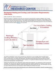
7 HVAC SIZING: Requirements .......................................................................................................................... 25<br />
8 CASE STUDIES: Alternative Methods of Construction ........................................................................ 31.<br />
Appendix A: References and More Information on <strong>Air</strong> Sealing ....................................................... 33<br />
Appendix B: Whole-House Mechanical Ventilation Code Note ...................................................... 35
BUILDING TECHNOLOGIES PROGRAM | AIR LEAKAGE GUIDE
INTRODUCTION:<br />
Basics of <strong>Air</strong> <strong>Leakage</strong><br />
AIR LEAKAGE GUIDE | BUILDING TECHNOLOGIES PROGRAM<br />
<strong>Air</strong> leakage control is an important but commonly misunderstood component of the<br />
energy efficient house. Tightening the structure with caulking and sealants has several<br />
positive impacts.<br />
A tight house will:<br />
>> Have lower heating bills due to less heat loss<br />
>> Have fewer drafts and be more comfortable<br />
>> Reduce the chance of mold and rot because moisture is less likely to<br />
enter and become trapped in cavities<br />
>> Have a better performing ventilation system<br />
>> Potentially require smaller heating and cooling equipment capacities.<br />
<strong>Air</strong> leakage is sometimes called infiltration, which is the unintentional or accidental<br />
introduction of outside air into a building, typically through cracks in the building envelope<br />
and through use of doors for passage. In the summer, infiltration can bring humid outdoor<br />
air into the building. Whenever there is infiltration, there is corresponding exfiltration<br />
elsewhere in the building. In the winter, this can result in warm, moist indoor air moving into<br />
cold envelope cavities. In either case, condensation can occur in the structure, resulting in<br />
mold or rot. Infiltration is caused by wind, stack effect, and mechanical equipment in the<br />
building (see Figure 1).<br />
Wind creates a positive pressure on the windward face and negative pressure on the<br />
non-windward (leeward) facing walls, which pulls the air out of the building. Wind causes<br />
infiltration on one side of a building and exfiltration on the other. Wind effects can vary by<br />
surrounding terrain, shrubs, and trees.<br />
1
2<br />
BUILDING TECHNOLOGIES PROGRAM | AIR LEAKAGE GUIDE<br />
The “stack effect” is when warm air moves upward in a building. This happens in summer and winter, but<br />
is most pronounced in the winter because indoor-outdoor temperature differences are the greatest. Warm<br />
air rises because it’s lighter than cold air. So when indoor air is warmer than the outdoor air, it escapes out<br />
of the upper levels of the building, through open windows, ventilation openings, or penetrations and cracks<br />
in the building envelope. The rising warm air reduces the pressure in the base of the building, forcing cold<br />
air to infiltrate through open doors, windows, or other openings. The stack effect basically causes air<br />
infiltration on the lower portion of a building and exfiltration on the upper part.<br />
Mechanical equipment such as fans and blowers causes the movement of air within buildings and through<br />
enclosures, which can generate pressure differences. If more air is exhausted from a building than is supplied,<br />
a net negative pressure is generated, which can induce unwanted airflow through the building envelope.<br />
Bathroom exhaust fans, clothes dryers, built-in vacuum cleaners, dust collection systems, and range hoods<br />
all exhaust air from a building. This creates a negative pressure inside the building. If the enclosure is<br />
airtight or the exhaust flow rate high, large negative pressures can be generated.<br />
Figure 1: Examples of infiltration. Image courtesy: <strong>Building</strong> Science Corporation, www.buildingscience.com
AIR LEAKAGE GUIDE | BUILDING TECHNOLOGIES PROGRAM<br />
CODES:<br />
New Code <strong>Air</strong> <strong>Leakage</strong> Requirements<br />
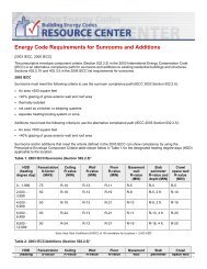
The 2012 IECC has several new<br />
requirements for verification of air sealing<br />
in new construction and additions.<br />
These new requirements apply to new<br />
construction, additions, and alterations<br />
where adopted by states and local<br />
jurisdictions. Furthermore, additional<br />
language was added to clarify that where<br />
there are conflicts or differences between provisions of the IECC and referenced codes,<br />
the IECC provisions must apply (Section R106, 2012 IECC).<br />
R106.1.2 Provisions in Referenced <strong>Codes</strong> and Standards<br />
Where the extent of the reference to a referenced code or standard includes subject<br />
matter that is within the scope of this code, the provisions of this code, as applicable,<br />
shall take precedence over the provisions in the referenced code or standard.<br />
Sealing the building thermal envelope has been required by the energy code for many years<br />
(editions of the IECC). However, in years past the provisions were somewhat vague and only<br />
required that areas of potential air leakage such as joints, seams, and utility penetrations be<br />
sealed with a durable material such as caulking, gasketing, or weather stripping. The 2009<br />
IECC required verification of air sealing by either a visual inspection against a detailed checklist<br />
or a whole-house pressure test. The 2012 IECC NOW requires all new construction and<br />
additions be both visually inspected and pressure tested as mandatory requirements. There<br />
have been some slight changes to the visual inspection checklist and ratcheting down of the<br />
testing parameters, requiring houses to be much tighter than the previous edition of the code<br />
(see Figure 2 and Table 1).<br />
For more information on<br />
the status of state code<br />
adoption, visit<br />
http://www.energycodes.gov/states/<br />
3
4<br />
BUILDING TECHNOLOGIES PROGRAM | AIR LEAKAGE GUIDE<br />
DEFINITIONS<br />
As defined according to<br />
2012 IECC:<br />
BUILDING<br />
Any structure used or intended<br />
for supporting or sheltering<br />
any use or occupancy,<br />
including any mechanical<br />
systems, service water heating<br />
systems and electric power<br />
and lighting systems located<br />
on the building site and<br />
supporting the building.<br />
BUILDING THERMAL<br />
ENVELOPE<br />
The basement walls, exterior<br />
walls, floor, roof, and any<br />
other building elements that<br />
enclose conditioned space or<br />
provide a boundary between<br />
conditioned space and exempt<br />
or unconditioned space.<br />
<strong>Air</strong> <strong>Leakage</strong> Map Graphic<br />
All of Alaska in Zone 7<br />
except for the following buroughs in Zone 8:<br />
• Bethel • Northwest Arctic<br />
• Dellingham • Southeast Fairbanks<br />
• Fairbanks N.Star • Wade Hampton<br />
• Nome • Yukon-Koyukuk<br />
• North Slope<br />
Figure 2: Climate zones (by county) for the 2012 IECC<br />
Climate Zone 2009 IECC 2012 IECC<br />
1 - 2 < 7 ACH
AIR LEAKAGE GUIDE | BUILDING TECHNOLOGIES PROGRAM<br />
PLANNING:<br />
<strong>Air</strong> Sealing Measures and Checklists<br />
The 2012 IECC provides a comprehensive list of components that must be sealed and inspected.<br />
However, unless the components are installed properly, passing the inspection and meeting the<br />
tested air leakage rate requirements may not be achievable without rebuilding some construction<br />
assemblies (such as gypsum board) that were previously installed. A good example is the air<br />
barrier between the ceiling (unconditioned attic) and conditioned space (living area). Since<br />
air leakage paths are driven by the fact that warm air rises, the attic is the largest area (square<br />
footage) of potential heat loss. Areas in the ceiling that might not have been sealed properly<br />
could include recessed cans, wires, pipes, attic access panels, drop down stair or knee wall doors<br />
and more. Figure 3 is a picture taken with an infrared camera illustrating where the temperature<br />
difference is and potential heat loss. The reds and purples indicate higher heat loss areas.<br />
Figure 3: <strong>Air</strong> <strong>Leakage</strong> Test Results<br />
Recessed Can<br />
Ceiling Plane<br />
5
6<br />
BUILDING TECHNOLOGIES PROGRAM | AIR LEAKAGE GUIDE<br />
DEFINITIONS<br />
As defined according to<br />
2012 IECC:<br />
AIR BARRIER<br />
Material(s) assembled and<br />
joined together to provide a<br />
barrier to air leakage through<br />
the building envelope. An air<br />
barrier may be a single material<br />
or combination of materials.<br />
CONTINUOUS AIR BARRIER<br />
A combination of materials<br />
and assemblies that restrict<br />
or prevent the passage of air<br />
through the building thermal<br />
envelope.<br />
R402.4.1.1 Installation<br />
The components of the building thermal envelope as<br />
listed in Table R402.4.1.1 shall be installed in accordance<br />
with the manufacturer’s instructions and the criteria<br />
listed in Table R402.4.1.1, as applicable to the method<br />
of construction. Where required by the code official an<br />
approved third party shall inspect all components and<br />
verify compliance.<br />
The IECC’s checklist covers not only air barriers but proper<br />
installation of insulation and other elements. In Table<br />
402.4.1.1, items that are directly related to air leakage and<br />
proper air barriers are highlighted in yellow.<br />
Even though the IECC checklist lists 14 specific components<br />
that are directly related to air barriers, more attention must<br />
be focused on all areas that have potential for air leakage.<br />
A good understanding of building science can facilitate<br />
proper air sealing. For example, <strong>Building</strong> America research<br />
identifies 19 key areas where air sealing can improve a home’s<br />
energy efficiency, comfort, and building durability.<br />
Common air sealing trouble spots are shown in Figure 4<br />
on page 8 and listed in the following table. Several of these<br />
trouble spots are described in more detail as highlighted in<br />
the <strong>Building</strong> America <strong>Air</strong> Sealing Checklist.<br />
Additional information on other trouble spots and other building science<br />
information can be found in the <strong>Building</strong> America Best Practices guides and<br />
<strong>Air</strong> <strong>Leakage</strong> guide available for free download at www.buildingamerica.gov.<br />
Builders, contractors, and/or designers should develop an air sealing strategy beginning with reviewing the<br />
building plans and identifying potential areas of air leakage. These checklists can be used to help identify<br />
the areas. The strategy also needs to include the types of materials that will be used to create<br />
an air barrier and seal the building envelope. The IECC does not identify specific products that must be<br />
used to create air barriers and seal the building envelope, but does require that the materials allow for<br />
expansion and contraction.
Table R402.4.1.1 (2012 IECC). <strong>Air</strong> Barrier and Insulation Installation*<br />
COMPONENT CRITERIA*<br />
AIR LEAKAGE GUIDE | BUILDING TECHNOLOGIES PROGRAM<br />
<strong>Air</strong> barrier and thermal barrier A continuous air barrier shall be installed in the building envelope.<br />
Exterior thermal envelope contains a continuous air barrier.<br />
Breaks or joints in the air barrier shall be sealed.<br />
<strong>Air</strong>-permeable insulation shall not be used as a sealing material.<br />
Ceiling/attic The air barrier in any dropped ceiling/soffit shall be aligned with the<br />
insulation and any gaps in the air barrier sealed.<br />
Access openings, drop down stair or knee wall doors to unconditioned<br />
attic spaces shall be sealed.<br />
Walls Corners and headers shall be insulated and the junction of the foundation<br />
and sill plate shall be sealed.<br />
The junction of the top plate and top of exterior walls shall be sealed.<br />
Exterior thermal envelope insulation for framed walls shall be installed in<br />
substantial contact and continuous alignment with the air barrier.<br />
Knee walls shall be sealed.<br />
Windows, skylights and doors The space between window/door jambs and framing and skylights and<br />
framing shall be sealed.<br />
Rim joists Rim joists shall be insulated and include the air barrier.<br />
Floors (including above-garage and<br />
cantilevered floors)<br />
Insulation shall be installed to maintain permanent contact with<br />
underside of subfloor decking.<br />
The air barrier shall be installed at any exposed edge of insulation.<br />
Crawl space walls Where provided in lieu of floor insulation, insulation shall be permanently<br />
attached to the crawl space walls.<br />
Exposed earth in unvented crawl spaces shall be covered with a Class I<br />
vapor retarder with overlapping joints taped.<br />
Shafts, penetration Duct shafts, utility penetrations and flue shafts opening to exterior or<br />
unconditioned space shall be sealed.<br />
Narrow cavities Batts in narrow cavities shall be cut to fit, or narrow cavities shall be filled<br />
by insulation that on installation readily conforms to the available cavity<br />
space.<br />
Garage separation <strong>Air</strong> sealing shall be provided between the garage and conditioned<br />
spaces.<br />
Recessed lighting Recessed light fixtures installed in the building thermal envelope shall be<br />
air tight, IC rated, and sealed to the drywall.<br />
Plumbing and wiring Batt insulation shall be cut neatly to fit around wiring and plumbing<br />
in exterior walls, or insulation that on installation readily conforms to<br />
available space shall extend behind piping and wiring.<br />
Shower/tub on exterior wall Exterior walls adjacent to showers and tubs shall be insulated and the air<br />
barrier installed separating them from the showers and tubs.<br />
Electrical/phone box on exterior walls The air barrier shall be installed behind electrical or communication<br />
boxes or air sealed boxes shall be installed.<br />
HVAC register boots HVAC register boots that penetrate building thermal envelope shall be<br />
sealed to the subfloor or drywall.<br />
Fireplace An air barrier shall be installed on fireplace walls. Fireplaces shall have<br />
gasketed doors.<br />
*In addition, inspection of log walls shall be in accordance with the provisions of ICC-400.<br />
7
8<br />
BUILDING TECHNOLOGIES PROGRAM | AIR LEAKAGE GUIDE<br />
Figure 4: <strong>Building</strong> America—air sealing trouble spots
Table 2. <strong>Building</strong> America <strong>Air</strong> Sealing Checklist<br />
<strong>Air</strong> Barrier Completion <strong>Guide</strong>lines<br />
AIR LEAKAGE GUIDE | BUILDING TECHNOLOGIES PROGRAM<br />
1. <strong>Air</strong> Barrier and Thermal Barrier Alignment <strong>Air</strong> Barrier is in alignment with the thermal barrier<br />
(insulation).<br />
2. Attic <strong>Air</strong> Sealing Top plates and wall-to-ceiling connections are sealed.<br />
3. Attic Kneewalls <strong>Air</strong> barrier is installed at the insulated boundary (kneewall<br />
transition or roof, as appropriate).<br />
4. Duct Shaft/Piping Shaft and Penetrations Openings from attic to conditioned space are sealed.<br />
5. Dropped Ceiling/Soffit <strong>Air</strong> barrier is fully aligned with insulation; all gaps are fully<br />
sealed.<br />
6. Staircase Framing at Exterior Wall/Attic <strong>Air</strong> barrier is fully aligned with insulation; all gaps are fully<br />
sealed.<br />
7. Porch Roof <strong>Air</strong> barrier is installed at the intersection of the porch roof<br />
and exterior wall.<br />
8. Flue or Chimney Shaft Opening around flue is closed with flashing, and any<br />
remaining gaps are sealed with fire-rated caulk or sealant.<br />
9. Attic Access/Pull-Down Stair Attic access panel or drop-down stair is fully gasketed for<br />
an air-tight fit.<br />
10. Recessed Lighting Fixtures are provided with air-tight assembly or covering.<br />
11. Ducts All ducts should be sealed, especially in attics, vented<br />
crawlspaces, and rim areas.<br />
12. Whole-House Fan Penetration at Attic An insulated cover is provided that is gasketed or sealed<br />
to the opening from either the attic side or ceiling side of<br />
the fan.<br />
13. Exterior Walls Service penetrations are sealed and air sealing is in place<br />
behind or around shower/tub enclosures, electrical<br />
boxes, switches, and outlets on exterior walls.<br />
14. Fireplace Wall <strong>Air</strong> sealing is completed in framed shaft behind the<br />
fireplace or at fireplace surround.<br />
15. Garage/Living Space Walls <strong>Air</strong> sealing is completed between garage and living<br />
space. Pass-through door is weather stripped.<br />
16. Cantilevered Floor Cantilevered floors are air sealed and insulated at<br />
perimeter or joist transition.<br />
17. Rim Joists, Seal Plate, Foundation, and Floor Rim joists are insulated and include an air barrier.<br />
Junction of foundation and sill plate is sealed.<br />
Penetrations through the bottom plate are sealed. All<br />
leaks at foundations, floor joists, and floor penetrations<br />
are sealed. Exposed earth in crawlspace is covered with<br />
Class I vapor retarder overlapped and taped at seams.<br />
18. Windows and Doors Space between window/door jambs and framing is<br />
sealed.<br />
19. Common Walls Between Attached Dwelling Units The gap between a gypsum shaft wall (i.e., common wall)<br />
and the structural framing between units is sealed.<br />
Items highlighted in yellow will be discussed in more detail.<br />
9
10<br />
BUILDING TECHNOLOGIES PROGRAM | AIR LEAKAGE GUIDE<br />
<strong>Air</strong> Barrier and Thermal Barrier Alignment<br />
Envelope <strong>Air</strong> Sealing<br />
Source: <strong>Building</strong> Science Corporation
Attic Kneewalls<br />
<strong>Air</strong> barrier is installed at the<br />
insulated boundary (kneewall<br />
transition or roof, as appropriate)<br />
Kneewalls, the sidewalls of finished<br />
rooms in attics, are often leaky and<br />
uninsulated. A contractor can insulate<br />
and air seal these walls in one step<br />
by covering them from the attic side<br />
with sealed rigid foam insulation. A<br />
contractor can plug the open cavities<br />
between joists beneath the kneewall<br />
with plastic bags filled with insulation<br />
or with pieces of rigid foam. Another<br />
option is to apply rigid foam to the<br />
underside of the rafters along the<br />
sloped roof line and air seal at the top of<br />
the kneewall and the top of the sidewall,<br />
which provides the benefit of both<br />
insulating the kneewall and providing<br />
insulated attic storage space.<br />
Doors cut into kneewalls should also be<br />
insulated and air sealed by attaching<br />
rigid foam to the attic side of the door,<br />
and using a latch that pulls the door<br />
tightly to a weather-stripped frame.<br />
AIR LEAKAGE GUIDE | BUILDING TECHNOLOGIES PROGRAM<br />
Figure 5. Insulate and air seal the<br />
kneewall itself, as shown, or along the<br />
roof line (Source: DOE 2000a).<br />
Figure 6. <strong>Air</strong> seal floor joist cavities<br />
under kneewalls by filling cavities<br />
with fiberglass batts that are rolled<br />
and stuffed in plastic bags (as shown<br />
here) or use rigid foam, Oriented<br />
Strand Board (OSB), or other air<br />
barrier board cut to fit and sealed at<br />
the edges with caulk.<br />
Figure 7. Build an airtight insulated<br />
box around any drawers or closets<br />
built into attic kneewalls that extend<br />
into uninsulated attic space. Insulate<br />
along air barrier (shown in yellow<br />
on drawing) or along roof line with<br />
rigid foam (Source: Iowa <strong>Energy</strong><br />
Center 2008).<br />
11
12<br />
BUILDING TECHNOLOGIES PROGRAM | AIR LEAKAGE GUIDE<br />
Dropped Ceiling/Soffit<br />
<strong>Air</strong> barrier is fully aligned with<br />
insulation; all gaps are fully sealed<br />
Soffits (dropped ceilings) found over<br />
kitchen cabinets or sometimes running<br />
along hallways or room ceilings as duct<br />
or piping chases are often culprits for air<br />
leakage. A contractor will push aside the<br />
attic insulation to see if an air barrier is<br />
in place over the dropped area. If none<br />
exists, the contractor will cover the area<br />
with a piece of rigid foam board, sheet<br />
goods, or reflective foil insulation that<br />
is glued in place and sealed along all<br />
edges with caulk or spray foam, then covered with attic insulation. If the soffit is on an exterior wall, sheet<br />
goods or rigid foam board should be sealed along the exterior wall as well. If the soffit contains recessed<br />
can lights, they should be rated for insulation contact and airtight or a dam should be built around them to<br />
prevent insulation contact.<br />
Figure 8. Place a solid air barrier over soffits as follows: pull back existing<br />
insulation; cover area with air barrier material (gypsum, plywood, OSB, rigid<br />
foam, etc.); seal edges with caulk; cover with insulation (Lstiburek 2010).<br />
Staircase Framing at Exterior Wall/Attic<br />
<strong>Air</strong> barrier is fully aligned with insulation; all gaps<br />
are fully sealed<br />
If the area under the stairs is accessible, look to see if<br />
the inside wall is finished. If not, have your contractor<br />
insulate it, if needed, and cover it with a solid sheet<br />
product like drywall, plywood, OSB, or rigid foam<br />
insulation. Then, your contractor can caulk the edges<br />
and tape the seams to form an air-tight barrier. Stairs<br />
should be caulked where they meet the wall.<br />
Figure 9. Install an air barrier and air sealing on exterior walls<br />
behind stairs. If the area behind the stairs is inaccessible, caulk<br />
stairs where they meet the wall. Use caulk if the area is already<br />
painted; use tape and joint compound if area will be painted.
Porch Roof<br />
<strong>Air</strong> barrier is installed at the intersection of the<br />
porch roof and exterior wall<br />
If a test-in inspection identifies air leakage at the<br />
wall separating the porch from the living space, the<br />
contractor will investigate to see if the wall board is<br />
missing or unsealed. If this is the case, the contractor<br />
will install some type of wall sheathing (oriented strand<br />
board, plywood, rigid foam board) cut to fit and sealed<br />
at the edges with spray foam. A contractor will also<br />
make sure this wall separating the attic from the porch<br />
is fully insulated.<br />
Figure 10. When researchers pulled back the porch ceiling, they found<br />
the wall board was missing so nothing was covering the insulation on<br />
this exterior wall. An air barrier of rigid foam board was put in place<br />
with spray foam (Image: Moriarta 2008).<br />
AIR LEAKAGE GUIDE | BUILDING TECHNOLOGIES PROGRAM<br />
Studies Show<br />
Steven Winter Associates, a <strong>Building</strong> America<br />
research team lead, used a blower door test<br />
and infrared cameras to investigate high-<br />
energy bill complaints at a 360-unit affordable<br />
housing development and found nearly twice the<br />
expected air leakage. Infrared scanning revealed<br />
an air leakage path on an exterior second-<br />
story wall above a front porch. Steven Winter<br />
Associates found that, while the wall between<br />
the porch and the attic had been insulated with<br />
unfaced fiberglass batts, wall board had never<br />
been installed. The insulation was dirty from<br />
years of windwashing as wind carried dust up<br />
through the perforated porch ceiling, through<br />
the insulation, into the attic and into the wall<br />
above. Crews used rigid foam cut to fit and glued<br />
in place with expandable spray foam to seal<br />
each area. Blower door tests showed the change<br />
reduced overall envelope leakage by 200 CFM 50.<br />
At a cost of $267 per unit, this fix resulted in<br />
savings of $200 per year per unit, for a payback<br />
of less than two years.<br />
13
14<br />
BUILDING TECHNOLOGIES PROGRAM | AIR LEAKAGE GUIDE<br />
Cantilevered Floor<br />
R402.4.1 <strong>Building</strong> thermal envelope<br />
Cantilevered floors are air sealed and insulated at<br />
perimeter or joist transitions<br />
Cantilevered floors, second-story bump-outs, and bay windows<br />
are another area in the home that often lacks proper air sealing.<br />
The floor cavity must be filled with insulation with good<br />
alignment (i.e., that is completely touching) the underside of<br />
the floor. The interior and exterior sheathing needs to be sealed<br />
at the framing edges. Blocking between floor joists should form<br />
a consistent air barrier between the cantilever and the rest<br />
of the house. Continuous sheathing, such as insulating foam<br />
sheathing, should cover the underside of the cantilever and be<br />
air sealed at the edges with caulk.<br />
Figure 11. Block and air seal both the floor-to-upper wall junction and the floorto-lower<br />
wall junction.<br />
The building thermal envelope shall comply with Sections R402.4.1.1 and R402.4.1.2. The sealing<br />
methods between dissimilar materials shall allow for differential expansion and contraction.<br />
The most common products for creating an airtight barrier are tapes, gaskets, caulks, and spray<br />
foam materials.<br />
Tapes<br />
To limit air leakage, builders use tapes to seal the seams of a variety of<br />
membranes and buildings products, including housewrap, polyethylene,<br />
OSB, and plywood. Tapes are also used to seal duct seams; seal leaks<br />
around penetrations through air barriers, for example, around plumbing<br />
vents, and sheet goods to a variety of materials, including concrete. No<br />
single tape works well in all of these applications, so builders, general<br />
contractors and trades need to familiarize themselves with the range of<br />
products and what will work best (time tested) and include these materials<br />
in the overall air barrier strategy. Image: Green<strong>Building</strong>Advisor.com
Gaskets can be Better than Caulk<br />
AIR LEAKAGE GUIDE | BUILDING TECHNOLOGIES PROGRAM<br />
When builders first learn about air sealing, they often depend heavily on caulk. After inspecting a home<br />
for leaks during a blower-door test, however, they learn that caulk has a few downsides. That’s when they<br />
usually graduate to gaskets.<br />
Typical locations for gaskets include between the:<br />
Spray Foams<br />
• Top of the foundation and the mudsill;<br />
• Subfloor and the bottom plate;<br />
• Window frame and the rough opening;<br />
• Bottom plate and the drywall; and<br />
• Top plate and the drywall.<br />
Spray foams are available in a variety of different forms, from small cans to<br />
larger industrial gallon sizes. Special care needs to be taken when using these<br />
products, as some expand more than others and some can exert significant<br />
pressure on the surrounding structure during expansion.<br />
Who is Responsible for <strong>Air</strong> Sealing?<br />
The IECC does not specify who is responsible for air sealing; it states that the building envelope shall<br />
be sealed in accordance with manufacturers’ instructions and the provisions (checklist) of the IECC.<br />
The construction documents for permitting to begin construction are typically submitted by the person<br />
in charge of the project and responsible for making sure all measures are installed properly and meet<br />
the provisions of the code. The inspector is responsible for making sure those measures meet code by<br />
verifying through on-site inspections.<br />
Since so many different areas of the building envelope must be sealed, the responsibility will not always<br />
be on one person, installer, or trade. For example, the mechanical contractor who installs the heating and<br />
cooling equipment most likely will not be installing an air barrier between the attic and conditioned space,<br />
as that is usually the responsibility of the insulation contractor.<br />
Image: Sprayfoam.com<br />
However, general contractors typically assume that the insulation and air sealing contractors seal and<br />
fill the holes, including filling any unintended holes that other subs leave behind. An air sealing strategy<br />
15
16<br />
BUILDING TECHNOLOGIES PROGRAM | AIR LEAKAGE GUIDE<br />
can include identifying who is responsible for sealing which building components, including unintended<br />
cracks or holes in the building thermal envelope.<br />
The following table is an example of building components to be sealed and who might be responsible for<br />
sealing those components.<br />
Table 3. <strong>Building</strong> components to be sealed and who might be responsible for sealing those components<br />
<strong>Building</strong> Components Contractor/Trade<br />
Ceiling/attic, kneewalls, attic access, recessed lighting,<br />
walls, floors, garage separation, electrical and service<br />
penetrations in ceiling, floors, and walls<br />
Service water piping, penetrations for water supply and<br />
demand<br />
Rim joists, sill plates, windows, skylights, doors, porch<br />
roof, shower/tub on exterior wall, electrical box on<br />
exterior wall, fireplace<br />
• Insulation/air sealing installers<br />
• Gypsum board contractors<br />
• Foundation contractors<br />
• Electricians<br />
• Roofers<br />
• Framers<br />
• General contractors<br />
• Plumbers<br />
• Electricians<br />
• Framers<br />
• Roofers<br />
• Plumbers<br />
• Electricians<br />
• Insulation/air sealing installers<br />
• Window and door installers<br />
• General contractors<br />
Ducts, piping, shafts, penetrations, register boots • HVAC installers<br />
All of the above • Inspectors<br />
• General contractors
TESTING:<br />
Requirements<br />
AIR LEAKAGE GUIDE | BUILDING TECHNOLOGIES PROGRAM<br />
The specific test requirements are based on the flow rate of air produced by a blower door<br />
at a specified pressure (50 pascals or 0.2 inches of water) when exterior doors are closed,<br />
dampers are closed but not otherwise sealed, exterior openings for continuous ventilation<br />
systems and heat recovery ventilators are closed but not sealed, HVAC systems are turned<br />
off, and duct supply and return registers are not covered or sealed.<br />
The infiltration rate is the volumetric flow rate of outside air into a building, typically in<br />
cubic feet per minute (CFM) or liters per second (LPS). The air exchange rate, (I), is the<br />
number of interior volume air changes that occur per hour, and has units of 1/h. The air<br />
exchange rate is also known as air changes per hour (ACH).<br />
ACH can be calculated by multiplying the building’s CFM by 60, then dividing by the<br />
building volume in cubic feet. (CFM x 60)/volume. The requirement is expressed in ACH,<br />
which takes account of the overall size (volume) of the home:<br />
Total air leakage < 3-5 ACH (air changes per hour)<br />
What is a blower door? It is a powerful fan that attaches and seals to a door (typically<br />
the entrance door to the home) and blows air into or out of the house to pressurize or<br />
depressurize the home. The inside-outside pressure difference will cause air to force its<br />
way through any cracks in the building thermal envelope. Measuring the flow rate at the<br />
specified test pressure indicates the leakiness of the envelope.<br />
17
18<br />
BUILDING TECHNOLOGIES PROGRAM | AIR LEAKAGE GUIDE<br />
Figure 12. Blower door<br />
During testing:<br />
Who Performs the Test and is Certification Required?<br />
The IECC does not specifically address who should perform the test.<br />
Builders, contractors, tradesmen, or code officials can perform the test.<br />
Code officials can also request the test be performed by an independent<br />
third party. The IECC does not require the person performing the test to be<br />
certified. However, it is recommended that the person be knowledgeable<br />
and have experience in using the equipment.<br />
R402.4.1.2 Testing<br />
RESNET and BPI provide certifications for<br />
whole-house testing. For more information<br />
go to www.resnet.org or www.bpi.org.<br />
The building or dwelling unit shall be tested and verified as having<br />
an air leakage rate not exceeding 5 air changes per hour in Climate<br />
Zones 1 and 2, and 3 air changes per hour in Climate Zones 3 through<br />
8. Testing shall be conducted with a blower door at a pressure of 0.2<br />
inches w.g. (50 pascals). Where required by the code official, testing<br />
shall be conducted by an approved third party. A written report of the<br />
results of the test shall be signed by the party conducting the test and<br />
provided to the code official. Testing shall be performed at any time<br />
after creation of all penetrations of the building thermal envelope.<br />
1. Exterior windows and doors, fireplace and stove doors shall be closed, but not sealed, beyond<br />
the intended weatherstripping or other infiltration control measures;<br />
2. Dampers including exhaust, intake, makeup air, backdraft and flue dampers shall be closed,<br />
but not sealed beyond intended infiltration control measures;<br />
3. Interior doors, if installed at the time of the test, shall be open;<br />
4. Exterior doors for continuous ventilation systems and heat recovery ventilators shall be closed<br />
and sealed;<br />
5. Heating and cooling systems, if installed at the time of the test, shall be turned off; and<br />
6. Supply and return registers, if installed at the time of the test, shall be fully open.
TESTING:<br />
Presenting Results<br />
AIR LEAKAGE GUIDE | BUILDING TECHNOLOGIES PROGRAM<br />
A permanently affixed certificate posted on or near the electrical panel is not a new<br />
requirement in the IECC. However, the information required on the certificate NOW includes<br />
results of duct and whole-house pressure tests in addition to the predominant R-values of<br />
insulation installed in or on ceiling/roof,<br />
walls, foundations, and ducts outside<br />
conditioned spaces; fenestration U-factors<br />
and solar heat gain coefficients (SHGCs);<br />
and efficiencies of heating, cooling, and<br />
service water heating equipment.<br />
As a recommendation for verification of<br />
testing, whomever performs the testing<br />
should also submit the test results to the<br />
building official and/or general contractor,<br />
confirming the air leakage levels have<br />
been met.<br />
R401.2 Certificate (Mandatory)<br />
A permanent certificate shall be<br />
completed and posted on or in<br />
the electrical distribution panel by<br />
the builder or registered design<br />
professional. The certificate shall list<br />
the results from any required duct<br />
system and building envelope air<br />
leakage testing done on the building.<br />
The illustration is an <strong>Energy</strong> Efficiency Certificate<br />
that can be created and printed using DOE’s <strong>Building</strong><br />
<strong>Energy</strong> <strong>Codes</strong> Program software called REScheck.<br />
www.energycodes.gov<br />
19
20<br />
BUILDING TECHNOLOGIES PROGRAM | AIR LEAKAGE GUIDE
VENTILATION:<br />
Requirements<br />
AIR LEAKAGE GUIDE | BUILDING TECHNOLOGIES PROGRAM<br />
Many building scientists believed mechanical ventilation should have been part of the<br />
building design even prior to the 2012 IECC. However, there are disagreements as to the<br />
level of envelope tightness at which mechanical ventilation is necessary due to health and<br />
safety concerns. This is no longer a question given the new air leakage requirements of the<br />
2012 IECC and other provisions in the International Residential Code (IRC) and International<br />
Mechanical Code (IMC). The 2012 IECC does not specifically address the requirements for<br />
whole-house mechanical ventilation, but it references the ventilation requirements of the<br />
IRC or IMC as a mandatory provision.<br />
IECC, R403.5 Mechanical Ventilation (Mandatory)<br />
The building shall be provided with ventilation that meets the requirements of the<br />
International Residential Code or International Mechanical Code, as applicable, or<br />
with other approved means of ventilation. Outdoor air intakes and exhausts shall have<br />
automatic or gravity dampers that close when the ventilation system is not operating.<br />
Both the 2012 IRC and IMC require mechanical ventilation when the air infiltration rate<br />
of the dwelling unit is < 5 ACH when tested with a blower door in accordance with the<br />
2012 IECC provisions.<br />
IRC, Section R303.4 Mechanical Ventilation<br />
Where the air infiltration rate of a dwelling unit is less than 5 air changes per hour<br />
when tested with a blower door at a pressure of 0.2 inch w.c. (50 Pa) in accordance<br />
with Section N1102.4.1.2, the dwelling unit shall be provided with whole-house<br />
ventilation in accordance with Section M1507.3.<br />
Section N1102.4.1.2 is the extraction of the air leakage requirements in the IECC,<br />
Section R402.4. ICC duplicated the language from the IECC residential provisions in the<br />
IRC, Chapter 11, <strong>Energy</strong> Efficiency.<br />
21
22<br />
BUILDING TECHNOLOGIES PROGRAM | AIR LEAKAGE GUIDE<br />
IMC, Section 401.2 Ventilation Required<br />
Where the air infiltration rate in a dwelling unit is less than 5 air changes per hour when tested<br />
with blower door at a pressure of 0.2-inch water column (to Pa) in accordance with Section<br />
402.4.1.2 of the International <strong>Energy</strong> Conservation Code, the dwelling unit shall be ventilated by<br />
mechanical means in according with Section 403.<br />
IECC, Section R403.5.1 Whole-House Mechanical Ventilation System Fan Efficacy<br />
Mechanical ventilation system fans shall meet the efficacy requirements of Table 403.5.1.<br />
Exception: Where mechanical ventilation system fans are integral to tested and listed HVAC<br />
equipment, they shall be powered by an electronically commutated motor.<br />
Table 4. 2012 IECC Table R403.5.1, Mechanical Ventilation System Fan Efficacy<br />
Fan Location <strong>Air</strong> Flow Rate Minimum<br />
(CFM)<br />
Minimum Efficacy<br />
(CFM/watt)<br />
<strong>Air</strong> Flow Rate Maximum<br />
(CFM)<br />
Range Hoods Any 2.8 Any<br />
In-line Fan Any 2.8 Any<br />
Bathroom, Utility Room 10 1.4 < 90<br />
Bathroom, Utility Room 90 2.8 Any<br />
In addition, ASHRAE Standard 62.2 provides guidance on the appropriate ventilation for acceptable<br />
indoor air quality in low-rise residential buildings. The standard specifies that forced ventilation is required<br />
in houses with a natural infiltration rate less than 0.35 ACH. This is typically accomplished with heat<br />
recovery ventilation or exhaust fans running constantly or periodically. The standard offers guidance for<br />
incorporating whole-house systems into a home. This standard is not referenced in the IECC, though some<br />
jurisdictions and states adopt this standard as part of their requirements.<br />
For more information on whole-house mechanical ventilation,<br />
refer to Appendix B.
Ventilation Systems<br />
AIR LEAKAGE GUIDE | BUILDING TECHNOLOGIES PROGRAM<br />
There are several options for mechanical ventilation systems. Spot ventilation, using exhaust-only fans in<br />
the kitchen and bathroom, removes water vapor and pollutants from specific locations in the home, but<br />
does not distribute fresh air. Balanced ventilation systems, such as air-to-air exchangers, heat-recovery<br />
ventilators, and energy recovery ventilators, both supply and exhaust air.<br />
Table 5: Pros and Cons of Various Mechanical Ventilation Systems<br />
Ventilation Type Pros Cons<br />
Exhaust Only<br />
<strong>Air</strong> is exhausted from the<br />
house with a fan<br />
Supply Only<br />
<strong>Air</strong> is supplied into the house<br />
with a fan<br />
Balanced <strong>Air</strong><br />
Exchange System<br />
Heat and energy recovery<br />
ventilators supply and<br />
exhaust air<br />
• Easy to install<br />
• Simple method for spot ventilation<br />
• Inexpensive<br />
• Does not interfere with combustion<br />
appliances<br />
• Positive pressures inhibit pollutants<br />
from entering<br />
• Delivers to important locations<br />
• No combustion impact<br />
• No induced infiltration/exfiltration<br />
• Can be regulated to optimize<br />
performance<br />
• Provides equal supply and exhaust air<br />
• Recovers up to 80% of the energy in air<br />
exchanged<br />
• Negative pressure may cause<br />
backdrafting<br />
• Makeup air is from random sources<br />
• Removes heated or cooled air<br />
• Does not remove indoor air pollutants<br />
at their source<br />
• Brings in hot or cold air or moisture<br />
from the outside<br />
• <strong>Air</strong> circulation can feel drafty<br />
• Furnace fan runs more often unless fan<br />
has an ECM (variable-speed motor)<br />
• More complicated design<br />
considerations<br />
• Over ventilation unless the building<br />
is tight<br />
• Cost<br />
23
24<br />
BUILDING TECHNOLOGIES PROGRAM | AIR LEAKAGE GUIDE<br />
Heat and <strong>Energy</strong> Recovery Ventilation Systems<br />
Heat recovery ventilators (HRVs) and energy recovery (or enthalpy recovery) ventilators (ERVs) both<br />
provide a controlled way of ventilating a home while minimizing energy loss by using conditioned exhaust<br />
air to warm or cool fresh incoming air. There are some small wall or window-mounted models, but the<br />
majority are central, whole-house ventilation systems that share the furnace duct system or have their<br />
own duct system. The main difference between an HRV and an ERV is the way the heat exchanger<br />
works. With an ERV, the heat exchanger transfers water vapor along with heat energy, while an HRV only<br />
transfers heat. The ERV helps keep indoor humidity more constant. However, in very humid conditions,<br />
the ERV should be turned off when the air conditioner is not running. <strong>Air</strong>-to-air heat exchangers or HRVs<br />
are recommended for cold climates and dry climates. ERVs are recommended for humid climates. Most<br />
ERV systems can recover about 70%–80% of the energy in the exiting air. They are most cost effective in<br />
climates with extreme winters or summers, and where fuel costs are high. ERV systems in cold climates<br />
must have devices to help prevent freezing and frost formation.<br />
Figure 13. Heat and energy recovery ventilators bring in fresh<br />
air, exhaust stale air, and save energy by transferring heat into<br />
incoming air through a heat exchanger (Ruud 2011).<br />
Figure 14. Semi-balanced ventilation systems provide fresh<br />
air and exhaust stale air but flow rates may not be balanced<br />
(Ruud 2011).
HVAC SIZING:<br />
Requirements<br />
AIR LEAKAGE GUIDE | BUILDING TECHNOLOGIES PROGRAM<br />
Reducing infiltration can reduce the loads on the building, which in turn can reduce the<br />
required sizes of the heating and cooling equipment. The 2012 IECC contains a mandatory<br />
requirement that equipment be sized according to <strong>Air</strong> Conditioning Contractors of America<br />
(ACCA) Manual S, based on loads calculated in accordance with ACCA Manual J (or other<br />
approved means of calculating the loads and equipment sizing). Many jurisdictions allow the<br />
use of other heating system sizing calculators. Builders/contractors should check with the<br />
governing jurisdiction to see what they accept. The builder or contractor will also need to make<br />
an assumption when calculating the loads based upon the tested air leakage rate (changes<br />
per hour at 50 pascals) of the home. Since the IECC requires
26<br />
BUILDING TECHNOLOGIES PROGRAM | AIR LEAKAGE GUIDE
AIR LEAKAGE GUIDE | BUILDING TECHNOLOGIES PROGRAM<br />
CASE STUDIES:<br />
Alternative Methods of Construction<br />
Some builders are currently building energy efficient homes in the cold and very cold<br />
climates that achieve the low air leakage rates specified in the 2012 IECC (
28<br />
BUILDING TECHNOLOGIES PROGRAM | AIR LEAKAGE GUIDE<br />
Table 6. Summary of <strong>Energy</strong> Efficiency Measures Incorporated in Case Study Homes in the Cold Climate<br />
Devoted Builders<br />
Kennewick, WA<br />
Project Mediterranean Villas<br />
Pasco, WA<br />
230 duplex and triplex units<br />
1,140 - 2,100 ft 2<br />
Market rate<br />
Tested <strong>Air</strong> <strong>Leakage</strong> and Sealing Tested at 0.8 to 2.0 ACH at 50 Pa;<br />
Spray foam ceiling deck<br />
Nelson Construction<br />
Farmington, CT<br />
Hamilton Way<br />
Farmington, CT<br />
10 single family homes<br />
2,960 - 3,540 ft 2<br />
Market rate<br />
Walls R-25 ICF 2x6 24-in. o.c.<br />
Tested at < 3.0 ACH at 50 Pa;<br />
Foam critical seal of rim and floor joists<br />
Wall Insulation R-25 ICF 2-inch foil-faced polyisocyanurate R-13<br />
sheathing, plus R-19 cellulose in stud<br />
cavities<br />
Attic Insulation R-49 blown-in cellulose on ceiling R-50 blown-in fiberglass on ceiling<br />
Foundation Insulation R-25 ICF perimeter foundation insulation<br />
with floating slab<br />
Ducts In conditioned space or in attic covered<br />
with spray foam and blown cellulose<br />
2-inch/R-10 XPS below slab; 2-inch/R-10<br />
XPS in thermomass basement walls<br />
In conditioned space in dropped ceiling or<br />
between joists<br />
<strong>Air</strong> Handler In conditioned space In conditioned basement<br />
HERS 54 - 68 53 - 54<br />
HVAC 8.5 HSPF/14 SEER heat pumps 94% AFUE gas furnace; SEER 14 air<br />
conditioner<br />
Windows U-0.29 U-0.32, SHGC-0.27, double-pane, low-e,<br />
vinyl framed<br />
Water Heating 84% EF tankless gas water heater 82% EF tankless gas water heater<br />
Ventilation <strong>Energy</strong> recovery ventilator Temperature- and timer-controlled fresh<br />
air intake; exhaust fan ducted to draw<br />
from main living space; transfer grilles<br />
Green 3-star BuiltGreen certified homes 2008 “Best <strong>Energy</strong> Efficient Green<br />
Community” by CT Home Builders<br />
Association; 2010 NAHB <strong>Energy</strong> Value<br />
Housing gold award<br />
Lighting and Appliances 70% hardwired CFL lighting; ENERGY<br />
STAR refrigerators, dishwashers, and<br />
clothes washers<br />
100% CFLs; optional appliances<br />
Solar No Optional 7-kW PV systems<br />
Verification 100% are third party tested and inspected,<br />
all homes met federal tax credit criteria<br />
since 2007<br />
All Builders Challenge certified<br />
AC = air conditioner; ACH = air changes per hour; AFUE = annual fuel utilization efficiency; CFL = compact fluorescent lights;<br />
Ef = energy factor; HERS = Home <strong>Energy</strong> Rating System; HSPF = Heating Seasonal Performance Factor; ICF = insulated concrete form;
AIR LEAKAGE GUIDE | BUILDING TECHNOLOGIES PROGRAM<br />
Table 6. Summary of <strong>Energy</strong> Efficiency Measures Incorporated in Case Study Homes in the Cold Climate (continued)<br />
Rural Development, Inc.<br />
Turner Falls, MA<br />
Wisdom Way Solar Village<br />
Greenfield, MA<br />
20 duplex units<br />
1,140 - 1,770 ft 2<br />
Affordable housing<br />
S&A Homes<br />
Pittsburgh, PA<br />
East Liberty Development, Inc.<br />
6 single-family urban infill<br />
3,100 ft 2<br />
Above market rate<br />
Tested at 1.1 to 1.5 ACH at 50 pa Tested at 3.0 ACH at 50 Pa; all<br />
penetrations and studs sealed<br />
Double walled (two 2x4 16-in. o.c. walls,<br />
5 inches apart)<br />
Shaw Construction<br />
Grand Junction, CO<br />
Burlingame Ranch Phase 1<br />
Aspen, CO<br />
84 units in 15 multi-family buildings<br />
1,325 ft 2<br />
Affordable<br />
Tested at 2.5 in 2 leakage<br />
per 100 ft 2 of envelope<br />
2x6 24-in. o.c. 2x6 24-in. o.c.<br />
R-42 dense-pack, dry blown cellulose R-24 blown fiberglass R-24 of 3.5” high-density spray foam<br />
R-50 blown-in cellulose on ceiling R-49 blown-in fiberglass on ceiling R-50 high-density foam at sloped roof,<br />
R-38 at flat roofs<br />
Full uninsulated basement with R-40<br />
blown cellulose under first floor<br />
Precast concrete basement walls with<br />
steel-reinforced concrete studs at 2.5 in.<br />
XPS R-12.5<br />
No ducts In conditioned space in open-web floor<br />
trusses<br />
Slab with R-13 XPS edge; some basements<br />
with R-13 interior polyisocyanurate; R-28<br />
of spray-foam insulation on ground under<br />
slab<br />
No ducts<br />
None In conditioned basement None<br />
8 - 18 51 - 55 54 - 62<br />
Small sealed-combustion 83% AFUE gasfired<br />
space heater on main floor; no AC<br />
Triple-pane U-0.18 on north/east/west<br />
sides; double-pane U-0.26 on south side<br />
Two-stage 96%-AFUE gas furnace with<br />
multi-speed blower; SEER-14 AC<br />
0.9 AFUE condensing gas boiler with<br />
baseboard hot water radiators<br />
U-0.33, SHGC-0.30, double-pane U-0.37, SHGC-0.33 fiberglass-framed,<br />
double-pane<br />
Solar thermal with tankless gas backup 82% EF tankless gas water heater Solar thermal with gas boiler back-up<br />
Continuous bathroom exhaust Passive fresh air duct to return plenum;<br />
fan-cycler on 50% of time for fresh air<br />
circulation, bath exhausts<br />
Heat-recovery ventilator<br />
LEED Platinum Meets LEED (not certified) LEED Certified<br />
100% CFLs; refrigerator, dishwasher 100% CFLs and ENERGY STAR<br />
refrigerator, dishwashers, and clothes<br />
washer<br />
2.8 to 3.4-kW PV; flat-plate collector solar<br />
thermal water heating<br />
90% CFL; ENERGY STAR refrigerator,<br />
dishwashers, clothes washers, ceiling fans<br />
No 10-kW PV on one building; solar hot water<br />
heating on all buildings<br />
All HERS rated All Builders Challenge certified All federal tax credit qualified<br />
o.c. = on center wood framed walls; Pa = pascals; PV = photovoltaic; SEER = Seasonal <strong>Energy</strong> Efficiency Ratio; SHGC = solar heat gain<br />
coefficient; XPS = extruded polystryene<br />
29
30<br />
BUILDING TECHNOLOGIES PROGRAM | AIR LEAKAGE GUIDE
CASE STUDIES/SUMMARY<br />
Devoted Builders, LLC<br />
AIR LEAKAGE GUIDE | BUILDING TECHNOLOGIES PROGRAM<br />
http://apps1.eere.energy.gov/buildings/publications/pdfs/building_america/<br />
ba_bp_devoted_cold.pdf<br />
Nelson Construction<br />
http://apps1.eere.energy.gov/buildings/publications/pdfs/building_america/<br />
ba_bp_nelson_cold.pdf<br />
Rural Development, Inc.<br />
http://apps1.eere.energy.gov/buildings/publications/pdfs/building_america/<br />
ba_bp_ruraldevelopment_cold.pdf<br />
S&A Home<br />
http://apps1.eere.energy.gov/buildings/publications/pdfs/building_america/<br />
ba_bp_sahomes_cold.pdf<br />
Shaw Construction<br />
http://apps1.eere.energy.gov/buildings/publications/pdfs/building_america/<br />
ba_bp_shaw_cold.pdf<br />
31
32<br />
BUILDING TECHNOLOGIES PROGRAM | AIR LEAKAGE GUIDE
APPENDIX A:<br />
References and More Information<br />
on <strong>Air</strong> Sealing<br />
AIR LEAKAGE GUIDE | BUILDING TECHNOLOGIES PROGRAM<br />
2012 IECC. 2012 International <strong>Energy</strong> Conservation Code, Section 402.4 “<strong>Air</strong> <strong>Leakage</strong>,” Section 403.5<br />
“Mechanical Ventilation,” International Code Council (ICC), Washington, DC. www.iccsafe.org/Store/Pages<br />
2012 IRC. 2012 International Residential Code, Section M 1507.3, R303.4, R403.5<br />
2010 ASHRAE, American Society of Heating, Refrigerating, and <strong>Air</strong> Conditioning Engineers, Atlanta, GA.<br />
ASHRAE Standard 62.2-2010<br />
<strong>Air</strong> Sealing: A <strong>Guide</strong> for Contractors to Share with Homeonwners - Volume 10, <strong>Building</strong> America, Pacific<br />
Northwest National Laboratory, Oakridge National Laboratory, PNNL-19284<br />
Builders Challenge <strong>Guide</strong> to 40% Whole-House <strong>Energy</strong> Savings in the Cold and Very Cold Climates,<br />
Volume 12, <strong>Building</strong> America Best Practices Series, February 2011, PNNL-20139<br />
<strong>Building</strong> Science Corporation 2009a. <strong>Air</strong> Barriers—Tub, Shower and Fireplace Enclosures. Information<br />
Sheet 407 for All Climates 5/20/2009, prepared by BSC for DOE’s <strong>Building</strong> America Program. http://<br />
www.buildingscience.com/documents/information-sheets/4-air-barriers/air-barriers2014tub- shower-and-<br />
fireplace-enclosures/?searchterm=building%20america<br />
<strong>Building</strong> Science Corporation 2009b. <strong>Air</strong> Sealing Windows. Information Sheet 406 for All Climates<br />
5/20/2009, prepared by BSC for DOE’s <strong>Building</strong> America Program. http://www.buildingscience.com/<br />
documents/information-sheets/4-air-barriers/sealing-air-barrier-penetrations/?searchterm=building%20<br />
america<br />
<strong>Building</strong> Science Corporation 2009c. Critical Seal (Spray Foam at Rim Joist). Information Sheet 408<br />
for All Climates 09/18/2009, prepared by BSC for DOE’s <strong>Building</strong> America Program. http://www.<br />
buildingscience.com/documents/information-sheets/4-air-barriers/info-408-critical-seal-spray-foam-at-<br />
rim-joist/?searchterm=building%20america<br />
33
34<br />
BUILDING TECHNOLOGIES PROGRAM | AIR LEAKAGE GUIDE<br />
<strong>Building</strong> Science Corporation 2009e. Sealing <strong>Air</strong> Barrier Penetrations, Information Sheet 405<br />
for All Climates 5/20/2009, prepared by BSC for DOE’s <strong>Building</strong> America Program. http://<br />
www.buildingscience.com/documents/information-sheets/4-air-barriers/sealing-air-barrier-<br />
penetrations/?searchterm=building%20america<br />
DOE – 2009a. Attic Access Insulation and <strong>Air</strong> Sealing. http://www.energysavers.gov/your_home/<br />
insulation_airsealing/index.cfm/mytopic=11400<br />
DOE – 2009b. <strong>Energy</strong> Savers: Sealing <strong>Air</strong> Leaks. www1.eere.energy.gov/consumer/tips/air_leaks.html<br />
DOE – 2009c. <strong>Energy</strong> Savers: Your Home - Weather Stripping. http://www.energysavers.gov/your_home/<br />
insulation_airsealing/index.cfm/mytopic=11280<br />
EPA – 2008a. A Do-It-Yourself <strong>Guide</strong> to Sealing and Insulating with ENERGY STAR. EPA, May 2008. http://<br />
www.energystar.gov/index.cfm?c=diy.diy_index www.energystar.gov/index.cfm?c=diy.diy_index<br />
EPA – 2008b. ENERGY STAR Qualified Homes Thermal Bypass Checklist <strong>Guide</strong>. http://www.energystar.<br />
gov/ia/partners/bldrs_lenders_raters/downloads/TBC_<strong>Guide</strong>_062507.pdf www.energystar.gov/ia/<br />
partners/bldrs_lenders_raters/downloads/TBC_<strong>Guide</strong>_062507.pdf<br />
EPA – 2009c. Sealing <strong>Air</strong> Leaks: Basement. http://www.energystar.gov/index.cfm?c=diy.diy_sealing_<br />
basement www.energystar.gov/index.cfm?c=diy.diy_sealing_basement<br />
EPA – 2010. Indoor airPLUS <strong>Building</strong> Professionals. http://www.epa.gov/indoorairplus/building_<br />
professionals.html www.epa.gov/indoorairplus/building_professionals.html<br />
Lstiburek, Joseph. 2010. <strong>Guide</strong> to Attic <strong>Air</strong> Sealing. Prepared for U.S. Department of <strong>Energy</strong> by <strong>Building</strong><br />
Science Corporation. www.buildingscience.com/documents/primers/guide-to-attic-air-sealing-with-<br />
details/?searchterm=air%20sealing<br />
Moriarta, Courtney. 2008. “Fixing <strong>Air</strong> <strong>Leakage</strong> in Connecticut Town Houses,” Home <strong>Energy</strong> Magazine. July/<br />
Aug 2008, p 28-30, www.swinter.com/news/documents/Fixing<strong>Air</strong><strong>Leakage</strong>.pdf&<br />
Rudd, Armin. 2011. Local Exhaust and Whole House Ventilation Strategies, Prepared by <strong>Building</strong> Science<br />
Corporation for the U.S. Department of <strong>Energy</strong>, http://www.buildingamerica.gov
APPENDIX B:<br />
Code Note<br />
Whole-House Mechanical Ventilation<br />
[ASHRAE 62.2-2010, 2012 IECC, 2012 IRC]<br />
PNNL-SA-83104<br />
ASHRAE Standard 62.2, Ventilation and Acceptable<br />
Indoor <strong>Air</strong> Quality in Low-Rise Residential <strong>Building</strong>s,<br />
defines the roles of and minimum requirements<br />
for mechanical and natural ventilation systems to<br />
achieve acceptable indoor air quality. This material<br />
supplements requirements contained in the national<br />
model energy codes with respect to mechanical<br />
ventilation systems. At this time, the residential<br />
provisions of the IECC do not reference ASHRAE 62.2.<br />
Ventilation<br />
The process of supplying outdoor air to or<br />
removing indoor air from a dwelling by natural or<br />
mechanical means. Such air may or may not have<br />
been conditioned.<br />
Mechanical Ventilation<br />
AIR LEAKAGE GUIDE | BUILDING TECHNOLOGIES PROGRAM<br />
The active process of supplying air to or removing air from an indoor space by powered equipment.<br />
Natural Ventilation<br />
Ventilation occurring as a result of only natural forces.<br />
CFM<br />
Cubic feet per minute, a standard measurement of airflow.<br />
In the past, no specific requirements for ventilation were imposed for residential buildings because leakage<br />
in envelope components and natural ventilation were considered adequate to maintain indoor air quality.<br />
As envelope construction practices have improved, the need to provide fresh air to homes via mechanical<br />
means has increased.<br />
35
36<br />
BUILDING TECHNOLOGIES PROGRAM | AIR LEAKAGE GUIDE<br />
ASHRAE Standard 62.2 provides guidelines for ventilation requirements. In addition to addressing whole-<br />
house ventilation, the standard also addresses local exhaust (kitchens and bathrooms) and criteria for<br />
mechanical air-moving equipment. Ventilation requirements for safety (including combustion appliances,<br />
adjacent space concerns, and location of outdoor air inlets) are also addressed.<br />
To comply with the ASHRAE standard, residential buildings (including manufactured homes) are required<br />
to install a mechanical ventilation system. An override control for the occupants is also required.<br />
Plan Review<br />
1. Confirm that a mechanical ventilation system that provides the appropriate ventilation rate (CFM) is<br />
called out. See ASHRAE 62.2-2010, Table 4.1a, for details.<br />
2. Check that the planned ventilation rate does not exceed 7.5 CFM per 100 ft 2 if located in a very cold<br />
climate or a hot, humid climate. See Tables 8.1 and 8.2 for details.<br />
3. Check that local exhaust systems for kitchens and bathrooms have been planned for appropriately.<br />
Field Inspection<br />
1. Confirm that a mechanical ventilation system that provides the appropriate ventilation rate (CFM)<br />
is installed.<br />
2. Confirm that occupant override control has been installed as required by ASHRAE 62.2-2010 section<br />
4.4, and 2012 IRC, section M1507.3.<br />
Code Citations*<br />
ASHRAE 62.2-2010, Table 4.1a (I-P) Ventilation <strong>Air</strong> Requirements, CFM<br />
[2012 IRC Table M1507.3.3(1) Continuous Whole-House Ventilation System <strong>Air</strong>flow Rate Requirements]<br />
Floor Area (ft 2 ) 0-1 Bedrooms 2-3 Bedrooms 4-5 Bedrooms 6-7 Bedrooms 7+ Bedrooms<br />
< 1,500 30 45 60 75 90<br />
1,500 - 3,000 45 60 75 90 105<br />
3,001 - 4,500 60 75 90 105 120<br />
4,501 - 6,000 75 90 105 120 135<br />
6,001 - 7,500 90 105 120 135 150<br />
> 7,500 105 120 135 150 165
ASHRAE 62.2-2010, Table 8.1 Hot, Humid U.S. Climates<br />
AIR LEAKAGE GUIDE | BUILDING TECHNOLOGIES PROGRAM<br />
Mobile, AL Savannah, GA Wilmington, NC<br />
Selma, AL Valdosta, GA Charleston, SC<br />
Montgomery, AL Hilo, HI Myrtle Beach, SC<br />
Texarkana, AR Honolulu, HI Austin, TX<br />
Apalachicola, FL Lihue, HI Beaumont, TX<br />
Daytona, FL Kahului, HI Brownsville, TX<br />
Jacksonville, FL Baton Rouge, LA Corpus Christi, TX<br />
Miami, FL Lake Charles, LA Dallas, TX<br />
Orlando, FL New Orleans, LA Houston, TX<br />
Pensacola, FL Shreveport, LA Galveston, TX<br />
Tallahassee, FL Biloxi, MS San Antonio, TX<br />
Tampa, FL Gulfport, MS Waco, TX<br />
Jackson, MS<br />
ASHRAE 62.2-2010, Table 8.2 Very Cold U.S. Climates<br />
Anchorage, AK Marquette, MI Fargo, ND<br />
Fairbanks, AK Sault Ste. Marie, MI Grand Forks, ND<br />
Caribou, ME Duluth, MN Williston, ND<br />
International Falls, MN<br />
2012 IECC, Section R403.5 Mechanical ventilation (Mandatory)<br />
The building shall be provided with ventilation that meets the requirements of the International Residential<br />
Code or International Mechanical Code, as applicable, or with other approved means of ventilation.<br />
Outdoor air intakes and exhausts shall have automatic or gravity dampers that close when the ventilation<br />
system is not operating.<br />
2012 IRC, Section R303.4 Mechanical ventilation<br />
Where the air infiltration rate of a dwelling unit is less than 5 air changes per hour when tested with a<br />
blower door at a pressure of 0.2 inch w.c. (50 Pa) in accordance with Section N1102.4.1.2, the dwelling unit<br />
shall be provided with whole-house ventilation in accordance with Section M1507.3.<br />
37
38<br />
BUILDING TECHNOLOGIES PROGRAM | AIR LEAKAGE GUIDE<br />
2012 IRC, Section M1507.3 Whole-house mechanical ventilation system<br />
Whole-house mechanical ventilation systems shall be designed in accordance with Sections M1507.3.1<br />
through M1507.3.3.<br />
M1507.3.1 System design<br />
The whole-house ventilation system shall consist of one or more supply or exhaust fans, or a<br />
combination of such, and associated ducts and controls. Local exhaust or supply fans are permitted<br />
to serve as such a system. Outdoor air ducts connected to the return side of an air handler shall be<br />
considered to provide supply ventilation.<br />
M1507.3.2 System controls<br />
The whole-house mechanical ventilation system shall be provided with controls that enable manual<br />
override.<br />
M1507.3.3 Mechanical ventilation rate<br />
The whole-house mechanical ventilation system shall provide outdoor air at a continuous exchange<br />
rate of not less than that determined in accordance with Table M1507.3.3(1).<br />
Exception: The whole-house mechanical ventilation system is permitted to operate intermittently<br />
where the system has controls that enable operation for not less than 25-percent of each 4-hour<br />
segment and the ventilation rate prescribed in Table M1507.3.3(1) is multiplied by the factor determined<br />
in accordance with Table M1507.3.3(2).2012.<br />
Table 7.4. 2012 IRC Table M1507.3.3(2) Intermittent Whole-House Mechanical Ventilation Rate Factors<br />
Run-Time Percentage in<br />
Each 4-Hour Segment<br />
25% 33% 50% 66% 75% 100%<br />
Factor 4.0 3.0 2.0 1.5 1.3 1.0<br />
*Copyright 2010. American Society of Heating, Refrigerating, and <strong>Air</strong> Conditioning Engineers, Atlanta, GA. ASHRAE<br />
Standard 62.2-2010. Reproduced with permission. All rights reserved.<br />
*Copyright 2011.International Code Council, Inc. Falls Church, Virginia. Reproduced with permission. All rights reserved.<br />
2012 International <strong>Energy</strong> Conservation Code.<br />
*Copyright 2011. International Code Council, Inc. Falls Church, Virginia. Reproduced with permission. All rights reserved.<br />
2012 International Residential Code.