Submarine cable laying and repairing
Submarine cable laying and repairing
Submarine cable laying and repairing

Create successful ePaper yourself
Turn your PDF publications into a flip-book with our unique Google optimized e-Paper software.
%f<br />
h<br />
ZU Institution of €kctrical engineers.<br />
Session 1909— 10.<br />
Students' Premium<br />
AWARDED TO<br />
W. H. YOUNG. 5:<br />
m m<br />
! ID<br />
i a<br />
S r-=l<br />
sm<br />
|CD<br />
io<br />
V. •<br />
/•
SUBMARINE CABLE LAYING<br />
AND REPAIRING.<br />
BY<br />
H. D. W^ILKINSON,<br />
Member of the Institution of EJlectrical Engineers, Member of the Institution<br />
of Mechanical Engineers, Consulting <strong>and</strong> Inspecting Engineer, I,ate<br />
Electrician in the Eastern Extension Telegraph Company,<br />
Ivate Engineer to the Executive of the Royal Commission<br />
for the Naval Exhibition, Chelsea,<br />
<strong>and</strong> the Columbian Exhibition,<br />
Chicago, U.S.A.<br />
Author of " Electric Tramvsrays in the United States <strong>and</strong> Canada,"<br />
" Electric Lifts," &c.. Joint Author with Dr. A. E. Kennelly<br />
of "Practical Notes for Electrical Students,"<br />
&c., &c.<br />
NEW AND COMPLETELY REVISED EDITION.<br />
LONDON<br />
THE ELECTRICIAN' PRINTING AND PUBLISHING<br />
LIMITED,<br />
Salisbury Court, Fleet Street, E.C,<br />
New York : The D. Van Nostr<strong>and</strong> Co., 23, Murray Sf<br />
Japan : Z. P, Maruya & Co., 14, Nihonbashi Tori SafidJUi<br />
India<br />
Thacker, Spink & Co., Calcutta. ^<br />
Higginbotham & Co., Madras. (f^<br />
[All Mights Heserved.J<br />
:
Printed <strong>and</strong> Published by<br />
'THE ELECTRICIAN" PRINTING AND PUBLISHING CO.<br />
1, 2 <strong>and</strong> 3, Salisbury Court, Fleet Street.<br />
London, E.G.
I<br />
PREFACE TO FIRST EDITION.<br />
HAVE endeavoured in this treatise to give a<br />
detailed technical summary of modern practice in<br />
Manufacturing, Laying, Testing <strong>and</strong> Repairing a<br />
<strong>Submarine</strong> Telegraph Cable. The testing section <strong>and</strong><br />
details of boardship practice have been prepared with<br />
the object <strong>and</strong> hope of helping men in the <strong>cable</strong> services<br />
who are looking further into these branches.<br />
The subject is one of very great interest, <strong>and</strong> few who<br />
are engaged in it are not sincere lovers of their profes-<br />
sion. The most exact scientific processes are called<br />
into ordinary use, <strong>and</strong> the service affords great scope for<br />
the exercise of engineering <strong>and</strong> electrical skill. The<br />
enterprise has a great deal before it as regards possi-<br />
bilities in research, improvements in instruments, pro-<br />
cesses <strong>and</strong> methods of working, <strong>and</strong> further extension<br />
of the <strong>cable</strong> systems. The description of the equipment<br />
of <strong>cable</strong> ships <strong>and</strong> the mechanical <strong>and</strong> electrical work<br />
carried on during the <strong>laying</strong> <strong>and</strong> <strong>repairing</strong> of a sub-<br />
marine <strong>cable</strong> will, I hope, prove also to some not directly<br />
engaged in the profession, but nevertheless interested in<br />
the enterprise, a means of informing themselves as to the<br />
work which has to be done from the moment a new<br />
<strong>cable</strong> is projected until it is successfully laid <strong>and</strong> worked.<br />
Although the days of popular enthusiasm <strong>and</strong> local<br />
stir in connection with <strong>cable</strong> expeditions are well nigh
iv.<br />
PREFACE.<br />
past, 1 think there will ever remain amongst the intelli-<br />
gent public feelings of admiration for these great enter-<br />
prises of the sea, <strong>and</strong> more than ordinary interest in<br />
the ships <strong>and</strong> men engaged in the great business of<br />
<strong>laying</strong> <strong>and</strong> maintaining these lines of human communi-<br />
cation between distant portions of the globe.<br />
The first portions of this work were published as<br />
articles in The Electrician, commenced soon after my<br />
return from the Cape in 1891. Since that date the<br />
continuation of the work has only been possible at very<br />
short intervals of leisure, <strong>and</strong> was laid aside altogether<br />
during ten month's professional engagement in America<br />
in 1893. The work has, however, generally been<br />
brought up to date.<br />
The improvements in the Thomson Syphon Recorder,,<br />
human relay, duplex working, <strong>and</strong> automatic trans-<br />
mitters have not been dealt with in this work, as these<br />
matters cover a very wide field, <strong>and</strong> are more adapted<br />
for separate treatment.<br />
I have now the pleasant duty of thanking the many<br />
friends who have rendered me valuable suggestions <strong>and</strong><br />
assistance in this work, <strong>and</strong> thus supplemented my own<br />
experience in <strong>cable</strong> work in the Far East, which forms<br />
the groundwork of this treatise. I thank most cordially,<br />
for their assistance to me in various ways, Sir W. H.<br />
Preece, C.B., F.R.S., Mr. A. E. Kennelly, Mr. Edward<br />
Stallibrass, F.R.G.S., Mr. F. C. Webb, Mr. A. C M.<br />
Weaver, Mr. H. K. C. Fisher, Mr. Geo. E. Cole, Mr.<br />
F. C. H. Sinclair, Mr. Robert K. Gray, Mr. Matthew<br />
Gray,Mr. E. Raymond-Barker, Mr.Chas. Bright, F.R.S.E.,<br />
Mr. R. London, Mr. H. Clifford, Mr. Herbert Taylor, Mr.<br />
R. H. Tonking, Mr. W. R. Culley, <strong>and</strong> others whose<br />
names are mentioned in the text of the book. I tender my<br />
thanks also to the following Companies <strong>and</strong> Firms for
PREFACE.<br />
supplying me with illustrations <strong>and</strong> various information<br />
:—Messrs. Siemens Bros, <strong>and</strong> Co., Woolwich ; The<br />
India-Rubber, Gutta Percha <strong>and</strong> Telegraph Works<br />
Company, Silvertown ;<br />
Maintenance Company, Greenwich ;<br />
The Telegraph Construction <strong>and</strong><br />
Messrs. Johnson &<br />
Phillips, Old Charlton ; Messrs. Elliott Bros., London ;<br />
The Eastern. Eastern Extension, <strong>and</strong> Eastern <strong>and</strong> South<br />
African Telegraph Companies, the Commercial Cable<br />
Company, &c.<br />
Wimbledon, June, 1896.<br />
H. D. Wilkinson.<br />
a2<br />
V.
PREFACE TO SECOND EDITION.<br />
THIS<br />
work has proved itself useful, <strong>and</strong> a second edition<br />
has become necessary. From time to time it has<br />
much gratified me to hear of the assistance derived<br />
from it by many of my friends in the Cable Service <strong>and</strong> also<br />
by that increasingly large world taking interest in <strong>cable</strong><br />
affairs.<br />
Mention has been made of the names <strong>and</strong> work of some<br />
of the early pioneers, but not to the extent I should have<br />
desired had the limits of the book permitted. To treat this<br />
subject adequately would necessarily involve the history of<br />
submarine telegraphy, which is sufficiently great in itself to<br />
require separate h<strong>and</strong>ling, <strong>and</strong>, moreover, is already to be<br />
found in several works <strong>and</strong> Papers. I trust, however, that<br />
sufficient reference has been made to those who started <strong>and</strong><br />
developed the industry to show that their names <strong>and</strong> per-<br />
sonality are ever cherished in the highest esteem.<br />
One of the earliest pioneers has recently passed from<br />
amongst us, the impress of whose genius <strong>and</strong> marvellous<br />
powers stamped itself from the beginning <strong>and</strong> for all time<br />
upon every stage in the development of submarine <strong>cable</strong><br />
telegraphy. While this branch of applied science owed so<br />
much to Lord Kelvin's inspiration <strong>and</strong> the many indispen-<br />
sable devices <strong>and</strong> instruments of his creation it stood in but<br />
small proportion to his brilliant work in the wider sphere
Vm. PREFACE.<br />
of applied electrical science <strong>and</strong> those deeper researches<br />
into the mysteries of Nature which almost incessantly<br />
throughout a life replete with superabundant labours<br />
exercised his transcendent powers.<br />
Since the first issue of this work also there has passed from<br />
us a great name <strong>and</strong> personality revered the world over <strong>and</strong><br />
but for whom submarine telegraphy would probably have<br />
been set back a generation. At a time when eight years of<br />
failures had culminated in the parting of the '65 Atlantic<br />
<strong>and</strong> alienated the sympathetic co-operation of the Govern-<br />
ment <strong>and</strong> public, Sir John Pender, with characteristic<br />
courage <strong>and</strong> confidence, saved the situation by a guarantee<br />
of means for a fresh effort, subsequently, as everyone knows,<br />
crowned by the successful completion of the '66 <strong>cable</strong>, <strong>and</strong><br />
recovery of the '65 by Sir James Anderson. From that<br />
moment the practicability of ocean telegraphy was assured,<br />
<strong>and</strong>, under the guidance of Sir John Pender's unique<br />
powers of administration, a vast industry arose, the benefits<br />
of which to mankind can never be fully known.<br />
,<br />
Great <strong>and</strong> remarkable technical progress has been made,<br />
<strong>and</strong> the <strong>cable</strong> electrician <strong>and</strong> engineer to-day has vastly<br />
more facilities to h<strong>and</strong> than ever before, giving him the<br />
advantage of working from a higher platform than his pre-<br />
decessors, <strong>and</strong> stimulating him to carry still further such<br />
developments <strong>and</strong> improvements as shall be to the general<br />
advantage <strong>and</strong> progress of the industry.<br />
I have devoted a great amount of time <strong>and</strong> pains in ihi<br />
endeavour to make the testing section useful. The deri-<br />
vation of all new formulae are given in full, as it is always<br />
desirable in performing a test to underst<strong>and</strong> the reasons<br />
underlying <strong>and</strong> supporting it ; but in order to facilitate<br />
easy reference the formulae themselves are in larger type<br />
so that they can be instantly distinguished.<br />
Since the first publication of this work 12 years ago, several<br />
specialised works on different branches of the subject have<br />
,
appeared. Mr. Charles Bright, F.R.S.E., has written valuable<br />
works on the History, Construction, Laying <strong>and</strong> Working of<br />
<strong>Submarine</strong> Cables, amongst which may be mentioned " Sub-<br />
marine Telegraphs," " The Evolution of the <strong>Submarine</strong><br />
Telegraph," " The Story of the Atlantic Cable " <strong>and</strong> " The<br />
Life Story of Sir Charles Tilston Bright," the latter written<br />
conjointly with Mr. Edward Brailsford Bright, <strong>and</strong> con-<br />
taining much information upon the pioneer stages of the<br />
enterprise, particularly of the <strong>laying</strong> of the first Atlantic<br />
<strong>and</strong> the first telegraph to India. Mr. Bright based<br />
the first-named volume partly upon the valuable work of<br />
Mons. E. Wiinschendorff in the French language, entitled<br />
" Traite de Telegraphie Sous-Marine," well known <strong>and</strong><br />
appreciated as the first complete work on <strong>Submarine</strong> Tele-<br />
graphy.<br />
Mr. J. Elton Young's able work, entitled " Electrical<br />
Testing for Telegraph Engineers," is a most valuable addi-<br />
tion on the subject of Electrical Testing <strong>and</strong> Localisation<br />
of Faults. Also the very practical treatise by Messrs.<br />
H. K. C. Fisher <strong>and</strong> J. C, H. Darby, entitled the " Students'<br />
Guide to <strong>Submarine</strong> Cable Testing," has, by its clearness of<br />
style <strong>and</strong> the experience the authors have brought to bear<br />
upon their work, proved itself of great service. In this<br />
special branch Mr. G. M. Baines " Beginners' Manual of<br />
<strong>Submarine</strong> Cable Testing <strong>and</strong> Working," has proved a very<br />
useful book <strong>and</strong> Mr. H. R. Kempe's " H<strong>and</strong>book of Elec-<br />
trical Testing " always remains as the st<strong>and</strong>ard work.<br />
Many valuable contributions to general knowledge on<br />
the subject of Testing have appeared in the pages of<br />
The Electrician <strong>and</strong> The Electvical Review, from the pen of<br />
Dr. A. E. Kennelly, Mr. J. Elton Young, Mr. C. W. Schaefer,<br />
the late Mr.W. J. Murphy, Mr. Arthur Dearlove, Mr. J.<br />
Rymer-Jones, Mr. E. Raymond-Barker, Mr. H. E. Cann<<br />
Mr. R. R. Black <strong>and</strong> other Authors, most of which I have<br />
taken due notice of in the present revision.
X, PEEFACE.<br />
I heartily thank the reviewers of the first edition for<br />
indicating the points in which this work needed improve-<br />
ment. I have consulted from time to time the above<br />
mentioned st<strong>and</strong>ard works on Testing <strong>and</strong> duly acknow-<br />
ledged the same in the body of the book. I am also<br />
grateful to many personal friends from whom I have had<br />
the advantage of suggestions at various times, <strong>and</strong> to Mr.<br />
P. Burrell, of the Eastern Telegraph Company, who aided<br />
me <strong>and</strong> pointed out the manner in which the testing<br />
section could be made most useful to those qualifying for<br />
the various grades in the service.<br />
In its present form, if this work shall help to maintain<br />
<strong>and</strong> foster the desire for progress <strong>and</strong> development <strong>and</strong><br />
prove of assistance to those who are endeavouring to attain<br />
greater efficiency in this interesting art, I shall always have<br />
the satisfaction of knowing that my labours have not been<br />
in vain.<br />
4, Queen Street Place, London, E.G.,<br />
August, ic<br />
H. D. Wilkinson.
Selection of Route<br />
Soundings<br />
Tubes <strong>and</strong> Sinkers<br />
Original Silvertown Machine<br />
TABLE OF CONTENTS.<br />
CHAPTER I.—SxjkveyingJthe Route<br />
Lucas' Sounding Machines ...<br />
Johnson <strong>and</strong> Phillips' Sounding Machine<br />
Lucas' Snapper<br />
Observing Sea Temperature <strong>and</strong> Pressure<br />
Ship's Position <strong>and</strong> Speed ...<br />
Thomson's Tubes<br />
James' <strong>Submarine</strong> Sentry ...<br />
CHAPTER 11.<br />
—<br />
Pbinciples of Design <strong>and</strong> Constrtjction.<br />
Principles of Design ... ... ... ... ... ... ... 37<br />
Speed of Signalling ... ... ... ... ... ... ... 38<br />
Speed Constant ... ... ... ... ... ... ... 41<br />
Temperature Variation of Copper ... ... ... ... ... 44<br />
Pressure Variation of Gutta Percha ... ... ... ... 47<br />
Temperature Variation of Gutta Percha ... ... ... ... 47<br />
Quality of Gutta Percha ... ... ... ... ... ... 49<br />
Weights of Copper <strong>and</strong> Gutta Percha ... ... ... ... 51<br />
Capacity per Naut ... ... ... ... ... ... ... 54<br />
Core Dimensions ... ... ... ... ... ... ... 59<br />
Best Proportions of Copper <strong>and</strong> Gutta Percha 60<br />
Clark's Segmental Conductor ... ,,. ... ... ... 62<br />
Siemens Solid Str<strong>and</strong> Conductor ... ... ... ... ... 63<br />
Conductivity Measurements ... ... ... ... ... ... 64<br />
Temperature Coefficient for Gutta Percha ... ... ... 68<br />
Collection <strong>and</strong> Supplies of Gutta Percha ... ... 69<br />
Species of Gutta Percha (Charles Bright, F.R.S.E.) 70<br />
Preparation of Gutta Percha ... ... ... ... ... 71<br />
Protection against Teredo ... ... ... ... ... ... 72<br />
Bright <strong>and</strong> Clark's Compound ... ... ... ... ... 72<br />
Sheathing <strong>and</strong> Outer Serving ... ... ... ... ... 73<br />
Tensile Strength of Sheath ... ... ... ... 75<br />
1<br />
2<br />
4<br />
9<br />
12<br />
16<br />
18<br />
20<br />
29<br />
33<br />
34
—<br />
XU. TABLE OF CONTENTS.<br />
CHAPTER II. Principles or Design <strong>and</strong> Constefction.<br />
Continued. page<br />
Specific Gravity of Cable ... ... ... ... ... ... 76<br />
Types of Cable 81<br />
Shore Ends 84<br />
Air-space Cable ... ... ... ... ... ... ... 87<br />
Core Manufacture ... ... ... ... ... ... ... 89<br />
Core Tests in Factory ... ... ... ... ... ... 90<br />
Brass Taping of Core ... ... ... ... ... ... 90<br />
Core-serving Machine ... ... ... ... ... ... 91<br />
Sheathmg Machines 93, 104<br />
Welding of Sheathing Wires ... ... ... ... ... 97<br />
Outer-serving Machine ... ... ... ... ... ... 101<br />
Factory Tanks 103<br />
Joint Tests 105<br />
Lay of Sheathing Wires ... ... ... ... ... ... 107<br />
CHAPTER III.<br />
—<br />
The Laying op Submarinb Cables.<br />
Order of Shipping 109, 116<br />
Selection of L<strong>and</strong>ing Place ... ... ... ... ... ... 109<br />
Distribution of Types Ill<br />
Stowing Cable in Ship's Tanks 112<br />
Order of Laying Cable ... ... ... ... ... ... 114<br />
CoUing in Tank 117<br />
L<strong>and</strong>ing Shore End 119<br />
Lighter for Paying Out ... ... ... ... ... ... 120<br />
L<strong>and</strong>ing Shore End from Ship 127<br />
Balloon Buoy 128<br />
Laying Main Cable ... ... ... ... ... ... ... 132<br />
Equipment of the " Dacia " ... ... ... ... ... 133<br />
Paying-out Brake 136<br />
Siemens Slack Indicator 139<br />
Cable-<strong>laying</strong> Ships 141<br />
Picking up Gear 148<br />
Dynamometer ... ... ... ... ... ... ... ... 149<br />
Atlantic Cables ... ... ... ... ... ... ... 151<br />
Tests during Laying ... ... ... ... ... ... ... 152<br />
Kelvin's Marine Galvanometer 161<br />
Buoy Operations 169<br />
Cable House <strong>and</strong> L<strong>and</strong>line 171<br />
Lightning Guards 177<br />
Final Tests 181<br />
CHAPTER IV.—The Cable Ship on Repairs.<br />
Speaking Apparatus 183<br />
Mirror Damping Devices ... ... ... ... ... ... 188<br />
The Mark Buoy 191<br />
Mushroom Anchor ... ... ... ... ... 192
CHAPTER IV.<br />
—<br />
TABLE OF CONTENTS. XUl.<br />
The Cable Ship on Repairs.—Continued.<br />
PAGE<br />
Grapnels <strong>and</strong> Grappling 192<br />
Buoying a Bight ... ... ... ... ... ... ... 210<br />
Dynamometers... ... ... ... ... ... ... ... 213<br />
Cable at Bows 219<br />
Buoying Cable 221<br />
Rotometer 228<br />
Picking Up Cable 230<br />
Capacity of Tanks ... ... ... ... ... ... ... 235<br />
Picking-up Gear<br />
241<br />
Removal of Fault 262<br />
Joint in Core ... ... ... ... ... ... ... ... 270<br />
Cable Splice , 276<br />
Slipping Splice<br />
Cable Stoppers... ... ... ... ... ... ... ... 288<br />
Paying Out 293<br />
Buoyed End Inboard... ... ... ... ... ... ... 303<br />
Slipping Final Splice 312<br />
Repair Sheets <strong>and</strong> Splice List ... ... ... ... ... 314<br />
Regulations for Cable Ships 320<br />
Cable Ships 321<br />
Cable Depots 349<br />
Hauling Machines ... ... ... ... ... ... ... 355<br />
Shore End Repairs ... ... ... ... ... ... ... 356<br />
CHAPTER V.<br />
The Localisation of Breaks <strong>and</strong> Faults.<br />
Cable Currents 364<br />
Balancing to False Zero 367<br />
Polarisation of Fault or Break 368<br />
The MUammeter 369<br />
Sullivan Universal Galvanometer ... ... ... ... ... 373<br />
Universal Shunts ... ... ... ... ... ... ... 381<br />
Breaks, <strong>and</strong> Similar Exposures ... ... ... ... ... 392<br />
Kennelly's Two-current Test ... ... ... ... ••• 394<br />
Kennelly's Three-current Test ... ... ... ... ... 403<br />
Rymer-Jones Two- current Test ... ... ... ... ... 405<br />
Schaefer's Break Test 406<br />
Earth Current Correction ... ... ... ... ... ... 417<br />
Lumsden's Method 421<br />
Quick Reversals ... ... ... ... ... ... ... 423<br />
Rymer-Jones High Resistance Break Test ... ... ... 425<br />
Mance Break Test 437<br />
Correction for N.R.F. in Break Tests 440<br />
Rule for N.R.F. Correction 446<br />
Partial Earth Faults 446<br />
Varley Loop Test<br />
446<br />
Correction for Metallic Circuit 448<br />
284
XIV. TABLE OF CONTENTS.<br />
CHAPTER V.<br />
—<br />
The Localisation of Beeaks <strong>and</strong> Faults.<br />
Continued. page<br />
Murray Loop Test 449<br />
N.R.F. Correction on Looped Lines ... ... 450<br />
Loops on Short Lengths 452<br />
Free Overlap Test 453<br />
Anderson <strong>and</strong> Kennelly's Earth Overlap Test ... ... ... 454<br />
Jordan <strong>and</strong> Schonau's Earth Overlap Test ... ... ... 458<br />
Kempe's Loss of Current Test ... ... ... ... ... 461<br />
Application of Break Methods to Faults ... ... ... ... 463<br />
Schaefer's Test on Partial Earth Fault 465<br />
Improved Methods of taking the Blavier... ... ... ... 467<br />
Qark's Fall of Potential Test 471<br />
Capacity Tests 477<br />
De Sauty's Capacity Test 479<br />
Kelvin's Mixed Charge Test 480<br />
Gott's Capacity Test 484<br />
Muirhead's Absorption Correction ... ... ... ... ... 487<br />
Saunders' Key for Gott's Test 488<br />
Leakage Correction for Capacity Tests ... ... ... ... 492<br />
Silvertown Key ... ... ... ... ... ... ... 496<br />
Tests of Cable in Tank 497<br />
Identification of Cables in Tank ... ... ... ... ... 499<br />
Insulating Cable Ends for Test 501<br />
Conductor Resistance Tests ... ... ... ... ... ... 504<br />
Correction for Earth Current ... ... ... ... 505-512<br />
Correction for N.R.F. 512<br />
Correction for Temperature ... ... ... ... ... ... 514<br />
Gott's Bridge Arm 515<br />
Battery Resistance Tests ... ... ... ... ... 517-521<br />
Battery E.M.F. Tests 524-532<br />
Measurement of Galvanometer Resistance ... ... ... 532<br />
Reflecting Galvanometer as Milammeter ... ... ... ... 534<br />
Graphic Treatment of Tests ... ... ... ... ... 536<br />
Betts' Simultaneous Method "• ... 544
INDEX TO ILLUSTRATIONS.<br />
Bows ANB Bow Geae.<br />
Bow Gear of the " Electra "<br />
Bows of the "Faraday"<br />
Clearing Fmal Splice over Bows<br />
Isaac's Triple Bow Sheaves<br />
Recovering Buoyed End <strong>and</strong> slacking Payed-out<br />
Cable over Bows<br />
Brakes <strong>and</strong> Brake Gear.<br />
Brake on Paying- out Drum<br />
Brake on Paying-out Gear<br />
Friction Table -<br />
Buoys <strong>and</strong> Buoying.<br />
Balloon Buoy floatiag Shore-end<br />
Bight Buoyed, Ship Cutting<br />
Buoy prepared for Cable<br />
Buoy with Central Chain<br />
Manner of Buoying Cable<br />
Manner of Slipping Buoy<br />
Mark Buoy<br />
Mushroom Anchor...<br />
Pump for Inflating Buoys<br />
Ship preparing to Buoy Cable<br />
Cables.<br />
Slip Hook for Central Chain<br />
Snatch Link on Buoy ..;<br />
Unmooring Buoy at Sea...<br />
Air-space Cable<br />
Atlantic, Chart of...<br />
Distribution of, in Ship's Tank,<br />
Sheave for Leadtag Cable<br />
Types of, in Section<br />
Types of Intermediate <strong>and</strong> Shore-end<br />
FIG. PAGE<br />
190 322<br />
72 150<br />
189 313<br />
186 308<br />
185 307<br />
179 297<br />
66 136<br />
65 135<br />
61 128<br />
122 211<br />
129 222<br />
183 305<br />
132 226<br />
133 227<br />
98 191<br />
99 191<br />
62 129<br />
131 224<br />
184 306<br />
130 222<br />
182 304<br />
42 87<br />
73 151<br />
53 112<br />
205 354<br />
39 81<br />
37, 38 74
xvi. index to illustrations.<br />
Cable Ships. pig- pagb<br />
The Cable Ship " Alert " 198 339<br />
The Cable Ship " Colonia " 67 142<br />
The Cable Ship " Electra " 191 323<br />
The Cable Ship " Faraday " 69 146<br />
The Cable Ship " Mackay-Bennett " 192 325<br />
The Cable Ship " Monarch " 197 337<br />
The Cable Ship old " Monarch " 196 333<br />
The Cable Ship " H. C. Oersted " 195 331<br />
The Cable Ship " Ogasawara Maru " 201 348<br />
The Cable Ship " Patrol" 200 346<br />
The Cable Ship " Retriever " 193 327<br />
The Cable Ship " Silvertown " 68 144<br />
The Cable Ship " Store Nordiske " 194 329<br />
The Cable Ship " WUliam Hutt " 199 344<br />
Cable House 87 175<br />
Coiling Cable.<br />
CoUing on Cable Ship from Factory 54 116<br />
CoUiag on board the "Great Eastern" ... 55 118<br />
Feather-edge in Coiling 139 240<br />
Cobe Dimensions<br />
Appleyard's Conductometer ... ... ... 35 64<br />
Conductor <strong>and</strong> Insulator Weights ... ... 28-33 51-61<br />
Core Dimensions ... ... ... ... ... 32 59<br />
Measurement of Conductivity ... ... ... 36 66<br />
Solid Str<strong>and</strong> Conductor 34 63<br />
Drums <strong>and</strong> Cable Gear.<br />
Brake on Paying-out Drum ... ... ... 179 297<br />
Brake on Paying-out Gear ... ... ... 66 136<br />
Cable Gear on the "Faraday" 70 148<br />
Cable Gear on the "John Pender" 150,151 256,257<br />
Cable Gear on the " Store Nordiske " 146,147 250,251<br />
Drum Revolution Counter ... ... ... 134 228<br />
Earliest Picking-up Machine 143 248<br />
Earliest Single-drum Picking-up Gear... ...144,145 249<br />
Friction Table 65 135<br />
Hauling Machine, Electric 207 356<br />
Hauling Machine, Portable 206 355<br />
Hauling Pulley, Gear for Drivmg ... ... 152 258<br />
Johnson <strong>and</strong> Phillips' Cable Gear ... ... 154 261<br />
Mounting of Drum Knives ... ... ... 142 246<br />
Use of Fleeting Knife 141 246
INDEX TO ILLUSTBATIONS. XVll.<br />
Dynamometers.<br />
Arrangement of Dynamometer ...<br />
Dynamometer Cylinder ...<br />
Dynamometer on Board the " Faraday "<br />
Ship Dynamometer<br />
Galvanometers.<br />
Lord Kelvin's Marine Galvanometer ...<br />
Suspension Frame<br />
Water-tube Dead-beat Suspension<br />
Weatherall <strong>and</strong> Clark's Dead-beat Suspension<br />
Galvanometers <strong>and</strong> Shunts.<br />
Compensated Universal Shunt ...<br />
Damping of Galvanometer by Bridge ...<br />
Galvanometer in Sensitive Condition ...<br />
Joint Resistance of Galvanometer <strong>and</strong> Shunt<br />
Kelvin's Astatic as Differential...<br />
Measurement of Galvanometer Resistance<br />
MUammeter<br />
Prevention of Damping ...<br />
Rymer-Jones Universal Shunt ...<br />
Schaefer's Reflecting Milammeter<br />
Sullivan's Galvanometer<br />
Balancing for Pitching<br />
Differential, Coils for<br />
Laboratory Type<br />
Suspension<br />
Sullivan's Universal Shunt<br />
Universal Shunt ...<br />
Universal Shunt Box<br />
Grapnels <strong>and</strong> Grappling.<br />
[ Murphy's<br />
Benest's Automatic Retaining Grapnel<br />
Ditto Grip Grapnel<br />
Cable Hooked on Shackle of Grapnel ...<br />
Centipede Grapnel...<br />
Centipede Trailer Grapnel<br />
Cole's Centipede Prong ...<br />
Five Prong<br />
Grapnel Rope Coupling ...<br />
Grappling on the " Electra "<br />
Hill's Recessed Prong Grapnel ...<br />
Jamieson's Grapnel<br />
Lucas' Cutting <strong>and</strong> Holding Grapnel ...<br />
Mance's Grapnel<br />
Grapnel in Action<br />
Murphy's Rock Grapnel ...<br />
. 126<br />
, 124<br />
, 233<br />
, 226<br />
, 228<br />
, 245<br />
FIG. PAGE<br />
125 214<br />
215<br />
71 149<br />
213<br />
80 163<br />
81 163<br />
97 189<br />
8lA 164<br />
391<br />
383<br />
385<br />
232 390<br />
425<br />
. 301 533<br />
.219,220 371<br />
. 227 .384<br />
. 233a<br />
392<br />
. 302 534<br />
. 221 374<br />
. 224a 379<br />
. 247b 435<br />
. 224 378<br />
.222,223 375<br />
.230,231 387<br />
. 225 381<br />
. 229 386<br />
. 113 200<br />
. 112 200<br />
. 123 212<br />
. 106 196<br />
. 109 197<br />
. 107 196<br />
. 100 193<br />
. 108 197<br />
. 121 210<br />
. 119 208<br />
. 114 202<br />
.110,111 198<br />
. 104 195<br />
,. 118a 207<br />
,. 118 206
INDEX TO ILLUSTRATIONS.<br />
Grapnels <strong>and</strong> Grappling.—Continued.<br />
_.^ 1 Original Atlantic Cable Grapnel<br />
Raising Cable in 800 Fathoms<br />
Renewable Prong<br />
Rennie's Chain Grapnel<br />
Sliding Prong<br />
Stallibrass Grapnel<br />
Trott <strong>and</strong> Kingsford's Grapnel<br />
Umbrella Grapnel<br />
Joints <strong>and</strong> Jointing.<br />
Joint in Conductor<br />
Joint Cooling Tray<br />
Joint in Insulator...<br />
Joint Test ...<br />
Jointer's Tray <strong>and</strong> Smoothing Irons ...<br />
Serving over Joint<br />
Soldering Iron, Lamp <strong>and</strong> Hood<br />
L<strong>and</strong>line Work.<br />
Arrangement of Pipe Line<br />
Cable Junction Box<br />
Trench Work<br />
Lightning Guards,<br />
Logs.<br />
Bright's<br />
Lodge's<br />
Saunder's ...<br />
Siemens'<br />
Capt. Thomson's Log<br />
Massey's<br />
Walker's<br />
Indicator <strong>and</strong> Governor for ...<br />
Machinery for Mantjpacturing Cable.<br />
Core- serving Machine<br />
High Speed Closing Machine<br />
Serving Machine for Covering Sheath . .<br />
Sheathing Machine for Shore Ends<br />
Sheathing Machine for Deep Sea Cables<br />
Welding Machine ...<br />
Welding Machine<br />
Mirror.<br />
Attaching Silk Thread to Mirror<br />
Jacob's Dead-beat Mirror<br />
Mirrror Tube <strong>and</strong> Judd's Iron Core ...<br />
.<br />
FIG. PAGE<br />
. 105 195<br />
. 127 218<br />
. 101 193<br />
. 120 209<br />
. 102 194<br />
.116,117 205,206<br />
. 115 204<br />
. 103 194<br />
. 159 272<br />
. 161 276<br />
. 160 275<br />
. 51 105<br />
. 157 271<br />
, 214 360<br />
. 158<br />
. 86<br />
. 85<br />
. 208<br />
. 89<br />
271<br />
173<br />
172<br />
357<br />
178<br />
. 91,92 180<br />
, 90<br />
88 177<br />
179<br />
23 31<br />
20 29<br />
21 30<br />
22 31<br />
43 92<br />
50 104<br />
48 101<br />
44 93<br />
45 94<br />
46 97<br />
47 100<br />
96 187<br />
97a 190<br />
95 186
MiEROE.<br />
—<br />
Continued.<br />
Rymer-Jones' Mirror Tube<br />
INDEX TO ILLUSTBATIONS, XIX.<br />
Speaking Connections with Mirror<br />
Speaking Mirror ...<br />
Water Tube for Dead-beat Suspension<br />
Operations on board a Cable Ship.<br />
Bight Buoyed, Ship Cutting<br />
Cable Hooked on Shackle of Grapnel . .<br />
Cable Ship preparing to Buoy Cable ...<br />
Clearing Final Splice over Bows<br />
Coiling in Tank on the " Great Eastern "<br />
Grappling on board the " Electra " ...<br />
Growths found on Embedded Cable ...<br />
L<strong>and</strong>ing Shore-end from Cable Ship ...<br />
L<strong>and</strong>ing Shore-end from Lighter<br />
L<strong>and</strong>ing Shore-end in 1853<br />
Laying Shore-end from Lighter without Cutting<br />
Manner of Buoying Cable<br />
Manner of Slipping Buoy<br />
Preparing to Pay Out from Bows<br />
Raising Cable in 800 Fathoms ...<br />
Recovering Buoyed End <strong>and</strong> Slacking Payed- out<br />
Cable<br />
Shipping Cable from Factory ...<br />
Slipping Bight<br />
Slipping Final Splice<br />
Slipping Splice to Pay Out from Stern<br />
Stoppering Cable at Bows<br />
The old "Monarch" <strong>laying</strong> Cable in 1853 ..<br />
The " William Hutt " <strong>laying</strong> Cable in 1853 ..<br />
Under-running Cable<br />
Unmooring Buoy at Sea...<br />
PiCKING-UP AND PaYING-OTJT GeAR.<br />
Brake on Paying- out Drum<br />
Drum Revolution Counter<br />
Earliest Picking-up Machine<br />
Earliest Single-drum Picking-up Gear...<br />
Gear on Forward Deck of the " Faraday "<br />
Gear on the " Store Nordiske "<br />
Gear on board the "John Pender" ...<br />
Paying-out Gear on Cable Ship " Dacia "<br />
Paying- out Gear on Lighter<br />
Picking-up Gear on Cable Ship " Dacia "<br />
Preparing to Pay-out from Bows<br />
Wilson <strong>and</strong> Tate's Double Gear<br />
.<br />
FIG. page<br />
96a 188<br />
93 184<br />
94 186<br />
97 189<br />
122 211<br />
123 212<br />
131 224<br />
189 313<br />
55 118<br />
121 210<br />
136 234<br />
60 127<br />
57 122<br />
63 113<br />
59 126<br />
132 226<br />
133 227<br />
170 288<br />
127 218<br />
185 307<br />
54 116<br />
169 287<br />
188 312<br />
168 285<br />
128 219<br />
196 333<br />
199 344<br />
211 359<br />
182 304<br />
179 297<br />
134 228<br />
143 248<br />
144-145 249<br />
70 148<br />
146, 147 250, 251<br />
150, 151 256, 257<br />
64 134<br />
56 120<br />
140 242<br />
170 288<br />
148,149 254<br />
* *<br />
A
xx. index to illusteations.<br />
Piezometers. fio. page<br />
Buchanan's ... ... ... ... ... 14 19<br />
Sheath <strong>and</strong> Sheathing.<br />
Right <strong>and</strong> Left-h<strong>and</strong>ed Lay in... ... ... 52 107<br />
Tensile Strength <strong>and</strong> Weight of 40 83<br />
Sheaves <strong>and</strong> Leads.<br />
Deck Cable Leads 180 301<br />
In-Leads to Tank House 204 353<br />
Sheave for Leading Cable ... ... ... 205 354<br />
Stern Sheave 181 303<br />
Shipment of Cable 54 116<br />
Shore Ends, <strong>and</strong> Shore-end Work.<br />
Balloon Buoy Floating Shore-end 61 128<br />
Fmishing Splice with Serving Mallet 216 361<br />
Hauling Cable End Ashore 209 358<br />
Haulmg on Cable 212 359<br />
Irish Shore-end 41 84<br />
L<strong>and</strong>ing Atlantic Shore-end ... ... ... 58 125<br />
L<strong>and</strong>ing from Cable Ship 60 127<br />
L<strong>and</strong>ing from Lighter 57 122<br />
L<strong>and</strong>ing from Lighter without Cutting ... 59 126<br />
L<strong>and</strong>mg in 1853 63 113<br />
Launch Towing Lighter 210 358<br />
Serving over Joint 214 360<br />
Sheathing Machine for ... ... ... ... 44 93<br />
The Break 213 360<br />
The Splice 215 361<br />
Trench Work 208 357<br />
Type of Shore-end 38 74<br />
Underrunning to Break ... ... ... ... 211 359<br />
Speaking Connections 93 184<br />
Splices <strong>and</strong> Splicing.<br />
Clearing Final Splice over Bows ... ... 189 313<br />
Fmal Splice, Deck Plan 187 312<br />
Finished Splice in Sheathing Whes 164 279<br />
Fmishing Splice with Serving Mallet 216 361<br />
Lucas' Improved Serving Tool... ... ... 167 283<br />
Making of Cable Splice 163 278<br />
Serving Mallet 166 282<br />
Slipping Bight 169 287<br />
Slipping Final Splice 188 312<br />
Slipping Splice (to pay out from Stern) ... 168 285<br />
Splicmg Tool 162 277<br />
The Overlapping Splice 165 281<br />
The Splice 215 361
Sounding.<br />
INDEX TO ILLUSTEATIONS.<br />
Johnson <strong>and</strong> Phillips' Sounding Machine<br />
Lncas' Snapper<br />
Lucas' Sounding Machine<br />
Ditto with Steam Recovery<br />
Mounting of, on Ship's Rail<br />
Sherlock's Detacher for Sinkers.<br />
Silvertown Detaching Gear<br />
Silvertown Sounding Machine<br />
Silvertown Sounding Tube<br />
Stallibrass Sounding Tube<br />
Taking a Sounding<br />
Stoppers <strong>and</strong> Stoppering.<br />
Cable Stoppered at Bows<br />
Deck Hooks for Stoppering<br />
Kingsford's Cable Grip ...<br />
Kingsford's Mechanical Stopper...<br />
Manilla Rope Stopper<br />
Manner of fixing Rope Stopper on Cable<br />
Pulling up Stopper<br />
Stoppering Cable at Bows<br />
<strong>Submarine</strong> Sentry.<br />
Tanks.<br />
James' <strong>Submarine</strong> Sentry<br />
Sentry Overturned<br />
Sentry Trailing<br />
Winch for Lowering<br />
Bellmouth over Tank<br />
Capacity of...<br />
Coiling in Tank on " Great Eastern"...<br />
Cones <strong>and</strong> Rings in<br />
.<br />
PIG. PAGE<br />
12 16<br />
13 18<br />
8,9 12<br />
10 13<br />
11 14<br />
1 3<br />
3 6<br />
7 10<br />
2 4<br />
4,5 7<br />
6 9<br />
174 290<br />
171 288<br />
175 291<br />
176 292<br />
173 289<br />
172 289<br />
174a 290<br />
128 219<br />
24 34<br />
26 35<br />
25 34<br />
27 35<br />
135 230<br />
138 239<br />
55 118<br />
177 294<br />
Distribution of Cable in Ship's Tank ...<br />
53 112<br />
Feather Edge in Coiling...<br />
139 240<br />
Li-leads to Tank House ...<br />
204 353<br />
Joint in Rings of . .<br />
178 296<br />
Manner of fixing Cable Ends ...<br />
135a 232<br />
Position of, in Ship<br />
137 238<br />
Sullivan's Identification of Cables in ...<br />
278 500<br />
Tank House at Messrs. Siemens Bros. & Co.'s Works 49 103<br />
Tank Shed at Cape Town<br />
203 352<br />
Tank Sheds at Perim<br />
202 351<br />
Testing Cable in Tank ...<br />
277 498
xxu. index to illusteations.<br />
Tests <strong>and</strong> Testing. eig. page<br />
Allen's Loop Test 254 452<br />
' Anderson <strong>and</strong> Kennelly's Earth Overlap ... 255 455<br />
. Bett's<br />
Artificial Fault 218 369<br />
Simultaneous Method 310 544<br />
Potential diagram of 311 545<br />
Graphic Plotting of 312 547<br />
Deflection Loop Test 313 549<br />
Black's Reversals Method 282 508<br />
by Milammeter 283 510<br />
Blavier Test 258 470<br />
Clark's Fall of Potential Test 259 472<br />
Connections for same ... ... ... 262 476<br />
Rymer-Jones Modification ... ... 260 473<br />
Shore Observations by Slides ... ... 261 475<br />
De Sauty's Capacity Test 263 480<br />
Good Cable with Negative Earth Current ... 285 511<br />
Good Cable with Positive Earth Current ... 286 512<br />
Gott's Bridge St<strong>and</strong>ardising Arm 287 516<br />
Gott's Capacity Test 269 484<br />
Distribution of Potentials in 270 485<br />
with Saunder's Key 274 490<br />
with Sullivan Shunt as Slides 271 485<br />
Graphic of Schaefer's Law ... ... ... 306 540<br />
of Break Test 307,308 541<br />
of Fault Test 309 542<br />
Jordan <strong>and</strong> Schonau's Earth Overlap... ... 256 459<br />
Joint Test 51 105<br />
Jona's Break Localisation Curves<br />
(303<br />
(304<br />
536<br />
538<br />
Kelvin's Mixed Charge Test 264 481<br />
Distribution of Potentials ... ... 265 481<br />
with Price Key 268 483<br />
Kempe's Loss of Current Test 257 462<br />
Kennelly's Two-current Test 235 398<br />
Analysis of 236 401<br />
by Reproduction Method 237 402<br />
Curves of Cable Currents 234 396<br />
Kennelly's Three-current Test 238 404<br />
Lumsden's Test 244 422<br />
Mance's Break Test 248 437<br />
Mance on Good Cable 284 511<br />
Milammeter 219,220 371<br />
Murray's Loop Test 252 449<br />
N.R.F. Correction in Looped Cables 253 450<br />
N.R.F. Diagram 249 441<br />
Paraffined Cable End 279 502
Tests <strong>and</strong> Testing.—Continued.<br />
INDEX TO ILLUSTRATIONS.<br />
Price's Guard Wire<br />
Raymond-Barker's Calculator Board ...<br />
Rymer-Jones Guard Ring<br />
Rymer-Jones High Resistance Break Test<br />
Diagram of Cable Charge<br />
Diagram of Correction Charge<br />
Schaefer's Break Test<br />
Analysis of ...<br />
Bridge Connections...<br />
Earth Current Observation<br />
Sign of Earth Current<br />
Sullivan's Identification Test<br />
Testing Apparatus used during Laying<br />
Testing Cable in Tank ...<br />
Testing Room on Board<br />
Testing <strong>and</strong> Speaking Connections on Board.<br />
Tests with SHverto^vn Key<br />
Varley Loop Metallic Circuit<br />
Varley Loop Test...<br />
Tests of Batteries.<br />
E.M.F. by Deflection<br />
E.M.F. Comparisons by Slides<br />
Mance's Battery Resistance Test<br />
Muirhead's Battery Resistance Test ...<br />
Potentials in . .<br />
Simultaneous Measurement of Battery Resist-<br />
ance <strong>and</strong> E.M.F.<br />
Testing Keys.<br />
Bright's Reverser ...<br />
Galvanometer Short- Circuit Key<br />
Lambert's Mixing Key ...<br />
Price's Mixing Key<br />
Reversing Switch <strong>and</strong> Short- Circuit Key<br />
Rymer-Jones' Key<br />
Saunder's Capacity Key...<br />
Tonking's Key<br />
Thermometers.<br />
Buchanan-MUler-Casella Thermometer ...<br />
Magnaghi Frame ...<br />
Negretti <strong>and</strong> Zambra's Capsizing<br />
Weight Capsizing Frame...<br />
Under-RUNNING Cable<br />
.<br />
FiG. page<br />
. 280 ^02<br />
. 305 539<br />
. 281 503<br />
. 246 426<br />
. 247 429<br />
. 247a 433<br />
. 240 408<br />
. 239 407<br />
. 243 411<br />
. 241 409<br />
. 242<br />
410<br />
. 278 500<br />
. 74 153<br />
. 277 498<br />
. 155 265<br />
. 156<br />
266<br />
. 276 497<br />
. 250 447<br />
. 251<br />
448<br />
. 300 532<br />
.295-299 524-529<br />
. 290 520<br />
. 288 517<br />
. 289 518<br />
...291-294 521-523<br />
... 79 162<br />
,.. 217 366<br />
... 266 482<br />
... 267 483<br />
.. 75 157<br />
.. 275 496<br />
..272,273 488,489<br />
76,77,78 158,159<br />
18, 19 26<br />
16 25<br />
15 22<br />
17 25<br />
211 359
CHAPTER I.<br />
SURVEYING THE ROUTE.<br />
The selection of a safe route for <strong>laying</strong> a <strong>cable</strong> has a most<br />
important bearing on its life <strong>and</strong> on the cost of its mainten-<br />
ance. The main point to avoid is sudden change in depth,<br />
for if a <strong>cable</strong> hangs festooned between two submarine banks, or<br />
falls suddenly into deep water over a submarine cliff, it will chafe<br />
<strong>and</strong> wear through very quickly. Near coasts under-currents<br />
from river mouths are to be avoided, <strong>and</strong> generally a s<strong>and</strong> or<br />
ooze bottom is to be preferred to rock. For so important a<br />
matter it is now generally recognised that the cost of sub-<br />
marine survey over such parts of a proposed route as may be<br />
unknown is well justified. Information may be available from<br />
Admiralty surveys or prevous <strong>cable</strong> expeditions, in which case<br />
no special expedition is necessary, but in any case the apparatus<br />
is carried by <strong>cable</strong>-<strong>laying</strong> steamers for use in any unexplored<br />
portions of the route. Observations are taken on depth, temperature<br />
of water <strong>and</strong> nature of bottom, the ship crossing <strong>and</strong><br />
recrossing the proposed route in a zig-zag course. The ship's<br />
position for every observation is ascertained by bearings if<br />
near l<strong>and</strong> or by dead reckoning if out at sea, <strong>and</strong> is marked on<br />
the chart.<br />
Deep-sea sounding is now almost universally carried out by<br />
means of pianoforte steel wire of No. 22 B.W.G., with a sinker
Z SUBMARINE CABLE LAYING AND REPAIRING.<br />
of 301b. to 601b. weight attached. The introduction of this-<br />
wire for the purpose is due to Lord Kelvin, who in the year<br />
1872 made the first successful deep-sea sounding with wire,<br />
recovering all of it from depths of 2,700 fathoms in the Bay of<br />
Biscay. These experiments <strong>and</strong> results were communicated by<br />
him to the Society of Telegraph Engineers in 1874 in a Paper<br />
entitled " On Deep-Sea Sounding by Pianoforte Wire " {Journal<br />
of the Society, Vol. III., 1874). The wire at that time was<br />
manufactured only in 100-fathom lengths, <strong>and</strong> had to be<br />
spliced, but is now obtainable in lengths up to 7,000 fathoms<br />
without joint. Splices, when required, are made by warming <strong>and</strong><br />
coating the ends with marine glue, twisting into a long bell- wire<br />
joint (about 6ft. long), <strong>and</strong> then serving over with fine twine.<br />
The sounding tube (for bringing up samples of the bottom)<br />
<strong>and</strong> sinker are attached to the end of the line, a few fathoms<br />
of hemp line being interposed between the sinker <strong>and</strong> the<br />
end of sounding wire to avoid the latter coiling <strong>and</strong> kinking<br />
when the weight strikes bottom. The sinker is either detached<br />
by a self-acting trigger on striking bottom, or drawn up<br />
again with the wire, according to convenience <strong>and</strong> the time afr<br />
disposal. The quickest way is to use a heavy sinker <strong>and</strong><br />
release it at the bottom. By adjusting the brake the wire<br />
can then be run out at about 100 fathoms per minute,,<br />
reaching, say, 2,000 fathoms depth in 20 minutes. The sinker<br />
commences to descend at a speed of about 150 fathoms per<br />
minute, gradually slackening down to half this speed at 2,000'<br />
fathoms. For depths exceeding this the weight of the sinker<br />
is usually about 601b. The ship is only hove to during the<br />
descent of the wire, <strong>and</strong> proceeds on her course to the next<br />
position immediately bottom is reached, the wire at the same<br />
time being reeled in. When it is desired to recover the sinker,<br />
as, for instance, when a large number of soundings are being-<br />
taken, one of less weight, say 351b., is employed. The speed<br />
of descent is then about 70 fathoms per minute, or about<br />
half an hour for 2,000 fathoms. The reeling-in with weight<br />
attached is done while the ship is under way, slowly for the-<br />
first few hundred fathoms.<br />
If the ship remains hove to while the wire is recovered a<br />
complete sounding in 2,000 fathoms, including recovery, can be<br />
made in as little time as 40min.; but it saves time to reel in.
SURVEYING THE EOUTB. 3<br />
while ship is going ahead, although the actual time of recovery-<br />
is greater owing to surface friction. The friction on 1,000<br />
fathoms of wire drawn through the water at the rate of 100<br />
fathoms per minute is about equivalent to 251b. pull on the<br />
wire.<br />
Thus, if the ship is going at a speed of nine knots per hour<br />
(150 fathoms per minute), the strain due to this motion alone<br />
will be 751b. for 2,000 fathoms of wire out. The weight of this<br />
Fig. 1.—Sherlock's Detacher for Sinkers.<br />
length of wire in water is 241b., which, together with a 351b.<br />
sinker, makes the total strain 1341b. The maximum strain the<br />
wire will st<strong>and</strong> is 2301b. to 2401b., <strong>and</strong> therefore hauling-in has<br />
to be done slowly at first, or the ship remains hove to until the<br />
first few hundred fathoms are reeled in. As the length out-<br />
board is reduced the speed of hauling-in can be increased with<br />
safety. Of course, when the weight is detached at the bottom,<br />
the reeling-in can be done at a higher speed from the first. A<br />
simple form of detacher for sinkers is shown in Fig. 1, the<br />
2
4 SUBMAKINE CABLE LAYING AND BBPAIEING.<br />
device of the late Mr. Sherlock, chief engineer of the <strong>cable</strong>-ship<br />
"Electra." On striking bottom the wire is slacked <strong>and</strong> the<br />
Knife<br />
€ling Seat<br />
Fig. 2.—Silvertown Sounding Tube.<br />
lever is free to fall at the weighted end. In doing so the hook<br />
is raised <strong>and</strong> disengaged from the weight.<br />
In addition to the sinker the line usually carries a sounding<br />
tube for bringing up specimens of the ocean bed <strong>and</strong> bottom
SURVEYING THE ROUTE. D<br />
water. Depth soundings indicate the position of banks which<br />
are to be avoided in <strong>laying</strong> a <strong>cable</strong>, while specimens of the<br />
bottom soil show when analysed whether there is any chemical<br />
constituent that would act on <strong>and</strong> corrode the <strong>cable</strong> sheath.<br />
The sounding tube is of gunmetal, with a valve inside held<br />
down by a spring. The valve opens against the spring when<br />
the pressure below exceeds that above, as happens when the<br />
weight is descending <strong>and</strong> when the tube is forced into the<br />
ooze or s<strong>and</strong> at the sea bottom. A section of the tube used by<br />
the Silvertown Company is shown in Fig. 2. The sinker is<br />
a round shot with a central hole through which the tube passes<br />
freely. The shot is held in the position shown by a wire sling<br />
(not shown) suspended from a hook near the top of the appa-<br />
ratus marked in the illustration as the sling seat. The large<br />
tube is for bringing up a sample of bottom water, <strong>and</strong> the three<br />
small tubes underneath collect a sample of the sea bed. Water<br />
passes freely through the tube during descent, the valve being<br />
opened (as shown in the illustration) by the pressure below,<br />
<strong>and</strong> the displaced water escaping by the holes at the upper<br />
part of the tube. When the tube reaches bottom <strong>and</strong> comes<br />
to rest the valve is closed by a spring above it (shown in<br />
section in the illustration), the pressure under the valve being<br />
removed.<br />
On starting to haul the tube to the surface the wire sling<br />
supporting the weight is cut by a self-acting knife <strong>and</strong> the<br />
weight released. This design has an advantage over others<br />
in which the weight is released on striking bottom for the<br />
reason that the weight is utilised in pressing the tubes well<br />
into hard ground in the sea bed. The wad of clay or other<br />
hard ground then causes the sample of mud to be retained<br />
in the tube. When descending, the arm A is in the position<br />
shown in Fig. 3, the strain on the wire keeping the lower end<br />
of it hard against the pawl B <strong>and</strong> so preventing the knife at<br />
the end of the arm cutting the sling. The latter rests in the<br />
seating S immediately below the knife. On striking bottom<br />
the strain goes off <strong>and</strong> the arm falls into a nearly horizontal<br />
position as in Fig. 2, thus releasing the pawl, which is then<br />
pulled out of the way by a spring. When the strain comes on<br />
the wire again the arm A is raised <strong>and</strong> the knife cuts the<br />
sling, thus releasing the weight. It is sometimes necessary to
t> SUBMARINE CABLE LAYING AND BEPAIKING.<br />
jerk the sounding line to give the cut, especially if the knife is<br />
at all blunt or out of adjustment, <strong>and</strong> this is liable at times to<br />
break the line. To avoid this possible danger to the line<br />
Mr. Edward Stallibrass has devised a detaching gear in which<br />
the wire sling is simply thrown oflF its seat instead of being<br />
cut (Fig. 4). The ring at the top is one with a plunger, which<br />
carries a small stud working in a slot in the upper tube. When<br />
the apparatus is suspended from the ring the plunger takes the<br />
highest position (as in the figure) <strong>and</strong> the sling supporting the<br />
Aveight is held in the notch above the tumbler. On striking<br />
Wire Sling<br />
for Weight.<br />
FiQ. 3.—Silvertown Detaching Gear.<br />
bottom <strong>and</strong> the wire slacking, the plunger is pulled down by<br />
a spiral spring inside, <strong>and</strong> the stud, descending with it,<br />
engages between the two projections of the tumbler. When<br />
picked up on board ship the tumbler is turned by the<br />
stud so as to present an inclined surface to the sling, causing<br />
it to roll oflf <strong>and</strong> release the weight. The form of water<br />
<strong>and</strong> mud collecting tubes are similar to those in the Silvertown<br />
apparatus.<br />
When it is not required to recover a sample of the<br />
bottom water the large tube is dispensed with <strong>and</strong> a lin.<br />
iron gas pipe substituted, as at A B, Fig. 5. The tube passes
SURVEYING THE ROUTE.<br />
freely through a hole in the shot, <strong>and</strong> the end A screws into a<br />
gunmetal casting which contains a butterfly valve at C. The<br />
shot is 'generally oval in shape, the longer diameter being<br />
vertical. The sling <strong>and</strong> detaching gear at F are the same as<br />
already 'described <strong>and</strong> Illustrated in Fig. 4. A set of three<br />
tubes is sometimes used in this form. The shot being kept on<br />
until the wire is picked up, the tube is forced deep down into<br />
Trigger.<br />
Plunger.<br />
Fig. 4. Fig. 5.<br />
Stallibrass Sounding Tube.<br />
Oetachabl*<br />
Weight "<br />
the bottom until it reaches stiff ground, <strong>and</strong> the wad of this at<br />
its lower end invariably secures the soft mud or ooze above it<br />
which otherwise would be washed out before reaching the sur-<br />
face. Samples are often 61n. to Tin. in length, <strong>and</strong> sometimes<br />
show distinct strata. The mud is pushed straight out of the<br />
sounding tubes into glass test tubes, which are then corked<br />
<strong>and</strong> dipped in sealing-wax varnish. The detaching gear in the
8 SUBMARINE CABLE LAYING AND EEPAIRING.<br />
Stallibrass sounding tube is such that it cannot fail to act <strong>and</strong><br />
release the shot. When used in shallow water the shot can be<br />
lashed on <strong>and</strong> recovered.<br />
This apparatus has been used with great success by the<br />
Societi^ G6n6rale des Telephones, who have found breakages of<br />
sounding wire much less frequent with this form of detaching<br />
gear than with that in which the sling is cut. The deep water<br />
soundings in connection with the <strong>laying</strong> of the New Caledonia-<br />
Australia <strong>cable</strong>, in 1893, were mostly taken with the Stallibrass<br />
detacher <strong>and</strong> tubes, specimens of underlying layers of the sea<br />
bed to a depth of 10 to 12 inches being obtained. This <strong>cable</strong><br />
was manufactured by the Societie G^nerale des Telephones, at<br />
their Bezons <strong>and</strong> Calais factories, <strong>and</strong> laid by them from the<br />
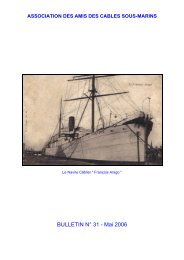
<strong>cable</strong>-ship " Frangois-Arago," for the Societie Frangaise des<br />
T61egraphes Sousmarins. The <strong>cable</strong>-ship, originally the s.s.<br />
" Westmeath," was used by the above Company in their earlier<br />
expeditions when <strong>laying</strong> the <strong>cable</strong>s connecting Brazil <strong>and</strong><br />
Guiana with the Antilles, in 1890 to 1891, for which over 300<br />
soundings were taken, <strong>and</strong> the Marseilles-Oran <strong>cable</strong> in 1892.<br />
Other types of well-known sounding tubes <strong>and</strong> detaching<br />
gear, such as the Sigsbee-Belknap, the Baillie, Hydra <strong>and</strong><br />
Brooke forms, are fully described in an able Paper read<br />
before the Society of Telegraph-Engineers <strong>and</strong> Electricians in<br />
November, 1887, on "Deep-Sea Sounding in Connection with<br />
Telegraphy," by Edward Stallibrass, F.R.G.S. {Journal of the<br />
Society, Vol. XVI., page 479). This Paper deals exhaustively<br />
with the apparatus in use, giving also the results of long<br />
experience in the work, <strong>and</strong> should be referred to for a further<br />
Btudy of the subject.<br />
For running out <strong>and</strong> recovering the line a sounding machine<br />
is fitted at the stern of the ship. One of the earliest machines<br />
was that used by the Silvertown Company for many years <strong>and</strong><br />
illustrated in Figs. 6 <strong>and</strong> 7. The drum containing the sound<br />
ing wire was moved into the overhanging position, as in Fig. 6<br />
to lower the tubes <strong>and</strong> sinker, the wire then being unwound<br />
straight from the drum <strong>and</strong> falling clear of the ship. For<br />
reeling-in, the drum was put back to the position in Fig. 7,<br />
<strong>and</strong> the wire led over to swivel pulley C, round the auxiliary<br />
pulley B, <strong>and</strong> up to the drum. In these particulars the<br />
machine did not differ from that first used by Lord Kelvin^
SURVEYING THE ROUTE. \f<br />
<strong>and</strong> described by him in the Paper before the Society of<br />
Telegraph Engineers already referred to. The auxiliary pulley<br />
B is that to which power was applied for winding in the wire.<br />
In Lord Kelvin's machine this was done by h<strong>and</strong>, <strong>and</strong> at times<br />
by an endless rope <strong>and</strong> donkey engine, while in the Silvertown<br />
type a small steam engine was geared to this pulley for the<br />
purpose. In the original machine a form of brake was applied<br />
to the drum, varied by weights suspended from the brake-strap.<br />
On starting to lower with a 341b. sinker the weights on the<br />
Fig, 6.—Taking a Sounding.<br />
brake were adjusted to give a counter pull of about 101b.,<br />
leaving the balance of 241b. to cause descent. This effective<br />
weight was maintained during the whole of the descent by<br />
adding weights at intervals to counterbalance the weight of<br />
wire out. The weight of the wire being 121b. per 1,000<br />
fathoms, a weight on the brake equivalent to 31b. pull on the<br />
wire was added every 250 fathoms out.<br />
The object of this adjustment was that when the sinker<br />
touched bottom (thus removing 341b. ofi the wire) there wa
10 SUBMARINE CABLE LAYING AND REPAIRING,<br />
left a back pull of 101b., tending to stop the wire paying out<br />
further. The mean speed of descent was only about 65 fathoms<br />
per minute.<br />
The drum was made very light, of thin sheet galvanised<br />
iron, to give it small inertia <strong>and</strong> prevent its shooting the wire<br />
forward when the weight touched bottom. The auxiliary<br />
pulley B for reeling-in was driven through speed-reducing gear<br />
by the pinion A connected to the steam engine, <strong>and</strong> the wire<br />
drum was driven by a b<strong>and</strong> from B, a lever <strong>and</strong> tightening<br />
gear being attached. The pulley C turned in any direction on<br />
a centre coinciding with the horizontal portion of the wire, <strong>and</strong><br />
Wire Drum in position<br />
for hauling in.<br />
Fig. 7.—Silvertown Sounding Machine.<br />
was therefore free to take up a position agreeing with any<br />
direction in which the wire might stream out from the ship.<br />
As the wire came up it was dried by passing through a block<br />
of indiarubber <strong>and</strong> oiled by passing through a brush saturated<br />
with lard oil, thus keeping it in good condition.<br />
This machine is now superseded by machines adapted for the<br />
use of heavier sinkers <strong>and</strong> greater speeds of descent. As the<br />
moment of striking bottom can now be easily detected when the<br />
line is run out at a speed of 100 to 150 fathoms per minute, it<br />
not of importance to have the sounding machine drum of light<br />
construction, <strong>and</strong> the system described above of adding weights
SURVEYING THE ROUTE. 11<br />
to balance the weight of wire outboard has long since been<br />
discarded.<br />
The Lucas h<strong>and</strong> sounding machine is illustrated in Figs. 8<br />
<strong>and</strong> 9. This machine is used principally for depths up to<br />
400 fathoms <strong>and</strong> for flying soundings. The chief point in the<br />
design is the automatic application of a brake to the wire<br />
drum immediately the sinker strikes bottom. The drum is<br />
thus prevented from overrunning <strong>and</strong> shooting the wire out,<br />
forming coils <strong>and</strong> kinks in it. The wire runs out freely while<br />
the weight is sinking (the brake being slack), but the moment<br />
l)ottom is reached the motion of the drum is arrested. The<br />
wire is contained on the drum or reel A, <strong>and</strong> when in use is<br />
unwound from the underside <strong>and</strong> taken one complete turn<br />
round the wheel E. The spindle of the latter is mounted in<br />
a frame B, capable of swivelling about the hollow bearing C,<br />
through which the wire passes.<br />
The frame also carries a revolution counter gearing into a<br />
pinion on the spindle. The hollow bearing C, <strong>and</strong> with it the<br />
wheel <strong>and</strong> frame B <strong>and</strong> the upright F, are capable of moving<br />
in a vertical plane about the centre D, taking up the position<br />
shown in full lines when the wire <strong>and</strong> weight are running<br />
out.<br />
In this position the bar J is moved to the left, <strong>and</strong> the brake<br />
b<strong>and</strong> I round the reel slackened, allowing the wire to run<br />
out freely. Immediately the tension on the wire is relieved by<br />
the weight touching bottom the spring G pulls the parts<br />
F, B <strong>and</strong> C into the position shown by the dotted lines, causing<br />
the bar J to be pulled to the right <strong>and</strong> the brake to be<br />
instantly applied.<br />
The lever K moves with F, C <strong>and</strong> B about the centre D, <strong>and</strong><br />
the pawl which it carries can be engaged in the teeth of the<br />
rack to lock the above movable parts in any position. Thus,<br />
when putting sinker on to end of line previous to running<br />
out, it is convenient to have the brake applied to the machine,<br />
which is done by locking the lever K in the position shown by<br />
dotted lines. In this machine, which is not used for great<br />
depths, the wire is reeled in by h<strong>and</strong>,<br />
A modified form of the apparatus is shown in Fig, 9.<br />
The wire passes from the large reel, <strong>and</strong> makes one turn<br />
round the suspended wheel, which also carries the indicator
12 SUBMABINE CABLE LAYING AND REPAIRING.<br />
Fig. 8.—Lucas Sounding Machine.<br />
Fig. 9.—Lucas Sounding Machit3e for 400 Fathoms.
SURVEYING THE ROUTE. 13<br />
showing number of fathoms. The curved arm carrying this<br />
wheel moves in a vertical plane similarly to the lever F in the<br />
type last described. There are two horizontal springs tending<br />
to pull this arm inwards, <strong>and</strong> apply the brake to the wire<br />
reel. While the wire with sinker <strong>and</strong> tube is running out over<br />
the small wheel the weight keeps the wheel <strong>and</strong> arm down, in<br />
which position the brake b<strong>and</strong> is slack, but immediately the<br />
weight is taken off by the sinker touching bottom, the springs<br />
pull up the wheel <strong>and</strong> arm, thus applying the brake in the<br />
manner described, <strong>and</strong> stopping the reel. When used for<br />
taking flying soundings—that is those taken while the ship<br />
is under way (generally at about half-speed)—a correction<br />
has to be applied for the lead of the wire, but this is some-<br />
times avoided by the simultaneous use of pressure tubes<br />
or gauges, which indicate the depth by the sea pressure.<br />
Lock Screw. H<strong>and</strong> Wheel for Setting Brake Spring.<br />
r.^s^
14 SUBMAEINE CABLE LAYING AND REPAIRING.<br />
In these engines, "with trunk guides <strong>and</strong> rods working on one<br />
crank-pin brass, an inch or two clearance may be allowed<br />
between the brass <strong>and</strong> crank webs, so giving enough end-play<br />
to shift the shaft <strong>and</strong> pinion in or out of gear. In this case,<br />
the end-play is controlled by the vertical lever at the back<br />
(Fig. 10), working inacollar on the shaft <strong>and</strong> fitted with quadrant<br />
<strong>and</strong> lock screw. In the illustration the pinion is in gear ; by<br />
setting the lever back, the pinion is taken out of gear. The<br />
bed carrying the sounding machine <strong>and</strong> engine is mounted on<br />
a stout wood frame fixed to the aft rails at one end <strong>and</strong> to a<br />
rigid support at the other (Fig. 11). The illustrations show<br />
Fig. 11.— Mounting of Sounding Gear on Aft Rails.<br />
the machine in the position for taking soundings with the<br />
measuring wheel overhanging the ship's rail. The apparatus<br />
is, however, very seldom used in the overhanging position as it<br />
is far better when paying out to place it inboard so that there<br />
is a fair length of wire between it <strong>and</strong> the ship's stern. In the<br />
arrangement shown in the illustrations provision is made for<br />
fixing the sounding gear in either of these positions—inboard<br />
or overhanging the rail. For this purpose the platform is<br />
made sufficiently long to permit of the sounding gear <strong>and</strong><br />
engine being shifted further back from the position in the<br />
illustration. The frame is provided with guides on each side,
SURVEYING THE EOUTE. 15<br />
<strong>and</strong> fresh holding down bolt holes for use when the apparatus<br />
is in the inboard position.<br />
As the steam <strong>and</strong> exhaust pipes must be disconnected when-<br />
the apparatus is to be withdrawn, short bends are provided on<br />
these pipes next the engine, which can be uncoupled, leaving<br />
the apparatus free for moving. These short bends are seen in<br />
the illustration (Fig. 11). For reeling in the wire the gear<br />
may be put back to the overhanging position <strong>and</strong> the steam<br />
<strong>and</strong> exhaust bends coupled up, or special templet bends suitable for<br />
connection to the engine in the inboard position may be provided.<br />
In this machine the tension of the spring G (Fig. 8) for<br />
setting up the brake can be increased for greater depths by<br />
means of the h<strong>and</strong> wheel seen at the top of the machine <strong>and</strong><br />
locked in any required position by a h<strong>and</strong> lock screw. A scal&<br />
of depths is fixed to indicate the proper position of the tension<br />
screw for various depths. There is also the useful adjustment<br />
of a right <strong>and</strong> left h<strong>and</strong>ed screw for shortening or lengthening<br />
the rod attached to brake strap.<br />
Another form of sounding machine which has been very<br />
successful in deep sea work is that designed <strong>and</strong> manufactured<br />
by Messrs. Johnson <strong>and</strong> Phillips, of London. This machine,<br />
as will be seen by the illustration (Fig. 12), is fitted with a<br />
small steam engine for reeling in the sounding wire. There<br />
are three shafts—viz., that of the engine, wire drum, <strong>and</strong><br />
measuring wheel—<strong>and</strong> these are connected by two endless ropes<br />
<strong>and</strong> sets of speed-reducing pulleys. The engine drives the<br />
measuring wheel shaft by one b<strong>and</strong> <strong>and</strong> this shaft drives th&<br />
drum through the other. As will be seen, there are two<br />
pulleys, adjustable in a vertical direction, for tightening the<br />
ropes. The pulleys on the drum <strong>and</strong> measuring wheel shafts<br />
bear the same ratio of diameters as those of the wheel <strong>and</strong><br />
drum, so that the two latter are driven at the same circum-<br />
ferential speed. It is recommended to mount the machine on<br />
a spring bar supported on the ship's rail, <strong>and</strong> carrying also a<br />
leading wheel. Springs attached to the inboard end of the<br />
bar to be secured to an eye on deck, allowing the bar to<br />
compensate for the motion of the ship. When the engine<br />
is not required, as in paying out, the rope pulleys must be<br />
thrown out of gear by the clutches G G. The wire is then led<br />
from the drum <strong>and</strong> two or three turns taken round the
16 SUBMARINE CABLE LAYING AND RPPAIBING.<br />
measuring wheel (which is exactly 3 feet in circumference) <strong>and</strong><br />
then over the lead wheel. The sinker is then attached with a<br />
Fig. 12.—Johnson <strong>and</strong> Phillips' Steam Sounding Machine.<br />
suitable line <strong>and</strong> lowered to the level of the water, the h<strong>and</strong>s<br />
of the indicator M being set at zero.
, fingers<br />
SURVEYING THE ROUTE. 17<br />
It is recommended that the friction brake should be adjusted<br />
io almost counteract the weight of the sinker. The moment of<br />
striking bottom can be detected by the h<strong>and</strong> placed on the<br />
spring bar.<br />
The strain in winding in must be taken by the measuring<br />
wheel. Should the wire be wound on the drum under the<br />
strain it would probably collapse ; the wire between the<br />
measuring wheel <strong>and</strong> the drum should be felt, <strong>and</strong> if too tight<br />
the rope must be loosened by lowering the pulley P.<br />
The wire should be passed through a greasy cloth as it is<br />
being guided on to the drum to wipe off the moisture.<br />
H<strong>and</strong>les are supplied which fit on the square ends of the<br />
shafts, so that the machine may be worked by h<strong>and</strong> should<br />
steam at any time not be available. After a sounding has been<br />
taken the drum with the wire should be taken oflf <strong>and</strong> kept in<br />
the oil tank until again required.<br />
With this apparatus the <strong>cable</strong> ship "Amber" took 380<br />
soundings between Bonny, in the G-ulf of Guinea, <strong>and</strong> the<br />
Cape, only losing 1 per cent, of sounding wire out of a total<br />
length run out of over 212 thous<strong>and</strong> fathoms. These sound-<br />
ings were taken over a zigzag course of about 3,400 miles, the<br />
direct distance being about 2,700 miles, corresponding to one<br />
sounding every 7 miles.<br />
A simple automatic attachment to a sinker for bringing up<br />
specimens of bottoui has been devised by Mr. F. R. Lucas,<br />
of the Telegraph Construction <strong>and</strong> Maintenance Co. (Fig. 13.)<br />
The cup-shaped jaws are kept apart during descent by two<br />
mounted on spindles, whose bearings are in the side of<br />
the gunmetal cups. The brass stem supporting the jaws<br />
screws into a bush in the interior of the lead sinker, as shown,<br />
<strong>and</strong> a stout spiral spring bears down on the top of the jaws.<br />
To set for lowering, the cups are opened <strong>and</strong> the two small<br />
fingers inside placed horizontally so that the pointed end of one<br />
engages in the recessed end of the other (while doing this one<br />
looks after one's own fingers). This maintains the cups apart,<br />
as in the illustration, during descent ;<br />
bat on striking bottom<br />
the force of impact, if on a hard substance, suffices to disengage<br />
the fingers, <strong>and</strong> the cups are brought smartly together by the<br />
apring above them, thus cutting into <strong>and</strong> securing a sample of<br />
the sea bed. It is found to be verv certain in action in all
18 SUBMARINE CABLE LAYING AND REPAIEING.<br />
bottoms except soft ooze, in which it sinks without impact.<br />
Whenever the jaws come up unclosed after touching bottom, it<br />
is a sure sign that the bottom is soft mud. In this particular<br />
design the sinker is heaved up with the sounding wire.<br />
On the occasion of the " Challenger " Expedition Mr. J. Y.<br />
Buchanan devised instruments (for use in conjunction with<br />
the sounding line) which indicated the depth by the barometric<br />
method <strong>and</strong> gave very concordant results. These instruments<br />
Fig. 13.—Lucas's Snapper, for bringing up Specimens of Sea Bottom.<br />
were described by him in a lecture before the Chemical<br />
Society in 1878, entitled "Laboratory Experiences on board the<br />
' Challenger'" {Journal of the Chemical Society, October, 1878),<br />
<strong>and</strong> are known as the water <strong>and</strong> mercury piezometers (Fig. 14).<br />
This method was adopted for the reason that the sounding line<br />
is sometimes affected by deep-water currents, which cause<br />
errors in the measurement of depth. Generally the effect of<br />
these currents is noticed by the streaming out of the line,<br />
<strong>and</strong> the ship has to be manoeuvred to follow it <strong>and</strong> endeavour
SURVEYING THE ROUTE. 19<br />
to keep it vertical. At other times there may be currents in<br />
various directions <strong>and</strong> at various depths which show no effect<br />
on the line at the surface, but cause more than the true length<br />
£^j^^&^ jM<br />
Fig. 14.—Buchanan's Water <strong>and</strong> Mercury Piezometers<br />
of sounding line for the depth to be paid out. The piezometers<br />
enabled the indications of the sounding line to be verified <strong>and</strong><br />
corrected when necessary.<br />
For the most exact determinations the two instruments are<br />
c2
20 SUBMARINE CABLE LAYING AND REPAIBING.<br />
used together, <strong>and</strong> the true bottom temperature aa well as the<br />
true depth are thereby obtained. From the illustrations of<br />
these instruments (kindly lent the author by the manufacturer,<br />
Mr. Louis P. Casella) it will be seen that both are of the same<br />
construction, except that the mercury piezometer has a bent<br />
tube to prevent the mercury flowing down the stem. The<br />
stem of each instrument dips into a bulb partially filled with<br />
mercury <strong>and</strong> is rather a loose fit in the neck of the bulb. A<br />
wide rubber b<strong>and</strong> is used to bind the bulb <strong>and</strong> stem together,<br />
but in order that water may gain access to the mercury in the<br />
bulb (to exert its pressure in the same way as air upon the<br />
mercury in an ordinary barometer), a glass pin is pushed in<br />
the b<strong>and</strong> between the stem <strong>and</strong> the bulb, as shown in the<br />
figures. The apertures left on either side of the pin sufl&ce<br />
for allowing the pressure to act, but are so small that it is<br />
practically impossible for the mercury to escape. In the water<br />
piezometer the cylindrical bulb at the top, <strong>and</strong> the stem, are<br />
nearly filled with distilled water, the junction between the<br />
water <strong>and</strong> mercury in the stem being arranged at a convenient<br />
height at ordinary temperature. At the junction of the two<br />
liquids there is a magnetic index, as in Six's thermometer, held<br />
in the tube by a small piece of human hair, acting as a spring.<br />
This registers the maximum range of pressure <strong>and</strong> temperature<br />
to which the instrument has been subjected when let down to<br />
the bottom of the sea <strong>and</strong> drawn up again on the sounding line.<br />
As the tube descends the pressure of sea-water on the<br />
mercury in the lower bulb increases at the rate of 2681b. per<br />
square inch (or about 18 -2 atmospheres) for every 100 fathoms<br />
depth. This forces up the water in the stem, <strong>and</strong> contracts it<br />
in volume. The mass of water in the upper bulb is also con-<br />
tracted by the decrease in temperature, so that the position of<br />
the index registers the sum of these two eflfects. How much<br />
of the reading is due to pressure, <strong>and</strong> how much to tem-<br />
perature, can be found by sinking a thermometer at the<br />
same time as the piezometer. Then, deducting the contraction<br />
of the piezometer column due to the temperature shown on the<br />
thermometer, we have that due to depth alone. The apparent<br />
contraction of the water (that is in the glass, the glass also<br />
being contracted in volume) per degree of temperature <strong>and</strong> per<br />
100 fathoms depth was determined by Mr. Buchanan for the
SURVEYING THE ROUTE. 21<br />
particular instruments he used. These are given in the Paper<br />
above referred to, which should be consulted for a more detailed<br />
study of the subject.<br />
Mr. Buchanan improved on this method by the simultaneous<br />
use of a mercury piezometer. In this instrument the upper<br />
bulb is filled with mercury rising a portion of the way in the<br />
tube. The bent portion of the tube <strong>and</strong> the downward leg<br />
are filled with water, <strong>and</strong> the column of water rests on the<br />
short mercury column which forms part of that in the lower<br />
bulb.<br />
The action of this instrument is precisely the same, the mass<br />
of mercury being contracted by the increase of pressure <strong>and</strong><br />
decrease of temperature, <strong>and</strong> the maximum contraction at the<br />
bottom of the sea being registered. The mercury instrument<br />
is much more afi"ected by temperature than pressure, <strong>and</strong> the<br />
water instrument more by pressure than temperature. Conse-<br />
quently the reading which is liable to error in one instrument<br />
is susceptible of great accuracy in the other.<br />
Both instruments are sent down together on the sounding<br />
line. The depth indicated by the line out (considered as an<br />
approximate measurement only) is then taken <strong>and</strong> used in<br />
clearing the reading on the mercury piezometer for pressure,<br />
leaving an exceedingly close first approximation to the tempera-<br />
ture. This result is then used to clear the reading on the<br />
water piezometer for temperature, which then gives the true<br />
depth. And again, this result is used to clear the mercury<br />
instrument for pressure, which then gives the true temperature.<br />
In addition to the barometric method of Buchanan, a simple<br />
form of pressure gauge, in which the pressure acts through an<br />
elastic diaphragm, has been introduced by Messrs. Bucknill<br />
<strong>and</strong> Casella. The instrument is enclosed in a strong water-<br />
tight case <strong>and</strong> lowered in the ordinary way on the sounding<br />
line about six feet above the lead sinker. The index on the<br />
dial records the maximum depth in fathoms. The advantage<br />
of instruments of this class is that under-currents do not cause<br />
errors in the measurement, <strong>and</strong> there is no necessity to keep<br />
the sounding line absolutely vertical.<br />
We now come to the measurement of ocean temperatures.<br />
Thermometers for use in the sea at great depths require pro-<br />
tection against the enormous pressure to which they are
22 SUBMARINE CABLE LAYING AND REPAIRING.<br />
subjected. At 2,500 fathoms the pressure amounts to 3 tons<br />
per square inch, or about 455 atmospheres, increasing about<br />
1 atmosphere for every 5^ fathoms depth. Before protected<br />
A<br />
"^^<br />
Dl<br />
SI<br />
gz<br />
08<br />
SB<br />
»<br />
Supporting<br />
Piece.<br />
Indiarubber<br />
Pacl
SURVEYING THE ROUTE. 23<br />
the bulb. Referring to Fig- 15 it will be seen that the<br />
mercury column has a peculiar bend a little above the bulb.<br />
It is curved <strong>and</strong> narrowed down at A, widened into a small<br />
chamber at B, <strong>and</strong> curved again. At ordinary temperatures<br />
the mercury column is somewhat above this chamber, the<br />
thermometer st<strong>and</strong>ing vertically with the bulb downwards, as<br />
in the figure. In this position at high temperatures the<br />
mercury may rise <strong>and</strong> partially fill the reservoir C. When it is<br />
desired to register the temperature at any particular place the<br />
thermometer is turned upside down. The mercury in the<br />
column above the contracted portion A then falls to the other<br />
end of the stem, <strong>and</strong> so long as the instrument is kept in an<br />
inverted position no more mercury can fall through, thus<br />
keeping a correct record of the temperature at that particular<br />
spot. Should the instrument be subsequently subjected to a<br />
higher temperature than that registered, the mercury can<br />
exp<strong>and</strong> into the chamber B <strong>and</strong> lodge there without afiecting<br />
the indication. The higher temperature would, however, aflfect<br />
the separate portion somewhat, but not to any great extent<br />
on account of the small mass of mercury. The column is a<br />
thin flat one, not circular in section. For strict accuracy,<br />
however, there should be a correction table for applying to the<br />
readings to eliminate the eflfect of the temperature at which the<br />
instrument is read. The scale of degrees is inverted as the<br />
temperature recorded is read with the instrument upside<br />
down.<br />
The thermometer is enclosed in a glass protecting tube as<br />
shown in Fig. 15. There is an air-tight cemented rubber<br />
partition fixed at D below which mercury is filled in to a<br />
certain height, the remaining space being exhausted of air.<br />
This is done by filling the whole of the space with hot mercury,<br />
which when cooled down leaves a vacuum. The mercury<br />
jacket round the thermometer bulb forms a heat-conducting<br />
medium which renders the protected bulb very sensitive to<br />
external changes of temperature. Under deep-sea pressures<br />
the outside tube is compressed, <strong>and</strong> the space within the<br />
jacket correspondingly diminished, but as the jacket is<br />
partially exhausted of air this compression is not transmitted<br />
to the thermometer bulb, <strong>and</strong> therefore the instrument itself is<br />
protected, <strong>and</strong> its indications freed from any error due to
24 SUBMARINE CABLE LAYING AND REPAIRING.<br />
pressure. It is usual to make these instruments to st<strong>and</strong><br />
testing in an hydraulic press to pressures varying from 2^ to<br />
5 tons per square inch according to the depth for which they<br />
are required.<br />
There are several methods of capsizing the instrument at<br />
any required depth in the sea. One is that suggested to the<br />
makers by Comm<strong>and</strong>er Magnaghi, of the Royal Italian Navy.<br />
This arrangement is shown in Fig. 16. The brass case T<br />
containing the protected thermometer is held in the frame<br />
by a screw at the top <strong>and</strong> supported on an axis H below.<br />
The screw is part of the spindle of a small propeller or fan, F.<br />
In descending, the fan is prevented from turning by the pin P<br />
touching the stop E, the latter being capable of adjustment to<br />
regulate the distance the screw enters the case. On ascending,<br />
the fan revolves in a direction causing the screw to run out of<br />
the case T : the instrument then falls over about the axis<br />
H <strong>and</strong> registers the temperature at that spot. The tube in<br />
this position is locked by the spring pin <strong>and</strong> cam at S. These<br />
instruments are attached to the sounding line as shown, <strong>and</strong><br />
at different depths on the same line when serial temperatures<br />
are required, the lowest thermometer being at a few feet above<br />
the sounding tubes <strong>and</strong> sinker.<br />
The action of the rotating fan is not perfectly reliable : it<br />
sometimes happens that the instrument reverses coo late or<br />
too early. To obviate this, Messrs. Negretti <strong>and</strong> Zambra<br />
devised a capsizing arrangement acting by means of a weight<br />
let down the sounding line (Fig. 17). The weight hits against<br />
the lever, L, which raises the spindle S <strong>and</strong> releases the<br />
thermometer case T. This is pivoted on the axis H (but not<br />
balanced) <strong>and</strong> as soon as released at the top it turns upside<br />
down, at the same moment freeing the weight W, which falls<br />
down the line <strong>and</strong> capsizes the next thermometer in a similar<br />
manner. This releasing arrangement has been found very<br />
certain in action.<br />
Another capsizing device by the same makers is very suitable<br />
for temperature sounding in shallow water. The thermometer<br />
is mounted on a hollow wooden frame loaded with shot, free to<br />
move from end to end of the frame, <strong>and</strong> sufi&cient to render<br />
the whole instrument just vertically buoyant in sea water.<br />
The cord attaching the instrument to the sounding line is
SURVEYING THE ROUTE. 25<br />
fixed at the bulb end of the frame, so that, in descending, the<br />
bulb is kept downwards. On starting to haul up, the resis-<br />
tance of the water causes the frame to turn ; the shot then<br />
takes the other end of the frame, the bulb comes uppermost,<br />
<strong>and</strong> the temperature is registered as before.<br />
The Buchanan-Miller-Casella self-registering deep-sea thermometer<br />
is the latest development of Six's original instrument.<br />
Referring to the illustration (Fig. 18), this thermometer con-<br />
H[<br />
/ Screw<br />
Fig. 16.<br />
Fan Capsizing Frame<br />
(Magnagni).<br />
Fig. 17.<br />
Weight Capsizing Frame<br />
(Negretti <strong>and</strong> Zambra).<br />
sists of a U tube with two upper bulbs. That on the left is<br />
the one directly affected by the temperature, <strong>and</strong> is filled with<br />
spirit in the bulb <strong>and</strong> partly down the stem. This bulb is<br />
protected against pressure by being enclosed in another bulb<br />
partly filled with spirit, a bubble of vapour being left to<br />
allow for compression of the space when subjected to<br />
pressure. The smaller bulb <strong>and</strong> a portion of the tube on
26 SUBMARINE CABLE LAYING AND REPAIRING.<br />
the right have compressed air in them. Mercury is filled in<br />
the bent portion of the tube <strong>and</strong> rises a certain height in each<br />
stem. As the temperature rises the spirit exp<strong>and</strong>s, forcing<br />
down the left column of mercury <strong>and</strong> raising the right-h<strong>and</strong><br />
40-<br />
50=<br />
60:<br />
SO:<br />
90-<br />
FiG. 18.<br />
Buchauan-Miller-Casella<br />
Deep-Sea Thermometer.<br />
Fig. 19.<br />
Miller-Casella Thermometer<br />
in Case.<br />
column against the compressed air ; <strong>and</strong> on the temperature<br />
falling the spirit contracts, <strong>and</strong> the mercury in the left-h<strong>and</strong><br />
column rises <strong>and</strong> follows up the contraction by the force of
SURVEYING THE ROUTE. 27<br />
the compressed air in the other column. In each Column is<br />
an index registering the highest point reached by the mercury,<br />
that on the lefc showing the maximum cold <strong>and</strong> that on the<br />
right the maximum heat to which the instrument has been<br />
exposed. In addition to the usual scale of degrees Mr.<br />
Buchanan had a scale of millimetres engraved on the stem.<br />
This affords greater ease <strong>and</strong> accuracy of reading on account<br />
of the millimetre divisions being smaller than those of degrees,<br />
while the reading is independent of the degree scale, which<br />
may be knocked out of position relatively to the thermometer<br />
stem. When constructed, the instrument is calibrated in the<br />
usual way by immersion in water at different temperatures,<br />
say, for instance, at SOdeg., 45deg., 60deg. <strong>and</strong> 75deg., <strong>and</strong><br />
these points are etched on the glass stem. A table is then<br />
compiled showing the exact relation between millimetres <strong>and</strong><br />
degrees. Thus, if SOdeg. corresponded to 87mm., <strong>and</strong> 45deg.<br />
to 120mm., every degree would be equivalent to<br />
120-87<br />
= 2o.o •2mm.<br />
45-30<br />
As regards ordinary errors in reading, therefore (such as read-<br />
ing 52 for 57, for instance), one scale affords a good means of<br />
oheck on the other, but the millimetre scale would of course<br />
be the most correct. Supposing, for instance, the reading is<br />
33deg. <strong>and</strong> 74mm. : on referring to a table it is found that<br />
74mm. is equal, say, to 33 6deg., which is therefore the correct<br />
temperature. One disadvantage in this instrument is that the<br />
indices may get out of place, or bubbles of spirit may get into<br />
the mercury column if the line receives a jerk ; but in careful<br />
h<strong>and</strong>s it is a very reliable instrument for deep-sea work.<br />
Should the instrument encounter on its way down or up an<br />
intermediate stratum of water colder than that at the bottom,<br />
the reading would not give the correct bottom temperature<br />
but this is an exceedingly unusual occurrence, <strong>and</strong> the exis-<br />
tence of a colder belt can soon be ascertained by a few serial<br />
soundings. For lowering in the sea the thermometer is<br />
enclosed in a case, as in Fig. 19.<br />
The subject of thermometers for deep sea work was ably<br />
treated in a Paper read by the late Mr. William Lant Carpenter,<br />
B.A., B.Sc, before the Society of Telegraph Engineers <strong>and</strong>
28 SUBMARINE CABLE LAYING AND REPAIRING.<br />
Electricians, on November 8th, 1888, entitled "On Ocean<br />
Temperatures in Kelation to <strong>Submarine</strong> Cables." Mr. Car-<br />
penter's Paper, which, owing to the special <strong>and</strong> prolonged<br />
study he had devoted to the subject, was of particular interest<br />
was also the means of bringing to light considerable experience<br />
in the use of these instruments during the discussion which<br />
followed {Journal of the Society, Vol. XVII., page 658).<br />
Temperatures at the bottom of all the great oceans closely<br />
approach freezing point, the Atlantic at 2,000 fathoms depth<br />
being 36°F., <strong>and</strong> the Pacific a degree or two lower. The<br />
Mediterranean Sea is in this respect an exception, on account<br />
of its comparatively shallow connection with the Atlantic<br />
through the Straits of Gibraltar, thus preventing circulation.<br />
The temperature even at the greatest depths in this sea iS'<br />
never below 55°F.<br />
The condition of low temperature is most favourable for<br />
submarine <strong>cable</strong>s. The conductivity of the copper conductor<br />
<strong>and</strong> the resistance of the insulator are both thereby increased.<br />
The great pressure of sea water on the ocean bed also increases<br />
the insulation resistance, most remarkably so in the case of<br />
gutta-percha. On this head, information obtained at the time<br />
of <strong>laying</strong> a <strong>cable</strong> is most valuable in subsequent repair work in<br />
the same waters. After submersion the contractors carry out<br />
daily tests of the <strong>cable</strong> for one month, <strong>and</strong> amongst other<br />
determinations they measure very carefully the resistance of<br />
the conductor, making all corrections for temperature of testing<br />
room. On comparing this with the resistance of the <strong>cable</strong> as<br />
measured at the st<strong>and</strong>ard temperature of 75°F. in tank at the<br />
factory, the mean temperature of the sea in which the <strong>cable</strong> is<br />
laid is arrived at.<br />
While the observations for depth, temperature <strong>and</strong> nature of<br />
bottom are being taken the ship's position must be determined<br />
to as great a degree of accuracy as possible. For this purpose<br />
the log is always used, showing the distance travelled from one<br />
position to the next, but if the course of the ship is affected by<br />
currents or leeway the positions arrived at by dead-reckoning<br />
alone are not strictly accurate, as the compass only indicates<br />
the bearing of the ship's head, not her actual course, <strong>and</strong> the<br />
log the distance the ship has travelled through the water, not<br />
that over ground. When the sun permits, therefore, the ship's
SURVEYING THE ROUTE. 29<br />
position is checked by taking an altitude for longitude <strong>and</strong> the<br />
latitude at noon, giving the actual distance travelled over<br />
ground <strong>and</strong> the correct course from last position. The positions<br />
are carefully marked on the chart for future reference.<br />
Two forms of patent logs (Massey's <strong>and</strong> Walker's) are shown<br />
in Figs. 20 <strong>and</strong> 21 from illustrations kindly supplied by Mr.<br />
Louis Casella, of Holborn. The fans or propellers rotate at<br />
a speed proportional to the rate they are towed by the ship<br />
through the water, the tow line communicating<br />
the rotation to the indicator on<br />
board (Fig. 22), which shows the number<br />
Fig. 20.<br />
Massey's Propeller Log<br />
of knots in any period from the time of<br />
setting the apparatus. A flywheel is<br />
placed in the tow line which acts as a<br />
governor <strong>and</strong> steadies the revolutions of<br />
the indicator spindle. The indicator is<br />
made to strike a bell as each knot is<br />
recorded. Massey's propeller log (Fig. 20)<br />
registers on the log itself. The tube A A<br />
(coned at both ends for the purpose of<br />
giving a smooth action <strong>and</strong> preventing<br />
jumping from the water at high speeds)<br />
contains the register, <strong>and</strong> revolves with it<br />
on a fixed axis passing through the cone<br />
points. The axis is geared with the train<br />
of wheels of the rotating register through<br />
an endless screw, thus recording the<br />
distance run on the dial-plate C. A<br />
milled head is provided at D for turning<br />
a sleeve by which the dial-plate can be<br />
covered when in use. The towing line<br />
is attached at the thimble F, <strong>and</strong> should<br />
be long enough to allow the log to fall sufficiently astern to<br />
clear the eddy of the wake.<br />
One disadvantage of these logs is that they sink at slow<br />
speeds <strong>and</strong> do not register, <strong>and</strong> it is not practi<strong>cable</strong> to apply<br />
any floating appliance, as this would need adjustment according<br />
to speed, <strong>and</strong> the log is too far astern for any such apparatus<br />
to be controlled from the ship. A modified form of log<br />
registering from the tail, <strong>and</strong> an improved method of
30 SUBMABINE CABLE LAYING AND REPAIRING.<br />
suspending the same from the ship, by means of which it\registera<br />
at slow speeds, has been introduced by Captain Thomson, E-N.R.<br />
The general arrangement, which was described in the Paper by<br />
Mr. E. Stallibrass on " Deep Sea Sounding," already referred to,<br />
is illustrated in Fig. 23. The position of the rotator or fan as<br />
towed is at the side of the ship almost abreast of the bridge,<br />
o<br />
^
SURVEYING THE ROUTE. 31<br />
the tow line being attached to a spar (S) outrigged at the fore<br />
part of the ship <strong>and</strong> projecting about 20 feet over the side.<br />
The torsion line (t) connected to the tail of the log communi-<br />
cates the rotation to the indicator on the bridge. This position<br />
Fig. 22.—TrafFrail Indicator <strong>and</strong> Governor.<br />
is an extremely h<strong>and</strong>y one, all readings being taken on the<br />
bridge instead of calling the quartermaster <strong>and</strong> sending him<br />
aft to read the indicator. Further, the rotator is in full view.<br />
Fig. 23.—Captain Thomson's Log.<br />
<strong>and</strong> if not working properly from any cause is at once seen<br />
<strong>and</strong> put right.<br />
The depth of the log in the water is regulated by means of<br />
a chain <strong>and</strong> bearing line. The short length of chain inserted
32 SUBMAEINE CABLE LAYING AND REPAIRING.<br />
in the tow line in front of the rotator keeps it sufficiently<br />
beneath the surface when going at full speed. The bearing line<br />
is used for lifting the chain <strong>and</strong> preventing the rotator sinking<br />
when the ship slows down. This line is rove through an eye<br />
on the end of a light spar lashed to the bridge <strong>and</strong> is suspended<br />
from a high point on the foremast. The portion (C) attached<br />
directly to the chain in the water is of copper wire, which cuts<br />
the water more readily than line <strong>and</strong> affords a little extra<br />
steadiment by its weight. When the ship is rolling heavily<br />
the bearing line is slackened so as not to lift the log out of the<br />
water. This manner of supporting the log prevents it sinking<br />
when the ship slows down, <strong>and</strong>, being kept always in a hori-<br />
zontal position, the log registers correctly at quite slow speeds.<br />
This is a great improvement over a log towed from the stern<br />
which sinks as soon as the ship slows down <strong>and</strong> must be hauled<br />
in. The advantage is greatly appreciated in short distance<br />
soundings as the log always remains out <strong>and</strong> is ready for work<br />
whether the ship slows down, stops, or is manoeuvred about.<br />
In Mr. Anthony S. Thomson's Paper, before the G-eographical<br />
Congress of 1895, on "Remarks on Ocean Currents," &c., occurs<br />
the following paragraph relative to all logs, which is worth<br />
giving in full :<br />
" Whatever be the kind of patent log used, its<br />
indications should be carefully checked from time to time by<br />
comparing them with the 'Dutchman's log' at different speeds<br />
whenever any current observations are to be made. Empty<br />
bottles answer admirably for this purpose when ballasted with<br />
a little water. The observer, who st<strong>and</strong>s on the bridge with a<br />
stop-watch, requires three assistants, one to throw the bottle<br />
ahead of the ship, one to dip a h<strong>and</strong>-flag as the bottle passes<br />
his marks at the stem, <strong>and</strong> another to do the same thing when<br />
the bottle passes his marks at the stern. It is convenient to<br />
read the revolution indicator <strong>and</strong> the bridge log before <strong>and</strong><br />
after timing the bottle, with an interval of six minutes between<br />
the two sets of readings. When a number of such observations<br />
are carried out with care, the mean results will give the ship's<br />
speed through the water very accurately, <strong>and</strong> the percentage<br />
of error of the log at the given speed is easily ascertained <strong>and</strong><br />
allowed for."<br />
It is very important as regards the life of a <strong>cable</strong> that it<br />
should not be laid over a bank or steep submarine peak. Such
SURVEYING THE ROUTE. 33<br />
peaks or banks, the result chiefly of volcanic action, <strong>and</strong> of<br />
comparatively small area, are not easily found by the ordinary<br />
method of sounding at positions a few miles apart. When it ig<br />
possible to have a vessel sounding ahead of the <strong>cable</strong> steamer<br />
during the <strong>laying</strong> of a <strong>cable</strong>, the chances are that banks will be<br />
detected in time to alter the course, but while this was fre<br />
quently done in the early days of <strong>cable</strong> <strong>laying</strong>, when such<br />
enterprises received the assistance of the Government, the<br />
practice fell into disuse as the art became better understood.<br />
To take the place of this a system of sounding is organised on<br />
the <strong>cable</strong> ship while <strong>cable</strong> is being laid, <strong>and</strong> for this purpose it<br />
is not necessary to find the actual depth, but to ascertain if<br />
any rise in the ocean bed of importance occurs along the route.<br />
Various forms of sounding apparatus, appli<strong>cable</strong> while the<br />
ship is in motion, are used for this purpose. Prof. Lambert, M. A.,<br />
of the Eoyal Naval College, Greenwich, enumerated the most<br />
important of these in his interesting lecture at the Eoyal<br />
United Service Institution on June 3rd, 1891, entitled<br />
"Sounding Machines for the Prevention of Str<strong>and</strong>ings, with<br />
Special Reference to James' <strong>Submarine</strong> Sentry." Reprints of<br />
this lecture, to which the reader is referred, can be obtained at<br />
the office of the <strong>Submarine</strong> Sentry, 18, Billiter-street, London,<br />
E.G. First <strong>and</strong> foremost comes the compressed air depth gauge<br />
<strong>and</strong> depth recorder of Lord Kelvin, the former instruments<br />
being usually known as "Thomson's Tubes." A thin glass<br />
tube about 2ft. long, open only at the bottom, is let down<br />
enclosed in a brass case with sinker. Water rises in the tube<br />
proportionally to the depth <strong>and</strong> pressure, compressing the air<br />
within the tube, <strong>and</strong> in doing so washes away a red chemical<br />
preparation with which the inside of the tube is coated, thus<br />
leaving a record of the greatest depth to which the instrument<br />
has been lowered. After hauling in, the indication is reduced<br />
to fathoms depth by reference to a table, which also supplies<br />
the necessary correction for barometric pressure. Other forms<br />
are Cooper <strong>and</strong> Wigzell's piston type of pressure instrument<br />
Basnett's compression gauge, which retains the water column ;<br />
Burt's "Bag <strong>and</strong> Nipper"; <strong>and</strong> the <strong>Submarine</strong> Sentry,<br />
invented by Mr. Samuel James, C.E. The advantage of the<br />
latter apparatus is that it can be towed by the ship at a fixed<br />
depth within a considerable range of speed, <strong>and</strong> automatically
34 SUBMARINE CABLE LAYING AND REPAIRING.<br />
gives warning on deck when bottom, at this depth is touched.<br />
The apparatus can be set to any depth up to about 35 to 45<br />
Fig. 24.—James' <strong>Submarine</strong> Sentry.<br />
fathoms, <strong>and</strong> is very suitable for use when <strong>laying</strong> <strong>cable</strong> in com-<br />
paratively shallow water, such as those following coast lines.<br />
Fig. 25.—Sentry trailing.<br />
The "Sentry" consists of two pieces of wood joined at an angle<br />
forming a " kite " together with pin, spring <strong>and</strong> striker, as
SURVEYING THE ROUTE.<br />
shown in Fig. 24. The illustration represents the position<br />
assumed by the "kite " when towed by the ship. The pecu-<br />
liarity of its action is that it causes the tow line (of steel wire)<br />
to take up a concave downward curve, as in Fig. 25, <strong>and</strong><br />
that the form of this curve remains practically unchanged for<br />
any variation in ship's speed between 5 <strong>and</strong> 1 3 knots. Conse-<br />
FiG. 26.— Sentry overturned.<br />
quently, the apparatus stays at any fixed depth in the water<br />
(at which it is originally set), notwithst<strong>and</strong>ing that the ship<br />
may alter her speed within the above limits. The moment<br />
the lower end of the striker touches ground the upper end is<br />
forced away <strong>and</strong> releases the pin. The forward sling then<br />
slips oflf the pin, <strong>and</strong> the "kite" is towed by the hinder<br />
sling only. Under these circumstances it no longer has a<br />
Fig. 27.—Sentry Winch.<br />
" kite " action, <strong>and</strong> simply turns over <strong>and</strong> floats to the<br />
surface like any ordinary piece of wood (Fig. 26). The<br />
release of the strain on the towing wire resulting from this<br />
action causes a bell to ring, announcing to those on board that<br />
they have only so many fathoms under them. The apparatus,<br />
therefore, keeps a continuous under-water lookout <strong>and</strong> auto-<br />
d2<br />
35
36 SUBMAEINB CABLE LAYING AND REPAIRING.<br />
matically gives warning of the approach of shallow water, for<br />
which reason it has been largely adopted by the Navy <strong>and</strong><br />
Mercantile Marine as a precaution for safety.<br />
The apparatus is lowered from a fairlead (B) fixed so as to<br />
overhang clear of ship's stern, <strong>and</strong> at such a height that the<br />
wire coming from the winch assumes an angle approximately<br />
as shown in Fig. 27. The ship is slowed to 9 or 10 knots<br />
while lowering, a strain being meanwhile kept on the wire by<br />
means of a light pressure on the h<strong>and</strong>-brake lever. As the<br />
kite sinks its vertical depth from the fairlead is shown on a<br />
dial attached to the winch, <strong>and</strong> when the desired depth is<br />
reached the brake is applied sufficiently to stop paying out,<br />
<strong>and</strong> the wire drum locked by engaging a pawl in a ratchet<br />
wheel attached thereto. Single casts for depth can also be<br />
taken by the apparatus, <strong>and</strong> the depth read off the dial<br />
instantly without waiting to haul in.
CHAPTER 11.<br />
PRINCIPLES OF DESIGN AND CONSTRUCTION OF<br />
CABLES.<br />
The specification for a new <strong>cable</strong> generally exacts a guarantee<br />
for the attainment of a certain speed of signalling. If the<br />
<strong>cable</strong> is to be laid between shores already connected by other<br />
<strong>cable</strong>s, a higher rate of signalling than on any of the existing<br />
<strong>cable</strong>s is generally required. In order to calculate the weights<br />
of conductor <strong>and</strong> insulator, to ensure the required speed being<br />
attained when the <strong>cable</strong> is laid, information from the most<br />
trustworthy sources as to the depths <strong>and</strong> temperatures of the<br />
ocean along the proposed route must be at h<strong>and</strong>. If no <strong>cable</strong><br />
has been laid there before, the charts are referred to for depths.<br />
The charts, however, do not give the data on bottom tempera-<br />
tures, nor sufficient data on depths, <strong>and</strong> a margin has therefore-<br />
to be allowed in the calculations. Where <strong>cable</strong>s have been<br />
laid the mean temperature of sea bottom can be accurately<br />
calculated from measurements of the conductor resistance, <strong>and</strong><br />
the depths are fairly well known <strong>and</strong> checked during subsequent<br />
repairs. A great deal of information of this kind has thus<br />
become known which would not otherwise have been brought<br />
to light.<br />
Principles of Design.—An important factor to consider in<br />
design is what is termed the KR of the <strong>cable</strong>. This is the total<br />
capacity of the <strong>cable</strong> in microfarads (K) multiplied by the total<br />
resistance of the conductor in ohms (R). The total capacity of the<br />
dielectric is the capacity per naut in microfarads (k) multiplied by
38 SUBMARINE CABLE LAYING AND KEPAIRING.<br />
the length of the <strong>cable</strong> {I), <strong>and</strong> similarly the total resistance of<br />
the conductor is the resistance per naut in ohms (r) multiplied<br />
by the length of the <strong>cable</strong>. Therefore the KR of a <strong>cable</strong> may<br />
be expressed as M x rl, which is equal to krP. That is the<br />
product of the capacity per naut in microfarads, the resistance<br />
per naut in ohms <strong>and</strong> the square of the length in nauts. For<br />
future reference this is put in the form of the equations :<br />
KR = krP, (1)<br />
KR<br />
f^r = jr (2)<br />
The comparison of speeds of signalling must be reduced to<br />
a common basis to be of any value. It is usual now for speeds<br />
to be reckoned on the basis of "letters per minute," but it<br />
must be explained that this figure is not arrived at by counting<br />
the number of letters transmitted in one minute in any kind<br />
•of message, because the useful space taken up per letter varies<br />
in different letters, <strong>and</strong> the word spacings also vary with the<br />
length of the words used. To form some letters on the recorder<br />
instrument it takes four impulses or " contacts," while other<br />
letters take only three, two or one, <strong>and</strong> the time occupied in<br />
transmitting them is strictly in proportion to the number of contacts<br />
made in forming each letter. A message taken at r<strong>and</strong>om<br />
might be composed of words having letters of few impulses, <strong>and</strong><br />
such a message could be transmitted quicker than one composed<br />
of words having letters taking longer to form. Hence, to calcu-<br />
late the number of letters per minute on a common basis, the<br />
average number of contacts per letter must be arrived at by<br />
taking some representative traffic matter, adding all the<br />
necessary contacts together <strong>and</strong> dividing by the total number<br />
of letters. This has been carefully done on the Eastern <strong>and</strong><br />
other systems, <strong>and</strong> the result shows an average of 2*6 contacts<br />
per letter (see The Electrician, April 23, 1897). It is further<br />
necessary to allow for the spaces between letters, which is<br />
represented by one contact. The space taken by the average<br />
letter with its space is therefore represented by 3*6 contacts.<br />
Mr. E. Raymond-Barker has independently arrived at this<br />
identical figure from examination of 1,000 words of ordinary<br />
language (see Electrical Review, Vol. XL., pp. 517 <strong>and</strong> 600).<br />
The space between words is also taken account of <strong>and</strong> may be
PRINCIPLES OF DESIGN. 39<br />
reckoned on the basis of a five, eight or ten-letter word as may<br />
be agreed upon. This spacing is equivalent to two contacts,<br />
one of which belongs to the proper space after each letter<br />
(allowed for by the above figure). Tnere is, therefore, one<br />
extra contact to be allowed for spaces between words, <strong>and</strong> if<br />
the average word is considered as of five letters, the part of a<br />
contact per letter representing word spaces would be | = 0"2<br />
<strong>and</strong> the total contacts per letter 3 6 + 0*2 = 3-8. Again, if a<br />
ten-letter word is taken as a basis we have to add J;j = 0'l <strong>and</strong><br />
the contacts per letter become 3*6 + 0-1 = 3'7.<br />
In the auto-transmitter each of the centsre holes in the per-<br />
forated slip represents one contact, <strong>and</strong>, therefore, the speed in<br />
"letters per minute" on this basis can readily be observed<br />
where these instruments are in use by counting the number of<br />
centre holes per minute <strong>and</strong> dividing by the number 3 8 or 3*7<br />
for five or ten-letter words respectively.<br />
Wich st<strong>and</strong>ard conditions as to battery power, receiving <strong>and</strong><br />
sending condensers <strong>and</strong> sensitiveness of receiving instrument,<br />
the speed of signalling on all submarine <strong>cable</strong>s, of whatever<br />
size, type or length, varies In inverse proportion to the respective<br />
KR of each.<br />
Take, for Instance, two <strong>cable</strong>s, one of 1,500 nauts, with<br />
a conductor resistance of 6 ohms per naut <strong>and</strong> capacity of<br />
0-35 microfarad per naut, <strong>and</strong> the other of 2,000 nauts with<br />
0*3 microfarad capacity <strong>and</strong> 5 ohms resistance per naut.<br />
KR in each case by formula (1) is respectively<br />
The<br />
<strong>and</strong><br />
0-35 x6x (1,500)2 = 4-7 xlO^ or 4-7 millions,<br />
0-3x 5 X (2,000)2 = 6 xlO^ or 6 millions.<br />
The theoretical speeds are in inverse proportion thus<br />
Speed on l,5Q0-naut <strong>cable</strong> 6 x lO^ 6_<br />
Speed on 2,000-naut <strong>cable</strong> " 4'7 X 10⁶~4-7"<br />
The factor 10^ cancels out <strong>and</strong> does not appear in any calcu-<br />
lations of relative speeds.<br />
Assuming the speed of working simplex on the 2,000-naut<br />
<strong>cable</strong> to b3 120 letters per minute, then the speed on the<br />
1,500-naut <strong>cable</strong> under the same conditions would be<br />
120x6 720 _„ , — ,, ,<br />
-^-^—<br />
^<br />
= -r-;^ = 153 letters per minute.<br />
4-7 4-7 ^
40 SUBMAEINE CABLE LAYING AND EEPAIRING.<br />
Or, putting It the other way, if the working speed on the<br />
1,500-naut <strong>cable</strong> is 153 letters per minute, the speed on the<br />
2,000-naut <strong>cable</strong> under equal conditions would be<br />
153x4-7 720 lom ^^<br />
=-77- =120 letters per mmute.<br />
6 D<br />
In each case it will be noticed that the numerator is the same<br />
although the figures are for different <strong>cable</strong>s. Hence it is a<br />
constant, <strong>and</strong> is usually termed the "speed constant" of a<br />
<strong>cable</strong>. In the above example the speed constant is 720, but<br />
in practice it may be anything from about 600 to 900, accord-<br />
ing to the conditions of working as affected by battery power,<br />
capacity of signalling condensers <strong>and</strong> sensitiveness of receiving<br />
instrument. Although the fundamental <strong>and</strong> principal factor<br />
determining speed is the KR of the <strong>cable</strong>, the above-named<br />
working conditions have a great deal to do with the actual<br />
speed attainable on any given <strong>cable</strong>. There are considerable<br />
limits in the adjustment of the recorder suspension to give the<br />
best definition, <strong>and</strong> the speed constant can be raised by skilful<br />
<strong>and</strong> experienced adjustment to suit the particular <strong>cable</strong> with<br />
which the instrument is in use. Increased battery power will<br />
usually give increased definition <strong>and</strong> increased speed, but there<br />
are practical limitations under this head on account of the<br />
<strong>cable</strong> itself when of great length <strong>and</strong> on account of the instrument<br />
adjustment on shorter <strong>cable</strong>s. Generally speaking, the<br />
battery voltage must be in proportion to the conductor resistance<br />
of the <strong>cable</strong>. Of course it is not practi<strong>cable</strong> to work<br />
an old <strong>cable</strong> with as relatively high battery power as a new<br />
one. The degree of curbing is also a most important factor<br />
in the improvement of speed. The higher the speed constant<br />
attained the more efficiently is the <strong>cable</strong> concerned being<br />
worked, but it will be seen from the foregoing remarks that<br />
this is not dependent alone upon the KR. That is, it is<br />
not dependent upon the <strong>cable</strong> alone, but also upon the con-<br />
ditions of working.<br />
The speed constant on a given <strong>cable</strong> is the number obtained<br />
by multiplying the KR of that <strong>cable</strong> by the speed in letters<br />
per minute working simplex <strong>and</strong> dividing by 10"^.<br />
That is ^^^^^^ = speed constant, . . . (3)
PRINCIPLES OF DESIGN. 41<br />
<strong>and</strong> ^^^^ speed constant ^^Qe. .'<br />
speed<br />
.<br />
. (4)<br />
As an instance take the '94 Anglo-American Atlantic <strong>cable</strong>,<br />
the length of -which is 1,847 nauts, capacity 0*420 mfd. per<br />
naut, <strong>and</strong> resistance 1*682 ohms per naut.<br />
The KR is by formula (1)<br />
O-4-20X 1*682 x(l,847)'=2'4x 10⁶.<br />
A speed of 249 letters per minute on regular traflBc has been<br />
attained on this <strong>cable</strong> working simplex auto transmission on<br />
duplex conditions, <strong>and</strong> reckoning 3-7 impulses per letter <strong>and</strong><br />
two extra spaces for every word of five letters (Mr. Patrick B.<br />
Delany, in The Electrician, November 30, 1894). The speed<br />
constant for this <strong>cable</strong> is, therefore,<br />
2-4xlO«x249 _gg>,<br />
or approximately 600.<br />
The speed constant is a figure denoting the speed at-<br />
tainable on a given <strong>cable</strong>. It includes every condition of<br />
working—namely, the KR of the <strong>cable</strong>, battery power used,<br />
sensitiveness of instrument, sending <strong>and</strong> receiving con-<br />
denser?, curbing, &c.—in fact, it is a comprehensive figure<br />
representing the commercial value of the <strong>cable</strong> taken together<br />
with all its transmitting <strong>and</strong> receiving apparatus', <strong>and</strong> account-<br />
ing for the skill of the operators who work the instruments.<br />
The recorder is more capable of working at maximum obtain-<br />
able speed on a long <strong>cable</strong> than on a short one. In fact, on a<br />
high KR more than the theoretical speed can be obtained on<br />
this instrument, but on a short <strong>cable</strong> of low KR the speed<br />
attainable is less than the theoretical. The theoretically<br />
possible speed is, of course, enormously higher on short <strong>cable</strong>s<br />
of a few hundred miles than on <strong>cable</strong>s of over a thous<strong>and</strong> miles,<br />
<strong>and</strong> the difference in the capability of the instrument to<br />
respond is noticeable. A higher speed constant may therefore<br />
be attained on a long <strong>cable</strong> than on a short one, <strong>and</strong> figures<br />
which agree fairly well with practice are 600 on <strong>cable</strong>s of low<br />
KR to 900 at high KR.<br />
In any given <strong>cable</strong> the speed constant is a direct indication<br />
of the speed. For instance, if by introducing some improvement<br />
in the working of a <strong>cable</strong> the speed constant be raised<br />
from 600 to 630—that is, by 5 per cent.—the speed is also<br />
increased by the same percentage. And similarly, in compar-<br />
ing this <strong>cable</strong> with any other <strong>cable</strong> of the same KR, the
42 SUBMARINE CABLE LAYING AND REPAIRIKa.<br />
speed constants of each are correct indications of their relative<br />
speeds. If, for instance, the speed constant of one <strong>cable</strong> was<br />
600 <strong>and</strong> the other 660 (both having the same KR), their speeds<br />
would be in the same proportion, one being 10 per cent, better<br />
than the other. In a case like this it would show that the<br />
instruments, battery <strong>and</strong> condensers were not so well adjusted<br />
to the line in the case of the <strong>cable</strong> with 600 speed constant as<br />
in that with 660, <strong>and</strong> it would be possible by improving these<br />
conditions to attain 660. In all <strong>cable</strong>s of the same KR it Is<br />
possible by suitable apparatus <strong>and</strong> adjustment to attain the<br />
highest speed constant that has been attained on any one of<br />
them. But in <strong>cable</strong>s of different KR the speed constants are,<br />
of course, no guide to tjieir relative speeds. For the same<br />
speed constant the speeds on different <strong>cable</strong>s are In inverse<br />
proportion to their respective KRs, but, as the speed constant<br />
becomes rather greater for higher KRs <strong>and</strong> lower for lower<br />
KRs, owing to the better adaptability of the receiving instrument<br />
to take advantage of theoretical possibilities at high KRs<br />
than at low KRs the speeds on different <strong>cable</strong>s are not as<br />
different as would be indicated by the inverse proportion of<br />
their KRs.<br />
For instance, if in two <strong>cable</strong>s of 3 millions <strong>and</strong> 7 millions<br />
KR respectively the speed constants were assumed to be equal,<br />
say 780, the speeds would be<br />
<strong>and</strong><br />
780^3 = 260 letters per min.<br />
780-4-7 = 111 letters per min.<br />
This would be in inverse proportion to their respective KRs.<br />
But in practice bhe speed constant would be somewhat lower at<br />
the lower KR <strong>and</strong> somewhat higher at the higher KR, say, 720<br />
<strong>and</strong> 840 respectively, giving speeds of<br />
720-^3 = 240 letters per min.<br />
840^7 = 120 letters per min.<br />
showing less difference in the speeds than obtained by considering<br />
only the inverse ratio of the KRs.<br />
A <strong>cable</strong> core can be designed for a given speed when the speed<br />
constant is specified. The conditions under which the <strong>cable</strong><br />
will be worked must be known, <strong>and</strong> the more completely they<br />
are known the more closely can the required dimensions be got
PBIKCIPLES OF DESIGN. 43<br />
out, but an allowance must be made if the conditions are not<br />
completely known.<br />
To determine the dimensions of a core to comply with cer-<br />
tain speed conditions, the KR of the <strong>cable</strong> must be specified or<br />
such data given as will permit of this factor being derived.<br />
For instance, if the speed only is specified, the speed constant<br />
on a <strong>cable</strong> of similar length must be known ; or, failing that,<br />
the speed constant must be derived from the working on other<br />
<strong>cable</strong>s of the same system. If, for example, a speed of 200<br />
letters per minute is specified, <strong>and</strong> the speed constant is given<br />
as 750, the KE, required will be by formula (4)<br />
1^0^^ = 3-75 millions.<br />
200<br />
But the KE alone is not sufficient data from which to<br />
determine the dimensions of the core, the reason being that<br />
cores of widely different dimensions can be constructed to have<br />
the same KR. For instance, a core in which the weight of<br />
copper is greater than the weight of gucta-percha can be con-<br />
structed to have the same KR for the same length as one<br />
having a greater weight of gutta-percha than of copper ; but<br />
the insulation resistance will be lower in the former case. It is<br />
not possible to carry the increase in weight of conductor <strong>and</strong><br />
decrease in weight of insulator beyond a limit determinable<br />
from the conditions on account of the necessity of keeping up<br />
the mechanical strength of the insulator, <strong>and</strong> for manufacturing<br />
reasons. In long <strong>cable</strong>s for high speeds this principle can be<br />
carried further than in short <strong>cable</strong> cores because a mechanically<br />
Bafe thickness of insulator can be maintained while the ratio of<br />
weight of copper to weight of insulator is considerably increased,<br />
<strong>and</strong> it is on these lines that most of the cores for modern high<br />
speed long <strong>cable</strong>s have been designed.<br />
In reducing the weight of gutta-percha in a core of given hr<br />
per naut, the cost does not, of course, fall in the same propor-<br />
tion, because the weight of copper must at the same time be<br />
increased ; but gutta-percha being the more expensive con-<br />
stituent, the total cost is reduced. As the thickness of dielectric<br />
<strong>and</strong> insulation resistance is thereby reduced, it is important to<br />
fix a safe limit to one or other of these conditions. On the<br />
other h<strong>and</strong>, the cost must not be unnecessarily raised by<br />
•using an excessive weight of gutta-percha with a conductor of
44 SUBMAKINE CABLE LAYING AND KEPAIEING.<br />
small area, assuming that a safe thickness for mechanical<br />
strength <strong>and</strong> insulation of dielectric have been provided for.<br />
The following determining factors are therefore necessary to<br />
be known in addition to the KR <strong>and</strong> the length. Any one of<br />
these factors being specified, the others can be found <strong>and</strong> all<br />
required dimensions <strong>and</strong> data of the proposed core got out.<br />
1. The minimum resistance of the dielectric.<br />
2. The maximum weight or minimum resistance of copper.<br />
3. The minimum thickness of dielectric.<br />
4. The weight ratio of copper <strong>and</strong> gutta-percha.<br />
When any one of the above factors are specified together<br />
with the KR <strong>and</strong> length, the dimensions <strong>and</strong> all data pertaining<br />
to the core can be got out. We shall here consider the deter-<br />
mination of core dimensions to satisfy given speed conditions<br />
having given any one of the above four series of data.<br />
When the first or second determining factor is specified, it<br />
is necessary to know the mean temperature of the sea on the<br />
proposed route as correctly as possible. Where there is no-<br />
existing <strong>cable</strong> on this route, of course the thermometric<br />
surveys available have to be depended upon, but the network<br />
of <strong>cable</strong>s is now so general that in almost all cases th&<br />
temperature can be determined electrically. This is done<br />
by measuring the conductor resistance of a <strong>cable</strong> laid over<br />
or near the proposed route, <strong>and</strong> deriving the sea temperature<br />
from this result, the known resistance at st<strong>and</strong>ard temperature<br />
<strong>and</strong> the coefficient for rise in resistance of copper per degree<br />
of temperature. The temperature coefficient for high-conduc-<br />
tivity copper, as produced under present conditions <strong>and</strong> over<br />
the range of temperature to which <strong>cable</strong>s are usually exposed,<br />
was re-determined with great care by the eminent firm of<br />
civil <strong>and</strong> electrical engineers, Messrs. Clark, Forde <strong>and</strong><br />
Taylor, in the year 1899, <strong>and</strong> the true formula for degrees<br />
Fahrenheit found to be<br />
^ = 14- 0-0023708(< - 32) + 0-00000034548(< - 32)^<br />
•"32<br />
where R< is the resistance at temperature t Fahrenheit <strong>and</strong> Rs^<br />
is the resistance at temperature 32°F.<br />
In the pamphlet issued by this firm, entitled '* Temperature-<br />
Coefficients of Conductivity Copper," dated February 20th,<br />
1899, it is stated that, using the above formula for calculating
PRINCIPLES OP DESiaN. 45<br />
from the conductor resistance the mean temperature of a<br />
laid <strong>cable</strong>, the result so obtained agreed to within xo°F. with<br />
direct observations by verified thermometers over the same<br />
route, the thermometric survey in this case having been<br />
carried out with unusual completeness. The hitherto-accepted<br />
Matthiessen's coefficient is shown to be considerably out, as<br />
when the temperature was calculated from the observed re-<br />
sistance by means of this coefficient the disagreement from the<br />
actual thermometric observations amounted to as much as<br />
3-3 deg.<br />
The Committee on St<strong>and</strong>ards for Copper Specifications,<br />
which was constituted in 1899 of representatives from the<br />
[nstitution of Electrical Engineers, the General Post Office<br />
<strong>and</strong> the principal manufacturers of rubber- insulated <strong>cable</strong>s,<br />
adopted (in section 5 of their report of December, ] 899) Messrs.<br />
Clark, Forde <strong>and</strong> Taylor's temperature coefficient as above <strong>and</strong><br />
resolved that the average coefficient of 0-00238 per degree<br />
Fahrenheit be the accepted st<strong>and</strong>ard for commercial pur-<br />
poses. This average coefficient is now adopted as st<strong>and</strong>ard<br />
for high-conductivity commercial copper, <strong>and</strong> will be> used<br />
throughout this work.<br />
The accepted formula for the variation of the resistance of<br />
copper wi6h temperature in degrees Fahrenheit is, therefore,<br />
Ei,=R,[l+O-OO238(T-0],<br />
where Rr= resistance at the higher temperature T°,<br />
<strong>and</strong> Ri= „ ,, lower „ t°.<br />
By this formula the sea temperature may be determined from<br />
a measurement of the copper resistance of a laid <strong>cable</strong>. For<br />
example, suppose the conductor resistance at 75°F. is known<br />
from core teats at the factory to be 4,850 ohms. The observed<br />
CR tested afcer <strong>laying</strong> is 4,470 ohms. Applying the above<br />
formula we have<br />
4,850=4,470 [1 +0'00238(75 - i)]<br />
from which the sea temperature (t) is found to be 39-2°F. It<br />
may be pointed out that as the coefficient 0-00238 is a multi.<br />
plier, it remains the same whether the resistances are expressed<br />
in B.A. units or legal ohms.
46 SUBMAEINE CABLE LAYING AND KEPAIEING.<br />
An example will now be worked out showing how the dimen-<br />
sions of a core may be determined, having the quantities given<br />
as specified below :<br />
The core to be constructed for a working speed of 210 letters<br />
per minute.<br />
Length, after allowing for depth <strong>and</strong> slack, 2,100 nauts.<br />
Mean depth, 1,800 fathoms.<br />
Mean bottom temperature, 40°F.<br />
Speed constant, 800 (from observations on a similar <strong>cable</strong>).<br />
Firstly, having given that the minimum insulation resistance<br />
after <strong>laying</strong> is 6,500 megohms per naut.<br />
By formula (4j, the KR of this <strong>cable</strong> when laid must not be<br />
greater than<br />
80O X 10«<br />
= 3"81 millions.<br />
210<br />
In calculating the weights of copper <strong>and</strong> gutta-percha to<br />
satisfy the conditions specified, it is most convenient to work<br />
to the Tcr per naut, which in this case at sea temperature <strong>and</strong><br />
pressure by formula (2) must not exceed<br />
3-81x^Q" = 0-865.<br />
(2,100f<br />
As the determining factor in this case is the insulation resis-<br />
tance of the laid <strong>cable</strong>, we have to consider the variation of<br />
resistance of gutta-percha with sea temperature <strong>and</strong> pressure.<br />
The low sea temperatures generally, especially in great<br />
depths, <strong>and</strong> the pressure of sea water cause a remarkable<br />
increase in the insulation resistance of laid <strong>cable</strong>s as compared<br />
with that at st<strong>and</strong>ard temperature <strong>and</strong> pressure. If means<br />
are provided in the factory for subjecting cores as manu-<br />
factured to the same pressures <strong>and</strong> temperatures as exist ia<br />
the sea the pass tests can be made direct without calculation,<br />
otherwise the tests will be made at st<strong>and</strong>ard temperature<br />
(75°F.) <strong>and</strong> atmospheric pressure, in which case the insulation<br />
resistance at these st<strong>and</strong>ard conditions must be calculated<br />
from that specified on the laid <strong>cable</strong>. It follows that the<br />
temperature <strong>and</strong> pressure coefficients for the particular composition<br />
of dielectric proposed to be used must be known, <strong>and</strong><br />
these Constanta are determined with great oare by faoftory ^Qit^
PRINCIPLES OF DESIGN. 47<br />
The pressure of sea water amounts to about 1 ton per square<br />
inch for every 832 fathoms depth, <strong>and</strong>, therefore, at the depth<br />
in this case (1,800 fathoms) the pressure will be<br />
1,800 . ^,«, ,<br />
-^^— = 2*1 tons per square inch.<br />
832<br />
The increase of resistance over that at atmospheric pressure of<br />
pure gutta-percha is about 50 per cent, per ton per square inch<br />
pressure. Compounded gutta-percha is subject to less variation<br />
in this respect. Employing a quality of compounded<br />
gutta-percha having, say, 37 per cent, rise in resistance per<br />
ton per square inch pressure, the percentage increase of resis-<br />
tance at the above depth over the resistance at atmospheric<br />
pressure is<br />
37x2-16 = 80 percent.<br />
In other words, the resistance at atmospheric pressure must be<br />
multiplied by 1"8 to obtain the resistance at 1,800 fathoms<br />
depth.<br />
The variation in resistance (after one minute's electrifica<br />
tion) of gutta-percha with temperature has been determined by<br />
Messrs. Bright <strong>and</strong> Clark, Willoughby Smith, Hockin <strong>and</strong> others.<br />
Messrs. Bright <strong>and</strong> Clark's experiments were made on the core<br />
of the 1863 Persian Gulf <strong>cable</strong>, <strong>and</strong> Mr. Hockin's on that of<br />
the French Atlantic <strong>cable</strong> of 1869. Mr. Willoughby Smith's<br />
experiments corroborated Messrs. Brigho <strong>and</strong> Clark's figures in<br />
cores with gutta-percha exceeding 0*1 lin. in thickness, but for<br />
less thicknesses he found the variation greater [see Clark <strong>and</strong><br />
Sabine's "Electrical Tables <strong>and</strong> Formulae," pp. 116 to 120).<br />
By Hockin's formula the resistance at 40°F is 11*52 times that<br />
at 75°F., by Bright <strong>and</strong> Clark's tables it is 8-76 times, <strong>and</strong> by<br />
Willoughby Smith's tables for smaller cores it is 13*116 times<br />
that at 75°F. Taking the mean of the first two coefficients<br />
viz., 10*14—as that to be worked to in this case, the resistance<br />
of the <strong>cable</strong> due to the pressure <strong>and</strong> temperature respectively<br />
at this depth will be 1*8 times <strong>and</strong> 10*1 4 times its ^value at atmo-<br />
spheric pressure <strong>and</strong> 75°F. respectively, or 1*8 x 10*14 = 18*25<br />
times its value due to these combined causes.<br />
The insulation resistance of the laid <strong>cable</strong> is specified not to<br />
be less than 6,500 megohms per nautical mile at the first
48 SUBMARINE CABLE LAYING AND REPAIRING.<br />
minute <strong>and</strong> therefore the resistance, as tested in the factory<br />
at st<strong>and</strong>ard conditions, must not be less than<br />
6,500<br />
18-25<br />
356 megohms per naut.<br />
The derivation of the necessary formulae for calculating the<br />
relative dimensions <strong>and</strong> weights of copper <strong>and</strong> gutta-percha<br />
may now be explained.<br />
The insulating coating on the conductor is, of course,<br />
tubular in form, the inner surface being in contact with the<br />
conductor <strong>and</strong> the outer surface with the metallic sheathing or<br />
earth through the sea-water. Between these surfaces electro-<br />
static induction takes place, <strong>and</strong> the leakage current (which is<br />
a measure of the insulation resistance) passes ; both actions<br />
taking place along directions radial to the tube. The resistance,<br />
therefore, varies directly as the thickness of the insulating<br />
material, <strong>and</strong> inversely as the mean effective area. The thick-<br />
ness is equal to |^(D - d), <strong>and</strong> the mean effective area lies<br />
between ttDZ <strong>and</strong> Trdl, where I represents the length of tube<br />
<strong>and</strong> D <strong>and</strong> d the outer <strong>and</strong> inner diameters respectively.<br />
Both the thickness <strong>and</strong> effective area are, therefore, functions of<br />
the diameters, <strong>and</strong> it is easily shown that the ratio of thickness<br />
to area is<br />
%^f^°«H<br />
which is therefore proportional to the resistance. That is,<br />
the resistance of a tube of any material (the lines of flow<br />
being radial to the tube) is proportional to the Napierian<br />
logarithm of the ratio of outer to inner diameters, <strong>and</strong> inversely<br />
to the length multiplied by 27r. To obtain the resistance,<br />
therefore, of any length of tube, we have to multiply the above<br />
by the resistance of a piece of the material of unit thickness<br />
<strong>and</strong> unit area—that is, the resistance between two opposed faces<br />
of a cube. Thus, if I is expressed in feet the constant must<br />
be the resistance of a cubic foot, <strong>and</strong> if in nauts the resistance<br />
of a cubic naut. The cubic naut is most generally used, for<br />
the simple reason that it is more convenient to put I in<br />
nautical miles. It is not necessary to put D <strong>and</strong> d in any<br />
definite units, because they are simply expressed as a ratio.<br />
They must, however, be put in similar units.<br />
PBINCIPLES OF DRSIGN. 49<br />
The resistance of a cubic naut of insulating material is easily<br />
calculated from measurements taken on sheets or plates of any<br />
definite dimensions. In Clark <strong>and</strong> Sabine's work, referred to<br />
above, the resistance at 75°F. between the faces of a sheet of<br />
gutta-percha 1 sq. ft. in area <strong>and</strong> 1 mil in thickness is given as<br />
1,066 megohms after one minute's electrification.<br />
The resistance of a cubic foot is therefore<br />
<strong>and</strong> of a cubic naut<br />
1,066 X 1,000 X 12 = 12-8 x 10« megohms,<br />
12-8xl0«<br />
Q Qoj— = 2,100 megohms.<br />
(The number 6,087 is the number of feet in one naut. The<br />
resistance of a cubic foot is multiplied by this number <strong>and</strong><br />
divided by its square to obtain the resistance of a cubic naut^<br />
<strong>and</strong> the process is therefore the same as dividing by the<br />
number.)<br />
By compounding the gutta-percha, that is, mixing together<br />
different natural kinds of guttas, the specific resistance may be<br />
largely increased (from 80 to 120 per cent.) <strong>and</strong> the inductive<br />
capacity reduced (from 10 to 20 per cent.). Using a quality<br />
ordinarily obtained, having a resistance after maturing of<br />
3,830 megohms per cubic naut, we have the resistance of any<br />
<strong>cable</strong> of I nauts equal to<br />
3,830 , D<br />
"2^ log, -^megohms;<br />
that is, the insulation resistance of a <strong>cable</strong> having the diameters<br />
in the ratio of 2-718 to 1 isM^ megohms per naut at 75°F.<br />
Using common logarithms instead of Napierian <strong>and</strong> apply-<br />
ing the correction, we have the insulation equal to<br />
2-3026 D<br />
3,830 X /?.o log"; megohms per naut<br />
that IS, 3,830 x 0-3661og-7 megohms per naut,<br />
which is 1,400 log ^ megohms per naut. . (6)
00 SUBBIAEINE CABLE LAYING AND REPAIRING.<br />
That is, the resistance of a dielectric of gutta-percha in which<br />
the outer <strong>and</strong> inner diameters are as 10 : 1 is equal to 1,400<br />
megohms per naut.<br />
It is sometimes required to calculate the resistance per<br />
naut-cube from that per naut (/•) as measured on the <strong>cable</strong>.<br />
From the above it is clear that<br />
Resistance per naut cube = .<br />
T<br />
megohms.<br />
0-366 xlog^<br />
Returning now to the <strong>cable</strong>, it is convenient to express the<br />
ratio of diameters in terms of the relative weights of copper<br />
<strong>and</strong> gutta-percha.<br />
The weight of a seven-str<strong>and</strong> copper conductor is<br />
— lb. per nautical mile (7)<br />
The weight of compounded gutta-percha is, approximately,<br />
J)2 _ ^2<br />
lb. per nautical mile, ... (8) '<br />
^<br />
207<br />
in each case D <strong>and</strong> d being in mils (thous<strong>and</strong>ths of an<br />
Inch).<br />
Combining these we have<br />
-°-y^ + l (9)<br />
where W is the weight of gutta-percha <strong>and</strong> w of copper. It ia<br />
convenient to express the ratio of weight of copper to weight<br />
of gutta-percha by one letter n, thus<br />
w<br />
n=— W<br />
Putting this in formula (9) we obtain<br />
5=\/-+i (10)<br />
d y n<br />
Curve A (Fig. 28) is plotted from this formula, <strong>and</strong> shows<br />
the relation between the ratios of outer <strong>and</strong> inner diameters<br />
<strong>and</strong> the ratios of weights of conductor <strong>and</strong> insulator within the<br />
limits generally in use.<br />
Substituting this value for the ratio of diameters in formula<br />
(6), we have the insulation resistance at st<strong>and</strong>ard conditions in
PRINCIPLES OF DESIGN. 51<br />
terms of the ratio of weights of conductor <strong>and</strong> insulator as<br />
equal to<br />
1,400 logy/- + 1 megohms per naut. . (11)<br />
Curve B (Fig. 29) is plotted from this formula, <strong>and</strong> shows<br />
the insulation resistance per naut for any ratio (n) of weight<br />
of copper to gutta-percha between 0-6 <strong>and</strong> 1-6.<br />
From this formula <strong>and</strong> curve it will be seen that, if the<br />
insulation resistance is not to be less than a certain fixed value,<br />
.<br />
2-5<br />
2-3<br />
§2-1<br />
fe 2-0<br />
1'9<br />
1-8<br />
1-7<br />
1-6
52 SUBMARINE CABLE LAYING AND REPAIRING.<br />
minimum thickness of insulator is, in fact, settled by a fixed<br />
maximum ratio of weight of copper <strong>and</strong> gutta-percha for &<br />
given Tcr per naut, as will be explained more fully later on.<br />
550<br />
540<br />
530<br />
520<br />
510<br />
500<br />
. 490<br />
8,480<br />
^470<br />
;l"460<br />
i 450<br />
5. 440<br />
£•430<br />
g420<br />
>410<br />
•| 400<br />
|~ 390<br />
^ 380<br />
§370<br />
!§ 360<br />
E35O<br />
I 340<br />
1 330<br />
i^ 320<br />
310<br />
300<br />
290<br />
280<br />
270<br />
2€0<br />
^ ^<br />
\© —— ^<br />
_\^ ^<br />
O,^ ^S<br />
&>- ^^<br />
0-6 0-7 0-! 0-9 1-0 1-3 1-4 1-5<br />
Ratios of Weights of Copper to Gutta-Percha,<br />
Fig. 29—Curve B, showing Insulation Resistance at St<strong>and</strong>ard Temperature<br />
<strong>and</strong> Pressure after one minute ; <strong>and</strong> Curve C, the Capacity per Naut<br />
with Different Ratios of Weights of Copper <strong>and</strong> Gutta-Percha.<br />
The electrostatic capacity of a <strong>cable</strong> is directly proportional<br />
to the mean effective area <strong>and</strong> inversely proportional to the<br />
thickness of dielectric. The ratio of these two quantities is the
PBINCIPLES OF DESIGN. 53<br />
reciprocal of that derived above in tlie case of resistance<br />
(formula 5), <strong>and</strong> is therefore<br />
which Is proportional to the capacity. The capacity of a cubic<br />
naut of gutta-percha is given by Clark <strong>and</strong> Sabine as 0*0687<br />
microfarad at 75°F., but, as mentioned above, compound gutta-<br />
percha is made now of less specific capacity. Taking 0"0397<br />
as the capacity per cubic naut, we have the capacity of any<br />
<strong>cable</strong> equal to<br />
0-0397 X 27rZ X r; microfarads,<br />
that is, the capacity of a <strong>cable</strong> having the diameters in the ratio<br />
of 2-718 to 1 is 0-0397 x27r microfarads per naut at 75°F.<br />
Putting common logarithms instead of Napierian, we have<br />
the capacity equal to<br />
or<br />
00397 X o.QQog ^— D naicrofarads per naut,<br />
0-0397 1 . , ,<br />
o-^(\a ^ microfarads per naut,<br />
—iT<br />
which ig rr- microfarads per naut. ,-,iyx<br />
That is, the capacity of a dielectric of gutta-percha in which<br />
the outer <strong>and</strong> inner diameters are as 10 ;1 is equal to 0*1084<br />
microfarads per naut.<br />
It is sometimes necessary to calculate the capacity per nautcube<br />
from that per naut (k) as measured on the <strong>cable</strong>. From<br />
the above it is seen that<br />
Capacity per naut-cube = 0*336 h log-r.<br />
It is of interest to remark that since insulation resistance <strong>and</strong><br />
capacity are inversely proportional, their product is a constant<br />
for any given material, irrespective of whether the insulator is
4 SUBMAEINE CABLE LAYING AND REPAIRING.<br />
in the form of a plate, <strong>cable</strong> or cube. Thus, taking the product<br />
of insulation resistance <strong>and</strong> capacity per naut, we have<br />
D 0-1084<br />
1,400 log^x ^ = 152.<br />
This constant is known as the " megohms per microfarad " of<br />
the particular dielectric. It may be used to determine the<br />
capacity per naut from the resistance per naut, which in this<br />
152<br />
case is —— =0'426mfd.<br />
356<br />
For pure gutta-percha it is 144*4 at<br />
st<strong>and</strong>ard conditions, <strong>and</strong> for compounded gutta-percha it varies<br />
from about 130 to 260.<br />
Eeferring to formula (12), it is convenient to express the<br />
capacity per naut in terms of the ratio of weights of conductor<br />
<strong>and</strong> insulator. Substituting the value for ratio of diameters in<br />
formula (10) we obtain<br />
Capacity per naut (Jc) = .<br />
mfds.<br />
log^^ + l<br />
V n<br />
. . . (13)<br />
Curve C (Fig. 29) is plotted from this formula, <strong>and</strong> shows the<br />
capacity per naut in microfarads for any ratio (n) of weight of<br />
copper to gutta-percha between 0-6 <strong>and</strong> 1*6. The figures in<br />
the vertical ordinate read in microfarads by putting a decimal<br />
point before them.<br />
Taking the values of megohms per naut <strong>and</strong> microfarads per<br />
naut from curves B <strong>and</strong> C respectively for any particular weight<br />
ratio, it will be seen that the product of the two values always<br />
comes to the same amount—viz., 151'7, or 152 as nearly as can<br />
be observed by the curves. This is the "megohms per micro-<br />
farad " constant referred to above.<br />
The capacity per naut of the core may be found from<br />
formula (13) or by inspection of the curve C for the weight<br />
ratio of l'-35, <strong>and</strong> is 0-426 mfd.<br />
The conductor resistance r per naut in terms of the weight<br />
w in pounds per naut is<br />
1,164 ,<br />
w<br />
where the constant 1,164 is the resistance in ohms of 1 naut-lb.
PRINCIPLES OP DESIGN. 55<br />
of seven-str<strong>and</strong> copper conductor of high-conductivity copper<br />
(Committee st<strong>and</strong>ard) at 60°F.<br />
Eeducing this to 40°F., as required for the <strong>cable</strong> under<br />
consideration, we have<br />
r=- (14)<br />
w<br />
Multiplying this by (13) we obtain a useful expression for the<br />
h' per naut<br />
7 120-4 ,, „,<br />
icr= (15)<br />
*^ loga/ -4-1<br />
The hr required in the <strong>cable</strong> under consideration is given<br />
above as 0'865, <strong>and</strong>, therefore, the weight of copper per naut<br />
required is<br />
^''''<br />
V n<br />
. . . (16)<br />
From this formula curve D (Fig. 30) has been plotted, showing:<br />
the weight of conductor per naut required for any given ratio<br />
of weight of copper to gutta-percha between the limits of 0-&<br />
<strong>and</strong> 1*6 for the Jcr per naut required in the <strong>cable</strong> under con-<br />
sideration (0'865). In this case the maximum ratio of weights<br />
permissible to satisfy the conditions of insulation was found<br />
above by curve B to be 1*35, <strong>and</strong> curve D shows that the<br />
weight ratio being fixed, the conductor must not exceed a<br />
certain weight per naut. It will be seen by inspection of this<br />
curve or calculation by formula (16) that the weight of conduc-<br />
tor must not exceed<br />
120-4<br />
0-865 log<br />
V/j_+i 1-35<br />
= 5481b. per naut,<br />
<strong>and</strong> the maximum ratio of weights given above being 1 -35, the<br />
weight of gutta-percha must not be less than<br />
——- = 3521b. per naut.<br />
The diameter of conductor (if of seven str<strong>and</strong>s) corresponding to<br />
this weight of copper would be, by formula (7),<br />
769x548 = 195 mils,
56 SUBMARINE CABLE LAYING AND KEPAIRING.<br />
<strong>and</strong> each wire of the str<strong>and</strong> would be<br />
195<br />
= 65 mils.<br />
3<br />
That would mean a 7/16 conductor, but on a large size like this<br />
it is better to put in a 12-str<strong>and</strong> to utilise more of the available<br />
610<br />
600<br />
590<br />
580<br />
570<br />
560<br />
550<br />
*; 510<br />
1 530<br />
% 520<br />
I 510<br />
g 500<br />
(§ 490<br />
•i 480<br />
I 470<br />
1 460<br />
€ 450<br />
.&430<br />
^ 420<br />
410<br />
400<br />
390<br />
380<br />
370<br />
360<br />
350
PBINCIPLES OF DESIGN. 57<br />
where 0'084:35 is the constant for the resistance of a 12-wir6<br />
str<strong>and</strong>. This would mean that each wire of the str<strong>and</strong> should<br />
be 50 mils, or a little larger than No. 18.<br />
The capacity has been found above to be 0*426 mfd. per<br />
naut, <strong>and</strong> the copper resistance at 40°F. to be 2*03 ohms<br />
per naut. Therefore we have the kr per naut = 0"426 x 2'03<br />
= 0"865, which agrees with the specified value.<br />
The core dimensions of the proposed 2,100 naut <strong>cable</strong> to<br />
satisfy the speed conditions, <strong>and</strong> calculated from the minimum<br />
insulation resistance specified, have now been determined <strong>and</strong><br />
are :<br />
Conductor: 5481b. copper per naut. Str<strong>and</strong> of 12 No. 18<br />
{full) wires. Resistance at sea temperature 2*03 ohms per<br />
naut <strong>and</strong> 4,263 ohms for the whole <strong>cable</strong>.<br />
Insulator: 3521b. gutta-percha per naut. Capacity,0"426mfds.<br />
per naut <strong>and</strong> 895mfds. for the whole <strong>cable</strong>.<br />
KR of laid <strong>cable</strong>, 895 x 4,263 = 3-81 millions.<br />
Secondly, having given the maximum weight per naut of the<br />
conductor, we should proceed to find, by curve D or formula<br />
{16), the weight ratio for this weight of copper per naut.<br />
Prom this ratio all other constants of the core can be easily<br />
found, as shown above.<br />
Thirdly, having given the minimum thickness of dielectric,<br />
the weight ratio could be found as follows :<br />
The thickness t of insulation is<br />
t =—-— mils,<br />
2<br />
or, expressed in terms of weights,<br />
«=^V69^ry(^ + l)-l1mils. . (17)<br />
From this formula <strong>and</strong> curve D, curve E (Fig. 31) is plotted,<br />
<strong>and</strong> shows the variation of thickness of dielectric for diflferent<br />
weight ratios for the hr per naut required in the <strong>cable</strong> under<br />
consideration (0'865).<br />
The points determining this curve are found by taking certain<br />
weight ratios {n) <strong>and</strong> finding, by reference to curve D, the<br />
respective weights of conductor corresponding to them for the<br />
kr required (0*865), <strong>and</strong> then working out the formula with
58 SUBMARINE CABLE LAYING AND REPAIRING-.<br />
these values for each weight ratio. Having obtained the weight<br />
ratio from curve E, all other constants of the core can be<br />
found as shown above.<br />
Fourthly, having given the weight ratio, the same applies,<br />
namely, the weight of conductor is obtained by 'curve D, <strong>and</strong><br />
the rest easily follows as described.<br />
The curves, of course, vary for every diflferent quality or<br />
composition of gutta that may be used. It will be seen from.<br />
lit)
PRINCIPLES OF DESIGN. 59<br />
ness of dielectric with not too light a conductor, is the one<br />
which will have the longest life. The question of durability<br />
is kept in view when considering cost, all other conditions<br />
being complied with.<br />
In the core worked out above the weights came out—copper<br />
5481b. <strong>and</strong> gutta-percha 3521b. per naut. The minimum thick-<br />
ness of insulation by curve in Fig. 31 for this <strong>cable</strong> is seen to<br />
be 77 mils (for a weight ratio of 1'35). This core is shown in<br />
full-size section at C (Fig. 32). The sections A, B <strong>and</strong> D in the<br />
same figure represent full-size dimensions of cores having the<br />
"Weight Ratios 0-7 0-8 0-9 10 M 1-2 1-3 ;<br />
1-35<br />
1-4 1-5 l-B<br />
Lbs Copper _ 385 463 548 607<br />
Lbs G.P. ' 550 463 352 380<br />
Fig. 32.—Various Core Dimensions for kr per Naut = 0"87,<br />
same Tcr as C, but with different weight ratios. All these <strong>and</strong><br />
the cores intermediate between them would be of equal Tcr.<br />
These sections to scale show the different proportions in which<br />
a core can be constructed to fulfil specified speed conditions.<br />
Core D is for a weight ratio of 1*6 having a dielectric of<br />
71 mils thickness (by curve E) <strong>and</strong> 320 megohms insulation<br />
per naut (by curve B) at st<strong>and</strong>ard temperature <strong>and</strong> pressure, or<br />
5,850 megohms per naut of the laid <strong>cable</strong>. The diameter of<br />
conductor is 206 mils. The weights are—copper 6071b.,<br />
gutta-percha 8801b. per naut. The insulating covering is too<br />
thin in this core <strong>and</strong> is mechanically weak.
60 SUBMABINE CABLE LAYING AND EEPAIKING.<br />
Core A is for a weight ratio of 0*7 having a dielectric of<br />
106 mils thickness (by curve E) <strong>and</strong> 506 megohms insulation<br />
resistance per naut (by curve B) at st<strong>and</strong>ard temperature <strong>and</strong><br />
pressure, or 9,250 megohms per naut of the laid <strong>cable</strong>. The<br />
diameter of conductor is 163 mils. The weights are—copper<br />
3851b., gutta-percha 5501b. Core A is unnecessarily costly,<br />
on account of the excessive amount of insulation material.<br />
Core B has a weight ratio of unity, the weights of copper<br />
<strong>and</strong> gutta-percha being each 4631b. per naut. The curves<br />
show that the thickness of dielectric is 89*5 mils, insulation<br />
at st<strong>and</strong>ard temperature <strong>and</strong> pressure 420 megohms per naut,<br />
or 7,660 megohms laid, <strong>and</strong> diameter of conductor 179 mils.<br />
This core is satisfactory, but there is still more gutta-percha<br />
than necessary for mechanical strength. Core C has the best<br />
proportions of conductor <strong>and</strong> insulator.<br />
The best proportions of copper <strong>and</strong> gutta-percha, that is,<br />
having a sufficient thickness of insulator without unnecessarily<br />
raising the cost, varies with the size of <strong>cable</strong> <strong>and</strong> the speed<br />
required. For instance in small cores the weight ratio is<br />
generally below unity <strong>and</strong> descends to 0*7. In large cores it is<br />
practi<strong>cable</strong> to make this ratio greater than unity, <strong>and</strong> it rises<br />
to 1 "6 or more in long <strong>cable</strong>s of low Tcr for high speeds.<br />
Referring to the foregoing curves it should be remembered<br />
that they apply only for the particular composition of gutta<br />
for which the constants are given.<br />
In Fig. 33 curves have been plotted for different sizes <strong>and</strong><br />
weights of conductor, showing how these vary for different ^r's<br />
<strong>and</strong> different weight ratios. These curves also show the fact<br />
mentioned above, that cores having several different weights of<br />
conductor at correspondingly different weight ratios can be<br />
constructed to satisfy a given kr condition. The curves show<br />
the usual limitations for core dimensions. The upper curves,<br />
with small cores as used in short <strong>cable</strong>s, are shown produced to<br />
lower weight ratios, <strong>and</strong> the lower curves, representing large<br />
cores as used on long <strong>cable</strong>s, to higher ratios in accordance with<br />
well-established practice. For further assistance in calculations<br />
on cores the notes written by Mr. Arthur Dearlove, entitled<br />
"Tables to find the Working Speed of Cables with various<br />
Cores, <strong>and</strong> other Data" (Spon), are of exceptional value,<br />
the particulars <strong>and</strong> constants given being derived from actual
PRINCIPLES OF DESIGN. 61<br />
practice in the course of Mr. Dearlove's long <strong>and</strong> unique<br />
experience in the design <strong>and</strong> <strong>laying</strong> of submarine <strong>cable</strong>s.
62 SUBMAEINE CABLE LAYING AND REPAIEING.<br />
During manufacture, <strong>laying</strong> <strong>and</strong> <strong>repairing</strong> the conductor is<br />
subjected to a good deal of bending in opposite directions, <strong>and</strong><br />
it must not be liable under these conditions to fracture. It<br />
must also possess flexibility for coiling <strong>and</strong> h<strong>and</strong>ling. Hence<br />
a conductor composed of a str<strong>and</strong> of wires is more suitable<br />
mechanically than a solid wire, although a solid conductor<br />
better answers the electrical requirements. A solid wire of<br />
equal resistance <strong>and</strong> weight to a str<strong>and</strong>ed conductor has the<br />
advantage of being smaller in diameter than the str<strong>and</strong>.<br />
Therefore, for the same weight of insulator the coating of<br />
gutta-percha or other insulating material is thicker on a solid<br />
wire than on a str<strong>and</strong>ed conductor of equal weight <strong>and</strong><br />
resistance. This means that the area for static induction in<br />
the dielectric is less <strong>and</strong>, consequently, the retarding effect<br />
less when a solid wire is used for a given weight of conductor.<br />
A core for a given speed of working can therefore be con-<br />
structed at less cost with a solid than with a str<strong>and</strong>ed<br />
conductor, or, in other words, for equal cost a core with solid<br />
conductor gives a better speed than one with a str<strong>and</strong>ed<br />
conductor of equal weight. Solid conductors were used in the<br />
earliest <strong>cable</strong>s, but the frequent breakages that occurred led<br />
to the adoption of the str<strong>and</strong>ed conductor in the 1856 Cape<br />
Breton Isl<strong>and</strong> <strong>and</strong> Newfoundl<strong>and</strong> <strong>cable</strong>. Except in the largest<br />
<strong>cable</strong>s for great distances <strong>and</strong> high speeds, in which a com-<br />
promise is successfully effected between a str<strong>and</strong>ed <strong>and</strong> a solid<br />
conductor, the str<strong>and</strong>ed conductor, composed of seven wires,<br />
is almost exclusively employed.<br />
Attempts have been made to form the conductor so as to<br />
retain a more or less solid condition, <strong>and</strong> dispense with the<br />
waste of space in interstices in str<strong>and</strong>ed conductors while<br />
retaining sufficient mechanical flexibility. In this way the<br />
conductor is somewhat smaller for a given conductivity <strong>and</strong><br />
consequently the inductive capacity is reduced <strong>and</strong> the insulation<br />
resistance increased for a given thickness of insulator. With<br />
this object Mr. Latimer Clark in 1858 devised the segmental<br />
conductor, consisting of four quadrants in section. Mr. Wilkes<br />
afterwards suggested surrounding it with a tube to keep the<br />
segments together <strong>and</strong> present a smooth exterior. A con-<br />
ductor weighing 2251b. per naut of this form was made for<br />
the Persian Gulf <strong>cable</strong> of 1862. It was built of large sections
PBINCIPLES OF DESIGN, 63<br />
first, <strong>and</strong> then drawn down to the requisite size for the weight<br />
required. This process rendered the metal hard <strong>and</strong> it was<br />
afterwards annealed. In annealing, the surfaces between the<br />
segments became oxydised <strong>and</strong> the metal brittle <strong>and</strong> stiff.<br />
Consequently the conductor did npt possess sufficient flexibility,<br />
although this construction had the advantage of increased<br />
conductivity for given dimensions, <strong>and</strong> this form of conductor<br />
did not displace or survive the twisted str<strong>and</strong>.<br />
The " solid str<strong>and</strong> " conductor first introduced by Messrs.<br />
Siemens has been more successful <strong>and</strong> is largely in use. It<br />
was first adopted in the Direct United States Cable of 1894.<br />
In the solid str<strong>and</strong> there is a solid wire in the centre surrounded<br />
by a number of small wires (generally 12) laid spirally as in a<br />
str<strong>and</strong> (Fig. 34). It is really a development of the str<strong>and</strong>ed<br />
conductor as originally used. The seven-str<strong>and</strong> wire was six<br />
round one <strong>and</strong> the solid str<strong>and</strong> is ten or twelve round one, the<br />
centre wire being of larger size. This is practically as good elec-<br />
trically as the segmental form <strong>and</strong> less trouble <strong>and</strong> expense to<br />
make. It was adopted in the Anglo-American <strong>cable</strong> of 1894 <strong>and</strong><br />
Fig. 34.<br />
in the Commercial Company's Atlantic <strong>cable</strong>,<br />
<strong>and</strong> is now largely used on long <strong>cable</strong>s of high<br />
speed requiring a heavy conductor.<br />
In the earliest <strong>cable</strong>s laid the conductivity<br />
of the conductor was as low as 30 to 40 per<br />
^q^^^ Qf that of pure copper. In the 1862<br />
, ^ , ^ Persian Gulf <strong>cable</strong> the conductor was 90 per<br />
Str<strong>and</strong> Conductor. , , i<br />
cent., <strong>and</strong> copper used for electrical conductors<br />
has risen steadily in percentage, until at the present time it<br />
is possible to obtain it at 100 per cent. Matthiesen's st<strong>and</strong>ard.<br />
For <strong>cable</strong> conductors copper is now usually specified to be 98<br />
per cent, conductivity ;<br />
but a reasonable commercial margin is<br />
allowed—that is, if on test the copper resistance comes out a<br />
little higher than stipulated the core is not rejected, provided<br />
the capacity is sufficiently below the specified figure for the<br />
KR to be within the limit required.<br />
The wires to form the str<strong>and</strong>ed conductor are delivered in<br />
hanks, drawn to gauge, <strong>and</strong> samples are from time to time<br />
tested to check the percentage conductivity of the metal.<br />
The percentage conductivity of a sample of wire is usually<br />
measured by balancing against an equal length of wire of known
64 SUBMARINE CABLE LAYING AND REPAIRING.<br />
percentage conductivity <strong>and</strong> of the same diameter <strong>and</strong> the same<br />
weight. The resistance of the st<strong>and</strong>ard wire <strong>and</strong> test wire may<br />
be balanced by the bridge method, using a slide wire for the<br />
ratios, or by a slide potentiometer method. In Appleyard's con-<br />
ductometer (Fig. 25), which is an instrument of the former<br />
class, there is a bridge wire of platinum silver 2 metres in length.<br />
Only a portion of this wire in the centre is required for<br />
balancing, <strong>and</strong> the end portions are coiled up inside the instru-<br />
ment. If the percentage conductivity of the st<strong>and</strong>ard wire<br />
was exactly 100, <strong>and</strong> all test wires balanced against it were<br />
Fig. 35.—Appleyard's Conductometer.<br />
exactly the same diameter as the st<strong>and</strong>ard wire, the slide bridge<br />
could be graduated to give the percentage conductivity of any<br />
wire tested, according to the position of balance. But it is not<br />
always possible to obtain a st<strong>and</strong>ard wire of exactly 100 per<br />
cent, conductivity, <strong>and</strong> the diameters of wires in diflferent hanks,<br />
although nominally the same gauge, vary within appreciable<br />
limits. In this instrument a compensating arrangement is<br />
adopted to correct the position of the sliding contact of the<br />
bridge, giving it the position that it would have if the st<strong>and</strong>ard<br />
wire were exactly 100 per cent, conductivity <strong>and</strong> if the<br />
diameters of the samples tested were equal.
PRINCIPLES OF DESIGN. 65<br />
Sometimes it is preferred to express conductivity ia the terms<br />
of the mass of the wire instead of its diameter, <strong>and</strong> the com-<br />
pensating device enables the position of balance to be corrected<br />
for any small difference of mass between the st<strong>and</strong>ard <strong>and</strong><br />
the test wire of the same length <strong>and</strong> the same nominal<br />
gauge.<br />
The usual length of wire tested is 30ft., which is unwound<br />
from each hank in succession. When the diameter method of<br />
measurement is employed these lengths need not be cut off<br />
from the hanks, <strong>and</strong> there is no waste of wire. The wires are<br />
extended from the terminals to the conductometer in parallel<br />
loops near to each other, so as to be at the same temperature,<br />
<strong>and</strong> they should be supported at the loops by means of two<br />
wooden pulleys fixed side by side at such a distance from the<br />
instrument as will give exactly 30ft. of wire from terminal to<br />
terminal.<br />
Eeferring to the illustration it will be seen that the contact<br />
traverses the bridge wire by a rack <strong>and</strong> pinion motion, the rack<br />
being cut obliquely to give a smooth movement. The fixed<br />
mark on the carriage is opposite to the contact of the galvano-<br />
meter key with the bridge wire. Immediately above the<br />
carriage is the deviation scale, graduated to right <strong>and</strong> left to<br />
2*5 divisions. This can be set with reference to the carriage<br />
<strong>and</strong> then clamped so as to slide with the carriage. Above the<br />
deviation scale is the conductivity scale. This is marked 100<br />
at the middle <strong>and</strong> is graduated to right <strong>and</strong> left, corresponding<br />
to a range of conductivity from 95 to 105 per cent. The<br />
st<strong>and</strong>ard instrument, therefore, measures conductivities from<br />
95 per cent, upwards. Before using the instrument the elec-<br />
trical centre of the bridge wire must be determined by balancing<br />
two equal low resistances on the instrument. A mark upon a<br />
small block above the conductivity scale is then set once for all<br />
at this point.<br />
The battery should consist of, say, two 3-pint Gravity Daniell<br />
•Cells <strong>and</strong> the galvanometer should be of low resistance, say,<br />
10 ohms. The conductivity scale should then be set with refer-<br />
ence to the electrical centre of the bridge at a point corresponding<br />
to the known percentage conductivity of the st<strong>and</strong>ard wire <strong>and</strong><br />
it should be clamed in that position so long as that particular<br />
st<strong>and</strong>ard is used.
66 SUBMAEINE CABLE LAYING AND REPAIRING.<br />
If the diameter method of testing is employed, the deviation<br />
scale is set with reference to the sliding contact through a<br />
number of divisions appropriate to compensate for the small<br />
difference of diameter between the st<strong>and</strong>ard <strong>and</strong> the test wires.<br />
If the mass method is employed, this scale is set to compen-<br />
sate for small differences in mass between the st<strong>and</strong>ard <strong>and</strong> the<br />
test wires. These settings are in accordance with a simple<br />
rule.<br />
St<strong>and</strong>ard resistance coils of copper for any nominal size of<br />
wire, representing any length <strong>and</strong> of 100 per cent, conductivity,,<br />
may be used instead of a length of the actual wire.<br />
VWVWA/ 1<br />
100 200 300 400 500 609 700<br />
I , I .. I<br />
Slide Wire J<br />
DC<br />
%f "wr<br />
800<br />
I<br />
900<br />
I<br />
lODO<br />
r<br />
st<strong>and</strong>ard<br />
Wire<br />
Test Wire<br />
A^AAAAA/WWWV<br />
Fig. 36.<br />
r\<br />
rv£)Amperes<br />
The theory of this instrument is very thoroughly explained<br />
in the treatise on " The Conductometer <strong>and</strong> Electrical Conductivity,"<br />
by Eollo Appleyard.<br />
The potentiometer method is shown diagrammatically in<br />
Fig. 36. The test wire is connected in series with a st<strong>and</strong>ard resis-<br />
tance, one or two secondary cells <strong>and</strong> an ammeter. A resistance<br />
capable of fine adjustment may be introduced for the purpose^<br />
of regulating the current to any required strength, say two or<br />
three amperes, <strong>and</strong> to keep it constant. The resistances are<br />
then proportional to the voltage at their respective terminals^<br />
<strong>and</strong> the relation between the voltages on each resistance is-<br />
obtained on the slide wire. A constant potential is maintained
PRINCIPLES OF DESIGN. 67<br />
on the slide wire by a cell with key <strong>and</strong> resistance in circuit.<br />
To one end a high resistance galvanometer G is permanently<br />
connected. The wires C D are connected to the terminals of<br />
the st<strong>and</strong>ard wire, <strong>and</strong> the movable contact on the slide wire<br />
shifted until balance is obtained. This is shown when there is<br />
no deflection on the galvanometer, the voltage on the slide<br />
wire between <strong>and</strong> the sliding contact being exactly equal<br />
<strong>and</strong> opposite to that at the terminals of the st<strong>and</strong>ard wire.<br />
The same is repeated for the test wire, the wires C D being<br />
transferred to the test-wire terminals. The reading in each<br />
case of the pointer on the slide wire gives the relation of the<br />
voltages <strong>and</strong> therefore of the resistances of the st<strong>and</strong>ard <strong>and</strong><br />
test wires, from which the resistance of the test wire is obtained.<br />
The voltages dealt with are very small, but this null method<br />
with a highly sensitive galvanometer is capable of giving very<br />
accurate measurements of low resistances.<br />
The st<strong>and</strong>ard wire may be a wire of 100 per cent, conduc-<br />
tivity equal in length <strong>and</strong> weight to the test wire or in the<br />
form of a coil of equivalent resistance at the same temperature.<br />
For example, say the test wire is 30ft. of No. 18 copper wire<br />
weighing 1,465 grains. The resistance of a st<strong>and</strong>ard coil<br />
equivalent to that of 30ft. of pure copper of the same weight<br />
would be found thus :<br />
9:^1^^J^ = 0-U28 st<strong>and</strong>ard ohms<br />
1465<br />
at 60°r., where 0*2162 is the resistance in st<strong>and</strong>ard ohms at<br />
60°F. of a piece of pure copper 1ft. long weighing one grain.<br />
Suppose now that the potentiometer slide readings were 690<br />
<strong>and</strong> 670 for the test-wire <strong>and</strong> st<strong>and</strong>ard resistance respectively,<br />
the resistances would be in the same proportion <strong>and</strong> the con-<br />
ductiivity of the test wire would be<br />
1^x100 = 97 per cent.<br />
Gutta-percha <strong>and</strong> vulcanised india-rubber are chiefly used as<br />
the insulating materials in submarine <strong>cable</strong>s, but pure india-<br />
rubber is also used to some extent. The chief advantage that<br />
gutta-percha has over india-rubber is in its non-porous <strong>and</strong> non-<br />
absorbent nature, <strong>and</strong> in the facility with which, when heated^<br />
it can be laid on the conductor <strong>and</strong> drawn through dies<br />
f2
66 SUBMAEINE< CABLE LAYING AND EEPAIRING.<br />
forming a solid homogeneous <strong>and</strong> seamless covering, whereas<br />
india-rubber has to be laid on in strips. Vulcanised rubber,<br />
first brought out for electrical purposes by William Hooper,<br />
Is more of the nature of gutta-percha—that is, in being close-<br />
grained, homogeneous, <strong>and</strong> non-porous, <strong>and</strong>, like all india-rubber<br />
compounds, its inductive capacity is less than that of gutta<br />
percha in the proportion of 100 to 137. It has also a much<br />
higher specific resistance than gutta-percha, <strong>and</strong> not so large a<br />
variation with temperature. The resistance of vulcanised<br />
rubber is, according to its purity, reduced from 30 to 60 times<br />
with a rise of temperature from 0°C. to 38°C., whereas the<br />
resistance of gutta-percha, with the same rise of temperature, is<br />
reduced at least 70 times. It will be seen, therefore, that<br />
vulcanised rubber has much to recommend it.<br />
The variation of resistance of gutta-percha with temperature<br />
was found by Messrs. Bright <strong>and</strong> Clark to be expressed approxi-<br />
mately by the formula<br />
r = 0-89%<br />
where E. is the resistance at any given temperature. The<br />
number of degrees Centigrade rise of temperature is expressed<br />
by t <strong>and</strong> the resistance at the higher temperature by r.<br />
Further, the insulation resistance of gutta-percha is improved<br />
under sea pressure, while that of india-rubber is decreased, <strong>and</strong><br />
that of vulcanised rubber very slightly affected. India-rubber<br />
decreases in resistance by pressure at the rate of about 16 per<br />
cent, per 1,000 fathomsdepth. At the low temperatures prevalent<br />
in great depths both gutta-percha <strong>and</strong> india-rubber considerably<br />
improve in resistance, <strong>and</strong> both are practically imperishable<br />
under water at low temperatures, but in shallow water, where<br />
the temperature is higher <strong>and</strong> the pressure not very great, the<br />
insulating properties of india-rubber can be more relied upon.<br />
The probable physical nature of the changes produced by<br />
pressure <strong>and</strong> temperature in the above insulating materials <strong>and</strong><br />
in the copper conductor was first advanced by Mr. Charles<br />
Bright in the year 1888, in an interesting communication to<br />
the Institution of Electrical Engineers {Journal, Vol. XVII.,<br />
No. 75, p. 679).<br />
Supplies of gutta-percha come from the forest tracts of the<br />
Malay Peninsula, Borneo, Java <strong>and</strong> Sumatra, <strong>and</strong> are delivered<br />
here in lumps, many in fantastic shapes, just as they leave the<br />
I
PEINCIPLES OF DESIGN. ^ i'69<br />
natives' h<strong>and</strong>s. The practice has been <strong>and</strong> is now to a great<br />
extent to fell the trees, making incisions in the form of rings in<br />
the trunli, from which the gum oozes out <strong>and</strong> is collected, dried,<br />
<strong>and</strong> while plastic rolled or shaped into separate pieces. The<br />
process of felling is immensely destructive of forest supplies<br />
<strong>and</strong> much to be deplored. But it is difficult to put a check on<br />
this wanton practice where the collection is by natives, who<br />
find the trees themselves in the interior of dense virgia forests.<br />
In plantations where gutta trees are cultivated, the collection<br />
is made yearly by incisions in the trunk without felling.<br />
Attempts are being made to extract this valuable product from<br />
the leaves only. Prof. Ramsay has tried treating the desiccated<br />
leaves <strong>and</strong> stalks of young shoots of the tree by dissolving<br />
them completely in a certain agent <strong>and</strong> then applying a<br />
re-agent which precipitates gutta-percha in flakes.<br />
There are many different species of gatta trees, the yields of<br />
which vary considerably in the qualities suitable for <strong>cable</strong> pur-<br />
poses. The most valuable species is the "Ison<strong>and</strong>ra Gutta,"<br />
which possesses more than any other kind the property of<br />
undergoing no change as a dielectric for an almost indefinite<br />
period under water.<br />
In a very instructive article on this subject in La Lumiere<br />
Electrique, by M. SeruUas, in 1890 (reproduced in the Electrical<br />
Bevieio, Vols. XXVII. <strong>and</strong> XXVIII. ), he gives the character-<br />
istics by which this tree may be distinguished. It does not<br />
propagate itself readily by seed, <strong>and</strong> only in its immediate<br />
vicinity. The seeds, moreover, are sought after as food by<br />
certain birds <strong>and</strong> animals, <strong>and</strong> it only thrives in certain con-<br />
ditions of soil <strong>and</strong> climate. Adding to this the destruction of<br />
trees wholesale in the past, it is no wonder that supplies from<br />
this particular tree are running short. It was found first in<br />
Singapore, Malacca, Selangore <strong>and</strong> Perak, <strong>and</strong> at one time<br />
these districts were among the most fruitful in their yield.<br />
But collection ceased owing to shortage of trees in 1884, <strong>and</strong><br />
the best supplies now come from Bjrneo, Sarawak <strong>and</strong> Java;<br />
Mr. Wray's researches, carried out in 1882 <strong>and</strong> 1883, should<br />
be mentioned. The Government of the Straits Settlements<br />
commissioned thia gentleman to examine into the different<br />
species of gutta trees, <strong>and</strong> the supplies available in the State of<br />
Perak in the Malay States, <strong>and</strong> he performed most valuable
70 SUBMAKINE CABLE LAYING AND REPAIBING.<br />
work in classification, <strong>and</strong> reported to the Government in 1883.<br />
But the supplies had been seriously depleted by that time.<br />
The other species of gutta are very varied in composition,<br />
those containing most resin being of a less tough <strong>and</strong> durable<br />
nature. It is a curious fact that the less the percentage of<br />
pure material in any natural gutta or composition the higher<br />
ia the insulation of that particular kind.<br />
Commercial gutta is composed of pure gutta, resin <strong>and</strong><br />
water, <strong>and</strong> where the proportion of pure gutta is low there is<br />
more reain present. To a certain extent the various gums<br />
may be <strong>and</strong> are mixed to improve the electrical properties, but<br />
this must not be carried too far or it may seriously affect the<br />
fibrous texture. The purest guttas are fibroup, tough <strong>and</strong><br />
mechanically strong, <strong>and</strong> although showing a somewhat low insu-<br />
lation have the essential quality of durability. Gutta containing<br />
a large proportion of resin or resinous gums shows a higher rate<br />
of electrification <strong>and</strong> a lower specific capacity than the pure<br />
material. But resin has an action upon gutta which, in course<br />
of time, weakens it mechanically <strong>and</strong> in its electrical properties.<br />
A very high insulation resistance is neither necessary nor desirable,<br />
<strong>and</strong> it is usual, for the above reason, to specify a maximum<br />
limit in insulation of the dielectric as well as a minimum. It<br />
should not be lower than about 250 megohms per naut, <strong>and</strong><br />
the superior limit is about 7,000 megohms.<br />
The best means of telling that a given core has a good gutta-<br />
percha dielectric is in the gradual rise in resistance of the insu-<br />
lator with time as it passes through the stages in the factory.<br />
This is the maturing or ageing effect, <strong>and</strong> more reliance is, as<br />
a rule, placed upon this than upon any specially good test<br />
figures of the specific values.<br />
In collection a good deal of admixture of different yields<br />
takes place, <strong>and</strong> in most of the gutta regions no care is taken<br />
in keeping the gum clean <strong>and</strong> free from woody litter, con-<br />
sequently the raw material, as marketed, is of very varying<br />
quality <strong>and</strong> contains impurities. Before purchase in this<br />
country for <strong>cable</strong> purposes an analysis is made, or a few hun-<br />
dred yards of core made up at the factory to test the sample of<br />
gutta in the ordinary way under water, so that the best qualities<br />
only are accepted. Mr. Charles Bright, F.R.S.E., in his ex-<br />
cellent book " <strong>Submarine</strong> Telegraphs," enters very fully into
PKINCIPLES OF DESIGN. 71<br />
the various species <strong>and</strong> compositions of gutta-percha <strong>and</strong> its<br />
treatment <strong>and</strong> preparation for the insulating of <strong>cable</strong>s, which<br />
work should be consulted for further information on the subject.<br />
A considerable amount of preliminary treatment of the raw<br />
material is necessary. The extraneous matter which has found<br />
its way into the gutta during collection has first to be removed.<br />
For this purpose the raw material is heated in tanks of boiling<br />
water, in which state the heavier impurities fall away. Then<br />
follows the mastication process, in which the lumps, in a heated<br />
<strong>and</strong> plastic state, are kneaded together in order to squeeze out<br />
the finer impurities <strong>and</strong> to work the gutta into a mass of uni-<br />
form consistency. The masticator machine consists of a long<br />
fluted drum, mounted so as to revolve within a cylindrical<br />
frame. The frame is split <strong>and</strong> the top half hinged for facilitat-<br />
ing charging or emptying the machine. The gutta is kneaded<br />
between the drum as it revolves <strong>and</strong> the frame of the machine<br />
the latter being steam-jacketed. A second washing process<br />
follows in a special machine of somewhat the same construction<br />
as the above, in which water flows through at the same time<br />
as the material is kneaded, so cleansing it <strong>and</strong> carrying away<br />
fine impurities. The gutta is then thoroughly dried by pass-<br />
ing through another masticator heated by a steam jacket. In<br />
this machine the gutta is automatically exposed to the air at<br />
each revolution, so that the moisture freed by the process is<br />
taken up by the air. Still a further process of purification is<br />
carried out by passing the material through a steam-jacketed<br />
hydraulic strainer, in which it is forced through successive<br />
sieves of very fine mesh to remove the small remaining impuri-<br />
ties. The lumps of gutta in a refined <strong>and</strong> purified condition<br />
are next rolled out in the calendering machine into sheets of<br />
^in. to fin. thick. This machine consists of steam-heated<br />
rollers, each pair revolving together with small clearance in<br />
such a direction as to draw the material inwards between them<br />
<strong>and</strong> flatten it out. The material is then ready for the manu-<br />
facture of core, described later on.<br />
The condition as to speed having been complied with in the<br />
design of the core, it remains to provide the same with proper<br />
mechanical protection. For protection against the teredo the<br />
core is served with brass tape, layers of cotton tape, forming a<br />
suitable cushion, being laid underneath <strong>and</strong> over the brass tape
72 SUBMAKINE CABLE LAYING AND KEPAIEING-.<br />
in one operation. The first patent for applying a metal tape<br />
to a <strong>cable</strong> was that of C. T. <strong>and</strong> E. B. Bright in 1852.<br />
According to this the tape was laid on outside the inner serving<br />
of jute. Mr. Henry Clifford, of the Telegraph Construction <strong>and</strong><br />
Maintenance Co., afterwards introduced the method above<br />
referred to of <strong>laying</strong> the metal tape next the core, now generally<br />
adopted in <strong>cable</strong>s requiring this protection. Cables liable to<br />
the depredations of the teredo are, as a rule, only those in<br />
shallow waters of 300 or 400 fathoms. This pest does not<br />
appear to exist at all at great depths, <strong>and</strong> the cores of deep-<br />
sea <strong>cable</strong>s are quite unprotected in this way. In exceptional<br />
cases, however, where currents of higher temperature or<br />
submarine hoc springs exist at considerable depths, this<br />
protection is adopted as a safeguard against the possibility of<br />
these or other <strong>cable</strong>-attacking insects being present. In the<br />
Java <strong>and</strong> Straits of Malacca <strong>cable</strong>s, which came more im-<br />
mediately under the author's observation, these animals were<br />
very lively, but the brass-taped <strong>cable</strong>s laid in 1879 effectually<br />
kept them at bay. In multiple-core <strong>cable</strong>s for shallow water<br />
it is usual to adopt the original method of <strong>laying</strong> the metal<br />
tape over the inner jute serving on account of the saving of<br />
material effected in protecting all cores with one serving.<br />
There is the additional advantage in this method of protecting<br />
the jute, which is said to have an attraction for boring insects.<br />
For this purpose, also. Bright <strong>and</strong> Clark's compound, con-<br />
taining mineral pitch, tar <strong>and</strong> finely powdered silica, is used in<br />
alternate layers, with j ute yarn outside the sheathing wires, by<br />
most manufacturing companies. From the success of this<br />
compound it would seem that the sensation felt by the insect<br />
as its boring fang touches the sharp glass-like grains is one<br />
which it does not care to experience again.<br />
With regard to the mechanical protection of the core, there<br />
is first what is termed the inner serving—namely, a serving of<br />
jute yarn laid over the core as a buffer or cushion between it <strong>and</strong><br />
the heavy iron wires forming the outside armouring. The jute<br />
J am, treated by steeping in cutch or brine before <strong>laying</strong> on, is a<br />
very strong material, <strong>and</strong> it is now manufactured of a quality<br />
more durable than hemp. In the early days hemp was largely<br />
used for this serving, but the improvements made in the quality<br />
of jute yarn, coupled with its lower price, render it infinitely
PBINCIPLES OF DESIGN. TS<br />
better than hemp for the purpose of protecting the core <strong>and</strong><br />
forming a bed for the iron sheathing wires. If the inner<br />
serving yarns are to be efficient a3 a close packing, they must<br />
be applied in a short lay to render them useless for the purpose<br />
of adding to the breaking strain of an ordinary iron-sheathed<br />
<strong>cable</strong>. This serving will be seen in Fig. 37 <strong>and</strong> Fig. 38, which<br />
show the successive protective coverings laid over a core such<br />
as now adopted in an intermediate or main <strong>cable</strong> <strong>and</strong> a shore-<br />
end <strong>cable</strong>.<br />
In the intermediate <strong>and</strong> deep-sea types there is only one<br />
sheathing of iron or steel wires : in the shore-end type there<br />
are two sheathings for giving greater weight <strong>and</strong> strength to<br />
resist abrasion.<br />
The sheaths or iron wire armourings are covered overall by<br />
two servings of jute laid in inverse lays, with intermediate<br />
layers of compound.<br />
This construction, especially with larger cores, reduces the<br />
proportion of lighter material, the jute tape <strong>and</strong> compound<br />
comprising only about 35 per cent, of the whole weight. Con-<br />
sequently the specific gravity is increased (from about 1'5 to 2'6),.<br />
the <strong>cable</strong> sinks quicker <strong>and</strong> the retarding strain in <strong>laying</strong> is<br />
increased.<br />
The outer serving is adopted mainly with the view of binding<br />
the wires firmly together <strong>and</strong> holding them in their places as<br />
well as helping to preserve them. Instead of yarns, canvas tape<br />
is largely used for this purpose, being less costly, <strong>and</strong> a large<br />
amount of old <strong>cable</strong> picked up on repairs is, after the removal<br />
of bad places, treated in this way, the wires being bound<br />
together by a serving of strong canvas tape, impregnated with<br />
Stockholm tar. The tape is put on in two lays, with intermediate<br />
coatings of compound, thus presenting a smooth<br />
external surface.<br />
It may here be mentioned that coal tar has been found to<br />
attack gutta-percha, causing softening, <strong>and</strong> therefore is never<br />
used as an impregnation, either with the inner jute serving or<br />
the outer lap of canvas tape. But a small proportion may be<br />
used with other compounds for pickling the sheathing wires so<br />
as to form a good coating over them.<br />
In shallow waters the <strong>cable</strong> is subject at times to considerable<br />
strain due to being dragged by ships' anchors. There is also
74 SUBMAKINE CABLE LAYING AND REPAIRING.
PRINCIPLES OF DESIGN. 75<br />
a constant wearing action going on due to the tides, or if tlie<br />
76 SUBMARINE CABLE LAYING AND KEPAIRING.<br />
older <strong>cable</strong>s it was customary to make up about 45 to 50 per<br />
cent, of the total weight with hemp <strong>and</strong> compound with only<br />
about 30 to 35 per cent, of iron in order to keep the specific<br />
gravity low. This facilitated the <strong>laying</strong>, as the <strong>cable</strong> sank<br />
very slowly (only at the rate of about 13 ft. per minute), <strong>and</strong><br />
therefore the strain as it passed out was very moderate. For<br />
instance, when paying out in 2,500 fathoms ac the rate of five<br />
knots per hour with 20 per cent, slack, the strain carried was<br />
about 20cwt, or 25cwt., the brake absorbing about 45 h.p.<br />
After some years, however, when raised for repairs, it was found<br />
that the rough hemp exterior caused considerable surface-<br />
friction during picking up, <strong>and</strong> that the margin of tensile<br />
strength when using only the above percentage of iron was a<br />
rather low one, taking into account the natural decay of the<br />
metal. These <strong>cable</strong>s are now exceedingly difficult to lift in<br />
deep water without breaking, even when the strain is reduced<br />
by using a cutting grapnel holding one end only ; <strong>and</strong> they fre-<br />
quently have to be replaced by new pieces several miles in length..<br />
In later designs therefore the weight of iron has been increased to<br />
about 40 to 45 per cent, of the whole, <strong>and</strong> steel is used in many<br />
cases, increasing the tensile strength of the sheath alone from-<br />
something like 6^ tons to 9 tons per square inch.<br />
As regards the <strong>cable</strong> itself, the strain in <strong>laying</strong> is of no con><br />
sequence, as it is always less for a given depth than the weight<br />
in water of a length of the <strong>cable</strong> equal to that depth, <strong>and</strong><br />
<strong>cable</strong>s are always designed to bear a strain several times greater<br />
than that due to their own weight in the greatest depth of water<br />
in which they may be laid. The question of the strain carried<br />
enters however into the consideration of the type of brake<br />
employed on board, <strong>and</strong> the arrangements for keeping it cool<br />
<strong>and</strong> maintaining a steady pull free from jerk or sudden stoppage<br />
when paying out a <strong>cable</strong> with little fi^oatage. The difficulty<br />
is of course further increased when the rate of paying out i&<br />
greater <strong>and</strong> the slack less than formerly.<br />
While this generally speaking may be taken as the line of<br />
development, it does not cover every case. The contour of the<br />
ocean bed <strong>and</strong> the nature of bottom enter into the original<br />
design, <strong>and</strong> affect the direction in which improvement may be<br />
made. Some ocean beds are precipitous <strong>and</strong> mountainous, <strong>and</strong><br />
others are flat, with s<strong>and</strong> <strong>and</strong> mud bottoms, requiring respec-
PBINCIPLES OF DESIGN. 77<br />
tively more or less iron in the sheath. Some deep-sea <strong>cable</strong>s<br />
have been laid with iron sheaths as much as 63 per cent, of the<br />
entire weight <strong>and</strong> about 26 per cent, of jute <strong>and</strong> compound;<br />
but the experience gained in <strong>repairing</strong> has shown that the bed<br />
is a particularly good one <strong>and</strong> little or no corrosion has occurred.<br />
The result of this is that the next <strong>cable</strong> laid over the same<br />
route (as a duplicate line) is designed with less weight of iron,<br />
making a lighter <strong>cable</strong> <strong>and</strong> of less specific gravity than before,<br />
the tensile strength being maintained at about the same figure<br />
by the use of wires of higher breaking strain. While con-<br />
sidering durability the fact must not be lost sight of that pieces<br />
of modern type are often put in during repairs on old <strong>cable</strong>?,<br />
so that the latter become in course of time almost entirely<br />
renewed.<br />
It will be seen from the foregoing that the conditions to be<br />
met in the mechanical protection of a <strong>cable</strong> are somewhat<br />
conflicting, <strong>and</strong> therefore can only be approximated to or<br />
compromised. It is, of course, all-important that a <strong>cable</strong><br />
should be capable of being picked up from great depths for<br />
repair without parting, <strong>and</strong> for this reason it should be as<br />
light in weight as is consistent with bearing the strain. Light-<br />
ness or low specific gravity also facilitates the <strong>laying</strong> of a <strong>cable</strong><br />
from the point of view of the brake arrangements. On the<br />
other h<strong>and</strong> the <strong>cable</strong> should be heavy enough to sink into the<br />
irregularities of the bottom to avoid chafe, <strong>and</strong> the advan-<br />
tage of lightness in <strong>laying</strong> <strong>and</strong> recovering must not be carried<br />
so far as to sacrifice durability, which is just as important a<br />
consideration. In the early days of the enterprise, before the<br />
art of <strong>laying</strong> <strong>and</strong> recovering was understood as well as it now<br />
is, the armouring was lightened by the addition of hemp. The<br />
iron sheathing wires were each enveloped in hemp, as first<br />
suggested in 1864 by Messrs. John <strong>and</strong> Edwin Wright—the most<br />
famous rope-makers of that time—for the second Atlantic <strong>cable</strong>,<br />
to meet the necessities of recovery. But the alternate hemp<br />
<strong>and</strong> iron <strong>cable</strong> proved itself wanting in durability <strong>and</strong> became<br />
superseded by what is termed the " close-sheathed " <strong>cable</strong>, in<br />
which the wires were laid in touch with each other all round<br />
without intermediate packing. This abutment of the wires<br />
gave the maximum strength of the complete arch, <strong>and</strong> at the<br />
present time more or less close-sheathed <strong>cable</strong>s are almost
78 SUBMAKINE CABLE LAYING AND EEPAIRING.<br />
always adopted. The only disadvantage of absolute closenesa<br />
is the difficulty in coiling <strong>and</strong> uncoiling, especially when the<br />
wires are of steel as in deep-sea <strong>cable</strong>s ; <strong>and</strong> it has been found<br />
that some small amount of clearance between the wires is<br />
necessary to give the <strong>cable</strong> sufficient flexibility for h<strong>and</strong>ling<br />
<strong>and</strong> coiling. This condition is now met by the addition of a<br />
serving of cotton tape around each sheathing wire, or by<br />
making the inner serving so heavy that the sheathing wires<br />
cannot butt against each other. Separate taping, the basis<br />
of a patent due to the late Mr. Matthew Gray, is undoubtedly<br />
the better expedient, because a double advantage is gained<br />
namely, longer life of the wires due to prevention of corrosion<br />
by this covering, <strong>and</strong> greater flexibility of the <strong>cable</strong>, while the<br />
value of the complete arch is sufficiently retained. In many<br />
cases both these ideas are embodied—that is, the sheathing<br />
wires are separately taped <strong>and</strong> the inner yarn serving is made<br />
sufficiently full to allow the sheathing wires to lie slightly<br />
apart instead of pressing closely together. By this means, <strong>and</strong><br />
the employment in a deep-sea <strong>cable</strong> of a sufficient number of<br />
wires, say, 14 or 15 wires of No. 13 size, the wires are free to<br />
slide past each other in coiling or bending, <strong>and</strong> there is no<br />
liability to kink. About 5 per cent, should be added to the<br />
theoretical diameter of pitch circle to produce the required<br />
effect. Before taping the wires are pickled in hot preservative<br />
compound <strong>and</strong> the cotton tape is impregnated with the same.<br />
The main <strong>cable</strong> of the 1894 Anglo-American Telegraph Co. had<br />
the sheathing wires individually taped in this manner, <strong>and</strong> was<br />
described in detail by Mr. Arthur Dearlove in The Electrician<br />
for October 12th of that year.<br />
Speaking of <strong>cable</strong>s of low specific gravity, a sheath without<br />
any iron in it, <strong>and</strong> composed entirely of hemp, was introduced<br />
several years ago by Trott <strong>and</strong> Hamilton, <strong>and</strong> a considerable<br />
amount of <strong>cable</strong> thus protected was manufactured. The idea<br />
was that the <strong>cable</strong> might be easily recovered in deep water, but<br />
being so light there was the difficulty of knowing when it had<br />
been hooked by the grapnel soon enough to prevent the<br />
grapnel being carried right through it. In fact, the ordinary<br />
dynamometer indication of the presence of the <strong>cable</strong> on the<br />
grapnel was inappli<strong>cable</strong>. A piece of this <strong>cable</strong> 48 nauts in<br />
length was inserted in the mid-Atlantic portion of the 1869
PRINCIPLES OF DESIGN. 79<br />
Breat-St. Pierre <strong>cable</strong> in 1888 <strong>and</strong> is still doing duty where it<br />
lies in 1,800 fathoms. The core, therefore, remains intact, bub<br />
it is impossible to say whether the sheath, after this long period<br />
below water, retains anything approaching its original strength.<br />
It was found impossible to raise a 38-naut length of this <strong>cable</strong><br />
inserted in the 1873 <strong>cable</strong> during repairs 217 miles offValentia<br />
in 1891. This, however, was laid on a bottom at only 400<br />
fathoms, <strong>and</strong> proved to be of a highly corrosive nature to iron<br />
wires. This section parted on lifting so often that it had to be<br />
ab<strong>and</strong>oned <strong>and</strong> replaced by a new piece of steel-sheathed <strong>cable</strong>.<br />
Although the inventors never meant or recommended their<br />
hempen sheath for shallow waters, it is well known that the<br />
very best hemp decays even when unmixed with iron to an<br />
extent sufi&cient to render its recovery in deep water a matter<br />
of impossibility. For this <strong>and</strong> other reasons, such as the<br />
weakness of the sheath to st<strong>and</strong> chafe <strong>and</strong> the difficulty in<br />
<strong>laying</strong> to properly sink it into ocean cavities, the experiment of<br />
its use will probably never be repeated.<br />
Considering now a modern deep-sea <strong>cable</strong> with a core of say<br />
3001b. of gutta-percha <strong>and</strong> 3701b. of copper per naut, 12cwt.<br />
of jute, tape <strong>and</strong> compound, <strong>and</strong> 17cwt. of steel sheath, the<br />
gross weight would be 35c wt. per naut, <strong>and</strong> the specific gravity<br />
about 2 '4. The specific gravity of sea water being 1'028, the<br />
weight of the <strong>cable</strong> in water would be less than that in air by<br />
—— X 100 = 43 per cent.,<br />
2*4<br />
that is by 15cwt., leaving 20cwt. as the weight of the <strong>cable</strong> in<br />
water.<br />
The sectional area of the sheath would be<br />
-?^^ = 0-935sq. in.<br />
182<br />
(where 182 is the weight in cwts. per naut square inch of steel),<br />
equivalent to twelve No. 13 B.W.G or eighteen No. 14 wires,<br />
<strong>and</strong> using steel of 96 tons breaking strain the limit of tensile<br />
strength of the sheath would be 9 tons. The weight in water<br />
of 2,500 fathoms deep being
80 SUBMAKINE CABLE LAYING AND KEPAIBING.<br />
the ratio of the weight of the suspended portion in this depth<br />
to its breaking strain is<br />
9x20<br />
49<br />
= 3-7<br />
This <strong>cable</strong> would support about 9,000 fathoms of its own length<br />
in water ; the utmost limit being<br />
9x1,014 = 9,100 fathoms.<br />
For the best conditions in paying out a <strong>cable</strong> should be capable<br />
of sustaining 5,000 to 10,000 fathoms of its own length in water.<br />
This sheath would be amply strong enough to support a larger<br />
<strong>cable</strong> of, say, 25cwt. in water such as might be used with a<br />
heavier core for high signalling speed. The type described is<br />
laid from the deepest water to about 500 fathoms, sometimes<br />
a little heavier type being laid between 500 <strong>and</strong> 1,000 fathoms<br />
for the purpose of tapering the sheathing. The development<br />
in construction of deep-water <strong>cable</strong>s has been in the direction<br />
to attain the highest tensile strength with a low specific gravity<br />
<strong>and</strong> durability.<br />
Sections of various types to actual size, as manufactured by<br />
the Telegraph Construction <strong>and</strong> Maintenance Company, are<br />
shown in Fig. 39.<br />
For depths of about 500 to 100 fathoms a light intermediate<br />
<strong>and</strong> for 100 to 50 fathoms a heavy intermediate type is generally<br />
adopted. Although these types are heavier than deep-sea <strong>cable</strong>s,<br />
it will be evident that they are not subject to the same strain<br />
in picking up, as the distance to lift to the surface is less. The<br />
strain when raised on the bight from various depths is the same<br />
per unit of length when the slack bears a certain relation to the<br />
depth. For instance the strain per itnit length in lifting a deep-<br />
sea <strong>cable</strong> from 2,000 fathoms with 11 per cent, of slack is<br />
approximately the same as in lifting an intermediate type from<br />
500 fathoms with 2^ per cent, of slack ;<br />
but the actual strain is<br />
in proportion to the length of <strong>cable</strong> (or the depth of water) <strong>and</strong><br />
is therefore (in the case of the intermediate) only one-quarter<br />
of that in raising the deep-sea type.<br />
It is not therefore absolutely necessary to use sheathing<br />
wires of very high tensile strength for intermediates <strong>and</strong> shore-<br />
ends, unless the route' abounds in coral patches. As regards
Shore End. Type A A. (Anchorages to 30 fathoms)<br />
Shore End. Type A.(to 30 fathoms)<br />
iShore End. Type E.(to 60 fathoms.)<br />
PRINCIPLES OF DESIGN. 81<br />
Fig. 39.<br />
Intermediate. Type B.<br />
(30 to 100 {^thomaj<br />
Intermediate. Type B.<br />
(100 to 500 fathoms)<br />
Deep Sea. Type D.<br />
(500 to 3000 fathoms.)<br />
Deep Sea Type.<br />
Wires componnded & tapsi<br />
(600 to 3000 fathoms)
82 SUBMAKINE CABLE LAYING AND KEPAIRING.<br />
shore-ends, it is chiefly weight <strong>and</strong> substance that is required<br />
to withst<strong>and</strong> wear. For this purpose galvanised iron wire is<br />
largely used of a breaking strain of not more than 30 tons per<br />
square inch.<br />
The sheath of a light intermediate weighing about 2 '3 ton&<br />
per naut has a sectional area of<br />
—=0*25 sq. ^ in.<br />
9-1<br />
(where 9*1 is the weight in tons of 1 naut square inch of iron).<br />
This would be composed of either ten wires of No. 7 B.W.G. or<br />
twelve of No. 8, <strong>and</strong> the total breaking strain of the sheath<br />
would be<br />
0-25x30 = 71 tons.<br />
The weight of the finished <strong>cable</strong> would be a little over 3 tons<br />
per naut, <strong>and</strong> the weight in sea water about 30 per cent. less.<br />
The sheath of a heavy intermediate of say 6^ tons per naut<br />
has an area of<br />
|;^=0-72 sq. in.,<br />
equal to ten No. 1 wires, <strong>and</strong> of a strength equal to<br />
0-72x30 = 22 tons.<br />
The specific gravity would be about 3-7.<br />
For shore-ends the sheath is from 10 to 17 tons per naut,-<br />
according to depth, the heaviest type being used for <strong>laying</strong><br />
from the beach to about a mile out. With 10^ tons the area<br />
of sheath is<br />
^tnd the tensile strength<br />
-^ = 1-15 sq.m..<br />
1-15x30=35 tons.<br />
If single, this sheath would be composed of ten No. 00 or<br />
twelve No. wires, <strong>and</strong> if double, of twelve No. 8 <strong>and</strong> fourteen<br />
No 2 wires.<br />
For the heaviest type of shore-end the sheath is always<br />
double <strong>and</strong> weighs about 17 tons per naut. For this weight<br />
the wires composing the two sheaths would be :<br />
Inner sheath, twelve No. 8 wires or ten No. 7 wires ; outer<br />
sheath, twelve str<strong>and</strong>s each consisting of three No 4 wires, the
PRINCIPLES OF DESIGN. 83<br />
sectional area of the whole being 1*86 sq. in., the specific<br />
gravity of about 4*5, <strong>and</strong> the tensile strength, at 30 tons per<br />
square inch, equal to 56 tons. Sections of light <strong>and</strong> heavy<br />
types of shore-end are given to actual dimensions in Fig. 39.<br />
The strength of sheath <strong>and</strong> approximate weight of finished<br />
<strong>cable</strong> in any of the above types for any given weight of iron<br />
in the sheath can be found by reference to Fig. 40, which<br />
60<br />
§ 30
84 SUBMAEINE CABLE LAYING AND KEPAERING.<br />
passes through the closing machine at the rate of lOin. for each<br />
revolution of the frame of coils. For a given lay there is a<br />
definite ratio between the speed at which the <strong>cable</strong> is drawn<br />
through the closing machine <strong>and</strong> the speed of rotation of the<br />
irames of coils. The intermediate <strong>and</strong> shore-end sizes require<br />
a shorter lay <strong>and</strong> the speed of rotation of the frame of coils is<br />
reduced to the proper extent to effect this, but not so much as<br />
to make the angle of lay the same for all sizes. In other words^<br />
the angle between the direction of the spiral <strong>and</strong> the <strong>cable</strong> is<br />
made greater in the larger sizes so that more wire is laid on in<br />
Fig, 41.—Irish Shore End.<br />
ti'given length. This provision, together with the use of larger<br />
wires, is made for protection against the greater wear <strong>and</strong> tear<br />
to which shallow-water <strong>cable</strong>s are subject.<br />
The lay is a variable function of the diameter or circumference<br />
of pitch circle of sheathing wires in section, becoming greater<br />
as the diameter increases. In deep-sea types the pitch circum-<br />
ference would be about Ifin., in intermediate types 2jin., <strong>and</strong><br />
in shore-end types 4in. to S^in. The lay in each case would be<br />
approximately lOin., ll|in., <strong>and</strong> 16in. to 18in. respectively.<br />
In special cases the lay of shore-end sheathing is made very<br />
much less than this, namely, about 6 in. A cross section through<br />
the <strong>cable</strong> then shows the sheathing wires cut obliquely, pre-
PRINCIPLES OF DESIGN. 8^<br />
senting the appearance in Fig. 41. The actual length of wire<br />
which it takes to make one complete turn in a lay of I inches is<br />
sjc'^ + 1^ inches,<br />
where c is the pitch circumference in inches. The length of<br />
wire in the spiral per unit length of <strong>cable</strong> is therefore<br />
x/^y +1.<br />
It is clear that this holds good whether the unit length is in<br />
inches, feet or nauts, as the ratio of the length of a complete<br />
spiral to the corresponding length of <strong>cable</strong> is the same whatever<br />
length of <strong>cable</strong> is considered. For instance, if there were l^L<br />
fathoms of each wire laid on per fathom of <strong>cable</strong>, there would<br />
also be l^V nauts per naut of <strong>cable</strong>. Also the ratio is the same<br />
whatever the number of wires in the sheath, <strong>and</strong> as weight is<br />
proportional to length for a given area of wire or wires, the<br />
above expression represents also the ratio of the weight of sheath<br />
in one naut of <strong>cable</strong> to the weight per naut of the same number<br />
of similar size wires considered as laid straight <strong>and</strong> not spirally.<br />
Hence we can obtain from this the percentage increase in weight<br />
of sheath due to lay. An example or two may make this clear.<br />
Light Intermediate Type.—Sheathing of 12 No. 9 wires : pitch<br />
circumference I'Sia. ; lay 11 in.<br />
Weight= V (i^y+ 1 = 1-02 times the weight of the<br />
same<br />
wires laid straight. The increase of weight due to lay is there-<br />
fore 2 per cent.<br />
The weight per naut of 12 No. 9 wires = 37 •44c wt.<br />
Add 2 per cent. = 'TScwt.<br />
Actual weight of sheath = 38-2cwt.<br />
Heavy Sliore-End Type.—Outer sheathing of 36 No. 6 wires r<br />
mean pitch circumference 6'15in. ; lay lOin.<br />
Weight =Vr^^^y + 1 = 1-13 times the weight of the<br />
same wires laid straight, that is 13 per cent, additional weight<br />
for lay.
86 SUBMARINE CABLE LAYING AND REPAIRING.<br />
Inner sheath of 10 No. 6 wires ; pitch circumference 2'2in.<br />
lay 16in.<br />
Increase in weight works out by same formula to 1 per cent.,<br />
<strong>and</strong> the weights per naut are :<br />
Outer Sheath, 36 No. 6 wires = 211 •4cwt.<br />
Add 13 per cent. = 27*5 „<br />
Inner Sheath, 10 No. 6 wires = 58*6 „<br />
Add 1 per cent. = '58 „<br />
238-9cwt.<br />
59-18<br />
Both sheaths 298-0 „<br />
46 No. 6 Straight wires = 270-0 „<br />
or a mean increase of weight due to lay of 10| per cent, on the<br />
total weight of both sheaths.<br />
From these examples it will be seen that the percentage in-<br />
crease of weight due to lay becomes greater in the larger sizes<br />
of <strong>cable</strong>, <strong>and</strong> the range of variation is from about 1^ to 2 per<br />
cent, in deep-sea sizes up to about 15 per cent, in large shore-<br />
ends.<br />
Messrs. Willoughby Smith <strong>and</strong> Granville's patent Air Space<br />
Cable is shown in section in Fig. 42. The two or three-core<br />
<strong>cable</strong> is constructed in an ingenious way, substantially reducing<br />
the inductive capacity <strong>and</strong> producing a line of higher signalling<br />
speed for telegraphy <strong>and</strong> specially suitable for telephonic com-<br />
munication. The core is first made in two semicircular or three<br />
crescent-shaped sections, as shown at A, afterwards laid together<br />
to form a tube <strong>and</strong> then covered with layers of gutta-percha by<br />
passing through an ordinary covering machine. The sections,<br />
being in the form of an arch, are found to be sufficiently strong<br />
to retain their form while the outer coatings are laid on. In<br />
this way a longitudinal air space of considerable relative cross-<br />
sectional area is left in the core <strong>and</strong> the thickness of guttapercha<br />
covering the conductors on their inner sides is very much<br />
less than would be practi<strong>cable</strong> by the ordinary method of<br />
construction <strong>and</strong> the inductive capacity is correspondingly<br />
diminished. The ordinary single-core <strong>cable</strong>—say with 1301b.<br />
of gutta-percha <strong>and</strong> 130 lb. of copper per naut—has a capacity<br />
of about 0'34: microfarad, or in a twin core with metallic return<br />
half this, namely, 0-17 microfarad per naut. The air-space
PRINCIPLES OF DESIGN. 87<br />
twin-core <strong>cable</strong> with metallic return has a capacity of only 0*10<br />
microfarad, or an improvement of 40 per cent.<br />
Several lengths of this <strong>cable</strong> have been laid both in this<br />
country <strong>and</strong> abroad, the longest being 60 nauts, between<br />
Wales <strong>and</strong> Irel<strong>and</strong>, laid in the spring of 1898.<br />
No special difficulties have arisen in practice either with<br />
regard to <strong>laying</strong> or maintenance, <strong>and</strong> experiments made upon<br />
actual lengths have proved that this form of <strong>cable</strong> is capable<br />
of withst<strong>and</strong>ing without deformation of the air-space a hydraulic<br />
pressure of 700 lb. per square inch. It is therefore suitable<br />
for <strong>laying</strong> in the sea in depths up to 250 fathoms.<br />
When the air-space <strong>cable</strong> contains two conductors only it is<br />
less flexible in the plane in which the wires lie than in a plane<br />
Fig. 42.—Willoughby Smith <strong>and</strong> Granville's Air Space Cable.<br />
at right angles thereto if the conductors are in a straight line.<br />
In cases where this difference in flexibility is likely to be<br />
prejudicial, the sections are made in the form of a helical coil<br />
instead of in straight lengths. This is done by twisting the<br />
sections after they have been brought together <strong>and</strong> before the<br />
outer coatings are laid on.<br />
The two Atlantic <strong>cable</strong>s laid In 1894, designed for special<br />
high speed of signalling <strong>and</strong> durability, are of Interest. That<br />
manufactured <strong>and</strong> laid by the Telegraph Construction <strong>and</strong><br />
Maintenance Company for the Anglo-American Telegraph<br />
Company, to the designs of Messrs. Clark, Forde <strong>and</strong> Taylor,<br />
the consulting engineers to the latter company, was constructed
88 SUBMARINE CABLE LAYING AND EEPAIRING.<br />
with a core of 650 lb. of copper <strong>and</strong> 400 lb. of gutta-percha per<br />
naut to give a minimum speed of 40 words per minute. The<br />
speed actually attained on ordinary traffic reaches the high<br />
figure of 47 to 48 words (of five letters) per minute. Particulars<br />
of the construction, <strong>laying</strong> <strong>and</strong> testing of this <strong>cable</strong> were given<br />
in an able article on the subject in The Electrician of October 12,<br />
1894, by Mr. Arthur Dearlove. The <strong>cable</strong>, which is 1,847 nauts<br />
in length, was manufactured, shipped <strong>and</strong> laid complete in five<br />
months from the date the contract was signed.<br />
The conductor, formed of a large central solid wire with a<br />
str<strong>and</strong> of 12 small wires surrounding it, has a resistance of<br />
1-682 ohms per naut, <strong>and</strong> the dielectric a capacity of 0*420<br />
microfarad per naut. The " K R " constant is therefore an<br />
exceptionally low one—viz., 0*706 per naut—by which a high<br />
speed of signalling is obtained.<br />
The sheath of the deep-sea portion was of 18 No. 14 steel<br />
wires, each taped <strong>and</strong> compounded, <strong>and</strong> having a breaking<br />
strain of 8-2 tons.<br />
The other <strong>cable</strong> laid in the same year was designed, manu-<br />
factured <strong>and</strong> laid by Messrs. Siemens Bros. & Co. for the<br />
Commercial Cable Company. The speed of signalling was<br />
guaranteed to be 33 per cent, more than in the two former<br />
<strong>cable</strong>s laid for this company by the same contractors in 1884,<br />
<strong>and</strong> the actual speed attained has exceeded the guarantee.<br />
The length laid is 2,161 nautical miles, of a total weight of<br />
5,460 tons, comprising :<br />
495 tons of copper (510 lb. per naut).<br />
315 „ gutta-percha (325 lb. per naut).<br />
575 „ jute.<br />
3,000 „ steel.<br />
1,075 „ compound.<br />
The <strong>cable</strong> was manufactured at the rate of 50 to 55 nauts<br />
per day of 24 hours. The " Faraday " made two trips, the<br />
first to lay <strong>and</strong> buoy the shore-ends (in all over 600 miles)<br />
<strong>and</strong> the second with the balance of the shallow-water <strong>cable</strong><br />
<strong>and</strong> the whole of the deep-sea portion. The entire <strong>cable</strong> was<br />
laid in 20 days' actual time engaged.<br />
Principles of Construction.—Coming now to the manufac-<br />
ture of submarine <strong>cable</strong>s, there are two departments kept quite
PRINCIPLES OF CONSTRUCTION. 89;<br />
distinct—viz., the core department, which embraces the copper-<br />
testing <strong>and</strong> str<strong>and</strong>ing shops, gutta-percha covering shop, tem-<br />
perature tanks <strong>and</strong> testing room, <strong>and</strong> the <strong>cable</strong>, or sheathing<br />
department, where the core is served, sheathed, <strong>and</strong> compounded,<br />
coiled as manufactured into tanks, tested <strong>and</strong> shipped for<br />
<strong>laying</strong>.<br />
In the core department the wires are put through the str<strong>and</strong>ing<br />
machine, which lays six, ten or twelve wires as required round<br />
one central wire. For the purpose of making the gutta-percha<br />
adhere, the str<strong>and</strong>ed conductor passes through a tank of hot<br />
Chatterton's compound, which coats it <strong>and</strong> fills in the interstices<br />
of the wires. Passing onwards, the conductor enters a receiver<br />
containing molten gutta-percha, whence it passes out with the<br />
first coating. A second coating of compound is then followed<br />
by a second of percha <strong>and</strong> a third of compound by a third of<br />
percha, when the core passes out through a die under pressure<br />
which makes a perfectly cylindrical compressed covering. The<br />
finished core is then led through a long trough of cold water<br />
to cool <strong>and</strong> harden it. It is then wound on drums in<br />
lengths of about two <strong>and</strong> a-half nauts per drum <strong>and</strong> weighed-<br />
Each drum length is numbered, <strong>and</strong> records are kept of its<br />
length, weight, resistance <strong>and</strong> final position in the <strong>cable</strong>. The<br />
drums are then placed in tanks, under water kept at the<br />
st<strong>and</strong>ard temperature of 75°F. These tanks are comparatively<br />
small, each holding not more than two or three drums,<br />
<strong>and</strong> are generally fixed in rows close together, the tops flush<br />
with the floor. Water <strong>and</strong> drain service is laid on so that<br />
the tanks can be filled or emptied at will.<br />
After 24 hours' immersion the resistance of the conductor<br />
<strong>and</strong> dielectric <strong>and</strong> the electrostatic capacity are measured.<br />
Some companies repeat the insulation test in water at a lower<br />
temperature, as the existence of any small fault is then more<br />
readily detected owing to the higher resistance of the dielectric.<br />
As a further test of the insulator the drums are put in a pressure<br />
cylinder containing water at 75°F. to which hydraulic pressure<br />
up to three or four tons per square inch, corresponding to that<br />
at 2,500 to 3,300 fathoms depth, can be applied. If the coat-<br />
ings are perfectly sound the insulation improves under pressure<br />
<strong>and</strong> the tests have to show a certain percentage improvement.<br />
At the same time this test is intended to open up any weak
90 SUBMAKINE CABLE LAYING AND REPAIRING.<br />
places In the insulation such as might exist by minute quantities<br />
of air imprisoned in the layers during manufacture, but it is<br />
just as likely that such defects if deep-seated are sealed up<br />
instead of being opened out by mechanical pressure. The pro-<br />
cess is also long <strong>and</strong> tedious, as the presses only take a couple<br />
of drums or so at one test.<br />
The insulation is sometimes tested at 5,000 volts for five<br />
minutes, but this is open to the objection that the insulation<br />
may suffer permanent strain with so high a voltage. The elec-<br />
trification test at 250 to 500 volts is quite sensitive enough to<br />
show up any defects that may be present <strong>and</strong> at the same time<br />
is perfectly harmless to the core. This test must be taken after<br />
30 minutes' charge, one-minute results being of no value what-<br />
ever. The increase in apparent resistance depends on the con-<br />
stituent parts of the insulator, <strong>and</strong> the rise may be 100 per<br />
cent., but in good gutta-percha compounds the rise is often less<br />
than this. Where the material is perfectly good the core improves<br />
in insulation with time as it goes through the shops, <strong>and</strong><br />
if a drum were to show no such improvement it would point to<br />
defects being present. The insulation of each drum is there-<br />
fore carefully tested at intervals for this purpose. The insula-<br />
tion is principally a guide to the durability, which, after all, is<br />
the main thing, <strong>and</strong> an excessively high insulation is not<br />
desirable. When they have passed the tests the drum lengths<br />
of core are transferred to the <strong>cable</strong> shops for serving <strong>and</strong><br />
sheathing. To prevent any possibility of damage to the core<br />
the drums are cased in during their transit from one department<br />
to the other.<br />
When the <strong>cable</strong> for which the core is being prepared is to be<br />
laid in depths affected by boring insects the next process is to<br />
serve over the gutta-percha a layer of cotton tape, then one of<br />
brass tape, followed by another of cotton tape. These layers<br />
are put on in one operation by Mr. Heory Clifford's process.<br />
The core is then served with ordinary or proof tape before<br />
receiving the jute yarn, <strong>and</strong> for this purpose is put through a<br />
machine with two or more taping heads revolving in opposite<br />
directions. The core is then passed through the serving<br />
machine (Fig. 43), where it receives the inner serving, consisting<br />
of two layers of tanned jute or yarn in opposite lays, the object<br />
being to form a cushion between the sheathing wires <strong>and</strong> the
PRINCIPLES OF CONSTKUCTION. 91<br />
core to protect the latter, <strong>and</strong> also increase its diameter to take<br />
a suflBcient number of sheathing wires.<br />
The types of <strong>cable</strong> manufacturing machinery illustrated in<br />
Figs. 43 to 46 are those designed <strong>and</strong> made by the wellknown<br />
firm of Messrs. Johnson <strong>and</strong> Phillips, of London, to<br />
whom the author is indebted for the use of the engravings.<br />
The illustrations are also generally representative of machines<br />
of this class. The serving machine (Fig. 43) consists of two yarn-<br />
serving discs or heads (each carrying a set of spindles arranged in<br />
two concentric rings for holding bobbins of yarn), one drawing-<br />
ofF gear (seen in the front of the illustration), pulley for driving<br />
the whole machine by belt, <strong>and</strong> pair of st<strong>and</strong>ards (seen at the<br />
back) for supporting core drum spindle. The serving heads are<br />
mounted on separate shafts, so that they can be driven in<br />
opposite directions, <strong>and</strong> are hollow to allow the core to pass<br />
through.<br />
Each shaft carries a driving pulley <strong>and</strong> runs in two bearings<br />
(one on each side of the pulley) supported by A frames on one<br />
side of the disc, leaving the other side with the bobbins free<br />
from obstruction. The two heads are driven off the counter-<br />
shaft by belt, one of the belts being crossed so that they are<br />
driven in opposite directions. The core passes straight through<br />
the hollow spindles <strong>and</strong> three times round the drum of the<br />
draw-off gear, the jockey pulley riding on the last turn <strong>and</strong><br />
drawing out the served core from the machine. This gear Is<br />
driven by spur <strong>and</strong> bevel wheels off the countershaft, <strong>and</strong> is<br />
provided with change wheels for setting the speed according to<br />
the lay required. As the discs revolve the yarn is wound off<br />
each bobbin on to the core, two separate layers being formed in<br />
opposite directions. The served core as it issues from this<br />
machine is re-wound on drums <strong>and</strong> kept in water until the<br />
moment it is required for jointing. The jute is sometimes<br />
steeped in cutch (from the mangrove bark) or brine as a<br />
preservative.<br />
We now come to the sheathing process, which is carried out<br />
in a separate shop generally built parallel to the tank-house, so<br />
that the finished <strong>cable</strong> as it leaves the various machines is<br />
-delivered straight Into the tanks.<br />
The illustrations (Figs. 44 <strong>and</strong> 45) represent sheathing<br />
machines for shore-end <strong>and</strong> deep-sea types respectively. The
92 SUBMAKINE CABLE LAYING AND EBPAIKING.<br />
machines are fixed across the shop—that is, the end where the<br />
served core enters (seen in the front of the illustrations) is set<br />
to face the serving shop, <strong>and</strong> the opposite end where th&<br />
finished <strong>cable</strong> issues faces the tank house. A number of these<br />
machines are fixed side by side along the shop, the change<br />
wheels being set in each according to the lay of the type to be<br />
manufactured, <strong>and</strong> any number set to work simultaneously as<br />
required, each delivering finished <strong>cable</strong> direct into a tank^
PRINCIPLES OF CONSTRUCTION. 93<br />
The sheathing machines are arranged to cover the served core<br />
with wires of iron or steel <strong>and</strong> afterwards to put on two layers<br />
of canvas, tape or yarn <strong>and</strong> three coatings of compound.<br />
. The<br />
wire as received from the makers is galvanised <strong>and</strong> in<br />
coils, <strong>and</strong> the first process is to pickle these in coppers contain-<br />
ing preservative compound such as Bright & Clark's Cable<br />
g<br />
f^
94 SUBMABINE CABLE LAYING AND KEPAIKING.<br />
Compound. This contains, amongst other constituents, mineral<br />
pitch <strong>and</strong> tar, <strong>and</strong> the proportions <strong>and</strong> consistence of this pre-<br />
servatiye used in different portions of submarine <strong>cable</strong> cover-<br />
ings vary considerably according to the particular requirements.<br />
The pickling mixture is in a boiling condition <strong>and</strong> the process,<br />
besides properly compounding the wire, has also the effect of<br />
i<br />
^<br />
f^
PRINCIPLES OF CONSTRUCTION. 95<br />
driving off moisture from it. For this reason the wires are<br />
generally treated first this way whether they are to be indi-<br />
vidually taped or not. The galvanising of the wires is very<br />
important for the prevention of ruat, <strong>and</strong> there is no doubt that<br />
a good coat of zinc greatly prolongs the life of the sheath.<br />
Where the wires are to be individually taped, as described on<br />
page 75, this process is next carried out, the tapes being also<br />
impregnated with compound. The wires are then wound on<br />
bobbins ready for<br />
special machinery.<br />
the sheathing machines, which is done by<br />
The large shore-end machine (Fig. 44) is capable of sheath-<br />
ing with wires up to 10mm. diameter (or No. 3/0 B.W.G ),<br />
<strong>and</strong> is constructed to carry 18 bobbins, each holding about one<br />
ton of wire. The bobbins, which are arranged in two sets, are<br />
mounted on cast-steel frames or flyers between three large<br />
revolving discs. Answering the purpose of the sun-<strong>and</strong>-planet<br />
motion in the old vertical machines for <strong>laying</strong> the wires<br />
without twist, the device is adopted of keeping the frames<br />
carrying the bobbins in a constantly horizontal position as the<br />
discs revolve. The frames are not fixed rigidly to the discs,<br />
but liave end spindles passing through bushes in the same,<br />
<strong>and</strong> as will be seen in the illustrations the spindles terminate<br />
at the front of the machine in cranks dipping downwards, having<br />
pins let into holes in a large ring. The latter revolves with the<br />
discs, but on a centre lower than that of the discs by the distance<br />
between centres of frame spindles <strong>and</strong> crank pins. The ring<br />
keeps this relative position by the two rollers, one on each side<br />
of the main bearing (of which one is seen in the engraving) which<br />
bear on the inner surface of the ring ; thus the cranks dip constantly<br />
downwards during the rotation of the machine, <strong>and</strong><br />
the frames are kept constantly horizontal. The three discs are<br />
keyed to a large hollow shaft through which the core passes.<br />
The shaft is of Whitworth compressed steel 28ft. long (coupled<br />
in two lengths), 9in. external diameter, bored <strong>and</strong> turned all<br />
over, <strong>and</strong> rests in an outer bearing at one end, as shown in the<br />
engraving. This takes the weight of the first disc while the<br />
two further discs run on rollers which are adjustable for<br />
centering. The third disc is provided with holes equal to the<br />
number of bobbins, through which the wires pass out to the<br />
<strong>cable</strong>. Beyond this again is the small lay plate having the
96 SUBMABINE CABLE LAYING AND EEPAIEING,<br />
same number of holes, to guide the wires immediately before<br />
they pass on to the <strong>cable</strong> <strong>and</strong> keep them at equal distances<br />
apart. A short space farther on, the <strong>cable</strong> passes through a<br />
circular die in halves (the pressure being regulated by a h<strong>and</strong><br />
screw), which smooths down the wires as laid. The bobbins<br />
are provided with rope or steel friction brake b<strong>and</strong>s (seen in<br />
Fig. 45), by which the tension on the wires can be adjusted.<br />
The machine is stopped at intervals to weld fresh wire on<br />
<strong>and</strong> replace the empty bobbins by full ones. The welds in<br />
different wires should always be at least 12 ft. apart. The<br />
Thomson process of electric welding is now largely used for<br />
welding the iron or steel armouring wires, <strong>and</strong> a short descrip-<br />
tion of this process may be of interest. The two ends of the<br />
wires to be joined are gripped in a special machine, <strong>and</strong> a heavy<br />
current of low voltage is passed between them. In consequence<br />
of the resistance offered to the passage of the current at the<br />
joint, the ends of the wires are rapidly raised to a welding heat,<br />
<strong>and</strong> when suflBciently soft, are forced into intimate contact by<br />
means of mechanical pressure <strong>and</strong> firmly welded together.<br />
Owing to the comparatively small resistance of the material to<br />
be welded, it is necessary to use current of great volume to<br />
obtain the high temperature required for welding. To<br />
generate such currents directly <strong>and</strong> convey them to the<br />
work would involve the use of extremely heavy conductors, <strong>and</strong><br />
to avoid this alternating currents are used, generated at a<br />
convenient voltage, from 150 to 350 volts, <strong>and</strong> converted,<br />
by means of a transformer, to a very low voltage, usually<br />
about 1 or 2 volts, with a corresponding increase in current<br />
strength.<br />
The following table shows the power expended <strong>and</strong> the time<br />
required for electrically welding wires in common use in sub-<br />
marine <strong>cable</strong>s <strong>and</strong> in grapnel <strong>and</strong> buoy ropes :<br />
Size of wite
PEINCIPLES OF CONSTRUCTION. 97<br />
Fig. 46 shows the form of electric welding machine supplied<br />
by the Electric Welding Co. (Ltd.), of 28, Basinghall-street,<br />
London, E.G., for welding iron, steel <strong>and</strong> copper wires, such<br />
as are used in submarine <strong>cable</strong> work. The transformer is<br />
mounted in a substantial cast-iron box, the ends of the secondary<br />
circuit being brought out at the top <strong>and</strong> terminating in mas-<br />
sive gun-metal platens. On the platens are mounted the clamps<br />
for holding the work, one of which is stationary, while the<br />
other is free to move in the direction of the fixed clamp, under<br />
Fig. 46.<br />
the influence of a strong spiral spring. The strength of the<br />
spring, <strong>and</strong> consequently the amount of pressure, may be varied<br />
<strong>and</strong> adjusted according to the size <strong>and</strong> nature of the material<br />
to be welded. An automatic switch is also provided on the<br />
machine, with marked quadrant <strong>and</strong> set-screw to enable the<br />
exact amount of upset on the weld to be predetermined.<br />
To operate the machine, the ends of the wires to be welded
98 SUBMAKINE CABLE LAYING AND REPAIRING.<br />
are cut squarely in a special wire cropper <strong>and</strong> clamped in the<br />
jaws, care being taken to see that the two ends are in alignment<br />
Distance gauges are used to determine the amount by<br />
which the ends of the wires of diflferent diameters project<br />
between the clamps. The primary circuit is then closed by<br />
means of a button switch on the top of the machine, <strong>and</strong> the<br />
metal at the joint is almost instantaneously raised to a welding<br />
heat. In this soft condition of the metal the spring at once<br />
pushes the movable clamp closer to the fixed one, thus com-<br />
pleting the weld by pressure, while at the same moment the<br />
automatic switch operates <strong>and</strong> cuts off the current. All these<br />
operations are automatically performed by the machine, <strong>and</strong><br />
are independent of the skill of the operator. Skilled labour is<br />
unnecessary, <strong>and</strong> any intelligent lad can, with very little prac-<br />
tice, manipulate the machine <strong>and</strong> produce perfectly satisfactory<br />
welds. The small swelling or " burr " which is produced at the<br />
weld by the pressure of the moving clamp, is easily removed<br />
by hammering or filing.<br />
In all cases where steel with a high breaking strain is joined<br />
by any process requiring heat, it has been found impossible to<br />
retain the full strength of the unheated material at the joint,<br />
<strong>and</strong> electric welding is no exception to this rule. By making<br />
what is termed a " snap " weld, with a very short application<br />
of the current (a quick cut-off <strong>and</strong> high spring pressure) good<br />
results can, however, be obtained. In electrically welding<br />
ordinary iron wires no difficulty is experienced, <strong>and</strong> the full<br />
strength of the material is retained.<br />
The usual factory outfit for welding consists of a small<br />
trolley on which are mounted the automatic electric welding<br />
machine, a small block or anvil, a wire cropper <strong>and</strong> a small<br />
vice ; while attached to the bottom of the trolley is a special<br />
foot switch, to enable the operator to connect the primary<br />
circuit of the welding transformer to the supply wires.<br />
Where no suitable supply of electric current is available a<br />
separately-excited alternator is generally used, which supplies<br />
alternating current at about 300 to 350 volts pressure to the<br />
various shops where the welders are used, suitable wall attach-<br />
ments being provided at convenient positions in each shop<br />
to which the welding machines can be connected by means of<br />
a removable plug <strong>and</strong> flexible <strong>cable</strong>. In this way one welding<br />
machine may be made to serve a number of str<strong>and</strong>ing or other
PRINCIPLES OF CONSTRUCTION. 99<br />
machines, <strong>and</strong> several welders may be worked off one generator.<br />
In connection with the latter, a very simple method of signal-<br />
ling has been devised for the purpose of preventing two or more<br />
welders being used simultaneously, consisting of a number of<br />
inc<strong>and</strong>escent lamps which are connected to the welding circuit,<br />
three 100 volt lamps in series generally being arranged close to<br />
the various plug attachments. When the lamps are glowing<br />
at their normal brightness the operator knows that no welder<br />
is in use, <strong>and</strong> connects his machine to the circuit. During<br />
the operation of welding, the voltage falls slightly on the<br />
lamps, <strong>and</strong> indicates to the other operators that the alternator<br />
js being used. Of course, when the supply is taken from a<br />
large constant-potential dynamo, or from the public mains,<br />
there is no need of any such system of signalling.<br />
There can be no doubt of the advantage of electric welding<br />
over h<strong>and</strong> welding <strong>and</strong> brazing. Its cleanliness, quickness <strong>and</strong><br />
portability should recommend it to the table manufacturer ; the<br />
increased strength of <strong>cable</strong> <strong>and</strong> freedom from liability of electro-<br />
lytic troubles to the <strong>cable</strong> owner. The extensive submarine<br />
<strong>cable</strong> factory of the Telegraph Construction <strong>and</strong> Maintenance<br />
Co. (Ltd.), at East Greenwich, is fitted out exclusively for electric<br />
welding ; <strong>and</strong> many minor improvements in the machines <strong>and</strong><br />
system have been introduced by this company.<br />
Mr. Reginald J. Wallis-Jones (engineer of the Electric<br />
Welding Co., Ltd.) <strong>and</strong> Mr. A. F. Berry have recently patented<br />
an improved form of transformer for use in electric welding<br />
machines of the type just described, whereby a more efficient<br />
apparatus is obtained, while the weight, size <strong>and</strong> cost of the<br />
machine are reduced. Fig. 47 shows in part section an auto-<br />
matic wire welder fitted with this improved transformer, a is<br />
the secondary winding, consisting of a number of flat copper<br />
strips arranged side by side, bent to a circular shape, <strong>and</strong><br />
enclosing the primary winding h. The ends of the secondary<br />
winding at h <strong>and</strong> c are connected together in parallel, <strong>and</strong><br />
secured to the blocks / <strong>and</strong> g^ on which are mounted the<br />
platens d <strong>and</strong> e. The primary coil is of hollow cylindrical<br />
shape, <strong>and</strong> is arranged horizontally <strong>and</strong> co-axially within the<br />
secondary coils a. The iron core of the transformer is made up<br />
of a number of laminated plates, i, of straight strips of soft iron,<br />
arranged radially around the primary <strong>and</strong> secondary coils.<br />
Electric welding is such a simple process that a great saving<br />
h2
100 SUBMARINE CABLE LAYING AND REPAIRING.<br />
in labour results from its use. The welds are more regular <strong>and</strong><br />
satisfactory than in the old method of h<strong>and</strong> welding, <strong>and</strong> the<br />
rapidity with which welds are made is unapproachable by any<br />
other known method.<br />
The finished sheathed <strong>cable</strong> is then drawn oS by a revolving<br />
drum <strong>and</strong> jockey pulley, as described above, in connection<br />
with the core-serving machine, the speed of this gear <strong>and</strong> of<br />
the discs of bobbins being adjusted by change wheels to suit<br />
,-_j^W<br />
Fig. 47.<br />
the lay required. Thence it passes through the two serving<br />
discs seen at the back of Fig. 45, which put on a substantial<br />
covering of canvas tape or yarn <strong>and</strong> compound.<br />
Tkis latter machine is shown more clearly in Fig. 48. The<br />
sheathed <strong>cable</strong> passes first over a steam-jacketed tank con-<br />
taining compound in a molten state. A wheel or chain revolves<br />
in the tank, dipping its lower end in the compound <strong>and</strong> drawing<br />
up on its surface a continuous supply, which is collected by<br />
an inclined shute of sheet metal (seen in the engraving) <strong>and</strong> de-<br />
livered on the <strong>cable</strong> as it passes. The wheel or chain elevator
PRINCIPLES OF CONSTRUCTION. 101<br />
is driven, as will be seen, by a b<strong>and</strong> from the pulley at the<br />
side of the tank to the countershaft- If, therefore, the sheathing<br />
machine is stopped (as, for instance, when welding on a new<br />
reel of wire), the delivery of hot compound is automatically<br />
fe
102 SUBMARINE CABLE LAYING AND REPAIRING.<br />
arrested, <strong>and</strong> damage to the core prevented. Formerly, the<br />
stream was independent of the driving power, <strong>and</strong> the insula-<br />
tion of the core was sometimes damaged through the compound<br />
not being stopped in time. There are usually a pair of<br />
sleeking tongs to remove superfluous compound from the <strong>cable</strong><br />
before it leaves the tank. These tongs are, of course, hot, <strong>and</strong><br />
it is essential that upon any stoppage of the machine they<br />
should be promptly removed. In the machines made <strong>and</strong> used<br />
by the Telegraph Construction <strong>and</strong> Maintenance Co. this is<br />
done by a lever close to the starting valve, <strong>and</strong> is worked by a<br />
hydraulic cylinder, so that no time is lost.<br />
Sir Charles Bright first introduced <strong>and</strong> patented in 1862 the<br />
application of preservative substances in a warm or plastic<br />
state to the outside of submarine <strong>cable</strong>s by a wheel, roller, or<br />
circular brush, one part of which moved through the substance,<br />
while the <strong>cable</strong> travelled on the upper side, <strong>and</strong> was<br />
coated without passing through the substance, whereby all<br />
danger of injuring the <strong>cable</strong> by heat on the stoppage of the<br />
closing machine was avoided. The <strong>cable</strong> so covered was after-<br />
wards passed between rollers with grooved surfaces to com-<br />
press the preservative substance into the interstices of the<br />
<strong>cable</strong>, making the exterior coating smooth <strong>and</strong> regular. The<br />
rollers had adjustable springs to regulate the pressure as<br />
required, <strong>and</strong> a stream of water played over them while <strong>cable</strong><br />
passed through.<br />
The <strong>cable</strong> next passes through the hollow axle of the first<br />
yarn-serving disc <strong>and</strong> receives a serving of prepared canvas tape<br />
or yarn. This is followed by another coat of compound, then a<br />
second serving of canvas tape or yarn, <strong>and</strong> finally, a third coat<br />
of compound. The belt driving one of the discs is crossed so<br />
that the two revolve in opposite directions <strong>and</strong> serve the yarn<br />
in diS"erent lays. For the outer serving prepared canvas tape<br />
costs less than jute yarn, but it is also not so durable <strong>and</strong> the<br />
yarn forms a better vehicle for the preservative compound.<br />
Hence a return has of late been made to the use of jute yarn<br />
for this purpose.<br />
The <strong>cable</strong> is now finished, a stream of water plays on it as it<br />
issues from the machine to cool <strong>and</strong> harden the compound, <strong>and</strong><br />
it is then drawn away by a hauling-ofFdrum to the tank. This<br />
drum is driven by gear from the machine at a little greater speed
PRINCIPLES OF CONSTRUCTION. 103<br />
than the first in oider to keep the <strong>cable</strong> taut. Power from the<br />
tame machine is transmitted by endless messengers to other dra w-<br />
oflF gears placed in convenient positions at the side of the tank,<br />
<strong>and</strong> over it to lift the <strong>cable</strong> <strong>and</strong> deliver it therein. At the rate<br />
the <strong>cable</strong> comes in from the machines (four or five fathoms<br />
per minute) one man in the tank can attend to the coiling,<br />
<strong>and</strong> whitewash the <strong>cable</strong> at the same time to prevent the turns<br />
sticking. Fig. 49 gives a general idea of the arrangement of
104 SUBMARINE CABLE LAYING AND REPAIEING.<br />
tanks in a factory, this view representing the tank house at the<br />
works of Messrs. Siemens Bros. & Co., to whom the author<br />
is indebted for the illustration.<br />
The deep-sea sheathing machine (Fig. 45) is arranged to<br />
be driven from the shop shafting. This machine is capable of<br />
sheathing <strong>cable</strong>s with wires of 4mm. diameter (No. 7 B.W.G.),<br />
<strong>and</strong> in ordinary working at 60 revs, per min. will cover from<br />
four to five miles of <strong>cable</strong> per day of 10 hours, including<br />
stoppages for replacing empty bobbins <strong>and</strong> jointing up wires.<br />
The machine carries 24 bobbins (each capable of holding<br />
Fig. 50.—High Speed Closing Machine by Johnson & Phillips.<br />
3cwt. of wire) arranged in two sets of nine bobbins, <strong>and</strong> one<br />
set of six. Messr?. Johnson <strong>and</strong> Phillips also make a machine<br />
for the same number of sheathing wires but to run at twice the<br />
speed—namely, 120 revs, per min. In this machine, illustrated<br />
in Fig. 50, the 24 bobbins are arranged in four bays of six each<br />
to reduce the diameter of the revolving frame. The bobbins<br />
are 21 in. diameter <strong>and</strong> 11 in. wide. At normal speed the<br />
machine will pat on tbe complete armouring <strong>and</strong> protective<br />
yarns, tapes <strong>and</strong> compound at the rate of 8 miles per day of 12<br />
hours, or nearly 60ft. per minute. All parts are designed to
PEINCIPLES OF CONSTRUCTION. 105<br />
withst<strong>and</strong> the strains at high speed, <strong>and</strong> it is claimed that with<br />
the special form of swivel roller bearings used under each of<br />
the three discs the machine can be operated with a motor one-<br />
third the size of that usually adopted with plain bearings.<br />
The shore-end machine shown in Fig. 44 is arranged for<br />
driving by separate engine, so that the speed can be varied,<br />
but electric motors are now largely used for the individual<br />
drive of these machines, as all the speed regulation required can<br />
be easily obtained by their use.<br />
New Drum<br />
of Core.<br />
Eartli Earth<br />
Fig. 51.— Joint Test.<br />
The bottom ends of <strong>cable</strong> in each tank are connected to the<br />
test room, <strong>and</strong> the various sections tested during sheathing <strong>and</strong><br />
coiling. When a new length of served core is jointed on a<br />
special test of the joint is made by the well-known accumula-<br />
tion test. Tbe joint is placed under water in a gutta-percha<br />
trough usually suspended by gutta-percha cords in order to<br />
obtain good insulation, <strong>and</strong> the test made as indicated in<br />
Fig. 51.<br />
A metal plate is laid in the trough <strong>and</strong> connected to a key<br />
which in its position of rest puts the plate in connection with
106 SUBMAKINE CABLE LAYING AND EEPAIKING.<br />
a condenser <strong>and</strong> earth, the condenser usually being equal in<br />
capacity to 1 mile of <strong>cable</strong>. Current is applied for five<br />
minutes, during which time the leakage from core to plate<br />
accumulates <strong>and</strong> charges the condenser. The discharge of the<br />
condenser is then taken by pressing the key <strong>and</strong> reading the<br />
throw on the galvanometer. This result is compared -with a<br />
length of perfect core tested in the same manner. If the<br />
length of core equivalent to the joint is greater than the limit<br />
allowed or specified the joint is rejected <strong>and</strong> remade. A good<br />
joint is equivalent to about 12 in. of perfect core. In these tests<br />
the insulation of the trough has to be carefully measured <strong>and</strong><br />
allowed for.<br />
The sheathing of a <strong>cable</strong> is now always put on with a lefth<strong>and</strong>ed<br />
lay—that is, with the wires running from the observer<br />
towards the left h<strong>and</strong> looking along the line of <strong>cable</strong>. This,<br />
however, was not so when sheathings were first applied, but<br />
was adopted afterwards as the result of experience. The firms of<br />
Messrs. R. S. Newall <strong>and</strong> Co. <strong>and</strong> Messrs. Glass <strong>and</strong> Elliot, by<br />
whom iron sheathings were first applied to <strong>cable</strong>s, were manu-<br />
facturers of colliery wire rope, <strong>and</strong> the custom of making pit<br />
rope <strong>and</strong> other ropes generally with a right-h<strong>and</strong>ed lay was<br />
naturally followed at first in the sheathing of submarine<br />
<strong>cable</strong>s. It was not long however before it was found that<br />
<strong>cable</strong> sheathed with a right-h<strong>and</strong>ed lay would not coil down in<br />
tank when the coiler ran round with the <strong>cable</strong> in his right<br />
h<strong>and</strong>, as was most natural <strong>and</strong> easy.<br />
It was therefore necessary to reverse the direction of coiling,<br />
<strong>and</strong> this obliged the coiler to run round the tank in the<br />
opposite direction with the <strong>cable</strong> in his left h<strong>and</strong>, which was<br />
awkward. The conditions, in fact, of coiling ordinary rope<br />
<strong>and</strong> submarine <strong>cable</strong> are not the same. When rope is coiled<br />
flat, say on a deck, the coiling is commenced at the inner end<br />
<strong>and</strong> continued round <strong>and</strong> round away from the ceucre, but<br />
when <strong>cable</strong> is coiled in a tank the coiling is commenced round<br />
the side of the tank <strong>and</strong> continued inwards towards the centre.<br />
Messrs. Glass <strong>and</strong> Elliot first met the conditions required in<br />
coiling <strong>cable</strong> in tanks by applying a left-h<strong>and</strong>ed lay to the<br />
sheath, which overcame the diflBculties mentioned above <strong>and</strong><br />
has since been generally adopted. The two lays are sketched<br />
in Fig. 52.
PRINCIPLES OF CONSTRUCTION. 107<br />
It has been pointed out to the author by Mr. Charles<br />
Bright, Assoc.M.Inst.C.E., who has specimens of the two parts<br />
in his possession, that a portion of the sheathing of the first<br />
Atlantic <strong>cable</strong>, made by Messrs. Newall, had a right-h<strong>and</strong>ed<br />
lay, <strong>and</strong> another portion of the same <strong>cable</strong>, by Messrs. Glass<br />
<strong>and</strong> Elliot, had a left-h<strong>and</strong>ed lay. The sheathing of the second<br />
<strong>cable</strong> between Dover <strong>and</strong> Calais, laid byH.M.S. "Blazer," was<br />
also constructed with a right-h<strong>and</strong>ed lay.<br />
Right-H<strong>and</strong>ed Lay<br />
(as in Rope). Fig. 52.<br />
Left-H<strong>and</strong>ed Lay<br />
(as in Cable).<br />
In the manufacture of a large amount of <strong>cable</strong> for one<br />
expedition, say 1,500 to 2,000 miles, several sheathing machines<br />
are worked simultaneously, some taking the heavier <strong>and</strong> some<br />
the lighter types. The light types can be sheathed at the rate<br />
of nearly half a mile per hour, <strong>and</strong> the heavy types at<br />
about half that speed, the average speed being nearly one-<br />
third of a mile per hour. Working ten machines together<br />
therefore about 40 miles of <strong>cable</strong> can be turned out per day of
108 SUBMARINE CABLE LAYING AND REPAIRING.<br />
12 working hours, or double that length per day of 24 hours.<br />
It takes a week or two to prepare <strong>and</strong> test sufiBcient core to<br />
start ten machines, <strong>and</strong> after that the core can be turned out at<br />
the rate necessary to keep all machines going.<br />
It is usual to distinguish by a section number the <strong>cable</strong><br />
manufactured by each machine <strong>and</strong> to pass these into separate<br />
tanks, from which they are afterwards drawn out <strong>and</strong> passed<br />
over to the <strong>cable</strong> ship in the lengths <strong>and</strong> in the order required<br />
for <strong>laying</strong>. The various lengths of each type required are<br />
calculated from the best knowledge of the curvature of the<br />
ocean bed that can be obtained, allowing a little over for con-<br />
tingencies, but it is rare that the spare <strong>cable</strong> left after comple-<br />
tion of the <strong>laying</strong> exceeds 5 per cent, of the length laid, <strong>and</strong> it<br />
is often possible to estimate the true length to within 2 per<br />
cent.
CHAPTER III.<br />
THE LAYING OF SUBMARmE CABLES.<br />
The order in which <strong>cable</strong> is shipped is a matter of<br />
great importance, especially when there are two or three<br />
<strong>cable</strong>s to lay in one expedition. The whole thing has to be<br />
worked oat backwards; in fact, it may be said that the <strong>cable</strong><br />
must be laid mentally before it is shipped. The idea, of course,<br />
is that the ship proceeds to a given point to commence opera-<br />
tions, <strong>and</strong> that she finishes at another given point, the whole<br />
of her movements <strong>and</strong> procedure in <strong>laying</strong> the <strong>cable</strong>s having<br />
been foreseen <strong>and</strong> arranged, so that in following this course as<br />
she pays out, the right sections of <strong>cable</strong> will come uppermost<br />
in the tanks in their proper order. This cannot always be<br />
completely arranged on account of due regard being had to the<br />
distribution of weight in the ship.<br />
Each complete <strong>cable</strong> between two places is made up w^ith<br />
lengths of shore-end, intermediate <strong>and</strong> deep-sea types of <strong>cable</strong><br />
according to the existing depths of water. The heaviest of all<br />
is the shore-end type, used for the locality of anchorages.<br />
Those portions of harbours in which ships regularly cast anchor<br />
are, of course, rigorously avoided where possible in <strong>laying</strong>.<br />
The usual practice is to select a suitable l<strong>and</strong>ing place, clear of<br />
rocks, <strong>and</strong> situated a few miles away from the anchorage<br />
ground of the port. But where the <strong>cable</strong> must be l<strong>and</strong>ed close<br />
to a harbour, a circuitous route is chosen for it until it is out
110 SUBMARINE CABLE LAYING AND REPAIRING.<br />
of reach of the general anchorage ground of vessels, <strong>and</strong> its<br />
position is indicated at points along the harbour by red mark-<br />
buoys, intelligence to this effect being duly notified to the<br />
shipping. The shore-end of the Cape <strong>cable</strong> is laid in this<br />
manner round the extreme circuit of Table Bay, the end<br />
being l<strong>and</strong>ed close to the old jetty at the bottom of the main<br />
thoroughfare. But accidents to <strong>cable</strong>s by ships' anchors are<br />
more frequent a little distance out of the harbour than in the<br />
regular anchorages. Sailing ships tacking into port will cast<br />
anchor if the wind falls, <strong>and</strong> it frequently happens that <strong>cable</strong>s<br />
are hooked, dragged <strong>and</strong> raised by these ships, with the result<br />
that they are either fractured or so badly fouled <strong>and</strong> kinked as<br />
to cause a dead earth on the line. Most vessels are aware of<br />
the fact if they have fouled a <strong>cable</strong>, whether they have raised<br />
it to the surface or not; <strong>and</strong> some captains report such an<br />
occurrence immediately they get in port. Further, in select-<br />
ing a l<strong>and</strong>ing place for the <strong>cable</strong>, coral beds are avoided as<br />
much as possible, as the growth of coral round a <strong>cable</strong> is highly<br />
destructive <strong>and</strong> speedily affects the life of the heaviest shore-<br />
end.<br />
It may be of interest to show how the different types of<br />
<strong>cable</strong> are distributed on long <strong>cable</strong>s, both in deep <strong>and</strong> shallow<br />
water. As an instance of one, we may cite the <strong>cable</strong> connect-<br />
ing Cape Town with Mossamedes on the West Coast. Start-<br />
ing from the Cape Town end, this <strong>cable</strong> consists of the follow-<br />
ing lengths, spliced together, of the above types :<br />
6 knots of
THE LAYING OF SUBMARINE CABLES. Ill<br />
As an instance of a shallow-water <strong>cable</strong> we may take the<br />
<strong>cable</strong> laid along the coast of the Gulf of Guinea, between Accra<br />
ou the Gold Coast <strong>and</strong> Sierra Leone. This <strong>cable</strong> is 1,019 knots<br />
in length, <strong>and</strong> laid in water not more than 720 fathoms in the<br />
deepest part, the average depth being about 100 fathoms.<br />
The lightest type used in this <strong>cable</strong> is type B^, the different<br />
types being spliced together in the following lengths, starting<br />
from Sierra Leone :<br />
5 knots of type A<br />
5 „ ,, E<br />
46-8 ,, „ B<br />
939 „ „ Bi<br />
18-4 knots of type B<br />
3 „ „ E<br />
2 „ „ AA<br />
The letters indicating the types or sizes of <strong>cable</strong> are as used<br />
by the Telegraph Construction <strong>and</strong> Maintenance Company.<br />
The various types made by this Company are shown in section<br />
in Fig. 39.<br />
The weights per mile of these types in air <strong>and</strong> water are :<br />
Type AA 20 tons in air <strong>and</strong> 15 tons in water.<br />
A 12 „ „ 9 „<br />
E 7 „ „ 5i „<br />
B 75 cwt. ,, 54 cwt. „<br />
Bi 60 „ „ 40 „<br />
D 40 ,, ,, 23 „<br />
Let us consider a simple case of two <strong>cable</strong>s, one of 260 miles<br />
<strong>and</strong> one of 940 miles, to be laid in one expedition between the<br />
three ports A, B <strong>and</strong> C (Fig. 52). The <strong>cable</strong>, say, between the<br />
ports A <strong>and</strong> B follows the coast line, where the depth does not<br />
exceed 500 fathoms, <strong>and</strong> is suitable for an intermediate type of<br />
<strong>cable</strong>, while that between the ports A <strong>and</strong> C is a cross-sea<br />
<strong>cable</strong>, where the depth reaches 2,000 fathoms. As shown in<br />
the plan the <strong>cable</strong>s will be made up as follows :<br />
Short Cable, 260 miles.—Six miles of shore-end at Port B,<br />
nine miles of shore-end at Port A, 245 miles of intermediate.<br />
Each type to have light <strong>and</strong> heavy sections.<br />
Long Cable, 940 miles.—Nine miles of shore-end <strong>and</strong> 160<br />
miles of intermediate from Port A, 11 miles of shore-end <strong>and</strong><br />
220 miles of intermediate from Port C, 540 miles of deep-sea<br />
<strong>cable</strong>. Each type to have light <strong>and</strong> heavy sections.
112 SUBMARINE CABLE LAYING AND REPAIRING.<br />
°>.<br />
o<br />
O<br />
K--<br />
tQ-^<<br />
fa<br />
r.^
THE LAYING OF SUBMARINE CABLES. 113<br />
We may assume that the arrangement would be for the ship<br />
to proceed to lay these <strong>cable</strong>s in the following order :<br />
1. Proceed to Port A.<br />
2. Lay both shore ends (18 miles), <strong>and</strong> buoy.<br />
3. Proceed to Port B, taking soundings on the way.<br />
4. Lay shore-end at B (6 miles).<br />
5. Continue <strong>laying</strong> main <strong>cable</strong> (245 miles) to buoy near<br />
Port A.<br />
6. Make final splice.<br />
7. Proceed to pick up buoyed shore-end on long <strong>cable</strong> off<br />
Port A.<br />
8. Splice to intermediate.<br />
9. Pay out 160 miles intermediate, 540 miles deep-sea, 120<br />
miles intermediate, <strong>and</strong> buoy.<br />
10. Proceed to Port C.<br />
11. Lay 11 miles shore end.<br />
12. Splice to intermediate <strong>and</strong> pay out to buoy (100 miles).<br />
13. Make final splice.<br />
(This course assumes that the contract includes the assistance<br />
of the Cable Company's <strong>repairing</strong> or other steamer to take<br />
soundings ahead over the long route, otherwise the course<br />
would be arranged to proceed direct to Port C after completion<br />
of the short <strong>cable</strong>, taking soundings from A to C en route <strong>and</strong><br />
<strong>laying</strong> the long <strong>cable</strong> from C to A.) The lengths of each type<br />
<strong>and</strong> approximate weights will be :<br />
35 nautical miles shore-ends 550 tons.<br />
625 ,, ,, intermediates 1,850 „<br />
540 ,, „ deep-sea 800 „<br />
1,200 nautical miles all told... 3,200 tons.<br />
This <strong>cable</strong> would be best distributed on board as regards<br />
weight <strong>and</strong> order for <strong>laying</strong> as shown in Fig. 53). The main<br />
tank would be loaded with the bulk of the lojag <strong>cable</strong> in the<br />
following order :<br />
100 miles intermediate coiled in bottom of tank.<br />
Top end spliced to bottom end of<br />
11 miles shore-end.<br />
200 miles deep-sea type.<br />
Top end spliced to bottom end of<br />
160 miles intermediate.<br />
14 miles light shore-end.<br />
4 miles heavy shore-end.
114 SUBMARINE CABLE LAYING AND REPAIRING.<br />
The fore tank would be loaded with the remainder of the<br />
deep-sea portion (340 miles). The aft tank would be loaded<br />
with a portion of both <strong>cable</strong>s—namely, 365 miles of inter-<br />
mediate spliced to six miles of shore-end.<br />
All ends of sections not spliced are secured outside the tanks<br />
with sufficient sis.ck for splicing when required.<br />
The weights in each tank are then approximately :<br />
Main 1,500 tons.<br />
Fore 500 „<br />
Aft 1,200 „<br />
Total 3,200 tons.<br />
The greatest load is thus amidships. If light at all at one<br />
end it is better for the ship to be light forward, which is done<br />
in the present case ; <strong>and</strong>, further, it is arranged that the bulk<br />
of the <strong>cable</strong> in the aft tank will be drawn from j&rst, thus<br />
keeping t\i^ ship in trim as the work proceeds. If the draught<br />
is rather too little forward, the fore tank will be pumped full<br />
of water. All tanks are filled with sufficient water to cover<br />
the <strong>cable</strong> in them.<br />
The position of the various types in tank is now such that<br />
the <strong>cable</strong>s can be laid as arranged without loss of time. The<br />
ship proceeds direct to Port A, <strong>and</strong> first lays the two shore-ends<br />
of nine miles each from the top of main tank. If necessary<br />
the heavier portions from the beach to about two miles out<br />
are transferred into <strong>and</strong> l<strong>and</strong>ed from lighters engaged locally<br />
<strong>and</strong> if there is a shallow stretch a few miles beyond this, the<br />
ship is usually assisted in <strong>laying</strong> the lighter portion by a<br />
<strong>repairing</strong> steamer of light draught. This portion of the work<br />
will be considered later in detail.<br />
The ends having been buoyed, the ship proceeds to Port B,<br />
sounding en route, <strong>and</strong> if any banks or suddenly precipitous<br />
depths are discovered the proposed route on the chart is<br />
modified to avoid such. On arrival at Port B the ship lays the<br />
six miles of shore-end from the aft tank, <strong>and</strong> continues paying<br />
out the intermediate type spliced to it in the same tank.<br />
This continues—tests going on meanwhile between ship <strong>and</strong><br />
<strong>cable</strong> house at Port B, <strong>and</strong> watch being kept at Port A—until<br />
the buoyed end is reached when the <strong>cable</strong> is cut in tank <strong>and</strong> the<br />
final splice made. This leaves 120 miles of <strong>cable</strong> (weighing about<br />
"360 tons) in this tank, <strong>and</strong> the ship is considerably lightened aft.
THE LAYING OP SUBMARINE CABLES. 115<br />
Tiie snip now piCKS up tne second buoyed end ofl" Fort A,<br />
splices on intermediate in main tank <strong>and</strong> proceeds fco pay out<br />
on the long <strong>cable</strong>. While this goes on continuous tests are<br />
being carried out between ship <strong>and</strong> <strong>cable</strong> house at Port A.<br />
The bottom end of 200-mile length of deep-sea type in main<br />
tank is also brought up <strong>and</strong> spliced to top end of <strong>cable</strong> in fore<br />
tank <strong>and</strong> bottom end of the latter spliced to top end of 120<br />
miles in aft tank (as shown by dotted lines Fig. 53).-<br />
When the 160 miles of intermediate <strong>and</strong> 200 miles of deep-<br />
sea type are payed out the ship is slowed, <strong>and</strong> the bight<br />
between the main <strong>and</strong> fore tank passed up carefully to avoid<br />
kink. Once outboard paying out is continued from the fore<br />
tank. This leaves the 11 miles of shore-end in main tank<br />
ready exposed for <strong>laying</strong> from the other end. When the end<br />
of the 340-mile length in fore tank is nearly reached ship<br />
is slowed again till the bight between this <strong>and</strong> the aft tank<br />
has passed out safely, when paying out is continued from the<br />
120 miles in the aft tank. When all is payed out the end of<br />
this length is buoyed <strong>and</strong> the ship proceeds to Port C, to lay<br />
the 11 miles of shore end from main tank. This done, the 100<br />
miles of intermediate in main tank is payed out up to buoy<br />
when the final splice is made.<br />
We have here considered a simple case of two <strong>cable</strong>s for the<br />
sake of showing the principle of the course followed without<br />
introducing complications. Sometimes <strong>cable</strong> has to be turned<br />
over from one tank to another to bring the required sections<br />
into proper succession, <strong>and</strong>, as mentioned above, there is gene-<br />
rally a small surplus of some types left over.<br />
The <strong>cable</strong> is led over in the proper order of sections from<br />
the factory to the ship's tanks, where it is carefully coiled. A<br />
series of idle sheaves are fixed in any convenient way between<br />
factory <strong>and</strong> ship to guide the <strong>cable</strong> on board without resistance<br />
or obstruction. When the factory is on the river, <strong>and</strong> the latter<br />
is not dredged for wharfing the ship alongside, she loads <strong>cable</strong><br />
while moored in mid-stream. When this is done it is convenient<br />
to fix sheaves on staging erected on barges moored in convenient<br />
positions between ship <strong>and</strong> shore, as shown in Fig. 54.<br />
The <strong>cable</strong>s are drawn on board by small hauling machines,<br />
driven off the ship's winch by ropes. The machines consist of<br />
a V-sheave, on the top of which, where the <strong>cable</strong> rides, a small<br />
i2
116 SUBMARINE CABLE LAYING AND REPAIRING.<br />
jockey pulley on a lever, with counterweight, presses down on<br />
the <strong>cable</strong>, giving it adhesion to the sheave, <strong>and</strong> so drawing it in.<br />
Two, <strong>and</strong> sometimes three, lines of <strong>cable</strong>s are drawn on board<br />
<strong>and</strong> coiled in tank at the same time. A high rate of 68 miles<br />
per day of 12 hours was attained in the shipment of the<br />
South American <strong>cable</strong> on board the " Silvertown."
THE LAYING OP SUBMARINE CABLES. 117<br />
Usually about 1,000 miles can be transferred from fac-<br />
tory to ship in 15 working days without working at night,<br />
<strong>and</strong> including stoppages for splicing. The coiling in tank<br />
is carried out as shown in the illustration (Fig. 55), which<br />
is a reproduction of an old <strong>and</strong> interesting print from<br />
the Illustrated London Neios, representing the coiling on board<br />
the " Great Eastern " of the '65 Atlantic <strong>cable</strong>^ A number of<br />
men take positions round the tank, <strong>and</strong> as the <strong>cable</strong> passes<br />
them, guided by one man running round, place it close to the<br />
previous turn. The coiling is started round the sides of the<br />
tank, <strong>and</strong> continued inwards towards the centre, <strong>and</strong> when one<br />
layer or flake is completed up to the cone, the end is taken<br />
across to the side of the tank again, <strong>and</strong> another flake started<br />
<strong>and</strong> coiled inwards. To prevent the whole weight of the upper<br />
flakes bearing on che connecting portions that run across,<br />
tapered strips of wood are laid parallel to them on either side.<br />
This is known as the " feather-edge " in coiling. -<br />
A considerable number of the necessary splices between<br />
different sections <strong>and</strong> types are made at the factory during<br />
shipment, but these, of course, are only made between sections<br />
that will be paid out together, other splices being left for the<br />
ship to make when <strong>laying</strong>. It is usual to whitewash the <strong>cable</strong><br />
all over as a precaution against the turns in tank sticking<br />
together.<br />
It is not to ba imagined that the whole of the tanks on board<br />
are ever completely filled with <strong>cable</strong>. Ships with four tanks<br />
could, as far as the amount of <strong>cable</strong> carried at one time is con-<br />
but the stowage of <strong>cable</strong><br />
cerned, generally dispense with two ;<br />
has to be regulated with regard to the trimming of the ship, <strong>and</strong><br />
hence the total dead weight of <strong>cable</strong> is divided fairly evenly<br />
between the various tanks. While <strong>cable</strong> is being coiled on<br />
board ship from the manufactory or from reserve tanks on shore,<br />
the draught of water at the bows <strong>and</strong> stern is carefully watched,<br />
with the view of keeping the vessel in good trim. If too much<br />
is put into the aft tanks, <strong>and</strong> she is down by the stern, it will<br />
not be easy to keep the vessel on her course under a beam wind<br />
or tide, the fore part of the ship beiug light. Any want of trim<br />
in coiling is afterwards corrected by filling the necessary water-<br />
ballast tanks. The <strong>cable</strong> tanks are usually not more than one-<br />
half or two-thirds full, the capacity of some ships being such
118 SUBMARINE CABLE LAYING AND REPAIRING.<br />
O
THE LAYING OP SUBMARINE CABLES. 119<br />
that their tanks, if full, would hold enough armoured <strong>cable</strong> to<br />
sink them.<br />
The length of each type of <strong>cable</strong> is accurately measured<br />
before it leaves the factory, <strong>and</strong> marks are put on at each<br />
nautical mile with numbers attached, representing the number<br />
of miles manufactured, the numbers being in a separate series<br />
for each type, <strong>and</strong> known as the factory mile marks. These<br />
are afterwards of great use in checking the drum measurements<br />
of <strong>cable</strong> as laid. The exact position of all the factory splices<br />
is also noted.<br />
The tests on completed gections in the factory tanks are<br />
repeated on board, <strong>cable</strong> being under water in ship's tanks.<br />
These tests at tank temperatures are afterwards corrected to<br />
the st<strong>and</strong>ard of 75°F., at which the original core tests in<br />
factory were made. The latter are usually spoken of as " the<br />
seventy-fives."<br />
L<strong>and</strong>ing Shore End.—On arrival at the place from which<br />
the <strong>cable</strong> is to be laid, after meeting the officials representing<br />
the port, the Town Authority <strong>and</strong> the Cable Company, <strong>and</strong><br />
arranging preliminary details of form, tne first work to be<br />
done is to decide upon a l<strong>and</strong>ing place, erect <strong>and</strong> equip the<br />
cible hut, <strong>and</strong> liud the shore-end. Soundings are taken from<br />
a steam launch, <strong>and</strong> a position for l<strong>and</strong>ing the end at once<br />
decided upon, away from the general anchorage <strong>and</strong> free from<br />
shoals, banks <strong>and</strong> wrecks. The presence of rocks can be<br />
detected by dragging a grapnel along the bottom. Three or<br />
four mark buoys are then put down to indicate the route<br />
chosen. A suitable position is then found by soundings for the<br />
ship to anchor in.<br />
If the weather is favourable, <strong>and</strong> there is not a high surf<br />
running, in most cases it is preferable to l<strong>and</strong> the end by means<br />
of a lighter <strong>and</strong> steam tug. A hulk or lighter capable of<br />
carrying 40 to 50 tons, <strong>and</strong> drawing not more than 6ft. or 8ft.<br />
of water, is engaged <strong>and</strong> brought alongside the ship. If the<br />
hold is not convenient for coiling, a strong platform to receive<br />
the <strong>cable</strong> is built on the lighter by the ship's h<strong>and</strong>s.<br />
A paying-out sheave, friction table <strong>and</strong> hawsepipe are fixed<br />
aft on a pair of stout baulks bolted to cross timbers, <strong>and</strong><br />
secured firmly to the deck, as sketched in Fig. 56. The<br />
friction table consists of smooth round surfaces of cast iron
120 SUBMARINE CABLE LAYING AND REPAIRING.<br />
(indicated in the sketch) so placed that the <strong>cable</strong> makes two<br />
easy bends in passing between them. The two surfaces on one<br />
side are tixed, while those on the other can be screwed up<br />
towards the <strong>cable</strong>, thus increasing the retarding strain during<br />
paying-out to any desired extent. This useful gear, as used<br />
on a <strong>cable</strong>-<strong>laying</strong> steamer, is shown in detail in Fig. 65.<br />
When the friction table is not put in, the <strong>cable</strong> is eased out<br />
through stoppers, which afford an excellent control, but require<br />
constant watching.<br />
AVhen there is not a very long shore-end to lay, <strong>and</strong> the<br />
water is fairly calm, it is convenient to use a boat-raf b instead<br />
of a lighter. Such a raft is made with two boats lashed side<br />
by side. Matting is placed over the gunwales, <strong>and</strong> three stout<br />
I'^iG. 56.—Paying- out (iear on Lighter.<br />
timbers laid athwart, one at bows, one at stern, <strong>and</strong> one amid-<br />
ships. Planks are then laid close together across these in a<br />
fore <strong>and</strong> aft direction, forming a sound flooring on which about<br />
10 tons of <strong>cable</strong> can be coiled. With the ship's steam cutter<br />
as tug, <strong>and</strong> two such rafts if necessary, shore-ends up to one<br />
mile can be easily l<strong>and</strong>ed.<br />
There is no necessity for rigging a payingout sheave on the<br />
lighter or boat-raft when the ship anchors in about five fathoms,<br />
as there is no danger of <strong>cable</strong> running away in this shallow<br />
water. The <strong>cable</strong> is jubt checked a little with a stopper, <strong>and</strong><br />
guided out by means of a plank or two.<br />
While the lighter is being prepared the shore-end in the tank<br />
is tested (the results being corrected for temperature of the<br />
tank), <strong>and</strong> the topmost end sealed. This will be the end to be<br />
buoyed by lighter after <strong>laying</strong> the piece, <strong>and</strong> the object of<br />
sealing it is to keep out moisture <strong>and</strong> permit of an insulation
THE LAYING OF SUBMARINE CABLHS. 121<br />
test being made from shore immediately after <strong>laying</strong>. The<br />
end will then be sunk <strong>and</strong> moored to buoy, but as perfectly<br />
insulated as if free <strong>and</strong> exposed to the air. The sealing is done<br />
very carefully by the jointer completely covering the end with<br />
gutta-percha <strong>and</strong> compound.<br />
Before transferring the piece to the lighter, the outer sheath-<br />
ing (if there are two sheaths, as in most shore-ends) is stripped<br />
off the top end at a distance equal to the length of trench on<br />
the shore between the <strong>cable</strong> house <strong>and</strong> low-water mark. The<br />
heavy outside armouring is not necessary when the <strong>cable</strong> is<br />
buried on shore, <strong>and</strong> without this it is more easily h<strong>and</strong>led.<br />
The end is now passed three times round the forward drum,<br />
<strong>and</strong> the engine set to work. Cable is then hauled up out of<br />
the tank <strong>and</strong> payed over the ship's bows to the lighter, in<br />
which it is carefully coiled, the drum counter registering the<br />
exact length of the piece. As the <strong>cable</strong> passes out, seizings<br />
of spun yarn are put on it every quarter of a mile in order to<br />
indicate the particular distances from shore at which bearings<br />
are to be taken during paying out.<br />
When the_ piece (which may be one or two miles in length) is<br />
transferred to the lighter, the last end is sealed <strong>and</strong> the <strong>cable</strong><br />
protected from the sun by covering with tarpaulins. The lighter<br />
is then towed towards shore, taking on board one buoy with flag<br />
staff", cage, mooring chains <strong>and</strong> mushroom anchor, 4in. manilla<br />
hauling-off rope, a supply of balloon buoys, <strong>and</strong> four or five<br />
<strong>cable</strong> h<strong>and</strong>s. A steam launch generally precedes to take sound-<br />
ings <strong>and</strong> avoid running the tug aground. If the tug draws too<br />
much water the steam launch may be required to tow the<br />
lighter a little further, for the closer she can be got in the<br />
better.<br />
The lighter is usually towed stern first towards shore, so<br />
that the paying-out sheave faces the shore when she anchors.<br />
If the tow-line has been on her bows she is manoeuvred round<br />
to this position when close enough in, <strong>and</strong> then anchor<br />
is let go from bows (Fig. 57). Should the tide or current<br />
swing her to one side, the tug will get a rope on, <strong>and</strong> keep<br />
her in position till the end is l<strong>and</strong>ed. Otherwise the tug<br />
anchors seawards of lighter, <strong>and</strong> makes fast hawser to lighter's<br />
bows ready to tow her out again for paying out <strong>cable</strong>.
122 SUBMAKINB CABLE LAYING AND REPAIRING.
THE LAYING OP SUBMARINE CABLES. 123<br />
A surf boat now comes alongside lighter, <strong>and</strong> takes in one<br />
spider sheave, one s<strong>and</strong> anchor, a few shovels, tools <strong>and</strong> sundry<br />
gear, <strong>and</strong> a coil of 4in. manilla rope. Proceeding towards<br />
shore, the boat pays out the manilla, one end of which is<br />
retained on the lighter. The beach is by this time lined with<br />
natives showing the liveliest interest in the proceedings, <strong>and</strong><br />
only too anxious, for a little backsheesh, to lend a h<strong>and</strong><br />
hauling, or anything else. As soon as they see the boat put<br />
off from lighter, <strong>and</strong> underst<strong>and</strong> that it carries a rope wanted<br />
on the beach, many throw themselves into the surf <strong>and</strong> swim<br />
out to meet the boat, racing for the honour of getting the end.<br />
Seeing the natives approaching, as soon as within fair distance<br />
the end of the line is thrown out from the boat, <strong>and</strong> the natives<br />
seize it <strong>and</strong> swim ashore with it. It is then hauled up on the<br />
beach, <strong>and</strong> passed through the spider sheave. When enough<br />
has been hauled to allow a lot of h<strong>and</strong>s to get hold of it<br />
for pulling, the shore party signals this fact to h<strong>and</strong>s on<br />
lighter, who bend on <strong>cable</strong> to the end of rope. When all is<br />
ready, the lighter signals to shore to heave away, <strong>and</strong> as the<br />
<strong>cable</strong> goes overboard balloon buojs are bent on. These buoys<br />
are only necessary where there is a heavy surf <strong>and</strong> boats<br />
sannot l<strong>and</strong>. The end can generally be l<strong>and</strong>ed on small boats<br />
Dr rafts. When enough <strong>cable</strong> to reach <strong>cable</strong> hut is hauled in,<br />
the shore party signal the same to h<strong>and</strong>s on lighter, who then<br />
^jass the word to tug, prepare for paying-out <strong>and</strong> get up<br />
anchor. When all is ready the lighter proceeds in tow, <strong>laying</strong><br />
<strong>cable</strong> seawards along the course indicated by the mark buoys.<br />
Meanwhile the surf boats proceed to detach buoys from<br />
the <strong>cable</strong> <strong>and</strong> convey them with the other gear back to<br />
the ship. As each quarter-mile mark on the <strong>cable</strong> appears<br />
during paying out a flag is run up the tug mast as a signal<br />
to the ship to take bearings. Besides the ship taking bear-<br />
ings of the tug at these stated intervals, observations for<br />
position are also taken on the tug by angles with points<br />
on shore, <strong>and</strong> soundings taken at the same time, all being<br />
for future reference. This is done without stopping, the<br />
angles being taken within a few minutes of the quarter-mile<br />
marks going overboard, <strong>and</strong> the time noted when each mark<br />
goes over. When the <strong>laying</strong> is complete, the end is buoyed in<br />
the usual manner, <strong>and</strong> soundings taken round the buoy to see
124 SUBMAEINE CABLE LAYING AKD REPAIEING.<br />
whether the ship can come up to it. Generally a <strong>repairing</strong><br />
steamer of smaller draft lays the next section of 5 to 10 miles<br />
of a lighter shore-end. In this case she loads <strong>cable</strong> from the<br />
ship during the <strong>laying</strong> of the heavy shore-end, <strong>and</strong> then on its<br />
completion picks up the buoy, splices on <strong>and</strong> pays out the<br />
further length, finally buoying the end.<br />
If there is more than one shore-end to lay, the lighter<br />
proceeds to load up again <strong>and</strong> lay the next piece in a similar<br />
manner. When there are two or more shore-ends the position<br />
of the first one is indicated by mark buoys or cork floats laid<br />
at intervals along the track as a guide in <strong>laying</strong> the second,<br />
•which is kept at a distance from it. Marks are also put on the<br />
<strong>cable</strong>s to distinguish them afterwards when it may be required<br />
to cut in or under-run a particular one. This is done by brush-<br />
ing each <strong>cable</strong> with a distinguishing colour in places about one<br />
fathom apart. There are also marks put on to distinguish the<br />
portions in the trench on shore.<br />
The <strong>cable</strong> house does not take long to put up, <strong>and</strong> the testing<br />
instruments are rigged up in it as soon as possible to test the<br />
insulation of the shore-ends after <strong>laying</strong> <strong>and</strong> buoying. Some-<br />
times it is convenient when there are two or more shore-ends<br />
to join them through on shore <strong>and</strong> make the tests from board<br />
ship.<br />
When the weather is not too rough the end can be l<strong>and</strong>ed by<br />
coiling several fathoms of it from the lighter on to a raft. The<br />
raft has a strong timber platform for the <strong>cable</strong>, built on longi-<br />
tudinal floats, which keep it about a couple of feet above the<br />
water. A few h<strong>and</strong>s go on the raft <strong>and</strong> move it along towards<br />
shore by pulling on a line which has been previously run ashore<br />
by boats. At the same time, <strong>cable</strong> is paid out from the lighter<br />
or boat-raft, <strong>and</strong> when the raft is well in shore the <strong>cable</strong> is passed<br />
out by h<strong>and</strong> <strong>and</strong> pulled up the beach. This method is largely<br />
employed by Messrs. Siemens Brothers & Co., <strong>and</strong> the illustration<br />
Fig. 58 is of che l<strong>and</strong>ing of an Atlantic <strong>cable</strong> shore-end by<br />
this eminent firm.<br />
We have here supposed that the arrangement made is to<br />
lay the shore-ends <strong>and</strong> leave them buoyed, the ship then<br />
proceeding to the port at the other end, where one of the<br />
<strong>cable</strong>s is to be taken in. Following this procedure, the ship<br />
on arrival at the other port will lay the shore-end in a similar
THE LAYIXG OF SUBJIABINE CABLES. 125<br />
manner generally to that described above, with one slight<br />
difference—namely, that instead of leaving the end buoyed<br />
after <strong>laying</strong> as before, the next length of <strong>cable</strong> is spliced on<br />
at once, <strong>and</strong> the ship proceeds to lay the entire <strong>cable</strong> up to<br />
the first buoyed end.<br />
In this case the seaward end of the length laid by the<br />
lighter must not be buoyed but laid hold of by ship.<br />
When this has to be done, the tug is stopped when the<br />
end on board the lighter is nearly approached. The tow<br />
rope is cast off, the lighter anchored <strong>and</strong> the ship comes<br />
up <strong>and</strong> anchors as close as possible with the lighter under<br />
her stern. A rope is then passed round the paying-out drum<br />
<strong>and</strong> over ship's stern sheave to lighter. The rope end is made<br />
fast to end of <strong>cable</strong> on lighter, the bight thrown overboard, <strong>and</strong><br />
FxG. 58.-—L<strong>and</strong>ing an Atlantic Cable Shore-End.<br />
ship heaves in on paying-out machine, veering away on anchor<br />
chain if necessary until enough of <strong>cable</strong> end for splice is<br />
inboard. The angles <strong>and</strong> latitude <strong>and</strong> longitude are observed<br />
at this position. Stoppers having been bent on <strong>cable</strong> <strong>and</strong> turns<br />
taken off drum the end of next section in tank is got up, taken<br />
three times round the drum, passed along to quarter-deck <strong>and</strong><br />
opened out for splicing to the end stoppered at stern. Before<br />
making the joint, shore is spoken through the length laid <strong>and</strong><br />
tests taken. The tests being satisfactory, the joint is made <strong>and</strong><br />
tested <strong>and</strong> splice made, after which ship heaves up anchor, easing<br />
out <strong>cable</strong> from stern with engines of paying-out gear, <strong>and</strong> is then<br />
in a position to set on her course paying-out <strong>cable</strong> seawards.<br />
Wherever the conditions permit, the most convenient way to<br />
l<strong>and</strong> the end is by a lighter without cutting the <strong>cable</strong> In the
126 SUBMARINE CABLE LAYING AND REPAIRING.<br />
following manner. The ship having anchored as<br />
far in as possible, the end of sounding line (from<br />
the machine fixed at ship's stern) is taken by boat<br />
or steam launch to shore. The exact distance<br />
from ship to shore is then read off the register<br />
of the sounding machine <strong>and</strong> the wire heaved in<br />
again. The lighter is then brought alongside<br />
the ship <strong>and</strong> a length of shore-end coiled in her<br />
corresponding to the above-measured distance<br />
plus the length of trench to <strong>cable</strong> house, <strong>and</strong> a<br />
few fathoms extra. She is then towed shore-<br />
wards by steam launch, paying out <strong>cable</strong> on the<br />
way (Fig. 59). The <strong>cable</strong> thus remains intact<br />
between lighter <strong>and</strong> ship's tank, <strong>and</strong> is not cut<br />
for the purpose of l<strong>and</strong>ing. When as close as<br />
possible near shore the lighter anchors <strong>and</strong> the<br />
end is hauled ashore. The thin steel sounding<br />
wire is not usually noticed by spectators, who<br />
show great astonishment when they find the end<br />
hauled in just reaches to the <strong>cable</strong> house. After<br />
this operation is done <strong>and</strong> the end tested the<br />
ship proceeds paying out <strong>cable</strong> seawards.<br />
The method adopted by the Silvertown Com-<br />
pany, illustrated in Fig. 60, is exceedingly<br />
useful in rough weather, with a difficult surf to<br />
negotiate, or in localities where no lighter, tug<br />
or other facilities can be obtained. By this<br />
method the shore-end is l<strong>and</strong>ed direct from the<br />
ship, <strong>and</strong> is always in connection with it, thus<br />
saving the intermediate operation of buoying<br />
or subsequently connecting. A line made fast<br />
to <strong>cable</strong> on board is taken ashore from ship's<br />
stern, passed through two sheaves fixed on the<br />
beach <strong>and</strong> back to ship's forward picking-up<br />
gear. The engines of both forward <strong>and</strong> aft gear<br />
are then set to work, the aft gear heaving up<br />
<strong>cable</strong> from tank <strong>and</strong> paying it out over stern<br />
sheave, <strong>and</strong> the forward gear hauling in on the<br />
line, <strong>and</strong> so drawing <strong>cable</strong> ashore. As the <strong>cable</strong><br />
leaves the ship light balloon buoys are made fast to<br />
Mi; J.;<br />
I<br />
"5
*^l<br />
I<br />
THE LAYING OF SUBMARINE CABLES. 127<br />
'k<br />
i^^k<br />
it every 10 fathoms, which float<br />
it, <strong>and</strong> thus prevent any friction<br />
with the bottom.<br />
A shore-working party is or-<br />
ganised who proceed in a steam<br />
launch to shore as soon as ship<br />
has anchored, with surf-boats in<br />
tow containing spider sheaves,<br />
chains, s<strong>and</strong> anchors, picks,<br />
shovels, tools, signalling flags,<br />
<strong>and</strong> lamps. Communication be-<br />
tween this party <strong>and</strong> the ship<br />
is carried on by h<strong>and</strong> signals<br />
according to a pre-arranged code,<br />
by means of flags during the day<br />
<strong>and</strong> lamps at night.<br />
The <strong>cable</strong> hut is also l<strong>and</strong>ed<br />
<strong>and</strong> erected in a position well<br />
above high - water mark, <strong>and</strong><br />
natives are engaged to excavate<br />
a trench from the beach at low-<br />
water mark to <strong>cable</strong> hut, about<br />
five feet deep.<br />
The large spider sheaves are<br />
anchored in a horizontal position<br />
at two points on the beach, as in<br />
the illustration. The sheaves are<br />
of strong but light construction,<br />
with iron spokes. The rims are<br />
of V section to guide the hauling<br />
line or <strong>cable</strong>, <strong>and</strong> the boss turns<br />
on a spindle in a bracket. The<br />
bracket is made fast to a s<strong>and</strong><br />
anchor, which is simply a few<br />
timbers fixed together <strong>and</strong> buried<br />
in the s<strong>and</strong>.<br />
While the shore party are<br />
getting the above in readiness,<br />
the launch returns to ship <strong>and</strong><br />
takes boats containing hauling
128 SUBilARIXE CABLE LAYI^"G AXD REPAIRING.<br />
lines ia tow. The line is of Sin. manilla, in coils shackled<br />
together as payed oat. The end being secured on board<br />
over stern sheave, boats proceed paying out the line to<br />
shore. Once on the beach the end is passed through the first<br />
spider sheave, then a coil shackled on <strong>and</strong> passed through<br />
second sheave, whence the remainder of line is payed out by<br />
boats back to ship, finally passing end on board over bow<br />
sheave to picking-up drum.<br />
While this is being done the engine of aft paying-out gear<br />
is set to work to haul end of <strong>cable</strong> up from tank to drum,<br />
round which it is taken three times, passed astern, <strong>and</strong> made<br />
Fia. 61. — Balloon Buoy Floating Shore-Eud.<br />
fast to end of hauling line. All being ready, the order is given<br />
to heave in the line on the forward gear, <strong>and</strong> at the same time<br />
the engine of the aft gear is set to work to haul up <strong>and</strong> pay<br />
out <strong>cable</strong> over stern. The first balloon buoy is attached to the<br />
end of the <strong>cable</strong>, <strong>and</strong> buoys are put on about every ten fathoms<br />
as the <strong>cable</strong> leaves the ship. This is done by a man slung over<br />
the stern in an iron cage ; the balloons are ready to his h<strong>and</strong>,<br />
<strong>and</strong> take only a moment to make fast.<br />
If all goes well, a mile of shore- end can be laid in this<br />
manner in about an hour, sometimes less ; bat at times the<br />
hauling line breaks or the <strong>cable</strong> fouls something, <strong>and</strong> causes-
THE LAYING OP SUBMARINE CABLES. 129<br />
delay. If the rope breaks, the steam launch is despatched to<br />
grapple for the end near shore <strong>and</strong> underrun it up to break,<br />
a fresh length of rope being taken from ship to launch, to<br />
bend on. -If the <strong>cable</strong> fouls, a boat's crew is sent to the spot<br />
to try ana clear it, but if this cannot be done, another rope is<br />
made fast to <strong>cable</strong> on the sea side of the foul <strong>and</strong> connected<br />
to the shore side of hauling rope, when, after cutting out the<br />
part fouled, hauling is continued.<br />
The balloon buoys (Fig. 61) introduced by Mr. Robert Kaye<br />
Gray <strong>and</strong> adopted by the India Rubber, Gutta Percha <strong>and</strong> Tele-<br />
graph Works Company, of Silvertown, take the place of the<br />
empty casks first proposed by Mr. R. S. Newall <strong>and</strong> first<br />
used by Mr. F. C. Webb for floating shore-ends. They<br />
can be packed into very small space, as they need only<br />
Fig. 62.—Pump for Inflating Buoys.<br />
be inflated when required, the inflating being done by a small<br />
h<strong>and</strong> pump (Fig. 62). After the <strong>cable</strong> is ashore boats are sent<br />
to detach <strong>and</strong> pick up all buoys. The small piece of cord C<br />
connecting the two arms a a is cut : this allows the arms to<br />
fall apart <strong>and</strong> release the rope thimbles at R, R. The <strong>cable</strong><br />
<strong>and</strong> rope then sink, <strong>and</strong> the buoy is recovered.<br />
When there is not sufficient water to take the ship in near<br />
enough, a <strong>repairing</strong> steamer of lighter draft is sometimes<br />
utilised to l<strong>and</strong> the end in the manner described, in which<br />
case, as there is no steam gear affc, the work is done from the<br />
bows. If, as in all modern gear, there are two independent<br />
drums on the forward picking-up machinery, these are set to<br />
rotate in opposite directions, one hauling <strong>cable</strong> up from tank
130 SUBMARINE CABLE LAYING AND REPAIRING.<br />
while the other heaves in the line from shore. If the gear has<br />
only one drum this is used for heaving in the line, while the<br />
<strong>cable</strong> is eased out through stoppers by h<strong>and</strong>, over the bows.<br />
The length payed out cannot however be accurately checked<br />
this way ; but bearings are taken <strong>and</strong> the distance from shore<br />
by chart noted. ".When a sufl&cient length has been hauled<br />
ashore, a few turns of the <strong>cable</strong> are put on the drum, the<br />
steamer picks up the boats, weighs anchor <strong>and</strong> sets on her<br />
course seawards, paying out the remainder of the piece over<br />
the bows, after which the end is buoyed in the ordinary way.<br />
Leaving a mark buoy to show position of buoyed end, the<br />
ship will proceed to the other terminus, lay the end there, <strong>and</strong><br />
continue paying out up to first end, then splice on <strong>and</strong> complete<br />
the <strong>cable</strong>. On the way fresh soundings are taken, or previous<br />
ones verified, <strong>and</strong> the proposed route modified if found<br />
necessary.<br />
In <strong>laying</strong> short <strong>cable</strong>s it is generally possible to start<br />
at one end <strong>and</strong> lay the <strong>cable</strong> through to the other. One<br />
end is first l<strong>and</strong>ed by lighter or boat-raft without cutting, as<br />
last described, <strong>and</strong> the ship proceeds immediately afterwards<br />
to lay the <strong>cable</strong> to the other terminus of the line. When the<br />
last end is to be l<strong>and</strong>ed (after <strong>laying</strong> the entire <strong>cable</strong>) she<br />
anchors as close in as possible, <strong>and</strong> the distance to shore is<br />
measured by the sounding wire. Then a length of <strong>cable</strong> to<br />
cover this distance with a little slack is turned over on deck<br />
(to bring the final end uppermost), <strong>and</strong> then coiled on the raft<br />
<strong>and</strong> paid out to shore. When the first end is l<strong>and</strong>ed the<br />
<strong>cable</strong>, of course, has not to be turned over, as the end comes<br />
right on the raft without doing so.<br />
This method has been adopted in <strong>laying</strong> most of the short<br />
<strong>cable</strong>s which touch on the coast of Great Britain. The shore-<br />
ends are generally no larger in size than the <strong>cable</strong> itself, as<br />
plenty of good l<strong>and</strong>ing places exist.<br />
An interesting old print (Fig. 63) is here reproduced (by<br />
permission of the Editor of the Illustrated London News)<br />
illustrating the l<strong>and</strong>ing at The Hague of the <strong>cable</strong> between<br />
Engl<strong>and</strong> <strong>and</strong> Holl<strong>and</strong> in 1853. In those days the shore-end<br />
was l<strong>and</strong>ed by means of fishing boats. Occasionally a donkey<br />
boiler <strong>and</strong> winch were rigged up on shore for hauling in the<br />
end, <strong>and</strong> on one occasion (at the <strong>laying</strong> of the Peru <strong>and</strong> Chili
THE LAYING OF SUBMARINE CABLES. 113<br />
K 2
132 SUBMARINE CABLE LAYING AND KEPAIEING.<br />
<strong>cable</strong>s) a steam locomotive was used, the l<strong>and</strong>ing place being<br />
opposite a railroad.<br />
Laying Main Cable.—The shore-ends having been laid<br />
<strong>and</strong> buoyed, we have next to follow the work on board ship<br />
during the <strong>laying</strong> of the intermediate <strong>and</strong> deep-sea portions of<br />
the main <strong>cable</strong>. In this work the staff of electricians <strong>and</strong><br />
engineers are kept continuously busy, proper watches being<br />
arranged for day <strong>and</strong> night work. It is the most important<br />
<strong>and</strong> critical work of the expedition. All portions of the work-<br />
ing machinery are well illuminated by electric light at night.<br />
Half-hourly records are kept of dynamometer strains, weights on<br />
the brake, length of <strong>cable</strong> payed out, revolutions of ship's engines,<br />
revolutions of <strong>cable</strong> drum, <strong>and</strong> readings of patent log. Note is<br />
also made of the times <strong>and</strong> positions when course changed,<br />
times of changing over to the different tanks, ship's positions.-<br />
percentage slack, soundings, type of <strong>cable</strong> going out <strong>and</strong><br />
from what tank, &c. At the same time, continuous watch<br />
is kept on the spot of light in the ship's testing room, by which<br />
any flaw in the insulation of the <strong>cable</strong> payed out would be at<br />
once detected. In addition, the continuity of the <strong>cable</strong> is<br />
proved at intervals by signals exchanged with the <strong>cable</strong>-house<br />
on shore.<br />
Ships specially built for the <strong>laying</strong> of long <strong>cable</strong>s are of<br />
considerable tonnage for carrying large quantities of <strong>cable</strong><br />
at a time, <strong>and</strong> there is a considerable deck area, allowing<br />
of the most convenient arrangement of machinery for<br />
the requirements of <strong>laying</strong> <strong>cable</strong>. The after portion of the<br />
vessel is fitted with well-adapted machinery for paying-out,<br />
capable of dealing with any emergency that may arise during<br />
this operation.<br />
The <strong>cable</strong> passes up from the tank over leading pulleys<br />
to the friction table, where a retarding strain can be instantly<br />
applied should any accident in tank or elsewhere call for<br />
immediate stoppage of the ship <strong>and</strong> of the <strong>cable</strong> running out.<br />
From the friction table the <strong>cable</strong> passes to the paying-out<br />
drum, round which three or four turns are taken, <strong>and</strong> thence<br />
to dynamometer <strong>and</strong> over stern sheave into the sea. The drum<br />
is provided with brake wheels, the friction on which can<br />
be adjusted by means of weights on the ends of levers, in<br />
accordance with the conditions of depth, type of <strong>cable</strong> <strong>and</strong> speed
THE LAYING OF SUBMARINE CABLES. 133<br />
of ship. A steam engine is also fitted, capable of being put in<br />
gear with the drum when required— as, for instance, to haul<br />
back <strong>cable</strong> inboard when a kink or fault has been payed out, or<br />
to haul up <strong>cable</strong> from tank at starting.<br />
The position occupied by the above-described apparatus<br />
is shown in Fig. 64, from a photograph of the quarter-deck of<br />
the <strong>cable</strong> ship " Dacia," belonging to the Sllvertown Company.<br />
On the right in the front are seen the curved blocks of the<br />
friction table, further illustrated in detail in Fig. 65 ; also the<br />
large paying-out drum <strong>and</strong> brake with working platform <strong>and</strong><br />
double-cylinder steam engine for hauling-in when required.<br />
Further aft is the dynamometer, stern sheave <strong>and</strong> sounding<br />
machine. This ship was first fitted out for <strong>cable</strong> work in 1869<br />
by Sir Charles Bright, <strong>and</strong> since that date has laid a great<br />
many <strong>cable</strong>s <strong>and</strong> carried out some very difficult <strong>and</strong> notable<br />
repairs in deep water. An interesting Paper on " An Account<br />
of the Operations connected with the Laying of the new<br />
Marseilles-Algiers Cable," by Mr. E. March "Webb, read before<br />
the Society of Telegraph Engineers on December 10th, 1879,<br />
contains, amongst other valuable information, a description of<br />
this vessel <strong>and</strong> her machinery.<br />
The friction table (or holding-back gear) <strong>and</strong> brake on paying-<br />
out machines are shown in detail in Figs. 65 <strong>and</strong> 66 from<br />
drawings kindly supplied by the Silvertown Company. The<br />
cast-iron blocks on the friction table are arranged alternately,<br />
as seen in the illustration, so as to make the <strong>cable</strong> pass in<br />
a wavy line between them. The blocks present smooth semi-<br />
circular faces towards the <strong>cable</strong>, <strong>and</strong> can all be adjusted in the<br />
first instance as regards their position by the set screws <strong>and</strong><br />
slots. Further adjustment of the gripping power is made<br />
while the <strong>cable</strong> is in motion by the h<strong>and</strong>-wheels <strong>and</strong><br />
screws on the side marked A, those on the side B remaining<br />
fixed. It will be seen that by this means a very easilycontrolled<br />
<strong>and</strong> powerful grip can be put on the <strong>cable</strong> when<br />
required, <strong>and</strong> in the ordinary way the <strong>cable</strong> is kept nice <strong>and</strong><br />
taut on the drum by this holding-back appliance. The surface<br />
of the table is inclined, in order to lead the <strong>cable</strong> up to the<br />
level of the top of drum, on to which it passes immediately<br />
after leaving the gear.<br />
This very useful gear was designed by Mr. Matthew Gray
134 SUBMARINE CABLE LAYING AND KEPAIEING.<br />
at the time of <strong>laying</strong> the West India <strong>cable</strong>, in the early<br />
seventies, the screw adjustment being subsequently added by<br />
Mr. F. C. Webb. Before it was introduced, the only holding-<br />
back appliance consisted of several sheaves with jockey<br />
pulleys over which the <strong>cable</strong> passed in line. These proved<br />
very unsatisfactory in practice on account of the compound on
THE LAYING OF STJBMAKINE CABLES. 135<br />
the outside of the <strong>cable</strong> adhering to <strong>and</strong> clogging the wheels,<br />
<strong>and</strong> blocking up the V grooves ; so much so, in fact, that the<br />
<strong>cable</strong> at times ran out<br />
without check <strong>and</strong> necessi-<br />
tated stoppages.<br />
The brake on the paying-<br />
out drum is shown in<br />
detail in Fig. 66. This is<br />
an elevation of one of the<br />
brake wheels only, each<br />
of which (on the same shaft) has brake straps of stout<br />
iron carrying hard wood blocks which bear truly on the
136 SUBMARINE CABLE LAYING AND REPAIRING.<br />
surface of the wheel. The ends of these straps are brought in<br />
the usual way to horizontal levers pivoted near to the wheel<br />
<strong>and</strong> to the points of attachment of the straps. Each of the<br />
levers carries a vertical rod working in guides-, <strong>and</strong> on these<br />
rods (each provided with a circular plate at the lower end)<br />
weights are placed in accordance with the brake power required.<br />
Each rod has a plunger below working in a cylinder of oil as<br />
a steadiment. The levers are also connected by chains to a<br />
horizontal shafb above, which can be turned round (by means<br />
of a grooved pulley fixed on it at one end) so as to lift or wind<br />
Cable<br />
Jo H<strong>and</strong> Wheel<br />
Fig. 66.—Brake on Paying-out Gear.<br />
up the chains <strong>and</strong> relieve the weights from the levers. This<br />
operation puts the brakes out of action as is necessary some-<br />
times on sudden increase of strain. In order to regulate this<br />
by the indications of the dynamometer a h<strong>and</strong>-wheel is placed<br />
jn or near the latter, connected by an endless chain or wire<br />
cord with the grooved pulley on the chain shaft. A man<br />
stationed by the dynamometer can then ease the brakes in a<br />
moment if a sudden strain comes on (as for instance when the<br />
ship's stern rises much while pitching) <strong>and</strong> can as quickly<br />
re-apply them. If the ship is pitching heavily, or is in a sea<br />
which checks her speed every now <strong>and</strong> then, the paying-out<br />
drum on sudden removal of the strain may stop altogether.<br />
At such times the brakes are very liable to set fast, <strong>and</strong> not<br />
lift again when the strain comes on a moment or two later.<br />
In such cases the levers can be instantly raised <strong>and</strong> the brake<br />
slackened by turning the h<strong>and</strong>- wheel at the dynamometer.<br />
This affords a quicker <strong>and</strong> safer control for sudden changes
THE LAYING OF SUBMARINE CABLES. 137<br />
than could be obtained by removing weights, which would only<br />
have to be put on again immediately afterwards.<br />
While <strong>cable</strong> is running out a considerable amount of power<br />
is absorbed by the brakes producing heat on the surfa'-es<br />
of the brake wheels <strong>and</strong> blocks. This spreads to the other<br />
portions of the wheels, the bearings <strong>and</strong> the <strong>cable</strong> drum,<br />
<strong>and</strong> it is necessary to keep a constant stream of water<br />
p<strong>laying</strong> over the brakes <strong>and</strong> drum to keep the machinery<br />
<strong>and</strong> <strong>cable</strong> cool. The power absorbed may vary from 50 h.p.<br />
to 100 H.P., according to the type of <strong>cable</strong>, depth, speed<br />
of ship <strong>and</strong> percentage slack. The strain on the <strong>cable</strong><br />
is of course less while paying out than if the ship was<br />
st<strong>and</strong>ing with a length of <strong>cable</strong> equal to the depth hanging to<br />
her, <strong>and</strong> for constant slack the strain is reduced in only a very<br />
slight degree as the speed of paying out is increased, but the<br />
power absorbed by the brakes is considerably increased under<br />
those conditions owing to the greater speed of the drum <strong>and</strong><br />
brake wheels?. It is not advisable to run the brake much above<br />
100 H.p. for temperature reasons, <strong>and</strong> on this account the speed<br />
is not increased beyond about six or seven knots in say 2,000<br />
fathoms. It must also be remembered that the greater the<br />
speed of <strong>laying</strong> the more the angle of descent of the <strong>cable</strong><br />
approaches the horizontal <strong>and</strong> when sinking in this way the<br />
<strong>cable</strong> cannot accommodate itself properly to the irregularities<br />
of the bottom. It is advisable to pay out at a reduced speed<br />
about four knots—when in the neighbourhood of submarine<br />
banks, so that the <strong>cable</strong> may properly sink into the profile at<br />
bottom.<br />
For example, say a <strong>cable</strong> weighing 22cwt. per 1,000 fathoms<br />
(in water) is being laid at 5 per cent, slack in 2,000 fathoms,<br />
the <strong>cable</strong> leaving the ship at the rate of say six knots. The<br />
strain on the <strong>cable</strong> will be about 42 cwt. <strong>and</strong> the power on the<br />
brake about 85 h.p. If now the speed of the ship is increased<br />
so that the <strong>cable</strong> runs out at 7 knots without altering the<br />
percentage slack, the brakes will take up about 115 h.p., while<br />
the retarding strain remains practically the same. But if<br />
it is advantageous to increase the slack in this depth say<br />
to 9 per cent., the <strong>cable</strong> can be payed out at the higher<br />
speed with a strain of about 35 cwt. <strong>and</strong> only about 85 h.p.<br />
on the brakes.
138 SUBMARINE CABLE LAYING AND EEPAIRING.<br />
The speed at which <strong>cable</strong> leaves the ship is calculated from,<br />
the mean of the strophometer readings every half-hour, which<br />
give the mean revolutions per minute of the drum. The<br />
circumference of the drum in feet, plus the circumference of<br />
the <strong>cable</strong> (expressed also in feet), gives the effective circum-<br />
ference ; <strong>and</strong> this multiplied by the mean revolutions per<br />
minute of the drum gives the speed of the <strong>cable</strong> in feet per<br />
minute. Multiplying this by 60 gives feet per hour, <strong>and</strong><br />
dividing by 6,087 gives nautical miles per hour.<br />
Each type of <strong>cable</strong> differs in circumference, the large shore-<br />
ends being about 8In., <strong>and</strong> the intermediate sizes correspond-<br />
ingly less, down to about 2|^in. or Sin. for the lightest deep-sea<br />
type. With this data the effective circumference on the drum<br />
is worked out for each type of <strong>cable</strong>. The length of <strong>cable</strong><br />
payed out per hour is also checked by the revolution counter<br />
on the drum shaft <strong>and</strong> by observing the time at which the<br />
factory mile marks on the <strong>cable</strong> pass out of the ship.<br />
In order to ascertain the percentage slack the ship's position<br />
at any time must be known. This is ascertained approximately<br />
by dead-reckoning—that is, for a given course the distance<br />
travelled by the ship from one position to another, as shown by<br />
the log. The percentage slack is then found by taking the differ-<br />
ence between the distance travelled <strong>and</strong> the length of <strong>cable</strong> payed<br />
out, multiplying by 100 <strong>and</strong> dividing by the distance travelled.<br />
By taking the log readings every half-hour the speed of the<br />
ship through the water is determined. The log indicator is<br />
generally fixed to the stern rail <strong>and</strong> operated by the rotation<br />
of the line towing the small fan or propeller through the<br />
water. Various forms of logs <strong>and</strong> the manner of using them<br />
are described in Chapter I.<br />
The log gives with sufficient accuracy the number of miles<br />
travelled by the ship through the water from one moment<br />
of time to another. The measurement that is really required,<br />
however, is the distance travelled over ground. The ship<br />
follows the course set on the compass, <strong>and</strong>, if unaffected by<br />
ocean currents or leeway, the distance on the log represents<br />
correctly the distance covered over ground. But if the body of<br />
the water in which the ship floats is itself in motion, relatively to<br />
the sea bottom, or if weather beats the ship to leeward, the true<br />
course over ground is at some angle with that of the compass.
THE LAYING OF SXJBMAKINE CABLES. 139<br />
possibly at a varying angle crossing <strong>and</strong> re-crossing the assumed<br />
course as these conditions vary. The result is that more slack<br />
is laid than intended, due to the <strong>cable</strong> taking an irregular<br />
course from one position to another. Further, the percentage<br />
slack calculated by the log is higher than that actually laid<br />
along the course taken by the ship under these conditions, in<br />
consequence of the fact that the log registers only when the<br />
ship moves relatively to the water.<br />
In the control of the amount of slack paid out, it is evident<br />
that there must be enough to avoid festooning, to ensure<br />
the <strong>cable</strong> lying comfortably on the bottom, <strong>and</strong> to admit of<br />
raising it again for repair without undue strain, while on<br />
the other h<strong>and</strong> it is too costly to lay more slack than is<br />
absolutely necessary to provide for the above conditions.<br />
Under these circumstances it is evident that the greatest<br />
accuracy attainable in determining the p8r2entage slack is<br />
to be desired. Messrs. Siemens Bros, <strong>and</strong> Co. with the view<br />
of avoiding such sources of error as those alluded to above, have<br />
devised <strong>and</strong> adopted with success a very ingenious method<br />
by which the distance actually travelled over ground is<br />
measured <strong>and</strong> a continuous indication given of the percentage<br />
slack paid out. The principle of the method is to pay out<br />
perfectly taut <strong>and</strong> without slack a fine pianoforte steel sound-<br />
ing wire at the same time as che <strong>cable</strong>. The wire thus lies<br />
straight on the sea bed <strong>and</strong> the length paid out is a correct<br />
measure of the distance travelled by the ship over ground.<br />
Therefore the speed of paying out this wire, compared to the<br />
speed of paying out <strong>cable</strong>, both measurable with accuracy on<br />
board, gives the amount of slack. To avoid taking measurements<br />
continuously of the lengths of <strong>cable</strong> <strong>and</strong> wire paid out<br />
during given periods of time, <strong>and</strong> to afford a continuous indica-<br />
tion of the slack, Messrs. Siemens Bros, have designed an<br />
ingenious instrument to register the difference in speed of the<br />
<strong>cable</strong> <strong>and</strong> wire, <strong>and</strong> indicate directly in percentages of slack.<br />
The wire passes through the guides of a friction table for<br />
holding it taut, round a small drum <strong>and</strong> over <strong>and</strong> under dynamometer<br />
pulleys arranged exactly as for the <strong>cable</strong> but of much<br />
lighter construction. Light spindles are fixed to the <strong>cable</strong> <strong>and</strong><br />
wire drum axles <strong>and</strong> revolve with them. On one of these is<br />
mounted a long wooden cone truly revolving with the spindle
140 SUBMARINE CABLE LAYING AND EEPAIEING.<br />
in bearings, <strong>and</strong> on the other spindle is a long screw placed<br />
parallel to the edge of the cone. On the screw is a threaded<br />
circular disc, the edge of which bears lightly against the sur-<br />
face of the cone. If, say, the cone is stationary <strong>and</strong> the screw<br />
revolved the disc will travel up the screw, as it is prevented<br />
from turning by touching the cone; <strong>and</strong> if the screw is stationary<br />
<strong>and</strong> the cone revolving the disc will travel down the screw, as<br />
the friction of the cone causes the disc to turn with it. If the<br />
spindles revolve in the same direction the screw has a lefth<strong>and</strong>ed<br />
thread <strong>and</strong> vice versa. If the cone <strong>and</strong> screw are<br />
both revolved the disc will travel up or down the screw in<br />
accordance with the relative speeds of the two spindles. The<br />
motion imparted to the disc by the revolving cone varies<br />
according to the position of the disc ; if it is near the large<br />
diameter of the cone the speed is greater, <strong>and</strong> if near the small<br />
diameter it is less. When both cone <strong>and</strong> screw are in motion,<br />
therefore, the disc soon finds for itself a position of rest on the<br />
screw, such that the cone at this point tends to work it down<br />
at the same rate as the screw tends to work it up. The position<br />
of the disc is proportional to a certain ratio between the speeds<br />
of the two spindles, <strong>and</strong> should the ratio of speeds change the<br />
disc will take up another position <strong>and</strong> indicate the change. A<br />
scale is placed behind the disc divided in degrees of excess speed<br />
of the <strong>cable</strong> drum spindle over the wire drum spindle, <strong>and</strong> these<br />
divisions are calibrated directly in percentages of slack, thus<br />
giving a continuous indication. The brake weights can then<br />
be adjusted for the required percentage slack, which can be kept<br />
constant for any depth <strong>and</strong> waste of <strong>cable</strong> avoided. By means<br />
of a train of clockwork <strong>and</strong> travelling paper-slip the nut is made<br />
to imprint a continuous record of the percentage slack paid out.<br />
The economy effected in <strong>cable</strong> payed-out amply covers the cost<br />
of the steel wire.<br />
Particulars of the slack paid out <strong>and</strong> the lengths of each<br />
type of <strong>cable</strong> laid are noted down in the paying-out log, together<br />
with a chart of the course of the <strong>cable</strong>, so that every information<br />
about the <strong>cable</strong> is ac h<strong>and</strong> when required for the carrying out<br />
of repairs. The paying-out log is an abstract of each position,<br />
or change of course, with calculated distances <strong>and</strong> lengths of<br />
<strong>cable</strong> paid out, &c. The details recorded in this log are of a<br />
series of positions, giving the latitude, longitude, <strong>and</strong> true course
THE LAYIKG OF SUBMARINE CABLES. 141<br />
of the vessel at each position during the <strong>laying</strong> of the <strong>cable</strong>.<br />
The true distances between each position are entered in the log<br />
<strong>and</strong> added together as the ship proceeds, while the actual lengths<br />
of <strong>cable</strong> paid out between each position are also recorded.<br />
These respective distances <strong>and</strong> lengths so added together furnish<br />
at once the amount of <strong>cable</strong> paid out up to any position <strong>and</strong> the<br />
corresponding distance travelled by the ship, the difference be-<br />
tween these distances giving the slack. The actual <strong>and</strong> per-<br />
centage amount of slack paid out between positions is also<br />
recorded, together with these figures for the whole <strong>cable</strong>. The<br />
percentage of slack on <strong>cable</strong>s laid in depths exceeding 1,500<br />
fathoms may amount to 10 or 15 per cent., <strong>and</strong> in depths of<br />
3,000 fathoms <strong>and</strong> upwards to as much as 20 per cent., but for<br />
average depths the slack is about 6 per cent. The positions of<br />
the various splices <strong>and</strong> the types of <strong>cable</strong> at the splices are also<br />
recorded, <strong>and</strong> these records are altered according as new splices<br />
<strong>and</strong> lengths of <strong>cable</strong> are added by subsequent repairs.<br />
Cable Laying Ships.—The very large vessels of gross tonnage<br />
ranging from 3,000 to nearly 8,000 tons are owned by <strong>cable</strong>-<br />
manufacturing companies, the great advantage of their size<br />
being that when <strong>laying</strong> new <strong>cable</strong>s they can take out up to<br />
2,000 miles or more of mixed <strong>cable</strong> in one trip, <strong>and</strong> carry enough<br />
coal for three or four months at sea. Considerable space <strong>and</strong><br />
accommodation on board is also required for the <strong>cable</strong> hut<br />
material, stores, testing instruments, <strong>and</strong> staff destined for shore<br />
work while the ship is <strong>laying</strong> <strong>cable</strong>.<br />
The largest <strong>cable</strong>-<strong>laying</strong> steamer afloat is the " Colonia," of<br />
7,976 gross tonnage, owned by the Telegraph Construction <strong>and</strong><br />
Maintenance Company. This magnificent vessel, illustrated in<br />
Fig. 67, has a carrying capacity in her four tanks of 4,000<br />
nautical miles of <strong>cable</strong>, equal to double that of the " Great<br />
Eastern." She was built by Messrs. Wigham, Richardson
142 SUBMARINE CABLE LAYING AND EEPAIEING.
THE LAYING OF SUBBIABINE CABLES. 143<br />
This length laid turned out to be 3,458 nautical miles, the<br />
longest <strong>cable</strong> in the world. This Company also laid for the<br />
Commercial Pacific Cable Co. the Honolulu to Manila section<br />
of 5,800 nautical miles.<br />
The <strong>cable</strong> ship "Cambria," of 1,800 gross tonnage, owned<br />
by this Company, was built in 1904 to take the place of the<br />
"Britannia," purchased by the Eastern Telegraph Company for<br />
use as a <strong>repairing</strong> ship. The "Scotia" made considerable history<br />
in <strong>cable</strong> <strong>laying</strong> under the Telegraph Construction Co. This vessel<br />
was the last of the great Cunard paddle steamers, <strong>and</strong> after a<br />
long Atlantic service was converted to screw <strong>and</strong> adapted for<br />
<strong>cable</strong> work. Finally she belonged to the Commercial Pacific Cable<br />
Co. as a <strong>laying</strong> <strong>and</strong> <strong>repairing</strong> steamer, <strong>and</strong> was lost on the<br />
Catalan Shoal, Guam Harbour, in the Ladrones, in March, 1905.<br />
Between 1900 <strong>and</strong> 1903 the Telegraph Construction Co. laid<br />
<strong>cable</strong>s completely round the world. The direct <strong>cable</strong> from<br />
Engl<strong>and</strong> to the Cape—that is, touching at isl<strong>and</strong>s only, not the<br />
coast—was laid in 1900, <strong>and</strong> afterwards extended to Australia<br />
by way of Mauritius, Cocos, Fremantle <strong>and</strong> Adelaide. The<br />
Cocos to Fremantle line was submerged in the deepest water<br />
yet encountered in <strong>cable</strong> <strong>laying</strong>, its route crossing that portion<br />
of the South Indian Ocean known as the " Wharton Deep,"<br />
with a depth of 3,500 fathoms. In 1900 the <strong>cable</strong> from Germany<br />
to New York was laid. The girdle round the earth was<br />
completed in October, 1902, by the <strong>laying</strong> of the Pacific <strong>cable</strong><br />
between Queensl<strong>and</strong>, Norfolk Isl<strong>and</strong>, New Zeal<strong>and</strong>, Fiji,<br />
Fanning Isl<strong>and</strong> <strong>and</strong> Canada.<br />
This system of <strong>cable</strong>s totalled up to 29,000 miles <strong>and</strong>, includ-<br />
ing other smaller <strong>cable</strong>s made in the same period by this famous<br />
Company, there were 37,000 miles of <strong>cable</strong> produced, equal to<br />
an average of 40 miles per day throughout the three years. In<br />
times of greatest pressure the speed of manufacture exceeded<br />
60 miles per day, thus surpassing all records to that time.<br />
The next <strong>cable</strong> ship in order of size is the " Stephan," of<br />
6,050 gross tonnage, owned by theNorddeutsche Seekabelwerke.<br />
The <strong>cable</strong> ship " Silvertown," belonging to the India Rubber,<br />
Gutta Percha, <strong>and</strong> Telegraph Works Company, is illustrated<br />
herewith from a photograph (Fig. 68). She is 350ft. long,<br />
55ft. broad, <strong>and</strong> 34ft. 6in. deep, is fitted with engines of 1,800<br />
I.H.P., <strong>and</strong> steams at a speed of 10^ knots, with a consumption
144 SUBMARINE CABLE LAYING AND REPAIEING.<br />
of 30 tons of coal per day. She carries three tanks, each 32ft.<br />
in depth, the largest (the main tank) being 53ft. in diameter,<br />
the fore tank 46ft. <strong>and</strong> the aft tank 51ft. The tanks were
THE LAYING OF SUBMARINE CABLES. 145<br />
originally built for carrying 5,000 nautical miles of hempen<br />
<strong>cable</strong>, so that with the heavier types at present in use the<br />
tanks are only about half full when the vessel is loaded to her<br />
" Plimsoll." The largest tank has over 70,000 cubic feet capacity,<br />
or about 67,000 cubic feet exclusive of the cone. The<br />
coiling space to a height of 29ft. is 61,221 cubic feet, which<br />
would hold over 2,000 nautical miles of deep-sea <strong>cable</strong>, but it<br />
is not usual to load up the tanks more than to a depth of 16 Or<br />
18ft., or about half full, except for <strong>cable</strong>s of a light <strong>and</strong> bulky<br />
type. The <strong>cable</strong> machinery for this vessel was constructed<br />
to the drawings of the late Professor Fleeming Jenkin, F.R.S.<br />
Of the <strong>cable</strong>s manufactured by the above Company at Silver-<br />
town, the light intermediate type has a capacity of about 40<br />
cubic feet per naut, <strong>and</strong> occupies about 46 when coiled ; the<br />
heavy intermediate has about 58 cubic feet per naut <strong>and</strong> 78 as<br />
coiled; <strong>and</strong> the shou-end type has about 185 cubic feet per<br />
naut <strong>and</strong> 230 when coiled.<br />
When carrying 6,390 tons the mean draught of the " Silvertown<br />
" is 28ft., <strong>and</strong> with the load of 6,811 tons alluded to<br />
above her draught was 27ft. forward <strong>and</strong> 29ft. 6in. aft. The<br />
coal bunkers on board have a combined capacity of 1,300 tons,<br />
besides which over 1,000 tons can be stowed in the fore hold.<br />
With such a stock of fuel this vessel can steam great distances<br />
<strong>and</strong> remain continuously at work without coaling for months<br />
if necessary. When ready for sea for <strong>laying</strong> the <strong>cable</strong> between<br />
St. Louis, Senegal, <strong>and</strong> Pernambuco, she had 2,160 nauts of<br />
mixed <strong>cable</strong> on board, including the shore-ends, representing<br />
a dead weight of about 5,000 tons. And when on the Central<br />
<strong>and</strong> South American expedition she carried 4,881 tons of <strong>cable</strong>,<br />
1,660 tons of coal. 111 tons of buoys, chains, <strong>cable</strong>-gear, <strong>and</strong><br />
office <strong>and</strong> telegraph fittings, <strong>and</strong> 159 tons of provisions <strong>and</strong><br />
water, making a total of 6,811 tons. This weight of <strong>cable</strong><br />
represented a length of 2,370 nauts, the same vessel having<br />
carried as much as 2,600 nauts on one trip.<br />
The <strong>cable</strong>-<strong>laying</strong> ship "Faraday," owned by Messrs. Siemens<br />
Brothers & Co., is of 4,917 gross tons. This vessel has laid<br />
eight <strong>cable</strong>s across the Atlantic, <strong>and</strong> carried out some important<br />
repairs in deep water. She may be called one of the masterpieces<br />
of the late Sir William Siemens, who, in the year 1873, con-<br />
sidered the practice unsatisfactory of adapting existing ships for
146 SUBMARINE CABLE LAYING AND REPAIRING.
THE LAYING OF SUBMARINE CABLES. 147<br />
<strong>cable</strong> expeditions, <strong>and</strong> thought that the requirements in such a<br />
vessel dem<strong>and</strong>ed a special design throughout. That his design<br />
of the "Faraday " fulfilled these requirements in a very marked<br />
degree time has amply proved. In the middle of 1873 the keel<br />
of this vessel was laid at the Walker Yards, Newcastle-on-Tyne,<br />
by the builders, Messrs. Mitchell <strong>and</strong> Co., <strong>and</strong> she was launched<br />
the following February. By the courtesy of Messrs. Siemens<br />
Brothers <strong>and</strong> Co. the writer is able to present some illustra-<br />
tions <strong>and</strong> particulars of interest. In the first place, she is<br />
remarkable for the exact similarity of bow <strong>and</strong> stern (Fig 69),<br />
h<strong>and</strong> <strong>and</strong> steam steering gear being fitted at both ends, <strong>and</strong><br />
enabling her to answer the helm equally well when going<br />
astern. Further, being a twin-screw boat), she can be turned in<br />
her own length, <strong>and</strong> mano3uvred with great ease <strong>and</strong> promp-<br />
titude. A wide central deck space from bows to stern has been<br />
provided by placing her funnels abreast instead of fore <strong>and</strong><br />
aft, <strong>and</strong> by this means the <strong>cable</strong> has a clear run along the<br />
centre of the deck from the tanks to the sheaves.<br />
Her dimensions are :—360ft. long, 52ft. beam, by 36ft. deep.<br />
She has carried as much as 1,962 nauts of mixed <strong>cable</strong> on one<br />
trip, the weight of this <strong>cable</strong> being 4,500 tons, <strong>and</strong> her large<br />
coal capacity of 1,700 tons enabled her on one occasion to stay<br />
at sea for a period of three months without re-coaling. There<br />
are three <strong>cable</strong> tanks, all of 30ft. depth, <strong>and</strong> having a total<br />
capacity of 2,000 miles of <strong>cable</strong>. The after <strong>and</strong> midship tanks<br />
are each of 45ft. diameter, <strong>and</strong> capable of taking in 800 nauts<br />
of <strong>cable</strong> each, while the fore tank is 37ft. in diameter <strong>and</strong> can<br />
hold 400 nauts of <strong>cable</strong>.<br />
For <strong>repairing</strong> work this vessel is fitted with powerful pickingup<br />
gear (Fig. 70), capable of lifting 30 tons at a speed of one<br />
nautical mile per hour. It is fixed on the middle of the upper deck<br />
forward of the bridge, is roofed over, <strong>and</strong> provided with raised<br />
platform, to which all levers <strong>and</strong> valves are brought within<br />
easy reach. This view shows the path of the <strong>cable</strong> on deck<br />
from bows to tank, passing on its way the dynamometer, drum<br />
<strong>and</strong> hauling-off sheave. The buoys on this vessel are provided<br />
with four chains hanging over the top half of the buoy at<br />
equal distances apart. These are fast at top <strong>and</strong> bottom ends,<br />
<strong>and</strong> pass through two rings set in the buoy. Two cross ropes<br />
pass through the same ring, <strong>and</strong> encircle the buoy horizontally.<br />
l2
148 SUBMARINE CABLE LAYING AND KEPAIRING.
THE LAYING OF SUBMARINE CABIiES. 149<br />
The rings are also used for making buoys fast to deck by chains,<br />
as seen in illustration. The buoy is picked up by the top cross<br />
rope, <strong>and</strong> the chains on buoy are convenient for hanging on to<br />
or attaching the bridle chain.<br />
The dynamometer is similar in action to those already described,<br />
but has the external appearance shown (Fig. 71). The<br />
framework forming the crosshead guides for the sheaves is built<br />
of iron plates, riveted together in the shape indicated, <strong>and</strong> for<br />
convenience in keeping <strong>cable</strong> at a certain height this frame-<br />
workjSt<strong>and</strong>s about 16ft. high, <strong>and</strong> the sheaves on either side<br />
are mounted on high A frames to correspond.<br />
Fig. 71. -Forward Dyuamometer on the " Faraday."<br />
The mounting of the bow <strong>and</strong> stern sheaves is specially<br />
designed to eliminate all side friction between the <strong>cable</strong><br />
<strong>and</strong> cheeks of sheaves when the strain comes on sideways.<br />
The bow sheave (illustrated in Fig. 72) is mounted on a<br />
framework in bearings capable of turning sideways about<br />
a horizontal axis, so that in picking up or paying out, if<br />
the ship's course, owing to currents or weather, is not exactly<br />
in the same line as the <strong>cable</strong>, the sheave takes up at once
150 SUBMAKINE CABLE LAYING AND EEPAIEING.
To face page 151.
THE LAYING OF SUBMARINE CABLES. 151<br />
the position of least strain. Further, by means of a chain<br />
attached to the framework at the lower extremity of the<br />
sheave on either side, the latter can be set up to any<br />
angle with the ship, <strong>and</strong> secured in that position if required.<br />
Both bow <strong>and</strong> stern sheaves are of precisely similar con-<br />
struction, the platform being right over the respective<br />
wheels, <strong>and</strong> built out a considerable distance from the ship.<br />
This vessel has seen good service in repairs to <strong>cable</strong>s in the<br />
deep waters of the Atlantic. One specially smart piece of work<br />
was the repair of the Direct United States <strong>cable</strong> in a depth of<br />
2,680 fathoms, when the whole operation took no more than<br />
48 hours.<br />
Turning now to the arrangements for paying out <strong>cable</strong>, it<br />
will be remarked that the vessel, as illustrated (Fig. 69), has<br />
a guard or crinoline fitted round her stern. The object of this<br />
was to prevent <strong>cable</strong> fouling the propellers, but after consider-<br />
able experience it was found that the inconvenience of the<br />
crinoline was greater than its advantages, <strong>and</strong> it was very soon<br />
removed. The paying-out drum is of special design, with ample<br />
brake power for <strong>laying</strong> <strong>cable</strong>s in very deep water ; <strong>and</strong> wire<br />
paying-out gear for registering the actual slack at each instant<br />
is also fitted in connection with it.<br />
The " Faraday " has, besides numerous <strong>repairing</strong> expeditions,<br />
laid about 32,000 miles of <strong>cable</strong>s. The transatlantic <strong>cable</strong>s<br />
laid by her are mapped out in Fig. 73, her first expedition after<br />
launching being to lay the Direct United States <strong>cable</strong> in 1874<br />
to '75, connecting Irel<strong>and</strong> (Ballinskellig) with the United States<br />
at Rye Beach, calling in at Tor Bay (Nova Scotia)— 3,101 nauts.<br />
In 1879 she laid the <strong>cable</strong> for the Compagnle Fran9aise du<br />
Telegraphe de Paris a New York, from France (Brest) to Boston<br />
(Cape Cod), calling in at St. Pierre (Newfoundl<strong>and</strong>)—3,069<br />
nauts. In 1881 to '82 she laid two <strong>cable</strong>s for the Western<br />
Union Telegraph Company from Cornwall to Canso (Nova<br />
Scotia)— 5,107 nauts, <strong>and</strong> completed these <strong>cable</strong>s to New York<br />
in the year 1889 (1,577 nauts). In the year 1884 she laid the<br />
two <strong>cable</strong>s of the Commercial Cable Company from Irel<strong>and</strong> to<br />
New York <strong>and</strong> Irel<strong>and</strong> to Rockport, both <strong>cable</strong>s touching at<br />
Canso, <strong>and</strong> it is remarkable that this large amount of <strong>cable</strong><br />
(6,098 nauts) was manufactured <strong>and</strong> laid within one year from<br />
the date ot order. In 1894 she laid the third Commercial <strong>cable</strong>
152 SUBMAEINE CABLE LAYING AND EEPAIKING.<br />
from Waterville to Canso (2,161 nauts), <strong>and</strong> in 1901 a fourth<br />
for the same Company between the same stations via the<br />
Azores. This vessel has therefore laid 24,017 nautical miles of<br />
transatlantic <strong>cable</strong>s. The other <strong>cable</strong>s marked on the map<br />
bring this total up to 26,220 nautical miles, these being laid<br />
between St. Pierre <strong>and</strong> Louisburg, Brest <strong>and</strong> Cornwall, Water-<br />
ville <strong>and</strong> Le Havre, <strong>and</strong> Waterville <strong>and</strong> Weston-super-Mare-<br />
When at home the '* Faraday" lies in Millwall Docks.<br />
Tests during Laying.—While the ship is <strong>laying</strong> <strong>cable</strong>, continuous<br />
attention is given to electrical tests both on board <strong>and</strong><br />
on shore to prove the continuity of the conductor <strong>and</strong> the good<br />
insulation of the dielectric. The requisite instruments for shore<br />
are l<strong>and</strong>ed from the ship <strong>and</strong> set up in the <strong>cable</strong>-house while the<br />
shore-end is being laid, so that all is in readiness as soon as the<br />
ship splices on <strong>and</strong> lavs out to sea. For speaking to the ship, the<br />
instruments required are condensers (of about 20 to 100 micro-<br />
farads capacity to suit the varying lengths of <strong>cable</strong> in circuit),<br />
signalling key, battery <strong>and</strong> mirror. For the tests two sensitive<br />
galvanometers are required, also high resistance, discharge key,<br />
condenser <strong>and</strong> commutator. A bridge with all connections ready<br />
is prepared in case it is necessary to take a test by this means.<br />
The connections, as arranged in the <strong>cable</strong>-house <strong>and</strong> ship's<br />
testing-room, are given diagrammatically in Fig. 74, which<br />
is the arrangement devised by Mr. Willoughby Smith. The<br />
shore does not put on any current for the tests during <strong>laying</strong>,<br />
this coming only from the ship. While paying out, the<br />
ship always has one lever of the testing key clamped down,<br />
keeping current on the slides <strong>and</strong> <strong>cable</strong>, <strong>and</strong> reverses this at<br />
pre-arranged intervals— generally at every hour. On shore the<br />
<strong>cable</strong> is connected to the high resistance <strong>and</strong> galvanometer,<br />
<strong>and</strong> also to the stop of discharge key, by plugging in the bottom<br />
bar of the commutator. This plug is not removed unless the<br />
ship signi6es that she wants to speak, when it is taken out <strong>and</strong><br />
put in the left-h<strong>and</strong> bar. If a bridge test is required, the plug<br />
is put in the right-h<strong>and</strong> bar.<br />
The <strong>cable</strong> is then, during paying out, connected to earth on<br />
shore through a very high resistance <strong>and</strong> sensitive galvano-<br />
meter, allowing only an infinitesimally small current to pass,<br />
but giving a convenient deflection of the spot of light on the<br />
scale. The end of the <strong>cable</strong> is therefore practically insulated.
THE LAYING OF SUBMARINE CABLES. 153<br />
.f-^<br />
to<br />
5:
154 SUBMARINE CABLE LAYING AND EEPAIEING.<br />
<strong>and</strong> the permanent deflection on this instrument is proportional<br />
to the potential at the end. The shore knows that all is well<br />
if this deflection remains steady, duly changed in direction<br />
every hour by the ship reversing, <strong>and</strong> the man on watch is<br />
instantly made aware of the appearance of any fault or serious<br />
drop in insulation by a fall in this dpflection.<br />
In the testing-room on board, the <strong>cable</strong> forms one arm of the<br />
bridge, of which a fixed resistance forms the second arm, <strong>and</strong><br />
the slides the two ratios, ' For these connections plugs are put<br />
in at A <strong>and</strong> B, the testing galvanometer being put in circuit<br />
by plugging in the galvanometer two-way commutator on that<br />
side. A plug is also put in connecting the two levers of the<br />
speaking-key to ensure a safe earth connection without depend-<br />
ing on the bridge contacts of the key. The current is kept<br />
permanently on by one or other of the testing-key levers<br />
reversing them every hour, <strong>and</strong> the slides are adjusted so that<br />
the galvanometer is balanced.<br />
The galvanometer in circuit with the slides shows whether<br />
the testing battery remains constant—an important point, as if<br />
the battery fails shore's deflection will fall without any altera-<br />
tion of the ship's balance. For convenience, the resistance of<br />
this galvanometer is generally 1,000 ohms, ind the last coil<br />
of the slides (of similar resistance) is cut out, so that the total<br />
resistance of the slides is unchanged.<br />
The reading on the slides gives continuously the insulation<br />
of the <strong>cable</strong> being payed out, <strong>and</strong> any fault is immediately made<br />
apparent by the spot of light moving away from zero, showing<br />
want of balance.<br />
"<br />
So far both ship <strong>and</strong> shore are continuously informed as to<br />
the state of insulation during the progress of <strong>laying</strong>, <strong>and</strong> any<br />
serious fall in the insulation is immediately apparent to both.<br />
It remains to show how the continuity of the copper conductor<br />
is proved. This is tested by the shore closing the discharge-<br />
key K at pre-arranged intervals (generally every five minutes).<br />
Ship's time is kept on shore for all observations ; the time at<br />
noon is signalled from the ship every day, <strong>and</strong> the clock on<br />
shore set accordingly. At the moment of closing the discharge-<br />
key, the condenser takes a charge from the <strong>cable</strong> <strong>and</strong> causes<br />
a throw on the ship's galvanometer, proving continuity. The<br />
key is then released, <strong>and</strong> a discharge throw is obtained through
THE LAYING OF SUBMARINE CABLES. 155<br />
the shore galvanometer, which is noted every time. This<br />
periodic contact was in former times made by means of clock-<br />
work. Mr. E. March Webb, for instance, used a clockwork<br />
arrangement for the continuity signals on the Marseilles-<br />
Algiers <strong>cable</strong> in 1879. The lever operated by the clockwork<br />
in this arrangement moved over at every fifth minute to a stop<br />
which charged the condenser from the <strong>cable</strong>, <strong>and</strong> then moved<br />
back to another stop which discharged the condenser. ''In this<br />
case the charge <strong>and</strong> not the discharge throw was indicated on<br />
the galvanometer. A clockwork arrangement in which the<br />
condenser was first used was designed by Messrs. Latimer<br />
Clark <strong>and</strong> Co. <strong>and</strong> Mr. Laws, <strong>and</strong> used on the Persian Gulf<br />
<strong>cable</strong>s. This was further improved by Mr. Herbert Taylor,<br />
<strong>and</strong> subsequently by Mr. Robert Gray. A still earlier clockwork<br />
arrangement was that of Mr. F. C. Webb, used on the<br />
Hague <strong>cable</strong>s. This was suggested by Mr. Latimer Clark, <strong>and</strong><br />
used also by Messrs. Siemens on the Eed Sea <strong>cable</strong>. The<br />
contacts made by this apparatus were for sending five minutes,<br />
insulating five minutes, <strong>and</strong> earthing five minutes. Apparatus<br />
for working the signals by h<strong>and</strong> was generally provided in case<br />
of failure of the clockwork ; but now clockwork is scarcely<br />
ever used, as it is much more satisfactory for those on board<br />
to know that the periodic signals are made by h<strong>and</strong>, the regu-<br />
larity with which they are made affording an indication of the<br />
watchfulness <strong>and</strong> attention of the staff on shore.<br />
If either end wishes to communicate with the other, the<br />
signal for this purpose by shore to ship is given by taps on the<br />
discharge-key between the usual five-minute intervals, <strong>and</strong><br />
from ship to shore by reversing the current at other than the<br />
stated time. The signal being understood, both ends change<br />
over to their speaking connections, shore by taking plug out of<br />
usual place on commutator <strong>and</strong> putting it in the left-h<strong>and</strong> bar.<br />
The ship, for speaking, removes plug between levers of speak-<br />
ing-key, changes over on commutator from testing-galvano-<br />
meter to mirror, <strong>and</strong> takes out plug A. Plug B may be left in or<br />
taken out according to sensitiveness of signals required. When<br />
sending, the switch in connection with the <strong>cable</strong> is put over to the<br />
left, so that the sending current does not pass through the receiv-<br />
ing instrument. If testing is required, periods for earthing <strong>and</strong><br />
freeing are then mutually arranged, <strong>and</strong> tests are taken, each
156 SUBMARINE CABLE LAYING AND REPAIRING.<br />
end in turn putting over on to bridge. The ship can, if required,<br />
take the ordinary deflection test by unplugging A <strong>and</strong> B <strong>and</strong><br />
setting slides to zero.<br />
Special instructions are drawn up to be acted upon by both<br />
ends in the event of it being impossible to communicate.<br />
Starting, say, at the next full ten minutes following the<br />
moment when communication is lost, shore will free for ten<br />
minutes, then earth for ten minutes, <strong>and</strong> so on alternately,<br />
until the next full hour, when speaking apparatus is put in<br />
circuit for ten minutes. If communication is still impossible,<br />
shore continues to free <strong>and</strong> earth alternately until the next<br />
full hour, when speaking is again tried, <strong>and</strong> this is continued<br />
until communication is restored. The only exception to this<br />
is that at pre-arranged times daily, starting on the day after<br />
communication is lost, ship frees <strong>and</strong> earths for a given period<br />
while shore takes tests.<br />
Should a fault be payed overboard the occurrence is at once<br />
known, <strong>and</strong> the ship stopped, brake applied to <strong>cable</strong>, <strong>and</strong> aft<br />
paying-out drum put in gear with steam engine. Cable is then<br />
hauled back inboard until the fault is cut out <strong>and</strong> a fresh end<br />
jointed <strong>and</strong> spliced on, when all goes on as before. If the fault<br />
developes at a considerable distance astern the method of hauling<br />
in by aft gear is not satisfactory, steering being difficult (except<br />
when the ship is provided with a bow rudder). In that case the<br />
<strong>cable</strong> is picked up from the bows, <strong>and</strong> in order to do this it is<br />
necessary to cut the <strong>cable</strong> <strong>and</strong> pass the end round to the bows.<br />
First a stout rope is passed round the forward picking-up<br />
drum, over bow sheave, round outside ship to the stern sheave,<br />
•where it is bent on to <strong>cable</strong>. Before cutting the <strong>cable</strong>, ropes<br />
are stoppered on to take the strain while lowering. The <strong>cable</strong><br />
is then cut <strong>and</strong> the end lowered, picking up at the same time on<br />
the forward rope, <strong>and</strong> the ship is manojuvred to clear her<br />
stern away from the <strong>cable</strong> <strong>and</strong> bring her bows on. When<br />
the strain has been fairly taken by the forward rope, the slip<br />
ropes are cut <strong>and</strong> <strong>cable</strong> is hauled in over bow sheave. It some-<br />
times happens that there is a mile or two to pick up before the<br />
fault is reached. Tests are taken by ship <strong>and</strong> shore at intervals<br />
to localise, but such faults (due in most cases to an undis-<br />
covered flaw in manufacture, probably imprisoned air in the<br />
insulator forced out under the sea pressure) are very difficult to
THE LAYING OF SUBMARINE CABLES. 157<br />
localise, <strong>and</strong> the <strong>cable</strong> is possibly cut at the first half-mile<br />
inboard, <strong>and</strong> afterwards at every quarter- mile according to<br />
the tests until the seaward end is perfect, <strong>and</strong> the fault is in<br />
the last length cut. This piece is duly labelled <strong>and</strong> tested<br />
separately afterwards, the exact position of the fault found <strong>and</strong><br />
the piece repaired.<br />
Meanwhile fresh <strong>cable</strong> from tank is brought up <strong>and</strong> spliced<br />
on to the end hanging from the bows. Paying-out now having<br />
to be continued as before from the stern, the end from tank Is<br />
first taken aft, passing between the blocks of friction table, over<br />
Fig. 75.—Reversiu Switch <strong>and</strong> Short Circuit Key.<br />
drum, under dynamometer pulley <strong>and</strong> over stern sheave.<br />
Thence the end is drawn outside the ship along the side towards<br />
the bows (h<strong>and</strong> slip ropes round the <strong>cable</strong> being secured along<br />
ship's rail at intervals to take the weight) <strong>and</strong> brought over the<br />
spare bow sheave inboard <strong>and</strong> stoppered. About 20ft. of<br />
slack on this end is brought in for splicing. Both ends now hang<br />
from the bow sheaves <strong>and</strong> are both stoppered. The joint <strong>and</strong><br />
splice are then made, this occupying about two"^ hours, <strong>and</strong><br />
then the stoppers are slacked <strong>and</strong> the bight lowered by" means<br />
of the ropes at each side. When in the sea the ropes are cut,<br />
<strong>and</strong> the men stationed along the ship's side let go the slip
158 SUBMARINE CABLE LAYING AND KEPAIEING.<br />
ropes in turn, so that the strain comes gradually on the stern.<br />
The ship in the meantime is manoeuvred round to clear the<br />
bows from the <strong>cable</strong> <strong>and</strong> swing stern on, <strong>and</strong> is then set on her<br />
course <strong>and</strong> resumes paying out as before.<br />
If the <strong>cable</strong> parts at any time a mark buoy is immediately<br />
slipped <strong>and</strong> moored. The ship then takes up a position<br />
by bearings from the buoy, lowers the grapnel, <strong>and</strong> steams<br />
slowly across the line of <strong>cable</strong> backwards <strong>and</strong> forwards<br />
Fig. 76.—Touking's Key.<br />
until the lost end is recovered. The end is then spliced to<br />
<strong>cable</strong> in tank, <strong>and</strong> paying out resumed.<br />
-'-^- Returning now to the test room on board, it has been mentioned<br />
that the ship reverses the current every hour. For this pur-<br />
pose, <strong>and</strong> also for reversing the galvanometer when required,<br />
there are several forms of reversing switches in use. As a<br />
galvanometer reverser, the switch shown in Fig. 75 is much<br />
in use, <strong>and</strong> generally connected <strong>and</strong> fixed near to the short-
THE LAYING OF SUBMARINE CABLES. 159<br />
circuit key. The arrows indicate a given direction of current, <strong>and</strong><br />
the switch being placed to the left, as in the figure, the current<br />
passes through the galvanometer in the same direction. By<br />
putting the switch to the right the direction of current through<br />
Fig. 77.—Tonking's Key.<br />
the galvanometer is reversed. Battery currents can be reversed<br />
by the ordinary testing key, but there is one objection to this<br />
—namely, that the <strong>cable</strong> is put to earth in changing over, <strong>and</strong><br />
therefore special reversing keys are used for this purpose. One<br />
n<br />
Fig. 78.—Short Circuit Key.<br />
form which was used throughout the <strong>laying</strong> of the 1894 Atlantic<br />
<strong>cable</strong> is shown in Figs. 76 <strong>and</strong> 77. In this key two insulated<br />
strips, A <strong>and</strong> B, of spring brass are fixed on an ebonite pillar<br />
capable of being rotated to the right or left by the lever H.
160 SUBMAKINE CABLE LAYING AND REPAIEING.<br />
The bars at one end make continuous rubbing contact with<br />
the line <strong>and</strong> earth terminals in all positions of the key, while<br />
at the other end they travel over a series of contacts. In all<br />
there are five contacts, of which the two external ones are to<br />
zinc, the central one to copper, <strong>and</strong> the intermediate ones to<br />
two terminals, K <strong>and</strong> K^. The two latter can be connected at<br />
will by a small short-circuit key mounted between them. This<br />
key is of spring brass strip bent round at the ends (Fig. 78),<br />
so that there is a slight rubbing when contact is made. When<br />
required the key can be kept closed by sliding the knob H<br />
under the bridge-piece B.<br />
Following out the connections made by the key, it will be<br />
clear from the illustrations that the battery is connected to line<br />
by putting the lever to one or other end of its travel, the current<br />
being revsrsed in changing from one position to the other.<br />
In changing over, the bars touch the two intermediate<br />
contacts connected to K <strong>and</strong> K;j_ ; but as these are ordinarily<br />
insulated (the short-circuit key being open), the line does not<br />
come in contact with earth while reversing the current. When<br />
it is required to put the line to earth the lever is put to the<br />
central position <strong>and</strong> the short-circuit key closed, <strong>and</strong> under<br />
these conditions both poles of the battery are disconnected <strong>and</strong><br />
insulated. The usual running down of the battery, which occurs<br />
when either pole has a loss on it, is therefore avoided. This<br />
key, manufactured by Messrs. Elliott Bros, to the designs of<br />
Mr. Eichard H. Tonking, was intended primarily to meet the<br />
above requirements on board during paying out, but is also<br />
adapted for other tests <strong>and</strong> uses. For instance, without altering<br />
the connections a discharge test can be taken by putting the<br />
lever to one side for "charge " <strong>and</strong> to the central position (with<br />
the short-circuit key closed) for " discharge." For a " per-<br />
centage " test (percentage loss of charge after a given period of<br />
insulation) the short-circuit key is left open during the charge<br />
<strong>and</strong> insulation periods, <strong>and</strong> the discharge obtained by closing it<br />
immediately after the period of insulation. This effects an<br />
improvement on the old method of taking this test, where two<br />
keys—a battery <strong>and</strong> a discharge key—<strong>and</strong> two h<strong>and</strong>s to<br />
manipulate them were required.<br />
The key is also adapted to combine the services of the<br />
reversing switch <strong>and</strong> short-circuit key ordinarily used with a gal-
THE LAYING OF SUBMARINE CABLES. 161<br />
vanometer as described above (Fig. 75). When used for this<br />
purpose the terminals marked Z <strong>and</strong> C are connected to the<br />
galvanometer <strong>and</strong> the other two terminals respectively to one<br />
pole of the battery <strong>and</strong> the line. With these connections any<br />
current that is sent to line passes through the galvanometer in<br />
one or other direction, according as the lever is to the right or<br />
left, <strong>and</strong> the galvanometer can be short-circuited at will by<br />
putting the lever to the central position <strong>and</strong> closing the short-<br />
circuit key. As regards construction, the contacts are all<br />
visible, <strong>and</strong> the central <strong>and</strong> other pillars are secured under-<br />
neath the base by thumb-screws, so that the key can be taken<br />
apart for cleaning without the use of any tool. It Is mounted<br />
on the usual "Bavarian" base 6 Jin. by 4Jin., <strong>and</strong> fixed to the<br />
test table by ebonite pillars without screws, in the excellent<br />
manner now usually adopted. This method is to mount the base<br />
of each instrument on four pillars or feet (each of fin. diameter<br />
<strong>and</strong> Jiu. long) which are made to step into corresponding<br />
holes in wooden strips fastened to the table. This is found<br />
a perfectly safe fixing for shipboard, <strong>and</strong> avoids the surface<br />
leakage due to damp, &c,, which occurs when the bases touch<br />
the table. Cleaning is also more easily done than when the<br />
bases are screwed down.<br />
A small <strong>and</strong> simple reverser, designed by Mr. Charles Bright,<br />
is shown in Fig. 79. The central disc is in two halves<br />
insulated from each other, each with two contact points bear-<br />
ing on two quadrants. The terminals marked Z <strong>and</strong> C are<br />
connected either to the battery or galvanometer according<br />
as the instrument is used as a current or galvanometer<br />
reverser.<br />
The marine reflecting galvanometer devised by Lord Kelvin<br />
(Fig. 80) has been a useful instrument in its time, <strong>and</strong> is<br />
still retained in some ships in a modified dead-beat form.<br />
Generally speaking it has been superceded by the moving<br />
coil form of instrument to which reference is made in<br />
Chapter V. The mirror (with the needles cemented at the<br />
back) is suspended on a fine silk fibre mounted in the brass<br />
frame shown in Fig. 81. The lower end of the fibre is fixed,<br />
<strong>and</strong> the top end passes out through a central hole in the frame,<br />
<strong>and</strong> is attached to the spring S, which puts a slight tension on<br />
the fibre. When the mirror is suspended, the frame is held by
162 SUBMAKINE CABLE LAYING AND EEPAIEING.<br />
the finger <strong>and</strong> thumb at the projection H, <strong>and</strong> slipped into place<br />
between the two coiis as in Fig. 80. The mirror is then central<br />
<strong>and</strong> in the axis of the coils. The instrument is enclosed in a<br />
heavy soft iron case (shaded in section lines in the figure) which<br />
is a shield against magnetic disturbances set up by the movement<br />
of the ship's iron framework when the vessel rolls. A<br />
Plan.<br />
Sectional Elevation through A B'<br />
Fig. 79.—Briglit's Reverser.<br />
small glass window is provided for the rays of light to pass to<br />
<strong>and</strong> from the mirror. There is a stationary controlling magnet<br />
under the lower half of the coils, which keeps the magnets <strong>and</strong><br />
mirror in the same plane as the coils, independently of the ship's<br />
position with respect to the earth's magnetism, <strong>and</strong> also a<br />
convenient screw adjustment (by a pinion <strong>and</strong> rack rods) of two
THE LAYING OF SUBMARINE CABLES. 16a<br />
small controlling magnets, by means of which the spot of light<br />
can be brought to zero.<br />
This instrument is at its best in bridge balances <strong>and</strong> other<br />
tests involving a simple balance to zero. It also does fairly well<br />
Fig. 80.—The Kelvin Marine Galvanometer.<br />
Fig. 81.—Suspension Frame.<br />
for false zero work, but in its original form it requires practiceto<br />
read a deflection instantly, as the spot oscillates for some<br />
time before coming to rest. This is chiefly due to the very<br />
m2
164 SUBMAKINE CABLE LAYING AND KEPAIRING.<br />
small damping. The mirror magnets are very small, <strong>and</strong> the<br />
resistance of the coils high, so that there is very little induced<br />
current due to the motion of the magnets to produce damping,<br />
<strong>and</strong> the suspension swings round with the ship notwithst<strong>and</strong>ing<br />
the soft iron shield. Further, the instrument is quite unsuited.<br />
for the measurement of momentary currents, such as electrostatic<br />
discharges, owing solely to the absence of inertia in the sus-<br />
pended magnets ;<br />
on board.<br />
but such measurements are seldom required<br />
Front, showing Mirror. Back, showing Magnet.<br />
Countersink<br />
for<br />
Mirror.<br />
I Magnet.<br />
Side Elevation of<br />
Damper.<br />
Fig. 81a.—Weatherall <strong>and</strong> Clark's Damping Suspension for Marine<br />
Galvanometers.<br />
Messrs. Weatherall <strong>and</strong> Clark, of the Telegraph Construction<br />
<strong>and</strong> Maintenance Company, have devised an improved damping<br />
arrangement to this galvanometer, which gives exceedingly<br />
good deadbeatness. The arrangement is contained in the<br />
ordinary suspension frame, <strong>and</strong> is therefore appli<strong>cable</strong> to the<br />
present form of instrument.<br />
The damping is effected by an aluminium strip shaded as in<br />
Fig. 8lA on which is mounted the mirror <strong>and</strong> magnet, the usual
THE LAYING OF SUBMAKINE CABLES. 165<br />
supension frame being altered to receive it, though not as<br />
regards the external dimensions. The strip has a little circular<br />
countersink stamped in the centre to receive the mirror, <strong>and</strong><br />
when in position four little clips cut out of the strip are folded<br />
over the mirror to clamp it firmly in the seating. The face of the<br />
mirror is then flush with the surface of the strip, the magnet<br />
being behind <strong>and</strong> held as shown in the illustration under a<br />
small b<strong>and</strong> cut from the strip. Small lugs are also cut in the<br />
strip above <strong>and</strong> below the mirror, to which the suspension silk<br />
is tied. In the important adjustment of balancing the suspen-<br />
sion for rolling <strong>and</strong> pitching (necessary in all marine galvano-<br />
meter suspensions) it has been the aim of the designers not to<br />
use any shellac for weighting, as this is variable with tempera-<br />
ture <strong>and</strong> Is not satisfactory for hot climates. In the first<br />
experiments lead rivets were used for this purpose, put in " plus<br />
weight " <strong>and</strong> scraped down to balance, but in the present form<br />
it is found that the front <strong>and</strong> back weight can be adjusted<br />
by bending forward or backward one or both of the sus-<br />
pension lugs, <strong>and</strong> the side weight by moving the magnet to<br />
the right or left as required. Weight is also saved by corru-<br />
gating the aluminium strip (as shown in the figure), by which<br />
exceedingly thin strip can be used ; <strong>and</strong> the total weight of<br />
the mirror, magnet <strong>and</strong> strip is thus reduced to less than<br />
three grains.<br />
The late Mr. R. Tonking further improved the arrangement<br />
by enclosing the whole suspension frame <strong>and</strong> spring in an air<br />
<strong>and</strong> dust-tight case. This is of brasp, with a circular glass window<br />
opposite the mirror, recessed also at the back to accommodate<br />
the countersink for the same, <strong>and</strong> can be slipped into the<br />
instrument or withdrawn without fear of the mirror catching<br />
<strong>and</strong> damaging the suspension. Discharges can also be readily<br />
observed, with, of course, the usual precaution in damped<br />
instruments, of reproducing the same throw in the two<br />
capacities compared. There is practically no creep, <strong>and</strong> the<br />
suspension acts remarkably well for speaking purposes. It<br />
supplies a simple <strong>and</strong> ready means of making the ordinary<br />
marine galvanometer a dead-beat instrument, without impair-<br />
ing its figure of merit, in fact rather improving it. A first or<br />
second minute reading can be obtained on a two or three naut<br />
length of core so that the electrification can be proved, while
166 SUBMABINE CABLE LAYING AND EEPAIRING.<br />
the deadbeatness makes the instrument suitable for fault<br />
localisation tests.<br />
Mr. Herbert Taylor (of Messrs. Clark, Forde <strong>and</strong> Taylor)<br />
has devised the following method by which, without alteration<br />
to the usual ship <strong>and</strong> shore connections during submersion,<br />
the fall of potential test can be immediately applied in the<br />
event of a fault appearing in the submerged portion. The<br />
usual ship <strong>and</strong> shore connections are on Willoughby Smith's<br />
system, the apparatus, so far as affects the present test, being<br />
arranged as shown in Fig. 82. The slides are connected as<br />
in the bridge test, the current from the testing battery divid-<br />
ing between the fixed resistance R <strong>and</strong> <strong>cable</strong> on one side<br />
V.<br />
r'W\/\AyvVwv\A7 1<br />
Slides<br />
M<br />
h|i|i|i|i|iH-<br />
a 000<br />
_ Cable. SHORE.<br />
Fig. 82.—Willoughby Smith's Test, while <strong>laying</strong>.<br />
High Resistance.<br />
(Selenium Bar.)<br />
<strong>and</strong> the slides on the other. The galvanometer is connected<br />
as shown with one contact movable on the slides. The zero<br />
end of the slides is connected to the testing battery end, so<br />
that when balance is obtained the insulation resistance of<br />
the submerged portion is indicated continuously <strong>and</strong> is equal to<br />
R [<br />
'-<br />
1 j ohms,<br />
where s is the slide reading. The ratio —'-<br />
can be found at<br />
° s<br />
once by a table of reciprocals— that is, by finding the reciprocal<br />
of s <strong>and</strong> moving the decimal point four places to the right.<br />
Mr. Taylor adds a st<strong>and</strong>ard cell to each end <strong>and</strong> a megohm<br />
to the end on shore, with suitable commutators to plug them
THE LAYING OF SUBMARINE CABLES. 167<br />
in as required (Fig. 83), without in any way altering the<br />
Willoughby Smith connections. Should a fault occur in the<br />
submerged portion, ship's balance on the slides is at once<br />
thrown out <strong>and</strong> shore's galvanometer deflection falls, so that<br />
SHIP R<br />
cb c5~<br />
-—I n - T - Fault<br />
SHORE<br />
Ki<br />
Lft<br />
Slides<br />
H|ljlil|l|-<br />
\J\r4<br />
10 000<br />
Megohm X<br />
(Selenium Bar.)<br />
©<br />
CX3<br />
Fig. 83.—Herbert Taylor's Test for Localising Fault paid out while <strong>laying</strong>.<br />
both ends are immediately aware of the fact. The potentials<br />
are distributed as in Fig. 84, the potentials P <strong>and</strong> p being<br />
measured on board <strong>and</strong> p-^^ on shore. The ship then obtains<br />
a fresh balance, say of s divisions, equivalent to the potential<br />
Fig. 84.<br />
SHORE.<br />
p, <strong>and</strong> then changes commutator plug over to connect the<br />
st<strong>and</strong>ard cell to slides. As the zero of the slides is at the<br />
battery end, the readings must be subtracted from 10,000.<br />
Say the reading with a st<strong>and</strong>ard cell of e volts is n divisions.
168 STJBMAEINE CABLE LAYING AND REPAIEINCJ.<br />
For convenience, let 10,000 -?i. = m, then the potential pei<br />
division is equal to<br />
<strong>and</strong> the potential p is equal to<br />
also the potential P is equal to<br />
— volts,<br />
m<br />
(10,000 -s)— volts,<br />
10,000 X A volts,<br />
m<br />
The values so determined are then used in the formula<br />
a^^R^-^'Mohms,<br />
where x is the <strong>cable</strong> resistance to the fault. Or the ahove<br />
values may be first substituted in the formula, which then<br />
becomes in its complete form<br />
-p / 10,000 , p,m\ ,<br />
x = —'si<br />
[ — 1 - -t-I— ohms.<br />
\ s es J<br />
The shore simultaneously determines the potential p^ in volts<br />
by comparing the deflections throvigfh one nripgohm produced<br />
respectively by this potential <strong>and</strong> by the known E.M.F. of a<br />
st<strong>and</strong>ard cell. Shunts must, of course, be allowed for if used.<br />
It will be noticed that the expression comprising the first two<br />
terms within the brackets multiplied by R is identical with<br />
that given above as representing the whole resistance in<br />
circuit, which, when a fault is present, is the resistance from<br />
ship to earth through the fault. And, since the whole formula<br />
represents x, the distance in ohms to the fault, it follows that<br />
the remaining term<br />
Viv m<br />
-J-^—ohms<br />
es<br />
represents the resistance of the fault.<br />
If all goes well the ship will lay from 120 to 150 nautical<br />
miles per day; <strong>and</strong>, if no mishap occurs, will lay about 1,800<br />
nauts of main <strong>cable</strong> in a fortnight, including slowing-down for<br />
changing tanks <strong>and</strong> passing out splices. By the drum record<br />
of length paid out <strong>and</strong> the factory mile marks the time when<br />
the next factory splice may be expected to come up from tank<br />
is known. As soon as it is seen on the flake, warning is passed<br />
up, <strong>and</strong> the order given to slow the ship's engines to half-speed
THE LAYING OF SUBMARINE CABLES. 169<br />
until it has passed out. At this moment the latitude <strong>and</strong><br />
longitude are taken, <strong>and</strong> bearings if l<strong>and</strong> is in sight, <strong>and</strong><br />
these are entered in the paying-out log <strong>and</strong> on the <strong>cable</strong> chart.<br />
The ship is also put to half-speed while changing over from one<br />
tanJs: to another. Sometimes it is necessary to stop the ship<br />
altogether, <strong>and</strong> then move the engines <strong>and</strong> brakes as required<br />
to ease out the bight of <strong>cable</strong> between the two tanks. When<br />
all is clear in tank the ship is set on half-speed ahead, <strong>and</strong> when<br />
the extra weights have been taken off the brake levers <strong>and</strong><br />
everything going well she is again put up to speed. The<br />
details entered in the log are of a series of positions at which<br />
the latitude, longitude <strong>and</strong> true course are observed. The<br />
distances between positions are added as the ship proceeds, <strong>and</strong><br />
so also the <strong>cable</strong> paid out between positions, the difference<br />
giving the amount of slack. The length paid out by factory<br />
mile marks is also noted. In another column are entered the<br />
times <strong>and</strong> positions when splices were paid out, the types of<br />
<strong>cable</strong> at the splices, <strong>and</strong> in general all incidents <strong>and</strong> adjustments<br />
bearing on the work.<br />
We may now assume that the work of <strong>laying</strong> the main portion<br />
of the <strong>cable</strong> is nearly completed, <strong>and</strong> the ship is approaching<br />
the buoyed end previously laid from shore. A sharp look-out<br />
is kept for the buoy when it is known that the ship is in the<br />
neighbourhood of its position. Sometimes it is discovered at<br />
night by the aid of the search-light. As soon as the buoy is<br />
sighted a boat is lowered with h<strong>and</strong>s, <strong>and</strong> a line to shackle on<br />
to the moorings, <strong>and</strong> when up to the buoy the ship is stopped,<br />
the paying-out brakes loaded, <strong>and</strong> the <strong>cable</strong> stoppered.<br />
The turns of <strong>cable</strong> are then taken off the drum, <strong>and</strong> the line<br />
(of which the end is held by the boat's crew) is passed three or<br />
four times round the drum instead. On the boat reaching the<br />
buoy one of the h<strong>and</strong>s makes the line fast to the bridle chain,<br />
<strong>and</strong> then slips the link or cuts the seizing of yarn by which<br />
this is attached to the buoy. This operation has frequently to<br />
be done by leaping from the boat on to the buoy— a hazardous<br />
piece of work in rough weather, <strong>and</strong> a task with which only the<br />
most experienced h<strong>and</strong>s are entrusted. The ship's drum line is<br />
now made fast to the mooring chain, <strong>and</strong> before heaving-in it<br />
only remains to slip the chain from the buoy, which is done by<br />
knocking out the slip hook. Relieved from the weight of the
170 SUBMAKINE CABLE LAYING AND BEPAIRING.<br />
chain the buoy bounces up <strong>and</strong> floats free, <strong>and</strong> is then with the<br />
boat <strong>and</strong> crew hoisted up on board. Meanwhile the mooring<br />
chain, <strong>and</strong> rope is hove in until the mushroom <strong>and</strong> <strong>cable</strong> end<br />
appear at the bows, veering away at the same time on the other<br />
<strong>cable</strong> end through the stoppers.<br />
Sufficient length of the end is hauled inboard to make the<br />
splice, <strong>and</strong> then stoppered at the stern. Sometimes more of<br />
the <strong>cable</strong> is picked up—say a quarter of a mile or so if the depth<br />
is about 500 fathoms, or more if in deeper water—to ascertain<br />
If any kink has formed near the buoyed end, <strong>and</strong> if so to cut it<br />
out. The end is then connected to one of the test-room leads<br />
<strong>and</strong> the shore communicated with. Tests for insulation,<br />
copper resistance <strong>and</strong> capacity are then taken, <strong>and</strong> if these<br />
are satisfactory the joint <strong>and</strong> final splice are made.<br />
On a <strong>laying</strong> expedition it is customary to make the final<br />
splice at the stern <strong>and</strong> slip it from there, not from the bows as<br />
in <strong>repairing</strong> work. When the splice is completed, the bight is<br />
lowered over the stern through the stoppers, <strong>and</strong> when down to<br />
the surface of the water a wood block is placed under the slip<br />
ropes <strong>and</strong>, with one swoop of a sharp hatchet on the block the<br />
ropes part <strong>and</strong> the bight is seen swirling down into the sea. This<br />
completes the arduous work of the expedition, the strain of<br />
constant watching is relieved, <strong>and</strong> the last act, witnessed by<br />
almost all on board, is usually greeted with a lusty cheer.<br />
Bearings are taken of the position, <strong>and</strong> the ship then proceeds<br />
to port to coal up for home <strong>and</strong> take back on board the testing<br />
instruments <strong>and</strong> those members of the staff who have been on<br />
<strong>cable</strong>-house duty. One or two responsible electricians are left<br />
behind with instruments to take the final tests before officially<br />
h<strong>and</strong>ing over the <strong>cable</strong> to the purchasers.<br />
Where the distance between the factory <strong>and</strong> the scene of<br />
operations is not too great, <strong>and</strong> it is convenient from considera-<br />
tions of loading the ship, very long <strong>cable</strong>s are laid in two<br />
separate expeditions. Many Atlantic <strong>cable</strong>s have been laid<br />
this way, both shore ends <strong>and</strong> intermediates in the first expe-<br />
dition <strong>and</strong> the deep sea portion in the second. For example, on<br />
one Atlantic <strong>cable</strong> laid by Messrs. Siemens Brothers, the ship first<br />
laid the Irish shore-end <strong>and</strong> 150 miles westward from this coast,<br />
then crossed the Atlantic <strong>and</strong> laid 400 miles from the Nova<br />
Scotia coast over the Newfoundl<strong>and</strong> banks. Leaving the sea-
THE LAYING OF SUBMARINE CABLES. 171<br />
ward ends buoyed, she returned to Woolwich to take on board<br />
the remaining 1,650 miles of deep-sea <strong>cable</strong>, then proceeded<br />
out again to complete the <strong>laying</strong>.<br />
Cable House <strong>and</strong> L<strong>and</strong>line.— The <strong>cable</strong> house is a small<br />
building of wood or wood <strong>and</strong> corrugated iron, erected for the<br />
purpose of housing the <strong>cable</strong> <strong>and</strong> l<strong>and</strong>line ends, <strong>and</strong> for afford-<br />
ing room under shelter for carrying out tests on the lines from<br />
time to time as required. The house, or hut as it is sometimes<br />
called, consists in some cases of one room only, provided with<br />
test table, galvanometer block <strong>and</strong> terminal board. In others<br />
(depending on the number of <strong>cable</strong>s <strong>and</strong> lines brought in <strong>and</strong><br />
distance from town) the house is somewhat larger <strong>and</strong> contains<br />
an additional room, in which a bed or two cin be rigged up<br />
when the staflf are required to stay there for a period of several<br />
days.<br />
The ends of the <strong>cable</strong>s l<strong>and</strong>ed are in most cases brought up<br />
the beach in a trench into the <strong>cable</strong> house, the outer sheathing<br />
being stripped if double-sheathed. Where the beach is not<br />
very steep the trench can be made deep enough for the <strong>cable</strong> to<br />
lie in ground kept moist by the sea. But this is not always<br />
practi<strong>cable</strong>, <strong>and</strong> if s<strong>and</strong> exists for a considerable depth the <strong>cable</strong><br />
is not altogether excluded from air <strong>and</strong> is liable to get dry,<br />
under which conditions the insulation in time cracks <strong>and</strong><br />
deteriorates. Where solid earth is not reached it is best to fill<br />
in the trench with clay or loam obtained elsewhere <strong>and</strong> ram it<br />
down well around the <strong>cable</strong>. The pipe system presently to be<br />
described has been found to keep the beach leads good for a<br />
considerable time, but there is an advantage in having the<br />
actual end of the <strong>cable</strong> within the <strong>cable</strong> house when testing has<br />
to be done.<br />
The pipe system was introduced by Messrs. Clark Forde &<br />
Taylor, <strong>and</strong> first employed by the Eastern <strong>and</strong> Associated Tele-<br />
graph Companies. In this system the <strong>cable</strong>s are brought in to<br />
a cast-iron junction box fixed at low-water mark. This box<br />
(Fig. 85) has a rubber gasket under the lid <strong>and</strong> gl<strong>and</strong> boxes for<br />
the <strong>cable</strong>s. The ends of the <strong>cable</strong>s are passed through the<br />
gl<strong>and</strong>s into the interior of the box <strong>and</strong> the sheathing wires<br />
opened out <strong>and</strong> bent back over the bosses inside, which hold the<br />
<strong>cable</strong>s in position, <strong>and</strong> take all strain ofi'the joints. The gl<strong>and</strong>s
172 SUBMARINE CABLE LAYING ANT KEPAIE1NG-.<br />
are then packed <strong>and</strong> screwed up, making water-tight joints with<br />
the <strong>cable</strong>s.<br />
The box is placed at low-water mark so that tha <strong>cable</strong>s are<br />
never uncovered by water. The pipes, which are of wrought<br />
iron with screwed socket joints <strong>and</strong> connectors, are continued<br />
from the box up the beach in trench to the interior of the <strong>cable</strong><br />
house, where they are turned upwards <strong>and</strong> surmounted by a<br />
water tank.<br />
The leads (of good gutta-percha core, say in duplicate for<br />
each <strong>cable</strong>) are bunched together, connected to a draw wire at<br />
the <strong>cable</strong>-house end <strong>and</strong> drawn through the pi pea to the box.<br />
In a similar manner the earth wires are drawn in a separate<br />
pipe. After testing to see that they have not been damaged<br />
Fig. 85.—Cable Junction Box.<br />
in drawing in, the line leads are jointed to the respective <strong>cable</strong>s<br />
<strong>and</strong> the earth leads to the sheathings. It is advisable to keep<br />
the earths distinct as far as the <strong>cable</strong> house for testing purpose?,<br />
although this is not necessary for signalling. The line joints<br />
are made as ordinary <strong>cable</strong> core joints, <strong>and</strong> the earth joints are<br />
soldered. After carefully coiling up any slack in the box the<br />
cover is bolted down on the gasket, making a water-tight joint,<br />
<strong>and</strong> water is then put into the tank in the <strong>cable</strong> house, filling<br />
up the pipes <strong>and</strong> box entirely <strong>and</strong> the tank to about two-thirds<br />
of its capacity. Air is allowed to escape from tha box before<br />
screwing down or by filling the pipe slowly. If good joints<br />
have been made the level of water in the tank will not fall,<br />
except very slowly by evaporation. This system is convenient<br />
from the point of view of repairs. Should a f=iult appear close<br />
in, the beach lead can be cut at low water <strong>and</strong> tested, <strong>and</strong> it is
THE LAYING OF SUBMARINE CABLES. 173<br />
an easy matter to draw fresh leads in should they be faulty.<br />
Of course, joints between the <strong>cable</strong> <strong>and</strong> beach cores have to be<br />
made exceedingly well <strong>and</strong> pretty quickly, as the tide does not<br />
allow much time.<br />
From the <strong>cable</strong> house to the town office similar pipe lines are<br />
laid, the scheme of which is shown in Fig. 86. The tanks at<br />
the office <strong>and</strong> <strong>cable</strong>-house are fixed at a height of about 12ft. so<br />
as to keep a head of water on the pipes. Draw boxes are fixed<br />
about every 100 yards with water-tight covers, at which cores<br />
can be drawn in or cut <strong>and</strong> tested ; screw vent plugs are also<br />
fixed on the pipes at various points by means of which air can<br />
be permitted to escape when refilling the pipes.<br />
Cable Box at<br />
Low Water-Mark.<br />
Tank in<br />
Cable House,<br />
Pipe Line.<br />
Fig. 86.—Arrangement of Pipe Line.<br />
Tank in<br />
Town Office.<br />
;
174 SUBilAEINE CABLE LAYING AND EEPAIRING.<br />
of thorough protection from the action of the air. Either<br />
india-rubber core in iron pipes or gutta-percha core in pipea<br />
filled with water can be thoroughly relied upon, but if pipes<br />
are not put in on account of expense, he recommends that cores<br />
should be brass-taped <strong>and</strong> the <strong>cable</strong>s sheathed with lead.<br />
In one case which came under the Author's notice a l<strong>and</strong>-line<br />
had been laid in a concrete conduit run in solid with bitumen<br />
<strong>and</strong> was so attacked by white ants as to be useless in two years'<br />
time. Some openings must have existed in the concrete or<br />
joints in the conduit through which it was possible for the ants<br />
to enter, <strong>and</strong> once past this the rest of the work to complete<br />
the destruction of the <strong>cable</strong> was easy. This was replaced by a<br />
line having the core brass-taped <strong>and</strong> an outer sheath of two<br />
lappings of sheet steel laid direct in the ground, <strong>and</strong> this has<br />
remained good <strong>and</strong> is evidently quite ant-proof.<br />
Cable-houses if pretty close to town scarcely need habitable<br />
accommodation, as it is an easy matter to arrange that the staff<br />
take a relay of watches there with quarters in town when night<br />
work is required. Also when the distance is short it may be<br />
presumed that the l<strong>and</strong>-lines, or at least one of them, is in<br />
good condition, as it is not a difficult matter to maintain short<br />
lines in excellent repair, <strong>and</strong> the duties of day <strong>and</strong> night<br />
watching can then be arranged at the office. Should the<br />
ship require anything done at the <strong>cable</strong>-house, it is then only<br />
a matter of a few minutes to go there. But if the <strong>cable</strong>-<br />
house is say fr/e or six miles from the towu, it is best to<br />
take up quarters there when the ship is out <strong>repairing</strong>. In the<br />
old days <strong>cable</strong>-house work was more frequent, not only for<br />
ship duty, but on account of l<strong>and</strong> lines failing, the traffic then<br />
being received at the <strong>cable</strong> house on the mirror <strong>and</strong> sent on<br />
to the office by Morse.<br />
When arrangements are made for the staff lodging at the<br />
<strong>cable</strong>-house for some time three rooms are generally provided,<br />
one for the instruments, one sleeping room for the staff, <strong>and</strong><br />
one for the native servants or " boys," the place being of somewhat<br />
more roomy dimensions than when arranged only as a<br />
housing for the <strong>cable</strong> ends <strong>and</strong> for occasional tests.<br />
The <strong>cable</strong>-houses of the Eastern Extension Telegraph Company<br />
at Singapore are arranged in this way, <strong>and</strong> one of<br />
them (ttat of Tanjong Katong) is illustrated in Fig. 87 from.
THE LAYING OF SUBMAEINE CABLES. 175
176 SUBMAKINE CABLE LAYING AND REPAIRING.<br />
one of the author's sketches. This <strong>cable</strong> house, situated in.<br />
a cocoa-nut plantation about 30 yards from the beach <strong>and</strong> six<br />
miles from town, is of wood with raised floor, tiled roof, long<br />
eaves <strong>and</strong> Venetian window shutters,, admirably suited to life<br />
in the tropics.<br />
For day <strong>and</strong> night watch three of the stafi are generally<br />
deputed to stay at the <strong>cable</strong> house <strong>and</strong> divide the duty in<br />
eight hours each. Provisioning from town can generally be<br />
arranged with the native servants daily, but a stock of tinned<br />
foods of various kinds is always laid in as something certain<br />
to go upon. Native fishermen will often come in with a good<br />
catch from overnight, <strong>and</strong> some of this fish is soon to be<br />
heard frizzling <strong>and</strong> sputtering on an extemporised stove for<br />
breakfast. Bedding <strong>and</strong> mosquito nets are brought down <strong>and</strong><br />
rigged up, the nets being absolutely necessary from more<br />
points of view than mosquitos. Ants, cockroaches, lizards,<br />
<strong>and</strong> a choice variety of tropical insects would otherwise roam<br />
unchecked across the sheet, <strong>and</strong> even with nets care has to<br />
be taken daily to see that there is no centipede lurking under<br />
the mattress. As to clothing, one knocks about in anything,<br />
or rather the reverse of anything that carries any weight, full<br />
dress being a suit of thin pyjamas or a baju <strong>and</strong> sarong a la<br />
Malay.<br />
Reptiles as well as insects occasionally find their way into<br />
the <strong>cable</strong>-house. On one occasion in Africa the author had<br />
gone down with the superintendent to the <strong>cable</strong>-house, situated<br />
seven miles from town <strong>and</strong> surrounded by low bush. On<br />
entering the inner room the shutters were opened to let light<br />
in <strong>and</strong> on moving a chair a deadly cobra was seen coiled up<br />
under it. Its length, measured after killing, was a little under<br />
four feet.<br />
An important part of the <strong>cable</strong>-house equipment is an automatic<br />
lightning gaard. L<strong>and</strong>-lines, especially when aerial, are<br />
fair game for lightning, <strong>and</strong> unless precautions are taken the<br />
coils of the signalling instruments may be fused or the insula-<br />
tion of the <strong>cable</strong> aflfected. The usual precaution taken when a<br />
storm comes on is to put the <strong>cable</strong> to earth at the <strong>cable</strong>-house<br />
(disconnecting it from the l<strong>and</strong>-line), <strong>and</strong> the l<strong>and</strong>-line to earth<br />
at the town office. An arrangement has been devised by Mr.<br />
J. C. Cufi^, of Singapore, by which the operation of disconnecting
THE LAYING OF SUBMARINE CABLES. 177<br />
the <strong>cable</strong> at the <strong>cable</strong>-house <strong>and</strong> putting it to earth can be<br />
done from the town office, <strong>and</strong> the <strong>cable</strong> re-connected after the<br />
storm is over. Thia is carried out by an electro-magnet at the<br />
<strong>cable</strong>-house, which is set in action by a current from a few<br />
tray cells on closing the circuit at the town office. The lightning<br />
guards now generally in use (fixed between the l<strong>and</strong>-line <strong>and</strong><br />
<strong>cable</strong> at the <strong>cable</strong>-house) are designed to perform this duty<br />
automatically. The most widely-used guards are those devised<br />
by Mr. H. A. C. Saunders <strong>and</strong> by the late Sir Charles Bright.<br />
The Saunders lightning guard is illustrated in Fig. 88. A<br />
fine fuse wire, W, connected at one end to the l<strong>and</strong>-line terminal<br />
<strong>and</strong> at the other to the <strong>cable</strong> terminal, is stretched through the<br />
centre of the brass tube B <strong>and</strong> retained taut by the spring S.<br />
The tube is to earth, <strong>and</strong> is brought into closer proximity to<br />
the wire by means of the plugs AA at the ends, thus making<br />
a very small air-gap between line <strong>and</strong> earth. Should lightning<br />
To Earth 1<br />
^<br />
Zinc Earth Plate<br />
_^<br />
Fig. 88.—Saunders Lightning Guard.<br />
strike the l<strong>and</strong>-line or <strong>cable</strong>, it will, in accordance with known<br />
laws, discharge to earth through the small air gap, instead of<br />
by the path through instrument coils. The size of the wire is<br />
such that when the discharge is of a tension dangerous for line<br />
<strong>and</strong> instruments, the wire is fused <strong>and</strong> releases the spring con-<br />
tact S, which falls back to the stud on the earth stop <strong>and</strong> puts<br />
the <strong>cable</strong> to earth.<br />
The Bright lightning guard consists of two vertical rows<br />
of discharge points, arranged as shown in Fig. 89. The<br />
<strong>cable</strong> is connected through a flexible spiral of wire to the rod<br />
R, free to move in a vertical direction in guides. A number<br />
of fuse wires are stretched across horizontally in front of the<br />
rod, between the two intermediate sets of points. The weight<br />
of the rod is supported by the pin (seen in the illustration)<br />
resting on the top fuse wire, thus making a metallic con-<br />
.nection between the <strong>cable</strong> <strong>and</strong> l<strong>and</strong>-line. When the line is
178 SUBMARINE CABLE LAYING AND REPAIRING.<br />
struck by lightning there are a number of points, both on the<br />
<strong>cable</strong> <strong>and</strong> on the line side, to attract its discharge to earth ;<br />
<strong>and</strong> the path is, in any case, through the uppermost fuse wire.<br />
If the discharge is of a dangerous tension the top wire is fused,<br />
<strong>and</strong> the connection between <strong>cable</strong> <strong>and</strong> l<strong>and</strong>-line instantly<br />
broken. The rod then falls by gravity, <strong>and</strong> the pin rests on<br />
the next fuse wire. Thus the guard is automatically re-set<br />
after every serious discharge striking the line, the small<br />
interval of time elapsing between the breaking <strong>and</strong> remaking<br />
Fig. 89.—Bright's Lightning Guard.<br />
of contact being sufficient to prevent the back discharge from<br />
doing damage. When all the wires are fused the rod falls on<br />
a stud connected to the earth terminal <strong>and</strong> puts the <strong>cable</strong> to<br />
earth, the l<strong>and</strong> line being at the same time freed. Thus it is<br />
readily known at the office that the stock of fuse wires on the<br />
guard is expended <strong>and</strong> requires replenishing. The instruments<br />
are made with any number of wires, depending on the con-<br />
venience with which they can be replaced, the automatic re-set<br />
having been found to save a good deal of time by lessening the<br />
number of journeys to the <strong>cable</strong>-house. (For further study of
THE LAYING OF SUBBIAKINE CABLES. 179<br />
the subject the reader is referred to Dr. Lodge's able work on<br />
"Lightning Conductors <strong>and</strong> Lightning Guards," <strong>and</strong> to his<br />
Paper <strong>and</strong> the discussion thereon printed in the Journal of the<br />
Society of Telegraph Engineers <strong>and</strong> Electricians, Vol. XIX.)<br />
The well-known Siemens plate lightning guard is illustrated<br />
in Fig. 90. The <strong>cable</strong> <strong>and</strong> l<strong>and</strong>-line are connected respectively<br />
as shown to the two top plates of the guard. These are<br />
separated from the lower plate by means of very thin insulat-<br />
ing washers shown in black in the figure. The upper <strong>and</strong><br />
lower plates are scored in fine grooves, those on the bottom<br />
plate being at right angles to the grooves on the upper plates.<br />
By this device it will be seen that a large number of points<br />
Fig. 90.—Siemen's Lightning Guard<br />
are presented opposite each other. The bottom plate is con-<br />
nected to earth. While perfect air insulation exists between the<br />
line <strong>and</strong> earth plates by reason of the small clearance^ there are<br />
a large number of possible points for lightning to discharge<br />
across to earth without damaging the instruments in the line.<br />
Another form of lightning guard which is now largely adopted<br />
for the protection of submarine <strong>cable</strong>s <strong>and</strong> instruments is that<br />
devised by Dr. Oliver Lodge. The guard Is made in two forms<br />
the double form illustrated in Fig. 91 <strong>and</strong> the single form in<br />
Fig. 92. The double form is intended to protect a telegraphic<br />
instrument such as a siphon recorder <strong>and</strong> has four terminals.<br />
The instrument is connected to the protected terminals labelled<br />
n2
180 SUBMAEINE CABLE LAYING AND EEPAIEING.<br />
C <strong>and</strong> D, <strong>and</strong> line <strong>and</strong> earth to the exposed terminals A <strong>and</strong> B.<br />
These connections being made, the signalling current enters<br />
from the line at A, passes through four coils to C, where it<br />
Fig. 91.—Lodge LightniDg Guard. (Double Pattern.)<br />
goes through the instrument to D, <strong>and</strong> returns by the other<br />
four coils to earth at B. It will be seen that between the<br />
opposite pairs of coils sparking points are fixed which offer dis-<br />
charging paths in shunt.<br />
Lightning entering by<br />
the line at A will more<br />
readily jump across the<br />
gap to B than take the<br />
path by the coils <strong>and</strong> the<br />
receiving instrument, be-<br />
cause the self-induction of<br />
the coils chokes back any<br />
sudden rush of current.<br />
If the whole discharge is<br />
not taken between A <strong>and</strong><br />
B there are four other<br />
pairs of points for the flash<br />
to expend its energy before<br />
affecting the instrument,<br />
so that the instrument<br />
connected to C D is at<br />
the protected end. When<br />
used at a <strong>cable</strong>-house the<br />
Fig. 92. —Lodge Lightning Guard.<br />
(Single Pattern.)<br />
terminals A B are connected to the <strong>cable</strong> conductor <strong>and</strong> sheath<br />
respectively, <strong>and</strong> the terminals C D to the two l<strong>and</strong>-line leads.<br />
In the single pattern (Fig. 92) there are three terminal?, A, B
THE LAYING OF SUBMARINE CABLES. 181<br />
<strong>and</strong> C. It is the same as the double pattern with B <strong>and</strong> D<br />
short-circuited together. The <strong>cable</strong> is connected to A as<br />
before, C to the l<strong>and</strong>-line or instrument, <strong>and</strong> B to earth direct.<br />
The best earth to use is the <strong>cable</strong> sheath, which is connected<br />
to the base of the guard as shown. As in the double form<br />
lightning is checked by the self-induction of the coils from<br />
passing the same way as the signalling currents, namely, from<br />
A to C, <strong>and</strong> the easiest path open to it is by the shunt gap A to<br />
B, thus discharging direct to earth <strong>and</strong> protecting the line <strong>and</strong><br />
instrument. These guards are manufactured by the wellknown<br />
makers of <strong>cable</strong> appliances, Messrs. Muirhead & Co.<br />
Final Tests.—After the <strong>cable</strong> is laid tests are taken to<br />
ascertain if the <strong>cable</strong> passes the specification <strong>and</strong> also to obtain<br />
the mean temperature of the ocean bed in which the <strong>cable</strong> is<br />
laid. It is usual to conduct these tests at the <strong>cable</strong> houses <strong>and</strong><br />
to use battery powers of 100 to 150 volts, as during submersion.<br />
The first test for insulation is from 30 minutes to one hour, with<br />
each current according to the length of <strong>cable</strong>, <strong>and</strong> when com-<br />
pleted the <strong>cable</strong> is generally used for trafiic at once, <strong>and</strong> the tests<br />
continued at such intervals during the .SO days' guarantee as<br />
the line can be spared. The copper resistance is frequently<br />
measured during this period, the observed results being cor-<br />
rected for the temperature of the bridge <strong>and</strong> compared with the<br />
factory tests at the st<strong>and</strong>ard temperature of 75°F., from which<br />
it is easy to deduce the mean temperature of the <strong>cable</strong> as laid.<br />
As instances of this determination on shallow <strong>and</strong> deep-water<br />
<strong>cable</strong>s the following examples of final tests on the <strong>cable</strong>s<br />
between Bonny <strong>and</strong> Brass (Niger Coast Protectorate) <strong>and</strong><br />
between Bonny <strong>and</strong> the Isl<strong>and</strong> of Principe, may be of interest.<br />
Shallow Water Cable.—(Bonny-Brass section) :<br />
Length between <strong>cable</strong> houses 68-27 nauts<br />
Distance over water 66 72 „<br />
Percentage slack 232<br />
Maximum depth 8 fathoms<br />
Mean depth 6 „<br />
Observed resistance of line 645-55 ohms<br />
Corrected for temperature 647'01 „<br />
Ptesistance per knot 9-477 „<br />
Do. at st<strong>and</strong>ard temperature (75°F.) 9-396 „
182 SUBJIARINE CABLE LAYING AND EEPAIEING.<br />
The number of degrees (t) above st<strong>and</strong>ard temperature is<br />
found from the equation<br />
9-477 = 9-396 (1+ 0-0021 «),<br />
which gives # = 4-7, <strong>and</strong> hence the mean temperature of the<br />
<strong>cable</strong> is 79-7° F.<br />
Deep Water Cable.—(Bonny-Isl<strong>and</strong> of Principe section) :<br />
Length between <strong>cable</strong> houses ... 192-747 nauts<br />
Distance over water 180-88 „<br />
Percentage slack 6-56<br />
Maximum depth 1,444 fathoms<br />
Mean depth 712 „<br />
Observed resistance of line 1,292-5 ohms<br />
Corrected for temperature 1,298-3 „<br />
Eesistance per knot 6-736 „<br />
Ditto at 75°F 7-126 „<br />
The number of degrees (t) below st<strong>and</strong>ard temperature is<br />
found from the equation<br />
7-126 = 6-736 (1+0-0021 «),<br />
which gives ^ = 26-6, <strong>and</strong> hence the mean temperature of the<br />
<strong>cable</strong> is 48-4^F.<br />
Tests of the electrostatic capacity of the <strong>cable</strong> are also made<br />
during this period with the greatest attainable accuracy. At<br />
the final test, on the expiration of the period of guarantee, the<br />
insulation resistance is taken with zinc to line for 30 (some-<br />
times 60) minutes, then 10 or 15 minutes' observation with<br />
<strong>cable</strong> earthed to completely discharge it, followed by 30 minutes<br />
with carbon to line. The deflections are observed at the first,<br />
fifth, tenth, twentieth <strong>and</strong> thirtieth minutes, with both currents<br />
<strong>and</strong> the resistances per knot worked out for each. The records<br />
of the tests made at the factory, after shipment, on arrival out<br />
<strong>and</strong> after submersion, afford the requisite data for future work<br />
on the <strong>cable</strong> <strong>and</strong> give a summary of its state at these stages<br />
from the time of manufacture till it is safely laid in the sea.
CHAPTER IV.<br />
THE CABLE SHIP ON REPAIRS.<br />
Speaking Apparatus.—The position of a fault having been<br />
determined by a selection of tests, the <strong>cable</strong> ship proceeds to<br />
this position, first leaving instructions upon what day <strong>and</strong><br />
time the terminal stations are to commence keeping watch for<br />
her. When the insulation of the l<strong>and</strong>-line between the office<br />
<strong>and</strong> <strong>cable</strong>-house is perfect, watch is usually kept in the office<br />
on the siphon recorder instrument, this being most convenient<br />
but if it is at all low the ship will not be satisfied with testing<br />
through it, <strong>and</strong> watch has to be kept at the <strong>cable</strong>-house, where<br />
the shore-end of the <strong>cable</strong> is l<strong>and</strong>ed. In such cases a set of<br />
speaking apparatus, precisely similar to that on board ship,<br />
<strong>and</strong> usually kept at the <strong>cable</strong>-house, is connected up, as in<br />
Fig. 93. A battery of Leclanche cells, in the proportion of<br />
one cell, at most, to 60 miles of <strong>cable</strong>, is joined up to the<br />
sending key S, as shown ; the conductor or line of the <strong>cable</strong> is<br />
connected through the mirror instrument to one side of this<br />
key, the earth side of the same being connected to the sheath-<br />
ing of the <strong>cable</strong>.<br />
It is usual to fit up a small terminal board in the <strong>cable</strong>-house<br />
<strong>and</strong> bring the <strong>cable</strong>s <strong>and</strong> their earths to it, where they can be<br />
joined to the terminals of the l<strong>and</strong>-lines leading to the office.<br />
It is therefore a simple matter, when watch for the ship is to be<br />
kept at the <strong>cable</strong>-house, to disconnect the required <strong>cable</strong> <strong>and</strong><br />
its earth from the pair of l<strong>and</strong>-line terminals to which they are<br />
joined, <strong>and</strong> connect them to the speaking apparatus as shown.
184 SUBMARINE CABLE LAYING AND REPAIRING.<br />
A beam of light is thrown on to the mirror instrument by<br />
means of an oil-lamp <strong>and</strong> lens. The latter is fixed at one end<br />
of a horizontal brass tube, <strong>and</strong> the tube is shifted until a good<br />
sharp reflected ray from the mirror is obtained. The light of<br />
the lamp should then be shielded from the eyes by a paper<br />
screen, or the lamp for this purpose may be placed in a wooden<br />
box without top, <strong>and</strong> with a small hole in the side opposite<br />
"immm<br />
r-s^-^<br />
Fig. 93.—Speaking Connections.<br />
the flame. The edge, <strong>and</strong> not the flat of the flame, must point<br />
towards the mirror. The reflected ray can either be directed<br />
horizontally, so as to throw an image on a vertical white screen<br />
or the wall, or it may be directed downwards by tilting the<br />
mirror instrument as shown. For keeping watch for the ship<br />
the light should be projected on to a vertical screen, as it can<br />
then be seen from all parts of the room. The manner of tilt-<br />
ing the mirror to throw the light on the message pad, as shown
THE CABLE SHIP ON REPAIRS. 185<br />
in the figure, is very useful when traffic has to be worked at<br />
the <strong>cable</strong>-house when <strong>cable</strong> is put temporarily through by the<br />
ship or if l<strong>and</strong>-lines are down. On such occasions three men<br />
can do the work, as only one is on at a time. No writer is<br />
required, the operator reading <strong>and</strong> writing the words himself<br />
as they come out, thus avoiding sound errors.<br />
The mirror instrument is provided with a short-circuit<br />
piece, P, which is plugged in when sending. This is a better<br />
arrangement than a two-way switch for sending <strong>and</strong> receiving,<br />
because the mirror can be proved occasionally with the sending<br />
key.<br />
A reversing switch, R, for reversing the signals received on<br />
the mirror, is very convenient. If the signals from the ship<br />
are reversed, all that has to be done is to turn the switch the<br />
other way. The connections are marked on the diagram, <strong>and</strong><br />
will be easily understood. Another way of reversing the signals<br />
is to twist the tube round in which the mirror is suspended, so<br />
reversing the position of the poles of the magnet on the mirror<br />
but this is not always a speedy way of working, as the controlling<br />
magnet <strong>and</strong> lens may want re-adjusting, Another way is to<br />
reverse the wires connected to the mirror instrument ; but with<br />
a little practice reversed signals can be read with perfect ease?<br />
necessitating no change whatever.<br />
In the ship's signalling connections there is generally fitted<br />
a battery comm-utator for changing the number of cells rapidly,<br />
to suit any length or condition of <strong>cable</strong> ;<br />
but, in order to avoid<br />
delay, it is advisable to connect a shunt resistance to the mirror<br />
instrument, which can be rapidly adjusted to make the signals<br />
a readable size directly the ship is observed to be calling. The<br />
wire connecting the shunt resistance to the mirror should be<br />
disconnected before the ship calls, so that the instrument is in<br />
its most sensitive state. The Silvertown Company employ a<br />
water resistance device for adjusting the current passing through<br />
the mirror instrument.<br />
Although now entirely supplanted on important lines by the<br />
siphon recorder, the mirror instrument as devised by Lord<br />
Kelvin is still largely in use. Every station has its speaking<br />
mirror to fall back upon in case of one or more of the recorders<br />
failing, <strong>and</strong> its mirror for <strong>cable</strong>-house use ; while on board ship<br />
it is invariably ready as a st<strong>and</strong>-by in case of failure of the ink
186 SUBMARINE CABLE LAYING AND REPAIRING.<br />
writer. The instrument is a great favourite with, old <strong>cable</strong><br />
operators, <strong>and</strong> there is certainly a fascination about the noise-<br />
less movement of the spot of light. The recorder has a motor<br />
or clockwork to propel the slip <strong>and</strong> a vibrator for the siphon, all<br />
Fig. 94.—Speaking Mirror.<br />
of which gives it the character of a machine, <strong>and</strong> even when no<br />
signals are passing it seems to be at work. The mirror, on the<br />
other h<strong>and</strong>, gives out signals absolutely without a sound, <strong>and</strong> in<br />
the quiet of a <strong>cable</strong>-house or at dead of night the streak of light<br />
appears to possess life as the words come out, <strong>and</strong> it seems<br />
Fig. 95.—Tube <strong>and</strong> MiiTor <strong>and</strong> Iron Core.<br />
almost to be speaking like a human companion. The instrument<br />
is represented in Fig. 94, <strong>and</strong> consists simply of a coil<br />
wound to a resistance of 1,000 to 2,500 ohms, mounted on a<br />
wooden st<strong>and</strong>. The mirror is suspended at one end of a brass<br />
tube (Fig. 95), fitting loosely into the centre of the coil,
THE CABLE SHIP ON REPAIRS. 187<br />
<strong>and</strong> the front cheek of the coil is splayed out to prevent inter-<br />
ception of the reflected ray. The signals are much improved<br />
by introducing a soft-iron core within the tube. The core<br />
becomes magnetised by every current received through the<br />
coil, <strong>and</strong> therefore produces greater amplitude in the signals,<br />
while, owing to the fact that it does not give up or reverse its<br />
magnetism as rapidly as the signalling currents pass through<br />
the coil, the signals are steadied <strong>and</strong> rounded off, a considerable<br />
advantage on short lines. This improvement was introduced<br />
by Mr. Walter Judd, Electrician-in-Chief of the Eastern <strong>and</strong><br />
Associated Telegraph Companies, <strong>and</strong> has been found to lessen<br />
the interference of earth currents on signals. The core has a<br />
shoulder at one end to prevent it touching the mirror by<br />
entering too far in the tube, while by adjusting the length of<br />
Fig. 96.<br />
core within the tube the signals can be brought to any required<br />
size. This addition to the mirror is very useful in signalling<br />
through faulty lines, as a smaller battery power can be used.<br />
The soft iron also acts as a damper <strong>and</strong> checks the oscillations<br />
of the needle.<br />
The suspension silk need not be a single fibre, but the thick-<br />
ness can be suited to the sensitiveness required. The silk is<br />
best fastened on by <strong>laying</strong> the mirror face downwards on a<br />
table or flat board as at M (Fig. 96), one end of the silk having<br />
been fastened down to the board by a little beeswax at A, while<br />
the other end is held in the lef d h<strong>and</strong>. The silk can then be<br />
held taut <strong>and</strong> slightly raised, while the mirror is shifted round<br />
so as to bring the magnet in a position at right angles to the<br />
silk. By means of a light copper rod (Fig. 96) heated at the<br />
end in a spirit flame, a little melted beeswax or shellac is<br />
applied to the back of the mirror to fasten the silk down.
188 .SUBMARINE CABLE LAYING AND REPAIBING.<br />
The wax should cover the silk close up to the edge of the<br />
mirror, but not be allowed to run into the silk beyond, or it will<br />
stiflfen the fibre where it should be perfectly free.<br />
The sensitiveness of the mirror on shore must be suited to<br />
the distance away the ship is likely to cut in, always keeping<br />
it in its most sensitive state until the ship's call. A spare<br />
tube <strong>and</strong> mirror may be kept h<strong>and</strong>y, with the mirror rather<br />
stiffly suspended on a thick silk fibre top <strong>and</strong> bottom. This<br />
less sensitive tube can be instantly put in the instrument if the<br />
• signals are too free. Wh i speaking from a short distance,<br />
say 50 miles or so, there is not sufficient capacity in circuit to<br />
steady the signals, <strong>and</strong> back kicks destroy the legibility. The<br />
instrument must then be shunted or damped to make the<br />
^ilSLS^<br />
Fig. 96a.—Bymer-Jones Mirror Tube.<br />
Mirror <strong>and</strong><br />
Soft Iron Strip<br />
signals readable. But when speaking at 500 miles or more the<br />
suspension must be very light <strong>and</strong> no damping or diminishing<br />
devices applied.<br />
Mr. J. Rymer-Joues, of the Silvertown Company, has devised<br />
an arrangement (Fig. 96a) whereby the sensitiveness of a mirror<br />
can be varied over a wide range. In this instrument a soft-iron<br />
flanged core wound with fine wire in the space between the flanges<br />
is inserted into the mirror tube. This auxiliary coil is connected<br />
in series with the main coil for the most sensitive condition, but<br />
it can be used alone when speaking through a short length of<br />
<strong>cable</strong>, the main coil being short-circuited. Instead of the usual<br />
steel magnet on the mirror, a soft-iron strip is employed which<br />
is magnetised by induction from the controlling magnet. The<br />
latter is arranged to be adjustable in position through any angle
THE CABLE SHIP ON REPAIRS. 189<br />
<strong>and</strong> the size of signals can by this means be regulated or the<br />
signals reversed.<br />
When both coils are used the sensibility is considerably increased,<br />
<strong>and</strong> the instrument in this state is of great use when<br />
speaking through a faulty portion of <strong>cable</strong>, when the signals in<br />
the ordinary course are weak <strong>and</strong> it is not desirable to increase<br />
the battery power. On the other h<strong>and</strong>, by the use of the<br />
auxiliary coil alone the instrument is rendered very dead-beat.<br />
This device has been found of great service on board<br />
ship. A glass window is shown in the illustration for<br />
increasing the dead-beatness by air damping, but this<br />
is not necessary in the ordinary use of the instrument.<br />
Fig. 97.<br />
Water damping has also been used from time to time with<br />
considerable success. Fig. 97 shows the usual form of closed<br />
tube <strong>and</strong> interior.<br />
To a light brass frame, with a disc, D, rigidly fixed at one<br />
end. is fixed a spring, S, <strong>and</strong> a sliding piece, P. The lower end<br />
of the silk suspension is attached to the end of the spring, <strong>and</strong><br />
its upper end is passed over a projection on the disc <strong>and</strong><br />
attached to the pin A. This pin has a screw-threaded shank,<br />
which passes through a clear hole in the sliding piece P, <strong>and</strong> its<br />
position can be regulated by a nut on the shank of the pin<br />
without twisting the silk. This provides one means of adjust-<br />
ment, while the sliding piece P can be shifted so as to regulate<br />
the tension on the silk to any required extent, <strong>and</strong> is iinally<br />
fastened in position by the set screw. The spring engages in a
190 SUBMARINE CABLE LAYING AND EEPAIRING.<br />
slot in the disc, preventing it from being raised too iiigh <strong>and</strong><br />
decentralising the mirror. The whole, when completed <strong>and</strong><br />
adjusted, is slipped into a brass tube, B, provided with a glass<br />
window at the end near the mirror, <strong>and</strong> filled with water. The<br />
tube is then slipped into the coil of the instrument.<br />
The tube must be completely immersed when filling <strong>and</strong><br />
screwed up while immersed to exclude all air, <strong>and</strong> a vent must<br />
be provided to let out excess water <strong>and</strong> allow for subsequent<br />
expansion.<br />
The water-damped mirror illustrated in Fig. 97a has been<br />
devised by Mr. F. Jacobs to get an effectual water seal <strong>and</strong><br />
space for expansion with a perfectly tight tube.<br />
Fig. 97a.— Jacobs' Dead-beat Mirror.<br />
The screwed plug N <strong>and</strong> centre stem S are in one, <strong>and</strong> when<br />
the mirror is suspended ready for use the tube is filled, or<br />
nearly so, with water <strong>and</strong> the plug screwed in. Some air is<br />
intentionally left in the tube <strong>and</strong> this rises to the top of the<br />
enlarged annular space at the end. It will be seen therefore<br />
that the air cannot get to the mirror part of the tube, <strong>and</strong> its<br />
presence allows room for expansion of the liquid without the pro-<br />
vision for an external vent. The tube can therefore be com-<br />
pletely closed in. This form of tube has proved itself of great<br />
service in ship-work <strong>and</strong> is used by Messrs. Siemens Brothers<br />
&Co.<br />
It is remarkable that the mirror instrument is so sensitive<br />
to <strong>cable</strong> signals when the suspension fibre is fastened top <strong>and</strong><br />
bottom <strong>and</strong> there is only about one-sixteenth of an inch of fibre<br />
above <strong>and</strong> below the mirror free to turn. The first experi-
THE CABLE SHIP ON REPAIRS. 191<br />
ments were with long fibres ; but soon after the completion of<br />
the 1866 Atlantic <strong>cable</strong>, Mr. Graves, the superintendent at<br />
Valentia station, together with Mr. T. E. Weatherall, carried<br />
out a series of experiments starting with fibres 2in. long each<br />
side of the mirror, <strong>and</strong> found that as they reduced the length<br />
of fibre step by step the Instrument continued to retain its<br />
sensitiveness until a length<br />
of only y'ein. was found to<br />
be necessary for good sharp<br />
signals.<br />
The Mark Buoy.—The ship<br />
generally manages to reach<br />
the position of the fault some<br />
time in the morning, so as to<br />
get an altitude for the longi-<br />
tude of the position. A sound-<br />
ing is also taken, <strong>and</strong> the latitude<br />
is ascertained at noon. A<br />
steel mark buoy, such as shown<br />
in Fig. 98, <strong>and</strong> weighing about<br />
Fig. 98.—The Mark Buoy. Fig. 99.—The Mushroom Anchor.<br />
18 cwt., is then moored as nearly as possible over the position-<br />
of the <strong>cable</strong> to act as a guide while grappling, <strong>and</strong> as a bearing<br />
to go by when the <strong>cable</strong> is hooked. The buoy is moored by<br />
means of a 3 cwt. mushroom anchor (Fig. 99), this particular<br />
form of anchor having been found to hold well in almost any
192 SUBMARINE CABLE LAYING AND REPAIRING.<br />
kind of bottom, <strong>and</strong> having no projecting points or arms, as in<br />
the ordinary anchor, which might foul or chafe the <strong>cable</strong>.<br />
This anchor is usually shackled to 15 fathoms of |^in. chain<br />
<strong>and</strong> the buoy rope attached to the end of the chain. The<br />
buoy rope is paid out till the anchor is within a few fathoms of the<br />
bottom, the inboard end then being attached to the buoy<br />
THE CABLE SHIP ON REPAIRS. 193<br />
ing an old <strong>cable</strong> great care has to be taken not to "run<br />
through" it, <strong>and</strong> the ship goes dead slow. The speed can be a<br />
little greater in shallow water on a new <strong>cable</strong>, but it must be<br />
remembered that speed increases the difficulties of an always<br />
difficult operation.<br />
Cable-ships generally carry various kinds of grapnels to suit<br />
different conditions of bottom met with. The old form of 5 or<br />
Fig. 100.<br />
6-prong grapnel (Fig. 100) is still a very effectual grapnel<br />
for bottoms of a soft nature, such as s<strong>and</strong> or ooze; but meeting<br />
with any hard obstruction, such as rock, the prongs bend down<br />
or break off. To retain the use of the shank of the grapnel<br />
while the prongs are bent or broken off, many forms of grapnels<br />
with removable prongs have been devised. In one of these<br />
Fig. 101.<br />
(Fig. 101), made by the Telegraph Construction <strong>and</strong> Maintenance<br />
Co., the prongs fit into a hollow boss on the shank<br />
at A, <strong>and</strong> the ends at B are all enclosed by a collar <strong>and</strong> firmly<br />
fixed in position by the nut n. Another form, constructed by<br />
Messrs, Johnson <strong>and</strong> Phillips, is the sliding-prong grapnel,
194 SUBMARINE CABLE LAYING AND REPAIRING.<br />
which is provided with removable cast-steel prongs of the kind<br />
shown in Fig. 102. By taking the shackle off one end, the<br />
broken prongs may be slipped off" <strong>and</strong> renewed. To prevent<br />
breakage of prongs on rocky bottoms the protected-prong type<br />
was introduced. The Button umbrella grapnel (Fig. 103) is<br />
one of this type which has done good service. In this grapnel<br />
the sheet-steel umbrella or guard protects the prongs against<br />
breakage by rocks, <strong>and</strong> the opening between the prongs<br />
Fig. 102.— Sliding- Prong Centipede Grapnel.<br />
<strong>and</strong> the lower edge of the guard is only a little larger than<br />
required for the <strong>cable</strong> to enter. There are also retaining<br />
springs from the guard to the prongs. A design by Sir<br />
Henry C. Mance having the same object is shown in Fig. 104.<br />
The guard is in the form of wrought-iron arms projecting<br />
from the top of the shank to such a distance above the prongs<br />
as will allow the <strong>cable</strong> to be caught. The arms guide the<br />
grapnel when jumping over uneven ground <strong>and</strong> lessen the<br />
Fig. 103.—Umbrella Grapnel.<br />
liability of the flukes fouling rocks <strong>and</strong> breaking off". The<br />
first form of this kind was used in the " Great Eastern" when<br />
grappling for the lost end of the '65 Atlantic <strong>cable</strong>. This was<br />
made by lashing five bent-steel springs, about Ijin. wide by<br />
j-^^in. thick, to the stem of the grapnel, as shown (Fig. 105).<br />
it will be remembered that the " Great Eastern," comm<strong>and</strong>ed<br />
by the late Sir James Anderson, laid the '65 Atlantic<br />
<strong>cable</strong> from Irel<strong>and</strong> towards J^ewfounil<strong>and</strong>, <strong>and</strong> that when
THE CABLE SHIP ON RErAIRS. 195<br />
about 1,180 miles from Valentia an electrical fault developed<br />
in the <strong>cable</strong>. In attempting to pick up <strong>and</strong> remove this fault<br />
the <strong>cable</strong> parted, the end going overboard in 1,950 fathoms.<br />
This occurred on August 2nd of that year, <strong>and</strong> all attempts<br />
then made to recover it were ineffectual. But the " Great<br />
Fig. 104.—Mance'd Grapnel.<br />
Eastern" returned in the following year, <strong>and</strong>, after success-<br />
fully <strong>laying</strong> the '66 <strong>cable</strong>, went back to the position where the<br />
end of the former <strong>cable</strong> had been lost, <strong>and</strong> eventually raised<br />
the end, with the grapnel described, on September 2nd, com-<br />
pleting the <strong>cable</strong> to Newfoundl<strong>and</strong> in six days from that date.<br />
Fig. 105.—Atlantic Cable Grapnel.<br />
This was the first occasion on which a <strong>cable</strong> had been raised<br />
from a depth exceeding 500 fathoms.<br />
The centipede grapnel is shown in Fig. 106. One form of this<br />
grapnel with renewable prongs is Cole's centipede. The prongs<br />
are of cast-steel, two prongs being in one casting of the shape<br />
shown in Fig. 107, <strong>and</strong> bolted to the shank of the grapnel.<br />
02
196 SUBMARINE CABLE LAYING AND REPAIRING.<br />
Grapnel Trailers <strong>and</strong> Ropes.—Trailers (as iu Fig. 109) are<br />
used sometimes with the grapnels, being dragged either after<br />
or before the grapnel, to keep it from jumping, <strong>and</strong> at the same<br />
time offer a better chance of hooking the <strong>cable</strong>. There is<br />
generally also a trailing or steering chain attached to the end<br />
of the grapnel. This is a fathom or two in length, <strong>and</strong> has at<br />
one end a large link, so as to allow the other end to be reeved<br />
Fig. 106.—Centipede Grapnel.<br />
through it after being reeved through the end link of the grap-<br />
nel. The noose is then hauled tight, <strong>and</strong> the chain follows the<br />
grapnel <strong>and</strong> keeps it moving in a straight line.<br />
The leading chain, the duty of which is to keep the front<br />
end of the grapnel low as it is dragged along, is fin. <strong>and</strong> about<br />
15 fathoms in length. The grapnel rope is shackled on to this<br />
chain.<br />
What is known as three-by- three-by-four compound grapnel<br />
rope is generally used for the entire length. This consists of<br />
Fig. 107.<br />
12 hemp-yarn ropes laid up in four str<strong>and</strong>s, each str<strong>and</strong> con-<br />
sisting of three ropes, <strong>and</strong> each rope containing a heart of three<br />
steel wires. The wires are of one ton breaking strain each, so<br />
that the whole rope will st<strong>and</strong> up to 36 tons. Sometimes it is<br />
more convenient to use a stout manilla rope, 6^in. circumference,<br />
with a breaking strain of about 11 tons. The leading chain is<br />
supposed to take all chafe, but when tjianilla rope is used, a few
THE CABLE SHIP ON REPAIRS. 197<br />
hundred fathoms of 6 x 3 compound grapnel rope (six str<strong>and</strong>s<br />
of hemp yarn, with three steel wires in each) is generally<br />
shaokled on between the chain <strong>and</strong> manilla to bear the chafing<br />
against the bottom. This precaution is only necessary in very<br />
uneven grounds. In ordinary work 6x3 rope can often be<br />
used throughout the entire length, this having a breaking<br />
strain of 18 tons. When taking long drives in deep water it is<br />
usual to put matting, &c., round the rope where it rests on the<br />
Fig. 108. - Grapnel Eope Coupling.<br />
bow sheaves, to prevent chafing against the cheeks of the<br />
sheaves. The ends of each length of grapnel rope have thimbles<br />
<strong>and</strong> links, <strong>and</strong> in coupling two lengths of rope together a swivel<br />
with a shackle at each end is used : the shackles being put<br />
through the rope links as shown in Fig. 108. If, then, the<br />
grapnel rolls over on the bottom while at work, it cannot twist<br />
<strong>and</strong> cause kinks in the rope, as the swivels between each<br />
length allow the rope turns to " circulate."<br />
Fig. 109.— Centipede Trailer.<br />
Special Grapnels.—When working in great depths the<br />
strain on the deep-sea type of <strong>cable</strong> is frequently the cause of<br />
its parting. To obviate this, grapnels have been devised which,<br />
simultaneously with hooking the <strong>cable</strong>, will cut it <strong>and</strong> hold the<br />
desired end. This, of course, entails grappling again, unless<br />
near a total break, but it is a more certain way to go to work,<br />
<strong>and</strong> time-saving in the long run. When grappling for one end<br />
of a total break in deep water, if the <strong>cable</strong> is hooked too far
198 SUBMARINTE CABLE LAYING AND REPAIRING.<br />
from the break the strain may cause it to part afresh at the<br />
grapnel, or if hooked too near the break the end may slip<br />
through the grapnel in heaving up <strong>and</strong> be lost. A grapnel of<br />
this kind, therefore, which will cut the <strong>cable</strong> at the moment it is<br />
hooked, <strong>and</strong> ab<strong>and</strong>on the short end while holding <strong>and</strong> bringing<br />
up the other, is of special service in operations where total<br />
breaks have to be repaired.<br />
Mr. Latimer Clark's original cutting grapnel was followed, in<br />
1874, by Mr. Francis Lambert's design, in which a pair of<br />
eccentric jaws or sliding wedge-shaped<br />
blocks held the <strong>cable</strong> when cut. Mr.<br />
W. Claude Johnson also designed, in the<br />
same year, a grapnel to grip the <strong>cable</strong><br />
<strong>and</strong> cut it on one side.<br />
One of the most useful modern<br />
forms of cutting <strong>and</strong> holding grapnel<br />
Fig. 110.— Cutting <strong>and</strong> Holding<br />
Grapnel.<br />
Fig. 111.— Cable Cut <strong>and</strong><br />
Held.<br />
is that designed by Mr. F. E. Lucas, of the Telegraph Con-<br />
struction <strong>and</strong> Maintenance Company, <strong>and</strong> shown in Fig. 110.<br />
Two arms, A A, pivoted on the pins P P, are held extended by<br />
two bolts, one of which is shown at B in the figure. These<br />
bolts are thinned down at the centre in the manner shown<br />
The further ends of the arms carry pulleys, round which a<br />
steel-wire rope passes as shown, the ends of the rope passing
THE CABLE Sllir ON REPAIRS. 199<br />
upwards through the shank of the grapnel, where they are<br />
lashed together <strong>and</strong> form the thimble at T by which the<br />
grapnel is hauled. There are two prongs or flukes, one<br />
each side of the grapnel, <strong>and</strong> one of which is shown in the<br />
figure. On hooking the <strong>cable</strong>, the strain on the steel ropes at<br />
T causes the extremities of the arms A A to bear inwards with<br />
a force which causes the bolts at B to snap off at the thin<br />
central part. The moment the bolts snap the full force of the<br />
strain is brought to bear in closing the jaws, <strong>and</strong> the bight of<br />
the <strong>cable</strong> is jammed in between the curved portions of the<br />
arms <strong>and</strong> the central stem, as shown in Fig. 111. As the<br />
jaws close, one pair of cutting edges, as at K K, close across<br />
the <strong>cable</strong> on one side, <strong>and</strong> the rapidity <strong>and</strong> force of closing<br />
cuts the <strong>cable</strong> clean through, leaving the other end firmly<br />
gripped in the jaws. The pair of knife-edges shown at K K<br />
are on the near side, <strong>and</strong> would cut the left-h<strong>and</strong> side of a<br />
<strong>cable</strong> hooked on the near prong, as shown In the figure. The<br />
pair of edges S S are on the far side, <strong>and</strong> would only cut a<br />
<strong>cable</strong> caught by the far prong. In grappling it is, of course,<br />
only the lower prong that hooks the <strong>cable</strong>, <strong>and</strong> supposing we<br />
are looking down upon this grapnel as it Is being hauled along,<br />
the underneath prong will hook the <strong>cable</strong>, <strong>and</strong> the pair of<br />
edges S S will cut the <strong>cable</strong> on the right-h<strong>and</strong> side. If, now,<br />
the grapnel should roll over a rock <strong>and</strong> turn upside down, the<br />
<strong>cable</strong>, when hooked, would still be cut on the right-h<strong>and</strong> side,<br />
as the pair of edges K K are now on that nide. So long, there-<br />
fore, as the grapnel is hauled in one direction with reference to<br />
the line of <strong>cable</strong>, it will always cut the <strong>cable</strong> on the side<br />
desired, no matter whether it rolls over or not, <strong>and</strong> will bring<br />
up the right end. But if the direction of grappling is reversed,<br />
the knives must be unbolted <strong>and</strong> shifted to the opposite side,<br />
in order to cut the <strong>cable</strong> on the desired side. This grapnel,<br />
which has proved very successful, was used for the first time<br />
on board the "Scotia" during the repairs of the Lisbon-<br />
Madeira <strong>cable</strong>, in January, 1891, which it cut <strong>and</strong> brought up<br />
from a depth of 1,500 fathoms.<br />
Figs. 112 <strong>and</strong> 113 represent the grip <strong>and</strong> automatic retaining<br />
grapnels designed by Mr, Henry Benest, of the Silvertown<br />
Company. In these grapnels the flukes perform the function<br />
of automatically-acting gripping jaws. Secured to the lower<br />
part of the shank by a lock nut is a central boss, A, of cast steel,
200 SUBMARINE CABLE LAYING AND REPAIRING.<br />
specially ribbed to form inclined shoulders, which constitute<br />
the fixed gripping jaws of the grapnel. The boss is extended<br />
laterally at DD below the ribs to form side brackets carrying<br />
the bolts, CC, upon which the flukes are pivoted. They are<br />
made bell-crank shape, with a long <strong>and</strong> short arm, pivoted at<br />
the centre C. The long arms are the prongs to hook the <strong>cable</strong><br />
the short arms are specially shaped to engage in recesses in the<br />
central boss A, as shown in the left-h<strong>and</strong> prong in the illustra-<br />
tion (Fig. 112). When <strong>cable</strong> is hooked it bears hard against<br />
the short arm <strong>and</strong> turns the fluke inwards as shown in the figure<br />
Fig. 112.—Benest's Grip<br />
Grapnel.<br />
Cable-<br />
FiG. 113.—Benest's Automatic<br />
Ketaining Grapnel.<br />
on the right-h<strong>and</strong> side at B (full lines). When this takes place<br />
the <strong>cable</strong> drops into the recess in the central boss <strong>and</strong>, being<br />
followed up by the prong, is gripped firmly in this position.<br />
The dotted lines at B indicate the normal position of the prong<br />
before <strong>cable</strong> is hooked. It sometimes happens after a <strong>cable</strong> is<br />
caught that the strain is relieved by unevenness of bottom,<br />
release of <strong>cable</strong> from obstruction, dropping of grapnel, or other<br />
cause, <strong>and</strong>, as the gripping power depends upon the strain being<br />
maintained, there is a liability of the <strong>cable</strong> lifting clear of the<br />
prongs <strong>and</strong> getting out. To obviate the possibility of losing
THE CABLE SHir OX REPAIRS. 201<br />
the <strong>cable</strong> under these circumstances, Mr. Benest designed the<br />
automatic retaining grapnel (Fig. 113), in which <strong>cable</strong>, once<br />
hooked, is always held, whether the strain fails or not. In this<br />
form, instead of the fixed gripping surfaces on the central bos?,<br />
secondary movable jaws, EE (shown in section on the right-h<strong>and</strong><br />
side), are pivoted to the side brackets at FF <strong>and</strong> interlocked by<br />
a few teeth in mesh with the flukes. The interlocking device<br />
ensures the simultaneous approach of the movable jaw E <strong>and</strong><br />
its corresponding fluke to grip the <strong>cable</strong> when the pressure of<br />
the hooked <strong>cable</strong> comes upon the short arm of the fluke. Each<br />
jaw, E, is slotted longitudinally to receive a locking pawl, P, <strong>and</strong><br />
a tumbler, T, immediately below it. The tumbler <strong>and</strong> pawl<br />
are seen in their normal position on the left h<strong>and</strong> of the illus-<br />
tration, <strong>and</strong> in their active position, -when <strong>cable</strong> is hooked, on<br />
the right-h<strong>and</strong> side. In its normal position the tumbler projects<br />
slightly in such a way that the <strong>cable</strong> entering the fluke will tip<br />
it <strong>and</strong> cause it to set the piiwl P into its locked position as in<br />
the right-h<strong>and</strong> side of the figure. The <strong>cable</strong> is then prevented<br />
from leaving the grapnel by the locking pawl barring its exit,<br />
even though the gripping power of the jaws may be relaxed<br />
owing to variations in the strain on the <strong>cable</strong>. Grapnels of the<br />
foregoing description which can be depended upon to hold the<br />
<strong>cable</strong> are of great use where <strong>cable</strong> is to be raised in the neigh-<br />
bourhood of a total break. Without such means at h<strong>and</strong> <strong>cable</strong><br />
may be hooked too near the broken end <strong>and</strong> the end be lost by<br />
slipping through the grapnel, or it may be necessary to grappJo<br />
at a considerable distance from the end to avoid slipping, thus<br />
taking up more time in repairs <strong>and</strong> probably ab<strong>and</strong>oning more<br />
<strong>cable</strong> than would otherwise be necessary.<br />
Another form of cutting <strong>and</strong> holding grapnel was brought out<br />
by Messrs. Johnson & Phillips in 1885. The pair of flukes in<br />
this grapnel swing on a centre on the shank, so that they are<br />
canted to one side when <strong>cable</strong> is hooked, <strong>and</strong> the <strong>cable</strong> is thus<br />
brought immediately under the centre of the shank. In the<br />
body of the shank are sliding bars connected to the levers<br />
through racks <strong>and</strong> pinions. When the levers are released they<br />
are pulled upwards by chains taking the strain, <strong>and</strong> this action<br />
forces down the sliding bars upon the <strong>cable</strong>, cutting it <strong>and</strong><br />
holding the desired end.<br />
Jamieson's grapnel (Fig. 114) is designed to prevent break-<br />
age of the prongs through coming in contact with rocks. For
202 iSUBMARINE CABLE LAYING AND REPAIPaNG.<br />
this purpose the prongs are mounted on pins, as at P, about<br />
which the prong is capable of movement. The inner end of the<br />
prong hag a tongue, as at T, which bears upwards against a<br />
volute spring contained in the enlarged part of the shank at S.<br />
When strained against rocks, therefore, the prongs give out-<br />
wards, <strong>and</strong> as soon as the obstacle is passed the internal spring<br />
acts on the tongue <strong>and</strong> restores the prong to its position again.<br />
When the <strong>cable</strong> is hooked the prongs do not give way, because<br />
the <strong>cable</strong> lies opposite the pivot of the prong, or so close to it<br />
that no leverage is exerted. This was brought out in 1876, <strong>and</strong><br />
in 1886 Prof. Andrew Jamieson further developed the design by<br />
using two prongs only, of larger size, <strong>and</strong> providing better means<br />
for retaining the <strong>cable</strong> by a recess in the boss near the pivot of<br />
the prong. To ensure one or other of the flukes keeping down-<br />
FiG. 114.—Jamieson's Grapnel.<br />
wards, two spring stock arms were provided projecting outwards<br />
from the shank at right angles to the flukes. The ends of<br />
these arms were specially formed to prevent their sinking in the<br />
ground, <strong>and</strong> it was intended that they should give inwards when<br />
the grapnel came against rocky obstructions or crevices.<br />
Special indicating grapnels have been devised for giving a<br />
signal on board by the ringing of a bell when <strong>cable</strong> is hooked,<br />
or to show when the grapnel enters deeper water <strong>and</strong> requires<br />
more rope paid out, or to indicate amongst a number of <strong>cable</strong>s<br />
laid together when the right one is hooked.<br />
As regards the latter proposition, the idea has been for one or<br />
both stations to put an intermittent current on the conductor<br />
of the <strong>cable</strong> which the ship intends to raise which will act In-<br />
ductively upon a coil within the grapnel <strong>and</strong> so give a telephonic<br />
signal on board. But the scheme has not come to any practical<br />
use owing to the uncertainties of apparatus attached to it, <strong>and</strong>
THE CABLE SHIP ON REPAIRS. 203<br />
to-day, when a <strong>cable</strong> has to be singled out from a number of<br />
others laid near together, it can usually be seen by the size<br />
<strong>and</strong> number of the sheathing wires whether the right one has<br />
been raised, <strong>and</strong> if not it is dropped back or buoyed tem-<br />
porarily while another drive is made, until the right <strong>cable</strong><br />
is secured.<br />
In 1882 Sir James Anderson <strong>and</strong> Mr. W. Claude Johnson<br />
brought out an automatic indicating grapnel in which a coil of<br />
insulated wire was fixed near the root of the prong <strong>and</strong> a single<br />
or twin insulated conductor laid in the heart of the grapnel rope.<br />
When <strong>cable</strong> was hooked the conductor would complete the<br />
connection to the coil <strong>and</strong> ring a bell on board. Also by in-<br />
duction between the coil <strong>and</strong> <strong>cable</strong> it was claimed that a sigual<br />
from shore could be detected in a telephone on board, which,<br />
in the case of two or more <strong>cable</strong>s laid alongside, would show<br />
whether the right <strong>cable</strong> had been hooked. Swivel couplings<br />
for the rope were devised having the two contacts capable of<br />
turning within a metal sleeve <strong>and</strong> working within a closed metal<br />
bos in oil. This was further developed in 1885 by Sir James<br />
Anderson <strong>and</strong> Mr. A, E. Kennelly by providing a mercury con-<br />
tact in a closed metal casing. This was constructed in two<br />
halves, screwed together. On one half was a gl<strong>and</strong> through<br />
which the insulated wire from the grapnel rope passed into the<br />
chamber, terminating in an insulated metal disc or contact<br />
plate. On the other half was a hole for filling, closed by a set<br />
screw. The casing was partially filled with mercury <strong>and</strong> the<br />
remaining space with paraflSn. So long as the grapnel was<br />
towing along the sea-bottom properly the contact box In the<br />
grapnel rope would be horizontal or nearly so, <strong>and</strong> connection<br />
would be made, thus ringing a bell on board. If the grapnel<br />
approached the vertical, as it would do if suddenly entering<br />
deeper water, the contact was broken <strong>and</strong> the bell ceased ringing,<br />
thus giving warning that more rope must be paid out.<br />
Trott <strong>and</strong> Kingsford's automatic indicating grapnel (Fig.<br />
115) proved itself reliable on several expeditions, as described<br />
by Mr. H. Kingsford in a Paper before the Society of Telegraph<br />
Engineers in November, 1883. The weight of the <strong>cable</strong><br />
as it lies in the grapnel, causes a brass piston or plunger at<br />
the root of the prong to be pressed down, <strong>and</strong> an electrical<br />
contact is made at the grapnel, which completes the indicator<br />
circuit through an insulated conductor in the heart of the
204 SUBMARINE CABLE LAYING AND REPAIRING,<br />
grapnel rope. The plungers are pointed below, <strong>and</strong> when<br />
weighted by the pressure of the <strong>cable</strong> force their way through a<br />
rubber disc on to a brass contact plate. The grapnel rope con-<br />
taining the electrical core for use with this grapnel is patented<br />
by Messrs. Trott <strong>and</strong> Hamiltoa, <strong>and</strong>, as no swivels are used, the<br />
rope is specially designed with a view to the prevention of<br />
kinking consequent upon the grapnel turning over on the<br />
bottom <strong>and</strong> twisting it. The system, which is worked with the<br />
Anderson <strong>and</strong> Kennelly indicator, has been used by Captain<br />
S. Trott <strong>and</strong> Mr. H. Kingsford on board the "Minia," the Anglo-<br />
American Company's <strong>repairing</strong> steamer, since the year 1883,<br />
with great success. The illustration (Fig. 115) shows the<br />
position of the contact buttons <strong>and</strong> insulated plate in this<br />
grapnel ;<br />
<strong>and</strong> it may be mentioned here that, should a prong<br />
Fig. 115.—Trott <strong>and</strong> Ivingsford's Indicating Grapnel.<br />
become fractured or broken off, the insulation of the contact<br />
plate will be partially destroyed <strong>and</strong> a current set up which<br />
can be distinguished on board, as it is weaker than that caused<br />
by hooking <strong>cable</strong>s. Notwithst<strong>and</strong>ing the great ingenuity of<br />
this grapnel, there is the disadvantage of requiring a special<br />
grapnel rope both on account of the core <strong>and</strong> the fact that no<br />
swivels can be used, <strong>and</strong> it is not possible with this rope to<br />
have it made up in sections of convenient lengths, nor to use a<br />
length of chain in front of grapnel to bear the chaiing on the<br />
bottom.<br />
The devices described above for easily <strong>and</strong> quickly replacing<br />
the broken prongs of a centipede grapnel by new ones have<br />
served the purpose of limiting the very large number of com-<br />
plete grapnels that, otherwise, a ship would be compelled to<br />
carry, <strong>and</strong> have also effected a very considerable saving in time.<br />
There is still, however, something left to be desired. When a
THE CABLE SHIP OX REPAIRS. 205<br />
prong is broken off the grapnel generally tows with the broken<br />
side underneath, <strong>and</strong> misses the <strong>cable</strong>, while it cannot be<br />
known on board every time this occurs. And whether there<br />
has been a desire or not to put to frequent test the facility<br />
with which prongs on this or that system can be renewed<br />
it is impossible to say, but the metal is very much skimped<br />
in some specimens. Again, if prongs break easily, it may<br />
happen that one on which the <strong>cable</strong> is safely lodged may<br />
break before the grapnel, owing to slack of rope, has had time<br />
to lift, with the result that the <strong>cable</strong> is lost. With the view of<br />
lessening these defects as far as possible, Mr. Edward Stallibrass<br />
devised in 1892 the grapnel illustrated in Fig. 116. Normally<br />
the toes A A in this grapnel are retained in position by the pins<br />
at C (Fig. 117), but if, through meeting with some obstruction<br />
while towing, a strain equal to three tons is brought to bear<br />
on the point of a toe, the pin is sheared through <strong>and</strong> the toe<br />
Fig. 116.— Stallibrass Grapnel.<br />
capsizes, turning on its pivot B to the position indicated by<br />
the dotted lines. By this action a toe can never get broken,<br />
<strong>and</strong> further, when in the capsized position it projects more<br />
than before, which has the eflfect of canting the grapnel over<br />
so that another toe takes the ground. By varying the size of<br />
the pin the toe can be made to capsize at any desired strain.<br />
The toe is only used to guide the <strong>cable</strong> into a large rounded<br />
surface in the shank of the grapnel, <strong>and</strong> consequently, although<br />
a toe might be capsized by a rock after hooking <strong>cable</strong>, the<br />
latter could not be lost. The grapnel is made in two parts,<br />
each having four toes, <strong>and</strong> these are shackled together, as in<br />
the illustration, or with a short length of chaio intei'vening.<br />
This enables it to fit better into any irregularities of the<br />
ground, <strong>and</strong> increases the chances of hooking a <strong>cable</strong>, besides<br />
being more convenient in other ways. For soft bottoms longer<br />
toes are provided, <strong>and</strong> one single grapnel can be used instead<br />
of the pair,
20G SUEMAEINE CABLE LAYING AND EEPURING.<br />
In 1899 the late Mr. W. J. Murphy brought out the wellknown<br />
rock grapnel bearing his name, which has for many<br />
years been in use with conspicuous success. The illustration<br />
(Fig. 118) shows two of these grapnels shackled together <strong>and</strong><br />
Fig. 118a four similarly connected in the manner ordinarily<br />
used. The chain foim allows the grapnel to follow the con-<br />
Fig. 117.<br />
figuration of uneven bottoms <strong>and</strong><br />
the small diameter of body renders<br />
it capable of passing over the bow<br />
sheaves. Cable can therefore be<br />
hove up immediately under the<br />
bows <strong>and</strong> a good deal of time<br />
saved in stoppering, or a slack<br />
end may be hauled right inboard,<br />
thus obviating the necessity of<br />
lowering a man over the bows to<br />
put on stoppers.<br />
The grapnel is star shape in<br />
section, the body having five<br />
ribs each of which at the lower<br />
end is formed into a hook. The<br />
dimensions of the body are small in comparison with ordinary<br />
protected prong grapnels ; consequently it is not so easily<br />
caught in crevices of rocks <strong>and</strong> the liability to get jambed is<br />
minimised. The top <strong>and</strong> bottom eyes are in different planes,<br />
separated by half the angle between the ribs, so that when<br />
shackled together one grapnel has two hooks engaged in the<br />
Fig. 118.—Murphy's Eoek Grapnel.<br />
bottom <strong>and</strong> the succeeding one a single hook towing in a line<br />
between the other two. This increases the chances of hooking<br />
<strong>cable</strong>, especially with four grapnels in tow. The ribs extend<br />
outwards rather further than the prongs <strong>and</strong> thus protect the<br />
latter from injury. Also the openings between ribs <strong>and</strong> prongs<br />
are restricted, so minimising the chances of breaking off prongs
THE CAHLE SHIP OX REPAIRS. 207<br />
by limiting the thickness of rock which a toe can hook. This<br />
obviates the necessity of providing for the replacement of<br />
prongs, which is all the less necessary because the construction<br />
lends itself to very low cost of manufacture.<br />
These advantages have been amply proved during many<br />
years of use on rocky bottoms. For boat work the lighter types<br />
have been found to be of great service.<br />
Another grapnel designed to protect the prongs from break-<br />
age was brought out by Mr. W. J. E. Hill in 1903 (Fig. 119).<br />
This is made with a shank of square section containing, as in<br />
the form A, four prongs, one on each face <strong>and</strong> in succession to<br />
Murphy's Grapnel in action.<br />
each other. The prongs are hinged loosely on bolts passing<br />
through the shank, <strong>and</strong>, therefore, the prong on the iinder-<br />
neath face is free to swing open by gravity <strong>and</strong> hook <strong>cable</strong>,<br />
while the others remain within recesses in the shank. Should<br />
the working prong encounter a rock, it will be pushed back<br />
into its recess, out of harm's way, until the obstacle is passed,<br />
when it will drop out again ready for work. The flukes, when<br />
home, have so little projection from the shank that the grapnel<br />
can pass through a rocky crevice with little chance of damaging<br />
them. It can also pass inboard over the sheaves of the ship.<br />
Another good point is the wide <strong>and</strong> rounded seating for the<br />
caWe in the prong, thus preventing it bending too sharply on<br />
the bight.<br />
In the form B there are four or more small grapnels coupled
208 SUBMARINE CABLE LAYING AND REPAIRING.<br />
together, each containing only one prong. The sections are so<br />
shackled together that the hooks are on alternate faces, as in<br />
the form A. These follow the unevennfss of bottom more<br />
thoroughly, acting like a chain in closely going over irregu-<br />
larities of surface <strong>and</strong> therefore st<strong>and</strong>ing a better chance of<br />
hooking <strong>cable</strong>. The short prongs as illustrated are specially<br />
for use on rocky bottoms ; for soft bottoms, where the <strong>cable</strong><br />
may be buried, prongs with longer toes are substituted.<br />
A grapnel which has proved of great reliability on rocky<br />
bottoms is the chain grapnel designed by Mr. G. M. Rennie, of<br />
the Eastern Telegraph Company, in 1904, <strong>and</strong> illustrated in<br />
Fig. 120. It is built up of flat links, ee ch having a double fluke<br />
bolted to it. The links are welded or shackled up together<br />
Fig. 119.— Hill's Eeeessecl Prong Grapnel.<br />
in sets of four or five in the form of a chain, successive links<br />
<strong>and</strong> flukes being at right angles to each other. A dummy<br />
link is provided at the front, to protect the first set of flukes,<br />
<strong>and</strong> it is usually found desirable to attach 15 or 20 fathoms of<br />
chain in front of the grapnel to sink it. Being formed of<br />
separate links capable of independent movement, this grapnel<br />
has great flexibility <strong>and</strong> can adapt itself to the irregularities of<br />
bottom without the liability of the flukes being torn ofi" against<br />
rocky obstructions as in the more rigid forms. Moreover, the<br />
<strong>cable</strong> when hooked can be brought on board over the bow<br />
sheaves, as the grapnel lies in the sheaves as readily as a chain.<br />
The short-horned fluke shown in the illustration is used on<br />
rocky bottoms, so that the grapnel can more readily pass<br />
obstructions <strong>and</strong> projections in the rocky surface below, but<br />
larger flukes are used for soft bottoms. The links are about<br />
o
THE CABLE SHIP OX REPAIRS. ^ 209<br />
10 inches long by 1 inch or so in thickness, while the prongs<br />
are about the same width across as the link. The lower part<br />
of the flukes is slotted as shown at A, <strong>and</strong> the link is also<br />
slotted at B. The flukes are passed through the large hole in<br />
the link, <strong>and</strong> the slotted base is fitted into the slot in the link<br />
<strong>and</strong> bolted up. This gives a very strong, rigid connection, <strong>and</strong><br />
at the same time one that can readily be detached for renewal<br />
when required. The experience with this grapnel up to the<br />
present is that <strong>cable</strong> is always hooked when an indication of<br />
strain appears, thus showing that its special form of construction<br />
prevents it getting hooked or jammed by rock.<br />
The illustration (Pig. 121) is from a photograph taken on<br />
board the "Electra" while grappling, <strong>and</strong> shows the efi"ect of a<br />
heavy strain on the dynamometer, the sheave of which is seen<br />
to be raised so that the rope passes almost in a horizontal line<br />
.€f^<br />
s^<br />
Fig. 120.—Eennie Chain Grapnel.<br />
•underneath it. The strain in lifting a bight of <strong>cable</strong> is due more<br />
to the pulling of the <strong>cable</strong> from both sides towards the bight than<br />
to the weight of <strong>cable</strong> alone. A certain percentage of slack,<br />
varying according to the depth, is paid out at the time of <strong>laying</strong><br />
for the purpose of facilitating lifting during repairs ; but even<br />
with a liberal allowance, spread as it is uniformly along the<br />
route, there is a good deal of shifting of <strong>cable</strong> on both sides<br />
towards the ship when she lifts a bight. Say the ship raises a<br />
bight of type D in 1,500 fathoms laid with 10 per cent,<br />
slack. To raise this to the surface, <strong>cable</strong> must be lifted off<br />
the ground or pulled towards the ship from a distance on each<br />
side of bight equal at least to double the depth, or a total<br />
lifting or moving of about six knots of <strong>cable</strong>. This adds to<br />
vthe strain about as much again as the weight of <strong>cable</strong> alone.
210 SUBiJAKIXE CABLE LAYIKG^ AND KEPAIEING.<br />
<strong>and</strong> means about seven tons' strain on the grapnel rope when<br />
<strong>cable</strong> is nearing the surface, equivalent to five tons per square<br />
inch on the <strong>cable</strong> itself. Beyond this there is a margin of two<br />
or three tons per square inch before breaking strain is reached -^<br />
but, as the <strong>cable</strong> gets older, this margin diminishes.<br />
Sometimes on a repair circumstances necessitate putting in<br />
a piece of intermediate in too great a depth. In lifting this-<br />
again on any subsequent repairs in the same spot the straia<br />
Fig. 121. — Grappling. Dynamometer Showing Heavy Strain.<br />
will be unusually great. Suppose a length of type B laid in<br />
the moderate depth of 700 fathoms. In raising this the <strong>cable</strong><br />
would be put to a strain of four tons per square inch, or about<br />
9 tons on the grapnel rope. The proper size <strong>cable</strong> of type I><br />
laid in this depth would only be subject to two <strong>and</strong> a-half<br />
tons per square inch, or about three <strong>and</strong> a-half tons on the<br />
grapnel rope.<br />
Buoying a Bight.—It is sometimes necessary to buoy the-<br />
grapnel rope if it is found in lifting <strong>cable</strong> that the strain be-
THE CABLE SHIP ON REPAIRS. 211<br />
comes too great for the rope. In such cases, instead of riskiog<br />
breakage of the <strong>cable</strong> or rope, it is safer to stop lifting <strong>and</strong><br />
attach grapnel rope to buoy. Fig. 122 shows this operation,<br />
but the sketch, for want of space, does not represent the<br />
correct curve taken by the <strong>cable</strong> when lifted. After buoying<br />
the bight in this manner the ship proceeds to a position further<br />
on, at a distance equal to double or half as much again as the<br />
depth of water, <strong>and</strong> lowers grapnel again. This time a cutting<br />
<strong>and</strong> holding grapnel is used <strong>and</strong> the knives set to cut the <strong>cable</strong><br />
on the side next the buoy, the other end being lifted inboard<br />
<strong>and</strong> tested. On returning to the buoy <strong>and</strong> getting grapnel<br />
rope connected to drum again, the bight is easily lifted, as<br />
half the strain has been removed by cutting.<br />
Fig. 122.—Bight Buoyed. Ship Cutting.<br />
When grappling the second time <strong>and</strong> raising to cut, ship<br />
must be kept moving a little towards buoy, so that no strain<br />
comes upon the latter ; otherwise the <strong>cable</strong> which it supports<br />
may be dragged away <strong>and</strong> pull the buoy under the surface,<br />
when it may collapse. On a repair to one of the Australian<br />
<strong>cable</strong>s, where a bight was buoy edin this manner, the ship, while<br />
lifting the second time to cut, was carried by a surface current<br />
away from the buoy. The latter was seen disappearing below<br />
the surface in time to avert its sinking too far, the ship being<br />
immediately steamed against the current <strong>and</strong> kept moving up<br />
towards the buoy to relieve the strain. Buoys have also been<br />
known to sink in a strong tideway.<br />
f 2
212 SUBMAHINE CABLE LAYING- AND KEPAIRING.<br />
Another way of effecting the same object is to buoy the<br />
second bight <strong>and</strong> then run between the two bights <strong>and</strong> part<br />
<strong>cable</strong> with a simple cutting grapnel ; or it may be possible to<br />
raise <strong>cable</strong> between the two bights without cutting below the<br />
surface.<br />
The most diflScult conditions to perform this under are when<br />
two or more <strong>cable</strong>s cross each other near the point or lie very<br />
close together. In that case two bights can be buoyed <strong>and</strong> the<br />
centre raised to the surface <strong>and</strong> examined before cutting. In<br />
one instance, on raising the second bight to the surface <strong>and</strong><br />
Fig. 123.—Cable Hooked on Shackle of Grapnel.<br />
cutting, the end next buoy was about to be thrown overboard<br />
in the usual way, but on the chance of its being a piece of<br />
ab<strong>and</strong>oned <strong>cable</strong> the end was retained, <strong>and</strong> on picking up was<br />
found to be separate altogether from that on buoy, being, in<br />
fact, a piece of <strong>cable</strong> ab<strong>and</strong>oned on a previous repair, which was<br />
thus all recovered.<br />
A curious case of raising <strong>cable</strong> occurred some little time ago<br />
on board the "Electra." The <strong>cable</strong> came up as shown in the<br />
photograph (Fig. 123), on the shackle of the grapnel, not being<br />
caught by the prongs at all. The illustration shows the manner<br />
of letting down two men over the bows seated in boatswains'
THE CABLE SHIP ON REPAIRS. 2ia<br />
chairs, to put the chain or rope stoppers on each side oi the<br />
<strong>cable</strong>. Instances have also occurred of <strong>cable</strong> being found<br />
caught on the mushroom of the mark buoy, showing the<br />
accuracy with which the first position has been determined.<br />
Dynamometers.—While grappling, the strain is indicated<br />
on a dynamometer on board. One type of dynamometer in use<br />
is shown in Fig. 124. The grapnel rope is taken on the under-<br />
FiG. 124.—Ship Dynamometer.<br />
side of a sheave or pulley on the apparatus, free to revolve as<br />
the rope is paid out or picked up, <strong>and</strong> the rope is led down to<br />
the sheave at an angle <strong>and</strong> up again the other side, so that any<br />
strain on the rope tends to raise the sheave. For this purpose<br />
the spindle of the sheave is fixed to a block of definite weight<br />
free to move vertically between guides. When a strain comes<br />
on, the rope tends to straighten out, so lifting the sheave <strong>and</strong><br />
block through a vertical distance varying with the strain.<br />
The block carries a pointer indicating the strain on a vertical
214 SUBMARINE CABLE LAYING AND REPAIRING.<br />
scale in tons <strong>and</strong> cwts. corresponding to the various positions<br />
it may take up.<br />
The picking-up dynamometers on <strong>repairing</strong>-ships are designed<br />
to register from 5 cwt. to 15 tons for shallow-water work, or to 25<br />
tons for deep-water work, for a span of 12ft. between the two<br />
guide sheaves. Fig. 125 shows the general arrangement of<br />
these machines. Graduated scales are provided for different<br />
ranges of strains suitable to the weights used.<br />
The strains encountered in grappling are very variable,<br />
suddenly rising as pieces of rock are lifted <strong>and</strong> turned over,<br />
<strong>and</strong> as suddenly dropping again when the obstruction falls<br />
free. Such variations are quite distinguishable from the<br />
steadily rising strain when <strong>cable</strong> is hooked. The dynamometer<br />
block is attached to a plunger working in a cylinder containing<br />
oil <strong>and</strong> water, <strong>and</strong> the speed of lift can be regulated by the<br />
Fig. 125.—Arrangement of Dynamometer. 12 Feet Span.<br />
bye-pass valve V (Fig. 126) on the pipe connecting the ends<br />
of the cylinder. By this means sudden temporary strains are<br />
eased down on the machine, while it is free to indicate steady<br />
strains. V is usually a single-way cock <strong>and</strong> there is also a<br />
boss <strong>and</strong> cock on the top bend of the pipe (not shown) for<br />
filling.<br />
For deep-sea work extra weights are attached to the lifting<br />
sheave, so that the machine indicates heavier strains <strong>and</strong> on a<br />
different scale. When doing lighter work or grappling the<br />
weights are removed, so that the lightest strains are indicated.<br />
Messrs. Johnson & Phillips have patented a form of machine<br />
having an internal spring which comes into compression as the<br />
sheave descends. This gradually reduces the effective weight<br />
of the moving part, thus allowing very low as well as very high<br />
strains to be registered without adding or removing weights.
THE CABLE SHIP ON REPAIRS. 215<br />
In the latest design by this firm a large cast-iron sleeve slides<br />
on the cylinder, <strong>and</strong> to this sleeve the sheave is attached, <strong>and</strong><br />
also the two side rods which carry a crosshead some distance<br />
above (see Fig. 125). To the crosshead is attached a piston<br />
rod with piston working on the inside of the steel cylinder,<br />
which is filled with oil, <strong>and</strong>, the piston being a loose fit, this acts<br />
as a dash-pot to steady the movement. The top of the steel<br />
cylinder Is, of course, fitted with a packed gl<strong>and</strong>.<br />
On <strong>repairing</strong>-steamers it has been usual to provide two<br />
dynamometers, one forward for grappling <strong>and</strong> picking-up indi-<br />
FiG. 126.<br />
eating up to a maximum of 25 tons, <strong>and</strong> the other aft for paying-<br />
out <strong>and</strong> indicating up to about 5 tons. As paying-out in repair<br />
work is now done almost entirely from the bows, two dynamo-<br />
meters are provided forward, besides the one aft. The grapnel<br />
rope passes over one of the bow sheaves, over a loose guide<br />
pulley, under the forward dynamometer sheave, over another<br />
guide pulley, <strong>and</strong> then has three or four turns round the pickingup<br />
drum attached to a shaft driven by a steam engine. The<br />
drum is held by a powerful brake while grappling, <strong>and</strong> the ship,<br />
which is crawling over the ground at not more than 10 to 15<br />
fathoms a minute, is stopped immediately a steady strain on the
216 SUiJMAEINE CABLE LAYING AND KEPAIEING.<br />
dynamometer gives reason to believe that the <strong>cable</strong> is hooked.<br />
It happens occasionally that the cry of " Stop the ship ! " is<br />
given when some jerk or strain occurs which turns out not to<br />
have been caused by the <strong>cable</strong>. Eocks, beds of coral, <strong>and</strong> deep-<br />
sea growths all impede the steady travel of the grapnel along<br />
the ocean bed, <strong>and</strong> cause heavy strains to be indicated at times.<br />
Owing to irregularities of depth it is necessary from time to<br />
time to prove that the grapnel is on the bottom. This is<br />
ascertained by the system of weighing the grapnel, which, by<br />
the way, is also a very good system for taking soundings. If the<br />
grapnel is on the bottom, the dynamometer only indicates the<br />
weight in water of the suspended rope, excluding slack, <strong>and</strong> if<br />
not on bottom it shows the weight in water of grapnel, chain,<br />
<strong>and</strong> rope together ; then, knowing the length of rope out, it is<br />
easily seen what this weight ought to be. Six-by-three grapnel<br />
rope weighs 2 cwt. per 100 fathoms, <strong>and</strong> an ordinary centipede<br />
grapnel <strong>and</strong> length of ^in. chain about 5 cwt. in w-ater. There-<br />
fore if the dynamometer showed 25 cwt. when 1,000 fathoms of<br />
rope were out it would be evident that the grapnel was not on<br />
the bottom. If the weight showed 22 cwt. when 1,300 fathoms<br />
were out it would be known that bottom was reached, as the<br />
total weight would be 31 cwt. (rope 26 cwt., grapnel <strong>and</strong>. chain<br />
6 cwt.). The depth would also be known, namely 22 ^ 2 = 1,100<br />
fathoms. It is usual to stop the ship while weighing, <strong>and</strong>, if<br />
necessary, heave in the grapnel rope a little to get it taut <strong>and</strong><br />
vertical. Then if the weight shown on dynamometer is equal<br />
to the weight of rope out, the grapnel <strong>and</strong> chain are just on the<br />
bottom, <strong>and</strong> a few turns more are wound in to see the extra<br />
weight of grapnel <strong>and</strong> chain appear on dynamometer. This<br />
proves that all is right below, <strong>and</strong> the rope is slacked out again.<br />
If the dynamometer shows less weight than that of the actual<br />
length of the rope out, there must be a considerable length of<br />
slack below, due to a rising in the bed of the sea. This is taken<br />
in until matters become the same as before. If, however, the<br />
dynamometer shows the full weight of grapnel, chain, <strong>and</strong> length<br />
of rope out, it is plain that the depth has increased <strong>and</strong> the<br />
grapnel is not on bottom. When this is the case several fathoms<br />
more are paid out, <strong>and</strong> the whole weighed again, <strong>and</strong>, allowing<br />
for the weight in water of the extra rope paid out, the<br />
disappearance of 5 cwt. off the dynamometer reading will
THE CABLE SHIP OX REPAIES. 217<br />
show that bottom is reached. Or, if the rope is paid out<br />
at a considerable speed <strong>and</strong> without jerks, the moment when<br />
the grapnel strikes bottom can be seen on the dynamometer<br />
by the sudden fall of strain due to rope being relieved<br />
of its weight, but this is only done in comparatively shallow<br />
water, because the less the proportion that the weight of<br />
the grapnel bears to the whole weight of grapnel <strong>and</strong><br />
rope, the less marked is the difference in strain shown on the<br />
dynamometer when the weight of grapnel is taken off, <strong>and</strong> the<br />
less easy to detect when occurring suddenly.<br />
An experienced h<strong>and</strong> will tell when the <strong>cable</strong> is hooked with<br />
an almost dead certainty by sitting on the grapnel rope near<br />
the bows. Of course, it is not uncommon to heave up after<br />
some heavy strain on the rope <strong>and</strong> 6nd that the procgs have<br />
been bent or torn off by some obstruction below. In that case<br />
new prongs are slipped on or another grapnel is substituted.<br />
It is as true in <strong>cable</strong> work as in other kinds of engineering<br />
that nothing is so certain to happen as the uncertain. Even<br />
when it is known, by the gradually increasing strain on the<br />
rope on heaving in, that the <strong>cable</strong> is on the grapnel, it is<br />
always an anxious time, for the <strong>cable</strong> may be buried <strong>and</strong> the<br />
strain cause it to part at any moment. When parted in this<br />
manner the length of the grapnel rope heaved in after the<br />
occurrence is measured, <strong>and</strong> a note made of the depth at which<br />
it parted. Or it may part below water when in sight at the<br />
bows, or one end may be lost after the stoppers are put on. If<br />
breakage occurs the ship must steam to a fresh position <strong>and</strong><br />
commence grappling again.<br />
Cables are armoured with a heavy sheathing of iron or steel<br />
wires, in order to give great tensile strength to sustain<br />
several times their weight when being raised from the bottom<br />
during repair. But this very protection is subject to many<br />
deteriorating conditions, <strong>and</strong> sometimes is a source of great<br />
trouble. The author has seen <strong>cable</strong> coming inboard with the<br />
sheathing in a very ragged condition, the first cause having<br />
been attributed to corrosion of the wires through oxidation in<br />
places where the preservative compound has worn off, or direct<br />
galvanic action in places that have been in contact with<br />
metalliferous veins in the ocean bed. In other cases it has<br />
been ascertained to be due to abrasion against sharp pro-
218 SUBHAEINE CABLE LAYING AND REPAIRING.<br />
jection8 in the ocean bed where the depth increases very sud-<br />
denly, as, for instance, near the Nicobar Isl<strong>and</strong>s, in the Indian<br />
Ocean. The wires so broken leave the strain to be borne<br />
by the core, which it is seldom able to support without rup-<br />
ture, or damage is caused by the ends of the broken wires<br />
pressing into the core. It has been suggested from time to<br />
time to do without the iron sheathing wires altogether, <strong>and</strong><br />
depend alone upon a hemp covering ; but although there are<br />
many points in favour of this construction, <strong>and</strong> some <strong>cable</strong>s<br />
without sheathing wires have been successfully laid, there has<br />
Fig. 127.—Raising Cables in 800 Fathoms.<br />
been found some difficulty in sinking such <strong>cable</strong>s during <strong>laying</strong>,<br />
<strong>and</strong> grappling for them afterwards, whiie considerable shrinkage<br />
occurs, with detriment to the core. The experience gained on<br />
this subject has been given in Chapter II.<br />
To afford some idea of the depth from which <strong>cable</strong>s are<br />
picked up, a sketch Is given in Fig. 127, showing the relative<br />
size of a <strong>cable</strong> ship, 240ft. long, picking up <strong>cable</strong> in 800<br />
fathoms. Repairs are more often in depths under 1,000<br />
fathoms; but not unfrequently <strong>cable</strong> is raised from 2,500<br />
fathoms, or over three times the relative depth shown in the<br />
sketch.
THE CABLE SHIP ON REPAIRS. 219<br />
Cable at Bows.—When the <strong>cable</strong> is in sight (Fig. 128) the<br />
winding-dram is braked, <strong>and</strong> two ropes or chains led over the<br />
bow sheaves for stoppering on to the <strong>cable</strong>, one on each side of<br />
the bight caught by the grapnel. The stoppers used are<br />
generally of chain, put on with back hitches, the end link of<br />
the chain being stopped to the <strong>cable</strong> with rope yarns. To put<br />
these on, two men are lowered over the bows in boatswains'<br />
chairs suspended in a bowline from the davits over the sheaves.<br />
The illustration is from a photograph taken on actual work <strong>and</strong><br />
gives an excellent representation of how this difficult work is<br />
Fig. 123.—Stoppering Cable at Bows.<br />
performed. It is hardly ever that a boat is lowered for putting<br />
stoppers on <strong>and</strong> cutting, as in anything but the best weather<br />
the boatswain's-chair method is the only practi<strong>cable</strong> way <strong>and</strong>,<br />
what is most important, it takes much less time. In rough<br />
weather, as may be imagined, the operation is attended with some<br />
risk <strong>and</strong> danger. To obviate this, automatic <strong>cable</strong> grips with<br />
cutter attached have been devised by which it is claimed the<br />
operation could be carried out without leaving the ship. There<br />
are times, however, when it is not advisable to lift <strong>cable</strong> much<br />
above the water <strong>and</strong> it v/ould be difficult then to use such an<br />
appliance. As soon as the chain stoppers are fixed the <strong>cable</strong> is
220 SUBMARINE CABLE LAYING AND EEPAIEIXG-.<br />
cut through on the grapnel with a hack-saw, as there is rarely<br />
sufficient slack to haul the bight inboard, <strong>and</strong> it is olten neces-<br />
sary, after cutting the <strong>cable</strong>, to slack out a good deal on one<br />
side before the other can be heaved on board.<br />
The ends are then stripped, <strong>and</strong> the copper conductors con-<br />
nected on by binding screws to a pair of insulated wires from<br />
the bows to the testing- room. These are numbered 1 <strong>and</strong> 2,<br />
<strong>and</strong> the stations on shore to which the <strong>cable</strong>-ends belong are<br />
seen by the way the <strong>cable</strong> is bearing, so that it is known in the<br />
testing-room which station is on each wire. The act of cutting<br />
the <strong>cable</strong> generally produces currents or disturbs the earth or<br />
polarisation currents in such a manner as to produce " kicks "<br />
or jerky signals on the mirror instruments on shore, so that<br />
some intimation of the ship having got the <strong>cable</strong> is generally<br />
to be noticed before she actually calls up.<br />
From the moment the <strong>cable</strong> is at the bows the busiest time<br />
for the chief electrician <strong>and</strong> his assistant begins. He may be<br />
occupied but a couple of days before completing the repairs, or<br />
he may be a week or more. There is no telling till the first<br />
test is taken <strong>and</strong> picking up commences. The <strong>cable</strong> may be<br />
buried in coral <strong>and</strong> keep breaking, or the fault may be a very<br />
difficult one to localise, <strong>and</strong> be really much further off than it<br />
appears. At all events, right through the job it is continuous<br />
work day <strong>and</strong> night, with frequent testing <strong>and</strong> record-keeping<br />
of lengths picked up <strong>and</strong> paid out, <strong>and</strong> messages to be received<br />
<strong>and</strong> sent to keep the head office informed of the ship's move-<br />
ments. It may be said, as indeed is the case, <strong>and</strong> necessarily<br />
so, that the ship's movements are under the chief electrician's<br />
orders from the moment the <strong>cable</strong> is at the bows ; <strong>and</strong> the<br />
responsibility is one of no small importance.<br />
No time has now to be lost to find out by tests on the two<br />
ends towards which direction the fault lies, <strong>and</strong> to acquaint the<br />
officer on watch which end is to be buoyed. To do this the<br />
distant ends on shore must in turn be " freed," Each end in<br />
the testing-room is then joined up in turn to the speaking-<br />
mirror connections, the station called up <strong>and</strong> asked to " free<br />
five minutes " ; <strong>and</strong> as soon as the reply from shore comes,<br />
"OK, done," the end is instantly put over to the testing<br />
connections <strong>and</strong> the test taken. The test is simply the passing<br />
of a current direct through a marine reflecting galvanometer
THE CABLE SHIP ON REPAIRS. 221<br />
to the <strong>cable</strong>. If the insulation is good, very little current<br />
passes ; if faulty, the deflection of the instrument is large,<br />
allowing, of course, for the relative lengths of <strong>cable</strong> on each<br />
end. If the fault is very small <strong>and</strong> polarises quickly, or the<br />
<strong>cable</strong> is known to have a length or more of low-insulation<br />
<strong>cable</strong> spliced into it, so as to bring down the general insulation<br />
resistance, the difference between the deflections or the insu-<br />
lation of the two sections may not be so great, especially if the<br />
fault is on the shorter length. It may, therefore, be necessary<br />
to repeat the tests again after this is found out ; but, generally<br />
speaking, the faulty side shows itself ou the first test. The<br />
other end has then to be moored <strong>and</strong> buoyed, <strong>and</strong> the ship's<br />
officer is informed at once which end is to be prepared for<br />
buoying. Meantime it is necessary to form an idea how long<br />
it will take to remove the fault, <strong>and</strong> about what time the ship<br />
will be back to the buoy again, because there is no need for<br />
the station on the buoyed end to put their men on watch again<br />
until such time as the ship returns to the buoy after removing<br />
the fault on the other end. This time is estimated by the<br />
electrician, by deciding there <strong>and</strong> then approximately how far<br />
the fault is off. If he makes it five miles off <strong>and</strong> the time is<br />
about noon on, say, Monday, he will send a message to the<br />
superintendent at this station : " Now buoy your end, keep<br />
watch after 6 a.m. Tuesday." While to the other end a message<br />
is sent : " Now buoy end <strong>and</strong> pick up towards , keep<br />
watch night <strong>and</strong> day." A message is also sent direct to the<br />
head office, giving information as to the time of arriving at<br />
position of fault, time got <strong>cable</strong>, number of miles away from<br />
shore where <strong>cable</strong> was cut, <strong>and</strong> estimated distance of fault.<br />
These messages being sent, the electrician emerges from his<br />
testing-room to find that everything has been got ready to<br />
moor the <strong>cable</strong> <strong>and</strong> buoy it ; <strong>and</strong> he has only to give the word<br />
that he is ready to buoy, when the <strong>cable</strong>-end is at once lowered<br />
<strong>and</strong> moored, <strong>and</strong> the buoy with the mooring chain floated.<br />
Buoying the Cable.—A sounding must be taken where it is in-<br />
tended to buoy. The buoy is then got ready, the flagstaff <strong>and</strong> flag<br />
put on, <strong>and</strong> the buoy slung on to a block <strong>and</strong> tackle secured to a<br />
convenient place in the rigging. In this position the buoy is out-<br />
side the shrouds <strong>and</strong> resting on two wooden skids ready for<br />
lowering, the fall on the block being of sufficient length to lower
222 SUBJIARINE CABLE LAYING AND REPAIRING.<br />
the buoy into water. Fifteen fathoms of mooring chain are reeved<br />
through the eye at the bottom of the buoy <strong>and</strong> fastened at the<br />
top in one of the slip links forming the riding leg of the bridle.<br />
The stray leg of similar chain is attached to the slip link on<br />
the other side of the buoy a few feet from the end, <strong>and</strong> the<br />
,IVlooring Chain<br />
Fig. 129.—Buoj' Prepared for Cable.<br />
Fig. 130.<br />
Snatch Link on Buoy.<br />
loose end stopped to one of the flag stays as at A (Fig. 129).<br />
The bottom end is shackled to the large ring in the riding leg<br />
as shown. It is good practice to stopper the two chains to-<br />
gether at the eye at bottom of buoy, so that the weight<br />
is carried centrally <strong>and</strong> the buoy kept in an upright position.<br />
The bridle chain <strong>and</strong> slip links do not come into use till the
THE CABLE SHIP OX REPAIES. - 223<br />
ship is about to heave up the <strong>cable</strong>-end again, after having<br />
completed the repair on the other end ; but their use may be<br />
briefly explained. When the ship is up to the buoy on the<br />
return journey, a boat is put off to attach a line from the ship<br />
to the bridle ;<br />
the line is connected to the drum of the picking-<br />
up gear on board, <strong>and</strong> after heaving up a little, the chain is<br />
freed from the buoy. The strain of the <strong>cable</strong> is then taken<br />
by heaving up a little more, <strong>and</strong> the riding leg can be disengaged<br />
from the buoy. The slip links (S S, Fig. 129) are for<br />
disengaging these chains easily, when freemg the buoy. One<br />
of these links is shown in detail in Fig. 130. The link is in<br />
two parts, one of which is a loop of iron rod fixed permanently<br />
on plates riveted to the buoy, <strong>and</strong> the other a piece of bent rod<br />
tapered at one end <strong>and</strong> working on the lower part of the fixed<br />
loop. The diagram shows the link as fixed, <strong>and</strong> held together<br />
by a square washer holding the tapered end of the movable<br />
loop against the fixed one. To open the link this washer is<br />
given a smart blow upwards, when the movable part falls <strong>and</strong><br />
disengages the chain.<br />
Another way of attaching the bridle chain to the buoy is<br />
practised, where a chain is permanently secured round the body<br />
of the buoy like a fender. The stray leg is attached a few<br />
feet from its end to the fender chain by a seizing of spun yarn,<br />
<strong>and</strong> the riding leg to the slip link. The few feet of slack are<br />
then made fast to one of the flagstaff stays by taking two round<br />
turns on the stay <strong>and</strong> then two seizings of spun yarn. When<br />
the ship is up to the buoy on the return journey a boat with<br />
h<strong>and</strong>s is put off to the buoy, one of whom cuts adrift the seiz-<br />
ings to the stays <strong>and</strong> unwinds the round turns. He then has<br />
the loose end over the bow of his boat, <strong>and</strong> shackles the end of<br />
the same on to the drum line of ware rope from the ship.<br />
While he is doing this there is no strain on the chain, as it is still<br />
held by the seizing on the fender chain. As soon as shackled<br />
the ship heaves in a little on the drum line to take up the<br />
slack, <strong>and</strong> on the word of comm<strong>and</strong> fr 'm the ship the man in<br />
the boat cuts the last seizing adrift. The ship now has a clear<br />
way to take the strain of the <strong>cable</strong>, <strong>and</strong> after heaving up a<br />
little more to take the strain off the riding leg the men row<br />
round to the slip link on the other side of buoy, <strong>and</strong>, on the<br />
word of comm<strong>and</strong> from the ship to " let go," give the washer
22i SUBilARINE CABLE LAYING AND KEPAIKING.
THE CABLE SHIP OX REPAIRS. 225<br />
a blow upwards, opening the link <strong>and</strong> allowing the chain to<br />
slip oflF, leaving the buoy quite free.<br />
But to return now to our preparations for buoying. On<br />
the end of the mooring chain about 20 fathoms of rope are<br />
attached, <strong>and</strong> the chain <strong>and</strong> rope so attached to the buoy are<br />
led along outside the ship to the bows <strong>and</strong> held a few feet above<br />
the water by pieces of small line tied to the gunwale, a few<br />
feet apart. The appearance of this is sketched in Fig. 131, which<br />
represents a <strong>cable</strong> ship preparing to buoy <strong>cable</strong>. Meanwhile<br />
the end of the <strong>cable</strong> <strong>and</strong> the mushroom anchor have to be connected<br />
on to a length of buoy rope wound over the drum, <strong>and</strong><br />
the rope paid out until the anchor <strong>and</strong> <strong>cable</strong> reach the sea-bottom.<br />
About 40 fathoms of fin. mooring chain are shackled on at one<br />
end to the anchor <strong>and</strong> at the other to a thimble in the buoy<br />
rope round the drum. The <strong>cable</strong> is not connected on directly<br />
to this chain or the anchor, but to a length of stray chain,<br />
shackled on a few fathoms beyond the mushroom anchor, as<br />
shown in Fig. 132. This illustration shows the position of<br />
226 SUB3VIAEINE CABLE LAYING AND REPAIKING.<br />
manilla. Everything is now overboard <strong>and</strong> ready to launch,<br />
<strong>and</strong> it only remains to lower the buoy into the water by the<br />
tackle. The buoy is slung to the tackle by a detaching hook,<br />
Bridle « *<br />
Cham.<br />
\iMooring chain<br />
<strong>Submarine</strong> <strong>cable</strong>.<br />
iv.oortng- chain.- -'<br />
Fig. 132.—Manner of Buoying Cable.<br />
—3^<br />
H (Fig. 133). This is set into a ring on the buoy as shown,<br />
<strong>and</strong> is pivoted at P, <strong>and</strong> kept in an upright position by the<br />
trigger T. To free the buoy, the line L is pulled on deck,<br />
lifting the trigger <strong>and</strong> freeing the hook, which, pulled down by
THE CABLE SHIP ON BEPAIES. 227<br />
the weight of the buoy, turns over on the pivot <strong>and</strong> allows the<br />
buoy to fall into the water. This done, the manilla is cut<br />
adrift, <strong>and</strong> immediately the small rope supports holding up the<br />
chain <strong>and</strong> rope to ship's side are torn away by the strain, <strong>and</strong><br />
the buoy, with the <strong>cable</strong> anchored below, floats free of the ship.<br />
It will be noticed by reference to Fig. 132 that the swinging of<br />
the buoy as affected by tides or currents only causes a pull on<br />
the anchor, the stray chain preventing any strain on the <strong>cable</strong>.<br />
In heavy weather there is danger of the <strong>cable</strong> parting or slipping<br />
Fig. 133.<br />
through Stoppers as the ship's bows rise <strong>and</strong> fall in the sea-way<br />
<strong>and</strong> the time for testing <strong>and</strong> buoying is cut as short as possible.<br />
The above method of first sinking the <strong>cable</strong> when buoying<br />
sometimes gives trouble on account of the slack at the bottom<br />
getting into coils. When this happens the <strong>cable</strong> is liable to come<br />
up kinked when hauling in.<br />
When conditions exist likely to favour such coiling, as, for<br />
instance, an excess of slack, the <strong>cable</strong> is buoyed on the surface.<br />
That is, the end is attached near to the buoy <strong>and</strong> the <strong>cable</strong> sus-<br />
pended from it instead of being lowered first so as to rest on the<br />
q2
238 SUBMABINE CABLE LAYING AND REPAIRING.<br />
sea-bottom. Before lowering the buoy the <strong>cable</strong>-end is stoppered<br />
to a 50-fathom length of 3 x 3 buoy rope, the other end of which<br />
is shackled to the buoy mooring chain. A short length of manilla<br />
is attached to the 50-fathom length about 15 fathoms from the<br />
end next chain, <strong>and</strong> this is eased away through stoppers on<br />
board while <strong>cable</strong> <strong>and</strong> buoy are lowered so as to prevent the<br />
weight of <strong>cable</strong> coming too suddenly on the moorings. The<br />
manilla is then cut <strong>and</strong> the buoy floats free with <strong>cable</strong> suspended.<br />
Picking Up.—The ship now starts picking up <strong>cable</strong> towards<br />
the fault, the main engines being kept moving easy ahead in<br />
w y/M<br />
Fig. 134.—Rotometer Gear.<br />
order to keep the ship's head to the <strong>cable</strong> <strong>and</strong> relieve the strain<br />
on the <strong>cable</strong>. The <strong>cable</strong> comes in at the rate of about one or<br />
two miles an hour in deep water, a six-foot winding-drum being<br />
slowly driven at about 10 revolutions per minute. The steam<br />
engine used for driving the picking-up gear runs at about 150<br />
revolutions per minute, the power being transmitted from the<br />
engine to the drum shaft through speed-reducing gear on two<br />
or more intermediate shafts. The length of <strong>cable</strong> hauled in-<br />
board can be ascertained at any moment from the indications of<br />
a revolution counter or rotometer (Fig. 134), which records the
THE CABLE SHIP ON REPAIRS. 22&<br />
total number of revolutions made by the winding-in drum. One<br />
form of rotometer, contained in a brass box about Hin. square<br />
by Gin. long, consists of a set of discs, each with ten figures on<br />
the rim, which show themselves in succession through holes in<br />
the cover of the instrument as the impulses are given. By a<br />
simple gear between the discs they are made to indicate units,<br />
tens, hundreds, thous<strong>and</strong>s, <strong>and</strong> tens of thous<strong>and</strong>s of revolutions.<br />
The rotometer box is fixed in any convenient position for reading<br />
as at S, supported by a bracket, <strong>and</strong> is connected by light spur<br />
gear to the drum shaft. The spur wheel W being of equal size<br />
to that on the shaft into which it gears, the rotometer follows<br />
the revolutions of the shaft <strong>and</strong> drum at the same rate. In<br />
paying out rope or <strong>cable</strong>, if it is found necessary to stop <strong>and</strong><br />
pick up, the rotometer runs backwards with the shaft <strong>and</strong><br />
deducts the amount picked up, so that no calculation is required<br />
for changes of direction. A note is taken of the figures as they<br />
st<strong>and</strong> before the <strong>cable</strong>-end first winds round the drum ;<br />
<strong>and</strong> the<br />
difference between this number <strong>and</strong> that observed at any subse-<br />
quent period is the number of revolutions made.<br />
In calculating the length of <strong>cable</strong> passed over the drum from<br />
the number of revolutions recorded, the circumference of the<br />
<strong>cable</strong> has to be taken into account. For, considering one com-<br />
plete turn of <strong>cable</strong> round the drum, it is evident that the edge<br />
touching the drum all round is in compression or shorter than<br />
its normal length, while the outside edge of the <strong>cable</strong> is in<br />
extension or longer than its normal length. The correct length<br />
of <strong>cable</strong> per turn is then in the path made by the centre of the<br />
<strong>cable</strong> round the drum, this being in a neutral state. To find<br />
the length of this circumference we must add the diameter of<br />
the <strong>cable</strong> to that of the drum, <strong>and</strong> multiply by 3-1416, or, what<br />
is the same thing, add together the circumferences of the drum<br />
<strong>and</strong> <strong>cable</strong> (both expressed in feet); the result, divided by 6,087,<br />
gives the length in nauts of <strong>cable</strong> picked up, <strong>and</strong> is entered in<br />
the electrician's log in nauts <strong>and</strong> fractions of a naut to three<br />
places of decimals.<br />
For example, suppose the rotometer showed 2,512 revolutions<br />
after picking up a <strong>cable</strong> of Sin. circumference, on a drum of<br />
18ft. in circumference. The length of <strong>cable</strong> picked up would<br />
, 18^x2,512 „ .„,<br />
be —^ '= /,531 nauts.<br />
6,087
230 SUBMABINE CABLE LAYING AND REPAIRING.<br />
If the circumference of the drum alone had been taken as<br />
the length per turn, the result would have been short by<br />
Ml? = 628ft.<br />
4<br />
After the <strong>cable</strong> passes the picking-up drum it is coiled into<br />
one of the tanks on board. If the <strong>cable</strong> has to be coiled in<br />
the fore tank, it is simply passed from the picking-up drum<br />
direct through a ring in the <strong>cable</strong> hatch, known as the bell-<br />
mouth, <strong>and</strong> down into the tank; but if it is to go in any tank<br />
aft, a number of guide rollers are placed in convenient positions<br />
Fig. 135.—Bellmouth over Cable Tank,<br />
along the deck, over which the <strong>cable</strong> rides to the required tank.<br />
The bellmouth (Fig. 135) is of use in both coiling in <strong>and</strong> pay-<br />
ing out <strong>cable</strong>, in keeping it exactly over the middle of the tank.<br />
It is cast in two halves, one half being bolted to the cross<br />
timber, <strong>and</strong> the other hinged to it, so that it can be opened at<br />
any time, when it is required to slip <strong>cable</strong> out. This is<br />
necessary, for instance, during paying out, if it is required to<br />
change over <strong>and</strong> pay out from another tank.<br />
Some ships carry two tanks forward of the engine-room <strong>and</strong><br />
one aft, while others carry four in all, the tanks varying in size<br />
according to the tonnage of the ship.
THE CABLE SHIP ON REPAIRS. 231<br />
Steamers for deep-sea work designed for <strong>repairing</strong> purposes<br />
only, <strong>and</strong> therefore not requiring to carry great lengths of<br />
<strong>cable</strong>, have, on the average, a gross tonnage somewhere between<br />
1,000 <strong>and</strong> 1,500 tons, but many are smaller than this, for<br />
shallow-water work. Such vessels are usually fitted with three<br />
or four tanks, numbered consecutively, commencing from the<br />
one nearest the bows. In the <strong>cable</strong>-ship " Electra," belonging<br />
to the Eastern Telegraph Company, No. 1 tank is 14ft.<br />
diameter, No. 2, 25ft., <strong>and</strong> Nos. 3 <strong>and</strong> 4, 17ft. The tanks are<br />
built upon the water-ballast tanks; the largest, No. 2, being<br />
about 12ft. deep, <strong>and</strong> the top reaching to within 2ft. of the<br />
upper deck. The tank is entered by going down to the lower<br />
deck, climbing up over the edge of the tank, <strong>and</strong> then descend-<br />
ing by the foot-pockets. In some large vessels the pockets<br />
are at the side of the tank, after descending which the tank is<br />
entered by water-tight doors near the bottom. If the tank<br />
contains many lengths of <strong>cable</strong>, there will be a number of ends<br />
sticking out above the top, <strong>and</strong> lashed to the side of the tank<br />
in a convenient position for connecting on leads to the testing<br />
room. Both ends of each length of <strong>cable</strong> are secured, so that<br />
in testing any piece both ends may be used, or one end freed<br />
or earthed. The ends of each length are labelled, <strong>and</strong> marked<br />
with the type of <strong>cable</strong> <strong>and</strong> the length coiled in. Fig. 135a<br />
shows a convenient way of fixing the ends. The sheathing<br />
wires are opened out <strong>and</strong> each one soldered to a No. 18<br />
galvanised-iron wire. The bunch of wires from each sheath<br />
are str<strong>and</strong>ed together <strong>and</strong> screwed to one of the earth-plate<br />
terminals. The cores are also prepared at the ends ready for<br />
testing <strong>and</strong> the testing leads brought near enough with a little<br />
slack to connect on. When testing a length of <strong>cable</strong> in tank,<br />
the sheath of that particular length may be used as earth, the<br />
others being disconnected from the earth plate, or all sheaths<br />
may be used together. If <strong>cable</strong> is dry <strong>and</strong> moving, there is a<br />
great difi"erence between the earths <strong>and</strong> it is necessary to have<br />
a tank earth <strong>and</strong> ship earth available as well. The testing lead<br />
connected to the core is joined by a binding screw, so as to<br />
avoid any surface leakage that might occur from a terminal<br />
attached to a fixed support.<br />
Cable is always coiled in a clockwise direction from the<br />
outside of a tank inwards, <strong>and</strong>, as it cannot be coiled right to
232 SUBMAKINE CABLE LAYING AND KE PAIRING.<br />
the very centre of the tank, a hollow cone, about]^6ft. diameter<br />
at the bottom, <strong>and</strong> tapering up to 3ft. at the top, is placed<br />
in the centre of each tank. These serve to keep in^- position<br />
the several turns of <strong>cable</strong> composing each flake, <strong>and</strong> are other-<br />
wise put to use in holding fresh water, or battens.<br />
Inside the tank, while <strong>cable</strong> is coming on board, a number<br />
of men, varying from six to twelve according to the size<br />
of the tank, are employed at coiling. One man runs round<br />
<strong>and</strong> round the tank, keeping up his pace at the rate the<br />
<strong>cable</strong> comes in, <strong>and</strong> pushes it outwards towards the re-<br />
mainder of the men, who are stationed round the tank at<br />
Fig, 135a.—Manner of Fixing Cable Ends,<br />
equal distances. As the <strong>cable</strong> passes each man, he seizes it<br />
<strong>and</strong> lays it down close to the last turn, so that the coils are<br />
kept regular <strong>and</strong> kinks avoided. The runner, after a spell,<br />
drops into the place of one of the coilers, who immediately<br />
takes the runner's place <strong>and</strong> follows up the <strong>cable</strong> in the same<br />
manner. Native seamen, who are chiefly employed as crew on<br />
<strong>cable</strong>-ships abroad, do this work very well, singing or yelling<br />
in their own way while doing it, their voices reverberating<br />
again <strong>and</strong> again in the large hollow tanks, <strong>and</strong> producing a<br />
strange medley of sound.
THE CABLE SHIP ON REPAIRS. 233<br />
While picking up <strong>cable</strong>, especially if it has been somewhat<br />
buried, <strong>and</strong> not touched for a number of years, it comes up<br />
covered in many places with beautiful deep-sea growths, the<br />
roots having got a very firm all-round grip of the <strong>cable</strong>. The<br />
appearance of these as the <strong>cable</strong> emerges from the water is<br />
that of ferns of delicate tracery spread out like fans, <strong>and</strong> shining<br />
with colour, either green, brown, or red. As the <strong>cable</strong> passes<br />
over the bow sheaves most of these are crushed out of shapei<br />
but some pass unhurt. The author collected some specimens of<br />
these growths while engaged on the repair of the <strong>cable</strong> between<br />
Singapore <strong>and</strong> Saigon some years ago, <strong>and</strong> has endeavoured to<br />
give some idea of their formation by the sketches in Fig. 136.<br />
Two of these (Gorgonidcc Menacella Sp.a.nd Plexaura Flabelluin)<br />
measure 19in. x 1 Sin. , <strong>and</strong> are fan-shaped ; the other (Gorgonidce<br />
Engorgia Nolilis) is a smaller specimen, of a deep-red colour.<br />
In some instances these are covered over by Polyzoa. The <strong>cable</strong><br />
in question had not been touched for several years, <strong>and</strong> was<br />
deeply imbedded in mud at the time of picking up.<br />
The original st<strong>and</strong>ard of breaking strain of course becomes<br />
less as the <strong>cable</strong> gets old ; <strong>and</strong> in picking up, when the strain<br />
exceeds the actual weight of <strong>cable</strong>, in proportion as the latter<br />
has become imbedded in mud or grown over by coral, it may<br />
reach dangerously near to the breaking strain, or actually cause<br />
the <strong>cable</strong> to part. The only thing for a ship to do if the <strong>cable</strong><br />
parts is to try again in another position further on. If in<br />
shallow water a distance of a hundred fathoms or so would<br />
suffice. In any case the new position should not be so far away<br />
as to sacrifice the advantage of infinite slack afi'orded by th<br />
short end at the break—say, at the outside, a distance from the<br />
break equal to the depth of water. If, however, the ship was<br />
working in deep water <strong>and</strong> on a rocky or coral bottom <strong>and</strong> the<br />
<strong>cable</strong> was very rotten, breaking repeatedly at the same place, it<br />
would be best to go a mile or more further on, in the hope of<br />
finding a better piece of <strong>cable</strong>, good <strong>and</strong> bad <strong>cable</strong> occurring in<br />
patches very often.<br />
The splice list <strong>and</strong> chart showing the course of the <strong>cable</strong> are<br />
spread out on the chart-room table at the time of repairs, so that<br />
every information is at h<strong>and</strong>. The paying-out log at the time<br />
the <strong>cable</strong> was first laid or during repairs is also at h<strong>and</strong>, giving<br />
an abstract of each position, or change of course, with calculated
Fig. 136.
THE CABLE SHIP ON REPAIRS. 235<br />
distances between positions, lengths of <strong>cable</strong> paid out, percen-<br />
tage slack, &c. The positions of the various splices <strong>and</strong> types<br />
of <strong>cable</strong> at the splices at the time of <strong>laying</strong> are all recorded in<br />
the splice list, <strong>and</strong> this is kept up to date by the entry of all<br />
new splices <strong>and</strong> lengths of <strong>cable</strong> added during subsequent repairs.<br />
By referring to these records it is often possible to avoid the<br />
making of a new splice close to an old one, <strong>and</strong> so adding<br />
unnecessarily to the joints in the <strong>cable</strong>. For instance, while<br />
picking up towards a fault, say that the tests make it about<br />
three miles further on. This estimate may or may not be<br />
correct, <strong>and</strong> the fault may still be seaward when the <strong>cable</strong> is cut<br />
at this distance. At any rate, if the chart indicates a previous<br />
splice existing one mile beyond the estimated distance, it will be<br />
better to pick up the four miles <strong>and</strong> cut at the splice, so saving<br />
an extra joint in the <strong>cable</strong>.<br />
Capacity of Tanks.—While <strong>cable</strong> is being coiled on board<br />
during the operation of picking up, we may for a moment con-<br />
sider the approximate lengths of <strong>cable</strong> that can be stored in the<br />
tanks. Three or four tanks are provided, so that the total weight<br />
of <strong>cable</strong> may be distributed to properly trim the ship, <strong>and</strong> these<br />
are not usually more than two-thirds full. Repairing-ships<br />
carry a good deal of spare <strong>cable</strong> of different types for splicing in<br />
<strong>and</strong> have to stow this as most convenient for the work in h<strong>and</strong>,<br />
while space must be provided for <strong>cable</strong> as picked up in the<br />
course of repairs. This is arranged as far as possible to suit the<br />
work <strong>and</strong> trim the ship, but sometimes both these conditions<br />
cannot be met <strong>and</strong> the ship is too much down by the stern. In<br />
that case water is pumped into the forward ballast-tank until<br />
the ship is on an even keel.<br />
The length in nauts of any given type of <strong>cable</strong> that can be<br />
coiled in a tank of known dimensions may be found roughly by<br />
dividlno; the net coiling space by the volume of the <strong>cable</strong> per<br />
naut, both being expressed in the same units, say, in cubic<br />
feet. By the net coiling space is meant the volume of the<br />
tank less that of the cone ; that is, the actual space available<br />
for taking <strong>cable</strong>.<br />
To fix ideas, take a tank of 30ft. diameter, in which is a<br />
central cone of 6ft. mean diameter. The net coiling space is :<br />
[(30)-2-(6)2] -7854 = 679 cubic feet per foot height.
236 SUBBIAEINE CABLE LAYES'G AND KEPAIEING.<br />
The volume in cubic feet per naut of any <strong>cable</strong> of diameter<br />
inches is :<br />
d V r.<br />
7854 X 6,087 = 33- 2 f?2,<br />
(b)<br />
<strong>and</strong> taking, say, Type D, the overall diameter of which is as<br />
nearly as possible 0*9 inch, the volume per naut of this <strong>cable</strong><br />
would be<br />
33-2 X (•9)2 = 26-8 cubic ft.<br />
Roughly, therefore, the length of Type D that could be coiled<br />
in this tank, per foot height, would be<br />
679<br />
= 25*3 nauts.<br />
26-8<br />
This calculation is only rough, as it makes no allowance for the<br />
waste space in coiling. It is obviously impossible, owing to the<br />
circular section of the <strong>cable</strong>, to entirely fill up the space avail-<br />
able ;<br />
<strong>and</strong> <strong>cable</strong> actually takes up more room than its calculated<br />
volume. The amount of waste space varies according to the<br />
size of the <strong>cable</strong>, <strong>and</strong> is greater for a large than for a small <strong>cable</strong>.<br />
It is found that an allowance has to be made of from 10 per<br />
cent, in small <strong>cable</strong>s to 50 per cent, in large types to cover<br />
waste space. After <strong>cable</strong> has been in tank some time it settles<br />
down <strong>and</strong> the waste space is diminished, the decrease amount-<br />
ing sometimes to 5 per cent.<br />
The following are the approximate overall diameters out-<br />
side the yarn serving of different sizes of <strong>cable</strong> <strong>and</strong> the approximate<br />
percentages in each case to be allowed for waste space in<br />
coiling :<br />
Type.<br />
S E<br />
A<br />
El<br />
E<br />
H. I.<br />
iBi<br />
L.I.<br />
B<br />
Di<br />
D<br />
Approx.<br />
overall<br />
diam.<br />
2 35"<br />
1-76"<br />
1-57"<br />
1-5"<br />
1-32"<br />
1-25"<br />
1-1"<br />
1-05"<br />
l-OO'<br />
0-90"<br />
Volume<br />
of Cable<br />
per naut.<br />
185-0 eft<br />
102-8 „<br />
81-6 „<br />
75-0 „<br />
58-0 „<br />
51-9 „<br />
40-0 „<br />
36-6 „<br />
33-2 „<br />
26-8 „<br />
Approximate<br />
percentage<br />
mci-ease for<br />
waste space.<br />
50%<br />
45%<br />
45%<br />
40%<br />
40%<br />
30%<br />
25%<br />
25%<br />
20%<br />
•20%<br />
Approximate<br />
space per<br />
naut in coiling.<br />
277 eft.<br />
150 „<br />
119 „<br />
105 „<br />
81 „<br />
68 „<br />
50 „<br />
46 „<br />
40 „<br />
32 „
THE CABLE SHIP ON REPAIRS. 237<br />
la the case of Type D, therefore, we must add 20 per cent,<br />
to the actual volume of the <strong>cable</strong> to cover waste space In<br />
coiling ; that is<br />
26-8 cubic ft. plus 20% = 32 cubic ft.,<br />
as given in the last column of above table. Therefore the<br />
actual amount of <strong>cable</strong> of this type that can be coiled into a<br />
tank 30ft. diameter is<br />
679<br />
-—— =21 nauts per foot height coiled.<br />
On this basis the approximate lengths of each type of <strong>cable</strong><br />
that can be coiled into tanks of 18ft., 25ft. <strong>and</strong> 30ft. diameter<br />
are worked out below. The figures are arrived at by dividing<br />
in each case the net coiling space per foot height of tank<br />
by the actual space reckoned per naut in coiling, for each type<br />
of <strong>cable</strong> as given in the last column of above table.<br />
Tank, 30ft. diameter. Cone, 6ft. mean diameter.<br />
Net coiling space per foot height of tank = 679 cubic ft.<br />
Type S E 2-4 nauts per foot height coiled.<br />
A<br />
4-5<br />
El<br />
5-7<br />
E 6-5<br />
H.1<br />
8-4<br />
Bi 100<br />
L. 1<br />
13-6<br />
B 14-8<br />
Di<br />
17-0<br />
D 21-2<br />
Tanli, 25ft. diameter. Cone, 5ft. mean diameter.<br />
Net coiling space per foot height of tank =471 cubic ft.<br />
Type S E 1-7 nauts per foot height coiled.<br />
„ A 314<br />
„ El 3-96<br />
„ E 4-5<br />
„ H.I 7-8<br />
,, Bi 6-9<br />
„ li.1<br />
B<br />
9-4<br />
10-2<br />
„<br />
„<br />
Di<br />
D<br />
118<br />
14-7
238 SUBMARINE CABLE LAYING AND REPAIRING.<br />
Tank, ISft, diameter. Cone, 4ft. mean diameter.<br />
Net coiling space per foot height of tank = 242 cubic ft.<br />
Type S E 0*87 nauts per foot height coiled.<br />
A<br />
E:<br />
E<br />
H.I.<br />
Bi<br />
L.L<br />
B<br />
Di<br />
D<br />
1-61<br />
2-03<br />
2-3<br />
30<br />
3-56<br />
4-85<br />
5-25<br />
6-0<br />
7-5<br />
These tables are usually worked out for each tank on board<br />
the various ships or at the depots on shore. It should be<br />
Fig. 137.—Position of Cable Tank.<br />
borne In mind that the figures depend upon the overall dia-<br />
meter of <strong>cable</strong>s being known. In new <strong>cable</strong>s the yarn serving<br />
outside the sheathing is intact, but in old <strong>cable</strong>s it is worn or<br />
altogether stripped, thus altering the diameter. Also <strong>cable</strong>s<br />
known by the same type letter vary in size owing to the sheathing<br />
or core being of different dimensions. For instance. Type<br />
D is made up in some <strong>cable</strong>s with twelve sheathing wires of<br />
No. 13 B.W.G., <strong>and</strong> in others with 14/13 or 15/13. Also<br />
it should be remembered that the calculations take no account<br />
of irregularity in coiling, such as coiling short of the cone<br />
on the inner turns, coiling where there is no cone or failing<br />
to lay the turns neatly together ; <strong>and</strong> nothing is allowed for
THE CABLE SHIP ON KEPAIRS. 239<br />
space taken up by feather-edge. Also the cone is reckoned<br />
as a straight cylinder of diameter equal to the mean diameter<br />
of the cone, but this means that in the lower part of the tank<br />
the actual coiled length is rather less than the calculated length,<br />
while at the upper part of the tank the actual is rather more<br />
than the calculated length. It will therefore be seen that the<br />
figures are only approximate, but, nevertheless, with these<br />
limitations they are very useful when a load of <strong>cable</strong> is to be<br />
coiled in tanks or for the purpose of checking the lengths<br />
already in tank.<br />
Fig. 137 shows the position of <strong>cable</strong>-tank in the ship, built<br />
upon the water-ballast tanks, <strong>and</strong> Fig. 138 a section through<br />
Fig. 138.— Capacity of Tank.<br />
the tank, showing the cone in the centre. The dimensions<br />
given are of No. 2 tank on the <strong>cable</strong>-ship " Electra " (Eastern<br />
Telegraph Company). The tank is 25 fb. diameter <strong>and</strong> 12 ft.<br />
deep, so would carry (by the table given above) 14-7 nauts of<br />
Type D deep-sea <strong>cable</strong> per foot height ; that is, 14*7 x 10 = 147<br />
nauts loaded to 10 ft. height. The two aft tanks in this vessel<br />
are 17 ft. diameter by 7 ft. deep. Eeckoning the cone as 4 ft.<br />
mean diameter throughout, the net coiling space in each of<br />
these tanks is (17' - 4') -7854 = 215 c. ft. per foot height.<br />
Loaded, say, with Ty^e B, the length of <strong>cable</strong> per foot height<br />
would be<br />
46<br />
= 4"7 nauts,<br />
'
240 SUBMARINE CABLE LAYING AND REPAIRING.<br />
or for a height of say 5ft., 4-7 x 5 = say 23 nauts, or for the two<br />
tanks 46 nauts of Type B.<br />
The forward tank is 14ft. diameter by 7ft. 6in. deep. Allow-<br />
ing 4ft. for cone, the net coiling space in this tank per foot<br />
height would be<br />
(142 _ 42) -7854 = 141 cubic ft.<br />
Supposing this tank loaded with shore-end Type A to a height<br />
of 5ft., it would hold<br />
X 5 — 4-7 nauts.<br />
150<br />
The ship would therefore carry in<br />
No. 1 Tank about 5 nauts Type A.<br />
2
THE CABLE SHiP ON REPAIKS. 241<br />
very readily calculated. Taking, for example, the above tank<br />
(Fig. 138), there will be 140 turns of <strong>cable</strong> to the topmost flake,<br />
since the width across from coue to outside of tank at 8tc.<br />
height is 10ft. Gin. (or 126in.), <strong>and</strong> the <strong>cable</strong> is 'Qin. diameter:<br />
hence<br />
1^^X1Q = 140 turn..<br />
9<br />
Further, the mean length per turn is found by multiplying<br />
the mean diameter of the flake by 3'1416, <strong>and</strong> the mean<br />
diameter is found by taking half the sum of the diameters of<br />
cone <strong>and</strong> tank at that height. Thus, the flake, at the height<br />
of 8ft. in the tank, has a mean diameter of<br />
i±^ = 14-5ft..<br />
2<br />
<strong>and</strong> this, multiplied by 3-1416, gives 45-55ft. as the mean<br />
length of <strong>cable</strong> per turn. Hence, the length of <strong>cable</strong> per flake is<br />
140x45-55 = 6,377ft., or 1-047 naut.<br />
The mean diameter increases slightly down to the lowest flake,<br />
as shown by the lines D D, on account of the cone ;<br />
hence, the<br />
caean length per turn increases, but, at the same time, the<br />
number of turns per flake decreases more rapidly, <strong>and</strong> the<br />
length of <strong>cable</strong> per flake is consequently less, the lowest flake,<br />
by a similar calculation, containing 1-013 naut.<br />
Picking-up Gear.—We should now, as the ship is supposed to<br />
be nearly up to the fault, spend the rest of our time on deck.<br />
Here the <strong>cable</strong> is still coming inboard, <strong>and</strong> our attention may<br />
be given for a few moments to the steam picking-up gear. This<br />
is fixed forward of the bridge, the bedplate being bolted down<br />
to the main deck. Space is a consideration on board, <strong>and</strong> the<br />
gear is usually of very compact design, so as to take up as little<br />
room as possible. The illustration in Fig. 140 is of the pickingup<br />
gear on board the <strong>cable</strong>-ship "Dacia," belonging to the<br />
India Eubber, Gutta Percha, <strong>and</strong> Telegraph Works Company,<br />
Silvertown.<br />
This perspective view takes in all the machinery as far as<br />
the bows, <strong>and</strong> the path of the <strong>cable</strong> from the bows to the tank<br />
can be well traced. The <strong>cable</strong> comes in over the bow sheave<br />
B S, then passes over the guide sheave G S, under dynamometer
242 SUBMARINE CABLE LAYING AND REPAIRING.<br />
sheave D S, over a second guide sheave, then takes three or<br />
four turns round the winding drum W D, <strong>and</strong> thence passes<br />
over the sheave H S to the tank. The gear receives motion<br />
from a small steam engine, -which drives the steam shaft indi-<br />
cated in the figure through a speed-reducing gear.<br />
The drum is only required to run very slowly, at most about<br />
twelve revolutions per minute, a considerable amount of pur-<br />
chase being obtained by the intermediate train of speed-reducing<br />
Fig. 140.—Picking-up gear ou Cable Ship " Dacia."<br />
gear between the drum <strong>and</strong> the engine. The latter is generally<br />
designed to run at 100 to 150 revolutions per minute, <strong>and</strong><br />
the speed is in some cases reduced by one or two intermediate<br />
shafts, with pinions driving spur-wheels, <strong>and</strong> in others by a<br />
large wheel on the first motion-shaft, <strong>and</strong> a pinion on the<br />
engine shaft driving it. The picking-up gear on <strong>repairing</strong>-ships<br />
is designed to lift 25 tons at a speed of 1 nautical mile per<br />
hour (about 100 feet per minute), <strong>and</strong> the set is usually tested
THE CABLE SHIP ON REPAIRS. 243<br />
under steam before leaving makers' works by actual load lifted<br />
to this power (170 B.H.P.). The wheels used to be of<br />
good malleable cast-iron, but in modern sets they are made<br />
of cast-steel, by which four times the strength, with only one-<br />
twelfth additional weight, is obtained. Gear designed with cast-<br />
steel wheels is, therefore, much lighter, because the parts are<br />
much smaller for the same power.<br />
For convenience in dealing with work involving diflFerent<br />
strains a single <strong>and</strong> double purchase is always fitted on<br />
the gear. The single purchase, of course, runs the drum<br />
at the quicker speed, <strong>and</strong> is used in the lighter strains ;<br />
while the double purchase is used in the heaviest work,<br />
<strong>and</strong> drives the drum at half the speed. In the gear<br />
illustrated this is effected by the spur-wheels at A, B <strong>and</strong><br />
C. The pair of wheels at A on the first-motion shaft<br />
are of different diameters, <strong>and</strong> are either bolted together or<br />
cast in one. They can be shifted together along the shaft, so<br />
that the large wheel engages with C, or the small wheel with<br />
B, the latter position, as they are shown set in the illustration,<br />
being that of slow speed. The wheels slide on a feather on the<br />
shaft <strong>and</strong> are put in mesh as required by a suitable striking<br />
lever or h<strong>and</strong>-wheel.<br />
By this arrangement the drum shaft, on which are the wheels<br />
B <strong>and</strong> C, can be driven at two speeds, according to the work<br />
required, while the engine speed is the same. In modern ships<br />
sometimes three speeds are provided for. If the strain is<br />
very great, as in heaving up <strong>cable</strong> from 2,000 fathoms, the<br />
slow gear is put on ; a greater purchase is thereby attained,<br />
<strong>and</strong> a greater load can be lifted by the engine, because it now<br />
lifts it slower. This change from single to double purchase is,<br />
of course, only made when the engine <strong>and</strong> gear are at rest. It<br />
can generally be judged before starting which gear is best<br />
suited to the work in h<strong>and</strong> ; but if while the gear is working it<br />
is thought better to run on the other speed, it is a simple<br />
matter to slow down the engine, apply the brake, shift over <strong>and</strong><br />
start up again. Sometimes, as in slacking or paying out, it is<br />
necessary to let the gear run free of the engine altogether <strong>and</strong><br />
work on the brake, in which case the pair of wheels can be put<br />
to the intermediate position between B <strong>and</strong> C, where they are<br />
not in gear wirh either.<br />
r2
244 SUBMARINE CABLE LAYING AND REPAIRING.<br />
The brake wheel is on the same shaft as the drum, <strong>and</strong> is<br />
about 7ft. in diameter. Outside it (as shown at B W) is the brake<br />
strap, consisting of a b<strong>and</strong> or hoop of flat iron with hard-wood<br />
blocks screwed on at intervals. The blocks bear on the face of<br />
the wheel, <strong>and</strong> the friction on the same can be regulated by<br />
tightening gear, which closes up the b<strong>and</strong>. In the figure the<br />
h<strong>and</strong>-wheel for regulating the brake is shown at D, the motion<br />
to this wheel being transmitted to the brake-b<strong>and</strong> by two<br />
bevel pinions on the right. The lower half of the brake-wheel<br />
revolves in a tank of soap <strong>and</strong> water, to lubricate the wheel <strong>and</strong><br />
prevent the wood blocks taking fire.<br />
As the <strong>cable</strong> comes in, it is necessary to keep it in a straight<br />
line <strong>and</strong> perfectly taut, or it will not run evenly over the drum.<br />
For this purpose it is led over the hauling -off sheave H S before<br />
passing into the tank. Running in the groove of this sheave is<br />
a smaller wheel, mounted in a bracket keyed to a shaft, as shown,<br />
<strong>and</strong> which is weighted by the counterweight fixed at the end of<br />
the bracket. This wheel, called the jockey-wheel, is chamfered<br />
off on both sides of the face, so as to fit easily in the groove of<br />
the sheave when the <strong>cable</strong> is passing over it, <strong>and</strong> its duty is to<br />
exert a pulling action on the <strong>cable</strong> in the direction in which it<br />
is moving, <strong>and</strong> so keep it from slipping back or sagging. In<br />
order to effect this properly, the sheave H S is driven a little<br />
faster than the drum, so as to draw the <strong>cable</strong> off the drum <strong>and</strong><br />
keep it taut. That is, the circumferential speed is a little<br />
greater than that of the drum. For example, if the drum was<br />
18ft. in circumference, <strong>and</strong> ran at 10 revolutions per minute,<br />
the <strong>cable</strong> would leave the drum at a speed of 180ft. per minute,<br />
<strong>and</strong> the sheave would have to take charge of it <strong>and</strong> pull it in<br />
at a little faster speed to keep it taut, say at 185ft, per minute.<br />
Hence, if the sheave had a circumference in the groove of 5ft.,<br />
it would have to be geared to run at 37 revolutions per minute,<br />
or nearly four times the speed of the drum. Of course, the<br />
sheave slips past the <strong>cable</strong> a little, due to the slight excess of<br />
speed, but by this means, together with the weight of the<br />
jockey-wheel riding on it, the <strong>cable</strong> is kept perfectly taut. The<br />
hauling-off sheave is always run by gearing off the drum shaft,<br />
not the engine shaft, as thereby the ratio of speed between the<br />
drum <strong>and</strong> sheave is maintained the same, irrespective of the<br />
intermediate gear between the engine <strong>and</strong> drum. This will be
THE CABLE SHIP ON REPAIRS. 245<br />
noticed in the illustration, where the shaft on which the<br />
hauling-o£f sheave is mounted is driven by a pitch chain-<br />
wheel on the left h<strong>and</strong> side. The further chain- wheel, which<br />
drives the above, is keyed to a shaft driven by a pinion gearing<br />
into the teeth on the inside of the brake-wheel. By this means<br />
the necessary speed of the sheave is obtaiaed, while at the same<br />
time the brake- wheel, being on the drum shaft, imparts to the<br />
sheave, through the pitch chain gear, a speed bearing a constant<br />
ratio to thao of the drum. After leaving this sheave the <strong>cable</strong><br />
passes down into the tank through the bellmouth.<br />
When paying out either grapnel rope or <strong>cable</strong> over the bows,<br />
it is necessary that the <strong>cable</strong> or rope should be held back, in<br />
order to feed it taut on to the drum from the tank. The<br />
jockey-wheel <strong>and</strong> sheave perform this duty also ; but in this<br />
case, contrary to the conditions in picking up, the circumferen-<br />
tial speed of the sheave must be less than that of the drum, in<br />
order to hold the <strong>cable</strong> back. Ttiis is effected by throwing the<br />
sheave out of gear with the drum, <strong>and</strong> putting on a small brake.<br />
In the illustration the lever for putting the shaft out of gear<br />
with the pitch chain-wheel is shown at the left end of the shaft,<br />
<strong>and</strong> the brake-wheel is seen mounted on the shaft about midway.<br />
The lever of the brake is set once for all to give the right<br />
amount of check or back pull on the <strong>cable</strong> as it advances<br />
towards the drum during paying out.<br />
In the latest <strong>cable</strong> gears manufactured by Messrs. Johnson<br />
& Phillips the driving gear for the hauling-off sheave is pro-<br />
vided with free-wheel arrangement, so that the sheave is driven<br />
only when <strong>cable</strong> is being taken aboard. When paying out, the<br />
brake is employed as described to hold back the <strong>cable</strong>, by keeping<br />
the speed of the sheave slightly less than that of the drum.<br />
The free-wheel here comes into action, allowing the reverse<br />
direction of rotation to take place without the necessity of<br />
putting the pinion out of gear. When picking up, therefore,<br />
if it is necessary to reverse <strong>and</strong> pay out a little slack, the<br />
gear acts quite automatically <strong>and</strong> is a great improvement<br />
over the old system, where a pinion had to be put in <strong>and</strong><br />
out of gear. Provision is also made for traversing the<br />
hauling-off sheave across the face of the drum to suit either<br />
an inside or outside lead, <strong>and</strong> this can be worked while the<br />
machine is running.
246 SUBMARINE CABLE LAYING AND KEPAIKING.<br />
When <strong>cable</strong> is paid on to a drum, taking a few turns<br />
round it, it is necessary to fleet the turns or shift them con-<br />
stantly sideways, in an opposite direction to that in which the<br />
<strong>cable</strong> tends to coil itself on the drum. If this were not done<br />
the <strong>cable</strong> would wind itself across the drum until it reached<br />
one side, <strong>and</strong> then bank up <strong>and</strong> override the previous turns.<br />
To prevent this the fleeting-knife is used against the drum,<br />
as shown in Fig. 141. The knife is of cast-iron, having bolted<br />
'^ Fig. 142—Mounting of Drum<br />
Knives. Flanges of drum partly<br />
broken away.<br />
Fig. 14].—Use of Fleetiug-Knife.<br />
to it on one side the curved part B, which bears against the<br />
<strong>cable</strong>. It is set close against the drum on the side on which<br />
the <strong>cable</strong> leads on, <strong>and</strong> as the drum revolves it keeps the turns<br />
constantly in the same position, <strong>and</strong> allows the <strong>cable</strong> to feed<br />
on continuously in the same place. This will be understood<br />
by reference to the figure, where the direction of winding of<br />
the <strong>cable</strong> is indicated by arrows. The knife is mounted on a<br />
sliding bed, so that by turning a screw, A, it can be withdrawn<br />
from the drum while the first few turns of <strong>cable</strong> are
THE CABLE SHIP ON EEPAIES. ~ 247<br />
being put on. Again, if <strong>cable</strong> is led on to the drum with an<br />
outside lead, as in paying out, the knife is required on the other<br />
side, <strong>and</strong> can be shifted to the left along the bar D, by slacking<br />
the set screw C. Also the curved piece B can be unbolted<br />
<strong>and</strong> shifted from the left-h<strong>and</strong> side <strong>and</strong> bolted up again on the<br />
right-h<strong>and</strong> side, so as to bear against <strong>cable</strong> on the other side.<br />
In some ships—as, for instance, on the Eastern Telegraph<br />
Company's vessel, the *' John Pender "—the more convenient<br />
arrangement of two knives is provided (Fig. 142), either of<br />
which can be moved up to the drum face <strong>and</strong> the other<br />
removed by the screws A A, according to which side the<br />
<strong>cable</strong> is first led on to the drum. The first occasion on which<br />
the fleeting-knife was used with the drum was on board<br />
the original "Monarch," when she was first rigged out to lay<br />
the Hague <strong>cable</strong>s in 1853. Mr. F. C. Webb, in his interesting<br />
"Old Cable Stories Retold" {The Electrician, Vol. XIII.,<br />
page 56), details the development in the arrangement of<br />
gear on board this 500-ton paddle-steamer, which was the first<br />
<strong>cable</strong>-ship fully equipped, <strong>and</strong> after whose name the present<br />
<strong>cable</strong>-ship belonging to the General Post Ofl&ce was christened.<br />
Mr. Webb points out that the flaeting-knife, drum, <strong>and</strong> brake<br />
were made to the designs of Mr. R. S. Newall, of the firm of<br />
R. S. Newall <strong>and</strong> Co., of Sunderl<strong>and</strong>, who served <strong>and</strong> sheathed<br />
the cores of the four Hague <strong>cable</strong>s, <strong>and</strong> supplied the skilled<br />
labour on this the first expedition of the " Monarch." The<br />
knife had been used previously in collieries in connection with<br />
<strong>cable</strong> drums, but its first employment in submarine-<strong>cable</strong> work<br />
was due to Mr. Newall. As the result of four years' work on<br />
board this vessel, Mr. Webb had gradually evolved <strong>and</strong> organ-<br />
ised the system of picking-up <strong>and</strong> paying-out gear, <strong>cable</strong><br />
buoys, mushroom anchors, bridles, <strong>and</strong> grapnels, the originals<br />
of those in use at the present day.<br />
The first picking-up machine (illustrated in plan in Fig. 143,<br />
from a sketch kindly supplied to the writer by Mr. F. C.<br />
Webb) was also the work of Mr. Newall, <strong>and</strong> fitted by him to<br />
the " Monarch " for recovering the Irish <strong>cable</strong>, which he was<br />
forced to cut <strong>and</strong> ab<strong>and</strong>on when two-thirds of the distance from<br />
Scotl<strong>and</strong> to Irel<strong>and</strong> had been successfully laid. The successful<br />
grappling for <strong>and</strong> picking up of these 16 miles was the first<br />
instance of the kind. lb is evident that Mr. Newall anticipated
248 SUBMARINE CABLE LAYING AND KEPAIKING.<br />
heavy work, as he placed two drums t<strong>and</strong>em, each having five<br />
grooves in which the <strong>cable</strong> was wound backwards <strong>and</strong> forwards.<br />
From the bows it was led over the top of the after drum, leaving<br />
this at the top <strong>and</strong> going round aft drum again, <strong>and</strong> so on five<br />
times. The machine was worked by a small steam engine<br />
driving the pulley by a belt. Although never used for the same<br />
purpose again, it was not a bad design where a large bear-<br />
ing surface was required, as proved by Sir Charles Bright<br />
using t<strong>and</strong>em-grooved wheels for paying-out drums in the<br />
" Agamemnon " on the second Atlantic <strong>cable</strong> expedition.<br />
After this operation the " Monarch " was again on repairs<br />
under Messrs, Edwin Clark <strong>and</strong> F. C. Webb, who jointly<br />
devised the first single-drum picking-up machine (Figs. 144 <strong>and</strong><br />
145). Spur gearing was arranged, as there shown, with square<br />
Fig. 143.—Plan of earliest Pickiug-up Machine (1853).<br />
shafts at A <strong>and</strong> B for winch h<strong>and</strong>les. These were prolonged<br />
both ends to bearings on gunwale, so that 20 men could be put<br />
on each side to turn the h<strong>and</strong>les. About 25 turns of the first<br />
shaft, A, made one revolution of the drum. The ratchet-wheel<br />
on the drum shaft was to prevent any <strong>cable</strong> running back during<br />
pitching. Men were also put on to draw <strong>cable</strong> taut off drum,<br />
as there was then no hauling-off gear. Over the bows was fitted<br />
a 3-foot sheave between two timber baulks 12in. square. By<br />
degrees improvements were made. Manual work was super-<br />
seded by steam, a 4|- h.p. engine being fitted to drive the<br />
pulley on shaft A, <strong>and</strong> then the ratchet was discarded. This<br />
design of gear made a very distinct advance, <strong>and</strong> was the germ<br />
of that now generally in use ; in fact, with the addition of the<br />
hauling-off gear in '57, Mr. Webb's overhanging drum in '63,<br />
<strong>and</strong> improvements in the brake, we arrive at the principle of<br />
most modern machines.
THE CABLE SHIP ON REPAIRS 249
250 SUBMARINE CABLE LAYING AND KEPAIEING.<br />
Ttie <strong>cable</strong> gear shown in Figs. 146 <strong>and</strong> 147 was constructed<br />
by the Thames Ironworks Company to the designs of Mr. W<br />
B. Esson, <strong>and</strong> fitted on the Great Northern Company's ships<br />
"Store Nordiske" <strong>and</strong> "H. C. Oersted" about 1885, <strong>and</strong>
THE CABLE SHIP ON REPAIRS. 251<br />
H.M. telegraph-ship the "Alert" (formerly the "Lady<br />
Carmichael"). Steam Is delivered to two inclined cylinders<br />
driving direct on to pin of crank-disc A. The first-motion shaft<br />
(at the top in Fig. 147) carries the crank disc, four eccentric<br />
sheaves (two for each valve, with links for reversing), <strong>and</strong><br />
a pinion of 14in. diameter, gearing into one of 22in. on the<br />
intermediate shaft. A pinion of 12in. diameter on the<br />
Fig. 147.—End View of Cable Gear.<br />
intermediate shaft drives the drum spur-wheel of 6fc. 4in.<br />
diameter, reducing the speed further in the proportion of<br />
Q^<br />
: 1, or a total reduction between engine <strong>and</strong> drum of 10:1.<br />
At this speed the gear is capable of lifting ten tons at the<br />
bows. The drum is keyed to the shaft <strong>and</strong> the large spur-<br />
wheel driving it is made up in segments <strong>and</strong> bolted to the<br />
internal flange of drum. With this arrangement no strain is<br />
put upon the spokes of the drum or spur-wheel, as is the case
252 SUBMARINE CABLE LAYING AND REPAIRING.<br />
when the latter is built as a separate wheel, <strong>and</strong> keyed to the<br />
shaft at a little distance from the drum. When so built the<br />
strain comes on the spokes <strong>and</strong> keys of both drum <strong>and</strong> wheel<br />
<strong>and</strong> a torsional strain is put on the shaft, which is avoided by<br />
making the wheel one with the drum. As far back as 1863<br />
Mr. F. C. Webb made this improvement in the gear he designed<br />
for the <strong>cable</strong>-ship " Amberwitch," the <strong>repairing</strong> vessel for the<br />
Persian Gulf <strong>cable</strong>s. The brake on main brake-wheel B can be<br />
set up by weighting the lever S. The hauling-ofF pulley H is<br />
mounted on a separate shaft, with clutch <strong>and</strong> lever for throwing<br />
in or out of gear. With the clutch over to one side the pulley<br />
is set in motion at a circumferential speed a little in excess of<br />
that of the drum, so pulling <strong>cable</strong> taut away from the latter,<br />
as required during picking up. Putting the clutch over to the<br />
other side disconnects the shaft from the driving pulley <strong>and</strong><br />
couples it to a small brake, E, the tension on which can be<br />
adjusted by the lever to keep <strong>cable</strong> taut on its way to the<br />
drum from the tank, as required in paying out.<br />
Driven off the drum shaft through the intermediary of the<br />
toothed wheels T T, <strong>and</strong> worm on shaft W, is a simple form<br />
of rotometer for recording the number of revolutions made.<br />
The dial R, graduated in revolutions of the drum, is slowly<br />
rotated by the action of the worm on its outer circumference,<br />
the index h<strong>and</strong> remaining stationary, <strong>and</strong> being set to zero at<br />
starting. This is read very easily, <strong>and</strong> there is nothing to get<br />
out of order, while, like all rotometers which follow both the<br />
forward <strong>and</strong> backward movements of the drum, it registers the<br />
exact length of <strong>cable</strong> passing between bows <strong>and</strong> tank during<br />
picking up or paying out without calculation.<br />
Two knives for fleeting the turns of <strong>cable</strong> on drum are<br />
fitted on opposite sides of the drum, the forward one for<br />
use in picking up, <strong>and</strong> the other behind for paying out. The<br />
former is made movable, so that when it is required to remove<br />
the turns of <strong>cable</strong> bodily off the drum this knife can be shifted<br />
out of the way. This is frequently a necessary operation<br />
where there is only one drum, as in this set of gear.<br />
For paying out, the pinion driving dram is thrown out of<br />
gear <strong>and</strong> the drum used with the brake. When up to buoy<br />
the drum is required for picking up buoyed end, so the turns<br />
of <strong>cable</strong> are taken off it, first removing the forward knife.
THE CABLE SBIP ON REPAIKS. 253<br />
Before taking the turns off, a little slack is paid out, <strong>and</strong> then<br />
the end is stoppered at bows, thus taking off all strain from<br />
the drum. The fleeting-knife is then moved out of the way <strong>and</strong><br />
the turns of cab'e slipped off. As picking up proceeds on the<br />
buoyed end, the ship moves forward a little, <strong>and</strong> the stoppers<br />
on the paid-out end are eased to allow <strong>cable</strong> to slip through<br />
as required. The only objection to this is that the amount of<br />
<strong>cable</strong> so paid out by h<strong>and</strong> is not measured, or only approxi-<br />
mately so. When removed from drum the <strong>cable</strong> is laid over<br />
two forks on st<strong>and</strong>ards in line from bows to tank. This keeps<br />
it in a convenient position <strong>and</strong> clear of the gear, <strong>and</strong> the drum<br />
<strong>and</strong> gear are then at liberty for picking up buoyed end.<br />
On the " Alert " this gear is supplemented by a steam winch,<br />
the barrel of which is driven at slow speed by worm gear. This<br />
is found necessary when <strong>repairing</strong> heavy multiple <strong>cable</strong>s with<br />
shore-end sheathing, in lifting which the strain sometimes<br />
reaches 30 tons.<br />
In the first ten years of <strong>cable</strong>-gear construction, drums were<br />
made with outside bearings, so that <strong>cable</strong> could not be got off<br />
without cutting it, <strong>and</strong> this involved much inconvenience <strong>and</strong><br />
waste in wrongly judging length at which to cut. The first<br />
overhanging drum was constructed by Mr. Webb on the vessel<br />
above alluded to in the year 1863, <strong>and</strong> has since been uni-<br />
versally adopted.<br />
From the foregoing remarks the advantage of two drums<br />
acting independently will be appreciated. Instead of having to<br />
remove the turns of <strong>cable</strong> being paid out so that the drum<br />
can be used for picking up, both operations can then be carried<br />
out simultaneously <strong>and</strong> without loss of time.<br />
Figs. 148 <strong>and</strong> 149 represent a double gear designed by<br />
Alex<strong>and</strong>er Wilson <strong>and</strong> J. F. Tafe in 1888. Two drums, D <strong>and</strong><br />
D', <strong>and</strong> two enginep, E <strong>and</strong> E', are provided, <strong>and</strong> the gear is so<br />
constructed that the power of either or both engines can be<br />
applied to either or both drums, driving them in the same or<br />
opposite directions <strong>and</strong> at the same or different speeds ; or either<br />
drum can be used free with the brake for paying out. Con-<br />
sidering one engine (E), it will be seen that the pinion (15) on<br />
the crank shaft can be put in gear with the large wheel (16) to<br />
drive drum D at the fast speed. For slow speed, pinion (15) is<br />
withdrawn, 19 is put in with 21 on the second-motion bhafc
254 SUBMARINE CABLE LAYING AND REPAIRING.<br />
<strong>and</strong> 22 on the latter shafc with 16; also engine E' , by similar<br />
gear on the other side, can independently drive drum D' at<br />
either fast or slow speeds. Both drums can be coupled together<br />
Spar Deck /<br />
Main Deck<br />
Fig. 148.<br />
Fig. 149.—Wilson <strong>and</strong> Tafe's Double Gear.<br />
through the intermediate shaft by putting (22) in gear with<br />
16 <strong>and</strong> 23 with 18. One engine, say E, can run both drums<br />
together at slow speed by gearing the crank shaft to the inter-
THE CABLE SHIP ON REPAIES. 255<br />
mediate shaft (19 to 21), or both drums can be run together at<br />
slow speed by engine E' by coupling 20 <strong>and</strong> 21. Or, again,<br />
both drums may be run by the two engines combined when the<br />
last-mentioned gears are all in together.<br />
The drums in this arrangement are placed near the centre<br />
line X X of the ship, so that <strong>cable</strong> comes from bows to drum<br />
in a direction very nearly coinciding with this centre line.<br />
Where the drums are placed abreast with the gear in between,<br />
<strong>cable</strong> comes from bows to drum in a direction somewhat<br />
inclined to the centre line <strong>and</strong> friction takes place at the side<br />
of sheaveS; which it is sought by this disposition to avoid.<br />
The <strong>cable</strong> gear on the <strong>repairing</strong> vessel " John Pender,"<br />
belonging to the Eastern Telegraph Company, is illustrated m<br />
Figs. 150 <strong>and</strong> 151. This refers to the old vessel, not the<br />
present one of the same name. The description of this gear is<br />
here introduced to show an intermediate stage in the design of<br />
these gears. In several pointp, notably the disposition of drum<br />
<strong>and</strong> brake, the method of driving the hauling-ofF gear <strong>and</strong><br />
other details, the arrangement of the gear has been improved in<br />
later designs which will be presently described. This gear was<br />
designed <strong>and</strong> constructed by Messrs. Johnson <strong>and</strong> Phillips <strong>and</strong><br />
consists of two distinct sets of gear, each with its own indepen-<br />
dent engine, drum <strong>and</strong> brake. The sets can be coupled together<br />
by the clutch on the first-motion shaft with both engines in gear<br />
for the heaviest work {see plan). Or either one of the engines can<br />
be thrown out by sliding its bevel wheel out of engagement, so<br />
working both drums from one engine. When picking up on<br />
one end <strong>and</strong> paying out on the other, as when up to buoy, the<br />
drums are used independently, one drum being driven by the<br />
engine <strong>and</strong> the other disengaged from the gear <strong>and</strong> worked by<br />
the brake. The drums are not shown in the plan of the gear,<br />
but one is seen in the elevation, with the hauling-ofF sheave<br />
<strong>and</strong> jockey-wheel W immediately aft of it. This sheave is put<br />
in or out of gear by the arrangement shown in Fig. 152. The<br />
wheel B is on the same shaft as the sheave, <strong>and</strong> the pinion A<br />
is driven from the drum shaft. The motion is transmitted<br />
through a pair of spur wheels carried on a bracket which can be<br />
raised or lowered by the lever T. When raised, the wheels go<br />
into mesh <strong>and</strong> the sheave is driven at a slightly higher circum.<br />
ferential speed than the drum, as required when taking <strong>cable</strong>
256 SUBMARINE CABLE LAYING AND REPAIRING.<br />
PORT<br />
ENGINE<br />
© ®<br />
STARBOARD<br />
ENGINE<br />
(5> ®<br />
WqM<br />
E^<br />
Fig. 150.—Plan of "John Pender" Cable Gear.
THE CABLE SHIP ON EEPAIES. 257<br />
o<br />
o<br />
p=4
258 SUBMAEIKE CABLE LAYING AND KEPAIEING.<br />
aboard. When lowered, the wheels are disengaged <strong>and</strong> the<br />
speed of the sheave is regulated by a brake to a little under<br />
the drum speed, so as to feed <strong>cable</strong> taut on the drum as it leaves<br />
tank when paying out.<br />
Two speeds can be obtained on each set of gear by sliding<br />
the pair of wheels on shaft 1 into gear with either one or other<br />
wheel on shaft 2. The ratio of gears on each set is different,<br />
so that four speeds in all are available.<br />
The engines are double-cylinder verticals placed abreast <strong>and</strong><br />
driving the port <strong>and</strong> starboard sets through bevel gear. The<br />
starting valves, reversing gear <strong>and</strong> brake wheels are all<br />
operated from the bridge platform.<br />
^^<<br />
THE CABLE SHIP ON REPAIRS. 259<br />
In the latest sets of gear fitted by Messrs. Johnson & Phillips<br />
to the "Patrol," "Restorer," "Pacific," "Okinawa Maru,"<br />
" Ogasawara Maru," <strong>and</strong> other <strong>cable</strong> ships the engines are<br />
placed fore <strong>and</strong> aft of the gear, thus permitting the drums to<br />
be brought closer together than when the engines are placed<br />
side by side. The machine practically comprises two complete<br />
<strong>and</strong> independent sets of gear, both of which may be used either<br />
for picking up or paying out.<br />
The engine crank-shafts are at right angles to the respective<br />
first-motion shafts <strong>and</strong> drive thereon through double-helical<br />
bevel gear. The pinions on the crank-shafts can be put in or<br />
out of gear, so that either engine can be used or both together.<br />
The drums also may be driven in opposite directions, one pick-<br />
ing up <strong>and</strong> the other paying out, by reversing one engine, or<br />
they may be coupled together when paying out on one drum<br />
so as to have the use of both brakes. The engines are double-<br />
cylinder verticals, 8 in. by 8 in. stroke, each capable of developing<br />
110 B.H.p. at 150 lbs. steam pressure. With both engines in<br />
action therefore the gear is well able to lift a load at the bows<br />
of 25 tons at a speed of one nautical mile per hour. When<br />
picking up in deep water with a strain at all approaching this<br />
load, both engines are put in gear to drive one drum. In<br />
ordinary work one engine is sufficient for picking up or paying<br />
out, the other engine being a st<strong>and</strong>-by, so providing against the<br />
possibility of a total breakdown at any time while at work.<br />
Two reductions are provided to each set of gear, a fast <strong>and</strong><br />
intermediate on one set <strong>and</strong> a slow <strong>and</strong> intermediate on the<br />
other. At the fast speed (four nautical miles per hour) the<br />
gear is capable of raising a load of 6;| tons at the bows.<br />
Each drum is provided with two " knives " for fleeting the<br />
<strong>cable</strong>, either of which can be used (the other being thrown<br />
back off the drum) to suit an inside or outside lead as the case<br />
may be. The drums overhang the frame on each side <strong>and</strong><br />
are internally geared <strong>and</strong> driven by pinions. Thus the strain<br />
which comes on the external face of the drum in picking up is<br />
counteracted by the driving pinion acting on the internal face<br />
at approximately the same radius, <strong>and</strong> consequently no strain<br />
is transmitted through the arms. There is, of course, very little<br />
clearance between the brake drum <strong>and</strong> framework, in order to<br />
keep the pull as near the frame as possible, <strong>and</strong> for the same<br />
reason the internal teeth are on the edge nearest the frame.<br />
a2
260 SUBMARINE CABLE LAYING AND EEPAIRING.<br />
Consequently, to slide the driving pinion out of engagement<br />
with the drum, it has to pass through a hole in the frame, <strong>and</strong><br />
a bearing cannot be provided in the usual way on the frame<br />
itself. An inner <strong>and</strong> outer bearing is therefore arranged by<br />
means of a cast bracket bolted to the frame giving the necessary<br />
stiffness to this shaft <strong>and</strong> effecting a much-needed improvement<br />
over the old style of overhung pinion.<br />
The brakes are fitted with steel b<strong>and</strong>s lined with elm blocks,<br />
closed in on the ring in the usual way by a right <strong>and</strong> lefth<strong>and</strong>ed<br />
screw, but with the addition of worm gear to the<br />
operating h<strong>and</strong>-wheel. This gives a very gradual regulation<br />
<strong>and</strong> a powerful retaining hold on the brake.<br />
The double-screw spindle is connected to the operating rod<br />
by a universal joint, so that where head-room is limited the<br />
spindles need not be exactly in line. The back of each brake<br />
b<strong>and</strong> is fitted with a water-service pipe with nozzles at<br />
intervals, which direct jets of water between the joints of the<br />
brake blocks inwards, on the surface of the drum. A small<br />
steam-pump is used to supply the water service. The lower<br />
parts of the b<strong>and</strong>s have large cast-iron eyes attached to them,<br />
<strong>and</strong> these are kept in position by means of a shaft, 8^in.<br />
diameter, which passes through both frames. When the brake<br />
is applied the pull is transmitted to the machine frames<br />
through the eyes <strong>and</strong> shaft, <strong>and</strong> thus to the deck of the vessel.<br />
The brake h<strong>and</strong>les, engine-starting valves, reversing levers,<br />
change-speed h<strong>and</strong>-wheels, drain-cock h<strong>and</strong>les <strong>and</strong> hauling-off<br />
gears are fixed in convenient positions on the spar deck<br />
{see Fig. 154). The hauling-off gear on either side is arranged<br />
so that it can be traversed in a direction parallel to the<br />
drum shaft to suit an outside or inside lead of <strong>cable</strong>. It<br />
Is driven by pitch chain from a shaft carrying a pinion<br />
which can be made to slide into engagement with the internal<br />
gearing on one of the main drums. Besides the usual<br />
friction brake, there is a " free-wheel " arrangement by means<br />
of which the hauling-off gear can be instantly converted<br />
{on reversing the direction of rotation of the drum) to " hold-<br />
ing-back " action, on the application of the brake. Therefore<br />
when it is necessary on a picking-up job to reverse <strong>and</strong> pay out<br />
a little slack, the gear acts automatically without the necessity<br />
of putting the driving pinion out of gear.
THE CABLE SHIP ON EEPAIES. 261
262 SUBMAKINE CABLE LAYING AND REPAIRING.<br />
Removal of Fault.—Before the fault comes inboard we may<br />
as well look at what Is going on in the testing-room. Ever<br />
since the ship began to pick up <strong>cable</strong> in the direction of the<br />
fault, incessant work has been going on in this part of the ship,<br />
involving great skill <strong>and</strong> judgment, <strong>and</strong> not unfrequently some<br />
amount of anxiety. The nature of the work depends upon the<br />
kind of fault to be removed, <strong>and</strong> whether communication can<br />
be kept up with the shore during picking up. If the fault is<br />
one of high resistance, as is most often the case in these days,<br />
communication can be kept up with the shore, <strong>and</strong> from time<br />
to time, as picking up goes on, the superintendent of the station<br />
on shore may be requested to test the line while the ship frees<br />
or earths the end on board. The results so obtained are com-<br />
municated to the ship, <strong>and</strong>, when taken together with those<br />
obtained on board, form a valuable means of arriving at the<br />
true position of the fault. An Anderson <strong>and</strong> Kennelly earth<br />
overlap would be tried at intervals, <strong>and</strong> probably a Mance from<br />
both ends. Eingsford's modification of the Blavier would also<br />
be tried, <strong>and</strong> the rate of polarisation carefully watched. If,<br />
on the other h<strong>and</strong>, it were not possible to communicate with the<br />
shore, as in a case of low-resistance fault or total break, the<br />
ship would rely chiefly on the Schaefer <strong>and</strong> Eennelly tests with<br />
various strengths of current. The subject of testing for the<br />
localisation of faults is dealt with fully in Chapter Y.<br />
The question is often asked, " How near can you ascertain the<br />
position of a fault in a <strong>cable</strong>?" Well, sometimes as near as within<br />
50 yards <strong>and</strong> at other times not within one or two miles. In diffi-<br />
cult cases where more than one fault exists it may not be posssble<br />
to be certain of the position to five miles or so. The easiest fault to<br />
localise is a fracture in which the broken end is insulated,<br />
caused by the percha or rubber stretching <strong>and</strong> closing over it.<br />
A total break with a good earth connection probably comes<br />
next. Then there are faults of varied sizes, making partial<br />
earth ; those which are smallest, <strong>and</strong> therefore of highest resist-<br />
ance, being the most difficult to localise. The greater part of<br />
a <strong>cable</strong>-ship's work on repairs now a days is in removing the<br />
latter class of faults of high resistance ; for while the number of<br />
<strong>cable</strong>s has gone on increasing by the <strong>laying</strong> of duplicate <strong>and</strong><br />
triplicate lines, their manufacture has been so far improved,<br />
<strong>and</strong> the protection against the teredo made so effective by the
THE CABLE SHIP ON KEPAIRS. 263<br />
introduction of brass-taped cores, that faults are of less frequent<br />
occurrence than in former years, <strong>and</strong> are consequently removed<br />
upon their first appearance. Thirty years ago, before the<br />
introduction of these <strong>cable</strong>s, <strong>and</strong> in the days when there was<br />
one ship operating over the same mileage where now there<br />
are two—it was a common tning for iaults to be so numerous<br />
that the ship had only time to deal with those which either<br />
totally interrupted traflSc or through which messages were transmitted<br />
with great difficulty. Especially in the Straits, Java, <strong>and</strong><br />
China Seas, the happy hunting grounds of the teredo, <strong>cable</strong>s<br />
used to be in a chronic state of weak insulation, with, perhaps,<br />
bad faults on three or four at one time. In those days many<br />
laborious hours were spent in deciphering Morse signals on the<br />
recorder slip, shattered by kicks from the fault, <strong>and</strong> only saved<br />
from dying down to a straight line by frequent applications of<br />
copper current. Such faults could be easily broken down to<br />
from 10 to 40 ohms with 50 cells, <strong>and</strong> it was deemed a high<br />
resistance fault that could not be got down to a hundred or<br />
two. Now faults are commonly about 200 to 600 ohms <strong>and</strong> some-<br />
times of enormously high resistance, varying from 5,000 to 100,000<br />
ohms or more. The higher the resistance of the fault the<br />
longer the charge current lasts, <strong>and</strong> the longer the testing<br />
current must be kept on before a reading can be taken.<br />
Further, as the fault polarises rapidly, it is very difficult to<br />
get a satisfactory test.<br />
But we must take a turn in the testing-room <strong>and</strong> make our-<br />
selves acquainted with the apparatus used. The testing-room<br />
on board is situated on the main deck, <strong>and</strong> generally about<br />
midships. In climes under<br />
" Tho3e blazing suns that dart a downward ray,<br />
And fiercely shed intolerable day,"<br />
the door is kept wide open on the hook, <strong>and</strong> a hanging curtain<br />
takes its place, allowing air to play in, while the light admitted<br />
can be modulated at will. The testing-table is arranged with<br />
all the necessary instruments, <strong>and</strong> the insulation of all the<br />
various pieces is very carefully ensured. The table is covered<br />
with sheet gutta-percha, <strong>and</strong> all the insulated wire used in the<br />
connections is fixed in position with small gutta-percha straps<br />
or staples. Besides the testing-table, there is usually a folding<br />
writing-table <strong>and</strong> chair, also a nest of drawers for keeping small
264 SUBBIAEIXE CABLE LAYING AND REPAIRING.<br />
tools, spare jointing materials, galvanometer mirrors <strong>and</strong> suspensions,<br />
&c. {see Fig. 155). The batteries, •which may amount<br />
to two or three hundred cells, are all ranged in racks underneath<br />
the testing-table, <strong>and</strong> the connections brought to commutatora<br />
by which the battery power can be easily changed as required.<br />
There is also a library, <strong>and</strong> a comfortable lounge along one<br />
side of the room, this sanctum of the electrician being<br />
generally a cosy little place, where are spent some of the<br />
many hours passed at sea while steaming from one position to<br />
another. In bad weather it is a welcome retreat, from whence<br />
you can, reclining,<br />
" With sidelong eye look out upon the scene,"<br />
though it may be in no such satisfied frame of mind as "Wordsworth's<br />
dreaming man.<br />
It will be understood that on starting the coiling of <strong>cable</strong><br />
picked up, the end was left sticking up at the side of the tank,<br />
so as to be accessible for connecting on an insulated leading<br />
wire to the testing-room. This insulated wire remains so con-<br />
nected until the first cut takes place, when it is shifted on to<br />
the new end. In the testing-room the end of this wire is con-,<br />
nected to the testing terminal during the ship's tests, or is^<br />
shifted over to a terminal on the speaking connections when it<br />
is desired to communicate with the shore. Also in the periods<br />
of time during which it is arranged for the shore to test, the<br />
end is either freed or earthed by the ship as required.<br />
A set of testing <strong>and</strong> speaking connections, such as fitted in<br />
the testing-room of a <strong>repairing</strong> steamer, is shown in Fig. 156.<br />
The apparatus <strong>and</strong> arrangement of connections vary somewhat<br />
in difierent ships, but are generally arranged in such a manner<br />
that by simply changing one or two plugs the <strong>cable</strong> can be tested<br />
by bridge or deflection methods. The galvanometers used are<br />
either the marine astatic galvanometer of Lord Kelvin, with<br />
the damping device, or the Sullivan suspended coil galvanometer.<br />
In the set of connections here shown, the <strong>cable</strong> is connected to<br />
the terminal S for speaking to the shore, <strong>and</strong> to the terminal X<br />
for testing, the commutator plugs P P <strong>and</strong> the plug B being put<br />
in for bridge test, <strong>and</strong> the plug D being put in (the others being<br />
removed) for deflection test. In addition to the instruments<br />
shown, there are high resistances <strong>and</strong> st<strong>and</strong>ard cell for the
THE CABLE SHIP ON REPAIKS. 2G5
266 SUBMAKINE CABLE LAYING AND KEPAIKING.<br />
Schaefer test, st<strong>and</strong>ard one-third microfarad, ^c. The earth<br />
terminal in the testing-room is usually connected by a wire<br />
to the sheathing wires of the <strong>cable</strong> under test. The deflection<br />
FQ<br />
O
THE CABLE SHIP ON REPAIBS. 267<br />
test is used continuously during paying out to show that the<br />
<strong>cable</strong> remains perfect, <strong>and</strong> to detect, should such an untoward<br />
event happen, the paying out of a faulty length. The same<br />
connections apply when measuring the insulation by fall of<br />
charge or seeing what amount of capacity there is in the length<br />
of eiable from ship to shore. From the deflection test con-<br />
nections 16 will be seen that it is only a matter of a few seconds<br />
to change over on to the bridge connections by the plugs.<br />
The bridge is used for all fault localisation tests, <strong>and</strong>, with the<br />
exception of the Mance <strong>and</strong> Schaefer tests, balance is obtained to<br />
false zero.<br />
With a single fault making partial earth it generally happens<br />
that when tested from the ship at close quarters it can be opened<br />
out more with the zinc current <strong>and</strong> its resistance reduced, so<br />
obtaining a more reliable localisation than from shore. Suppose,<br />
for instance, that after trying a number of different tests from<br />
the moment the ship starts picking up, the fault is estimated<br />
to be 1| miles off. The <strong>cable</strong> would be cut at 2 miles, <strong>and</strong> when<br />
the rotometer showed this length hauled in, the cut would be<br />
made in tank, <strong>and</strong> the new end connected up to the testingroom.<br />
Tests now may show the fault to be still further away<br />
<strong>and</strong> picking up would be continued. Tests are applied again,<br />
<strong>and</strong> this time it is estimated that another half-mile will bring<br />
in the fault, Tiie <strong>cable</strong> is accordingly cut again after this<br />
length is picked up, <strong>and</strong> the new end connected to the testing-<br />
room, when, if successful, the electrician has the satisfaction to<br />
find that his low readings have disappeared, <strong>and</strong> the <strong>cable</strong> now<br />
hanging to the ship is electrically perfect. The fault is, there-<br />
fore, contained somewhere in the last piece coiled in tank, which<br />
is labelled, <strong>and</strong> shortly afterwards treated by loop test, spotted,<br />
examined, <strong>and</strong> reported on. Each time the <strong>cable</strong> is cut the<br />
drum is heavily braked <strong>and</strong> the engine stopped.<br />
When picking up to the fault, the Gott fault-searcher has<br />
been found extremely useful when the sheathing wires are not<br />
covered with insulating material <strong>and</strong> the resistance of the fault<br />
is not very high. This apparatus is described in the Journaloi the<br />
Society of Telegraph Engineers <strong>and</strong> Electricians, Vol. XV., p. 345.<br />
It consists of a large number of turns of insulated wire wound<br />
round a frame, made of any durable material, of semicircular<br />
form. This coil is usually fixed permanently on board in a
268 SUBMAKINE CABLE LAYING AND EEPAIRING.<br />
position near the bows, where the <strong>cable</strong> as it passes inboard<br />
will pass im-mediately over it. The ends of the coil are<br />
connected by a pair of well-insulated leads to a telephone in<br />
the testing-room. An intermittent current or current reversals<br />
are passed into the <strong>cable</strong> by an auto transmitter or other means,<br />
either from shore or from ship, as most convenient, the other<br />
end of the <strong>cable</strong> being free. If these currents are put in by<br />
the shore the telephone will indicate a distinct sound when the<br />
fault comes inboard, <strong>and</strong> when put in by the ship the sounds<br />
in the telephone will diminish or cease altogether when the<br />
fault comes in. The apparatus also indicates the side on which<br />
a break is, without cutting the <strong>cable</strong>. The advantage in the<br />
use of this device is that <strong>cable</strong> need not be cut <strong>and</strong> the time<br />
during which the ship is stopped at each cutting is saved. In<br />
faults of high resistance the effect in the telephone is not so<br />
distinct, <strong>and</strong> the fact that this class of fault is more frequently<br />
met with now than faults of low resistance probably accounts<br />
for this otherwise most ingenious <strong>and</strong> useful device not being in<br />
such extensive use on ships at the present day. But in shore-end<br />
repairs from a lighter or boat, where it is possible to underrun<br />
to a break, the searcher is of great service in indicating which<br />
way the break lies.<br />
Very varied success attends the work of removing faults.<br />
Sometimes the first position to which the ship goes turns out<br />
to be close to the fault, at other times it appears close but is<br />
really not so, <strong>and</strong> after testing <strong>and</strong> cutting, say, three or four<br />
times over a length of perhaps five miles the fault is at last got<br />
inboard. In other cases it may be estimated after one cut has<br />
been made at, say, one mile that the fault is much further oft^<br />
say seven miles. In that case the <strong>cable</strong> end is buoyed <strong>and</strong><br />
the ship runs about eight miles further on <strong>and</strong> grapples<br />
again. Having got <strong>cable</strong>, it is cut <strong>and</strong> tested, <strong>and</strong> a third<br />
buoy put down on the good end. Say the fault is found<br />
to lie towards the second buoy. After cutting at two miles,<br />
say the fault is found to be inboard. A good piece is then<br />
spliced on <strong>and</strong> paid out up to third buoy, where the end is<br />
spliced on to the end on buoy <strong>and</strong> the bight slipped overboard.<br />
Finally, the ship runs back to second buoy, splices on a piece<br />
to this end <strong>and</strong> pays out to first buoy, where the final splice Is<br />
made.
THE CABLE SHIP ON EEPAIKS. 269<br />
When, however, there is any such wide difference between<br />
the estimated <strong>and</strong> actual position of the fault as in the foregoing<br />
example it is in most cases discovered by the ship upon<br />
first cutting in. Before proceeding to buoy or pick up, <strong>and</strong><br />
while the two ends are on board, several tests will be tried.<br />
If the electrician's first test nlaces the fault considerably fur-<br />
ther on or further back, say, 10 miles, it is a matter of great<br />
importance to confirm this by other tests, <strong>and</strong> if there is a<br />
duplicate <strong>cable</strong> in good condition he will request the end with<br />
whom he can communicate to take a loop test. This end<br />
accordingly advises the other end to loop his <strong>cable</strong>s. Whereupon<br />
the ship joins the two ends, or, as it is called, " puts D F"<br />
on board for a predetermined time, say, five minutes. This<br />
result is confirmed by the ship taking a loop test with<br />
the two shore stations looped through. Supposing that<br />
these tests all confirm the first <strong>and</strong> place the position of fault<br />
considerably further away, the ship, after advising the shore,<br />
permanently splices the <strong>cable</strong> together again where it was cut,<br />
slips the bight overboard <strong>and</strong> runs on to the newly-estimated<br />
position, where she grapples <strong>and</strong> cuts in as before. In the case<br />
of a break, of course, <strong>cable</strong> is picked up till the broken end<br />
comes on board, <strong>and</strong> the ship then steams to a position further<br />
on <strong>and</strong> grapples again. The distance she steams before again<br />
lowering grapnel depends on the depth of water, the main<br />
object in view being to be near enough to the end to have the<br />
advantage of less strain in raising the <strong>cable</strong>, while not near<br />
enough to let the end slip through grapnel. Generally speaking,<br />
this distance is about equal to the depth of water. Having<br />
raised <strong>cable</strong> she cuts it, buoys the good end <strong>and</strong> picks up to the<br />
break. She then runs back to the last buoy, splices on <strong>and</strong><br />
pays out to the first buoy, where the final splice is made.<br />
But to return. When it is known on board that the fault is<br />
removed, the <strong>cable</strong> end hanging to the ship is at once stoppered,<br />
<strong>and</strong> the end of a sufficient length of good <strong>cable</strong> is got up ready<br />
for splicing on. The jointer <strong>and</strong> his mate appear on the scene, <strong>and</strong><br />
commence preparations on the new end. The seaward end is not<br />
at liberty for a few minutes, as, now communication is restored,<br />
there are several service messages to be sent <strong>and</strong> received.<br />
After the test proving the insulation perfect, the ship sends a<br />
message to headquarters :<br />
*' Fault removed (say) 490 miles
270 SUBJIAKINE CABLE LAYING AND KEPAIEING.<br />
from , now join up <strong>and</strong> pay out." Also a similar meaaage<br />
to the superintendent on shore :<br />
'* Fault removed, now join up<br />
<strong>and</strong> pay out, free one hour, then look out." The <strong>cable</strong> la always<br />
freed by the shore for one hour during the making of a splices<br />
to allow for tests during <strong>and</strong> after splice is made. We will now<br />
turn our attention to the making of the <strong>cable</strong> joint <strong>and</strong> splice.<br />
Joint in Core.—Before the work of jointing <strong>and</strong> splicing is<br />
commenced the end of the new piece of <strong>cable</strong> to be joined on is<br />
brought up into position for paying out, so that everything will<br />
be ready to pay out as soon as the splice is completed. It is<br />
not usual to fit <strong>repairing</strong>-vessels with a separate brake gear aft<br />
for paying out, as in the large <strong>cable</strong>-<strong>laying</strong> steamers, the spare<br />
drum <strong>and</strong> brake on the picking-up gear being available for this<br />
purpose.<br />
In the tank from which <strong>cable</strong> is to be paid out, the end is<br />
passed up through the crinoline, <strong>and</strong> out through the bellmouth<br />
above the tank, thence forward to the hauling-oJBF sheave <strong>and</strong><br />
drum, round which it is wound four or five times. If it is<br />
intended to pay out from the bows the end is then in position<br />
fi)r splicing ; but if paying out is to be done over the stern, the<br />
end is taken aft, passed under the pulley of dynamometer at that<br />
end of ship, over stern sheave, round outside ship to bows, <strong>and</strong><br />
back inboard again over one of bow sheaves. The end is then<br />
stoppered, about 15 fathoms of slack being left on deck for<br />
splicing. The two ends to be spliced now come inboard side by<br />
side over the bow sheaves, <strong>and</strong> when spliced together the bight<br />
so formed is slipped overboard, <strong>and</strong> <strong>cable</strong> at once takes its<br />
proper place for paying out over the stern. Of course, when<br />
the end is taken forward to pay out over bows after splicing,<br />
there is no bight to slip.<br />
The <strong>cable</strong> having been got into position, the two ends are<br />
brought up together for jointing. On one end, which we will<br />
call the left end, for distinction, the sheathing wires are unlaid<br />
for a length of about 60ft., <strong>and</strong> all the exposed core cut away<br />
except about 4ft. On the other end—the right end—the<br />
sheathing wires are cut or opened out about 3ft. back <strong>and</strong> the<br />
ends lashed round to keep them in place. This leaves 3ft of<br />
core exposed for convenience of jointing. The core ends on<br />
both sides are then prepared by stripping off the insulation
THE CABLE SHIP ON KEPAIRS. 271<br />
with a sharp knife to a distance of l^in., care being taken not<br />
to nick the wires. The str<strong>and</strong> is then opened out, each of the<br />
seven wires being scraped <strong>and</strong> cleaned bright with glass-paper<br />
Scarf Jonit.<br />
Fig. 157.—Jointer's Tray <strong>and</strong> Smoothing Irons.<br />
<strong>and</strong> then with a pair of pliers the whole twisted back again into<br />
a str<strong>and</strong> as before. Each end is then soldered, <strong>and</strong> for this pur-<br />
pose the soldering-bit, spirit-lamp <strong>and</strong> hood, shown in Fig. 158,<br />
Fig. 158. — Soldering Iron, Lamp, <strong>and</strong> Hood.<br />
are used. With a hood of this kind over the lamp a good<br />
draught of air passes through the small holes <strong>and</strong> out at the<br />
top, while the flame itself cannot be blown out by the wind. If
272 SUB3IAKINE CABLE LAYING AND REPAIRING.<br />
the wind is very strong an impromptu shelter of sail or awning<br />
cloth is put up round the jointer. The soldering-bit is pushed<br />
into a hole cut in the chimney of the hood for the purpose,<br />
where it holds itself in the hottest part of the flame, <strong>and</strong> in this<br />
way two bits can be kept going <strong>and</strong> no time lost. Either<br />
powdered resin or Baker's fluid is used as a flux. First brush<br />
the copper str<strong>and</strong> with the flux <strong>and</strong> then hold the soldering-<br />
bit (previously tinned) in the right h<strong>and</strong>, narrow face upper-<br />
most, <strong>and</strong> melt a blob of solder on to it. Put this blob under<br />
the wire, holding the latter in the left h<strong>and</strong> <strong>and</strong> pressing the<br />
iron <strong>and</strong> the wire together. A little flux is now applied <strong>and</strong>,<br />
immediately the solder takes, jerk the bolt away, to carry away<br />
excess solder, otherwise it will have to be filed off. By doing<br />
this quickly the iron has not time to heat the G. P. insulation<br />
Clamp<br />
Ends scarfed<br />
Ends soldered <strong>and</strong> bonnd<br />
Fig. 159.—Joint in Conductor.<br />
Clamp<br />
on the wire. Then snip a good j^e- in. off" the end with pliers. The<br />
end is then filed down taper on one side, as shown in Fig. 159,<br />
for a scarf joint, so that the ends when laid together exactly<br />
fit <strong>and</strong> make no increase in the size of the conductor. On the<br />
jointer's tray, illustrated in Fig. 157, there is a block of wood<br />
on the left side, in which is cut a niche, G. This niche answers<br />
the purpose of a gauge to assist in filing both ends equally to<br />
the same taper. The end is laid in the niche <strong>and</strong> filed away<br />
till flush with the block, making the tapered part about an<br />
inch in length. While filing, the end is held in a pair of<br />
flat-nosed pliers gripping the str<strong>and</strong> close up to the percha.<br />
The ends are next laid in turn on the side of the block at F,<br />
<strong>and</strong> the rough corners left by the solder filed off, after which<br />
they are surfaced over with emery cloth. At this stage the<br />
«nds are solid, fitting truly together <strong>and</strong> presenting a bright,
THE CABLE SHIP ON REPAIRS. 273<br />
silvery appearance. They are now held together in the clamps<br />
on the jointer's tray (Fig. 157), which grip the conductors close<br />
to where the insulation is cut away. One of these clamps is<br />
movable along a slot, so that when the wires are properly held<br />
they can be brought close together with little pressure, by<br />
moving up this clamp as required, <strong>and</strong> then fixing it by screw-<br />
ing up the nut underneath. The joint is now bound round<br />
with fine copper binding wire. A length of this wire is unwound<br />
from the reel in the jointer's tray, brightened up with<br />
No. emery cloth, <strong>and</strong> then doubled in three or four like a flat<br />
b<strong>and</strong> composed of three or four wires. So held, it is bound<br />
tightly round the joint in one direction, say from left to right,<br />
<strong>and</strong> to within a quarter of an inch of the clamps on each side.<br />
The turns in this first binding are well apart, the object<br />
being only to hold the joint together for soldering. The<br />
whole is then soldered over, the solder running in between<br />
the binding wires, <strong>and</strong> making a neat solid joint. The<br />
binding wire wrapping is then removed, <strong>and</strong> a second bind-<br />
ing laid on. In this the turns are quite close together <strong>and</strong> it<br />
is laid on in the middle part only. After soldering this on, a<br />
third wrapping is laid on, this time in the opposite direction<br />
right to left—<strong>and</strong> close up to the clamps on each side. This<br />
wrapping is soldered only at the extreme ends for about a<br />
quarter of an inch from the clamps, the object being that in<br />
case the <strong>cable</strong> is subsequently fractured at the joint the wire<br />
not being soldered will not break with the <strong>cable</strong>, but open out<br />
<strong>and</strong> maintain continuity. Finally, the ends of the binding<br />
wire are snipped off, <strong>and</strong> a six-inch smooth file run over the<br />
soldered parts to take off any projecting points <strong>and</strong> make the<br />
joint perfectly regular all the way along.<br />
So far there will not be found much difficulty in jointing<br />
after a little practice in keeping a nice clean tinned end on the<br />
bit. There is considerably more practice required in the suc-<br />
ceeding operation of making the joint in the insulation, the<br />
difficulty being at first to keep air bubbles excluded from the<br />
material while hot, <strong>and</strong> to finish with the jointed conductor<br />
perfectly central in its insulating covering. Should there be<br />
any air bubbles imprisoned in the joint they are sure to be the<br />
cause of ruptures in the insulation sooner or later in conse-<br />
quence of the great pressure at the bottom of the sea. This
274 STJBMARINE CABLE LAYING AND EEPAIEING.<br />
pressure amounts to one ton <strong>and</strong> a quarter per square inch for<br />
every 1,000 fathoms depth ; <strong>and</strong> -when the <strong>cable</strong> is sunk ard<br />
subject to this pressure any places where a:r is imprisoned are<br />
liable to burst open <strong>and</strong> cause serious faults.<br />
The soldering fluid is first cleaned off the joint by rubbing<br />
•with a clean bit of rag soaked in wood naphtha, <strong>and</strong> after drying<br />
it the first coat of Chatterton's compound is laid on. The end<br />
of a stick of this compound is heated in the spirit lamp flame,<br />
care being taken not to keep it in the flame long enough to<br />
burn, or there will be trouble from air-holes. The bare part of<br />
the joint is also heated very slightly to receive the coat. The<br />
stick of compound is then worked along over the joint as well as<br />
possible to cover every part, <strong>and</strong> is followed up by a smoothing<br />
iron. This is a smooth iron tool, curved at the erd (Fig. 157)<br />
which, when heated <strong>and</strong> worked over the coating of compound,<br />
spreads it out in any desired way ; thus where the compound<br />
is too heavily laid on in places it can be worked down into<br />
cavities so as to make it everywhere of the same depth. Any<br />
imprisoned air is worked out by this tool, <strong>and</strong> the coating<br />
finally smoothed round evenly by the finger <strong>and</strong> thumb,<br />
first wetted, so as not to adhere to the material. The<br />
gutta-percha covering of the core on each side of the joint<br />
is now dealt with, the spirit flame being held underneath<br />
while the core is turned round backwards <strong>and</strong> forwards. The<br />
ends of the insulation, after warming, are then drawn together<br />
till they are about Jin. apart, <strong>and</strong> one end is drawn<br />
down to a point, while the other is drawn over it (Fig. 160)<br />
thus completely enveloping the joint in the same maberial as<br />
covers the conductors on each side. The end so left is further<br />
heated <strong>and</strong> smoothed down. A second layer of compound is now<br />
spread over the percha, precisely as before. Some sheet gutta-<br />
percha is now taken, <strong>and</strong> a square piece about Sin. wide cut ofl'.<br />
This is heated over the flame, <strong>and</strong> a strip cut off, about l|in.<br />
wide, which is then taken, <strong>and</strong> one end laid against the core<br />
underneath at A (Fig. 160) the other end hanging down.<br />
From this point the strip is pressed upwards against the core<br />
by the fingers working along from A to B, <strong>and</strong> is then heated<br />
again <strong>and</strong> pressed all round the core till the ends meet at the<br />
top, as in the figure. The reason for this careful treatment is<br />
to make sure there are no air bubbles imprisoned by commenC'
THE CABLE SHIP ON REPAIRS. 275<br />
ing at one end <strong>and</strong> Fqueezing the strip against the core in<br />
every part till the whole is covered. When completely pressed<br />
all round, the two sides of the strip stick up close together,<br />
<strong>and</strong> are nipped together by the finger <strong>and</strong> thumb all along so<br />
as to form a seam. The seam is then cropped close to the core<br />
with a pair of scissors, <strong>and</strong> the ends, which now butt, squeezed<br />
together. This coat is followed by another piece of G.P. sheet<br />
put on in the same way, but with the full part of the strip over<br />
the seam of the last. This second coat is a little more than<br />
twice the length of the first— that is, about 81n. The joint<br />
is then completed by working down smooth the ends of these<br />
strips at A <strong>and</strong> B, so as to taper off gradually on to the core on<br />
either side, <strong>and</strong> finishing with Chatterton well smoothed over<br />
by rubbing it with the h<strong>and</strong>s well moistened. A well-made<br />
joint is, when finished, from Gin. to 91n. long, <strong>and</strong> not much<br />
larger in diameter than the adjacent core. The beginner should<br />
Z=l<br />
A a<br />
Fig. 160.—Joint in Insulator.<br />
experiment on short lengths of core, <strong>and</strong> test his joint by com-<br />
paring its insulation with a few feet of perfect core by Clark's<br />
accumulation method, being careful to dry very thoroughly<br />
that part of the core which is not immersed. Then, if sound<br />
electrically, he should slice off half of the insulating covering<br />
with a sharp knife, so as to lay the joint bare along one side,<br />
<strong>and</strong> notice how near the jointed conductor lies in the centre of<br />
the insulating covering. To get the joint central a good deal<br />
depends upon working the h<strong>and</strong>s evenly over every part of the<br />
coatings as they are put on. In the first attempts the failures<br />
usually are too little insulation on one side <strong>and</strong> too much on<br />
the other, the separate layers distinctly visible in section show-<br />
ing that they have not been united by the proper application<br />
of heat <strong>and</strong> pressure, <strong>and</strong> too great bulkiness of the finished joint<br />
due to insufficient working of the material by the fingers <strong>and</strong><br />
Emcothing iron,<br />
T 2
276 SUBMAEINE CABLE LAYING AND KEPAIEING.<br />
Before anything more can be done the joint must be<br />
thoroughly cooled, <strong>and</strong> for this purpose it is held down in a<br />
gutta-percha tray (Fig. 161) containing either a diluted mix-<br />
ture of muriate of ammonia <strong>and</strong> saltpetre, or a few lumps of<br />
ice in water. The proportions of this cooling mixture are given<br />
in Munro <strong>and</strong> Jamieson's " Pocket Book of Electrical Rules <strong>and</strong><br />
Tables " as five parts of muriate of ammonia to five parts of<br />
saltpetre <strong>and</strong> 16 parts of water. The joint is held down in<br />
the cooling mixture by two hooks at the bottom of the tray,<br />
<strong>and</strong> remains in for 15 or 20 minutes. The tray is entirely of<br />
gutta-percha <strong>and</strong> provided with four lugs for suspending, thus<br />
thoroughly insulating it when required for use during tests of<br />
joints in short lengths spliced up on board.<br />
Meanwhile the further end of the new piece of <strong>cable</strong> in tank<br />
(on the near end of which the joint has just been made) is<br />
Fig. 161 .—Joint Cooling Tray,<br />
connected to the testing-room, <strong>and</strong> remains so connected, in<br />
order to test the <strong>cable</strong> as it is payed out, <strong>and</strong> communicate<br />
occasionally with the shore. From this end, when the joint is<br />
cool, a test is taken through the united <strong>cable</strong>s, the end on<br />
shore being free. The insulation of the seaward end, <strong>and</strong><br />
that of the new piece spliced on being known, it is easily<br />
calculated what the two jointed together ought to give ; <strong>and</strong><br />
if the joint is not perfect the resultant insulation will be<br />
lower than this. But jointers very rarely fail to make a perfect<br />
joint, having served their time in the factory, where joints<br />
occur on every two miles of core manufactured, <strong>and</strong> the men<br />
being chosen as reliable for sea work.<br />
Cable Splice.—Before the splice in the sheathing wires<br />
is made, the core Is served with a layer of tape or loose spun<br />
threads, over which is laid a serving of brass tape, followed<br />
by jute or Russian hemp, bound at intervals with seizings of
THE CABLE SHIP ON KSIPAIES. 277<br />
fine yarn. The splice is then begun on the right side, <strong>and</strong><br />
when the sheathing wires have not been cut but opened out,<br />
the wires are relaid close together by means of the splicing<br />
tool (Fig. 162). This tool is made in steel plate, with notches<br />
in the form of two half circles, in which the sheathing wires are<br />
placed. The tool is opened in the middle to set it in position<br />
across the <strong>cable</strong> <strong>and</strong> put the wires in order in their respective<br />
notches, <strong>and</strong> is then closed up <strong>and</strong> fastened by a small set screw<br />
<strong>and</strong> nut. It is then worked round by the h<strong>and</strong>les in the<br />
direction of the lay, <strong>and</strong> in this manner the wires are forced<br />
round the <strong>cable</strong> in their proper places spirally, exactly similar to<br />
the other part of the <strong>cable</strong>. Little by little as the tool is<br />
worked round it is pushed forward along the <strong>cable</strong> ; for example,<br />
in the deep-sea type the lay of the sheathing wires being ten<br />
inches, the tool would be pushed forward a distance of ten inches<br />
Fi3, "162 .—Splicing Tool.<br />
during every complete turn it makes round <strong>cable</strong>. "With steel<br />
wires the work is much more difficult than with galvanised<br />
iron, as the spring of the steel exerts a considerable resisting<br />
force to the twist. As the tool is worked along it is followed<br />
up in places by seizings of yarn round the <strong>cable</strong> to keep it<br />
from springing back.<br />
In Fig. 163 this tool is shown in position as used, the sketch<br />
representing the operation as nearly completed on the right<br />
wires. As soon as the tool is worked round to the end of the<br />
wires—that is, to where the left wires are unlaid—a final seizing<br />
is put on about 4in. from the end, <strong>and</strong> the tool removed. With<br />
a h<strong>and</strong> cutting tool the ends are then snipped off" perfectly<br />
equal in length. The left wires are now taken in turn, an4
278 SUBBIAEINE CABLE LAYING AND EKPAIKING.
THE CABLE SHIP ON BEPAIRS. 279<br />
every two wires alternately if small, or every one alternately<br />
if large wires, are snipped off short, so as to exactly butt the<br />
ends of the right wires. The alternate pairs of<br />
wires remaining on the left side, which are all<br />
about 60ft. in length, are then laid in turn on the<br />
right side, corresponding pairs of right wires being<br />
unlaid to receive them. Take, for instance, one<br />
such pair. It is first of all noticed which pair of<br />
right wires lies in the same lay as the pair of left<br />
wires we are considering. This pair of right wires<br />
is then unlaid for some distance, say SOft., <strong>and</strong> the<br />
corresponding pair of left wires threaded in under<br />
the seizings, so as to lay in the place thus vacated<br />
for them. One wire of the left pair, <strong>and</strong> one wire<br />
of the right pair, which lie in the same lay, are<br />
then snipped off so that their ends lie exactly butt<br />
together. The single right wire that remains is<br />
then further unlaid, <strong>and</strong> is followed up by the re-<br />
maining left wire, which is laid in the place vacated<br />
by it. This is continued for about SOft. further,<br />
when the ends of both wires are snipped, so as to lie<br />
butt together. The next alternate pair of wires is<br />
then taken <strong>and</strong> treated in the same manner ; this<br />
time the wires being cut at shorter distances than<br />
the above, ao that the butted ends do not all lie<br />
near together; The next pair follows, <strong>and</strong> the<br />
wires are cut at still shorter distances than the<br />
preceding ones, <strong>and</strong> so on to the last pair ; the pro-<br />
cedure in this respect being similar to that in<br />
manufacture, when no weld in any of the sheathing<br />
wires is allowed to be nearer than ten feet to any<br />
other weld in the same or any other wire. With<br />
the left wires 60ft, long as given above, <strong>and</strong> with<br />
16 sheathing wires as shown in the illustration,<br />
there would be eight wires carried over on to the<br />
right side, <strong>and</strong> the butt joints between these <strong>and</strong><br />
the right wires would be at distances of nearly 8ft.<br />
apart.<br />
The appearance of the splice so made is represented in<br />
Fig. 164, where the left wiras are shaded, so that their course
280 SUBMARINE CABLE LAYING AND REPAIRING.<br />
can be traced <strong>and</strong> understood. Necessarily, in the sketch, for<br />
want of room, the splice is shown much shorter in length<br />
relatively to the size of <strong>cable</strong> <strong>and</strong> sheathing wires than it should<br />
be, but it serves the purpose of making the manner of splicing<br />
understood. In splices made at the factory between very<br />
different types of <strong>cable</strong> such as the deep-sea <strong>and</strong> intermediate<br />
portions, the sheathing wires of the larger <strong>cable</strong> are tapered<br />
down to the size of the smaller. Apart from the great length<br />
of the <strong>cable</strong> splice, so made for the purpose of distributing the<br />
strain, it will be noticed that it differs from the sailor's rope<br />
splice, in which he remembers he must<br />
" Worm <strong>and</strong> parcel with the lay,<br />
Turn about <strong>and</strong> serve t'other way."<br />
Again, it will be noticed that the joint in the core is covered<br />
by the pairs of right <strong>and</strong> left wires laid together, <strong>and</strong> is some<br />
distance away from the place where the alternate pairs butt,<br />
so that the joint is well protected mechanically. Over all butts<br />
are wrapped seizings of soft iron wire.<br />
Another method, known as the overlapping splice, is much in<br />
use on account of taking less time to make. For this splice<br />
the sheathing wires on one end, which we may call the left<br />
wires, are opened out for a length of about 6 fathoms <strong>and</strong> the<br />
core so exposed cut away so as to leave only about 3ft. or<br />
4ft. for jointing. The sheathing wires on the other side<br />
—the right wires—are then cut off at a distance of about<br />
3ffc. from the end, the ends being bound round with a<br />
piece of twine or yarn to prevent them opening out. This<br />
leaves 3ft. of core exposed on this side. The joint in the<br />
core is then made as previously described, <strong>and</strong> the jute serving,<br />
of wnich a suflBcient length has been retained on the <strong>cable</strong>, is<br />
wrapped round it <strong>and</strong> the bare part of core. The splice<br />
between the sheathing wires is now made in the following way.<br />
The left wires are taken <strong>and</strong> divided for convenience in h<strong>and</strong>ling<br />
into bunches of three or four wires each, <strong>and</strong> in order to keep<br />
them always in the same position abreast of each other the<br />
ends of each bunch are given a twist or threaded through holes<br />
in small wood cleats, <strong>and</strong> then twisted (Fig. 165).<br />
This also<br />
gives something to lay hold of <strong>and</strong> pull on while <strong>laying</strong> the<br />
wires. The ends of the bunches are now taken in h<strong>and</strong>, <strong>and</strong>
THE CABLE SHIP ON KEPAIRS. 281<br />
the wires laid spirally over the jute, all the wires coming<br />
properly abreast in their right positions. This first covers the<br />
joint <strong>and</strong> core, <strong>and</strong> has to be done gently until the wires are<br />
= > bO<br />
= ^<br />
a<br />
S s O<br />
laid as far as the ends of the right wires. Then, with the<br />
assistance of the splicing tool, the wires are overlapped firmly<br />
over the sheathing of the other end, <strong>and</strong> as this proceeds soft<br />
El<br />
£
282 SUB3I.\RINE CABLE LAYING AND EEPAIRING.<br />
iron wire is bound round at intervals to keep the wires in<br />
place. Tlie splice is also tapered off by cutting away the ends<br />
of the wires at different lengths, <strong>and</strong> the whole is then served<br />
over with tarred yarn by means of serving mallets. This gives<br />
the splice a neat finish, <strong>and</strong> further increases the adhesion<br />
between the sheathlngs. The sketch represents, first, the wires<br />
opened out ready to make the splice ; second, the overlap as<br />
finished, with wire serving at intervals ;<br />
splice, yarn served.<br />
<strong>and</strong> third, the finished<br />
Splices are usually from 6 to 10 fathoms in length, the<br />
shorter splices being for types used in shallow water, <strong>and</strong> there-<br />
FiG. 166.—Serving Mallet.<br />
fore not exposed to much strain. It is found in some types<br />
that when the wires are of iron they can be laid quite as firmly<br />
<strong>and</strong> well by h<strong>and</strong> without the aid of the splicing tool, <strong>and</strong> this<br />
is often done ; but in types having sheathing wires of stiff<br />
springy steel, the work is much facilitated by the tool.<br />
The overlapping splice just described is most often made<br />
when the two ends of <strong>cable</strong> are of diffarent types, or, though<br />
of the same type, when they differ in lay.<br />
The wires on the left are not picked out iu alternate pairs to<br />
leave spaces in which to lay the right wires. While the method
THE CABLE SHIP ON REPAIRS. 283<br />
of picking out <strong>and</strong> <strong>laying</strong> in of \?ires makes a neater job <strong>and</strong><br />
binds tlie wires together better, it cannot be done when the<br />
<strong>cable</strong>s are of different types or lay, <strong>and</strong> the overlapping splice<br />
has proved thoroughly reliable when mide in suffioient length<br />
to suit the type of <strong>cable</strong>, <strong>and</strong> it takes less time to make than<br />
the method first described.<br />
It now only remains to cover the whole with a serving of<br />
tarred yarn. For this purpose the serving mallet shown in<br />
Fig. 166 has long been in use. The mallet is represented in<br />
the sketch in position for serving, one man turning the mallet<br />
Fig. 167.—Lucas's Improved Serving Tool.<br />
round by the h<strong>and</strong>le while his mate follows round with the ball<br />
of yarn. Pairs of men are stationed along the splice, who commence<br />
serving at difiiarent points, <strong>and</strong> continue till they finish<br />
where their neighbours began, so covering 4he whole. The<br />
course of the yarn from the ball round the body <strong>and</strong> h<strong>and</strong>le<br />
of the mallet to the <strong>cable</strong> is shown clearly in the sketch. By<br />
the half-turn taken round the root of the h<strong>and</strong>le, the round<br />
turns over <strong>cable</strong> <strong>and</strong> mallet are in opposite directions, which<br />
causes sufficient check on the yarn to render it taut on the<br />
<strong>cable</strong>.
284: SUBMAEINE CABLE LAYING AND EEPAIRING.<br />
An improved serving mallet has been introduced by Mr.<br />
F. E. Lucas, of the Telegraph Construction <strong>and</strong> Maintenance<br />
Oompany, which can be worked by one man. This is made in<br />
metal, <strong>and</strong> carries on a reel its own supply of spun yarn (Fig, 167).<br />
From the reel the yarn passes through the hollow h<strong>and</strong>le, then<br />
round the <strong>cable</strong>, <strong>and</strong> back to the mallet, where it takes half a<br />
turn round the shank to keep it taut, <strong>and</strong> then returns to the<br />
<strong>cable</strong> in the opposite direction, round which it is fed in a con-<br />
tinuous spiral along as the mallet is turned round.<br />
The splice, which may have occupied altogether two hours,<br />
is now complete, <strong>and</strong> ready to be dropped overboard.<br />
Slipping Splice.—At the spot where the splice is slipped<br />
overboard various data are ascertained with the view of correctly<br />
indicating its position on the chart, <strong>and</strong> assisting in any<br />
future repair work in that locality. As far as nautical matters<br />
are concerned, the officer on watch takes the latitude <strong>and</strong> longi-<br />
tude of the position, <strong>and</strong> if the repair is being efiected within<br />
sight of the coast the angle between two points on the shore,<br />
as viewed from the ship, is accurately measured. For instance,<br />
in the repair of a break about six miles from Bonny (West<br />
Africa) in the coast <strong>cable</strong> between Brass <strong>and</strong> Bonny by the<br />
<strong>cable</strong> ship " Great Northern " (Eastern <strong>and</strong> South African Tele-<br />
graph Company), the l<strong>and</strong> bore 96 degrees between Calabar<br />
Point <strong>and</strong> Peter Fortis Point at the spot where the first splice<br />
was made after removal of the break. But the electrician re-<br />
quires to know more than the exact geographical position of<br />
the splice. He knows the type, the weight, the insulation, <strong>and</strong><br />
conductor resistance of the few miles of <strong>cable</strong> he is about to lay<br />
in the sea, <strong>and</strong> he is also aware of any special peculiarities that<br />
may exist in it ; but, in addition, he wants to know something<br />
about the conditions the <strong>cable</strong> will be subject to when it leaves<br />
the ship <strong>and</strong> rests on tiie sea bed. In short, he ascertains the<br />
bottom temperature, the depth, <strong>and</strong> the character of bottom at<br />
this particular spot. The <strong>cable</strong> is almost a personality in the<br />
electrician's point of view. He is acquainted with every mile<br />
of <strong>cable</strong> laid in during repairs, <strong>and</strong> the conditions peculiar to<br />
each individual repair fasten themselves upon his mind in such<br />
a manner that, on the appearance of a fresh fault in any <strong>cable</strong>,<br />
he can, when he knows the locality, descend in imagination to<br />
the very spot, <strong>and</strong> say what has most probably caused it.
THE CABLE SHIP ON EEPAIES. 281<br />
The nautical position of the splice<br />
is subsequently marked on the <strong>cable</strong><br />
chart with the date attached ;<br />
but the<br />
electrician also requires to know the<br />
distance of the position from the shore<br />
as measured along the <strong>cable</strong>, which is<br />
a different thing. This he finds by a<br />
resistance test of the conductor before<br />
the new end is spliced on, the man on<br />
shore earthing <strong>cable</strong> during test. After<br />
the result is corrected for temperature<br />
of sea <strong>and</strong> perhaps checked by a return<br />
test from shore while ship earths, the<br />
distance of the position in knots from<br />
shore is obtained by dividing the result<br />
in ohms by the number of ohms to the<br />
knot at st<strong>and</strong>ard temperature, which<br />
is known.<br />
The arrangements for slipping the<br />
finished splice overboard depend upon<br />
whether paying-out is to be done over<br />
the stern or the bows. When it is<br />
intended to pay out over stern, the<br />
end of <strong>cable</strong> in tank before splicing is<br />
led aft between a set of clamps, known<br />
as the friction table, over drum, under<br />
dynamometer pulley <strong>and</strong> over stern<br />
sheave, whence it is passed, as shown<br />
in Fig. 168, outside ship <strong>and</strong> brought<br />
up on board again over one of bow<br />
sheaves. When a sufficient length for<br />
splicing is hauled on board the <strong>cable</strong> is<br />
stoppered at bows, <strong>and</strong> the splice completed<br />
in the manner described. The<br />
end of the other part of the <strong>cable</strong> is<br />
similarly stoppered, <strong>and</strong> these fixed<br />
stoppers at the bow baulks are used to<br />
slip or ease away the <strong>cable</strong>.<br />
When arranged as described for pay-<br />
ing out over stern the splice forms a<br />
,-:'^<br />
fe
286 SUBMARINE CABLE LAYING AND EEPAIEING.<br />
bight of <strong>cable</strong> Inboard, both erds being over bowp, one cf<br />
the ends being that of the seaward <strong>cable</strong>. The other end<br />
is from <strong>cable</strong> in tank ready to pay out over stern. This<br />
end now spliced on at bows leads from the tows round out-<br />
side the ship to the stern sheave where it comes aboard to<br />
tank.<br />
When preparing to slip this bight over bows men are placed<br />
at convenient distances along the ship's side with h<strong>and</strong> slip<br />
ropes, the bights of which suspend the <strong>cable</strong> over the side, as in<br />
Fig. 168. When the splice is let go over the bows tbe strain<br />
is taken up by these h<strong>and</strong> slip ropes <strong>and</strong> the ends of the same<br />
are let go successively as the strain comes on them. By this<br />
means the strain due to weight of <strong>cable</strong> as it sinks is checked,<br />
<strong>and</strong> does not come suddenly upon ship's stern. Should the<br />
wind <strong>and</strong> current come from the right direction during this<br />
operation nothing more is necessary, but the precaution is<br />
often taken to have a stopper <strong>and</strong> thimble put on <strong>cable</strong><br />
Immediately over ship's quarter, with a drum rope rove through<br />
<strong>and</strong> fixed in such a manner as to be able to take the full strain<br />
on the <strong>cable</strong> before, in slipping, it reaches the propeller. The<br />
rope is then slaeked away gradually while ship is manoeuvred<br />
Into a position in which the strain takes <strong>cable</strong> clear of the<br />
propeller. This done the <strong>cable</strong> is in position for paying out<br />
over stern sheave. When slipping spUce at bovs fcr paying<br />
out at stern the operation is often carried out in the fd'owing<br />
way :—The <strong>cable</strong> is eased away through the stoppers at bows<br />
until only a small bight remains inboard. Then outboard<br />
stoppers are put on the <strong>cable</strong> on each side just outside the<br />
bow sheaves. A drum rope Is then led from the picking-up<br />
drum <strong>and</strong> threaded through the end of the outboard stopper<br />
<strong>and</strong> the end made fast to bollards near fish davits. When<br />
this is done on each side of bight, the drum ropes are heavod<br />
tight on board, <strong>and</strong> the inboard stoppers taken adrift. A<br />
heaving line is then run through the bight to guide <strong>and</strong><br />
steady it over the bows <strong>and</strong> drum-ropes are slacked away, so<br />
lowering the splice into the sea. This operation is shown<br />
in Fig. 169.<br />
When the bight is in the position shown the heaving line is<br />
run clear of the <strong>cable</strong>, <strong>and</strong> when sufficient length of drum-<br />
rope is payed out the ends fast to bollards are let go <strong>and</strong> the
THE CABLE SHIP ON REPAIRS. 287<br />
ropes run clear through the outboard stoppers. Sometimes<br />
round thimbles or metal ejes are fixed to these stoppers so<br />
that the ropes run through easily.<br />
Fig. 169.—Slipping Bight at Bows for Paying out at Stern.<br />
In <strong>repairing</strong> steamers, pacing out is generally dene from<br />
the bows <strong>and</strong> we will now consider the slipping of splice when<br />
it is intended to pay out <strong>cable</strong> this way. The end of <strong>cable</strong><br />
in tank is taken forward over picking-up drum, the seaward
2Si SUBMARINE CABLE LAYING AND REPAIRING.<br />
end being heaved in to allow a sufficient length for making<br />
splice <strong>and</strong> then stoppered inboard at bow baulks. When the<br />
splice is completed, as shown in Fig. 170, the drum is driven<br />
backwards as in picking-up, <strong>and</strong> the slack of <strong>cable</strong> lying about<br />
the deck wound in on the drum.<br />
Fig. 170.—Preparing to Pay-out from Bows.<br />
The winding-in is continued until the strain is taken off the<br />
stoppers <strong>and</strong> transferred to the drum <strong>and</strong> brake. The stoppers<br />
are then removed <strong>and</strong> the <strong>cable</strong> is in a fair way for paying out<br />
over the bows.<br />
Cable Stoppers.—On <strong>cable</strong> ships, for use in stoppering <strong>cable</strong>,<br />
two iron frames, similar in shape to that illustrated in Fig. 171,<br />
are usually j&xed, about 4f6. apart, close to the bow baulks.<br />
Fig. 171.—Deck Hooks for Stoppering.<br />
The position of these frames on the deck is indicated in plan in<br />
Fig. 170. Each frame supports two or three strong wrought-<br />
iron hooks, bent downwards as shown in Fig. 172, <strong>and</strong> to these<br />
hooks are attached the eyes of the rope stoppers used in fixing<br />
the <strong>cable</strong>.<br />
The rope stopper is made out of a piece of Sin. or 4 in,,<br />
Manilla about 13 ft. long. First an eye or loop is made
THE CABLE SHIP ON REPAIKS. 289<br />
at the centre of the piece, <strong>and</strong> then the two ends<br />
are unlaid <strong>and</strong> plaited half round sennit, as in<br />
Fig. 173. The plaited ends near the eye are some-<br />
what larger in diameter than the original rope, but<br />
the plait is gradually tapered down to very small<br />
ends, which are tied with a little fine yarn to keep<br />
them from opening out. The plaited rope has a<br />
much rougher <strong>and</strong> uneven exterior than the original<br />
str<strong>and</strong>ed rope, thus offering a better surface for<br />
gripping the <strong>cable</strong> ; <strong>and</strong> besides this it is extremely<br />
supple, <strong>and</strong> easily bent round the <strong>cable</strong>. The<br />
advantage of this form of stopper is not only that<br />
the <strong>cable</strong> is safely held when once the stopper is<br />
bent on, but that at will the <strong>cable</strong> can be eased out<br />
readily with any degree of slowness by simply<br />
slacking the tails bit by bit.<br />
The manner of fixing the rope stopper on to<br />
<strong>cable</strong> is shown in Fig. 172. The <strong>cable</strong> passes<br />
from the bow sheaves immediately over one or<br />
other of the hooks. A rope stopper is taken, the<br />
«<br />
fn
290 STJBMAKINE CABLE LAYING AND BEPAIEING.<br />
eye passed over a hook, <strong>and</strong> the tails of the stopper taken one<br />
on each side of the cahle, <strong>and</strong> held up above the same, one<br />
in each h<strong>and</strong>. They are then crossed <strong>and</strong> folded downwards<br />
Fig. 174.— Cable Stoppered at Bows.<br />
over the <strong>cable</strong>, one end (say. A) overlapping the other (B).<br />
They are then crossed <strong>and</strong> brought up again, this time B over-<br />
lapping A on the underside of <strong>cable</strong> ; again crossed <strong>and</strong> folded<br />
Fig. 174a.<br />
down, A overlapping B as at fist, <strong>and</strong> again crossed <strong>and</strong> folded<br />
up, B overlapping A, <strong>and</strong> so on, up to the end of stopper.<br />
Thi§ alternate overlapping is shown in the sketch exactly as it
THE CABLE SHIP ON EEPAIES. 291<br />
appears when complete. The tail ends of the stopper are<br />
finally bound round tightly to the <strong>cable</strong> with yarn, <strong>and</strong> seiz-<br />
ings are also put round the stopper in two or three places.<br />
Two such stoppers put on to a <strong>cable</strong>, as indicated in Fig. 174,<br />
one behind the other, are ample to hold it in the deepest water,<br />
as the greater the pull the more the stoppers bind. When it<br />
is required to ease <strong>cable</strong> out from the stoppers the end seizing<br />
is taken off <strong>and</strong> the two tails held in the h<strong>and</strong>s, when, by<br />
easing them bit by bit, the <strong>cable</strong> is allowed to slip through.<br />
Fig. 175.—Kingsford's Cable Grip.<br />
Fig 174a shows a rope stopper put on <strong>cable</strong> during repairs in<br />
shallow water. This is being made fast by means of a block<br />
<strong>and</strong> tackle to a stanchion on board.<br />
In Figs. 175 <strong>and</strong> 176 are shown two forms of mechanical<br />
stoppers or automatic <strong>cable</strong> grips designed by Mr. Herbert<br />
Kingsford. In Fig. 175 the grip shoe is in the form of a thick<br />
iron plate bent over on opposite sides towards the centre with<br />
a space left between the ends large enough for a <strong>cable</strong> to enter.<br />
Cable having been entered within the shoe, as shown in the side<br />
elevation, it is jammed in position by the wedge, a blow being<br />
given to the head of the wedge to make all tight. The wedge<br />
u2
292 SUBMARINE CABLE LAYING AND EEPAIRING.<br />
is shaped hollow on the inside <strong>and</strong> round on the outside, so as<br />
to bear properly on the <strong>cable</strong> <strong>and</strong> shoe respectively, <strong>and</strong> when<br />
driven home it grips the <strong>cable</strong>. The links L L are capable of<br />
movement about their points of attachment to the shoe, thus<br />
being free to take alignment in the direction of pull.<br />
These links really form part of the ordinary stoppering chain.<br />
Cable can be eased out just the same as with the usual<br />
stoppering. The advantage is that the <strong>cable</strong> is secured in a<br />
few seconds whereas in the ordinary stoppering it takes Eome<br />
time to put on the seizings, <strong>and</strong> meanwhile <strong>cable</strong> may part or<br />
render through the stoppers. Bright taut <strong>cable</strong> in shallow<br />
water has been known to slip through the ordinary chain<br />
stoppers, due in some cases to the stoppering not having been<br />
put on properly, the man entrusted to do it having hurried<br />
over it owing to some movement of ship or tightness of <strong>cable</strong>.<br />
Fig. 176.— Kingsford's Mechanical Cable Stopper.<br />
This form of wedge grip has proved very useful, not only for<br />
securing the <strong>cable</strong> over the bows but in other cases, notably<br />
when a <strong>cable</strong> suddenly becomes mechanically weakened in<br />
paying out. For such an emergency one of these grips, attached<br />
to 100 fathoms or more of Manilla rope made fast inboard, is<br />
kept h<strong>and</strong>y, so that in the event of damage occurring while<br />
paying out the grip can instantly be set on the <strong>cable</strong> near the<br />
paying-out sheave <strong>and</strong> the rope run out, the engines being put<br />
full speed astern.<br />
In Fig. 176 the jaws A A, which are hollowed out on the in-<br />
side, <strong>and</strong> burred here <strong>and</strong> there to grip the <strong>cable</strong>, slide longi-<br />
tudinally along the bed C between taper guides. The jaws are<br />
kept apart by the curved spring D, <strong>and</strong> if moved towards the<br />
shackle, open to receive the <strong>cable</strong>. When tightened up from<br />
the shackle, the jaws close, gripping the <strong>cable</strong>.
THE CABLE SHIP ON REPAIRS, 293<br />
These mechanical grips can be used for instantly holding<br />
<strong>cable</strong> at the bows. When <strong>cable</strong> appears on the grapnel above<br />
water, chain stoppers are generally put on on each side, <strong>and</strong><br />
then the <strong>cable</strong> cut through at the bight. This takes appreci-<br />
able time <strong>and</strong> the ends may slip through if the stoppering<br />
is not properly done. With the mechanical grip one end of a<br />
length of chain attached to the grip is made fast inboard, <strong>and</strong><br />
when the grip is set on the <strong>cable</strong> <strong>and</strong> jammed tight the ship<br />
heaves in. In the form in Fig. 175 chains can be attached at<br />
both ends so that as an extra precaution an ordinary stopper-<br />
ing, by means of the outboard chain, can be put on if desired<br />
or a second grip can be shackled on <strong>and</strong> applied to the <strong>cable</strong>.<br />
Paying out.—The ship now proceeds to pay out at a<br />
speed of four or five knots, the course being in a direct<br />
line for the position of the buoy on the other end. In the<br />
testing room watch is kept continuously on a spot of light<br />
from the galvanometer, which remains stationary so long<br />
as the <strong>cable</strong> leaves the ship in a perfect electrical condition.<br />
Should the insulation fail from any cause the galvanometer<br />
would instantly show it, <strong>and</strong> the ship would be stopped. At<br />
intervals the shore is communicated with, <strong>and</strong> the instructions<br />
sent by ship are usually a repetition of " Free one hour, then<br />
look out," as paying-out proceeds. The battery on board being<br />
connected to <strong>cable</strong> through galvanometer, only the usuai<br />
small current through the insulation can pass while the end<br />
on shore is free, <strong>and</strong> this deflection on the instrument remains<br />
constant, unless a fault is payed out.<br />
In the tank careful precautions are taken to prevent the <strong>cable</strong><br />
" taking charge." Men are stationed below, inside the tank,<br />
who see that not more than one turn at a time is lifted, <strong>and</strong> that<br />
the bights between adjacent flakes are properly guided out, so as<br />
to avoid kinks forming. In large tanks, a crinoline is used for<br />
guiding <strong>cable</strong> as it is uncoiled. This is a set of rings braced<br />
together as shown in Fig. 177. The crinoline is used partly to<br />
guide the <strong>cable</strong> toward the centre of the tank from the moment<br />
it is lifted in paying out <strong>and</strong> partly to hinder by friction<br />
the overrunning of the <strong>cable</strong>, which if not flexible would rise<br />
<strong>and</strong> form into a " cartwheel," which might produce a kink.<br />
The crinoline consists of a sat of three or four iron rings
294 SUBMARINE CABLE LAYING AND REPAIRING.<br />
of different sizes, the largest being below. These fit over the<br />
cone in the tank, as shown in Fig. 177, the <strong>cable</strong> passing<br />
upwards between the rings <strong>and</strong> the cone. Mr. E. S. Newall, of<br />
Sunderl<strong>and</strong>, first introduced the use of the cone <strong>and</strong>. rings in<br />
fitting up the earliest <strong>cable</strong> ships. Before the cone was intro-<br />
duced, it was not uncommon for one of the inner turns to<br />
slip down in the centre, <strong>and</strong> when lifted either jam or form<br />
a kink. The cone shown in the sketch is telescopic, so that<br />
its height can be regulated to the amount of <strong>cable</strong> coiled, <strong>and</strong><br />
thus economise space above <strong>cable</strong>.<br />
Each turn of the <strong>cable</strong> as it is originally coiled in tank receives<br />
a twist in its own diameter or round itself, <strong>and</strong> the act of imcoil-<br />
ing puts a reverse twist in each turn. The two twists, which<br />
may be situated a considerable distance apart, neutralise each<br />
Fig. 177.—Cones <strong>and</strong> Rings in Cable Tank.<br />
Other when the <strong>cable</strong> is loosely suspended after being lifted from<br />
the coils, <strong>and</strong> the agitation of the <strong>cable</strong> between the two twists<br />
as the turn goes out is always noticeable. If the <strong>cable</strong> is not<br />
allowed free play as it passes upwards from the level of the<br />
coils to the bellmouth above the tank, the turn formed by the<br />
twists at coiling <strong>and</strong> uncoiling may not go out, but be carried<br />
on further as the <strong>cable</strong> passes the pulleys on deck. By means of<br />
the crinoline the <strong>cable</strong> is guided almost vertically from the level<br />
of the coils to the bellmouth above the tank. The rings,
THE CABLE SHIP ON EEPAIES. 295<br />
which are of fin. or lin. barrel, are fastened rigidly to-<br />
gether, as shown in the illustration, <strong>and</strong> are also attached<br />
to guides at side of tank, so that they maintain a central<br />
position when being raised or lowered. Blocks <strong>and</strong> falls are<br />
fixed, as shown, by which the men can raise or lower the crinoline<br />
according to the height of <strong>cable</strong> in tank, the position for the<br />
lowest ring being about 1ft. or 2ft. above level of <strong>cable</strong>.<br />
To save time, it is customary to make the necessary splices<br />
between coils while paying out is going on. When there is a<br />
coil of the required type, uppermost in one of the tanks, <strong>and</strong><br />
sufficiently long to cover the distance to the buoy, no splices<br />
are of course necessary ; <strong>and</strong> this arrangement of <strong>cable</strong> is gene-<br />
rally made beforeh<strong>and</strong> while ship is steaming out to her first<br />
position, the type of <strong>cable</strong> at the position being well known. It<br />
is, however, sometimes more convenient to relay the <strong>cable</strong> which<br />
has just been picked up, provided it is in good external condition<br />
<strong>and</strong> tests well. If the repair has been simply that of a total<br />
break of the <strong>cable</strong>, it is usual to splice on at once the lengths<br />
picked up <strong>and</strong> relay them, adding on the extra length necessary;<br />
but if the repair has been that of a fault, the last length<br />
picked up which contains the fault must be coiled in a different<br />
tank. And whenever the same <strong>cable</strong> is relaid after picking up,<br />
it generally lies in short coils which, to save time, are spliced<br />
together as the ship proceeds, so that when the end of a coil is<br />
reached it is only necessary to slow down a few minutes while<br />
bight of splice is lifted, instead of waiting two hours.<br />
Wnen ic is necessary tu ctiauga tanks—tnai is, to continue the<br />
paying out from another tank—the splice ia made in the same<br />
manner between the underneath end of first coil <strong>and</strong> the top end<br />
of coll in the other tank, but a special arrangement is neces-<br />
sary to allow the bight of splice to lift free ©f the rings in the<br />
first tank, For this purpose each ring is provided with a joint<br />
or opening of a similar description to that in illustration<br />
(Fig. 178), the construction of the joint here shown being that<br />
employed on the ships of the Silvertown Company, by whose<br />
courtesy the sketch is lent. A piece of curved iron, A, is fixed<br />
across the gap in the ring, so as to form a loop or pocket<br />
when the ring is complete. It will further be seen by the<br />
illustration that the short length B of the ring which can be<br />
withdrawn to form a gap, or replaced to complete the ring, is
296 SUBMARINE CABLE LAYING AND REPAIRING.<br />
moved by a lever pivoted oa a bracket fixed to the iron loop A.<br />
While <strong>cable</strong> is paying out the gap in each ring is closed, the<br />
short piece B being fastened in by catches, <strong>and</strong> the underneath<br />
end of the coil is passed up through the pocket in each ring<br />
formed by the loop A. The end brought out at the top is<br />
then spliced on to end in next tank. When nearly up to splice,<br />
ship is slowed down, <strong>and</strong> the bight allowed to pass up by<br />
opening the gaps in the rings ; the movement of the <strong>cable</strong> Is<br />
Lever.<br />
Fig. 178.—Joint in Tank Rings.<br />
then unobstructed to the next tank, <strong>and</strong> paying out proceeds<br />
at the usual rate. Generally the crinoline is not found necessary<br />
in tanks less than about 25f fc. in diameter. On board the large<br />
<strong>cable</strong>-<strong>laying</strong> vessels of the Telegraph Construction <strong>and</strong> Main-<br />
tenance Company a telescopic guide answering the above<br />
purpose was designed by the late Capt. E. C. Halpin. This is<br />
fixed over each tank, <strong>and</strong> can be raised or lowered by a simple<br />
gear.
THE CABLE SHIP ON REPAIRS. 297<br />
The brake applied to the paying-out drum is the principal<br />
means of preventing the <strong>cable</strong> running out too fast or taking<br />
charge. These brakes are now made with wheels of 6ft. or 8ft-<br />
diameter, upon the face of which all round the circumference<br />
bear a set of wood blocks fastened to an iron brake b<strong>and</strong>, as in<br />
Fig. 179. This b<strong>and</strong> can be tightened by a right <strong>and</strong> left-
298 SUBMARINE CABLE LAYING AND KEPAIRING.<br />
h<strong>and</strong>ed screw, operated by a h<strong>and</strong> wheel, conveniently fixed on<br />
the spar deck. As previously described, Messrs. Johnson &<br />
Phillips now fit a worm gear between the h<strong>and</strong>le <strong>and</strong> the<br />
operating rod by rneans of which a finer adjustment can be made<br />
<strong>and</strong> a greater holding power effected. The brake wheel is kept<br />
cool by revolving in a tank of water, <strong>and</strong> jets are arranged to<br />
play on the face of the wheel between the blocks on the upper<br />
half of the ring, the water service being supplied from a small<br />
steam pump.<br />
In the earliest brake appliances Mr. R. S. Newall, of the<br />
Sunderl<strong>and</strong> firm of that name, took a prominent part. His<br />
experience in the manufacture of wire rope <strong>and</strong> in the use of<br />
winding engines in collieries in the North was used to great<br />
advantage. His firm having sheathed <strong>and</strong> laid the three <strong>cable</strong>s<br />
to Irel<strong>and</strong> <strong>and</strong> that to Belgium, he was prepared with a very<br />
practical form of paying-out brake for the " Monarch '' on the<br />
Hague expedition. This was a drum <strong>and</strong> brake in one, mounted<br />
between bearings on a horizontal shaft exactly similar to the<br />
drum <strong>and</strong> brake in the picking-up machine in Fig. 145, though,<br />
of course, without the spur gearing. The iron brake strap<br />
bore directly on the face of the wheel, one end being fixed <strong>and</strong><br />
the other set up by h<strong>and</strong> pressure on a lever, similar to that<br />
shown in the picking-up machine in Fig. 144. This was the<br />
best thing of its kind up to that time, <strong>and</strong> the modern brake<br />
only differs from it in a better grip by wood blocks <strong>and</strong> in<br />
means for mechanically setting it up by weights or a right <strong>and</strong><br />
left-h<strong>and</strong>ed screw, making an easier adjustment by h<strong>and</strong> in<br />
place of entire manual effort. The brakesman of to-day has an<br />
easy job compared with his predecessor of 40 years ago, as the<br />
brake is now set to about the strain necessary for a given<br />
percentage of slack, <strong>and</strong> he has only to ease the wheel one way<br />
or the other as the stern rises or sinks in pitching.<br />
In some of the earliest <strong>cable</strong>-<strong>laying</strong> expeditions accidents due<br />
to insufficient brake-power, or insufficient number of turns of<br />
<strong>cable</strong> round drum, have occurred. If the grip of the <strong>cable</strong> on<br />
the drum is not sufficient, it will continue to pay out, even<br />
though the drum is pulled up dead by the brake. Mr. J. W.<br />
Brett relates an accident of this kind while <strong>laying</strong> the 1855 <strong>and</strong><br />
1856 Mediterranean <strong>cable</strong>s between Spezzia, Corsica, Sardinia,<br />
<strong>and</strong> Bona, when two miles of <strong>cable</strong> ran out of the ship in five
THE CABLE SHIP ON REPAIRS. 299<br />
minutes, flying round even when the drum was brought up<br />
dead. He attributed it to the fact that the <strong>cable</strong> was only<br />
taken three times round the drum, <strong>and</strong> that being of so large<br />
a type, there should, at least, have been five turns to afford<br />
sufficient gripping surface. On another occasion the engineer<br />
in charge managed to throw in the clutch of the train of gear<br />
in time to avert a seriously rapid uncoiling of <strong>cable</strong> from tank,<br />
due to the fracture of a brake b<strong>and</strong>. With the improvements<br />
now made, as described earlier in this chapter, accidents of this<br />
nature are not liable to occur. Bat, as a precaution, in the<br />
tanks life-lines are hung from eye-bolts, fixed in the angle iron<br />
round top of tank at short distances, by means of which the<br />
men at work inside can make good their escape in case of the<br />
<strong>cable</strong> taking charge. An experienced man is placed in full<br />
view of the tank whose duty it is to watch every yard of <strong>cable</strong><br />
as it rises <strong>and</strong>, should a loop or foul flake occur, his sharp <strong>and</strong><br />
loud whistle is passed on to the bridge <strong>and</strong> the telegraph bell<br />
instantly sounds with the order to engine room "Fall speed<br />
astern."<br />
Messrs. Johnson & Phillips fitted on the " Patrol " <strong>and</strong><br />
" Restorer " their patent hydraulic brake for paying out aft.<br />
In this gear the drum is internally geared <strong>and</strong> drives four<br />
cranks which give reciprocating motion to four plunger rods<br />
working in open-ended cylinders. Each rod carries two plungers<br />
which are arranged to work one above <strong>and</strong> one below a trans-<br />
verse diaphragm in these cylinders. The diaphragm has ports,<br />
<strong>and</strong> is in two parts, the space between them being occupied by<br />
an adjustable grid having a similar set of ports. This grid has<br />
a few teeth on one part of its periphery into which gears a worm<br />
shaft.<br />
The cylinders being filled with water, ths reciprocating action<br />
of the plungers forces the grid from one side of the diaphragm<br />
to the other alternately, the breaking effect being regulated by<br />
the amount of the opening of the ports. No attempt is made<br />
to have the plungers or gl<strong>and</strong>s absolutely water-tight, as this<br />
is quite unnecessary, the replace water which makes up the<br />
leakage serving as a cooling medium. This replace water is<br />
supplied from one of the ship's pumps, each cylinder having<br />
two inlets, one above <strong>and</strong> one below the transverse diaphragm,<br />
each provided with back-pressure valves.
300 SUBMABINK CABLE LAYING AND REPAIRING.<br />
When the plungers are on the downward stroke there is no<br />
pressure below the diaphragm, <strong>and</strong> water is therefore free to<br />
enter from the service, while on the upward stroke water can<br />
enter above the diaphragm, thus keeping the chambers always<br />
full. One lever opens the water service cocks, <strong>and</strong> one h<strong>and</strong> wheel<br />
regulates all the moving grids in the diaphragm. The cylinders<br />
are enlarged at the diaphragm so that the port area is nearly<br />
equal to the full bore of the cylinders, thus allowing the plungers<br />
to run without offering any resistance when first starting up.<br />
In addition to the hydraulic brake, the machine is provided<br />
with a screw brake complete with water-service pipes, similar<br />
to those on the double machine forward. This would be used<br />
for holding a <strong>cable</strong> " dead," <strong>and</strong> it can also be used in con-<br />
junction with the hydraulic brake if required. The payingout<br />
machine is provided with a double sheave " holding-back "<br />
gear, having screw brakes. There is no engine to the machine,<br />
but, in case it might be necessary to haul back at any time, a<br />
worm gear is provided, arranged to drive from the winch by<br />
ropes. The machine is very compact <strong>and</strong> occupies less space<br />
than one of the older type.<br />
It is now known that a ship is much better under control in<br />
strong tideways by paying out <strong>cable</strong> from the bows. With a<br />
sea or tide running, say, at right angles to the proposed route,<br />
the <strong>cable</strong> is paid out from the bows on the weather side <strong>and</strong><br />
the ship's head kept in a direction between those of the route<br />
<strong>and</strong> tide, the exact angle depending on the velocity of the latter.<br />
By this means <strong>cable</strong> falls clear of the ship, <strong>and</strong> with her head<br />
to the weather <strong>and</strong> stern free she is easily steered. When<br />
paying out from stern, the weight of <strong>cable</strong> hanging is almost<br />
equal to anchoring the ship, with the result that she is easily<br />
swung round in a beam tide. These remarks apply only to<br />
shallow-water work in strong tides, such as prevail round our<br />
coast. Moreover, the heavy armouring necessary to resist<br />
wearing effect of tide-wash increases weight hanging to ship<br />
<strong>and</strong> brake power required. In deep-sea work these considerations<br />
do nob apply. Cables are light, brake power small, <strong>and</strong><br />
no tides to cross, <strong>and</strong> it is found that for lengths above ten<br />
miles paying out from stern is preferable.<br />
On <strong>cable</strong>-ships special smartness is necessary in h<strong>and</strong>ling the<br />
ship. On some ships, in addition to the ordinary h<strong>and</strong> wheel
THE CABLE SHIP ON REPAIRS. 301<br />
for moving the links over for reversing main engines, which<br />
takes an appreciable time, there is another lever which, when<br />
operated, admits steam to a small vertical cylinder, the piston<br />
of which acts on a water ram, <strong>and</strong> moves over the links rapidly.<br />
In fact, with this system, known as Brown's reversing engine,<br />
the links on both high <strong>and</strong> low pressure eccentric rods are<br />
shifted over in little more than the time it takes to pull over a<br />
lever. An electrical circuit to a bell on the bridge is also<br />
Fig. 180.—Deck Cable Leads.<br />
arranged to be closed automatically whenever the links are<br />
over to "astern" when the orders on the telegraph are "ahead,"<br />
<strong>and</strong> vice versa. This arrangement is not altogether satisfactory<br />
to the engineer, as, however smartly he may follow his orders,<br />
he Is frequently obliged by the position of his cranks to reverse<br />
for a moment in order to carry out the order.<br />
On its way from the tank to the drum <strong>and</strong> paying-out<br />
sheave the <strong>cable</strong> passes over guide pulleys or leads placed at<br />
suitable distances on deck. Single <strong>and</strong> double roller leads are<br />
used, the double form illustrated in Fig. 180 having two rollers
302 SUBMARINE CABLE LAYING AND EEPAIEING.<br />
on spindles at right angles to each other. The leads are placed<br />
with the vertical pulley on the side towards which the <strong>cable</strong><br />
bears, the course of the <strong>cable</strong> over deck not being straight<br />
along the whole distance. Guides are provided on either side<br />
of the rollers to keep the <strong>cable</strong> from shifting.<br />
Surface currents <strong>and</strong> tides have a marked effect on rate of<br />
paying out. The rotometer may register as much as eight<br />
knots of <strong>cable</strong> going out per hour, if the set of the current is<br />
with the ship. This is, of course, not too great a speed if the<br />
current is carrying the ship along, say, three knots over the<br />
ground, independently of her own speed of five knots through<br />
the water ; but the effect must not be mistaken for paying out<br />
too much slack <strong>and</strong> strain thrown on the <strong>cable</strong> by setting up<br />
the brake. Under ordinary conditions, when the tide or<br />
current is not flowing in the ship's course, the fact of<br />
eight knots leaving the ship when she is only moving five<br />
would, of course, mean 50 per cent, more slack than necessary,<br />
<strong>and</strong> great waste of <strong>cable</strong>. The cost of <strong>cable</strong> when new being<br />
over £200 per mile, it is an important matter to pay out only<br />
just what slack is necessary for <strong>laying</strong> without strain, <strong>and</strong> for<br />
repairs. The speed of ship through the water is ascertained by<br />
the log, but this gives no idea of her speed over the ground as<br />
affected by tide or leeway ; <strong>and</strong> while the direction <strong>and</strong> force of<br />
the tides are generally known, <strong>and</strong> the ship's course can conse-<br />
quently be kept straight over ground by making due allowance,<br />
it is a more difficult matter to make any correct observation of<br />
the surface currents, unless any l<strong>and</strong> is in view to go by.<br />
The strain or tension on <strong>cable</strong> indicated by the dynamo-<br />
meter as ship pays out should represent a little less than the<br />
weight of <strong>cable</strong> in water corresponding to the depth, <strong>and</strong> should<br />
increase with the depth. With light <strong>cable</strong>s in 1,000 fathoms<br />
the strain allowed is about 12cwt. to 15 cwt. The brakesman<br />
only alters the brake if the ship is pitching much, in which case<br />
he eases it a little as ship's stern rises. All other adjustments<br />
are made by adding weights or tightening the screws on the<br />
brake-strap, accordiug to the design of brake.<br />
Repairlng-steamers generally have not' the deck room for sepa-<br />
rate aft paying-out gear, <strong>and</strong> do all their paying out from the for-<br />
ward drums, taking the <strong>cable</strong> back over the stern or bow sheaves as<br />
most convenient. Large <strong>repairing</strong>-vessels are sometimes fitted,
THE CABLE SHIP ON EEPAIES. 303<br />
like <strong>cable</strong>-<strong>laying</strong> ships, with paying-out gear aft. A dynamo-<br />
meter is always provided aft with the necessary leading pulleys<br />
or rollers. It is usual to fix these on the port or starboard<br />
quarter, to give the <strong>cable</strong> as straight a course as possible from<br />
the forward drum. A sicgle sheave, 3ft. or 4ft. diameter, is<br />
fitted at the stern for paying out (Fig. 181). This is usually,<br />
like the bow sheaves, gun-metal bushed to rua loose on a fixed<br />
shaft. Stauffer grease-cups are used for lubricating the sheave.<br />
Buoyed End Inboard.—As the ship approaches the position<br />
where the other end of the <strong>cable</strong> was left buoyed, a sharp<br />
look-cut is kept to sight the buoy in time to bear down directly<br />
upon it, <strong>and</strong> should this occur at night it is generally possible<br />
Fig. 181. — Stern Sheave.<br />
with the aid of the searchlight to sight it two miles off. As<br />
soon as the ship is up to buoy a boat is lowered with four or<br />
five h<strong>and</strong>s to unmoor her <strong>and</strong> make faso a line from ship's<br />
picking-up drum, this manoeuvre being illustrated in Fig. 182<br />
from an instantaneous photograph.<br />
Getting the boat up to buoy <strong>and</strong> hanging alongside is not an<br />
easy job in a heavy current or tide-way, such, for instance, as<br />
rushes through the Straits of Lombok <strong>and</strong> about the neigh-<br />
bouring isl<strong>and</strong>s east of Java, near to which the three Australian<br />
<strong>cable</strong>s pass. In such strong currents the boat has to be assisted<br />
with a line from the ship. To get the buoyed end on board a<br />
length of three-by-three rope is passed over one of the bow<br />
sheaves from the picking-up drum, <strong>and</strong> the first thing to be<br />
done by the boat's crew is to make this fast to the stray leg of
304 SUBMARINE CABLE LAYING AND EIPAIEING.<br />
bridle chain on the buoy, C (Fig. 183). At the top end of this<br />
chain there are a few feet of loose end above the slip link<br />
stoppered to the flag stays at A. When the boat's crew get<br />
alongside the buoy one man cuts adrift the seizings of this loose<br />
end <strong>and</strong> gets the end in the boat. This is being done in the<br />
illustration (Fig. 182). He then shackles the drum-line from<br />
ship on to the end of this chain, which has a big link for the<br />
purpose. This done, <strong>and</strong> seeing that the line <strong>and</strong> chain are<br />
clear of the boat, he knocks up the washer on the slip link,<br />
seen in the illustration on the left-h<strong>and</strong> side of the buoy, giving<br />
Fig. 182.—Unmooring Buoy at Sea.<br />
the ship comm<strong>and</strong> of this chain. The ship then heaves in on<br />
the line until the full weighb <strong>and</strong> strain of the <strong>cable</strong> are taken<br />
up on the gear on board. The word is then given to the boat's<br />
crew to " let go," upon which the remaining slip link or detachable<br />
hook is dropped, so casting adrift the riding leg of the buoy<br />
chain <strong>and</strong> releasing the buoy. In a heavy seaway the operation<br />
carried out by the boat's crew is very difficult <strong>and</strong> at times very<br />
risky, owing to the possible danger of the boat being injured<br />
by being dashed against the buoy or ship's side, or of its being<br />
swamped by a high wave.
THE CABLE SHIP ON REPAIRS. 305<br />
Mr. F. Alex. Taylor described in The Electrician of Feb-<br />
ruary 26, 1897, a novel plan, by a French telegraph engineer,<br />
of lifting a buoyed <strong>cable</strong>-end without lowering a boat for the<br />
work, <strong>and</strong> therefore free from all the risk described. The method<br />
was successfully adopted on an important <strong>cable</strong>-<strong>laying</strong> expedi-<br />
tion, when the weather was too rough to even allow of a boat<br />
being lowered without danger to the men. The ship (of 3,500<br />
gross tonnage), working in 2,800 fathoms, first let down a<br />
Fig. Buoy with Central Chaiu.<br />
centipede grapnel to 200 fathoms <strong>and</strong> then steamed round the<br />
buoy at about 50 fathoms* distance until the grapnel <strong>and</strong> rope<br />
became entangled, as they very soon did, with the buoy<br />
moorings, which were then hauled In on the bight <strong>and</strong> the<br />
buoy cleared from the bow baulks. By this means not only<br />
was the end of the <strong>cable</strong> readily brought on board without risk<br />
<strong>and</strong> with very little trouble, but several days of valuable time,<br />
which would otherwise have been lost in waiting for the weather<br />
to moderate sulficlently, were saved, <strong>and</strong> the <strong>cable</strong> was success-
306 SUBMABINE CABLE LAYING AND REPAIRING.<br />
fully completed. With vessels of smaller dimensions, as used<br />
in <strong>repairing</strong>, this operation would, no doubt, be still more easily<br />
effected.<br />
In the illustration, the riding leg is attached to a special<br />
detaching hook at the top <strong>and</strong> passes down through a tube in<br />
the centre of the buoy instead of over the side. This is an<br />
arrangement introduced by Messrs. Johnson & Phillips, <strong>and</strong> a<br />
good deal in favour now. The hook is shown in Fig. 184, from<br />
which it will be seen that, by pulling outwards the lever L at<br />
the side, the slip hook falls <strong>and</strong> disengages the chain.<br />
The buoy being free, ship heaves in again on drum until the<br />
<strong>cable</strong> appears, when, after detaching the mushroom, a sufficient<br />
Fig. 184.—Slip Hook for Central Chain.<br />
length of <strong>cable</strong> is hauled in to make the final splice. While<br />
heaving in, the strain gradually increases as the <strong>cable</strong> is raised,<br />
<strong>and</strong> this has the effect of pulling the ship in this direction,<br />
thus increasing the strain on the paid-out end. To allow for<br />
this the brake on the paying-out drum is eased as the strain<br />
comes on. This operation at the bows is sketched in Fig. 185,<br />
the buoy rope being heaved in over one sheave <strong>and</strong> the paid-<br />
out <strong>cable</strong> being slacked out over another.<br />
On vessels provided with only one drum on the gear it is<br />
the usual practice to pay out a little slack on the <strong>cable</strong>, then<br />
stopper it at bows, <strong>and</strong> take the turns off drum. The drum is<br />
then free to be used for heaving up buoyed end. If in doing<br />
so the strain increases too much on the stoppered end, the
THE CABLE SHIP ON REPAIRS. mi<br />
latter is slacked a little by easing the stoppers. From this the<br />
advantage of having a gear •with two independent drums will<br />
be obvious.<br />
When sufl&cient length of <strong>cable</strong> is heaved in to allow for<br />
making the splice, manilla slip-ropes are made fast (stopper<br />
fashion) to both <strong>cable</strong>s at the bows, the other ends of the ropes<br />
on which tbiere is plenty of slack being wound several times<br />
round the bollards on deck. These ropes are afterwards used<br />
for lowering the splice overboard. In addition to the above,<br />
Fig. 185.—Eecovering Buoyed End, <strong>and</strong> Slacking Paid-out Cable.<br />
the ordinary stoppers are also put on as a matter of precaution,<br />
<strong>and</strong>, this being done, the drums are both slacked away until all<br />
strain is taken by the ropes <strong>and</strong> stoppers, but principally by<br />
the ropes. The ship's <strong>cable</strong> is then cut at a suitable distance<br />
for making splice, <strong>and</strong> the two ends are then at liberty for<br />
joining together on deck.<br />
Before dealing with the final splice <strong>and</strong> completion of the<br />
repair, attention may be drawn to the use of triple bow sheaves.
308 SUBMARINE CABLE LAYING AND REPAIRING.<br />
It greatly facilitates the work to have three sheaves available,<br />
one for an extra line from ship as in lowering a splice, or one<br />
for grapnel rope <strong>and</strong> the other two for stopper lines. And,<br />
considering the superiority of cast steel in this class of<br />
machinery, it is not surprising that every opportunity of<br />
economising space <strong>and</strong> weight by its use should be taken.<br />
The triple bow sheaves, illustrated in Figs. 185 <strong>and</strong> 186, have<br />
been designed by Mr. Percy L. Isaac for the Eastern Telegraph<br />
Company, <strong>and</strong> are now supplanting the older forms in this<br />
Company's ships. The whole is fitted in a cast-steel frame<br />
bolted to the deck girders, <strong>and</strong> takes up less room <strong>and</strong> is lighter<br />
Fig. 186.—Isaac's Triple Bow Sheaves.<br />
for the same strength than the original double sheaves in iron.<br />
It is usual to fit "whiskers" or cheeks between the sheaves as<br />
shown in Fig. 189. The use of these is to prevent the grapnel<br />
rope jumping over to the next sheave when pulled sideways<br />
by the strain below.<br />
Final Splice <strong>and</strong> Completion of Repair.—The end of<br />
<strong>cable</strong> just unmoored from buoy <strong>and</strong> secured on board is now<br />
connected up to testing-room for the purpose of communicating<br />
with the shore on that side. It will be remembered that at the<br />
time of first cutting in, before buoying, the electrician in-<br />
structed this end to keep watch day <strong>and</strong> night after a certain
THE CABLE SHIP ON EEPATRS. 309<br />
day <strong>and</strong> hour, decided by him to be about the time the ship<br />
would fetch the buoy on her return. In the old days of single<br />
<strong>cable</strong>s the station whose end was buoyed was, per force,<br />
in ignorance of all that might happen to the ship during<br />
picking up <strong>and</strong> <strong>repairing</strong>, <strong>and</strong> only learnt the news upon her<br />
return to the buoy after finishing the repair. The staff would,<br />
accordingly, commence to keep watch after the specified hour,<br />
generally preferring for this purpose the mirror instrument, in<br />
which the beam of light thrown on the wall is an effective<br />
means of attracting the attention, the slightest movement of<br />
the beam being noticeable, without the necessity of always<br />
being close to the instrument. Day <strong>and</strong> night the spot of<br />
light would be watched, three men taking it in turn to relieve<br />
each other during the twenty-four hours, <strong>and</strong> frequently, owing<br />
either to bad weather or special diflficulties encountered by the<br />
ship in picking up or localising, they might be kept at this for<br />
several days, without any idea of how matters were progressing<br />
at sea. "No signs of ship" was probably a more frequent entry<br />
in the diary in those days than in the present days of duplicate<br />
<strong>cable</strong>s, for now the station whose end is cut <strong>and</strong> buoyed at sea<br />
can still learn vid the duplicate <strong>cable</strong> what the ship is doing,<br />
<strong>and</strong> by this means the time spent in keeping watch ia very<br />
greatly reduced, for the ship does not reauire watch kept until<br />
she notifies on the paid-out end by the other <strong>cable</strong> that she<br />
is up to buoy.<br />
Speaking of interrupted communication,""whether caused by<br />
the ship cutting in for repairs or a break in the <strong>cable</strong>, there is<br />
a very great contrast on important lines between the old regime,<br />
say of 30 years back, with only one <strong>cable</strong>, <strong>and</strong> the present with<br />
two or three to depend on. That curious experience for an<br />
important foreign or colonial seaport town to undergo, namely,<br />
to have its telegraphic communication with Europe <strong>and</strong> the<br />
civilised world completely severed for days together, is now of<br />
very rare occurrence, <strong>and</strong> we have grown so accustomed to<br />
look into our papers for news of what has occurred only a few<br />
hours ago in the remotest regions of the globe, <strong>and</strong> the com-<br />
merce of the world is so largely controlled by telegraph that<br />
the habit of rapid intercourse has become a second nature,<br />
<strong>and</strong> a total interruption affects an increasingly large section<br />
of the community.
310 STJBMAEINE CABLE LAYING AND KEPAIRING.<br />
Looking back for a moment on the interruptions occurring<br />
in the days of single <strong>cable</strong>s it was the usual custom to bridge<br />
over the period of interruption by sending the accumulated<br />
" through" messages on by the first steamer leaving ; or if<br />
none were about to proceed that way, by one chartered<br />
specially. On the arrival of such a budget at a station there<br />
Avas no small excitement to transmit the same onwards at the<br />
utmost speed attainable by the operators' skill <strong>and</strong> the capacity<br />
of the lines. Copies of all messages sent by steamer were, of<br />
covirse, kept, because the <strong>cable</strong> might be put through while the<br />
chartered vessel was on the high seas, <strong>and</strong> in that case she<br />
would be l<strong>and</strong>ing a batch of messages already delivered at<br />
their destination thous<strong>and</strong>s of miles away, days ago. But it<br />
often happened that an interruption lasted long enough to<br />
allow several batches to cross each other by sea before com-<br />
munication was restored. As concerned the "local" traffic,<br />
or that immediately confined to the interrupted stations,<br />
people either posted their messages by mail or by the char-<br />
tered steamer, but it was curious to notice that some whose<br />
news was of greater importance preferred to pay the piper<br />
<strong>and</strong> gain the two, three, or four days, as the case might be,<br />
by sending their messages round by another route. As the<br />
result of this there was something inconceivably odd in transmitting<br />
a message, say from Bombay to Aden, on its way<br />
to London from Hong Kong, its ultimate destination being<br />
Shanghai.<br />
The sender of such a message would probably gain three<br />
days over the mail between these two ports in China. But it<br />
is curious that in getting from one port to the other the<br />
message would pass twice over the continents of Asia <strong>and</strong><br />
Europe by different routes, the return route being by the<br />
Siberian lines <strong>and</strong> Viadivostock. The two ports in China<br />
above mentioned have now triplicate communication, two <strong>cable</strong>s<br />
<strong>and</strong> one l<strong>and</strong> line, <strong>and</strong> most lines are either directly duplicated<br />
or the duplicate <strong>cable</strong> is taken by a different route in order to<br />
call in at fresh places on the way. With such provision it is<br />
extremely rare nowadays to hear that any important town or<br />
colony is totally interrupted. Such can only be conceived to<br />
occur in the event of a volcanic upheaval affecting <strong>cable</strong>s lying<br />
in the same region, as happened in the year 1890, on the night
THE CABLE SHIP ON K|;PAIRS. 311<br />
of July 10 tb, when the three <strong>cable</strong>s between Java <strong>and</strong> Australia<br />
were simultaneously interrupted near the former isl<strong>and</strong>. There<br />
exists, of course, a large number of single <strong>cable</strong>s which it would<br />
not pay at present to duplicate, but the foregoing allusions<br />
have been made to what might be called the great trunk<br />
systems connecting China, Japan, India, Australia, America <strong>and</strong><br />
Africa with the continent of Europe.<br />
But to return. The ship, having called up the buoyed end,<br />
asks for "Free five minutes," in order to prove insulation good,<br />
<strong>and</strong> then " Earth five miuutes," to ascertain correct resistance of<br />
conductor <strong>and</strong> distance from shore. Likewise, having cut the<br />
end of payed-out <strong>cable</strong> to allow sufficient length for splice, this<br />
end is connected to testing-room, <strong>and</strong> a similar " free " <strong>and</strong><br />
" earth " taken.-' This gives the correct length of the line in<br />
ohms, <strong>and</strong> is compared with the length of <strong>cable</strong> in knots as in-<br />
creased by the repair. Sometimes the capacity is measured as<br />
well, but only if there has been some doubt about it in a recent<br />
localisation test. These tests finished, a message is sent to<br />
headquarters in terms somewhat as follow :— " Communication<br />
restored; now make final splice <strong>and</strong> return." It happens sometimes<br />
that a fault has broken out in some other <strong>cable</strong> <strong>and</strong><br />
ship receives instructions to proceed thither as soon as<br />
she has completed this one. The electrician also sends the<br />
message "Free one hour, then look out" to the superintendents<br />
at each station to cover the time for making the joint <strong>and</strong><br />
splice. Meanwhile the revolutions of the drum during paying<br />
out, as seen by the rotometer, are noted, from which the length<br />
of <strong>cable</strong> payed out is calculated. This will exceed the length<br />
picked up by a small amount, <strong>and</strong> is worked out to three places<br />
of decimals, <strong>and</strong> the record of the length of <strong>cable</strong> corrected<br />
accordingly. Further, while the splice is being made a sounding<br />
IS taken, with specimen of bottom <strong>and</strong> the temperature ; also<br />
the latitude <strong>and</strong> longitude of the position are entered in the log,<br />
together with the type of the two ends of <strong>cable</strong> joined together.<br />
Turning now to the splice, it has been observed that both<br />
ends are stoppered at the bows, <strong>and</strong> further secured by slip<br />
ropes stoppered to the <strong>cable</strong>s at C C (as in Fig. 187), <strong>and</strong> wound<br />
round the bollards at B B. The joint <strong>and</strong> splice having been<br />
made as previously described, all is got ready for slipping it<br />
overboard. For this purpose the stoppers are cast off <strong>and</strong> a turn
312 SUBMARINE CABLE LAYING AND REPAIRING,<br />
or two of the slip ropes round the bollards taken o&, while two<br />
gangs of men stationed at A A (Fig. 187) st<strong>and</strong> by the slip ropes<br />
<strong>and</strong> ease them away carefully, taking care to do so at equal speed<br />
Fig. 187.—Deck Plan. Final Splice.<br />
(Fig. 188). The weight of the bight of <strong>cable</strong> as it descends of<br />
course exerts a considerable pulling force on the ropes, but the<br />
turns round the bollards easily hold it, <strong>and</strong> the slip ropes can<br />
Fig. 188.—Slipping Final Splice.<br />
]>8 eased away to a nicety. As the end of the ropes stoppered<br />
to <strong>cable</strong> approach the bow sheaves the ropes are tied to the<br />
<strong>cable</strong>s closer inboard, so that rope <strong>and</strong> <strong>cable</strong> on either side
THE CABLE SHIP ON KEPAIRS. 313<br />
pass over the sheaves close together. This is done by men at<br />
the bows, one on each side, who continue to bind the rope <strong>and</strong><br />
<strong>cable</strong> together with spun yarn at intervals of a few feet in this<br />
Fig. 189.—Clearing Final Splice over Bows,<br />
manner, while others carry the bight along the deck, keeping<br />
it open <strong>and</strong> clear of obstructions. When the bend of the bight<br />
reaches the bows it is lifted over clear of the sheaves, as<br />
shown in Fig. 189. The bight is then clear of the ship, <strong>and</strong> is
314 SUBMARINE CABLE LAYING AND REPAIRING.<br />
still lowered by the ropes over the sheaves until it reaches the<br />
surface of the water. The men stationed at A A then cease to<br />
slacken out, <strong>and</strong> make fast, while a block of wood is placed<br />
at the bows under the two ropes, which are then cut through<br />
simultaneously with a sharp axe, the ends flying overboard, <strong>and</strong><br />
the <strong>cable</strong> sinking to its resting place on the ocean bed.<br />
Repair Sheets <strong>and</strong> Splice Chart.—Particulars of all repairs<br />
are recorded on a sheet, in diagram form, each repair being set<br />
out separately, giving full information of types <strong>and</strong> lengths<br />
picked up <strong>and</strong> payed out <strong>and</strong> splices made. Two specimen<br />
repair sheets are given, No. 1 being a shallow water repair near<br />
the coast, <strong>and</strong> No. 2 a repair in 500 to 1,000 fathoms. Various<br />
abbreviations are used in these sheets such as : F.S. (final<br />
splice), H.C. (hooked <strong>cable</strong>), S.T. (sea temperature), P,U.<br />
(picked up), P.O. (Payed out), fms. (fathoms), C.R. (copper<br />
resistance), abs. (absolute), b/t (brass taped).<br />
The diagrams, giving a resume of operations during repairs,<br />
will be easily understood. Sheet No. 1 gives particulars of the<br />
repair of a break between AZ <strong>and</strong> BX. Cable was hooked on<br />
September 19bh, <strong>and</strong> underrun to a splice near by. Cable was<br />
cut at this splice <strong>and</strong> tested, <strong>and</strong> the break found to be further<br />
on towards BX. The end towards AZ was, therefore, buoyed,<br />
<strong>and</strong> <strong>cable</strong> picked up towards BX. After picking up 1*518 nauts<br />
the broken end came inboard. Ship then proceeded 1^ miles<br />
further on, lowered grapnel, <strong>and</strong> hooked <strong>cable</strong> at 1 p.m. on the<br />
day following the first cut in. The BX end was found good<br />
<strong>and</strong> buoyed. Then <strong>cable</strong> was picked up towards the break<br />
which came inboard after 1*472 nauts had been hauled in.<br />
Thus the whole length picked up was 1 -518 + 1 *472 = 2*990 nauts,<br />
all of type E. Ship then proceeded to pick up the buoy on<br />
the BX end, splice on <strong>and</strong> pay out. Before doing so, bearings<br />
were taken with the l<strong>and</strong> so as to locate the spot where the splice<br />
would be sunk. Also a sounding showing depth 10 fathoms,<br />
<strong>and</strong> the bottom temperature 67*5°F. Before making the splice<br />
tests from ship towards BX gave C,R. 119*8 ohms, <strong>and</strong> insula-<br />
tion 79 megs, absolute (that is, for the whole length tested)<br />
after one minute's electrification. The length just picked up<br />
was then spliced on <strong>and</strong> <strong>cable</strong> payed out towards the first buoy.<br />
After 1*467 nauts payed out a second length of type E was
THR CABLE SHIP ON REPAIRS. 315<br />
spliced on <strong>and</strong> paying out continued 1-503 nauts further. So<br />
far the original lengths picked up were relaid. An intermecliate<br />
size <strong>cable</strong> (type A) was then spliced on for the making-up piece<br />
<strong>and</strong> paying out continued up to the first buoy. Before making<br />
the final splice, C.R. <strong>and</strong> insulation tests were taken towards<br />
AZ, also a sounding, <strong>and</strong> the angles with points on shore. When<br />
the cut-in is made at a former splice, the distances to shore are<br />
known to the fraction of a mile. The cut-in in this case was<br />
at a splice, the distance from the AZ end being 61*27 nauts.<br />
When the exact position of the ship is not known the dis-<br />
tance to shore can be calculated from a C.R. test by dividing<br />
the result by the average C.R. per naut. The average C.R.<br />
per naut must be used wherever different types of <strong>cable</strong> have<br />
been laid in, several of these sections having conductors of<br />
difi'erent weights <strong>and</strong> resistance per naut. In Repair Sheet<br />
No. 2 it will be noticed that <strong>cable</strong> was first hooked on the<br />
10th, but parted on the grapnel when raised within 74 fathoms<br />
of the surface. The ship then proceeded towards CY to a<br />
second position <strong>and</strong> hooked <strong>cable</strong> there on the 11th, this time<br />
successfully raising it. The CY end was buoyed <strong>and</strong> 3-926<br />
nauts picked up on the other end to the ship's break at the<br />
first position. Ship then proceeded towards BX to a third<br />
position <strong>and</strong> hooked <strong>cable</strong> there on the 12th. Tests showing<br />
the BX end to be faulty, picking up was begun on this end,<br />
leaving the other end buoyed. Cutting at 2-696 nauts, the<br />
faults were found to te inboard, <strong>and</strong> the BX end testing all<br />
right was accordingly buoyed. Stiip then returned to the<br />
second buoy, <strong>and</strong> recovering this end, picked up the short<br />
piece of 0*167 naut to the break. Proceeding then to the first<br />
buoy the end was raised, <strong>and</strong> tests showing another fault,<br />
picking up was begun towards CY. Cable picked up was cut<br />
in tank <strong>and</strong> the fault found to be inboard. The seaward end<br />
being found perfect <strong>cable</strong> was cut at the bows, <strong>and</strong> a new length<br />
of the same type spliced on. This was then payed out up to the<br />
third buoy on the BX end, where the final splice was made.<br />
At each splice the ship's position <strong>and</strong> soundings are observed<br />
<strong>and</strong> entered up for future guidance.<br />
In every repair the difference between the lengths picked up<br />
<strong>and</strong> payed out is recorded <strong>and</strong> the total lendjth of the <strong>cable</strong><br />
amended in accordance with this difference. It will be noticed
316 STIBMARINE CABLE LAYING AND EEPAIRING.<br />
".2<br />
P8i[0i(j pnB paa xa psj^onq 'ri'^^.j 'm-i x -q-jj<br />
A<br />
• 43<br />
A
CvJ<br />
gi<br />
£<br />
LU ^<br />
I «<br />
CO<br />
I<br />
< Ql<br />
Ul<br />
QC<br />
uo pa^onq<br />
puB ^no<br />
iO'fi-S 'D'H<br />
•aoBjins<br />
UIOJJ 'SUIJ^JlY<br />
X<strong>and</strong>BiQ<br />
uo pa^iEj^t^<br />
•iOS'9 D'H<br />
•pa.iotiq^<br />
•iwd I<br />
•uo paoiids<br />
put! iuoT<br />
THE CABLE SHIP ON RKPAIRS. 317<br />
+<br />
•puBs ant;<br />
: suiotiiBj tgo'l Satpunog<br />
9piHI§U0'I<br />
9piH!^B1<br />
'aoiidg nvkia<br />
^5<br />
-^5<br />
•^oS-0^ 9.m;Bjadinax uio^^og<br />
•IBioo<br />
; snioiUBj 9i,t Saipunog<br />
apn'jiSuol<br />
apniiiEi<br />
•a oq a aoiids<br />
>H<br />
^<br />
^ s<br />
^ i<br />
^^<br />
EH a<br />
P3 o<br />
o - -<br />
50 05<br />
lO CO<br />
y-i 00
318 SUBMARINE CABLE LAYING AND REPAIKING. THE CABLE SHIP ON REPAIRS. 319<br />
c.s.<br />
" Mar-<br />
Repainng garet,"<br />
Sh'P-<br />
Sept.,<br />
1903.<br />
;<br />
j<br />
Total Lengths<br />
0-034<br />
fl<br />
|| 434.757<br />
3870<br />
434-733<br />
Length in Nauts<br />
Type<br />
0-034<br />
D<br />
3-83(5<br />
SE<br />
Serving<br />
Tape Yarn<br />
Sheathing<br />
.Core<br />
tu<br />
3<br />
15/13<br />
250/250<br />
H Copper Resist- \<br />
320 SUBMARINE CABLE LAYING AND REPAIRING.<br />
that the piece put in in this repair has a heavier conductor, of<br />
about 2 ohms less resistance per naut than the original <strong>cable</strong>.<br />
This shows the necessity of keeping records of the C.R. of each<br />
length for reference in future repairs. For each <strong>cable</strong> a splice<br />
chart is kept posted up in details of all lengths pub in on<br />
repairs, as well as of the original <strong>cable</strong>. A specimen chart is<br />
shown herewith. All vertical lines except the first <strong>and</strong> last<br />
represent splices, some between diflferent types in the original<br />
<strong>cable</strong> <strong>and</strong> others put in on repairs.<br />
Repairs on this <strong>cable</strong> have been chiefly towards the VM end,<br />
types D^, B <strong>and</strong> B^ having been laid in. The differences of<br />
the C.R. per naut on various lengths will be noticed. The<br />
details in the third <strong>and</strong> fourth horizontal lines give the various<br />
types of <strong>cable</strong> <strong>and</strong> their respective lengths as they exist in<br />
the <strong>cable</strong> to date, <strong>and</strong> these lengths are summed up in both<br />
directions in the first two lines of figures.<br />
Regulations Affecting Cable Ships at Sea.—Cable ships<br />
engaged in picking up or paying out <strong>cable</strong> cannot get out<br />
of the way of other vessels that may be approaching them,<br />
<strong>and</strong> therefore, in order to prevent collisions, the Admiralty, in<br />
conjunction with the Board of Trade, drew np some special<br />
rules to be observed by British <strong>cable</strong> ships when so engaged.<br />
These rules were included in the " Regulations for Preventing<br />
Collisions at Sea," issued in pursuance of the Merchant<br />
Shipping Act Amendment Act of 1862, <strong>and</strong> were confirmed by<br />
an Order in Council of August 11, 1884. In framing these<br />
rules it was recognised at the outset that a <strong>cable</strong> ship engaged<br />
in <strong>laying</strong> or picking up <strong>cable</strong> at sea was in the same condition<br />
as a disabled steamer, inasmuch as she could not get out of<br />
the way of other ships in her neighbourhood, <strong>and</strong> that, there-<br />
fore, she should fly signals of a similar character. A disabled<br />
steamer is required to carry by night three red lights on the<br />
foremast head in place of the usual white light, <strong>and</strong> by day<br />
three black balls or shapes, all in a vertical line, If, however,<br />
the signals carried by a <strong>cable</strong> ship were exactly like those of a<br />
disabled steamer, passing vessels would bear down upon her to<br />
render assistance, <strong>and</strong> therefore some distinguishing signal was<br />
necessary. This was effected as regards night signals by<br />
making the centre light of the three a white light, <strong>and</strong> by day
THE CABLE SHIP ON EEPAIRS. 321<br />
flying red globular shapes at top aad bottom with a white<br />
diamond shape between them.<br />
The full text of the three clauses in Article 5 of the " Eegu-<br />
lations " is as follows :<br />
(&.) A ship, whether a steam ship or a sailing ship, employed<br />
in <strong>laying</strong> or in picking up a telegraph <strong>cable</strong>, shall at night<br />
carry in the same position as the white light which steam ships<br />
are required to carry, <strong>and</strong>, if a steam ship, in place of that<br />
light, three lights in globular lanterns each not less than<br />
lOin. in diameter, in a vertical line over one another, not less<br />
than 6ft. apart ; the highest <strong>and</strong> lowest of these lights shall be<br />
red, <strong>and</strong> the middle light shall be white, <strong>and</strong> they shall be of such<br />
a character that the red lights shall be visible at the same<br />
distance as the white light. By day she shall carry, in a<br />
vertical line, one over the other, not less than 6ft. apart, in<br />
front of but not lower than her foremast head, three shapes,<br />
not less than 2ft. in diameter, of which the top <strong>and</strong> bottom<br />
shall be globular in shape <strong>and</strong> red in colour, <strong>and</strong> the middle<br />
one diamond in shape <strong>and</strong> white.<br />
(c.) The ships referred to in this article, when not making<br />
any way through the water, shall not carry the side lights, but<br />
when making way shall carry them.<br />
{d.) The lights <strong>and</strong> shapes required to be shown by this<br />
Article are to be taken by other ships as signals that the ship<br />
showing them is not under comm<strong>and</strong>, <strong>and</strong> cannot, therefore,<br />
get out of the way.<br />
We have now followed the movements <strong>and</strong> methods of<br />
practice on board a modern <strong>cable</strong>-<strong>repairing</strong> steamer from the<br />
moment of first dropping mark buoy to the moment of<br />
completing the repair <strong>and</strong> casting the final splice overboard.<br />
Incidentally some points of technical <strong>and</strong> general interest have<br />
been alluded to ; but the ground to be covered in any study of<br />
this subject is very wide, because no two <strong>cable</strong> ships are exactly<br />
alike, <strong>and</strong> practice <strong>and</strong> methods differ in different companies.<br />
The author proposes now to discuss some of the most distinctive<br />
features in different <strong>repairing</strong>-ships.<br />
The Cable Ship " Electra."—The modern type of <strong>cable</strong> ship<br />
is well represented by the "Electra," belonging to the Eastern<br />
Telegraph Company. Built of steel in 1884 by Messrs.
322 SUBMARINE CABLE LAYING AND REPAIRING.<br />
Roberb Napier <strong>and</strong> Sons, of Glasgow, she measures 230ft. in<br />
length, 32ft. beam, by 24ft. depth from awning deck, <strong>and</strong> can<br />
steam 11 knots. In regard to the <strong>cable</strong> gear, which was made<br />
<strong>and</strong> fitted throughout by Messrs. Johnson <strong>and</strong> Phillips, it is<br />
noticeable that the picking-up machinery forward is, together<br />
with the double-cylinder steam engine driving it, fixed on the<br />
main deck, while the starting <strong>and</strong> reversing levers are on the<br />
awning deck. This arrangement, in which the upper part of the<br />
<strong>cable</strong> drums <strong>and</strong> brake wheel appear through openings in the<br />
awning deck, was first adopted on the <strong>cable</strong> ship " Scotia,"<br />
Fig. 190.—Bow Gear of "Electra."<br />
formerly one of the Telegraph Construction Company's vessels.<br />
The weight is well placed in this position, <strong>and</strong> the course of the<br />
<strong>cable</strong> as it passes the gear can be fully observed, while there is<br />
perfect control on this deck in full sight of the bow sheaves<br />
<strong>and</strong> dynamometer. Two dynamometers are fitted forward, one<br />
for each drum, for picking-up <strong>and</strong> paying-out over bows, <strong>and</strong><br />
triple bow sheaves are fitted. {See Fig. 190.) Steam is taken<br />
to the gear from the main <strong>and</strong> donkey boilers, so that it can<br />
be worked in port if <strong>cable</strong> is required to be turned over. A<br />
special advantage to a <strong>cable</strong> ship is the addition of a separate<br />
circulating pump for keeping main condensers cool during<br />
stoppages or slow-speed runs ; <strong>and</strong> on board this steamer one<br />
of J. <strong>and</strong> H. Gwynne's centrifugal pumps, coupled direct to a
THE CABLE SHIP ON REPAIRS. 323<br />
1-2
324 SUBMARINE CABLE LAYING AND REPAIRING.<br />
small vertical engine, has been fitted for this purpose. The<br />
smallest tank (No. 1 forward), 14ft. diameter, is generally used<br />
for coiling grapnel rope, while No. 2, the largest, 2oft. diameter,<br />
12ft. deep, <strong>and</strong> No. 3, of 16ft. diameter, are the two<br />
most generally in use, <strong>and</strong> will carry 150 miles of mixed <strong>cable</strong><br />
when required. No. 4 tank aft is 17ft. diameter.<br />
Two direct-coupled steam dynamo sets by Messrs. Clarke,.<br />
Chapman & Co., of Gateshead, are provided to supply current<br />
for general lighting, <strong>cable</strong> clusters, search-light <strong>and</strong> fans. The<br />
machines are conveniently fixed on the main engine-room floor,<br />
with main D.P. switches connected to a distributing switch-<br />
board on the main deck. All wiring is on the looping-in two-<br />
wire distribution system, with sub-main <strong>and</strong> branch D.P. fuses<br />
located in central positions in section <strong>and</strong> distribution boxes.<br />
Night-work on deck is carried on by the aid of inc<strong>and</strong>escent<br />
lamps arranged in six-light clusters, with large dome reflectors<br />
enamelled white inside, one such group throwing light immediately<br />
under the bows. When making for the buoy by<br />
night, also, the search-light on the bridge is found of great<br />
use. The illustration herewith produced (Fig. 191) of this fine<br />
vessel of 1,096 tons, whose work is chiefly in the Mediterranean<br />
<strong>and</strong> Eed Sea. gives a fair idea of her proportions <strong>and</strong> build,<br />
characteristia also of the <strong>cable</strong> ships "Amber " <strong>and</strong> " Mirror,"<br />
of the same Co npany, <strong>and</strong> the " Recorder," of the Eastern Extension<br />
Telegraph Company,<br />
The Cable Ship " Mackay-Bennett."—This steamer, owned<br />
by the Commercial Cable Company of New York, is employed in<br />
the maintenance of the Company's system in the Atlantic <strong>and</strong><br />
European waters. The three Atlantic <strong>cable</strong>s of this Company<br />
from Irel<strong>and</strong> to Nova Scotia represent together 6,894 miles,<br />
the two from Nova Scotia to the States 1,352 miles, <strong>and</strong> the<br />
two European <strong>cable</strong>s connecting Irel<strong>and</strong> with Engl<strong>and</strong> <strong>and</strong><br />
France 839 miles, or a total of 9,085 miles. Other Atlantic<br />
vessels are the " Minia," of the Anglo-American Telegraph Com-<br />
pany, <strong>and</strong> the "Pouyer-Quertier," of the Compagnie Fran9aise,<br />
The " Mackay-Bennett," launched in September, 1884, was<br />
built at Govan, on the Clyde, in the yard of Messrs. John<br />
Elder <strong>and</strong> Co., <strong>and</strong> measures 270ft. by 40ft., by 24ft}. Bin.<br />
depth moulded. Her tonnage is 1012*92 net registered <strong>and</strong>^
THE CABLE SHIP ON REPAIRS. 325
326 SUBMARINE CABLE LAYING AND REPAIRING.<br />
1,700 gross registered. The illustration (Fig. 192) has been<br />
kindly lent by the Company's General Superintendent in<br />
Engl<strong>and</strong>, Mr. G. H. Bambridge, to whose courtesy the writer<br />
is indebted for the accompanying details. In the design of<br />
this steamer special pains have been taken to give her good<br />
steering <strong>and</strong> manoeuvring qualities. In addition to the usual<br />
stern rudder, a second rudder is fixed at the bow inside the<br />
line of the stem, which can be worked by a h<strong>and</strong>-wheel. This<br />
very useful addition enables a course to be kept when going<br />
astern (frequently required in repair work), in easing strain<br />
on <strong>cable</strong> or in fetching or getting clear of a buoy or splice.<br />
Steam steering gear on Messrs. Mulr <strong>and</strong> Caldwell's system<br />
is fitted in the wheel-house aft, <strong>and</strong> can be operated from<br />
either of two wheels, one amidships <strong>and</strong> one on the poop.<br />
A h<strong>and</strong>-wheel is also fitted aft as a st<strong>and</strong>-by, giving a third<br />
means of steering independent of steam. Her manoeuvring<br />
qualities are still further increased by the use of Brown's patent<br />
hydraulic reversing gear, previously referred to. As the<br />
" Mackay-Bennett " is a twin-screw steamer <strong>and</strong> Brown's revers-<br />
ing gear is fitted to each engine, there is not much time lost in<br />
turning her round either way. Bilge keels are also fitted which<br />
minimise the rolling in heavy weather.<br />
The engines are compound surface-condensing, with cylinders<br />
25in. <strong>and</strong> 50in. diameter. On her trial trip a speed of 1 2 '3 knots<br />
was attained, the engines developing 2,190 I.H.P. The coalbunker<br />
capacity is 750 tons.<br />
Three <strong>cable</strong> tanks are fitted, having a total capacity to load-<br />
ing lines of 385 nauts or 710 tons of deep-sea <strong>cable</strong> lin. in<br />
diameter. The fore tank, No. 1, is 20ft., No. 2 30ft. <strong>and</strong> No. 3<br />
28ft. in diameter, <strong>and</strong> the mean diameters of the cones are<br />
respectively 6ft. 2in., 7ft. 2in. <strong>and</strong> 6fb. 2in. The fore <strong>and</strong> aft<br />
tanks can be loaded to a height of lOft., <strong>and</strong> the tank amid-<br />
ships to 14:ft. At these heights the fore tank holds 60 nauts,<br />
the midships 195, <strong>and</strong> the aft tank 130 nauts of the above<br />
type of <strong>cable</strong>. The tanka are all in connection with pumps in<br />
the engine-room, by means of which they can be flooded with<br />
water or discharged, as required.<br />
Steam <strong>cable</strong> gear capable of dealing with <strong>repairing</strong> work in<br />
the deepest waters of the Atlantic is fixed both forward <strong>and</strong> aft.<br />
That in the fore part of the ship, used chiefly for grappling
THE CABLE SHIP OX REPAIRS. 327
328 SUBMARINE CABLE LAYING AND REPAIRING.<br />
<strong>and</strong> picking-up, has a single drum driven by a double-cylinder<br />
engine with inclined cylinders, fitted with clutch for single or<br />
double purchase, <strong>and</strong> a brake for paying-out with the engine<br />
thrown out of gear. The brake is controlled by a h<strong>and</strong>-wheel<br />
<strong>and</strong> screw. The aft gear is driven by a similar engine with<br />
clutch for throwing out of gear when paying-out with the<br />
brake. The bow <strong>and</strong> stern sheaves are fitted underneath the<br />
working deck or platform, as in the "Faraday." The testing<br />
room is situated underneath the forward part of the bridge.<br />
Lord Kelvin's sounding air-tube navigational machine <strong>and</strong><br />
James's submarine sentry for indicating depths while in motion<br />
are carried, <strong>and</strong> the ship is also supplied with Messrs. Johnson<br />
<strong>and</strong> Phillips' sounding machine for deep-sea work.<br />
For trimming purposes the " Mackay-Bennett " is built with<br />
a special cellular double bottom running the whole length of<br />
the vessel, which can be utilised for water ballast to the extent<br />
of 300 tons.<br />
The equipment of this h<strong>and</strong>some vessel is completed with an<br />
electric lighting plant consisting of two Siemens dynamos, each<br />
with a normal output of 90 amperes at 110 volts. These are<br />
driven by a pair of Tangye engines, the light being distributed<br />
throughout the ship, <strong>and</strong> night operations are facilitated by<br />
deck-light reflectors fitted with six <strong>and</strong> eight inc<strong>and</strong>escent<br />
lamps.<br />
The Gable Ship " Retriever."—This vessel (Fig. 193), belonging<br />
to the West Coast of America Telegraph Company, <strong>and</strong><br />
stationed at Callao, Peru, attracted public notice during the<br />
Chilian revolution of 1891, when the <strong>cable</strong>s of this Company<br />
connecting the principal ports of Chill were cut <strong>and</strong> interfered<br />
with by war-vessels of both parties. She was built on the<br />
Clyde in 1878, <strong>and</strong> passed her third survey under the regula-<br />
tions of Lloyd's Committee in 1891. Her principal dimensions<br />
are 180ft. by 30ft. by 16ft. deep ; gross tonnage 775, <strong>and</strong><br />
horse-power 95. She carries two tanks, each of 26ft. diameter<br />
<strong>and</strong> 7ft. deep, having, therefore, a capacity of 200 nauts of<br />
deep-sea <strong>cable</strong>. The Company's system of <strong>cable</strong>s kept in<br />
repair by this vessel runs from Chorillos, near to Callao <strong>and</strong><br />
Lima (Peru), down to Valparaiso in Chili, touching at the<br />
intermediate ports of Mollendo, Arica, Iquique, Antofagasta,
THE CABLE SHIP ON REPAIRS. 329
330 SUBMARINE CABLE LAYING AND KEPAIPdNG.<br />
Caldera, <strong>and</strong> Serena. During the revolution, the war-vessels<br />
of the Congressionalists cut the Mollendo-Arica <strong>and</strong> Arica-<br />
Iquique sections in one day; two days later the Iquique-<br />
Antofagasta section ; <strong>and</strong> five weeks later that between<br />
Antofagasta <strong>and</strong> Caldera. As soon as the condition of affairs<br />
permitted, the "Retriever" proceeded to pick up the eight<br />
ends <strong>and</strong> put them through, <strong>and</strong>, including about 700 miles'<br />
steaming, had the <strong>cable</strong>s in working order within three weeks.<br />
The illustration of the "Retriever " is from a photograph kindly<br />
lent by the Company.<br />
The Cable Ships "Store Nordiske " <strong>and</strong> " H. 0. Oersted."<br />
—These two vessels, although belonging to one Company—the<br />
Great Northern Telegraph Company—are at work on very<br />
nearly opposite sides of the globe. The two portions of this<br />
Company's submarine system are situated in the waters of the<br />
Far East <strong>and</strong> northern Europe. The " Store Nordiske " pre-<br />
sides over the <strong>cable</strong>s in the Far East, <strong>and</strong> has also done a<br />
great deal of work for the Japanese Government. The<br />
principal <strong>cable</strong>s of the Great Northern Company connect Hong-<br />
Kong, Amoy <strong>and</strong> Shanghai with Japan, Corea <strong>and</strong> the town of<br />
Wladiwostok on the eastern littoral of Russian Asia. From<br />
this town the great Russian l<strong>and</strong>-line system of 9,000 miles<br />
spans the continent of Asia, <strong>and</strong> communicates with St. Petersburg<br />
<strong>and</strong> the Baltic Sea coast. Thence follows the European<br />
<strong>cable</strong> system of the above Company, connecting Russia with<br />
Germany, Sweden, Norway, Denmark, France, <strong>and</strong> Great<br />
Britain. This latter system, running through the North <strong>and</strong><br />
Baltic Seas, is kept in repair by the steamer " H. C. Oersted."<br />
The faults repaired by this vessel in <strong>cable</strong>s crossing the North<br />
Sea between Scotl<strong>and</strong>, Norway, Denmark, <strong>and</strong> Newcastle are<br />
chiefly caused by trawlers in the North Sea fishing fleets. At<br />
Woosung<strong>and</strong> Hong-Kong the Company's lines join those of the<br />
Eastern Extension Company, <strong>and</strong> connect China with Australia,<br />
India, Africa, <strong>and</strong> Europe.<br />
The illustrations of these vessels (Figs. 194 <strong>and</strong> 195) are from<br />
photographs kindly lent to the writer by the Great Northern<br />
Company, that of the "Store Nordiske" being a very good<br />
one, taken at Shanghai by a shrewd John Chinaman. It will<br />
be noticed that these vessels are of very compact form,.
THE CABLE SHIP OX REPAIRS. 331
332 SUBJIAKINE CABLE LAYING AND REPAIRING.<br />
light tonnage, <strong>and</strong> carry no gear aft, being specially fitted<br />
for <strong>repairing</strong> work, all operations being carried out from<br />
the bows.<br />
The Home Government Cable Ships.—A peculiar intrinsic<br />
interest attaches to the <strong>cable</strong>s, past <strong>and</strong> present, connecting<br />
Great Britain <strong>and</strong> Irel<strong>and</strong> <strong>and</strong> the British Isles with the<br />
Continent ; not only because their history is of such significance,<br />
in view of the incipient stages of the enterprise, but the whole<br />
system of their maintenance in the present day, coming under<br />
the control, as it now does, of the Government, must be of<br />
interest to most Englishmen, whilst the manner of coping with<br />
the special difficulties attending repairs near our coasts in<br />
shallow water of great tidal force is of no small technical<br />
interest. Of the <strong>cable</strong>s touching our shores, with the exception<br />
of those to Norway, Denmark, Spain, Portugal, America, <strong>and</strong><br />
their connections which belong to private companies, the whole<br />
network of <strong>cable</strong>s between Great Britain, Irel<strong>and</strong> <strong>and</strong> adjacent<br />
isl<strong>and</strong>s, together with those across to France, Belgium, Germany<br />
<strong>and</strong> Holl<strong>and</strong>, are kept in repair by our own Government telegraph<br />
ships, "Monarch" <strong>and</strong> "Alert." The behaviour of the<br />
" Monarch " under peculiar difficulties while <strong>laying</strong> the Channel<br />
telephone <strong>cable</strong> through which London is now in direct speaking<br />
communication with Paris attracted considerable public atten-<br />
tion in the early part of 1891, <strong>and</strong> this vessel (illustrated in<br />
Fig. 197), to which reference will be made presently, is in<br />
build <strong>and</strong> fittings admirably designed for her special work.<br />
First, however, the writer wishes to review some of the work<br />
done by the pioneer vessel of that name, justly called the first<br />
<strong>cable</strong> ship. This does not mean that she was the first vessel<br />
from which a submarine <strong>cable</strong> was laid, for preceding her the<br />
steam-tug "Goliath " laid the unsheathed <strong>cable</strong> to France in<br />
1850, H.M.S. "Blazer" that in '51 over the same route (this<br />
<strong>cable</strong> being still in good working order), the steamer "Britannia"<br />
the first Irish <strong>cable</strong> from Holyhead in '52 <strong>and</strong> the second from<br />
Scotl<strong>and</strong>, <strong>and</strong> the steamer " William Hutt " the first <strong>cable</strong> to<br />
Belgium in '63. But the *' Monarch " was the first ship that<br />
grappled for a lost <strong>cable</strong> <strong>and</strong> successfully carried out a repair,<br />
<strong>and</strong> on her was fitted the first picking-up machine ever made.<br />
Besides this, her paying-out brake was the embryo of that in
,^i : i<br />
ff^ i i 'i '<br />
j<br />
i]ri !'| iiii|a 'i«; ii !i'stWMi<br />
i<br />
THE CABLE SHIP ON EEPAIBS,<br />
'!<br />
|i !>|fli f<br />
" '<br />
'/K" "'!!!' "<br />
'^'C ^^"^^s""^<br />
333<br />
o
534 SUBHAKINE CABLE LAYING AND REPAIRING.<br />
use at the present day, <strong>and</strong> the system of buoys, mushrooms,<br />
sheaves <strong>and</strong> steam gear was originated in her.<br />
The illustration of the original "Monarch" (Fig. 196<br />
reproduced from the Illustrated London News of June 18, 1853,<br />
by the courtesy of the Editor) is from a sketch by Mr. F. C.<br />
Webb, <strong>and</strong> represents her <strong>laying</strong> one of The Hague <strong>cable</strong>s from<br />
Orfordness in that year, this being her first operation. She was<br />
a, wooden steamship of 500 tons, with paddle wheels, <strong>and</strong> was<br />
already 23 years old when bought by the International Tele-<br />
graph Company for <strong>laying</strong> the above <strong>cable</strong>s. The expedition<br />
is of interest, as showing the practice in those days. The <strong>cable</strong><br />
(136 miles) was distributed in five coils, two in the main <strong>and</strong><br />
three in the fore hold, coiled alternately in order to keep the<br />
ship trimmed during paying-out. Ships are now built with<br />
-water ballast tanks which can be pumped up or discharged, as<br />
trimming is necessary, while loading or paying-out. The coils<br />
were oblong, which economised room in the holds, but were not<br />
so simple to uncoil as circular ones. In paying-out from these<br />
coils, in order to allow sufl&cient vertical height for the turn put in<br />
in coiling to untwist itself, the <strong>cable</strong> was led over an iron saddle<br />
or sheave erected on shear legs on deck 10ft. high immediately<br />
over the hatch. These may be seen in the illustration, one over<br />
each hold. To prevent <strong>cable</strong> running out too free the turns of<br />
the coils were stoppered down in places to the underneath turns<br />
by rope yarns. While paying-out, the stoppers were cut adrift<br />
<strong>and</strong> <strong>cable</strong> cleared away by twelve men stationed in the hold.<br />
A perusal of the works on this <strong>and</strong> earlier expeditions from<br />
which these particulars have been gathered, viz., the Paper<br />
read on February 23, 1858, before the Institution of Civil<br />
Engineers, "On the Practical Operations Connected with Paying-<br />
out <strong>and</strong> Kepairing <strong>Submarine</strong> Telegraph Cables," by Mr. F. C.<br />
Webb, <strong>and</strong> " Old Cable Stories Retold," a series of interesting<br />
articles in The Electrician,'^o\. XIII., by the same author, conclu-<br />
sively shows that the greatest difficulty experienced was in steer-<br />
ing. Towing was tried <strong>and</strong> given up, although this was a great<br />
assistance until matters were better understood. For instance,<br />
when <strong>laying</strong> the first sheathed <strong>cable</strong> (Dover to Calais, 1851),<br />
it was not deemed prudent to trust one vessel to carry it, lay<br />
it, <strong>and</strong> keep her course across Channel. A vessel was, therefore,<br />
-secured to act simply aA a hulk for storing <strong>and</strong> <strong>laying</strong> the <strong>cable</strong>
THE CABLE SHIP ON REPAIRS. 335<br />
while being towed across. This vessel was H.M.S. " Blazer," of<br />
500 tons, from which the engines <strong>and</strong> boilers were previously<br />
removed. When well on her way across the hawser parted,<br />
<strong>and</strong> while renewing it, the ship drifted in the tideway, paying<br />
out <strong>cable</strong> nearly at right angles to the true course. Another<br />
similar experience was with the second Irish <strong>cable</strong> (from Port<br />
Patrick), which was laid without the aid of a tug. With the<br />
strong tide which runs through the North Channel on her<br />
beam, <strong>and</strong> a light breeze aiding it, it was found only just<br />
possible to keep the "Britannia" on her course, <strong>and</strong> when about<br />
two-thirds across, the breeze increased in force <strong>and</strong> overpowered<br />
the helm, swinging her round stern to sea <strong>and</strong> tide.<br />
was thereupon cut <strong>and</strong> let go.<br />
The <strong>cable</strong><br />
Acting on this experience, a tug was procured to tow the<br />
"Monarch" while <strong>laying</strong> the Hague <strong>cable</strong>s, <strong>and</strong> she was towed<br />
out at the start, but finding her answer the helm well <strong>and</strong><br />
relying on her engines, the tug was cast off. Everything<br />
went well, but Mr. Webb relates that in the beam sea depicted<br />
in his sketch, when <strong>cable</strong> was all out of the forehold, the helm<br />
had to be kept hard over. During this north-easter, which<br />
made things pretty lively for 22 hours out of the 34, Mr.<br />
Latimer Clark was below keeping up continuous electrical tests<br />
<strong>and</strong> speaking the shore at intervals, Mr. Spencer was lashed<br />
to his post at the brake, which in those days was worked by the<br />
pressure of a h<strong>and</strong> lever, while Mr. Webb, who assisted Mr.<br />
Edwin Clark, the Engineer to the Company, attended to the<br />
steering. The " Monarch " was piloted by H.M.S. "Adder,"<br />
which had previously laid down the course by mark-buoys, 8<br />
miles apart. By steering for the buoys as indicated by the<br />
pilot vessel, the <strong>cable</strong> was laid with only 4 per cent, slack, a<br />
remarkably straight course considering the weather <strong>and</strong> tide.<br />
Mr. Webb about this time rendered great service in devising a<br />
table in which by inspection could be seen how a ship's head<br />
should bear, <strong>and</strong> what her speed should be for a given speed of<br />
paying out when set, <strong>and</strong> rate of tide were known, in order to<br />
lay <strong>cable</strong> in a straight line.<br />
The earliest events in the history of <strong>cable</strong> <strong>laying</strong> <strong>and</strong> repair-<br />
ing will never cease to retain their interest. From the year<br />
1850, when the first telegraphic submarine <strong>cable</strong> of any<br />
practical utility was laid—namely, that between Dover <strong>and</strong>
336 SUBMARINE CABLE LAYING AND REPAIRING.<br />
Cape Grlsnez in France—up to the first Atlantic Expedition<br />
of 1857, a vast amount of pioneer work in the <strong>laying</strong> <strong>and</strong><br />
<strong>repairing</strong> of what would now be called shallow-water <strong>cable</strong>s<br />
was carried out. Cables were laid between Holyhead <strong>and</strong><br />
Irel<strong>and</strong>, Scotl<strong>and</strong> <strong>and</strong> Irel<strong>and</strong>, Engl<strong>and</strong> <strong>and</strong> Belgium, <strong>and</strong><br />
Engl<strong>and</strong> <strong>and</strong> Holl<strong>and</strong>, aad during this period great progress<br />
was made in the design of machinery used in <strong>laying</strong> <strong>and</strong><br />
<strong>repairing</strong> <strong>cable</strong>s, the fitting out of ships as <strong>cable</strong> ships, their<br />
h<strong>and</strong>ling under heavy weather when working <strong>cable</strong>, in the<br />
manufacture of <strong>cable</strong>, <strong>and</strong> in the development of a system of<br />
electrical testing. The names of Messrs. Willoughby Smith <strong>and</strong><br />
Latimer Clark, electricians; Messrs. Wollaston, Crampton, E. S.<br />
Newall, Eeid, Edwin Clark, <strong>and</strong> F. C. Webb, engineers, <strong>and</strong><br />
Messrs. J. <strong>and</strong> J. W. Brett, are well known as those to whose<br />
skill <strong>and</strong> indomitable perseverance was due the gr<strong>and</strong> pioneering<br />
achievements of that time. It was then the custom to petition<br />
the Admiralty for the assistance of one of Her Majesty's ships<br />
during the <strong>laying</strong> of a new <strong>cable</strong>, a request freely accorded,<br />
<strong>and</strong> the names of Capt. E. Burstall, R.JST., <strong>and</strong> Capt. J.<br />
Washington, E.N., fill an important role in the history of<br />
these early enterprises.<br />
The steamer specially built in 1883 to maintain Her Majesty's<br />
telegraph <strong>cable</strong>s was fittingly christened the " Monarch," keep-<br />
ing up the name of the now derelict steamboat whose remarkable<br />
pioneering achievements have been briefly sketched. The<br />
illustration of this fine screw-steamer (Fig. 197) is from a<br />
photograph by Mr. W. E. Culley, electrician on board the<br />
"Alert," to whose courtesy, <strong>and</strong> that of Sir William Preece,<br />
K.C.B., F.E.S., the writer is indebted for the accompanying<br />
details of these two vessels. The " Monarch " was built at Port<br />
Glasgow by Messrs. D. J. Dunlop <strong>and</strong> Co., her measurements<br />
being 240ft., by 33ft. beam, by 20ft. deep, indicated-horse-<br />
power 1,200, , <strong>and</strong><br />
displacement at 15ft. mean draft, 2,073<br />
tons. In view of the large compound-cored <strong>cable</strong>s, weighing<br />
over 30 tons to the mile, which she has to deal with, her<br />
picking-up gear was made specially strong. It is composed of<br />
two sets of double-purchase gear, to each of which is a<br />
drum <strong>and</strong> brake, so that picking-up <strong>and</strong> paying out can be<br />
carried on at the same time. The gear is driven by a<br />
double-cylinder steam-engine, with usual reversing links <strong>and</strong>
THE CABLE SHIP ON REPAIRS. 337
338 SUBMARINE CABLE LAYING AND REPAIRING.<br />
levers, <strong>and</strong> is capable of bearing a strain of 50 tons at the<br />
bows. The bow baulks with two sheaves are built in to the<br />
head of the vessel, <strong>and</strong> the bows tapered gradually, so as to<br />
give a considerable overhang of the sheaves over the cutwater.<br />
This build is not apparent in the illustration, but as viewed<br />
broadside the sheaves jut out a considerable distance, <strong>and</strong> fit<br />
snugly into the taper of the bows. The primary object is to<br />
facilitate <strong>cable</strong> work from the bows, chiefly in paying out, so<br />
that the <strong>cable</strong> shall fall clear of the ship even when there is a<br />
very small angle between ship's head <strong>and</strong> route of <strong>cable</strong>. More<br />
deck space forward, where it is wanted, is also secured by this<br />
construction. The design was first applied to this ship, <strong>and</strong> its<br />
utility demonstrated, <strong>and</strong> several ships since built have adopted<br />
the principle. Evidence that <strong>repairing</strong> <strong>and</strong> <strong>laying</strong> in shallow<br />
waters of strong tidal force is exclusively bow work is manifest<br />
in walking along the after deck of this vessel. The old holdingdown<br />
bolt holes for securing brackets of <strong>cable</strong> leads sheave <strong>and</strong><br />
brake in paying out aft are seen plugged up. The gear can<br />
be rigged in a very short time if necessary, but is practically<br />
shelved. An adjustable friction table is fitted on the<br />
" Monarch " in a suitable position for <strong>cable</strong> to pass through<br />
on its way to the paying-out gear forward.<br />
The "Monarch " carries two life boats <strong>and</strong> one steam-launch<br />
specially for l<strong>and</strong>ing <strong>and</strong> <strong>repairing</strong> shore ends. A raft is made<br />
of the boats, lashed together, with joists <strong>and</strong> planks across,<br />
forming a sound floor on which ten tons of <strong>cable</strong> can be coiled.<br />
A curious form of dynamometer is fitted forward in which the<br />
sheave is normally horizontal, mounted on a vertical shaft about<br />
18in. high. As the strain comes on the wheel, the shaf d is pushed<br />
out of the vertical, <strong>and</strong> by means of an arm moves a piston in<br />
a cylinder containing mercury. The mercury then escapes<br />
from a small hole in the cylinder, <strong>and</strong> rises in a tube on which<br />
the strains are graduated. As a matter of fact, the apparatus<br />
is not used, but this is mostly owing to the fact that dynamo-<br />
meters are not needed iu shallow-water work.<br />
There are over 100 telegraph <strong>cable</strong>s in <strong>and</strong> about the British<br />
Isles, by which the most important outlying isl<strong>and</strong>s are con-<br />
nected with the mainl<strong>and</strong>, <strong>and</strong> various rivers, estuaries, bays,,<br />
<strong>and</strong> arms of the sea crossed. Eesides these the English Government<br />
own <strong>cable</strong>s to Holl<strong>and</strong> <strong>and</strong> Germany <strong>and</strong> have a joint
THE CABLE SHIP ON REPAIRS. 339
340 SUBilAKINE CABLE LAYING AND KEPAIRING.<br />
ownership in various <strong>cable</strong>s to France, Belgium, <strong>and</strong> Germany.<br />
Tliere are also some <strong>cable</strong>s owned by the German Government<br />
—to Engl<strong>and</strong> ^nd Irel<strong>and</strong>. These <strong>cable</strong>s are kept in repair by<br />
H.M. telegraph ships, the " Monarch " <strong>and</strong> the " Alert,"<br />
expenses of maintenance being borne by owners <strong>and</strong> shared by<br />
joint owners. The illustration of the latter vessel (Fig. 198)<br />
is from a photograph taken by Mr. W. R. Culley, chief elec-<br />
trician on board, <strong>and</strong> of the Government Depot at Dover, to<br />
whom the writer is indebted for information on the work of<br />
these ships. This vessel originally belonged to the Sabmarine<br />
Telegraph Company, who owned the two Belgian <strong>and</strong> four<br />
French <strong>cable</strong>s. Since the English Government purchased this<br />
vessel, about four years ago, <strong>and</strong> with the respective Governments<br />
effected a joint purchase of the above <strong>cable</strong>s, she has<br />
continued to keep them in repair, but when not so engaged is<br />
often employed on other lines. Many of the <strong>cable</strong>s above<br />
referred to are multiple, with from two to seven cores. The<br />
cores of all such <strong>cable</strong>s are laid or str<strong>and</strong>ed together with a<br />
lay of about 12ft., served with yarn <strong>and</strong> then sheathed; but on<br />
repair work, when a splice is made the cores are jointed so that<br />
the conductors lie parallel, not made up in a str<strong>and</strong> as they<br />
existed before, which takes much more time to do. It is, how-<br />
ever, necessary to str<strong>and</strong> them when a splice is made in the<br />
London-Paris telephone <strong>cable</strong> (between Dover <strong>and</strong> Sangatte),<br />
the joints in the cores of this <strong>cable</strong> being made so that the four<br />
conductors are str<strong>and</strong>ed in the proper lay of 12ft., as the good<br />
working of the telephones at each end depends upon the<br />
neutralisation of induction by twisting the wires. The l<strong>and</strong>-<br />
line wires, for the same purpose, are fixed so that they make a<br />
complete turn round each other every fourth pole.<br />
The "Alert" is a trim little paddle-steamer, with a displacement<br />
of about 760 tons, at a mean draught of lOft., <strong>and</strong><br />
measuring 167ft. by 27ft. by 12ft. deep. The action of the<br />
disconnecting paddles in giving an immediate effect one way or<br />
the other is greatly appreciated. When a sudden stoppage is<br />
required the blades of a propeller have not the same resisting<br />
surface to check the momentum of the ship, <strong>and</strong> cannot make<br />
such way per revolution astern as ahead, whereas paddles are<br />
equally as good. With disconnecting paddles, as fitted to this<br />
ship, either of which can be thrown out of gear in an instant,
THE CABLE SHIP ON REPAIRS. 341<br />
very quick turns <strong>and</strong> movements can be made, <strong>and</strong> the<br />
experience gained Is that for shallow water <strong>and</strong> in strong tides<br />
there is nothing to beat them. Drawing as she does less than<br />
two fathoms of water, this vessel is very useful for repairs<br />
close in shore.<br />
On the outside of the ship, just below the bow baulks, are<br />
fixed narrow footboards or platforms, one on each side, which<br />
the men engaged in putting stoppers on the <strong>cable</strong> st<strong>and</strong> upon<br />
while so engaged, being held up under the arms by a bowline.<br />
All work is done from the bows, one sheave only being fitted.<br />
Steam steering gear is fitted, the wheel-house being on bridge-<br />
deck level. A neat part of this gear is the arrangement for<br />
setting the limit either way. The engine is bj- this device<br />
stopped when it has shifted the rudder by a predetermined<br />
amount, <strong>and</strong> the wear <strong>and</strong> jar produced in spinning the wheel<br />
a little too far, <strong>and</strong> going hard over, is prevented.<br />
The chart room is on the same deck, <strong>and</strong> contains a large<br />
store of charts with the routes of the various <strong>cable</strong>s round<br />
the British Isles, <strong>and</strong> positions where repairs or changes of<br />
route <strong>and</strong> splices have been made. One of the most re-<br />
markable of these is that showing the course of the London-<br />
Paris telephone <strong>cable</strong> laid by the "Monarch" early in 1891.<br />
Met by heavy weather soon after leaving the French coast, she<br />
was unable to continue paying out <strong>cable</strong> in the proper course<br />
<strong>and</strong> not wishing to cut it, ran before the storm^ paying all out<br />
<strong>and</strong> buoying the end. When the weather subsided, she picked<br />
it up <strong>and</strong> relaid it, but not in a straight course.<br />
This <strong>cable</strong>, which was manufactured by Messrs. Siemens<br />
Brothers, under the supervision of the Post Office Engineers,<br />
contains four separate conductors, two for each circuit. After<br />
str<strong>and</strong>ing the cores the whole is served with tanned hemp, <strong>and</strong><br />
the outer sheath is of 16 galvanised iron wires, each 0'28in.<br />
thick, with a breaking stress of 3,5001bs. The sheathing wires<br />
are protected by a coating of gas-tar <strong>and</strong> silica. The insula-<br />
tion of the copper conductors is made up entirely of solid gutta-<br />
percha to 3001b. per knot, no Chatterton's compound being<br />
used. The shore ends of this <strong>cable</strong> do not difiier from the main<br />
portion—that is, the sheathing is the same throughout, <strong>and</strong>,<br />
indeed, unless the ground is very bad, it is quite unnecessary<br />
to increase the size of the sheathing wires for the shore ends of<br />
multiple <strong>cable</strong>s. The weight of each conductor is 1601b., <strong>and</strong>
342 SUBMARINE CABLE LAYING AND REPAIRING.<br />
resistance about 7^ ohms per knot; while the cores have a<br />
capacity of 0*3045 microfarad, <strong>and</strong> 2,000 megohms per knot<br />
at 75° F.<br />
The testing room on the "Alert" is remarkable for the<br />
very few instruments used. Instead of a couple of reflecting<br />
galvanometers <strong>and</strong> a mirror, there are only one Morse instrument<br />
<strong>and</strong> a simple compass card galvanometer. The latter<br />
st<strong>and</strong>s on a small table mounted on gimbals, <strong>and</strong> is found<br />
quite sensitive enough for all the tests required, as every-<br />
thing is done by null methods on the bridge. The loop test<br />
is frequently in use, so many of the <strong>cable</strong>s being multiple with<br />
spare insulated conductors to use as returns from the metallic<br />
circuit. In localising faults in single <strong>cable</strong>s, <strong>and</strong> breaks in<br />
multiple <strong>and</strong> single-core <strong>cable</strong>s, when no insulated return conductor<br />
is available, it is found that the well-known "polar"<br />
tests of Mr. Lumsden (chief electrician to the " Monarch ") are<br />
more to be relied upon than any other methods. These tests<br />
are fully described in " Kempe's Testing " <strong>and</strong> " CuUey's<br />
Telegraphy." The Mance test is seldom used except as a<br />
check, <strong>and</strong> faults of high resistance are rare except in multiple<br />
<strong>cable</strong>s, in which case they are readily localised by the loop.<br />
Insulation of <strong>cable</strong>s after repair is proved on the bridge. On<br />
the wall is fixed a terminal board with six insulated terminals<br />
leading to <strong>cable</strong> in tank <strong>and</strong> six to bows, so as to be prepared<br />
for multiple <strong>cable</strong>s. Battery commutators are also fixed for<br />
changing battery power, the cells used being Leclanche. As<br />
far as testing is concerned this completes the entire kit ; while<br />
for speaking to shore, the distance being comparatively short,<br />
the Morse instrument is all that is required. A smart repair<br />
was eflfected on one of the Channel <strong>cable</strong>s by this vessel on<br />
November 25, 1891. Leaving Dover Harbour at 4.45 a.m. for<br />
South Forel<strong>and</strong>, she proceeded to the position of break, 12<br />
miles out, grappled for the two ends, <strong>and</strong> had the circuits<br />
through at 6.45 p.m., arriving back at Dover at 9.30 p.m.<br />
same day. The distance steamed was 32 miles in all, <strong>and</strong> the<br />
time from leaving to her return to harbour 16f hours, <strong>and</strong><br />
this with four large joints to make.<br />
While referring above to the <strong>cable</strong>s to Belgium <strong>and</strong> France<br />
kept in repair by this vessel, it may be of interest to note<br />
that two very old <strong>cable</strong>s are amongst their number, <strong>and</strong>
THE CABLE SHIP ON KEPAIRS. 343<br />
still in first-class working order. One is the multiple <strong>cable</strong><br />
of four cores laid in 1851 between Dover <strong>and</strong> Calais, the first<br />
sheathed <strong>cable</strong> ever laid. Since that date so many repairs<br />
have been effected that only a very short length of the original<br />
<strong>cable</strong> remains, but the line, as a means of communication, has<br />
remained intact. The other is the Belgium <strong>cable</strong> from South<br />
Forel<strong>and</strong> to Middlekerke, near Ostend,laid in 1853, which was<br />
laid by the screw-steamer "William Hutt," the illustration<br />
(Fig. 199) of this early <strong>cable</strong> ship so engaged being reproduced<br />
from that in the Illustrated London News of May 14th of that<br />
year. It is a six-core <strong>cable</strong>, <strong>and</strong> cost ^6471 per mile, more<br />
than double what a similar one would now. It took over<br />
three months to manufacture this length of 70 miles, <strong>and</strong> the<br />
rate of coiling into the steamer's hold from the factory was<br />
only one mile per hour. Cable can now be coiled into tanks<br />
on board, a distance of 200 yards from the factory, at a speed<br />
of over 5^ miles per hour, as instanced by the " Silvertown,"<br />
in which vessel, on one occasion in 1882, were coiled 2,370<br />
knots for the Central <strong>and</strong> South American line in 22 days the<br />
greatest length coiled in twelve hours being 65 knots ; while<br />
on another occasion, in 1887, she took aboard 64|^ knots in<br />
eleven hours twenty minutes.<br />
The " William Hutt," comm<strong>and</strong>ed by Mr. Palmer, of Gateshead,<br />
who built her, was towed during her expedition <strong>and</strong><br />
accompanied by two vessels of the English <strong>and</strong> one of the<br />
Belgian Navy, the former marking out the course by buoys.<br />
Shore ends were l<strong>and</strong>ed by fishing boats. On the English<br />
coast, the " William Hutt " being anchored 500 yards from<br />
shore, 200 yards of shore end was first coiled into a large boat,<br />
<strong>and</strong> as this boat rowed to shore six other boats in turn sup-<br />
ported <strong>cable</strong> as it was h<strong>and</strong>ed out from ship. (Buoys or barrels<br />
are used instead of boats now.) On the first boat reaching<br />
shore, the 200 yards were uncoiled from it <strong>and</strong> hauled up the<br />
beach by forty men, the end being connected to a speaking<br />
instrument for communicating with ship. The whole fleet of<br />
fishing boats was towed across to the Belgian coast to assist in<br />
l<strong>and</strong>ing the shore end there. This <strong>cable</strong> was manufactured by<br />
Messrs. E. S. Newall <strong>and</strong> Co. to the specification of Messrs.<br />
Wollaston <strong>and</strong> Crampton, engineers, <strong>and</strong> was laid under the<br />
direction of the above-named firm.
344 fSUBMARINE CABLE LAYING AND KEPAIEING.
THE CABLE SHIP ON REPAIRS. 345<br />
Full information relating to the ships <strong>and</strong> gear employed in<br />
the early history of <strong>cable</strong> <strong>laying</strong> will be found in Mr. Charles<br />
Bright's comprehensive work, " <strong>Submarine</strong> Telegraphs."<br />
The "Patrol."—This <strong>repairing</strong> vessel, illustrated in Fig. 200,<br />
was built for the Eastern Extension Telegraph Company by<br />
Messrs. Wigham, Richardson & Co., Ltd., Walker-on-Tyne, in<br />
1903. She is an example of the largest type of vessel employed<br />
in <strong>repairing</strong> work, her dimensions being 377f fc. over all, 44ft.<br />
beam, <strong>and</strong> 30ft. Sin. deep moulded. She has twin screws, <strong>and</strong><br />
triple-expansion main engines with four boilers working at 1801b.<br />
pressure. There are four <strong>cable</strong> tanks respectively of 23ft. 6in.<br />
by 17ft. 6in., 32ft. 6in. by 16ft. 6in., 30ft. Gin. by 10ft. 6in.,<br />
<strong>and</strong> 21ft. by lift., of a total capacity of 1,800 tons of <strong>cable</strong> of<br />
the usual types.<br />
The electric lighting is supplied from two steam generating<br />
sets, consisting of Clarke-Chapman vertical compound double-<br />
acting engines of 30 B.H.P. <strong>and</strong> Holmes compound dynamos.<br />
These were put in <strong>and</strong> the whole of the wiring for 420 lights,<br />
main switchboard, &c., carried out by Messrs. J. H. Holmes<br />
<strong>and</strong> Co., to the author's plans <strong>and</strong> specification, on this <strong>and</strong><br />
the sister ship "Restorer " at the same time.<br />
The main switchboard is in three sections, the centre panel<br />
containing the main switches, instruments, projector switch<br />
<strong>and</strong> fuses, battery regulating switch, &c., <strong>and</strong> the side panels<br />
containing the port <strong>and</strong> starboard circuit switches <strong>and</strong> fuses.<br />
The battery is a set of six 60 ampere-hour cells for lighting<br />
the small lamps for galvanometer scales. The dynamos are<br />
not arranged to run in parallel, the circuit switches being<br />
change-over, so that any circuit can be switched on to either<br />
dynamo.<br />
The whole of the wiring is carried out on the double wire<br />
distribution system, without joints. The <strong>cable</strong>s are of the<br />
2,500 megohms insulation resistance class. All the heavier<br />
<strong>cable</strong>s are protected by extra-thick lead covering <strong>and</strong> taped<br />
over all. These are run in heavy teak casings, the <strong>cable</strong>s<br />
being secured in position in the casings by clips before the<br />
capping is screwed on. The smaller branch wires in the<br />
cabins, &c., are not lead-covered, but are run in casing on the<br />
same lines as the heavier <strong>cable</strong>s. Cables in the engine room,
346<br />
,23
THE CABLE SHiP ON REPAIRS. 347<br />
stokehold, &c., are of the wire-armoured class, braided over all<br />
<strong>and</strong> secured by brass clips. The circuit mains run from the<br />
main switchboard to water-tight section boxes in gun-metal<br />
cases containing double-pole main switches <strong>and</strong> branch fuses.<br />
From these fuses, sub-mains are run to the various distributing<br />
boxes ; these also have gun-metal cases <strong>and</strong> are fitted with<br />
double-pole main switches <strong>and</strong> branch fuses. From the dis-<br />
tributing box fuses smaller <strong>cable</strong>s are run to the various<br />
rooms, &c., where small connection boxes (water-tight where<br />
necessary) are provided <strong>and</strong> from which the branch wires are<br />
led direct to the individual controlling switches <strong>and</strong> lights.<br />
The whole system of section boxes <strong>and</strong> casing is extremely neat<br />
<strong>and</strong> presents a workmanlike appearance. By this arrangement<br />
of distributing boxes, soldering joints or insulating tapes have<br />
been dispensed with altogether, the only exception being made<br />
where <strong>cable</strong>s are sweated into terminal sockets.<br />
All <strong>cable</strong>s connected to the main switchboard are brought to<br />
the front of the board, so that the connections are at all times<br />
in view for examination, <strong>and</strong> all connections at the back of<br />
the boards screwed <strong>and</strong> sweated up permanently.<br />
A 24in. projector of the Admiralty pattern is provided <strong>and</strong><br />
fitted with a metallic mirror <strong>and</strong> diverging lens. Ceiling<br />
fans of 26ln. spread are provided in the saloon, <strong>and</strong> the<br />
principal cabins are also provided with desk fans.<br />
Several <strong>cable</strong> clusters of six lights each are provided for<br />
lighting the bows, tanks <strong>and</strong> gear when working at night. All<br />
the signal lanterns, binnacles, &c., are lighted electrically <strong>and</strong><br />
in the wheel-house is fixed an automatic indicator with the<br />
necessary switches to control the mast-head <strong>and</strong> side lights.<br />
The lamps used for these lights are the double filament pattern<br />
<strong>and</strong> the indicator is so arranged that if either filament burns<br />
out warning is given in the wheel-house by a trembling bell<br />
<strong>and</strong> at the same time the indicator shows which lamp requires<br />
attention.<br />
Japanese Government Ships.—The illustration (Fig. 201) is<br />
of the <strong>cable</strong> ship " Ogasawara Maru," the latest addition to the<br />
Japanese <strong>cable</strong> fleet <strong>and</strong> launched last year. Cable ships have<br />
been built in this country previously for the Japanese Govern-<br />
ment, but this vessel is the first of its class built in Japan.
348 SUBMAEINE CABLE LAYING AND EEPAIRING.<br />
^
THE CABLE SHIP ON REPAIRS. 349<br />
' The vessel was constructed at the Mitsubishi Dockyard <strong>and</strong><br />
Engine Works at Nagasaki, from the designs of Dr. C. Shiba<br />
<strong>and</strong> Mr. K. Suyehiro, Professors of the Engineering College of<br />
the Imperial University of Tokyo. The vessel was launched on<br />
June 2, 1906, six months after the <strong>laying</strong> of her keel. The<br />
" Ogasawara Maru " is a steel, spar-decked, twin-screw steamer<br />
of 1,455 gross tonnage, capable of steaming 12 knots with<br />
engines developing 1,850 I.H.P. at full speed.<br />
The hull <strong>and</strong> machinery of the vessel were all constructed<br />
by the Mitsubishi Co., except the <strong>cable</strong> gear, which was sup-<br />
plied by Messrs. Johnson & Phillips. Three <strong>cable</strong> tanks are<br />
provided in the vessel, one fore tank of 20ft. 6in. diameter,<br />
intended for the storage of shore-end <strong>cable</strong>s, the main tank,<br />
27ft. in diameter, <strong>and</strong> one after tank of 23ft. diameter. The<br />
total capacity of the three tanks provides storage for 600 tons<br />
in all of deep-sea <strong>cable</strong>s. Each tank is provided with a cone at<br />
the centre for storing battens or fresh water. The hatchways<br />
of the tanks are provided with girders, carrying bellmouth,<br />
crinolines, &c.<br />
The structural arrangements provide for two complete decks<br />
running fore <strong>and</strong> aft, <strong>and</strong> an inner bottom carried nearly the<br />
whole length of the vessel, a feature which is necessary in this<br />
class of vessels. The whole is subdivided into five water-<br />
tight compartments by transverse bulkheads.<br />
The foremost <strong>cable</strong> tank, provided for the shore-end <strong>cable</strong>s,<br />
is carried up to the level of the main deck. The main tank is<br />
brought 5ft. above the main deck, leaving ample clearance<br />
between the top edge of the tank <strong>and</strong> lower side of the deck<br />
above. The bottoms of these tanks rest on the top of the<br />
inner bottom plating. The after tank is of similar construction<br />
to the main tank, the bottom, however, resting oa the top of<br />
the shaft tunnel.<br />
The vessel is rigged as a two-masted schooner. Besides<br />
the necessary cargo appliances, the foremast is provided<br />
with yards to facilitate the lowering of buoys, &c., in <strong>cable</strong>-<br />
<strong>laying</strong> work.<br />
Cable Depots.—Part of the system of maintaining submarine<br />
<strong>cable</strong>s consists in means for storinjj; <strong>cable</strong> on shore at convenient<br />
centres, <strong>and</strong> in the establishment of depots where <strong>cable</strong> can be
350 SUBMARINE CABLE LAYING AND EEPAIRING.<br />
stored, tested, turned over, examined, made up in good condi-<br />
tion <strong>and</strong> drawn from as required by the <strong>cable</strong> ships. Tiie<br />
Government have two such depots, one at Woolwich <strong>and</strong> one<br />
at Dover ; the Eastern Telegraph Company have <strong>cable</strong><br />
tanks at Gibraltar, Malta, Suez <strong>and</strong> Perim; the Eastern <strong>and</strong><br />
South African Company, tanks at Cape Town <strong>and</strong> <strong>cable</strong><br />
hulks at Zanzibar <strong>and</strong> Mossamedes ; the African Direct<br />
Company, at Sierra Leone ; the Great Northern Company,<br />
depot <strong>and</strong> tanks at Woosung; <strong>and</strong> the Eastern Extension<br />
Telegraph Company, at Georgetown (Tasmania), Sydney,<br />
Hongkong, <strong>and</strong> a large central depot at Singapore, where<br />
some eleven tanks are fitted, besides boiler house, engine<br />
shop, serving shop <strong>and</strong> stores. The first step in this direc-<br />
tion was the utilisation of the hulks of old sailing ships,<br />
moored in harbours most centrally situated to the system of<br />
<strong>cable</strong>s.<br />
The tanks on shore are usually built of riveted iron plates,<br />
similar to those on ships, <strong>and</strong> are bedded on blocks of granite<br />
or concrete <strong>and</strong> roofed in by sheds of light angle-iron girders<br />
<strong>and</strong> corrugated iron. In some places it is more convenient to<br />
construct shore tanks of concrete, the walls being about 2ft. 61n.<br />
thick <strong>and</strong> 4ft. Sin. above floor level. Fig. 202 represents tank sheds<br />
at the Isl<strong>and</strong> of Perim, a military station at the Indian end of<br />
the Red Sea. Cables were first) l<strong>and</strong>ed here in 1884, <strong>and</strong> the<br />
isl<strong>and</strong> is now a point of call on one of the Suakim-Aden <strong>and</strong><br />
one of the Suez-Aden <strong>cable</strong>s, besides having one <strong>cable</strong> to the<br />
Arabian <strong>and</strong> two to the African coast, making seven in all.<br />
The place has rapidly grown <strong>and</strong> will probably become as<br />
important as, if not even more so than, Aden.<br />
For transferring <strong>cable</strong> from the ship to the tanks the<br />
depots are supplied with suitable steam hauling gear as in<br />
Fig. 203. The span being sometimes 100 fathoms or more,<br />
<strong>and</strong> heavy types having to be dealt with, the boiler <strong>and</strong> engine<br />
are usually provided with good margin of power. At Singapore<br />
a portable steam gear with boiler complete is mounted on a line<br />
of rails between tank bouse <strong>and</strong> wharf. This is like a portable<br />
steam crane with a wiudmg drum instead of a jib, <strong>and</strong><br />
has a V sheave for the rope to drive the hauling machines<br />
over tanks.
THE CABLE SHIP ON REPAIRS. 351
352 SUBMAEINE CABLE LAYING AND KEPAIEING.<br />
When being transferred from ship<br />
to tanks, <strong>cable</strong> is taken three or<br />
four times round the drum of this<br />
gear, which supplies the power to<br />
pull it from the ship some distance<br />
away to the front of the tank house,<br />
whence it is lifted to the tanks by<br />
a small hauling machine. When<br />
simply turning over <strong>cable</strong> from<br />
one tank to another it is only neces-<br />
sary to drive the hauling machines<br />
over the two tanks, <strong>and</strong> experiments<br />
at this depot have proved it most<br />
convenient <strong>and</strong> economical to drive<br />
them by an electric motor supplied<br />
with current from a dynamo in the<br />
engine shop. Sometimes one <strong>cable</strong><br />
is being taken aboard from the tanks<br />
<strong>and</strong> another ashore from the ship at<br />
the same time.<br />
The tank shed at Cape Town (Fig.<br />
203) encloses 6,000 sq. ft. of floor<br />
space, <strong>and</strong> contains three tanks, one<br />
of 30ft. diameter <strong>and</strong> 6ft. deep, <strong>and</strong><br />
two of 40ft. diameter <strong>and</strong> 8f 6. deep,<br />
capable of taking in 500 miles of<br />
<strong>cable</strong>. Foundations of rough con-<br />
crete 1ft. 6in. deep are prepared,<br />
<strong>and</strong> when properly set the tanks are<br />
got into position <strong>and</strong> held 2ft. above<br />
the floor by screw jacks, while a<br />
Ifin. layer of cement <strong>and</strong> s<strong>and</strong> is<br />
spread over the concrete bed. Before<br />
this has had time to set the jacks<br />
are lowered <strong>and</strong> the tank bedded<br />
<strong>and</strong> grouted in all round. The<br />
inlet <strong>and</strong> outlet water-pipes come<br />
in at the bottom of the tanks in the<br />
centre, <strong>and</strong> to facilitate drainage<br />
a layer of cement is run inside the
THE CABLE SHIP ON REPAIRS. 35a<br />
bottom, tapering from l|in. at the aides to lin. at tiie centre.<br />
Cable is kept in its best condition when covered with water,<br />
but when turning over <strong>cable</strong> the water has to be discharged<br />
to allow the men to work inside.<br />
A site is always selected as near as possible to where the<br />
ship can be moored, so that <strong>cable</strong> can be transferred easily.<br />
The Cape Town tank house is built on the promontory of l<strong>and</strong><br />
from which the new breakwater starts, immediately overlooking<br />
the docks <strong>and</strong> within 100 yards from where the ship can be<br />
berthed. To ship <strong>cable</strong> from the tank house or vice versa, pairs<br />
of legs are rigged up every 20 yards <strong>and</strong> guyed, <strong>and</strong> a wire<br />
rope is stretched along the top of them from tank house to ship.<br />
The <strong>cable</strong> then runs on V sheaves suspended about 10 yards<br />
Fig. 204.—In-leads to Tank House.<br />
apart on the wire rope, as in the illustration. Where it enters<br />
the tank house the <strong>cable</strong> passes between a pair of vertical<br />
rollers, as in Fig. 204, <strong>and</strong> then passes over a sheave fixed to a<br />
bracket on the inside wall <strong>and</strong> thence to the hauling machine.<br />
Cable sheaves, as in Fig. 205, are used inside the tank house<br />
for conveying <strong>cable</strong> to the tanks as required. These are<br />
mounted in frames which can be opened to take in or remove<br />
<strong>cable</strong>. The hauling engine, a double-cylinder with reversing<br />
gear, transmits the power through bevel gear <strong>and</strong> a vertical<br />
shaft to the hauling machine above, the speed reduction being<br />
about 8 to 1.<br />
If situated at a distance from the office <strong>and</strong> <strong>cable</strong> house it<br />
is convenient to have a small testing room fitted at the<br />
tank shed. Cable is overhauled at the depots <strong>and</strong> tested;
354 SUBMAKINE CABLE LAYING AND REPAIRING.<br />
if condemned, the sheathing wires are stripped off <strong>and</strong><br />
the core stored ; if passed, the separate lengths of similar<br />
type are joined up <strong>and</strong>, if necessary, re-served. The<br />
process of re-serving consists first in running the <strong>cable</strong><br />
thoroughly dried—through a mixture of Stockholm tar <strong>and</strong><br />
resin, <strong>and</strong> then "parcelling" or taping over the sheathing wires<br />
with canvas strip. Over this is put a layer of soft compound<br />
<strong>and</strong> then another tape in the opposite direction to the first, <strong>and</strong><br />
finally a smear of hard compound. Outside all, the <strong>cable</strong> is<br />
whitewashed as it is coiled in the tanks, to prevent the turns<br />
Fig. 205.—Cable Sheave.<br />
from sticking together, as it would be dangerous for the men<br />
in the tank were this to happen during paying-out.<br />
When taking <strong>cable</strong> aboard it is convenieut to use a portable<br />
steam hauling machine which can be fixed to the deck alongside<br />
any tank into which it is required to coil the <strong>cable</strong>. The<br />
tractive power is then j ast where it ought to be, <strong>and</strong> as delivered<br />
from this machine the <strong>cable</strong> has only to fall by its own weight<br />
into the tank, where men receive <strong>and</strong> coil it. In a machine for<br />
this purpose a faster-running engine can be used than with the<br />
ahip's picking-up gear, as there is no strain on the <strong>cable</strong>. The
THE CABLE SHIP ON REPAIRS. 355<br />
hauling machine is conveniently run from the ship's winch by<br />
means of an endless messenger rope.<br />
A hauling machine coupled direct to a small high-speed<br />
Brotherhood steam engine has been brought out by Messrs,<br />
Johnson <strong>and</strong> Phillips (Fig. 206), for which all the prepara-<br />
tion necessary is to make an inch steam connection to the<br />
donkey boilers, generally a flexible steam-pipe. There is a<br />
small countershaft with pinions (B <strong>and</strong> C) for reducing the<br />
speed. The first pinion A is keyed to the engine-shaft, <strong>and</strong><br />
the pair D E are fast to a sleeve running loose on the shaft.<br />
Fig. 206.—Portable Hauling Machine.<br />
Fig. 207 shows a hauling machine driven by a 5 B.H.P. electric<br />
motor. The motor is totally enclosed <strong>and</strong> shunt wound with a<br />
few series turns to assist the starting. The pinion, Sin, diameter,<br />
gears into a 30in. wheel, giving a reduction of 6 to 1 on the<br />
first motion shaft. A second reduction between this <strong>and</strong> the<br />
hauling shaft is in the ratio of 10 to 1, the total reduction<br />
being 60 to 1. The motor speed is 720 revs, per min., giving<br />
12 revs, per min. on the driving shaft. With a <strong>cable</strong> sheave<br />
5ft. 6ln. in diameter, the hauling speed is a little over 2 miles<br />
per hour. This gear Is suitable for hauling heavy types<br />
of <strong>cable</strong>. It is convenient to have a small range of shunt<br />
<strong>and</strong> series regulation so that the speed can be raised or reduced<br />
A a2
356 SUBMARINE CABLE LAYING AND REPAIRING.<br />
about 25 per cent. For higher speeds for light <strong>cable</strong>s It is best to<br />
arrange a back gear by means of which the total reduction can<br />
be changed over to 30:1. The same speed regulation is then<br />
also available. This is better than obtaining the entire regula-<br />
tion on the shunt, because in this work, especially when hauling<br />
200 or 300 yards distance, stops <strong>and</strong> restarts are often necessary<br />
to avoid kinking. The motor <strong>and</strong> machine are mounted together<br />
on a substantial wrought-iron base-plate The starter, D.P.<br />
switch <strong>and</strong> speed regulator are in enclosed iron cases fixed as<br />
most convenient near the source of supply or carried on the<br />
frame of the machine. The motor gear wheels are of cast-steel<br />
with machine-cut teeth, <strong>and</strong> are protected by sheet-iron guards.<br />
Scale of Feet.<br />
1 2 3<br />
Fig. 207.—5 h.p. Motor driving Cable-hauling Gear.<br />
Shore-End Repairs.—When the fault or break is too near<br />
shore for the ship to do the repair the work of lifting <strong>and</strong><br />
underrunning <strong>cable</strong> is done in boats. Large steamers carry a<br />
steam-launch to assist in this work. A boat-raft is prepared<br />
by making fast two lifeboats side by side. The lashing is<br />
taken under the thwarts of each boat fore <strong>and</strong> aft <strong>and</strong> across<br />
the gunwales at bows <strong>and</strong> stern, <strong>and</strong> then pulled up, Spanish<br />
windlass fashion, at each end. A pair of timber baulks about<br />
15ft. long are then prepared for carrying a running sheave at<br />
the bows. The timbers are fixed so as to overhang the bows<br />
about 5ft. <strong>and</strong> Inclined together at the outboard end. Inboard
THE CABLE SHIP ON REPAIRS. 357<br />
they are made fast to the thwarts. The overhung part is<br />
planked over for st<strong>and</strong>ing on while getting <strong>cable</strong> on or off the<br />
fiheave. The same preparations are made aft, so that <strong>cable</strong> can<br />
lead over from the forward to the aft sheave with a clear way<br />
between the boats.<br />
Cable is meanwhile hooked <strong>and</strong> buoyed to a cask by another<br />
of ship's boats <strong>and</strong> when ready the boat-raft proceeds to the<br />
buoy <strong>and</strong> raises <strong>cable</strong> aboard. By means of lines round the<br />
•<strong>cable</strong> the bight is hauled in over the side <strong>and</strong> got in position<br />
over the fore <strong>and</strong> aft sheaves. The <strong>cable</strong> is then underrun<br />
until the break or damaged part comes in. If no steam-launch<br />
is available to propel the raft, the <strong>cable</strong> is hauled in h<strong>and</strong>-over-<br />
h<strong>and</strong>. If <strong>cable</strong> is heavy <strong>and</strong> at all buried a crew of at least<br />
Fig. 208.—Trench Work for Laying in Xew Length from Beach to<br />
Cable-house.<br />
•eight men to each boat will be necessary. The electrician is, of<br />
course, aboard with testing instruments, battery, &c., <strong>and</strong> if it<br />
is not a plain break, a cut-in is made for testing. The distance<br />
of the fault having been determined <strong>and</strong>, if necessary, shore<br />
spoken to, the ends are jointed <strong>and</strong> spliced up <strong>and</strong> under-<br />
running is continued until the fault or break comes in.<br />
lostead of grappling <strong>and</strong> raising <strong>cable</strong> from the boats, it is<br />
sometimes practi<strong>cable</strong> to underrun from the ship's position, if<br />
not [too far out, in which case the ship lifts the bight. Or if<br />
the break is near shore the <strong>cable</strong> is lifted at the beach <strong>and</strong><br />
underrun.<br />
The illustrations (Figs. 208 <strong>and</strong> 209) are of a shore-end re-<br />
pair where <strong>cable</strong> was renewed from a little distance out up to
358 SUBMAKINE CABLE LAYING AND KEPAIEING.<br />
the <strong>cable</strong>-house. In this case, for several years ground had<br />
been filled in in reclaiming the foreshore, <strong>and</strong> for several hundred<br />
yards the shore end, originally under water, had become<br />
Fig. 209.—Hauling Cable End Ashore,<br />
very deeply buried. The faulty part being located in this<br />
length, it was relaid so as to be more accessible in future under<br />
the altered conditionp.<br />
Fig. 210.<br />
When the ship is away on other work <strong>and</strong> cannot reach the<br />
ground for a week or more, it is sometimes practi<strong>cable</strong> to carry
THE CABLE SHIP ON REPAIRS. 359<br />
out the repair locally. Of course, the necessary material <strong>and</strong><br />
tools for jointing <strong>and</strong> splicing must be available ; also boat<br />
grapnel, ropes, chains <strong>and</strong> blocks, <strong>and</strong> a coil of 100 fathoms or<br />
80 of <strong>cable</strong> for piecing in if necessary.<br />
Fig. 211.—Undenunninp; to Break.<br />
Fig. 212.—Hauling on Cable as :t passes over from Forward to Aft Blocks,<br />
A steam-launch alone has not enough deck space for the<br />
work, <strong>and</strong> the best arrangement is to have a 20-ton lighter for<br />
<strong>cable</strong> operations, <strong>and</strong> a launch to tow It. The lighter must be
360 SUBMARINE CABLE LAYING AND KEPAIKING.<br />
decked over, <strong>and</strong> the provision of a mast <strong>and</strong> derrick is of<br />
great service if any underrunning is to be done.<br />
A h<strong>and</strong>y lighter used by the author on some shore-end repairs<br />
Fig. 213.—The Break.<br />
fy-tM<br />
Fig. 214.—Serving over Joint.<br />
in Table Bay is illustrated in Fig. 210. This was provided with<br />
mast, derrick <strong>and</strong> chain back guys to which the <strong>cable</strong> sheaves<br />
were made fast. When on the ground the launch was made
THE CABLE SHIP ON REPAIRS. 861<br />
fast to the lighter, side by side with it, so that the latter could<br />
be propelled <strong>and</strong> steered as required.<br />
The fault or break must, of course, first be localised as nearly<br />
as possible by tests from the <strong>cable</strong>-house.<br />
Fig. 215.—The Splice.<br />
Fig. 216.—Finishing Splice with the Serving Mallet.<br />
On board will be required a bridge, horizontal needle galvanometer<br />
(non-reflecting) or millammeter, 20 or 30 cells, key, <strong>and</strong><br />
a Morse sounder or unigraph for speaking to shore.
362 SUBMAKINE CABLE LAYING AND EEPAIRING.<br />
In the expedition illustrated the <strong>cable</strong> was hooked well<br />
inside the break <strong>and</strong> underrun to it. The forward sheave seen<br />
in Fig. 211 was made fast to one of the derrick chains, so that<br />
it could be swung over to one side to give the <strong>cable</strong> a fair lead.<br />
The <strong>cable</strong> is seen coming up over this sheave in the illustration.<br />
It then passed over to the aft sheave made fast to the back<br />
guy. Fig. 212 shows <strong>cable</strong> being underrun, the launch going<br />
ahead dead slow <strong>and</strong> the h<strong>and</strong>s on the lighter steadying <strong>cable</strong><br />
as it comes over or hauling on it as required. The break<br />
(Fig. 213) was found to have been caused by a ship's anchor, but<br />
the core, though damaged, had not parted <strong>and</strong> fortunately stood<br />
the strain of coming aboard intact, so that no time had to be<br />
spent in hooking the other end. After cutting <strong>and</strong> speaking<br />
shore, the sheathing wires were opened out on one end <strong>and</strong> the<br />
joint was made in the usual way. Figs. 214 to 216 show<br />
stages in the completion of the splice. Several other repairs<br />
were made by the author with this craft, one an insulated<br />
disconnection, which, of course, admitted of very accurate<br />
localisation, but the distance— 6 miles—in a fresh wind <strong>and</strong><br />
heavy swell was about as far out as practi<strong>cable</strong> with the<br />
appliances available.
CHAPTER V.<br />
THE LOCALISATION OF BREAKS AND FAULTS.<br />
In shallow water <strong>cable</strong>s the covering of brass tape by which<br />
the core is protected from the teredo prevents the rapid de-<br />
velopment of a fault under the action of the current, because<br />
the gas evolved has no free escape, <strong>and</strong> becomes occluded on<br />
the surface of the tape. The result is that faults in these<br />
<strong>cable</strong>s are of high resistance <strong>and</strong> often difficult to locate.<br />
In duplicate <strong>cable</strong>s a fault, or even a total interruption of<br />
one <strong>cable</strong>, does not trouble the public, whose messages still go<br />
through by the other; but it is a matter requiring prompt<br />
action on the part of the owners, in order to keep the dupli-<br />
cation intact ; <strong>and</strong> in single <strong>cable</strong>s worked duplex a very small<br />
<strong>and</strong> variable fault will put the balance out of the range of<br />
adjustment. Consequently, faults are dealt with as soon<br />
as they occur, <strong>and</strong> are oftener than ever of a very minute<br />
character. Such faults require very rapid observations on the<br />
instruments on account of polarisation, <strong>and</strong> this action is so in-<br />
stantaneous in some cases as to render the results from one end<br />
quite unreliable ; but, notwithst<strong>and</strong>ing these difficulties, the<br />
smartness with which repairs are carried out to-day is proof<br />
that considerable practical advances have been made.<br />
Faults are sometimes so small as not to have the slightest<br />
effect on the signals through a <strong>cable</strong> worked simplex, <strong>and</strong>,<br />
indeed, would not be noticed at all if it were not for their<br />
effect on the duplex balance <strong>and</strong> the periodical tests. Other
364 SUBMARINE CABLE LAYING AND REPAIRING.<br />
kinds of faults make their presence felt on the signals at once,<br />
<strong>and</strong> at times there are total breaks or dead-earth faults, which<br />
immediately put a stop to communication. But, however<br />
amall a fault is when first detected, it will gradually open up<br />
under the action of signalling currents, even should the<br />
original cause have ceased, <strong>and</strong> on this account it is usual to<br />
proceed at once to remove it. Before the ship leaves, the<br />
position of a fault is determined as closely as possible by tests<br />
on shore from both ends, <strong>and</strong> after she arrives at the position<br />
<strong>and</strong> cuts in, similar tests are made between the end on board<br />
<strong>and</strong> the shore to obtain a nearer result.<br />
It will be seen that these tests are of great importance, as,<br />
when carried out skilfully, the ship's time at sea is lessened,<br />
<strong>and</strong> the business of the company quickly restored to its accustomed<br />
channel.<br />
Cable Currents.—In a submarine <strong>cable</strong> there are various<br />
currents prevalent, arising from different causes, which inter-<br />
fere generally with testing. To eliminate their effect is the<br />
general aim in the best methods. It is a first essential to have<br />
the various currents clearly defined in the mind, <strong>and</strong> form a<br />
separate idea of the action of each, although they chiefly act<br />
together. These currents are considered separately as fol-<br />
lows :<br />
(1) Earth Currents.—These currents are due to natural<br />
causes, <strong>and</strong> arise chiefly from climatic conditions <strong>and</strong> magnetic<br />
disturbances. The varied rate of evaporation <strong>and</strong> condensation<br />
in different localities produces different states of atmospheric<br />
potential which act inductively on the earth. In two distant<br />
localities the earth may be at very different potentials, <strong>and</strong> a<br />
current then flows from the higher to the lower potential.<br />
The direction of such currents may follow or cross the line<br />
of a <strong>cable</strong>, but the direct flow of earth current is prevented<br />
so far as signalling is concerned by condensers placed between<br />
the instruments <strong>and</strong> line. In testing, of course, the line must<br />
come direct on to the bridge <strong>and</strong> galvanometer, through<br />
which there is a direct path for earth currents to earth.<br />
Earth currents are quite independent of any testing current,<br />
<strong>and</strong> may be present in <strong>cable</strong>s whether earthed or free, <strong>and</strong><br />
whether perfect or faulty. When a <strong>cable</strong> is earthed at both
THE LOCALISATION OF BREAKS AND FAULTS. 365<br />
ends, as in a CE test, the earth current due to the diflference of<br />
potential in the earth at the <strong>cable</strong> ends causes a current to flow<br />
along the <strong>cable</strong> from one point in the earth to the other.<br />
When one end of the <strong>cable</strong> is free the currents in the <strong>cable</strong><br />
are produced inductively from the actual currents flowing in<br />
the earth. They are sometimes so unsteady that it is impos-<br />
sible to test, but if fairly steady their effect can be satisfactorily<br />
eliminated by (1) balancing to "false zero," (2) using reversals<br />
of current, or (3) using two different strengths of current <strong>and</strong><br />
reading to true zero, as in the Mance test.<br />
Where a fault exists there is generally a current in the<br />
<strong>cable</strong> due to the difference of potential set up by the exposed<br />
copper at the fault forming, with the iron sheath <strong>and</strong> sea<br />
water, a voltaic couple. This current is called the natural<br />
current from the fault <strong>and</strong> must be carefully distinguished<br />
from that due to polarisation, which is set up by the testing<br />
current. When a fault is present in the <strong>cable</strong> the term earth<br />
current is assumed to include the natural current from the<br />
fault, as the latter cannot, on a <strong>cable</strong>, be separately observed.<br />
(2) Electrostatic Charge <strong>and</strong> Discharge Currents.—These<br />
momentary <strong>and</strong> violent rushes of current take place on the<br />
application or disconnection of the testing battery. Immediately<br />
the battery contact is made, a strong, but momentary<br />
<strong>and</strong> gradually decreasing, current rushes into the <strong>cable</strong>. The<br />
greater the battery power <strong>and</strong> capacity of <strong>cable</strong> the stronger<br />
will the charge be.<br />
On releasing the contact key (so putting <strong>cable</strong> to earth) the<br />
accumulated charge is dissipated <strong>and</strong> produces a similar rush<br />
of current out of the <strong>cable</strong>, at first very strong <strong>and</strong> gradually<br />
dying away. These currents are not permitted to pass through<br />
the galvanometer, but are bye-passed through a small key<br />
(Fig. 217). When the key is at rest, as shown, the galvanometer<br />
is protected, <strong>and</strong> currents passing between A <strong>and</strong> B<br />
are shunted through the key. After a few seconds, when<br />
the rush of charge or discharge has subsided, the key is<br />
opened (at first by tapping until the bridge is balanced) <strong>and</strong><br />
then held down by a catch provided for the purpose in order<br />
to watch the behaviour of a fault by the spot of light.<br />
When used with a dead-beat galvanometer, such as Sullivan's,<br />
It is not desirable to connect the key as a short-circuit on the
366 SUBMAEINE CABLE LAYING AND BEPAIRING.<br />
galvanometer, as in Fig. 217, because this sets up extra damp-<br />
ing <strong>and</strong> sluggishness during the period of return of the spot<br />
from its deflected position to zero, <strong>and</strong> takes up appreci-<br />
able time when balancing on the bridge. The key should be<br />
connected across the universal shunt or the combined shunt<br />
<strong>and</strong> high resistance, as explained in the note on the " Universal<br />
Shunt," <strong>and</strong> as shown in Fig. 227.<br />
(3) Polarisation Current from a Fault or Break.—Under the<br />
action of current from a testing battery the fault or break be-<br />
comes polarised or charged like a secondary cell, <strong>and</strong> an opposing<br />
difference of potential is set up in it called the E.M.F. of polari-<br />
sation. The potential active in charging the fault is not the<br />
full potential of the battery, but something less, depending on<br />
Fig. 217.—Galvanometer Short Circuit Key.<br />
the distance of the fault. On releasing the battery key (which<br />
disconnects battery <strong>and</strong> puts <strong>cable</strong> to earth), the charge stored<br />
at the fault is discharged through the <strong>cable</strong>, producing what<br />
is known as the polarisation current. Its chief characteristics<br />
are that, from the moment it commences to flow, it falls<br />
quickly <strong>and</strong> steadily in strength, owing to the fall in the<br />
E.M.F. of polarisation, <strong>and</strong> that it is always in a direction<br />
opposite to the testing current.<br />
The eflect of the polarisation current can be eliminated by<br />
the same methods as for earth current. The two currents, in<br />
fact, combine <strong>and</strong> form one for the time. If reversals are<br />
used, the zinc current can generally be kept on; but the<br />
positive current can only be put on for a second or two, as<br />
it may run the resistance of the fault up to something very
THE LOCALISATION OF BREAKS AND FAULTS. 367<br />
high. If the zinc current only is used, <strong>and</strong> the balance taken<br />
to false zero, as in Kennelly's two-current test, the false zero<br />
must be observed as soon as possible after the battery is dis-<br />
connected, in order that it may represent the polarisation<br />
potential active during the test. The polarisation potential is<br />
always in opposition to the testing current, <strong>and</strong> consequently<br />
is equivalent to a resistance added to the fault or break. In<br />
the Schaefer break test it is treated as part of the break resis-<br />
tance, <strong>and</strong> the function of the testing current expressing the<br />
variation in resistance of the break with strength of testing<br />
current includes the resistance effect of the polarisation<br />
potential.<br />
Balancing to False Zero.—What is termed "false zero" is<br />
the position of the spot of light when the testing battery is disconnected,<br />
<strong>and</strong> the galvanometer short-circuit key open. The<br />
deflection is due to any current or combined currents that may<br />
be passing in the <strong>cable</strong>. By balancing the bridge to this deflec-<br />
tion as zero, the effect of the currents in the <strong>cable</strong> is eliminated.<br />
The results obtained are also true for either direction of testing<br />
current ; <strong>and</strong>, therefore, the false zero is well suited for tests of<br />
faulty <strong>cable</strong>s, as readings can be taken by the zinc current only,<br />
which opens <strong>and</strong> cleans the fault. In observing the false zero<br />
it should be borne in mind that the position of the spot should<br />
as nearly as possible represent the strength of <strong>cable</strong> current at<br />
the time of the test. The false zero of course changes with each<br />
adjustment of the bridge, <strong>and</strong> therefore must be observed again<br />
after each balance. The difference between the false zero <strong>and</strong><br />
the position of the spot at balance gradually becomes less <strong>and</strong><br />
less as the resistance is adjusted nearer, until finally they both<br />
coincide, at which point the balance is correct. When the <strong>cable</strong><br />
current is simply an earth current (as in a good <strong>cable</strong>) it does<br />
not matter whether the false zero is observed before or after<br />
each fresh adjustment, because an earth current is not affected<br />
by testing current ; but when one component of the <strong>cable</strong><br />
current is due to polarisation of a fault the false zero should be<br />
observed as soon after each adjustment as possible, as the polari-<br />
sation current rapidly falls after the battery is disconnected.<br />
With the testing current on, <strong>and</strong> the resistance in the third<br />
arm of the bridge adjusted to bring the spot of light to the
368 SUBMAKINE CABLE LAYING AND EEPAIKING.<br />
false zero mark, the bridge is balanced, <strong>and</strong> the resistance of<br />
the <strong>cable</strong> so determined is the correct resistance, the interference<br />
of polarisation <strong>and</strong> earth currents being eliminated. The<br />
discharge from a <strong>cable</strong> at the moment of breaking the circuit><br />
of the testing battery makes it difficult at first to know when<br />
to read the false zero, but it is less difficult when the fault or<br />
break is a long distance off than when it is near. False zera<br />
work is also rendered a much simpler operation by the use of<br />
the Sullivan dead-beat galvanometer.<br />
The deflection is a decreasing one, due to both discharge <strong>and</strong><br />
polarisation ; but the discharge at its commencement is at much<br />
higher potential than the polarisation current. On the other<br />
h<strong>and</strong>, it falls more rapidly, there being one instant of time when<br />
the potential of the discharge at the galvanometer terminal<br />
coincides with that of the polarisation. That point is reached<br />
in from one to three seconds, according to the length of the<br />
<strong>cable</strong> up to the fault, <strong>and</strong> it requires considerable practice <strong>and</strong><br />
judgment to catch it at that point. False zero is also spoken<br />
of as "<strong>cable</strong> zero," or "natural zero," or "inferred zero," as<br />
distinguished from " instrument," " scale," or true zero.<br />
Polarisation of Fault or Break.—A little examination into<br />
the action called "Polarisation" will repay attention. The<br />
effect can be watched closely by an arrangement such as that<br />
shown in Fig. 218.<br />
Into a glass beaker filled with sea water is put a small piece<br />
of gutta-percha covered wire, W, the immersed end being bared<br />
<strong>and</strong> exposing some of the copper wire. Opposite to this in the<br />
water is a piece of galvanised iron wire, E, twisted to afford a<br />
good surface. The two pieces are held steady by bending their<br />
outside ends close to the glass <strong>and</strong> putting rubber b<strong>and</strong>s round<br />
to hold them.<br />
On connecting up five Leclanche cells with the zinc pole to<br />
the copper wire, a stream of bubbles of hydrogen is observed<br />
to be given off from the end of copper exposed. We may<br />
regard the piece of insulated wire as part of a <strong>cable</strong>, <strong>and</strong> the<br />
exposed bit of copper the fault or break, while the iron takes<br />
the place of the sheathing wire of the <strong>cable</strong>. It is very good<br />
practice to use such an artificial fault with a resistance of, say,<br />
1,000 ohms in circuit, <strong>and</strong> then connect up to a bridge <strong>and</strong>
THE LOCALISATION OF BREAKS AND FAULTS. 369<br />
measure the resistance with reversals of current, noticing the<br />
rate <strong>and</strong> amount of polarisation with each current. If the<br />
wires of the battery are reversed <strong>and</strong> a carbon current sent<br />
into the insulated wire, the bubWes cease <strong>and</strong> the resistance<br />
goes up. The galvanometer will also show the direction of the<br />
current of polarisation, <strong>and</strong> its rate of fall after the testing<br />
current has been taken off,<br />
A good insight can be obtained into false zero testing with<br />
such an artificial fault, especially as there is no interference<br />
from electrostatic discharge, as in a <strong>cable</strong>.<br />
With a carbon current the action is to deposit chloride<br />
of copper on the exposed copper at the fault, <strong>and</strong> thus "seal "<br />
it up. In other words, the deposit of salts which almost<br />
instantaneously forms on the copper increases the resistance of<br />
the fault, because it covers it up from contact with the sea.<br />
Fig. 218.—Artificial Fault.<br />
In low-resistance faults, or those which have comparatively<br />
large exposed area, the action is not so rapid as to prevent a<br />
reading being obtained ; but, with a fault of small exposure <strong>and</strong><br />
high resistance, it is risky to touch it with positive current, as<br />
it runs up immediately into hundreds <strong>and</strong> thous<strong>and</strong>s of ohms,<br />
<strong>and</strong> sometimes the zinc current will not break it down again.<br />
The fault generally falls in resistance when the zinc current is<br />
put on, but not always. Sometimes it polarises up, <strong>and</strong> this<br />
happens with small exposures of conductor at the fault, or<br />
exposures obstructed by mud or in other ways so that the<br />
hydrogen gas cannot easily escape. The gas then collects on<br />
the surface of the exposure <strong>and</strong> insulates it from the water.<br />
When this happens it is best to test with reversals.<br />
The Milammeter.—The adoption of the dead-beat moving<br />
coil milammeter in <strong>cable</strong> testing has very greatly simplified<br />
methods <strong>and</strong> calculations in fault <strong>and</strong> break localisations. The
370 SUBMAEINE CABLE LAYING ANP EEPAIEING.<br />
Weston measuring instruments were the first with permanent<br />
magnets of the split-ring type which could be relied upon to<br />
maintain their magnetisation under all external influences. By<br />
the use of steel of a composition having great retentive power<br />
<strong>and</strong> its proper ageing after magnetisation, instruments were pro-<br />
duced which could retain their true calibration notwithst<strong>and</strong>ing<br />
severe external current <strong>and</strong> magnetic influences. The Weston<br />
milammeters were used in <strong>cable</strong> testing by the author <strong>and</strong> others<br />
very soon after their appearance on the British market, <strong>and</strong><br />
were found extremely convenient. Instead of laborious cal-<br />
culations to find the current passing through the bridge to line,<br />
involving a separate measurement of the battery resistance, the<br />
milammeter placed in the line indicated at once the currents<br />
or ratios of currents passing <strong>and</strong> their direction. Deadbeatness,<br />
too, was an inestimable advantage, this being attained by wind-<br />
ing the coil on a closed frame. The possibility of seeing whether<br />
the testing battery current kept up or fell oflf during a test was<br />
another great advantage. Any variation in the testing current<br />
due to cells polarising or varying in E.M.F. or resistance could<br />
be traced <strong>and</strong> remedied with great facility.<br />
Previous to the adoption of the milammeter giving a con-<br />
tinuous indication of the current during a test, any wildness<br />
in the observations was usually attributed to the fault, but<br />
was frequently due to variation or polarising of the cells. The<br />
milammeter changed all this : the current indications could be<br />
watched, <strong>and</strong> any falling off corrected at once by a slight read-<br />
justment of resistance in the battery circuit.<br />
In a series of very able <strong>and</strong> useful articles in The Electrician,<br />
Vol. XLIX. (1902), pp. 677, 707, 755 <strong>and</strong> 793, entitled "The<br />
Capabilities of the Milammeter <strong>and</strong> the Galvanometer in general<br />
in <strong>Submarine</strong> Cable Testing," Mr. C. W. Schaefer showed in<br />
detail the simplifications effected by the use of this instrument<br />
in practically every fault or break test. He pointed out the<br />
advantage of the milammeter in break methods where the seal-<br />
ing-up of the exposure under a positive current could be watched<br />
by its indications. It is very necessary to observe this effect,<br />
because if the end is buried the break appears to be beyond its<br />
true position. Mr. Schaefer also gives details of design of a<br />
milammeter with three or more ranges to indicate from ^V to<br />
150 milliamperes, <strong>and</strong> to be unaffected by temperature variation.
THE LOCALISATION OF BREAKS AND FAULTS. 371<br />
The variable range milammeter, as now manufactured by<br />
Messrs. Johnson & Phillips to these suggestions, is shown in<br />
Fig. 219, <strong>and</strong> the internal connections in Fig. 220. The shunts<br />
G 7-66 MA<br />
-f^"~&^^SP<br />
Fig. 219.—The Milammeter.<br />
^50 MA<br />
-150 MA<br />
fl Switch<br />
Sj <strong>and</strong> Sg for the different ranges of sensitiveness are wound<br />
with copper <strong>and</strong> phosphor bronze in proportion to the winding<br />
on the moving coil <strong>and</strong> the controlling springs, so that the<br />
Common<br />
Terminal<br />
A<br />
G<br />
Range<br />
50 "/a 150 °Va<br />
Range Range<br />
a s_<br />
Fig. 220.—Internal Connections of Milammeter. "^ '<br />
indications are unaffected by temperature variation. A common<br />
bar connects one side of the coil <strong>and</strong> the shunts to the positive<br />
terminal of the instrument. The other end of the coil may be<br />
connected by means of the switch to either shunt or direct<br />
sb2
372 SUBMAEINE CABLE LAYING AND KEPAIKING.<br />
according to the range required. The coil is balanced <strong>and</strong> turns<br />
in jewelled pivots, <strong>and</strong> the directive force is obtained by means<br />
of fine spiral springs. The scale is divided into 150 divisions,<br />
<strong>and</strong> on the 150 range each division equals one mllliampere.<br />
On the 50 range a current of 50 milliamperes will deflect to<br />
150 divisions, <strong>and</strong> therefore each division equals one-third of a<br />
milliampere. The most sensitive, or G, range is the natural<br />
calibration of the coil unshunted, which, in the case of the<br />
instrument illustrated, is 7'66 milliamperes for 150 divisions<br />
that is, each division equals 0-05105 milliampere. The wire<br />
connected to the positive terminal is kept on for all ranges,<br />
this being the common return terminal. The other wire is<br />
connected to the terminal marked with the range required.<br />
The zero is made 10 divisions in advance of one end of the<br />
scale, so that the instrument qan be used for speaking by re-<br />
versals between ship <strong>and</strong> shore.<br />
The resistance of the unshunted coil (G range) is about<br />
10 ohms, <strong>and</strong> in the other ranges the shunted coil is under<br />
2 ohms. So that using the 50 or 150 range the resistance of<br />
the instrument may generally be neglected when it is connected<br />
in the line. When the largest of the two currents used in test-<br />
ing is a little over the maximum for the G range (in this case<br />
about 8 milliamperes), better indications will be obtained by<br />
using the 50 range <strong>and</strong> connecting the instrument in the battery<br />
circuit as in Fig. 248. When this is done the readings must be<br />
halved for an even bridge, because only half the battery current<br />
goes to line. Also, if the instrument is between the battery <strong>and</strong><br />
key it only indicates one way for both directions of current.<br />
But the advantage is gained of larger deflections, <strong>and</strong> conse-<br />
quently greater accuracy in reading. Supposing, for instance,<br />
the currents were 4^ <strong>and</strong> 10 milliamperes. This could not be<br />
taken on the G range, <strong>and</strong> if the instrument were in the line<br />
the deflections would be only 13| <strong>and</strong> 30 respectively on the<br />
50 range. By putting it in the battery circuit with the 50<br />
range the readings become 26 <strong>and</strong> 60 respectively, which are<br />
much more easily observed with accuracy.<br />
An improvement would be to provide a 25 milliampere<br />
range, giving readings of 6 divisions per milliampere. Then<br />
the instrument could be used in the line with sufficient sensi-<br />
tiveness when the larger currents of a pair were from, say, 8 to
THE LOCALISATION OF BKEAKS AND FAULTS. 373<br />
25 milliampares, the corresponding readings being from 48 to<br />
150 divisions.<br />
Mr. Schaefer also suggested compensating resistances to<br />
malie up for the fall by joint resistance, so that the total<br />
resistance of the instrument should be the same for any range,<br />
these extra resistances to be of manganin so as to have no<br />
temperature variation. The compensation might be applied to<br />
both shunts or to the 150 shunt only. In the latter case the<br />
resistance of the instrument for the 50 <strong>and</strong> 150 ranges would<br />
be equal <strong>and</strong> much lower than if compensated up to the<br />
resistance of the coil. The instrument can also be used as a<br />
direct-reading voltmeter by putting a resistance of 1,000 ohms<br />
in series with it. In this way it is very convenient for taking<br />
the voltage of the testing battery.<br />
The Sullivan Galvanometer.—For boardship use it is essen-<br />
tial that the galvanometer suspension is balanced so that the<br />
zero is not disturbed by the ship's motion in any direction.<br />
This condition is most successfully attained in the well-known<br />
Sullivan Universal Galvanometer. The instrument is of the<br />
moving coil type, with permanent magnet field, on the principle<br />
of the Kelvin recorder <strong>and</strong> the d'Arsonval galvanometer, <strong>and</strong><br />
is arranged as illustrated In Fig. 221. Mr. H. W. Sullivan,<br />
in designing this instrument, brought to bear experience of<br />
the difficulty <strong>and</strong> time involved in the repair, re-adjustment<br />
or balancing of suspensions at sea, <strong>and</strong> set himself to provide<br />
one in which the adjustments were simple <strong>and</strong> easily effected.<br />
He used flat wire instead of silk fibre for the suspension, so<br />
giving directive force to the coil, <strong>and</strong> securing thereby a system<br />
much more readily balanced than the mirror <strong>and</strong> fibre system<br />
on account of the less ratio between the weights of the moving<br />
part <strong>and</strong> its suspension, also having the advantage of being<br />
unaffected by atmospheric humidity or change of temperature<br />
as in the case of silk suspensions.<br />
The coil, suspension, balancing <strong>and</strong> damping devices are<br />
mounted on an independent brass frame, shown in Fig. 222.<br />
When placing this frame in position the hollow sleeve S fits over<br />
an upright brass rod in the base of the instrument. The rod<br />
is on a sliding base-plate, so that the whole frame <strong>and</strong> coil can<br />
be shifted more or less away from the magnet poles, <strong>and</strong> the<br />
sensitiveness of the instrument thereby altered to suit the
374 SUBMARINE CABLE LAYING AND EEPAIKING<br />
work. Contact between the coil <strong>and</strong> instrument terminals<br />
is made by means of two platinum points PS, PS, on the<br />
under side of the frame, which press on a pair of springs in the<br />
base of the instrument <strong>and</strong> make contacb when the frame is<br />
in position. The coil is of fine copper wire wound on an<br />
aluminium frame (Fig. 223) <strong>and</strong> suspended top <strong>and</strong> bottom by<br />
thin strips of phosphor bronze, which connect the ends of the<br />
coil electrically with the termiaals of the instrument. There<br />
is also a fixed cylindrical soft-iron core inside the coil, so that<br />
Fig. 221.—Latest Pattern Sullivan Shipboard Galvanometer.<br />
the coil is in a strong magnetic field. The tension on the<br />
suspension is adjusted at the lower end by a set screw <strong>and</strong> at<br />
the top a torsion head is provided by which the coil can be<br />
turned round the axis of suspension for bringing the spot of<br />
light to zero. A mirror is fixed to the top of the coil at its<br />
centre, by which the deflections are observed in the usual way<br />
by a reflected ray of light. A window is provided in the brass<br />
cover through which the rays of light pass, <strong>and</strong> an opening at<br />
the top for access to the torsion head, by means of which the<br />
spot can be adjusted to any required zero.
THE LOCALISATION OF BREAKS AND FAULTS. 375<br />
For reducing the sensibility of the instrument for speaking<br />
purposes, mechanical damping is adopted in the shape of a<br />
brush of fine camel's hair, DB, touching the top portion of the<br />
suspension. The position of the brush is adjustable forward or<br />
backward in the frame, so as to produce more or less friction<br />
against the suspension wire with proportionate mechanical<br />
damping. This adjustment for speaking can be instantly-<br />
made, <strong>and</strong> when the brush is withdrawn the instrument is at<br />
once restored to its former con-<br />
dition of sensitiveness without<br />
requiring any re-adjustment.<br />
Signals can be exchanged with<br />
shore on the shortest or longest<br />
<strong>cable</strong>s <strong>and</strong> any adjustments<br />
Uetal Strip<br />
~ Suspension<br />
-Mirror<br />
Fixed Soft-<br />
Iron Core<br />
Aluminium<br />
" Frame<br />
LW<br />
Lead Wire<br />
for balancing<br />
Fixed end<br />
of Lead Wire<br />
^^^Metal Strip<br />
Suspension<br />
Fig. 223.<br />
Sullivan Galvanometer Suspension.<br />
necessary made on board without asking the shore to make<br />
any change in his conditions.<br />
For the purpose of balancing for rolling <strong>and</strong> pitching, small<br />
lead wires are fixed at the front <strong>and</strong> back faces of the coil at<br />
LW, which can be bent outwards from the coil or inwards towards<br />
the face to produce more or less effective weight on either<br />
surface, <strong>and</strong> so balance the suspension.<br />
The instrument is electrically damped by the closed metallic<br />
circuit formed by the aluminium frame on which the coil is<br />
wound (Fig. 223) <strong>and</strong> also by the coil itself when in connec-<br />
tion with a circuit or shunt. When used with plain shunts
376 SUBMAEINE CABLE LAYING AND EEPAIKING.<br />
the damping varies considerably, being very great on a low<br />
resistance shunt, but with the universal shunt the damping is<br />
constant throughoub all conditions of sensitiveness of the<br />
galvanometer.<br />
Moving- coil instruments are, of course, unaffected by external<br />
magnetic fields or disturbances, however severe, <strong>and</strong> this is a<br />
most valuable feature of the Sullivan instrument. No mag-<br />
netic screen, as in the ironclad marine instrument, is required.<br />
In the Sullivan instrument the steadiness of the spot is un-<br />
affected by changes in the ship's course, the zero keeping<br />
absolutely constant while the ship is swinging to any point<br />
of the compass. This is a very great advantage, especially<br />
when testing the insulation of short lengths of <strong>cable</strong> on<br />
board. Testing work generally can be carried on during a<br />
passage at sea without having to wait as formerly for fine<br />
weather to get a steady spot to work by.<br />
From tests made by the Author, one of these instruments at<br />
42 in. focus <strong>and</strong> shunted by a 10,000 ohm universal shunt with<br />
multiplying power of 4, gave 334 divisions deflection with a<br />
st<strong>and</strong>ard cell of 1434 volts. With a multiplying power of 1,<br />
<strong>and</strong> the same cell, the instrument gave 122*5 divisions through<br />
1 megohm or 245 through 5 megohm. Under these conditions,<br />
with the universal shunt, the spot stopped at the deflection or<br />
zero with no overs wiog. Tried with deflection off" scale, the return<br />
to zero was without any overswing whatever. When the shunt<br />
was disconnected altogether from the instrument the deflection<br />
with the same cell was 144 divisions with 10 divisions over-<br />
swing once oifly. To test for " creep," a deflection of 362<br />
divisions (one cell through 0*4 megohm no shunt) was kept on<br />
for five minutes, at the end of which the spot had crept<br />
one division only, <strong>and</strong> the return to zero was only half a division<br />
out. The proportionality of deflections with shunts of different<br />
multiplying powers was exact, allowing for scale correction.<br />
Tested for signalling with the brush damper applied with one<br />
cell through 3 megohm <strong>and</strong> universal shunt of multiplying<br />
power = 1, the signals were quite sharp <strong>and</strong> easily readable at<br />
considerable speed. The brush reduces the signals to a con-<br />
venient size for reading, <strong>and</strong> does away with all w<strong>and</strong>ering of<br />
zeroc The effect produced on the signals is like a sharp blow<br />
instead of a light blow followed by a push.
THE LOCALISATION OF BREAKS AND FAULTS. 377<br />
Tested in cotnbiaation with the universal shunt for equality<br />
of capacity throws with different multiplying powers, the<br />
results were :<br />
Universal Shunt of<br />
1 0,000 ohms, 1 cell through<br />
20 microfarads with multiplying power 10 produced swing of 320<br />
>> j> >] 5
78 SUBMAEINE GABLE LAYING AND KEPAlRING.<br />
troublesome. It has now been completely neutralised by the<br />
connection between coil <strong>and</strong> frame, above referred to being<br />
permanently made. Of course, under these circumstances,<br />
the frame must be insulated from earth, <strong>and</strong> this is done by<br />
mounting the entire instrument on an ebonite base.<br />
For shore use these galvanometers are made with suspen-<br />
sions about twice as sensitive as those for ships. The sus-<br />
pensions are the same, with metal conductor top <strong>and</strong> bottom<br />
(known as the strained suspension) as in the sea pattern, but<br />
are lighter <strong>and</strong> capable of producing unit deflection at 42 in.<br />
Fig. 224.—Laboratory Type of Sullivan Galvanometer.<br />
focus with one Leclanche cell through 300 megohms. These<br />
instruments have largely supplanted the reflecting astatics at<br />
shore stations on account of the less time <strong>and</strong> attention<br />
necessary to keep them in order <strong>and</strong> the increasing need of<br />
reliable tests from shore for localisation of faults <strong>and</strong> breaks.<br />
Another type of the Sullivan instrument, some 70 times as<br />
sensitive as the sea pattern, is made for laboratory use. The<br />
suspension is single only In this form, the current being led<br />
away from the coil by a fine wire spiral. This instrument is<br />
provided with spirit levels <strong>and</strong> levelling screws, as in the illus-<br />
tration, Fig. 224.
THE LOCALISATION OF BREAKS AND FAULTS. 379<br />
An improvement has been added by which the coil can be<br />
accurately centred between the magnets. At the bottom of<br />
the suspension frame an adjustable screw stud of ivory or<br />
other hard insulating material is fixed, so as to project on both<br />
sides of the frame. The stud is of the same width <strong>and</strong> fits<br />
into the guides as the frame is lowered into position. It is<br />
provided with tommy holes, so that it can be screwed to the<br />
left or right by a small rod. By adjusting the stud the frame<br />
can be altered slightly in position, <strong>and</strong> the coil adjusted to an<br />
exactly central position between the magnets.<br />
The instrument is both very sensitive <strong>and</strong> very deadbeat. It<br />
can be instantly adjusted for speaking even through the<br />
longest <strong>cable</strong>s, <strong>and</strong> restored immediately for testing. It is<br />
equally serviceable for fault localisation <strong>and</strong> insulation tests on<br />
Fig. 224a.—Balancing Sullivan Galvanometer for Pitching.<br />
short lengths. It is steady <strong>and</strong> reliable in all weathers, all<br />
motions of the ship <strong>and</strong> all changes of ship's course, <strong>and</strong><br />
unaffected by earth or stray fields.<br />
After completion in the factory these instruments are tried<br />
in all directions for balance by mounting on a cradle board<br />
complete with lamp <strong>and</strong> scale (Fig. 224a). The board has<br />
curved feet so that it can be rocked sideways, in imitation of<br />
the rolling of a ship. For the pitching movement, so inter-<br />
esting to first-timera, the board is lifted at one end <strong>and</strong> then<br />
tilted as shown in the illustration. If the balance is out, the<br />
spot of light will deflect more or less from zero due to the<br />
weight of the coil not being exactly equal all round the centre<br />
of suspension. The direction of deflection indicates at once the<br />
heavier aide of the coil. This is very easily <strong>and</strong> quickly cor-
380 SUBMABINE CABLE LAYING AND REPAIKING.<br />
rected by beading the lead wire or wires on the coil frame in a<br />
direction to counterbalance the difference in weight. The<br />
cradle board is made 4ft. long by 1ft. wide, of lin. board, with<br />
a pair of guides Sin. long at one end to hold the scale base<br />
steady ; the galvanometer being heavy needs no similar pro-<br />
vision. Under the board two longitudinal stiffening pieces lin.<br />
thick are fixed to prevent any yielding when lifted or tilted.<br />
It is not only the perfect balance obtained in this instrument<br />
against rolling of the ship which renders it of such value<br />
on board, but also the length of time it retains the balance <strong>and</strong><br />
the great facility of re-balancing the moving coil should the<br />
original balance from any cause be put out. It is mainly due<br />
to the excellence of balance that the coil is so very little, if at<br />
all, affected by the vibration of moving machinery. Where<br />
the vibration of the propeller, picking-up gear, or other ship's<br />
machinery is so excessive as to affect the stability, this can be<br />
overcome by placing a thick felt pad under the base of the<br />
instrument.<br />
Universal Shunt.—This mode of shunting, devised by Messrs.<br />
W. E. Ayrton, F.E.S., <strong>and</strong> T. Mather, was described by them<br />
in a Paper before the Institution of Electrical Eogineers, in<br />
March, 1894, entitled, "A Universal Shunt Box for Galvano-<br />
meters." The galvanometer is permanently shunted by a high<br />
resistance, which reduces its maximum sensitiveness slightly,<br />
but not so as to be any disadvantage in the usual <strong>cable</strong> tests.<br />
On the other h<strong>and</strong>, there is the advantage of constant damping<br />
on the galvanometer. With ordinary shunts the damping<br />
is altered every time the shunt is adjusted, while the universal<br />
shunt provides a path of fixed resistance for the induced currents,<br />
so that the galvanometer is always damped to the same<br />
degree whatever its condition of sensitiveness.<br />
The universal shunt box in its original form had fixed sub-<br />
divisions, giving multiplying powers of 10, 100, <strong>and</strong> 1,000,<br />
which could be plugged in as required. In its present form the<br />
high resistance permanently across the galvanometer is generally<br />
divided Into a number of parts, over whioh a contact arm or<br />
slider may be moved to vary the amount of shunt, as in Fig.<br />
225. In position 3 where the slider ia at the extreme right<br />
(marked 10,000), the galvanometer is in its most sensitive
THE LOCALISATION OF BEEAKS AND FAULTS. 381<br />
condition, being shunted by the entire resistance R. If the<br />
deflection is D divisions, with a given line current, the deflec-<br />
tion equivalent to the whole line current through the galvano-<br />
meter is<br />
T^G + E ,. . .<br />
D -^c-- divisions.<br />
Now, suppose the slider moved to an intermediate point, as<br />
«^^^
382 SUBMARINE CABLE LAYING AND REPAIRING.<br />
meter is G+R — S, while the shunt path is S. Suppose in this<br />
position the deflection produced is equal to cl divisions. Then<br />
the deflection corresponding to the whole line current through<br />
the galvanometer would be<br />
cl<br />
-^—-—l!l- divisions,<br />
=^d —^— divisions.<br />
The line current being the same in each case we have<br />
whence D=(^— S<br />
R S '<br />
That is, the multiplying power of the shunt is — , the high<br />
resistance permanent shunt divided by the slide reading. For<br />
example, if the permanent high resistance, E, were 10,000<br />
ohms, <strong>and</strong> the slider at 2,500, the multiplying power would be<br />
10,000_.<br />
2,500 ~ '<br />
That is, the deflection obtained when the slider is at 2,500<br />
would have to be multiplied by 4 to give the deflection equiva-<br />
lent to the whole line current.<br />
In any test involving the comparison between two line<br />
currents in which different amounts of shunting are used for<br />
each, we have, say<br />
deflection d with shunt reading S<br />
<strong>and</strong> „ d^ „ „ Si<br />
If now the line currents are proportional to D <strong>and</strong> Di respec-<br />
tively, we have, as explained above,<br />
<strong>and</strong> Di = d^—<br />
R being constant for both cancels out <strong>and</strong> we have<br />
d:d.::^4
THE LOCALISATION OF BREAKS AND FAULTS. 383<br />
That is, the line currents are proportional to the deflections<br />
divided by their respective shunt readings.<br />
For example, say we have<br />
deflection of 200 divisions with shunt at 1,000<br />
300 „ „ „ 500<br />
160 „ „ „ 200<br />
Then the line currents are in the proportion of<br />
or as<br />
200 . 300 . 160<br />
1,000<br />
1<br />
500<br />
3 : 4.<br />
200<br />
Eeferring again to the diagram, Fig. 225, in position 1, with<br />
the slider at on the extreme left the galvanometer is com-<br />
H'l^-H<br />
V///////<br />
Fig. 226.—Showing Damping of Galvanometer by Bridge Arms.<br />
pletely cut out of circuit. When the arm is near this position<br />
<strong>and</strong> the shunt S is small the galvanometer is in its least sensi-<br />
tive condition, <strong>and</strong> when near the 10,000 end with a large<br />
shunt the galvanometer is In its most sensitive condition.<br />
Considering the galvanometer <strong>and</strong> universal shunt connected<br />
to the bridge, as in Fig. 226, the ratio arms form a compara-<br />
tively low shunt on the galvanometer when the latter is in the<br />
most sensitive condition, <strong>and</strong> this puts a considerable extra
384 SUBMARINE CABLE LAYING AND REPAIRING.<br />
damping on the instrument. When the slider is in an inter-<br />
mediate position the damping effect of the bridge arm shunt<br />
is less because the resistance between G^ ^^^ ^^® slider is<br />
added to it. When the slider is nearly at the G^Ti end this<br />
added resistance is so great as to practically annul the damp-<br />
ing by the bridge arm shunt, but the galvanometer is then in<br />
its least sensitive condition. In bridge work, of course, the<br />
final adjustments to balance are made with the galvanometer<br />
in the most sensitive condition, <strong>and</strong> when balancing to false<br />
zero the deflections <strong>and</strong> return to zero should be quick, so that<br />
H'l^-H<br />
I ///////,<br />
A,VvWWWVWWWW 1<br />
Fig. 227.—High Resistance to Prevent Bridge Arm Damping.<br />
the readings can be taken before any great change takes place<br />
in the earth current. It is therefore better to have a high<br />
resistance available in series with the galvanometer as in<br />
Fig. 227, which may be used in combination with the shunt.<br />
If, then, the galvanometer is too sensitive it may be reduced<br />
by the high resistance in series, keeping the shunt in or near<br />
the position for maximum sensitiveness of the instrument <strong>and</strong><br />
so avoiding the bridge arm damping referred to.<br />
It may in some cases be desirable to do without the shunt<br />
altogether <strong>and</strong> use only a high resistance in series with the<br />
galvanometer, as in Fig. 228. This would permit of a little<br />
quicker working as might be necessary on a false zero test
THE LOCALISATION OF BEEAKS AND FAULTS. 385<br />
with a very variable earth current, but ordinarily the condi-<br />
tions are quite satisfactory when the shunt is in circuit with<br />
the galvanometer <strong>and</strong> the high resistance in series as in<br />
Fig. 227.<br />
For bridge work the sensitiveness of the galvanometer should<br />
be reduced as required by adjusting the high resistance in<br />
series, the shunt slider being kept at or near the position for<br />
maximum sensitiveness of the instrument. If the short-circuit<br />
key is connected to the galvanometer direct it produces heavy<br />
damping on the return to zero, due to the coil being short-<br />
H'lH'<br />
AA/WWWVWV\AAA/\^ 1<br />
Fig. 228.—Galvanometer in Sensitive Condition.<br />
circuited on itself. If connected as in Fig. 226 this damping<br />
only occurs when the slider is at the 10,000 end of the shunt.<br />
In intermediate positions there is always some resistance inter-<br />
posed between the galvanometer <strong>and</strong> one side of the short-cir-<br />
cuit key which prevents the coil being short-circuited.<br />
When, as recommended, a high resistance is put in series<br />
with the shunted galvanometer the best place for the<br />
short-circuit key is right across the two points of the<br />
bridge. In this position no damping can take place on the<br />
return to zero as the high resistance prevents short-circuit-<br />
ing of the coil quite independently of any position of the<br />
shunt.
3S6 SUBMARINE CABLE LAYING AND REPAIRING.<br />
In the universal shunt all we have to deal with is the ratio<br />
Tsetween one part of the high resistance shunt <strong>and</strong> the whole.<br />
The multiplying powers are quite independent of the resistance<br />
of the galvanometer or the shunt. With the only condition<br />
that the shunt resistance must be high in comparison to the<br />
galvanometer so that the sensi-<br />
tiveness of the latter is very<br />
little reduced, it may be of any<br />
value <strong>and</strong> need not bear any<br />
particular relation to the gal-<br />
vanometer resistance. All that is<br />
necessary is that it be accu-<br />
Line Line<br />
rately sub-divided. Consequently<br />
these shunts may be used with Fig. 229. -Universal Shunt Box<br />
any galvanometer, <strong>and</strong> that is<br />
why they are called universal. Moreover, no temperature<br />
correction is necessary. The galvanometer <strong>and</strong> shunt may be<br />
wound with wires of different metals having different tempera-<br />
ture coefficients or may actually during use be at different<br />
temperatures without any inaccuracy in the observations.<br />
Another important advantage of the universal shunt is the<br />
constant damping of the galvanometer, due to its being always<br />
shunted by an unvarying resistance. The inductance E.M.F.<br />
expends itself through this circuit for all positions of the sliding<br />
contact, thus keeping the electric damping constant. With a<br />
shunt of 10,000 ohms no correction is required in discharge<br />
tests, even when the position of the slider (<strong>and</strong> the proportion<br />
of current going through the galvanometer) is different in com-<br />
parative throws. This is a most important advantage in<br />
moving coil galvanometers, in fact these instruments are so<br />
much more damped by inductance than suspended needle in-<br />
struments that a universal shunt is a necessity for the elimi-<br />
nation of the somewhat large error in momentary discharges<br />
which would otherwise obtain.<br />
In the form of universal shunt box shown in Fig. 229 the<br />
total resistance is 10,000 ohms, <strong>and</strong> the sub-divisions are<br />
multiples of ten, so that the multiplying powers are easily<br />
calculated. The wires to line or the rest of the circuit are con-<br />
nected to Ti <strong>and</strong> Ta <strong>and</strong> the galvanometer to Gi <strong>and</strong> G2. Ti<br />
<strong>and</strong> Gi are combined in one terminal.
THE LOCALISATION OF BREAKS AND FAULTS. 387<br />
Mr. H. W. Sullivan provides with his galvanometer a shunt<br />
with vernier sub-divisions as in the Kelvin slides, but with 43<br />
coils only as against 201 in the latter-mentioned type. This is<br />
shown in diagrammatic form in Fig. 230. The sub-division<br />
Fig. 230.— Sullivan's Universal Shunt.<br />
.10 Mt fj-<br />
8D" c.iV.<br />
are in steps of xoroo*^ V^^^ of ^^^ whole. Four scales <strong>and</strong><br />
sliders are provided :<br />
Scale 1 containing 11 coils of 1,000 ohms each.<br />
„ 2 „ 11 „ 200<br />
„ 3 „ 11 „ 40<br />
„ 4 „ 10 „ 8<br />
The^^slider on scale 3 embraces two coils on that scale, value<br />
80 ohms, <strong>and</strong> the whole of scale 4, value also 80 ohms. These<br />
beingiin parallel, the actual resistance between the contacts of<br />
the slider on scale 3 is 40 ohms, namely the resistance of one<br />
coil only, although it embraces two. Consequently, the actual<br />
resistance of scale 3 is 10x40 = 400 ohms.<br />
GC2
388 SUBMABINE CABLE LAYING AND BEPAIRINGP,<br />
Similarly, scale 3 of 400 ohms is in parallel with two coils<br />
on scale 2, value 400 ohms^ in all positions of the slider.<br />
Therefore, the resistance between the slider contacts on scale 2<br />
is 200 ohms—namely, that of one coil only, although it em-<br />
braces two. The actual resistance of scale 2 is, therefore,<br />
10x200 = 2,000 ohms. In the same way, scale 2 of 2,00a<br />
ohms is in parallel with two coils on scale 1, value 2,000 ohms,<br />
in all positions of the slider. Therefore, the effective resistance<br />
between the slider contacts on scale 1 is 1,000 ohms—namely,<br />
that of one coil only, although it embraces two. The actual<br />
Fig. 231. -Sullivan's Pattern of Universal Shunt.<br />
resistance of scale 1 is, therefore, 10x1,000 = 10,000 ohms.<br />
Hence we have a total resistance of 10,000 ohms, divisible into<br />
10x10x10x10 parts on the four scales respectively—that<br />
is, into 10,000 equal parts.<br />
In the illustration the slide reading is 4,272. This means<br />
4,272 parts out of 10,000. The resistance of the shunt, as<br />
before stated, does not come into the calculation. All we have<br />
to deal with is that the total resistance across the galvanometer<br />
is divisible into 10,000 equal parts, of which 4,272 parts are<br />
read off the sliders. The multiplying power of the shunt for<br />
this reading is 10,000^2-34. That is, multiplying the deflec-<br />
4,272
THE LOCALISATION OF BREAKS AND FAULTS. 389<br />
tion by 2*34 gives the total deflection which would be produced<br />
if the whole of the resistance were in shunt to the galvanometer<br />
(i.e., the four sliders being on the extreme right of their respective<br />
scales giving a slide reading of 10,000), <strong>and</strong> this total deflection<br />
is, of course, proportional to the total current in the line. It<br />
will be evident that as there are 10,000 possible slide readings<br />
there are also the same number of possible multiplying powers.<br />
The universal shunt, equipped in this manner with vernier<br />
scales on the potentiometer principle, comes in useful for many<br />
other purposes than a galvanometer shunt. It takes the duty<br />
of the Kelvin slides in the various tests for which these are<br />
usually employed.<br />
The four scales are arranged in one box in the form of circu-<br />
lar dials (Fig. 231). With it is also included an independent<br />
st<strong>and</strong>ard resistance of 100,000 ohms for use in taking the con-<br />
stant in Schaefer's test, or as the third arm of a bridge of<br />
which the slides form the ratio arms, or in series with the<br />
shunted galvanometer in bridge tests. The remaining three<br />
terminals on the box are marked for using the shunt with<br />
galvanometer, as before explained.<br />
A useful feature in the dial box is that the glass covers for<br />
protecting the contacts from dust can be easily detached for<br />
cleaning. The coils are of manganin, specially protected against<br />
air <strong>and</strong> moisture, <strong>and</strong> the contacts are of platinum <strong>and</strong> gold.<br />
When resistances, not as high as in insulation tests on<br />
<strong>cable</strong>s, are measured by deflection test, the joint resistance<br />
of the galvanometer <strong>and</strong> shunt must be taken into account,<br />
unless the deflections to be compared are exactly reproduced.<br />
In any position (S) of the slider in a universal shunt of<br />
R ohms the joint resistance is<br />
(^±^I^ohms.<br />
G + K<br />
When the slider is at the shunt resistance is nil, <strong>and</strong><br />
therefore the joint resistance is nil. As the slider is moved<br />
away from the resistance of the shunt increases, <strong>and</strong> when<br />
C + R<br />
it has reached the value -^— the joint resistance is at its<br />
, G + R<br />
maximum, namely —-.—
390 SUBMARINE CABLE LAYING AND REPAIRING.<br />
As the slider is moved further in the same direction the<br />
joint resistance falls <strong>and</strong> the shunt resistance increases untili<br />
when the shunt is equal to E ohms at the end of the range,<br />
the joint resistance becomes— -.<br />
tr + K<br />
The curve in Fig. 232 has been plotted to show this varia-<br />
tion for a galvanometer of 1,200 ohms <strong>and</strong> universal shunt of<br />
10,000 ohms. The joint resistance for any shunt can be seen<br />
at once by this curve, <strong>and</strong> it is useful to plot a curve of this<br />
kind for the particular instrument <strong>and</strong> shunt in use, <strong>and</strong> hang<br />
it on a card in the test room so that at any time the joint<br />
resistance can be obtained by inspection without calculation.<br />
3,000
THE LOCALISATION OF BREAKS AND FAULTS. 391<br />
contacts in proportion to this fall, so that the joint resistance is<br />
maintained constant at the maximum value [ -— — ).<br />
The compensating resistance is graduated thus :<br />
From A to C.<br />
f«±^_J^VoO.<br />
G + R<br />
B to 0. to 0.<br />
In cises where one shuat only is used with two or more<br />
galvanometers of different resistances, a resistance may be in-<br />
cluded (as at r in the diagram) to make up the difierence,<br />
Fig. 233.—Compensated Universal Shunt.<br />
the change being made by plug or switch for any instrument<br />
this necessity, however, very rarely arises. The joint resis-<br />
tance by this means becomes a constint quantity (say, 2,800<br />
ohms) for any position of the shunt or any multiplying power,<br />
<strong>and</strong> is appli<strong>cable</strong> to any galvanometer. A permanent fixed<br />
resistance might be inserted at Vi to make up the st<strong>and</strong>ard<br />
joint resistance to a round number easily kept in mind, say,<br />
3,000 ohms.<br />
Another form of universal shunt designed by Mr, J. Eymer-<br />
Jones, chief electrician of the submarine department of the<br />
Sllvertown Telegraph Company, is shown in diagram in<br />
Fig. 233a. The main part consists of 99 coils of 100 ohms<br />
each, connected to contact studs in the usual way, <strong>and</strong> over<br />
which the sliding index a can be moved to any position from<br />
to 9,900. At both ends of this are resistances of 100 ohms
392 SUBMARINE CABLE LAYING AND REPAIRING.<br />
suitably sub-divided <strong>and</strong> traversed by the sliding contacts<br />
h <strong>and</strong> c. This pair of contacts move together so that if one is at<br />
100 the other is at 0, or if one is at say 70 the other is at 30,<br />
always including 100 ohms between them. Therefore, in any<br />
position of & <strong>and</strong> c there is always 100 + 9,900 = 10,000 ohms as<br />
a permanent shunt on the galvanometer. The shunt part (S)<br />
namely, from a to & is the slide reading. For instance, a<br />
reading of 6,578 would be 65 on the a <strong>and</strong> 78 on the b<br />
b<br />
THE LOCALISATION OF BREAKS AND FAULTS. 393<br />
ohms in resistance. When carbon brings the resistance down<br />
It is probably due to the setting free of occluded gas at the<br />
exposure by the formation of chloride. It sometimes happens<br />
that tests taken immediately af ber a break has occurred differ<br />
by some miles from those that are obtained an hour or so later.<br />
This frequently means that the end has had time to become<br />
buried in mud.<br />
A break does not always leave a large exposed end. Sometimes<br />
it is of very high resistance, due to the percha being<br />
drawn over it, but in any case a break is evident by interrupted<br />
communication. As it may sometimes behave as a high resis-<br />
tance or partial earth fault, <strong>and</strong> faults behave as breaks in<br />
respect to the area of copper exposed, the various localisation<br />
tests have come to be regarded from the point of view as to<br />
their applicability to large or small exposures irrespective of<br />
whether there is an actual fracture or not. It should there-<br />
fore be borne in mind that methods known as break tests are<br />
frequently appli<strong>cable</strong> to partial interruptions <strong>and</strong> vice versa,<br />
<strong>and</strong> experience can alone decide from the first observations<br />
<strong>and</strong> the behaviour of the fault upon which methods most<br />
reliance can be placed. A Mance test, for instance, although<br />
devised as a partial earth test, gives a very good localisation<br />
on a break fairly close in when the resistance of the break<br />
is allowed for, <strong>and</strong> a Schaefer, although primarily a break test,<br />
gives excellent results on a fault of fair exposure. Results of<br />
equations must not be accepted on rough tests alone, but if<br />
time is short <strong>and</strong> it is required to get an approximation of the<br />
length in circuit without exact localisation, a couple of plain<br />
bridge readings to false zero, zinc followed by carbon, gives<br />
vastly more information than a dozen results of formulee.<br />
Eads are very diverse in their behaviour <strong>and</strong> it is not always<br />
advisable to use carbon except as a final act, as it is liable to<br />
spoil the end. The Mance test is a trustworthy method that<br />
will reveal the lowest possible bridge reading, <strong>and</strong> that is a<br />
great deal of information to go upon.<br />
Two-current Kennellys depend to a greater extent probably<br />
than any other tests upon the manipulator, but in good h<strong>and</strong>s<br />
very close localisations of breaks are obtained, especially when<br />
a long distance off. If out at all, it generally brings the break<br />
home a little but when results by this <strong>and</strong> Schaefer's methods
394 SUBMARINE CABLE LAYING AND REPAIEING.<br />
are in accord it is generally a dead certainty that the localisation<br />
is correct. On the other h<strong>and</strong>, when the Schaefer <strong>and</strong> Ryxner-<br />
Jones break tests (both two-current methods to true zero) are in<br />
accord, which very frequently happens, it is best to be suspicious,<br />
as events will probably show that a barnacle or zoophyte is<br />
occupying the end <strong>and</strong> looking like three or four miles of <strong>cable</strong>.<br />
Sometimes a steady series of observations is obtained by<br />
different methods, all more or less in support of each other,<br />
with the exception of one solitary result indicating something<br />
about five miles nearer. That indication must not be dis-<br />
carded on the supposition that the bridge was misread, but<br />
followed up <strong>and</strong> confirmed one way or the other, as notable<br />
exceptions to uniformity in results have been known to turn<br />
out right after all. Faults <strong>and</strong> breaks will apparently contra-<br />
vene every rule on occasions, <strong>and</strong> this will be readily under-<br />
stood when it is considered that an exposed end may be buried<br />
or half-buried, washed over by s<strong>and</strong> now <strong>and</strong> then, <strong>and</strong> occa-<br />
sionally stretched or shifted under the influence of bottom<br />
currents. Under these conditions it requires very close<br />
scrutiny <strong>and</strong> comparison of figures to arrive at the correct<br />
result.<br />
The localisation of a break is effected not so much by the<br />
results of equations as by weighing the bridge readings <strong>and</strong><br />
reviewing each one in the light of the others. Personal equation<br />
enters very considerably into the reliability or otherwise of the<br />
results, aud an experienced man knows intuitively what his<br />
readings are worth.<br />
Kennelly Two-current Break Test to False Zero.—When a<br />
<strong>cable</strong> is fractured the resistance of exposure is usually very<br />
different at the two broken ends. Therefore, it is no use<br />
comparing results from both ends, even though a duplicate<br />
<strong>cable</strong> permits of the results being communicated. Each end<br />
must independently localise position of break, <strong>and</strong> the ship<br />
when it cuts in depends only on tests on board. Dr. A. E.<br />
Kennelly, as the result of a long series of observations with<br />
different currents <strong>and</strong> areas of exposure, discovered the law<br />
known as "the law of inverse square roots," which is briefly<br />
stated as follows :—The resistance of an exposed conductor<br />
varies inversely as the square root of the current sent through
THE LOCALISATION OF BKEAKS AND FAULTS. 395<br />
it. The subject was first made public in a Paper by Dr.<br />
Kennelly before the then Society of Telegraph Engineers <strong>and</strong><br />
Electricians in March, 1887, on "The Resistance of Faults in<br />
<strong>Submarine</strong> Cables." The practical conditions <strong>and</strong> limitations<br />
may be stated as follows :<br />
The law is based upon gas development at the break, <strong>and</strong><br />
has apparently its origin in this gas <strong>and</strong> its rate of discharge<br />
from a perfectly clean exposure. The resistance at the break<br />
involved by this law is therefore a function of the testing<br />
current. If the area of bare copper conductor exposed at the<br />
break is very small or partially covered by the broken ends of<br />
the percha, or coated with copper salts, or buried in s<strong>and</strong> or<br />
mud, the gas will not escape freely; but accumulate on the<br />
obstructions, <strong>and</strong> when this is so the law does not hold good.<br />
Such mechanical obstructions or insulations are in the nature<br />
of haphazard resistances, which do not follow any law <strong>and</strong><br />
which it is impossible to eliminate by any test or formula from<br />
the conductor resistance proper. When obstructed in this<br />
way the distance of the break by this test comes out too high<br />
because the exposure resistance then varies as a higher power<br />
of the current.<br />
On account of the difficulty in measuring the true earth <strong>and</strong><br />
polarisation currents active in the <strong>cable</strong> during the test, an<br />
error is introduced which makes the result somewhat too high.<br />
The deflection caused by these currents is read oq the galvanometer<br />
as soon after breaking the testing current as possible,<br />
<strong>and</strong> the position on the scale treated as the false zero ; but<br />
some seconds elapse before it can be observed, in consequence<br />
of the electrostatic discharge from the <strong>cable</strong>. And, as the<br />
polarisation potential rapidly falls, the correct false zero is not<br />
definitely determinable. The error, however, is almost inap-<br />
preciable if the strength of current used in the test does not<br />
exceed 25 milliamperes.<br />
On this point Dr. Kennelly says : " A certain zero is<br />
assumed to start with as the false zero to work to ; namely,<br />
the polarisation or <strong>cable</strong> current then existing. The battery<br />
key is then depressed <strong>and</strong> balance adjusted till this zero ia<br />
maintained. The key is then released. Lat X represent<br />
time <strong>and</strong> Y the observed discharge on the galvanometer<br />
(Fig. 234). Now, assuming the truth of the law, it can
396 SUBMARINE CABLE LAYING AND REPAIRING.<br />
only be strictly appli<strong>cable</strong> whea the false zero is immediate<br />
namely, when it is the first throw observed on releasing the<br />
battery key indicating less resistance. If there is no appreci-<br />
able electrostatic or electromagnetic capacity in the <strong>cable</strong> or<br />
bridge to disturb the galvanometer on opening or closing the<br />
battery circuit, the rush of the spot in the first direction must<br />
be due to the polarisation electromotive force existing in the<br />
exposure circuit during the last moments of testing current<br />
flow, <strong>and</strong> consequently the correct position of the spot to select<br />
as zero is that position which in its first throw it endeavours to<br />
Time in Seconds.<br />
Fig. 234<br />
reach. Accordingly, in the experiments which established the<br />
law, the balancing resistance was reduced step by step until<br />
this first throw was so far diminished as to be no longer<br />
appreciable.<br />
" If there were no electrostatic or electromagnetic capacity<br />
in the <strong>cable</strong> <strong>and</strong> bridge, the curve D S would represent the<br />
discharge due to depolarisation. It would then be possible to<br />
read to the first throw D of the needle, or to ' immediate<br />
false zero ' ; but the electrostatic capacity discharge is super-<br />
posed, <strong>and</strong> creates the discharge curve Y S. After a certain<br />
interval the electros batic discharge is over, <strong>and</strong> the curves<br />
coincide. It is of no use to take any position of the spot as
THE LOCALISATION OF BREAKS AND FAULTS, SO*?<br />
the false zero until that has taken place. All that can be<br />
done is to estimate by experience the point at which the<br />
electrostatic effect has disappeared, <strong>and</strong> to take that point as<br />
the false zero. It Is neither theoretically nor practically<br />
correct, but the error for small currents (not exceeding<br />
25 milliamperes) is generally small, except when the length of<br />
<strong>cable</strong> in circuit is under 50 or over 5,000 ohms. It is the<br />
best approximation that can be made.<br />
" The balance is therefore made while the battery current is<br />
OD, to that point taken as zero, determined as soon as possible<br />
after the battery is taken off. The period of time elapsing<br />
before fixing upon the false zero is much greater with a long<br />
than with a short <strong>cable</strong>. Fortunately the error produced is<br />
not great within the limits named."<br />
The battery <strong>and</strong> battery switch or commutator should be<br />
well insulated. The number of cells to give about 20 milliamperes<br />
to line must be regulated by the milammeter. The<br />
current may fall off slightly, due to polarisation of the cells, <strong>and</strong><br />
therefore the milammeter readings should be noted down after<br />
each pair of observations.<br />
Preliminary bridge tests taken when first communication<br />
is interrupted will show whether the fracture polarises with<br />
the zinc or carbon current. Generally, of course, it polarises<br />
with positive current to line <strong>and</strong> breaks down with nega-<br />
tive, signifying an exposure of copper at the break. It<br />
happens sometimes, however, that the bare conductor at the<br />
fracture is buried in mud, thus preventing the gas evolved<br />
by the zinc current from escaping <strong>and</strong> stopping any deposition<br />
of salts with the positive current. Under these circum-<br />
stances the break is very variable, <strong>and</strong> sometimes polarises<br />
with zinc <strong>and</strong> not with carbon current. The direction of<br />
current used in testing is always that which breaks down<br />
the resistance of a fault or fracture, or does not allow<br />
it to rise. This direction is almost always zinc to line<br />
but if the break polarises with zinc as described (which,<br />
however, is rare) the test can be taken with positive<br />
current, which, under these circumstances, gives the lowest<br />
results <strong>and</strong> follows the law with currents up to 25 milliamperes.<br />
A diagram of the connections is given in Fig. 235, in which<br />
it will be noticed that the milammeter is shov/n connected in the
398 SUBMARINE CABLE LAYING AND REPAIRING.<br />
line. It is sometimes more convenient to use this instrument<br />
in the battery circuit in order to get larger deflections on a<br />
given range, <strong>and</strong> when that is done the deflections must be<br />
halved (on an even bridge) because the current to line is only<br />
half that coming from the battery. It is only necessary to<br />
know the actual current to see that the current limit of<br />
25 milHamperes to line is not exceeded. For the purpose of<br />
the test the ratio between the two currents is all that is<br />
required, not their actual values. The diagram also shows the<br />
galvanometer unshunted, but with a high resistance in series<br />
to reduce its sensitiveness as required. This arrangement<br />
makes the galvanometer indications quicker, <strong>and</strong> is sometimes<br />
Left h<strong>and</strong> Key<br />
Zinc to Line<br />
]ili|i|i|i|i|i|ifi|i|ili|i!i|iM<br />
Carbon<br />
Zinc<br />
High Besistance<br />
Fig. 235.—Two-current Kennelly Test.<br />
an advantage in false zero work. If a universal shunt is used<br />
it should be set at or near the position for maximum sensitive-<br />
ness, <strong>and</strong> a high resistance put in series for adjustment of the<br />
deflections as required. The short-circuit key should be con-<br />
nected right across the bridge ratio points, as in Fig. 227, so<br />
that the return of the spot to true zero is not damped. The<br />
test is taken as follows :<br />
Even bridge ratios 1,000/1,000 or 100/100. Arrange battery<br />
commutator or switch to give two battery powers on key<br />
approximately in the proportion of 4 to 1, the higher current<br />
being about 20 milliamperes to line, as indicated on<br />
the milammeter. First put the higher battery power<br />
on key <strong>and</strong> put zinc current to line for a few minutes to clean
THE LOCALISATION OF BEEAKS AND FAULTS. 399<br />
the break. Take off current <strong>and</strong> a second or two later open<br />
galvanometer short-circuit key <strong>and</strong> note false zero deflection.<br />
Balance the bridge to this zero, noting the zero again after<br />
each adjustment, <strong>and</strong> adjusting bridge to balance as nearly as<br />
possible to it.<br />
Having got the balance with the high current, change to<br />
lower battery power on key, <strong>and</strong> obtain second balance in the<br />
same way. Read the currents on the mllammeter immediately<br />
after each balance. One balance with the high current followed<br />
by one with the low current form a pair. Take several pairs<br />
until there is very little change <strong>and</strong> the readings are regular.<br />
If the regular resistance runs up try a new set of pairs with<br />
lower currents.<br />
Then<br />
Let A be the balance with the low current c.<br />
„ B „ „ „ ,, high „ no.<br />
„ X „ „ distance of break in ohms.<br />
„ n „ „ ratio of testing currents used.<br />
„ f „ „<br />
By subtraction we obtain<br />
resistance of break.<br />
Let _^=P.<br />
fjn — 1<br />
then /=(A.-B)P.<br />
Now, by (1),<br />
x=A-f,<br />
<strong>and</strong> substituting value of / we have<br />
A:=X+f. (1)<br />
B=x + J-^ (2)<br />
ijn - 1<br />
jc=A-(A-B)P (3)<br />
The values of P are given in the annexed table for any<br />
ratio n.
400 SUBMABINE CABLE LAYING AND REPAIRING.<br />
Table I.—Co-efficients for Kennelly Two-current Test.
THE LOCALISATION OF BKEAKS AND FAULTS. 401<br />
apparent resistances due to polarisation <strong>and</strong> earth current are<br />
shown as a separate part of this line because they are separately<br />
allowed for <strong>and</strong> eliminated by reading to false zero. The<br />
lower line represents the resistances as tested with the higher<br />
current nc, in which the line resistance is unaltered but the<br />
exposure resistance is reduced according to Kennelly's law.<br />
The polarisation <strong>and</strong> earth-current resistances are also shown<br />
separately <strong>and</strong> reduced in proportion to the larger current.<br />
This test is capable of very reliable localisations on longdis-<br />
tance breaks. The fall in the polarisation potential is somewhat<br />
delayed by the static discharge with a fairly long length<br />
in circuit, <strong>and</strong> an interval of a second or two may be allowed<br />
before opening the galvanometer to observe false zero which<br />
greatly helps in obtaining correct readings of the zero <strong>and</strong><br />
balances thereto. The correct interval of time to allow depends<br />
upon the length of <strong>cable</strong> in circuit. In this, as in all<br />
v^ ,<br />
Fig. 236.—Analysis of Kennelly's Two-current Test to False Zero.<br />
localisation work, experience <strong>and</strong> observation are the best<br />
teachers, <strong>and</strong> with plenty of practice something seems to guide<br />
one instinctively as to the right time to allow when testing<br />
breaks on long sections. It is also due to the introduction of the<br />
Sullivan dead-beat galvanometer that false zero work has been<br />
immensely facilitated <strong>and</strong> rendered a fairly easy operation.<br />
On short lengths the fall of the polarisation potential is very<br />
rapid <strong>and</strong> there is rather more uncertainty in rightly timing<br />
<strong>and</strong> observing the immediate false zero, owing to the greater<br />
interference of the discharge.<br />
Kennelly's test may be taken by direct deflection, comparing<br />
the <strong>cable</strong> deflection with that through a known resistance, or by<br />
adjusting the known resistance to reproduce the deflection. A<br />
dead-beat galvanometer is required, for which the Sullivan<br />
instrument is very suitable, shunted with a low resistance of<br />
one ohm or thereabouts. Only one instrument is required, as<br />
against two when taking this test on the bridge. A two-way<br />
,<br />
nc
402 SUBMABINE CABLE LAYING AND EEPAIRING.<br />
plug commutator may be conveniently used, as in Fig. 237,<br />
for changing over from <strong>cable</strong> to known resistance. The<br />
currents are changed by means of a commutator or switch for<br />
altering the number of cells in approximately the proportion<br />
of 4 to 1, always using the higher current first in a pair.<br />
The deflections in this case must be taken from true zero. No<br />
short-circuit key need be used, as the shunt on the galvanometer<br />
is so low. The polarisation <strong>and</strong> earth currents combined is read<br />
immediately before <strong>and</strong> after each observation, <strong>and</strong> added to<br />
or deducted from the <strong>cable</strong> deflections, according as they are<br />
against or with them respectively. Immediately on applying<br />
the battery current the spot takes up its deflection, <strong>and</strong> every<br />
change in the fault can be followed with accuracy <strong>and</strong> a great<br />
saving of time= If the <strong>cable</strong> deflections are reproduced the<br />
Low-shunted<br />
Sullivan Galv.<br />
d^-o — Cable<br />
y y 9 Commutator<br />
Hl'I'I'I'lSl'I'M<br />
Adjustable<br />
Resistance<br />
Break<br />
Fig, 237.—Kennelly's Two-current Test by Reproduction Method.<br />
resistance of the battery <strong>and</strong> shunted galvanometer do not<br />
come into the calculations. It is not necessary, however,<br />
to exactly reproduce the deflections ; the resistances they re-<br />
present can be calculated in terms of a constant, as in an insulation<br />
test, allowing for the resistance of the battery <strong>and</strong><br />
shunted galvanometer in the usual way. The ratio of the<br />
deflections will correctly represent the ratio of currents to line^<br />
<strong>and</strong> for the working out it is not necessary to know the actual<br />
currents. But the larger current to line should be determined<br />
in order to see that it does not exceed 25 milliamperes.<br />
It is a simple matter to note the constant of the instrument<br />
<strong>and</strong> work out the limits of current strength expressed in scale<br />
divisions. Mr. C. W. Schaefer has given a good deal of atten-<br />
tion to the construction of a divided low-resistance shunt in<br />
combination with a Sullivan galvanometer on the potentio-
THE LOCALISATION OF BREAKS AND FAULTS. 405<br />
meter principle, providing various ranges for reading direct up<br />
to 300 milliamperes in divisions on the scale (see page 534)<br />
Ttie milammeter may be used instead of the shunted Sullivan^<br />
in which case the currents are read direct.<br />
Kennelly's Three-Current Break Test to True Zero.—<br />
Dr. Kennelljj in his Paper " On the Localisation of a Complete<br />
Fracture in a <strong>Submarine</strong> Cable by Bridge Measurement to<br />
Instrument Zero " (The Electrician, Oct. 14 <strong>and</strong> 21, 1887),<br />
showed that by three consecutive bridge balances to instrument<br />
or scale zero, the break exposure <strong>and</strong> the equivalent earth<br />
current resistances were eliminated. The connections are the<br />
same as in Fig. 235.<br />
Let A be the balance with the lowest current c,<br />
„ B „ ,, ,, intermediate current 4c,<br />
„ C „ „ ,, highest current 9c.<br />
Using testing currents in the proportion of 9:4;1, the^<br />
formula for distance of break is :<br />
a. = ^-4(B-C).<br />
When the ratio of currents used is 16; 4:1 (the reading C<br />
being with current = 16c), the distance of break is :<br />
a; = ^+^^-2(B-C).<br />
When the ratio of currents is 4:2-25:1 (the reading C being<br />
with current = 4c), the distance of break is :<br />
r» = 2A-9B + 8C.<br />
In these formulee Dr. Kennelly has taken into account the<br />
variation in resistance of the fault with the different strengths<br />
of currents used. That is, on the basis of the law which he<br />
established by experiment—that the resistance of an exposed<br />
conductor varies as the square root of the current. This law,<br />
however, was not found to hold good in very small exposures,<br />
or where any obstruction such as copper, salts, s<strong>and</strong> or mud,<br />
prevented free contact between the conductor <strong>and</strong> the sea.<br />
Therefore, some error may come in if the exposure is very<br />
small at the fracture, or the end buried or partially obstructed.<br />
dd2
404 SUBMARINE CABLE LAYING AND REPAIRING.<br />
During the test the key is clamped down zinc to line. It is<br />
better to take the balance with the highest current first—that<br />
is, balance C first, B next <strong>and</strong> A last in each set. This order<br />
was recommended by Mr. H. E. Cann (Electrical Review,<br />
Dec. 18, 1896) so that any cleaning of the exposure should<br />
take place first with the high current, <strong>and</strong> the readings thus<br />
be taken under a uniform condition of the break.<br />
Ti^is test does not take into account the change in the polar-<br />
isation potential at the break due to variation of the testing<br />
current. In the diagram (Fig. 238) the horizontal lines, as<br />
divided up, represent respectively the resistance of the line<br />
X, the break exposure /, the apparent resistance of the break<br />
E<br />
due to polarisation — <strong>and</strong> the apparent resistance due to earth<br />
current -. The first line represents the balance by current c,<br />
the second by current nc <strong>and</strong> the third by mc. The test being
THE LOCALISATION OF BEEAKS AND FAULTS. 405<br />
The two-current Kennelly test entirely eliminates this possible<br />
error by the balances being taken to false zero. When<br />
readings are to fahe zero, the apparent resistances due to<br />
polarisation <strong>and</strong> earth current do not appear in the formula,<br />
as they are eliminated in the balances.<br />
Mr. Herbert E. Cann having carried out a large number of<br />
tests on artificial exposures of various areas (Electrical Bevierv,<br />
Dec. 18, 1896), found that the Kennelly ratios as above gave<br />
results generally too high, <strong>and</strong> that the ratio 4:2:1 gave more<br />
accurate results.<br />
With the ratio 4:2:1 the formula is also considerably<br />
simplified—namely, distance of break becomes<br />
pj = C + B-A,<br />
where A is the balance with lowest current c,<br />
B ,, ., ,, intermediate current 2c,<br />
C „ ,, ,, highest current 4e,<br />
This ratio, of course, requires less total battery power than<br />
with the Kennelly ratios, <strong>and</strong> in this respect is more convenient.<br />
The readings should be taken in the order C first, B next,<br />
A last.<br />
The highest testing current (4c) should not exceed 25 milliamperes<br />
to line with a high resistance break, the best results<br />
being obtained with about 20. If the current much exceeds<br />
this a considerable quantity of gas is set free at the fault,<br />
which in small exposures causes unsteady <strong>and</strong> unreliable<br />
results. On the other h<strong>and</strong>, if the testing current be very<br />
weak slight changes in the earth current influence the result.<br />
For this reason the lowest current (c) should not be less than<br />
4 or 5 milliamperes irrespective of the surface of exposure.<br />
Rymer-Jones Two-Current Break Test to True Zero.—On<br />
a large number of tests on artificial exposures (Electrical<br />
Review, Jan. 1, 1897) Mr. J. Rymer-Jones describes having<br />
found that the three-current test could be further simplified<br />
by taking only two balances to true zero. Using the<br />
Cann ratios <strong>and</strong> formula, <strong>and</strong> taking the balance C with the<br />
highest current (4c) first, he found that over a wide range of
406 SUBMARINE CABLE LAYING AND REPAIEING.<br />
current strengths <strong>and</strong> areas of exposures, the following relation<br />
holds good :<br />
^^ = 0-5576.<br />
A-B<br />
Hence C = B - 0-5576 (A - B),<br />
from which it is evident that one balance, C, can be dis-<br />
pensed with, as it can be calculated from the other two,<br />
A aad B. The test is therefore made by taking two balances<br />
only with currents in the ratio of 2 to 1 to true zero :<br />
A with current c,<br />
B „ „ 2c.<br />
The balance B with the higher current is taken first. By sub-<br />
stitution of the above value of C in the Cann formula we have<br />
for this test the distance of fault or break<br />
aj = 2-5576B-l-5576A.<br />
This formula is most correct,when using testing currents of 20<br />
<strong>and</strong> 10 milliamperes. When the fault is of small exposure it is<br />
better to use lower currents, say, 10 <strong>and</strong> 5 milliamperes, to<br />
prevent the formation of gas at the fault. In that case a<br />
resistance of 10 ohms should be added to the result to make it<br />
agree with a 20:10 milliamperes test.<br />
Schaefer's Break Test to True Zero.—In 1897 Mr. C. W.<br />
Schaefer published hia investigations <strong>and</strong> laws connecting the<br />
Variation of the potential <strong>and</strong> resistance of a break with the<br />
strength of testing current (The Electrician, Oct. 15, 1897). In<br />
Kennelly's three-current test the resistance effect of the polari-<br />
sation potential (together with that of the earth current) was<br />
eliminated on the assumption that it remained constant for<br />
changes in the strength of the testing current. Mr. Schaefer<br />
found that this potential varied in the direct proportion of the<br />
4"3th root of the current. He further considered the break<br />
resistance as the combined effect of the exposure <strong>and</strong> polarisa-<br />
tion resistances.<br />
Dr. Kennelly's researches established the law of variation<br />
in resistance of the exposed conductor at a break to be in the<br />
inverse ratio of the square root of the testing current. Mr.<br />
Schaefer's researches established the law of variation in the
THE LOCALISATION OF BREAKS AND FAULTS. 407<br />
total resistance of the break, namely, the resistance of the<br />
exposed conductor <strong>and</strong> the resistance due to the testing<br />
current acting against the polarisation potential, considered<br />
together as one quantity, which he found varied inversely as<br />
the l"3th root of the testing current for constant areas of<br />
exposure. In the diagram. Fig. 239, the horizontal lines<br />
represent the resistances taken into account in Schaefer's<br />
test. The first line indicates the test with the lower current<br />
(c) <strong>and</strong> the second line that with the larger current (wc). The<br />
resistance of the exposure (/) with the resistance due to<br />
polarisation ( - 1 are bracketed together to indicate the total<br />
resistance (F) of the break dealt with in this test. With<br />
testing current equal to wc the total resistance of the break by<br />
Schaefer's law falls to j-—, <strong>and</strong> this is due partly to the fall<br />
in the exposure resistance determined by Kennelly <strong>and</strong><br />
Fig. 239.—Analj^sis of Schaefer's Break Test.<br />
partly to the fall in the polarisation resistance consequent<br />
upon increase of testing current, taking into account the rise<br />
in potential due to increase of current above referred to. This<br />
manner of showing the resistances in line is intended to fix<br />
ideas as to the several parts of the whole included in the<br />
bridge balance <strong>and</strong> their approximate variation with current.<br />
It must not be taken too literally to mean that the several<br />
resistances are all in series. From the application of the law<br />
to the apparent resistance — ,<br />
\j<br />
sistance becomes<br />
when the current is nc this re-<br />
E<br />
G<br />
'Vn<br />
n<br />
E<br />
G<br />
1<br />
Vw<br />
<strong>and</strong> as the whole resistance (F) varies as a similar function of<br />
n, it follows that if the exposure <strong>and</strong> polarisation resistances<br />
were in series, either the exposure resistance would vary in-<br />
£
408 SUBMARINE CABLE LAYING AND REPAIRING.<br />
versely as the l'3th root of the current or it would be nil,,<br />
neither of which would be consistent with Kennelly's inverse<br />
square root law. Mr. Schaefer suggests that the polari-<br />
sation resistance may possibly act aa a shunt on the ex-<br />
posure {The Electrician, February 25, 1898), <strong>and</strong> that no con-<br />
nection can be established between the two sets of laws, as<br />
each involves a particular method of testing <strong>and</strong> definite<br />
ratios of currents. But although the relation between the<br />
Kennelly <strong>and</strong> Schaefer laws is not clearly defined, the successful<br />
use of the methods of localisation depending upon them is proof<br />
St<strong>and</strong>ard Celt<br />
High Resistance<br />
m Circuit<br />
Y This wire to Earth'<br />
or to Earth Side of Key<br />
Tig. 240.—Connections for taking the Constant m Schaefer's Test,<br />
that they are true as carried out in the manner specified, <strong>and</strong><br />
each with their particular ratios <strong>and</strong> limitations of current.<br />
The resistance effect of the earth current ( - ), which is<br />
in the nature of an increase or diminution of the observed CR,<br />
according as the earth current is in the opposite or the same<br />
direction as the testing current, is, of course, included in the<br />
bridge balance, <strong>and</strong> its equivalent resistance must be deducted<br />
from or added to the balance to obtain the correct result. Mr,<br />
Schaefer showed how to determine the earth-current correction<br />
which is of considerable usefulness when a long <strong>cable</strong> is in<br />
circuit <strong>and</strong> enables very close results to be obtained. The<br />
potential of the earth current is found by comparison with^a
THE LOCALISATION OF BREAKS AND FAULTS. 409<br />
st<strong>and</strong>ard cell through the galvanometer <strong>and</strong> high resistance<br />
before putting on the testing current. It is also observed<br />
again after each set of balances, taking the precaution to earth<br />
the <strong>cable</strong> for at least one minute previously, in order to dis-<br />
charge the break potential set up by the testing current.<br />
The first thing to do in this test is to determine the earth<br />
current potential in millivolts by comparison with a cell of<br />
known voltage. This is done by observing the respective de-<br />
flections of the earth current <strong>and</strong> the cell through a galvano-<br />
meter <strong>and</strong> high resistance, <strong>and</strong> is described as "taking the<br />
constant."<br />
Constant.—Connections as in Fig. 240, shunt box or galvano-<br />
meter being connected to earth or to earth side of key.<br />
High Besistance<br />
in Circuit<br />
Fig. 241.—Connections for takino' Earth Current in Schaefer's Test.<br />
St<strong>and</strong>ard cell on key. Plug between <strong>cable</strong> <strong>and</strong> bridge out.<br />
Bridge ratio plugs in. Press left-h<strong>and</strong> key, putting zinc to<br />
line. Keep shunt high <strong>and</strong> obtain as large a deflection as<br />
possible through a suitable high resistance (not less than<br />
100,000 ohms). For uniformity it is convenient to arrange the<br />
galvanometer connections so that this deflection is to the Left.<br />
Let the deflection be 5 divisions <strong>and</strong> the st<strong>and</strong>ard cell e milivolts.<br />
Then<br />
^ millivolts per division (1)<br />
EqiiivaUnt Voltage <strong>and</strong> Sign of Earth Current.—Next<br />
observe the earth current deflection <strong>and</strong> find the equivalent<br />
voltage. Connections as in Fig. 241. Note that the only
410 SUBMARINE CABLE LAYING AND REPAIRING.<br />
iiflferenca in the connections is that the shunt box or galvano-<br />
meter is connected to <strong>cable</strong> instead of to earth <strong>and</strong> the st<strong>and</strong>ard<br />
cell is not in use. The shunt <strong>and</strong> high resistance must be the<br />
same as in the previous test.<br />
A given direction of current in a <strong>cable</strong> may be considered<br />
negative or positive according to the way it is looked at, but in<br />
a test of this kind, in order to fix ideas, it is convenient to<br />
adopt some distinction as to direction <strong>and</strong> sign. We start by<br />
working always with zinc to line at the testing end, whether it<br />
is from the st<strong>and</strong>ard cell or the testing battery, <strong>and</strong> this fixes<br />
the direction as a basis of comparison for earth currents. A<br />
zinc current to line is a negative current to line. Now the<br />
earth current is a combination of the natural current from a<br />
fault or break <strong>and</strong> the earth current proper due to difi'erences<br />
in the earth potential at distant points. In any case its point<br />
of origin is at the break or fault as represented in Fig. 242, or at<br />
Home End<br />
^'•<br />
g^^^j^<br />
St<strong>and</strong>ard Cell<br />
Negative E.M.E<br />
Zinc to Lme at Break<br />
Fig. 242.—Negative Earth Current.<br />
the distant end of the line. Consequently it is like a current<br />
or potential applied at a distant point of the line. If a zinc or<br />
negative current were applied to line at the break, this would<br />
be opposite in direction to the negative current applied at<br />
the testing end. Hence, if we find the earth current deflec-<br />
tion is in the opposite direction to that of the testing current<br />
or st<strong>and</strong>ard cell, it is considered as negative in sign, <strong>and</strong> if in<br />
the same direction, positive in sign.<br />
Let the earth current deflection = 8^ divisions. Then by (1)<br />
the equivalent voltage (e) of the earth current is :<br />
' =T<br />
For example if the st<strong>and</strong>ard cell is 1*46 volts, deflection with<br />
constant 224 divisions to left <strong>and</strong> with earth current 426 divi-<br />
sions to right, then the earth current is negative <strong>and</strong> equal to<br />
1,460x426 ^„„^ .„, ,<br />
-^—TZTTi<br />
224<br />
= 2,778 millivolts.<br />
(2)
THE LOCALISATION OF BREAKS AND FAULTS.<br />
411<br />
To be strictly correct in the above observations the high<br />
resistance used with the galvanometer, when taking the stan-<br />
dard cell deflection, should be increased by an amount equal<br />
to the CR of <strong>cable</strong> in circuit less the resistance of the st<strong>and</strong>ard<br />
412 SUBMARINE CABLE LAYING AND REPAIEING.<br />
In the formulse which follow always let balance with low<br />
current (c) be called A ohms, <strong>and</strong> balance with high current<br />
(nc) be called B ohms. After each balance, note the milammeter<br />
reading before changing the current. Take several<br />
pairs this way, noting the milammeter reading for each.<br />
Usually the balance, B, with the high current, is less than A<br />
with the low current. When this is the case, the formula for<br />
distance of break in ohms is<br />
a;=A-(A-B)P + ^M (3)<br />
Where P <strong>and</strong> M are coefficients given in Table I., e the earth<br />
current potential in millivolts, <strong>and</strong> nc the high current in milli-<br />
amperes to line. The last term in the formula is the correc-<br />
tion for earth current, <strong>and</strong> in this case is additive. This<br />
correction is always additive when A exceeds B, that is, when<br />
the earth current is negative or against the direction of a zinc<br />
to line current applied at the testing end. This may be<br />
remembered by the double letter A—direction Against Add.<br />
It sometimes happens that the balance B with the high<br />
current is greater than A. This may be expected when the<br />
earth current is positive, that is, in the same direction as the<br />
st<strong>and</strong>ard cell current, zinc to line.<br />
The formula in this case is<br />
a^ = A + (B-A)P-^M (4)<br />
no<br />
The correction is here subtractive, because the earth current<br />
is in the same direction as a zinc to line current at the testing<br />
end. This may be remembered by the double letter S<br />
direction Same Subtract.<br />
The milammeter may be connected in the battery circuit<br />
instead of direct to <strong>cable</strong> to obtain bigger deflections, but in<br />
this position with an even bridge it indicates double the current<br />
going to line. This does not affect the ratio (n) of the<br />
currents, but to obtain the actual value of the larger current (nc)-<br />
to line the readings must be divided by two. Of course<br />
there is no division by two if the milammeter is connected<br />
direct to <strong>cable</strong>. The nc reading must be converted into milli-<br />
amperes before being applied to the formula, <strong>and</strong>, therefore, if<br />
the Johnson <strong>and</strong> Phillips milammeter is used with the G or
THE LOCALISATION OF BREAKS AND FAULTS. 413<br />
50 milliampere range, it must not be forgotten to multiply or<br />
divide the readings by the proper constant in each case^ so that<br />
the current is expressed in milliamperes.<br />
The earth current potential may change during a test, <strong>and</strong><br />
it is therefore advisable to observe this again after the balances<br />
have been taken. Before observing the earth current, the<br />
<strong>cable</strong> should be put to earth for one minute to dissipate the<br />
break potential set up by the testing current. If the readings<br />
show a definite change at any point <strong>and</strong> the earth current has<br />
also altered during the test the corrections corresponding to the<br />
earth currents at the beginning <strong>and</strong> end of the test should<br />
be worked out <strong>and</strong> applied to the respective sets of results<br />
affected. When half a dozen good pairs have been secured,<br />
it is as well to check the results by taking a second set with<br />
different battery power <strong>and</strong> ratio.<br />
Before taking this or any other test it is very important to<br />
overhaul the battery. If Leclanche's, see that the jars have<br />
sufficient liquid in <strong>and</strong> a little surplus of sal ammoniac at the<br />
bottom. All cells should be tested for E.M.F,, the exterior of<br />
the jars dried, <strong>and</strong> the cells mounted on an insulated st<strong>and</strong> or<br />
tray. Many weird earth currents <strong>and</strong> balances have been<br />
traced to bad contacts or leakages in the cells or the inability<br />
of the battery to sustain a current.<br />
The following example of a Schaefer localisation taken by<br />
the author on the Sierra Leone-Accra <strong>cable</strong> will show the<br />
whole observations from beginning to end <strong>and</strong> the best way of<br />
setting down the results for working them out.<br />
Constant.— St<strong>and</strong>ard cell (1-46 volts = 1,460 millivolts)<br />
through suitable high resistance gave 268 deg. to Left.<br />
Earth Current<br />
Bafore commencing to test, 200^ to the right = 1,090 m/ volts.<br />
One minute after testing, 260^ „ =1,417 ,,<br />
The working out of this is as follows :<br />
If 268 divisions = 1,460 m/volts,<br />
T<br />
,, . . 1,460 _ ,.<br />
1 division =-^ = o-45.<br />
268<br />
Hence 200= = 5-45 x 200 = 1,090 m/volts,<br />
<strong>and</strong> 260° = 5-45 x 260 = 1,417 „
• 414 SUBMAEINE CABLE LAYING AND KEPAIKING-.<br />
first.<br />
Balances :—The Balance B with the high current is taken<br />
37 cells, i9m/ampsB = 7,050 7,070 7,050 7,090 7,100 7,110 7,110 7,100<br />
16cells,^m/ampsA = 7,420 7,500 7,420 7,540 7,600 7,550 7,630 7,590<br />
o<br />
A-B= 370 430 370 450 500 440 520 490<br />
P = l-977 1-977 1-977 1-995 1-995 1-995 1-995 1-955<br />
(A-B)P= 731 850 731 898 997 878 1,037 978<br />
A-(A-B) P = 6,689 6,650 6,689 6,642 6,603 6,672 6,593 6,612<br />
Correction (additive) = 76 76 76 100 100 100 100 100<br />
a; = 6,765 6,726 6,765 6,742 6,703 6,772 6,693 6,712<br />
Mean of 8 pairs = 6,785 ohms.<br />
Actual distance of break =6,744 ohms from Sierra Leone.<br />
After the third pair had been taken the reading on the<br />
milammeter for the high current changed from 40 to 39*5,<br />
<strong>and</strong> kept at this until the end of the test.<br />
The ratio of the currents <strong>and</strong> values of P were, for the first<br />
three pairs<br />
^ = 2-50.<br />
16<br />
P (By Table) = 1-977,<br />
remaining pairs<br />
— = 2-47. P (By Table) = 1-955.<br />
The earth current being 1,090 millivolts at the beginning<br />
<strong>and</strong> 1,417 millivolts at the end of the test showed that a con-<br />
siderable rise took place. The balances also show that a<br />
change occurred after the third pair had been taken, <strong>and</strong> there-<br />
fore the earth current correction before testing was applied to<br />
the first three pairs, <strong>and</strong> the correction, after testing, to the<br />
remaining pairs. The correction for the first three pairs is<br />
worked out as follows :<br />
40<br />
Eatio of testing currents —- = 2-50.<br />
16<br />
By Table, M = 0-465.<br />
nc is the high current to line in milliamperes.
THE LOCALISATION OF BREAKS AND FAULTS. 415<br />
Table II.—Co-efficients for Schaefer's Test.
416 SUBMARINE CABLE LAYING AND REPAIRING.<br />
For the remaining pairs the correction is worked out as<br />
follows : —<br />
39.5<br />
Eatio of testing currents (n) = =2"47.<br />
By the Table, M = 0-46 3.<br />
nc= -—- =^6"58 m/amps.<br />
o X 1j<br />
6=1,417 m/ volts.<br />
Therefore, the correction<br />
±M=-h^ll2i:^ = 100 ohms.<br />
nc 6-68<br />
These corrections are additive because the earth currents<br />
were opposite in direction to the st<strong>and</strong>ard cell current.<br />
Another set, taken on the same break, was as follows :<br />
Constant.—Same as before for 1,460 millivolts, 268° to Left.<br />
Earth Current.—Before commencing test, 430° to the Right.<br />
1 minute after test, 600° „ ,,<br />
Earth current voltages corresponding to these deflections are<br />
respectively :<br />
<strong>and</strong><br />
1,460x430 = 2,343 m/volts<br />
268<br />
l,460x600 ^3^,,o ^,<br />
Hob<br />
Balances—The balance B with the high current is taken<br />
first.<br />
^^"^<br />
37 cells<br />
3<br />
16 ..
THE LOCALISATION OP BREAKS AND FAULTS. 417<br />
It will be seen that at the second balance with the high<br />
current a change took place. Therefore, the first pair of<br />
readings were corrected for the earth current before the test,<br />
<strong>and</strong> the last two pairs with that after the test.<br />
38*5<br />
Ratio of testing currents, = 2*56<br />
By Table P = 1-943 <strong>and</strong>M = 0-471.<br />
The milammeter 50 range was used; hence the reading<br />
38-5 (for nc) must be divided by 3 to bring to milliamperes.<br />
It must further be divided by 2 to get milliamperes to line, as<br />
the instrument was in the battery circuit. Hence<br />
38*5<br />
nc = =6'41 m/amps.<br />
3x2 ' ^<br />
Correction for first pair is with e= 2,343 m/volts.<br />
Hence 5 M = ?23«>
418 SUBMARINE CABLE LAYING AND REPAIRING.<br />
opposite in direction to the testing current it will act like a<br />
resistance added to tlie <strong>cable</strong> <strong>and</strong> the balance will be too high.<br />
The correction to apply to an ordinary CR bridge test will<br />
therefore be subtractive from the bridge result. In Schaefer's<br />
test the correction for a like condition is additive. This may<br />
be a little difficult to underst<strong>and</strong> at first, but it is the natural<br />
result of the mathematical treatment. We start first of all<br />
by setting out the earth current correction as subtractive<br />
as it properly should be when opposing the testing current :<br />
a; + F = A--. (1)<br />
<strong>and</strong> ^. + ^=B-- (2)<br />
The earth current correction is the last term on the righth<strong>and</strong><br />
side of each of these equations.<br />
Expressing equation (1) in the form<br />
a; + F = A-w(—<br />
\%cl<br />
<strong>and</strong> subtracting (2) from it, we obtain<br />
Y~^^^ = {k-^)-~{n-\).<br />
^ t/n, - 1 ^ ' nc^ '<br />
Let the factor by which F is divided = P. Then<br />
F=(A-B)P-^^(^-l)P (3)<br />
This represents the total resistance of the break. Now, by<br />
equation (1) we have<br />
a; = A-F--. c<br />
Substituting the above value for F we obtain<br />
^,=A-[(A-B)P-^.(«-l)p]-^. ... (4)<br />
From this we see that the break resistance (the quantity<br />
within the large brackets) has a component term depending<br />
upon the earth current. When there is no earth current this<br />
term is nil <strong>and</strong> the resistance of the break is simply (A - B)P.<br />
With a negative earth current which we are now considering<br />
the term (A - B)P representing the break resistance is too high
THE LOCALISATION OF BREAKS AND FAULTS. 419<br />
<strong>and</strong> has to be reduced by the earth current correction term<br />
o<br />
—(w— 1)P. The last term in the equation is the earth current<br />
wy<br />
correction for the fridge reading. Now it is convenient to com-<br />
bine these two earth current corrections into one <strong>and</strong> when this<br />
is done the resultant comes out an additive correction, <strong>and</strong><br />
the expression for x becomes<br />
K-<br />
:A-(A-B)P + ^£p(7i-l)-7.]. . . (5)<br />
This explains why the correction is additive for a negative<br />
earth current in Schaefer's test where it is normally substrac-<br />
tlve, as shown by the last terms in equations (1) <strong>and</strong> (4).<br />
Let P(?i - 1) — ?i = M <strong>and</strong> we have<br />
.. = A-(A-B)P + ^^M (6)<br />
which is the form used for working out the test, when the<br />
earth current is negative.<br />
With a positive earth current acting in the same direction<br />
as the testing current the apparent resistance of the <strong>cable</strong> as<br />
measured on the bridge is less than the true CR, <strong>and</strong> the<br />
earth current correction must be added as follows :<br />
3j + F = A+~. ...... (7)<br />
=« + i#=S+- (8)<br />
'"-<br />
\f n<br />
From these the equation for x is derived in the same way as in<br />
the previous case <strong>and</strong> is<br />
a; = A-(A-B)P--M (9)<br />
nc<br />
ks, B Is higher than A with a positive earth current A - B is a<br />
minus quantity but becomes plus by the negative sign before<br />
the bracket. Consequently, we may write the expression In<br />
the more convenient form<br />
ir=A + (B-A)P- — M, .<br />
ThG<br />
. . (10)<br />
which Is the formula to use when the earth current is positive.<br />
It will be noticed that the same alteration of sign takes<br />
place in the correction as in the case of a negative earth cur-<br />
E E 2
420 SUBMABINE CABLE LAYING AND REPAIRING.<br />
rent, for the reason already explained. That is, with a posi-<br />
tive earth current the correction which is originally additive,<br />
as in (7) <strong>and</strong> (8), becomes subtractive when combined with the<br />
correction for the break resistance in the Schaefer equation<br />
(10).<br />
In equations (1) <strong>and</strong> (2) the earth current corrections - <strong>and</strong><br />
— may be subtracted at once from the readings A <strong>and</strong> B re-<br />
spectively when the earth current opposes the testing current<br />
or added to them when the earth current is in the same direction.<br />
The final formula is then simpler.<br />
Let Ai=:A— -orA+- (for negative or positive earth current).<br />
„ Bi = B — — orB+— „ ,, „<br />
nc nc<br />
Then for a negative earth current<br />
<strong>and</strong> for a positive earth current<br />
£r = Ai-(A,-Bi)P; ..... (11)<br />
£^ = Ai + (Bi-Ai)P (12)<br />
When the corrections are made in this way the factor M is<br />
not required, <strong>and</strong> the working out is somewhat simpler.<br />
Taking the last example this way we have :<br />
Correction for first pair -=^^^——=937.<br />
^ c 2-5<br />
Correction for last two pairs - —^— = 1.308.<br />
c 2*5 '<br />
Working out the first pair we have :<br />
« 3,270_<br />
nc 6-41<br />
Ai=8,070- 937 = 7,133,<br />
Bi=7,310- 365=6,945,<br />
^=Ai-(Ai-Bi)P<br />
=7,133 - (188 X l-943)=6,768 ohms.
THK LOCALISATION OF BREAKS AND FAULTS. -421<br />
Similarly the second pair :<br />
And the last pair :<br />
Ai = 8,040-1, 308 = 6,732,<br />
Bi= 7,190- 5iO=.6,680,<br />
a; = 6,732-(o2x 1-943) =6,631 ohms.<br />
Ai = 8,200- 1,308 = 6,892,<br />
Bi=7,350-510=6,840,<br />
A- =6,892 -(52x1 -943) = 6,791 ohms.<br />
Mean of the three sets (as before) = 6,730 ohms.<br />
The Schaefer test is specially useful in localisations on board<br />
ship where the break is not far away. In that case earth<br />
currents are generally small <strong>and</strong> negligible, or can be rendered<br />
so by increase of battery power <strong>and</strong> the correction term dis-<br />
pensed with. This shortens the test <strong>and</strong> calculations consider-<br />
ably <strong>and</strong> saves much time when time is especially valuable.<br />
The distance to break in ohms is then simply<br />
a; = A-(A-B)P.<br />
Balances being to scale zero in this test is another great<br />
advantage because tests can be quickly <strong>and</strong> accurately made<br />
<strong>and</strong> greater appreciation obtained than is possible when work-<br />
ing to false zero, the instrument being in its most sensitive<br />
state.<br />
Also, being a two-current test, it obviously requires less<br />
difference between the maximum <strong>and</strong> minimum testing currents<br />
than a three-current Kennelly, <strong>and</strong> has, therefore, wider limits<br />
in the possible currents which may be used.<br />
Lumsden's Method.—This test, due to Mr. Lumsden <strong>and</strong><br />
known originally as the polar test, is appli<strong>cable</strong> when there is a<br />
comparatively large area of exposure at the break or fault.<br />
Polarisation then is small in amount <strong>and</strong> slow in action, <strong>and</strong> the<br />
ordinary bridge balance can be satisfactorily obtained, using<br />
both directions of current—that is, zinc continuously <strong>and</strong> carbon<br />
for the short periods necessary. The negative or zinc current<br />
cleans the fault <strong>and</strong> lowers its resistance, while the carbon or<br />
positive current polarises it, or seals it up by a deposit of<br />
chloride of copper, which raises the resistance.
422 SUBMAEINE CABLE LAYING AND BEPAIEING.<br />
The ordinary bridge connections are used, as in Fig. 244,<br />
<strong>and</strong> readings taken to false zero to eliminate earth current.<br />
The galvanometer best suited for the test is the horizontal<br />
astatic type with pivotted needles. It is hardly a method<br />
suitable for ship work, as it takes too long to execute, but is<br />
useful as a shore method which can be applied during the<br />
interval between the interruption of the <strong>cable</strong> <strong>and</strong> the <strong>repairing</strong><br />
ship's arrival on the scene.<br />
The distant end should be free if there is no disconnection of<br />
the conductor at the fault. The fault must iirst be thoroughly<br />
cleaned by a strong zinc current, the effect of which is to break<br />
down its resistance. The time this should be kept on depends<br />
Fig. 244.—Lumsden's Test.<br />
Cable<br />
upon the behaviour of the fault. If it is noticed that the re-<br />
sistance no longer falls, but becomes steady, it shows the fault<br />
to be clean, but it may take several hours before this is<br />
observed.<br />
After the cleaning period the fault is just sealed over by<br />
a few minutes' application of positive current, then the nega-<br />
tive current is put on, causing a gradual fall in the resistance,<br />
<strong>and</strong> the plugs in the bridge are adjusted quickly to keep<br />
pace with the fall. This diminution of resistance arises from<br />
decomposition of the salts at the fault, <strong>and</strong> immediately a<br />
passage is opened through the coating, hydrogen is set free,<br />
the resistance is increased <strong>and</strong> the needle moves rapidly away
THE LOCALISATION OF BREAKS AND FAULTS, 42S<br />
from zero. At the moment before the evolution of gas occur<br />
the resistance unplugged is that required, namely, the resist-<br />
ance up to fault plus the lowest resistance of fault obtainable.<br />
The test is repeated several times, each time cleaning the<br />
fault, first by the application of zinc current, then sealing it by<br />
a short duration of positive current, then applying zinc again^<br />
<strong>and</strong> following the fall in resistance by the plugs on the bridge.<br />
Each time the test is repeated the application of zinc may be<br />
of shorter duration, as the exposure, having once been well<br />
cleaned, responds better to the current.<br />
When the break or fault is at a considerable distance the fall<br />
in resistance due to negative current is gradual <strong>and</strong> easily fol-<br />
lowed on the bridge by the plugs, but when it is situated near<br />
to the testing end of the <strong>cable</strong> the fall is rapid, <strong>and</strong> there is<br />
some diflBculty in shifting the plugs quickly enough. In that<br />
case Kempe recommends inserting a resistance in the line to<br />
slow down the action. This resistance is, of course, deducted<br />
afterwards from the bridge reading. The result on the bridge<br />
iocludes the resistance of the fault or break exposure, <strong>and</strong> this<br />
must be estimated <strong>and</strong> deducted in order to arrive at the<br />
fault's distance. The rate of polarisation is the chief means<br />
by which the fault's resistance is estimated. If the rate of<br />
polarisation when touching it with positive current is slow it<br />
indicates a large exposure <strong>and</strong> small resistance, if rapid a<br />
smaller exposure <strong>and</strong> larger resistance.<br />
Quick Reversals to True Zero.—This test is taken with a<br />
dead-beat reflecting galvanometer, such as Sullivan's, <strong>and</strong> is<br />
appli<strong>cable</strong> to breaks or faults with large exposures. Bridge<br />
connections are employed with the usual battery reversing key.<br />
The zinc current is first put to line <strong>and</strong> the key kept clamped<br />
down while the bridge plugs are adjusted to the fall in resistance<br />
due to the cleaning of the exposure by this direction of current.<br />
After a time the resistance will cease to drop further <strong>and</strong> will<br />
become fairly steady, <strong>and</strong> this, being the lowest result attain-<br />
able, is accepted as the zinc reading. The carbon or positive<br />
current reading is then taken very quickly in order to prevent<br />
the fault sealing up, the proper manipulation for which requires<br />
some practice. This current must only be applied for the<br />
shortest period of time necessary to' obtain balance. The
424 SUBMARINE CABLE LAYING AND REPAIRING.<br />
carbon key is put down, lifting at the same moment the zinc<br />
key with the same h<strong>and</strong>, while a second or two later the<br />
galvanometer key is opened by the other h<strong>and</strong>. If the spot<br />
indicates " less," the galvanometer key is released, carbon<br />
key lifted <strong>and</strong> zinc put on again. After suitably reduc-<br />
ing the resistance the same thing is repeated. When the<br />
correct balance has been obtained the spot will be seen to move<br />
slightly in the direction for " less " <strong>and</strong> immediately reverse,<br />
moving off the scale the other way, this effect being the rise due<br />
to sealing up with positive current. Pairs are taken in this<br />
way until there is little or no change <strong>and</strong> the results become<br />
uniform.<br />
The mean of all the zinc readings should be taken, <strong>and</strong> the<br />
mean of all the carbons <strong>and</strong> the arithmetical mean of the pair<br />
so obtained taken as the result, provided there is not much<br />
difference between the zinc <strong>and</strong> carbon means. If the differ-<br />
ence is considerable the arithmetical mean does not yield the<br />
correct result. In Fisher <strong>and</strong> Darby's valuable work " The<br />
Students' Guide to <strong>Submarine</strong> Cable Testing" (Ist edition,<br />
page 47), it is shown that the correct result in bridge tests<br />
with readings widely different is not yielded by either the<br />
geometric or harmonic means, but must be found by Kempe's<br />
correction, the application of which is clearly explained. The<br />
difference in the readings is due to earth current in the <strong>cable</strong>,<br />
the effect of which is to oppose one direction of testing current<br />
<strong>and</strong> assist the other. When the currents are in opposition the<br />
line current is less than when the directions coincide, <strong>and</strong> if a<br />
milammeter is available the ratio of the currents to line can<br />
be readily seen by connecting it in circuit. A simple correc-<br />
tion can then be applied as explained in the note on Reversals,<br />
page 505.<br />
The resistance of the break or fault can be estimated by<br />
observation of the rate of polarisation. If the rise in resis-<br />
tance due to sealing with positive current is slow as indicated<br />
by the rate of movement of the spot, the area of exposure is<br />
large <strong>and</strong> the resistance of the break or fault low, of the order<br />
of 50 ohms or so ; but if the rate of polarisation is rapid the<br />
resistance of the break may be a few hundreds. It requires<br />
considerable experience to estimate the resistance with minimum<br />
error. The estimated resistance of the break should
THE LOCALISATION OF BREAKS AND FAULTS. 425<br />
then be deducted from the result to give the distance in ohms<br />
from the testing end.<br />
It sometimes happens, though rarely, that polarisation<br />
occurs with the zinc current <strong>and</strong> the fault breaks down with<br />
carbon, in which case the positive current must be kept on <strong>and</strong><br />
the negative applied only so long as to obtain the balance in<br />
each pair.<br />
Rymer-Jones High-Resistance Break Test.—Breaks in which<br />
the conductor is buried in mud or partially sealed by the drawing<br />
over of the insulator cannot be localised by the methods<br />
appli<strong>cable</strong> to exposed ends, <strong>and</strong> being generally very variable<br />
are difficult to locate. The resistance of ends in breaks of this<br />
Fig. 245.<br />
Kelvin's Astatic Reflecting Galvanometer as a Differential.<br />
kind frequently runs up from thous<strong>and</strong>s to 50,000 ohms. Mr.<br />
Rymer-Jones met with some variable breaks of 20,000 ohms<br />
on the Amazon River <strong>cable</strong>, <strong>and</strong> to meet the difficulty in localis-<br />
ing these, devised the test described in the Electrical Bevieiv,<br />
June 7 <strong>and</strong>l4<strong>and</strong> July 5, 1901. This has now been revised <strong>and</strong><br />
simplified. The only special instrument required is a differential<br />
galvanometer, <strong>and</strong> for this purpose the Thomson astatic reflecting<br />
galvanometer can be readily adapted for shore tests by using the<br />
two half coils on either side of the suspension in parallel, as in<br />
Fig. 245. Universal shunts are employed on each side, as in<br />
Fig. 246, Gi <strong>and</strong> Ga being the two halves of the differential<br />
galvanometer with their respective shunts. In this diagram<br />
commutators are shown for making the changes required for<br />
the different observations, but these are only conventional <strong>and</strong><br />
for the purpose of assisting the explanation. The changes
426 SUBMAEINE CABLE LAYING AND REPAIRING.<br />
can, of course, be made by altering the connections of the<br />
wires by h<strong>and</strong> if necessary, without the use of commutators.<br />
With the aid of this diagram any Iseys or commutators avail-<br />
able can be adapted to make the connections required, so long<br />
as the conditions of the test are carried out, <strong>and</strong> the parts are<br />
well insulated.<br />
In the position shown the switch puts battery to line (commutator<br />
plug being in 3) <strong>and</strong> in position E puts line to earth,<br />
both charge <strong>and</strong> discharge passing through the galvanometer.<br />
But the line can be discharged independently to earth without<br />
affecting the galvanometer by closing the earthing key, which<br />
Condenser Key<br />
A^A/VWVWV-<br />
fn^<br />
I\<br />
Differential Galvanometer<br />
with Universal Shimts<br />
Fig. 246.—Rymer-Jones High Resistance Break Test.<br />
at the same instant breaks the battery circuit. As it is the<br />
quantity of charge that is observed in this method, the <strong>cable</strong><br />
can be discharged between each charge reading without affect-<br />
ing the galvanometer, so that the latter is in a state of rest<br />
ready to indicate the next charge throw. The play of the key<br />
is made as small as possible, so that earthing immediately fol-<br />
lows disconnection of the battery. There are four observations.<br />
(1) OJwnic Balance.—Plugs 1 <strong>and</strong> 3 in. Battery switch to B<br />
putting zinc to line. Galvanometer short-circuit key con-<br />
nected across the two galvanometers as shown in full lines in<br />
the diagram. Adjust galvanometer shunts <strong>and</strong> the variable<br />
resistance (R in diagram) until the differential galvanometer is<br />
balanced to zero.<br />
Break
THE LOCALISATION OF BREAKS AND FAULTS. 427<br />
When this balance is secured the galvanometer will not be<br />
aflfected by the leakage current through the <strong>cable</strong> dielectric but<br />
only by the charge throw, which will then be proportional<br />
to the quantity of electricity entering the <strong>cable</strong>. It is well<br />
known that in low insulation <strong>cable</strong>s the charge throw may be<br />
4 or 5 times higher than the discharge—that is, when it is<br />
mixed up with leakage current. The throw is of two parts<br />
namely the quantity required to charge the <strong>cable</strong> <strong>and</strong> the<br />
leakage through the dielectric, which requires a continual flow<br />
of a certain quantity of electricity per second to maintain the<br />
charge at the full potential. By means of the differential<br />
balance in this test the steady leakage current passing to <strong>cable</strong><br />
does not show on the galvanometer, so that on charging the<br />
<strong>cable</strong> the throw is not interfered with <strong>and</strong> is truly proportional<br />
to the quantity of charge entering the <strong>cable</strong>. The balance is<br />
only for this purpose, not for measuring resistance, <strong>and</strong> there-<br />
fore to assist in obtaining it, the coils of the galvanometer on<br />
either side (which in the Kelvin astatic are on hinges) may be<br />
moved towards or away from the suspended needles to assist in<br />
balancing. The shunts also are adjusted as well as the variable<br />
resistance, the only point being that the shunt on Gj must<br />
be of such value that a conveniently large deflection is<br />
obtained when the charge throw ia observed after balancing.<br />
The resistance adjusted to balance in this case does not come<br />
into the calculation.<br />
(2) Cable Charge.—These conditions of balance being obtained<br />
the <strong>cable</strong> is discharged by closing the earthing key which at<br />
the same instant disconnects the battery. After 2 seconds the<br />
key is opened, thus putting battery again to line. The galvano-<br />
meter, although balanced to steady currents, will indicate the<br />
throw due to the charge entering the <strong>cable</strong>. Several throws<br />
are taken in this way, carefully adjusting the variable resis-<br />
tance each time if necessary to maintain the steady balance.<br />
Let the throw so obtained be D divisions—that is, D repre-<br />
sents the actual deflection on Gi multiplied by the multiplying<br />
power of the shunt used.<br />
The battery is then taken off" <strong>and</strong> line earthed by putting<br />
the switch to E.<br />
(3) Lme <strong>and</strong> Break Resistance by Fieproduced Deflection.—The<br />
total resistance of the circuit is now measured by direct deflec-
428 SUBMAKINE CABLE LAYING AND EEPAIEING.<br />
tion. Plug 3 In only. Battery switch to B putting zinc to line.<br />
Only the galvanometer Gj is now in circuit, <strong>and</strong> a very low shunt<br />
is used to obtain a readable deflection on the scale. The<br />
galvanometer short-circuit key to be changed over to Gi as<br />
shown in dotted lines in diagram. Current passes through Gi<br />
<strong>and</strong> plug 3 to <strong>cable</strong>. The shunt is adjusted to produce a con-<br />
venient deflection, which is noted. The correction for earth cur-<br />
rent in then taken with the same shunt in the following way :<br />
The earthing key is closed for 2 seconds, thus discharging the<br />
<strong>cable</strong> outside the galvanometer, <strong>and</strong> while it is closed the<br />
battery switch is put to the earth position E. Then the earthing<br />
key is opened <strong>and</strong> the earth-current deflection noted. The<br />
<strong>cable</strong> deflection must then be corrected in the usual way by<br />
deducting the earth-current deflection if in the same direction,<br />
or adding it if in the opposite direction.<br />
The constant through the variable resistance is then observed<br />
by plugging over from 3 to 2 <strong>and</strong> putting battery switch<br />
to B. The variable resistance is adjusted until the <strong>cable</strong><br />
deflection (corrected as above for earth current) is reproduced.<br />
The resistance so adjusted is then equal to the total<br />
resistance in circuit, namely, battery, shunted galvanometer,<br />
<strong>cable</strong> <strong>and</strong> break. To obtain the latter two quantities alone, the<br />
battery <strong>and</strong> shunted galvanometer resistances if appreciable,<br />
must be deducted. Let R st<strong>and</strong> for the resistance of <strong>cable</strong> <strong>and</strong><br />
break alone (a:-\-f) after the above deductions are made.<br />
(4) Condenser Charge. — The <strong>cable</strong> charge must now be compared<br />
with that of a st<strong>and</strong>ard condenser of known capacity under<br />
the same conditions. Plugs in 3 <strong>and</strong> 4 only. Battery switch to<br />
C. The resistance Ri in circuit with the battery is made equal<br />
to the joint resistance of Gj^ <strong>and</strong> the shunt used when the <strong>cable</strong><br />
charge was taken, <strong>and</strong> current now flows through this resistance<br />
in series with the <strong>cable</strong>. The throw is taken by the condenser<br />
key, any convenient shunt being used ; <strong>and</strong> since the condenser<br />
is charged to the same potential as the <strong>cable</strong> we have<br />
Apparent capacity of <strong>cable</strong> = -rK,<br />
where D <strong>and</strong> d are the <strong>cable</strong> <strong>and</strong> condenser charge throws<br />
multiplied by the multiplying power of the respective shunts<br />
used with them, <strong>and</strong> K the capacity of the condenser.
THE LOCALISATION OF BREAKS AND FAULTS. 429<br />
The condenser charge should be repeated several times <strong>and</strong><br />
if there is much variation in the throws, owing to the testing<br />
current affecting the break, the resistance R may be substituted<br />
for the <strong>cable</strong> by plugging over from 3 to 2. This resistance,<br />
as determined above, was equal to the <strong>cable</strong> CR <strong>and</strong> break<br />
(•'*''+/), <strong>and</strong> consequently, if the testing battery current is<br />
put through this in series with Rj^, there will be the same<br />
potential at the junction as existed before at the junction of<br />
R]^ <strong>and</strong> the <strong>cable</strong>. The condenser throw {d) is then taken<br />
again under these steady conditions.<br />
The result worked out as above does not give the true<br />
capacity of the <strong>cable</strong> because it is calculated from the charge<br />
on a falling potential. The true capacity is the apparent<br />
multiplied by the ratio of the initial to the mean potential.<br />
H'l'H'l^<br />
Fig. 247.—Showing Quantity of Charge Measured (Shaded) in Rymer-<br />
Jones Break Test.<br />
In the diagram Fig. 247, let E=the potential at the begin-<br />
ning of the <strong>cable</strong> when charged, <strong>and</strong> e=the potential at the<br />
break.<br />
The break resistance is set out on the horizontal line as it<br />
actually exists in series with the <strong>cable</strong>. The final potential on<br />
the <strong>cable</strong> is<br />
where ^ + / = R <strong>and</strong> n=-.<br />
XV<br />
= E(l-ir), (1>
430<br />
SUBMARINE CABLE LAYING AND REPAIRING,<br />
The mean potential is<br />
E + e E + E(l-«) ^'>-<br />
= E(^). ... (2)<br />
2 2<br />
Hence the ratio of the initial to the mean potential is<br />
And we have<br />
E 2<br />
E(2-n) 2-w*<br />
2<br />
True capacity = apparent capacity X ><br />
2<br />
(B)<br />
= —r'-R microfarads. ... (4)<br />
d 2, — n<br />
The quantity of charge (?) in the <strong>cable</strong> will be the true<br />
capacity multiplied by the mean potential, that is<br />
_DK ^_ E(2-ro)<br />
^-T "2^1 2<br />
DKE<br />
,<br />
whence g= (oj<br />
It is convenient to compare the true capacity of the <strong>cable</strong> with<br />
that of the <strong>cable</strong> assumed as extended in length to include<br />
the whole resistance (x +f) as the conductor resistance. The<br />
true capacity of this extended <strong>cable</strong> would be<br />
— microfarads,<br />
r<br />
where r <strong>and</strong> h are respectively the conductor resistance <strong>and</strong><br />
capacity per naut, <strong>and</strong> E is the total resistance of the ex-<br />
tended <strong>cable</strong> (« + /)•<br />
Also the quantity of charge on the extended <strong>cable</strong>, if charged<br />
to the same potential E <strong>and</strong> free at the distant end, would be<br />
eM. r<br />
<strong>and</strong> if earthed at the distant end the quantity (Q) would be<br />
Q=|.!^^ (6)
THE LOCALISATION OF BREAKS AND FAULTS. 431<br />
Hence the ratio between the quantities on the actual <strong>and</strong> ex-<br />
tended <strong>cable</strong>s is, by (5) <strong>and</strong> (6),<br />
DKE<br />
whence q^ DK 2r /-yx<br />
Q cl R^<br />
Referring to Fig. 247, the quantity {g) on the actual <strong>cable</strong> is<br />
equivalent to the area between E <strong>and</strong> e (shown shaded), <strong>and</strong> the<br />
quantity (Q) on the extended <strong>cable</strong> when to earth is equivalent<br />
to the area of the whole triangle between E <strong>and</strong> 0. The ratio<br />
between the capacities of these <strong>cable</strong>s is equal to the ratio be-<br />
tween their respective lengths, or, what is the same thing, their<br />
respective resistances—that is, as —.<br />
The ratio between the quantities of charge upon each Is<br />
equivalent to the ratio ^ multiplied by the ratio of the mean<br />
potential acting respectively on each. The mean potential<br />
E<br />
on the actual <strong>cable</strong> by formula (2) is — (2 - n), <strong>and</strong> on the<br />
E<br />
extended <strong>cable</strong> - . The ratio between them Is therefore 2—%,<br />
2<br />
<strong>and</strong> the ratio of charge on each is<br />
i^|.(2-..) = 72(2-7z) .... (8)<br />
Whence i \/ ^ Q /r^^<br />
^ = 1-V1-^ (9)<br />
The ratio -^ is found from (7), in which it will be noticed<br />
that the factors D, d <strong>and</strong> R are observed <strong>and</strong> the others are<br />
linown.<br />
Having thus determined n, the position of break from the<br />
testing end is : —<br />
Distance of break x = 'Rn. . . . (lO)<br />
The derivation of the formula for distance of break is somewhat<br />
long, but the author has considered it best to show all
432 SUBMAKINE CABLE LAYING AND REPAIRING.<br />
the steps in its solution in order that those using the test may<br />
easily follow the reasoning.<br />
The following example will show the manner of working out<br />
the test :<br />
Ohmic balance not necessary to record.<br />
Cable charge D = (198 x 100) = 19,800<br />
Line mid break resistance R = 11,500 ohms<br />
Condenser charge f^=(265xl0)= 2,650<br />
The numbers 100 <strong>and</strong> 10 are multiplying powers of shunts<br />
used for the throws D <strong>and</strong> cl respectively.<br />
The other known data were<br />
K (Condenser capacity) = 20 mfds.<br />
r (Cable CR per naut)==3 ohms<br />
Jc (Cable capacity per naut) = 0'34 mfd.<br />
By (7) L=^ ^ ''<br />
Q d ' K l<br />
By (9)<br />
19,800x20x2x3 ^ ^^<br />
ni =0"2o<br />
2,650x11,500x0-34<br />
w = l- Vi-0-23 = 0-1225<br />
By (10) Distance of break = 11,500x0-1225 = 1,410 units.<br />
It is important that the <strong>cable</strong> CK <strong>and</strong> capacity per naut<br />
should be as exact as possible. Breaks are generally in shoal<br />
water, where the temperature is comparatively high <strong>and</strong> there-<br />
fore if there is a deep water section it is not quite correct to<br />
take the mean CR or capacity per naut of the whole <strong>cable</strong>.<br />
When the appoximate position of the break has been found a<br />
temperature correction for the CR per naut can generally be<br />
made where records of the sea temperature for the summer <strong>and</strong><br />
winter seasons are available. Also if it is known from the<br />
Splice List that in this particular locality the capacity per naut<br />
is different from the mean over the whole line, this value should<br />
be used in the formula. In short, every care should be taken<br />
r<br />
that the ratio t is set down as accurately as it can be ascer-<br />
tained in respect of the section of <strong>cable</strong> up to the break.<br />
The latest revision of this test has been publisted in the<br />
Electrical Eeview of July 24 <strong>and</strong> 31, <strong>and</strong> Aug. 7 <strong>and</strong> 14,
THE LOCALISATION OF BREAKS AND FAULTS. 433<br />
1908, in wliicli useful hints on carrying out the test, the galvanometer<br />
suspension, battery power, application of corrections,<br />
&c., are given.<br />
The Sullivan galvanometer has been used for this test<br />
with differentially wound coils, <strong>and</strong> Fig. 247A shows differ-<br />
ential coils as suspended for shore <strong>and</strong> shipboard instruments<br />
specially for this test.<br />
One very valuable feature of the method is the greater appre-<br />
ciation attainable in proportion as the resistance of the break is<br />
Fig. 247a.—Sullivan Galvanometer Coils, doubly wound.<br />
(The upper spiral encircles but does not touch the suspending wire.)<br />
greater. Mr. Kempe, in his st<strong>and</strong>ard "H<strong>and</strong>book of Electrical<br />
Testing," gives a method by bridge for localising a break<br />
making partial earth, in which two galvanometers <strong>and</strong> a special<br />
key are employed, <strong>and</strong> the observations are by discharge, but<br />
the working out is somewhat lengthy, <strong>and</strong> Mr. Eymer-Jones'<br />
F F
434 SUBMARINE CABLE LAYING AND REPAIRING.<br />
method with a differential galvanometer greatly simplifies an<br />
otherwise difficult test.<br />
Mr. Eymer-Jones has prepared tables as an aid in the<br />
calculations, <strong>and</strong> if this mode of solution is preferred, the<br />
articles referred to above should be consulted, where the<br />
tables <strong>and</strong> their use are fully explained.<br />
In these articles Mr. Rymer-Jones points out that<br />
the greater the length of <strong>cable</strong> in circuit or its KR the<br />
longer time it takes for the full charge to pass, <strong>and</strong> if the<br />
break is more than 100 miles away the observed charge will<br />
be less than it should be unless the galvanometer is perfectly<br />
ballistic. A correction is therefore necessary, depending<br />
upon the kind of galvanometer used <strong>and</strong> its periodic time.<br />
Curves are given by which the correction can be found when<br />
using an ordinary Kelvin astatic, a similar instrument with a<br />
much heavier mirror <strong>and</strong> vane suspension, <strong>and</strong> a highly sensi-<br />
tive Sullivan shore instrument, these being plotted to cover<br />
various lengths of <strong>cable</strong>, assuming the distant end free. These<br />
curves are, therefore, appli<strong>cable</strong> in the case of very high resis-<br />
tance breaks.<br />
When the conditions are favourable to a low potential <strong>and</strong><br />
charge at the end of the <strong>cable</strong>, as with a long length in circuit<br />
or a break of only a few thous<strong>and</strong> ohms, the retardation is much<br />
less. To meet such cases curves are given for the retardation<br />
correction with breaks of 5,000, 10,000, 20,000 <strong>and</strong> 40,000 ohms<br />
resistance.<br />
Wherever possible the test should be made from the end<br />
nearest the break so as to deal with as little retardation as<br />
possible.<br />
The following correction is given to take account of the<br />
effect of any earth current upon the <strong>cable</strong> charge.<br />
Earth Current Correction of Cable Charge.—When an earth<br />
current is present it slightly increases or reduces the observed<br />
<strong>cable</strong> charge, according to its direction, <strong>and</strong> for strict accuracy<br />
a correction is necessary.<br />
In the upper diagram (Fig. 247b) the shaded area represents<br />
the correct <strong>cable</strong> charge due to the testing battery alone. The<br />
small black area represents the charge due to the earth current<br />
when the latter is in the same direction as the testing current.<br />
The observed charge is, therefore, the sum of the two areas,
THE LOCALISATION OF BREAKS AND FAULTS. 435<br />
<strong>and</strong> comes out too high. The charge due to the earth current<br />
represented by the small area must be determined <strong>and</strong> deducted<br />
from the observed charge to obtain the correct charge.<br />
The lower diagram represents the eflPect of an earth current<br />
opposing the testing battery. In this case the observed charge<br />
Fig. 247b.<br />
is less than the true, <strong>and</strong> the earth current charge must be<br />
a,dded to the observed charge to obtain the correct charge.<br />
Shortly put this is :<br />
In the figure<br />
Direction Same Subtract.<br />
Direction Against Add.<br />
?'i= Resistance of testing battery plus the joint resistance of<br />
galvanometer G^ <strong>and</strong> the shunt used when observing<br />
the charge.<br />
e=Earth current E.M.F.<br />
J:= Testing battery E.M.F.<br />
p F 2
436 SUBMARINE CABLE LAYING AND REPAIPaNG.<br />
The other letters have the same meanings as before.<br />
To determine the earth curent charge it is convenient to find<br />
the area of the triangle upon the line r^+.v <strong>and</strong> of the triangle<br />
upon Ti} the difference then gives the area upon x alone, equiva-<br />
lent to the earth current charge.<br />
Let the ratio<br />
f-,<br />
Then the above diflference, in relation to the quantity Q, can<br />
easily be shown to be equal to<br />
t"-+(^y^<br />
If r^ is low compared to R, the fraction may be taken<br />
as unity, <strong>and</strong> we have :<br />
Earth current correction =-p, ( 2mn+n^ ). (11)<br />
The ratio — is found by observation of the condenser throws by<br />
earth current <strong>and</strong> testing battery respectively. These throws<br />
are taken by the condenser key with battery switch to C.<br />
For earth current E.M.F. throw, plug in 3 only. For battery<br />
E.M.F, throw, plug in 4 only.<br />
The ratio of the throws, multiplied by the multiplying power<br />
of the respective shunts (if any), gives the ratio between e <strong>and</strong><br />
E. The earth current correction is really a ratio, <strong>and</strong> should be<br />
deducted from the ratio p- in formula (9)<br />
if the earth current is<br />
in the same direction as the testing current, <strong>and</strong> added thereto<br />
if in the opposite direction. Then the corrected distance to<br />
the break is given by using the new value of n so obtained in<br />
formula (10).<br />
This correction is not of importance where the break is very<br />
high in resistance compared with the <strong>cable</strong> conductor, but if<br />
only 5,000 or 10,000 ohms a correction is necessary <strong>and</strong> espe-<br />
cially for breaks of lower resistance. The longer the portion of<br />
<strong>cable</strong> in circuit the more important the correction.
THE LOCALISATION OF BREAKS AND FAULTS. 437<br />
Mance Break Test to True Zero.—Sir Henry Mance, to<br />
whom this test is due, first introduced it to notice in his Paper<br />
" On a Method of Eliminating the Effects of Polarisation <strong>and</strong><br />
Earth Currents from Fault Tests " read before the then Society<br />
of Telegraph Engineers <strong>and</strong> Electricians in May, 1884. The<br />
test is taken on the bridge to true zero with two different<br />
strengths of current to line, the connections being arranged as<br />
in Fig. 248.<br />
The earth current effect is eliminated assuming that no<br />
material change takes place during the taking of a pair<br />
of balances. It can usually be seen by the variations in the<br />
readings whether the earth current is changing much, <strong>and</strong> the<br />
most regular pairs of a set should be selected to work from.<br />
Left h<strong>and</strong> key<br />
zinc to line<br />
Carbon<br />
Zinc<br />
Fig. 248.— Connections for Mance Test.<br />
The second reading of a pair should always be taken as soon<br />
as possible after the first. The same direction of current is<br />
used in all observations, namely zinc to line.<br />
Sir Henry Mance in his original description of the method<br />
altered the strength of current to line by changing the bridge<br />
ratio arms, keeping the battery the same. Dr. Kennelly in<br />
working out the three-current method as a development of the<br />
Mance test to true zero, {The Electrician, October 14, 1887),<br />
showed that the calculations were much simplified by keeping<br />
the bridge arms constant, <strong>and</strong> varying the strength of current<br />
by ad j usting a resistance in the battery circuit. This is now<br />
usually done in conjunction with a milammeter by which<br />
means the calculations become exceedingly simple.
438 SUBMARINE CABLE LAYING AND KEPAIRING.<br />
The milammeter may be in the <strong>cable</strong> or battery circuit.<br />
In the formula only the ratio (n) of the currents is required,<br />
not the actual values.<br />
The test is taken <strong>and</strong> worked out in the following manner :—<br />
All bridge balances to true zero. Clamp left-h<strong>and</strong> key down<br />
(zinc to line). Obtain balance B with the greater current (71c) to<br />
line. Then put the battery switch over <strong>and</strong> take balance A<br />
with the low current (c) to line. The ratio of the currents to<br />
be about 2 to 1.<br />
Obtain six or more pairs of balances in this way<br />
Resistance of <strong>cable</strong> up to break =iv.<br />
Resistance of break with current (c) =/.<br />
The ratio of the two currents = n.<br />
Generally, the earth current is negative, that is, opposite in<br />
direction to the testing current. The balance A is then greater<br />
than B, <strong>and</strong> we have<br />
x-.J = A--' (1)<br />
c<br />
o:+(f-d) = B-- (2)<br />
^<br />
^<br />
nc<br />
where d is the fall in the resistance of the break due to the<br />
larger current. By subtraction of (2) from (1) we obtain<br />
Let<br />
^ = (A-B-fO-^.<br />
c n—l<br />
—^ =<br />
n-1<br />
P-^'<br />
then, by substituting this value of - in (I),<br />
x = A-(A-B)F- if- dP)- ... (3)<br />
It is not usual for the balance A to be less than B, but this<br />
sometimes happens (the earth current being positive), <strong>and</strong> we<br />
then have<br />
^+/-^^+-^ (4)<br />
a>+if-d) = B + ^,;<br />
whence, by similar process to the above, we obtain<br />
(5)<br />
Jc = A + (B-A)F-(/-clF), ... (6)
THE LOCALISATION OF BREAKS AND FAULTS. 439<br />
which is the same algebraically as (3), but in a convenient form<br />
to use if B is greater than A.<br />
The values of P for various current ratios are given in<br />
Table III.<br />
The last term to be deducted is not eliminated in singleended<br />
tests <strong>and</strong> must be estimated. The formula shows that<br />
the correction to deduct is something less than the resistance of<br />
the fault (/— (IF), <strong>and</strong> in experienced h<strong>and</strong>s this allowance can<br />
be estimated very closely. As pointed out by Dr. Kennelly,<br />
there is less resistance to be allowed for the break than in any<br />
other test except Lumsden's in particular instances. The same<br />
applies when localising a small fault by this method by tests<br />
from one end only.<br />
Table III.—Coefficients in Mance's Test.
440 SUBMAEINE CABLE LAYING AND KEPAIEING.<br />
the battery circuit (50 range) the working out would be set<br />
down thus :<br />
pair.<br />
Balance B with the larger current to line taken first in each<br />
99<br />
-g m/amp. B= 4,620 4,605 4,612<br />
42<br />
g- m/amp. A= 4,7 10 4,700 4,704<br />
A-B= 90 95 92<br />
P= 1-73 1-73 1-73<br />
(A-B)P- 155 165 159<br />
A-(A-B)P= 4,555 4,535 4,545<br />
Mean of three pairs = 4,545.<br />
The milammeter readings were 99 <strong>and</strong> 42 on the 50 range<br />
therefore, dividing these by 3, gives the respective currents in<br />
milllamperes, namely 33 <strong>and</strong> 14. But as the instrument was<br />
used in the battery circuit <strong>and</strong> with even bridge ratios, the<br />
currents to line were half this, namely, 16-5 <strong>and</strong> 7. It is not<br />
necessary to set down the actual currents to line, but the steps<br />
are given here for clearness. All that is required is the ratio<br />
between the currents, which is<br />
99<br />
42<br />
By the table P = 1-73 for this ratio.<br />
The mean result, 4,545, represents the resistance up to the<br />
break plus something less than the break resistance. From<br />
the rate of polarisation <strong>and</strong> comparison with other methods it<br />
appeared that the proper resistance to allow in this case was 30<br />
ohms, leaving 4,515 as the distance to the break from the<br />
testing station.<br />
Correction for Natural Resultant Fault in Break <strong>and</strong> Fault<br />
Localisations.—The insulation resistance of a <strong>cable</strong> is equi-<br />
valent to a large number of high resistance leaks to earth, distributed<br />
along the line uniformly, or nearly so, when the <strong>cable</strong> is new<br />
or in perfec t condition. This leakage is approximately equivalent<br />
to a single high resistance fault known as the natural resultant<br />
fault, situated about the centre of the line, when the insulation
THE LOCALISATION OF BREAKS AND FAULTS. 441<br />
is uniformly good. If one portion of the <strong>cable</strong> is lower in<br />
insulation than the other, the N.R.F. will be situated nearer<br />
the low end.<br />
When the CR balances taken from both ends of a <strong>cable</strong> to<br />
false zero are not the same it is an indication that the insula-<br />
tion towards the low reading end is lower than the rest of the<br />
<strong>cable</strong>. The N.R.F. is then situated towards the low end at a<br />
distance from the centre of the line proportionate to the fall<br />
in insulation on that side.<br />
In fault <strong>and</strong> break localisations if the N.R.F. is between the<br />
testing station <strong>and</strong> the fault or break, the observed CR will be<br />
too low <strong>and</strong> the fault appear closer than it really is, or it will<br />
appear too far away if the N.R.F. is beyond the fault. To<br />
make the necessary correction we must know the resistance<br />
<strong>and</strong> position on the line of the N.R.F. Its resistance is the<br />
insulation resistance of the <strong>cable</strong> or section of the <strong>cable</strong> in<br />
circuit, <strong>and</strong> is generally taken as at the first minute.<br />
Fig. 249.<br />
The late Mr. W. J. Murphy treated this subject fully in an<br />
article on " The Interpretation <strong>and</strong> Correction for Leakage of<br />
Conductor-Resistance Tests on <strong>Submarine</strong> Cables " {The Elec-<br />
trician, August 12, 1898), in which he gave the following useful<br />
formulae for finding the position of the N.R.F. <strong>and</strong> applying a<br />
correction to CR. observations. Referring to diagram Fig. 249,<br />
Let A = the observed CR from A end,<br />
M -0= ,, ,, ,, iJ I,<br />
„ L = the true CR at sea-bottom temperature,<br />
,, ^ = line resistance between N.R.F. <strong>and</strong> A end,<br />
5. 1= i> jj ), » » Bend<br />
,, R= „ resistance of the N.R.F. ( = insulation resistance<br />
at first min.)<br />
Then we have L =p + q<br />
24-R
442 SUBMARINE CABLE LAYING AND REPAIRING.<br />
By subtraction we obtain<br />
L-A = -J- (1)<br />
<strong>and</strong> similarly L - B = ^'^<br />
If R (the insulation resistance of <strong>cable</strong>) is large compared<br />
with j; <strong>and</strong> €[, we may consider ^ + R <strong>and</strong> (/ + R as R simply.<br />
Then approximately,<br />
L-A = ^<br />
(3)<br />
<strong>and</strong> ^~^ = R ('^)<br />
"Whence the distance of the N.R.F. from the A end is approxi-<br />
mately ,<br />
^<br />
^=x/(L-B)R (5)<br />
<strong>and</strong> the distance from the B end is approximately<br />
(2)<br />
q= V(L-A)R (6)<br />
The above formulae are useful to find the position of the<br />
N.R.F. when the observed CR's (A <strong>and</strong> B) at both ends, the<br />
insulation resistance (R) at the first minute, <strong>and</strong> the true CR<br />
are known. If the true CR is not known the approximate CR<br />
can be used. In fault testing L may be taken as the observed<br />
CR or the apparent CR as worked out by a localisation test.<br />
By subtraction <strong>and</strong> substitution of the values of p = L - (/ <strong>and</strong><br />
2 = L-p in (3) <strong>and</strong> (4) we obtain the distance of the N.R.F.<br />
from A end in another form approximately<br />
i' = *(L-'f) (7)<br />
<strong>and</strong> the distance from B end approximately<br />
-i(L-^f),<br />
where d is the difference between the observed CR's at both<br />
ends, the B reading being greater than A. If A is greater<br />
than B the sign within the bracket in each case must be<br />
changed.<br />
These two formulae are useful to find the position of the<br />
N.R.F. when we know the difference between the observed CR's<br />
(8)
THE LOCALISATION OF BKEAKS AND FAULTS. 443<br />
at both ends, the insulation resistance at 1st min. <strong>and</strong> the true<br />
CR. If the true CR is not known the approximate CR can be<br />
used. In fault testing L may be taken as the observed CR or<br />
the apparent CR as worked out by a localisation test.<br />
Again, by division of (6) by (5), we obtain<br />
i = AJ^^:A (9)<br />
This is the mathematical expression for Murphy's theorem,<br />
which may be stated as follows :<br />
The N.R.F. position divides a <strong>cable</strong> into two parts, the<br />
resistances of which are inversely as the square root of the<br />
differences between the true <strong>and</strong> observed CR's from the two<br />
ends.<br />
Dividing the line resistance in proportion to the ratio (9), we<br />
obtain the distance of the N.R.F. from the A end in another<br />
form approximately<br />
J> = ^1=7 (10)<br />
<strong>and</strong> the distance from B end approximately<br />
L<br />
-<br />
444 SUBMARINE CABLE LAYING AJ^D REPAIRING.<br />
Suppose now that the true CR was not known, the foregoing<br />
formula <strong>and</strong> also formulae (5) <strong>and</strong> (6) would be unworkable,<br />
but we could get the N.E.F. position from (7) or (8) using the<br />
mean observed CR instead of the true, provided the insulation<br />
resistance was measured. Say this was found to be 0"24 megohm<br />
at the lat mint The mean observed CE. is 8,402, <strong>and</strong> the<br />
difference (d) between the two is 165 ohms. Therefore, we<br />
have by (7<br />
/ 165x240,000\<br />
Distance(p)from A = if 8,402- g^^^^ j= 1,850,<br />
which it will be seen is very near to the first determination.<br />
Formulae (5) <strong>and</strong> (6) are very useful when tests can only be<br />
taken from one end of the <strong>cable</strong>.<br />
Suppose, for instance, we could only get tests from A end,<br />
the true CE <strong>and</strong> insulation resistance being known, we have<br />
by (6)<br />
Distance (q) from B = Vl80 x 240,000 = 6,580.<br />
Subtracting this from the line (8,500) we have<br />
Distance from A = 1,902 ohms,<br />
practically the same as before. The above shows the application<br />
of these three useful sets of formulae to special cases. The<br />
example we have taken so far relates only to a <strong>cable</strong> in good<br />
condition, <strong>and</strong> the localisation of the N.E.F. above determined<br />
Is from the weekly CE <strong>and</strong> DE tests.<br />
We have now to see how the resistance <strong>and</strong> position of the<br />
N.R.F. helps in arriving at a closer localisation of a fault or<br />
break. The position of the N.E.F. is shifted when a fault or<br />
break comes in <strong>and</strong> its new position cannot be determined, but,<br />
nevertheless, the previously found position gives an approxima-<br />
tion remarkably near.<br />
Suppose now the above <strong>cable</strong> is interrupted, <strong>and</strong> the result of<br />
localisation tests place the break 5,220 ohms from the A end.<br />
The break is here beyond the N.E.F. position, which is<br />
always the condition to which this correction applies. If the<br />
break was on the near side of the N.R.F. the latter would not<br />
Interfere with the usual localisations from the near end of the<br />
<strong>cable</strong>, but the correction would then be appli<strong>cable</strong> to localisa-<br />
tions from the other end.
THE LOCALISATION OF BKEAKS AND FAULTS. 445<br />
From (3) we have approximately<br />
L^A + f"<br />
(12)<br />
showing that the observed CR is too low, due to the shunting<br />
effect of the N.R.F., <strong>and</strong> the correction is in the form of a<br />
resistance to add to make up for this deficiency.<br />
Under the altered conditions of the break we may write<br />
approximately<br />
Putting this value in (12) <strong>and</strong> remembering that L is the<br />
true CR of the <strong>cable</strong> in circuit, which in this case is the length<br />
of <strong>cable</strong> up to the break, we have<br />
True distance to break =A-f ^=^^ (13)<br />
from the A end.<br />
It is convenient to express (A-p) in thous<strong>and</strong>s <strong>and</strong> R<br />
in megohms : the amount to add is then in ohms.<br />
The localisation of 5,220 ohms to break obtained above as<br />
the mean of various tests can now be corrected for the N.R.F.<br />
From tests on this <strong>cable</strong> previous to the interruption (given<br />
above) the position of the N.R.F. is known to be about 1,900<br />
ohms (p) from the A end <strong>and</strong> its resistance 0*24 megohm (R).<br />
Hence by (13)—<br />
(5,220-1.900)2<br />
True distance to break= 5,220 +<br />
240,000<br />
=5,220 + (3'32)^ ^g^20 + 46=5,266 ohms.<br />
0-24 '<br />
It will be seen by the large correction to add in this case that<br />
it is most important to locate the N.R.F. while the <strong>cable</strong> is in<br />
good condition, as however good localisations of subsequent<br />
breaks or faults may be, the true position may be considerably<br />
out if this correction is not applied.<br />
Note.—5,220-1,900 = 3,320. Expressed in thous<strong>and</strong>s<br />
= 3-32.<br />
The N.R.F. correction as in formula (13) may conveniently<br />
be put in the form of a rule by which the correction may be<br />
applied at either end of the <strong>cable</strong> when the N.R.F. is between<br />
the testing end <strong>and</strong> the break or fault, as follows.
446 SUBMARINE CABLE LAYING AND KEPAIRINe.<br />
Rule to apply the N.R.F. Correction to Break <strong>and</strong> Fault<br />
Localisations.—Square the difference between the observed<br />
CE. <strong>and</strong> the ohmic resistance to the N.RF. from the testing<br />
end, <strong>and</strong> divide by the resistance of the N.R.F. The result is<br />
the correction to add to the observed CR to obtain the true<br />
distance to break or fault.<br />
The expression "observed CR " means also the apparent CR<br />
to the break or fault as determined by localisation tests, <strong>and</strong> in<br />
loop <strong>and</strong> overlap tests it includes resistance added to line. The<br />
ohmic resistance to the N.R.F. means the line resistance plus<br />
any resistance added to line as in loop <strong>and</strong> overlap tests,<br />
PARTIAL EARTH FAULTS.<br />
In partial earth faults the advantage of recorded vs^eekly tests<br />
can hardly be over estimated. A fall in the insulation or unsteady<br />
electrification may mean the presence of a small fault in the <strong>cable</strong><br />
in its incipient stage. When this happens the l<strong>and</strong> line should<br />
be freed at the <strong>cable</strong> house <strong>and</strong> tested to make sure that<br />
the defect is not in this line or the lightning guards, <strong>and</strong> the<br />
other end requested to do the same. If tests are still low the<br />
beach length must be examined, <strong>and</strong> if a pipe system, discon-<br />
nected at low water <strong>and</strong> retested ; in fact, every means taken<br />
to lead to an absolutely certain conclusion as to whether the<br />
fall in insulation is within the shore side of the water or<br />
seawards. And until precise localisations are necessary the<br />
fault must not be opened up by strong testing currents.<br />
The most useful methods of localisation appli<strong>cable</strong> to faults<br />
making partial earth are the Loop tests, Mance, Earth overlap,<br />
Blavier, Kempe <strong>and</strong> Clark tests, the latter with Rymer-Jones'<br />
simplification. Loop tests <strong>and</strong> tests from both ends of a single<br />
<strong>cable</strong> when practi<strong>cable</strong>, are most reliable but all observations<br />
require careful correction for the total leakage through the<br />
dielectric <strong>and</strong> for earth current. Sometimes a fault, although<br />
not due to a complete fracture has a sufficient area of exposed<br />
conductor to be dealt with by the break methods already<br />
described. This can be noticed by its slow polarisation <strong>and</strong> the<br />
fall in the observed CR when the testing current is increased.<br />
Varley Loop Test.—Where duplicate <strong>cable</strong>s exist, a fault in<br />
oither one of them can be localised with considerable accuracy
THE LOCALISATION OF BREAKS AISTD FAULTS. 447<br />
by one of the loop tests. The faulty <strong>cable</strong> is joined or looped<br />
to the good <strong>cable</strong> at one end, thus forming one continuous cir-<br />
cuit. There are, therefore, two <strong>cable</strong> ends at the testing<br />
station to put on to the bridge as In Fig. 250.<br />
In Varley's loop test the end of the faulty <strong>cable</strong> is joined to<br />
the earth terminal of the bridge, <strong>and</strong> the end of the good<br />
<strong>cable</strong> to the line side. The metallic circuit is first measured<br />
that is, the copper resistance of the looped <strong>cable</strong>s—irrespective<br />
of the presence of a fault. For this test the earth side of the<br />
key is connected to the bridge (as in Fig. 250) instead of to<br />
earth, so that the fault does not form part of the circuit tested.<br />
The metallic circuit test should be perfectly steady, as it is<br />
unaffected by variations in the fault. If it is unsteady it indi-<br />
FiG. 250.—Varley Loop Metallic Circuit.<br />
cates an intermittent contact in the conductor. The battery<br />
must be very well insulated in this test, <strong>and</strong> in all loop tests,<br />
especially on long <strong>cable</strong>s.<br />
The <strong>cable</strong>s are again looped at the distant station <strong>and</strong> a set<br />
of balances taken with the earth side of the key disconnected<br />
from the bridge <strong>and</strong> put to earth (Fig. 251).<br />
Readings may be taken with both currents as the fault is in<br />
the battery circuit <strong>and</strong> variations in its resistance do not affect<br />
the correctness of the balance.<br />
The resistance unplugged, added to that of the short length<br />
of <strong>cable</strong> up to fault, on an even bridge, is equal to the resis-<br />
tance of the rest of the <strong>cable</strong>. That is, the fault is electrically<br />
in the centre of the line, <strong>and</strong> therefore<br />
a; + R = L - x,<br />
L-R<br />
whence «^ = — o—
448 SUBMARINE CABLE LAYING AND EEPAIKIN&,<br />
where x = distance to fault from the testing station, E = added<br />
resistance to balance, <strong>and</strong> L = true CE. of looped <strong>cable</strong>s<br />
(metallic circuit).<br />
Correction for Metallic Circuit.—If the insulation of the<br />
<strong>cable</strong>s is low there will be leakage between <strong>cable</strong>s, which will<br />
have the effect of shunting the CR <strong>and</strong> giving a result too<br />
low. The leakage is from <strong>cable</strong> to <strong>cable</strong>, <strong>and</strong> may generally<br />
be taken as approximately uniform along the length of each.<br />
To obtain a correction the loop connection at the distant stations<br />
should be opened <strong>and</strong> the two <strong>cable</strong> ends freed. The<br />
insulation resistance between conductors after one minute's<br />
electrification is then measured on the bridge, with no earth<br />
on the key or bridge, as in Fig. 250.<br />
Earth. Fig. 251.—Varley Loop.<br />
In Mr. J. Elton Young's able <strong>and</strong> valuable work " Electrical<br />
Testing for Telegraph Engineers," the subject of corrections<br />
for CR <strong>and</strong> insulation is very thoroughly gone into (pp. 95 to<br />
104) <strong>and</strong> the true meaning <strong>and</strong> applicability of Hockin's <strong>and</strong><br />
Schwendler's formulae fully explained. Mr. Young recommends<br />
Hockin's correction for the metallic loop where both <strong>cable</strong>s are<br />
imperfectly insulated <strong>and</strong> the distribution of leakage is<br />
approximately uniform.<br />
Hockin's formula XIV. given in his original Paper on<br />
" The Corrections to be Applied to the Apparent Resistance of<br />
the Conductor <strong>and</strong> Insulator of a Telegraph Line when determined<br />
in the usual way by Wheatstone Bridge " {Journal
THE LOCALISATIOX OF BREAKS AND FAULTS. 449<br />
•Society of Telegraph Engineers, Vol. V., 1876) is appli<strong>cable</strong><br />
where the leakage as in a <strong>cable</strong>, is approximately uniformly<br />
distributed, viz. :<br />
/ 1 p \<br />
True conductor resistance = R ( 1 + . — ;<br />
^ 3 Rj/'<br />
where R is the apparent resistance of conductor <strong>and</strong> R^ is the<br />
apparent resistance of insulator.<br />
In using this correction for the observed metallic resistance<br />
we may write it<br />
Where R = observed metallic circuit resistance, j' = observed<br />
insulation resistance between <strong>cable</strong>s <strong>and</strong> L = the true CR of<br />
the loop.<br />
{A M.<br />
^|i{i{i{i{iP<br />
\<br />
-c^-<br />
Fia. 252,—Murray Loop.<br />
Faully Cable.<br />
}<br />
Good Cable.<br />
Murray's Loop Test.—In Murray's method the <strong>cable</strong> ends are<br />
connected direct to the bridge ratios without an added resis-<br />
tance. One of the bridge ratio arms is usually fixed <strong>and</strong> the<br />
other adjusted to balance. The connections are as in Fig. 252,<br />
the fixed arm a being a low resistance (usually the 10 ohm<br />
coil) on account of being next the shorter length of <strong>cable</strong> to<br />
the fault. If na is the resistance unplugged to balance, we<br />
have<br />
a _ a-<br />
na L — ?;<br />
•whence ,v= ,<br />
7? + 1<br />
G G<br />
Loop<br />
Conaection.
450 SUBMARINE CABLE LAYING AND BEPAIRING.<br />
Thus, with a metallic circuit of, say, 6,300 ohms (measured as<br />
in Fig. 250), the arm a 100 ohms, <strong>and</strong> the unplugged resis-<br />
tance say 1,400 ohms, we have ;i== 14 <strong>and</strong> distance to fault<br />
^^ = 420 ohms,<br />
lo<br />
Correction for Natural Resultant Fault on Looped Lines.<br />
Duplicate <strong>cable</strong>s, when in good repair, should be periodically<br />
tested by the Varley loop, in order to keep a record of the<br />
position of the natural resultant fault (N.R.F.) of the loop.<br />
The correction for dielectric leakage can then be applied to<br />
subsequent localisation tests by loop method on the same <strong>cable</strong>s.<br />
This is a very important correction to loop tests, especially<br />
where the resistance of the fault is high <strong>and</strong> comparable to the<br />
insulation resistance. In looped <strong>cable</strong>s of perfect or uniform<br />
n d .<br />
Obseirved<br />
position<br />
True<br />
position<br />
N.R.F. of fault of fault<br />
Fig. 253.—N.R.F. Correction in Looped Cables.<br />
insulation throughout, the N.R.F. is situated in the centre,-<br />
where the <strong>cable</strong>s are joined; but whena fault is present it is<br />
shifted from thecentre towards the faulty end.<br />
The relative positions of the N.R.F. <strong>and</strong> the observed <strong>and</strong>'<br />
true positions of fault are as in Fig. 253. The letters represent<br />
R = insulation resistance of <strong>cable</strong> previous to fault coming in.<br />
7'= insulation resistance of <strong>cable</strong> after fault has come in.<br />
p<br />
n = the ratio of the two insulations—namely, —<br />
/=: resistance of the fault.<br />
D = distance in ohms between the N.R.F. <strong>and</strong> the observed<br />
position of fault.<br />
rf= distance in ohms between the observed <strong>and</strong> true positions-<br />
of fault.<br />
The last-named quantity is the correction to add to or subtract<br />
from the observed distance of fault to obtain the true distance.-
THE LOCALISATION OF BREAKS AND FAULTS. 451<br />
The resiatance r is taken approximately as the joint resis-<br />
tance of R <strong>and</strong> /. That is,<br />
whence /=t5^ •<br />
(1)<br />
Also the ratio of the distances D <strong>and</strong> d is proportional to the<br />
resistances R <strong>and</strong> /. That is,<br />
^ /<br />
Substituting the value of / from (1) we have<br />
D_ R(R-r) _R_.^<br />
d R?- r<br />
And as — = n, the correction is<br />
r<br />
d=^^ (2)<br />
This correction must be added to or subtracted from the<br />
observed distance, according as to whether the N.R.F. is on the<br />
near side of the fault or beyond it. That is, expressing the dis-<br />
tances along the <strong>cable</strong> conductor in ohms, it is obvious from<br />
the diagram that to obtain the true distance of fault we must<br />
Add the correction to the observed distance of fault if the distance<br />
of the N.R.F. from the testing end Is less than the observed<br />
distance of fault, or<br />
Subtract the correction from the observed distance of fault<br />
if the distance of the N.R F. from the testing end is greater<br />
than the observed distance of fault.<br />
For example, suppose the N.R.F. to be 3,200 ohms distant,<br />
<strong>and</strong> the observed distance of the fault 2, 700 ohms (D = 500)<br />
also that the insulation was 1"185 megohms at the time the<br />
N.R.F. was determined <strong>and</strong> 01 megohm when the fault came<br />
in. Then n = 11-85, <strong>and</strong> the correction is<br />
=46 ohms.<br />
11-85-1<br />
In this case the N.R.F. distance is greater than the observed<br />
distance of the fault, <strong>and</strong> therefore the correction must be sub-<br />
tracted, <strong>and</strong> we have<br />
True distance of fault = 2,700 - 46 = 2,654 ohms.<br />
gg2
452 SUBMARINE CABLE LAYING AND REPAIRING.<br />
Loops on Short Lengths.—After a repair there are a number<br />
of shore lengths to be spliced up <strong>and</strong> tested. The piece con-<br />
taining the fault is coupled up to the test room, <strong>and</strong> the posi-<br />
tion of fault located. The faulty piece is then cut out <strong>and</strong> if<br />
exhibiting any special symptoms of attack or decay, is labelled<br />
<strong>and</strong> kept for reference. The measurements on these short<br />
lengths are very low, <strong>and</strong> consequently low resistances have to<br />
be used in the bridge arms for the various free <strong>and</strong> earth tests<br />
described above. The loop test is specially appli<strong>cable</strong> to the<br />
location of faults in these short pieces, <strong>and</strong> the following two<br />
methods have been devised to give conditions of maximum<br />
sensitiveness.<br />
rM M-.<br />
fI<br />
hIiIiIiI<br />
III!<br />
4-<br />
1,000 10<br />
--0 o-<br />
Fig. 254.—Allen's Loop.<br />
Mr. Kingsford has proposed a second observation of the<br />
Tarley loop, with <strong>cable</strong> ends reversed (The Electrician, Vol. IX.).<br />
The connections are the same as in Fig. 251, using a ratio of<br />
10/1,000. The first observation gives<br />
<strong>and</strong> the second<br />
10 _. o:<br />
1,000<br />
10<br />
A + 2/<br />
1,000 B + :r/<br />
where x is the distance in ohms to the fault from the low end,<br />
y that from the other, <strong>and</strong> A <strong>and</strong> B the resistances unplugged<br />
to balance in each observation.<br />
From the above expressions we have<br />
.._ lOOA-hB<br />
'^"10,000-1
THE LOCALISATION OF BKEAKS AND FAULTS. 45B<br />
A B<br />
100 10,000<br />
which is practically ^ x——- + ohms<br />
*<br />
, B + a; ,<br />
<strong>and</strong> ?/= ohms.<br />
^ 100<br />
If the metallic circuit (L) is measured, we have<br />
which is practically<br />
<strong>and</strong> y-<br />
A + L<br />
In J. J. Allen's modification of the Murray loop the usual<br />
places of the galvanometer <strong>and</strong> battery are interchanged, <strong>and</strong><br />
a ratio of 10/1,000 is used {The Electrician, Vol. XV., page<br />
350). With the <strong>cable</strong> connected as in the illustration (Fig. 254)<br />
we have<br />
X + 10 y<br />
T^OOO^A'<br />
<strong>and</strong> on reversing the <strong>cable</strong> ends we have<br />
whence x =<br />
<strong>and</strong> ?/ =<br />
y+10 X,<br />
1,000 ~B'<br />
10 B(A4- 1.000)<br />
'<br />
1,000,000 - AB<br />
( 10 + a;)A<br />
1,000<br />
Free Overlap.— In cases where the fault makes only partial<br />
earth, the observers at either end can speak to each other,<br />
arranging times for testing, <strong>and</strong> then compare results. Id<br />
this test each station frees in turn while the other tests. The<br />
whole of the testing current passes through the fault, <strong>and</strong> if<br />
the fault is very small <strong>and</strong> variable it is difficult to follow the<br />
changes on the bridge, as the resistance to balance may run<br />
up thous<strong>and</strong>s of ohms in a second or two. The test is hardly<br />
practi<strong>cable</strong> on very small <strong>and</strong> variable faults, but cases occur<br />
of fairly steady faults, when reliable readings can be<br />
obtained by this method <strong>and</strong> a useful check thus obtained
454 SUBMARINE CABLE LAYING AND REPAIRING.<br />
on results by other tests. When the fault is large the singleended<br />
break methods are more appli<strong>cable</strong>. The fault must be<br />
afiected equally by using the same testing current at both ends,<br />
so that its condition is kept as nearly as possible the same for<br />
the duration of each pair of tests. This is best effected by<br />
using milammeters in the line or bridge fork at each end <strong>and</strong><br />
regulating the resistance or battery power to produce a certain<br />
strength'of current agreed upon. The connections for the test<br />
are the same as in Fig. 255, except that the distant end of the<br />
<strong>cable</strong> is free. If milammeters are not available, the station at<br />
the low end (nearer to the fault) adds a resistance in the line<br />
<strong>and</strong> adjusts it in relation to his balance until the readings at<br />
both ends are the same, using equal battery power <strong>and</strong> equal<br />
bridge ratios at both stations. When the balances are<br />
equalised<br />
X + R=L - X,<br />
whence j?= ~^, (1)<br />
where E is the added resistance <strong>and</strong> L true CE, of the line.<br />
When milammeters are used <strong>and</strong> the observed CR's at each<br />
end are A <strong>and</strong> B respectively we have<br />
A=x+f=L-y+f,<br />
B=y+f=-L-x+f,<br />
whence B-A = L — 2a;<br />
<strong>and</strong> A-B = L-2?/.<br />
Therefore x = ^'^^~^ (2)<br />
<strong>and</strong> T/= ~ ^"^ (3)<br />
X <strong>and</strong> y being the distances from either end in units.<br />
The test should be taken to false zero with zinc to line at<br />
both ends.<br />
Anderson <strong>and</strong> Kennelly's Earth Overlap to False Zero.—<br />
The earth overlap method is much more reliable than the free<br />
overlap, because variations in the fault do not so greatly affect<br />
the bridge readings. The balance can never exceed the CR of<br />
the line however much the fault varies, <strong>and</strong> at the same time
THE LOCAXiISATION OF BKEAKS AND FAULTS. 455<br />
it can be seen from the observations how the fault is behaving<br />
<strong>and</strong> whether it is of large or small exposure. This test<br />
approaches very closely the accuracy of the Varley loop.<br />
Messrs. J. Anderson <strong>and</strong> A. E. Kennelly brought out this<br />
method in the year 1885 {The Electrician Vol. XV., p. 177) <strong>and</strong><br />
it has proved very successful. The principle of the test is to<br />
take readings on the bridge in turn at either end of the <strong>cable</strong>,<br />
the opposite end being earthed for the time, <strong>and</strong>, by adding<br />
a resistance to the lower end to make both bridge read-<br />
Home End i<br />
Earthed |<br />
H^^^<br />
-g<br />
1 ^<br />
Resistance adjusted<br />
to balance<br />
VwwvVvw<br />
Fault<br />
L-x<br />
Fault<br />
L-x<br />
Resistance adjusted<br />
to balance<br />
Distant End<br />
3n Earthed<br />
m..<br />
Zinc to line<br />
Fig. 255. —Anderson <strong>and</strong> Kennelly's Earth Overlap Test.<br />
ings equal. This is equivalent to putting the fault electrically<br />
in the centre of the line. An even bridge should be used at<br />
both ends, <strong>and</strong> the current to line, as indicated on the<br />
milammeter, should be the same at each end ; the current<br />
through the fault will then be the same, <strong>and</strong> its resistance the<br />
same for the tests from both ends. The connections for test-<br />
ing at both ends of the line are given in Fig. 255.<br />
The tests should be taken with zinc current to line by both<br />
«nds, as by this the fault is kept open <strong>and</strong> the current from
456 SUBMARINE CABLE LAYING AND REPAIEING.<br />
both testing stations flows through the fault in the same direc-<br />
tion (although it flows through the <strong>cable</strong> in opposite direc-<br />
tions). To eliminate the earth current efiect the observations<br />
are taken to false zero. The time for earthing <strong>and</strong> testing<br />
being agreed upon,?the first pair of tests is taken <strong>and</strong> compared.<br />
The end nearer the fault will test lower than the other. Now<br />
add a resistance (R) to the lower end equal to the difierence<br />
between the two results. On trying a second pair it will<br />
generally be found that the end previously lower will now be the<br />
higher, showing that the fault has a fair exposure as its resist-<br />
ance increases with decrease of current. The observer will<br />
know that this promises well for the test. Now reduce E. by<br />
the difference between the last pair <strong>and</strong> test again. This time<br />
the balances probably come out alike but if not, further<br />
re-adjustments of E must be mad e in the same way until equal<br />
pairs are obtained. Then<br />
R + ic= L — it?<br />
T — "R<br />
whence :7j=±L^ohins (4)<br />
Where x is the distance of fault from the near end<br />
L ,, true CR of line,<br />
E ,, is the correct added resistance to equalise<br />
the balances.<br />
In the manipulation of this test it is best that the end<br />
which tests last in one pair should test first in the next.<br />
The Author has found the following formula useful in giving<br />
a very near approximation to the correct resistance to add<br />
after a pair of trial balances have been taken. Balances are<br />
taken at both ends when the added resistance is too great <strong>and</strong><br />
again when io is too little. Then the correct resistance to add<br />
will be<br />
E = R, + '^#-^lJ:iyohm8.<br />
Where (k is the difference between the observed CE's at both<br />
ends when the added resistance is too high (Ri)<br />
<strong>and</strong> do is the difierence between the observed CR's at both<br />
ends when the added resistance is too low (Ro).<br />
After the first pair has been taken the added resistance is<br />
made rather more (say 10% more) than the diff"erence between
THE LOCALISATION OF BREAKS AND FAULTS. 457<br />
the two observations. Then In the second pair the end pre-<br />
viously lower tests the higher of the two. The added resis-<br />
tance is, therefore, too high, <strong>and</strong> is then reduced by rather<br />
more (20 or 25% more) than the difference between the<br />
readings, so that it is too low, <strong>and</strong> the third pair of balances<br />
consequently comes out unequal. This gives the two outside<br />
values <strong>and</strong> the respective differences in the balances for<br />
each, from which, by the above formula, the correct value of R<br />
is found.<br />
For example, preliminary balances to false zero from both ends<br />
on a faulty <strong>cable</strong> give<br />
A = 2,015 from the near end<br />
<strong>and</strong> B=4,785 ,, distant end.<br />
Resistance was therefore added to the near end.<br />
With 3,500 ohms added (Rj)<br />
A = 5,530, B = 5,065, difference {d{) = 4:65<br />
As A exceeds B the added resistance is too high.<br />
With 2,500 ohms added (R.^)<br />
A=4,530, B=5,027, difference (4) = 497<br />
Here the added resistance is too low, as B exceeds A.<br />
3,500 ohms being too high, <strong>and</strong> 2,500 too low, the right<br />
amount to add was<br />
This was very near, as for equal balances of 5,050 from both<br />
ends, the added resistance was 3,020 ohms, The CR of the line<br />
being 5,460 ohms, the distance of fault was<br />
5,460-3,020<br />
= ^<br />
1,220 ohms from the A end.<br />
The N.R.F. correction should be applied if the <strong>cable</strong> is<br />
known to have a low insulation at any particular place. For<br />
instance, if in the above example the N.R.F. is 0-6 megohms,<br />
situated 500 ohms from B end, the readings at that end would<br />
be too low, <strong>and</strong> applying the Rule given on page 446, the<br />
correction to add to the reading would be :<br />
(5,050 - 500)2 20-7<br />
0-6 ~ =34 ohms.<br />
0-6
458 SUBMARINE CABLE LAYING AND REPAIRING.<br />
And the corrected CE from B end would be<br />
5,050 + 34 = 5,084 ohms.<br />
Station B will then request A to balance his end anew to the<br />
corrected CR (5,084 ohms). A's previous balance of 5,050 was<br />
with an added resistance of 3,020, <strong>and</strong> he must therefore<br />
increase this to about 3,020-f34 = 3,054. Af cer trial he obtains<br />
the corrected balance (5,084) with 3,060 ohms added. The<br />
corrected distance of the fault from the A end is then<br />
^ =-1,200 ohms.<br />
5,460-3,060 , ^„^ ,<br />
That is, 20 ohms nearer than the uncorrected result put it.<br />
It will be noticed here that the observed CR in the Rule for<br />
NE.F correction includes the added resistance at the end of the<br />
line.<br />
If the false zero is very unsteady or the readings variable<br />
the balances may be taken to true zero eliminating the earth<br />
current effect by Mance's method. This will take rather more<br />
time as the observation at each end will then consist of two<br />
balances with different currents worked out by the Mance<br />
formula. In any case, it is useful to apply this or Schaefer's<br />
method for eliminating earth-current effect taking observations<br />
to true zero as a check on the false zero readings.<br />
Jordan <strong>and</strong> Schonau's Earth Overlap to False Zero.—<br />
Messrs. Jordan <strong>and</strong> Schonau, of the Great Northern Telegraph<br />
Company, have devised a modification of the above method (Elec-<br />
trical Beview, 1894, Vol. XXXV., p. 427) in which, at both ends,<br />
a fixed resistance is unplugged in the third arm of the bridge<br />
<strong>and</strong> balance obtained by adjusting a variable resistance in<br />
the line. Both ends test alternately by arrangement for a<br />
given number of times without speaking, <strong>and</strong> add resistances to<br />
bring up their respective balances to a pre-arranged amount. In<br />
this way time is saved <strong>and</strong> sets of readings are obtained without<br />
disturbance or polarisation of the fault by signalling currents.<br />
An arrangement is made between the stations that one end<br />
tests, say, for two minutes, while the other earths for the same<br />
time. Then the first station earths for two minutes while the<br />
other tests, <strong>and</strong> so on for an agreed number of times, lasting
THE LOCALISATION OF BREAKS AND FAULTS. 459<br />
say ten minutes, during which time testing is carried on<br />
without speaking.<br />
Preliminary balances are taken from each end showing<br />
which requires the higher added resistance. Resistances are<br />
then added to both ends of the line, so that the balances are<br />
made up to the amount agreed upon, which should be about 5 per<br />
•ceat. greater than the higher of the two first readings. During<br />
L-:r<br />
Station B on same Cable.<br />
Station A.<br />
Fault<br />
Fault.<br />
E,<br />
L||l|l|l|lH<br />
Fig. 256.—Jordan <strong>and</strong> Schonau's Earth Overlap (to False Zero).<br />
the test the added resistances are treated as part of the <strong>cable</strong>—<br />
that is, when one station earths for the other to test he earths<br />
the end of his added resistance as in Fig. 256.<br />
At each test the added resistance is re-adjusted until the<br />
balance agreed upon is obtained, <strong>and</strong> when both ends get<br />
steady readings of the required amount the added resistances
460 SUBMAKINE CABLE LAYING AND EEPAIEING.<br />
are such as to place the fault electrically in the centre of the<br />
line, when by Fig. 256.<br />
whence a^=k±Lz3, (5)<br />
where<br />
R = the greater resistance added to end nearer fault.<br />
r = the lesser ,, „ end further from fault.<br />
X = distance of fault from end nearer fault.<br />
L = true CE, of line.<br />
For example, let A be the end nearer the fault <strong>and</strong> B the other<br />
end. Preliminary balances to false zero gave<br />
2,164 ohms from the A end,<br />
6,886 „ B end.<br />
Both stations arranged to balance to 5 per cent, above<br />
6,686 = 7,230 ohms, <strong>and</strong> after testing alternately for a given<br />
number of times the added resistances when this balance was<br />
obtained at both ends were<br />
R= 5,065 ohms at the A end,<br />
r--265 „ Bend.<br />
The true CR being 8,200, the distance to fault from the<br />
A end was— 8,200 + 265-5,065 , ^^^ ,<br />
x = =1,/00 ohms.<br />
If during the first period of tests the observations have not<br />
come out quite uniform, a second set should be taken for a<br />
similar period, balancing to a lower resistance <strong>and</strong> reducing<br />
the added resistances at both ends accordingly.<br />
This test is taken to false zero with zinc current to line<br />
<strong>and</strong> the same even bridge arms at both ends. The battery<br />
power must be the same at both ends, <strong>and</strong> a milammeter may<br />
be used as in the previous test to show the equality of the<br />
testing currents.<br />
If there is known to be a low insulation at any particular<br />
place in the <strong>cable</strong> the N.R.F. correction should be applied.<br />
For instance, in the above example, suppose there is known to<br />
be a low place of 0-8 megohm situated 1,500 ohms from the
THE LOCALISATION OF BKEAKS AND FAULTS. 461<br />
B end. B's balance is then too low, <strong>and</strong> the correction to<br />
apply according to the Rule on page 446, is<br />
(7.230-l,7fi5)-_ (5-465)^ ^^<br />
800,000 0-8 ~^' °<br />
Ic will be noticed that as resistance is added to the line the<br />
ohmic distance of the NRF from B is 1,500 + 265=1,765, which<br />
figure appears in the above calculation. The stations then<br />
test again A balancing to 7,230 as before <strong>and</strong> B to 7,230 - 37<br />
= 7,193. The added resistances are thereby altered to<br />
E = 5,066,<br />
r = 225.<br />
Therefore the corrected distance to fault from the A end<br />
becomes<br />
8,200 + 225-5,066 , nnr, ,<br />
iv= =1,680 ohms.<br />
2<br />
That is, 20 ohms nearer the A end than the uncorrected<br />
result put it.<br />
Kempe's Loss of Current Test.—In overlap tests there is an<br />
interval of time between successive observations, which, although<br />
of very short duration, permits of variations in the resistance<br />
of the fault taking place. And as the overlap formulae assume the<br />
fault to remain constant during successive tests with the same<br />
current, there is a certain chance of error depending upon the<br />
behaviour of the fault. This is in some degree self-correc-<br />
tive by manipulation <strong>and</strong> judgment in the selection of uniform<br />
readings, but it will be understood that, if tests at both<br />
ends of the <strong>cable</strong> can be made exactly at the same moment<br />
of time, the fault resistance is constant for both readings, <strong>and</strong><br />
the above possibility of error eliminated. It is for this reason<br />
that Kempe's localisation test by loss of currentln which the<br />
observations are simultaneous, is such a useful method for the<br />
the localisation or rapidly varying faults.<br />
The connections for the test are as in Fig. 257, the distant<br />
end being earthed <strong>and</strong> the battery applied from the testing end<br />
zinc to line. At each end current indicators, or milammeters,<br />
are connected in the line by which the sent <strong>and</strong> received cur-<br />
rents are observed. Milammeters are much to be preferred, as<br />
their indications are in known units <strong>and</strong> directly comparable,
462 SUBBIAKINE CABLE LAYING AND REPAIEING.<br />
but low-3hunted dead-beat reflecting galvanometers may be<br />
used, such as Sullivan's, their respective deflections per unit,<br />
current being determined as explained on p. 534. A shortcircuit<br />
key is not necessary with these galvanometers when<br />
shunted with 1 ohm or thereabouts, as the charge <strong>and</strong> dis-<br />
charge is sufiiclently bye-passed by the shunt.<br />
The diagram shows the battery current put to line by means<br />
of a switch or key <strong>and</strong> the commutator plug in 1. The<br />
milamoaeters are deflected according to the currents passing,<br />
the current at station B being less than that at A by reason of<br />
leakage to earth through the fault.<br />
These deflections are observed at both ends at the same<br />
instant of time by arrangement. Then station A should earth<br />
the line at the battery switch or key <strong>and</strong> see if there is any<br />
earth current present strong enough to affect his milammeter.<br />
C^bon Zinc STATION B<br />
|-|l|l|l|lll|l|l STATION A<br />
1<br />
1 L-x -©^<br />
Battery<br />
Switch<br />
or Key<br />
1<br />
Fig. 257.—Kempe's Loss of Current Test.<br />
If there is, the <strong>cable</strong> deflection must be corrected accordingly,<br />
that is, by subtracting the earth current deflection if it is in<br />
the same direction as the <strong>cable</strong> deflection, <strong>and</strong> vice versa. All<br />
deflections are taken from scale zero. Station A then plugs<br />
over to 2 <strong>and</strong> switches battery on through a known resistance,<br />
adjusting the latter until his <strong>cable</strong> deflection (corrected for earth<br />
current as explained) is exactly reproduced on the milammeter.<br />
We then have<br />
c / 1<br />
f+L-<br />
<strong>and</strong> U = x+Ii^^±-^ (2)<br />
f + L-x<br />
Substituting - for its value in (1),<br />
(1)<br />
Ii^x + -(L-x); (3)<br />
whence x = --, (4)
THE LOCALISATION OF BREAKS AND FAULTS. , 463<br />
where L = true CR of line.<br />
71 = the ratio of the sent to the received currents,<br />
E, = the resistance through which the <strong>cable</strong> deflection is<br />
reproduced,<br />
X = distance in ohms to fault.<br />
Note.—The milammeter at station B i3 considered of negli-<br />
gible resistance compared with the whole line resistance L.<br />
The Application of Break Methods to the Localisation of<br />
Column Eesistance.—If a<br />
Partial Earth Faults : Water<br />
partial earth fault runs down with increase of current <strong>and</strong> the<br />
polarisation with positive current is not excessively rapid, it is<br />
evidence of a sufficient exposure of copper present for break<br />
methods to be appli<strong>cable</strong> to its localisation. When these<br />
methods are applied the distant end of the <strong>cable</strong> must be freed,<br />
so that the whole of the testing current passes through the fault<br />
exactly as when localising a break by any of the single-ended<br />
tests.<br />
Also the testa must be taken from both ends of the <strong>cable</strong> in<br />
order to eliminate any part of the fault's resistance not taken<br />
account of in the particular break method employed. For<br />
instance, a Mance does not eliminate the break or fault resis-<br />
tance, <strong>and</strong> when used as a single-ended test on a break the<br />
resistance of the break has to be allowed for as experience<br />
directs. But when employed on a fault localisation, tests can<br />
be taken from both ends, <strong>and</strong> all the elements making up the<br />
resistance of the fault thereby eliminated.<br />
There is one element present in the resistance of a partial<br />
earth fault which does not exist in a break—namely, what is<br />
known as the water-column resistance. In a total break the<br />
conductor is exposed unrestrictedly to the sea, <strong>and</strong> therefore<br />
the resistance in the path of the current from the con-<br />
ductor to the sheath is quite insignificant. But a partial<br />
earth fault is in the nature of a puncture or pin-hole in the<br />
percha into which sea water enters, <strong>and</strong> it is by way of this<br />
pin-hole of water that connection is established between the<br />
conductor <strong>and</strong> earth. The path of the testing current, therefore,<br />
at the fault is through a very fine water column, which<br />
has a material resistance <strong>and</strong> must be taken account of. This<br />
can be completely eliminated by tests from both ends, after the
464 SUEJIAEINE CABLE LAYING AND REPAIRING.<br />
manner of the free overlap. For instance, the Kennelly <strong>and</strong><br />
Schaefer methods applied to a fault from one end only do not<br />
eliminate the water column resistance, but by testing from both<br />
ends with these mebhods, <strong>and</strong> working out the observations by<br />
the free overlap formula, this element of the fault's resistance<br />
is completely eliminated.<br />
Mance Partial Earth Test to True Zero.— Sir Henry Mance,<br />
in his Paper previously referred to, pointed out that as a partial<br />
earth fault method this test should be taken from both ends of<br />
•the <strong>cable</strong> to eliminate the fault resistance.<br />
The test is taken to scale or true zero with two different<br />
strengths of current to line in the proportion of about 2 to 1, as<br />
previously described for the break test (page 437).<br />
Several pairs of balances are taken at each end successively,<br />
<strong>and</strong> the results worked out by the Mance formulae (3) or (6)<br />
given on page 438, namely<br />
or<br />
A-(A-B)Pohms<br />
A + (B-A)Pohms<br />
according as to whether the reading A is greater or less than B<br />
respectively <strong>and</strong> where A <strong>and</strong> B are the observed CR's to true<br />
zero with the smaller <strong>and</strong> larger currents respectively, <strong>and</strong> P<br />
has the values in the annexed Table :<br />
Table III.—Coefficients in Mance's Test.
THE LOCALISATION OF BREAKS AND FAULTS. 465<br />
Let the mean result obtained at the A end be<br />
R^x + (f-cW)<br />
<strong>and</strong> the mean from B end be<br />
R^ = L-x+(f-dF)<br />
The latter is communicated to the observer at the home end,<br />
who works out from the two results the distance of the fault<br />
by the free overlap formula which, as previously explained,<br />
(page 454), eliminates the fault resistance. The quantity<br />
(f-dF) therefore cancels out <strong>and</strong> leaves the value of :>• in the<br />
form :<br />
^._ L + R-E ,<br />
2<br />
L being the true CR of the Une. This gives the distance to<br />
the fault from the A end, all the components of the fault<br />
resistance having been eliminated,<br />
Schaefer's Break Test applied to the Localisation of a<br />
Partial Earth Fault.— As already explained a partial earth<br />
fault possesses one more resistance component than a break,<br />
namely the resistance of the pin-hole of sea water, known as<br />
the water column. In a single-ended test on a fault this component<br />
still remains in the result, but if tests are taken from<br />
both ends it may be eliminated by the free overlap solution.<br />
Each station applies the break test in turn, the opposite sta-<br />
tion, for the time, freeing the distant end. The tests are taken<br />
to scale or true zero, exactly as described on page 406 for localising<br />
a break, observations being taken with currents to line in the<br />
ratio of approximately 2-5 to 1. To obtain the best results,<br />
both stations should use approximately the same currents <strong>and</strong><br />
ratios of currents to line. Several pairs are taken <strong>and</strong> the<br />
result worked out by the Schaefer formula, which in this case<br />
gives<br />
x-i-t« = A-(A-B)P-^^-^M<br />
or ^+„,^A-|-(B-A)P-:^M,<br />
according as the earth current is negative or positive <strong>and</strong><br />
where u- Is the resistance of the water column.<br />
P H
4G6 SUBMARINE CABLE LAYING AND BEPAirJNG.<br />
Let the mean worked out as above at the A end = R <strong>and</strong> the<br />
mean at the B end = Ei. Then by the free overlap formula,<br />
the distance of fault from the A end is :<br />
L + R-Ei
THE LOCALISATION OF BREAKS AND FAULTS. 467<br />
Station A's Test. No milammeter.<br />
25 cells B= 1,140 1,138 1,138<br />
10 „ A= 1,239 1,240 1,245<br />
A-B= 99 102 107<br />
P= 1-977 1-977 1-977<br />
(A-B)P= 195-7 201-6 211-5<br />
A-(A-B)P = l,043-3 1,038-4 1,033-5<br />
Mean = 1,038 ohms = T.<br />
Current ratio n= 2-5 (approx.). P by Table K. = 1'977.<br />
Station B's Test.<br />
n/amps B =<br />
14-5<br />
„<br />
A-
468 SUBMARINE CABLE LAYING AND KEPAIKING.<br />
the current through the fault is greater when taking the " free "<br />
than the " earth." To make the current equal in both readings,<br />
Mr. Kingsford added a resistance to the line while taking the<br />
"free," but pointed out that in case of a high-resistance fault<br />
near the distant end, the added resistance might be so high as<br />
to interfere seriously with the sensitiveness of the test. In<br />
that case the battery power would have to be altered. Dr.<br />
Kennelly afterwards showed [The Eledridon, Feb. 12, 1886),<br />
that if the added resistance is put in the battery circuit instead<br />
of in the line this difl&culty is overcome <strong>and</strong> only half the<br />
amount of resistance is required (assuming an even bridge <strong>and</strong><br />
battery of negligible resistance). There is also no subtracting<br />
of the resistance from the result afterwards as must be done<br />
when it is in the line. Hence it is a simpler operation to add<br />
he resistance to the battery circuit, <strong>and</strong> this is usually done.<br />
To find what this resistance must be, we have to make a<br />
few trials. First, take the ordinary test without any resistance,<br />
from which we obtain the approximate value of<br />
known formula<br />
.a- by the well-<br />
:<br />
a; = Ex/(F-E)(L-E), . . . . (1)<br />
where E is the earth reading, F the free reading, <strong>and</strong> L the<br />
copper resistance of the whole <strong>cable</strong>. The test should be taken<br />
with one direction of current only, zinc to line, <strong>and</strong> balancing<br />
to false zero.<br />
By equating the currents through the fault in the two read-<br />
ings, a formula is obtained for the approximate resistance to<br />
add, namely,<br />
(F-x) {a-vx) ,<br />
2(L-^) °^"^«-<br />
This assumes an even bridge being used ("ft" being the resis-<br />
tance of one arm) <strong>and</strong> the battery resistance small in com-<br />
parison with the rest of the circuit.<br />
A second pair of readings is then taken, inserting the resis-<br />
tance so obtained when taking the "free," <strong>and</strong> cutting it out<br />
when taking the " earth." This gives a more correct value for<br />
a'. Then using the new values of x <strong>and</strong> F in the above formula<br />
a nearer estimate of the resistance to be added is obtained.<br />
The resistance is then altered accordingly <strong>and</strong> a fresh pair<br />
taken.<br />
After one or two pairs there is very little change to make ia
THE LOCALISATION OF BUJiAKS ANJJ, FAULTS. 469<br />
the reslstauce, <strong>and</strong> we may then take it that the resistance so<br />
added to the battery circuit is such that the current is the<br />
same through the fault in both tests of a pair. The value of x,<br />
so obtained can then be taken as final.<br />
If the fault varies much, the resistance to add may work out<br />
too high, <strong>and</strong> the result of having too much resistance is to<br />
make x too little or to "bring the fault home." And the more<br />
the fault is brought home the higher the resistance to add<br />
works out, thus making matters worse, which may result in<br />
putting the fault on the testing table unless it undergoes<br />
some other change. When a fault is behaving like this there<br />
is nothing to guide one but experience.<br />
Dr. Kennelly also pointed out that, alternatively, the current<br />
through the fault could be kept constant by varying the E.M.F.<br />
of the testing battery as given in outline in the work on<br />
"Testing" by the late Mr. Schwendler, <strong>and</strong> he suggested<br />
increasing the battery power when taking the " earth." A pre-<br />
liminary pair is first taken in the ordinary way with a certain<br />
number of cells, giving readings of F <strong>and</strong> E ohms respectively,<br />
from which a first approximation of x is obtained in the ordinary<br />
way. Keeping this battery for the free reading, the number<br />
of cells to be used when taking the " earth " is found as follows.<br />
Multiply the number used when taking the " free " by the<br />
following quantity :<br />
(L-a;) (F + a.)'<br />
Where a is the resistance of one of the fixed arms of the bridge,<br />
an even bridge being used. This assumes the battery resistance<br />
negligible in comparison to the other resistances of the circuit.<br />
If this comes out a fractional number, the nearest whole number<br />
is of course taken as the required number of cells.<br />
Another pair is then taken with the new battery power for<br />
the "earth" <strong>and</strong> the original battety power for the "free,"<br />
<strong>and</strong> the results worked out by the formula. This gives a<br />
nearer approximation of x <strong>and</strong> with the new values of F <strong>and</strong> x<br />
the number of cells for the earth reading is again worked out.<br />
If this differs from the former result a fresh pair is taken with<br />
the battery power corrected. After a few pairs it will be found<br />
that the number of cells needs no further alteration, <strong>and</strong> the<br />
readings may then be taken as final.
470 SUBMABINE CABLE LAYINa AND BEPAIRING.<br />
When a milarameter is available the calculations are much<br />
simplified by connecting it in the line <strong>and</strong> adjusting the line<br />
currents so that equal currents flow through the fault during<br />
the "free " <strong>and</strong> " earth " tests. The late Mr. W. J. Murphy,<br />
to whom many useful simplifications in testing formulae <strong>and</strong><br />
methods are due, has shown that the current through the fault<br />
is the same when<br />
vc<br />
b' -X<br />
where c is the current to line in the free reading,<br />
nc „ „ ,, earth „<br />
The currents can be regulated by adjusting a resistance in<br />
the battery circuit or varying the battery power. There is no<br />
jl|l|l{l|l|l{l{l{l|t|l{l{l|l|i|H<br />
Carbon Zinc<br />
High Resistance<br />
Fig. 258.— Connections for taking Blavier Test.<br />
need for exact equality in the voltage per cell, <strong>and</strong> it is not neces-<br />
sary to determine the battery resistance in order to know whether<br />
it may be neglected or not. Nor is it necessary to use an<br />
even bridge.<br />
The connections for the test are shown in Fig. 258.<br />
The above formula is derived as follows :<br />
Let / represent the fault resistance,<br />
y „ line resistance beyond the fault.<br />
The current through the fault in the earth reading is equal to<br />
nc 1_<br />
y+i<br />
The current through the fault in the free reading is equal to
THE LOCALISATION OF BREAKS AND FAULTS. 471<br />
the Hue current (c) ;<br />
we have<br />
<strong>and</strong> as these two currents are to be equal,<br />
Whence<br />
no<br />
f<br />
f+y<br />
fu<br />
f{f + yy<br />
Now f=F-x<br />
y<br />
f+y<br />
<strong>and</strong> JlL^Y.-x,<br />
f+y<br />
therefore c = •<br />
7ic ( ^—'-<br />
)<br />
\Jb -x/<br />
This gives the relation between the line currents observed<br />
on the milammeter for equal currents through the fault in the<br />
free <strong>and</strong> earth readings.<br />
As before, a preliminary test is made to get an approximate<br />
value of a; by formula (1). The earth reading should then be<br />
taken with any convenient current (iic) milliamperes to line,<br />
this current being observed on the milammeter. The free<br />
reading is then taken, adjusting the line current (as shown on<br />
the milammeter) to<br />
-(1^:)<br />
This gives a nearer approximation ioxx. Then applying the<br />
new values of F <strong>and</strong> .vin formula (2) <strong>and</strong> making any necessary<br />
modification in the line current accordingly, another pair of<br />
observations is taken. After a few pairs taken in this way there<br />
will be little or no further change to make in the adjustment<br />
of the line current <strong>and</strong> the free <strong>and</strong> earth readings may then<br />
be taken as correct <strong>and</strong> the value of x finally worked out by<br />
formula (1).<br />
Clark's Method for Localisation of Fault by Fall of Foten -<br />
tial.—This test for the localisation of high resistance faults<br />
was devised by Mr. Latimer Clark <strong>and</strong> described in his<br />
"Elementary Treatise on Electrical Measurement," of 1863,<br />
p. 129. There are three measurements of potential to be made,<br />
two at one end <strong>and</strong> one at the other. As the usual methods<br />
involved reading deflections or throws, it was customary to<br />
(2)
472 SUBMARINE CABLE LAYING ANB BEPAIBING.<br />
make the single measurement on board <strong>and</strong> the other two on<br />
shore, where they could be made with greater convenience<br />
<strong>and</strong> exactness. Now, however, null methods have been devised<br />
for all three measurements, <strong>and</strong> they can be made as easily on<br />
shipboard as on shore, <strong>and</strong> very accurately. Consequently the<br />
test can be reversed, either end freeing in turn <strong>and</strong> taking the<br />
single potential while the other takes the two potentials. This<br />
test is therefore brought in line with those most useful in<br />
localising partial earth faults.<br />
The theory <strong>and</strong> connections of the Clark test may be briefly<br />
stated as follows. A battery aad known reaiatancaR(Fig. 259)<br />
are connected to the end A of a <strong>cable</strong> the other end B of which<br />
is freed. The potential at P falls proportionately to i) at the<br />
junction of the resistance <strong>and</strong> <strong>cable</strong> <strong>and</strong> to pi at the fault C.<br />
Mill'<br />
B. JK'<br />
B<br />
1 End free<br />
Fault<br />
Fi«. 259.—Clark's Fall of Potential Test.<br />
The fall from this point to zero potential takes place over the<br />
resistance of the fault itself <strong>and</strong> the return circuit, but there<br />
is no fall over the remaining part, CB, of the <strong>cable</strong>, because the<br />
end at B is insulated. The potentials P <strong>and</strong>^ are measured at<br />
one end <strong>and</strong> ;p-^ at the other. We then have, by Ohm's law,<br />
X _p -pi<br />
K~P-io<br />
whence the resistance to the fault from the A end is<br />
a;=RgJ:^i ohms<br />
P— 7><br />
It is sometimes useful to see what the fault resistance is, <strong>and</strong><br />
this can be found by<br />
f=Ji^J'^^-x^ R<br />
P-2J -' ^"T^-p<br />
I
THE LOCALISATION OF BREAKS AND FAULTS. 473<br />
When the fault is large, <strong>and</strong> its potential too low to obtain<br />
a satisfactory reading, a positive current can be put to line for<br />
a few minutes to seal it up <strong>and</strong> raise the potential, the test<br />
being independent of the actual resistance of the fault. The<br />
resistance of the fault is neatly eliminated in this test, but the<br />
potentials observed will be affected by the variation in its<br />
resistance. For this reason it is better for the shore station to<br />
put z'nc to line to keep the fault clean. If the fault resistance<br />
increases the potentials will all increase, <strong>and</strong> vice versa, the<br />
variation being shown most on the smaller potentials pi <strong>and</strong><br />
I), but very little on the larger one P. It is advisable, therefore,<br />
that the slide reading on board {p-^ <strong>and</strong> the throw (or<br />
balance) on shore {f) should be repeated until the results are<br />
steady <strong>and</strong> reliable.<br />
Balance Key<br />
Battery ^q^ g^^^g j^^^^<br />
Plug<br />
or Key<br />
Fig. 200.—Clark's Potential Test. Rymer-Jones' Method for Ship<br />
Observations.<br />
Mr. J. Eymer-Jones has devised a convenient method for<br />
observing the single potential reading ( i^-^ on board ship {Elec-<br />
trical Review, September 7, 1894). This is an ingenious adapta-<br />
tion of the Kelvin mixed charge test (see page 480), <strong>and</strong> being<br />
a null method, the readings at sea can be taken with greater<br />
convenience <strong>and</strong> accuracy than condenser throws. Two stan-<br />
dard condensers are connected as in Fig. 260 to the mixing key<br />
(either Lambert's or Silvertown pattern, described above), the<br />
lower contacts of which are in connection with the free end of<br />
the <strong>cable</strong> <strong>and</strong> the travelling contact of the slides respectively.<br />
The most suitable capacity of these condensers will depend upon<br />
the resistance of the fault, <strong>and</strong> should be from one-third micro-
474 SUBMARINE CABLE LAYING AND REPAIRING.<br />
farad each oq a high-resistauce fault to 10 microfarads ou a<br />
low one. The slides are the usual form divisible into 10,000<br />
equal parts.<br />
On shore the testing battery is put on (zinc to line) through<br />
the resistance R for a pre-arranged number of minutes. This<br />
makes the potential p.^ at the ship end negative. The battery<br />
on the slides is connected carbon to slides <strong>and</strong> zinc to earth,<br />
thus giving a positive potential to the travelling contact. The<br />
charges given simultaneously to condensers Fj <strong>and</strong> F2, on pres-<br />
sing down the mixing key, are, therefore, of opposite sign. If,<br />
now, the condensers are of equal capacity, <strong>and</strong> there is no deflec-<br />
tion on the galvanometer after the mixing key has been raised<br />
<strong>and</strong> the charges mixed, it follows that they have both been<br />
charged to the same potential, or in other words that the poten-<br />
tial on the slides at the travelling contact is equal to the<br />
potential at the end of the <strong>cable</strong>. Should the capacities Fj<br />
<strong>and</strong> F3 of the condensers not be exactly equal, the slide reading<br />
(after balance is obtained on the galvanometer) must be mul-<br />
tiplied by the ratio<br />
We have, therefore, the potential p^ expressed as a slide read-<br />
ing. The potential measurements at both ends must be reduced<br />
to the same units, <strong>and</strong> the simplest way to do this is to express<br />
them in volts. For this purpose, so far as the slide reading on<br />
the ship Is concerned, it is only necessary to compare it with<br />
a similar observation on the slides with a st<strong>and</strong>ard cell to<br />
convert the slide reading to volts. For example, say the slide<br />
reading is 950 divisions with a st<strong>and</strong>ard cell of r45 volts, <strong>and</strong><br />
3,603 when balanced against the potential ^j. Then we have<br />
jPi=r45 X ' =5-5 volts,<br />
you<br />
The balance key is shown separately in the diagram for clear-<br />
ness, but it usually forms part of the mixing key. A plug is<br />
shown for putting the battery on or off, but this may be a key<br />
or switch as convenient.<br />
When condenser discharge throws are taken on shore to<br />
measure the potentials P <strong>and</strong> p it is advisable to make the<br />
added resistance about the same as resistance x of <strong>cable</strong> up to<br />
fault plus the resistance of the fault. This makes sufficient
THE LOCALISATION OF BREAKS AND FAULTW. 475<br />
difference in the two throws to minimiae any error in reading<br />
a few divisiona out. The approximate values of x <strong>and</strong> the<br />
fault will in all probability be kaown from shore tests taken<br />
before ship cuts in, but in any case the first rough test will<br />
show if R is too large or too little for getting convenient<br />
throws. The throws taken at the terminals of the resistance<br />
R are compared with the throw given by a st<strong>and</strong>ard cell on the<br />
same condenser, <strong>and</strong> the value of P <strong>and</strong> jj in volts are then<br />
found by direct proportion. The E.M.F. of the st<strong>and</strong>ard cells<br />
used must be corrected for temperature, but no correction is<br />
required for any difference in the E.M.F. of the st<strong>and</strong>ard cells<br />
used on the ship <strong>and</strong> on shore, provided readings at both ends<br />
are converted to volts. In the ordinary course the shore<br />
H'I'l'<br />
Slides<br />
Cable<br />
Fid. 201.—Measiiremcut of Potentials at Shore Station by Slides iu<br />
Clark's Test.<br />
informs the ship of the added resistance in ohms <strong>and</strong> the two<br />
potentials in volts, <strong>and</strong> the ship works out the distance of the<br />
fault from the shore by the formula given above.<br />
For example, shore's figures are<br />
E = 350 ohms.<br />
P-:17-4 volts.<br />
Then distanca of fault is<br />
a;—BA~-^=350 X ,— ~<br />
=^ 500 units from shore.<br />
P-p 17-4— 12-5<br />
And the resistance of the fault is<br />
5-5<br />
350 X — = 391 units.<br />
17-4-125<br />
This method has been applied with uniform success on high<br />
resistance variable faults of 5,000 to 30,000 ohm3, the localiaa-
476 SUBMARINE CABLE LAYING AND REPAIRING.<br />
tions in every case coming out very close to the actual posi-<br />
tions. Tlie test has also been tried on low resistance faults,<br />
<strong>and</strong> localisations of such faults on quite long <strong>cable</strong>s have come<br />
out within a fraction of a mile.<br />
In place of the condenser throw method for measuring the two<br />
potentials on shore the author has suggested a null method<br />
with the slides, by which only two balances to zero are neces-<br />
sary. The connections are as in Figs. 261 <strong>and</strong> 262, in which<br />
it will be seen that the disposition is equivalent to a bridge<br />
Pr—-~,<br />
R<br />
Battery Plug<br />
or Key<br />
jQDg<br />
Cable 1<br />
T<br />
J St<strong>and</strong>ard Cell Fault<br />
TEarth<br />
Fig. 262.—Connections for Measurement of Potentials at Shore<br />
Station by Slides in Clark's Test.<br />
arrangement. The slides are adjusted until the potential is<br />
equal to p <strong>and</strong> the galvanometer balanced. The switch or com-<br />
mutator is then moved over to the st<strong>and</strong>ard cell <strong>and</strong> the slides<br />
readjusted until the galvanometer is again balanced. The<br />
slide readings can then be obtained directly in volts.<br />
For example, eay the slide reading is S divisions with a stan-<br />
dard cell of e volts, <strong>and</strong> Sj divisions with the potential ^j. This<br />
potential is then found by<br />
St<strong>and</strong>ard cell S divisions —e volts,<br />
Potential^ Sj divisions =-q^ volts,<br />
o
THE LOCALISATION OP BREAKS AND FAULTS. 477<br />
The potential P is proportional to the total number of<br />
divisions on the slides <strong>and</strong> therefore no observation of this is<br />
necessary. The volts per division, multiplied by the total<br />
number of divisions, gives this potential in volts as follows :<br />
Potential P=c?^^ volts.<br />
Capacity Tests.—To measure the electrostatic capacity of a<br />
<strong>cable</strong> It is compared with or balanced against a st<strong>and</strong>ard con-<br />
denser of known capacity.<br />
The simple method of comparison by discharge throws is<br />
appli<strong>cable</strong> on laid <strong>cable</strong>s up to about 200 miles in length, but<br />
no reliance can be placed upon comparisons by quick charge or<br />
discharge on laid <strong>cable</strong>s of 1,000 miles or over.<br />
When comparing capacities by discharge throws it is neces-<br />
sary to shunt the galvanometer for the larger capacity, <strong>and</strong><br />
sometimes to have different shunts for the <strong>cable</strong> <strong>and</strong> condenser<br />
throws. A universal shunt should always be used for this pur-<br />
pose, because it is Independent of the galvanometer resistance<br />
as explained on p. 386. If a universal shunt box is not<br />
available the ordinary slides will do equally well, connecting<br />
the galvanometer between the terminals <strong>and</strong> 101 <strong>and</strong> the<br />
wires to <strong>and</strong> from the shunted galvanometer to <strong>and</strong> index.<br />
If slides are nob available <strong>and</strong> an ordinary resistance box has to<br />
be used, the correction for inductance in the galvanometer must<br />
convenient throw<br />
be applied, which is determined as follows : A<br />
(d) with a given condenser is obtained on the galvanometer<br />
unshunted. Substitute for the first condenser one of twice the<br />
capacity, or put one of equal capacity in parallel with the first<br />
so that double the capacity is in the inductive circuit. Obtain<br />
throw ((/j) with shunt applied equal to the resistance of the gal-<br />
vanometer. Then we have<br />
<strong>and</strong>asS = G, ^^I^ .<br />
S<br />
^<br />
d^ = 2d,<br />
where K is the apparent increase of galvanometer resistance<br />
due to Inductance. From this we get<br />
K = 2Gm
478 suBMARI^^; <strong>cable</strong> <strong>laying</strong> <strong>and</strong> <strong>repairing</strong>.<br />
If ordinary shunts are used, therefore, the multiplying power<br />
to be used in the case of this particular galvanometer is<br />
G + K + S<br />
S<br />
'<br />
where K has the above value.<br />
The most reliable methods in use to-day are null methods in<br />
which equal quantities of charge are balanced, but even in these<br />
tests a correction factor has to be applied to obtain the true<br />
capacity. The sources of error are chiefly dissimilarity in<br />
dielectrics <strong>and</strong> insulation resistance in the <strong>cable</strong> <strong>and</strong> st<strong>and</strong>ard<br />
condenser. The condenser dielectric is mica or oiled paper,<br />
while that of the <strong>cable</strong> is gutta-percha, <strong>and</strong> the rate of elec-<br />
trification or absorption is different in these materials, which<br />
leads to variation in the determination of capacity depending<br />
upon the duration of charge.<br />
The time of charge is proportional to the insulation resis-<br />
tance <strong>and</strong> the capacity, <strong>and</strong>, £s condenter insulation is always<br />
high <strong>and</strong> that of <strong>cable</strong>s often low, there is more often than not<br />
a lower insulation resistance per unit of capacity in the <strong>cable</strong><br />
than in the condenser leading to the rate of charge being<br />
quicker in the <strong>cable</strong>, <strong>and</strong> resulting in the apparent capacity<br />
coming out too high. The charging current must, neverthe-<br />
less, be kept on a suflBcient time to obtain the full capacity of<br />
the <strong>cable</strong>, <strong>and</strong> this tends still further to increase the apparent<br />
capacity. There is also the disparity in capacity between<br />
<strong>cable</strong>s <strong>and</strong> condensers, the latter necessarily being in small<br />
units, owing to their weight <strong>and</strong> cost.<br />
The true capacity of a <strong>cable</strong> is derived from the original tests<br />
on 2 mile drum lengths of core in the factory immersed in the<br />
usual way at a temperature of 75°F. The sum of the capa-<br />
cities of the several lengths of core composing the finished<br />
<strong>cable</strong> is taken to represent its true capacity. The comparison<br />
of the capacity of a piece of <strong>cable</strong> core with that of a condenser<br />
of known capacity is the first step, <strong>and</strong>, accepting the capacity<br />
of the condenser as the true st<strong>and</strong>ard, it is evident that the<br />
capacity of the <strong>cable</strong> can most truly be measured by comparison<br />
with that of the condenser when the piece of <strong>cable</strong> under measurement<br />
difFtrs least in its electrical properties from those of the<br />
condenser, <strong>and</strong> this condition we have iji the short length of
THE LOCALISATION OF BREAKS AND FAULTS. 479<br />
core. In the first place, there is no retardation of charge or<br />
discharge, these being instantaneous, as in the condenser, <strong>and</strong><br />
in the next place, the insulation resistance more closely approxi-<br />
mates to that of the condenser.<br />
Besides measuring the capacity of the drum lengths, the<br />
capacities of the completed sections of sheathed <strong>cable</strong>s are tested<br />
in the factory before shipment. These sections differ according<br />
to the type of <strong>cable</strong>, <strong>and</strong> vary from 200 to 250 nauts of deep-<br />
sea <strong>cable</strong> down to 50 or 100 nauts of intermediate, or 1 to<br />
10 nauts of shore end.<br />
Being coiled in tank <strong>and</strong> iron sheathed, there is considerable<br />
inductance present under test, which almost invariably has the<br />
effect of making the apparent capacity less than the sum of the<br />
capacities of the core lengths composing them. This error does<br />
not exist in laid <strong>cable</strong>s, <strong>and</strong> can be completely overcome in<br />
coiled <strong>cable</strong>s by testing to both ends of the conductor joined<br />
together, as in Fig. 277. Mr. Arthur Dearlove has obtained by<br />
the ordinary comparison of throws practically the correct value<br />
of the capacity of a coiled <strong>cable</strong> of 1,000 nauts length by this<br />
device. {The Electrician, July 24, 1896, p. 414.) The amount<br />
of inductance present in this length was evidenced by the fact<br />
that the working speed through it was found by Mr. Dearlove<br />
to be only one-fourth of its actual speed when laid. This<br />
method of neutralising inductance should always be adopted<br />
when taking capacities or insulation resistances of <strong>cable</strong>s in<br />
tank, whether afloat or ashore.<br />
It is very necessary to be able to correct observed capacities<br />
on laid <strong>cable</strong>s or to apply correct methods, so that when wanted<br />
for localisations the true capacity up to a sealed or partially<br />
sealed break can be ascertained with some degree of certainty.<br />
De Sauty's Capacity Test.—This method was described as<br />
far back as 1871 in Latimer Clark <strong>and</strong> Robert Sabine's work<br />
"Electrical Tables <strong>and</strong> Formulae," <strong>and</strong> has been a most useful<br />
test on <strong>cable</strong>s up to about 400 miles in length. The <strong>cable</strong> <strong>and</strong><br />
condenser are connected bridge fashion with the simple resis-<br />
tance ratio arms a <strong>and</strong> b as in Fig. 263. These arms, which<br />
may be in the form of slides, are adjusted until there is no<br />
throw on the galvanometer when the <strong>cable</strong> <strong>and</strong> condenser are<br />
giqaultaneously charged <strong>and</strong> discharged through the respective
480 SUBMARINE CABLE LAYING AND REPAIRING.<br />
resistances by the closing <strong>and</strong> opening of the battery key. The<br />
following relation by inverse proportion then holds :<br />
whence<br />
F h<br />
where F is the capacity of the <strong>cable</strong> <strong>and</strong> /is the capacity of<br />
the condenser. Lord Kelvin (then Sir "William Thomson) one<br />
year later referred to •' De Sauty's beautiful method " as a very<br />
useful one on short <strong>cable</strong>s, but painted out that it was not<br />
appli<strong>cable</strong> to long <strong>cable</strong>s.<br />
a"<br />
Fig. 2r33.—De Santy's Capacity Test.<br />
I<br />
End free<br />
Kelvin's Mixed-Charge Test.—This method is well adapted<br />
to the measurement of capacity on long <strong>cable</strong>s. It is usually<br />
taken with the slides as in Fig, 264. An ordinary key (not<br />
shown) is connected in the battery circuit, so that the current<br />
is only on the slides as required. The condenser <strong>and</strong> <strong>cable</strong><br />
are connected respectively to two levers of the mixing key<br />
which when at rest make contact with the upper studs, so con-<br />
necting the condenser <strong>and</strong> <strong>cable</strong> together. When the levers<br />
are put into contact with the lower pair of studs (by pressing<br />
down K) the condenser is connected to one end of the slides <strong>and</strong><br />
the <strong>cable</strong> to the other. As the opposite surfaces of the con.<br />
denser <strong>and</strong> <strong>cable</strong> <strong>and</strong> the movable contact of the slides are to<br />
earth, it follows that when the levers touch the lower studs the<br />
<strong>cable</strong> <strong>and</strong> condenser are charged at potentials depending upon<br />
the position of the slides. After charging, the key K is re-<br />
leased, so connecting the <strong>cable</strong> <strong>and</strong> condenser. If the
THE LOCALISATION OF BREAKS AND FAULTS. 481<br />
482 SUBMARINE CABLE LAYING AND REPAIRING.<br />
smaller in the case of the <strong>cable</strong>, <strong>and</strong>, therefore, the resistance<br />
a is small compared to h. Since the potentials are proportional<br />
to the resistances, we have<br />
a _ e<br />
<strong>and</strong> the capacities being inversely proportional to the poten-<br />
tials for equal quantities, we have<br />
f_ c<br />
<strong>and</strong><br />
Therefore<br />
f^a<br />
F 6<br />
where F is the capacity of the <strong>cable</strong> <strong>and</strong> / is the capacity of the<br />
condenser.<br />
a<br />
To Galvanometer<br />
To Cable f To Conden-.eP<br />
Fig. 266.—Lambert's Mixing Key.<br />
On the slides a is the reading from zero, <strong>and</strong> h will be<br />
10,000 - a. Consequently, we may put the formula in the<br />
form<br />
\ a J<br />
Lambert's key for this test is illustrated in Fig. 266. Both<br />
levers are pressed down at once by the insulated knob A for<br />
"charge," <strong>and</strong> on releasing A the <strong>cable</strong> <strong>and</strong> condenser are<br />
connected through the bar B <strong>and</strong> the charges mixed. The
THE LOCALISATION OF BREAKS AND FAULTS. 483<br />
galvanometer is afterwards put in circuit by the small key<br />
shown, which connects the galvanometer with the bar B.<br />
The " Silvertown " mixing key, designed by Mr. W. A.<br />
.^_<br />
Pftlli<br />
•^ _.^<br />
Fig. 267.— Price's Mixing Key.<br />
Fig. 268.—"Mixed Charge" Test with Price Key.<br />
Price, is illustrated in Figs. 267 <strong>and</strong> 268. Two contact<br />
blades, a <strong>and</strong> b, are rigidly connected at their fulcrum by an<br />
insulated bar. A h<strong>and</strong>le is attached to the bar,^by means of<br />
ii2
484 SUBMARINE CABLE LAYING AND EEPAIRING.<br />
which the blades can be moved up or down. The blades are<br />
connected respectively to the <strong>cable</strong> <strong>and</strong> condenser. The<br />
insulated h<strong>and</strong>le is raised to " charge," which moves the con-<br />
tact blades downwards, making rubbing contact with the two<br />
outside blocks c <strong>and</strong> d connected to the slides. For mixing, the<br />
h<strong>and</strong>le is pushed down, when the contact blades are raised <strong>and</strong><br />
touch the middle block e, thus connecting the <strong>cable</strong> <strong>and</strong> con-<br />
denser. A small key is provided for putting the galvanometer<br />
in circuit. Fig. 268 shows the key as connected up for taking<br />
the test.<br />
Gott's Capacity Test.—This test, suitable for the measurement<br />
of capacity of long <strong>cable</strong>s, <strong>and</strong> due to Mr. John Grotfc, was<br />
described in the Journal of the Society of Telegraph Engineers<br />
F V<br />
a Slides b 10,000<br />
Fig. 269.—Gott's Capacity Test.<br />
1881 (Vol. X., p. 278). It is practically the same as Sir William<br />
Thomson's second method, described by him ia 1872 (Vol. I. of<br />
the Journal of the same Society), in a Paper " On the Measure<br />
ment of Electrostatic Capacity," but was independently devised<br />
by Mr. Gott <strong>and</strong> published as above after having proved it<br />
with success on a number of laid <strong>cable</strong>s by tests afloat<br />
<strong>and</strong> ashore. He pointed out that the method gave identical<br />
results with that of Sir William Thomson, <strong>and</strong> was sometimes<br />
more convenient, as a carefully insulated battery was not re-<br />
quired. Sir William Thomson said of the test that it was<br />
" appli<strong>cable</strong>, notwithst<strong>and</strong>ing earth currents in moderation, to<br />
measure the capacity of a submerged <strong>cable</strong> of 2,000 or 3,000<br />
miles with only a single microfarad as st<strong>and</strong>ard for capacity<br />
<strong>and</strong> a battery of not more than 100 cells to charge it."
THE LOCALISATION OF BREAKS AND FAULTS. 485<br />
The connections for the test with the slides are as shown in<br />
Fig. 269. Before taking observations, the <strong>cable</strong> <strong>and</strong> condenser<br />
should be thoroughly discharged by running the slides index to<br />
zero (the earthed end) <strong>and</strong> closing the galvanometer key.<br />
When there is no deflection on the galvanometer the conditions<br />
are right for the test. This should be done every time the<br />
observations are repeated, so that every set of readings is<br />
started with the <strong>cable</strong> <strong>and</strong> condenser completely discharged.<br />
The battery is then applied to the condenser <strong>and</strong> <strong>cable</strong> by<br />
closing <strong>and</strong> clamping down the charge key. After a few<br />
seconds' charge the galvanometer key is tapped, <strong>and</strong> the slides<br />
adjusted until a position is found in which the galvanometer is<br />
not affected. The charge key is then released, thus earthing<br />
Cable (Capacity K)<br />
Condenser<br />
(Capacity F)<br />
'M'h<br />
Fig. 270.—Distribution of Potentials in Gott's Capacity Test.<br />
the condenser, <strong>and</strong> the point V discharged through galvano-<br />
meter to earth as described.<br />
The operation of charge <strong>and</strong> balance Is then repeated, this<br />
time putting the final touch on the slides to balance after a<br />
period of charge suflBcient to fully charge the <strong>cable</strong>, which may<br />
be taken at 5 seconds on <strong>cable</strong>s up to 500 miles, 10 seconds up<br />
to 1,000, 15 up to 1,500, 20 up to 1,800 <strong>and</strong> 30 up to 2,000 <strong>and</strong><br />
over.<br />
As recommended by Sir William Thomson in the Paper<br />
above referred to, the observations should be repeated with the<br />
current reversed to eliminate earth current efiect. The balance<br />
with both currents should be to zero of the galvanometer, <strong>and</strong><br />
the mean of the two slide readings taken as the result.
486<br />
SUBMAKINE CABLE LAYING AND EEPATRING.<br />
As the <strong>cable</strong> <strong>and</strong> condenser are charged together in series or<br />
"cascade," the quantity of charge is the same on both, <strong>and</strong>,<br />
therefore, their capacities are inversely proportional to the<br />
difference of potential on each. It will be seen by Fig. 270 that<br />
The potential on the <strong>cable</strong> is e,<br />
The potential on the condenser is E - e,<br />
where E is the full potential on the slides. And, by inverse<br />
proportion,<br />
/_ e<br />
*<br />
F E - e<br />
When there is no deflection on the galvanometer the potentials<br />
on the resistances are balanced against those on the condenser<br />
<strong>and</strong> <strong>cable</strong>, <strong>and</strong> we have<br />
Therefore<br />
<strong>and</strong><br />
b<br />
If a <strong>and</strong> h together form the usual slides divisible into 10,000<br />
equal parts, <strong>and</strong> if a is the slide reading on the <strong>cable</strong> side,<br />
&= 10,000 - a, <strong>and</strong> we have<br />
F=/(i2:222_iY<br />
^ a J<br />
where F is the capacity of the <strong>cable</strong> <strong>and</strong> / is the capacity of the<br />
condenser.<br />
Another arrangement for this test is shown in Fig. 271, in<br />
which Sullivan's universal shunt (divisible into 10,000 equal<br />
parts like the slides) is used for adjustment of balance.<br />
Muirhead's Absorption Correction for Gott's Test.—Dr.<br />
Alex<strong>and</strong>er Muirhead has shown that the above formula in Gott's<br />
test is correct only when the balance has been obtained imme-<br />
diately after " charge " <strong>and</strong> before the difference in the absorp-<br />
tion of the <strong>cable</strong> <strong>and</strong> condenser has had time to take effect {The<br />
Electrician, September 5, 1890). If there is delay in obtaining<br />
balance or reading on the slides, more charge will be absorbed,<br />
the potential V at the junction of <strong>cable</strong> <strong>and</strong> condenser will vary,<br />
<strong>and</strong> the apparent capacity of the <strong>cable</strong> will be increased. A
THE LOCALISATtON OF BREAKS AND FAULTS. 487<br />
certain time must, tiowever, be allowed for the <strong>cable</strong> to charge,<br />
<strong>and</strong> Dr. Muirhead's correction overcomes the obvious difficulty<br />
of balancing to exactly the necessary time, as it is appli<strong>cable</strong><br />
to any period of charge. The battery having been applied by<br />
closing the charge key, <strong>and</strong> balance obtained afcer a given<br />
duration of charge as already explained, the charge key is raised,<br />
thus disconnecting the battery <strong>and</strong> earthing the condenser.<br />
The condenser <strong>and</strong> <strong>cable</strong> then discharge, but the point V between<br />
them does not immediately fall to zero potential<br />
on account of the slow discharge due to the oozing out of<br />
the charge which has been absorbed by the dielectrics. The<br />
correction observation in respect of this absorptioa is now<br />
Cable<br />
St<strong>and</strong>ard<br />
Condenser<br />
Earth<br />
Fig 271.—Gott's Capacity Test with Sullivan Universal Shunt as Slides.<br />
taken by connecting the poiat V through the galvanometer to<br />
earth <strong>and</strong> reading the throw (d). This is done by moving the<br />
slides index to zero (the earthed end) <strong>and</strong> closing the galvano-<br />
meter key.<br />
The equivalent of this throw in divisions of the slides must<br />
then be obtained to bring the correction in the formula. To<br />
do this the slides index is run back to a position a little way<br />
from zero, say, 10 stops, <strong>and</strong> the battery being connected to<br />
slides the galvanometer key is closed <strong>and</strong> the throw d^^ observed.<br />
If cZj is the exact reproduction of d the slide reading producing<br />
it 13 the correction to apply. It is not necessary, however, to<br />
adjust the slides to exactly reproduce the throw. Let the slide<br />
reading be j^ divisions with d^ throw ; then the equivalent of
488 SUBMAKINE CABLE LAYING AND KEPAIEING.<br />
the absorption discharge in terms of the hlides is found by-<br />
direct proportion<br />
p=lj^—<br />
divisions of slides.<br />
The correction p is the slide reading equivalent to the absorp-<br />
tion discharge <strong>and</strong> must be subtracted from the slide reading<br />
a in the formula if the deflection produced by the slides d-^ is-<br />
opposite in direction to the absorption discharge d or added<br />
to it if in the same direction.<br />
The formula with correction added therefore becomes<br />
Capacity of <strong>cable</strong> (F) =f( IM^ _ A.<br />
A plug or switch should be connected in the battery circuit<br />
in the above tests, so that current can be put on or taken off<br />
the slides as required.<br />
Saunder's Key for Gott's Capacity Test.<br />
Dr. Muirhead states that if the absorption discharge is not<br />
measured at once, before the oozing out of the charge absorbed<br />
by the dielectrics begins, it will slowly change <strong>and</strong> a wrong<br />
value be obtained—in other words, that the earthing period, or<br />
time interval between the moment of earthing the condenser<br />
<strong>and</strong> the moment of reading the absorption discharge, should be<br />
nil, or as small as possible.<br />
Dr. Muirhead's article in The Electrician, above referred to^<br />
should be consulted for a further study of the subject.<br />
Saunder's Key for Gott's Test.—Mr. H. [A. C. Saunders,<br />
late Electrician-in-Chief of the Eastern <strong>and</strong> Associated Tele-
THE LOCALISATION OF BREAKS AND FAULTS. 489<br />
graph Companies, devised a form of key conveniently suited for<br />
this important test (Figs. 272 <strong>and</strong> 273). In this key there are<br />
two blades or levers attached to separate h<strong>and</strong>les moving in an<br />
up <strong>and</strong> down direction. The right-h<strong>and</strong> or charge key makes<br />
contact with plates at the back, which in one position connects<br />
the condenser to slides (for charge), <strong>and</strong> in the other earths the<br />
condenser. The left-h<strong>and</strong> or discharge key in one position earths<br />
Fig. 273.—Plan of Saunder's Key.<br />
the galvanometer (for discharging the line <strong>and</strong> condenser pre-<br />
vious to a test or for taking the absorption discharge) <strong>and</strong> in<br />
the other completes the circuit of the galvanocneter key.<br />
By means of an ebonite rocking bar under the h<strong>and</strong>les (seen<br />
in the illustration) it is impossible for both keys to be down at<br />
once, thus preventing too great a charge through the condenser<br />
<strong>and</strong> galvanometer, <strong>and</strong> also providing that the absorption dis-
490 SUBMAHINE CABLE LAYING AND REPAIRING.<br />
charge can be taken immediately after the condenser is earthed,<br />
as recommended by Dr. Muirhead. Thia is done by closing the<br />
discharge key which automatically at the same instant raises<br />
the charge key. But if a longer earthing period is required the<br />
THE LOCALISATION OF BREAKS AND FAULTS. -iOl<br />
cally raising the charge key (that is, making the earthing period<br />
as small as possible) if required; but if a longer period is desired<br />
the charge key is first raised by h<strong>and</strong> <strong>and</strong> the discharge key<br />
closed after the required interval. It is not necessary with this<br />
key to move the slides index to the zero end for the absorption<br />
discharge d as the discharge key has an earth contact for the<br />
purpose. Tlie equivalent throw d-^ from the slides is then<br />
obtained by putting the index at a position p-^ a little way<br />
from zero <strong>and</strong> closing the discharge key. The working out of<br />
the result is as previously described.<br />
Mr. Arthur Dearlove, in an able Paper on this test <strong>and</strong> its<br />
correction {The Electrician, March 6, 1891, p. 537) as applied<br />
to long <strong>cable</strong>s, recommends an earthing period of three to four<br />
seconds for <strong>cable</strong>s of from 1,000 to 1,500 nauts length before<br />
taking the absorption discharge, <strong>and</strong> this is usually followed.<br />
He showed that the earthing period had an important influence<br />
on the accuracy of the correction : if insufficient time was<br />
allowed the <strong>cable</strong> was not properly discharged, <strong>and</strong> the correc-<br />
tion became too large, making the apparent capacity too high.<br />
The tests were taken on laid <strong>cable</strong>s of 1,331 <strong>and</strong> 100 nauts<br />
respectively, <strong>and</strong> the true capacity per naut was taken as that<br />
determined on two-naut lengths at the factory, at a tempera-<br />
ture of 75°F. The <strong>cable</strong>s were each balanced against conden-<br />
sers of 20 <strong>and</strong> 60 microfarads capacity. Oa the large <strong>cable</strong> the<br />
mean of the tests gave an excess of only four-fifths of 1 per<br />
cent, over the true capacity as measured in factory lengths.<br />
This on a <strong>cable</strong> of 472 microfarads is a good proof of the use-<br />
fulness of the Muirhead correction. The earthing period<br />
allowed was three seconds, <strong>and</strong> it was found that a less period<br />
complicated matters, as the absorption discharge was then first<br />
in one direction <strong>and</strong> then in the other. lu such cases the<br />
difference only was taken as the correction to apply, but the<br />
author of the Paper poiats out that this effect may be used as<br />
a means of finding the right time necessary for the "earthing<br />
period " for any length of <strong>cable</strong>. For the purpose of verifying<br />
the accurateness of the correction, tha periods of charge were<br />
varied from 5 to 60 seconds, <strong>and</strong> it was found that the correc-<br />
tion became somewhat too powerful with periods exceeding 30<br />
seconds, but that varying periods of charge up to 30 seconds<br />
did not lessen the accuracy of the correction.
492 SUBBIAKINE CABLE LAYING AND REPAIRING.<br />
Leakage Correction for Capacity Tests.—After correcting<br />
for diflference in absorption in the dielectrics of the <strong>cable</strong> <strong>and</strong><br />
condenser, there is still an important correction due to<br />
difference in insulation per unit of capacity to be taken account<br />
of before the true capacity of the <strong>cable</strong> can be said to be de-<br />
termined with any degree of accuracy. Where the insulation<br />
resistance per microfarad capacity is the same in the <strong>cable</strong> <strong>and</strong><br />
the condenser with which it is compared there is what might<br />
ba termed leakage equilibrium <strong>and</strong> no correction is necessary.<br />
But this condition is never or hardly ever met with. Conden-<br />
sers are usually high in insulation per unit capacity <strong>and</strong> <strong>cable</strong>s<br />
often low, which causes the apparent capacity to be too high,<br />
but the opposite condition is sometimes met with, causing the<br />
apparent capacity to be too low.<br />
Let F be the capacity of the <strong>cable</strong>,<br />
/ „ „ „ condenser,<br />
r „ insulation resistance of the <strong>cable</strong>,<br />
R „ „ „ „ condenser,<br />
Then if the insulation resistances are in inverse proportion to<br />
the capacities—that is, if<br />
or, what is the same thing, if<br />
F_R<br />
7 r'<br />
there is leakage equilibrium between <strong>cable</strong> <strong>and</strong> condenser, <strong>and</strong><br />
no correction for differences in insulation is necessary.<br />
This is such a desirable state of things <strong>and</strong> saves so much<br />
time if the correction can be dispensed with, that it is worth<br />
while to artificially create leakage equilibrium if practi<strong>cable</strong>.<br />
Thus, if the "Pr of the <strong>cable</strong> is lower than the fR of the con-<br />
denser equalisation may be effected by shunting the condenser.<br />
For example, a <strong>cable</strong> of approximately 280 microfarads <strong>and</strong><br />
0"63 megohm insulation was compared with a condenser of 99<br />
microfarads <strong>and</strong> 10 megohms insulation. Here the insulation<br />
per unit capacity in each case was<br />
(Cable Fr) 280 x 0-63 = 176 megohms per microfarad.<br />
(Condenser/R) 99x10 = 990 „ „ „<br />
To make the insulation per microfarad of the condenser equal
THE LOCALISATION OF BREAKS AND FAULTS. 493<br />
to that of the <strong>cable</strong> (176) the absolute resistance of the con-<br />
denser had to be reduced to<br />
—-=1-78 megohms.<br />
Toe condenser was accordingly shunted with a resistance of<br />
—-—-—-=2*16 megohms. The result was a perfect balance<br />
on the slides, the apparent capacity being equal to the true<br />
capacity, without any correction, within 0-03 per cent. (Note<br />
by F.W., The Electrician, February 5, 1892.)<br />
In another case the insulation resistance per microfarad of<br />
the <strong>cable</strong> was higher than the condenser ; <strong>and</strong>, notwithst<strong>and</strong>ing<br />
that the insulation was reduced by an artificial leak at the<br />
home end, the test showed the apparent capacity equal to the<br />
true within as close a limit as 0*4 per cent. The figures in this<br />
were<br />
Cable (331-8 nauts) 2-5 megohms <strong>and</strong> 97 microfarads,<br />
Condenser 0-41 „ 59-448 „<br />
The condenser was therefore<br />
0'41 X 59-448=24-25 megohms per microfarad.<br />
The <strong>cable</strong> resistance was reduced by the artificial leak to<br />
24-25<br />
= 0-25 megohm<br />
97<br />
to have the same insulation per microfarad as the condenser.<br />
But artificial equalisation is not always practi<strong>cable</strong>, as a<br />
shunt of several megohms may be necessary, <strong>and</strong> high resis-<br />
tances of this order are not, as ^a rule, available, <strong>and</strong>, even if<br />
so, lack means of adjustment. In such cases the leakage cor-<br />
rection must be calculated <strong>and</strong> applied.<br />
In a series of capacity tests on condensers alone, Messrs.<br />
Harold W. Ansell <strong>and</strong> Julian E. Young have shown that there<br />
is a very considerable error to be accounted for if only a<br />
moderate leakage exists on one of the condensers {The Elec-<br />
trician, December 12, 1890, p. 168). The dielectrics being<br />
similar, there was no question of any absorption error, <strong>and</strong> the<br />
experiments showed that the leakage error under not unusual<br />
conditions might easily put the apparent capacity out to a<br />
much greater extent than that due to absorption.<br />
^
494 SUBJIAPJNE CABLE LAYING AND EEPAIEING.<br />
The correcting factor arrived at in these investigations is<br />
by a consideration of the time of charge <strong>and</strong> the approximate<br />
insulation <strong>and</strong> capacity of the <strong>cable</strong>. The true capacity is pro-<br />
portioual to the instantaneous charge, as in a condenser or a<br />
short length of a naut or two of <strong>cable</strong> ; but when a long submerged<br />
<strong>cable</strong> is being tested, a certain time must be allowed for<br />
the charge to attain its full value at the distant end. Let K<br />
st<strong>and</strong> for the ratio of the full charge to the instantaneous<br />
charge, <strong>and</strong> we have, by Siemens' law of the fall of charge,<br />
or, converting to the common log,<br />
logK=<br />
^<br />
br<br />
*<br />
2-B026 Fr<br />
where F is the capacity of the <strong>cable</strong> in microfarad?, r the insu-<br />
lation resistance in megohms at the 5th minute, <strong>and</strong> t the time<br />
of charge in seconds. Assuming the ratio of the apparent to<br />
the true capacity to be the same as the ratio between the final<br />
<strong>and</strong> Instantaneous charges at the distant end, we have<br />
m -^ Apparent capacity<br />
irue capacity =—^-i- — i- \<br />
The value of the ratio K having been found from the above<br />
expression by inserting approximate values for F <strong>and</strong> r, <strong>and</strong><br />
putting t the time of charge in seconds, the true capacity is<br />
found by dividing the apparent capacity by this number.<br />
The authors balanced condensers of approximately 20 <strong>and</strong><br />
80 microfarads against each other, one of them having a leak<br />
artificially applied varying from |^ to 3 megohms. The results<br />
show that the apparent capacity increased considerably as the<br />
insulation resistance was reduced, but that the application of<br />
the correction gave the true capacity to within one-half of 1 per<br />
cent. The periods of charge were varied from 2 to 15 seconds.<br />
The following example of a Gott test on 1,500 miles of <strong>cable</strong>-<br />
will show how the leakage correction is applied :<br />
Approximate capacity of <strong>cable</strong> 500 microfarads<br />
Insulation of <strong>cable</strong> at 5th minute 0'92 mep:olim<br />
Capacity of condenser 60 microfarads<br />
Insulation of condenser 25 megohms<br />
Megohms per microfarad :<br />
Cable approximately 500 X 0-92= 460<br />
Condenser 60x26 ^1,500
THE LOCALISATION OF BREAKS AND FAULTS. 495<br />
This shows considerable disparity between the product of<br />
insulatioa resistance <strong>and</strong> capacity in each case, that of the<br />
<strong>cable</strong> being much lower than the condenser, <strong>and</strong> hence the-<br />
apparent capacity might be expected to come out too high.<br />
It was not possible to equalise these by shunting the con-<br />
denser, as the resistance of 11 megohms necessary for the shunt<br />
was not available.<br />
Cable being free at the distant enc?, the mean reading on the<br />
slides for both currents after a charge of 15 seconds was 1,030.<br />
Hence the<br />
Apparent capacity of <strong>cable</strong> = 6o( y^gQ "••) = '^^'-^ microfarads.<br />
The leakage correction for <strong>cable</strong> (K) is found from<br />
1 ^<br />
log K = — =0-01446=log of 1 035.<br />
^ ^<br />
2-3026X46U<br />
522<br />
True capacity of cablt= =504 microfarads.<br />
^ ^<br />
1-035<br />
In Mr, J. Elton Young's valuable work " Electrical Testing<br />
for Telegraph Engineers" (Appendix X.), a correction for<br />
leakage in the condenser is given, on the suggestion of the late<br />
Mr. W. J. Murphy.<br />
The complete correction for insulation resistance in <strong>cable</strong> <strong>and</strong><br />
condenser is then<br />
k<br />
True capacity = Apparent capacity X-^<br />
where, in the case of the condenser,<br />
log k--<br />
2-3026/fl<br />
The Silvertown testing key designed by Mr, Rymer-Jones,<br />
illustrated in Fig. 275, is largely used in capacity <strong>and</strong> insulation<br />
tests. There are three ebonite pillars, two of which support<br />
horizontal contact levers movable about the point of support<br />
<strong>and</strong> provided with ebonite h<strong>and</strong>les. The levers can be moved<br />
independently, but one of the h<strong>and</strong>les carries a distance piece<br />
which prevents them both touching the back contact bar at<br />
the same time. The back bar is fixed on the third pillar, <strong>and</strong><br />
is curved or channel shaped, so as to present two contact sur-<br />
faces—one for each lever. The contact surfaces have springs-
496 SUBMARINE CABLE LAYING AND REPAIRING.<br />
pressing in an upward dlrecoion, so that as the levers move on<br />
to the surface of the springs good contact is made. The ends<br />
of the levers are tipped with gold, <strong>and</strong> the springs are of<br />
platinum, these metals having been found to wear best <strong>and</strong><br />
keep a perfectly clean surface. The high insulation obtained<br />
by the pillara, the accessibility of all the parts, the good con-<br />
tacts made by the levers, <strong>and</strong> the adaptability of the key for<br />
different tests are its chief advantages. It has the advantage<br />
over the ordinary reversing testing key that the line can be in-<br />
sulated if required. It is also suitable where it is important to<br />
keep to one direction only of current to line. For reversals a<br />
Fig. 275.—Eymer-Jones Testing Key.<br />
modified form is used in which the centre bar is adj ustable <strong>and</strong><br />
can be moved into a position where it comes in contact<br />
with either one or other of the levers in the mid-position.<br />
This key is in use in the General Post Office, <strong>and</strong> is fully<br />
described by Mr. Kempe in his st<strong>and</strong>ard work " H<strong>and</strong>book of<br />
Electrical Testing."<br />
The Silvertown Company use a pair of these keys mounted<br />
on one board in testing rooms for insulation <strong>and</strong> capacity tests,<br />
the connections being as in Fig. 276. For capacity tests key A<br />
is put with both h<strong>and</strong>les to the right (contact blades going to<br />
left), thus putting the galvanometer to earth. The B key is<br />
used for charge <strong>and</strong> discharge—that is, both h<strong>and</strong>les to right to
THE LOCALISATION OF BEEAKS AND FAULTS. 497<br />
charge (blades going to left) <strong>and</strong> to left (as in the diagram) for<br />
discharge. For insulation tests key B is put with both h<strong>and</strong>les to<br />
left (blades to right), thus connecting <strong>cable</strong> to key A. The read-<br />
ings are taken by putting h<strong>and</strong>les of key A to left (as in the<br />
diagram) for <strong>cable</strong> <strong>and</strong> to right for earth readings. Limit stops<br />
are provided so that the two blades cannot come in contact with<br />
each other.<br />
Tests of Cable in Tank.—Cables coiled in a tank possess con-<br />
siderable inductance under test—that is, a magnetic field is set<br />
up around the coils upon a current being sent through the <strong>cable</strong>,<br />
which retards the starting, stopping or any change in strength<br />
—6MMITyS<br />
Fig. 276.—Combination Keys for Capacity <strong>and</strong> Insulation.<br />
of that current. This field is set up in all straight wires <strong>and</strong><br />
<strong>cable</strong>s through which currents are passed ; but, as is well known,<br />
the magnetic eff'ect is inappreciable. When the <strong>cable</strong> is coiled,<br />
however, the magnetic field is intensified by every turn of the<br />
<strong>cable</strong>, <strong>and</strong> also by the iron of the tank. In CR tests, when<br />
first the current is applied, the resistance measured appears<br />
higher than its true value, because the inductance E.M.F.<br />
opposes the current like a resistance. As the current is kept<br />
on the opposing E.M.F. gradually falls to zero, the current<br />
rising the while to its full value. It is therefore necessary to<br />
wait till the current has been on for a few seconds, especially<br />
when testing long lengths, before finally adjusting the resistance<br />
to balance. Even if the correct resistance has been unplugged<br />
K £
498 SUBMARINE CABLE LAYING AND REPAIRING.<br />
in the bridge, <strong>and</strong> then the current put on, <strong>and</strong> the galvano-<br />
meter key opened too soon, the deflection will show " more re-<br />
sistance wanted." This deflection will, however, creep back to<br />
zero in a second or two.<br />
The effect is just the opposite to that experienced with laid<br />
<strong>cable</strong>s. There the electrostatic effect predominates, <strong>and</strong> the<br />
current on first being applied rushes into the <strong>cable</strong> with great<br />
strength, making the resistance appear less than it actually is.<br />
Another disturbing effect on board ship is the current set up<br />
in the <strong>cable</strong> in tank due to the rolling of the ship. This makes<br />
good copper resistance tests difficult to obtain, <strong>and</strong> it is next to<br />
Fig. 277.—Testing Cable in Tank.<br />
Impossible to obtain good results with discharge tests on <strong>cable</strong><br />
in tank. In tanks on shore there is only the inductance effect to<br />
take into account, which for CR tests is got over by allowing a<br />
few seconds before opening the galvanometer as described<br />
above ; but when the tank <strong>and</strong> <strong>cable</strong> are rolling about at sea<br />
there are disturbing currents produced in the <strong>cable</strong> due to its<br />
moving relatively to the earth's magnetic field. In fact, it is<br />
well known that <strong>cable</strong> tests much steadier in tanks ashore than<br />
in tanks afloat.<br />
When testing for capacity <strong>and</strong> insulation resistance the induc-<br />
tance effect may be got over by the simple expedient of connecting<br />
both ends of the <strong>cable</strong> to the bridge, as in Fig. 277. The<br />
current then enters the <strong>cable</strong> in opposite directions, <strong>and</strong> no mag-<br />
netic field being produced, there is consequently no Inductance.
THE LOCALISATION OF BREAKS AND FAULTS. 499<br />
Identification of Cable Lengths in Tank.—The following<br />
ingenious <strong>and</strong> useful methods for identifying <strong>cable</strong> ends, <strong>and</strong><br />
the relative position of the lengths coiled in tank, have been<br />
devised by Mr. H. W. Sullivan, <strong>and</strong> were described in The Elec-<br />
trician of May 14, <strong>and</strong> the Electrical Review of June 11, 1897.<br />
When splicing lengths together in tank ready for paying out,<br />
it is most important that no mistake is made between top <strong>and</strong><br />
bottom ends, or the relative position of coils, <strong>and</strong> this test is<br />
of great value if any doubt exists as to the marking on labels<br />
or where labels have become lost or obliterated.<br />
A simple continuity test is first applied to the ends of all<br />
lengths with a battery of a few cells <strong>and</strong> a detector. This<br />
settles which pair of ends belong to which coil, <strong>and</strong> these pairs<br />
are then labelled or tied together ready for the identification<br />
tests.<br />
A shunted galvanometer, key <strong>and</strong> battery are connected in<br />
circuit with the uppermost or No. 1 coil, the top end of which<br />
is put in connection with, say, the left-h<strong>and</strong> terminal of the<br />
galvanometer. The key is tapped <strong>and</strong> the direction of the<br />
deflection observed. The galvanometer is then changed over<br />
to any one of the other coils, leaving the battery <strong>and</strong> key in the<br />
circuit of No. 1, as at A, Fig. 278. On closing the key the cur-<br />
rent in No. 1 induces a current in the oj^posite direction in the<br />
coil or coils next to it, <strong>and</strong> the induced current will be seen by<br />
a swing or throw on the galvanometer. This swing must be<br />
observed when all other <strong>cable</strong> ends are free, <strong>and</strong> also when the<br />
pair of ends to each coil are connected together. If the swing<br />
is greater when the other <strong>cable</strong> ends are free than when they<br />
are looped, it shows that there is at least one intervening coil<br />
acting as a screen to the induction between No. 1 coil <strong>and</strong> that<br />
under test. The galvanometer must then be changed over to<br />
another coil <strong>and</strong> the tests repeated in the same way. When<br />
a coil is found in which the induced swing is the same, whether<br />
the other ends are free or looped, this will obviously be No. 2<br />
coil next in order to No. 1. Also, if the swing observed on<br />
No. 2 is in the opposite direction to that observed on No. 1,<br />
then it is evident tiiat the end in connection with the lefth<strong>and</strong><br />
terminal of the galvanometer is the top end of No. 2 coil.<br />
When labels have been pat on this coil indicating its top<br />
-<strong>and</strong> bottom ends <strong>and</strong> its number, it is in turn treated as the<br />
K k2
500 SUBMAKINE CABLE LAYING AND REPAIEING.<br />
primary, exactly as was No, 1 at first, <strong>and</strong> by similar trials<br />
No. 3 coil is located <strong>and</strong> its top <strong>and</strong> bottom ends identified.<br />
Then No. 3 is treated as primary to locate No. 4, <strong>and</strong> so on till<br />
the last but one, when all are known.<br />
The above method assumes that all sections of <strong>cable</strong> in tank<br />
are coiled the same way, but it sometimes happens that an old<br />
piece picked up is over-strained <strong>and</strong> will not coil well in the<br />
Fig. 278.—Sullivan's Identification Test.<br />
usual direction. In that case it is coiled the reverse way, <strong>and</strong><br />
the following extension of the test is necessary to identify the-<br />
ends. The charge induced in the secondary coil is stronger at<br />
the end nearest the primary <strong>and</strong> weaker at the end further<br />
away on account of the retardation due to inductance.<br />
If the induced charge is observed on a galvanometer, first at<br />
one end of the secondary coil <strong>and</strong> then at the other, the distant<br />
end being free in each instance, the swing will be greater at the
THE LOCALISATION OF BREAKS AND FAULTS. 501<br />
•end nearest to the primary coil. This effect is more marked<br />
the greater the number of turns in the secondary.<br />
Also, assuming the same terminal of the galvaaometer (say<br />
the left-h<strong>and</strong> terminal) connected in turn to the ends of the<br />
secondary coil (the right-h<strong>and</strong> terminal being to earth) as at B<br />
<strong>and</strong> C, Fig. 278, the induced charge will produce swings in oppo-<br />
site directions on the galvanometer. The end of the coil<br />
which lies nearest to the primary will then be distinguished by<br />
the larger swing on the galvanometer, <strong>and</strong> vice versa.<br />
The induced current depends upon the battery power used<br />
in the primary, the sensitiveness of the galvanometer in the<br />
secondary <strong>and</strong> the number of turns or flakes in the coils under<br />
test. With large coils a shunt may be necessary on the gal-<br />
vanometer, <strong>and</strong> with short coils larger battery power may be<br />
required, <strong>and</strong> the galvanometer in its most sensitive state to<br />
obtain convenient throws.<br />
Treatment of Cable Ends to Prevent Surface Leakage.<br />
When <strong>cable</strong> is tested for insulation or capacity precautions must<br />
be taken against leakage along the surface of the core from<br />
conductor to earth at both ends of the line. In damp <strong>and</strong><br />
misty weather, or in tropical rainy seasons, surfaces are in a<br />
state of moisture <strong>and</strong> sweat, <strong>and</strong> if <strong>cable</strong> ends, especially in<br />
tank, are not carefully cleaned <strong>and</strong> dried for D.R. tests the<br />
electrification may be unsteady, <strong>and</strong> insulation appear low, due<br />
to no weakness in the <strong>cable</strong>, but to surface leakage at <strong>cable</strong><br />
ends or some part of the testing apparatus.<br />
The core should be exposed clear of jute yarns or taping for<br />
at least 12 in. <strong>and</strong> rubbed over with a clean rag, containing a<br />
little spirit or wood naphtha, to thoroughly clean the surface.<br />
The end of the percha should be neatly trimmed to a long<br />
taper, <strong>and</strong> the surface dried by a spirit lamp flame worked<br />
lightly round so as not to melt the percha. Where the<br />
surrounding air is moist, as in a tank shed or in wet weather,<br />
the end is usually protected by a coating of paraffin wax,<br />
melted <strong>and</strong> set round it in the manner shown in Fig. 279.<br />
Mr. W. A. Price has devised the very simple <strong>and</strong> ingenious<br />
arrangement of a guard wire to prevent surface leakage at<br />
<strong>cable</strong> ends (Electrical Pievieiv, December 6, 1895, p. 702).<br />
This is a thin copper wire connected at one end between
502 SUBBIARINE CABLE LAYING AND REPAIRING.<br />
battery <strong>and</strong> galvanometer <strong>and</strong> at the other end wrapped closely<br />
two or three times round the middle of the tapered end<br />
of the percha, as in Fig. 280. By this device the conductor<br />
<strong>and</strong> the core surface close to it are at the same potential, <strong>and</strong><br />
therefore no leakage can take place between them. As regards<br />
the rest of the core— namely, the surface between the guard<br />
wire <strong>and</strong> the sheath—it may not always he practi<strong>cable</strong> in ex-<br />
Paraffin Wax<br />
Fig. 279.—End Paraffined to Prevent Surface Leakage.<br />
ceptionally moist surroundings to keep this part of the surface<br />
quite free from a slight film of moisture, but if the resistance^<br />
of this film is large in comparison with the galvanometer re-<br />
sistance no leakage will take place over the core surface to<br />
earth.<br />
The guard wire, although bare where attached to the core,<br />
must be otherwise well insulated throughout its whole length<br />
from the core to the testing table. Should it make earth or<br />
Fig. 280.—Price's Guard-wii'e in Insulation Test.<br />
partial earth anywhere along its length there will, of course, be<br />
leakage to earth at the weak spot. This will have the efifect of<br />
slightly lowering the potential of the battery when on the<br />
<strong>cable</strong>, <strong>and</strong> to be exact in the comparative observations in D.R.<br />
tests the same condition should hold while the constant is taken.<br />
It Is therefore advisable to retain the guard wire on the core<br />
when taking the galvanometer deflection through the high
THE LOCALISATION OF BREAKS AND FAULTS. 503<br />
—Core<br />
Fig. 281.—Rymer-Jones' Guard-Ring<br />
for Preventing Surface Leakage.<br />
resistance, so that should<br />
there be any slight leakage<br />
from the wire to earth the<br />
conditions would be the same<br />
in the case of both the high<br />
resistance <strong>and</strong> the <strong>cable</strong>.<br />
Connections for doing this<br />
are shown in the diagram.<br />
The battery <strong>and</strong> galvanometer<br />
can be plugged over to the<br />
<strong>cable</strong> or resistance, while the<br />
guard wire remains on the<br />
core for both observations.<br />
The device is specially<br />
effectual when testing <strong>cable</strong> in<br />
tank where both ends are avail-<br />
able, the guard wire then being<br />
wound round the tapers of<br />
both core ends in the manner<br />
described<br />
Another device for the same<br />
purpose is the insulating<br />
guard ring, designed by Mr.<br />
J. Eymer-Joues, chief elec-<br />
trician of the <strong>Submarine</strong><br />
Department of the Silvertown<br />
Telegraph Company {Electri-<br />
cal Beview, March 22, 1907).<br />
This is a hollow cup insulator<br />
of polished ebonite with a bore<br />
slightly taper <strong>and</strong> large<br />
enough to permit of its being<br />
drawn over any size core likely<br />
to be tested (Fig. 281). At a<br />
point about 8 in. from the end<br />
the core should be cleaned for<br />
1 in. or 2 in. by scraping or<br />
washing with naphtha on a<br />
clean rag, lamped <strong>and</strong> then<br />
coated with paraffin wax,
504 SUBBIAKINE CABLE LAYING AND REPAIRING.<br />
softened ia the spirit lamp. As soon as the wax has cooled,<br />
the guard ring is drawn tightly over it so that the hardened<br />
wax entirely fills the space between the core <strong>and</strong> the ring.<br />
In the absence of paraffin wax a lapping of pure rubber may<br />
be put on to form a slight taper seating, over which the<br />
Ting is screwed on. This eflfectually prevents leakage along the<br />
surface of the core where it is covered by the guard ring, <strong>and</strong><br />
if a little paraffin or other insulating oil be put into the cup no<br />
leakage takes place through the oil however long the test,<br />
even should the ebonite surface become damp owing to unusual<br />
moisture in the air.<br />
Although rubber or gutta may be used as an insulating<br />
packing paraffin wax is preferable, because in the event of the<br />
paraffin oil In the cup being upset, it dissolves the rubber strip.<br />
The ring has been tested by p<strong>laying</strong> a steam jet on it during<br />
a D.R. test on a section of <strong>cable</strong> in tank. No increase in the<br />
surface leakage was ob3ervable as indicated by the deflection<br />
when the test readings were resumed.<br />
These rings are found of great service for tests on short<br />
pieces of <strong>cable</strong> in which any leakage shows up to a greater<br />
extent than on long lengths.<br />
Conductor Resistance Tests on a Good Cable : Correction<br />
for Earth Current.—All calculations for distance of faults <strong>and</strong><br />
breaks depend for their reliability upon the resistance of the<br />
conductor being accurately known. And as <strong>cable</strong>s are from<br />
time to time repaired the length becomes altered, <strong>and</strong> the<br />
resistance undergoes changes when different types are pieced<br />
in. Consequently, the records of the CR absolute (that is<br />
for the whole line) <strong>and</strong> the CR per naut must be kept up to<br />
date to be of use when required.<br />
To obtain the correct CR the test employed must eliminate<br />
the effects of earth currents, <strong>and</strong> correction for temperature<br />
must also be applied to the bridge reading.<br />
For elimination of the earth current effect in a CR test the<br />
false zero method is, in practised h<strong>and</strong>s, the most reliable<br />
under all conditions of earth current, but the reversals test<br />
<strong>and</strong> the Mance method are also appli<strong>cable</strong>, <strong>and</strong> as both these<br />
are to scale or true zero they can readily be carried out without<br />
the special skill or experience required in false zero work.
THE LOCALISATION OF BREAKS AND FAULTS. 505<br />
Elimination of Earth Current Effect by False Zero.—In<br />
the false zero method the earth current deflection should<br />
be observed after as well as before the bridge balance in order<br />
to follow any changes in the earth current. It should also be<br />
remembered that the effect of the earth current on the galvanometer<br />
varies with the resistance unplugged In the third arm of<br />
the bridge. Consequently, the first observation of false zero<br />
will not be so correct as that made when the resistance un-<br />
plugged is approximately a balance. And the closer the<br />
bridge is balanced the more correct will the false zero be.<br />
Hence towards the end of the test, when the balances are<br />
more alike <strong>and</strong> steady, the false zero must be more carefully<br />
worked to. The observation of false zero is made with the<br />
galvanometer short-circuit key opened <strong>and</strong> the testing key at<br />
rest, so connecting the bridge fork to earth. A short interval<br />
must be allowed to elapse after taking off the testing current<br />
<strong>and</strong> before the false zero is observed in order to let the capacity<br />
discharge pass. The same interval must be allowed for the<br />
charge to pass after putting on the testing current <strong>and</strong> before<br />
opening the galvanometer. If the earth current is very strong<br />
the true zero of the spot may be adjusted off the scale, so that<br />
the false zero is somewhere on the scale for conveuient obser-<br />
vation. A high resistance may be added in circuit with the<br />
galvanometer if too sensitive. This is better than using a<br />
shunt in false zero work.<br />
Elimination of Earth Current Efect hy Reversals.—If the<br />
earth current is very strong false zero observations necessitate<br />
the galvanometer being considerably reduced in sensitiveness.<br />
Reversals to true zero may then be used with advantage as the<br />
instrument is in a more sensitive state <strong>and</strong> better appreciation<br />
is obtained. But it must be remembered that observations by<br />
reversals are only correct when the earth current does not alter<br />
during a pair of balances. Each pair of observations should<br />
therefore be taken quickly in succession to minimise as far as<br />
possible any change in the earth current. When several pairs<br />
come out alike they may be accepted as having fulfilled this<br />
condition. In this teat no change is made in the battery power,<br />
the same number of cells being used throughout.<br />
An earth current in a <strong>cable</strong> under test, or rather the differ-<br />
ence of potential which gives rise to it, acts either against or
506 SUBMARINE CABLE LAYING AND REPAIRING.<br />
with the testing current. If the earth current opposes the<br />
testing current it appears like a resistance added to the line.<br />
The bridge result, consequently, comes out too high. If the<br />
testing current is reversed the earth current, being in the same<br />
direction, assists the testing current, <strong>and</strong> the line resistance<br />
appears less than it really is. The bridge balance is then too<br />
low. Also the actual current in the line is higher when the<br />
earth current assists the testing current than when it opposes<br />
it, although the testing battery power is the same in either<br />
case. A mllammeter should be connected between bridge <strong>and</strong><br />
<strong>cable</strong>, <strong>and</strong> the currents to line observed with every balance.<br />
Let c be the smaller current to line (when the testing <strong>and</strong><br />
earth currents are in opposition),<br />
nc the larger current to line (when the currents are in<br />
in the same direction),<br />
A the balance with the smaller current c to line,<br />
B „ „ larger ,, nc „<br />
n the ratio between the two currents to line,<br />
e the difference of potential giving rise to the earth<br />
current,<br />
X the OR of the <strong>cable</strong>.<br />
The balance A will be obtained either by zinc or carbon<br />
testing current to line according to the direction of the earth<br />
current. The thing to remember is that A is the balance with<br />
the lesser current to line, when the earth current opposes the<br />
testing current, <strong>and</strong> B with the greater current to line when<br />
the earth current assists the testing current. The A balance<br />
will be higher than B.<br />
The apparent resistance due to earth current is equal to<br />
<strong>and</strong>— nc<br />
- when the earth current opposes the testing current,
Let<br />
THE LOCALISATION OF BREAKS AND FAULTS. 507<br />
_JL^=P<br />
71 + 1<br />
Then (A-B)P = c<br />
<strong>and</strong> by substituting this value of - in the first equation, we have<br />
a'=A-(A-B)P (2)<br />
which is the formula to use for the reversals test.<br />
The currents c <strong>and</strong> nc in the <strong>cable</strong> do not differ much <strong>and</strong><br />
the ratio n between them is very little higher than unity.<br />
Table IV. gives the values of P for different ratios.<br />
Table IV.—Co-efficients in Reversals Test,<br />
(The ratio of the currents in this test is 1 when there is no earth current<br />
present.)<br />
Eatios of currents (n). Values of co-efficient P= n+1<br />
100<br />
1-05<br />
0-5<br />
0512<br />
I'lO<br />
0'524<br />
1-15 0-535<br />
1-20 0-545<br />
!<br />
1-25 0-555<br />
1-3 0-565<br />
A useful modification of this test has been devised by3Mr.<br />
R. R. Black {The Electrician, January 13, 1899), in which the<br />
current to line is maintained constant in two observations by<br />
adjustment of a resistance in the line.<br />
The third arm (d) of the bridge (Fig. 282) which is usually<br />
adjusted to balance is in this method made a fixed quantity <strong>and</strong><br />
balance is obtained to true zero by adjustment of a resistance<br />
R in the line. The testing current is then reversed <strong>and</strong> the<br />
second observation taken with the line resistance readjusted to<br />
E^. We then have<br />
First balance R + x + - = d-c<br />
h<br />
Second ,, 'R. + oi--=d^<br />
c b
508 STJBMAEINE CABLE LAYING AND REPAIRING.<br />
Where x= the true CR of the line.<br />
e= earth current potential.<br />
R= resistance added when earth current opposes the<br />
L|i|i|i|i|i|h<br />
testing current.<br />
Rj= resistance added when earth current assists the<br />
-<br />
testing current.<br />
R Cable<br />
Fig. 282.—Black's Reversals Method.<br />
Rj will be the greater added resistance whether taken with<br />
zinc or carbon testing current.<br />
By addition<br />
h 2<br />
that is, the true CR is the ordinary bridge result less the<br />
arithmetical mean of the two added resistances.<br />
With an even bridge this becomes
THE LOCALISATION OF BREAKS AND FAULTS. SO^<br />
The stronger the earth current the higher must be the fixed<br />
resistance (d). Its exact amount does not matter so long as it<br />
is high enough to admit of some added resistance in the line to<br />
balance. If, for example, balance could not be obtained with<br />
a certain resistance in the line it would mean that the fixed<br />
resistance (d) was too low <strong>and</strong> should be increased. Mr. Black<br />
states that about 25 per cent, in excess of its estimated value<br />
( '^"' ) generally suffices, but it may require to be about 50 per<br />
cent, in excess when a very strong earth current prevails.<br />
The bridge is connected up so that the adjustable resistance<br />
in the line comes in the variable part of the box as in Fig. 282.<br />
The fixed arm (d) is next to the ratio arm (a) <strong>and</strong> the <strong>cable</strong><br />
is next to the variable resistance.<br />
For example, a preliminary test by false zero showed the CR<br />
to be approximately 3,300. Applying this test with an even<br />
bridge the fixed resistance was made 4,500 ohms. With zinc<br />
to line balance was obtained wiih R=570 <strong>and</strong> with carbon to<br />
line Ei= 1910. Hence<br />
.=4,500-^1^^^=3,260 ohms<br />
Note.—In this example it is obvious that the earth current<br />
opposed the zinc to line testing current <strong>and</strong> its equivalent<br />
resistance was<br />
l={d-x)-'R=B^-{d-x) = 670<br />
c<br />
As the test depends upon the current to line being the same<br />
in the two observations it may conveniently be seen that this<br />
condition is fulfilled by connecting a milammeter in the line.<br />
Or the test may be taken with the milammeter alone by reproduced<br />
deflection, as in Fig. 283.<br />
The deflection is first taken through the fixed resistance d,<br />
<strong>and</strong> then the <strong>cable</strong> is plugged over <strong>and</strong> the same deflection<br />
reproduced by adjustment of a resistance, R, in the line.<br />
Then the current is reversed <strong>and</strong> the resistance readjusted to<br />
Ej^ to the same deflection on the milammeter. We have then<br />
as before R + E.<br />
:c=d 2-'<br />
If two variable resistances are available the fixed resistance<br />
{d) may be first adjusted to balance the <strong>cable</strong> without resis-
510 SUBMARINE CABLE LAYING AND REPAIRING.<br />
tance added to the line, the direction of testing current being<br />
that which is in opposition to the earth current. On reversing<br />
Hl|lll|l|l|^^<br />
Fig. 283.—Black's Reversals by Milammeter.<br />
the testing current, a resistance, R, is inserted in the line <strong>and</strong><br />
adjusted to balance the bridge or reproduce the deflection<br />
without altering d. Then<br />
x=d- -<br />
2<br />
Elimincdion of Earth Current Effect hij Mance's Method.—<br />
The earth current eff"ect may also be eliminated in a CR test<br />
of a good <strong>cable</strong> by the Mance method. The test is taken on<br />
the bridge to scale zero with two different strengths of current<br />
to line in the proportion approximately of 2 to 1 . The method<br />
<strong>and</strong> formula is the same as previously described for localising<br />
breaks <strong>and</strong> faults except that as no fault is present /=0 <strong>and</strong><br />
the formula is simply :<br />
L=A-(A-B)P,<br />
when the earth current is negative <strong>and</strong> A (the balance with<br />
the lower current) is greater than B (the balance with the<br />
higher currrent), or<br />
L=A + (B-A)P,<br />
when the earth current is positive <strong>and</strong> A is less than B.<br />
The values of the co-efl&cient P for different ratios {n) of test-<br />
ing currents are given in Table III., p. 439.<br />
The distant end of the <strong>cable</strong> is earthed in the usual way, <strong>and</strong><br />
the test is correct when taken from one end only. The con-<br />
nections are as in Fig. 284.<br />
The following example will show how the earth current<br />
effect is eliminated. Of course, if the earth current opposes<br />
.
THE LOCALISATION OF BREAKS AND FAULTS. 511<br />
the testing current it acts like a resistance added to the <strong>cable</strong>,<br />
<strong>and</strong> the balance obtained on the bridge is higher than the true<br />
resistance. The equivalent resistance of the earth current is<br />
the active potential of the earth current divided by the testing<br />
current to line.<br />
Carbon Zinc<br />
Fig. 284.— Connections for Manee Test.<br />
Cable<br />
Consider a good cible of 2,000 ohms CR, in which an<br />
earth current of 2,778 millivolts is present (Fig. 285), <strong>and</strong><br />
opposite in direction to the testing current zinc to line. This<br />
will be negative in sign because equivalent to a negative current<br />
to line applied at the distant end. The effect will be like an<br />
I<br />
1^<br />
Testing Current<br />
S^ Zinc to Line<br />
Cable 2000'<br />
E.C. Negative<br />
i 2778 m' volts<br />
Fig. 285.— Good Cable with Negative Earth Current.<br />
extra resistance to the <strong>cable</strong>. Let the testing current be<br />
•5 milliamperes to line. The balance A will be<br />
L + i<br />
that is 2,000 + ^'^ = 2,555-5 ohms.<br />
5<br />
Similarly, the balance B, with 12 milliamperes to line, will be<br />
The ratio<br />
2,000 + ^^ = 2,231-5 ohms.<br />
12<br />
^lz=i;'=.2•40,<br />
5<br />
1.
512 SUBMARINE CABLE LAYIXG AND REPAIRING.<br />
<strong>and</strong> P (by Table m.) = l'714<br />
L=A-(A-B)P,<br />
= 2,555-5 - (324 x l-71'i) = 2,000 ohms.<br />
which is the correct CR of the <strong>cable</strong>. As will be seen, the-<br />
formula eliminates the earth current effect.<br />
Now, consider a positive earth current is acting. This will be<br />
in the same direction as the testing current (Fig. 286), <strong>and</strong> the<br />
Cable , , I<br />
I Hi|i|i<br />
^Testing current<br />
Zinc to line<br />
=^<br />
2000^<br />
"<br />
I<br />
StV^^;<br />
Fig. 286.—Good Cable with Positive Earth Current.<br />
effect will be that the balance obtained will be less than the<br />
true CR.<br />
The balance A will be<br />
that is, 2,000 - ^ill^ = 1,444-5 ohms.<br />
The balance B will be<br />
c<br />
2,000=^^=1,768-5 ohms.<br />
L=A + (B-A)P,<br />
= 1,444-5 + (324 X 1-714) = 2,000 ohms,<br />
which is the correct CR of the <strong>cable</strong>.<br />
As will be seen, the earth current effect is eliminated in this<br />
case also.<br />
Conductor Resistance Correction for N.R.F.—The CR's<br />
from both ends are duly corrected for earth current (as explained<br />
in the preceding paragraph) <strong>and</strong> the proper temperature cor-<br />
rection applied (as explained in the next paragraph following),<br />
A time must be chosen when the earth current is fairly steady.<br />
It should be borne in mind that correction methods <strong>and</strong><br />
formulae are based on the assumption that the earth current is
THE LOCALISATION OF BREAKS AND FAULTS. 513<br />
steady during a pair of observations <strong>and</strong>, therefore, when trying<br />
to get an exact measurement such as this the most favourable<br />
natural conditions should be looked for.<br />
After carefully arriving at a mean of several uniform observa-<br />
tions with both currents, duly corrected for earth current <strong>and</strong><br />
temperature, this must be further corrected for the N.R.F. The<br />
position of the N.R.F. is conveniently found from the difference<br />
of the CE's at both ends <strong>and</strong> the insulation of the line at the<br />
first minute by formula (7) or (8) (p. 442).<br />
Taking the same <strong>cable</strong> as given on p. 444 the CE's corrected<br />
for earth current <strong>and</strong> temperature are<br />
CR observed from A end 8,320<br />
„ ,, ,, B ,, 8,485<br />
Mean of the two 8,402<br />
Difference 165<br />
Insulation first minute 0*24 megohm.<br />
Taking the above mean as the nearest approximation to L<br />
the position of the N.R.F. is found by formula (7), p. 442, thus :<br />
19<br />
^ / Q2_165x240^0N 33Q ohms.<br />
^V 8,402 )<br />
This gives the approximate distance of the N.E.F. from the A<br />
end. The distance from B is then<br />
That is approximately<br />
8,402-1,850=6,552 ohms.<br />
^=1,850<br />
(?=6,552.<br />
The N.R.F. correction can now be applied to the CR's by<br />
formula (12), p. 445.<br />
=8,320 + ^^'^^^^ =8.320 + 178 = 8,498,<br />
0"24
514 SUBMARINE GABLB LAYING AND REPAIRING.<br />
<strong>and</strong> by similar formular derived from (4), p. 442,<br />
= 8,485 + ^^-^^-1^<br />
'<br />
240,000<br />
= 8,485+^i^^=8,485 + 14-2 = 8,499-2.<br />
0-24<br />
The true CR is then the mean of the above corrected CR's<br />
namely, 8,498-6 ohms, which agreed very closely with the last<br />
recorded CR in the splice list of 8,500 ohms.<br />
Temperature Corrections of Bridge Readings.—Bridge boxes<br />
are marked with the temperature at which the readings are<br />
correct, <strong>and</strong> when the surrounding air is at a higher or lower<br />
temperature the readings must be corrected accordingly. Tbe<br />
wire used for bridge resistance coils is very largely of platinum-<br />
silver, for which the rise or fall per degree Fahrenheit is<br />
0-000155 of the resistance (or 00155 per cent.) <strong>and</strong> 0-00028.<br />
of the resistance per degree Centigrade (or 0'028 per cent.)<br />
The temperature at which resistance boxes are st<strong>and</strong>ardised is<br />
usually 60°F. (equivalent to 15'5°C.) but sometimes not exactly<br />
at this temperature but somewhere near. In tropical countries<br />
the temperature in the open air In the shade is 80°F. to 90°F.,<br />
but inside a testing room it may be from 90 to 100 deg. Con-<br />
sequently, in these climates there is a considerable difference<br />
between the resistance read off the bridge <strong>and</strong> its correct value<br />
at the temperature of the room. It is therefore most important<br />
that the temperature correction is not overlooked. No<br />
correction is required for the ratio arms because they both<br />
vary alike <strong>and</strong> the ratio between them is constant for any tem-<br />
perature. The correction is applied only to the adjustable<br />
part of the bridge, commonly known as the third arm.<br />
Suppose, for instance, the CR of a <strong>cable</strong> was balanced at<br />
5,290 B.A. units on a platinum-silver bridge correct at 60°F.,<br />
the testing room temperature being 95°F. As the surround-<br />
ing temperature is 35°F. higher than the corract temperature<br />
of the bridge, the reading 5,290 is too low, <strong>and</strong> we must add<br />
to it the increase of resistance for 35°F., which is<br />
5,290x0-000155x35= 28-6 units.
THE LOCALISATION OF BRKAKS AND FAULTS. 515<br />
The correction is therefore in this case quite considerable,<br />
as the reading, instead of being 5,290, is really<br />
5,290 + 28-6 = 5, 318-6 units.<br />
If the temperature of the room is lower than the st<strong>and</strong>ard<br />
temperature of the bridge, the correction is worked out in<br />
exactly the same way, but subtracted from the bridge reading.<br />
For example, a balance of 2,712 units is obtained on a<br />
platinum silver bridge correct at 17°C., where the surrounding<br />
temperature ia 8°C. The correction to apply in this case is for<br />
a fall of 9-C. The variation of this alloy is 0-00028 of the<br />
resistance per degree Centigrade, which is<br />
2,712x0-00028x9 = 6-8 units.<br />
As the temperature is lower than that at which the bridge<br />
is right the correction must be deducted, <strong>and</strong> the true resis-<br />
tance is therefore<br />
2,712 -6-8 = 2,705-2 units.<br />
Bridges in which the resistance coils are of manganin need<br />
no correction as the variation of resistance in this alloy over<br />
the ordinary range of temperature is only 0*00002 to 0'000025<br />
of the resistance per degree Centigrade or 000011 to 0*000014<br />
per degree Fahrenheit, which is quite negligible. It may be<br />
useful to note that the coefficients given above, <strong>and</strong> in fact the<br />
coefiicients for temperature variation in any metal or alloy apply<br />
equally to all systems of units in which the resistances may be<br />
expressed. For instance, they apply to B.A. units, st<strong>and</strong>ard<br />
Board of Trade ohms, or any other units without alteration.<br />
Gott's Bridge St<strong>and</strong>ardising Arm—A very useful adjunct<br />
by which any bridge, withouc change of construction, can be<br />
made self-correcting for temperature <strong>and</strong> to read in any desired<br />
units has been devised by Mr. Jno. Gott, consulting electrician<br />
to the Commercial Cable Co. {The Electrician, February 21,<br />
1902). This consists of a separate manganin bridge arm con-<br />
taining the usual coils of 10, 100, 1,000 <strong>and</strong> 10,000 ohms.<br />
This special arm is connected up in place of the arm a next<br />
to the <strong>cable</strong>, as in Fig. 287. In the diagram the connections<br />
are such that the ordinary ratio arms form together the arm 6,<br />
thus giving a greater range in the ratios obtainable. Or if the<br />
.galvanometer is connected at Tj instead of T, 11,110 ohms more<br />
ll2
516 SUBMARINE CABLE LAYING AND REPAIRING.<br />
resistance is available in the third arm R for adjustment. The<br />
ordinary bridge balance is familiar in this form<br />
.=^ . R.<br />
b<br />
It is well known that variations in resistance due to tempera-<br />
ture in the arms a <strong>and</strong> h, which are always of the same alloy,<br />
are the same percentage on each, <strong>and</strong>, consequently the ratio<br />
between them is constant at all temperatures.<br />
Now, by expressing the balance in the equivalent form<br />
R<br />
h<br />
it is obvious that the same thing applies to the resistances R<br />
Fig. 287.—Gott's Bridge St<strong>and</strong>ardising Arm.<br />
<strong>and</strong> 6—that is, being of the same alloy <strong>and</strong> varying by equal<br />
percentages with temperature, the ratio between them is a<br />
constant at all temperatures.<br />
If, now, the arm a is constructed of manganin, having prac-<br />
tically no variation over the ordinary range of temperatures, it<br />
follows that the readings on the bridge will be self-correcting.<br />
By applying the st<strong>and</strong>ardisirg arm to existing <strong>and</strong> old bridges<br />
of german silver or other variable alloys they are at once<br />
levelled up to the st<strong>and</strong>ard of the most modern manganin<br />
bridges.<br />
Further, a bridge constructed in legal or st<strong>and</strong>ard ohms can<br />
be at once converted to read in B.A. units by making the<br />
st<strong>and</strong>ardising arm in B.A.. units. Or if the st<strong>and</strong>ardising arm
THE LOCALISATION OF BREAKS AND FAULTS. 517<br />
is. in legal ohms, <strong>and</strong> used with a B.A. bridge, the readings will<br />
be in legal ohms.<br />
Measurement of Battery Resistance (Muirhead).—The in-<br />
troduction of milammeters has considerably lightened the<br />
accessory measurements which used to be necessary to calculate<br />
the current passing through the bridge to line. Some<br />
methods, however, require the battery resistance to be known<br />
<strong>and</strong> it is necessary to check the measurement over from time to<br />
time to see that no excessive rise is taking place, <strong>and</strong> to weed<br />
out faulty cells.<br />
Muirhead's method for measuring the internal resistance of a<br />
cell or battery gives a very accurate determination of the resis-<br />
FiG. 288.—Muirhead's Battery Resistance Test.<br />
tance for any given working rate. The battery to be measured<br />
is connected in the usual way to the testing key (Fig. 288),<br />
<strong>and</strong> from the latter there are two circuits : one to galvanometer<br />
<strong>and</strong> condenser <strong>and</strong> the other to the resistance R through a<br />
plain contact key. On closing the battery key a throw is<br />
observed on the galvanometer due to the condenser charge <strong>and</strong><br />
proportional to the total E.M.F. of the battery. Keeping this<br />
key clamped down the shunt key is closed for a second or two<br />
when a discharge throw occurs (in the reverse direction) pro-<br />
portional to the drop in potential at the battery terminals. .<br />
The resistance E, should be adjusted to produce the current<br />
usually taken from the battery in the tests for which it is employed<br />
Thus, supposing it is vised on break tests the currents to line
518 SUBMARINE CABLE LAYING AND EEPAIEING.<br />
may be 30 or 40 milliamperes, which on an even bridge must be<br />
doubled to obtain the working current from the battery. For<br />
this purpose it is convenient to put a milammeter in the shunt<br />
circuit as shown in the diagram <strong>and</strong> adjust K to get, say,<br />
80 milliamperes indicated. This adjustment should be made<br />
by gradually reducing E, from a high value to its proper<br />
amount so that the current does not exceed what is intended.<br />
When the current is adjusted the charge <strong>and</strong> discharge throwscan<br />
be taken.<br />
H'H'I'H'<br />
Fig. 289.—Distribution of Potentials when Battery Shunted.<br />
(Muirhead's Test.)<br />
Referring to the diagram of potentials Fig. 289<br />
The charge throw D is proportional to E.<br />
The discharge throw d „ „ „ E — e.<br />
That is, ^ ^:<br />
(/"E-tJ<br />
<strong>and</strong> by proportionality of resistances to potential?,<br />
E _B+h<br />
E-e b<br />
'<br />
where b is the battery resistance <strong>and</strong> E is the external resis-<br />
tance or shunt, including the milammeter.<br />
Hence<br />
D<br />
d'<br />
R + b<br />
<strong>and</strong> 6 = R d<br />
D-cl<br />
The charge throw D should be taken again after the dis-<br />
charge to see whether the total E.M.F. has dropped at all<br />
owing to current having been taken from the battery. The<br />
shunt key is in the ordinary way released as soon as the dis-
THE LOCALISATION OF BREAKS AND FAULTS. 519<br />
charge throw is obtained, <strong>and</strong> it is on for so short a time that<br />
the battery has hardly time to polari-e. On the other h<strong>and</strong>, it<br />
ia desirable sometimes to see if the battery E.M.F. will st<strong>and</strong><br />
up to a sustained current, <strong>and</strong> this can conveniently be tried<br />
on these connections by keeping the shunt key down for 15 or<br />
30 seconds, then releasing it, <strong>and</strong> immediately afterwards<br />
taking the charge throw.<br />
The author has suggested that when on these connections<br />
the battery resistance may be checked by taking a second,<br />
observation with the resistance increased to R^ (Inclusive of<br />
the milammeter), so reducing the current to, say, -th part of<br />
n<br />
its first value.<br />
We have then the ratio of curreats inversely proportional<br />
to the total resistance in each case, from which it follows that<br />
whence J=—t —<br />
n— 1<br />
This formula assumes the E.M.F, of the battery to remain<br />
constant during the test. The current ia the second observa-<br />
tion should be reduced to about half to obtain good apprecia-<br />
tion. The internal resistance of a battery falls somewhat as<br />
the current taken from it is increased, <strong>and</strong> therefore if great<br />
accuracy is required the resistance should, be measured when<br />
giving approximately the same current as the battery will be<br />
required to give on duty.<br />
Munro's Method.—With the same connections as for the<br />
preceding test this method is different in the manner of taking<br />
observations, <strong>and</strong> slightly simpler in the calculation. The shunt<br />
is first put on the battery by closing the shunt key, followed by<br />
closing the galvanometer <strong>and</strong> condenser circuit. The throw d-^<br />
obtained is proportional to the potential e at the battery ter-<br />
minals—that is, to D - f^ in the last test. The shunt is opened<br />
as soon as this throw is observed, keeping the galvanometer key<br />
closed. The charge is thus completed to the full potential of<br />
the battery. As soon as the galvanometer is steady the shunt<br />
key is closed again, <strong>and</strong> a reverse throw obtained proportional
520 SUBMAKINE CABLE LAYING AND REPAIRING.<br />
to E — e (or d in the Muirhead test). By putting these values<br />
in the previous formula the battery resistance becomes<br />
&=r£ ohms,<br />
where E is, as before, the resistance of the battery shunt.<br />
Mance's Battery Resistance Test.—In Mance's battery re-<br />
sistance test by bridge the battery is connected through the<br />
, Fig.<br />
Shunt<br />
nmow)<br />
Hi|i|i|i|i|i|i|h<br />
290.—Mance's Battery Resistance Test.<br />
usual battery key to the line <strong>and</strong> earth terminals (Fig. 290).<br />
Balance is obtained when no change in the galvanometer de-<br />
flection occurs on opening or closing the test key. The resistance<br />
of the battery is then found by the ordinary bridge proportion,<br />
as if it was a simple resistance without E.M.F. It is necessary<br />
to use a shunt on the galvanometer to bring the deflection<br />
conveniently within the scale, <strong>and</strong> it is sometimes convenient,<br />
when the battery is a small one, to add a resistance to it, which<br />
is afterwards deducted from the bridge result.
THE LOCALISATION OF BREAKS AND FAULTS. 521<br />
The advantage in this test is that balance is obtained to one<br />
-deflection. In observing that a given deflection does not alter<br />
on pressing a key it is not possible to make any mistake, as the<br />
very slightest movement of the spot from the fixed deflection<br />
can be detected. It might be called a null method to false zero.<br />
Simultaneous Battery Resistance <strong>and</strong> E.M.F. Test.—<br />
reliable null method which in two readings would give both the<br />
E.M.F. <strong>and</strong> resistance of a battery appeared to the author to be<br />
desirable, <strong>and</strong> he has suggested the following simple form of test.<br />
LjmsismsisiSL MSiSL<br />
Fig. 291.—Simultaneous Battery Resistance <strong>and</strong> E.M.F.<br />
The battery, whose E.M.F. (E) <strong>and</strong> resistance (6)<br />
is to be<br />
found, is connected direct to two resistances, R <strong>and</strong> r (Fig. 291).<br />
Fig. 292.<br />
A st<strong>and</strong>ard cell of e volts is connected through a key <strong>and</strong> galvanometer<br />
across the fixed resistance r. A variable resistance<br />
(R) is joined in series <strong>and</strong> adjusted till there is no deflection<br />
on the galvanometer when the key Is closed. We have then<br />
the distribution of potential shown in Fig. 292.
522 SUBMARINE CABLE LAYING AND REPAIRING.<br />
Now increase the fixed resistance to r^ <strong>and</strong> adjust the<br />
variable resistance to a higher value (R^) to obtain a second<br />
balance, the distribution then being as in Fig. 293.<br />
If the ratio -^=n <strong>and</strong> the E.M.F. remains constant, the cur-<br />
T<br />
rent in the first observation is n times that in the second, <strong>and</strong><br />
we have<br />
Ei + 5=?i(R + &),<br />
whence the resistance of battery is<br />
_Rl-72-R ohms.<br />
7^-1<br />
Also it is evident that the E.M.F. of the battery (E) is equal<br />
'R + h + r<br />
to volts,<br />
which can be put in the simpler form of<br />
E = e(l+M^) volts.<br />
Hence, by two simple balances of the galvavometer to zero, we<br />
have both the E.M.F. <strong>and</strong> the resistance of the battery.<br />
Fig. 293.<br />
The ordinary bridge bos can be used for this test connected,,<br />
as in Fig. 294. It is convenient to use the two 100 coils in<br />
the bridge ratio arms for r, making it 100 for the first balance<br />
<strong>and</strong> 200 for the second (that is n=2). With r = 100 the vari<br />
able resistance is adjusted till there is no deflection on the<br />
galvanometer (the resistance so unplugged being R ohms).<br />
Then making 7'j=200 the variable resistance is again adjusted<br />
to balance (the resistance unplugged being Rj ohms). Then><br />
since w=2 we have ^=E — 2R.
TBE LOCALISATION OF BREAKS AND FAULTS. 523<br />
A make <strong>and</strong> break key is put in the galvanometer circuit<br />
which must only be tapped while adjustment of E, or E^ is<br />
being made, in order to prevent any appreciable current leaving<br />
or entering the st<strong>and</strong>ard cell.<br />
By putting r=100 at first we ensure that, with a st<strong>and</strong>ard<br />
cell of a little over a volt, the current from the large battery<br />
through the bridge coils does not at any time exceed 14 or 15<br />
milliamperes, which is too small to have any heating effect on<br />
the coils. A key is put in the large battery circuit, so that<br />
the current need only be on for a few seconds while getting<br />
balance.<br />
For example. Suppose a 20 cell battery of Leclanche's ia<br />
tested for E.M.F. <strong>and</strong> resistance, a Clark st<strong>and</strong>ard cell of<br />
St<strong>and</strong>ard Cell.<br />
-^Hl|l|f|l|!Ws|H<br />
b<br />
Fig. 294.<br />
1"44 B.A. volt being used for coraparison. The st<strong>and</strong>ard cell<br />
must be joined in opposition to the battery, as shown in Fig.<br />
294, <strong>and</strong> keys provided as shown. With r=100, the<br />
galvanometer is balanced with R adjusted to 3,278 ohms.<br />
Again, with 7j:=200 balance is obtained with Ej = 6,568 ohms.<br />
Then resistance of battery is<br />
6,568- (2 X 3,278) = 12 ohm^<br />
<strong>and</strong> E.M.F. of battery is<br />
l-44(l.3:278+^-2)=48-8 volts.<br />
V 100 /<br />
When it is desirable to make r any other value than 100, or<br />
n any other value than 2, separate resistance boxes may be used<br />
as in Fig. 291.
524 SUBMAEINE CABLE LAYING AND EEPAIRING.<br />
To prevent an undue current being passed through the coils<br />
before the balance is obtained, it is advisable to make<br />
rE<br />
E= ohms,<br />
approximately, <strong>and</strong> then reduce it as required to balance. E is,<br />
of course, given its nearest approximate value in this estimate,<br />
but r <strong>and</strong> e are known.<br />
For instance, take a battery of 40 Leclanche cells, the<br />
E.M.F. of which can be approximately estimated at 65 volts.<br />
Putting r=100 <strong>and</strong> using a st<strong>and</strong>ard cell of 1"44 volts, R<br />
should at first be made<br />
100 X 65<br />
1-44<br />
= 4,500 ohms.<br />
<strong>and</strong> then reduced as required to balance.<br />
Comparison of EM.F.'s <strong>and</strong> Potentials by the Slides.—The<br />
slides^being useful for the above tests, it may be desirable to<br />
10<br />
Fig. 295.<br />
St<strong>and</strong>ard<br />
Cell<br />
1-4 Volts<br />
briefly explain their use. The action is best explained by re-<br />
ference to the potentiometer. This is simply a stretched wire,<br />
AB (Fig. 295), of uniform section <strong>and</strong> any convenient length,<br />
say 1 yard, throughout the length of which is an accurately<br />
divided scale. A current being passed through the wire, say<br />
from A to B, we have a certain difference of potential between<br />
the ends, which is distributed uniformly per unit length of the<br />
wire, as shown by the dotted lines. For instance, if AB is
THE LOCALISATION OF BREAKS AND FAULTS. 525<br />
divided into ten equal parts, the potential at, say, the<br />
point 8, is eight times that at point 1, twice that at point 4,<br />
<strong>and</strong> so on.<br />
Without knowing the current flowing through the wire or its<br />
resistance, we can, by means of a st<strong>and</strong>ard cell, find the poten-<br />
tial at one point on the wire, from which the potential at all<br />
other points can be found.<br />
The negative pole of the st<strong>and</strong>ard cell is connected to the<br />
negative end B of the wire, <strong>and</strong> the positive pole to a galvano-<br />
meter <strong>and</strong> key. A resistance of a few thous<strong>and</strong> ohms is put in<br />
circuit with the st<strong>and</strong>ard cell to prevent any large current<br />
being taken from it or put into it when the slide is in out-of-<br />
balance positions. If the free end of the wire is now placed in<br />
contact with the wire AB <strong>and</strong> moved along it (the key being<br />
tapped) a position will be found where no current passes<br />
through the galvanometer.<br />
The E.M.F. of the st<strong>and</strong>ard cell is then balanced by the<br />
opposing potential in the wire, <strong>and</strong> therefore the potential at<br />
this point is equal to that of the st<strong>and</strong>ard cell. Supposing<br />
the balance obtained with the movable wire was at 7 on the<br />
wire AB, with a st<strong>and</strong>ard cell of 1-4 volt; the potential along<br />
the slide wire AB is then<br />
7<br />
1"4 X — = 2 volts per division.<br />
Now the st<strong>and</strong>ard cell may be replaced by any battery<br />
whose E.M.F. is required. If the point of balance with the<br />
battery is at 9, as in Fig. 296, the E.M.F. of that battery is<br />
18 volts, <strong>and</strong> if at, say, 7 "75, the E.M.F. is 15| volts, <strong>and</strong> so on.<br />
It is not necessary to know the E.M.F. or resistance of the<br />
main battery that produces the current in AB. It must, however,<br />
have an E.M.F. greater than that of the test battery balanced<br />
against it.<br />
The wire potentiometer cannot be used for more than<br />
moderate voltages because the wire would have to be of higher<br />
resistance, smaller diameter <strong>and</strong> longer length than practi<strong>cable</strong><br />
in order to get sufficient range of potential.<br />
When a high-resistance potentiometer is necessary it must<br />
be constructed of independent coils of wire connected in series.<br />
But in any such series of coils there is not the fine adjustment<br />
that can be got with a wire, <strong>and</strong> it is not practi<strong>cable</strong> to increase
526 SUBMARINE CABLE LAYING AND EEPAIRING.<br />
their number to any considerable extent or to sub-divide them<br />
into a sufficiently large number of small coils.<br />
This difficulty has been met by the device known as the<br />
Kelvin-Varley Slides, by means of which 10,000 equal divi-<br />
sions of resistance are obtained with only 201 coils.<br />
In order to explain the action of the slides, take a simple<br />
case of 21 coils, which can be divided in the same way into 100<br />
equal parts.<br />
Let AB (Fig. 297) consist of 11 coils of equal resistance, <strong>and</strong><br />
CD 10 coils. Let the whole resistance between C <strong>and</strong> D be<br />
equal to that of two coils on AB. Let there be two contact<br />
Test Battery<br />
Fig. 296.—Comparison of E.M.F.'s.<br />
pointers, E <strong>and</strong> F, connected to the ends of CD, rigidly con-<br />
nected together, but insulated from each other. These can be<br />
moved along AB so as to enclose any pair of coils. It is evident<br />
that between the pointers E <strong>and</strong> F the resistance to any<br />
current flowing between A <strong>and</strong> B is equal to one only of the<br />
colls on AB, since the two coils between the pointers are<br />
shunted by an equal resistance.<br />
The potentials produced by the main battery connected to<br />
AB are shown by the dotted lines. Between E <strong>and</strong> F there<br />
is the same fall of potential as on any single coil on AB<br />
outside the pointers, <strong>and</strong> the fall of potential at the ends of<br />
any pair of colls on AB between the pointers EF is sub-<br />
divided into 10 parts along CD. And since the resistance<br />
between the pointers in any position is equal to that of one
THE LOCALISATION OF BREAKS AND FAULTS. 527<br />
coil on AB, aud the poiaterd can be moved anywhere on AB,<br />
ib follows that we have the same thing as 10 coils each divided<br />
into 10 parts, or a total subdivision of the whole into 100 equal<br />
parts. Hence the top resistance is marked from to 110.<br />
Suppose a test battery connected up as shown in Fig. 297 to<br />
this set of coils, <strong>and</strong> that no current passes through the gal-<br />
;!|i||ii|i|i|i;!|i[t<br />
Main Battery<br />
A 110 100 90 80 70 60 50<br />
F<br />
876543210<br />
Fig. 297.— Principle of Slides.<br />
Test Battery<br />
Hi|ili|iii|i—<br />
vanometer when the pointers are in the positions shown<br />
namely, the top right-h<strong>and</strong> pointer F at 60 <strong>and</strong> the lower<br />
pointer P at 8.<br />
By substituting a st<strong>and</strong>ard cell of 1"4 volts in place of the test<br />
battery, balance on the galvanometer is obtained with F at <strong>and</strong><br />
P at 7, <strong>and</strong> we have<br />
St<strong>and</strong>ard cell, S divisions=(! volts = 1-4<br />
Test battery, S^ divisions = e-^volts = l "4 x<br />
o 7<br />
oTB<br />
_^- = 13'6 volts.
528 SUBMARINE CABLE LAYING AND KEPAIRING.<br />
In the Kelvin-Varley slides there are 100 coils in CD <strong>and</strong><br />
101 in AB, the extra coil being, as before, to make up for the<br />
shunted pair of coils, which are equal in resistance to one.<br />
It is possible, therefore, to divide the potential into<br />
100 X 100=10,000 equal parts. The resistance of the coils on<br />
AB is 1,000 ohms each, making 100,000 ohms for the whole.<br />
The Vernier set of coils CD consists of 100 coils of 20 ohms<br />
each, making 2,000 ohms, equal to two coils on AB.<br />
Measurement of Battery E.M.F. by Slides—There are two<br />
ways of measuring the E.M.F. of a battery by the slides as<br />
follows :<br />
1. By connecting an independent main battery to the slides<br />
<strong>and</strong> balancing with st<strong>and</strong>ard cell, then putting the battery.<br />
Fig. 298.—Battery E.M.F. by Slides.<br />
100 Coils of.<br />
20 Ohms each<br />
whose E.M.F. is to be measured, in the place of the st<strong>and</strong>ard<br />
cell, balancing again <strong>and</strong> comparing the two readings on the<br />
slides. The connections are as in Fig. 298.<br />
The fall of potential over the resistance of the slides, produced<br />
by the independent battery, is shown in Fig. 299. The<br />
E.M.F. of this battery must be greater than that of the battery<br />
to be tested.<br />
One balance is obtained with the st<strong>and</strong>ard cell connected<br />
as shown in the figure ; then the cell ia removed, the battery<br />
to be tested connected up in its place, <strong>and</strong> a second balance<br />
obtained on the slides. The double pointers are moved first to
THE LOCALISATION OF BEEAKS AND FAULTS. 529<br />
the nearest position to balance, <strong>and</strong> then the single pointer to<br />
get the balance exactly. Balance is obtained when both<br />
battery circuits are closed by the keys <strong>and</strong> the galvanometer<br />
remains at zero.<br />
In reading the slides the following should be observed :<br />
Bead first from the double pointer, taking the figure from<br />
the pointer nearest zero. Multiply this by 100 <strong>and</strong> add the<br />
reading on the single pointer.<br />
For example, say the st<strong>and</strong>ard cell is balanced when the<br />
pointer nearest zero (o^ the double pointer) is at 2 <strong>and</strong> the<br />
single pointer is at 74. Also that they are respectively at 87<br />
<strong>and</strong> 8 when the battery is balanced in place of the st<strong>and</strong>ard<br />
Main Battery<br />
100,00 ohms<br />
Fig. 299.<br />
'' VNAAAAAA^ ( \<br />
Galvanometer^^_^y ]St<strong>and</strong>ard Cell<br />
cell. The readings are then respectively 274 <strong>and</strong> 8,708, <strong>and</strong> if<br />
the st<strong>and</strong>ard cell is 1*4# volts the E.M.F. of the battery is<br />
,8708<br />
l-4x' 274 =44-5 volts.<br />
This method is absolutely accurate, but it requires an inde-<br />
pendent main battery on the slides, which may not always be<br />
available.<br />
2. The second method is without an independent battery.<br />
In its place is put the battery whose E.M.F. is to be tested,<br />
that is direct on the slides, between terminals <strong>and</strong> 101 on the<br />
large coils A B. The connections are otherwise the same, <strong>and</strong><br />
one balance only is required, namely, with the st<strong>and</strong>ard cell<br />
connected, as in Fig. 298. The battery to be tested by this<br />
particular method is to be assumed as in the position of " main<br />
battery " in the diagram.
530 SUBMABINE CABLE LAYING AND EBPAIRING.<br />
Suppose the reading with the st<strong>and</strong>ard cell balanced to be<br />
315. Then the E.M.F. of the battery is<br />
,<br />
i-4x<br />
=44-5 volts.<br />
. 10,000 ,, ^ ,^<br />
315<br />
This result is really the dirference of potential at the battery<br />
terminals, but, owing to the high resistance of the slides<br />
(100,000 ohms), only differs from the actual E.M.F. by an in-<br />
appreciable amount. Strictly, the above result should be increased<br />
by the amount<br />
h<br />
100,000 X44-5<br />
to give the E.M.F. where h is the battery resistance.<br />
For example, with a battery of 100 ohms the amount to add<br />
would be<br />
^gX44-6 = 00445volt,<br />
which would make the E.M.F. only 44*54 instead of 44*50, or<br />
an error of only f\,th of 1 per cent. Even with a battery of<br />
as high a resistance as 500 ohms the error is only 0*22 volt,<br />
or an error of ^ of 1 per cent. Except in the case of abnormally<br />
high-resistance batteries this is quite inappreciable, <strong>and</strong> may be<br />
neglected.<br />
The tests for E.M.F. described are null methods, allowing of<br />
great accuracy <strong>and</strong> convenience of observation.<br />
Care must be used in balancing with the st<strong>and</strong>ard cell. In<br />
the out-of-balance positions the key in this circuit must only<br />
be lightly tapped to observe the spot as the slides are being ad-<br />
justed. It should be remembered that when out of balance on<br />
one side (that is, pointers too far away from zero) the E.M.F. on<br />
the slides will exceed that of the st<strong>and</strong>ard cell, <strong>and</strong> the cell<br />
will receive a reverse current through it. Also, when out of<br />
balance on the other side (pointers too near zero) the slide volt-<br />
age will be less than that of the st<strong>and</strong>ard cell, <strong>and</strong> the latter<br />
will deliver a current. Neither of these contingencies are good<br />
for the cell, but of the two the former is the one most to avoid.<br />
The best way is to calculate approximately the position of<br />
the slides to balance, <strong>and</strong> then put the pointers a little nearer<br />
zero than this, <strong>and</strong> work up to the right position of balance by<br />
tapping the key lightly as required.
THE LOCALISATION OF BREAKS AND FAULTS. 531<br />
For instance, suppose a 12 c^ll battery was to be comparad<br />
on the slides with a st<strong>and</strong>ard cell of 1*4 volts. The approximate<br />
position of the sliding contacts to balance would be<br />
10,000 X —^,=780<br />
12x1-5<br />
(reckoning each cell of the battery 1-5 volts approximately).<br />
Then the pointer should be set to about 750 from zero (7 on<br />
the double index dial <strong>and</strong> 50 on the single dial) <strong>and</strong> moved up<br />
-gradually to balance as described. This will prevent the larger<br />
battery working through the st<strong>and</strong>ard cell. In practised h<strong>and</strong>s<br />
there is no fear of adversely affecting the st<strong>and</strong>ard cell. There<br />
is good protection in the key which normally keeps the circuit<br />
open, <strong>and</strong> it is only closed for the very brief time of tapping to<br />
make a momentary contact.<br />
Those who are new to the test should put a resistance of<br />
1,000 ohms in series with the st<strong>and</strong>ard cell, <strong>and</strong> keep it in cir-<br />
cuit until near the balance, when it can be cut out by a short-<br />
circaiting plug.<br />
The E.M.F. of Clark st<strong>and</strong>ard cells falls with increase of<br />
temperature : the formula for variation of voltage being given<br />
•by Lord Raleigh {Phil. Trans., 1885, p. 799) as :—<br />
E, = 1-4339 [1-0-00077(^-15)].<br />
Cidmium st<strong>and</strong>ard cells are less affected by variation in tem-<br />
perature the coefficient per degree Centigrade being only<br />
0-00004. These cells have a voltage of 1-0195 at 15°C.<br />
Measurement of E.M.F.'s by Deflection.—The E.M.F. of a<br />
cell or battery may be determined by comparison of direct<br />
deflections with a st<strong>and</strong>ard cell. A reflecting galvanometer<br />
<strong>and</strong> high resistance are employed, <strong>and</strong> it saves calculation to<br />
adjust a shunt on the galvanometer to make the st<strong>and</strong>ard cell<br />
deflection some multiple of the voltage. The connections shown<br />
in Fig. 300 form a convenient arrangement with a Sullivan<br />
subdivided universil shunt <strong>and</strong> resistance of 100,000 ohms.<br />
If the E.M.F. of the battery to be tested is within 6 volts, the<br />
galvanometer shunt is adjusted so that the st<strong>and</strong>ard cell<br />
deflection is 100 times its voltage. That is, 143-5 divisions<br />
for a st<strong>and</strong>ard cell of 1-435 volts. Each 100 divisions on the<br />
scale then represents 1 volt, <strong>and</strong> using the whole scale of 600<br />
M m2
532 SUBMARINE CABLE LAYING AND REPAIRING.<br />
divisions (witti zero at one end) any voltage up to 6 can be<br />
measured, say, one to four cells. If larger batteries are to be<br />
measured, say, anything up to 20 cells, a range of 20 divisions<br />
per volt would be suitable. This is obtained by adjusting the<br />
shunt so that the st<strong>and</strong>ard cell gives a deflection of 1"435 x 20<br />
=say, 28*7 divisions. The full 600 divisions on the scale would<br />
then represent 30 volts. Or if, for example, a 15-cell battery<br />
gave a deflection ofj 480 divisions, the E.M.F. of this battery<br />
480<br />
would be<br />
20 = 24 volts = 1 '6 volts per cell.<br />
When the deflection of the unknown battery is taken it ia<br />
' St<strong>and</strong>ard Cell<br />
or Battery to be tested<br />
Fig. 300.—E.M.F. by Direct Deflection.<br />
connected to the key in place of the st<strong>and</strong>ard cell. For a<br />
given range on the scale the galvanometer shunt must, of course,<br />
be the same for both battery <strong>and</strong> st<strong>and</strong>ard cell deflections.<br />
Measurement of Galvanometer Resistance.—The resistance<br />
of a galvanometer, the temperature at which it is correct <strong>and</strong><br />
the coefiicient are usually marked inside its containing box by<br />
the makers or accompany the instrument in some way, but<br />
it happens sometimes from some cause or other that the record<br />
is not available when wanted. It then becomes necessary<br />
to make this measurement either for the above reason or<br />
because for an accurate test it is considered advisable to check<br />
the resistance at the temperature then prevailing.
THE LOCALISATION OF BREAKS AND FAULTS. 533<br />
The best method to adopt is Loi-d Kelvin's bridge test<br />
{Fig. 301) usually known as Thomson's method. The gdlvano-<br />
meter is placed in the unknown resistance arm <strong>and</strong> its usual<br />
place across the bridge taken by a plain connecting wire with<br />
key. The battery is in the usual place, <strong>and</strong> if the galvano-<br />
meter is a reflecting one, as will usually be the case, the cur-<br />
rent supplied must be very minute. Xot more than one cell<br />
must be used, <strong>and</strong> this should be baffled down in the manner<br />
recommended by Messrs. Fisher <strong>and</strong> Darby in their thoroughly<br />
practical work •' Students' Guide to <strong>Submarine</strong> Cable Testing."<br />
'-WVNA/VVWVVVWW^<br />
Fig. 301.—Measurement of Galvanometer Resistance. (Kelvin's.)<br />
That is, by putting a resistance of 5,000 to 10,000 ohms in<br />
series with the cell <strong>and</strong> putting a shunt across both cell <strong>and</strong><br />
resistance of about 1 ohm. This device is much better than<br />
shunting the cell alone which runs it down, <strong>and</strong>, moreover, the<br />
resistance in series is not too high <strong>and</strong> within the range of the<br />
usual resistance boxes.<br />
On closing the battery key a deflection is observed on the<br />
galvanometer. If this is too large the aforesaid resistance <strong>and</strong><br />
shunt in the batterj'^ circuit must be readjusted to obtain a<br />
suitable deflection. The galvanometer must not be shunted.<br />
Then the balancing key is tapped <strong>and</strong> the resistance in the<br />
third arm adjusted until the closing or opening of this key
534 SUBMARINE CABLE LAYING AND EEPAIRING.<br />
causes no alteration in the deflection. The bridge is then<br />
balanced <strong>and</strong> the resistance of the galvanometer is<br />
q= -.d units.<br />
The ratio arms a <strong>and</strong> h should be high,— 1,000/1,000 or<br />
10,000/10,000.<br />
Reflecting Galvanometer as Milammeter.—ivlr. C. W.<br />
Schaefer has developed the low-shunted reflecting galvanometer<br />
on the potentiometer principle, making the combination to<br />
cover a large range in the exact measurements of small currents<br />
{The Electrician, September 5, 1902). Also by employing a<br />
shunt of copper of exactly the same temperature coefficient as-<br />
Sullivan Reflecting<br />
Galvanometer<br />
KDrr^-<br />
mX,.jL..„_3<br />
j_ 1<br />
10 4<br />
[Fig. 302.— Schaefer's Reflecting Milammeter.<br />
the galvanometer coil, all temperature variations are automatic-<br />
ally compensated, provided the galvanometer <strong>and</strong> shunt are at<br />
the same temperature when in use. The shunt is normally of<br />
1 ohm resistance, or thereabouts, <strong>and</strong> of copper, so that it is<br />
universally appli<strong>cable</strong> to Sullivan <strong>and</strong> other copper-wound pro-<br />
portional galvanometers. The resistance of any galvanometer<br />
used must be carefully measured at the temperature at which<br />
the shunt is correct. The shunt being very low in comparison<br />
to the galvanometer, the resistance of the combination is prac-<br />
tically constant for all ranges of sensibility. The shunt is pro-<br />
vided with intermediate connections at points equal to one-<br />
half, one quarter, <strong>and</strong> one tenth its resistance, as represented<br />
in Fig. 302. To one or other of these points the moveable<br />
galvanometer wire is connected according to the range of sensi-<br />
bility suitable for the work in h<strong>and</strong>.
THE LOCALISATION OP BREAKS AND FAULTS, 535<br />
For example, take a galvanometer which when unshunted<br />
indicates 0061 microampere per division at st<strong>and</strong>ard focus,<br />
<strong>and</strong> measures 819 ohms at the temperature at which the shunt<br />
is correct at 1 ohm.<br />
With the whole shunt on, the multiplying power is<br />
^ + 1 = ^ + 1=^820<br />
S 1<br />
And any total current passing through the combination will be<br />
indicated on the instrument at the rate of<br />
820x0-061 , .„, ,. , . / f.^^.<br />
= Jq miUiampere per division, (or 005).<br />
The equivalent in millivolts on the instrument may be found<br />
by multiplying the resistance of the shunt by the current pass-<br />
ing through it. There is so very little difference between the<br />
current through the shunt <strong>and</strong> the total current that they may<br />
be taken as equal. Consequently when the full shunt of 1 ohm<br />
is on, tbe instrument indicates at the rate of<br />
0-05 X 1 = 0'05 millivolts per division.<br />
When the galvanometer wire is connected to the half-shunt<br />
currents are indicated at the rate of<br />
0*05 millivolt , ,„. j- • •<br />
. :=TTr milliampere per division<br />
0-5 ohm ' "^ ^ ^<br />
Similarly with the quarter <strong>and</strong> tenth shunts<br />
0-05 , .„. ,, . ,<br />
—— =5" milliampere per division<br />
<strong>and</strong> 77?;— = 2 milliampere per division.<br />
So that for deflections up to 300 divisions, that is with zero in<br />
the centre of scale, the ranges would be :<br />
Full shunt 0/1 5 milli amps. Each division reading to o^omilliamp.<br />
Half shunt 0/30 „ „ n » ro" »<br />
Quarter-shunt 0/60 „ „ > » 5 >><br />
Tenth-shunt 0/1 50 „ >> » >» 2 "<br />
The ranges of course would be doubled if reading from zero<br />
at one end of the scale, the maximum current with the tenth-<br />
shunt then being 300 milliamperes.
536 SUBMARINE CABLE LAYING AND REPAIRING.<br />
Mr. Schaefer also suggests a 10 ohm subdivided shunt for<br />
fault localisations by simultaneous methods. In these methods,<br />
such as Kempe's loss of current test, the received current at<br />
the distant end of a <strong>cable</strong> is very feeble, <strong>and</strong> the shunt proposed<br />
would give a range on the combination with the usual type<br />
Sullivan galvanometer of about 5 to 40 microamperes per<br />
division, suitable for these observations.<br />
0-8)
THE LOCALISATION OF BREAKS AND FAULTS, 537<br />
tion. The curve would also show at a glance whether the<br />
general course of the observations was right.<br />
Curve A, Fig. 303, shows the relation between various testing<br />
currents observed on & milammeter <strong>and</strong> the corresponding<br />
bridge readings to false zero in a break test. Now, by using<br />
the inverse square root of the currents according to Kennelly's<br />
law, Mr. Jona obtained an approximately straight line C as<br />
one would expect when the ratio of two variables is a constant.<br />
It is nob always an absolutely straight line in practice, because<br />
of errors in testing, <strong>and</strong> the fact that the law is only strictly<br />
correct) when the exposure is perfectly clean, but the straight<br />
line gives at once an average <strong>and</strong> yields the same results as<br />
the calculations. He showed that this curve or line has the<br />
useful property that, if produced dov/n wards, it cuts the base or<br />
resistance line at the point corresponding to the break.<br />
The extension of these curves downwards is theoretically<br />
equivalent to increasing the current <strong>and</strong> lowering the resistance<br />
of the fault until at the base line the current is infinite <strong>and</strong> the<br />
fault or break resistance nil. This is purely a mathematical<br />
conception, but one which, as will be seen can be usefully applied.<br />
In Fig. 304 curve B shows bridge readings on the same break<br />
to true or scale zero in relation to the currents employed, <strong>and</strong><br />
curve D the same readings plotted in relation to the inverse<br />
square root of the currents. It will be seen that if curve D is<br />
produced in its natural direction downwards, as shown by the<br />
dotted line, ic cuts the resistance line as before at a point<br />
giving the resistance up to the break. The distance of the<br />
break indicated by the curve is between 507 <strong>and</strong> 508 ohms,<br />
<strong>and</strong> the actual distance in this case was 506 ohms.<br />
This useful property of the curve is turned to good account<br />
by plotting observations <strong>and</strong> extending the curves as<br />
described, when a very close approximation to the break<br />
position is obtained by inspection, <strong>and</strong> it can also be seen<br />
more clearly <strong>and</strong> quickly than by a set of figures alone which<br />
observations are uniform <strong>and</strong> which should be rejected, <strong>and</strong><br />
whether the right currents have been used. Several <strong>cable</strong><br />
ships now keep records of break or other localisation curves for<br />
reference, <strong>and</strong> for this purpose have adopted Mr. Raymond-<br />
Barker's calculator board (Fig. 305) as a convenient means for<br />
plotting them. This device is a board about 21 in. square,
538 SUBMARINE CABLE LAYING AND KEPAIRING.<br />
provided with a transparent sheet of celluloid having a<br />
roughened surface for drawing upon. Underneath it is a<br />
sheet of squared paper having certain curves permanently<br />
indicated thereon. The sheets being clamped in position,<br />
the squares can be seen through the transparent sheet<br />
<strong>and</strong> points or curves marked with pencil on the prepared<br />
surface. These can afterwards be traced <strong>and</strong> copies printed<br />
0'80 40<br />
0-60<br />
rt]-^0-40<br />
O'20<br />
:20<br />
10<br />
n<br />
/<br />
t.<br />
I .<br />
B<br />
A ^^1<br />
^_ Jc<br />
^3: ^i; 1<br />
"I?*,,—<br />
1<br />
T^:^^Jb^__<br />
I<br />
1<br />
~+—.J. ^^<br />
/.<br />
—^j 1 1<br />
,<br />
1<br />
/<br />
i I I I 1 1 1 \ \ 1 1 1 ! 1 L- •—<br />
500<br />
Position of Brealc.<br />
550 60O €50<br />
Ohms.<br />
Fig. 304.—Break Localisation Curve to True Zero (E. Jona).<br />
70OR<br />
off, while the transparent surface can be cleaned for fur-<br />
ther use, or a sheet of tracing paper may be used instead of<br />
the celluloid sheet <strong>and</strong> the curve plotted directly upon it. In<br />
any case the arrangement dispenses with the need of sepa-<br />
rate sheets of squared paper for every curve or set of curves.<br />
A pair of cursors are provided for assisting in plotting curves<br />
or taking off quantities from them by inspection.<br />
The board is supplied with useful curves by which the
THE LOCALISATION OF BREAKS AND FAULTS. 539<br />
resistance at any temperature of copper, platinum silver, German<br />
silver, <strong>and</strong> platinoid can be obtained by inspection, also<br />
curves for finding the number of cells necessary to give a certain<br />
current to line when on bridge connections. Other curves <strong>and</strong><br />
uses of the device are described in the Electrical Review of<br />
August 28, 1903.<br />
The Author has plotted the same set of resistance observations<br />
in relation tOj—^according to Schaefer's law (Fig. 306). The<br />
vC<br />
readings being to scale zero, a straight line is obtained as<br />
[o
540 SUBMARINE CABLE LAYING AND REPAIRING.<br />
may be prepared giving the various equivalents by inspection,<br />
but to be of any use currents up to 28 or 30 milliamperes must<br />
be included, each in 10 subdivisions. Instead of a long table of<br />
this kind, curves may be constructed from which these equiva-<br />
lents can be read off. Permanent curves answering this purpose<br />
are provided on a sheet with the calculator board, <strong>and</strong> by<br />
the use of the cursors or a large pair of dividers the exact<br />
equivalents for any current can be taken off very conveniently.<br />
0-48<br />
0-14<br />
36<br />
0-28<br />
^0-24<br />
0-20<br />
0-16<br />
0-12<br />
O-08<br />
0*04
THE LOCALISATION OP BREAKS AND FAULTS. 541<br />
was put in between bridge <strong>and</strong> abort piece of core to steady the<br />
readings, which, therefore, represents the distance to the break.<br />
It will be noticed that the curves of tests on the 2 in.,<br />
0-4<br />
\'0<br />
><br />
0-3<br />
01
542 SUBMARINE CABLE LAYING AND REPAIRING.<br />
the lower part of the curve, that is for the higher currents, are<br />
quite off the correct line. On this very small exposure the<br />
curve shows that it is useless to test with currents exceeding<br />
5 or 6 milliamperes, but the two upper points (representing<br />
small currents), when joined <strong>and</strong> produced as shown by the<br />
dotted lines, meet at the same point as the other curves <strong>and</strong><br />
indicate the position of the break. On all the larger exposures,<br />
as the carves show, currents up to about 25 milliamperes give<br />
quite uniform results.
THE LOCALISATION OF BREAKS AND FAULTS. 543<br />
The use of these curves must not be understood to transform<br />
a test into a purely mechanical operation. Some acquaintance<br />
has necessarily to be gained with curves on localisations before<br />
distances can be correctly taken off by inspection without the<br />
check calculation. But light is thrown on a set of readings<br />
when plotted in this way that is not possible to appreciate by<br />
figures alone, <strong>and</strong> the graphic records are much more readily<br />
understood than columns of figures.<br />
Mr. Raymond-Barker has developed this graphical treatment<br />
for partial earth fault localisations, <strong>and</strong> the curve in Fig. 309<br />
is one such taken on the French Atlantic between position of<br />
ship's cut-in <strong>and</strong> the shore. On board the <strong>cable</strong> ship<br />
" Buccaneer " readings with different currents were taken to<br />
scale zero, the points on the curve marked with a cross being<br />
for currents varied by battery power <strong>and</strong> those marked with<br />
a circle by altering the bridge ratios.<br />
The observations were as follows :<br />
II.<br />
III..<br />
IV,<br />
V.<br />
Series.<br />
Test for Partial Earth hetioeen SJiip^s Gut-in <strong>and</strong> Brest,<br />
Balances to scale zero. Zinc to line.<br />
Cells.
544 SUBMARINE CABLE LAYING AND EEPAIEING.<br />
The fault being very close to the ship, a resistance of 1,342<br />
ohms was inserted between bridge <strong>and</strong> <strong>cable</strong> to steady the<br />
readings.<br />
A line of average drawn as nearly as possible through the<br />
various graphic plottings of the means of the foregoing two<br />
series of tests places the fault at 1,347 ohms away, <strong>and</strong> deduct-<br />
ing the added resistance makes it 5 ohms from ship.<br />
Here the results of the tests are plotted in terms of bridge<br />
readings in ohms <strong>and</strong> -^ i.e., the reciprocal of the square<br />
root of the current passing in each case, as read on a milam-<br />
meter.<br />
This method for localising a •* partial earth," when there<br />
happens to be no skilled assistance at the distant <strong>cable</strong> house<br />
for "earth overlaps," is found very convenient.<br />
Betts' Partial Earth Simultaneous Method.—Mr. Walter<br />
Betts, in an article entitled " A New Method of Localising a<br />
STATION A, STATION B<br />
CarboniJ,i,|,|,ZmG Zinc, |,|.|,|. (Carbon<br />
Fig. 310.—Betts' Simultaneous Method for Localisation of Partial Earth Fault.<br />
Fault in a Single Cable " {Electrical Revieiu, August 16, 1901,<br />
p. 255), describes a deflection method by which a partial earth<br />
fault may be localised by simultaneous observations, <strong>and</strong> which,<br />
being independent of variation in the fault, is under the same<br />
conditions <strong>and</strong> has all the accuracy of the loop. During a pre-<br />
arranged period <strong>and</strong> at stated intervals both stations test, with<br />
batteries in opposition, putting on the same direction of current<br />
(zinc to line) as in Fig. 310. Low-shunted galvanometers<br />
are in circuit at each end, <strong>and</strong> substitutional resistances ER<br />
are provided for taking the galvanometer constants in the<br />
usual way.<br />
It is not necessary to add resistance to the low side to<br />
centralise the fault. Both stations use batteries of the
THE LOCALISATION OF BREAKS AND FAULTS. 545<br />
same kind, <strong>and</strong> a8 nearly as possible equal E.M.F., the voltage<br />
being as low as practi<strong>cable</strong>. If an eartii current is present the<br />
observed deflections should be corrected as usual in deflection<br />
tests.<br />
Having carefully compared times to a second, both stations<br />
arrange to observe their deflections at, say, every minute for<br />
10 minutes. This allows time to dissipate the charge <strong>and</strong> dis-<br />
charge at each application of current <strong>and</strong> to observe the earth<br />
current before <strong>and</strong> after each reading, the mean of which is<br />
used for correcting the deflections in the usual way. When a<br />
set of deflections has been obtained both stations take the constant<br />
of their galvanometers through a high resistance, <strong>and</strong> work<br />
out by its means the resistance equivalent to each deflection.<br />
Fig. 311. Potextials in Betts' Method.<br />
^|l|lh<br />
Mr, Betts recommends obtaining the resistance values this<br />
way from a well-established constant rather than by reproduced<br />
deflection.<br />
Let each pair of equivalent resistances taken at the same<br />
moment by A <strong>and</strong> B be represented by a <strong>and</strong> h. Eeferring to<br />
the diagram of potentials (Fig. 311) the current flowing to <strong>cable</strong><br />
when A tests is E<br />
<strong>and</strong> a is the resistance which when<br />
acted upon by the total battery voltage E allows the same<br />
current to flow—that is<br />
Similarly, on the B side,<br />
E-c_E<br />
X a<br />
E-e E<br />
h-x b<br />
(1)<br />
(2)
546 SUBMARINE CABLE LADING AND REPAIRING.<br />
E is constant <strong>and</strong> equal at both ends. Also whatever changes<br />
occur in e due to variation of the fault the difference of<br />
potential E— e is always equal at both ends.<br />
Dividing (1) by (2) we obtain distance of fault from A<br />
X -H^,)<br />
where L is the CR of the line.<br />
The resistances a <strong>and</strong> b are considerably higher than the<br />
actual conductor resistances in circuit on account of the mutual<br />
opposition of the testing currents. It must not be supposed<br />
that the fault resistance is equal toa — x or to & — (L - a;). Both<br />
testing currents traverse the fault <strong>and</strong> it is, therefore, lower in<br />
resistance than either of these quantities. It is easily shown<br />
that the fault resistance at the moment when any pair of ob-<br />
servations are taken is<br />
THE LOCALISATION OF BREAKS AND FAULTS 547<br />
tages of the testing battery. The observations a <strong>and</strong> b in each<br />
pair are marked off on the base line from their respective ends<br />
<strong>and</strong> lines drawn connecting these points with vertical voltage<br />
line. The perpendicular at the intersection of these lines will<br />
represent the difference of potential at the fault <strong>and</strong> will cut<br />
the base line at the fault's position.<br />
In order to keep the resistance lines within the limits of the<br />
board in pairs 3, 4 <strong>and</strong> 5 the voltage scale was taken at half<br />
<strong>and</strong> the resistance scale at one-tenth its former value. The<br />
Fig. 312.—Graphic Localisation by Betts' Method.<br />
result of all intersections gives the position of fault as approximately<br />
2,500 ohms from A : the actual distance was 2,475 ohms.<br />
The difference is due to the resistance of galvanometers <strong>and</strong><br />
batteries at A <strong>and</strong> B not having been allowed for.<br />
It will be seen by formula (4) that the resistance of the fault<br />
varied from 180 ohms in the first pair to 5,200 ohms in the last<br />
pair of observations, the battery power being unaltered.<br />
By this method, as only part of the <strong>cable</strong> is under test, there<br />
is a corresponding gain in quickness of charge, lower resistance<br />
<strong>and</strong> reduction of earth current effect, so that a large number<br />
of distinct tests can be quickly made. No comparison or<br />
N n2
548 SUBMARINE CABLE LAYING AND REPAIEING.<br />
equalisation of instruments or deflections is required, <strong>and</strong> the<br />
method involves no more than an ordinary deflection test.<br />
In practice this method has been very successful in localising<br />
difficult high resistance variable faults, especially phantom<br />
faults, which appear <strong>and</strong> disappear when least expected. In one<br />
instance, in a <strong>cable</strong> 2,300 miles long, a fault of this description<br />
disappeared so as to permit of localising a break 300 miles<br />
beyond it by a capacity test taken across it. This fault, which<br />
varied between 7,000 ohms <strong>and</strong> 20 megohms, was localised<br />
within 9 miles by a single series of simultaneous observations<br />
on Betts' method, while another similar fault was localised<br />
within 4 miles. These were exceptionally difficult phantom<br />
faults on long <strong>cable</strong>s, previous localisations by all other known<br />
methods <strong>and</strong> by experienced h<strong>and</strong>s yielding widely different<br />
<strong>and</strong> totally unreliable results.<br />
The Author has suggested using milammeters in the line, so<br />
dispensing with the necessity of taking galvanometer constants-<br />
or converting deflections into equivalent resistances. Several<br />
pairs of readings would be taken on the milammeters by A <strong>and</strong><br />
B at exactly the same instant of time by arrangement.<br />
Then<br />
Let c =milliamperes at station B.<br />
Let nc= „ „ A.<br />
nc Jj — x<br />
c X<br />
<strong>and</strong> the distance of the fault is<br />
x=^, .<br />
(6)<br />
To include the correction for battery <strong>and</strong> milammeter resis-<br />
tance at each end if these quantities cannot be neglected<br />
formula (6) becomes<br />
^J.<br />
+ r,-rn<br />
n+1<br />
The ratio of the currents (n) will be greater than unity<br />
when the fault is nearer station A <strong>and</strong> less than unity when<br />
It is nearer station B.<br />
Where a duplicate <strong>cable</strong> exists this test is a valuable check<br />
to the loop, the second <strong>cable</strong> being used for communicating<br />
^^^
THE LOCALISATION OP BKEAKS AND FAULTS. 549<br />
between stations <strong>and</strong> for obtaining precise simultaneity in the<br />
observations.<br />
Or the <strong>cable</strong>s may be looped at the distant end as in a loop<br />
test <strong>and</strong> current applied from one end to both, as in Fig. 313.<br />
Fig. 313. —Betts' Deflection Loop Method.<br />
Here the test is entirely under one man's control aa in a loop<br />
<strong>and</strong> simultaneity is assured.<br />
The values for a <strong>and</strong> h are determined as previously described.<br />
In this case, of course, only one battery is required. The test<br />
taken in this way amounts to a loop test by the deflection<br />
method.
Anchor, Mushroom, 191<br />
Anderson <strong>and</strong> KennellyEarth Overlap, 454<br />
Indicator, 203<br />
Anderson, J., Earth Overlap Test, 454<br />
Anderson, Sir James, 194, 203<br />
Ansell, Harold W., Capacity Tests, 493<br />
Appleyard's Conductometer, 64, 65, 66<br />
Atlantic Cable, 78, 87, 88, 125, 145, 151,<br />
170. 194<br />
Ayrton, W. E,, Universal Shunt, 381<br />
Benest, Henry, Grapnel, 199<br />
Berry, A. F., on Transformers for Welding<br />
Process, 99<br />
Betts, Walter, on Fault Test, 544<br />
Black, R. R., Reversals Test, 507<br />
Brake, Jolinson & Phillips' Hydraulic, 299<br />
on Paying out Gear, 136, 297<br />
Power Absorbed by, 137<br />
Brass Tape for Cores, 71, 90, 263<br />
Breaks <strong>and</strong> Similar Exposures, 392,536,<br />
541<br />
Brett, J., 336<br />
J. W., 298, 336<br />
Bridge, Correction for Temperature, 514<br />
Gott's St<strong>and</strong>ardising Arm, 515<br />
Bright <strong>and</strong> Clark's Compound, 72, 93<br />
Bright, Charles, F.R.S.E., on Gutta<br />
Percha Variation, 68<br />
Lay of Sheathing Wires, 107<br />
Protection of Underground Cables,<br />
173<br />
Species <strong>and</strong> Compositions of<br />
Gutta Percha, 70<br />
Battery or Galvanometer Reverser,<br />
161<br />
Bright, C. T., <strong>and</strong> E. B., 72<br />
Bright, Su- Charles, 102, 133, 177, 248<br />
Brown's Reversing Engme, 301<br />
Buchanan, J. Y., 18, 20, 21, 27<br />
Buoy, Balloon, 128<br />
Operations in Laying, 169, 192<br />
Operations in Repairs, 303<br />
Mark, 191<br />
Mushroom Anchor for, 191<br />
INDEX.<br />
Buoying a Bight, 210<br />
Operations, 2'z<br />
Burstall, Capt. E., 336<br />
Cable at Singapore, 175<br />
House, 171<br />
-<br />
Speaking Connections, 184<br />
Cable Currents, 364<br />
Cable Deck Leads,<br />
Depots, 349<br />
303<br />
Grip, Kingsford's, 291. 292<br />
Hauling Gear, 350<br />
Sheaves, 354<br />
Cable Gear, 147, 241<br />
Earliest Form, 248,<br />
Esson's, 250<br />
Johnson & Phillips, 245, 258<br />
on C.S. " —<br />
John Pender," 256<br />
Paying-out, 252<br />
Wilson <strong>and</strong> Tafe's, 253<br />
Cable Ships " Alert," 251, 253, 332, 339<br />
" Amber," 17<br />
" Amberwitch," 252<br />
" Blazer," 335<br />
" Britannia," 143<br />
" Cambria," 143<br />
" Colonia," 142<br />
" Dacia," 133<br />
—'<br />
" Electra," 231, 322<br />
" Faraday," 88, 145<br />
" Great Eastern," 194<br />
" H. C. Oersted," 250, 330<br />
" John Pender," 255<br />
" Mackay Bennett," 325<br />
" Monarch," 332, 337<br />
" Ogasawara Maru," 348<br />
" Patrol," 345<br />
" Restorer," 265<br />
" Retriever," 326<br />
" Scotia," 143<br />
" Silvertown," 143, 343<br />
" Stephan." 143<br />
" Store Nordiske," 250, 329<br />
" William Hutt," 344<br />
Regulations at Sea, 320
552 INDEX.<br />
Cables, Distribution of Types in, 111<br />
Dover <strong>and</strong> Calais, 107<br />
Mauritius to Adelaide, 143<br />
Order of Laying, 114<br />
Order of Shipping, 109, 116<br />
Pacific, 143<br />
Principles of Construction of, 89<br />
to 108<br />
Principles of Design <strong>and</strong> . Construction<br />
of, 37 to 108<br />
Selection<br />
109<br />
of L<strong>and</strong>ing Place for,<br />
Cables,<br />
Speed.'Constant on, 38<br />
Speed of Laying, 88<br />
Stowing in Ship's Tanks, 112<br />
Air-space, 86<br />
Anglo-American, 63, 78<br />
Commerical Cable Co.'s, 63, 88<br />
Direct United States, 63<br />
Hemp, 78, 79<br />
Modern Deep-sea, 79<br />
Persian Gulf, 62, 63<br />
Rate of Manufacture, 88, 14S<br />
Sections of, 81<br />
Carpenter, Wm. Lant, 27<br />
Capacity, of a Cable, 52<br />
per Naut Cube, 53<br />
per Naut, 54<br />
Product of Insulation <strong>and</strong>, 53,<br />
54<br />
Tests of, 477<br />
Throws, Limit of Universal<br />
Shunt for, 377<br />
Casella, Louis P., 20, 21, 25, 26, 29<br />
Clark <strong>and</strong> Sabine, 49, 53. 479<br />
Clark, Edwin, 248, 335, 336<br />
Clark, Forde & Taylor, 44, 45, 87, 166,<br />
171<br />
Clark, Latimer, 62, 155, 335, 336<br />
Partial Fault Test, 471<br />
Clifford, Henry, 72<br />
'<br />
Brass Tape Process, 90<br />
i<br />
'<br />
Coiling of Cable, 232, 240<br />
Commercial Cable Co.'s Cables, 63, 88<br />
Conductivitv Measurement of, 66, 67<br />
of Copper, 63, 64<br />
Conductor, Conductivity, 63<br />
Diameter of, 55<br />
Flexibility of, 62<br />
of 1894 Atlantic Cables, 88<br />
Solid or Str<strong>and</strong>ed, 62<br />
Siemen's Solid Str<strong>and</strong>, 63, 88<br />
Conductor Resistance Corrections<br />
505 to 512<br />
for,<br />
on<br />
504<br />
Good Cable,<br />
Conductor Resistance per Naut, 54<br />
Copper, in Atlantic Cable, 88<br />
Weight per naut, 55<br />
Temperature Coefficient of, 45<br />
Core, Ageing of, 70<br />
Brass Taping of, 90, 263<br />
Jointing at Sea, 270<br />
Joints, Tests of, 105<br />
'— Manufacture of, 89<br />
Proportions of Gutta Percha <strong>and</strong><br />
Copper in, 59<br />
Protection of, 71<br />
Serving Machine, 91<br />
Tests of, 90<br />
Crampton, Mr., 336, 343<br />
Cuff, J. C, 176<br />
CuUey, W. R., 336, 340<br />
Dearlove, Arthur, on Capacity Tests,"<br />
479, 491<br />
on 1894 Atlantic Cables,<br />
88<br />
on Taping of Sheathing<br />
Wires, 78<br />
Tables for Working<br />
Speeds, 60<br />
Direct United States Company's Cable, 63<br />
Repair of, 151<br />
Deep Sea Cable Sheathing, 75, 78, 88<br />
Calculated Mean Ditto, 28<br />
Modern Cable, 79, 81<br />
Pressure, 20, 28<br />
Sounding, 1, 8, 17<br />
Temperature, 21, 28<br />
Thermometers, 22 to 28 .<br />
De Sauty's Capacity Test, 479<br />
Dynamometer, 149<br />
Dynamometers, 213<br />
Johnson & Phillips, 214<br />
Earth Currents, 364<br />
Eastern & Associated Cable Companies,<br />
171, 174<br />
Electric Welding, 97, 98, 99<br />
Electrification, 90<br />
Electrostatic Capacity, 52<br />
Charge, 365<br />
Esson. W. B., Cable Gear, 250<br />
False Zero, Balancins: to, 367<br />
" Faraday " Cable Ship, 88<br />
Faults, High-Resistance, 363<br />
Natural Resultant, 440 to 446<br />
Partial Earth, 446<br />
Feather Edge in Coiling, 240<br />
Fisher <strong>and</strong> Darby's Book, 428<br />
Fleeting Knives on Driim, 246, 252<br />
Galvanometer, Correction for Discharge<br />
Throws, 473
Galvanometer, Damping by Bridge Arms,<br />
383<br />
Damping Suspension for,<br />
164<br />
Joint Resistance of, with<br />
Universal Shunt, 390<br />
Kelvin's Marine, 163<br />
— Reflecting as Milammeter,<br />
534<br />
— Resistance, Measurement<br />
of, 532<br />
Short-circuit Key, 366<br />
— Sullivan Differential, 435<br />
Sullivan's Universal, 365,<br />
368, 373<br />
Glass <strong>and</strong> Elliot on Sheathings, 106, 107<br />
Gott, John, Fault Searcher, 267<br />
Bridge St<strong>and</strong>ardising Arm, 515<br />
Capacity Test, 484<br />
Graphic Treatment of Tests, 536 to 544<br />
Grapnel, Atlantic Cable, 195<br />
Benest's, 200<br />
by F. R. Lucas, 198<br />
r- by Telegraph Construction Co.,<br />
193<br />
Cole's Centipede, 195<br />
— Francis Lambert's, 198<br />
-: Hill's, 208<br />
Jamieson's, 202<br />
Johnson & Phillips, 194, 201<br />
Latimer Clark's, 198<br />
Mance's, 195<br />
Murphv's, 206, 207<br />
Rennie's, 209<br />
Rope Couplino-. 197<br />
Stallibrass, 205<br />
Trailers <strong>and</strong> Ropes, 196<br />
Trott <strong>and</strong> Kingsford's, 204<br />
— Umbrella, 194<br />
— W. Claude Johnson's, 198<br />
— Weio-hino-, 216<br />
Grappling, 193, 210, 217, 219<br />
Graves, Mr., 191<br />
Gray, Matthew, on Taping of Sheathing<br />
Wnes, 78<br />
• Friction Table, 133<br />
Gray, Robert Kaye, 129, 155<br />
Granville, Air Space Cable, 86<br />
Great Northern Telegraph Co., 330, 458<br />
Gutta Percha, Action of Resin on, 70<br />
Advantages over Rubber,<br />
67<br />
<strong>and</strong> Copper, 50<br />
Capacity of, 53<br />
Collection of, 69<br />
Composition of, 70<br />
INDEX. 55a.<br />
Gutta Percha, Compounded, 54<br />
—• Compounding of, 49<br />
Effect of Sea Pressure on,<br />
47<br />
Effect of Sea Temperature<br />
on, 28, 47, 68<br />
Proportion <strong>and</strong> Cost of, 43<br />
Resistance of Cubic Naut,<br />
49, 50<br />
Sources of Supply of, 68,<br />
69<br />
Specific Resistance of, 49<br />
Treatment of, 71<br />
Variation with Pressure,<br />
68<br />
• Weight of in Atlantic<br />
Cable, 88<br />
Halpin, Capt. R. C, 296<br />
Hauling Electric, 356<br />
Gear, 350<br />
Machine, Portable, 355<br />
Hemp for Cables, 73, 77, 218<br />
Trott <strong>and</strong> Hamilton's, 78<br />
Hill, W. J. E., Grapnel, 208<br />
Hooper's Rubber, 68<br />
India Rubber, 67<br />
Effect of Pressure on, 68<br />
Effect of Temperature on,<br />
68<br />
Hooper's Vujcanised, 68<br />
Isaacs, P. L., Triple Bow Sheaves, 308<br />
Jacobs, F., Dead-beat Mirror, 190<br />
James, Samuel, C.E., <strong>Submarine</strong> Sentry,<br />
33, 34, 35<br />
Jamieson's Grapnel, 202<br />
Pocket Book, 276<br />
Johnson & Phillijjs, 349<br />
Brake Gear, 298<br />
Core Serving Machine, 91<br />
Dynamometer, 214<br />
Grapnel, 193, 201<br />
• High-speed Sheathing Machine,<br />
104<br />
Hydraulic Brake, 299<br />
Milammeter, 371<br />
— Picking-up Gear, 245<br />
Portable Hauling Machine,<br />
355<br />
Sounding Machine, 15, 16<br />
Johnson, W. Claude, Grapnel, 198, 203<br />
Joint Cooling Tray, 276<br />
in Core, 270<br />
Tests at Factory, 105<br />
Jona, E., on Break Curve?, 536<br />
Jordan <strong>and</strong> Schonau's Earth Overlap<br />
Test, 458
554 INDEX.<br />
Judd, Walter, Improved Mirror, 187<br />
Jute Yarn, 72<br />
Weight of, in Atlantic Cable, 88<br />
Kempe, H. R., 436, 496<br />
Loss of Current Test. 461<br />
Kelvin, Lord, 2, 9, 33. 484<br />
Mixed Charge Test, 480<br />
Galvanometer Resistance Test,<br />
533<br />
<strong>and</strong> Varley Slides, 528<br />
Kennelly, Dr. A. E., Two-Current Break<br />
Test, 367, 394<br />
Ditto by Reproduction Method,<br />
402<br />
Three- current Break Test, 403<br />
Grapnel Contact, 203<br />
Kingsford, Herbert, Grapnel, 203<br />
Cable Grip, 291, 292<br />
Improved Blavier. 467<br />
KR, of 1894 Atlantic, 88J<br />
of Laid Cable, 57<br />
per Naut, 59, 61<br />
Lambert, Professor M. A., on Sounding<br />
Machines, 33<br />
Lambert's Key, 482<br />
L<strong>and</strong>lines, 171<br />
Pipe System for, 172<br />
Laws, Mr., 155<br />
Lav, Increase of Weight due to, 86<br />
—- of Sheathing Wires, 84, 106, 107<br />
Right <strong>and</strong> Left-h<strong>and</strong>ed, 106<br />
Laying Main Cable, 132<br />
Percentage Slack in, 137, 141<br />
Rate of, 168<br />
Shore-end, 119<br />
Tests during, 152<br />
Lighter Work, 358<br />
Paying-out Gear on, 56,<br />
120<br />
Lightning Guards, Bright's, 178<br />
Lodge's, 180<br />
Saunder's, 177J<br />
—— Siemens', 179<br />
Lodge, Sir Oliver, 179<br />
Log, Captain Thomson's, 31<br />
Dutchman's, 32<br />
Massey <strong>and</strong> Walker's, 29<br />
Massey's Propeller, 29<br />
Walker's Cherub, 30<br />
Loop Tests, Allen's, 453<br />
Kingsford's, 452<br />
Murray's, 449<br />
N.R.P. Correction for, 450<br />
Varley's 446<br />
Lucas, F. R., Sounding Machine, 11, 12,<br />
13<br />
Lucas Serving Mallet, 284<br />
Snapper, 18<br />
Lumsden, Mr., 342<br />
Localisation Test, 425<br />
Mance, Sir Henry, Break Test, 437<br />
Battery Resistance Test, 520<br />
C.R. Test Correction, 510<br />
Partial Earth Test, 464<br />
Mather, T., Universal Shunt, 381<br />
Megohms per Microfarad, 54<br />
Mirror, for Signalling, 184, 186<br />
Jacob's Dead-beat, 190<br />
Rymer-Jones, 188<br />
Walter Judd's Improvement, 187<br />
Water-damped, 189<br />
Milammeter, 369<br />
Mitsubishi Company, 349<br />
Muirhead & Co., 181<br />
Dr., Absorption Correction, 487<br />
Battery Resistance Test, 517<br />
Munro <strong>and</strong> Jamieson's Pocket Book, 276<br />
Munro's Battery Resistance Test, 519<br />
Murphv, W. J., Capacity Test Correction,<br />
495<br />
Correction for N.R.F.,<br />
441 to 446<br />
Grapnel, 206, 207<br />
Improved Blavier Test,<br />
470<br />
Murray's Loojd Test, 449<br />
Natural Resultant Fault in Break <strong>and</strong><br />
Fault Tests, 440 to<br />
446, 457<br />
on C.R. Tests, 512<br />
on Looped Lines,<br />
450<br />
Rule to Apply, 446<br />
Negretti & Zambra's Thermometers, 22,<br />
23<br />
Newall, R. S., 336, 343<br />
Brake Gear, 298<br />
on Floating<br />
129<br />
Shore-ends,<br />
'<br />
on Sheathings, 106, 107<br />
Picking-up Gear, 247<br />
Paying-out, 252, 293<br />
Brake, 297<br />
from Bows, 288, 300<br />
Speed of, 302<br />
Picking Up, 230<br />
Piezometers, 19, 20<br />
Buchanan's Mercury, 21<br />
Bucknill <strong>and</strong> Casella's, 21<br />
Polarisation Current, 366<br />
of Fault or Break, 368<br />
Preece, Sir Wm., 336
INDEX.<br />
Price, W. A., Guard Wire, 501<br />
Mixing Key, 483<br />
Ramsay, Professor, 69<br />
Raymond-Barker, E., on Contacts per<br />
letter, 38<br />
on Graphic Methods,<br />
541<br />
Calculator Board, I<br />
539 I<br />
Reid, Mi:, 336<br />
Rennie, G. M., Grapnel, 209<br />
Repairs, 78<br />
Operations in, 314 ]<br />
Sheet, 316<br />
Reversing Switch, 185<br />
Rotometer, 228<br />
Route, Choice of, 1<br />
Rymer-Jones, J., Mirror Tube, 188<br />
Guard Ring, 503<br />
High Resistance Break Test.<br />
425<br />
on Clark's Fall of Potential<br />
Test, 473<br />
Testing Key, 495<br />
Two-current Break Test,<br />
405<br />
Saunders, H. A. C, Capacity Testing Key,<br />
488<br />
Lightning Guard, 177<br />
Schaefer, C. W., Break Test, 406<br />
on Milammeters, 370<br />
Partial Earth Fault Test<br />
465<br />
Reflecting Galvanometer<br />
as Milammeter,<br />
534<br />
Sea Bottoms, Nature of, 76<br />
Calculated Mean Temperature of,<br />
28, 44, 45<br />
Pressure, 20, 28, 47<br />
Temperature, 21, 28<br />
Thermometers, 22 to 28<br />
Serving Machine for Cores, 91, 92<br />
for Sheathings, 101<br />
Serving Mallet, 282<br />
Serullas, M., on Gutta, 69<br />
Sheathing Machines. 93, 94, 104<br />
Rate of Working, 107<br />
Sheathing Wires, Corrosion of, 217<br />
Lay of, 83, 84, 106,<br />
107<br />
Pickling of, 78, 93,<br />
94, 95<br />
Serving Machine for,<br />
101<br />
Taping of, 78 __, _<br />
555<br />
Sheathing Wires, Welding of, 96<br />
Sheaths, 73 78<br />
Charles Bright, F.R.S.E., on<br />
Early, 107<br />
for deep sea Cables, 75, 78, 88<br />
for Shore Ends, 75<br />
Preservative Covering for, 102<br />
Strength of, 80, 82, 88<br />
Weight of, 85, 88<br />
Shiba, Dr. C, 349<br />
Shipment of Cable, order of, 109, 116<br />
rate of, 117<br />
Ship's position, 28, 315<br />
Speed in Paying-out, 302<br />
Shore End Cable Sheathing, 75<br />
L<strong>and</strong>uig of, 119<br />
Lighter for, 120<br />
Repairs, 268, 356<br />
Siemens Bros. & Co., 88, 145, 155, 170,<br />
190, 341<br />
Factory Tanks, 103,<br />
104<br />
Slack Indicator, 139<br />
Siemens, Sir William, 145<br />
Lightning Guard, 179<br />
Solid Str<strong>and</strong>, 63, 88<br />
Signalling, Apparatus, 184<br />
Speed of, 88<br />
Speed Constant, 38 to 42<br />
Silvertown Company, Method of L<strong>and</strong>ing<br />
Shore End, 126<br />
Key, 495<br />
Ship " Dacia," 133, 241<br />
Ship " Silvertown " 143<br />
Water Resistance, 185<br />
Slack in Paying-out, 302<br />
Slides, Kelvin <strong>and</strong> Varley's, 528<br />
Principle of, 526<br />
Sounding, Deep Sea, 1, 8, 17<br />
Detaching Clear, 3, 4, 6<br />
Flying, 13<br />
Platform, 14<br />
Samples of Bottom, 7<br />
Sinker, 2<br />
Speed of, 10<br />
Strain of, 3<br />
Tubes, 2, 5, 6, 33<br />
Wne, 1, 2<br />
Sounding Machines, 8, 33<br />
Johnson & Phillips,<br />
15, 16<br />
Lucas', 11, 12,'13<br />
Speaking Apparatus, 183, 266<br />
Specific Gravity of Cables, 73, 75<br />
Speed Constant on Cables, 38 to 42<br />
Speed of Signalling,'^88
556 INDEX.<br />
Speed, Dearlove's<br />
Spencer, llr., 335<br />
Tables of, 60<br />
Splice, Cable, 277<br />
Overlapping, 281<br />
List, 318<br />
Slipping, 284, 312<br />
Stallibrass, Edward, F.R.G.S., on Deep<br />
Sea Sounding, 8, 30<br />
Grapnel, 205<br />
Stoppers <strong>and</strong> Stoppering, 219, 288, 292<br />
<strong>Submarine</strong> Bank, 32, 33<br />
Sentry, 33, 34, 35<br />
Sullivan, H. W., Universal Galvanometer,<br />
365, 368, 373<br />
balancing of, 375, 379<br />
Identification<br />
499<br />
Tests in Tank,<br />
Universal Shunt, 387<br />
Suvehiro, K., 349<br />
Tafe, J. F.. Cable Gear, 253<br />
Tank, Crinoline,<br />
Rings, 296<br />
294<br />
Test of Cable in, 479<br />
Tanks, Ashore, 350<br />
— at Capetown, 352<br />
at Factory, 89, 103<br />
Bellmouth over,<br />
Capacity of, 236<br />
Changing, 295<br />
230<br />
Coilmg Gable<br />
343<br />
m, 232, 240, 293,<br />
Coiling in, 117<br />
Life-lines in, 299<br />
on C. S. " Electra " 231<br />
Ship's, Stowing Cable in, 112<br />
Taylor, F. Alex. Buoy Operations, 305<br />
Taylor, Herbert, 155<br />
Telegraph Construction & Maintenance<br />
Co., 80, 87, 99, 102, 111, 142, 164, 193,<br />
198<br />
Telephone Cable, London-Paris, 340<br />
Temperature Correction, 45, 514<br />
Teredo, 71, 90, 263<br />
Testing Key, Saunders', 488<br />
Tonking's, 160<br />
Room, 264<br />
Set on Board, 266<br />
Tests of Batteries.<br />
Battery E.M.F. by Slides, 524, 528<br />
Ditto by Deflection, 531<br />
Mance's BatteryResistance Test,520<br />
Muirhead's Battery Resistance Test,<br />
517<br />
Munro's BatteryResistance Test,519<br />
Simultaneous Battery Resistance<br />
<strong>and</strong> E.M.F., 521<br />
Testsfor Breaks,Kennelly'sThree-current,<br />
403<br />
Kennellv's Two-current,<br />
394<br />
by Reproduction<br />
Method, 402<br />
— Liimsden's, 421<br />
Mance's, 437<br />
Quick Reversals, 423<br />
—— - Raymond-Barker's, 541<br />
Rymer- Jones', 405, 425<br />
Schaefer's, 406<br />
Capacity Tests, 477<br />
Muirhead's Absorption<br />
Correction,487<br />
— De Sauty's, 479 .<br />
Gott's, 484, 490<br />
Kelvin's Mixed<br />
Charge, 480<br />
Leakage Correction,<br />
492<br />
C.R. Tests on Good Cable, 504<br />
Correction for E.G. by False Zero,<br />
505<br />
by Black's Reversals, 507<br />
by Mance's Method, 510<br />
by Reversals, 505<br />
Temperature Correction, 514<br />
During Laying, 152<br />
Willoughby Smith's,<br />
152. 166<br />
Herbert Taylor's, 167<br />
Earth Overlap, Anderson <strong>and</strong> Ken<br />
nelly's, 454<br />
Jordan <strong>and</strong><br />
458<br />
Scho<br />
Free Overlap,<br />
nan s,<br />
453<br />
Final, 181<br />
for Faults, Mance's, 464<br />
Blavier. Improved, 467<br />
Break Methods for, 463<br />
Betts', 544, 548<br />
—<br />
Kempe's, 461<br />
Clark's by Fall of Potential,<br />
471 to 477<br />
Schaefer's. 465<br />
Insulating Ends for Testing, 501<br />
Price's Guard Wire, 501, 502<br />
Rymer-Jones Guard Ring, 503<br />
Loop Tests on Short Lengths, 452<br />
Kingsford's Modification,<br />
452<br />
Allen's Modification, 453<br />
Murray's, 449<br />
Varley's, 446<br />
-N.R.F. Cprrectionjin Break Tests, 440
Tests, JSr.R.F. Correction in C.R. Tests,<br />
512<br />
of Cable in Tank, 479, 497, 498<br />
Sullivan's, 499<br />
On Picked-up Ends, 220<br />
Thomson's Log, 31<br />
Thomson's Sounding Tubes, 33<br />
Tonking, Richard H., 160, 165<br />
Trott <strong>and</strong> Hamilton's Hemp Cables, 78<br />
Cored Grapnel Rope, 204<br />
<strong>and</strong> Kingsford's Grapnel, 204<br />
Thermometers, Negretti & Zambra's 22,<br />
24<br />
Buchanan-Miller- Casella, 25<br />
Capsizing, 24<br />
— Magnagni's. 24, 25<br />
Miller-Casella, 26<br />
Underrunning, 314, 357, 359, 362<br />
Universal Shunt, 381, 386<br />
Compensating Resistance for,<br />
391<br />
Joint Resistance of with Galvalnometer,<br />
390<br />
Limit of, for Capacity Tlirows.<br />
377<br />
Rymer-Jones pattern, 392<br />
Sullivan's, 387<br />
Varley Loop Test, 446<br />
Wallis-Jones, Reginald, on Transformers<br />
for Welding Process, 99<br />
Walker's Log, 30<br />
INDEX. 557<br />
Washington, Capt. J., 336<br />
Water Column Resistance, 463<br />
Weatherall <strong>and</strong> Clarke's Damping Suspension,<br />
164<br />
Weatherall, T. E., 191<br />
Webb, E. March, on Marseilles Cable, 133,.<br />
155<br />
Webb, F. C, 129, 134, 155, 247, 252, 334,<br />
335, 336<br />
Weight, Ratio of Gutta Percha <strong>and</strong> Copper,<br />
50, 52, 57, 68<br />
Welding of Sheathing Wires, 96<br />
Weston Measuring Instruments, 370<br />
Wilkes, on Segmental Condiictor, 62<br />
Wilkinson, H. D., Compensated Universal<br />
Shunt, 390, 391<br />
XuU Observation in Clarke's<br />
Method, 472<br />
Simultaneous Battery Resistance<br />
<strong>and</strong> E.il.F., 521<br />
Graphic of Schaefer's Law, 540<br />
Modification of Betts' Test, 548<br />
Willoughby Smith, 336<br />
Air Space Cable, 86<br />
Tests during Layhag, 152,166-<br />
Wilson, Alex<strong>and</strong>er, Cable Gear, 253<br />
Wollaston, Mr. 336, 343<br />
Wray's Researches on Gutta, 69<br />
Wright, John <strong>and</strong> Edwin, 77<br />
Young, J. Elton, 448, 495<br />
Young, Julian E., Capacity Tests, 493
iio^^'<br />
• -y^<br />
'^G<br />
/ij^m^'--<br />
-^n
1U0.