Review of Cabling Techniques and Environmental Effects Applicable
Review of Cabling Techniques and Environmental Effects Applicable
Review of Cabling Techniques and Environmental Effects Applicable

You also want an ePaper? Increase the reach of your titles
YUMPU automatically turns print PDFs into web optimized ePapers that Google loves.
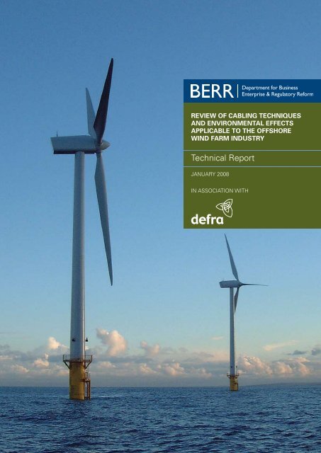
REVIEW OF CABLING TECHNIQUES<br />
AND ENVIRONMENTAL EFFECTS<br />
APPLICABLE TO THE OFFSHORE<br />
WIND FARM INDUSTRY<br />
Technical Report<br />
JANUARY 2008<br />
IN ASSOCIATION WITH
Contents<br />
1 Introduction 11<br />
1.1 Background 11<br />
1.2 Study Description 12<br />
1.3 Report Format 13<br />
2 Legislation 15<br />
2.1 Introduction 15<br />
2.2 Licences <strong>and</strong> Consents 15<br />
3 Cable types <strong>and</strong> installation techniques 18<br />
3.1 Introduction 18<br />
3.2 Cable Types 18<br />
3.3 Offshore Wind Farm Cables 18<br />
3.4 Telecoms Cables 22<br />
3.5 Power Cables 26<br />
3.6 Flowlines, Umbilicals <strong>and</strong> Small Diameter Pipelines 27<br />
3.7 Background to Safe Installation <strong>and</strong> Protection <strong>of</strong> Subsea Cables 27<br />
3.8 Cable Protection Methods 34<br />
3.9 Cable Protection for Offshore Wind Farm Developments 70<br />
3.10 Burial Assessment <strong>and</strong> General Survey <strong>Techniques</strong> 77<br />
3.11 Decommissioning 78<br />
4 Physical change 80<br />
4.1 Introduction 80<br />
4.2 Site Conditions 80<br />
4.3 Level <strong>of</strong> Sediment Disturbance 82<br />
4.4 Seabed Disturbance by Other Activities 89<br />
4.5 Dispersal <strong>and</strong> Re-Deposition <strong>of</strong> Sediment 90<br />
4.6 Mitigation Measures 99<br />
5 Potential impacts <strong>and</strong> mitigation measures 101<br />
5.1 Introduction 101<br />
5.2 Subtidal Ecology 102<br />
5.3 Intertidal Habitats 110<br />
5.4 Natural Fish Resource 113<br />
5.5 Commercial Fisheries 121<br />
5.6 Marine Mammals 125<br />
5.7 Ornithology 128<br />
5.8 Shipping <strong>and</strong> Navigation 131<br />
5.9 Seascape <strong>and</strong> Visual Character 133<br />
5.10 Marine <strong>and</strong> Coastal Archaeology 134<br />
6 Good practice measures 138<br />
7 Gaps in underst<strong>and</strong>ing 140<br />
8 References 142<br />
Appendix A: St<strong>and</strong>ards <strong>and</strong> codes <strong>of</strong> practice relevant to<br />
cable installation & the Offshore wind industry 154<br />
1
<strong>Review</strong> <strong>of</strong> <strong>Cabling</strong> <strong>Techniques</strong> <strong>and</strong> <strong>Environmental</strong> <strong>Effects</strong> <strong>Applicable</strong> to the Offshore Wind<br />
Farm Industry – Technical Report<br />
Acknowledgements<br />
This report was prepared by consultants from Royal Haskoning <strong>and</strong> BOMEL<br />
Ltd. The principal contributors from Royal Haskoning were Dr Samantha Vize,<br />
Christine Adnitt, Robert Stanil<strong>and</strong>, Julia Everard, Alec Sleigh, Rod Cappell, Sean<br />
McNulty <strong>and</strong> Dr Martin Budd. From BOMEL Ltd, the principal contributors were<br />
Ian Bonnon <strong>and</strong> John Carey.<br />
This report has benefited from assistance from Adrian Judd at the Centre <strong>of</strong><br />
Fisheries, Environment <strong>and</strong> Aquaculture Science (CEFAS). The authors also wish<br />
to thank the following consultees:<br />
Natural Engl<strong>and</strong> (Louise Burton, Victoria Copley, Keith Henson, Sarah S<strong>of</strong>fe <strong>and</strong><br />
Michael Young)<br />
English Heritage (Dr Chris Pater)<br />
Countryside Council for Wales (Dr Sarah Wood)<br />
Joint Nature Conservation Committee (Zoe Crutchfield <strong>and</strong> Andrew Prior)<br />
These consultees have assisted in providing comments on the principles <strong>of</strong><br />
the study via correspondence. Their citation here does not indicate current<br />
agreement or support <strong>of</strong> the study outputs.<br />
The research leading to the publication <strong>of</strong> this report was funded by:<br />
●<br />
●<br />
2<br />
Department for Business, Enterprise <strong>and</strong> Regulatory Reform; <strong>and</strong><br />
Department for Environment, Food <strong>and</strong> Rural Affairs.<br />
The project was managed by Dr John Hartley <strong>of</strong> Hartley Anderson Ltd on behalf<br />
<strong>of</strong> the Department Business, Enterprise <strong>and</strong> Regulatory Reform.<br />
The Target Audience<br />
This report is intended to provide technical details on subsea cable installation<br />
techniques <strong>and</strong> associated potential environmental effects, particularly relating<br />
to the <strong>of</strong>fshore wind farm industry. It aims to inform wind farm developers (<strong>and</strong><br />
their consultants), stakeholders <strong>and</strong> regulators during the <strong>Environmental</strong> Impact<br />
Assessment (EIA) stage <strong>and</strong> consents process.
Summary<br />
In the UK today, wind farms are the most developed technology for the<br />
large scale production <strong>of</strong> renewable energy <strong>of</strong>fshore. Given their position<br />
away from l<strong>and</strong>-based urban development, <strong>of</strong>fshore wind farms can be more<br />
substantial in terms <strong>of</strong> their area <strong>and</strong> power generation, compared to their l<strong>and</strong>based<br />
counterparts. Public support for <strong>of</strong>fshore wind farms is generally high,<br />
particularly where evidence is presented through the formal consenting <strong>and</strong><br />
consultation processes that developments are sited in an appropriate location,<br />
where environmental <strong>and</strong> negative economic effects are minimal or can be<br />
effectively managed.<br />
Integral to <strong>of</strong>fshore wind farm development is the installation, operation <strong>and</strong><br />
maintenance <strong>of</strong> the supporting electrical infrastructure <strong>of</strong> intra-array <strong>and</strong> export<br />
cables. This document aims to provide an information resource, intended for<br />
use by wind farm developers, consultants <strong>and</strong> regulators, on the range <strong>of</strong> cable<br />
installation techniques available, their likely environmental effects <strong>and</strong> potential<br />
mitigation, drawing on wind farm <strong>and</strong> other marine industry practice <strong>and</strong><br />
experience. Through the collation <strong>of</strong> existing information <strong>and</strong> experience from a<br />
range <strong>of</strong> sources, the report will assist government, developers, stakeholders <strong>and</strong><br />
regulators during the formal <strong>Environmental</strong> Impact Assessment <strong>and</strong> consenting<br />
process including stages <strong>of</strong> information provision, review <strong>and</strong> approval <strong>of</strong> such<br />
information. Importantly, an underst<strong>and</strong>ing <strong>of</strong> the difficulties <strong>and</strong> constraints <strong>of</strong><br />
cable installation has been provided such that impacts can be avoided, reduced<br />
or minimised. This document also deals with the practical application <strong>of</strong> the<br />
installation <strong>and</strong> mitigation techniques available to developers so that the most<br />
relevant <strong>and</strong> up-to-date technology can be applied in the most appropriate<br />
situation.<br />
This document covers:<br />
●<br />
●<br />
●<br />
The range <strong>of</strong> types <strong>of</strong> cables <strong>and</strong> small diameter pipelines currently installed<br />
in the EU shelf marine environment. Details are given for the types <strong>of</strong> cable<br />
typically used for <strong>of</strong>fshore wind farms <strong>and</strong> also the types <strong>of</strong> cable commonly<br />
used in the telecommunications <strong>and</strong> power cable industries.<br />
The range <strong>of</strong> techniques used to install <strong>and</strong> maintain the aforementioned<br />
cables <strong>and</strong> pipelines. Information is provided on a range <strong>of</strong> commonly<br />
applied cable protection measures, <strong>and</strong> also <strong>of</strong> the burial assessment survey<br />
techniques, commonly used before cable installation.<br />
The physical changes or effects to the seabed <strong>and</strong> sub-surface sediments<br />
expected to occur during cabling activities. The range <strong>of</strong> sediment types likely<br />
to be encountered during cable burial operations is discussed, with the level<br />
<strong>of</strong> sediment disturbance that is likely to occur during cable burial for each<br />
technique.<br />
3
<strong>Review</strong> <strong>of</strong> <strong>Cabling</strong> <strong>Techniques</strong> <strong>and</strong> <strong>Environmental</strong> <strong>Effects</strong> <strong>Applicable</strong> to the Offshore Wind<br />
Farm Industry – Technical Report<br />
●<br />
●<br />
●<br />
●<br />
4<br />
The potential environmental impacts that could occur during the installation<br />
<strong>and</strong> maintenance <strong>of</strong> subsea cables. Impacts are described <strong>and</strong> discussed<br />
for intertidal habitats, subtidal ecology, natural fish resources, commercial<br />
fisheries, marine mammals, ornithology, shipping <strong>and</strong> navigation, seascape<br />
<strong>and</strong> visual character, <strong>and</strong> marine <strong>and</strong> coastal archaeology. Impacts are<br />
divided into those that could cause potentially significant impacts <strong>and</strong> those<br />
that may arise but are unlikely to cause significant effects.<br />
Mitigation measures that can be used to reduce the level <strong>of</strong> significance <strong>of</strong><br />
environmental effects.<br />
Examples <strong>of</strong> good practice measures that could be adopted during all phases<br />
<strong>of</strong> project planning <strong>and</strong> used in conjunction with mitigation measures to<br />
reduce potential disturbance from cabling activities; <strong>and</strong><br />
Knowledge gaps identified during this review, including gaps in underst<strong>and</strong>ing<br />
<strong>of</strong> the actual environmental impacts resulting from cable burial activities.<br />
The key impacts relating to cable laying in the marine environment occur during<br />
the installation process. Cable burial <strong>and</strong> other protection measures (i.e. outer<br />
protective cable armouring, concrete <strong>and</strong> frond mattresses, rock dumping, <strong>and</strong><br />
grout / s<strong>and</strong> bags) are used in order to reduce the risk <strong>of</strong> damage to the cable<br />
<strong>and</strong> to ensure the safety <strong>of</strong> other users <strong>of</strong> the sea. Where cables are not afforded<br />
adequate protection, damage can occur through abrasion (i.e. on rocky seabed<br />
types) <strong>and</strong> interaction with human activities such as snagging or entanglement<br />
from bottom trawl fishing gear, anchoring or navigational dredging.<br />
Dependant upon prevailing conditions <strong>of</strong> depth, seabed morphology,<br />
hydrodynamics <strong>and</strong> geology, a range <strong>of</strong> cable burial technology is available<br />
to developers, such as cable ploughs, tracked burial machines, free swimming<br />
remotely operated vehicles (ROVs) <strong>and</strong> burial sleds.<br />
Induced changes to the prevailing physical conditions <strong>of</strong> an area, such as the<br />
suspension, dispersal <strong>and</strong> subsequent deposition <strong>of</strong> seabed sediments, changes<br />
to seabed morphology <strong>and</strong> the direct impacts associated with the presence <strong>and</strong><br />
operation <strong>of</strong> cable burial equipment can lead to a range <strong>of</strong> potential environmental<br />
impacts. The nature, extent <strong>and</strong> significance <strong>of</strong> these impacts will be a function<br />
<strong>of</strong> site specific characteristics (i.e. seabed type, tidal <strong>and</strong> wave conditions) <strong>and</strong><br />
the chosen installation method. The key potential environmental impacts, which<br />
can, in specific circumstances, be associated with cable burial, include:<br />
●<br />
●<br />
●<br />
Disturbance to sessile, encrusting, <strong>and</strong> attached fauna <strong>and</strong> flora which can be<br />
dislodged/disturbed;<br />
Smothering <strong>of</strong> sessile species due to increased sediment deposition <strong>and</strong> sidecast;<br />
Damage to the filtering mechanisms <strong>of</strong> certain species, the gills <strong>of</strong> sensitive<br />
fish species <strong>and</strong> eggs <strong>and</strong> larvae from increases in suspended sediment <strong>and</strong><br />
subsequent deposition;
●<br />
●<br />
●<br />
●<br />
●<br />
●<br />
●<br />
●<br />
●<br />
●<br />
The potential release <strong>of</strong> contaminants, previously retained in the sediment;<br />
Disturbance to important fisheries habitats such as spawning grounds,<br />
nursery grounds, feeding grounds, over-wintering areas for crustaceans,<br />
migration routes <strong>and</strong> shellfish beds;<br />
Disturbance to sensitive habitats, such as saltmarshes, biogenic reefs <strong>and</strong> eel<br />
grass beds;<br />
Noise <strong>and</strong> vibration impacts to fish <strong>and</strong> marine mammals;<br />
Electromagnetic field generation impacts to benthic species, fish <strong>and</strong> marine<br />
mammals;<br />
Risk <strong>of</strong> collision <strong>of</strong> marine mammals with cable installation vessels / support<br />
vessels; marine mammals may be disturbed by the presence <strong>of</strong> vessels <strong>and</strong><br />
cable burial equipment; <strong>and</strong>, cable entanglement with marine mammals;<br />
Marine <strong>and</strong> coastal bird species, particularly at sites <strong>of</strong> importance to nature<br />
conservation, may be disturbed by the presence <strong>of</strong> vessels <strong>and</strong> human<br />
activities;<br />
Navigational risks such as collision with cable installation vessels;<br />
Direct loss or disturbance to artefacts <strong>of</strong> importance to marine <strong>and</strong> coastal<br />
archaeology <strong>and</strong> cultural heritage; <strong>and</strong><br />
Seascape <strong>and</strong> visual impacts related to the cable installation activities <strong>and</strong><br />
the presence <strong>of</strong> cable installation vessels; <strong>and</strong> possible sea surface aesthetic<br />
effects arising from sediment plumes, particularly in areas <strong>of</strong> chalk bedrock.<br />
This study concludes that, although cabling can cover large areas <strong>of</strong> seabed, the<br />
associated environmental impacts are highly transitory, localised in extent <strong>and</strong><br />
temporary in duration. Although the corridor for cable installation impacts can<br />
be long, the footprint <strong>of</strong> impact is narrow, generally restricted to 2-3m width. For<br />
the majority <strong>of</strong> installation scenarios, the seabed <strong>and</strong> associated fauna <strong>and</strong> flora<br />
would be expected to return to a state similar to the pre-disturbance conditions.<br />
Exceptions could occur in hard clays <strong>and</strong> rock seabed types, where the cable<br />
trench would not naturally backfill, requiring intervention to backfill as part <strong>of</strong><br />
construction works or else leaving permanent scarring <strong>of</strong> the seabed.<br />
The environmental impacts associated with the installation, operation <strong>and</strong><br />
maintenance <strong>of</strong> cables associated with <strong>of</strong>fshore wind farms must be considered<br />
in the context <strong>of</strong> other influencing factors. Natural perturbations such as storm<br />
activity can have a significant effect on the structure <strong>and</strong> functioning <strong>of</strong> the<br />
seabed, as can other activities such as oil <strong>and</strong> gas exploration <strong>and</strong> infrastructure,<br />
telecommunication cable installations, certain fishing activities, aggregate<br />
extraction, <strong>and</strong> other sources <strong>of</strong> change to the physical environment. In many<br />
cases, such influencing factors may lead to related environmental impacts <strong>of</strong><br />
greater extent, duration <strong>and</strong> significance than those observed or suspected to<br />
arise as a result <strong>of</strong> the installation <strong>of</strong> <strong>of</strong>fshore wind farm cable infrastructure.<br />
5
Abbreviations<br />
AIS Automatic Identification System<br />
AONB Area <strong>of</strong> Outst<strong>and</strong>ing Natural Beauty<br />
AoSP Areas <strong>of</strong> Special Protection<br />
BAS Burial Assessment Survey<br />
BERR Department for Business, Enterprise <strong>and</strong> Regulatory Reform<br />
BETTA British Trading <strong>and</strong> Transmission Arrangements<br />
BWEA British Wind Energy Association<br />
BS British St<strong>and</strong>ards<br />
BSC Balancing <strong>and</strong> Settlement Code<br />
CEFAS Centre for Environment, Fisheries <strong>and</strong> Aquaculture<br />
CIRIA Construction Industry Research <strong>and</strong> Information Association<br />
CIWEM Chartered Institute <strong>of</strong> Water <strong>and</strong> <strong>Environmental</strong> Management<br />
CMACS Centre for Marine <strong>and</strong> Coastal Studies<br />
COWRIE Collaborative Offshore Wind Research into the Environment<br />
CPA Coast Protection Act (1949)<br />
CRoW Countryside <strong>and</strong> Rights <strong>of</strong> Way Act (2000)<br />
CUSC Connection <strong>and</strong> Use <strong>of</strong> Systems Code<br />
DEFRA Department for Environment, Food <strong>and</strong> Rural Affairs<br />
DNO Distribution Network Operator<br />
DNV Det Norske Veritas<br />
DSV Dive Support Vessel<br />
DTI Department <strong>of</strong> Trade <strong>and</strong> Industry<br />
EA Electricity Act (1989)<br />
EHS Environment <strong>and</strong> Heritage Service (Northern Irel<strong>and</strong>)<br />
EIA <strong>Environmental</strong> Impact Assessment<br />
EMF Electro Magnetic Field<br />
ENA Electricity Networks Association<br />
ES <strong>Environmental</strong> Statement<br />
EU European Union<br />
FEPA Food <strong>and</strong> Environment Protection Act (1985)<br />
GCR Geological Conservation <strong>Review</strong><br />
7
<strong>Review</strong> <strong>of</strong> <strong>Cabling</strong> <strong>Techniques</strong> <strong>and</strong> <strong>Environmental</strong> <strong>Effects</strong> <strong>Applicable</strong> to the Offshore Wind<br />
Farm Industry – Technical Report<br />
HAP Habitat Action Plan<br />
HSE Health & Safety Executive<br />
HVDC High Voltage Direct Current<br />
IEC International Electro-technical Commission<br />
IEEE Institute <strong>of</strong> Electrical <strong>and</strong> Electronics Engineers<br />
ISO International Organisation for St<strong>and</strong>ardisation<br />
JNAPC Joint Nautical Archaeology Policy Committee<br />
JNCC Joint Nature Conservation Committee<br />
LWM Low Water Mark<br />
MCA Maritime <strong>and</strong> Coastguard Agency<br />
MCEU Marine Consents <strong>and</strong> Environment Unit<br />
MCGA Marine <strong>and</strong> Coastguard Agency<br />
MEHRA Marine <strong>Environmental</strong> High Risk Area<br />
MESH Mapped European Seabed Habitats<br />
MHWS Mean High Water Springs<br />
MLWS Mean Low Water Springs<br />
MNR Marine Nature Reserve<br />
MSPP Marine Spatial Planning Pilot<br />
NNR National Nature Reserve<br />
ORCU Offshore Renewables Consents Unit<br />
OREI Offshore Renewable Energy Installations<br />
PIANC Permanent International Association <strong>of</strong> Navigation Congresses<br />
REZ Renewable Energy Zone<br />
ROV Remotely Operated Vehicle<br />
RSPB Royal Society for the Protection <strong>of</strong> Birds<br />
SAC Special Area <strong>of</strong> Conservation<br />
SAP Species Action Plan<br />
SEA Strategic <strong>Environmental</strong> Assessment<br />
SMA Sensitive Marine Area<br />
SMP Shoreline Management Plan<br />
SPA Special Protection Area<br />
SSSI Site <strong>of</strong> Special Scientific Interest<br />
8
TTS Temporary Threshold Shift<br />
TWA Transport <strong>and</strong> Works Act<br />
UKBAP UK Biodiversity Action Plan<br />
UKOOA United Kingdom Offshore Operators Association<br />
VTS Vessel Traffic Services<br />
WAG Welsh Assembly Government<br />
WSI Written Scheme <strong>of</strong> Investigation<br />
WTG Wind Turbine Generator<br />
Abbreviations<br />
9
1<br />
Introduction<br />
1.1 Background<br />
The UK is committed to working towards a 60% reduction in CO 2 emissions by<br />
2050 <strong>and</strong> the development <strong>of</strong> renewable energy technologies, such as wind, is a<br />
core part <strong>of</strong> achieving this aim. As a carbon free source <strong>of</strong> energy, wind power<br />
contributes positively to the UK’s efforts to reduce our carbon emissions to tackle<br />
the threat <strong>of</strong> climate change (Sustainable Development Commission, 2005). The<br />
UK’s <strong>of</strong>fshore wind energy resource is substantial, estimated at around 100,000<br />
GWh <strong>of</strong> practical resource (Sinden, 2004). Other marine renewables, such as<br />
wave <strong>and</strong> tidal are also rapidly developing sectors <strong>of</strong> the renewable energy<br />
industry.<br />
Whilst many <strong>of</strong> the impacts <strong>of</strong> <strong>of</strong>fshore wind farm developments are becoming<br />
increasingly accepted <strong>and</strong> understood, concerns have been raised about the<br />
potential environmental effects <strong>of</strong> certain cable installation techniques (including<br />
by fishermen <strong>and</strong> country conservation agencies). There is a range <strong>of</strong> potential<br />
cable installation <strong>and</strong> protection technologies but to date, there has been limited<br />
centralised knowledge sharing both within the <strong>of</strong>fshore wind industry <strong>and</strong> from<br />
other more established marine industries, such as subsea telecommunications<br />
<strong>and</strong> oil <strong>and</strong> gas. This lack <strong>of</strong> review <strong>and</strong> synthesis can hinder the consideration <strong>of</strong><br />
<strong>Environmental</strong> Statements <strong>and</strong> adoption <strong>of</strong> best practice by developers involved<br />
in the area <strong>of</strong> marine renewables.<br />
The installation, operation <strong>and</strong> maintenance <strong>of</strong> the supporting electrical<br />
infrastructure <strong>of</strong> inter-array <strong>and</strong> export cables are integral to <strong>of</strong>fshore wind farm<br />
development. A range <strong>of</strong> methods for cable installation are available to wind<br />
farm operators, the most applicable being dependant upon prevailing conditions<br />
<strong>of</strong> depth, seabed morphology, hydrodynamics <strong>and</strong> geology. These site specific<br />
characteristics <strong>and</strong> the chosen installation method subsequently manifest a<br />
range <strong>of</strong> impacts on the surrounding environment, the nature <strong>and</strong> extent <strong>of</strong><br />
which can vary significantly.<br />
11
<strong>Review</strong> <strong>of</strong> <strong>Cabling</strong> <strong>Techniques</strong> <strong>and</strong> <strong>Environmental</strong> <strong>Effects</strong> <strong>Applicable</strong> to the Offshore Wind<br />
Farm Industry – Technical Report<br />
Figure 1.0 Scroby S<strong>and</strong>s <strong>of</strong>fshore wind farm<br />
(Photo courtesy <strong>of</strong> Vestas Wind Systems A/S)<br />
1.2 Study Description<br />
A large number <strong>of</strong> cables associated with energy production, telecommunications<br />
<strong>and</strong> oil <strong>and</strong> gas extraction are already located on or under the seabed <strong>of</strong> the<br />
UK continental shelf. The effects <strong>of</strong> laying these cables have been investigated<br />
to varying degrees <strong>and</strong>, as such, a great deal <strong>of</strong> experience <strong>and</strong> previous<br />
knowledge has already been gathered <strong>and</strong> is held by various industries,<br />
government departments <strong>and</strong> research organisations etc. As with many sectoral<br />
developments, particularly in the marine environment, this information has not<br />
been widely disseminated, reviewed or synthesised for a wider audience or been<br />
made publicly available.<br />
Consequently, the Research Advisory Group on Offshore Renewable Installations<br />
identified a need for Guidance on seabed installation techniques <strong>and</strong> their<br />
potential environmental effects. This guidance is required principally to inform<br />
wind farm developers <strong>and</strong> others during the <strong>Environmental</strong> Impact Assessment<br />
(EIA) <strong>and</strong> determination stages <strong>of</strong> the consents process. The guidance will be<br />
equally <strong>of</strong> use to other burgeoning marine renewable energy technologies, such<br />
as wave <strong>and</strong> tidal.<br />
1.2.1 STUDY AIMS<br />
The study aims to provide an information resource <strong>and</strong> guidance to government<br />
<strong>and</strong> developers on the range <strong>of</strong> cable installation techniques available, their<br />
12
Introduction<br />
likely environmental effects <strong>and</strong> potential mitigation, drawing on wind farm <strong>and</strong><br />
other marine industry practice <strong>and</strong> experience.<br />
Through the collation <strong>of</strong> existing information <strong>and</strong> experience from a range<br />
<strong>of</strong> sources, the guidance will assist government, developers, stakeholders<br />
<strong>and</strong> regulators during the EIA <strong>and</strong> consenting process including stages <strong>of</strong><br />
information provision, review <strong>and</strong> approval <strong>of</strong> such information. Importantly,<br />
an underst<strong>and</strong>ing <strong>of</strong> the difficulties <strong>and</strong> constraints <strong>of</strong> cable installation has<br />
been provided such that impacts can be avoided, reduced or minimised. This<br />
document also deals with the practical application <strong>of</strong> the installation <strong>and</strong><br />
mitigation techniques available to developers so that the most relevant <strong>and</strong><br />
up-to-date technology can be applied in the most appropriate situation.<br />
In summary, the specific objectives for this project are as follows:<br />
●<br />
●<br />
●<br />
●<br />
To summarise the range <strong>of</strong> types <strong>of</strong> cables <strong>and</strong> small diameter pipelines<br />
currently installed in the EU shelf marine environment;<br />
To discuss the range <strong>of</strong> techniques used to install <strong>and</strong> maintain the<br />
aforementioned cables <strong>and</strong> pipelines;<br />
To summarise the environmental impacts that could arise as a result <strong>of</strong><br />
these installation <strong>and</strong> maintenance techniques (both reported <strong>and</strong> potential<br />
impacts); <strong>and</strong><br />
To produce a technical report document which reviews cabling techniques<br />
<strong>and</strong> their environmental effects for use in the development <strong>of</strong> wind farm<br />
projects (<strong>and</strong> other marine renewable technologies).<br />
1.3 Report Format<br />
Section 1 describes the project’s background, aims <strong>and</strong> objectives.<br />
Section 2 outlines the relevant legislation applicable to the development <strong>of</strong><br />
<strong>of</strong>fshore wind farms <strong>and</strong> the installation/maintenance <strong>of</strong> cables/pipelines.<br />
Section 3 summarises the types <strong>of</strong> cables <strong>and</strong> pipelines that are currently<br />
installed in the marine environment <strong>and</strong> the range <strong>of</strong> installation techniques<br />
that are available. The relevant characteristics <strong>of</strong> each type are provided, such<br />
as dimensions, construction material, armouring, depth <strong>of</strong> burial, additional<br />
protection measures, normal service life <strong>and</strong> decommissioning. The range <strong>of</strong><br />
installation techniques that are available are also described as well as the type<br />
<strong>of</strong> engineering st<strong>and</strong>ards <strong>and</strong> constraints that might be <strong>of</strong> relevance (i.e. depth<br />
<strong>of</strong> burial in areas <strong>of</strong> sediment movement or where beam trawling occurs).<br />
Section 4 outlines the physical changes or effects to the seabed <strong>and</strong> surface<br />
sediments that could be expected to occur during cabling activity <strong>and</strong> the key<br />
characteristics that influence the extent <strong>of</strong> change.<br />
13
<strong>Review</strong> <strong>of</strong> <strong>Cabling</strong> <strong>Techniques</strong> <strong>and</strong> <strong>Environmental</strong> <strong>Effects</strong> <strong>Applicable</strong> to the Offshore Wind<br />
Farm Industry – Technical Report<br />
Section 5 describes the potential environmental impacts expected during<br />
cabling activities together with possible mitigation measures that could be used<br />
to reduce their scale <strong>of</strong> effect. Impacts are described <strong>and</strong> discussed for:<br />
●<br />
●<br />
●<br />
●<br />
●<br />
●<br />
●<br />
●<br />
●<br />
14<br />
Intertidal habitats;<br />
Subtidal ecology;<br />
Natural fish resource;<br />
Commercial fisheries;<br />
Marine mammals;<br />
Ornithology;<br />
Shipping <strong>and</strong> navigation;<br />
Seascape <strong>and</strong> visual character; <strong>and</strong><br />
Marine <strong>and</strong> coastal archaeology.<br />
Section 6 provides examples <strong>of</strong> good practice measures during cabling activities<br />
which could be adopted in conjunction with mitigation measures to minimise<br />
the magnitude <strong>and</strong> significance <strong>of</strong> effects on the local environment.<br />
Section 7 outlines the gaps in underst<strong>and</strong>ing <strong>and</strong> data identified as part <strong>of</strong> this<br />
project.<br />
Section 8 provides a full reference list.
2 Legislation<br />
2.1 Introduction<br />
This section provides an overview <strong>of</strong> the key UK legislation regulating<br />
developmental activities during the construction, operation <strong>and</strong> decommissioning<br />
phases <strong>of</strong> cabling activities associated with <strong>of</strong>fshore wind farm developments.<br />
2.2 Licences <strong>and</strong> Consents<br />
A statutory consenting process exists through which <strong>of</strong>fshore renewable<br />
development applications are considered in relation to UK policy aims <strong>and</strong><br />
international obligations. The consenting process is designed to ensure that<br />
each development decision is made on the basis <strong>of</strong> a comprehensive balanced<br />
consideration <strong>of</strong> impacts, both positive <strong>and</strong> negative.<br />
The consents process in Engl<strong>and</strong> <strong>and</strong> Wales is managed by the Department<br />
for Business, Enterprise <strong>and</strong> Regulatory Reform’s (BERR) Offshore Renewables<br />
Consents Unit (ORCU) <strong>and</strong> other statutory consenting authorities (the Department<br />
for the Environment, Food <strong>and</strong> Rural Affairs (Defra), the Department for Transport<br />
(DfT) <strong>and</strong> the National Assembly for Wales (NAW)). The Scottish Executive is<br />
responsible for administering the consents process for <strong>of</strong>fshore wind farms in<br />
Scottish waters, <strong>and</strong> in Northern Irel<strong>and</strong>, the Department for Enterprise, Trade<br />
<strong>and</strong> Industry (DETI). The above organisations deal with consents received<br />
under the Electricity Act (EA), the Transport <strong>and</strong> Works Act (TWA), Food <strong>and</strong><br />
Environment Protection Act (FEPA) <strong>and</strong> Coast Protection Act (CPA).<br />
The consents process for <strong>of</strong>fshore wind farms, in Engl<strong>and</strong>, Scotl<strong>and</strong> <strong>and</strong> Wales,<br />
is explained in the DTI’s (now BERR) Strategic Planning Framework consultation<br />
paper (2002) <strong>and</strong> full guidance for the consents process is provided within DTI<br />
(now BERR) guidance notes (2004). National Planning Policy Guidelines (NPPG)<br />
6 sets out national planning guidance for renewable energy developments in<br />
Scotl<strong>and</strong> (Scottish Natural Heritage, 2004). In Northern Irel<strong>and</strong>, the DETI has<br />
produced a Strategic Energy Framework for Northern Irel<strong>and</strong> (DETI, 2004) <strong>and</strong><br />
the Department <strong>of</strong> the Environment within the Northern Irel<strong>and</strong> Assembly has<br />
published details on planning process in Planning Policy Statement 1 – ‘General<br />
Principles’ (Department <strong>of</strong> the Environment, 1998).<br />
Under the auspices <strong>of</strong> the Electricity Works (<strong>Environmental</strong> Impact Assessment)<br />
Regulations 2000 (SI 2000/1927), applications for consent for <strong>of</strong>fshore wind<br />
farms (greater than 1MW) must be accompanied by an <strong>Environmental</strong> Statement<br />
(ES), the formal presentation <strong>of</strong> the <strong>Environmental</strong> Impact Assessment process.<br />
In Scotl<strong>and</strong>, this falls under the Electricity Works (<strong>Environmental</strong> Assessment<br />
(Scotl<strong>and</strong>) 2000 Regulations (SI 2000/320) <strong>and</strong> in Northern Irel<strong>and</strong>, the Electricity<br />
(Northern Irel<strong>and</strong>) Order 1992 (SI 1992/231). The ES details the nature <strong>and</strong><br />
extent <strong>of</strong> the potential impacts <strong>of</strong> each aspect <strong>of</strong> the construction, operation<br />
<strong>and</strong> eventual decommissioning <strong>of</strong> the wind farm <strong>and</strong> associated infrastructure.<br />
15
<strong>Review</strong> <strong>of</strong> <strong>Cabling</strong> <strong>Techniques</strong> <strong>and</strong> <strong>Environmental</strong> <strong>Effects</strong> <strong>Applicable</strong> to the Offshore Wind<br />
Farm Industry – Technical Report<br />
It is from the evidence presented in the ES, <strong>and</strong> subsequent critical analysis<br />
by a range <strong>of</strong> appropriate authorities, that the necessary consents are granted<br />
<strong>and</strong> any conditions with regard to mitigation, monitoring <strong>and</strong> best practice are<br />
applied.<br />
Offshore cabling applications <strong>and</strong> <strong>of</strong>fshore wind farm applications require<br />
developers to obtain a number <strong>of</strong> consents. A summary <strong>of</strong> these consents are<br />
set out in Table 2.1. The st<strong>and</strong>ards <strong>and</strong> codes <strong>of</strong> practice necessary for subsea<br />
cabling activities for the development <strong>of</strong> an <strong>of</strong>fshore wind farm are provided in<br />
Appendix A.<br />
Specifically, for cabling activities associated with the <strong>of</strong>fshore wind farm industry,<br />
a FEPA <strong>and</strong> CPA licence is required for:<br />
●<br />
●<br />
16<br />
Installation <strong>of</strong> cables; <strong>and</strong><br />
Deposition <strong>of</strong> material for cable/scour protection purposes such as rock<br />
armouring <strong>and</strong> grout bags.<br />
Under FEPA, the decision as to whether a licence will be granted will depend<br />
on the assessment by the Licensing Authority <strong>of</strong> potential hydrological effects,<br />
risk to fish, mammals <strong>and</strong> other marine life from contaminants, noise <strong>and</strong><br />
vibration, effects from potential increases in turbidity, smothering <strong>and</strong> burial <strong>of</strong><br />
marine life, any adverse implications to designated marine conservation areas<br />
or interference to other marine <strong>and</strong> coastal users.<br />
Under CPA, the Secretary <strong>of</strong> State must determine whether marine works will<br />
be detrimental to the safety <strong>of</strong> navigation in relation to the cabling installation/<br />
removal activities.<br />
Guidance for EIA in respect <strong>of</strong> FEPA <strong>and</strong> CPA requirements is provided by CEFAS<br />
(CEFAS, 2004).<br />
If an <strong>of</strong>fshore wind farm development is planning a high voltage electrical<br />
connection to the onshore grid, then use <strong>of</strong> the transmission assets involved –<br />
the <strong>of</strong>fshore substations, related electrical plant, <strong>and</strong> export cables – will require<br />
a transmission licence under the Electricity Act 1989. A distribution licence would<br />
be required if the electrical connection is at low voltage. These licensing regimes<br />
are currently under development <strong>and</strong> are likely to be introduced in 2008 <strong>and</strong> 2007<br />
respectively. Further information on obtaining licences for <strong>of</strong>fshore transmission<br />
<strong>and</strong>/or distribution can be obtained from the Offshore Transmission Team at<br />
BERR <strong>and</strong> on the BERR website.
Legislation<br />
Table 2.1: Statutory licences <strong>and</strong> consents for <strong>of</strong>fshore wind farms<br />
Act <strong>of</strong> Parliament Consent type Competent Authority<br />
Section 36 – Electricity Act (EA) 1989<br />
(as amended by the Energy Act 2004)<br />
Electricity (Northern Irel<strong>and</strong>) Order<br />
1992<br />
Section 37 – Electricity Act (EA) 1989<br />
Section 5 <strong>and</strong> 6 – Electricity Act (EA)<br />
1989<br />
Section 5 – Food & Environment<br />
Protection Act (FEPA) (Part II) 1985<br />
Section 34 – Coast Protection Act<br />
(CPA) 1949<br />
Section 90 or Section 57 –<br />
Town <strong>and</strong> Country Planning Act 1990<br />
Section 57 or Section 28 – Town <strong>and</strong><br />
Country Planning (Scotl<strong>and</strong>) Act 1997<br />
Section 109 – Water Resource Act<br />
1991<br />
Section 20 – Water Environment <strong>and</strong><br />
Water Services (Scotl<strong>and</strong>) Act 2003<br />
For <strong>of</strong>fshore wind power generating<br />
stations within territorial waters adjacent<br />
to Engl<strong>and</strong> <strong>and</strong> Wales.<br />
For overhead electric power lines<br />
associated with <strong>of</strong>fshore wind farm<br />
projects.<br />
For the transmission or distribution <strong>of</strong><br />
electricity.<br />
For depositing articles or material in<br />
the sea/tidal waters below mean high<br />
water springs (MHWS), including the<br />
placement <strong>of</strong> construction material or<br />
disposal <strong>of</strong> waste dredging.<br />
Construction under or over the seashore<br />
lying below MHWS. To make provision<br />
for the safety <strong>of</strong> navigation in relation to<br />
the export cable route <strong>and</strong> inter-turbine<br />
cabling network<br />
Deemed planning permission sought<br />
as part <strong>of</strong> the Section 36 applications<br />
for the onshore elements <strong>of</strong> the cable<br />
route. Section 57 – planning permission<br />
is sought separately, from the relevant<br />
local planning authority.<br />
To erect a structure e.g. cabling in, over<br />
or under a water course that is part <strong>of</strong> a<br />
main river<br />
Transport <strong>and</strong> Works Act 1992 Relating to <strong>of</strong>fshore generating stations<br />
<strong>and</strong> works which may interfere with<br />
rights <strong>of</strong> navigation.<br />
Source: Adapted from DTI guidance (2004)<br />
BERR (Engl<strong>and</strong> & Wales)<br />
Scottish Executive (Scotl<strong>and</strong>)<br />
DETI (Northern Irel<strong>and</strong>)<br />
Ofgem<br />
Marine Consents Environment<br />
Unit (MCEU) <strong>of</strong> DEFRA<br />
Environment <strong>and</strong><br />
Heritage Service (EHS)<br />
<strong>of</strong> the Department <strong>of</strong> the<br />
Environment (DOENI)<br />
Scottish Office <strong>of</strong> Agriculture,<br />
Environment <strong>and</strong> Fisheries<br />
Department (SOAEFD)<br />
MCEU<br />
EHS (DOENI)<br />
SOAEFD<br />
BERR (Engl<strong>and</strong> & Wales)<br />
Scottish Executive (Scotl<strong>and</strong>)<br />
DETINI (Northern Irel<strong>and</strong>)<br />
Environment Agency<br />
(Engl<strong>and</strong> <strong>and</strong> Wales)<br />
Scottish Environment<br />
Protection Agency (SEPA)<br />
(Scotl<strong>and</strong>)<br />
Rivers Agency (Northern<br />
Irel<strong>and</strong>)<br />
BERR (Engl<strong>and</strong> & Wales)<br />
Scottish Executive (Scotl<strong>and</strong>)<br />
DETINI (Northern Irel<strong>and</strong>)<br />
17
3 Cable types <strong>and</strong><br />
18<br />
installation techniques<br />
3.1 Introduction<br />
This section <strong>of</strong> the report lists all <strong>of</strong> the cable types which are anticipated to be<br />
used in the near future for <strong>of</strong>fshore wind farm development work <strong>and</strong> sets the<br />
background to the methodologies which have been developed in other industries<br />
for the safe installation <strong>and</strong> protection <strong>of</strong> subsea cables. It then outlines the<br />
various cable protection methods, including all <strong>of</strong> the various cable burial<br />
methodologies together with details <strong>of</strong> alternative external cable protection<br />
systems. This includes details <strong>of</strong> the cable protection methods which are most<br />
applicable <strong>and</strong> relevant for the <strong>of</strong>fshore wind farm industry. Information on<br />
burial assessment survey techniques which are commonly used as a pre-survey<br />
activity before the main cable installation is included. Finally, this section reviews<br />
how legislation on decommissioning <strong>of</strong> the installed cable systems could also<br />
give rise to procedures which could have an impact on the environment.<br />
3.2 Cable Types<br />
3.2.1 GENERAL<br />
This section <strong>of</strong> the report contains details <strong>of</strong> <strong>of</strong>fshore subsea cables which would<br />
typically be used for <strong>of</strong>fshore wind farms. It also contains details <strong>of</strong> the cables<br />
which are commonly used in the subsea telecommunications <strong>and</strong> power cable<br />
industries.<br />
The design <strong>and</strong> construction <strong>of</strong> a particular subsea cable will be directly governed<br />
by the functionality <strong>of</strong> the cable <strong>and</strong> any requirement to protect the cable from<br />
any potential hostile seabed intervention. Figure 3.1 illustrates a typical range<br />
<strong>and</strong> size <strong>of</strong> cables which can be used for a variety <strong>of</strong> different applications. Some<br />
<strong>of</strong> the cables included in this figure are not all subsea cables.<br />
3.3 Offshore Wind Farm Cables<br />
3.3.1 GENERAL<br />
The design <strong>of</strong> subsea cable systems for <strong>of</strong>fshore wind farms will be influenced<br />
by a number <strong>of</strong> factors. Some <strong>of</strong> the factors are generic, while others are projectspecific:
●<br />
●<br />
●<br />
●<br />
Cable types <strong>and</strong> installation techniques<br />
Connection voltage – Offshore wind farm projects need to be connected to<br />
regional distribution networks, rather than to the national transmission system.<br />
In Engl<strong>and</strong> <strong>and</strong> Wales, these distribution networks currently include 132kV<br />
<strong>and</strong> 33kV systems. Some <strong>of</strong> the early Round 1 <strong>of</strong>fshore wind farm projects<br />
have made connections at 33kV while several others have connections at<br />
132kV. It is probable that all Round 2 sites will secure connections at 132kV.<br />
Cable design – Three-core subsea cables using solid insulation (ERP or XLPE)<br />
are typically used for operation at voltages up to 132kV. Higher voltage cables<br />
that use oil as an insulating medium are not deemed to be environmentally<br />
acceptable owing to the potential risks associated with oil leakage in the<br />
near shore environment. The cables are typically designed to give a power<br />
transmission capacity <strong>of</strong> up to 40MW for a single 33kV cable <strong>and</strong> 160MW for<br />
a single 132kV cable.<br />
Turbine size – Offshore wind farm developers are continually looking to the<br />
turbine manufacturers to develop larger <strong>and</strong> more energy efficient turbines.<br />
The early UK Round 1 developments such as North Hoyle, used 2.5MW wind<br />
turbine generators (WTGs). Current <strong>of</strong>fshore wind farm developments are<br />
planning to use 3.0MW <strong>and</strong> 3.6MW machines <strong>and</strong> plans for a 5.0MW machine<br />
are already well advanced.<br />
Distance from shore – The use <strong>of</strong> a single 132kV cable to shore provides a<br />
cost-effective alternative to the use <strong>of</strong> three or four 33kV cables. The installed<br />
cost (per kilometre) <strong>of</strong> a single 132kV cable is considerably lower than the<br />
installed cost <strong>of</strong> three 33kV cables, but this solution requires an <strong>of</strong>fshore<br />
substation in order to step up to 132kV from the wind farm collection voltage<br />
(usually 33kV). Some <strong>of</strong> the current projects under consideration have more<br />
than one 132kV export cable to link the <strong>of</strong>fshore wind farm to shore.<br />
19
<strong>Review</strong> <strong>of</strong> <strong>Cabling</strong> <strong>Techniques</strong> <strong>and</strong> <strong>Environmental</strong> <strong>Effects</strong> <strong>Applicable</strong> to the Offshore Wind<br />
Farm Industry – Technical Report<br />
Figure 3.1: Diverse Range <strong>of</strong> Different Cable Types<br />
3.3.2 EXPORT CABLES<br />
The function <strong>of</strong> the export cables is to transmit the electrical power from the<br />
<strong>of</strong>fshore wind farm to the appropriate cable connection facility at the shoreline<br />
or l<strong>and</strong>fall. The electrical parameters <strong>of</strong> these cables will depend on the choice<br />
made between two options:<br />
Option 1 – No voltage step-up <strong>of</strong>fshore. The power produced from the <strong>of</strong>fshore<br />
wind farm is transmitted to shore at the collection system voltage. With this<br />
option there is no need for an <strong>of</strong>fshore substation. A number <strong>of</strong> the <strong>of</strong>fshore<br />
turbine structures act as a localised hub from which the export cables then<br />
transmit the generated power back to shore.<br />
Option 2 – Voltage step-up <strong>of</strong>fshore. The power produced by the wind farm<br />
is transmitted to shore at a different voltage level, greater than the collection<br />
voltage. An <strong>of</strong>fshore substation, containing one or more step-up transformers,<br />
is required. The <strong>of</strong>fshore substation acts as the collection point within the wind<br />
farm. The export cables then run from the <strong>of</strong>fshore substation to shore.<br />
20
Cable types <strong>and</strong> installation techniques<br />
High voltage direct current (HVDC) is not economically viable at present due to<br />
the high cost <strong>of</strong> HVDC converters, however it may, in the future, be used for sites<br />
situated further <strong>of</strong>fshore.<br />
The current <strong>and</strong> future generation <strong>of</strong> export cables are likely to be rated with<br />
a voltage <strong>of</strong> 132kV. The cable is likely to be constructed with 3 core copper<br />
conductors, insulation <strong>and</strong> conductor screening, steel wire armour <strong>and</strong> either<br />
ERP or XLPE insulation with a lead sheath. The copper conductor size is typically<br />
estimated at between 300mm 2 <strong>and</strong> 1200mm 2 . The cables will contain optical<br />
fibres embedded between the cores for data transmission <strong>and</strong> communications.<br />
The range <strong>of</strong> indicative cable conductor sizes <strong>and</strong> overall dimensions which<br />
could be used for a 132kV export cable for an <strong>of</strong>fshore wind farm are shown in<br />
Table 3.1.<br />
Table 3.1: Typical Cable Characteristics For 132kv Cable<br />
Details 132kV Cable Type<br />
300 mm² 500 mm² 800 mm² 1000 mm² 1200 mm²<br />
Overall Diameter (mm) 185 193 214 227 232<br />
Weight (kg/m) 58 68 88 100 108<br />
MVA (approx) 127 157 187 200 233<br />
3.3.3 INTER-TURBINE ARRAY CABLES<br />
The inter-turbine array cables are the cables which connect the <strong>of</strong>fshore turbines<br />
into arrays <strong>and</strong> also connect the various arrays together. It is normal practice<br />
to cable several turbines together in an array, with each cable providing a link<br />
between two adjacent turbines. Each end <strong>of</strong> the cable is terminated onto the<br />
high voltage (HV) switchgear located within the turbine tower. Because they<br />
connect to the HV switchgear at the turbines, the operating voltage for the<br />
inter-turbine cables is limited to 36kV. These cables would also connect any<br />
<strong>of</strong>fshore substation to the <strong>of</strong>fshore WTG arrays. The cables between WTGs are<br />
relatively short in length (typically in the range 500m to 950m). However, the<br />
cables between the <strong>of</strong>fshore substation <strong>and</strong> the WTG arrays could be longer <strong>and</strong><br />
possibly up to 3.0km.<br />
The inter-turbine array cables will typically be 33kV, 3-core copper conductors<br />
with insulation/conductor screening <strong>and</strong> steel wire armoured. The insulation<br />
will be either dry type XLPE, wet type XLPE or a combination <strong>of</strong> both. All cables<br />
will contain optical fibres embedded between the cores. A number <strong>of</strong> conductor<br />
sizes would be used depending on the load current that the cable is required to<br />
carry. The ranges <strong>of</strong> indicative cable conductor sizes <strong>and</strong> overall diameters that<br />
may be used are shown in Table 3.2.<br />
21
<strong>Review</strong> <strong>of</strong> <strong>Cabling</strong> <strong>Techniques</strong> <strong>and</strong> <strong>Environmental</strong> <strong>Effects</strong> <strong>Applicable</strong> to the Offshore Wind<br />
Farm Industry – Technical Report<br />
Table 3.2: Typical Cable Characteristics for 33kV cables<br />
Details 33kV Cable Type<br />
22<br />
95 mm² 240 mm² 400 mm² 630 mm² 800 mm²<br />
Overall Diameter (mm) 89 104 127 143 153<br />
Weight (kg/m) 12.2 18.6 38 49 59<br />
MVA (approx) 18 29 36 44 48<br />
3.4 Telecoms Cables<br />
This section outlines the types <strong>of</strong> cables which are commonly used by the subsea<br />
telecommunications industry to install their networks on a worldwide basis. It is<br />
normal practice for the subsea telecommunications industry to conduct a Burial<br />
Assessment Survey in advance <strong>of</strong> the design <strong>of</strong> the cable type along the full route<br />
<strong>of</strong> the cable (see Section 3.10). The Burial Assessment Survey will be used to<br />
assess the level <strong>of</strong> armouring required for a section <strong>of</strong> the cable length together<br />
with the proposed depth <strong>of</strong> burial. Many <strong>of</strong> these cable systems can be in excess<br />
<strong>of</strong> thous<strong>and</strong>s <strong>of</strong> kilometres in length, therefore, the design <strong>of</strong> armouring for the<br />
cable can have a significant influence on the overall cost <strong>of</strong> the cable. There is also<br />
a relationship between the design <strong>of</strong> outer protective armouring <strong>and</strong> the proposed<br />
depth <strong>of</strong> burial to protect the cable in its in-service condition. Hence, the results<br />
<strong>of</strong> the Burial Assessment Survey are used to identify what level <strong>of</strong> burial can be<br />
achieved along the cable route. This assessment will take into account the burial<br />
system to be employed on the project together with the design armouring for the<br />
cable.<br />
Section 3.10 <strong>of</strong> this report reviews Burial Assessment Surveys in more detail.<br />
Table 3.3 gives typical armoured cable characteristics for a number <strong>of</strong> subsea<br />
telecommunication cables. The characteristics <strong>of</strong> these cables are set out in<br />
detail in the following sub-sections.<br />
Table 3.3: Typical Characteristic for Subsea Telecommunication Cables<br />
Characteristic Unit Lightweight<br />
Armour<br />
(AL)<br />
Single<br />
Armour<br />
(A)<br />
Double<br />
Armour<br />
(AA)<br />
Lightweight cable diameter mm 21.5 21.5 21.5<br />
First lay steel wire diameter mm 4.0 4.9 4.9<br />
Number <strong>of</strong> steel armour wires in the lay 19 16 16<br />
Pitch <strong>of</strong> armour wire mm 530 539 539<br />
Second lay mild steel wire diameter mm - - 7.0<br />
Number <strong>of</strong> steel wires in the lay (left h<strong>and</strong>) - - 18<br />
Pitch mm - - 610<br />
Outside diameter mm 36.7 38.5 57.7<br />
Weight in air kg/m 3.0 3.5 9.7<br />
Weight in water kg/m 1.9 2.9 7.0
3.4.1 LIGHTWEIGHT CABLE<br />
Cable types <strong>and</strong> installation techniques<br />
Lightweight cable, as its name suggests, is cable which does not have any<br />
form <strong>of</strong> outer protective armouring. This type <strong>of</strong> cable is typically used in very<br />
deep water (usually in excess <strong>of</strong> 1000m) where the cable risk assessment has<br />
identified that the cable is highly unlikely to be subject to any form <strong>of</strong> hostile<br />
seabed intervention (e.g. anchoring or trawling).<br />
3.4.2 ‘SHARK BITE’ CABLE<br />
Shark Bite cable was initially developed by AT&T in the USA when they<br />
discovered that the electromagnetic field emanating from the power feed<br />
system in their subsea telecommunication cables was agitating the local shark<br />
population. The sharks would then attempt to bite any surface laid sections <strong>of</strong><br />
cable. To protect the cable, a new design, which provided a light single armour<br />
around the cable adequate to repel any potential shark attack, was derived. The<br />
cable also had additional screening installed in the cross sectional make-up in an<br />
attempt to reduce the amount <strong>of</strong> electro magnetic field propagation.<br />
3.4.3 LIGHTWEIGHT ARMOURED CABLE<br />
Lightweight armoured cable is a lighter version <strong>of</strong> single armoured cable where<br />
the steel armour wires would typically be 4mm in diameter, as opposed to the<br />
4.9mm diameter steel wires which are used in the conventional armoured cable<br />
(Figure 3.2). A typical application <strong>of</strong> lightweight armour would be for a deep sea<br />
section <strong>of</strong> cable which was going to be laid over a rocky seabed area <strong>and</strong> where<br />
the risk <strong>of</strong> abrasion damage to a lightweight type cable was considered to be<br />
high.<br />
3.4.4 SINGLE ARMOURED CABLE<br />
Single armoured cable is a cable type which is typically used in conjunction with<br />
cable burial as a means <strong>of</strong> providing overall protection for the installed cable<br />
(Figure 3.3). This type <strong>of</strong> cable would be employed in areas where the risk from<br />
hostile seabed intervention such as fishing had been identified. This may occur<br />
in water depths anywhere between 50m to 1000m.<br />
3.4.5 DOUBLE ARMOURED CABLE<br />
Double armoured cable would typically consist <strong>of</strong> an inner armoured layer<br />
(similar to the single armoured cable type) with steel wires <strong>of</strong> 4.9mm in diameter,<br />
which would then be overlaid with a second layer <strong>of</strong> armouring with steel wires<br />
<strong>of</strong> 7mm in diameter (Figure 3.4). Double armoured cable is significantly heavier<br />
<strong>and</strong> more inflexible than the single armoured cable which makes it more<br />
difficult <strong>and</strong> expensive to produce <strong>and</strong> install. Double armoured cable would<br />
typically be employed where there is a perceived high risk that the cable may<br />
23
<strong>Review</strong> <strong>of</strong> <strong>Cabling</strong> <strong>Techniques</strong> <strong>and</strong> <strong>Environmental</strong> <strong>Effects</strong> <strong>Applicable</strong> to the Offshore Wind<br />
Farm Industry – Technical Report<br />
not achieve the target depth <strong>of</strong> burial, where there is risk <strong>of</strong> crush damage in<br />
areas which are known to be heavily trawled, or across busy shipping lanes or<br />
navigational channels (i.e. at any location where the perceived risk <strong>of</strong> hostile<br />
seabed intervention is high).<br />
Figure 3.2: Typical Cross Section <strong>of</strong> a Lightweight Armoured<br />
Cable (used in deepwater (>1000m) with low risk <strong>of</strong> hostile seabed<br />
intervention)<br />
24
Cable types <strong>and</strong> installation techniques<br />
Figure 3.3: Typical Cross Section <strong>of</strong> a Single Armoured Cable (used<br />
in water depths <strong>of</strong> 50-1000m, where hostile seabed intervention is an<br />
identified risk)<br />
25
<strong>Review</strong> <strong>of</strong> <strong>Cabling</strong> <strong>Techniques</strong> <strong>and</strong> <strong>Environmental</strong> <strong>Effects</strong> <strong>Applicable</strong> to the Offshore Wind<br />
Farm Industry – Technical Report<br />
Figure 3.4: Typical Cross Section <strong>of</strong> a Double Armoured Cable (used<br />
in areas subject to a high risk <strong>of</strong> hostile seabed intervention)<br />
3.4.6 ROCK ARMOURED CABLE<br />
Rock armoured cable is a double armoured cable where the outer layer <strong>of</strong> contrahelically<br />
laid armour has a tight pitch angle which results in a tight packing <strong>of</strong><br />
the armour wire around the cable. This armour type provides a very stiff outer<br />
protection to the cable core <strong>and</strong> this type <strong>of</strong> cable would typically be employed<br />
where the cable would be laid over rocky outcrops in shallow water, where the<br />
cable was perceived to be at high risk from abrasion damage, or other localised<br />
risks resulting from a surface laid cable in a shallow water environment.<br />
3.5 Power Cables<br />
Power cables are defined as subsea cables which are used to either import or<br />
export power capacity. For example, there are a number <strong>of</strong> installed subsea<br />
power cables between the UK <strong>and</strong> France which allow for such power exports<br />
<strong>and</strong> imports. Similar systems are used to connect isl<strong>and</strong> settlements around<br />
the UK such as the Scottish Isles <strong>and</strong> the Isle <strong>of</strong> Wight. These cables are large<br />
diameter cables with similar characteristics <strong>and</strong> behaviour to the export cables<br />
associated with <strong>of</strong>fshore wind farm developments.<br />
26
Cable types <strong>and</strong> installation techniques<br />
Power cable diameters can range from 75mm in diameter up to 240mm in<br />
diameter. The larger size being associated with 132kV export cables from<br />
<strong>of</strong>fshore wind farm developments currently under consideration for Round 2<br />
developments.<br />
3.6 Flowlines, Umbilicals <strong>and</strong> Small Diameter Pipelines<br />
Flowlines, umbilicals <strong>and</strong> small diameter pipelines have been included in this<br />
review on the basis that some <strong>of</strong> the burial systems <strong>and</strong> other cable protection<br />
methods are commonly applied to this group <strong>of</strong> subsea products.<br />
These products fall into the larger diameter category (usually at least 200mm<br />
diameter) <strong>and</strong> are typically used to connect remote wellheads to <strong>of</strong>fshore<br />
platforms <strong>and</strong> to provide interconnect facilities between <strong>of</strong>fshore installations.<br />
As well as containing fibre optics <strong>and</strong> power cores, these products have tubing<br />
within the make-up <strong>of</strong> the product which can be used for chemical injection <strong>and</strong><br />
hydraulic power.<br />
The flowlines <strong>and</strong> umbilicals, by the nature <strong>of</strong> their make-up, are constructed<br />
using a specialist manufacturing process, are heavy, have stiff properties <strong>and</strong><br />
also have a large minimum bend radius.<br />
3.7 Background to Safe Installation <strong>and</strong> Protection <strong>of</strong> Subsea<br />
Cables<br />
This section sets out the history <strong>and</strong> background to the need for protection<br />
methods for subsea cables.<br />
3.7.1 THE NEED FOR CABLE PROTECTION<br />
Cable burial <strong>and</strong> other protection measures are used to ensure cables are<br />
adequately protected from all forms <strong>of</strong> hostile seabed intervention. If a cable is<br />
not adequately protected, damage can <strong>and</strong> will occur. Figure 3.5 illustrates the<br />
results <strong>of</strong> seabed deployed fishing gear becoming entangled with an unprotected<br />
cable system. Figure 3.6 shows a typical deployment <strong>of</strong> bottom trawl fishing<br />
gear <strong>and</strong> Figure 3.7 shows how a trawl or otter board can potentially engage <strong>and</strong><br />
snag a subsea cable giving rise to the damage as illustrated in Figure 3.5.<br />
27
<strong>Review</strong> <strong>of</strong> <strong>Cabling</strong> <strong>Techniques</strong> <strong>and</strong> <strong>Environmental</strong> <strong>Effects</strong> <strong>Applicable</strong> to the Offshore Wind<br />
Farm Industry – Technical Report<br />
Figure 3.5: Fishing Gear Entangled with an Unprotected Cable System<br />
28
Figure 3.6: Typical Deployment <strong>of</strong> Bottom Trawl Gear<br />
Cable types <strong>and</strong> installation techniques<br />
Figure 3.7: Schematic to Illustrate Potential Damage to Cable as a<br />
Trawl / Otter Board Engages a Subsea Cable<br />
29
<strong>Review</strong> <strong>of</strong> <strong>Cabling</strong> <strong>Techniques</strong> <strong>and</strong> <strong>Environmental</strong> <strong>Effects</strong> <strong>Applicable</strong> to the Offshore Wind<br />
Farm Industry – Technical Report<br />
3.7.2 HISTORY<br />
The history <strong>of</strong> safe installation <strong>and</strong> protection <strong>of</strong> subsea cables dates back to<br />
the 19th Century when early telegraph cables across both the North Sea <strong>and</strong><br />
the Atlantic were subject to frequent damage from the local fishing activity <strong>and</strong><br />
other vessels dragging their anchors across the seabed. In this respect, little has<br />
changed in over 250 years <strong>and</strong> all seabed cables <strong>and</strong> pipelines must be assessed<br />
in terms <strong>of</strong> the risks <strong>of</strong> potential damage.<br />
It was only in the early 1980s that effective cable burial became a primary<br />
method for protecting subsea cables. The pioneers in this field were the owners<br />
<strong>of</strong> the various <strong>of</strong>fshore submarine telecommunication networks who realised<br />
that the new fibre optic systems would require a robust protection system to<br />
prevent costly interruptions to service. The new cables were being designed<br />
to carry many thous<strong>and</strong> more circuits than their old analogue predecessors.<br />
British Telecom conducted extensive research programmes through their<br />
Martlesham Research Facility, where a number <strong>of</strong> onshore <strong>and</strong> <strong>of</strong>fshore trials<br />
were undertaken to establish the effectiveness <strong>of</strong> cable burial with varying<br />
depths <strong>of</strong> burial <strong>and</strong> cover. The tests involved the use <strong>of</strong> different types <strong>of</strong> fishing<br />
gear, commonly used both in shallow <strong>and</strong> deep water applications, to simulate<br />
the real conditions <strong>of</strong> fishing gear passing over cables from different angles <strong>of</strong><br />
approach. At the same time, Shell UK Exploration <strong>and</strong> Production (Shell) were<br />
conducting parallel tests to establish the potential effects <strong>of</strong> bottom trawl gear<br />
on medium to small diameter pipelines in the northern North Sea. The Shell<br />
study programme was subsequently supported by seven other North Sea oil <strong>and</strong><br />
gas operators as a joint venture.<br />
3.7.3 SHELL STUDY PROGRAMME ON PIPELINES<br />
The results <strong>of</strong> the pipeline research showed that the concrete coated pipelines<br />
with diameters <strong>of</strong> 16 inches <strong>and</strong> above could be designed to tolerate trawl gear<br />
loads without the need to lower or cover the pipelines. However for smaller<br />
pipelines, or in the case where there was pipeline spanning, it was recognised<br />
that pipeline protection requirements for individual pipelines needed to be<br />
determined on a case by case basis. Subsequent to this research, a number <strong>of</strong><br />
specialist pipeline ploughs <strong>and</strong> large track burial vehicles were developed, built<br />
<strong>and</strong> commissioned <strong>and</strong> put to effective use in the North Sea burying pipelines<br />
<strong>and</strong> flowlines for the <strong>of</strong>fshore oil <strong>and</strong> gas industry.<br />
3.7.4 BRITISH TELECOM RESEARCH<br />
The British Telecom research, having focused on the much smaller targets <strong>of</strong><br />
subsea cables, came to very positive conclusions that cables lowered into open<br />
trenches stood a much improved likelihood <strong>of</strong> being protected from seabed<br />
trawler gear. However, the best form <strong>of</strong> protection was afforded when a degree<br />
<strong>of</strong> cover was placed back over the trenched cable. In this latter condition the otter<br />
boards <strong>and</strong> trawl gear can easily pass over the cable without running the risk <strong>of</strong><br />
30
Cable types <strong>and</strong> installation techniques<br />
snagging the cable <strong>and</strong> hence causing a fault. The early research showed that<br />
depths <strong>of</strong> trenching up to 300mm, with cover over the cable, would give a high<br />
level <strong>of</strong> protection to the subsea cable. However, the confidence in protection<br />
increased significantly with depth <strong>of</strong> burial <strong>and</strong> hence British Telecom initially<br />
specified a 600mm depth <strong>of</strong> burial for the early Trans-Atlantic, Cross Channel<br />
<strong>and</strong> North Sea cables. Figure 3.8 shows some <strong>of</strong> the research undertaken by<br />
British Telecom with a beam trawl passing over a telecom cable lowered in an<br />
open trench which is approximately 750mm wide <strong>and</strong> the cable is in the trench<br />
to a depth <strong>of</strong> approximately 250mm.<br />
Figure 3.8: Early Depth <strong>of</strong> Burial Research<br />
3.7.5 DEVELOPMENT OF SUBSEA CABLE PLOUGHS<br />
To achieve the target depth <strong>of</strong> burial <strong>of</strong> 600mm, as identified by the early British<br />
Telecom research, a number <strong>of</strong> narrow blade subsea ploughs were developed.<br />
These ploughs were designed to lift a wedge <strong>of</strong> soil, place the cable in the<br />
bottom <strong>of</strong> the cut trench <strong>and</strong> allow the displaced wedge <strong>of</strong> soil to naturally<br />
backfill over the cable. This concept is similar to the method used by British Rail<br />
to bury cables adjacent to railway tracks using a narrow blade plough deployed<br />
from a rail bogey.<br />
The new generation <strong>of</strong> subsea telecom cable ploughs were extensively l<strong>and</strong><br />
tested <strong>and</strong> then also trialled <strong>of</strong>fshore before being put into active service. They<br />
became an instant success. The ploughs are towed by the cable laying vessel<br />
which simultaneously pays out cable as the ship makes forward progress<br />
31
<strong>Review</strong> <strong>of</strong> <strong>Cabling</strong> <strong>Techniques</strong> <strong>and</strong> <strong>Environmental</strong> <strong>Effects</strong> <strong>Applicable</strong> to the Offshore Wind<br />
Farm Industry – Technical Report<br />
thus ensuring the cable is simultaneously buried as the cable ship <strong>and</strong> cable<br />
plough make forward progress. The cable plough is fully instrumented <strong>and</strong> has<br />
hydraulically activated functions to allow for varying depth <strong>of</strong> burial. In addition,<br />
the instrumentation package ensures that all critical aspects <strong>of</strong> the operation can<br />
be controlled <strong>and</strong> monitored back on the host vessel as a real time operation.<br />
Between the late 1980s <strong>and</strong> the early 2000s, technologies improved the types<br />
<strong>and</strong> range <strong>of</strong> plough systems <strong>and</strong> these various types are described in detail<br />
in subsequent sections. During this same period <strong>of</strong> time, a number <strong>of</strong> tracked,<br />
remotely operated vehicles (ROVs) <strong>and</strong> free swimming ROVs were also<br />
introduced into the market. These vehicles were primarily used on projects<br />
where shorter lengths <strong>of</strong> cable burial were specified or where work in shallow<br />
water was required. They were also used where the ground conditions were<br />
beyond the capabilities <strong>of</strong> a conventional subsea plough <strong>and</strong> specialist cutting<br />
tools were required to cut into rock strata.<br />
3.7.6 CABLE FAULT ANALYSIS<br />
A number <strong>of</strong> studies have reviewed cable fault rates based on the depth <strong>of</strong><br />
burial <strong>of</strong> the installed system. This research has shown that, on average, most<br />
‘hits’ on cables result from fishing activity <strong>and</strong> that surface laid cables would be<br />
regularly hit with fault occurrence directly related to the level <strong>of</strong> fishing activity.<br />
Cables buried to 0.6m depth are likely to only experience one or two hits in a<br />
10 to 15 year lifetime (probably in areas <strong>of</strong> shallow burial or where s<strong>and</strong>-waves<br />
are mobile) <strong>and</strong> cables buried to 1.0m are likely to have a high probability <strong>of</strong><br />
remaining fault free. These statistics (which have been extracted from various<br />
papers submitted at SubOptic 1997 <strong>and</strong> SubOptic 2001) only provide guideline<br />
information <strong>and</strong> some systems are likely to remain fault free for their operational<br />
life.<br />
Various research has now resulted in some guidelines for the depth <strong>of</strong> burial<br />
when using ploughs, depending on the threat which the installed cable system<br />
may encounter during its operational life. Table 3.4 presents the target burial<br />
depth for subsea ploughs to place cables below the ‘threat line’ for the different<br />
hazards which are expected to pass over the installed cable <strong>and</strong> for varying<br />
seabed conditions. The figures quoted in the table include a 33% safety factor<br />
which recognises that the target depth <strong>of</strong> burial is not always achieved in the<br />
field for operational reasons.<br />
Figure 3.9 shows an average fibre optic fault rate (normalised per 1000km length),<br />
plotted against the age <strong>of</strong> the cables, for global cable systems installed in the<br />
period 1990 to 1999. Trends are plotted for cables installed in water depths up<br />
to 1000m <strong>and</strong> also for cables installed in water depths greater than 1000m. The<br />
decreasing trend in cable faults with the age <strong>of</strong> the cable is probably attributable<br />
to any exposed sections <strong>of</strong> cable being buried during the life <strong>of</strong> the cable.<br />
32
Cable types <strong>and</strong> installation techniques<br />
Table 3.4: Recommended Target Cable Burial Depths for Subsea<br />
Ploughs for Varying Seabed Conditions <strong>and</strong> Threats<br />
Threat Hard Ground<br />
(clay > 72kPa, rock)<br />
Trawl boards, beam trawls,<br />
scallop dredges<br />
S<strong>of</strong>t – firm soils<br />
(s<strong>and</strong>, gravel,<br />
clay 18-72kPa)<br />
Very s<strong>of</strong>t – s<strong>of</strong>t soils<br />
(mud, silt,<br />
clay 2-18kPa)<br />
< 0.4m 0.5m > 0.5m<br />
Hydraulic dredges < 0.4m 0.6m N/A<br />
Slow net fishing anchors N/A 2.0m > 2.0m<br />
Ships’ anchors<br />
Up to 10,000t DWT<br />
(50% <strong>of</strong> world fleet)<br />
Ships’ anchors<br />
Up to 100,000t DWT<br />
(95% <strong>of</strong> world fleet)<br />
< 1.5m 2.1m 7.3m<br />
< 2.2m 2.9m 9.2m<br />
Figure 3.9: Plot <strong>of</strong> Average Fibre Optic Fault Rate against the age <strong>of</strong><br />
Installed Cable<br />
Source: Taken from Sub Optic 2001 Paper ‘Recent Trends in Submarine Cable Faults, Featherstone, Cronin, Kordahi<br />
<strong>and</strong> Shapiro’<br />
3.7.7 SPECIALIST BURIAL TECHNIQUES<br />
In certain locations, highly specialist cable burial techniques have been developed<br />
to suit the exacting requirements <strong>of</strong> that particular location. For example, in<br />
places such as Hong Kong <strong>and</strong> Singapore Harbours where a number <strong>of</strong> subsea<br />
cables enter these communication hubs, it is vital that cables are protected from<br />
the potentially damaging effects <strong>of</strong> numerous anchor deployments. In these<br />
locations cable burial to depths <strong>of</strong> 5m <strong>and</strong> beyond have been specified, <strong>and</strong><br />
achieved, using highly specialised burial equipment.<br />
33
<strong>Review</strong> <strong>of</strong> <strong>Cabling</strong> <strong>Techniques</strong> <strong>and</strong> <strong>Environmental</strong> <strong>Effects</strong> <strong>Applicable</strong> to the Offshore Wind<br />
Farm Industry – Technical Report<br />
3.7.8 CURRENT BURIAL TARGETS FOR THE OFFSHORE WIND FARM<br />
INDUSTRY<br />
The <strong>of</strong>fshore wind farm industry has generally recognised that the main risks<br />
posed to the subsea cables derives largely from inshore fishing activity <strong>and</strong><br />
dragging anchors from coastal vessel traffic. Typical target depths <strong>of</strong> burial<br />
between 1m <strong>and</strong> 2m have been specified for the majority <strong>of</strong> the Round 1 sites<br />
which have been developed to date. However, as the Round 2 developments<br />
move into deeper water, cable risk assessment may identify the need for<br />
increased burial depths as the possibility <strong>of</strong> anchor damage from larger seagoing<br />
vessels has to be considered.<br />
The use <strong>of</strong> burial assessment surveys may increasingly be used to establish<br />
target burial depths for cables. This procedure is explained in more detail in<br />
Section 3.10 <strong>of</strong> this report.<br />
3.7.9 REMEDIAL MEASURES<br />
Cable burial is the primary method for protecting subsea cables. Providing<br />
the correct burial machine is selected for the designated burial task, the target<br />
depth <strong>of</strong> burial is likely to be achieved. However, occasionally reduced burial or<br />
zero burial occurs. This will usually result as a consequence <strong>of</strong> an unforeseen<br />
event such as extreme weather; the departure from the scheduled installation<br />
procedure; extreme ground conditions which were not anticipated from the<br />
original survey; or equipment failure. Remedial measures will be required if the<br />
perceived risk for the installed cable is considered too high. In many cases it will<br />
not be possible to re-engage the cable with the original cable burial machine<br />
(i.e. subsea cable plough or tracked cable burial machine with enclosed cable<br />
path). In such cases the only remedial burial option available will be post lay<br />
burial by other means. Most post lay burial machines only utilise jetting systems<br />
which straddle the surface laid section <strong>of</strong> cable <strong>and</strong> these machines have<br />
limited capability when working in hard seabeds. Alternative cable protection<br />
methodologies which are reviewed in Section 3.8.6 can also be employed as a<br />
means <strong>of</strong> remedial protection for the installed subsea cable.<br />
3.8 Cable Protection Methods<br />
This section describes the methods which are currently used to protect subsea<br />
cables in the subsea telecommunications, power cable <strong>and</strong> oil <strong>and</strong> gas industries<br />
worldwide.<br />
Section 3.9 <strong>of</strong> this report focuses specifically on the cable protection methods<br />
which are relevant to the <strong>of</strong>fshore wind farm industry. Section 3.9 does not repeat<br />
the methodologies as chronologically listed in this Section 3.8, but summarises<br />
the methodologies used on wind farms installed to date <strong>and</strong> also lists the cable<br />
protection methodologies considered relevant for current <strong>and</strong> future <strong>of</strong>fshore<br />
wind farm developments.<br />
34
This section is divided into 2 sub-sections as follows:<br />
●<br />
●<br />
Cable types <strong>and</strong> installation techniques<br />
A review <strong>of</strong> all cable burial methods employed by all industries worldwide to<br />
protect subsea cables Sections 3.8.1 to 3.8.5 inclusive; <strong>and</strong><br />
A review <strong>of</strong> alternative cable protection methodologies such as rock dumping,<br />
concrete mattresses, fronds, grout bags etc. Section 3.8.6.<br />
Each cable protection method is described in detail together with explanations<br />
<strong>of</strong> which methods are commonly employed for varying seabed condition.<br />
Illustrations <strong>and</strong> figures for the methods <strong>and</strong> equipment are provided to illustrate<br />
the methodology under review.<br />
3.8.1 CABLE BURIAL METHODS<br />
There are a diverse range <strong>of</strong> cable burial machines available in the market<br />
capable <strong>of</strong> burying <strong>and</strong> protecting <strong>of</strong>fshore cables. This section <strong>of</strong> the report<br />
presents <strong>and</strong> describes these cable burial machines whilst also indicating the<br />
range <strong>of</strong> application <strong>and</strong> capabilities <strong>of</strong> each machine. This is always a subjective<br />
<strong>and</strong> sometimes controversial topic, as the performance <strong>of</strong> a cable burial machine<br />
in the <strong>of</strong>fshore environment can vary from the supplier/owner specification<br />
which can tend towards more optimistic performance criteria. Therefore,<br />
the performance statements in this section <strong>of</strong> the report are based more on<br />
performance observed in the field by the authors <strong>and</strong> independent associates<br />
consulted, as opposed to the published performance criteria.<br />
In order to allow a comprehensive review <strong>of</strong> the various cable burial machines,<br />
<strong>and</strong> to be able to investigate the environmental effects associated with each<br />
machine, four categories have been established for the cable burial machines:<br />
●<br />
●<br />
●<br />
●<br />
Cable Burial Ploughs;<br />
Tracked Cable Burial Machines;<br />
Free Swimming ROVs with Cable Burial Capability; <strong>and</strong><br />
Burial Sleds.<br />
All <strong>of</strong> the cable burial methods <strong>and</strong> cable protection methodologies which are<br />
described are used on a worldwide basis <strong>and</strong> on all different types <strong>of</strong> subsea<br />
cable systems.<br />
Table 3.5 sets out the various burial method options associated with each cable<br />
burial methodology <strong>and</strong> also provides a summary <strong>of</strong> the mode <strong>of</strong> operation.<br />
35
<strong>Review</strong> <strong>of</strong> <strong>Cabling</strong> <strong>Techniques</strong> <strong>and</strong> <strong>Environmental</strong> <strong>Effects</strong> <strong>Applicable</strong> to the Offshore Wind<br />
Farm Industry – Technical Report<br />
Table 3.5: Overview <strong>of</strong> Cable Burial Machines<br />
36<br />
Burial Machine<br />
Type<br />
Cable Burial<br />
Ploughs<br />
Tracked Cable<br />
Burial Machines<br />
Free Swimming<br />
ROVs with Cable<br />
Burial Capability<br />
OVERVIEW OF CABLE BURIAL MACHINES<br />
Burial Machine Options Mode <strong>of</strong> Operation<br />
Cable ploughs are available in<br />
varying types:<br />
● Conventional narrow share<br />
cable ploughs<br />
● Advanced cable ploughs<br />
● Modular cable ploughs<br />
● Rock ripping ploughs<br />
● Vibrating share ploughs<br />
Tracked cable burial machines can<br />
be equipped with the following<br />
burial tools:<br />
● Jetting systems<br />
● Rock wheel cutters<br />
● Chain excavators<br />
● Dredging systems<br />
Free swimming ROVs can be<br />
equipped with the following burial<br />
tools:<br />
● Jetting systems<br />
● Dredging systems<br />
Burial Sleds Burial sleds can be equipped with<br />
the following burial tools:<br />
● Jetting systems<br />
● Rock wheel cutters<br />
● Chain excavators<br />
● Dredging systems<br />
Cable ploughs are towed from the host vessel with<br />
sufficient bollard pull to ensure continuous progress<br />
through the seabed with the cable being simultaneously<br />
buried as part <strong>of</strong> the lay process. The plough lifts a<br />
wedge <strong>of</strong> soil <strong>and</strong> places the cable at the base <strong>of</strong> the<br />
trench before the wedge <strong>of</strong> soil then naturally (via<br />
gravity) backfills over the cable. Cable ploughs are<br />
capable <strong>of</strong> working in a wide range <strong>of</strong> soils <strong>and</strong> are<br />
typically deployed where longer lengths <strong>of</strong> cable burial<br />
are required. Ploughs can operate in shallow water <strong>and</strong><br />
in water depths up to 1500m.<br />
Tracked cable burial vehicles are usually operated <strong>and</strong><br />
controlled from a host vessel such as a Dive Support<br />
Vessel (DSV) or a barge, have subsea power packs, <strong>and</strong><br />
are controlled via an umbilical cable back to the host<br />
vessel. They usually operate in post lay burial mode<br />
(although one machine, the LT1, simultaneously lays<br />
cable from a reel mounted in the vehicle) <strong>and</strong> they<br />
are equipped with either jetting tools or mechanical<br />
cutting tools depending on the seabed conditions which<br />
are anticipated. The tracked cable burial vehicles are<br />
typically used on shorter lengths <strong>of</strong> cable burial work.<br />
Divers are <strong>of</strong>ten required to assist in the loading <strong>and</strong><br />
unloading <strong>of</strong> cable into <strong>and</strong> out <strong>of</strong> the vehicle in the<br />
shallow water machines. However, some vehicles have<br />
fully automated cable loading/in-loading equipment.<br />
Some vehicles track over cables <strong>and</strong> straddle the cable<br />
with jetting forks. Tracked cable burial machines can<br />
be operated in shallow waters (providing motors <strong>and</strong><br />
power packs can be cooled) <strong>and</strong> in water depths to<br />
2000m.<br />
Free swimming ROVs are operated <strong>and</strong> controlled<br />
from a host vessel such as a DSV or a barge. They will<br />
always operate in post lay burial mode <strong>and</strong> use either<br />
jetting or dredging system to bury subsea cables.<br />
Their range <strong>of</strong> application is limited to s<strong>and</strong>s <strong>and</strong> clays<br />
(performance in clay will be directly related to available<br />
jetting power). ROVs are typically used on shorter<br />
lengths <strong>of</strong> subsea cable <strong>and</strong> can operate in water<br />
depths <strong>of</strong> 10m to 2500m.<br />
Burial sleds are usually operated in shallow waters for<br />
work in ports, estuaries, river crossings <strong>and</strong> shore-ends<br />
for cable systems. They are <strong>of</strong>ten deployed from barges<br />
or jack-ups <strong>and</strong> either have subsea power or utilise<br />
power systems which are mounted on the host vessel.<br />
The range <strong>of</strong> burial tools allows the varying types <strong>of</strong><br />
burial sled to work in most seabed conditions from<br />
s<strong>and</strong>s, gravels, clays <strong>and</strong> s<strong>of</strong>ter rock.
3.8.2 CABLE BURIAL PLOUGHS<br />
Cable types <strong>and</strong> installation techniques<br />
This section <strong>of</strong> the report reviews the various types <strong>of</strong> cable burial plough<br />
which are available for the burial <strong>of</strong> subsea cables. The mode <strong>of</strong> operation <strong>of</strong><br />
each plough is described together with example types <strong>of</strong> each plough including<br />
details <strong>of</strong> manufacturers <strong>and</strong> owners.<br />
The different types <strong>of</strong> cable burial ploughs which are reviewed are as follows:<br />
●<br />
●<br />
●<br />
●<br />
Conventional Narrow Share Cable Ploughs;<br />
Advanced Cable Ploughs (including Modular Cable Ploughs);<br />
Rock Ripping Ploughs; <strong>and</strong><br />
Vibrating Share Ploughs.<br />
The general principle <strong>of</strong> operation <strong>of</strong> a cable plough is illustrated in Figure<br />
3.10.<br />
Figure 3.10: Illustration <strong>of</strong> Cable Burial through a Subsea Cable<br />
Plough<br />
It is estimated there are now approximately 30 conventional narrow share <strong>and</strong><br />
approximately 25 advanced cable ploughs (advanced, rock ripping <strong>and</strong> vibrating<br />
share) currently in service around the world.<br />
Conventional narrow share cable ploughs<br />
This type <strong>of</strong> cable burial plough is a passive tool towed from a host vessel. The<br />
plough share cuts a wedge <strong>of</strong> soil which is then lifted by the action <strong>of</strong> the plough<br />
37
<strong>Review</strong> <strong>of</strong> <strong>Cabling</strong> <strong>Techniques</strong> <strong>and</strong> <strong>Environmental</strong> <strong>Effects</strong> <strong>Applicable</strong> to the Offshore Wind<br />
Farm Industry – Technical Report<br />
cutting through the seabed. The cable is then fed through the pathway in the<br />
plough <strong>and</strong> the wedge <strong>of</strong> soil placed as cover over the cable. The cable laying<br />
operation involves cable being laid from the host vessel (usually over the stern<br />
<strong>of</strong> the vessel) with a managed catenary down to the bellmouth entry in the cable<br />
plough. The simultaneous lay <strong>and</strong> burial <strong>of</strong> the cable is then achieved as the<br />
cable vessel makes forward progress <strong>and</strong> the cable plough buries the cable as<br />
described above. Depth <strong>of</strong> burial is controlled by varying the deployed position<br />
<strong>of</strong> the hydraulically controlled skids <strong>and</strong> the plough is fully instrumented with<br />
cameras <strong>and</strong> sensors to monitor the passage <strong>of</strong> the cable through the plough<br />
<strong>and</strong> to also measure pitch <strong>and</strong> roll, depth <strong>of</strong> burial, distance travelled by the<br />
plough <strong>and</strong> residual tension in the installed cable. Figure 3.11 shows a typical<br />
narrow share plough with the range <strong>of</strong> sensors <strong>and</strong> components illustrated.<br />
Figure 3.11: Typical Narrow Share Cable Plough Illustrating Sensors<br />
<strong>and</strong> Plough Components<br />
These types <strong>of</strong> plough can typically achieve a depth <strong>of</strong> burial <strong>of</strong> up to 1.0m in a<br />
wide range <strong>of</strong> seabed conditions <strong>and</strong> have been successfully used on telecom,<br />
power cable <strong>and</strong> UK <strong>of</strong>fshore wind farm projects.<br />
A selection <strong>of</strong> commonly used narrow share cable ploughs including details <strong>of</strong><br />
the manufacturers <strong>and</strong> owners is listed in Table 3.6.<br />
38
Cable types <strong>and</strong> installation techniques<br />
Table 3.6: Selection <strong>of</strong> Commonly Used Narrow Share Cable Ploughs<br />
PLOUGH CONVENTIONAL NARROW SHARE CABLE PLOUGHS<br />
Type Maximum Burial Depth Operator Manufacturer<br />
Cable ploughs (several ploughs<br />
deployed worldwide)<br />
1.0m to 1.5m Global Marine Systems SMD Hydrovision Ltd<br />
Sea Stallion Cable Plough 2.0m Bohlen & Doyen The Engineering<br />
Business Ltd<br />
Sea Stallion Cable Plough 2.0m Originally Cns Ltd The Engineering<br />
Business Ltd<br />
Sea Plows (several ploughs<br />
deployed worldwide)<br />
1.5m Tyco Submarine<br />
Systems<br />
SMD Hydrovision Ltd<br />
Figure 3.12 shows a cable plough being deployed from a purpose built launch<br />
<strong>and</strong> recovery system installed on the deck <strong>of</strong> the host vessel. Figure 3.13 shows<br />
a conventional narrow share cable plough burying an <strong>of</strong>fshore wind farm power<br />
cable away from the shoreline at North Hoyle. This figure clearly illustrates that<br />
only a minimum disturbance occurs on the beach or seabed during a cable<br />
burial operation using this type <strong>of</strong> plough. The plough share is deployed to a<br />
maximum depth <strong>of</strong> penetration <strong>of</strong> approximately 2.0m. The ‘disturbed’ mounds<br />
<strong>of</strong> s<strong>and</strong> adjacent to the cut trench are approximately 300mm to 400mm high.<br />
Figure 3.14 shows the same cable plough burying the North Hoyle Offshore Wind<br />
Farm export cable up the beach with the <strong>of</strong>fshore wind farm in the distance.<br />
Figure 3.12: Cable Plough Launch <strong>and</strong> Recovery from a Host Vessel<br />
(Photo courtesy <strong>of</strong> The Engineering Business Ltd)<br />
39
<strong>Review</strong> <strong>of</strong> <strong>Cabling</strong> <strong>Techniques</strong> <strong>and</strong> <strong>Environmental</strong> <strong>Effects</strong> <strong>Applicable</strong> to the Offshore Wind<br />
Farm Industry – Technical Report<br />
Figure 3.13: Conventional Narrow Share Cable Plough Burying<br />
a North Hoyle Offshore Wind Farm Export Cable<br />
Figure 3.14: Sea Stallion 4 Cable Plough Burying North Hoyle<br />
Export Cables up the Beach<br />
(Photo courtesy <strong>of</strong> The Engineering Business Ltd)<br />
40
Advanced cable ploughs<br />
Cable types <strong>and</strong> installation techniques<br />
The category <strong>of</strong> Advanced Cable Ploughs covers the new generation <strong>of</strong> cable<br />
ploughs which have been designed to achieve increased burial depth for subsea<br />
cables <strong>of</strong> up to depths <strong>of</strong> 3.0m. Table 3.7 below lists a number <strong>of</strong> Advanced<br />
Cable Plough types.<br />
One type <strong>of</strong> Advanced Cable Plough system utilises a number <strong>of</strong> water jets<br />
fitted within the plough share to fluidise material at the leading edge <strong>of</strong> the<br />
share which in return reduces the required tow force <strong>and</strong> allows the plough<br />
share to penetrate deeper into the seabed. These new multi-depth ploughs have<br />
the ability to bury cables up to 3.0m deep. The water jets are most effective in<br />
s<strong>and</strong>s, gravels <strong>and</strong> weaker clay conditions <strong>and</strong> have limited use in harder seabed<br />
conditions.<br />
An alternative Advanced Cable Plough type is the Sea Stallion cable plough. This<br />
large cable plough can bury cables up to 3.0m deep by using a plough share<br />
with a unique geometry to allow this deeper cable burial. Figure 3.15 shows<br />
a Sea Stallion cable plough on the quayside with the double cutting plough<br />
shoe design <strong>and</strong> Figure 3.16 shows the same plough about to commence burial<br />
operations from the beach.<br />
Table 3.7: Advanced Cable Plough Systems.<br />
PLOUGH ADVANCED CABLE PLOUGHS<br />
Type Maximum Burial Depth Operator Manufacturer<br />
MD3 – jet assisted plough 3.0m CTC Marine Projects SMD Hydrovision Ltd<br />
Advanced cable plough – deep<br />
burial plough<br />
Hi – Ploughs – st<strong>and</strong>ard share or<br />
injector share<br />
Up to 3.7m CTC Marine Projects SMD Hydrovision Ltd<br />
2.0m st<strong>and</strong>ard share<br />
3.25m injector share<br />
Global Marine SMD Hydrovision Ltd<br />
Advanced Sea Stallion Up to 3.0m Various The Engineering<br />
Business Ltd<br />
Sea Plan 8 Up to 1.5m Tyco Submarine<br />
Systems Ltd<br />
Perry Slingsby<br />
41
<strong>Review</strong> <strong>of</strong> <strong>Cabling</strong> <strong>Techniques</strong> <strong>and</strong> <strong>Environmental</strong> <strong>Effects</strong> <strong>Applicable</strong> to the Offshore Wind<br />
Farm Industry – Technical Report<br />
Figure 3.15: Sea Stallion Cable Plough on Quayside<br />
(Photo courtesy <strong>of</strong> The Engineering Business Ltd)<br />
Figure 3.16: Sea Stallion Cable Plough<br />
Commencing Burial from the Beach<br />
(Photo courtesy <strong>of</strong> The Engineering Business Ltd)<br />
42
Cable types <strong>and</strong> installation techniques<br />
Another type <strong>of</strong> Advanced Cable Plough is the modular cable plough, the concept<br />
for which was originally conceived in the 1980s. The principle <strong>of</strong> the modular<br />
plough is to have a plough system with an interchangeable plough share which<br />
allows the operator to either fit a narrow share for cable burial or to fit a modular<br />
V-type share for the burial <strong>of</strong> flowlines or small flexible pipelines.<br />
This type <strong>of</strong> plough has not proved popular <strong>and</strong> most operators have opted to<br />
design <strong>and</strong> build a plough system specifically tailored to the market they wish<br />
their plough system to operate in. An example <strong>of</strong> a modular plough is detailed<br />
in Table 3.8 below. It is believed that this plough system has only been used in<br />
cable burial mode; however, this has not been confirmed.<br />
Table 3.8: Modular Cable Ploughs<br />
PLOUGH MODULAR CABLE PLOUGHS<br />
Type Maximum Burial Depth Operator Manufacturer<br />
Modular plough system<br />
(cables or pipes)<br />
Rock ripping ploughs<br />
1.2m CTC Marine Projects SMD Hydrovision<br />
Ltd<br />
The Rock Ripping Ploughs were developed in response to requirements from<br />
the subsea telecommunications market to provide a capability to protect<br />
cables in areas where telecom cables passed over seabeds which consisted <strong>of</strong><br />
outcropping rock, or where the seabed strata was exceptionally hard <strong>and</strong> outwith<br />
the capabilities <strong>of</strong> a conventional narrow share plough. This requirement was<br />
primarily driven by fishermen trawling in seabed areas where such seabed<br />
conditions exist. Historically the fishermen would have avoided such areas<br />
owing to the risk <strong>of</strong> snagging gear. However, the need to find new fishing<br />
grounds has now forced the fishermen to work in these more difficult areas <strong>and</strong><br />
in deeper waters.<br />
Historically when a cable had to be buried in rock the traditional approach would<br />
have been to use a rock wheel cutter. These tools can cut an efficient trench,<br />
but tend to make relatively slow progress depending on the nature <strong>of</strong> the rock.<br />
Furthermore, the wear rate on the cutting teeth can be substantial. Therefore, the<br />
rock ripping plough was developed to meet this new challenge.<br />
A Rock Ripping Plough has an additional, folding, rock penetrating tooth which<br />
is fitted to the leading edge <strong>of</strong> the plough share. The rock penetrating tooth<br />
significantly increases the ability <strong>of</strong> the rock ripping plough to penetrate <strong>and</strong> cut<br />
trenches in very hard ground seabed conditions. The overall performance <strong>of</strong> the<br />
plough is not generally affected in any way when the plough is cutting the trench<br />
in rock ripping mode.<br />
Table 3.9 lists a number <strong>of</strong> rock ripping ploughs which are currently available in<br />
the marketplace. Figure 3.17 shows a rock ripping plough; the rock penetrating<br />
tooth is clearly visible on the leading edge <strong>of</strong> the plough.<br />
43
<strong>Review</strong> <strong>of</strong> <strong>Cabling</strong> <strong>Techniques</strong> <strong>and</strong> <strong>Environmental</strong> <strong>Effects</strong> <strong>Applicable</strong> to the Offshore Wind<br />
Farm Industry – Technical Report<br />
Table 3.9: Rock Ripping Ploughs<br />
44<br />
PLOUGH ROCK RIPPING PLOUGHS<br />
Type Maximum Burial Depth Operator Manufacturer<br />
Rock Plough 1 1.0m rock<br />
3.0m s<strong>of</strong>t soils<br />
Rock Plough 2 1.0m rock<br />
3.0m s<strong>of</strong>t soils<br />
ISU Plough<br />
(for <strong>of</strong>fshore umbilicals)<br />
Figure 3.17: Rock Ripping Plough<br />
(Photo Courtesy <strong>of</strong> CTC Marine Projects)<br />
Vibrating share ploughs<br />
CTC Marine Projects SMD Hydrovision Ltd<br />
CTC Marine Projects SMD Hydrovision Ltd<br />
1.0 to 1.2m CTC Marine Projects SMD Hydrovision Ltd<br />
A vibrating share plough consists <strong>of</strong> a narrow share (suitable for the burial<br />
<strong>of</strong> cable systems) which is then vibrated to ensure cutting progress through<br />
difficult seabed conditions such as chalk <strong>and</strong> gravel beds. The vibration action is<br />
usually achieved by a hydraulic actuator. Table 3.10 lists examples <strong>of</strong> vibrating<br />
share ploughs.
Table 3.10: Vibrating Share Ploughs<br />
Cable types <strong>and</strong> installation techniques<br />
PLOUGH VIBRATING SHARE PLOUGHS<br />
Type Maximum Burial Depth Operator Manufacturer<br />
ESV 12 Up to 2.2m Travocean Unknown<br />
ESV 11/3<br />
Shallow Water Only<br />
(Up to 3 cables simultaneously)<br />
ESV 07/3<br />
Shallow Water Only<br />
(Up to 3 cables simultaneously)<br />
Up to 1.3m Travocean Unknown<br />
Up to 1.1m Travocean Unknown<br />
The Travocean ESV 12 vibrating plough was successfully deployed to bury the<br />
Tangerine telecom cable <strong>of</strong>f the east Kent coast adjacent to Dumpton Gap. The<br />
subsea cable system was successfully buried to a consistent burial depth <strong>of</strong> 1.4m<br />
in a chalk seabed as confirmed by the cable owner.<br />
3.8.3 TRACKED CABLE BURIAL MACHINES<br />
There are a large number <strong>of</strong> tracked cable burial vehicles deployed around the<br />
world. These types <strong>of</strong> vehicles are generally divided into two sub-groups:<br />
●<br />
●<br />
Tracked Vehicles for Shallow Water Use (usually within the range <strong>of</strong> air<br />
divers); <strong>and</strong><br />
Tracked Vehicles for Deep Water Use (in water depths up to 2500m).<br />
Table 3.11 describes a range <strong>of</strong> tracked cable burial vehicles used worldwide.<br />
45
<strong>Review</strong> <strong>of</strong> <strong>Cabling</strong> <strong>Techniques</strong> <strong>and</strong> <strong>Environmental</strong> <strong>Effects</strong> <strong>Applicable</strong> to the Offshore Wind<br />
Farm Industry – Technical Report<br />
Table 3.11: Tracked Cable Burial Machines<br />
46<br />
Type Burial Systems Available Maximum<br />
Burial<br />
Capability<br />
Eureka Jetting system<br />
Mechanical wheel cutter<br />
Mechanical chain excavator<br />
Otter Chain excavator for shallow water<br />
working<br />
Spencer Chain excavator for shallow water<br />
working<br />
1.0m<br />
1.2m<br />
2.2m<br />
Maximum depth <strong>of</strong><br />
Operation<br />
2.2m Within diver<br />
operations<br />
1.5m Within diver<br />
operations<br />
Operator<br />
1500m Global Marine<br />
Global Marine<br />
Global Marine<br />
Nereus III Two separate burial tools available 1.0m 2500m Tyco Submarine<br />
Systems Ltd<br />
Nereus IV Two separate burial tools available 1.0m 2500m Tyco Submarine<br />
Systems Ltd<br />
CT2 Jet trenching system Up to 2.0m<br />
in s<strong>and</strong>s<br />
<strong>and</strong> low to<br />
medium<br />
strength clays<br />
Trencher T2 Jetting system<br />
Mechanical chain excavator<br />
Trencher T1 Jetting system<br />
Mechanical chain excavator<br />
TM 03 Jetting system<br />
Mechanical wheel cutter<br />
Mechanical chain excavator<br />
TM 02 Jetting system<br />
Mechanical wheel cutter<br />
Mechanical chain excavator<br />
MED 1 Jetting system<br />
Mechanical chain excavator<br />
1.6m<br />
1.6m<br />
2.0m<br />
1.2m<br />
1.0m<br />
1.3m<br />
2.3m<br />
1.0m<br />
1.2m<br />
2.0m<br />
1.0m<br />
3.0m<br />
3000m CTC Marine<br />
Projects Ltd<br />
Up to 1000m CTC Marine<br />
Projects Ltd<br />
Up to 1000m CTC Marine<br />
Projects Ltd<br />
Within diver<br />
operations<br />
Within diver<br />
operations<br />
Travocean<br />
Travocean<br />
120m Travocean<br />
MED 1 Mechanical wheel cutter 1.5m 500m Travocean<br />
LBT1 Jetting system<br />
Mechanical wheel cutter<br />
Mechanical chain excavator<br />
3.0m<br />
1.2m<br />
1.6m<br />
50m Marine Projects<br />
Int.<br />
Tracked cable burial vehicles are usually operated (but not exclusively) in post<br />
laid burial mode to bury subsea cables which have been previously laid on the<br />
seabed <strong>and</strong> are typically used for shorter sections <strong>of</strong> cable burial. However,<br />
some vehicles have been used successfully to bury up to 10km lengths <strong>of</strong> subsea<br />
cable. Tracked cable burial vehicles are launched from the host vessel <strong>and</strong> then<br />
locate the subsea cable system to be buried by using a combination <strong>of</strong> cable<br />
detection <strong>and</strong> underwater camera systems. The tracks then straddle the subsea<br />
cable <strong>and</strong> the cable is loaded into the cable burial tool which is fitted to the<br />
vehicle. As the vehicle makes forward progression the vehicle has the capability<br />
to automatically steer along the line <strong>of</strong> the cable with an auto track capability<br />
linked to the cable locator system fitted to the front <strong>of</strong> the vehicle.
Cable types <strong>and</strong> installation techniques<br />
Divers are <strong>of</strong>ten required to assist in the loading <strong>and</strong> unloading <strong>of</strong> cable into <strong>and</strong><br />
out <strong>of</strong> the cable burial tool fitted to the tracked vehicles. However, some <strong>of</strong> the<br />
vehicles have automatic cable loading <strong>and</strong> unloading features with an auto eject<br />
capability in the event <strong>of</strong> a power system failure to the tracked vehicle during<br />
operation. Cable owners are <strong>of</strong>ten reluctant to use such systems <strong>and</strong> therefore<br />
the more complex burial tools tend to be limited to shallow water use where<br />
diver intervention is possible. In deeper waters (which are out <strong>of</strong> diver range)<br />
only the more simple burial tools such as a jetting tool consisting <strong>of</strong> two forks<br />
which are positioned either side <strong>of</strong> the cable, tend to be used.<br />
There are three types <strong>of</strong> burial tools which are commonly fitted to tracked cable<br />
burial vehicles:<br />
●<br />
●<br />
●<br />
Jetting systems (sometimes accompanied by a dedicated dredging system);<br />
Mechanical rock wheel cutters; <strong>and</strong><br />
Mechanical chain excavator.<br />
These three types <strong>of</strong> burial tool are described below.<br />
Jetting systems<br />
Numerous types <strong>of</strong> jetting tools have been developed, most <strong>of</strong> which are<br />
subject to various patent protections, with operators usually favouring their own<br />
particular system.<br />
A jetting system works by fluidising the seabed using a combination <strong>of</strong> highflow,<br />
low pressure <strong>and</strong> low flow high pressure water jets to cut into s<strong>and</strong>s,<br />
gravels <strong>and</strong> low to medium strength clays. Progress in clays is dictated by<br />
the available power budget to the tracked cable burial vehicle <strong>and</strong> the level <strong>of</strong><br />
cohesion in the clay. In some cases a dredging system is employed to suck out<br />
the fluidised material to leave an open trench into which the cable then falls to<br />
the bottom through its self-weight. The jetting tools can also be fitted with a<br />
downwards forcing depressor which, together with the self-weight <strong>of</strong> the cable,<br />
helps to force the cable downwards in the fluidised trench. The effectiveness <strong>of</strong><br />
any depressor system will be limited by the minimum bend radius <strong>and</strong> stiffness<br />
<strong>of</strong> the cable being buried <strong>and</strong> also by the on-bottom weight <strong>of</strong> the tracked cable<br />
vehicle itself to provide a downwards force onto the cable. This type <strong>of</strong> burial<br />
operation does give rise to sediments being suspended in the water adjacent<br />
to the burial operation <strong>and</strong> it can take a number <strong>of</strong> hours for such sediments to<br />
settle <strong>and</strong> for full visibility to return in the water column.<br />
Mechanical rock wheel cutters<br />
Mechanical rock wheel cutters can also be fitted to tracked cable burial vehicles<br />
<strong>and</strong>, as the name suggests, are used to cut narrow trenches into hard or rocky<br />
seabeds typically operating in the 1.5m trench depth range. The rock wheel<br />
47
<strong>Review</strong> <strong>of</strong> <strong>Cabling</strong> <strong>Techniques</strong> <strong>and</strong> <strong>Environmental</strong> <strong>Effects</strong> <strong>Applicable</strong> to the Offshore Wind<br />
Farm Industry – Technical Report<br />
cutter consists <strong>of</strong> a rotating wheel disc <strong>and</strong> is fitted with a number <strong>of</strong> replaceable<br />
rock cutting teeth. Progress is slow (100m/hr to 500m/hr) using these vehicles<br />
<strong>and</strong>, in extreme cases, progress <strong>of</strong> only tens <strong>of</strong> metres can be made in a full day<br />
<strong>of</strong> trenching operations. It is <strong>of</strong>ten the case that the vehicle has to be recovered<br />
for the cutting teeth to be replaced as they abrade quickly in the rock material<br />
thus losing their effectiveness in cutting mode. Owing to the very aggressive<br />
nature <strong>of</strong> the cutting tool, the cable is carefully guided through the tracked cable<br />
burial vehicle through an enclosed cable pathway over the top <strong>of</strong> the rock wheel<br />
cutter before being guided to the base <strong>of</strong> the cut trench. Diver intervention is<br />
usually required in any cable loading <strong>and</strong> unloading process. Figure 3.18 shows<br />
a shallow water tracked cable burial machine which is fitted with a rock wheel<br />
cutter, but has the flexibility to interchange to a mechanical chain excavator if<br />
required.<br />
Figure 3.18: Shallow Water Tracked Cable Burial Machine Fitted with<br />
a Rock Wheel Cutter<br />
(Photo courtesy <strong>of</strong> The Engineering Business Ltd)<br />
Mechanical chain excavators<br />
Mechanical chain excavators are typically used in circumstances where the<br />
seabed material is beyond the capability <strong>of</strong> a jetting system or where deeper<br />
burial is required. Mechanical chain excavators typically operate in the 2.5m<br />
to 3.0m trench depth range as opposed to the 1.0m to 1.5m depth range that<br />
48
Cable types <strong>and</strong> installation techniques<br />
the mechanical rock wheel cutters operate in. The mechanical chain excavator<br />
tool usually consists <strong>of</strong> a number <strong>of</strong> cutting teeth similar to those used on the<br />
mechanical rock wheel cutter <strong>and</strong> a further number <strong>of</strong> mechanical scoops which<br />
are used to transport the cut material away from the trench.<br />
As with the mechanical wheel cutter, all the teeth on the mechanical chain<br />
excavator are replaceable <strong>and</strong> interchangeable depending on the seabed<br />
conditions. An auger is sometimes in place at the upper level <strong>of</strong> the mechanical<br />
chain excavator. The auger helps to move away the cut trench material <strong>and</strong><br />
prevent it falling back into the trench or from clogging the cutting chain. The<br />
augers are usually short, <strong>and</strong> only move the cut seabed material approximately<br />
500mm away from each side <strong>of</strong> the trench. Again, because <strong>of</strong> the very aggressive<br />
nature <strong>of</strong> the cutting tool, the cable will be guided in an enclosed pathway around<br />
the top <strong>of</strong> the cutting tool to safeguard against any potential damage before it is<br />
placed into the base <strong>of</strong> the cut trench. Therefore, as for the wheel cutter, cable<br />
loading <strong>and</strong> unloading is a diver assisted operation.<br />
Simultaneous lay <strong>and</strong> burial vehicles<br />
In 2003, a new type <strong>of</strong> tracked cable burial vehicle was introduced to the <strong>of</strong>fshore<br />
wind farm cable market, with the capability to lay <strong>and</strong> bury cables simultaneously.<br />
Manufactured by SMD Hydrodivision Ltd, the LBT1 was supplied to Marine<br />
Projects International Ltd <strong>and</strong> was first used on the North Hoyle Offshore Wind<br />
Farm for the burial <strong>of</strong> the inter-turbine array cables. Figure 3.19 below shows<br />
the LBT1 being deployed over the side <strong>of</strong> the host vessel with a full reel <strong>of</strong> cable<br />
to install a section <strong>of</strong> cable between two <strong>of</strong> the North Hoyle <strong>of</strong>fshore turbine<br />
generators. The LBT1 was fitted with both a forward chain excavator system for<br />
working with hard soils <strong>and</strong> a jetting tool mounted to the rear <strong>of</strong> the vehicle for<br />
the burial <strong>of</strong> the subsea cable.<br />
49
<strong>Review</strong> <strong>of</strong> <strong>Cabling</strong> <strong>Techniques</strong> <strong>and</strong> <strong>Environmental</strong> <strong>Effects</strong> <strong>Applicable</strong> to the Offshore Wind<br />
Farm Industry – Technical Report<br />
Figure 3.19: LBT1 being deployed at the North Hoyle Offshore Wind<br />
Farm Site<br />
Previous Table 3.11 lists a selection <strong>of</strong> Tracked Cable Burial Machines, noting the<br />
various burial systems available for each machine together with corresponding<br />
details <strong>of</strong> burial capability.<br />
3.8.4 FREE SWIMMING CABLE BURIAL MACHINES<br />
A Free Swimming Burial ROV uses thrusters for propulsion <strong>and</strong> manoeuvrability<br />
<strong>and</strong> is equipped with a work package or work skid for intervention tasks or cable<br />
burial operations. All <strong>of</strong> the ROVs in use today are unmanned; however some<br />
<strong>of</strong> the early free swimming vehicles were manned. These vehicles are now<br />
consigned to museum exhibits.<br />
The early free swimming burial machines were manned autonomous vehicles<br />
with very limited power budgets for burial operations. The early Pieces vehicles,<br />
as they were called, were generally deployed on repair <strong>and</strong> maintenance duties<br />
<strong>and</strong> would spend extended periods trying to shallow bury exposed sections <strong>of</strong><br />
subsea telecoms cable into the seabed. However, after a near fatal incident on<br />
an early CANTAT cable which ultimately resulted in a successful full scale rescue<br />
<strong>of</strong> a str<strong>and</strong>ed Pieces vehicle, the industry looked to remotely controlled vehicles<br />
for the next generation <strong>of</strong> cable intervention.<br />
The first generation Free Swimming Burial ROVs were dedicated for repair <strong>and</strong><br />
maintenance activities to assist in the repair <strong>of</strong> damaged sections <strong>of</strong> cable <strong>and</strong><br />
50
Cable types <strong>and</strong> installation techniques<br />
to then attempt re-burial <strong>of</strong> the final repair splice <strong>of</strong> cable. The Free Swimming<br />
Burial ROVs used jetting systems to attempt the cable burial, but with low<br />
power budgets they only had limited success in s<strong>and</strong>y seabeds. SCARAB 1 <strong>and</strong><br />
SCARAB 2 were the first vehicles <strong>of</strong> this type. Both <strong>of</strong> the vehicles were equipped<br />
with subsea power packs, control <strong>and</strong> telemetry functions via a control umbilical<br />
<strong>and</strong> had depth capabilities <strong>of</strong> 1000m. As subsea ploughs were introduced for the<br />
burial <strong>of</strong> subsea telecoms cables, the Free Swimming Burial ROVs developed into<br />
more sophisticated ROVs capable <strong>of</strong> a range <strong>of</strong> subsea intervention tasks with<br />
larger power budgets for cable burial. This next generation <strong>of</strong> Free Swimming<br />
Burial ROVs had cable burial tools with low <strong>and</strong> high pressure jetting tools <strong>and</strong><br />
dredge units to allow the vehicles to work in s<strong>and</strong>y, clay <strong>and</strong> gravel seabeds.<br />
The SCARAB 4 vehicle which came into service in 1990, was fitted with a state<br />
<strong>of</strong> art rotating cylinder jetting tool with a series <strong>of</strong> high pressure jets capable <strong>of</strong><br />
working into 400KPa clays.<br />
Free Swimming Burial ROVs have generally stayed in the niche market area <strong>of</strong><br />
cable repair <strong>and</strong> maintenance. However, these vehicles have seen significant<br />
technological development with jetting tools now capable <strong>of</strong> deeper burial using<br />
“jetting swords” which sit either side <strong>of</strong> the cable to be buried, <strong>and</strong> with depth<br />
ratings down to 2500 <strong>and</strong> 3000m.<br />
Table 3.12 provides a listing <strong>of</strong> a number <strong>of</strong> free swimming cable burial vehicles<br />
which are used worldwide.<br />
Some <strong>of</strong> the current Free Swimming Burial ROVs can interface to a tracked work<br />
package. This provides the Free Swimming Burial ROV the opportunity to have<br />
a stable work platform for burial operations <strong>and</strong> to revert to free swimming<br />
mode when inspection <strong>and</strong> intervention tasks are required as well as more<br />
manoeuvrability, especially in the deep water operations. Figures 3.20 <strong>and</strong> 3.21<br />
show the CM ROV3 cable burial vehicle. This vehicle can operate either in free<br />
swimming mode or can have a modular tracked unit fitted (as shown in the<br />
Figures). Figure 3.21 shows the jetting lances in the fully deployed condition.<br />
Some Free Swimming Burial ROVs now have power budgets <strong>of</strong> over 300kW <strong>and</strong><br />
are equipped with manipulators for h<strong>and</strong>ling tasks, together with cable cutters,<br />
cable grippers <strong>and</strong> burial tools fitted to both the forward <strong>and</strong> rear sections <strong>of</strong> the<br />
ROV. In addition jetting lances, which are fitted to the end <strong>of</strong> a manipulator arm,<br />
allow for localised burial.<br />
Dredging units fitted to Free Swimming Burial ROVs have a particular use when<br />
working far <strong>of</strong>fshore in deeper waters, where seabeds can be encountered which<br />
consist <strong>of</strong> shell beds held together by fine s<strong>and</strong>s. These seabeds are particularly<br />
difficult to trench using jetting systems, as the energy from the water jets deflects<br />
<strong>of</strong>f the hard shell surfaces. This can be countered by using a combination <strong>of</strong><br />
dredging <strong>and</strong> jetting as the dredging sucks in the s<strong>and</strong> <strong>and</strong> shells <strong>and</strong> breaks up<br />
the layer composition.<br />
51
<strong>Review</strong> <strong>of</strong> <strong>Cabling</strong> <strong>Techniques</strong> <strong>and</strong> <strong>Environmental</strong> <strong>Effects</strong> <strong>Applicable</strong> to the Offshore Wind<br />
Farm Industry – Technical Report<br />
Another generation <strong>of</strong> dredging only units have occasionally been used for<br />
cable burial work at inshore locations. These dredging units are large suction<br />
machines which are generally used to excavate large holes in the seabed <strong>and</strong><br />
are more commonly used for seabed levelling <strong>and</strong> dredging activities. Owing<br />
to the imprecise nature <strong>of</strong> their mode <strong>of</strong> operation, scarcity <strong>of</strong> use, <strong>and</strong> because<br />
they have a significant environmental impact, they are considered unlikely to be<br />
used for the burial <strong>of</strong> <strong>of</strong>fshore wind farm cables. They have not, therefore, been<br />
included in the scope <strong>of</strong> review <strong>of</strong> this study.<br />
Figure 3.20: CM ROV3<br />
(Photo Courtesy <strong>of</strong> CTC Marine Projects)<br />
52
Figure 3.21: CT2 Launch<br />
(Photo courtesy <strong>of</strong> CTC Marine Projects)<br />
Cable types <strong>and</strong> installation techniques<br />
53
<strong>Review</strong> <strong>of</strong> <strong>Cabling</strong> <strong>Techniques</strong> <strong>and</strong> <strong>Environmental</strong> <strong>Effects</strong> <strong>Applicable</strong> to the Offshore Wind<br />
Farm Industry – Technical Report<br />
Table 3.12: Free Swimming Cable Burial Machines<br />
54<br />
Type Burial Systems<br />
Available<br />
FREE SWIMMING CABLE BURIAL MACHINES<br />
Maximum Burial<br />
Capability<br />
Atlas 1 Jetting System Up to 1.0m in s<strong>and</strong>s<br />
<strong>and</strong> low to medium<br />
strength clays<br />
Atlas 2 Jetting System Up to 1.0m in s<strong>and</strong>s<br />
<strong>and</strong> low to medium<br />
strength clays<br />
Excalibur Jetting System Up to 3.0m in s<strong>and</strong>s<br />
<strong>and</strong> low to medium<br />
strength clays<br />
Scorpion C/N<br />
Burial Sled<br />
Various Work<br />
Class ROVs with<br />
Burial Sleds<br />
Various Work<br />
Class ROVs with<br />
Burial Sleds<br />
Jetting System Up to 1.0m in s<strong>and</strong>s<br />
<strong>and</strong> low to medium<br />
strength clays<br />
Jetting System Up to 1.0m in s<strong>and</strong>s<br />
<strong>and</strong> low to medium<br />
strength clays<br />
Jetting System Up to 1.0m in s<strong>and</strong>s<br />
<strong>and</strong> low to medium<br />
strength clays<br />
CT 1 Jetting System Up to 3.0m in s<strong>and</strong>s<br />
<strong>and</strong> low to medium<br />
strength clays<br />
CMROV 1 Jetting System Up to 1.0m in s<strong>of</strong>t<br />
soils only<br />
CMROV 2 Jetting System Up to 1.0m in s<strong>of</strong>t<br />
soils only<br />
CMROV 3 Jetting system Up to 1.5m in s<strong>and</strong>s<br />
<strong>and</strong> low to medium<br />
strength clays<br />
CMROV 4 Jetting system Up to 1.5m in s<strong>and</strong>s<br />
<strong>and</strong> low to medium<br />
strength clays<br />
SCARAB III Jetting System Up to 1.0m in s<strong>of</strong>t<br />
soils only<br />
Scarab IV Jetting System Up to 1.0m in s<strong>and</strong>s<br />
<strong>and</strong> clays<br />
Triton ST200 Jetting System Up to 1.0m in s<strong>and</strong>s<br />
<strong>and</strong> low strength clays<br />
Maximum<br />
depth <strong>of</strong><br />
Operation<br />
Operator Manufacturer<br />
2000m Global Marine Perry Slingsby<br />
Systems<br />
2000m Global Marine Perry Slingsby<br />
Systems<br />
2000m Global Marine Perry Slingsby<br />
Systems<br />
3000m Acergy –<br />
formerly<br />
Stolt Offshore<br />
Saipem /<br />
Sonsub<br />
Canyon<br />
Offshore<br />
2500m CTC Marine<br />
Projects Ltd<br />
2500m CTC Marine<br />
Projects Ltd<br />
2500m CTC Marine<br />
Projects Ltd<br />
1500m CTC Marine<br />
Projects Ltd<br />
1500m CTC Marine<br />
Projects Ltd<br />
1000m –<br />
burial<br />
2000m –<br />
inspection<br />
1000m –<br />
burial<br />
2000m –<br />
inspection<br />
2500m Tyco<br />
Submarine Ltd<br />
Perry Slingsby<br />
Systems<br />
Sonsub<br />
-<br />
-<br />
SMD<br />
Hydrovision<br />
Ltd<br />
SMD<br />
Hydrovision<br />
Ltd<br />
SMD<br />
Hydrovision<br />
Ltd<br />
SMD<br />
Hydrovision<br />
Ltd<br />
ACMA Group Oceaneering<br />
Ltd<br />
ACMA Group Perry Slingsby<br />
Systems<br />
Perry Slingsby<br />
Systems
3.8.5 BURIAL SLEDS<br />
Cable types <strong>and</strong> installation techniques<br />
Most burial sleds are developed for the burial <strong>of</strong> the shore end section <strong>of</strong> cable<br />
systems <strong>and</strong> work in shallow water. As well as being used for open water shore<br />
end cable installation, these machines are <strong>of</strong>ten used for river crossing <strong>and</strong><br />
estuary cable work.<br />
Most <strong>of</strong> the systems are relatively simple in their technology <strong>and</strong> consist <strong>of</strong> a<br />
basic frame structure to provide a pathway for the cable <strong>and</strong> a simple hydraulic<br />
function to allow for a jetting tool to be deployed to the required depth <strong>of</strong> cable<br />
burial. In most instances the water pumps for the jetting tools are provided from<br />
the host vessel with pipework direct to the burial sled. These low cost shallow<br />
water burial tools inevitably require diver intervention for cable loading <strong>and</strong><br />
unloading.<br />
Burial sleds are also used in shallow water areas where the seabed or intertidal<br />
zone consists <strong>of</strong> very s<strong>of</strong>t muds or where seabeds will not provide any bearing<br />
support to a tracked cable burial vehicle or a conventional subsea plough.<br />
The burial sled is likely to be a lot lighter than these types <strong>of</strong> burial machines,<br />
particularly if the burial systems utilise surface powered jetting systems which<br />
negates heavy subsea pumps <strong>and</strong> motors. It can be possible to make these<br />
burial sleds almost neutrally buoyant by the attachment <strong>of</strong> temporary buoyancy<br />
<strong>and</strong> diver lift bags. Hence, the lightweight configuration allows the burial<br />
sleds to work in s<strong>of</strong>t seabeds which would be out <strong>of</strong> the range <strong>of</strong> other burial<br />
machines.<br />
A selection <strong>of</strong> typical burial sleds which are currently used worldwide are<br />
listed in Table 3.13. The same table also includes details <strong>of</strong> injector systems.<br />
Injectors are large specialised jetting tools which are typically used in harbours<br />
<strong>and</strong> anchoring areas where deep burial is required (up to 10m). These units are<br />
powered from the surface <strong>and</strong> use massive pumps <strong>and</strong> power packs to deliver a<br />
very potent force into the seabed to achieve the depth <strong>of</strong> burial required.<br />
55
<strong>Review</strong> <strong>of</strong> <strong>Cabling</strong> <strong>Techniques</strong> <strong>and</strong> <strong>Environmental</strong> <strong>Effects</strong> <strong>Applicable</strong> to the Offshore Wind<br />
Farm Industry – Technical Report<br />
Table 3.13: Burial Sleds<br />
56<br />
BURIAL SLEDS<br />
Type Burial Systems Available Maximum Burial Capability Operator Manufacturer<br />
Bantam Jetting System 2.2m Global Marine<br />
Systems Ltd<br />
Injector Deep Water Jetting Tool –<br />
Specialised Application<br />
Between 2.0m <strong>and</strong> 10.0m Global Marine<br />
Systems Ltd<br />
Panzer Jetting System Between 2.0m <strong>and</strong> 5.0m Global Marine<br />
Systems Ltd<br />
Sabre Surface Powered Jetting<br />
Inductor Tool<br />
2.0m Global Marine<br />
Systems Ltd<br />
ETA Ltd<br />
Unknown<br />
Unknown<br />
Unknown<br />
TJV 06 Jetting System 2.0m Travocean Unknown<br />
TJV 05 Jetting System Up to 4.0m Travocean Unknown<br />
TJV 04 Jetting System Up to 2.0m Travocean Unknown<br />
TM7 Jetting System Up to 3.0m L<strong>and</strong> <strong>and</strong> Marine Unknown<br />
3.8.6 ALTERNATIVE CABLE PROTECTION METHODOLOGIES<br />
When cable protection cannot be achieved by cable burial, or for operational<br />
reasons cable burial is not the preferred method for cable protection, there are a<br />
number <strong>of</strong> other alternative cable protection methodologies available to ensure<br />
subsea cables are protected from hostile seabed intervention.<br />
The alternative cable protection methodologies which are reviewed in this<br />
section are employed on a worldwide basis <strong>and</strong> are suitable for all <strong>of</strong>fshore wind<br />
farm development projects.<br />
Typical examples where alternative cable protection methodologies would be<br />
utilised are as follows:<br />
●<br />
●<br />
●<br />
●<br />
●<br />
●<br />
Sections <strong>of</strong> cable close to J-tubes where the cable burial machine commences<br />
burial at a transition point away from the J-tube (typically 10m to 20m in<br />
distance);<br />
Areas along the cable route where the subsea cables cross existing cables or<br />
pipelines;<br />
Areas <strong>of</strong> surface laid cable which has resulted from the need to recover a<br />
subsea cable plough due to weather or other operational reasons;<br />
Where burial has been difficult to achieve <strong>and</strong> sections <strong>of</strong> cable have been<br />
surface laid in the original cable burial operation;<br />
Where for operational reasons it has not been practical to mobilise a cable<br />
burial machine; <strong>and</strong><br />
<strong>Environmental</strong>ly sensitive coastal <strong>and</strong> sea cliff areas where directional drilling<br />
is employed.
Cable types <strong>and</strong> installation techniques<br />
Each alternative cable protection methodology will have its relative merits <strong>and</strong><br />
detractions <strong>and</strong> the selection <strong>of</strong> the most appropriate form <strong>of</strong> cable protection<br />
will be dictated by the requirements at a particular location.<br />
Concrete mattresses<br />
Concrete mattresses are widely used on power cable <strong>and</strong> pipeline installations<br />
both as a means <strong>of</strong> primary cable protection <strong>and</strong> also for crossings over other<br />
existing subsea cables <strong>and</strong> pipelines. Concrete mattresses are prefabricated<br />
<strong>and</strong> consist <strong>of</strong> a number <strong>of</strong> concrete block sections connected by polypropylene<br />
rope. They are usually approved by other stakeholders, particularly fishermen<br />
who consider concrete mattresses to be potentially less damaging to their<br />
fishing gear than rock dumping. Figure 3.22 shows a concrete mattress being<br />
lifted <strong>and</strong> Figure 3.23 shows how a concrete mattress is deployed over a cable<br />
or pipeline.<br />
Figure 3.22: Concrete Mattress being Lifted by a Lifting Frame<br />
(Photo courtesy <strong>of</strong> FoundOcean Ltd)<br />
57
<strong>Review</strong> <strong>of</strong> <strong>Cabling</strong> <strong>Techniques</strong> <strong>and</strong> <strong>Environmental</strong> <strong>Effects</strong> <strong>Applicable</strong> to the Offshore Wind<br />
Farm Industry – Technical Report<br />
Figure 3.23: Concrete Mattress being Deployed Over a Pipe Section<br />
(Photos courtesy <strong>of</strong> FoundOcean Ltd)<br />
58
Cable types <strong>and</strong> installation techniques<br />
The installation <strong>of</strong> concrete mattresses requires diver intervention to assist in<br />
their accurate placement. However, for safety reasons most mattresses are<br />
deployed with automatic release systems connected to the rigging, with divers<br />
either out <strong>of</strong> the water or well clear when each mattress is released. It is normal<br />
practice for a number <strong>of</strong> concrete mattresses to be transported to the work site<br />
on a host vessel with its own vessel crane which is used to individually deploy<br />
the mattresses. Figure 3.24 shows the deployment <strong>of</strong> a concrete mattress.<br />
Figure 3.24: Concrete Mattress being<br />
deployed by Crane from a Host Vessel<br />
(Photo courtesy <strong>of</strong> FoundOcean Ltd)<br />
Concrete mattresses can each weigh up to 10 tonnes <strong>and</strong> a typical mattress<br />
would measure 5m x 3m x 300mm thickness. However, smaller <strong>and</strong> lighter<br />
mattresses are also available. The size, weight <strong>and</strong> density <strong>of</strong> the concrete used<br />
will be dictated by the stability calculations which have to be undertaken in<br />
advance <strong>of</strong> the mattress deployment. Such calculations will take into account<br />
any potential scour effects around the periphery <strong>of</strong> the mattresses.<br />
Where concrete mattresses are used for cable or pipeline crossings, the procedure<br />
would involve the placement <strong>of</strong> concrete mattresses over the existing pipeline<br />
with the new cable then laid on top <strong>of</strong> these mattresses with a further layer <strong>of</strong><br />
mattresses then added over the new cable to create a s<strong>and</strong>wich effect. This<br />
approach ensures satisfactory separation between the new cable <strong>and</strong> existing<br />
cable or pipeline whilst also ensuring a robust cable protection solution for the<br />
crossing arrangement. This procedure is illustrated in Figure 3.25.<br />
59
<strong>Review</strong> <strong>of</strong> <strong>Cabling</strong> <strong>Techniques</strong> <strong>and</strong> <strong>Environmental</strong> <strong>Effects</strong> <strong>Applicable</strong> to the Offshore Wind<br />
Farm Industry – Technical Report<br />
Figure 3.25: Typical Detail for the Cable Crossing Arrangement using<br />
Concrete Mattresses to Provide Separation <strong>and</strong> Cover<br />
Rock dumping<br />
Rock dumping is an established methodology for protecting subsea cables both<br />
along their installed lengths <strong>and</strong> also at crossings with existing subsea cables<br />
or pipelines.<br />
Many <strong>of</strong> the major <strong>of</strong>fshore rock dumping contractors such as Van Oord,<br />
claim the technique is very resistant to both trawling <strong>and</strong> anchoring activities.<br />
However, rock dumping is not generally favoured by fishermen who claim it sets<br />
up a potential snagging point for their fishing gear. Furthermore, certain groups<br />
see the introduction <strong>of</strong> substrates which are foreign to the locality as falling<br />
into the category <strong>of</strong> undesirable. However, there is a counter review from other<br />
groups who view the introduction <strong>of</strong> a new rock reef as a potential new habitat<br />
for fish <strong>and</strong> other underwater species to colonise.<br />
In shallower waters rock dumping is usually achieved either by the use <strong>of</strong> side<br />
tipping vessels which deposit their cargo in a somewhat crude method that <strong>of</strong>ten<br />
results in the need for larger volumes <strong>of</strong> rock to achieve the primary protection<br />
method or by using a grab device which is illustrated in Figure 3.26.<br />
60
Figure 3.26: Placement <strong>of</strong> Rock for Scour Protection<br />
Grout bags or s<strong>and</strong> bags<br />
Cable types <strong>and</strong> installation techniques<br />
Grout or s<strong>and</strong> bags can be regarded as a smaller scale version <strong>of</strong> the mattressing<br />
process. They are usually installed by divers to stabilise or fix in place a cable or<br />
a pipeline over short distances.<br />
Grout bags can either be deployed as pre-filled bags or for larger applications<br />
empty fabric bags are taken to the seabed <strong>and</strong> a diver coordinates the filling <strong>of</strong><br />
the grout bag using a grout mix <strong>and</strong> pumping spread from the host vessel above.<br />
Figure 3.27 shows a Grout Bag (in an onshore trial) which has been placed over<br />
a pipe section <strong>and</strong> filled with grout.<br />
Figure 3.27: Grout Bag over a Pipe Section <strong>and</strong> Filled with Grout<br />
61
<strong>Review</strong> <strong>of</strong> <strong>Cabling</strong> <strong>Techniques</strong> <strong>and</strong> <strong>Environmental</strong> <strong>Effects</strong> <strong>Applicable</strong> to the Offshore Wind<br />
Farm Industry – Technical Report<br />
Frond mattresses<br />
Frond mattresses can potentially increase protective cover over a surface laid<br />
section <strong>of</strong> cable by stimulating the deposition <strong>of</strong> sediments which are suspended<br />
<strong>and</strong> transported in the water column. When the sediments connect with the<br />
frond mattresses, they are forced to settle; this eventually forms a new s<strong>and</strong><br />
bank. Before a frond mattress is selected for a particular application it would be<br />
essential to assess the appropriateness <strong>of</strong> the technique for the local conditions<br />
<strong>and</strong> it may be necessary to deploy a frond mattress at the site in advance <strong>of</strong><br />
the cable protection project to ensure that the procedure would be successful.<br />
Figure 3.28 illustrates a frond mattress.<br />
Figure 3.28: Frond Mattress Protection<br />
Figure 3.29 illustrates how a frond mattress <strong>and</strong> a concrete mattress could<br />
be used in conjunction to protect cables <strong>and</strong> pipelines close to an <strong>of</strong>fshore<br />
structure.<br />
Figure 3.29: Protection using a Frond Mattress<br />
in conjunction with a Concrete Mattress<br />
62
Cable types <strong>and</strong> installation techniques<br />
Fronds are popular with environmental organisations as there is a perception<br />
that the indigenous substrate is being reinstated. However, experience has<br />
shown that situations such as storms, which create high energy situations on the<br />
seabed, have resulted in deposited materials around the fronds being stripped<br />
out.<br />
The installation procedure for the frond mattresses would be identical to that<br />
explained above for concrete mattresses.<br />
Uraduct<br />
Uraduct is manufactured using high performance polyurethane elastomer. The<br />
system comprises two cylindrical half shells which overlap <strong>and</strong> interlock to<br />
form close fitting protection around the core product such as cable, umbilical<br />
or flexible/rigid flowline. For ease <strong>of</strong> h<strong>and</strong>ling, the half shells are manufactured<br />
in lengths <strong>of</strong> up to 2.0 metres with flexing characteristics to suit the required<br />
minimum bend radius <strong>of</strong> the product or ancillary shipboard lay equipment.<br />
The half shells are secured in place using corrosion resistant b<strong>and</strong>ing located<br />
in recessed grooves to ensure a smooth external pr<strong>of</strong>ile. A range <strong>of</strong> sizes is<br />
available to support product outside diameters ranging from 15mm to 450mm<br />
<strong>and</strong> beyond.<br />
Uraduct comes in varying sizes <strong>and</strong> stiffnesses to resist different levels <strong>of</strong> impact<br />
<strong>and</strong> is <strong>of</strong> particular use at cable crossing points or in areas close to structures, such<br />
as <strong>of</strong>fshore wind turbine support structures or <strong>of</strong>fshore oil <strong>and</strong> gas installations,<br />
where the risk from dropped objects is high. Uraduct is not commonly used<br />
along longer sections <strong>of</strong> cable which has been inadvertently surface laid on the<br />
seabed as it does not <strong>of</strong>fer any further protection from trawling gear or anchors<br />
<strong>and</strong> only increases the target size.<br />
Articulated metal shell connectors<br />
Articulated metal shell connectors are typically used to provide cable sections<br />
with added mass <strong>and</strong> abrasion resistance in high energy environments such as<br />
a cable shore l<strong>and</strong>ings, which pass over rock outcrops <strong>and</strong> where other forms<br />
<strong>of</strong> cable burial are not possible. The articulated sections would be applied by<br />
surface divers in half sections which are then locked or bolted together to form<br />
a continuous pipe section.<br />
Directional drilling<br />
Directional drilling is employed by cable installation contractors when the<br />
topography <strong>of</strong> a l<strong>and</strong>fall site makes it difficult to achieve a conventional l<strong>and</strong>fall<br />
by trenching, or where there are environmental interest features that need to<br />
be avoided such as saltmarsh or chalk cliff. Directional drilling provides a very<br />
useful alternative, as it allows the cable installation to bypass the critical areas<br />
63
<strong>Review</strong> <strong>of</strong> <strong>Cabling</strong> <strong>Techniques</strong> <strong>and</strong> <strong>Environmental</strong> <strong>Effects</strong> <strong>Applicable</strong> to the Offshore Wind<br />
Farm Industry – Technical Report<br />
<strong>and</strong> only causes localised disruption at the drill site which can be reinstated<br />
when the directional drilling equipment leaves the site.<br />
Figure 3.30 shows a typical directional drilling procedure. This procedure has<br />
been extracted from the LMR Drilling website (http://www.Imrdrilling.co.uk/intro.<br />
html). The directional drilling process can be undertaken in four separate phases<br />
<strong>and</strong> is described in detail below.<br />
Drilling the pr<strong>of</strong>ile. A small diameter pilot hole is drilled under directional control<br />
to a predetermined path using a mud-motor or jet bit on the end <strong>of</strong> the pilot<br />
string. The pilot string is drilled up to 80 metres in length, then the washover<br />
pipe is advanced in rotary mode until it is approximately 30 metres behind the<br />
drill bit. Alternate pilot string <strong>and</strong> drilling operations take place until the exit<br />
point is reached. Then the smaller pilot string is removed.<br />
Enlarging the hole. Pre-reaming operations are carried out to enlarge the drilled<br />
hole to a size suitable for accepting the product pipe. Pull-back pipe is added<br />
behind the reamer. Depending upon the pipe diameter to be installed several<br />
pre-reaming operations may be necessary, each progressively enlarging the<br />
hole.<br />
Installing the pipe. The pull-back pipe is connected to a ‘cleaning’ reamer which<br />
in turn connects to a swivel joint, (to prevent pipe rotation) that is attached to<br />
the pipeline towhead. The drill rig is then used to pull the product pipe into the<br />
preformed hole. The drilling fluid consisting <strong>of</strong> water <strong>and</strong> clay minerals will<br />
remain in the annulus <strong>and</strong> protect the pipe.<br />
Figure 3.30: Typical Directional Drilling Procedure (http://www.<br />
Imrdrilling.co.uk/intro.html)<br />
64
Site set up<br />
Cable types <strong>and</strong> installation techniques<br />
The directional drilling rig is set up on an appropriate l<strong>and</strong>ward site <strong>and</strong> the<br />
directional drill is commenced from the l<strong>and</strong> site position to the target point<br />
on the shoreline. The target point on the shore would be the end point <strong>of</strong> the<br />
directional drill <strong>and</strong> the entry point for the subsea cable into the conduit which<br />
would be inserted into the drilled hole. For most directional drill sites where a<br />
duct is being installed to receive cables from an <strong>of</strong>fshore wind farm, the footprint<br />
<strong>of</strong> the l<strong>and</strong> site would typically be 30m x 30m in area.<br />
Drilling procedure<br />
The procedure basically consists <strong>of</strong> drilling out to the target position <strong>and</strong> then<br />
pulling a duct pipe back through the drilled hole.<br />
65
<strong>Review</strong> <strong>of</strong> <strong>Cabling</strong> <strong>Techniques</strong> <strong>and</strong> <strong>Environmental</strong> <strong>Effects</strong> <strong>Applicable</strong> to the Offshore Wind<br />
Farm Industry – Technical Report<br />
A small diameter pilot hole is drilled under directional control along a<br />
predetermined path using a mud-motor or jet bit on the end <strong>of</strong> the pilot string.<br />
The pilot string is drilled up to 80 metres in length, before the washover pipe<br />
is advanced in rotary mode until it is approximately 30 metres behind the drill<br />
bit. Alternate pilot string <strong>and</strong> drilling operations take place until the exit point<br />
is reached. The smaller pilot string is then removed. If necessary, pre-reaming<br />
operations are carried out with pull back pipe added behind the reamer to<br />
enlarge the drilled hole to a size suitable for accepting the duct pipe.<br />
A pull-back pipe is connected to a ‘cleaning’ reamer which in turn connects to a<br />
swivel joint, (to prevent pipe rotation) that is attached to a pipeline towhead. The<br />
drill rig is then used to pull the duct pipe into the pre-drilled hole. Drilling fluid<br />
is used to lubricate the process which consists <strong>of</strong> water <strong>and</strong> clay minerals which<br />
will remain in the annulus <strong>and</strong> protect the pipe.<br />
Cable pulling <strong>and</strong> jointing<br />
After the drilling procedure has installed a duct for the cable path, the cable can<br />
be pulled up through the duct <strong>and</strong> connected in a joint transition pit.<br />
For an <strong>of</strong>fshore wind farm, the export cables would be laid up to the exit point<br />
<strong>of</strong> the duct on the beach <strong>and</strong> connected to the pulling line which would have<br />
been pre-installed through the duct created by the directional drilling. The line<br />
would then be used to pull the cable through the duct <strong>and</strong> a mobile winch unit is<br />
required to provide the pull force. When the cable end reaches the joint transition<br />
pit it is strain connected (to safeguard the future integrity <strong>of</strong> the cable joint) to<br />
a fixed point in the joint transition pit <strong>and</strong> the cable joint is made between the<br />
subsea cable <strong>and</strong> the l<strong>and</strong> section <strong>of</strong> cable.<br />
Site restoration<br />
Following the completion <strong>of</strong> the drilling <strong>and</strong> cable pulling operations the l<strong>and</strong><br />
site would be restored <strong>and</strong> the joint transition pit would be secured with locks<br />
on the entry point to the pit with a security fence around the joint transition pit.<br />
Access to the joint transition pit is retained for the operational life <strong>of</strong> an <strong>of</strong>fshore<br />
wind farm to secure a maintenance capability on the joint.<br />
3.8.7 CABLE BURIAL IN MOBILE SEABEDS<br />
The burial <strong>of</strong> subsea cables in areas where the seabed sediments are mobile has<br />
always posed a significant technical challenge to the cable installation industry<br />
to ensure that the cables remain fully protected for their design operational<br />
life.<br />
If a subsea cable is buried along the longitudinal line <strong>of</strong> a mobile seabed area,<br />
such as a s<strong>and</strong>wave area, there is a high probability that sections <strong>of</strong> the cable may<br />
66
Cable types <strong>and</strong> installation techniques<br />
become exposed as a consequence <strong>of</strong> moving seabed sediments. Experience<br />
gained from the post installation surveys <strong>of</strong> subsea telecommunications cables<br />
has shown that sections <strong>of</strong> cable which may have been left surface laid during<br />
the initial installation have subsequently been re-buried by the movement <strong>of</strong><br />
s<strong>and</strong>waves, whilst at the same time previously buried sections <strong>of</strong> cable have<br />
been exposed.<br />
In order to mitigate the effects <strong>of</strong> mobile sediments, deeper cable burial is <strong>of</strong>ten<br />
specified. This solution may work where the amplitude <strong>of</strong> the s<strong>and</strong>waves are<br />
relatively low (typical 1m to 1.5m). However in areas where the amplitudes are<br />
much higher, deeper burial will not be possible on a practical basis. Furthermore,<br />
if deeper burial is attempted in these areas there would be a potential for a<br />
significant impact on the local environment.<br />
To successfully mitigate the effects <strong>of</strong> mobile sediment seabeds, the only<br />
effective method is to undertake accurate <strong>and</strong> detailed surveys <strong>and</strong> to carefully<br />
plan the cable route to avoid any potential problems. The survey data should<br />
provide detailed bathymetric, geophysical <strong>and</strong> geotechnical information <strong>and</strong> the<br />
results <strong>of</strong> this survey should then be reviewed against historical chart data to<br />
ascertain any evidence <strong>of</strong> the mobility <strong>of</strong> the seabed in the area where the cables<br />
are planned to be buried.<br />
With all survey <strong>and</strong> historical data to h<strong>and</strong>, a detailed cable route risk assessment<br />
can be completed. This will identify the optimum route for the cables <strong>and</strong> may<br />
well involve a complete route diversion to avoid mobile sediments such as<br />
s<strong>and</strong>banks etc. The subsea cables can also be routed to follow the troughs <strong>of</strong> any<br />
major s<strong>and</strong>waves or s<strong>and</strong>banks such that any movement <strong>of</strong> s<strong>and</strong>s would result<br />
in mobile sediments being deposited over the cables as opposed to exposing<br />
them. However, future accessibility <strong>of</strong> the cables for any potential repair or<br />
maintenance activities needs to be considered if such a policy is adopted.<br />
3.8.8 CROSSING NAVIGATION CHANNELS<br />
When the planned cable routing for the export cables requires a crossing <strong>of</strong><br />
either an existing navigable channel or a proposed route for a navigable channel,<br />
it is necessary to install the cables to a suitable reference elevation to protect<br />
the cables from any future planned dredging operations along the line <strong>of</strong> the<br />
channel. There are two options which are commonly employed.<br />
Option 1 – the pre-excavation method<br />
The pre-excavation method requires an initial pre-excavation across the<br />
navigable channel before the export cables are installed. Export cables would<br />
then be buried using a subsea cable plough (or possibly a trenching vehicle)<br />
which will pass over the recently pre-excavated channel, during the cable lay<br />
procedure. It is anticipated that the cable crossing corridor across the channel<br />
67
<strong>Review</strong> <strong>of</strong> <strong>Cabling</strong> <strong>Techniques</strong> <strong>and</strong> <strong>Environmental</strong> <strong>Effects</strong> <strong>Applicable</strong> to the Offshore Wind<br />
Farm Industry – Technical Report<br />
would be up to 50m wide per cable <strong>and</strong> this section <strong>of</strong> the channel would be the<br />
only area subject to local excavation.<br />
Excavation would either be achieved by use <strong>of</strong> conventional grab dredging<br />
equipment or by using specialised remotely controlled underwater excavation<br />
machines which are used for localised excavation. Figure 3.31 (Option 1) shows<br />
the pr<strong>of</strong>ile <strong>of</strong> the anticipated locally excavated section. In the example provided,<br />
the local excavation would have the objective <strong>of</strong> lowering the seabed level from<br />
reference Elevation +8.5m down to reference Elevation -10.5m.<br />
Following the completion <strong>of</strong> the local excavation, a subsea cable plough or<br />
trenching vehicle would then traverse across the locally excavated section<br />
cutting the 1m depth <strong>of</strong> trench <strong>and</strong> simultaneously burying the cable to this<br />
target depth during the cable lay procedure. This will then ensure a target cable<br />
installation to reference Elevation -11.5m.<br />
Option 2 – deep burial with plough or trenching machine<br />
In order to avoid any pre-excavation across the navigable channel it may be<br />
possible to utilise a subsea plough or trenching vehicle fitted with either a deep<br />
burial plough share or cutting tool. The burial machine would be deployed to<br />
the full penetration depth <strong>of</strong> 3m when the plough or trenching unit traverses<br />
across the navigable channel. The same burial machine would then revert to the<br />
st<strong>and</strong>ard target depth <strong>of</strong> burial for the remainder <strong>of</strong> the export cable route.<br />
Figure 3.31 (Option 2) shows the concept <strong>of</strong> deeper burial either using a subsea<br />
plough or the trenching vehicle.<br />
The likelihood <strong>of</strong> success <strong>of</strong> this methodology would be dependent upon the<br />
local geotechnical conditions which exist at the point <strong>of</strong> the crossing <strong>of</strong> the<br />
navigable channel. These conditions would be verified by local site investigation<br />
prior to any installation activities commencing.<br />
68
Cable types <strong>and</strong> installation techniques<br />
Figure 3.31: Methods to Achieve Cable Installation to Reference<br />
Elevation -11.5m across the Navigable Channel<br />
3.8.9 BLASTING THROUGH ROCK<br />
Blasting through rock has not been included in this review as an alternative<br />
cable protection methodology as it would be discounted on the grounds <strong>of</strong> high<br />
cost <strong>and</strong> significant impact to the environment. Where rock was encountered at<br />
a cable l<strong>and</strong>ing zone, horizontal directional drilling would be the preferred cable<br />
protection method. Further <strong>of</strong>fshore, either a rock ripping plough, rock wheel<br />
cutter or a vibratory share plough would be used.<br />
69
<strong>Review</strong> <strong>of</strong> <strong>Cabling</strong> <strong>Techniques</strong> <strong>and</strong> <strong>Environmental</strong> <strong>Effects</strong> <strong>Applicable</strong> to the Offshore Wind<br />
Farm Industry – Technical Report<br />
3.9 Cable Protection for Offshore Wind Farm Developments<br />
This section <strong>of</strong> the report focuses specifically on the various cable protection<br />
methods which are relevant to the <strong>of</strong>fshore wind farm industry. This section also<br />
includes feedback from cable installation works which have been completed on<br />
a number <strong>of</strong> UK Round 1 <strong>of</strong>fshore wind farms.<br />
Cable burial will be the primary cable protection methodology for the export<br />
cables which connect the wind farm to the shore <strong>and</strong> for the inter-array cables<br />
which connect the <strong>of</strong>fshore WTGs to each other <strong>and</strong> inter-arrays. Section 3.9.1<br />
reviews the cable burial methodologies which were presented in Section 3.8 <strong>and</strong><br />
notes which <strong>of</strong> these techniques are most relevant for <strong>of</strong>fshore wind farms. The<br />
type <strong>of</strong> cable burial machine which is used on any <strong>of</strong>fshore wind farm project<br />
will always be determined by the seabed conditions which exist at the site, the<br />
choice <strong>of</strong> contractor who is selected to undertake the installation work <strong>and</strong> the<br />
availability <strong>of</strong> appropriate cable burial machines.<br />
All <strong>of</strong> the alternative cable protection methodologies which were described<br />
in Section 3.8.6 could potentially be employed on <strong>of</strong>fshore wind farm subsea<br />
cables.<br />
3.9.1 CABLE BURIAL OPTIONS FOR OFFSHORE WIND FARMS<br />
Within Section 3.8, four separate types <strong>of</strong> cable burial machine were identified,<br />
namely:<br />
●<br />
●<br />
●<br />
●<br />
70<br />
Cable burial ploughs;<br />
Tracked cable burial machines;<br />
Free swimming ROVs with cable burial capability; <strong>and</strong><br />
Burial sleds.<br />
Table 3.14 provides a summary <strong>of</strong> each <strong>of</strong> the above in terms <strong>of</strong> their relevance<br />
<strong>and</strong> potential application for the burial <strong>of</strong> <strong>of</strong>fshore wind farm subsea cables.<br />
Table 3.15 provides further guidance for each burial device (with the optional<br />
configurations <strong>of</strong> varying burial tools on such devices) on what performance<br />
each option is likely to achieve in various seabed sediments. It must be stressed<br />
that this qualitative approach is somewhat subjective as within each defined<br />
burial device category there will be varying performances linked to the power<br />
capability <strong>of</strong> any given device.
Cable types <strong>and</strong> installation techniques<br />
Table 3.14: Particular Relevance for Cable Burial Machines for<br />
Offshore Wind Farms<br />
Cable Burial Machine Burial Machine Options Relevance for Offshore Wind Farms<br />
Cable Burial Ploughs Cable ploughs are available in<br />
varying types:<br />
● Conventional narrow share cable<br />
ploughs<br />
● Advanced cable ploughs<br />
● Modular cable ploughs<br />
● Rock ripping ploughs<br />
● Vibrating share ploughs<br />
Tracked Cable Burial<br />
Machines<br />
Free Swimming<br />
ROVs with Cable<br />
Burial Capability<br />
Tracked cable burial machines can<br />
be equipped with the following<br />
burial tools:<br />
● Jetting systems<br />
● Rock wheel cutters<br />
● Chain excavators<br />
● Dredging systems<br />
Free swimming ROVs can be<br />
equipped with the following burial<br />
tools:<br />
● Jetting systems<br />
● Dredging systems<br />
Burial Sleds Burial sleds can be equipped with<br />
the following burial tools:<br />
● Jetting systems<br />
● Rock wheel cutters<br />
● Chain excavators<br />
● Dredging systems<br />
All types <strong>of</strong> cable burial ploughs could be<br />
employed for the burial <strong>of</strong> cables on <strong>of</strong>fshore<br />
wind farms. The type <strong>of</strong> plough employed will<br />
be determined by the nature <strong>of</strong> the seabed<br />
conditions. It is more likely that the cable ploughs<br />
will be used on the export cable routes as the<br />
lengths <strong>of</strong> cable are more suited to the burial<br />
method.<br />
Tracked cable burial machines could be used<br />
for the burial <strong>of</strong> the export cables, but are more<br />
likely to be employed for the burial <strong>of</strong> the interarray<br />
cables for <strong>of</strong>fshore wind farms. The type <strong>of</strong><br />
tracked cable burial machine will be determined<br />
by the nature <strong>of</strong> the seabed conditions. Those<br />
fitted with jetting systems only will be limited<br />
to work in s<strong>and</strong>y <strong>and</strong> s<strong>of</strong>t clay seabeds whilst<br />
those with mechanical cutting tools will have an<br />
extended range <strong>of</strong> use.<br />
It is unlikely that free swimming ROVs equipped<br />
with a cable burial capability would be widely<br />
used for the burial <strong>of</strong> subsea cables on <strong>of</strong>fshore<br />
wind farms. These machines are more commonly<br />
used in deeper water applications <strong>and</strong> when an<br />
intervention task such as a repair is required.<br />
Burial sleds are typically used for shallow water<br />
work <strong>and</strong> usually require diver assistance for the<br />
loading <strong>and</strong> unloading <strong>of</strong> cable. They may be<br />
utilised for the shore section <strong>of</strong> wind farm export<br />
cables but are unlikely to be used extensively for<br />
all cable systems for <strong>of</strong>fshore wind farms as they<br />
tend to be less productive <strong>and</strong> responsive than<br />
their tracked cable burial machine counterparts.<br />
71
<strong>Review</strong> <strong>of</strong> <strong>Cabling</strong> <strong>Techniques</strong> <strong>and</strong> <strong>Environmental</strong> <strong>Effects</strong> <strong>Applicable</strong> to the Offshore Wind<br />
Farm Industry – Technical Report<br />
Table 3.15: Guidance on the performance <strong>of</strong> burial devices<br />
(with burial device options) in various seabed sediments<br />
Cable Burial Devices Burial Device Options Sediment Type<br />
72<br />
S<strong>and</strong>s Silts Gravel Weak<br />
Clays<br />
Stiff<br />
Clays<br />
Cable Burial Ploughs Conventional narrow<br />
share cable ploughs <br />
Tracked Cable Burial<br />
Devices<br />
Free Swimming ROVs<br />
with Cable Burial<br />
Capability<br />
Rock<br />
Advanced cable ploughs <br />
Modular cable ploughs <br />
Rock ripping ploughs <br />
Vibrating share ploughs <br />
Jetting systems ? <br />
Rock wheel cutters P P P <br />
Chain excavators P P <br />
Dredging systems ? ? <br />
Jetting systems ? <br />
Dredging systems ? ? <br />
Burial Sleds Jetting systems ? <br />
KEY<br />
<br />
= Should be capable <strong>of</strong> burial.<br />
Rock wheel cutters P P P <br />
Chain excavators P P <br />
Dredging systems ? ? <br />
? = Performance will be related to the type <strong>of</strong> sediment <strong>and</strong> the power delivery to the burial device.<br />
P = Performance possible in the sediment type but not an ideal application.<br />
<br />
= Unlikely to be capable <strong>of</strong> burial.<br />
Cable burial for <strong>of</strong>fshore wind farms is usually undertaken using a barge which<br />
is specifically mobilised with cable h<strong>and</strong>ling <strong>and</strong> burial equipment. The same<br />
barge will also be equipped with a number <strong>of</strong> heavy duty tow winches which<br />
are capable <strong>of</strong> deploying a six or eight point anchor system to provide stability<br />
during cable burial operations. An anchor h<strong>and</strong>ling vessel is independently<br />
used to lift <strong>and</strong> place anchors in order to allow the cable installation barge to<br />
appropriately reposition itself as the burial works progress.<br />
In circumstances where the cable installation barge is the host vessel for cable<br />
burial operation using a towed subsea plough, the anchors are deployed in such a
Cable types <strong>and</strong> installation techniques<br />
manner which allows the barge to tow the plough whilst hauling on the deployed<br />
anchor array until such time as the slack is taken up on the anchor wires <strong>and</strong> the<br />
anchors have to be repositioned. The frequency <strong>of</strong> change <strong>of</strong> anchor positions<br />
will be dependent on a number <strong>of</strong> factors such as water depth, predicted tow<br />
forces <strong>and</strong> the size <strong>of</strong> barge etc. However, as a typical guide on a number <strong>of</strong> wind<br />
farm projects undertaken to date, a burial length <strong>of</strong> between 100m <strong>and</strong> 200m<br />
has typically been achieved on a single set <strong>of</strong> anchor deployments before the<br />
anchors have to be repositioned. The deployment <strong>of</strong> anchors must be carefully<br />
monitored <strong>and</strong> controlled whilst in the vicinity <strong>of</strong> other cable or pipeline systems<br />
as would typically occur at a pipeline or cable crossing location to avoid any<br />
potential damage to such existing infrastructure.<br />
3.9.2 CABLE CORRIDORS FOR EXPORT CABLES<br />
It is st<strong>and</strong>ard practice for the export cables from an <strong>of</strong>fshore wind farm to<br />
be consented to be installed within a cable corridor. The cable corridor may<br />
typically be 500m to 600m wide <strong>of</strong> the centreline <strong>of</strong> the planned cable route <strong>and</strong><br />
provides the wind farm developer <strong>and</strong> cable installation contractor a degree <strong>of</strong><br />
flexibility to cope with the following:<br />
●<br />
●<br />
●<br />
Avoidance <strong>of</strong> any localised obstructions such as wrecks etc. which do not<br />
appear on Admiralty Charts but are discovered in later surveys specific to the<br />
project;<br />
Localised areas <strong>of</strong> difficult ground conditions where burial may prove difficult.<br />
For example small rock outcrops, boulder formations or glacial till outcrops;<br />
<strong>and</strong><br />
Routing <strong>of</strong> cables within the corridor limits to follow the troughs <strong>of</strong> s<strong>and</strong>waves<br />
in areas where mobile seabeds are known to exist.<br />
3.9.3 CABLE INSTALLATION ON OFFSHORE WIND FARMS TO DATE<br />
This section <strong>of</strong> the report contains cable installation information for <strong>of</strong>fshore<br />
wind farms which have been installed to date. It should be noted that only<br />
limited information was available for a number <strong>of</strong> sites listed in Table 3.16.<br />
Supplementary information has been obtained from additional news items <strong>and</strong><br />
data published on websites <strong>and</strong> with reference to articles which have appeared<br />
in the technical press. Therefore, the assembled data is a collection <strong>of</strong> market<br />
information from a wide variety <strong>of</strong> sources.<br />
73
<strong>Review</strong> <strong>of</strong> <strong>Cabling</strong> <strong>Techniques</strong> <strong>and</strong> <strong>Environmental</strong> <strong>Effects</strong> <strong>Applicable</strong> to the Offshore Wind<br />
Farm Industry – Technical Report<br />
Table 3.16: Cable Installation Experience <strong>and</strong> Feedback on Recently<br />
Installed Offshore Wind Farms<br />
Wind Farm Cable Route Soil Conditions Burial Depth <strong>and</strong><br />
Method<br />
Arklow Bank Export Cables Superficial<br />
sediments<br />
overlying harder<br />
sediments which<br />
are believed<br />
to possibly be<br />
glacial till.<br />
Nysted<br />
(Denmark)<br />
74<br />
Export Cables<br />
<strong>and</strong><br />
Inter-Array<br />
Cables<br />
Horns Rev Inter-Array<br />
Cables<br />
It is believed<br />
there are a<br />
variety <strong>of</strong> seabed<br />
conditions across<br />
the site.<br />
A subsea cable plough<br />
was used to bury the<br />
export cables.<br />
A variety <strong>of</strong> installation<br />
techniques were<br />
employed. Jetting was<br />
used in areas <strong>of</strong> looser<br />
substrates which included<br />
s<strong>and</strong>s, silts <strong>and</strong> clays with<br />
shear stress less than<br />
75kPa. Pre-trenching <strong>and</strong><br />
backfilling was used to cut<br />
through areas <strong>of</strong> harder<br />
substrate with back-hoe<br />
excavators working from<br />
a shallow water jack-up<br />
barge.<br />
Feedback Information<br />
(where available)<br />
It is understood that surveys<br />
undertaken post installation<br />
indicated localised exposures<br />
<strong>of</strong> cables. This was possibly<br />
caused by scouring <strong>of</strong><br />
the superficial sediments<br />
adjacent to the bank. It is also<br />
understood that the export<br />
cable suffered a fault resulting<br />
from an anchor contact with<br />
a repair being completed<br />
within one week. Further cable<br />
protection methods are under<br />
consideration.<br />
It is understood that the<br />
cable installation <strong>and</strong> burial<br />
were successfully completed.<br />
However, the burial operations<br />
took a considerable period <strong>of</strong><br />
time owing to poor weather.<br />
The <strong>of</strong>fshore spread does<br />
not appear to be particularly<br />
weather resistant potentially<br />
which explains the apparently<br />
protracted operations.<br />
- - It is understood that the<br />
installation contractor<br />
encountered difficulties<br />
whilst installing <strong>and</strong> burying<br />
the inter-array cables. It is<br />
thought that the wave climate<br />
proved problematic during the<br />
installation operations <strong>and</strong> it<br />
is believed that divers were<br />
subsequently employed to<br />
bury the cables which were left<br />
exposed, particularly close to<br />
the <strong>of</strong>fshore structures.
Wind Farm Cable Route Soil Conditions Burial Depth <strong>and</strong><br />
Method<br />
North Hoyle Export Cables Close to the<br />
wind farm there<br />
were stiff clays<br />
associated<br />
with glacial till.<br />
However, the<br />
vast majority<br />
<strong>of</strong> the route<br />
consisted <strong>of</strong><br />
s<strong>and</strong>s <strong>and</strong><br />
gravels.<br />
Inter-Array<br />
Cables<br />
The array on<br />
the east side <strong>of</strong><br />
the wind farm<br />
had stiff clays<br />
associated with<br />
glacial till. The<br />
remainder <strong>of</strong> the<br />
site consisted<br />
<strong>of</strong> s<strong>and</strong>s <strong>and</strong><br />
gravels.<br />
A Sea Stallion subsea<br />
cable plough with a 2m<br />
burial depth capability<br />
was employed to achieve<br />
a target burial depth <strong>of</strong><br />
1.5m.<br />
The LBT1 trencher was<br />
used which simultaneously<br />
laid <strong>and</strong> buried the interarray<br />
sections <strong>of</strong> cable to a<br />
target burial depth <strong>of</strong> 1m.<br />
Cable types <strong>and</strong> installation techniques<br />
Feedback Information<br />
(where available)<br />
The installation work<br />
proceeded well without any<br />
problems. One <strong>of</strong> cables was<br />
installed from the shore to the<br />
wind farm <strong>and</strong> the other cable<br />
installed from the wind farm to<br />
the shore. Both cables crossed<br />
the BHP owned pipeline to<br />
the Hamilton <strong>of</strong>fshore facility.<br />
Concrete mattresses were<br />
used to separate <strong>and</strong> protect<br />
the cables at the crossing<br />
<strong>and</strong> diver intervention was<br />
required to bury the sections<br />
<strong>of</strong> cable from the edge <strong>of</strong> the<br />
mattresses to the termination<br />
points <strong>of</strong> ploughing<br />
operations.<br />
The LBT1 is equipped with a<br />
forward mechanical cutting<br />
tool which sits in front <strong>of</strong> the<br />
main jetting unit for cable<br />
burial. It achieved good burial<br />
across the majority <strong>of</strong> the site<br />
apart from when working in<br />
the stiff clays on the eastern<br />
array where burial was<br />
only possible in the s<strong>of</strong>ter<br />
sediments. The LBT1 also has<br />
to overrun the cable line to<br />
allow the final cable end to<br />
be pulled in the J-tube. This<br />
typically leaves a 50m section<br />
<strong>of</strong> cable unburied close to<br />
the second WTG structure.<br />
Diver techniques were used to<br />
bury these sections <strong>of</strong> cable<br />
<strong>and</strong> this resulted in the burial<br />
works being carried over into<br />
a second season following<br />
the main installation <strong>of</strong> the<br />
<strong>of</strong>fshore wind farm.<br />
75
<strong>Review</strong> <strong>of</strong> <strong>Cabling</strong> <strong>Techniques</strong> <strong>and</strong> <strong>Environmental</strong> <strong>Effects</strong> <strong>Applicable</strong> to the Offshore Wind<br />
Farm Industry – Technical Report<br />
Wind Farm Cable Route Soil Conditions Burial Depth <strong>and</strong><br />
Method<br />
Scroby<br />
S<strong>and</strong>s<br />
76<br />
Export Cables Mostly s<strong>and</strong>s<br />
along the export<br />
cable route.<br />
Inter-Array<br />
Cables<br />
Mostly s<strong>and</strong>s<br />
along the interarray<br />
cable route.<br />
Burial was undertaken<br />
using a Sea Stallion<br />
plough which had been<br />
modified to achieve a<br />
target depth <strong>of</strong> burial <strong>of</strong><br />
3m.<br />
Burial was undertaken<br />
using a Sea Stallion<br />
plough which had been<br />
modified to achieve a<br />
target depth <strong>of</strong> burial <strong>of</strong><br />
3m.<br />
Kentish Flats Export Cables - The export cables were<br />
buried using the Global<br />
Marine owned Hi-Plough.<br />
Inter-Array<br />
Cables<br />
- The inter-array cables<br />
were buried using the<br />
Global Marine Otter<br />
tracked vehicle in jetting<br />
mode.<br />
Feedback Information<br />
(where available)<br />
It is understood that all three<br />
export cables were generally<br />
buried to the target depth <strong>of</strong><br />
burial <strong>of</strong> 3m <strong>and</strong> this deep<br />
burial requirement was a<br />
permit requirement based<br />
on EMF <strong>and</strong> its effect on<br />
migratory fish as well as<br />
concerns with mobile s<strong>and</strong>s.<br />
The second export cable<br />
had to be cut during the<br />
installation due to adverse<br />
weather, an <strong>of</strong>fshore joint was<br />
subsequently introduced <strong>and</strong><br />
the repair splice buried with<br />
post lay burial techniques.<br />
It is understood that some<br />
inter-array cables have become<br />
exposed as a consequence<br />
<strong>of</strong> scour around the base <strong>of</strong><br />
the <strong>of</strong>fshore structures. It is<br />
also believed that remedial<br />
rock dumping has been<br />
undertaken but the results <strong>of</strong><br />
this subsequent intervention<br />
are unknown.<br />
The Hi-Plough was fitted with<br />
jetting equipment to reduce<br />
tow forces during installation.<br />
However, the jetting system<br />
was not utilised, partly owing<br />
to concerns with respect to<br />
suspended sediments affecting<br />
local shell fish beds <strong>and</strong> fish<br />
spawning grounds. Sediment<br />
load downstream <strong>of</strong> plough<br />
operations was monitored <strong>and</strong><br />
the limits imposed by CEFAS<br />
for increase in sediment load<br />
over background levels were<br />
not breached at any time<br />
during operations.<br />
Difficulties in burial operation<br />
were encountered where<br />
the cable installation had<br />
crossed spud depressions<br />
from the main installation<br />
vessel – Mayflower Resolution.<br />
Generally the work appears<br />
to have been successfully<br />
completed without any major<br />
incidents.
Wind Farm Cable Route Soil Conditions Burial Depth <strong>and</strong><br />
Method<br />
Barrow Wind<br />
Farm<br />
Export Cables Gravels <strong>and</strong><br />
glacial tills.<br />
Cable types <strong>and</strong> installation techniques<br />
Feedback Information<br />
(where available)<br />
Subsea cable plough. A subsea cable plough was<br />
used to bury both the export<br />
cables. During the installation<br />
<strong>of</strong> one <strong>of</strong> the cables an<br />
operational incident occurred<br />
in which the plough overran<br />
<strong>and</strong> damaged the cable which<br />
resulted in the need for an<br />
<strong>of</strong>fshore joint.<br />
3.10 Burial Assessment <strong>and</strong> General Survey <strong>Techniques</strong><br />
Burial assessment survey (BAS) techniques are commonly employed by the<br />
subsea telecommunications industry. A BAS survey is conducted along the<br />
proposed corridor for the installation <strong>of</strong> the subsea cable to provide an advance<br />
indication <strong>of</strong> the likely seabed conditions which will be encountered during cable<br />
burial operations. The survey will also give further confirmation <strong>of</strong> the seabed<br />
topography.<br />
The BAS survey will be complementary to the other surveys which are<br />
commonly employed along the potential planned cable route. These surveys<br />
would comprise:<br />
●<br />
●<br />
Geophysical survey – to establish the bathymetry <strong>and</strong> seabed pr<strong>of</strong>ile <strong>and</strong> also<br />
identify any potential hazards along the proposed cable route.<br />
Geotechnical survey – this will usually consist <strong>of</strong> vibrocores <strong>and</strong> cone<br />
penetration tests (CPT) along the cable route to establish the viability <strong>of</strong> cable<br />
burial. Boreholes are not usually undertaken as they are expensive <strong>and</strong> the<br />
cable installer is only interested in data for the top 2m to 3m <strong>of</strong> seabed <strong>and</strong><br />
the CPT <strong>and</strong> vibrocore data adequately provides this data.<br />
The BAS survey is usually undertaken using a burial assessment survey tool<br />
which is normally a scaled down simplified version <strong>of</strong> a narrow share cable<br />
plough. The BAS tool is pulled along the route <strong>of</strong> the proposed cable well in<br />
advance <strong>of</strong> the scheduled cable installation work as part <strong>of</strong> the pre-survey<br />
operations. The BAS tool provides real time data obtained for the penetration <strong>of</strong><br />
the tool into the seabed. This includes the towing resistance <strong>of</strong> the tool, pitch <strong>and</strong><br />
roll data, plus sonar <strong>and</strong> visual data if camera systems are fitted to the tool.<br />
In certain cases the burial assessment tool can be a simple grappling hook,<br />
although the feedback results are not as precise as those obtained from the<br />
plough-like BAS tool. The data is still meaningful in that it provides an indication<br />
<strong>of</strong> the potential difficulties in cutting a trench into the seabed. All BAS tools have<br />
the added advantage <strong>of</strong> clearing the route <strong>of</strong> any unchartered debris such as<br />
disused or out <strong>of</strong> service cables or discarded anchor chain or wire. This creates<br />
77
<strong>Review</strong> <strong>of</strong> <strong>Cabling</strong> <strong>Techniques</strong> <strong>and</strong> <strong>Environmental</strong> <strong>Effects</strong> <strong>Applicable</strong> to the Offshore Wind<br />
Farm Industry – Technical Report<br />
scars on the seabed, the persistence <strong>of</strong> which will depend on the local seabed<br />
conditions. In coarse s<strong>and</strong>s <strong>and</strong> gravels the grappling hooks will penetrate<br />
to a depth <strong>of</strong> up to 1m <strong>and</strong> infilling <strong>of</strong> the resulting scar will occur almost<br />
instantaneously (EMU Ltd, 2004). In coarser grounds, the grappling scars will be<br />
more persistent; cobbles will be displaced <strong>and</strong> overturned.<br />
The data from the burial assessment survey is then used to generate a burial<br />
protection index (BPI) for the complete cable route. The BPI takes into account all <strong>of</strong><br />
the potential hazards to the cable system <strong>and</strong> assesses the results from all survey<br />
data, including the BAS survey. The BPI is then used to design the type <strong>of</strong> armouring<br />
along the cable route, i.e. rock armour, double armour or single armour <strong>and</strong> to derive<br />
a burial depth which will take into account the safety <strong>of</strong> the cable system whilst<br />
ensuring an environmentally friendly <strong>and</strong> cost effective installation.<br />
By assessing the BPI correctly for the complete route <strong>of</strong> the cable, projects<br />
can expect routes with a varying burial depth requirement. This may result<br />
in burial depths varying from 0.5m to 2.0m along the route. The subsea<br />
telecommunications industry (<strong>and</strong> the cable installation contractors working<br />
within this industry) have established that it is far better to only bury cables<br />
to the minimum depth required rather than comply with a global target burial<br />
for the complete system length. A significant number <strong>of</strong> the cable installation<br />
contractors who work in the <strong>of</strong>fshore wind farm industry have experience with<br />
the subsea telecommunications industry <strong>and</strong> they are lobbying to have a transfer<br />
<strong>of</strong> technology so that the lessons learnt can be applied for <strong>of</strong>fshore wind farms<br />
in UK waters. The argument which states why try to embed a cable down to<br />
3.0m if the cable is safe <strong>and</strong> has been buried with an acceptable burial method<br />
to 1.0m is compelling <strong>and</strong> deserving <strong>of</strong> serious consideration.<br />
There is a real possibility that BAS surveys may become part <strong>of</strong> the survey regime<br />
for <strong>of</strong>fshore wind farms. Therefore, the environmental impacts <strong>of</strong> a BAS survey<br />
may need to be considered as part <strong>of</strong> future consenting requirements. However,<br />
as the BAS tool will generally be a scaled down version <strong>of</strong> the primary burial<br />
tool intended for the actual burial works, there are no different environmental<br />
effects other than those already described for the primary burial tools. The only<br />
difference is that the BAS tool will make a first pass along the route in advance<br />
<strong>of</strong> the primary burial tool completing the installation <strong>of</strong> the subsea cable.<br />
3.11 Decommissioning<br />
The Energy Act has not yet provided any clear guidance on the legislation related<br />
to the decommissioning <strong>of</strong> <strong>of</strong>fshore wind farms. However, it is almost certain that<br />
all <strong>of</strong> the <strong>of</strong>fshore structures would have to be removed to the seabed (partial<br />
removal). The nacelle <strong>and</strong> towers would be removed in reverse operation to<br />
construction using a heavy life vessel. Cables would be disconnected after being<br />
isolated <strong>of</strong>fshore <strong>and</strong> pulled out <strong>of</strong> the J-tubes.<br />
78
Cable types <strong>and</strong> installation techniques<br />
It is probable that the subsea cables would be left buried <strong>and</strong> notified as being<br />
disused or out <strong>of</strong> service. The reason being that to de-bury the installed subsea<br />
cables is likely to result in a significant disturbance to the seabed. If cables are<br />
only buried to a shallow depth in s<strong>and</strong>y seabed, an under-runner can be used<br />
to de-bury the cable. This device is put on the cable <strong>and</strong> as the name suggests<br />
‘under runs’ the cable while being towed from a line from a host vessel. This<br />
procedure, however will not work for deeper buried cables as is commonly<br />
associated with <strong>of</strong>fshore wind farms (1.0m <strong>and</strong> deeper), especially when the<br />
cables are effectively buried in clays, gravels, chalk etc. Therefore, de-burial<br />
would involve the use <strong>of</strong> significant subsea plant (as yet not commercially<br />
available to the market on a significant scale) using aggressive methods such as<br />
cutting large open trenches to access the buried cables.<br />
Certain sections <strong>of</strong> cable would be removed for a decommissioned <strong>of</strong>fshore wind<br />
farm. This would include both the beach section <strong>of</strong> cable down to the low water<br />
point <strong>and</strong> the sections <strong>of</strong> cables close to the <strong>of</strong>fshore WTGs before full depth <strong>of</strong><br />
burial is achieved away from the J-tubes on the structures. It is difficult to predict<br />
if cables would be fully removed at any disused cable or pipeline crossing. The<br />
crossing point is likely to consist <strong>of</strong> concrete mattresses or similar. Over the<br />
course <strong>of</strong> time this construction is likely to have formed an artificial reef; to<br />
remove the crossing construction would therefore have a negative impact on the<br />
subsea environment local to the crossing point.<br />
79
4 Physical change<br />
4.1 Introduction<br />
The purpose <strong>of</strong> this section is to describe <strong>and</strong>, as far as is possible, quantify<br />
the fate <strong>of</strong> sediment disturbed when the cable burial techniques described in<br />
Section 3 are employed in a range <strong>of</strong> varying seabed conditions. It addresses the<br />
physical nature <strong>of</strong> the change but not the potential effect on parameters which<br />
is covered in Section 5.<br />
The key parameters that will affect the volume <strong>of</strong> seabed sediment disturbed,<br />
brought into suspension, dispersed in the surrounding sea area <strong>and</strong> finally<br />
re-deposited on the seabed during cable burial operations are:<br />
●<br />
●<br />
80<br />
The cable technique being used; <strong>and</strong><br />
The site conditions i.e. seabed type, tidal <strong>and</strong> wave conditions.<br />
This appreciation <strong>of</strong> the extent <strong>of</strong> the physical disturbance resulting from cable<br />
burial operations enables the environmental impacts discussed in Section 5 to<br />
be placed in context.<br />
The main parts <strong>of</strong> this section cover:<br />
● Section 4.2 outlines the site conditions that can influence the type <strong>of</strong><br />
equipment necessary for cable burial.<br />
● Section 4.3 discusses the level <strong>of</strong> sediment disturbance that is likely to occur<br />
when cable burial is undertaken with the range <strong>of</strong> techniques discussed in<br />
Section 3 <strong>and</strong> the ground conditions defined in Section 4.2.<br />
● Section 4.5 discusses the dispersal <strong>and</strong> re-deposition or settlement <strong>of</strong><br />
sediment brought into suspension. This section also covers methods available<br />
to quantify the dispersal <strong>and</strong> settlement <strong>and</strong> discusses recent experience<br />
from the UK <strong>of</strong>fshore wind farm industry.<br />
4.2 Site Conditions<br />
4.2.1 SEABED CONDITIONS<br />
The geology <strong>and</strong> geomorphological characteristics <strong>of</strong> the seabed will determine<br />
the type <strong>of</strong> sediment disturbed during the cable burial operations <strong>and</strong> will also<br />
have a significant influence on the type <strong>of</strong> equipment used for these operations. A<br />
good underst<strong>and</strong>ing <strong>of</strong> seabed conditions is, therefore, required for engineering<br />
planning <strong>and</strong> to assess the environmental impacts <strong>of</strong> the burial operations.<br />
The ground conditions that will be encountered during cable burial may<br />
comprise a range <strong>of</strong> material sizes from fine to coarse sediments <strong>and</strong> rock.<br />
To aid underst<strong>and</strong>ing <strong>and</strong> provide consistency, soil <strong>and</strong> rock types discussed
Physical change<br />
throughout the report are defined in Table 4.1. This is based on the soil<br />
classification produced by the Permanent International Association <strong>of</strong> Navigation<br />
Congresses (PIANC) <strong>and</strong> reproduced in BS 6349, Part 5.<br />
Table 4.1: Classification <strong>of</strong> ground conditions<br />
Type Particle Size <strong>and</strong> Characteristics<br />
Clays Cohesive<br />
Less than 0.002mm<br />
Exhibits strong cohesion <strong>and</strong> plasticity<br />
Can vary from Very S<strong>of</strong>t (shear strength less than 20kN/m2) to Hard (shear strength<br />
greater than 150kN/m2)<br />
Silts Can range in size from 0.002mm (fine) to 0.06mm (coarse)<br />
Some cohesive strength, non plastic or low plasticity<br />
S<strong>and</strong>s Can range in size from 0.06mm (fine) to 2mm (coarse)<br />
Cohesionless<br />
Can vary in strength between loose, dense <strong>and</strong> cemented<br />
Gravels Can range in size from 2mm (fine) to 60mm (coarse)<br />
Cohesionless<br />
Strength generally loose but possible to find cemented gravels<br />
Boulders/cobbles Can range in size from 60mm to 200mm (coarse)<br />
Cohesionless<br />
Strength loose<br />
Rock Sedimentary (including Chalk), Igneous, Metamorphic<br />
Can vary from Very Weak (Compressive strength ,200MN/m2)<br />
Structured or unstructured/structureless (See Section 4.3)<br />
4.2.2 TIDES<br />
An underst<strong>and</strong>ing <strong>of</strong> the tidal conditions at the site is essential to assess the<br />
fate <strong>of</strong> sediment brought into suspension during cable burial operations. Tidal<br />
flows will transport suspended sediment away from the cable route. The time<br />
the sediment will remain in suspension is largely determined by the particle<br />
size, with coarse sediments (s<strong>and</strong> <strong>and</strong> gravels) re-depositing on the seabed<br />
relatively quickly <strong>and</strong> finer sediments (silts, clays <strong>and</strong> chalk particles) remaining<br />
in suspension for a greater length <strong>of</strong> time. The extent <strong>of</strong> the seabed over which<br />
the sediment is re-deposited is largely determined by the strength <strong>of</strong> the tidal<br />
currents. The stronger the tidal currents, the greater the excursion <strong>of</strong> a suspended<br />
sediment particle <strong>and</strong>, therefore, the extent <strong>of</strong> the seabed that will be subject to<br />
re-deposition. However, with sediment dispersed over a larger footprint than on<br />
more moderate tidal flows, the depth <strong>of</strong> deposited sediment is likely to be less.<br />
4.2.3 WAVES<br />
Wave conditions may affect the fate <strong>of</strong> suspended sediment. Their influence is,<br />
however, likely to be secondary to the tidal conditions as water depths along<br />
the majority <strong>of</strong> the cable route are likely to be such that tidal processes are the<br />
primary forces driving sediment movement. Wave data will primarily be required<br />
81
<strong>Review</strong> <strong>of</strong> <strong>Cabling</strong> <strong>Techniques</strong> <strong>and</strong> <strong>Environmental</strong> <strong>Effects</strong> <strong>Applicable</strong> to the Offshore Wind<br />
Farm Industry – Technical Report<br />
for the planning <strong>of</strong> the <strong>of</strong>fshore cable installation works rather than to assess the<br />
fate <strong>of</strong> disturbed sediment.<br />
4.3 Level <strong>of</strong> Sediment Disturbance<br />
The level to which the seabed is disturbed is primarily related to the nature <strong>of</strong> the<br />
ground <strong>and</strong> the type <strong>of</strong> tool selected to bury the cable. The type <strong>of</strong> device used<br />
to support the tool is likely to have a secondary influence.<br />
This section discusses the application <strong>of</strong> the cable burial tools described in<br />
Section 3 in the range <strong>of</strong> ground conditions described in Section 4.2. The<br />
following cable burial tools have been considered:<br />
●<br />
●<br />
●<br />
●<br />
●<br />
82<br />
Ploughs Simple<br />
Advanced Jetting<br />
Deep Burial<br />
Rock Ripping<br />
Vibrating<br />
Jetting Fluidisation<br />
Erosion<br />
Dredging<br />
Rock Wheel Cutter<br />
Mechanical Chain Excavator<br />
The section covers the likely effect <strong>of</strong> these systems in terms <strong>of</strong> the level <strong>of</strong><br />
disturbance to the seabed. Section 4.3.5 attempts to quantify this disturbance by<br />
ranking the effects <strong>of</strong> the cable burial systems <strong>and</strong> provides limited advice on the<br />
calculation <strong>of</strong> the volume <strong>of</strong> sediment disturbed <strong>and</strong> brought into suspension.<br />
4.3.1 PLOUGHING<br />
Cable ploughs (Section 3.8.2) are generally used in s<strong>and</strong>, silt, all types <strong>of</strong> clay<br />
<strong>and</strong> weak rock such as structureless chalk, which generally consists <strong>of</strong> s<strong>and</strong> to<br />
cobble-sized fragments in a matrix <strong>of</strong> silt. They can also be used in harder rock<br />
if the plough is fitted with a rock penetrating tooth, or in chalk <strong>and</strong> gravel beds<br />
if a vibrating plough share is used.<br />
The controlled operation by which cable ploughs work, “displacing” the<br />
sediment into which the cable is lowered, followed by the natural backfilling<br />
<strong>of</strong> the trench ensures that soil disturbance is kept to a minimum, <strong>and</strong> also<br />
minimises mixing between soil particles <strong>and</strong> the surrounding water. The type <strong>of</strong><br />
soil most susceptible to mixing with water during ploughing is silt, because silt<br />
possesses no internal cohesion <strong>and</strong> the particles are small enough to be eroded<br />
by gentle water turbulence. Silt may remain in suspension for days giving the<br />
current chance to transport the sediment some distance away from the trench.
Physical change<br />
Structureless chalk, as for silty soils, is also susceptible to mixing <strong>and</strong> dispersion<br />
in the surrounding sea water during ploughing.<br />
4.3.2 JETTING SYSTEMS<br />
Jetting systems are one <strong>of</strong> the most commonly employed cable burial tools<br />
used by tracked vehicles (Section 3.8.3), ROVs (Section 3.8.4), <strong>and</strong> burial sleds<br />
(Section 3.8.5). The mechanisms employed by jetting systems for developing a<br />
trench will largely depend on the soil type.<br />
Cohesionless soils<br />
In cohesionless soils, the soil can be liquefied or fluidised with jets at relatively<br />
low pressures (i.e. low jet exit velocities). Liquefaction or fluidisation occurs<br />
when the pore water pressures in the soil become equal to the total overburden<br />
stresses, reducing the effective stresses to zero. In both cases, the soil particles<br />
<strong>and</strong> water behave very much like a dense fluid. However, there is a distinct<br />
difference in the two conditions. In liquefaction, the volume <strong>and</strong> bulk density<br />
is more or less constant (Ishihara, 1993). In fluidisation, the water content is<br />
increased <strong>and</strong> the soil structure is completely broken down to give a material <strong>of</strong><br />
lower density. An increase in the jet flow rate at low jet pressures simply causes<br />
an increase in the volume <strong>of</strong> the liquefied/fluidised soil (N.B. an increase in flow<br />
rate at constant pressure can only be achieved by increasing the total nozzle<br />
area). If the jet pressure/velocity is increased, the velocity <strong>of</strong> the fluid flowing<br />
over the surface <strong>of</strong> the soil will increase until eventually the soil particles are<br />
lifted <strong>of</strong>f <strong>and</strong> transported away from the soil mass as suspended sediment. This<br />
is the process <strong>of</strong> erosion or scour.<br />
A trench in cohesionless soil is thus created by a process <strong>of</strong> erosion/scour.<br />
Jetting systems are sometimes used in combination with a dredging system<br />
to increase the rate <strong>of</strong> removal <strong>of</strong> soil (see Section 4.3.3). The problem with<br />
liquefaction in cohesionless soil is that the trench walls collapse <strong>and</strong> flow back<br />
into the trench. This means that a lot <strong>of</strong> soil has to be removed before there is a<br />
significant increase in trench depth. The final trench shape in cohesionless soils<br />
tends to have very gentle sloping sides (Lincoln, 1985). It may require several<br />
passes before a trench is created with sufficient depth.<br />
Due to the difficulty in forming a trench in cohesionless soils, some jetting<br />
systems do not even attempt to create one. The “fluidisation train” used for<br />
burying <strong>of</strong>fshore pipelines in cohesionless soils is one such example (Boom,<br />
1976). The train works by fluidising the soil beneath a pipe so that the pipe can<br />
sink under the combined weight <strong>of</strong> itself <strong>and</strong> the train. Water is injected into the<br />
soil around the pipe at relatively low pressure, which is just enough to cause<br />
fluidisation but not necessarily erosion.<br />
The likely effects will depend on which mechanisms take place. If a trench is<br />
formed by erosion, a substantial amount <strong>of</strong> material may be transported away<br />
83
<strong>Review</strong> <strong>of</strong> <strong>Cabling</strong> <strong>Techniques</strong> <strong>and</strong> <strong>Environmental</strong> <strong>Effects</strong> <strong>Applicable</strong> to the Offshore Wind<br />
Farm Industry – Technical Report<br />
from the trench area as suspended sediment. The extent to which the sediment<br />
will be spread is dependent on the current velocity <strong>and</strong> the particle size. For<br />
example, coarse s<strong>and</strong> <strong>and</strong> gravel will settle out on the seabed very close the<br />
trench, especially in a slack current. In contrast, silt <strong>and</strong> fine s<strong>and</strong> will remain<br />
in suspension longer, <strong>and</strong> could be transported for a significant distance in a<br />
strong current.<br />
If the jetting system only fluidises the soil to allow the cable to sink through it,<br />
the impact will be negligible, since there will be no sediment displacement.<br />
Cohesive soils<br />
Liquefaction/fluidisation is a principal mechanism in the breaking up <strong>of</strong><br />
cohesionless soils during water jetting because the pore pressures in the soil<br />
mass are able to respond relatively quickly to the increase in water pressures<br />
caused by the jets. In contrast, in cohesive soils (clays), the response is relatively<br />
slow, by which time the soil has been broken up by a different mechanism.<br />
In cohesive soils, the general erosive potential is much reduced due to the<br />
cohesive bonds between particles (Dunn, 1959; Flaxman, 1963). However,<br />
localised erosion <strong>and</strong> scour enables the jets to begin to form cuts in the solid<br />
material. Each jet tends to cut its own slot based on the various directions <strong>of</strong><br />
the jets. The rate at which this cutting process takes place depends on the soil<br />
strength <strong>and</strong> the jet velocity/pressure at the cutting face (Lincoln, 1985). However,<br />
in very s<strong>of</strong>t clays the jets may erode soil in a similar mechanism to that for s<strong>and</strong>.<br />
As the jetting proceeds, the high water pressures in the cut slots rapidly cause<br />
hydraulic fractures to develop (Hubbert & Willis, 1957; Jaworski et al., 1981;<br />
Murdoch, 1993). These develop along planes <strong>of</strong> weakness <strong>and</strong> have a tendency<br />
to propagate perpendicular to the direction <strong>of</strong> minimum principal stress.<br />
Propagation may therefore be expected in both vertical <strong>and</strong> horizontal directions<br />
according to the depth <strong>of</strong> the jet slot. It is probable that most propagation will be<br />
in the vertical plane causing cracking <strong>and</strong> failure <strong>of</strong> the forward face.<br />
In stiff or hard clays, certain jetting systems utilise a number <strong>of</strong> high pressure<br />
jets which are used to cut sections <strong>of</strong> the clay face. These are combined with<br />
lower pressure jets on the same jetting tool to then ‘break up’ the fractured clay<br />
face.<br />
As the jetting system advances, the inward pointing jets, particularly at the base,<br />
will further break up the already broken lumps <strong>of</strong> soil <strong>and</strong> finalise the cutting <strong>of</strong> a<br />
complete trench, provided the progress is sufficiently slow. If an attempt is made<br />
to advance the system too quickly, the jetting tool will come into contact or near<br />
contact with the soil face <strong>and</strong> the tow force will significantly increase.<br />
Normally, a dredging system needs to be used in combination with the jetting<br />
system in firm to hard clays, otherwise it is very difficult to remove the cut<br />
material away to form a trench. However, even when a dredging system is<br />
84
Physical change<br />
also used, some weakened material <strong>and</strong> lumps <strong>of</strong> disturbed soil will remain on<br />
the bottom <strong>of</strong> the trench to receive the pipe or cable as it is lowered into the<br />
trench by the forward movement <strong>of</strong> the burial device. The depth <strong>of</strong> pipe or cable<br />
sinkage will depend on the size, number <strong>and</strong> remoulded shear strength <strong>of</strong> the<br />
soil lumps.<br />
Although the trench will be wider than the jet tubes, due to outward pointing<br />
jets, this will be limited by the smaller separation normally required between the<br />
jetting system <strong>and</strong> the cutting face in cohesive soils. In many instances where a<br />
high power jetting system has been deployed in a hard soil seabed the trench<br />
width will be close to the spacing <strong>of</strong> the jet tubes. The trench sides will st<strong>and</strong><br />
vertically for all but the very s<strong>of</strong>test clays, although it will be broken <strong>and</strong> irregular<br />
due to the jet slotting action <strong>and</strong> the effects <strong>of</strong> hydraulic fracture.<br />
In very s<strong>of</strong>t to s<strong>of</strong>t clays, much <strong>of</strong> the soil will be eroded <strong>and</strong> mixed with the<br />
surrounding seawater. Clay sized particles will remain in suspension much longer<br />
than s<strong>and</strong> or silt sized particles, <strong>and</strong> could be transported long distances by the<br />
prevailing current. However, this means that when the sediment is eventually<br />
re-deposited on the seabed, the thickness <strong>of</strong> deposition will be very small.<br />
In firm to hard clays, most <strong>of</strong> the soil will be broken into sizeable lumps before it<br />
can be completely eroded. The lumps would need to be removed by a dredging<br />
system in order to form a trench. Even in strong currents, the heavy weight <strong>of</strong><br />
the lumps will ensure that they are deposited close to the trench. This means<br />
that the thickness <strong>of</strong> deposition may be large, but the extent only very limited<br />
<strong>and</strong> localised adjacent to the trench.<br />
Weak rocks (including chalk)<br />
Only jetting systems which have a very high power delivery will have any impact<br />
on weak <strong>and</strong> fractured rock seabed. It is very rare for a subsea jetting system to<br />
be deployed to attempt to cut trenches into a rocky seabed.<br />
The mechanisms for forming a trench with a jetting system in weak rocks will<br />
be a combination <strong>of</strong> those that take place in cohesive <strong>and</strong> cohesionless soils. In<br />
structured rock, the mechanisms will be very similar to those in hard cohesive<br />
soil, with fluidisation being non-existent, erosion very localised, <strong>and</strong> rock breakup<br />
being dominated by hydraulic fracturing. In unstructured rock that easily<br />
breaks down into small hard fragments, both erosion <strong>and</strong> hydraulic fracture will<br />
dominate, with fluidisation contributing where the fragments are small.<br />
The mechanisms for chalk will depend on the grade <strong>and</strong> density <strong>of</strong> the material.<br />
Structureless Grade D chalk will probably behave like a cohesionless material<br />
with the silt matrix becoming easily suspended in water by the processes <strong>of</strong><br />
erosion. Since structureless chalk typically has a large range <strong>of</strong> particle sizes<br />
(from silt-size to cobble-size), it may not be possible to fluidise the material<br />
sufficiently to enable a cable to sink without losing a substantial proportion <strong>of</strong><br />
the finer material to erosion. Structured Grade A chalk would behave like a hard<br />
85
<strong>Review</strong> <strong>of</strong> <strong>Cabling</strong> <strong>Techniques</strong> <strong>and</strong> <strong>Environmental</strong> <strong>Effects</strong> <strong>Applicable</strong> to the Offshore Wind<br />
Farm Industry – Technical Report<br />
clay, with hydraulic fracture occurring very easily along existing fracture joints.<br />
However, it would be difficult to break the chalk into smaller blocks than already<br />
exist in situ, especially in medium to high density chalks. A dredging system<br />
used in combination with the jetting system would have difficulties in removing<br />
large rock fragments to create a trench.<br />
In most weak rocks including structured medium to high density chalk, other<br />
trenching systems will be more suitable, such as a plough with rock penetrating<br />
tooth or a rock wheel cutter.<br />
In structured weak rocks, the material would be mainly fractured/cut into<br />
sizeable blocks before much <strong>of</strong> the material could be eroded or fluidised. In this<br />
case, any trench would have to be formed by a dredging system, which would<br />
lift the blocks <strong>and</strong> deposit them adjacent to the trench. In structured s<strong>of</strong>t, finegrained<br />
rocks, such as chalk, there will also be some disintegration <strong>of</strong> the rock<br />
into its constituent components, <strong>and</strong> this material could become suspended in<br />
the surrounding water <strong>and</strong> transported by the current some distance from the<br />
trench. However, as mentioned earlier, jetting is highly unlikely to be used for<br />
trenching in structured rocks.<br />
In structureless rocks, the material would be broken down into a wide range<br />
<strong>of</strong> particle sizes from clay or silt-size up to boulder-size. The clay to fine s<strong>and</strong>size<br />
particles will become easily suspended in the water <strong>and</strong> transported long<br />
distances by the current. The larger sizes, that could only be removed using a<br />
dredging system, would be deposited close to the trench. As such, the impact<br />
will be a combination <strong>of</strong> the impacts for cohesionless <strong>and</strong> cohesive soils.<br />
4.3.3 DREDGING SYSTEMS<br />
Dredging systems used on tracked cable burial machines (Section 3.8.3), ROVs<br />
(Section 3.8.4) <strong>and</strong> burial sleds (Section 3.8.5) can be used for a range <strong>of</strong> soil<br />
types including s<strong>and</strong>, silt <strong>and</strong> certain clays. However, the larger the particle<br />
size, the harder it is to move material in a slurry suspension. Dredging systems<br />
remove soil to create a trench by a process <strong>of</strong> suction. The suction tubes are<br />
sometimes referred to as eductors. The educted soil is normally “blown” into<br />
the surrounding sea to the sides <strong>of</strong> the trench, where it is also transported as<br />
suspended sediment by the current until it settles out on the seabed. Dredging<br />
systems work best when the soil is in a slurry state. For this reason they are<br />
normally used in combination with a jetting system that is used to fluidise the<br />
soil prior to dredging.<br />
Dredging systems can remove the soil material <strong>and</strong> deposit it on a barge or,<br />
more conveniently, disperse the sediment into the sea away from the trench.<br />
The dispersal distance <strong>and</strong> thickness <strong>of</strong> deposition will depend on the particle<br />
size <strong>and</strong> current speed, in the same way as for eroded materials. The impact that<br />
the dispersed sediment makes on the local aquatic environment will depend on<br />
how well adapted the marine life is to this type <strong>of</strong> sediment deposition.<br />
86
4.3.4 ROCK WHEEL CUTTERS AND CHAIN EXCAVATORS<br />
Physical change<br />
In hard clays <strong>and</strong> rock, mechanical chain excavators or rock wheel cutters (Section<br />
3.8.3) are <strong>of</strong>ten used to create a cable trench. In these materials, a narrow slot<br />
is formed into which the cable is lowered. The action <strong>of</strong> cutting the rock or hard<br />
clay causes the material to be broken down into its constituent components,<br />
such as s<strong>and</strong> for s<strong>and</strong>stone, <strong>and</strong> silt for siltstone, limestone or chalk. In order to<br />
form an open slot the loose material has to be removed. This material naturally<br />
mixes with <strong>and</strong> becomes suspended in the surrounding seawater. Due to the<br />
protection provided by the hard ground, the slot does not need to be very deep,<br />
typically only 0.5-1.0m.<br />
Chain excavators are also sometimes used in s<strong>and</strong>s <strong>and</strong> gravels. The movement<br />
<strong>of</strong> the chain fluidises the granular soil in the vicinity <strong>of</strong> the cutter, forming a low<br />
resistance “slot” for the cable to be pushed through. In this case, because the<br />
soil is being fluidised without an open slot being formed, the disturbed material<br />
can <strong>and</strong> does largely remain contained within the ground. Thus, the amount <strong>of</strong><br />
sediment becoming dispersed is minimal.<br />
The effect <strong>of</strong> using chain excavators or rock wheel cutters in hard clay or rock is<br />
to disperse clay to s<strong>and</strong> sized particles into the surrounding seawater. However,<br />
the mass <strong>of</strong> the suspended sediment will be limited by the size <strong>of</strong> the cut slot.<br />
This suspended sediment will be transported away from the trench to some<br />
distance dependent on the particle size <strong>and</strong> current velocity.<br />
4.3.5 QUANTIFICATION OF DISTURBANCE<br />
Ranking disturbance<br />
An attempt has been made to rank the level <strong>of</strong> seabed disturbance resulting<br />
from cable burial operations discussed above. The results <strong>of</strong> this exercise are<br />
presented in Tables 4.2 <strong>and</strong> 4.3 where a ranking from 1 to 10 has been adopted<br />
with 1 indicating a low level <strong>of</strong> disturbance <strong>and</strong> 10 a high level <strong>of</strong> disturbance.<br />
Inevitably the tables present a simplification <strong>of</strong> a complex process but,<br />
nevertheless, provide a broad indication <strong>of</strong> the level <strong>of</strong> disturbance that is likely<br />
to occur when cabling burial operations take place in a range <strong>of</strong> seabed types. It<br />
is also worth noting that other seabed interventions such as <strong>of</strong>fshore dredging<br />
or certain forms <strong>of</strong> aggressive fishing which filter the upper layer <strong>of</strong> seabed<br />
would have significantly higher rankings (see Table 4.4).<br />
87
<strong>Review</strong> <strong>of</strong> <strong>Cabling</strong> <strong>Techniques</strong> <strong>and</strong> <strong>Environmental</strong> <strong>Effects</strong> <strong>Applicable</strong> to the Offshore Wind<br />
Farm Industry – Technical Report<br />
Table 4.2: Level <strong>of</strong> sediment disturbance arising from use <strong>of</strong> plough<br />
types in different ground conditions<br />
88<br />
Plough Type Ground Conditions<br />
Conventional Narrow<br />
Blade<br />
S<strong>and</strong> Silts Gravels Clay Unstructured<br />
Rock – Matrix<br />
Material<br />
Weak Rock<br />
(Chalk)<br />
1 1 1 1 N/A N/A<br />
Advanced with Jetting 2 3 2 2 2 N/A<br />
Deep Burial 1 1 1 1 1 N/A<br />
Rock Ripping 1 1 1 1 1 4<br />
Vibrating 1 2 1 1 2 6<br />
Level <strong>of</strong> disturbance 1 = Low, 10 = High, N/A = Not applicable<br />
Table 4.3: Level <strong>of</strong> sediment disturbance arising from use <strong>of</strong> other<br />
burial tools in different ground conditions<br />
Tool Ground Conditions<br />
Jetting Fluidisation<br />
Erosion<br />
S<strong>and</strong> Silts Gravels Clay Unstructured<br />
Rock<br />
Chalk Structured<br />
Rock<br />
2 2 N/A N/A N/A N/A N/A<br />
3 4 3 3 N/A N/A N/A<br />
Dredging 4 6 4 N/A N/A N/A N/A<br />
Rock Wheel 3 4 3 3 3 8 4<br />
Mechanical Chain<br />
Excavators<br />
Level <strong>of</strong> disturbance 1 = Low, 10 = High, N/A = Not applicable<br />
Quantification<br />
3 4 3 3 3 N/A N/A<br />
There is very limited research <strong>and</strong> advice on the quantification <strong>of</strong> the volume <strong>of</strong><br />
material that is disturbed <strong>and</strong> brought into suspension by cable burial operations.<br />
In the absence <strong>of</strong> detailed information conservative assumptions will need to be<br />
made for the following parameters:<br />
●<br />
●<br />
●<br />
Volume <strong>of</strong> material disturbed;<br />
Rate <strong>of</strong> sediment release into the water column; <strong>and</strong><br />
Vertical distribution <strong>of</strong> suspended material throughout the water column.<br />
An estimate <strong>of</strong> the rate at which sediment is disturbed can be made based on<br />
the size <strong>of</strong> the slot or trench created by the tool. For cutting tools the rate <strong>of</strong><br />
sediment disturbed can be calculated based:<br />
Depth <strong>of</strong> Deployment <strong>of</strong> Tool x Tool Width x Rate <strong>of</strong> Progress
Physical change<br />
A similar approach may be adopted for a plough but it should be appreciated<br />
that these tools displace rather than remove sediment from the seabed.<br />
As an example, a wheel cutter tool 250mm wide forming a 1000mm deep trench<br />
at a rate <strong>of</strong> 250m/hour will cut 62m 3 /hr. <strong>Review</strong>ing evidence from l<strong>and</strong> trials <strong>of</strong><br />
these tools <strong>and</strong> also reviewing subsea video a reasonable estimate <strong>of</strong> only 10 to<br />
15% <strong>of</strong> cut material will backfill into the trench with the remainder deposited at<br />
the sides <strong>of</strong> the cut trench or removed as suspended material.<br />
In the absence <strong>of</strong> more specific information, it is reasonable to assume all fine<br />
sediment (clays, silts <strong>and</strong> s<strong>and</strong>s) disturbed during the cable burial operations<br />
would be brought into suspension. The distribution <strong>of</strong> this sediment throughout<br />
the water column will depend upon the size <strong>of</strong> the particles <strong>and</strong> level <strong>of</strong><br />
disturbance caused by the cable burial system. Although coarser sediments are<br />
also likely to be brought into suspension this material will quickly settle back to<br />
the seabed <strong>and</strong> is unlikely to be dispersed by tidal currents.<br />
4.4 Seabed Disturbance by Other Activities<br />
When considering the potential impact <strong>of</strong> cable installation as a whole, it is<br />
necessary to put these into context with other influencing factors including<br />
natural perturbations such as storm activity <strong>and</strong> other seabed users such as oil<br />
<strong>and</strong> gas installations <strong>and</strong> aggregate extraction, both <strong>of</strong> which cause disturbance<br />
to the seabed. The main impact associated with cable installation relates to<br />
the physical disturbance <strong>of</strong> seabed <strong>and</strong> the subsequent creation <strong>of</strong> a sediment<br />
plume. These impacts are however localised in nature <strong>and</strong> are, in general, one<strong>of</strong>f,<br />
short-term effects, with the seabed usually returning to its original state.<br />
When compared with the area affected by other activities, the spatial extent <strong>of</strong><br />
cable installation is very small. Table 4.4 provides an indication <strong>of</strong> the extent <strong>of</strong><br />
physical disturbance caused by other seabed uses in the UK continental shelf. At<br />
certain sites the cumulative <strong>and</strong> in-combination effects with other activities <strong>and</strong><br />
projects will need to be considered during the assessment process in order to<br />
determine the overall effect on existing environmental parameters.<br />
89
<strong>Review</strong> <strong>of</strong> <strong>Cabling</strong> <strong>Techniques</strong> <strong>and</strong> <strong>Environmental</strong> <strong>Effects</strong> <strong>Applicable</strong> to the Offshore Wind<br />
Farm Industry – Technical Report<br />
Table 4.4: Examples <strong>of</strong> physical disturbance <strong>of</strong> the seabed by seabed<br />
uses<br />
Deep water<br />
90<br />
Activity Spatial Extent /<br />
Unit Area<br />
UK Offshore pipelines 5084km length <strong>of</strong> pipeline installed; giving total<br />
length <strong>of</strong> 5847km (assuming a 15% contingency for<br />
interlink pipelines)<br />
UK Oil <strong>and</strong> gas<br />
installations<br />
Shallow water<br />
UK Aggregate extraction<br />
(for 2005)<br />
UK Dredging disposal<br />
(for 2004)<br />
240 <strong>of</strong>fshore platforms<br />
180,000 m 2 (assuming average plan area <strong>of</strong><br />
30 m x 25 m x 240 <strong>of</strong>fshore platforms)<br />
134 km 2 (area actually dredged)<br />
1257km 2 (licensed)<br />
21.2 m tonnes<br />
310 km 2 (licensed)<br />
30.1 m tonnes (wet tonnage disposed)<br />
4.5 Dispersal <strong>and</strong> Re-Deposition <strong>of</strong> Sediment<br />
4.5.1 METHODS<br />
Reference/Source<br />
Ongoing research by Bomel Ltd.<br />
on behalf <strong>of</strong> HSE<br />
Ongoing research by Bomel Ltd<br />
on behalf <strong>of</strong> HSE<br />
Crown Estate (2005)<br />
Cefas (pers. comm.)<br />
Once the sediment has been lifted into suspension it will disperse under the<br />
action <strong>of</strong> the tidal flows. The strength <strong>of</strong> these currents <strong>and</strong> the dispersion <strong>and</strong><br />
settling characteristics <strong>of</strong> the suspended sediment will determine the footprint<br />
over which the sediment will be deposited.<br />
S<strong>and</strong>s <strong>and</strong> gravels disturbed during the cable burial operations will settle back to<br />
the seabed very rapidly <strong>and</strong> the footprint is unlikely to extend any great distance<br />
from the cable route. Silts, clay <strong>and</strong> chalk particles will remain in suspension<br />
for a greater period <strong>of</strong> time <strong>and</strong> will be dispersed over a much greater distance,<br />
depending upon the strength <strong>of</strong> the tidal currents. However, the depth <strong>of</strong><br />
deposition over such a large area is likely to be small.<br />
Relatively simple dispersion <strong>and</strong> deposition calculations can be undertaken<br />
to assess the magnitude <strong>of</strong> the problem based on tidal flow data presented in<br />
the form <strong>of</strong> “tidal diamonds” on published Admiralty charts or measurements<br />
from the site. Alternatively more sophisticated methods may be adopted using<br />
sediment dispersion models to track the movement <strong>of</strong> sediment particles. Such<br />
models require tidal flow inputs from hydrodynamic models.<br />
When calculating the predicted physical changes it is important that the changes<br />
are put into context with natural <strong>and</strong> other anthropogenic changes that occur.<br />
The effect <strong>of</strong> the physical change on receptors within the footprint <strong>of</strong> change will<br />
be dependent on a number <strong>of</strong> factors including the ambient levels <strong>of</strong> suspended<br />
sediment <strong>and</strong> the degree <strong>of</strong> variation throughout the year, for example during<br />
storm events. If the natural levels <strong>of</strong> suspended sediment <strong>and</strong> the seasonal
Physical change<br />
variation are high then the degree <strong>of</strong> impact is likely to be less. There is<br />
considerable variation in the natural <strong>and</strong> anthropogenic induced levels <strong>of</strong><br />
suspended sediment around the UK coast. Suspended sediment concentration<br />
varies around the UK from 1-327 mg/l around the English coast <strong>and</strong> 1-227 mg/l<br />
around the Welsh Coast but annual mean values are typically 1-110 mg/l (Parr<br />
et al., 1998; Cole et al., 1999). Other areas, particularly near estuaries will have<br />
higher concentrations. In the study area <strong>of</strong> the proposed Sheringham Shoal<br />
Offshore Wind Farm <strong>of</strong>f the north Norfolk coast (Scira, 2006), concentrations<br />
varied from 10mg/l to 30mg/l <strong>and</strong> between 30mg/l (in summer) to 60mg/l (in<br />
winter) for the study area for Thanet <strong>of</strong>fshore wind farm, <strong>of</strong>f the east Kent coast<br />
(Royal Haskoning, 2005). The variability in the ambient levels <strong>of</strong> suspended<br />
sediment <strong>and</strong> the seasonal variation that can be experienced mean that it is<br />
not possible to state what the potential effect <strong>of</strong> cabling could be on certain<br />
receptors.<br />
In addition an area <strong>of</strong> seabed subject to disturbance already will be less affected<br />
by subsequent changes. In order to put the potential effects into context it should<br />
be considered against a number <strong>of</strong> other activities that occur within the marine<br />
environment, where studies have been completed to investigate potential <strong>and</strong><br />
actual effects, e.g. aggregate extraction <strong>and</strong> fishing activity. Aggregate activity<br />
is a well controlled <strong>and</strong> monitored activity where levels <strong>of</strong> suspended sediment<br />
have been measured. There are a number <strong>of</strong> potential sources <strong>of</strong> increased<br />
suspended sediment concentrations including the release <strong>of</strong> material at the<br />
cutter or drag-head, overspill during hopper loading <strong>and</strong> sieving (which may<br />
be necessary in order to obtain an optimum sediment load). Of these potential<br />
sources the material suspended at the drag-head is the most likely to be similar<br />
to the material suspended during ploughing for cabling activities. Measurement<br />
<strong>of</strong> the plume generated by the movement <strong>of</strong> the drag-head alone have shown<br />
that the volume <strong>of</strong> sediment introduced into the water column is barely<br />
detectable <strong>and</strong> is in the order <strong>of</strong> 1% <strong>of</strong> the material introduced by screening<br />
<strong>and</strong> overflowing (Hitchcock et al., 1998, John et al., 2000). The scale <strong>of</strong> effect<br />
will obviously vary dependent on the sediment size <strong>and</strong> the relative amounts <strong>of</strong><br />
overspilling/sieving undertaken but does provide a reasonable indication <strong>of</strong> the<br />
relative scale <strong>of</strong> effect when compared to aggregate extraction. It must also be<br />
borne in mind the temporary nature <strong>of</strong> the effect which is limited to one event<br />
(per cable) over a short time scale along with the immediate start <strong>of</strong> recovery <strong>of</strong><br />
the seabed following disturbance.<br />
The low levels <strong>of</strong> sediment that are mobilised during cable laying mean that there<br />
will be only low levels <strong>of</strong> deposition around the cable route. The finer material will<br />
generally remain in suspension for longer but will settle <strong>and</strong> remobilise on each<br />
tide with no measurable material left in place. Coarser sediments are expected to<br />
settle within a few metres <strong>of</strong> the cable route <strong>and</strong> following disturbance are likely<br />
to recover rapidly, given similar communities in the vicinity.<br />
Case studies are provided below which illustrate some <strong>of</strong> the predicted physical<br />
changes resulting from cable laying activities. The resulting direct <strong>and</strong> indirect<br />
91
<strong>Review</strong> <strong>of</strong> <strong>Cabling</strong> <strong>Techniques</strong> <strong>and</strong> <strong>Environmental</strong> <strong>Effects</strong> <strong>Applicable</strong> to the Offshore Wind<br />
Farm Industry – Technical Report<br />
effects that could occur on the environmental characteristics are discussed in<br />
Section 5. Section 5 also puts the potential environmental effects into context<br />
with other activities within the marine environment.<br />
4.5.2 RECENT EXPERIENCE<br />
Introduction<br />
This section covers recent experience <strong>and</strong> case studies identified during the<br />
literature <strong>and</strong> data search completed for the study. As part <strong>of</strong> this search<br />
discussions were held with ABP Marine <strong>Environmental</strong> Research Ltd who, with<br />
Cefas <strong>and</strong> HR Wallingford, are undertaking RAG Sedimentation Theme Study<br />
SED01 – <strong>Review</strong> <strong>of</strong> Round 1 Sediment Process Monitoring Data – Lessons Learnt.<br />
The discussions were to ensure that any relevant data collected under SED01<br />
was made available to this study.<br />
Norfolk (Cromer) Offshore Wind Farm<br />
As part <strong>of</strong> the environmental impact assessment for the Norfolk (Cromer)<br />
Offshore Wind Farm (Norfolk Offshore Wind, 2002) Royal Haskoning undertook<br />
an assessment <strong>of</strong> the fate <strong>of</strong> sediment released during ploughing operations in<br />
superficial silts, s<strong>and</strong>s <strong>and</strong> gravels <strong>and</strong> the underlying boulder clay <strong>and</strong> chalk.<br />
An assessment <strong>of</strong> the relative proportions <strong>of</strong> the fine <strong>and</strong> coarse sediments<br />
was made based on seabed samples <strong>and</strong> the depths to consolidated materials.<br />
Advice was provided by Engineering Technology Applications Ltd. on the volume<br />
<strong>of</strong> material displaced during ploughing <strong>and</strong>, conservatively, it was assumed all<br />
this material was brought into suspension. An allowance was also made for the<br />
volume <strong>of</strong> sediment disturbed by the plough skids.<br />
The re-deposition <strong>of</strong> the coarse sediment was assessed by considering settling<br />
velocities <strong>of</strong> the particles, tidal current speeds <strong>and</strong> the height <strong>of</strong> the release point.<br />
The calculations indicated that the footprint for the re-deposition <strong>of</strong> the coarse<br />
sediment was sensitive to both the tidal conditions (i.e. spring or neap) <strong>and</strong><br />
the time <strong>of</strong> release within the tidal cycle. The results indicated that the largest<br />
deposition footprint but smallest depositional depth (200m either side <strong>of</strong> the<br />
cable with a deposition depth <strong>of</strong> a few millimetres) would occur with release at a<br />
mid spring tide. In contrast, the smallest footprint but greatest depth (20m either<br />
side <strong>of</strong> the cable with depth <strong>of</strong> approximately 10mm) occurred with release at<br />
high water neap (see Figures 4.1 <strong>and</strong> 4.2). For fine sediments it was considered<br />
that particles would disperse throughout the water column <strong>and</strong> background<br />
suspended sediments concentrations would only be raised by a few percent.<br />
92
Figure 4.1: Maximum Thickness <strong>of</strong> Sediment Re-Deposition<br />
(Norfolk Offshore Wind, 2002)<br />
Physical change<br />
93
<strong>Review</strong> <strong>of</strong> <strong>Cabling</strong> <strong>Techniques</strong> <strong>and</strong> <strong>Environmental</strong> <strong>Effects</strong> <strong>Applicable</strong> to the Offshore Wind<br />
Farm Industry – Technical Report<br />
Figure 4.2: Maximum Extent <strong>of</strong> Sediment Re-Deposition<br />
(Norfolk Offshore Wind, 2002)<br />
94
Sheringham Shoal Offshore Wind Farm<br />
Physical change<br />
A broadly similar approach was adopted by HR Wallingford, for the assessment<br />
<strong>of</strong> ploughing operations for the Sheringham Shoal Offshore Wind Farm.<br />
However, within the study a more sophisticated approach was adopted for the<br />
dispersion <strong>of</strong> fine sediment using the dispersion model SEDPLUME-RW. The<br />
model used the hydrodynamic output from a TELEMAC-2D flow model <strong>and</strong> the<br />
assumption <strong>of</strong> a logarithmic velocity pr<strong>of</strong>ile through the water column to track<br />
the 3-dimensional movement <strong>of</strong> fine sediment particles (mobile surface layer<br />
comprising s<strong>and</strong>y gravel with less than 4% fines). The results indicated that<br />
dispersion <strong>of</strong> sediment was rapid with concentrations dropping to less than<br />
1mg/l above background within a single flood or ebb excursion. It was noted that<br />
dispersion occurred at a slower rate on a neap tide than a spring tide because<br />
<strong>of</strong> the lower rate <strong>of</strong> turbulent diffusion with footprints 4km <strong>and</strong> 9km either side<br />
<strong>of</strong> the cable route. The scenarios included ploughing through chalk, ploughing<br />
through a silt/clay/s<strong>and</strong> mix <strong>and</strong> trenching through chalk.<br />
For ploughing chalk during a neap tide, the dispersion footprint extends for<br />
around 9km in each direction, with concentrations dropping to levels <strong>of</strong> less than<br />
1mg/l (above background) within a single flood or ebb excursion. For the spring<br />
tide simulation the higher turbulence causes the chalk concentrations to drop<br />
below 1mg/l (above background) within 4km <strong>of</strong> the cable route.<br />
The results for fines arising from other bed types with high percentages <strong>of</strong> fines,<br />
the neap tide footprint extends less than 2km, while the spring tide footprint is<br />
very small. As before the neap tide footprint is larger due to the lower rate <strong>of</strong><br />
turbulent diffusion. The extent <strong>of</strong> the footprint on both tides is less than that <strong>of</strong><br />
chalk due to the lower amount <strong>of</strong> material available per metre length <strong>of</strong> cable<br />
<strong>and</strong> the settling <strong>of</strong> silt during periods <strong>of</strong> slacker flows (chalk is assumed to have<br />
zero settling). This result is applicable to much <strong>of</strong> the inter-turbine cabling within<br />
the wind farm site where there are no exposures <strong>of</strong> chalk.<br />
The volume <strong>of</strong> material released by trenching through chalk is much higher,<br />
<strong>and</strong> therefore the extent <strong>and</strong> persistence <strong>of</strong> concentrations above 1mg/l is much<br />
greater. The predicted plume extends more than 10km in either direction at a<br />
level <strong>of</strong> up to 20mg/l (above background) on a neap tide. The model predicts<br />
a gradual drift <strong>of</strong> the plume towards the shore over the six tides, but that the<br />
plume has dispersed to less than 1mg/l concentration before the end <strong>of</strong> the<br />
model run.<br />
The footprint <strong>of</strong> silt deposition was found to extend over a wide area, but at<br />
an undetectable rate. Even under slack water conditions, the maximum rate<br />
<strong>of</strong> deposition over the six tide simulation was less than 0.5mm in the areas <strong>of</strong><br />
greatest deposition, <strong>and</strong> in most <strong>of</strong> the footprint area the rate was far less. This<br />
result is anticipated as the deposited fines will be re-suspended on each tide,<br />
with no measurable material left in place.<br />
95
<strong>Review</strong> <strong>of</strong> <strong>Cabling</strong> <strong>Techniques</strong> <strong>and</strong> <strong>Environmental</strong> <strong>Effects</strong> <strong>Applicable</strong> to the Offshore Wind<br />
Farm Industry – Technical Report<br />
Dispersion <strong>and</strong> deposition <strong>of</strong> coarser sediment was not modelled as s<strong>and</strong><br />
will only be carried a few metres from the point <strong>of</strong> disturbance. The sediment<br />
distribution <strong>of</strong> the unconsolidated surface layer in large parts <strong>of</strong> the area affected<br />
by the cabling is predominantly gravely s<strong>and</strong> with a small amount <strong>of</strong> silt.<br />
The high s<strong>and</strong>/gravel content <strong>of</strong> the in situ sediment, together with the relatively<br />
small disturbance arising from cable ploughing or trenching to 1m depth,<br />
suggests that for most <strong>of</strong> the cable route the majority <strong>of</strong> any disturbed sediment<br />
will fall immediately to the bed in the immediate location <strong>of</strong> the cable. Because<br />
<strong>of</strong> the minimal disturbance, fine s<strong>and</strong> is almost all likely to remain within the<br />
bottom 1m -2m <strong>of</strong> the water column (even this is probably conservative) <strong>and</strong><br />
typical settling velocities <strong>of</strong> around 10mm/s will ensure that the s<strong>and</strong> settles<br />
within half an hour (or less) or becomes part <strong>of</strong> the ambient near bed transport.<br />
Medium or coarse s<strong>and</strong> will settle within minutes. The vast majority <strong>of</strong> the<br />
disturbed sediment will initially resettle within 20m <strong>of</strong> the cable, with almost no<br />
s<strong>and</strong> being carried more than 100m from the cable except as part <strong>of</strong> the natural<br />
background transport.<br />
The presence <strong>of</strong> surface s<strong>and</strong>/gravel along much <strong>of</strong> the cable route restricts the<br />
extent <strong>of</strong> fine sediment dispersion, <strong>and</strong> the modelled results are only applicable<br />
to those limited areas where chalk or other competent beds are exposed or have<br />
only a very thin surface layer <strong>of</strong> mobile s<strong>and</strong>. The plotted model results are<br />
therefore conservative for a 1m depth <strong>of</strong> burial, but still show that suspended<br />
sediment will be quickly dispersed. In the areas where the export cables are<br />
proposed to be buried up to 3m (shoals / s<strong>and</strong> waves) the cable is installed in<br />
(mobile) s<strong>and</strong>s only, with no disturbance <strong>of</strong> the underlying chalk or other beds.<br />
London Array Offshore Wind Farm<br />
An assessment <strong>of</strong> the cabling operations for the London Array Offshore Wind<br />
Farm has been undertaken by ABP Mer (RPS, 2005). The work assumed that<br />
jetting techniques would be adopted <strong>and</strong> burial depths would be between 1 <strong>and</strong><br />
3m. An assessment <strong>of</strong> the surface sediments was based on a comprehensive<br />
grab sampling exercise supported by seismic <strong>and</strong> side-scan surveys. It was<br />
found that the inter-array <strong>and</strong> export routes were predominately covered with<br />
fine s<strong>and</strong>s. In parallel with the assessment <strong>of</strong> seabed conditions, suspended<br />
sediment data was collated. This included data from the Southern North Sea<br />
Sediment Transport Study, archive data held at CEFAS <strong>and</strong> measurements taken<br />
specifically for the project.<br />
Limited modelling was undertaken to quantify the impacts <strong>of</strong> the cabling<br />
operations. An assessment was completed based on the likely type <strong>and</strong> volume<br />
<strong>of</strong> sediment that would be disturbed, an assessment <strong>of</strong> the fall velocity <strong>of</strong> the<br />
disturbed sediment <strong>and</strong> the ambient tidal flows that would carry suspended<br />
sediment.<br />
96
Physical change<br />
The assessment concluded that the fine s<strong>and</strong> disturbed during the cabling<br />
could typically be carried a distance <strong>of</strong> 1170m in the 30 minute period it would<br />
remain in suspension (based on peak flows). At other tidal conditions settlement<br />
would occur more rapidly <strong>and</strong> the distance fine s<strong>and</strong> would be carried would<br />
be significantly reduced. It was concluded that with the rapid dispersion <strong>of</strong> the<br />
sediment it was unlikely that concentrations would be measurable above the<br />
ambient conditions. Coarser sediments disturbed during the cabling operations<br />
would fall out <strong>of</strong> suspension in far shorter distances.<br />
The conclusions from the study were supported with reference to monitoring at<br />
Nysted <strong>and</strong> Kentish Flats Offshore Wind Farms.<br />
Nysted Offshore Wind Farm<br />
During the construction <strong>of</strong> the Nysted Offshore Wind Farm in Denmark, strict<br />
requirements were imposed on the release <strong>of</strong> sediment from sea bed operations<br />
including the installation <strong>of</strong> the array cable. To ensure compliance with the<br />
requirements monitoring was undertaken <strong>and</strong> subsequently reported upon by<br />
Seacon (2005).<br />
The wind farm is located in the Femer Belt separating Germany <strong>and</strong> Denmark<br />
<strong>and</strong> is approximately 2km from the coast in water depths between 6 <strong>and</strong> 9.5m.<br />
The surface sediments within the wind farm area are generally medium s<strong>and</strong>s<br />
with very low silt/clay content. The thickness <strong>of</strong> the overlying s<strong>and</strong>s varied<br />
between 0.5 <strong>and</strong> 3m, underlain with clay deposits.<br />
Cable laying operations were undertaken using jetting where the substrates<br />
permitted <strong>and</strong> using pre-trenching <strong>and</strong> backfilling where hard substrates<br />
were encountered. The trenching operations were undertaken using a back<br />
hoe dredger rather than the more specialist systems described earlier in this<br />
section. Measurements <strong>of</strong> turbidity were taken continuously during the cabling<br />
operations <strong>and</strong> daily mean <strong>and</strong> maximum values determined. The jetting<br />
operations resulted in significantly less turbidity than the pre-trenching <strong>and</strong><br />
backfilling operations with mean <strong>and</strong> maximum values at 200m from the various<br />
operations <strong>of</strong>:<br />
Trenching Mean = 14 mg/l<br />
Max = 75 mg/l<br />
Backfilling Mean = 5mg/l<br />
Max = 35mg/l<br />
Jetting Mean = 2mg/l<br />
Max = 18mg/l<br />
These values compare with the restrictions set by the Danish Energy Agency <strong>of</strong><br />
15 mg/l as a mean value <strong>and</strong> 45 mg/l as a maximum value.<br />
97
<strong>Review</strong> <strong>of</strong> <strong>Cabling</strong> <strong>Techniques</strong> <strong>and</strong> <strong>Environmental</strong> <strong>Effects</strong> <strong>Applicable</strong> to the Offshore Wind<br />
Farm Industry – Technical Report<br />
Seacon concluded that the higher rates <strong>of</strong> sediment release from the pretrenching<br />
<strong>and</strong> backfilling was a result <strong>of</strong> the larger volume <strong>of</strong> sea bed strata<br />
disturbed during these operations <strong>and</strong> the fact that the material disturbed during<br />
trenching was lifted to the surface for inspection. This meant that the sediment<br />
was carried through the full water column before being placed alongside the<br />
trench. Although the trenching was undertaken using non-specialist equipment,<br />
a comparison <strong>of</strong> the monitoring results for the trenching <strong>and</strong> jetting operations<br />
at Nysted support the disturbance levels set in Table 4.3 above.<br />
Kentish Flats Offshore Wind Farm<br />
For Kentish Flats, EMU Ltd undertook turbidity monitoring during the cable<br />
installation in fulfilment <strong>of</strong> the FEPA licence conditions (EMU Ltd., 2005).<br />
Background data was collected from October 2004 to the beginning <strong>of</strong> February<br />
2005. During the cable burial operations site measurements were taken 500m<br />
down-tide <strong>of</strong> the three export cables which were laid using ploughs. The results<br />
<strong>of</strong> the monitoring showed:<br />
●<br />
●<br />
98<br />
Marginal, short-term increases in background levels (approximately a 9%<br />
increase to the modal concentrations); <strong>and</strong><br />
Peak concentrations occasionally reaching 140mg/l (equivalent to peaks in<br />
the natural concentrations driven by the tidal cycle).<br />
These site observations support the broad conclusions from the modelling<br />
undertaken for the Cromer, Sheringham <strong>and</strong> London Array wind farms <strong>and</strong><br />
suggest that the environmental effects <strong>of</strong> cabling methods are likely to be shortterm<br />
<strong>and</strong> localised.<br />
Cable Burial Operations at Lewis Bay, Nantucket Sound<br />
In 2003 Applied Science Associates Inc undertook modelling simulations to<br />
estimate water column sediment concentration <strong>and</strong> sediment deposition<br />
resulting from the proposed embedment <strong>of</strong> submarine electricity cables in<br />
Lewis Bay, Nantucket Sound (Galagan et al., 2003). SSFATE model simulations<br />
were completed to quantify these impacts for cables buried to a depth <strong>of</strong> 6ft in<br />
s<strong>and</strong>-sized marine sediments. It was assumed that a jetting device would be<br />
used to create a trapezoidal trench measuring 6ft across at the top, 2ft across<br />
at the bottom <strong>and</strong> 8ft deep. It was also assumed that 30% <strong>of</strong> the total sediment<br />
fluidised within the trench would be evenly distributed vertically throughout<br />
the overlying water column with the remaining 70% remaining within the limits<br />
<strong>of</strong> the trench. The maximum flood <strong>and</strong> ebb tide currents <strong>of</strong> 0.6ft/s with a water<br />
depth <strong>of</strong> 3.5ft was adopted within the modelling.<br />
The modelling results indicate that sediment was re-deposited on the seabed<br />
within 200ft <strong>of</strong> the trench with a maximum depositional depth <strong>of</strong> around 25mm<br />
immediately adjacent to the cable route. The modelling also indicated that<br />
suspended sediment concentrations would reach a maximum value <strong>of</strong> 120 mg/l
Physical change<br />
along the cable route <strong>and</strong> reduce to less than 20 mg/l within 1000ft <strong>of</strong> the cable<br />
route.<br />
It is interesting to note that the results <strong>of</strong> the above modelling exercise completed<br />
in the USA are broadly in agreement with the modelling <strong>and</strong> site measurements<br />
discussed above for a number <strong>of</strong> wind farms in the UK.<br />
4.5.3 CONCLUSIONS AND FURTHER RESEARCH<br />
The findings from the studies undertaken for a number <strong>of</strong> UK <strong>of</strong>fshore wind farms<br />
indicate that the disturbance to seabed sediments during cable burial operations<br />
are likely to be short term <strong>and</strong> relatively localised, particularly if ploughing<br />
techniques are employed. It is unlikely that cumulative or in-combination<br />
impacts will present significant problems because <strong>of</strong> the short term nature <strong>of</strong><br />
the burial operations.<br />
As noted earlier there is limited research <strong>and</strong> advice on the quantification <strong>of</strong><br />
material arising from cable burial operations, particularly if jetting, dredging or<br />
cutting/excavating methods are adopted. This lack <strong>of</strong> base information on the<br />
release <strong>of</strong> sediment into suspension limits the benefits that could arise from the<br />
use <strong>of</strong> more sophisticated modelling techniques to establish the fate <strong>of</strong> released<br />
sediment. It is, therefore, suggested that this is an area where further research<br />
would be <strong>of</strong> value. It is appreciated that monitoring requirements included in<br />
FEPA licences for UK Round 1 <strong>and</strong> 2 <strong>of</strong>fshore wind farms will provide valuable<br />
data for the quantification <strong>of</strong> the impacts <strong>of</strong> cable burial operations.<br />
4.6 Mitigation Measures<br />
The previous sections have discussed the influence <strong>of</strong> cable burial operations<br />
on sediment disturbance. In practice the main areas where mitigation measures<br />
can be adopted to reduce this disturbance are during the selection <strong>of</strong> the cable<br />
route <strong>and</strong> cable burial method. Both the route <strong>and</strong> burial methods adopted will<br />
be a balance between the engineering issues associated with the route corridor<br />
(see Section 3.10 on the Burial Assessment Surveys) <strong>and</strong> the key environmental<br />
issues associated with the site. The range <strong>of</strong> environmental issues likely to be<br />
encountered is discussed in Section 5.<br />
An appropriate level <strong>of</strong> site investigation (see Section 4.2.1) is an essential to<br />
ensure that the optimum route <strong>and</strong> burial methods are selected for the cable.<br />
The level <strong>of</strong> data gathered should be sufficient to provide confidence in the<br />
selected route <strong>and</strong> burial method <strong>and</strong> allow the assessment <strong>of</strong> the potential<br />
environmental impacts. It is at this stage that mitigation (e.g. re-routing) may<br />
be considered should the environmental impacts be significant. The completion<br />
<strong>of</strong> an appropriate level <strong>of</strong> site investigation in the early stages <strong>of</strong> the project<br />
will reduce the risks <strong>of</strong> delays during the consenting process <strong>and</strong> the risk <strong>of</strong><br />
major changes in the later stages <strong>of</strong> a project. It will also allow a more strategic<br />
99
<strong>Review</strong> <strong>of</strong> <strong>Cabling</strong> <strong>Techniques</strong> <strong>and</strong> <strong>Environmental</strong> <strong>Effects</strong> <strong>Applicable</strong> to the Offshore Wind<br />
Farm Industry – Technical Report<br />
approach to be adopted for cable route planning <strong>and</strong> avoid the need for reactive<br />
or “firefighting” measures to deal with environmental <strong>and</strong> engineering issues.<br />
Once the cable route <strong>and</strong> burial technique have been selected there are limited<br />
measures that can be adopted to reduce sediment disturbance. The precise<br />
timing <strong>of</strong> the works (e.g. over a spring or neap tide) <strong>and</strong> the speed at which<br />
the burial proceeds may have some influence over the sediment disturbance,<br />
however, these parameters are largely determined by operational constraints<br />
<strong>and</strong> it will generally not be possible to make significant changes in an attempt<br />
to reduce sediment disturbance.<br />
100
5 Potential impacts <strong>and</strong><br />
mitigation measures<br />
5.1 Introduction<br />
This section addresses the potential environmental impacts that could be<br />
experienced during cable installation activities, together with possible mitigation<br />
measures that can be used to minimise the magnitude <strong>and</strong> significance <strong>of</strong><br />
effects. Although the length <strong>of</strong> the corridor for cable installation impacts can be<br />
long, the footprint <strong>of</strong> impact is narrow, generally restricted to 2-3m width, with<br />
certain methods <strong>of</strong> installation requiring the use <strong>of</strong> anchors (see Section 3.9.1).<br />
The main impact associated with cable installation relates to the disturbance <strong>of</strong><br />
sediment (Section 4.3) <strong>and</strong> the subsequent creation <strong>of</strong> a sediment plume. The<br />
disturbance is restricted to the area described above <strong>and</strong> the generation <strong>of</strong> a<br />
plume <strong>and</strong> subsequent settlement is localised, with the area affected dependent<br />
on geological <strong>and</strong> hydrodynamic characteristics. Although the scale <strong>of</strong> effect will<br />
be site specific it is important that the impact should be put into context with<br />
natural perturbations resulting from storm activity <strong>and</strong> other activities occurring<br />
in the vicinity including fisheries, aggregate extraction, <strong>and</strong> other sediment<br />
plume generating activities.<br />
Impacts <strong>and</strong> mitigation measures are described <strong>and</strong> discussed for:<br />
●<br />
●<br />
●<br />
●<br />
●<br />
●<br />
●<br />
●<br />
●<br />
Subtidal ecology;<br />
Intertidal habitats;<br />
Natural fish resource;<br />
Fisheries;<br />
Marine mammals;<br />
Ornithology;<br />
Shipping <strong>and</strong> navigation;<br />
Seascape <strong>and</strong> visual character; <strong>and</strong><br />
Marine <strong>and</strong> coastal archaeology.<br />
Discussion <strong>of</strong> impacts is divided into two categories:<br />
●<br />
●<br />
Potentially significant impacts – which are considered relevant to the<br />
installation <strong>of</strong> cables <strong>and</strong> could result in significant environmental effects;<br />
<strong>and</strong> where relevant<br />
Other impacts – which may be considered to be impacts by stakeholders but,<br />
are unlikely to cause significant effects.<br />
101
<strong>Review</strong> <strong>of</strong> <strong>Cabling</strong> <strong>Techniques</strong> <strong>and</strong> <strong>Environmental</strong> <strong>Effects</strong> <strong>Applicable</strong> to the Offshore Wind<br />
Farm Industry – Technical Report<br />
Mitigation measures to avoid, reduce or minimise environmental effects have<br />
been cited along with a discussion on their effective implementation, where<br />
known. During the planning phases <strong>of</strong> a proposed <strong>of</strong>fshore wind farm many <strong>of</strong><br />
the potential impacts are reduced through good environmental management<br />
practices, including the avoidance <strong>of</strong> known sensitive sites or areas with high<br />
proportion <strong>of</strong> fines, chalk areas, sensitive areas for fish spawning, etc. These<br />
can occur where there is enough knowledge <strong>of</strong> the baseline environmental<br />
conditions. However, in other areas it is important that a degree <strong>of</strong> flexibility<br />
is present to enable certain mitigation measures to be applied, for example,<br />
seasonal restrictions <strong>and</strong> micro-siting <strong>of</strong> cable routes.<br />
5.2 Subtidal Ecology<br />
5.2.2 INTRODUCTION<br />
Subtidal habitats likely to be encountered by cable routes include the<br />
following:<br />
●<br />
●<br />
●<br />
●<br />
●<br />
●<br />
●<br />
102<br />
bedrock <strong>and</strong> boulders;<br />
reefs;<br />
chalk;<br />
gravel <strong>and</strong> shingle beds;<br />
s<strong>and</strong> <strong>and</strong> mud (silts <strong>and</strong> clays) banks;<br />
maerl beds;<br />
seagrass beds; <strong>and</strong><br />
● biogenic reefs such as horse mussel beds (Modiolus modiolus), <strong>and</strong> Sabellaria<br />
spinulosa (Ross worm) reefs (Johnston et al., 2002).<br />
Potentially significant effects include:<br />
●<br />
●<br />
Seabed disturbance; <strong>and</strong><br />
Increase in suspended sediment concentrations <strong>and</strong> subsequent settlement.<br />
Other effects include:<br />
●<br />
●<br />
●<br />
●<br />
Potential contaminant release;<br />
Electro magnetic effects;<br />
Heating effects; <strong>and</strong><br />
Cable coating effects.
5.2.2 POTENTIALLY SIGNIFICANT EFFECTS<br />
Seabed disturbance<br />
Potential impacts <strong>and</strong> mitigration measures<br />
Some weeks prior to the installation <strong>of</strong> the cables, a cable burial assessment<br />
survey can be carried out (see previous Section 3.10). Disturbance to the seabed,<br />
leading to an alteration <strong>of</strong> habitat <strong>and</strong> associated species will occur during the<br />
burial assessment survey <strong>and</strong> during cable burial operations. Such impacts are<br />
likely to be limited to an area 2-3m either side <strong>of</strong> the cable, depending upon the<br />
size <strong>of</strong> the installation device used. In general, the range <strong>of</strong> installation devices<br />
available would have similar impact footprints, especially those that are tracked<br />
or have skids in contact with the seabed. Recovery <strong>of</strong> the seabed is, to some<br />
degree, dependent on the substrate that is left following installation.<br />
Certain techniques will aid recovery by infilling the trench following cable<br />
placement. In respect to this potential impact, the action <strong>of</strong> a narrow blade<br />
conventional plough is expected to fulfil this criterion more than any other<br />
method <strong>of</strong> installation. With a narrow blade conventional plough, a wedge <strong>of</strong> soil<br />
is lifted, the cable placed at the base <strong>of</strong> the trench <strong>and</strong> then the displaced soil<br />
wedge is allowed to backfill naturally. Any other excavation method will disturb<br />
the sediment <strong>and</strong> not allow layers <strong>of</strong> sediment to be reinstated in the same<br />
sequence in their natural state. For example, mechanical cutter or jetting systems<br />
have aggressive cutting mechanisms which are used to cut open trenches.<br />
Certain installation devices require the use <strong>of</strong> a vessel that utilises an anchor<br />
array to stabilise the cable laying vessel which would slightly increase the area<br />
<strong>of</strong> disturbance (see Section 3.9.1). As the vessel needs to move as the cable is<br />
laid, anchors are repositioned, increasing the area <strong>of</strong> potential impact.<br />
Where cable crossing (see Section 3.8.6) is necessary there would be a<br />
requirement for the placement <strong>of</strong> cable protection measures such as concrete<br />
mattresses, which would cover a larger area, in the order <strong>of</strong> 150m 2 for each cable<br />
crossing. The exact area would depend on the specified requirements from the<br />
existing cable owner.<br />
Installation <strong>of</strong> cables close to turbine foundations using either ploughs or<br />
remotely controlled tracked vehicles will always result in a short section <strong>of</strong> cable<br />
close to the J-tube exit points not being buried as a consequence <strong>of</strong> limitations<br />
in the cable burial procedure. A common solution for these short lengths <strong>of</strong><br />
exposed cable (typically 10m to 15m) is to use either over covering concrete,<br />
frond mattresses or rock dumping. Rock dumping can be problematic, especially<br />
in <strong>and</strong> around sensitive habitats, as careful placement would be required in<br />
order to avoid unnecessary damage to habitats <strong>and</strong> species. Burial under the<br />
dumped rock would involve a permanent loss <strong>of</strong> habitat where the placement<br />
occurs. These rocks, similarly to all surfaces in contact with the sea, would be<br />
readily colonised by a range <strong>of</strong> fouling species, <strong>and</strong> may act to cause localised<br />
increases in biodiversity. However, artificial increases in biodiversity through the<br />
103
<strong>Review</strong> <strong>of</strong> <strong>Cabling</strong> <strong>Techniques</strong> <strong>and</strong> <strong>Environmental</strong> <strong>Effects</strong> <strong>Applicable</strong> to the Offshore Wind<br />
Farm Industry – Technical Report<br />
introduction <strong>of</strong> an essentially ‘alien’ substrate cannot be considered as a beneficial<br />
impact. As previously mentioned, another alternative is to use concrete or frond<br />
mattresses as a protective measure for cables. Frond mattresses will encourage<br />
the accumulation <strong>of</strong> sediment <strong>and</strong>, in an area that comprises s<strong>of</strong>t sediments this<br />
is likely to be preferable as it is more in keeping with the natural environment.<br />
Mobile species, in the vicinity <strong>of</strong> the cable route <strong>and</strong> inter-array area, may avoid<br />
the footprint <strong>of</strong> the impact. Sessile species, however, would be damaged or killed<br />
during excavation through direct contact with the installation device, burial <strong>and</strong><br />
dislodgement. The significance <strong>of</strong> the impact would depend on a number <strong>of</strong><br />
factors including:<br />
●<br />
●<br />
●<br />
104<br />
The nature <strong>and</strong> geology <strong>of</strong> the seabed where the cable is to be laid. The<br />
geology needs to be ascertained to at least the depth <strong>of</strong> cabling to ensure<br />
that where sediments overlay bedrock within the depth <strong>of</strong> cabling activity, the<br />
effect <strong>of</strong> cabling through all habitat types is assessed;<br />
The nature <strong>of</strong> the assemblage <strong>of</strong> species within the footprint <strong>of</strong> the works (e.g.<br />
species abundance, richness <strong>and</strong> diversity in the study area, <strong>and</strong> the value<br />
<strong>of</strong> this assemblage in the context <strong>of</strong> the wider seabed area within which the<br />
cabling operation is to occur); <strong>and</strong><br />
The sensitivity, importance <strong>and</strong> recoverability <strong>of</strong> the species/communities<br />
including any seasonal variation e.g. spawning activity <strong>and</strong> over-wintering<br />
species.<br />
In terms <strong>of</strong> the recovery <strong>of</strong> the seabed following disturbance, studies have shown<br />
that initial recolonisation takes place rapidly following a disturbance event with<br />
certain species returning almost immediately to the disturbed site. The length <strong>of</strong><br />
time taken for recovery will be dependent on a number <strong>of</strong> characteristics including<br />
the nature <strong>of</strong> the seabed, the community types present, the duration <strong>and</strong> footprint<br />
<strong>of</strong> the proposed activity <strong>and</strong> the degree <strong>of</strong> disturbance already experienced at<br />
the site. There are a number <strong>of</strong> activities that can cause disturbance including<br />
severe storms, bottom fishing <strong>and</strong> aggregate extraction. Studies have shown<br />
that in shallow water <strong>and</strong> estuarine environments where disturbance is more<br />
frequent <strong>and</strong> opportunistic species are more likely to dominate the community<br />
structure, recovery occurs rapidly whereas in deeper water undisturbed areas<br />
the recovery to a more stable community could take many years. The degree<br />
<strong>of</strong> existing disturbance is therefore <strong>of</strong> importance in assessing this effect <strong>and</strong> in<br />
deeper water environments the impact <strong>of</strong> other activities, such as fishing, should<br />
be taken into consideration.<br />
Rates <strong>of</strong> recovery <strong>of</strong> invertebrate communities appear to be associated with the<br />
rate <strong>of</strong> recovery <strong>of</strong> the seabed sediment characteristics. Experiments undertaken<br />
to record recovery given different intensities <strong>of</strong> disturbance revealed that when<br />
sediment was removed to a depth <strong>of</strong> 10cm recovery <strong>of</strong> the faunal component<br />
occurred within 64 days <strong>of</strong> the disturbance. However, when sediment was<br />
removed to 20cm depth, recovery was not complete until after 107 days but had<br />
occurred within 208 days <strong>of</strong> the disturbance. Thus recovery at more intensely
Potential impacts <strong>and</strong> mitigration measures<br />
disturbed sites took nearly twice as long. Nevertheless, the higher intensity<br />
disturbance did not have a significantly greater effect on the community than<br />
was found in the less intense disturbance (Dernie et al., 2003). This implies that<br />
cabling could take longer still for recovery due to the depths <strong>of</strong> disturbance.<br />
However, cabling activity replaces the sediment, albeit in a different structure,<br />
<strong>and</strong> the majority <strong>of</strong> the communities are within the top 10-20cm <strong>of</strong> the sediment<br />
indicating that recovery may be influenced strongly when disturbance intensity<br />
changes between these depths but may not differ too much once disturbance<br />
occurs below this depth.<br />
Studies have been undertaken in a number <strong>of</strong> habitat types in order to record<br />
recolonisation rates following dredging activity. The results <strong>of</strong> these studies<br />
are summarised in Newell et al., 1998, <strong>and</strong> show variation in recovery times <strong>of</strong><br />
between 3 weeks for freshwater semi liquid mud <strong>and</strong> 12 years (<strong>and</strong> >7 years)<br />
for s<strong>and</strong>-gravels (<strong>and</strong> coral reefs). Studies have shown that adult migration has<br />
been observed as the major mode <strong>of</strong> recolonisation (Savidge & Taghon, 1988;<br />
Thrush et al., 1991). These recovery rates should however be put in context with<br />
the nature <strong>and</strong> extent <strong>of</strong> the disturbance compared to cable installation. Due to<br />
the localised nature <strong>of</strong> the cabling activity whereby the area affected is generally<br />
restricted to 2-3m width <strong>of</strong> substrate, the overall effect on the benthic ecology is<br />
not likely to be significant if the habitat distribution throughout the wider area<br />
is homogenous. However, if there are specific areas, directly in the path <strong>of</strong> the<br />
cable, where the habitats are not widely distributed <strong>and</strong>/or particularly sensitive<br />
to disturbance, then these will need to be avoided. One such example includes<br />
cable installation through areas <strong>of</strong> biogenic reef comprising <strong>of</strong> Sabellaria<br />
spinulosa, the reef building honeycomb worm. The reefs formed by the worm<br />
provide valuable habitat for many associated species <strong>and</strong> would be destroyed<br />
by cabling activity, albeit in very localised areas. They are also listed as a priority<br />
habitat under the EU Habitats Directive <strong>and</strong> specialised surveys are required<br />
in order to define the boundaries <strong>of</strong> the reef. Although these species have a<br />
high recoverability, their nature conservation importance means that any direct<br />
loss that damages the integrity <strong>of</strong> the reef structures or adversely affects their<br />
development would be considered as being <strong>of</strong> significance.<br />
In summary, potential effects from disturbance on seabed habitats are as<br />
follows:<br />
Rock – some scarring may occur dependent on the rock type e.g. effects on s<strong>of</strong>t<br />
rock such as s<strong>and</strong>stone habitats will be more significant. Encrusting <strong>and</strong> attached<br />
fauna <strong>and</strong> flora can be dislodged/disturbed. Species inhabiting rock habitats are<br />
<strong>of</strong>ten sessile species <strong>and</strong> are therefore more susceptible to disturbance.<br />
Chalk – a permanent scar is likely. Cable burial techniques will disturb epifauna/<br />
flora inhabiting chalk habitat. Disturbance <strong>of</strong> chalk will cause a high visibility<br />
plume which will remain in suspension for long periods <strong>of</strong> time, but which is<br />
unlikely to cause more than an aesthetic effect.<br />
105
<strong>Review</strong> <strong>of</strong> <strong>Cabling</strong> <strong>Techniques</strong> <strong>and</strong> <strong>Environmental</strong> <strong>Effects</strong> <strong>Applicable</strong> to the Offshore Wind<br />
Farm Industry – Technical Report<br />
Clay – A permanent scar will be left in stiff clay habitats following cabling<br />
activity. In s<strong>of</strong>t clay, infilling is expected to occur rapidly. In harder or stiffer<br />
clays, a cutting wheel disc is <strong>of</strong>ten used which allows a wedge <strong>of</strong> soil to be cut by<br />
the action <strong>of</strong> the plough. This wedge is lifted by a ramp on the plough share, the<br />
cable is placed at the bottom <strong>of</strong> the trench <strong>and</strong> the wedge <strong>of</strong> soil then allowed<br />
to naturally backfill onto the cable. This process leaves minimum disturbance to<br />
the seabed with no spoil mounds. Spoil mounds are only found with ‘V’ shape<br />
plough shares more commonly associated with pipeline burial. Clay supports<br />
a species poor community due to the cohesive nature <strong>of</strong> the substrate. <strong>Cabling</strong><br />
through s<strong>of</strong>t clay is likely to put more sediment into suspension than in stiff clay<br />
where the habitat is more cohesive.<br />
S<strong>and</strong> – S<strong>and</strong> will infill rapidly following disturbance by ploughing or trenching.<br />
Burrowing species may be affected but are generally adapted to change through<br />
natural disturbance due to the mobility <strong>of</strong> the substrate.<br />
Gravel – Certain types <strong>of</strong> gravel habitat will infill immediately following cable<br />
laying activity, others may leave a shallow trough following initial infill. Generally,<br />
species inhabiting mobile gravel are adapted to harsh living conditions <strong>and</strong><br />
would be expected to recover quickly.<br />
Suspended sediment<br />
Impacts resulting from cabling include the release <strong>of</strong> sediment into suspension<br />
(see Section 4.3). This can have a number <strong>of</strong> effects on the benthic species<br />
inhabiting areas adjacent to the cabling activity. The significance <strong>of</strong> the impact<br />
will be dependent on the type <strong>of</strong> sediment, the hydrodynamic conditions <strong>and</strong> the<br />
sensitivity <strong>of</strong> the species affected in addition to the type <strong>of</strong> installation method.<br />
The potential change in significance as a result <strong>of</strong> the type <strong>of</strong> sediment <strong>and</strong><br />
hydrodynamic conditions is outlined in Section 4.3.5 <strong>and</strong> summarised in Tables<br />
4.2 <strong>and</strong> 4.3.<br />
Increases in suspended sediment can affect filtering mechanisms <strong>of</strong> certain<br />
species, such as specific types <strong>of</strong> worm <strong>and</strong> brittle stars, through the clogging<br />
<strong>of</strong> gills or damage to feeding structures. Suspended sediment can also attach<br />
to fish eggs causing abnormalities or death. The sensitivity <strong>of</strong> the receptor is an<br />
important consideration when determining the significance <strong>of</strong> this effect. This<br />
includes its tolerance to a given effect, but also to its potential for recovery from<br />
such an effect (discussed in sub-section above). Its tolerance will be similar in<br />
all areas <strong>of</strong> the UK but will also depend to some extent on its adaptability to<br />
its ambient conditions. If a species has adapted to survive in a wide variety<br />
<strong>of</strong> conditions (such as in estuaries where suspended sediment concentrations<br />
(SSC) may be measured in grammes per litre), it is more likely to survive a<br />
small increase in SSC than a species which is exposed to a lower variation in<br />
SSC throughout the year. Information on the sensitivity (tolerance) <strong>of</strong> species<br />
should be obtained from published literature <strong>and</strong> consultation with relevant<br />
106
Potential impacts <strong>and</strong> mitigration measures<br />
experts. Information can be found on the Marine Life Information Network<br />
(MarLIN) website (http://www.marlin.ac.uk) <strong>and</strong> the UK Marine SAC Programme<br />
website (http://www.ukmarinesac.org.uk/marine-communities.htm) that provide<br />
detailed information on the sensitivity/intolerance <strong>of</strong> many key features <strong>of</strong> the<br />
marine environment. However, it should be noted that the knowledge base for<br />
determining sensitivity <strong>of</strong> species is limited <strong>and</strong> research is needed to increase the<br />
confidence in such predictions. Many <strong>of</strong> the species in the marine environment<br />
are likely to have some degree <strong>of</strong> tolerance to increases in suspended sediment<br />
in order for them to adapt to natural perturbations <strong>and</strong> are therefore likely to<br />
survive localised short term effects.<br />
A prolonged increase in suspended sediment concentrations can affect the<br />
penetration <strong>of</strong> light through the water column affecting the photosynthetic<br />
activity <strong>of</strong> macroalgae, phytoplankton <strong>and</strong> eel grass. This is unlikely, however,<br />
during the installation <strong>of</strong> cables, as suspended sediment is only a very localised<br />
short term effect.<br />
As the material settles out <strong>of</strong> suspension, it can cause smothering to sensitive<br />
species <strong>and</strong> can change certain habitat characteristics. Studies outlined in Section<br />
4.5.2 show the potential for settlement in site specific situations <strong>and</strong> generally<br />
conclude that the extent <strong>of</strong> the settlement will depend on the factors outlined<br />
above but, in general, the effect is expected to be short term <strong>and</strong> localised with<br />
one example showing settlement ranging from 20m up to a maximum <strong>of</strong> 200m<br />
either side <strong>of</strong> the cable, dependent on the state <strong>of</strong> the tide (Norfolk Offshore<br />
Wind, 2002).<br />
5.2.3 OTHER EFFECTS<br />
Potential contamination due to sediment disturbance<br />
Consideration must also be given to the potential for contaminant remobilisation<br />
during cable installation activities due to disturbance <strong>of</strong> contaminated sediments.<br />
It is, however, less likely that high levels <strong>of</strong> contamination would be encountered<br />
away from the coast, unless the cable passes close to a historic or active disposal<br />
site. The screening/scoping process will identify if the cable route is likely to<br />
encounter potentially contaminated sites; in which case it would normally be a<br />
requirement to undertake sediment analysis prior to decision making relating to<br />
this aspect.<br />
Electro magnetic field generation<br />
Submarine power cables can generate electro magnetic fields (EMF) in the<br />
surrounding seabed <strong>and</strong> water. The potential impact <strong>of</strong> EMF on fisheries is<br />
discussed in Section 5.4.<br />
107
<strong>Review</strong> <strong>of</strong> <strong>Cabling</strong> <strong>Techniques</strong> <strong>and</strong> <strong>Environmental</strong> <strong>Effects</strong> <strong>Applicable</strong> to the Offshore Wind<br />
Farm Industry – Technical Report<br />
It is currently unknown which invertebrate species could be affected but<br />
magnetic sensitivity has been demonstrated for the following: Decapoda<br />
(Crangon crangon), Isopoda (Idotea baltica) <strong>and</strong> Amphipoda (Talorchestia<br />
martensii <strong>and</strong> Talitrus saltator) (Greater Gabbard Offshore Winds Ltd., 2005). In<br />
all cases, magnetic sensitivity is understood to be associated with orientation<br />
<strong>and</strong> direction finding ability such that the animal may become disorientated;<br />
depending on the magnitude <strong>and</strong> persistence <strong>of</strong> the confounding magnetic field<br />
the impact could be a trivial temporary change in swimming direction or a more<br />
serious impact on migration (Greater Gabbard Offshore Winds Ltd., 2005).<br />
Although there has been no targeted monitoring specifically to investigate<br />
whether distributions <strong>of</strong> crustaceans <strong>and</strong> molluscs have been affected by the<br />
presence <strong>of</strong> submarine power cables <strong>and</strong> associated magnetic fields, monitoring<br />
to meet other specific objectives relating to <strong>of</strong>fshore wind farms has not revealed<br />
any evidence to show such an effect. There are therefore uncertainties regarding<br />
the significance <strong>of</strong> this potential impact. However, it is not expected that the<br />
impact would be <strong>of</strong> significance, since the species that could be affected are<br />
known to be mobile <strong>and</strong>, as such, are able to avoid impacted areas. Generally<br />
the habitats that they inhabit are widespread <strong>and</strong> the effects <strong>of</strong> magnetic fields<br />
are usually highly localised around the cable.<br />
Potential heating effects<br />
The effect <strong>of</strong> radiated heat from cables buried in the seabed has been considered<br />
by the Connecticut Siting Council (CSC, 2001) as part <strong>of</strong> the ‘Cross Sound Cable<br />
Interconnector’ project, a high voltage DC buried cable system between New<br />
Engl<strong>and</strong> <strong>and</strong> Long Isl<strong>and</strong> New York. The CSC estimated a rise in temperature<br />
at the seabed immediately above the buried cable <strong>of</strong> 0.19 o C <strong>and</strong> an associated<br />
increase in seawater temperature <strong>of</strong> 0.000006 o C.<br />
The potential rise in temperature is therefore considered to be impossible to<br />
detect against natural fluctuations in the surrounding sediments.<br />
Cable coating effects<br />
The leaching <strong>of</strong> chemicals <strong>and</strong> substances from cable coatings <strong>and</strong> cable<br />
sheaths are likely to have a minimal impact on the surrounding environment.<br />
Burial <strong>of</strong> the cable will further reduce possible environmental effects. Research<br />
conducted on the environmental impact <strong>of</strong> a submarine cable used to transmit<br />
hydrophonic data to shore from an acoustic hydrophone array in Monterey<br />
Bay, California reported no apparent effect on infaunal abundance (Kogan et<br />
al., 2003). Where the cable had become exposed, colonisation had occurred by<br />
encrusting species such as anemones, echinoderms <strong>and</strong> sponges (Figure 5.1),<br />
with fish congregating near the cable in places.<br />
At present, no specific regulations or st<strong>and</strong>ards exist for submarine cable<br />
coatings with respect to environment impacts arising from their constituents<br />
108
Potential impacts <strong>and</strong> mitigration measures<br />
(UKCPC <strong>and</strong> Nexans Norway A/S, pers. comm.). However, cable manufacturers<br />
may be certified to ISO 14001 ‘<strong>Environmental</strong> System Management Certification’<br />
<strong>and</strong> as part <strong>of</strong> this certification, manufacturers are required to demonstrate<br />
effective ways to minimise environmental risks.<br />
Figure 5.1: Submarine cable 3.2 cm wide colonised by Metridium<br />
farcimen anemones<br />
(Kogan et al., 2003)<br />
5.2.4 MITIGATION MEASURES<br />
Where cable installation activities are proposed within sensitive locations <strong>and</strong><br />
the significance <strong>of</strong> the impact is considered to be high it may be possible to<br />
mitigate the effect by altering the cable route or micro-siting <strong>of</strong> the cables<br />
to avoid localised areas. Micro-siting <strong>of</strong> the cables was a measure that was<br />
recommended in the ES for Thanet <strong>of</strong>fshore wind farm in order to avoid dense<br />
aggregations <strong>of</strong> the reef-building worm Sabellaria spinulosa (Thanet Offshore<br />
Wind, 2005).<br />
Baseline information on the distribution <strong>of</strong> sensitive habitats <strong>and</strong> species within<br />
the construction area can be effectively used to plan the positioning <strong>of</strong> anchor<br />
arrays. In this way, exclusion zones for anchoring can be established if necessary.<br />
Disturbance due to anchors can be further reduced by using tenders to lift the<br />
anchors rather than dragging them across the seabed.<br />
Where there are species that are particularly sensitive to increases in suspended<br />
sediment occurring close to positions <strong>of</strong> cable burial, it is recommended that<br />
109
<strong>Review</strong> <strong>of</strong> <strong>Cabling</strong> <strong>Techniques</strong> <strong>and</strong> <strong>Environmental</strong> <strong>Effects</strong> <strong>Applicable</strong> to the Offshore Wind<br />
Farm Industry – Technical Report<br />
the technique that would result in the lowest release <strong>of</strong> sediment is utilised<br />
whenever this is possible.<br />
It is important when installing cables through hard substrate that does not<br />
naturally infill following cable burial, such as bedrock, gravel, hard clays, that,<br />
when possible, techniques are used to back fill the material to ensure that a berm<br />
is not left. Backfilling the trench will ensure that species recovery occurs quicker<br />
<strong>and</strong> that obstacles are not left on the seabed. Utilising installation devices that<br />
possess depressors, designed to infill plough furrows, can effectively mitigate<br />
the impact <strong>and</strong> reduce the need for manual backfilling to occur.<br />
5.3 Intertidal Habitats<br />
5.3.1 INTRODUCTION<br />
The main intertidal <strong>and</strong> shoreline habitats <strong>and</strong> communities likely to be<br />
encountered during export cable installation include:<br />
●<br />
●<br />
●<br />
●<br />
●<br />
●<br />
●<br />
110<br />
cliffs;<br />
estuaries;<br />
saltmarsh;<br />
bedrock <strong>and</strong> boulders;<br />
gravel <strong>and</strong> shingle shores;<br />
s<strong>and</strong> <strong>and</strong> mudflats;<br />
seagrass beds, <strong>and</strong>;<br />
● biogenic (living) reefs such as mussel beds ( Mytilus edulis) <strong>and</strong> the reef<br />
building worm, Sabellaria alveolata reefs.<br />
Estuaries, saltmarshes, s<strong>and</strong> <strong>and</strong> mudflats have a high ecological value, <strong>of</strong>ten<br />
being important as feeding, roosting <strong>and</strong> nesting areas for waders <strong>and</strong> wildfowl.<br />
Chalk platforms <strong>and</strong> boulder shores are examples <strong>of</strong> important geological<br />
features <strong>and</strong> typically support a wide variety <strong>of</strong> algae <strong>and</strong> marine invertebrates,<br />
which are distributed in distinct zones related to tolerance to exposure <strong>and</strong><br />
desiccation. Seagrass beds <strong>and</strong> biogenic reefs provide a habitat for a wide range<br />
<strong>of</strong> associated species <strong>and</strong> can increase habitat heterogeneity <strong>and</strong> biodiversity<br />
in otherwise impoverished areas. Many <strong>of</strong> these habitats will have designated<br />
status.<br />
Potentially significant effects in the intertidal zone include:<br />
●<br />
●<br />
●<br />
Seabed disturbance;<br />
Sediment mobilisation (including potential release <strong>of</strong> contaminants); <strong>and</strong><br />
Settlement <strong>of</strong> material.
5.3.2 POTENTIALLY SIGNIFICANT EFFECTS<br />
Seabed disturbance<br />
Potential impacts <strong>and</strong> mitigration measures<br />
Construction activities leading to disturbance will include provision <strong>of</strong> access<br />
for equipment <strong>and</strong> any specific preparations that may be necessary, such as<br />
the placement <strong>and</strong> excavation <strong>of</strong> anchors to assist the cable installation barge;<br />
construction <strong>of</strong> jointing chambers, removal <strong>of</strong> structures such as concrete facings<br />
on sea walls, breach <strong>of</strong> sea defence structures <strong>and</strong> excavation <strong>of</strong> trenches to the<br />
jointing chamber.<br />
Disruption to intertidal habitats will occur within the construction corridor. The<br />
magnitude <strong>of</strong> direct disturbance is likely to be similar for all installation techniques<br />
(i.e. width <strong>of</strong> trench created) but will vary with width <strong>of</strong> the shore (see Section<br />
5.2.2). The significance <strong>of</strong> the impact will largely depend on the environmental<br />
sensitivity <strong>of</strong> the area affected <strong>and</strong> is based on the following parameters:<br />
●<br />
●<br />
●<br />
Habitat type <strong>and</strong> overall distribution within the localised area <strong>and</strong> wider<br />
environment;<br />
Recoverability <strong>of</strong> habitat <strong>and</strong> species;<br />
Importance <strong>of</strong> the habitat/species (i.e. protected status);<br />
● Use <strong>of</strong> the area for feeding <strong>and</strong>/or roosting birds (see also Section 5.7); <strong>and</strong><br />
●<br />
Use <strong>of</strong> the area for fish spawning, nursery <strong>and</strong>/or feeding grounds (see also<br />
Section 5.4).<br />
Intertidal habitats that are more sensitive to the impacts <strong>of</strong> cable burial are<br />
generally those that have established in more sheltered conditions, where<br />
natural perturbations are lower <strong>and</strong> less frequent. Such habitats include<br />
saltmarsh, mudflats, muddy gravel, bedrock, biogenic reef <strong>and</strong> eel grass beds.<br />
These habitats, in general take longer to recover from disturbance compared to<br />
those which are more dynamic <strong>and</strong>/or frequently disturbed such as s<strong>and</strong> flats,<br />
shingle beaches <strong>and</strong> mixed sediment habitats. Such dynamic habitats are likely<br />
to support a different assemblage <strong>of</strong> species which are better adapted to <strong>and</strong><br />
more tolerant <strong>of</strong> frequent, short term disturbance, such as occurs naturally <strong>and</strong><br />
is associated with cable installation.<br />
The sensitivity <strong>of</strong> the intertidal environment can also display distinct temporal<br />
patterns, associated with seasons. Examples include use <strong>of</strong> the site by wading<br />
waterbirds <strong>and</strong> wildfowl during the over-wintering period (see Section 5.7),<br />
or being <strong>of</strong> seasonal importance to important life stages <strong>of</strong> fish <strong>and</strong> shellfish<br />
species (see Section 5.4).<br />
Sediment mobilisation<br />
In addition to direct disturbance, there are also issues relating to sediment<br />
mobilisation across the intertidal area. Cable installation within the intertidal<br />
111
<strong>Review</strong> <strong>of</strong> <strong>Cabling</strong> <strong>Techniques</strong> <strong>and</strong> <strong>Environmental</strong> <strong>Effects</strong> <strong>Applicable</strong> to the Offshore Wind<br />
Farm Industry – Technical Report<br />
zone is very likely to be undertaken during periods <strong>of</strong> low tide, <strong>and</strong> as such the<br />
potential for resuspension <strong>of</strong> material is reduced. Some <strong>of</strong> the disturbed material<br />
will, however enter into suspension during the flood tide but the extent <strong>of</strong> this<br />
will depend on the sediment type <strong>and</strong> cohesiveness. Resuspension <strong>of</strong> sediment<br />
is not likely to be <strong>of</strong> concern where cabling occurs within cohesive or coarse<br />
sediments, but can be significant when cabling is undertaken in non-cohesive<br />
fine sediments or chalks. Potential effects <strong>of</strong> suspended sediment are detailed<br />
in Section 5.2.2.<br />
Within fine sediments there are also issues to consider in relation to potential<br />
contaminant release. Contaminants, such as oils <strong>and</strong> heavy metals, generally<br />
attach to fine sediments but certain chemicals can persist in coarser sediments.<br />
Disturbance <strong>of</strong> sediment can release associated contaminants into the water<br />
column. If contaminants reach a certain level they can cause effects on certain<br />
species or can bioaccumulate through the food chain. However, the effects <strong>of</strong><br />
contaminant release on the environment tend to be localised <strong>and</strong> would only be <strong>of</strong><br />
concern near industrialised areas. Investigation <strong>of</strong> potentially contaminated sites<br />
that may lie within the cable route would be considered during the screening <strong>and</strong><br />
scoping phase. If nearby sites are identified where there is evidence <strong>of</strong> historic<br />
contamination, sediment sampling will be necessary in order to determine the<br />
level <strong>of</strong> concentration within the sediment. Predictions can then be made as to<br />
whether the release <strong>of</strong> contaminants could have an adverse effect.<br />
Settlement <strong>of</strong> material<br />
Settlement <strong>of</strong> suspended material has the potential for smothering to occur<br />
that could cause the burial <strong>of</strong> important or sensitive species <strong>and</strong> habitats (see<br />
Section 5.2.2). Given that the installation generally occurs during low tide, it is<br />
only likely to be the fine sediments that have been disturbed, which may become<br />
suspended in the water column during the flood tide.<br />
5.3.3 MITIGATION MEASURES<br />
Access to a site requires careful planning to avoid any sensitive features, which<br />
can be marked to ensure effective avoidance by construction plant <strong>and</strong> staff.<br />
Such features include rare or notable plants for example on shingle banks or<br />
saltmarsh, the presence <strong>of</strong> biogenic reef areas <strong>and</strong> the presence <strong>of</strong> important<br />
sessile (non-mobile) communities or species. Vegetated shingle areas should be<br />
avoided, or a process <strong>of</strong> translocation agreed.<br />
Horizontal directional drilling (within Section 3.8.6) is an appropriate form <strong>of</strong><br />
mitigation to avoid damage, particularly in the intertidal <strong>and</strong> l<strong>and</strong>fall areas<br />
where habitats may be more sensitive (e.g. chalk cliffs, saltmarsh, etc.). This<br />
methodology has been proposed for the Thanet <strong>of</strong>fshore wind farm due to the<br />
inter alia geological features <strong>of</strong> the area <strong>and</strong> the presence <strong>of</strong> saltmarsh habitat<br />
(Thanet Offshore Wind, 2005).<br />
112
Potential impacts <strong>and</strong> mitigration measures<br />
In order to promote recovery within the intertidal zone, material displaced as a<br />
result <strong>of</strong> cable burial activities should be back filled. This reduces the potential<br />
for remobilisation <strong>of</strong> sediments <strong>and</strong> enables recovery <strong>of</strong> benthic organisms to<br />
occur within a much quicker timescale. Where sensitive habitats (e.g. vegetated<br />
shingle, saltmarsh, etc.) are present along a cable route it may be necessary to<br />
remove vegetation prior to installation <strong>and</strong> replant/enhance following installation.<br />
Stabilisation techniques may also be necessary in certain conditions.<br />
Guidance is available relating to translocation <strong>and</strong> enhancement for saltmarsh<br />
habitat in the Environment Agency/Defra publication ‘The Saltmarsh Management<br />
Manual’ (Environment Agency, 2005) <strong>and</strong> the Chartered Institute <strong>of</strong> Water <strong>and</strong><br />
<strong>Environmental</strong> Management (CIWEM)/Royal Society for the Protection <strong>of</strong> Birds<br />
(RSPB) document ‘The saltmarsh creation h<strong>and</strong>book: a project managers guide<br />
to the creation <strong>of</strong> saltmarsh <strong>and</strong> intertidal mudflat’ (RSPB, 2005a).<br />
5.4 Natural Fish Resource<br />
The installation <strong>and</strong> burial <strong>of</strong> export <strong>and</strong> inter-array cables has the potential to<br />
impact upon the natural fish resource (finfish <strong>and</strong> shellfish) in a number <strong>of</strong> ways<br />
including:<br />
●<br />
●<br />
●<br />
●<br />
Habitat disturbance;<br />
Noise <strong>and</strong> vibration;<br />
Smothering <strong>and</strong> contamination; <strong>and</strong><br />
Electro magnetic field generation.<br />
5.4.1 POTENTIALLY SIGNIFICANT EFFECTS<br />
Habitat disturbance<br />
The following fisheries habitat types have the potential to be affected by the<br />
cable installation process:<br />
●<br />
●<br />
●<br />
●<br />
●<br />
●<br />
Spawning grounds;<br />
Nursery grounds;<br />
Feeding grounds;<br />
Over-wintering areas for crustaceans;<br />
Migration routes; <strong>and</strong><br />
Shellfish beds.<br />
Disturbance caused by the presence <strong>of</strong> installation vessels <strong>and</strong> equipment (<strong>and</strong><br />
associated noise) will displace fish within the water column from the vicinity <strong>of</strong><br />
113
<strong>Review</strong> <strong>of</strong> <strong>Cabling</strong> <strong>Techniques</strong> <strong>and</strong> <strong>Environmental</strong> <strong>Effects</strong> <strong>Applicable</strong> to the Offshore Wind<br />
Farm Industry – Technical Report<br />
operations. This is seen as a localised <strong>and</strong> temporary displacement <strong>of</strong> fish, which<br />
in isolation is generally not a significant impact on natural fish resources.<br />
Most species <strong>of</strong> marine fish spawn in the water column <strong>and</strong> so changes to<br />
the seabed through the placement <strong>of</strong> a cable do not have severe long-term<br />
implications. However, disruption to the spawning <strong>of</strong> species that do utilise<br />
the seabed, such as Atlantic herring (Clupea harengus), s<strong>and</strong>eels (Ammodytes<br />
tobianus) <strong>and</strong> dogfish, should be minimised through alternative routing or<br />
timing to avoid spawning areas or periods respectively.<br />
In general, CEFAS recommend that construction on or in the seabed should be<br />
carried out outside <strong>of</strong> the spawning season for substrate spawners e.g. February<br />
to April for spring spawning herring. As this is an important operating window,<br />
it may be prudent to determine the extent <strong>of</strong> spawning areas within the cablelaying<br />
corridor. In the absence <strong>of</strong> data regarding the importance <strong>of</strong> sites for<br />
spawning, additional studies may be required to determine whether mature fish<br />
in spawning condition are present in the area during the spawning season <strong>and</strong>/<br />
or whether eggs <strong>and</strong> larval stages are present (see CEFAS, 2004).<br />
Nursery grounds (areas favoured by juvenile fish) are also important habitats,<br />
although in many locations such habitats may be widespread. If the cable pathway<br />
crosses through an important nursery ground, then the relative importance <strong>of</strong><br />
the site to that region should be assessed.<br />
As most fish species are relatively opportunistic predators, particular feeding<br />
areas are not well defined. However, some species <strong>of</strong> fish may congregate in<br />
certain areas at particular times <strong>of</strong> the year to feed on particular prey species.<br />
The routing <strong>and</strong> laying <strong>of</strong> the cable should therefore minimise disruption to such<br />
sites wherever possible.<br />
Habitat disturbance can be a more significant issue to benthic (associated<br />
with the seabed) mobile fish resources such as many shellfish species. This is<br />
particularly relevant for areas which are important for certain shellfish life stages<br />
where there is reduced mobility, namely crustacean over-wintering areas <strong>and</strong><br />
settlement areas for juvenile shellfish. Settlement areas are discussed further in<br />
‘Smothering’ section below.<br />
The true extent <strong>of</strong> seasonal migration by many fish <strong>and</strong> shellfish species is<br />
becoming better understood. Again the severity <strong>of</strong> impact from cable installation<br />
activities is likely to increase for species that migrate across the seabed, namely<br />
crustacean species such as lobster (Hommarus gammarus), spider crab (Hyas<br />
araneus) <strong>and</strong> edible crab (Cancer pagarus). Routing <strong>and</strong> timing <strong>of</strong> cable-laying<br />
operations to avoid disruption to this seasonal activity may be required. For<br />
example, for the Norfolk (Cromer) Round 1 Offshore Wind Farm, mitigation<br />
cited in the <strong>Environmental</strong> Statement recommended that the export cable, which<br />
covered an inshore area believed to be important for “pairing” (or mating) <strong>of</strong><br />
edible crab, should be installed outside this period (July-September) (Norfolk<br />
114
Potential impacts <strong>and</strong> mitigration measures<br />
Offshore Wind, 2002). The presence <strong>of</strong> this local crab fishery, which is considered<br />
to be <strong>of</strong> local <strong>and</strong> national importance, led to a FEPA consent condition requiring<br />
a crab surveillance programme to be formulated (Cefas, pers. comm.).<br />
Molluscan shellfish species, such as king scallop (Pecten maximus), mussel<br />
(Mytilus edulis), native oyster (Ostrea edulis) <strong>and</strong> cockle (Cerastoderma edule), do<br />
exhibit avoidance behaviour over very short distances, but are less mobile than<br />
crustacean species <strong>and</strong> likely to be directly impacted by trenching operations.<br />
For most shellfish beds any resulting mortality along the width <strong>of</strong> the cable route<br />
is generally not a significant loss in relation to the remaining population. For<br />
small, isolated beds, however, the physical damage <strong>and</strong> disturbance from cablelaying<br />
operations can be significant.<br />
Mussels settling on the seabed attach to surrounding hard surfaces, including<br />
other adjacent mussels. This behaviour can alter the seabed substrate with the<br />
formation <strong>of</strong> biogenic reefs. These reefs can extend over significant areas <strong>of</strong><br />
seabed creating a rich habitat for other species as well as suitable habitat for<br />
further mussel settlement. Such reefs are widespread, but generally found in<br />
large shallow inlets <strong>and</strong> bays in estuarine areas (Holt et al., 1998; BMT Cordah,<br />
2003). Ploughing through these reefs can in some instances destabilise the reef<br />
by leaving exposed edges prone to damage by wave <strong>and</strong> current action. While<br />
biogenic reefs formed by Mytilus are found to be more tolerant <strong>of</strong> disturbance<br />
than other types <strong>of</strong> biogenic reef such as Sabellaria reefs (Holt et al., 1998) (see<br />
Section 5.3), these species-rich habitats should be avoided where possible.<br />
Noise & vibration<br />
The potential impact <strong>of</strong> noise <strong>and</strong> vibration on the natural fish resource within<br />
the affected area will be largely dependant upon the ‘hearing’ sensitivity <strong>of</strong> the<br />
fish species concerned. In this context three main types <strong>of</strong> fish are recognised:<br />
●<br />
●<br />
●<br />
Hearing specialists: These species, including herring <strong>and</strong> sprat, ‘hear’ sound<br />
through the acoustico-lateralis system; a collective term for the inner ear <strong>and</strong><br />
lateral line. Sound vibrations are also detected by a gas-filled swim bladder<br />
which is connected to the inner ear via a gas duct;<br />
Hearing specialists with mid range sensitivity: These species, including cod,<br />
mackerel <strong>and</strong> salmon, are hearing specialists but are deemed less sensitive<br />
to noise, due largely to the lack <strong>of</strong> a gas duct between the inner ear <strong>and</strong> the<br />
swim bladder; <strong>and</strong><br />
Non-hearing specialists: Typical species include flatfish such as dabs, plaice<br />
<strong>and</strong> sole <strong>and</strong> elasmobranchs such as dogfish. These species are non hearing<br />
specialists <strong>and</strong> do not possess a swim bladder.<br />
115
<strong>Review</strong> <strong>of</strong> <strong>Cabling</strong> <strong>Techniques</strong> <strong>and</strong> <strong>Environmental</strong> <strong>Effects</strong> <strong>Applicable</strong> to the Offshore Wind<br />
Farm Industry – Technical Report<br />
Noise associated with cable laying will therefore impact upon hearing specialists<br />
to a greater extent. The effect <strong>of</strong> underwater noise on fish can be categorised as<br />
(Nedwell et al., 2003):<br />
● Primary effects: These include immediate or delayed fatal injury <strong>of</strong> animals<br />
near to powerful sources, such as the blast from underwater explosives;<br />
● Secondary effects: These include injuries <strong>and</strong> deafness which may have long<br />
term implications for survival; <strong>and</strong><br />
●<br />
116<br />
Tertiary effects: These are most likely to be associated with cable laying <strong>and</strong><br />
include avoidance <strong>of</strong> the area which could have significant effects in the<br />
vicinity <strong>of</strong> breeding grounds, migratory routes or schooling areas.<br />
Nedwell et al. (2003, 2005) proposed a measure <strong>of</strong> sound that takes into account<br />
the differences between species in terms <strong>of</strong> hearing ability. This measurement<br />
is referred to as dB ht (Species). The derivation <strong>of</strong> dB ht (species) involves the<br />
measurement <strong>of</strong> sound passing through a filter that mimics the hearing ability<br />
<strong>of</strong> individual species <strong>and</strong> provides a species specific measurement <strong>of</strong> the<br />
likely level <strong>of</strong> perception <strong>of</strong> sound by the species. For a full description <strong>of</strong> the<br />
dB ht (Species) measurement <strong>and</strong> the uncertainties involved in its application,<br />
the reader is directed to Nedwell et al. (2003, 2005). While the dB ht (Species)<br />
approach is still being validated <strong>and</strong> reviewed, available information suggests<br />
that species <strong>of</strong> fish <strong>and</strong> marine mammals (see Section 5.6.1) will show a strong<br />
avoidance reaction to sound levels <strong>of</strong> 90 dB ht <strong>and</strong> above. Strong avoidance by<br />
most individuals is likely to occur at 100 dB ht with a mild avoidance reaction<br />
occurring in a minority <strong>of</strong> individuals at levels above 75 dB ht . The effect <strong>of</strong> such<br />
impacts will be dependant upon a combination <strong>of</strong> factors including the type <strong>and</strong><br />
magnitude <strong>of</strong> the noise along with the proximity <strong>of</strong> an organism to the source<br />
<strong>of</strong> the noise.<br />
In the context <strong>of</strong> <strong>of</strong>fshore wind farm construction, much <strong>of</strong> the work relating to<br />
the impact <strong>of</strong> noise upon species has focussed on the effect <strong>of</strong> pile driving, as<br />
this is by far the ‘worst case scenario’ in terms <strong>of</strong> the production <strong>of</strong> high intensity<br />
impulsive sound. Sound levels associated with cable installation have received<br />
considerably less attention <strong>and</strong> very little monitoring data is available.<br />
Nedwell et al. (2003) have reported that cable trenching in s<strong>and</strong>y gravel at North<br />
Hoyle <strong>of</strong>fshore wind farm produced noise at a source level <strong>of</strong> 178 dB re 1μPa @<br />
1m. However, when illustrating the dB ht levels <strong>of</strong> the noise as a function <strong>of</strong> range,<br />
the following figure was produced.<br />
Although based on some uncertainty, due to the high levels <strong>of</strong> variability in the<br />
noise produced, Figure 5.2 clearly shows that, for each species the dB ht level is<br />
below 90. In this situation, significant avoidance reactions amongst fish would<br />
not be expected to occur.
Potential impacts <strong>and</strong> mitigration measures<br />
Figure 5.2: Cable burial noise (North Hoyle Offshore Wind Farm)<br />
Source: After Nedwell et al., (2003)<br />
The example in Nedwell et al. (2003) only covers one installation method in<br />
one type <strong>of</strong> substrate. It is possible that certain burial tools in certain seabed<br />
sediments may produce noise at a higher level than recorded at North Hoyle.<br />
Further information is required on the noise levels associated with other forms <strong>of</strong><br />
cable installation before any clear guidance on the expected levels <strong>of</strong> associated<br />
disturbance to fish <strong>and</strong>/or mammals can be made. However, the early indications<br />
are that there is no significant impact from cable burial noise on fish species. In<br />
addition, no harmful events have been reported from the well established subsea<br />
telecommunications industry. For a more detailed assessment <strong>of</strong> the effects <strong>of</strong><br />
man made noise on fish see Nedwell et al. (2003). For further information on<br />
noise effects on marine mammals see Section 5.6.1.<br />
Turbidity<br />
A reduction in light levels within the water column can create a number <strong>of</strong><br />
adverse effects on fish <strong>and</strong> shellfish resources. Long term increases in turbidity<br />
will reduce the extent <strong>of</strong> the photic zone (the depth to which light can penetrate<br />
the water column) resulting in changes to flora <strong>and</strong> fauna. Cable laying operations<br />
result in temporary increases in suspended sediment which, while generally not<br />
sufficient to alter biotopes, will impact upon sensitive species or those reliant on<br />
certain levels <strong>of</strong> visibility.<br />
Decreased visibility through increased concentrations <strong>of</strong> suspended sediments<br />
can affect predatory fish such as mackerel (Scomber scombrus) <strong>and</strong> turbot (Psetta<br />
maxima), which rely on vision to detect <strong>and</strong> locate prey, leading to decreased<br />
117
<strong>Review</strong> <strong>of</strong> <strong>Cabling</strong> <strong>Techniques</strong> <strong>and</strong> <strong>Environmental</strong> <strong>Effects</strong> <strong>Applicable</strong> to the Offshore Wind<br />
Farm Industry – Technical Report<br />
feeding efficiency. In addition many fish species such as herring rely on light<br />
levels to aid migration <strong>and</strong> shoaling behaviour. Low light levels caused by high<br />
levels <strong>of</strong> suspended sediment could impair the ability <strong>of</strong> species to shoal as part<br />
<strong>of</strong> migrations to spawning or feeding grounds. Studies described in Section 4.4<br />
indicate short term <strong>and</strong> localised increases in turbidity over a number <strong>of</strong> tidal<br />
cycles (for those cable installation methods investigated).<br />
Smothering<br />
The blanketing or smothering <strong>of</strong> benthic animals <strong>and</strong> plants, may cause stress,<br />
reduced rates <strong>of</strong> growth or reproduction <strong>and</strong> in the worse cases the effects may<br />
be fatal (Bray, Bates & L<strong>and</strong> 1997). The impact <strong>of</strong> smothering on fish <strong>and</strong> shellfish<br />
will be a function <strong>of</strong> the settling behaviour <strong>of</strong> sediment resulting from increased<br />
suspended sediment concentrations relative to background levels, the sensitivity<br />
<strong>of</strong> certain species <strong>and</strong>/or lifestages to those increases <strong>and</strong> their ability to move<br />
to other areas. The significance <strong>of</strong> this impact is dependent on many variables<br />
including hydrography, seasonality, sediment type, species <strong>and</strong> the technique<br />
used to bury the cable (see Sections 4.2 <strong>and</strong> 4.3 for more details).<br />
The main impact on fish is the irritation <strong>and</strong> clogging <strong>of</strong> gills. Juveniles are more<br />
susceptible to this as adult fish would normally be able to detect significantly<br />
elevated levels <strong>of</strong> suspended sediment <strong>and</strong> move away from the affected area<br />
(ABP Research, 1997).<br />
Smothering can result in significant mortalities on shellfish beds as they are<br />
less mobile than fish species, with many having lifestages that are sensitive to<br />
variations in sediment particle size within the water. Respiratory <strong>and</strong> feeding<br />
apparatus may be clogged by the settlement <strong>of</strong> significant amounts <strong>of</strong> sediment<br />
that is mobilised by cable-laying operations. Filter feeders such as mussel, oyster<br />
<strong>and</strong> scallop are therefore among the most vulnerable to smothering effects.<br />
Shellfish are particularly susceptible during spring when spatfall occurs (Posford<br />
Duvivier & Hill, 2001). If sensitive spawning or shellfish beds cannot be avoided<br />
entirely, seasonal avoidance may be required.<br />
Water quality<br />
Cable installation requires extensive use <strong>of</strong> shipboard <strong>and</strong> subsea equipment<br />
which in many cases is hydraulically driven. There is a consequent risk <strong>of</strong> spillage<br />
<strong>of</strong> hydraulic fluid from vessels. The spillage is, however, limited by the system<br />
design. Perhaps the greatest risk is a major leak from a burial ROV system when<br />
operating on the seabed. Such systems have typical reservoir capacity <strong>of</strong> 60-100<br />
litres. Spillage risks can be minimised by good practice:<br />
●<br />
●<br />
118<br />
Deck mounted hydraulic equipment should be fitted with saveall (c<strong>of</strong>ferdam)<br />
surrounds to catch leakage <strong>and</strong> prevent discharge over the vessel side;<br />
Spare hydraulic oil should be securely stowed, preferably below decks;
●<br />
●<br />
●<br />
●<br />
Potential impacts <strong>and</strong> mitigration measures<br />
Oil levels should be monitored regularly to safeguard against undetected<br />
leakage;<br />
Hydraulic systems should be designed to limit discharge in the event <strong>of</strong> a<br />
system failure with use <strong>of</strong> no return valves where possible;<br />
ROV hydraulic systems should not be all fed from a single common reservoir,<br />
but have a number <strong>of</strong> separate reservoirs to limit any potential impact from<br />
a system failure; <strong>and</strong><br />
Appropriate spillage control procedures <strong>and</strong> equipment should be available<br />
on board the operations vessels.<br />
Other potential sources <strong>of</strong> pollution include lubricants used during horizontal<br />
directional drilling methods <strong>of</strong> cable installation. These are generally inert<br />
biodegradable substances such as bentonite which will disperse rapidly.<br />
Some localised <strong>and</strong> short term aesthetic impacts on the sea surface may be<br />
experienced.<br />
Water quality (<strong>and</strong> pollution prevention) will also be an important consideration<br />
where cable installation takes place within or near a designated Shellfish Water.<br />
The EU Shellfish Water Directive (adopted in 1979) outlines the requirements for<br />
the quality <strong>of</strong> designated waters which support shellfish (defined as bivalve <strong>and</strong><br />
gastropod molluscs) <strong>and</strong> aims to protect these shellfish populations from the<br />
harmful consequences resulting from the discharge <strong>of</strong> polluting substances into<br />
the sea. This Directive has been transcribed into UK legislation under the Surface<br />
Waters (Shellfish) (Classification) Regulations 1997 <strong>and</strong> The Surface Waters<br />
(Shellfish) Directions 1997. Cable laying in these areas should be avoided; where<br />
avoidance is not possible, close liaison with fishery operators <strong>and</strong> management<br />
authorities, including the Environment Agency is recommended.<br />
Electro Magnetic Field (EMF)<br />
The transport <strong>of</strong> electricity through an export <strong>and</strong> inter-array power cable has the<br />
potential to emit a localised electromagnetic field (EMF) which could potentially<br />
affect the sensory mechanisms <strong>of</strong> some species <strong>of</strong> marine fauna. The degree<br />
<strong>of</strong> impact <strong>and</strong> the subsequent effect on marine communities was investigated<br />
by The Centre for Marine <strong>and</strong> Coastal studies <strong>and</strong> Cranfield University in 2003<br />
<strong>and</strong> 2005, funded through Collaborative Offshore Wind Research into the<br />
Environment (COWRIE). The COWRIE investigations found that the EMF emitted<br />
by industry st<strong>and</strong>ard AC <strong>of</strong>fshore cables had a magnetic field component <strong>and</strong><br />
an induced electric field component (COWRIE, 2003). These EMF components<br />
were both within the range <strong>of</strong> detection by EM-sensitive aquatic species, such<br />
as sharks <strong>and</strong> rays (Elasmobranchii).<br />
It is generally acknowledged that elasombranchii will encounter multiple EMF<br />
components within the wind farm from the inter-turbine array <strong>and</strong> as a linear<br />
field from the export cables. From previous research it has been shown that<br />
iE-Fields can affect the behaviour <strong>of</strong> elasmobranchii when they reach a critical<br />
119
<strong>Review</strong> <strong>of</strong> <strong>Cabling</strong> <strong>Techniques</strong> <strong>and</strong> <strong>Environmental</strong> <strong>Effects</strong> <strong>Applicable</strong> to the Offshore Wind<br />
Farm Industry – Technical Report<br />
level. The main potential impact is the disruption <strong>of</strong> the sensory cues for feeding<br />
in benthic dwellers in <strong>and</strong> around the wind farm area. This is general for all<br />
species <strong>of</strong> benthic dwelling elasmobranchii that feed diurnally <strong>and</strong> nocturnally.<br />
EMF could have two possible effects on the behaviour <strong>of</strong> elasmobranchii. Firstly,<br />
resident elasmobranchii could be deterred from feeding in <strong>and</strong> around the area<br />
within the wind farm footprint <strong>and</strong> where cables are buried. The second impact<br />
could be one <strong>of</strong> attraction <strong>of</strong> elasmobranchii to the footprint <strong>of</strong> the wind farm<br />
potentially causing an unnatural clustering effect in the area.<br />
There are, therefore, potentially significant effects on fisheries interests but to<br />
date there has been no evidence to indicate the likelihood <strong>and</strong>/or magnitude <strong>of</strong><br />
these. The research undertaken by COWRIE, under laboratory conditions only has<br />
been insufficient to determine the precise extent <strong>of</strong> detection for many marine<br />
species; the behavioural response within the zone <strong>of</strong> detection <strong>and</strong> therefore the<br />
likely impacts on fisheries resources due to EMF from sub-sea cables (COWRIE<br />
2005).<br />
For the Thanet Offshore Wind Farm site, English Nature stated that (given current<br />
levels <strong>of</strong> ecological underst<strong>and</strong>ing) there will not be a significant impact to the<br />
populations <strong>of</strong> elasmobranchii that are resident within the wind farm footprint<br />
<strong>and</strong> cable export route but English Nature’s advice is provided in the light <strong>of</strong><br />
current information that is available (English Nature, 2006).<br />
Additional research work on electromagnetic field effects is due to be carried out<br />
under the auspices <strong>of</strong> COWRIE, which will entail “in the field” research. It is likely<br />
therefore that developers will be asked to commit to take on board the most up<br />
to date information on electromagnetic field effects, thereby making necessary<br />
<strong>and</strong> reasonable adaptations during the construction, operation <strong>and</strong> monitoring<br />
<strong>of</strong> wind farm developments.<br />
5.4.2 MITIGATION MEASURES<br />
In terms <strong>of</strong> the natural fish resource, general mitigation measures should seek<br />
to do the following:<br />
●<br />
●<br />
●<br />
120<br />
Avoid spawning <strong>and</strong> nursery habitats. Such information should be available<br />
from published sources or previous surveys. If this is not available then a<br />
series <strong>of</strong> dedicated surveys should be commissioned as part <strong>of</strong> the wider EIA,<br />
in discussions with Cefas;<br />
Avoid sensitive spawning times for substrate spawning species where<br />
possible (exact periods will be site specific <strong>and</strong> require evidence);<br />
Impacts from noise may be mitigated by timing construction to avoid sensitive<br />
feeding, spawning <strong>and</strong> nursery area/times <strong>of</strong> the year;
●<br />
●<br />
Potential impacts <strong>and</strong> mitigration measures<br />
Use techniques which minimise re-suspension <strong>of</strong> sediment in areas where<br />
biotopes sensitive to smothering are present <strong>and</strong> where sediment is found to<br />
have elevated levels <strong>of</strong> pollutants; <strong>and</strong><br />
To minimise pollution risk the laying <strong>of</strong> the cable should be undertaken<br />
in accordance with an <strong>Environmental</strong> Management Plan <strong>and</strong> general<br />
environmental good practice on site (e.g. CIRIA Marine Construction Site<br />
Guide).<br />
5.5 Commercial Fisheries<br />
Impacts to commercial fisheries may result from effects to the targeted fisheries<br />
resource or due to alterations to fishing practices as a consequence <strong>of</strong> cablelaying<br />
operations. This section details the impacts <strong>of</strong> cables <strong>and</strong> cable installation<br />
relating to commercial fisheries over <strong>and</strong> above those identified in the natural<br />
fisheries section (Section 5.4).<br />
Commercial fishing activity can be broadly divided into two approaches: mobile<br />
gear (where the nets or lines are towed by vessels) <strong>and</strong> static gear (where nets,<br />
lines or pots are left in the environment for a period <strong>of</strong> time) 1 (Table 5.1). The<br />
vessels used for these various methods may have some degree <strong>of</strong> specialism.<br />
Table 5.1: Commercial fishing gear: mobile gear <strong>and</strong> static gear<br />
Mobile Gear Vessels Static Gear Vessels<br />
Beam trawler Drift netter<br />
Seine netter Gill netter<br />
Trawlers (e.g. demersal, freezer, pair) Long liner<br />
Dredgers (e.g. scallops, cockles) Potter/whelker<br />
Rod <strong>and</strong> line<br />
Both mobile <strong>and</strong> static gear vessels have the potential to be impacted by cable<br />
installation. The main effects <strong>of</strong> cable laying on commercial fishing activity, <strong>of</strong><br />
potential significance are:<br />
●<br />
●<br />
●<br />
Restricted access to fishing grounds;<br />
Temporary fish stock displacement; <strong>and</strong><br />
Snagging <strong>of</strong> fishing gear.<br />
Each type <strong>of</strong> impact can lead to reduced returns <strong>and</strong>/or increased costs that<br />
result in reduced pr<strong>of</strong>itability for the sector. However, the actual significance <strong>of</strong><br />
the effect would be highly site specific <strong>and</strong> dependant upon the duration <strong>of</strong> the<br />
installation process.<br />
1<br />
A variation on static netting gear can involve nets being set, but not anchored, enabling them to drift in the current:<br />
drift netting.<br />
121
<strong>Review</strong> <strong>of</strong> <strong>Cabling</strong> <strong>Techniques</strong> <strong>and</strong> <strong>Environmental</strong> <strong>Effects</strong> <strong>Applicable</strong> to the Offshore Wind<br />
Farm Industry – Technical Report<br />
The greatest risk associated with fishing-cable interactions is to trawlers that<br />
may ‘snag’ a cable, which can pose a significant danger to the vessel <strong>and</strong> its<br />
crew, if not properly managed. Guidance for the fishing industry regarding<br />
submarine cables is presented in “Fishing <strong>and</strong> Submarine Cables Working<br />
Together” produced by the International Cable Protection Committee (ICPC)<br />
(Drew & Hopper, 1996) <strong>and</strong> free charts which ICPC issue to fishermen to plot<br />
the routes <strong>of</strong> submarine cables. This information is intended to help fishermen<br />
avoid snagging submarine cables <strong>and</strong> to provide information about what to do<br />
if a cable becomes caught in fishing gear.<br />
5.5.1 POTENTIAL EFFECTS<br />
Access to fishing grounds<br />
Fishing vessels are prevented from fishing within the immediate area during<br />
cable laying <strong>and</strong> burial operations. As a result there may be short term restrictions<br />
to fishing grounds. In some areas, fishing vessels affected will be temporarily<br />
displaced to adjacent fishing grounds, which can lead to an increased risk <strong>of</strong><br />
gear conflict <strong>and</strong> a temporary reduction in catches where fishermen are forced<br />
to fish unfamiliar or less favourable grounds.<br />
During cable installation operations a safety zone surrounding work boats<br />
should be established; this can result in increased steaming times to fishing<br />
grounds <strong>and</strong> hence increased fuel costs <strong>and</strong> reduced fishing time or a longer<br />
working day. Again this is a short-term impact that may be difficult to quantify<br />
as fishing vessels will <strong>of</strong>ten target several fishing grounds <strong>and</strong> so should be able<br />
to fish alternative grounds to avoid short-term restrictions. The l<strong>and</strong>ing <strong>of</strong> the<br />
cable in constricted areas (e.g. narrow estuaries) can interfere more significantly<br />
with fishing vessel movements as vessels may be restricted in departing from<br />
or returning to port/berths.<br />
As restrictions are likely to be short term, impacts are generally thought to be<br />
minimal. For example, the two export cables from the North Hoyle wind farm<br />
to the l<strong>and</strong>ing beach, a distance <strong>of</strong> 7.5 km, took approximately 4 to 5 days each<br />
to lay <strong>and</strong> bury (Bomel Ltd., pers. comm.). Furthermore, one <strong>of</strong> the l<strong>and</strong>ing<br />
routes under consideration for the North Hoyle project up the Rhyl estuary was<br />
ab<strong>and</strong>oned in favour <strong>of</strong> alternative route, partly because <strong>of</strong> the disruption this<br />
would have caused to the local fishing fleet (Bomel Ltd., pers. comm.). Therefore,<br />
the likely impact on access to commercial fishing grounds is likely to be small<br />
given the wider impacts <strong>of</strong> the wind farm.<br />
Fish stock displacement<br />
During construction there will be a short term movement <strong>of</strong> fish away from the<br />
cable laying area due to inter alia noise, seabed habitat alteration <strong>and</strong> turbidity<br />
(see Section 5.4).<br />
122
Potential impacts <strong>and</strong> mitigration measures<br />
There are two mechanisms by which fish <strong>and</strong> shellfish may be displaced from<br />
the installation area. One is direct avoidance <strong>of</strong> the burial site in response to<br />
noise, the turbidity plume or both. This will be a local effect <strong>of</strong> short duration that<br />
will cease once the cable has been installed (see Sections 4.3 <strong>and</strong> 4.4). The other<br />
is in response to sea bed habitat alteration that may well downgrade the cable<br />
route as a feeding area. Due to the short duration <strong>of</strong> construction activity <strong>and</strong> the<br />
small width <strong>of</strong> habitat affected by cable laying, the likely impact on commercial<br />
fishing is expected to be small.<br />
The temporary displacement <strong>of</strong> fish stocks through disturbance or habitat<br />
alteration is predicted in the <strong>Environmental</strong> Statements for the Horns Rev <strong>and</strong><br />
the Nysted wind farms, Denmark. The short term nature <strong>of</strong> this impact has been<br />
corroborated by subsequent monitoring studies. The most recent monitoring<br />
report available from 2004 concludes for Nysted that:<br />
“the direct <strong>and</strong> indirect impacts <strong>of</strong> the earthwork [conducted from September<br />
2002 to February 2003] on eelgrass, macroalgae <strong>and</strong> invertebrates were<br />
limited in space <strong>and</strong> time <strong>and</strong> a full recovery <strong>of</strong> the populations close to<br />
the cable trench is expected in the near future.” (Elsam Engineering &<br />
ENERGI E2, 2005).<br />
For Horns Rev, which forms part <strong>of</strong> Denmark’s important commercial s<strong>and</strong>eel<br />
fishery, the 2004 monitoring report found that “There is no indication that<br />
the construction <strong>of</strong> the wind farm has had a marked effect on the sediment<br />
composition in the wind farm area. There was no indication <strong>of</strong> an increase in<br />
the content <strong>of</strong> silt/clay <strong>and</strong> very fine s<strong>and</strong> in the impact area from 2002 to 2004.<br />
S<strong>and</strong>eels are very sensitive to changes in the content <strong>of</strong> these sediment sizes <strong>and</strong><br />
will completely ab<strong>and</strong>on the area if the weight fraction <strong>of</strong> the silt/clay content<br />
rises above 6%.” Sediment movement resulting from cable laying was found to<br />
be insignificant in the relatively dynamic environment <strong>of</strong> the wind farm.<br />
There is concern amongst the fishing industry <strong>of</strong> the potential impacts on fish<br />
stocks <strong>of</strong> EMF emitted by operating power cables (see Section 5.4). This is<br />
particularly important to small vessel operators as these vessels have a limited<br />
operating area from their home port <strong>and</strong> therefore may be unable to still target<br />
highly displaced resources. Monitoring <strong>of</strong> the earliest-established <strong>of</strong>fshore<br />
wind farms, Horns Rev <strong>and</strong> Nysted, have to date found no significant impact <strong>of</strong><br />
either the export cable or the inter-array cables on fish stock displacement. The<br />
creation <strong>of</strong> significant areas <strong>of</strong> hard substrate through placement <strong>of</strong> the turbines<br />
<strong>and</strong> associated rock armour has, however, led to a changed (moderately<br />
increased) epibenthic productivity (macroalgae <strong>and</strong> benthic invertebrates) that<br />
has attracted commercial fish species within the turbine array. There has been<br />
no reported reaction <strong>of</strong> these fish species to the presence <strong>of</strong> cables with localised<br />
emissions <strong>of</strong> EMF.<br />
The permanent alteration <strong>of</strong> the seabed will be most pronounced with the use<br />
<strong>of</strong> rock dumping to protect cables when burial is not feasible <strong>and</strong> the installation<br />
<strong>of</strong> concrete mattresses at cable crossings. While this is seen as predominantly<br />
123
<strong>Review</strong> <strong>of</strong> <strong>Cabling</strong> <strong>Techniques</strong> <strong>and</strong> <strong>Environmental</strong> <strong>Effects</strong> <strong>Applicable</strong> to the Offshore Wind<br />
Farm Industry – Technical Report<br />
a negative impact for commercial fisheries, the introduction <strong>of</strong> hard substrate<br />
creates habitat diversity, which can benefit some commercial resources e.g.<br />
crustacean fisheries.<br />
Mobilised sediment may settle on fishing gear (e.g. mon<strong>of</strong>ilament gill nets)<br />
<strong>and</strong> reduce their efficiency. The significance <strong>of</strong> this depends on background<br />
turbidity levels <strong>and</strong> given the dynamic hydrographic conditions <strong>of</strong> much <strong>of</strong> the<br />
UK coastline this is likely to be insignificant.<br />
Snagging<br />
The extent <strong>of</strong> the physical disturbance to the seabed along the cable route will<br />
depend on the prevailing geological conditions, which determine the cable<br />
installation techniques that can be used. For s<strong>of</strong>t sediment, natural infilling<br />
or assisted infilling by the cable burial tool should ensure that no debris to<br />
potentially snag a fishing net is left on the seabed. However in rocky substrata<br />
or in clay, chunks <strong>of</strong> debris could potentially cause fishing nets to snag.<br />
Snagging can also occur where stretches <strong>of</strong> cable are exposed for example<br />
over rocky substrata, spanning s<strong>and</strong> waves or at any location where cable is<br />
surface laid prior to any post lay burial operation. However, there should not be<br />
a problem for the latter point, as the fishermen should be respecting exclusions<br />
zones until all cable burial operations are complete. Shifting sediment can also<br />
expose previously buried sections <strong>of</strong> cable.<br />
Seabed hazards resulting from the trenching <strong>of</strong> the cable route, including any<br />
exposed sections <strong>of</strong> the cable itself, can interfere with benthic fishing gear,<br />
particularly beam trawl, otter trawl <strong>and</strong> drift netting. Static gear also has the<br />
potential to become snagged on subsea cables. The small 1m long anchors used<br />
by inshore vessels to secure static gear are found to penetrate s<strong>and</strong> to a depth <strong>of</strong><br />
around 0.2m (less in coarser sediments). These may drag in strong currents <strong>and</strong><br />
become snagged on cable. The risk lies in attempting to recover the gear, which<br />
is <strong>of</strong>ten through the use <strong>of</strong> grappling hooks. The cable route assessment should<br />
however take on board all <strong>of</strong> these potential hazards <strong>and</strong> the design depth <strong>of</strong><br />
burial for the cables should provide suitable mitigation against the measured<br />
risks.<br />
Danger arises where vessels, unknowingly snagged on a cable attempt to heave<br />
the gear free from the seabed obstruction. This can lift the cable clear <strong>of</strong> the<br />
seabed, exposing more cable that causes a significant downward pull from the<br />
weight <strong>of</strong> cable.<br />
The recovery <strong>of</strong> snagged gear is not recommended <strong>and</strong> fishing operations will<br />
be compensated by cable operators if provided with evidence <strong>of</strong> such instances.<br />
Such claims are only compensated providing that the fishermen have not<br />
operated within restricted fishing or anchorage zones.<br />
124
5.5.2 MITIGATION MEASURES<br />
Potential impacts <strong>and</strong> mitigration measures<br />
The extent <strong>and</strong> risk ‘associated’ with interactions between cables <strong>and</strong> fishing<br />
vessels should be avoided or minimized through appropriate:<br />
●<br />
●<br />
●<br />
Routing <strong>of</strong> cables <strong>and</strong> scheduling <strong>of</strong> cable laying operations;<br />
Cable laying technique to ensure sufficient cable burial <strong>and</strong>/or protection;<br />
Communication <strong>of</strong> cable laying activities <strong>and</strong> cable positions (via Notices to<br />
Mariners, Fishing News, Kingfisher Bulletins <strong>and</strong> Admiralty Charts); <strong>and</strong><br />
● Monitoring <strong>of</strong> the cable in situ to identify <strong>and</strong> address areas <strong>of</strong> impact <strong>and</strong><br />
risk to fisheries.<br />
The choice <strong>of</strong> cable route <strong>and</strong> cable laying techniques would be determined<br />
following an assessment <strong>of</strong> existing commercial fishing activities in the area <strong>and</strong><br />
the sensitivities <strong>of</strong> the resources upon which they depend.<br />
The use <strong>of</strong> best engineering practices would be employed e.g. ensuring 100%<br />
<strong>of</strong> the cable route had adequate protection with no exposed sections <strong>of</strong> cable<br />
wherever possible.<br />
Using suitable local fishing vessels as guard vessels for cable laying operations<br />
provides useful alternative income to the fishing industry.<br />
Monitoring <strong>of</strong> the cable route post installation (e.g. side scan sonar) <strong>and</strong><br />
regular communication with fishermen should help minimise impacts <strong>and</strong> risk<br />
from construction operations. Communication with fishermen will be greatly<br />
facilitated with the use <strong>of</strong> a suitable fisheries liaison <strong>of</strong>ficer.<br />
5.6 Marine Mammals<br />
Marine mammals 2 have a wide ranging distribution <strong>and</strong>, as such, there are<br />
no marine mammals considered to be exclusively British. The cetaceans most<br />
commonly encountered <strong>and</strong> described as part <strong>of</strong> <strong>of</strong>fshore wind farm projects are<br />
the harbour porpoise Phocoena phocoena <strong>and</strong> the bottlenose dolphin Tursiops<br />
truncatus. Harbour porpoise are by far the most abundant 3 (Hammond et al.<br />
2002).<br />
Two species <strong>of</strong> seal are resident in UK waters; the common seal Phoca vitulina<br />
<strong>and</strong> the grey seal Halichoerus grypus, with the grey seal being more numerous<br />
(English Nature, 2004).<br />
The range <strong>of</strong> potential impacts upon marine mammals during cable installation<br />
(<strong>and</strong>, to a much greater extent, <strong>of</strong>fshore wind farm construction) are <strong>of</strong><br />
2 In the context <strong>of</strong> this Technical Report, ‘marine mammals’ is the collective term for seals (pinipeds) <strong>and</strong> whales,<br />
dolphins <strong>and</strong> porpoise (cetaceans).<br />
3 For details <strong>of</strong> other cetacean species occurring in northwest European waters see http://www.jncc.gov.uk/<br />
page-1554<br />
125
<strong>Review</strong> <strong>of</strong> <strong>Cabling</strong> <strong>Techniques</strong> <strong>and</strong> <strong>Environmental</strong> <strong>Effects</strong> <strong>Applicable</strong> to the Offshore Wind<br />
Farm Industry – Technical Report<br />
particular significance, given that each <strong>of</strong> these animals is afforded a high level<br />
<strong>of</strong> individual protection under a suite <strong>of</strong> national <strong>and</strong> international legislation<br />
<strong>and</strong> signatory agreements 3 (Defra, 2005). As such, potential adverse impacts<br />
upon a single individual <strong>of</strong> a species <strong>of</strong> marine mammal must be considered as<br />
being <strong>of</strong> significance <strong>and</strong>, therefore, there is a requirement to apply practicable<br />
<strong>and</strong> financially feasible mitigation measures in order to be compliant with the<br />
legislation (in particular, the Habitats Directive).<br />
5.6.1 POTENTIALLY SIGNIFICANT EFFECTS<br />
Cable laying operations have the potential to impact upon marine mammals<br />
through:<br />
●<br />
●<br />
●<br />
●<br />
126<br />
Collision with the vessel or support vessels;<br />
Noise <strong>and</strong> visual disturbance from the vessel <strong>and</strong> cable burial system;<br />
4 Contact with any fuels <strong>and</strong> chemicals that may be accidentally released<br />
during the operation; <strong>and</strong><br />
Interactions or entanglement with the cable or other lines between the vessel<br />
<strong>and</strong> the installation tool.<br />
Collision risk<br />
While there are no accurate records <strong>of</strong> the number <strong>of</strong> incidents <strong>of</strong> accidental<br />
collisions between marine mammals <strong>and</strong> shipping in UK waters (e.g. Hammond<br />
et al., 2003), it is considered that a direct relationship exists between shipping<br />
intensity, vessel speed <strong>and</strong> the number <strong>and</strong> severity <strong>of</strong> collisions, certainly in the<br />
case <strong>of</strong> whales (Laist et al., 2001). Certain assumptions can be made about the<br />
risk <strong>of</strong> collision with marine mammals (Sakhalin Energy Investment Company<br />
Limited, 2005; Laist et al., 2001):<br />
●<br />
●<br />
●<br />
●<br />
●<br />
All types <strong>and</strong> sizes <strong>of</strong> vessels can hit marine mammals;<br />
Vessels over 80m in length cause most severe or lethal injuries;<br />
Serious injuries to mammals rarely occur if struck by vessels travelling at<br />
speeds <strong>of</strong> less than 10 knots;<br />
Mammals struck by vessels are usually not seen prior to impact, or are seen<br />
too late to avoid impact; <strong>and</strong><br />
The risk <strong>of</strong> collision increases in poor visibility.<br />
Collisions between marine mammals <strong>and</strong> the cable burial vessel are considered<br />
to be unlikely. The cable burial vessel whilst working in the shallow water<br />
locations, is likely to only make very slow progress while laying <strong>and</strong> burying<br />
cable, with a burial rate <strong>of</strong> 1000m <strong>of</strong> installed cable per hour <strong>and</strong> therefore would<br />
4 Such accidental releases are likely to be similar in extent, duration <strong>and</strong> significance as for other parameters <strong>and</strong> is<br />
not discussed in this section.
Potential impacts <strong>and</strong> mitigration measures<br />
not be travelling at over 10 knots during installation operations, thus reducing<br />
the risk <strong>of</strong> fatal injury, should a collision occur.<br />
Visual disturbance<br />
Marine mammals may be disturbed by the presence <strong>of</strong> vessels <strong>and</strong> human<br />
activities, particularly in sensitive locations such as in close proximity to seal<br />
haul out sites <strong>and</strong> marine mammal foraging areas. Such disturbance, during<br />
sensitive periods (such as the breeding <strong>and</strong> pupping season <strong>of</strong> seals), may<br />
lead to significant impacts such as the ab<strong>and</strong>onment <strong>of</strong> young <strong>and</strong> reduced<br />
reproductive success (Brown <strong>and</strong> Prior, 1997).<br />
Underwater noise<br />
There is increasing concern over the impacts <strong>of</strong> underwater noise as a result<br />
<strong>of</strong> anthropogenic activities upon marine life in general. This issue is <strong>of</strong> greater<br />
relevance to marine mammals, given both their physiological capacity for<br />
detecting <strong>and</strong> responding to sound, <strong>and</strong> the high levels <strong>of</strong> protection that they<br />
are afforded.<br />
The sources <strong>and</strong> intensities <strong>of</strong> sound associated with <strong>of</strong>fshore wind farm<br />
construction <strong>and</strong> the related impact on marine life has been investigated by<br />
Nedwell et al. (2003) <strong>and</strong> Nedwell & Howell (2004). Further useful information is<br />
provided in Jansy et al. (2005) <strong>and</strong> Madsen et al. (2006). The impact <strong>of</strong> noise on<br />
marine mammals can be divided into three levels:<br />
●<br />
●<br />
●<br />
Those that cause fatal injury;<br />
Those that cause non-fatal injury such as deafness <strong>and</strong> other auditory damage<br />
such as temporary threshold shift (TTS); <strong>and</strong><br />
Those that cause behavioural change (e.g. avoidance, cessation <strong>of</strong> feeding<br />
etc.).<br />
Similarly to the impacts <strong>of</strong> underwater noise on fish, available information<br />
suggests that species <strong>of</strong> marine mammal will show a strong avoidance reaction<br />
to sound levels <strong>of</strong> 90 dB ht (species) <strong>and</strong> above. It is, however, considered highly<br />
unlikely that cable installation would produce noise at a level that would cause<br />
a behavioural reaction in marine mammals. For a more detailed discussion <strong>of</strong><br />
the dB ht (species) measurement, an example <strong>of</strong> where the measurement has<br />
been applied to cable installation <strong>and</strong> the likely levels <strong>of</strong> effect on both marine<br />
mammals <strong>and</strong> fish, see Section 5.4.2.<br />
Entanglement<br />
The risk <strong>of</strong> marine mammals becoming entangled in a cable under low<br />
tension, or in any other lines used to connect the installation tool to the vessel,<br />
is considered to be extremely limited. Most seals <strong>and</strong> cetaceans would be<br />
expected to avoid areas <strong>of</strong> human activity <strong>and</strong> significant disturbance <strong>and</strong>, as<br />
127
<strong>Review</strong> <strong>of</strong> <strong>Cabling</strong> <strong>Techniques</strong> <strong>and</strong> <strong>Environmental</strong> <strong>Effects</strong> <strong>Applicable</strong> to the Offshore Wind<br />
Farm Industry – Technical Report<br />
such, would be unlikely to venture close enough to the cable burial vessel to<br />
become entangled. A review <strong>of</strong> relevant published literature <strong>and</strong> discussions<br />
with installation contractors has not identified any reports <strong>of</strong> marine mammals<br />
<strong>of</strong> any kind becoming entangled during cable burial operations.<br />
5.6.2 MITIGATION MEASURES<br />
Visual <strong>and</strong> other construction related disturbance, in relation to hauled out seals,<br />
can be effectively mitigated by avoiding cable installation operations in the<br />
vicinity <strong>of</strong> known haul out sites during sensitive periods, such as the breeding<br />
season (late June to early July for common seal <strong>and</strong> late July to early December<br />
for grey seals (although this varies with position around the UK). Wherever<br />
possible, seal haul out sites should be avoided during the planning <strong>of</strong> the cable<br />
route in order to completely remove the potential for disturbance to occur.<br />
Further study is required to assess the noise levels produced by the range<br />
<strong>of</strong> available cable burial devices <strong>and</strong> tools in the types <strong>of</strong> seabed sediments<br />
encountered in UK waters. This can be achieved through real time monitoring<br />
<strong>of</strong> cable installation, such as at North Hoyle, or through specific experimentation<br />
<strong>and</strong> computer modelling. Only once sufficient, reliable data is available can<br />
the disturbance caused by cable installation be understood <strong>and</strong> effectively<br />
mitigated. As a precautionary measure, given the conservation significance <strong>of</strong><br />
the species involved, it may be necessary, as a minimum, to employ Marine<br />
Mammal Observers on the installation vessel <strong>and</strong> to have a protocol in place<br />
to delay installation activities from occurring if marine mammals are detected<br />
within a predetermined distance from the installation vessel. Such a need would<br />
be identified through consultation with the relevant nature conservation body<br />
<strong>and</strong> the JNCC (JNCC, 2004).<br />
5.7 Ornithology<br />
Concerns <strong>and</strong> issues relating to birds, in the context <strong>of</strong> <strong>of</strong>fshore wind farms are<br />
primarily concentrated on the wind turbine array. The installation <strong>of</strong> both the<br />
export <strong>and</strong> inter-array cabling is <strong>of</strong> significantly lower concern.<br />
Potentially significant effects <strong>of</strong> cable installation on birds are limited. The main<br />
area <strong>of</strong> concern would be:<br />
●<br />
●<br />
128<br />
Disturbance <strong>of</strong> normal behaviour in the intertidal; <strong>and</strong><br />
Disturbance <strong>of</strong> normal behaviour at sea.<br />
Other effects on birds would be limited to:<br />
●<br />
Prey availability.
5.7.1 POTENTIALLY SIGNIFICANT EFFECTS<br />
Disturbance <strong>of</strong> normal behaviour in the intertidal<br />
Potential impacts <strong>and</strong> mitigration measures<br />
In the intertidal zone, the impact <strong>of</strong> disturbance upon birds may be significant.<br />
The presence <strong>of</strong> construction plant <strong>and</strong> activity is likely to cause temporary<br />
disturbance to birds which would otherwise be foraging, loafing <strong>and</strong> roosting.<br />
The significance <strong>of</strong> the impact depends upon a number <strong>of</strong> factors, including the<br />
importance <strong>of</strong> the intertidal site to birds, the duration <strong>of</strong> intertidal works <strong>and</strong><br />
the season in which the works are programmed. Such disturbance would be<br />
particularly significant if the intertidal area in question is designated as an SPA.<br />
Disturbance <strong>of</strong> normal behaviour at sea<br />
The installation <strong>of</strong> export cables involves activity in shallow coastal waters that<br />
can provide favourable foraging habitat for a wide range <strong>of</strong> seabird species,<br />
particularly in areas <strong>of</strong> shallow s<strong>and</strong>banks. Noise levels <strong>and</strong> the presence <strong>of</strong><br />
vessels <strong>and</strong> machinery associated with the installation process may impact<br />
on the use <strong>of</strong> the area by foraging birds, or those ‘rafting’ on the sea, through<br />
disturbance <strong>of</strong> normal behaviour. However, given the transient nature <strong>of</strong> cable<br />
installation, such disturbance will be highly limited, both spatially <strong>and</strong> temporally<br />
<strong>and</strong> would not be <strong>of</strong> major concern.<br />
5.7.2 OTHER EFFECTS<br />
Prey availability<br />
Impacts on the seabed, <strong>and</strong> within the water column, that cause direct removal<br />
or displacement (i.e. due to noise) <strong>of</strong> fish <strong>and</strong> benthos, may indirectly impact<br />
birds through a reduction <strong>of</strong> prey availability in favoured foraging habitat.<br />
Offshore, foraging seabirds target a range <strong>of</strong> different fish species, particularly<br />
in shallow coastal waters. If installation activity causes the movement <strong>of</strong> prey<br />
species out <strong>of</strong> the area, this is likely to result in a related displacement <strong>of</strong> bird<br />
species that would follow the prey. The impact <strong>of</strong> displacement would be limited<br />
in both extent <strong>and</strong> duration <strong>and</strong> not considered as being significant, unless the<br />
cable is to be installed in an area that supports an important prey resource that<br />
has a limited distribution in the wider study area <strong>and</strong> is associated with a sea<br />
area considered to be suitable for the designation <strong>of</strong> <strong>of</strong>fshore SPAs 5 .<br />
Similarly, in the intertidal zone, there may be a short term decrease in prey<br />
abundance caused by the direct loss <strong>of</strong> flora <strong>and</strong> fauna in the footprint <strong>of</strong> the<br />
installation device. The significance <strong>of</strong> this impact would depend on the availability<br />
<strong>of</strong> similar prey within the intertidal, outside the installation footprint.<br />
5 http://www.jncc.gov.uk/page-1414<br />
129
<strong>Review</strong> <strong>of</strong> <strong>Cabling</strong> <strong>Techniques</strong> <strong>and</strong> <strong>Environmental</strong> <strong>Effects</strong> <strong>Applicable</strong> to the Offshore Wind<br />
Farm Industry – Technical Report<br />
5.7.3 MITIGATION MEASURES<br />
For installation works in the intertidal zone, the approach to appropriate<br />
mitigation will be determined by the sensitivity <strong>of</strong> the habitat. If installation<br />
is to take place within an area <strong>of</strong> importance to birds, such as an SPA, it will<br />
be necessary to ensure that the measures proposed are sufficient to avoid an<br />
adverse effect on the integrity <strong>of</strong> the designated site. In such circumstances, it<br />
will be necessary to agree mitigation with the relevant nature conservation body<br />
as part <strong>of</strong> the EIA process.<br />
In many cases the SPA will be designated for supporting over wintering<br />
assemblages <strong>of</strong> waders <strong>and</strong> waterfowl. Restrictions may be placed upon works<br />
occurring during the over wintering period (1 st October to 15 th April in any one<br />
year) or other sensitive times for specific species (e.g. breeding periods for<br />
Annex I birds, such as little tern).<br />
Offshore, practical implementation <strong>of</strong> mitigation measures aimed at minimising<br />
impacts on birds is extremely difficult. In particularly sensitive areas, such as<br />
shallow s<strong>and</strong>banks, avoiding key times <strong>of</strong> year in terms <strong>of</strong> peak numbers <strong>of</strong><br />
birds feeding over known areas <strong>of</strong> the cable route would ensure that significant<br />
disturbance is avoided. However, such an approach is likely to be difficult to<br />
achieve, unless there is reliable <strong>and</strong> robust information on the locations <strong>and</strong><br />
seasonality <strong>of</strong> important prey resources in the study area. Also, given the<br />
transitory <strong>and</strong> temporary nature <strong>of</strong> the installation, the effect upon birds, at sea<br />
is unlikely to be significant.<br />
Examples <strong>of</strong> operational restrictions that have been placed on <strong>of</strong>fshore wind<br />
farms through the FEPA licences in order to minimise the impacts on birds,<br />
include:<br />
●<br />
130<br />
Kentish Flats<br />
“The Licence Holder must ensure that if cable installation occurs between<br />
October <strong>and</strong> April inclusive (the over-wintering season for several wader<br />
species) the beach installation, including trenching <strong>and</strong> cable laying,<br />
avoids the sensitive period 2 hours either side <strong>of</strong> high water. The Licence<br />
Holder should also investigate putting in place acoustic shielding around<br />
all construction activities on the beach <strong>and</strong> at the adjacent construction<br />
compound in Hampton Pier car park to further minimise any potential<br />
disturbance.”
●<br />
Barrow<br />
Potential impacts <strong>and</strong> mitigration measures<br />
“As there are internationally important numbers <strong>of</strong> common scoter in the<br />
vicinity <strong>of</strong> the wind farm, the Licence Holder must ensure that works are<br />
undertaken in the months <strong>of</strong> March to October (inclusive) so as to minimise<br />
disturbance to over-wintering birds. Any specific requirement for works outside<br />
these times shall only take place after written approval from the Licensing<br />
Authority (following consultation with CEFAS <strong>and</strong> English Nature). In so far as is<br />
practicable, the majority <strong>of</strong> the piling or drilling works shall only be undertaken<br />
during the months <strong>of</strong> April to June.”<br />
Where technically <strong>and</strong> economically feasible, effective mitigation could be<br />
applied through the final choice <strong>of</strong> the cable installation technique. For example,<br />
the use <strong>of</strong> horizontal directional drilling (as opposed to ploughing <strong>and</strong> trenching)<br />
would reduce the area <strong>of</strong> intertidal impacted <strong>and</strong> involves shorter periods <strong>of</strong><br />
human presence in areas sensitive to disturbance.<br />
5.8 Shipping <strong>and</strong> Navigation<br />
A maritime traffic survey, navigation assessment <strong>and</strong> a Navigation Risk<br />
Assessment will be required for the <strong>of</strong>fshore wind farm development, in<br />
accordance with the requirements <strong>of</strong> the Maritime <strong>and</strong> Coastguard Agency’s<br />
(MCA) Marine Guidance Note MGN 275(M) 6 . Information from this work can be<br />
used to identify <strong>and</strong> evaluate potential impacts regarding the cable installation.<br />
A Guidance Document is also available on the ‘Assessment <strong>of</strong> the Impact <strong>of</strong><br />
Offshore Wind Farms: Methodology for Assessing the Marine Navigational<br />
Safety Risk <strong>of</strong> Offshore Wind Farms’ (DTI, 2005a). The purpose <strong>of</strong> the guidance<br />
document is to provide a template to be used by developers in preparing their<br />
navigational risk assessments, <strong>and</strong> to assist Government Departments in the<br />
assessment <strong>of</strong> these.<br />
The key impact associated with cable installation activities will be:<br />
●<br />
Increased risk <strong>of</strong> collision by existing navigational users in the cable<br />
installation area.<br />
POTENTIALLY SIGNIFICANT EFFECTS<br />
Collision risk<br />
Due to the increase in the number <strong>of</strong> vessels <strong>and</strong> movement <strong>of</strong> the vessels<br />
involved in cable deployment <strong>and</strong> burial, there will be some temporary <strong>and</strong><br />
minor disruption to navigation. There are a number <strong>of</strong> particular factors which<br />
6 Proposed UK Offshore Renewable Energy Installations (OREI) – Guidance on Navigational Safety Issues<br />
131
<strong>Review</strong> <strong>of</strong> <strong>Cabling</strong> <strong>Techniques</strong> <strong>and</strong> <strong>Environmental</strong> <strong>Effects</strong> <strong>Applicable</strong> to the Offshore Wind<br />
Farm Industry – Technical Report<br />
will affect collision risk for vessels undertaking cable installation (or maintenance)<br />
which can be summarised as follows:<br />
●<br />
●<br />
●<br />
132<br />
The navigation (i.e. direction <strong>and</strong> manoeuvrability) <strong>of</strong> cable installation<br />
vessels is restricted by the cable <strong>and</strong> any burial equipment operated from<br />
the vessel. Laying speed is slow (anywhere between 100m/hr to 1000m/hr),<br />
<strong>and</strong> the heading <strong>of</strong> the cable installation vessel may well be set to minimise<br />
environmental forces from wind <strong>and</strong> current. The cable installation vessel<br />
is likely to be operating subsea equipment, <strong>and</strong> may be moored by anchors<br />
which will be deployed some hundreds <strong>of</strong> metres from the vessel. All these<br />
factors may not be anticipated by passing navigational traffic. Although Notice<br />
to Mariners are issued via the Marine Coastguard Agency they do not always<br />
get received by all intended recipients. For example, during the installation<br />
<strong>of</strong> power cables across the Solent in the late 1990’s a power boat race came<br />
very close to the mooring wires <strong>of</strong> the main cable installation barge (Bomel<br />
Ltd., pers. comm.);<br />
Cable installation vessels will always display cable laying signals to warn<br />
passing traffic. Similarly, radio navigation warnings will be requested <strong>and</strong><br />
broadcast in addition to advance notification <strong>of</strong> works in a notice to Mariners<br />
<strong>and</strong> Kingfisher bulletins <strong>and</strong> Kingfisher Information charts; <strong>and</strong><br />
Cable layers are typically supported by various vessels including anchor<br />
h<strong>and</strong>lers, dive support vessels, ROV vessels <strong>and</strong> personnel launches. The<br />
activity <strong>of</strong> such vessels should be under the control <strong>of</strong> the operations<br />
superintendent <strong>of</strong> the main installation vessel to ensure coordination.<br />
The effects on shipping <strong>and</strong> navigation will be described within the project’s<br />
navigation risk report, <strong>and</strong> possible risk mitigation measures suggested. As part<br />
<strong>of</strong> the project’s required Navigational Risk Assessment, the DTI (now BERR)<br />
guidance (2005a) advocates implementation <strong>of</strong> a proposed Marine Navigational<br />
Safety Goal which should be managed through the life <strong>of</strong> the <strong>of</strong>fshore installation.<br />
This includes a list <strong>of</strong> measures that serve to reduce risk to that which is “as low<br />
as reasonably practical” <strong>and</strong> that ensures “relevant good practice risk controls<br />
are in place”.<br />
The development <strong>of</strong> Emergency Response Plans for each site is also recommended<br />
as part <strong>of</strong> the guidance such that the lines <strong>of</strong> responsibility <strong>and</strong> reporting are<br />
clear <strong>and</strong> predefined, to minimise any potential risks to human life <strong>and</strong> the<br />
environment (DTI, 2005a).<br />
5.8.2 MITIGATION MEASURES<br />
Vessels associated with cable installation works may lead to some temporary<br />
minor disruption to regular traffic <strong>and</strong> navigation; however the degree <strong>of</strong><br />
these effects will be site specific <strong>and</strong> can be minimised through planning <strong>and</strong><br />
liaison with appropriate regulators <strong>and</strong> other sea users. Best practice mitigation
Potential impacts <strong>and</strong> mitigration measures<br />
measures (as also cited above) relevant to construction <strong>and</strong> maintenance activity<br />
include:<br />
●<br />
●<br />
●<br />
●<br />
●<br />
●<br />
●<br />
Circulation <strong>of</strong> information to vessel operations prior to operations;<br />
General notices via Navtex, Notices to Mariners <strong>and</strong> Admiralty Charts;<br />
Workshops to discuss navigational issues during construction;<br />
Use <strong>of</strong> guard vessels during construction;<br />
Monitoring <strong>of</strong> shipping during construction;<br />
Development <strong>of</strong> Emergency Response Plans; <strong>and</strong><br />
Measures to advocated by BERR’s proposed Marine Navigational Safety<br />
Goal.<br />
Other guidance for ship collision avoidance also exists (UKOOA, 2003) <strong>and</strong><br />
good practice guidelines should be followed whenever it is intended to anchor<br />
or locate a vessel within two kilometres <strong>of</strong> cables, pipelines <strong>and</strong> other subsea<br />
installations (UKOOA, 2002).<br />
It should be noted that Safety Zones as defined under the Energy Act 2004, which<br />
serve to protect safety <strong>of</strong> life around <strong>of</strong>fshore installations, only apply to the<br />
<strong>of</strong>fshore wind farm structures <strong>and</strong> not the associated vessels. Exclusion areas<br />
around installation vessels cannot therefore be enforced under these provisions.<br />
Guidance in ICPC (1996), cautions fishermen to keep at least one nautical mile<br />
away from a cable laying vessel <strong>and</strong> that fishing gear should never be operated<br />
astern <strong>of</strong> such a vessel for risk <strong>of</strong> engaging with a plough which will typically<br />
be operating three times the water depth away from the stern <strong>of</strong> the main cable<br />
installation vessel.<br />
5.9 Seascape <strong>and</strong> Visual Character<br />
BERR has produced guidance on the assessment <strong>of</strong> seascape <strong>and</strong> visual impacts<br />
<strong>of</strong> <strong>of</strong>fshore wind farms (DTI, 2005b) This guidance makes recommendations on<br />
how to assess <strong>and</strong> deal with the seascape <strong>and</strong> visual impact assessment element<br />
<strong>of</strong> an EIA for an <strong>of</strong>fshore wind farm development.<br />
Seascape <strong>and</strong> visual impacts related to the cable installation activities <strong>and</strong> not<br />
considered to be potentially significant, will be limited to:<br />
●<br />
●<br />
●<br />
Presence <strong>of</strong> the cable installation vessel <strong>and</strong> support vessels;<br />
Associated activity including plant <strong>and</strong> people present in the intertidal area;<br />
<strong>and</strong><br />
Possible sea surface aesthetic effects from any sediment plume generated as<br />
part <strong>of</strong> the installation, particularly where chalk is disturbed.<br />
133
<strong>Review</strong> <strong>of</strong> <strong>Cabling</strong> <strong>Techniques</strong> <strong>and</strong> <strong>Environmental</strong> <strong>Effects</strong> <strong>Applicable</strong> to the Offshore Wind<br />
Farm Industry – Technical Report<br />
5.9.1 POTENTIAL EFFECTS<br />
Cable installation activities will have a physical impact on the environment (see<br />
Section 4) <strong>and</strong> may, therefore, alter its visual appearance. The key issues <strong>of</strong><br />
concern are the effects upon unspoilt l<strong>and</strong>scapes <strong>and</strong> seascapes, designated <strong>and</strong><br />
valued l<strong>and</strong>scapes/seascapes <strong>and</strong> effects on visual amenity.<br />
The severity <strong>of</strong> the visual <strong>and</strong> l<strong>and</strong>scape impacts arising from cable installation<br />
activities will be related to the value <strong>and</strong> use <strong>of</strong> the area <strong>and</strong> the scale <strong>of</strong> the<br />
alteration <strong>of</strong> the appearance. There will be trenching or ploughing activities<br />
taking place in the intertidal zone <strong>and</strong> adjacent coastal area necessary for the<br />
burial <strong>of</strong> the cable, which will be visible. However, the impacts to the l<strong>and</strong>scape<br />
<strong>and</strong> seascape will be localised <strong>and</strong> short term.<br />
There will be l<strong>and</strong>scape <strong>and</strong> visual impacts as a result <strong>of</strong> the presence <strong>of</strong> electricity<br />
substations <strong>and</strong> overhead transmission lines <strong>and</strong> poles connecting the <strong>of</strong>fshore<br />
wind farm to the local electricity grid on l<strong>and</strong>, <strong>and</strong> temporary disturbance <strong>of</strong><br />
the seascape arising from the presence <strong>of</strong> subsea cable burial machinery <strong>and</strong><br />
vessels.<br />
5.9.2 MITIGATION MEASURES<br />
Visual <strong>and</strong> seascape impacts can only be effectively mitigated at the l<strong>and</strong>fall<br />
site <strong>and</strong> will include usual good construction practice, such as limiting the area<br />
to be disturbed; maintaining tidy <strong>and</strong> compact site compounds <strong>and</strong> ensuring<br />
full restoration <strong>of</strong> the site in consultation with the relevant authorities (Natural<br />
Engl<strong>and</strong>, Environment Agency or the Local Planning Authority).<br />
In addition, potential effects <strong>of</strong> cabling activities in the intertidal zone <strong>and</strong><br />
adjacent coastal area may be minimised by timing trenching activities to avoid<br />
sensitive periods such as busy tourist seasons.<br />
5.10 Marine <strong>and</strong> Coastal Archaeology<br />
The potential archaeological resource that may be impacted by cable installation<br />
activities includes submerged palaeo-l<strong>and</strong>scapes, including evidence <strong>of</strong> former<br />
human habitation or climate change; wrecks <strong>and</strong> related maritime remains <strong>and</strong><br />
terrestrial archaeology, including in situ sites <strong>and</strong> / or findspots.<br />
Potentially significant effects include:<br />
●<br />
●<br />
134<br />
Direct loss or disturbance by cable installation activities; <strong>and</strong><br />
Indirect disturbance via changes in sedimentation, such as increased erosion<br />
or accretion.<br />
The protection <strong>of</strong> archaeological, cultural heritage <strong>and</strong> wrecks are provided by a<br />
number <strong>of</strong> Legislative Acts. The principal protection for underwater heritage in
Potential impacts <strong>and</strong> mitigration measures<br />
the UK’s territorial waters is provided by the Protection <strong>of</strong> Wrecks Act 1983. More<br />
recently, the Natural Heritage Act (2002) has enabled English Heritage to assume<br />
responsibility for maritime archaeology in English coastal waters. Specifically<br />
the Joint Nautical Archaeology Policy Committee (JNAPC) brings together a<br />
wide range <strong>of</strong> organisations with a direct <strong>and</strong> active interest <strong>and</strong> expertise in the<br />
marine historic environment.<br />
Relevant guidance provided by English Heritage <strong>and</strong> others includes:<br />
●<br />
●<br />
●<br />
●<br />
●<br />
Engl<strong>and</strong>’s Coastal Heritage;<br />
Identifying <strong>and</strong> Protecting Palaeolithic Remains: Archaeological Guidance for<br />
Planning Authorities <strong>and</strong> Developers;<br />
Military Aircraft Crash Sites: archaeological guidance on their significance<br />
<strong>and</strong> future management;<br />
Joint Nautical Archaeology Policy Committee, 2006, Maritime Cultural<br />
Heritage <strong>and</strong> Seabed Development JNAPC Code <strong>of</strong> Practice for Seabed<br />
Development; <strong>and</strong><br />
Wessex Archaeology (in consultation, 2006) Historic Environment Guidance<br />
Note for the Offshore Renewable Energy Sector.<br />
5.10.1 POTENTIALLY SIGNIFICANT EFFECTS<br />
Direct loss or disturbance<br />
Cable installation activities including the anchoring <strong>of</strong> vessels can disturb the<br />
seabed in ways which could damage or destroy historic artefacts <strong>and</strong> submerged<br />
archaeological sites <strong>and</strong> features. In addition, indirect disturbance may occur<br />
from the longer term changes in the scouring <strong>and</strong> sedimentation patterns arising<br />
from cable installation <strong>and</strong> cable protection methods, exposing previously<br />
buried sites to degradation, destabilisation <strong>and</strong> corrosion.<br />
Archaeological remains <strong>and</strong> artefacts are a finite <strong>and</strong> non-renewable resource<br />
<strong>and</strong>, as such, cannot be replaced or recover from damage caused to physical<br />
properties or archaeological context. All direct impacts upon archaeology would<br />
be permanent <strong>and</strong>, therefore, <strong>of</strong> significance. However, the scale <strong>of</strong> significance<br />
would depend upon the strength <strong>of</strong> the impact ranging from low, if the material<br />
is simply dislodged from its resting place, to high, if the material is crushed or<br />
damaged by the installation equipment.<br />
Unlike aggregate extraction where the sediment is brought to the surface<br />
increasing the likelihood <strong>of</strong> identifying archaeological finds, the excavated<br />
sediment from cable burial machines is not brought to the surface. The sediment<br />
is ploughed or jetted to the side <strong>of</strong> the trench <strong>and</strong> thus there is no opportunity,<br />
at present, to investigate the occurrence <strong>of</strong> archaeological remains during cable<br />
installation activities, unless they are identified by the sonar systems, cable<br />
135
<strong>Review</strong> <strong>of</strong> <strong>Cabling</strong> <strong>Techniques</strong> <strong>and</strong> <strong>Environmental</strong> <strong>Effects</strong> <strong>Applicable</strong> to the Offshore Wind<br />
Farm Industry – Technical Report<br />
tone trackers or subsea video systems equipment housed on certain installation<br />
devices.<br />
The significance <strong>of</strong> impacts on artefacts <strong>and</strong> submerged archaeological sites<br />
will be similar for all cable installation devices. If artefacts or wrecks lie on or<br />
just beneath the seabed surface, they will be displaced from their resting place,<br />
crushed or compacted by the cabling equipment (i.e. skids or tracks). In contrast,<br />
the significance <strong>of</strong> the impact on artefacts <strong>of</strong> wrecks situated on or just beneath<br />
the seabed surface will vary with the type <strong>of</strong> burial tool used. Rock cutting <strong>and</strong><br />
chain excavating tools will have a more significant impact which rip, slice <strong>and</strong><br />
scrape at the substrata, compared with jetting tools which liquefy or erode<br />
sediments. The impact will be less in cohensionless substrata where relatively<br />
low pressures are required to liquefy the sediments, compared with cohesive<br />
substrata whereby localised erosion <strong>and</strong> scouring <strong>of</strong> the sediments occurs.<br />
Indirect disturbance via changes in sedimentation<br />
During the operational phase, there is the potential for exposure <strong>of</strong> archaeological<br />
material through scour along the cable route. The scale <strong>of</strong> the impact will be site<br />
specific <strong>and</strong> depend on local hydrology <strong>and</strong> geology.<br />
5.10.2 MITIGATION MEASURES<br />
To ensure that comprehensive treatment is afforded to historic environment<br />
interests, it is recommended that early dialogue is initiated with English Heritage<br />
for the subtidal cable route <strong>and</strong> with the local authority (i.e. County Council)<br />
historic environment service for the intertidal <strong>and</strong> terrestrial sections <strong>of</strong> the cable<br />
route. Early negotiation will assist in the evaluation <strong>of</strong> any necessary mitigation<br />
as the project develops.<br />
The basic principle with regard to any known or potential archaeological feature<br />
or site is one <strong>of</strong> avoidance. Where possible, within technical constraints, cable<br />
routes should be grouped together to reduce the area <strong>and</strong> minimise the impacts.<br />
Where avoidance is not possible, the archaeological/historical site should be<br />
investigated prior to cabling activities to determine its importance <strong>and</strong> any suitable<br />
mitigation measures necessary. To effectively mitigate any potential impacts on<br />
known archaeological sites <strong>and</strong> important l<strong>and</strong> <strong>and</strong> seascapes within a study,<br />
all aspects <strong>of</strong> any archaeological work will be detailed by a Written Scheme <strong>of</strong><br />
Investigation (WSI). This provides for all forms <strong>of</strong> archaeological mitigation that<br />
may be required in light <strong>of</strong> pre <strong>and</strong> post-installation investigations, including<br />
archiving <strong>and</strong> dissemination <strong>of</strong> results. It is usually then subject to the approval<br />
<strong>of</strong> the County Archaeologist <strong>and</strong> English Heritage. FEPA conditions usually<br />
stipulate that no works are to take place until a protocol has been submitted to<br />
the Licensing Authority which has been formally agreed with an Archaeologist<br />
representing the County Council adjacent to the site <strong>of</strong> work. The protocol must<br />
detail what action is to be taken to protect any archaeological <strong>and</strong> shipwreck<br />
136
Potential impacts <strong>and</strong> mitigration measures<br />
remains identified in the <strong>Environmental</strong> Statement submitted in support <strong>of</strong> the<br />
applications for consent for the works (Cefas, pers. comm.).<br />
Construction Exclusion Zones can also be used where known or potential<br />
archaeological sites or geophysical anomaly are located within the cable route<br />
<strong>and</strong> buffer zones. The size <strong>of</strong> the exclusion zone size usually depends upon the<br />
extent <strong>of</strong> the known or suspected archaeology, although they may be subject to<br />
movement, reduction or removal following further survey work prior to cabling<br />
activities. If cable routes cannot be altered to avoid sites <strong>of</strong> high importance,<br />
then subsequent evaluation may result via excavation or recording in situ.<br />
Within the intertidal zone <strong>and</strong> adjacent terrestrial environment, close contact<br />
should be maintained with English Heritage <strong>and</strong> the local authority archaeological<br />
services with respect to any archaeological material that may be encountered.<br />
A watching brief may be necessary if trench excavation is proposed within the<br />
foreshore or adjacent terrestrial area.<br />
137
6 Good practice measures<br />
This section provides examples <strong>of</strong> good practice measures which could be<br />
adopted during all phases <strong>of</strong> project planning. Such measures could be used<br />
in conjunction with mitigation measures defined in Section 5.0 to minimise the<br />
magnitude <strong>and</strong> significance <strong>of</strong> effects to the local environment.<br />
Examples <strong>of</strong> good practice measures which could be adopted to reduce potential<br />
disturbance <strong>of</strong> cabling activities on intertidal <strong>and</strong> subtidal habitats, marine<br />
mammals, birds, fish <strong>and</strong> shellfish include:<br />
●<br />
●<br />
●<br />
●<br />
●<br />
●<br />
●<br />
138<br />
Early dialogue with the appropriate regulatory <strong>and</strong> advisory authorities<br />
(Department for Transport, Department for Environment Food <strong>and</strong> Rural<br />
Affairs, Centre for Environment, Fisheries <strong>and</strong> Aquaculture Science, Natural<br />
Engl<strong>and</strong>, Countryside Council for Wales, Scottish Natural Heritage, the<br />
Environment <strong>and</strong> Heritage Service Northern Irel<strong>and</strong>, the Environment Agency<br />
<strong>and</strong> the Joint Nature Conservation Committee).<br />
Sensitive timing <strong>and</strong> routing <strong>of</strong> cable installation to avoid important feeding,<br />
breeding/spawning <strong>and</strong> nursery areas <strong>and</strong> seal haul out areas especially<br />
during sensitive periods (breeding season);<br />
Avoidance <strong>of</strong> areas <strong>of</strong> sensitive habitat such as biogenic reef.<br />
Sensitive timing <strong>and</strong> routing <strong>of</strong> maintenance vessels to reduce number <strong>of</strong><br />
trips;<br />
For marine mammals <strong>and</strong> birds: preparation <strong>of</strong> on-site protocol in sensitive<br />
locations;<br />
For marine mammals <strong>and</strong> birds: briefing <strong>of</strong> cable installation contractor’s<br />
personnel for on-site procedures <strong>and</strong> protocol; <strong>and</strong><br />
Monitoring effects using a Before-After-Control-Impact (BACI) study.<br />
Examples <strong>of</strong> good practice measures which could be adopted to reduce potential<br />
disturbance <strong>of</strong> cable installation activities on shipping <strong>and</strong> navigation include:<br />
●<br />
●<br />
●<br />
●<br />
Early dialogue with the Maritime & Coastguard Agency (MCA), Hydrographer<br />
<strong>of</strong> the Navy <strong>and</strong> local harbour authorities should be undertaken in relation to<br />
shipping <strong>and</strong> navigational issues;<br />
Planning, liaison <strong>and</strong> consultation with local experts <strong>and</strong> users (harbour<br />
masters, coastguard etc) to identify impacts to traffic <strong>and</strong> navigation;<br />
Production <strong>of</strong> Emergency Response Plans to minimise potential risks to<br />
human life <strong>and</strong> the environment; <strong>and</strong><br />
Following good practice guidelines for ship collision avoidance <strong>and</strong> anchorage<br />
near cables, installations etc. (UKOOA, 1997, 2002, 2003).
Good Practice Measures<br />
Examples <strong>of</strong> good practice measures which could be adopted to reduce potential<br />
disturbance <strong>of</strong> cable installation activities on archaeology include:<br />
●<br />
●<br />
Early dialogue with English Heritage / Welsh Historic Buildings (CADW),<br />
Historic Scotl<strong>and</strong> / Environment <strong>and</strong> Heritage Service (EHS) Northern Irel<strong>and</strong><br />
<strong>and</strong> with the local authority (i.e. County Council) to discuss the potential<br />
impacts <strong>and</strong> mitigation measures <strong>of</strong> cabling activities on archaeological <strong>and</strong><br />
historic issues; <strong>and</strong><br />
Investigation <strong>of</strong> cable survey route in terms <strong>of</strong> potential archaeological /<br />
historical sites.<br />
139
7 Gaps in underst<strong>and</strong>ing<br />
Research for this report has highlighted a number <strong>of</strong> gaps in available data<br />
<strong>and</strong> in underst<strong>and</strong>ing <strong>of</strong> the actual impacts resulting from cable burial activities<br />
associated with the <strong>of</strong>fshore wind farm industry. The general lack <strong>of</strong> underst<strong>and</strong>ing<br />
is due to the physical <strong>and</strong> biological effects <strong>of</strong> cable burial being very site<br />
specific, particularly with regard to sites with different sediment characteristics.<br />
What makes this even more difficult to interpret is that the majority <strong>of</strong> sites will<br />
experience a large variation <strong>of</strong> sediment types along the cable routes. There has<br />
also been a deficit in the monitoring <strong>of</strong> cable burial activities in the past as the<br />
impacts are regarded as secondary in terms <strong>of</strong> scale when compared with those<br />
from the installation <strong>and</strong> operation <strong>of</strong> the wind turbines.<br />
There is limited centralised knowledge sharing both with the <strong>of</strong>fshore wind farm<br />
industry <strong>and</strong> from other more established marine cabling industries such as<br />
subsea telecommunications <strong>and</strong> the oil <strong>and</strong> gas sector. Information that does<br />
exist is not widely disseminated, reviewed or synthesised for a wider audience<br />
or made publicly available.<br />
There is limited documentation <strong>and</strong> research carried out to date on the<br />
quantification <strong>of</strong> material disturbed <strong>and</strong> brought into suspension from cable<br />
burial operations, in particular, from burial methods using jetting, cutting,<br />
dredging <strong>and</strong> excavating tools. This lack <strong>of</strong> basic information on the volumes <strong>of</strong><br />
sediment brought into suspension limits the potential <strong>of</strong> modelling techniques<br />
<strong>and</strong> establishing the fate <strong>of</strong> sediment plumes. Research from other industries<br />
can be used for predicting potential effects but the scale <strong>of</strong> impacts is quite<br />
different (as identified in Section 4.4) <strong>and</strong> the effect will depend on the sensitivity<br />
<strong>of</strong> the receptor <strong>and</strong> the site conditions. Should the generation <strong>of</strong> a sediment<br />
plume be considered to be an area <strong>of</strong> concern, in situ monitoring <strong>of</strong> a number<br />
<strong>of</strong> different techniques <strong>and</strong> tools in one location, together with further plume<br />
modelling would be required in order to draw comparisons under the same site<br />
specific conditions. Confidence in the modelling could be attained by comparing<br />
predicted versus in situ results. The sediment monitoring requirements included<br />
in FEPA licences for UK Round 1 <strong>and</strong> potentially Round 2 <strong>of</strong>fshore wind farm<br />
applications will also provide valuable data for the quantification <strong>of</strong> the impact<br />
<strong>of</strong> cable burial operations.<br />
In addition, there is a general lack <strong>of</strong> underst<strong>and</strong>ing <strong>of</strong> the biological response<br />
to sediment plumes, arising from any activities that disturb the seabed, such<br />
as the sensitivity <strong>and</strong> tolerance <strong>of</strong> species <strong>and</strong> habitats to different levels <strong>of</strong><br />
sediment plumes <strong>and</strong> different plume durations. Additional research in this area<br />
is therefore necessary in order to further this knowledge base to enable accurate<br />
predictions <strong>of</strong> sensitivity to be determined. There are, however difficulties in<br />
undertaking research to fill these gaps such as the problem associated with<br />
site specific differences changing the scale <strong>of</strong> the effects <strong>and</strong> the adaptability <strong>of</strong><br />
species in different environments <strong>and</strong> at different times <strong>of</strong> the year. Targeted<br />
research involving the testing <strong>of</strong> different cable burial devices <strong>and</strong> tools in the<br />
same conditions (seabed types, wave <strong>and</strong> tidal conditions) could overcome<br />
140
Gaps in underst<strong>and</strong>ing<br />
part <strong>of</strong> this problem but the different levels <strong>of</strong> adaptability <strong>of</strong> species will need<br />
to be assessed on each occasion. This more generalised research requirement<br />
is much wider ranging than is necessary for cable burial alone as it involves a<br />
number <strong>of</strong> industries with an interest in the marine environment.<br />
The need for further studies <strong>and</strong> monitoring to investigate the potential impacts<br />
needs to be put into context with the amount <strong>of</strong> sediment that is put into<br />
suspension during cabling in comparison to other activities (i.e. certain fishing<br />
techniques <strong>and</strong> dredging activity) <strong>and</strong> natural events (i.e. severe storms).<br />
141
References<br />
Introduction<br />
Sinden, G. (2004). Oral evidence to: House <strong>of</strong> Lord Science <strong>and</strong> Technology<br />
Committee. Renewable Energy: Practicalities HL Paper 126-11 (as cited in SCD,<br />
2005).<br />
Sustainable Development Commission (SDC), (2005). Wind Power in the UK. A<br />
guide to the key issues surrounding onshore wind power development in the<br />
UK. May 2005.<br />
Legislation<br />
Centre for Environment, Fisheries <strong>and</strong> Aquaculture Science (CEFAS) (2004).<br />
Guidance Note for <strong>Environmental</strong> Impact Assessment in respect <strong>of</strong> FEPA <strong>and</strong><br />
CPA requirements.<br />
Department <strong>of</strong> Enterprise, Trade <strong>and</strong> Investment (DETI) (2004). A strategic<br />
framework for Northern Irel<strong>and</strong>. June 2004.<br />
Department <strong>of</strong> the Environment (NI) (1998). Planning Policy Statement 1.<br />
General Principles. The Planning Service, an Agency within the Department <strong>of</strong><br />
the Environment (NI). March 1998. Available on http://www.planningni.gov.uk/<br />
areaplans_policy/PPS/pps1/PPS1.pdf<br />
Department <strong>of</strong> Trade <strong>and</strong> Industry (DTI). (2002). Future Offshore: A Strategic<br />
Framework for the Offshore Wind Industry. pp 88. Available at http://www.dti.<br />
gov.uk/files/file22791.pdf.<br />
Department <strong>of</strong> Trade <strong>and</strong> Industry (DTI). (2004). Guidance Notes. Offshore Wind<br />
Farm Consents Process Guidance Notes, 2002. Department for Trade <strong>and</strong> Industry,<br />
Offshore Renewables Consents Unit. Marine Consents <strong>and</strong> Environment Unit.<br />
August 2004. pp 27. Available at: http://www.dti.gov.uk/energy/leg_<strong>and</strong>_reg/<br />
consents/guidance.pdf<br />
Scottish Natural Heritage (2004). Marine Renewable Energy <strong>and</strong> the Natural<br />
Heritage. Policy Statement No. 04/01. May 2004.<br />
<strong>Cabling</strong> <strong>Techniques</strong><br />
EMU (2004). Subsea Cable Decommissioning: A Limited <strong>Environmental</strong><br />
Appraisal. Report for British Telecommunications plc, Cable & Wireless, AT&T.<br />
March 2004. pp 67.<br />
Featherstone, J., Cronin, A., Kordahi, Mi. & Shapiro, S. (2001). Recent trends in<br />
submarine cable faults. SubOptic `01. May 2001. Kyoto, Japan.<br />
142
References<br />
Versuchsanstalt fur Wasserbau und Schiffbau, Berlin. In: Ott, W.P. <strong>and</strong> van<br />
Uchelen, J.C. (translators), California Inst. Tech., W.M. Keck Lab. <strong>of</strong> Hydraulics<br />
<strong>and</strong> Water Resources, Rep. No. 167.<br />
Physical Change<br />
Boom, J., (1976), “Fluidisation in Pipe Burial”, European Spring Meeting <strong>of</strong> SPE,<br />
Amsterdam, NL, SPE, Richardson, Texas, p.5764.1-5.<br />
BS 6349. Part 5: Code <strong>of</strong> practice for dredging <strong>and</strong> l<strong>and</strong> reclamation, 1991.<br />
Cole, S., Codling, I.D., Parr, W., & Zabel, T. (1999). Guidelines for managing<br />
water quality impacts with UK European Marine sites. Report prepared by WRc<br />
for UK Marine SACs project, 441pp.<br />
Dunn, I.S., (1959), “Tractive Resistance <strong>of</strong> Cohesive Channels”, Proc. Am. Soc.<br />
Civil Engnrs, Vol.85, No. SM3.<br />
EMU Limited. (2005). Kentish Flats Monitoring Programme Turbidity Monitoring.<br />
April 2005. Report No. 05/J/1/01/0733/0500.<br />
Flaxman, E.M., (1963), “Channel Stability in Undisturbed Cohesive Soils”, Proc.<br />
Am. Soc. Civil Engnrs, Vol.89, No.HY2.<br />
Galagan, C., Isaji, T. & Swanson, C. (2003). Results <strong>of</strong> Model Simulations <strong>of</strong><br />
Sediment Deposition from Cable Burial Operations in Lewis Bay, MA. December<br />
2003. Applied Science Associates, Inc., Rhode Isl<strong>and</strong>, USA.<br />
Hitchcock, D.R., Newell, R.C., Seiderer, L.J. (1998). Investigation <strong>of</strong> benthic<br />
<strong>and</strong> surface plumes associated with marine aggregate mining in the United<br />
Kingdom. Final Report. Contract Report for the US Department <strong>of</strong> the Interior<br />
Minerals Management Service.<br />
Hjulstrom, F., (1935), “Studies in the Morphological Activity <strong>of</strong> Rivers as<br />
Illustrated by the River Fyris”, Geol. Inst. Univ. Upsala. Bull. 25, pp.221-528.<br />
Hubbert, M., <strong>and</strong> Willis, D., (1957), “Mechanics <strong>of</strong> Hydraulic Fracturing”, Trans.<br />
AIME, Vol.210, pp.153-168.<br />
Ishihara, K., (1993), “Liquefaction <strong>and</strong> Flow Failure during Earthquakes”,<br />
Geotechnique, Vol. 43, No.3, p.351-415.<br />
Jaworski, G.W., Duncan, J.M., Seed, H.B., (1981), “Laboratory Study <strong>of</strong> Hydraulic<br />
Fracturing”, J. Geotech. Engng., ASCE, Vol.107, No. GT6, p.713-732.<br />
John, S.A., Challinor, S.L., Simpson, M. Burt, T.N. & Spearman, J. (2000). Scoping<br />
the assessment <strong>of</strong> sediment plumes from dredging. Ciria Report C547.<br />
143
<strong>Review</strong> <strong>of</strong> <strong>Cabling</strong> <strong>Techniques</strong> <strong>and</strong> <strong>Environmental</strong> <strong>Effects</strong> <strong>Applicable</strong> to the Offshore Wind<br />
Farm Industry – Technical Report<br />
Lincoln, J.B., (1985), “Subsea Pipeline Trenching”, Proc. Australian Conf. on<br />
Coastal <strong>and</strong> Ocean Engng., Australian Inst. Engnrs., Vol.1, p.169-181.<br />
Murdoch, L.C., (1993a), “Hydraulic Fracturing <strong>of</strong> Soil during Laboratory<br />
Experiments, Part 1, Methods <strong>and</strong> Observations”, Geotechnique, Vol.43, No.2,<br />
p.255-265.<br />
Murdoch, L.C., (1993b), “Hydraulic Fracturing <strong>of</strong> Soil during Laboratory<br />
Experiments, Part 2, Propagation”, Geotechnique, Vol.43, No.2, p.267-276.<br />
Murdoch, L.C., (1993c), “Hydraulic Fracturing <strong>of</strong> Soil during Laboratory<br />
Experiments, Part 3, Theoretical Analyses”, Geotechnique, Vol.43, No.2, p.277-<br />
287.<br />
Norfolk Offshore Wind (2002). Cromer Offshore Wind Farm, <strong>Environmental</strong><br />
Statement, October 2002.<br />
Parr, W., Clarke, S.J., van Dijk, P. & Morgan, N. (1998). Turbidity in English <strong>and</strong><br />
Welsh waters. Report prepared for English Nature, Report no. Co 4301/1., 116 pp.<br />
Marlow: Water Research Centre.<br />
Permanent International Association <strong>of</strong> Navigation Congresses (PIANC), Report<br />
<strong>of</strong> a working group <strong>of</strong> the permanent technical committee II (Supp. to PIANC<br />
Bull.No 47), 1984.<br />
RPS (2005). London Array Offshore Wind Farm, Coastal Processes Investigation,<br />
ABP Mer Report No R.1179, (Appendix H, <strong>Review</strong> <strong>of</strong> Cable Installation Options),<br />
May 2005.<br />
Seacon (2005). Sediment spillage during array cable installation at Nysted<br />
Offshore Wind Farm, January 2005, Report 0402-1-1-L001 rev.1.<br />
Scira Offshore Energy Ltd (2006). Sheringham Shoal Offshore Wind Farm<br />
<strong>Environmental</strong> Statement. Non-technical Summary available from http://www.<br />
scira.co.uk/newsevents/documents/NTS.pdf<br />
Shields, A., (1936), “Application <strong>of</strong> Similarity Principles <strong>and</strong> Turbulence Research<br />
to Bed-Load Movement”, Mitteilungen der Preussischen.<br />
Thanet Offshore Wind Limited. (2005). Thanet Offshore Wind Farm <strong>Environmental</strong><br />
Statement.<br />
144
Subtidal Ecology<br />
References<br />
Connecticut Siting Council (CSC). (2001). Draft <strong>Environmental</strong> Impact Report/<br />
Draft <strong>Environmental</strong> Impact Statement (EIR/EIS) for the Monterey Bay Aquarium<br />
Research Institute’s (MBARI) Monterey Accelerated Research System (MARS)<br />
Cabled Observatory. March 2005. Available at http://www.montereybay.noaa.<br />
gov/ new/2005/031505marseir.html.<br />
Dernie, K.M., Kaiser, M.J., Richardson, E.A. & Warwick, R.M. (2002). Recovery <strong>of</strong><br />
s<strong>of</strong>t sediment communities <strong>and</strong> habitats following physical disturbance. Journal<br />
<strong>of</strong> Experimental Marine Biology <strong>and</strong> Ecology, 285 – 286: 415-434.<br />
EMU Ltd. (2004). Subsea Cable Decommissioning – A limited environmental<br />
appraisal. Report for British Telecommunications Plc, Cable & Wireless, AT&T.<br />
pp67.<br />
Greater Gabbard Offshore Winds Ltd., (2005). Greater Gabbard Offshore Wind<br />
Farm <strong>Environmental</strong> Statement.<br />
Johnston, C.M., Turnbull, C.G. & Tasker, M.L. (2002). Natura 2000 in UK Offshore<br />
Waters: Advice to support the implementation <strong>of</strong> the EC Habitats <strong>and</strong> Birds<br />
Directives in UK <strong>of</strong>fshore waters. JNCC Report 325, Peterborough. ISSN 0963<br />
8091.<br />
Kogan, I., Paull, C., Kuhnz, L., Burton, E. J., Von Thun, S., Greene, G. H., & Barry,<br />
J. P. (2003). <strong>Environmental</strong> impact <strong>of</strong> the ATOC/Pioneer Seamount Submarine<br />
Cable. Monterey Bay Aquarium Research Institute, C.A., Monterey Bay National<br />
Marine Sanctuary, C.A. Available to download from: http://montereybay.noaa.<br />
gov/research/techreports/cablesurveynov2003.pdf<br />
Newell, R.C., Seiderer, L. J. & Hitchcock, D R. (1998). The impact <strong>of</strong> dredging<br />
works in coastal waters: a review <strong>of</strong> the sensitivity to disturbance <strong>and</strong> subsequent<br />
recovery <strong>of</strong> biological resources on the seabed. Oceanography <strong>and</strong> Marine<br />
Biology: an Annual <strong>Review</strong>, 36: 127-78.<br />
Norfolk Offshore Wind (2002). Norfolk Offshore Wind Farm <strong>Environmental</strong><br />
Statement.<br />
Savidge W.B. & Taghon G.L. (1988). Passive <strong>and</strong> active components <strong>of</strong><br />
colonization following two types <strong>of</strong> disturbance on an intertidal s<strong>and</strong>flat. Journal<br />
<strong>of</strong> Experimental Marine Biology <strong>and</strong> Ecology. 115: 137-155.<br />
Thanet Offshore Wind Limited. (2005). Thanet Offshore Wind Farm <strong>Environmental</strong><br />
Statement.<br />
145
<strong>Review</strong> <strong>of</strong> <strong>Cabling</strong> <strong>Techniques</strong> <strong>and</strong> <strong>Environmental</strong> <strong>Effects</strong> <strong>Applicable</strong> to the Offshore Wind<br />
Farm Industry – Technical Report<br />
Thrush, S.F., Pridmore, R.D., Hewitt, J.E. & Cummings, V.J, (1991). Impact <strong>of</strong> ray<br />
feeding disturbances on s<strong>and</strong>flat macrobenthos: do communities dominated by<br />
polychaetes or shellfish respond differently? Marine Ecology Progress Series,<br />
69: 245-252.<br />
Intertidal Habitats<br />
Environment Agency (2005). Saltmarsh Management Manual. Report prepared<br />
by Royal Haskoning. Joint Defra / Environment Agency Flood <strong>and</strong> Coastal<br />
Erosion Risk Management R & D Programme.<br />
Core Limited (2005). London Array Ltd Offshore Wind Farm <strong>Environmental</strong><br />
Statement. June 2005.<br />
Royal Society for the Protection <strong>of</strong> Birds (RSPB). (2005a). The Saltmarsh Creation<br />
H<strong>and</strong>book: A Project Manager’s Guide to the Creation <strong>of</strong> Saltmarsh <strong>and</strong> Intertidal<br />
Mudflat. pp128.<br />
Natural Fish Resource<br />
ABP Research. (1997). Vickers Shipbuilding & Engineering Ltd – GEC marine<br />
(VSEL) – Reactivation <strong>of</strong> shipbuilding facilities at the VSEL Shipyard: Impacts to<br />
nature Conservation Interests. Report No. R707.<br />
Bray, R.N., Bates, A.D. <strong>and</strong> L<strong>and</strong>, J.M. 1997. Dredging: a h<strong>and</strong>book for engineers.<br />
Second edition. London: Arnold.<br />
Centre for Marine & Coastal Studies (2003). A baseline assessment <strong>of</strong><br />
electromagnetic fields generated by <strong>of</strong>fshore wind farm cables. Report to<br />
Collaborative Offshore Wind Research into the Environment (COWRIE) group,<br />
Crown Estates.<br />
COWRIE (2003). Investigation into the effects <strong>of</strong> electromagnetic fields (EMF)<br />
generated by <strong>of</strong>fshore wind farm cables under various conditions. Available<br />
at http://www.<strong>of</strong>fshorewindfarms.co.uk/Research/ResearchAreas/ElectromagneticFields.aspx#lbl15.<br />
EMU <strong>Environmental</strong> (2004) Subsea Cable Decommissioning – A limited<br />
environmental appraisal. Report for BT, Cable & Wireless, AT&T.<br />
English Nature. (2006) Post consent application correspondence associated with<br />
the Thanet Offshore Wind Farm S36 Consent , 20 th January 2006.<br />
Gill, A.B. & Taylor, H. (2001) The potential effects <strong>of</strong> electromagnetic fields<br />
generated by cabling between <strong>of</strong>fshore wind turbines upon elasmobranch<br />
fishes. Countryside Council for Wales. Contract Science Report 488.<br />
146
References<br />
Holt, T.J., Rees, E.I., Hawkins, S.J., Seed R. (1998) Biogenic Reefs (volume<br />
IX). An overview <strong>of</strong> dynamic <strong>and</strong> sensitivity characteristics for conservation<br />
management <strong>of</strong> marine SACs. Scottish Association for Marine Science (UK<br />
Marine SACs Project). 170 pages. Available at http://www.ukmarinesac.org.uk/<br />
pdfs/biogreef.pdf.<br />
Marra, L.J. (1989). Sharkbite on the SL submarine lightwave cable system:<br />
history, causes <strong>and</strong> resolution. IEEE Journal <strong>of</strong> Oceanic Engineering. 14 (3):<br />
230-237.<br />
Nedwell, J., Langworthy, J., <strong>and</strong> Howell, D., 2003. Assessment <strong>of</strong> sub-sea<br />
acoustic noise <strong>and</strong> vibration from <strong>of</strong>fshore wind turbines <strong>and</strong> its impact on<br />
marine wildlife; initial measurements <strong>of</strong> underwater noise during construction<br />
<strong>of</strong> <strong>of</strong>fshore wind farms, <strong>and</strong> comparison with background noise. Subacoustec<br />
report to COWRIE, reference 544R0424. May 2003. Subacoustech Ltd, Chase Mill,<br />
Winchester Road, Bishop’s Waltham, Hampshire S032 1AH, UK. 55pp.<br />
Nedwell, J.R. <strong>and</strong> Howell, D.M., 2004. A review <strong>of</strong> <strong>of</strong>fshore wind farm related<br />
noise sources. Subacoustech report to COWRIE, reference 544R0310. May 2004.<br />
Subacoustech Ltd, Chase Mill, Winchester Road, Bishop’s Waltham, Hampshire<br />
S032 1AH, UK.<br />
Nedwell, J. R., Workman, R. <strong>and</strong> Parvin, S.J. (2005) The assessment <strong>of</strong> likely<br />
effects <strong>of</strong> piling noise at Greater Gabbard <strong>and</strong> its comparison with background<br />
noise, including piling noise measurements made at Kentish Flats. Subacoustec<br />
Report 633R0115, October 2005.<br />
Norfolk Offshore Wind (2002). Norfolk Offshore Wind Farm <strong>Environmental</strong><br />
Statement.<br />
Poddubny, A.G. (1967). Sonic tags <strong>and</strong> floats as a means <strong>of</strong> studying fish<br />
response to natural environmental changes to fishing gears. In conference on<br />
fish behaviour in relation to fishing techniques <strong>and</strong> tactics. Bergen, Norway:<br />
793-802. FAO, Rome.<br />
Posford Duvivier Environment & Hill, M.I. 2001. Guidelines on the impact <strong>of</strong><br />
aggregate extraction on European Marine Sites. Countryside Council for Wales<br />
(UK Marine SACs Project).<br />
Vella, G., Rushforth, I., et al. (2001) Assessment <strong>of</strong> the <strong>Effects</strong> <strong>of</strong> Noise <strong>and</strong><br />
Vibration from Offshore Wind Farms on Marine Wildlife. Report from University<br />
<strong>of</strong> Liverpool Centre for Marine <strong>and</strong> Coastal Studies <strong>Environmental</strong> Research<br />
<strong>and</strong> Consultancy to the Department <strong>of</strong> Trade <strong>and</strong> Industry Sustainable Energy<br />
Programmes. ETSU W/13/00566/00/REP, DTI Pub URN 01/1341. Available at<br />
http://www.dti.gov.uk/energy/renewables/publications/pdfs/w1300566.pdf<br />
147
<strong>Review</strong> <strong>of</strong> <strong>Cabling</strong> <strong>Techniques</strong> <strong>and</strong> <strong>Environmental</strong> <strong>Effects</strong> <strong>Applicable</strong> to the Offshore Wind<br />
Farm Industry – Technical Report<br />
Commercial Fisheries<br />
CEFAS, 2004 “Offshore Wind Farms: Guidance Note for <strong>Environmental</strong> Impact<br />
Assessment in Respect <strong>of</strong> FEPA <strong>and</strong> CPA Requirements”, June 2004.<br />
CIRIA (2003). Coastal <strong>and</strong> marine environmental site guide (C584).<br />
Drew, S.C. & Hopper, A.G. (1996) “Fishing <strong>and</strong> Submarine Cables Working<br />
Together”. Guidelines produced by Marine Data Systems for the International<br />
Cable Protection Committee.<br />
Elsam Engineering & ENERGI E2, 2005. “<strong>Review</strong> Report 2004 The Danish<br />
Offshore Wind Farm Demonstration Project: Horns Rev <strong>and</strong> Nysted Offshore<br />
Wind Farm: <strong>Environmental</strong> impact assessment <strong>and</strong> monitoring.” Prepared for<br />
The environmental Committee <strong>of</strong> the Danish Offshore Wind Farm Demonstration<br />
Projects, October 2005.<br />
Marine Mammals<br />
Brown, E.G., & Prior, A., (1997/8). Recreational Disturbance to Breeding Seabirds<br />
& Seals on Mousa, SSSI. Scottish Natural Heritage.<br />
Defra (2005) Nature Conservation Guidance on Offshore Windfarm Development<br />
A guidance note on the implications <strong>of</strong> the EC Wild Birds <strong>and</strong> Habitats Directives<br />
for developers undertaking <strong>of</strong>fshore windfarm developments.<br />
Duck, C. D. <strong>and</strong> Thompson D., (2004). The status <strong>of</strong> British Common Seal<br />
populations. SCOS Briefing paper 04-5 on Scientific Advice on Matters related<br />
to the Management <strong>of</strong> Seal populations: 2004, UK Special Committee on Seals,<br />
Advice 2004.<br />
English Nature, (2004a). The Southern North Sea Marine Natural Area. External<br />
Relations Team, English Nature, Northminster House, Peterborough PE1 1UA.<br />
Hammond, P. S., Berggren, P., Benke, H., Borchers, D.L., Collet, A., Heide-<br />
Jørgensen, M.P., Heimlich, S., Hiby, A.R., Leopold, M.F. <strong>and</strong> Øien, N. (2002).<br />
Abundance <strong>of</strong> harbour porpoise <strong>and</strong> other cetaceans in the North Sea <strong>and</strong><br />
adjacent waters. Journal <strong>of</strong> Applied Ecology, 39: 361-376.<br />
Hammond, P.S., Gordon, J.C.D., Grellier, K., Hall, A.J., Northridge, S.P.,<br />
Thompson, D., Harwood, J. (2003). Background information on marine mammals<br />
relevant to Strategic environmental Assessments 2 <strong>and</strong> 3. Report by the Sea<br />
Mammal Research Unit for the DTI.<br />
Jansy, M., Reynolds , J., Horowitz, C. <strong>and</strong> Wetzler, A. (2005). Sounding the<br />
Depths. Natural Resources Defense Council, Los Angeles.<br />
148
References<br />
Joint Nature Conservation Committee, (2004). Guidelines for minimising acoustic<br />
disturbance to marine mammals from seismic surveys, April 2004.<br />
Laist, D. W., Knowlton, A.R., Mead, J.G., Collet, A.S., <strong>and</strong> Podesta. M. (2001)<br />
Collisions between ships <strong>and</strong> whales. Marine Mammal Science, 17 (1):30-75.<br />
Nedwell, J.R. <strong>and</strong> Howell, D.M., 2004. A review <strong>of</strong> <strong>of</strong>fshore wind farm related<br />
noise sources. Subacoustech report to COWRIE, reference 544R0310. May 2004.<br />
Subacoustech Ltd, Chase Mill, Winchester Road, Bishop’s Waltham, Hampshire<br />
S032 1AH, UK.<br />
Nedwell, J., Langworthy, J., <strong>and</strong> Howell, D., 2003. Assessment <strong>of</strong> sub-sea<br />
acoustic noise <strong>and</strong> vibration from <strong>of</strong>fshore wind turbines <strong>and</strong> its impact on<br />
marine wildlife; initial measurements <strong>of</strong> underwater noise during construction<br />
<strong>of</strong> <strong>of</strong>fshore wind farms, <strong>and</strong> comparison with background noise. Subacoustec<br />
report to COWRIE, reference 544R0424. May 2003. Subacoustech Ltd, Chase Mill,<br />
Winchester Road, Bishop’s Waltham, Hampshire S032 1AH, UK. 55pp.<br />
Sakhalin Energy Investment Company Limited (2005) Marine Mammal Protection:<br />
A framework for mitigation <strong>and</strong> monitoring related to Sakhalin Energy Oil <strong>and</strong><br />
Gas operations, Sakhalin Isl<strong>and</strong>, Russia.<br />
UK Special Committee on Seals, Advice 2004. Scientific Advice on Matters<br />
related to the Management <strong>of</strong> Seal populations: 2004. Available at http://smub.<br />
st-<strong>and</strong>.ac.uk.<br />
Ornithology<br />
Royal Society for the Protection <strong>of</strong> Birds (RSPB) (2005b). Wind Farms <strong>and</strong><br />
Birds.<br />
Shipping <strong>and</strong> Navigation<br />
Department <strong>of</strong> Trade <strong>and</strong> Industry (DTI). (2005a). Guidance on the assessment<br />
<strong>of</strong> the impact <strong>of</strong> <strong>of</strong>fshore wind farms: methodology for assessing the marine<br />
navigational safety risks <strong>of</strong> <strong>of</strong>fshore wind farms. pp 156.<br />
ICPC (1996). Fishing <strong>and</strong> Submarine Cables – Working Together.<br />
Thanet Offshore Wind Limited (2005). Thanet <strong>of</strong>fshore Wind Farm <strong>Environmental</strong><br />
Statement. November 2005.<br />
UK Offshore Operators Association Limited (UKOOA). (1997). Guidelines for the<br />
establishment <strong>and</strong> buoyance <strong>of</strong> safety zones around subsea installations. Issue 2.<br />
149
<strong>Review</strong> <strong>of</strong> <strong>Cabling</strong> <strong>Techniques</strong> <strong>and</strong> <strong>Environmental</strong> <strong>Effects</strong> <strong>Applicable</strong> to the Offshore Wind<br />
Farm Industry – Technical Report<br />
UK Offshore Operators Association Limited (UKOOA). (2002). Guidelines for<br />
anchor h<strong>and</strong>ling in the vicinity <strong>of</strong> UKCS installations, pipelines <strong>and</strong> their subsea<br />
equipment. Issue 2. October 2002.<br />
UK Offshore Operators Association Limited (UKOOA). (2003). Guidelines for<br />
ship/installation collision avoidance. Issue 1.<br />
Whitehead, D. & Comerford, M. (2002). A strategy for Scotl<strong>and</strong>’s coasts <strong>and</strong><br />
inshore waters. Scottish Coastal Forum.<br />
Seascape <strong>and</strong> Visual Character<br />
Department <strong>of</strong> Trade <strong>and</strong> Industry (DTI). (2005b). Guidance on the assessment<br />
<strong>of</strong> the impact <strong>of</strong> <strong>of</strong>fshore wind farms: seascape <strong>and</strong> visual impact report. Report<br />
prepared by Enviros Consulting Ltd for the Department <strong>of</strong> Trade <strong>and</strong> Industry.<br />
The Countryside Council for Wales, the Countryside Agency, English Nature,<br />
Scottish Natural Heritage <strong>and</strong> the British Wind Energy Association. pp135.<br />
Available at: www.dti.gov.uk/ renewables/pdfs/seascape_rep.pdf.<br />
Marine <strong>and</strong> Coastal Archaeology<br />
Joint Nautical Archaeology Policy Committee, 2006, Maritime Cultural Heritage<br />
<strong>and</strong> Seabed Development JNAPC Code <strong>of</strong> Practice for Seabed Development<br />
Wessex Archaeology (in consultation, 2006) Historic Environment Guidance<br />
Note for the Offshore Renewable Energy Sector<br />
Guidance<br />
GE Gunfleet Limited (2002). Gunfleet S<strong>and</strong>s Offshore wind farm. Non-technical<br />
summary. 14pp.<br />
Metoc plc (2005). Offshore Cable Installation (Burial) <strong>Review</strong> Study for GE<br />
Energy. Metoc Report No. 1368. October 2005. pp284.<br />
Offshore Wind Power Ltd. (2002). Inner Dowsing <strong>of</strong>fshore wind farm. Volume 1<br />
non-technical summary. 32pp.<br />
Further Reading<br />
ABPmer & Metoc plc (2002). Potential effects <strong>of</strong> <strong>of</strong>fshore wind developments on<br />
coastal process. ETSU W/35/00596/00/REP.<br />
Allan, P. G. (1998). Selecting appropriate cable burial depths – a methodology. IBC<br />
Conference on submarine communications. The future <strong>of</strong> network infrastructure,<br />
Cannes, November 1998. Available at http://www.setech-uk.com/pdf/Paper4.pdf.<br />
150
References<br />
Amec Energy Ltd (2004). Blyth Harbour wind farm – operation aspects. Report<br />
for DTI.<br />
Anderson, J. M. (2002). Decommissioning pipelines <strong>and</strong> subsea equipment.<br />
Underwater Technology, 25 (2): 10pp.<br />
BWEA (1994) Best Practice Guidelines for Wind Energy Development: British<br />
Wind Energy Association, November 1994. pp27.<br />
BWEA (2002). Guidelines for Health & Safety in the Wind Energy Industry.<br />
BWEA (2002). Consultation for Offshore Wind Energy Developments: Best<br />
Practice Guidelines. pp30. Available at http://bwea.com/pdf.bpg.pdf.<br />
BWEA (2005). A guide to Wind Energy: Why Wind? Available at http://www.<br />
britishwindenergy.co.uk/ref/whywind.html.<br />
Centre for Environment, Fisheries <strong>and</strong> Aquaculture Science (CEFAS). (2004).<br />
Offshore wind farms: Guidance note for environmental impact assessment in<br />
respect <strong>of</strong> FEPA/CPA requirements. Version 2 – June 2004. Prepared by the<br />
Centre for Environment, Fisheries <strong>and</strong> Aquaculture Science (CEFAS, Lowest<strong>of</strong>t)<br />
on behalf <strong>of</strong> the Marine Consents <strong>and</strong> Environment Unit (MCEU). pp 45.<br />
Cordah (2001). Human activities in the North Sea relevant to SEA2. Technical<br />
Report produced for Strategic <strong>Environmental</strong> Assessment – SEA2. Technical<br />
Report TR_007. August 2001. Department <strong>of</strong> Trade <strong>and</strong> Industry. pp30.<br />
DEFRA (MAFF 1995). Guide to the Preparation <strong>of</strong> Shoreline management Plans.<br />
Shoreline Management Plans: A guide for Coastal Defence Authorities.<br />
DEFRA (2005). Nature Conservation Guidance on Offshore Windfarm Development.<br />
A guidance note on the implications <strong>of</strong> the EC Wild Birds <strong>and</strong> Habitats Directives<br />
for developers undertaking <strong>of</strong>fshore wind farm developments. March 2005. pp<br />
132.<br />
Department <strong>of</strong> Trade <strong>and</strong> Industry (DTI). (2000). Decommissioning <strong>of</strong> Offshore<br />
Installations <strong>and</strong> Pipelines under the Petroleum Act 1998. Guidance Notes for<br />
Industry. DTI Offshore Decommissioning Unit. pp 103.<br />
Department <strong>of</strong> Trade <strong>and</strong> Industry (DTI). (2000). Guidance on Electricity Works<br />
(EIA) Regulations, 2000.<br />
Department <strong>of</strong> Trade <strong>and</strong> Industry (DTI). (2005). Guidance on the assessment<br />
<strong>of</strong> the impact <strong>of</strong> <strong>of</strong>fshore wind farms: methodology for assessing the marine<br />
navigational safety risks <strong>of</strong> <strong>of</strong>fshore wind farms. pp 156.<br />
151
<strong>Review</strong> <strong>of</strong> <strong>Cabling</strong> <strong>Techniques</strong> <strong>and</strong> <strong>Environmental</strong> <strong>Effects</strong> <strong>Applicable</strong> to the Offshore Wind<br />
Farm Industry – Technical Report<br />
EMU (2004). Subsea Cable Decommissioning: A Limited <strong>Environmental</strong><br />
Appraisal. Report for British Telecommunications plc, Cable & Wireless, AT&T.<br />
March 2004. pp 67.<br />
ENERGI (2004). <strong>Review</strong> Report 2004. The Danish <strong>of</strong>fshore wind farm demonstration<br />
project: Horns Rev <strong>and</strong> Nysted <strong>of</strong>fshore wind farm environmental impact<br />
assessment <strong>and</strong> monitoring. Prepared for The <strong>Environmental</strong> Committee <strong>of</strong> the<br />
Danish Offshore Wind Farm Demonstration Projects.<br />
English Nature, Royal Society for the Protection <strong>of</strong> Birds, World Wildlife Fund-UK,<br />
British Wind Energy Association. (2001). Wind Farm Development <strong>and</strong> Nature<br />
Conservation: A guidance document for nature conservation organisations <strong>and</strong><br />
developers when consulting over wind farm proposals in Engl<strong>and</strong>. March 2001.<br />
pp 19. Available at http://www.britishwindenergy.co.uk/ref/bpg.html.<br />
Friends <strong>of</strong> the Earth Scotl<strong>and</strong> (1997). Planning for Renewables. July 1997.<br />
Hill, M., Briggs, J., Minto, P., Bagnall, D. Foley, K. & Williams, A. (2001). Guide<br />
to best practice in seascape assessment. Maritime Irel<strong>and</strong> / Wales INTERREG<br />
Report No. 5. March 2001. pp 58. . ISBN 1393 9025.<br />
Hiscock, K., Tyler-Walters, H. & Jones, H. (2002). High level environmental<br />
screening study for <strong>of</strong>fshore wind farm developments – marine habitats <strong>and</strong><br />
species project. Report from the Marine Biological Association to the Department<br />
<strong>of</strong> Trade <strong>and</strong> Industry New <strong>and</strong> Renewable Energy Programme. Available at<br />
http://ww.og.dti.gov.uk/<strong>of</strong>fhosre-wind-sea/reports/index.htm.<br />
ICPC (2002), Fishing <strong>and</strong> Submarine Cables: Working Together. pp 48.<br />
Metoc plc (2000). An assessment <strong>of</strong> the environmental effects <strong>of</strong> <strong>of</strong>fshore wind<br />
farms. ETSU W/35/00543/REP.<br />
MCGA marine guidance note (2004). Proposed UK <strong>of</strong>fshore renewable energy<br />
installations (OREI) – guidance on navigational safety issues (MGN 275).<br />
Ministry for the Environment (2006). <strong>Environmental</strong> best practice guidelines for<br />
the <strong>of</strong>fshore petroleum industry. Maritime New Zeal<strong>and</strong>. March 2006. pp14.<br />
OSPAR (2003). Guidance on a common approach for dealing with applications for<br />
the construction <strong>and</strong> operation <strong>of</strong> <strong>of</strong>fshore wind farms. Presented at a meeting <strong>of</strong><br />
the OSPAR Commission, Bremen, 23-27 June 2003. OSPAR Ref. 2003-16: 5 pp.<br />
Söker, H. et al (2000).: North Sea Offshore Wind – A Powerhouse for Europe.<br />
Technical Possibilities <strong>and</strong> Ecological Considerations. A Study for Greenpeace.<br />
Hamburg, Germany: Greenpeace, 2000. Available at http://www.greenpeace.de/<br />
GP_DOK_<br />
152
3P/STU_LANG/C04ST05.PDF.<br />
References<br />
UK Offshore Operators Association Limited (UKOOA). (1997). Guidelines for the<br />
establishment <strong>and</strong> buoyance <strong>of</strong> safety zones around subsea installations. Issue 2.<br />
UK Offshore Operators Association Limited (UKOOA). (2002). Guidelines for<br />
anchor h<strong>and</strong>ling in the vicinity <strong>of</strong> UKCS installations, pipelines <strong>and</strong> their subsea<br />
equipment. Issue 2. October 2002.<br />
UK Offshore Operators Association Limited (UKOOA). (2003). Guidelines for<br />
ship/installation collision avoidance. Issue 1.<br />
Versuchsanstalt fur Wasserbau und Schiffbau, Berlin. In: Ott, W.P. <strong>and</strong> van<br />
Uchelen, J.C. (translators), California Inst. Tech., W.M. Keck Lab. <strong>of</strong> Hydraulics<br />
<strong>and</strong> Water Resources, Rep. No. 167.<br />
153
Appendix A: St<strong>and</strong>ards <strong>and</strong><br />
codes <strong>of</strong> practice relevant<br />
to cable installation & the<br />
<strong>of</strong>fshore wind industry<br />
General<br />
The st<strong>and</strong>ards set out below should be regarded as defining the minimum<br />
required for subsea cables associated with an <strong>of</strong>fshore wind farm.<br />
Minimum Requirements<br />
Works should comply with all appropriate statutory acts <strong>and</strong> regulations,<br />
including, but not limited to, the latest revisions <strong>of</strong> the:<br />
●<br />
●<br />
●<br />
●<br />
●<br />
●<br />
●<br />
●<br />
●<br />
●<br />
●<br />
●<br />
●<br />
●<br />
●<br />
●<br />
●<br />
●<br />
154<br />
Health & Safety at Work Act 1974;<br />
Management <strong>of</strong> Health & Safety at Work Regulations 1999;<br />
Health & Safety (First Aid) Regulations 1981;<br />
The Reporting <strong>of</strong> Injuries Diseases & Dangerous Occurrences Regulations<br />
1995;<br />
The Workplace (Health, Safety & Welfare) Regulations 1992;<br />
Personal Protective Equipment at Work Regulations 1992;<br />
The Manual H<strong>and</strong>ling Operations Regulations 1992;<br />
The Provision & Use <strong>of</strong> Work Equipment Regulations 1998;<br />
The Lifting Operations & Lifting Equipment Regulations 1998;<br />
Health & Safety (Display Screen Equipment) Regulations 1992;<br />
Control <strong>of</strong> substances Hazardous to Health Regulations 1999;<br />
The Noise at Work Regulations 1988;<br />
Electricity at Work Regulations 1989;<br />
The Merchant Shipping Act 1988;<br />
Construction (Design & Management) Regulations 1994;<br />
Construction (Health, Safety & Welfare) Regulations 1996;<br />
Confined Space Regulations 1997;<br />
Fire Precautions (Workplace) Regulations 1997;
●<br />
●<br />
●<br />
●<br />
●<br />
●<br />
●<br />
●<br />
●<br />
●<br />
●<br />
●<br />
●<br />
●<br />
●<br />
●<br />
●<br />
●<br />
●<br />
●<br />
●<br />
●<br />
●<br />
●<br />
●<br />
●<br />
●<br />
●<br />
The Fire Precautions Act, 1971;<br />
The Manual H<strong>and</strong>ling Operations Regulations, 1992;<br />
Appendix Tables<br />
The Transport <strong>of</strong> Dangerous Goods (Classification Packaging <strong>and</strong> Labelling)<br />
<strong>and</strong> use <strong>of</strong> Transportable Pressure Receptacles Regulations, 1996;<br />
The Transport <strong>of</strong> Dangerous Goods (Safety Advisors) Regulations, 1999;<br />
The Electrical Equipment (Safety) Regulations, 1994;<br />
The Construction (Head Protection) Regulations, 1989;<br />
The Pressure Systems Safety Regulations, 2000;<br />
The Pressure Equipment Regulations, 1999;<br />
The Ionising Radiations Regulations, 1999;<br />
The Control <strong>of</strong> Asbestos at Work Regulations, 1998;<br />
The Control <strong>of</strong> Lead at Work Regulations, 1998;<br />
The Highly Flammable liquids <strong>and</strong> Liquefied Petroleum Gases Regulations,<br />
1972;<br />
The Petroleum-Spirit (Plastic Container) Regulations, 1989;<br />
The Safety Representatives <strong>and</strong> Safety Committees Regulations, 1977;<br />
The Electricity Act, 1989;<br />
The Health <strong>and</strong> Safety (Consultation with Employees) Regulations, 1989;<br />
The Health <strong>and</strong> Safety Information for Employees Regulations, 1989;<br />
The Health <strong>and</strong> Safety (Safety Signs <strong>and</strong> Signals) Regulations, 1996;<br />
The Health <strong>and</strong> Safety (Enforcing Authority) Regulations, 1998;<br />
The Health <strong>and</strong> Safety (Training for Employment) Regulations, 1990;<br />
The Working Time Regulations, 1998;<br />
The Control <strong>of</strong> Major Accident Hazard Regulations, 1999;<br />
Electricity Safety, Quality <strong>and</strong> Continuity Regulations 2002;<br />
Marine Guidance Note MGN 275(M);<br />
The Grid Code, Issue 3, Revision 13, January 2006;<br />
Guidance Notes for Power Park Developers, Grid Code Connection Conditions<br />
Compliance: Testing & Submission <strong>of</strong> the Compliance Report, June 2005 –<br />
Issue 1;<br />
The National Grid <strong>and</strong> EDF Connection Offers, in particular Appendix F <strong>of</strong> the<br />
NG <strong>of</strong>fer, a copy <strong>of</strong> which is provided;<br />
The Distribution Code <strong>and</strong> the Code to the Distribution Code <strong>of</strong> Licensed<br />
Distribution Network Operators <strong>of</strong> GB – Issue 05, August 2004;<br />
155
<strong>Review</strong> <strong>of</strong> <strong>Cabling</strong> <strong>Techniques</strong> <strong>and</strong> <strong>Environmental</strong> <strong>Effects</strong> <strong>Applicable</strong> to the Offshore Wind<br />
Farm Industry – Technical Report<br />
●<br />
●<br />
156<br />
The Distribution Safety Rules <strong>of</strong> EDF Energy Networks; <strong>and</strong><br />
GB Security <strong>and</strong> Quality <strong>of</strong> Supply St<strong>and</strong>ard.<br />
Unless noted to the contrary, all equipment, materials <strong>and</strong> labour should be<br />
supplied, designed <strong>and</strong> constructed in accordance with the applicable sections<br />
<strong>of</strong> the latest revisions <strong>of</strong> the following:<br />
●<br />
●<br />
●<br />
●<br />
●<br />
British St<strong>and</strong>ards (BS);<br />
ISO st<strong>and</strong>ards (ISO);<br />
DNV st<strong>and</strong>ards (DNV);<br />
Electricity Networks Association st<strong>and</strong>ards (ENA) – applicable to possible<br />
DNO future owned equipment; <strong>and</strong><br />
International Electro-technical Commission st<strong>and</strong>ards (IEC).<br />
Electrical Supply Characteristics <strong>and</strong> Conditions<br />
Aside from the Grid Code, Distribution Code <strong>and</strong> Connection Agreement<br />
conditions the latest editions <strong>of</strong> the following should be applicable to the<br />
electrical connection in line with st<strong>and</strong>ard UK practices:<br />
●<br />
●<br />
●<br />
●<br />
●<br />
●<br />
●<br />
Engineering Recommendation P28 – Planning Limits for Voltage Fluctuations<br />
Caused by Industrial, Commercial <strong>and</strong> Domestic Equipment in the United<br />
Kingdom;<br />
Engineering Recommendation P29 – Planning Limits for Voltage Unbalance<br />
in the United Kingdom;<br />
Engineering Recommendation G5/4-1 – Planning Levels for Harmonic Voltage<br />
Distortion <strong>and</strong> the Connection <strong>of</strong> Non-Linear Equipment to Transmission<br />
Systems <strong>and</strong> Distribution Networks in the United Kingdom;<br />
Engineering Recommendation G59/1 – Recommendations for the Connection<br />
<strong>of</strong> Embedded Generating Plant to the Regional Electricity Companies’<br />
Distribution Systems;<br />
Engineering Recommendation G75 – Recommendations for Embedded<br />
Generating Plant Connecting To Public Electricity Suppliers’ Distribution<br />
Systems Above 20kV or with Outputs Over 5MW;<br />
ENA Technical Specification 41-24 – Guidelines for the Design, Installation,<br />
Testing <strong>and</strong> Maintenance <strong>of</strong> Main Earthing Systems in Substations; <strong>and</strong><br />
Engineering Recommendation S34 – A Guide for Assessing the Rise <strong>of</strong><br />
Potential at Substation Sites.
Power Cables<br />
Appendix Tables<br />
The latest editions <strong>of</strong> the following st<strong>and</strong>ards should be considered where<br />
appropriate along with other relevant international or national st<strong>and</strong>ards as<br />
consistent with good UK engineering practices:<br />
●<br />
●<br />
●<br />
●<br />
●<br />
●<br />
●<br />
●<br />
●<br />
●<br />
●<br />
●<br />
●<br />
●<br />
IEC 60228 – Conductors <strong>of</strong> insulated cables;<br />
IEC502 – Extruded solid dielectric insulated power cables for rated voltages<br />
from 1kV up to 30kV;<br />
IEC60840 Tests for power cables with extruded insulation for rated voltages<br />
above 30kV (Um = 36kV) up to 150kV (Um = 170kV);<br />
IEC 60885-3 – Partial discharge tests;<br />
IEC 287 – Calculation <strong>of</strong> continuous current rating <strong>of</strong> power cables<br />
(100% load factor);<br />
IEC 853 – Calculation <strong>of</strong> cyclic <strong>and</strong> emergency current rating <strong>of</strong> cables;<br />
BS 1441 – Galvanised steel wire for submarine cables;<br />
ENATS 09-16 – Tests on power cables with XLPE insulation <strong>and</strong> metallic<br />
sheath <strong>and</strong> their accessories, for rated voltages <strong>of</strong> 66kV (Um = 72.5kV), 110kV<br />
(Um = 123kV) <strong>and</strong> 132kV (Um = 145kV);<br />
CEGB – TDM 99/45 <strong>and</strong> 99/56;<br />
ICEA S68 516 – Ethylene propylene rubber insulated wire <strong>and</strong> cable for the<br />
transmission <strong>and</strong> distribution <strong>of</strong> electrical energy;<br />
AEIC CS6-87 or 96 – Specifications for ethylene propylene rubber insulated<br />
shielded power cables rated 5kV through 69kV;<br />
BS 6469 – Insulating <strong>and</strong> sheath materials <strong>of</strong> electric cables;<br />
ER 55/4 – Bonding systems; <strong>and</strong><br />
ERA Report F/T 186 – Power cable ratings.<br />
Optical Fibre Cables<br />
The latest editions <strong>of</strong> the following st<strong>and</strong>ards should be considered where<br />
appropriate along with other relevant international or national st<strong>and</strong>ards as<br />
consistent with good UK engineering practices:<br />
●<br />
●<br />
●<br />
●<br />
●<br />
IEC 793-1 Optical fibres part 1: Generic specification;<br />
IEC 793-2 Optical fibres part 2: Product specification;<br />
IEC 794-1 Optical fibre cables part 1: Generic specification, measurements<br />
<strong>and</strong> tests;<br />
IEC 794-2 Optical fibre cables part 2: Product specification;<br />
IEC 1073 -1 Splices for optical fibres <strong>and</strong> cables part 1: Generic specification;<br />
157
<strong>Review</strong> <strong>of</strong> <strong>Cabling</strong> <strong>Techniques</strong> <strong>and</strong> <strong>Environmental</strong> <strong>Effects</strong> <strong>Applicable</strong> to the Offshore Wind<br />
Farm Industry – Technical Report<br />
●<br />
●<br />
●<br />
●<br />
●<br />
●<br />
●<br />
●<br />
●<br />
●<br />
●<br />
●<br />
●<br />
●<br />
●<br />
●<br />
●<br />
●<br />
●<br />
158<br />
IEC 1073-2 Splices for optical fibres <strong>and</strong> cables part 2: Splice organisers <strong>and</strong><br />
closures for optical fibre cables;<br />
ITU-T G.651 Characteristics <strong>of</strong> a 50/125 micro metre multimode graded index<br />
optical fibre cable;<br />
ITU-T G.652 Characteristics <strong>of</strong> a single mode optical fibre cable;<br />
ITU-T G.653 Characteristics <strong>of</strong> a dispersion-shifted single-mode optical fibre<br />
<strong>and</strong> cable;<br />
ITU-T G.654 Characteristics <strong>of</strong> a cut-<strong>of</strong>f shifted single-mode optical fibre <strong>and</strong><br />
cable;<br />
ITU-T G.655 Characteristics <strong>of</strong> a non-zero dispersion-shifted single-mode<br />
optical fibre <strong>and</strong> cable;<br />
ITU-T G.656 Characteristics <strong>of</strong> a fibre <strong>and</strong> cable with non-zero dispersion for<br />
wideb<strong>and</strong> transport;<br />
ITU-T G.664 Optical safety;<br />
ITU-T L13.3 Sheath joints <strong>and</strong> organisers <strong>of</strong> optical fibre cables in the outside<br />
plant;<br />
BS EN 60793 Optical fibres – testing;<br />
BS EN 60811 Insulation <strong>and</strong> sheathing materials for cables;<br />
BS EN 61663-1 Lightening protection – fibre optic installations;<br />
BS EN 60874-10-3 Connectors for fibres <strong>and</strong> cables – BFOC/2.5 adaptor;<br />
BS EN 61073 Mechanical splices <strong>and</strong> fusion splices for optical cables;<br />
BS EN 187000 Generic specification for optical fibre cables;<br />
BS EN 187101 Optical telecommunication cables to be used in ducts or direct<br />
buried application;<br />
BS EN 188000 Generic specification for optical fibres;<br />
BS EN 188100 Sectional specification: single-mode (SM) optical fibre; <strong>and</strong><br />
BS EN 188101 Family specification: single-mode dispersion unshifted optical<br />
fibre.<br />
Electricity Supply Industry Requirements<br />
If the project is a Round Two proposal, it will require BERR consents <strong>and</strong><br />
licensing. Under the generation licence (which is required for generating plant<br />
over 100MW) there will be a requirement to become party to a number <strong>of</strong> core<br />
industry agreements. The developer will need to meet the following consents<br />
<strong>and</strong> licensing requirements:<br />
●<br />
A generation licence (via Ofgem <strong>and</strong> granted by Secretary <strong>of</strong> State).
●<br />
●<br />
●<br />
●<br />
●<br />
●<br />
Appendix Tables<br />
Under the British Trading <strong>and</strong> Transmission Arrangements (BETTA),<br />
generation licensees shall be required to become party to the Balancing <strong>and</strong><br />
Settlement Code (BSC) to include completion <strong>of</strong> systems <strong>and</strong> procedures<br />
testing processes;<br />
Generation licensees are required to be party to The Grid Code, Issue 3,<br />
Revision 13, January 2006 – National Grid, which defines the operating<br />
procedures <strong>and</strong> principles governing the National Grid’s relationship with all<br />
users <strong>of</strong> the GB Transmission System, <strong>and</strong> the procedures for planning <strong>and</strong><br />
operation;<br />
Generation licensees are required to adhere to the GB Distribution Code;<br />
Generation licensees are required to be party to the Connection <strong>and</strong> Use <strong>of</strong><br />
System Code (CUSC);<br />
In addition, the developer shall be required to comply with the technical<br />
requirements on a site specific basis with the local Distribution Network<br />
Operator (DNO) <strong>and</strong> National Grid. These shall include, but not be limited to<br />
Appendix F <strong>of</strong> the National Grid Connection Offer; <strong>and</strong><br />
Wayleaves may be required for new electrical lines <strong>and</strong> infrastructure <strong>and</strong><br />
contain specific requirements.<br />
Other Codes<br />
Work should also fully comply with the requirements <strong>of</strong>: Maritime <strong>and</strong> Coastguard<br />
Agency – Marine Guidance Note MGN 275 (M).<br />
159
Printed in UK on recycled paper.<br />
Department for Business, Enterprise <strong>and</strong> Regulatory Reform. www.berr.gov.uk<br />
First published January 2008. © Crown Copyright. URN 07/1680.