Reference Manual for the Model CG814M Wireless Cable ... - netgear
Reference Manual for the Model CG814M Wireless Cable ... - netgear
Reference Manual for the Model CG814M Wireless Cable ... - netgear

Create successful ePaper yourself
Turn your PDF publications into a flip-book with our unique Google optimized e-Paper software.
<strong>Reference</strong> <strong>Manual</strong> <strong>for</strong> <strong>the</strong><br />
<strong>Model</strong> <strong>CG814M</strong> <strong>Wireless</strong><br />
<strong>Cable</strong> Modem Gateway<br />
NETGEAR, Inc.<br />
4500 Great America Parkway<br />
Santa Clara, CA 95054 USA<br />
Phone 1-888-NETGEAR<br />
SM-<strong>CG814M</strong>NA-0<br />
September 2002
© 2002 by NETGEAR, Inc. All rights reserved.<br />
Trademarks<br />
NETGEAR is a trademark of Netgear, Inc.<br />
Microsoft, Windows, and Windows NT are registered trademarks of Microsoft Corporation.<br />
O<strong>the</strong>r brand and product names are registered trademarks or trademarks of <strong>the</strong>ir respective holders.<br />
Statement of Conditions<br />
In <strong>the</strong> interest of improving internal design, operational function, and/or reliability, NETGEAR reserves <strong>the</strong> right to<br />
make changes to <strong>the</strong> products described in this document without notice.<br />
NETGEAR does not assume any liability that may occur due to <strong>the</strong> use or application of <strong>the</strong> product(s) or circuit<br />
layout(s) described herein.<br />
Federal Communications Commission (FCC) Compliance Notice: Radio Frequency Notice<br />
This equipment has been tested and found to comply with <strong>the</strong> limits <strong>for</strong> a Class B digital device, pursuant to<br />
part 15 of <strong>the</strong> FCC Rules. These limits are designed to provide reasonable protection against harmful interference in a<br />
residential installation. This equipment generates, uses, and can radiate radio frequency energy and, if not installed and<br />
used in accordance with <strong>the</strong> instructions, may cause harmful interference to radio communications. However, <strong>the</strong>re is no<br />
guarantee that interference will not occur in a particular installation. If this equipment does cause harmful interference to<br />
radio or television reception, which can be determined by turning <strong>the</strong> equipment off and on, <strong>the</strong> user is encouraged to try<br />
to correct <strong>the</strong> interference by one or more of <strong>the</strong> following measures:<br />
• Reorient or relocate <strong>the</strong> receiving antenna.<br />
• Increase <strong>the</strong> separation between <strong>the</strong> equipment and receiver.<br />
• Connect <strong>the</strong> equipment into an outlet on a circuit different from that to which <strong>the</strong> receiver is connected.<br />
• Consult <strong>the</strong> dealer or an experienced radio/TV technician <strong>for</strong> help.<br />
EN 55 022 Declaration of Con<strong>for</strong>mance<br />
This is to certify that <strong>the</strong> <strong>CG814M</strong> <strong>Wireless</strong> <strong>Cable</strong> Modem Gateway is shielded against <strong>the</strong> generation of radio<br />
interference in accordance with <strong>the</strong> application of Council Directive 89/336/EEC, Article 4a. Con<strong>for</strong>mity is declared by<br />
<strong>the</strong> application of EN 55 022 Class B (CISPR 22).<br />
ii
Bestätigung des Herstellers/Importeurs<br />
Es wird hiermit bestätigt, daß das <strong>CG814M</strong> <strong>Wireless</strong> <strong>Cable</strong> Modem Gateway gemäß der im BMPT-AmtsblVfg 243/1991<br />
und Vfg 46/1992 aufgeführten Bestimmungen entstört ist. Das vorschriftsmäßige Betreiben einiger Geräte (z.B.<br />
Testsender) kann jedoch gewissen Beschränkungen unterliegen. Lesen Sie dazu bitte die Anmerkungen in der<br />
Betriebsanleitung.<br />
Das Bundesamt für Zulassungen in der Telekommunikation wurde davon unterrichtet, daß dieses Gerät auf den Markt<br />
gebracht wurde und es ist berechtigt, die Serie auf die Erfüllung der Vorschriften hin zu überprüfen.<br />
Certificate of <strong>the</strong> Manufacturer/Importer<br />
It is hereby certified that <strong>the</strong> <strong>CG814M</strong> <strong>Wireless</strong> <strong>Cable</strong> Modem Gateway has been suppressed in accordance with <strong>the</strong><br />
conditions set out in <strong>the</strong> BMPT-AmtsblVfg 243/1991 and Vfg 46/1992. The operation of some equipment (<strong>for</strong> example,<br />
test transmitters) in accordance with <strong>the</strong> regulations may, however, be subject to certain restrictions. Please refer to <strong>the</strong><br />
notes in <strong>the</strong> operating instructions.<br />
Federal Office <strong>for</strong> Telecommunications Approvals has been notified of <strong>the</strong> placing of this equipment on <strong>the</strong> market<br />
and has been granted <strong>the</strong> right to test <strong>the</strong> series <strong>for</strong> compliance with <strong>the</strong> regulations.<br />
Voluntary Control Council <strong>for</strong> Interference (VCCI) Statement<br />
This equipment is in <strong>the</strong> second category (in<strong>for</strong>mation equipment to be used in a residential area or an adjacent area<br />
<strong>the</strong>reto) and con<strong>for</strong>ms to <strong>the</strong> standards set by <strong>the</strong> Voluntary Control Council <strong>for</strong> Interference by Data Processing<br />
Equipment and Electronic Office Machines aimed at preventing radio interference in such residential areas.<br />
When used near a radio or TV receiver, it may become <strong>the</strong> cause of radio interference.<br />
Read instructions <strong>for</strong> correct handling.<br />
Customer Support<br />
Refer to <strong>the</strong> Support In<strong>for</strong>mation Card that shipped with your <strong>CG814M</strong> <strong>Wireless</strong> <strong>Cable</strong> Modem Gateway.<br />
World Wide Web<br />
NETGEAR maintains a World Wide Web home page that you can access at <strong>the</strong> universal resource locator (URL)<br />
http://www.<strong>netgear</strong>.com. A direct connection to <strong>the</strong> Internet and a Web browser such as Internet Explorer<br />
or Netscape are required.<br />
iii
Contents<br />
About This <strong>Manual</strong>................................................................................................................xi<br />
Audience ........................................................................................................................... xi<br />
Typographical Conventions .............................................................................................. xi<br />
Special Message Formats ................................................................................................xii<br />
Technical Support .............................................................................................................xii<br />
Chapter 1<br />
Introduction ..........................................................................................................................1-1<br />
About <strong>the</strong> <strong>CG814M</strong> Gateway ..........................................................................................1-1<br />
Key Features ..................................................................................................................1-1<br />
Built-in <strong>Cable</strong> Modem ...............................................................................................1-1<br />
A Powerful, True Firewall .........................................................................................1-2<br />
Content Filtering .......................................................................................................1-2<br />
802.11b Standards-based <strong>Wireless</strong> Networking ......................................................1-2<br />
Configurable Auto Uplink E<strong>the</strong>rnet Connection ....................................................1-3<br />
USB Port ..................................................................................................................1-3<br />
Protocol Support ......................................................................................................1-3<br />
Easy Installation and Management ..........................................................................1-4<br />
What’s in <strong>the</strong> Box? ..........................................................................................................1-5<br />
The Firewall’s Front Panel .......................................................................................1-5<br />
The Gateway’s Rear Panel ......................................................................................1-7<br />
Chapter 2<br />
Connecting <strong>the</strong> Gateway to <strong>the</strong> Internet ............................................................................2-1<br />
What You Will Need Be<strong>for</strong>e You Begin ...........................................................................2-1<br />
LAN Hardware Requirements ..................................................................................2-1<br />
Computer Requirements ....................................................................................2-1<br />
LAN Configuration Requirements ............................................................................2-2<br />
Internet Configuration Requirements .......................................................................2-2<br />
Where Do I Get <strong>the</strong> Internet Configuration Parameters? ..................................2-2<br />
Record Your Internet Connection In<strong>for</strong>mation ..........................................................2-4<br />
Contents v
Connecting <strong>the</strong> <strong>CG814M</strong> Gateway .................................................................................2-5<br />
Connecting to Your Computer ..................................................................................2-5<br />
E<strong>the</strong>rnet .............................................................................................................2-6<br />
USB ...................................................................................................................2-6<br />
<strong>Wireless</strong> .............................................................................................................2-7<br />
Connecting to your <strong>Cable</strong> Service Provider .............................................................2-7<br />
Connecting <strong>the</strong> Power Adapter ................................................................................2-8<br />
Log in to <strong>the</strong> Gateway .....................................................................................................2-8<br />
Connecting <strong>the</strong> <strong>CG814M</strong> Gateway to <strong>the</strong> Internet ........................................................ 2-11<br />
Configuration .......................................................................................................... 2-11<br />
Chapter 3<br />
<strong>Wireless</strong> Configuration........................................................................................................3-1<br />
Considerations For A <strong>Wireless</strong> Network .........................................................................3-1<br />
Security ....................................................................................................................3-1<br />
Placement and Range ..............................................................................................3-2<br />
<strong>Wireless</strong> Settings ............................................................................................................3-2<br />
<strong>Wireless</strong> Settings .....................................................................................................3-3<br />
Restricting <strong>Wireless</strong> Access by MAC Address .........................................................3-3<br />
Configuring Wired Equivalent Privacy (WEP) ..........................................................3-4<br />
Chapter 4<br />
Protecting Your Network .....................................................................................................4-1<br />
Protecting Access to Your <strong>CG814M</strong> Gateway ................................................................4-1<br />
Changing <strong>the</strong> Built-In Password ...............................................................................4-1<br />
Blocking Keywords, Sites, and Services ........................................................................4-2<br />
Block Keywords and Domains .................................................................................4-3<br />
Blocking Services .....................................................................................................4-5<br />
Port Blocking ..................................................................................................................4-6<br />
Port Forwarding ..............................................................................................................4-7<br />
Considerations <strong>for</strong> Port Forwarding ...................................................................4-9<br />
Port Triggering ................................................................................................................4-9<br />
Setting Up A Default DMZ Host .................................................................................... 4-11<br />
Respond to Ping on Internet WAN Port ........................................................................ 4-11<br />
Chapter 5<br />
Managing Your Network ......................................................................................................5-1<br />
Network Status In<strong>for</strong>mation ............................................................................................5-1<br />
vi Contents
Viewing Gateway Status ..........................................................................................5-2<br />
Connection Status ....................................................................................................5-4<br />
Current System Time .........................................................................................5-5<br />
Configuring LAN IP Settings ...........................................................................................5-5<br />
LAN IP Setup ...........................................................................................................5-5<br />
DHCP .......................................................................................................................5-6<br />
Use router as DHCP server ...............................................................................5-6<br />
Viewing and Emailing Logged In<strong>for</strong>mation .....................................................................5-7<br />
Enabling Logs Event E-mail Notification ..................................................................5-8<br />
Erasing Configuration .....................................................................................................5-8<br />
Running Diagnostic Utilities ............................................................................................5-9<br />
Chapter 6<br />
Troubleshooting...................................................................................................................6-1<br />
Basic Functions ..............................................................................................................6-1<br />
Power LED Not On ...................................................................................................6-2<br />
Test LED Stays On ...................................................................................................6-2<br />
Local Link LEDs Not On ...........................................................................................6-2<br />
<strong>Cable</strong> Link LED Not On ............................................................................................6-3<br />
Troubleshooting <strong>the</strong> Web Configuration Interface ..........................................................6-3<br />
Troubleshooting <strong>the</strong> ISP Connection ..............................................................................6-4<br />
Troubleshooting a TCP/IP Network Using a Ping Utility .................................................6-4<br />
Testing <strong>the</strong> LAN Path to Your Gateway ....................................................................6-4<br />
Testing <strong>the</strong> Path from Your PC to a Remote Device ................................................6-5<br />
Appendix A<br />
Technical Specifications .................................................................................................... A-1<br />
Appendix B<br />
Networks, Routing, and Firewall Basics........................................................................... B-1<br />
Related Publications ...................................................................................................... B-1<br />
Basic Router Concepts .................................................................................................. B-1<br />
What is a Router? ................................................................................................... B-2<br />
Routing In<strong>for</strong>mation Protocol ................................................................................... B-2<br />
IP Addresses and <strong>the</strong> Internet ................................................................................. B-2<br />
Netmask .................................................................................................................. B-4<br />
Subnet Addressing .................................................................................................. B-5<br />
Private IP Addresses ............................................................................................... B-7<br />
Contents vii
Single IP Address Operation Using NAT ................................................................. B-8<br />
MAC Addresses and Address Resolution Protocol ................................................. B-9<br />
Related Documents ................................................................................................. B-9<br />
Domain Name Server ............................................................................................ B-10<br />
IP Configuration by DHCP .................................................................................... B-10<br />
Internet Security and Firewalls .................................................................................... B-10<br />
What is a Firewall? .................................................................................................B-11<br />
Stateful Packet Inspection ......................................................................................B-11<br />
Denial of Service Attack .........................................................................................B-11<br />
<strong>Wireless</strong> Networking .................................................................................................... B-12<br />
<strong>Wireless</strong> Network Configuration ............................................................................ B-12<br />
Ad-hoc Mode (Peer-to-Peer Workgroup) ........................................................ B-12<br />
Infrastructure Mode ........................................................................................ B-12<br />
Extended Service Set Identification (ESSID) ........................................................ B-13<br />
Au<strong>the</strong>ntication and WEP Encryption ..................................................................... B-13<br />
<strong>Wireless</strong> Channel Selection .................................................................................. B-14<br />
E<strong>the</strong>rnet Cabling .......................................................................................................... B-15<br />
Uplink Switches and Crossover <strong>Cable</strong>s ................................................................ B-15<br />
<strong>Cable</strong> Quality ......................................................................................................... B-16<br />
Appendix C<br />
Preparing Your Network ..................................................................................................... C-1<br />
Preparing Your Computers <strong>for</strong> TCP/IP Networking ....................................................... C-1<br />
Configuring Windows 95, 98, and ME <strong>for</strong> TCP/IP Networking ................................ C-2<br />
Install or Verify Windows Networking Components .......................................... C-2<br />
Enabling DHCP to Automatically Configure TCP/IP Settings ........................... C-4<br />
Selecting Windows’ Internet Access Method .................................................... C-4<br />
Verifying TCP/IP Properties .............................................................................. C-5<br />
Configuring Windows NT, 2000 or XP <strong>for</strong> IP Networking ........................................ C-5<br />
Install or Verify Windows Networking Components .......................................... C-5<br />
Verifying TCP/IP Properties .............................................................................. C-6<br />
Configuring <strong>the</strong> Macintosh <strong>for</strong> TCP/IP Networking .................................................. C-6<br />
MacOS 8.6 or 9.x .............................................................................................. C-6<br />
MacOS X .......................................................................................................... C-7<br />
Verifying TCP/IP Properties <strong>for</strong> Macintosh Computers ..................................... C-8<br />
Verifying <strong>the</strong> Readiness of Your Internet Account ......................................................... C-9<br />
viii Contents
What Is Your Configuration In<strong>for</strong>mation? ................................................................ C-9<br />
Obtaining ISP Configuration In<strong>for</strong>mation <strong>for</strong> Windows Computers ................. C-10<br />
Obtaining ISP Configuration In<strong>for</strong>mation <strong>for</strong> Macintosh Computers ............... C-11<br />
Restarting <strong>the</strong> Network ................................................................................................ C-12<br />
Glossary..............................................................................................................................G-1<br />
Contents ix
x Contents
<strong>Reference</strong> <strong>Manual</strong> <strong>for</strong> <strong>the</strong> <strong>Model</strong> <strong>CG814M</strong> <strong>Wireless</strong> <strong>Cable</strong> Modem Gateway<br />
About This <strong>Manual</strong><br />
Thank your <strong>for</strong> purchasing <strong>the</strong> NETGEAR <strong>CG814M</strong> <strong>Wireless</strong> <strong>Cable</strong> Modem Gateway.<br />
This manual describes <strong>the</strong> features of <strong>the</strong> gateway and provides installation and configuration<br />
instructions.<br />
Audience<br />
This reference manual assumes that <strong>the</strong> reader has intermediate to advanced computer and Internet<br />
skills. However, basic computer network, Internet, firewall, and VPN technologies tutorial<br />
in<strong>for</strong>mation is provided in <strong>the</strong> Appendices.<br />
Typographical Conventions<br />
This guide uses <strong>the</strong> following typographical conventions:<br />
italics Book titles and UNIX file, command, and directory names.<br />
courier font Screen text, user-typed command-line entries.<br />
Initial Caps Menu titles and window and button names.<br />
[Enter] Named keys in text are shown enclosed in square brackets. The notation<br />
[Enter] is used <strong>for</strong> <strong>the</strong> Enter key and <strong>the</strong> Return key.<br />
[Ctrl]+C Two or more keys that must be pressed simultaneously are shown in text<br />
linked with a plus (+) sign.<br />
ALL CAPS DOS file and directory names.<br />
About This <strong>Manual</strong> xi
<strong>Reference</strong> <strong>Manual</strong> <strong>for</strong> <strong>the</strong> <strong>Model</strong> <strong>CG814M</strong> <strong>Wireless</strong> <strong>Cable</strong> Modem Gateway<br />
Special Message Formats<br />
This guide uses <strong>the</strong> following <strong>for</strong>mats to highlight special messages:<br />
Note: This <strong>for</strong>mat is used to highlight in<strong>for</strong>mation of importance or special interest.<br />
Warning: This <strong>for</strong>mat is used to highlight in<strong>for</strong>mation about <strong>the</strong> possibility of injury or<br />
equipment damage.<br />
Danger: This <strong>for</strong>mat is used to alert you that <strong>the</strong>re is <strong>the</strong> potential <strong>for</strong> incurring an<br />
electrical shock if you mishandle <strong>the</strong> equipment.<br />
Technical Support<br />
For help with any technical issues, contact Customer Support at 1-888-NETGEAR, or visit us on<br />
<strong>the</strong> Web at www.NETGEAR.com. The NETGEAR Web site includes an extensive knowledge<br />
base, answers to frequently asked questions, and a means <strong>for</strong> submitting technical questions<br />
online.<br />
xii About This <strong>Manual</strong>
<strong>Reference</strong> <strong>Manual</strong> <strong>for</strong> <strong>the</strong> <strong>Model</strong> <strong>CG814M</strong> <strong>Wireless</strong> <strong>Cable</strong> Modem Gateway<br />
Chapter 1<br />
Introduction<br />
This chapter describes <strong>the</strong> features of <strong>the</strong> NETGEAR <strong>CG814M</strong> <strong>Wireless</strong> <strong>Cable</strong> Modem Gateway.<br />
About <strong>the</strong> <strong>CG814M</strong> Gateway<br />
The NETGEAR <strong>CG814M</strong> <strong>Wireless</strong> <strong>Cable</strong> Modem Gateway connects directly to <strong>the</strong> wide area<br />
network (WAN) using its built-in cable modem. It has multiple options to connect to your local<br />
area network (LAN), including a 4-port 10/100 Mbps E<strong>the</strong>rnet switch, a USB port and an 802.11b<br />
wireless Access Point.<br />
The <strong>CG814M</strong> Gateway is a complete security solution that protects your network from attacks and<br />
intrusions. Unlike simple Internet sharing routers that rely on Network Address Translation (NAT)<br />
<strong>for</strong> security, <strong>the</strong> <strong>CG814M</strong> Gateway uses Stateful Packet Inspection <strong>for</strong> Denial of Service (DoS)<br />
attack protection and intrusion detection. The <strong>CG814M</strong> Gateway provides highly reliable Internet<br />
access <strong>for</strong> up to 253 users.<br />
Key Features<br />
The <strong>CG814M</strong> Gateway offers <strong>the</strong> following features.<br />
Built-in <strong>Cable</strong> Modem<br />
The <strong>CG814M</strong> Gateway connects directly <strong>the</strong> <strong>the</strong> WAN using an integrated cable modem. The<br />
modem is DOCSIS 1.0 compliant and upgradable to DOCSIS 1.1, guaranteeing that it will work<br />
with your local cable service provider.<br />
Introduction 1-1
<strong>Reference</strong> <strong>Manual</strong> <strong>for</strong> <strong>the</strong> <strong>Model</strong> <strong>CG814M</strong> <strong>Wireless</strong> <strong>Cable</strong> Modem Gateway<br />
A Powerful, True Firewall<br />
Unlike simple Internet sharing NAT routers, <strong>the</strong> <strong>CG814M</strong> Gateway is a true firewall, using stateful<br />
packet inspection to defend against hacker attacks. Its firewall features include:<br />
• Denial of Service (DoS) protection<br />
Automatically detects and thwarts Denial of Service (DoS) attacks such as Ping of Death,<br />
SYN Flood, LAND Attack and IP Spoofing.<br />
• Configurable Port Forwarding, Port Blocking, Port Triggering and DMZ provide enough<br />
flexibility <strong>for</strong> most applications.<br />
• Blocks access from your LAN to Internet locations or services that you specify as off-limits.<br />
• Logs security incidents<br />
The <strong>CG814M</strong> Gateway will log security events such as blocked incoming traffic, port scans,<br />
attacks, and administrator logins. You can configure <strong>the</strong> gateway to email <strong>the</strong> log to you at<br />
specified intervals. You can also configure <strong>the</strong> gateway to send immediate alert messages to<br />
your email address or email pager whenever a significant event occurs.<br />
Content Filtering<br />
With its content filtering feature, <strong>the</strong> <strong>CG814M</strong> Gateway prevents objectionable content from<br />
reaching your PCs. The gateway allows you to control access to Internet content by screening <strong>for</strong><br />
keywords within Web addresses. You can configure <strong>the</strong> gateway to log and report attempts to<br />
access objectionable Internet sites.<br />
802.11b Standards-based <strong>Wireless</strong> Networking<br />
The <strong>CG814M</strong> Gateway includes an 802.11b-compliant wireless access point, providing<br />
continuous, high-speed 11 Mbps access between your wireless and E<strong>the</strong>rnet devices. The access<br />
point provides:<br />
• 802.11b Standards-based wireless networking at up to 11 Mbps<br />
• 64-bit and 128-bit WEP encryption security<br />
• WEP keys can be generated manually or by passphrase<br />
• <strong>Wireless</strong> access can be restricted by MAC address.<br />
1-2 Introduction
<strong>Reference</strong> <strong>Manual</strong> <strong>for</strong> <strong>the</strong> <strong>Model</strong> <strong>CG814M</strong> <strong>Wireless</strong> <strong>Cable</strong> Modem Gateway<br />
Configurable Auto Uplink E<strong>the</strong>rnet Connection<br />
With its internal 4-port 10/100 switch, <strong>the</strong> <strong>CG814M</strong> Gateway can connect to ei<strong>the</strong>r a 10 Mbps<br />
standard E<strong>the</strong>rnet network or a 100 Mbps Fast E<strong>the</strong>rnet network. Both <strong>the</strong> local LAN and <strong>the</strong><br />
Internet WAN interfaces are autosensing and capable of full-duplex or half-duplex operation.<br />
The gateway incorporates Auto Uplink TM technology. Each LOCAL E<strong>the</strong>rnet port will<br />
automatically sense whe<strong>the</strong>r <strong>the</strong> E<strong>the</strong>rnet cable plugged into <strong>the</strong> port should have a ‘normal’<br />
connection such as to a PC or an ‘uplink’ connection such as to a switch or hub. That port will <strong>the</strong>n<br />
configure itself to <strong>the</strong> correct configuration. This feature also eliminates <strong>the</strong> need to worry about<br />
crossover cables, as Auto Uplink will accommodate ei<strong>the</strong>r type of cable to make <strong>the</strong> right<br />
connection.<br />
USB Port<br />
A USB connection to your computer eliminates <strong>the</strong> need <strong>for</strong> installing an E<strong>the</strong>rnet card.<br />
Protocol Support<br />
The <strong>CG814M</strong> Gateway supports <strong>the</strong> Transmission Control Protocol/Internet Protocol (TCP/IP).<br />
Appendix B, "Networks, Routing, and Firewall Basics" provides fur<strong>the</strong>r in<strong>for</strong>mation on TCP/IP.<br />
• IP Address Sharing by NAT<br />
The <strong>CG814M</strong> Gateway allows several networked PCs to share an Internet account using only<br />
a single IP address, which may be statically or dynamically assigned by your Internet service<br />
provider (ISP). This technique, known as Network Address Translation (NAT), allows <strong>the</strong> use<br />
of an inexpensive single-user ISP account.<br />
• Automatic Configuration of Attached PCs by DHCP<br />
The <strong>CG814M</strong> Gateway dynamically assigns network configuration in<strong>for</strong>mation, including<br />
IP, gateway, and domain name server (DNS) addresses, to attached PCs on <strong>the</strong> LAN using <strong>the</strong><br />
Dynamic Host Configuration Protocol (DHCP). This feature greatly simplifies configuration<br />
of PCs on your local network.<br />
• DNS Relay<br />
When DHCP is enabled and no DNS addresses are specified, <strong>the</strong> gateway provides its own<br />
address as a DNS server to <strong>the</strong> attached PCs. The gateway obtains actual DNS addresses from<br />
<strong>the</strong> ISP during connection setup and <strong>for</strong>wards DNS requests from <strong>the</strong> LAN.<br />
Introduction 1-3
<strong>Reference</strong> <strong>Manual</strong> <strong>for</strong> <strong>the</strong> <strong>Model</strong> <strong>CG814M</strong> <strong>Wireless</strong> <strong>Cable</strong> Modem Gateway<br />
Easy Installation and Management<br />
You can install, configure, and operate <strong>the</strong> <strong>CG814M</strong> Gateway within minutes after connecting it to<br />
<strong>the</strong> network. The following features simplify installation and management tasks:<br />
• Browser-based management<br />
Browser-based configuration allows you to easily configure your gateway from almost any<br />
type of personal computer, such as Windows, Macintosh, or Linux. A user-friendly Setup<br />
Wizard is provided and online help documentation is built into <strong>the</strong> browser-based Web<br />
Management Interface.<br />
• Diagnostic functions<br />
The gateway incorporates built-in diagnostic functions such as Ping, DNS lookup, and remote<br />
reboot. These functions allow you to test Internet connectivity and reboot <strong>the</strong> gateway. You<br />
can use <strong>the</strong>se diagnostic functions directly from <strong>the</strong> <strong>CG814M</strong> Gateway when your are connect<br />
on <strong>the</strong> LAN or when you are connected over <strong>the</strong> Internet via <strong>the</strong> remote management function.<br />
• Visual monitoring<br />
The gateway’s front panel LEDs provide an easy way to monitor its status and activity.<br />
1-4 Introduction
What’s in <strong>the</strong> Box?<br />
<strong>Reference</strong> <strong>Manual</strong> <strong>for</strong> <strong>the</strong> <strong>Model</strong> <strong>CG814M</strong> <strong>Wireless</strong> <strong>Cable</strong> Modem Gateway<br />
The product package should contain <strong>the</strong> following items:<br />
• <strong>CG814M</strong> <strong>Wireless</strong> <strong>Cable</strong> Modem Gateway<br />
• AC power adapter<br />
• Category 5 (CAT5) E<strong>the</strong>rnet cable<br />
• USB cable<br />
• Resource CD, including:<br />
— This manual<br />
— Application Notes, Tools, and o<strong>the</strong>r helpful in<strong>for</strong>mation<br />
• Warranty and registration card<br />
• Support in<strong>for</strong>mation card<br />
If any of <strong>the</strong> parts are incorrect, missing, or damaged, contact your NETGEAR dealer. Keep <strong>the</strong><br />
carton, including <strong>the</strong> original packing materials, in case you need to return <strong>the</strong> product <strong>for</strong> repair.<br />
The Firewall’s Front Panel<br />
The front panel of <strong>the</strong> <strong>CG814M</strong> Gateway (Figure 1-1) contains status LEDs.<br />
Figure 1-1: <strong>CG814M</strong> Gateway Front Panel<br />
Introduction 1-5
<strong>Reference</strong> <strong>Manual</strong> <strong>for</strong> <strong>the</strong> <strong>Model</strong> <strong>CG814M</strong> <strong>Wireless</strong> <strong>Cable</strong> Modem Gateway<br />
You can use some of <strong>the</strong> LEDs to verify connections. Table 1-1 lists and describes each LED on<br />
<strong>the</strong> front panel of <strong>the</strong> <strong>CG814M</strong> Gateway. These LEDs are green when lit.<br />
Table 1-1. LED Descriptions<br />
Label Activity Description<br />
Power On<br />
Off<br />
Test On<br />
Off<br />
<strong>Cable</strong> Link On (Green)<br />
<strong>Cable</strong><br />
Traffic<br />
Off<br />
On<br />
Off<br />
<strong>Wireless</strong> On<br />
Blink<br />
Local<br />
(Local Area<br />
Network)<br />
On (Green)<br />
Blink (Green)<br />
On (Yellow)<br />
Blink (Yellow)<br />
Off<br />
USB On (Green)<br />
Blink (Green)<br />
Off<br />
Power is supplied to <strong>the</strong> gateway.<br />
Power is not supplied to <strong>the</strong> gateway.<br />
A system failure has occurred. Reboot <strong>the</strong> gateway.<br />
Normal operation.<br />
Configuration of <strong>the</strong> cable interface by your cable service provider<br />
is complete.<br />
Configuration of <strong>the</strong> cable interface is still in progress.<br />
Data is being transmitted or received on <strong>the</strong> cable interface.<br />
The cable interface is idle.<br />
Indicates that <strong>the</strong> wireless Access Point is operating normally.<br />
Data is being transmitted or received on <strong>the</strong> wireless interface.<br />
The Local port has detected link with a 100 Mbps device.<br />
Data is being transmitted or received at 100 Mbps.<br />
The Local port has detected link with a 10 Mbps device.<br />
Data is being transmitted or received at 10 Mbps.<br />
No link is detected on this port.<br />
The Local port has detected link with a USB device.<br />
Data is being tranmitted or received through USB.<br />
No link is detected on <strong>the</strong> USB port.<br />
1-6 Introduction
The Gateway’s Rear Panel<br />
<strong>Reference</strong> <strong>Manual</strong> <strong>for</strong> <strong>the</strong> <strong>Model</strong> <strong>CG814M</strong> <strong>Wireless</strong> <strong>Cable</strong> Modem Gateway<br />
The rear panel of <strong>the</strong> <strong>CG814M</strong> Gateway (Figure 1-2) contains <strong>the</strong> connections identified below.<br />
Figure 1-2: <strong>CG814M</strong> Gateway Rear Panel<br />
Viewed from left to right, <strong>the</strong> rear panel contains <strong>the</strong> following elements:<br />
• AC power adapter input<br />
• 802.11b <strong>Wireless</strong> antenna<br />
• Factory Default Reset push button<br />
• USB port <strong>for</strong> connecting <strong>the</strong> gateway to <strong>the</strong> local computer<br />
• Four Local E<strong>the</strong>rnet RJ-45 ports <strong>for</strong> connecting <strong>the</strong> gateway to <strong>the</strong> local computers<br />
• Coaxial F-type connector <strong>for</strong> connecting <strong>the</strong> gateway directly to your cable service provider<br />
Introduction 1-7
<strong>Reference</strong> <strong>Manual</strong> <strong>for</strong> <strong>the</strong> <strong>Model</strong> <strong>CG814M</strong> <strong>Wireless</strong> <strong>Cable</strong> Modem Gateway<br />
1-8 Introduction
<strong>Reference</strong> <strong>Manual</strong> <strong>for</strong> <strong>the</strong> <strong>Model</strong> <strong>CG814M</strong> <strong>Wireless</strong> <strong>Cable</strong> Modem Gateway<br />
Chapter 2<br />
Connecting <strong>the</strong> Gateway to <strong>the</strong> Internet<br />
This chapter describes how to set up <strong>the</strong> <strong>CG814M</strong> Gateway on your Local Area Network (LAN),<br />
connect to <strong>the</strong> Internet and per<strong>for</strong>m basic configuration.<br />
What You Will Need Be<strong>for</strong>e You Begin<br />
You need to prepare <strong>the</strong>se three things be<strong>for</strong>e you can connect your gateway to <strong>the</strong> Internet:<br />
1. A computer properly connected to <strong>the</strong> gateway as explained below.<br />
2. Active Data Over <strong>Cable</strong> Internet service provided by cable modem account.<br />
3. The Internet Service Provider (ISP) configuration in<strong>for</strong>mation <strong>for</strong> your cable modem account.<br />
LAN Hardware Requirements<br />
The <strong>CG814M</strong> Gateway connects to your LAN using ei<strong>the</strong>r its twisted-pair E<strong>the</strong>rnet, USB or<br />
802.11b wireless port.<br />
Computer Requirements<br />
To use <strong>the</strong> <strong>CG814M</strong> Gateway on your network, each computer must have ei<strong>the</strong>r an installed<br />
E<strong>the</strong>rnet Network Interface Card (NIC) , USB Host port or 802.11b wireless adapter. If <strong>the</strong><br />
computer will connect to your network at 100 Mbps, you must use a Category 5 (CAT5) cable such<br />
as <strong>the</strong> one provided with your gateway.<br />
Connecting <strong>the</strong> Gateway to <strong>the</strong> Internet 2-1
<strong>Reference</strong> <strong>Manual</strong> <strong>for</strong> <strong>the</strong> <strong>Model</strong> <strong>CG814M</strong> <strong>Wireless</strong> <strong>Cable</strong> Modem Gateway<br />
LAN Configuration Requirements<br />
For <strong>the</strong> initial connection to <strong>the</strong> Internet and configuration of your gateway, you will need to<br />
connect a computer to <strong>the</strong> gateway which is set to automatically get its TCP/IP configuration from<br />
<strong>the</strong> gateway via DHCP.<br />
Note: Please refer to Appendix C, "Preparing Your Network" <strong>for</strong> assistance with DHCP<br />
configuration.<br />
Internet Configuration Requirements<br />
Depending on how your ISP set up your Internet account, you will need one or more of <strong>the</strong>se<br />
configuration parameters to connect your gateway to <strong>the</strong> Internet:<br />
• Host and Domain Names<br />
• ISP Domain Name Server (DNS) Addresses<br />
• Fixed or Static IP Address<br />
If you already have cable Internet service and are replacing a cable modem, you may neeed <strong>the</strong>se<br />
parameters.<br />
• <strong>CG814M</strong> Gateway <strong>Cable</strong> and Device MAC Address, that can be found on <strong>the</strong> bottom of your<br />
gateway, or on <strong>the</strong> Basic Settings page.<br />
• The MAC Address of <strong>the</strong> PC that you use to access <strong>the</strong> internet.<br />
Where Do I Get <strong>the</strong> Internet Configuration Parameters?<br />
There are several ways you can ga<strong>the</strong>r <strong>the</strong> required Internet connection in<strong>for</strong>mation.<br />
• Your ISP should have provided you with all <strong>the</strong> in<strong>for</strong>mation needed to connect to <strong>the</strong> Internet.<br />
If you cannot locate this in<strong>for</strong>mation, you can ask your ISP to provide it or you can try one of<br />
<strong>the</strong> options below.<br />
• If you have a computer already connected using <strong>the</strong> active Internet access account, you can<br />
ga<strong>the</strong>r <strong>the</strong> configuration in<strong>for</strong>mation from that computer.<br />
• For Windows 95/98/ME, open <strong>the</strong> Network control panel, select <strong>the</strong> TCP/IP entry <strong>for</strong> <strong>the</strong><br />
E<strong>the</strong>rnet adapter, and click Properties.<br />
• For Windows 2000/XP, open <strong>the</strong> Local Area Network Connection, select <strong>the</strong> TCP/IP entry<br />
<strong>for</strong> <strong>the</strong> E<strong>the</strong>rnet adapter, and click Properties.<br />
• For Macintosh computers, open <strong>the</strong> TCP/IP or Network control panel.<br />
2-2 Connecting <strong>the</strong> Gateway to <strong>the</strong> Internet
<strong>Reference</strong> <strong>Manual</strong> <strong>for</strong> <strong>the</strong> <strong>Model</strong> <strong>CG814M</strong> <strong>Wireless</strong> <strong>Cable</strong> Modem Gateway<br />
• You may also refer to <strong>the</strong> CG814W Resource CD <strong>for</strong> <strong>the</strong> NETGEAR Router ISP Guide which<br />
provides Internet connection infromation <strong>for</strong> many ISPs.<br />
Once you locate your Internet configuration parameters, you may want to record <strong>the</strong>m on <strong>the</strong> page<br />
below.<br />
Connecting <strong>the</strong> Gateway to <strong>the</strong> Internet 2-3
<strong>Reference</strong> <strong>Manual</strong> <strong>for</strong> <strong>the</strong> <strong>Model</strong> <strong>CG814M</strong> <strong>Wireless</strong> <strong>Cable</strong> Modem Gateway<br />
Record Your Internet Connection In<strong>for</strong>mation<br />
1. Print this page. Fill in <strong>the</strong> configuration parameters from your Internet Service Provider (ISP).<br />
Fixed or Static IP Address: If you have a static IP address, record <strong>the</strong> following in<strong>for</strong>mation. For<br />
example, 169.254.141.148 could be a valid IP address.<br />
Fixed or Static Internet IP Address: ______ . ______ . ______ . ______<br />
Subnet Mask: ______ . ______ . ______ . ______<br />
Gateway IP Address: ______ . ______ . ______ . ______<br />
ISP DNS Server Addresses: If you were given DNS server addresses, fill in <strong>the</strong> following:<br />
Primary DNS Server IP Address: ______ . ______ . ______ . ______<br />
Secondary DNS Server IP Address: ______ . ______ . ______ . ______<br />
Host and Domain Names: Some ISPs use a specific host or domain name like CCA7324-A or<br />
attbi. If you haven’t been given host or domain names, you can use <strong>the</strong> following examples as a<br />
guide:<br />
• If your main e-mail account with your ISP is aaa@yyy.com, <strong>the</strong>n use aaa as your host name.<br />
Your ISP might call this your account, user, host, computer, or system name.<br />
• If your ISP’s mail server is mail.xxx.yyy.com, <strong>the</strong>n use xxx.yyy.com as <strong>the</strong> domain name.<br />
ISP Host Name: _________________________ ISP Domain Name: _______________________<br />
MAC Addresses of <strong>CG814M</strong> Gateway and PC: If you have existing cable internet service and are<br />
replacing your cable modem you may need to notify your cable service provider of <strong>the</strong> MAC<br />
Address (often called Hardware Address) and/or Device Address of your <strong>CG814M</strong> Gateway. The<br />
Device Address is <strong>the</strong> equivalent of a PC behind <strong>the</strong> cable modem, and can be “cloned”. Cloning<br />
allows you to specify <strong>the</strong> MAC address of <strong>the</strong> packets <strong>the</strong> gateway sends to <strong>the</strong> internet. If you<br />
clone <strong>the</strong> MAC Address of your PC you will not have to register <strong>the</strong> Device Address of your<br />
gateway.<br />
<strong>Cable</strong> Modem MAC (listed on <strong>the</strong> bottom of your gateway): ______________________________<br />
Device MAC (listed on <strong>the</strong> bottom of your gateway): ____________________________________<br />
PC MAC Address (listed on <strong>the</strong> Basic Settings page): ___________________________________<br />
2-4 Connecting <strong>the</strong> Gateway to <strong>the</strong> Internet
<strong>Reference</strong> <strong>Manual</strong> <strong>for</strong> <strong>the</strong> <strong>Model</strong> <strong>CG814M</strong> <strong>Wireless</strong> <strong>Cable</strong> Modem Gateway<br />
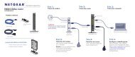
Connecting <strong>the</strong> <strong>CG814M</strong> Gateway<br />
Be<strong>for</strong>e using your modem, you need to do <strong>the</strong> following:<br />
• Connect to your computer, using ei<strong>the</strong>r E<strong>the</strong>rnet, USB or wireless (see page 2-6).<br />
• Connect <strong>the</strong> line from your cable service provider to <strong>the</strong> cable port of <strong>the</strong> gateway (see page<br />
2-7).<br />
• Connect <strong>the</strong> power adapter (see page 2-8).<br />
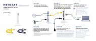
A typical installation is shown in Figure 2-1, below<br />
Connecting to Your Computer<br />
Figure 2-1: Typical installation using E<strong>the</strong>rnet.<br />
Your computer will attach to ei<strong>the</strong>r <strong>the</strong> E<strong>the</strong>rnet, USB or wireless ports on <strong>the</strong> <strong>CG814M</strong> Gateway.<br />
Connecting <strong>the</strong> Gateway to <strong>the</strong> Internet 2-5
<strong>Reference</strong> <strong>Manual</strong> <strong>for</strong> <strong>the</strong> <strong>Model</strong> <strong>CG814M</strong> <strong>Wireless</strong> <strong>Cable</strong> Modem Gateway<br />
E<strong>the</strong>rnet<br />
To connect your computer to <strong>the</strong> modem via E<strong>the</strong>rnet:<br />
1. Locate <strong>the</strong> Category 5 E<strong>the</strong>rnet cable which came with your modem.<br />
2. Connect your computer to <strong>the</strong> modem using <strong>the</strong> E<strong>the</strong>rnet cable.:<br />
USB<br />
Note: Note: The <strong>CG814M</strong> Gateway incorporates Auto Uplink TM technology. Each<br />
LOCAL E<strong>the</strong>rnet port will automatically sense whe<strong>the</strong>r <strong>the</strong> cable plugged into <strong>the</strong> port<br />
should have a 'normal' connection (e.g. connecting to a PC) or an 'uplink' connection<br />
(e.g. connecting to a switch or hub). That port will <strong>the</strong>n configure itself to <strong>the</strong> correct<br />
configuration. This feature also eliminates <strong>the</strong> need to worry about crossover cables, as<br />
Auto Uplink will accommodate ei<strong>the</strong>r type of cable to make <strong>the</strong> right connection.<br />
To connect your computer to <strong>the</strong> modem via USB involves installing <strong>the</strong> USB driver:<br />
Note: The USB connection option is only available <strong>for</strong> Windows PCs. Also, Windows<br />
95 does not support USB without special operating system upgrades and patches.<br />
1. Install <strong>the</strong> USB driver<br />
a. Insert <strong>the</strong> CD which came with your modem into <strong>the</strong> CD drive of your computer.<br />
a. Connect <strong>the</strong> USB cable to your modem and plug in <strong>the</strong> AC power <strong>for</strong> <strong>the</strong> modem.<br />
b. Use <strong>the</strong> USB cable to connect your computer to <strong>the</strong> modem.<br />
2-6 Connecting <strong>the</strong> Gateway to <strong>the</strong> Internet
<strong>Reference</strong> <strong>Manual</strong> <strong>for</strong> <strong>the</strong> <strong>Model</strong> <strong>CG814M</strong> <strong>Wireless</strong> <strong>Cable</strong> Modem Gateway<br />
The found new hardware Windows installation wizard will prompt you <strong>for</strong> <strong>the</strong> drivers.<br />
Browse to <strong>the</strong> CD and install <strong>the</strong> USB driver by clicking through <strong>the</strong> Windows wizard prompts.<br />
<strong>Wireless</strong><br />
Detailed instructions on configuring your wireless devices <strong>for</strong> TCP/IP networking are provided in<br />
<strong>the</strong> next chapter. However, if you already have a functioning wireless network and you wish to use<br />
a wireless PC to initially configure <strong>the</strong> router, you will need to change <strong>the</strong> settings of that PC to<br />
match <strong>the</strong> default settings of <strong>the</strong> router:<br />
• The SSID should be <strong>Wireless</strong> (note <strong>the</strong> capitalization).<br />
• The Channel should be set to 6.<br />
• WEP encryption is disabled.<br />
Connecting to your <strong>Cable</strong> Service Provider<br />
Using a coaxial cable provided by your cable service provider, connect <strong>the</strong> coaxial cable jack on<br />
you wall to <strong>the</strong> cable connector on <strong>the</strong> gateway.<br />
The <strong>Cable</strong> Link LED will be solid green when your gateway has synchronized with <strong>the</strong> cable<br />
headend.<br />
Connecting <strong>the</strong> Gateway to <strong>the</strong> Internet 2-7
<strong>Reference</strong> <strong>Manual</strong> <strong>for</strong> <strong>the</strong> <strong>Model</strong> <strong>CG814M</strong> <strong>Wireless</strong> <strong>Cable</strong> Modem Gateway<br />
Connecting <strong>the</strong> Power Adapter<br />
To connect <strong>the</strong> power adapter to <strong>the</strong> gateway:<br />
1. Plug <strong>the</strong> connector of <strong>the</strong> power adapter into outlet on <strong>the</strong> rear panel of <strong>the</strong> modem.<br />
2. Plug <strong>the</strong> o<strong>the</strong>r end of <strong>the</strong> adapter into an AC power outlet.<br />
3. Verify that <strong>the</strong> PWR LED on <strong>the</strong> modem is lit.<br />
After applying power to <strong>the</strong> gateway, complete <strong>the</strong> following steps to verify that power is correctly<br />
applied:<br />
1. When power is first applied, verify that <strong>the</strong> Power LED comes on.<br />
All <strong>the</strong> numbered LAN LEDs will be briefly tested.<br />
2. After approximately 10 seconds, verify that <strong>the</strong> local E<strong>the</strong>rnet or USB port LED is lit <strong>for</strong> <strong>the</strong><br />
port that is connected to your computer.<br />
If a port’s LED is lit, a link has been established to <strong>the</strong> connected device. If a local E<strong>the</strong>rnet port is<br />
connected to a 100 Mbps device, verify that <strong>the</strong> port’s LED is green. If <strong>the</strong> port is 10 Mbps, <strong>the</strong><br />
LED should be yellow.<br />
Log in to <strong>the</strong> Gateway<br />
Note: To connect to <strong>the</strong> gateway, your computer needs to be configured to obtain an IP<br />
address automatically via DHCP. Please refer to Appendix C, "Preparing Your Network"<br />
<strong>for</strong> instructions on how to do this.<br />
1. Turn on <strong>the</strong> gateway.<br />
2. Now, turn on your computer.<br />
Note: If you usually run software to log in to your Internet connection, do not run that<br />
software.<br />
2-8 Connecting <strong>the</strong> Gateway to <strong>the</strong> Internet
<strong>Reference</strong> <strong>Manual</strong> <strong>for</strong> <strong>the</strong> <strong>Model</strong> <strong>CG814M</strong> <strong>Wireless</strong> <strong>Cable</strong> Modem Gateway<br />
Now that <strong>the</strong> gateway, and <strong>the</strong> computer are turned on, verify <strong>the</strong> following:<br />
• When power on <strong>the</strong> gateway was first turned on, <strong>the</strong> PWR light went on, <strong>the</strong> numbered<br />
LAN LEDs turned on <strong>for</strong> a few seconds.<br />
• The gateway’s LOCAL LINK/ACT lights are lit <strong>for</strong> any computers that are connected to<br />
it.<br />
• The gateway’s <strong>Cable</strong> Link LED is lit, indicating a link has been established to <strong>the</strong> cable<br />
service provider.<br />
3. Next, use a browser like Internet Explorer or Netscape to log in to <strong>the</strong> gateway at its default<br />
address of http://192.168.0.1.<br />
Figure 2-2: Log in to <strong>the</strong> gateway<br />
A login window opens as shown in Figure 2-3 below:<br />
Figure 2-3: Login window<br />
Connecting <strong>the</strong> Gateway to <strong>the</strong> Internet 2-9
<strong>Reference</strong> <strong>Manual</strong> <strong>for</strong> <strong>the</strong> <strong>Model</strong> <strong>CG814M</strong> <strong>Wireless</strong> <strong>Cable</strong> Modem Gateway<br />
For security reasons, <strong>the</strong> gateway has its own user name and password. When prompted, enter<br />
admin <strong>for</strong> <strong>the</strong> gateway User Name and password <strong>for</strong> <strong>the</strong> gateway Password, both in lower case<br />
letters..<br />
Note: The user name and password are not <strong>the</strong> same as any user name or password you<br />
may use to log in to your Internet connection.<br />
4. Connect to <strong>the</strong> Internet<br />
Figure 2-4: Connection page.<br />
You are now connected to <strong>the</strong> gateway’s Connection page, shown in Figure 2-4. This page<br />
provides detailed in<strong>for</strong>mation about your cable connection.<br />
Note: If you were unable to connect to <strong>the</strong> gateway, please refer to “Basic Functions” on<br />
page 6-1.<br />
2-10 Connecting <strong>the</strong> Gateway to <strong>the</strong> Internet
<strong>Reference</strong> <strong>Manual</strong> <strong>for</strong> <strong>the</strong> <strong>Model</strong> <strong>CG814M</strong> <strong>Wireless</strong> <strong>Cable</strong> Modem Gateway<br />
Connecting <strong>the</strong> <strong>CG814M</strong> Gateway to <strong>the</strong> Internet<br />
The gateway is now properly attached to your network. You are ready to configure your gateway<br />
to connect to <strong>the</strong> Internet. To continue installation, click on <strong>the</strong> Basic Settings menu, shown in<br />
Figure 2-5..<br />
Figure 2-5: Browser-based configuration Basic Settings menu<br />
Unless your ISP assigns your configuration automatically via DHCP, you will need <strong>the</strong><br />
configuration parameters from your ISP you recorded in “Record Your Internet Connection<br />
In<strong>for</strong>mation” on page 2-4.<br />
Configuration<br />
1. Your current WAN IP address is shown on this page.<br />
Connecting <strong>the</strong> Gateway to <strong>the</strong> Internet 2-11
<strong>Reference</strong> <strong>Manual</strong> <strong>for</strong> <strong>the</strong> <strong>Model</strong> <strong>CG814M</strong> <strong>Wireless</strong> <strong>Cable</strong> Modem Gateway<br />
If you have set your configuration <strong>for</strong> Dynamic IP, below, <strong>the</strong>n an IP address shown here is an<br />
indication that you have successfully received an IP address from your service provider.<br />
If you have set your configuration to Static IP, below, <strong>the</strong>n <strong>the</strong> IP address you entered will be<br />
shown here.<br />
For Dynamic IP, <strong>the</strong> Duration and time of Expiration of <strong>the</strong> IP address are shown. The IP<br />
address is renewed automatically using DHCP.<br />
2. Enter your Host Name and Domain Name.<br />
These parameters may be necessary to access your ISP’s services such as mail or news servers.<br />
3. Select Dynamic or Static IP Address:<br />
If your service provider assigns your IP address automatically through DHCP, select<br />
“Dynamic IP”. If your service provider has assigned you a permanent, fixed (static) IP address<br />
<strong>for</strong> your PC, select “Static IP”.<br />
If you select Static IP, enter <strong>the</strong> IP address that your ISP assigned. Also enter <strong>the</strong> Static IP<br />
Mask (also known as netmask), Gateway IP address and Domain Name Server (DNS)<br />
Addresss.<br />
The Gateway is <strong>the</strong> ISP’s router to which your gateway will connect.<br />
A DNS server is a host on <strong>the</strong> Internet that translates Internet names (such as<br />
www.<strong>netgear</strong>.com) to numeric IP addresses. Typically your ISP transfers <strong>the</strong> IP address of<br />
one or two DNS servers to your gateway during login. If <strong>the</strong> ISP does not transfer an<br />
address, you must obtain it from <strong>the</strong> ISP and enter it manually here. If you enter an address<br />
here, you should reboot your PCs after configuring <strong>the</strong> gateway.<br />
4. <strong>Cable</strong> MAC Address:<br />
Device MAC Address<br />
This section indicates <strong>the</strong> <strong>Cable</strong> and Device MAC Address settings of your gateway. If you<br />
have existing cable internet service and are replacing your cable modem you may need to<br />
notify your cable service provider of <strong>the</strong> <strong>Cable</strong> MAC Address and/or Device MAC Address of<br />
your gateway in order to obtain service. The <strong>CG814M</strong> Gateway appears to your service<br />
provider to be a cable modem with a single PC connected to it. The <strong>Cable</strong> Address is <strong>the</strong><br />
equivalent of <strong>the</strong> cable modem. The Device Address is <strong>the</strong> equivalent of <strong>the</strong> PC behind <strong>the</strong><br />
cable modem, and can be “cloned”. Cloning allows you to specify <strong>the</strong> MAC address of <strong>the</strong><br />
packets <strong>the</strong> gateway sends to <strong>the</strong> internet. If you clone <strong>the</strong> MAC Address of your PC you will<br />
not have to register <strong>the</strong> Device Address of your gateway.<br />
To change <strong>the</strong> Device MAC Address that is used to send traffic to <strong>the</strong> internet, enter <strong>the</strong> MAC<br />
address you would like to use in <strong>the</strong> “Cloned MAC Address” field and check <strong>the</strong> Enable box.<br />
The MAC Address that is entered by default is <strong>the</strong> MAC Address of <strong>the</strong> PC that is accessing<br />
<strong>the</strong> gateway’s web interface.<br />
2-12 Connecting <strong>the</strong> Gateway to <strong>the</strong> Internet
<strong>Reference</strong> <strong>Manual</strong> <strong>for</strong> <strong>the</strong> <strong>Model</strong> <strong>CG814M</strong> <strong>Wireless</strong> <strong>Cable</strong> Modem Gateway<br />
5. Firewall Protection:<br />
Normally firewall protection should be enabled to protect your network from attacks from <strong>the</strong><br />
internet. Removing <strong>the</strong> check from <strong>the</strong> “Firewall Protection” box disables your firewall.<br />
6. Click Apply to save your settings.<br />
Connecting <strong>the</strong> Gateway to <strong>the</strong> Internet 2-13
<strong>Reference</strong> <strong>Manual</strong> <strong>for</strong> <strong>the</strong> <strong>Model</strong> <strong>CG814M</strong> <strong>Wireless</strong> <strong>Cable</strong> Modem Gateway<br />
2-14 Connecting <strong>the</strong> Gateway to <strong>the</strong> Internet
<strong>Reference</strong> <strong>Manual</strong> <strong>for</strong> <strong>the</strong> <strong>Model</strong> <strong>CG814M</strong> <strong>Wireless</strong> <strong>Cable</strong> Modem Gateway<br />
Chapter 3<br />
<strong>Wireless</strong> Configuration<br />
This chapter describes how to configure <strong>the</strong> wireless features of your <strong>CG814M</strong> <strong>Wireless</strong> <strong>Cable</strong><br />
Modem Gateway.<br />
Considerations For A <strong>Wireless</strong> Network<br />
In planning your wireless network, you should consider <strong>the</strong> level of security required. You should<br />
also select <strong>the</strong> physical placement of your gateway in order to maximize <strong>the</strong> network speed. For<br />
fur<strong>the</strong>r in<strong>for</strong>mation on wireless networking, refer to “<strong>Wireless</strong> Networking” in Appendix B,<br />
"Networks, Routing, and Firewall Basics".”<br />
Security<br />
Note: If you are configuring <strong>the</strong> gateway from a wireless PC and you change <strong>the</strong><br />
gateway’s SSID, channel, or WEP settings, you will lose your wireless connection when<br />
you click on Apply. You must <strong>the</strong>n change <strong>the</strong> wireless settings of your PC to match <strong>the</strong><br />
gateway’s new settings.<br />
Unlike wired network data, your wireless data transmissions can extend beyond your walls and<br />
can be received by anyone with a compatible adapter. For this reason, NETGEAR strongly<br />
recommends that you make use of <strong>the</strong> security features of your wireless equipment. As a minimum<br />
security precaution, you should change <strong>the</strong> SSID setting of all devices on your network from <strong>the</strong><br />
factory setting to a unique password. Restricting access by MAC address filtering adds ano<strong>the</strong>r<br />
obstacle against unwanted hosts joining your network. To hinder a determined eavesdropper, you<br />
should enable Wired Equivalent Privacy (WEP) data encryption.<br />
<strong>Wireless</strong> Configuration 3-1
<strong>Reference</strong> <strong>Manual</strong> <strong>for</strong> <strong>the</strong> <strong>Model</strong> <strong>CG814M</strong> <strong>Wireless</strong> <strong>Cable</strong> Modem Gateway<br />
Placement and Range<br />
The operating distance or range of your wireless connection can vary significantly based on <strong>the</strong><br />
physical placement of <strong>the</strong> wireless gateway. For best results, place your gateway:<br />
• near <strong>the</strong> center of <strong>the</strong> area in which your PCs will operate,<br />
• in an elevated location such as a high shelf,<br />
• away from potential sources of interference, such as PCs, microwaves, and cordless phones,<br />
• away from large metal surfaces.<br />
<strong>Wireless</strong> Settings<br />
To configure <strong>the</strong> <strong>Wireless</strong> interface of your gateway, click on <strong>the</strong> <strong>Wireless</strong> Settings heading in <strong>the</strong><br />
Setup section of <strong>the</strong> browser interface. The <strong>Wireless</strong> Settings menu will appear, as shown in<br />
Figure 3-1:<br />
Figure 3-1: <strong>Wireless</strong> Settings menu<br />
3-2 <strong>Wireless</strong> Configuration
<strong>Wireless</strong> Settings<br />
<strong>Reference</strong> <strong>Manual</strong> <strong>for</strong> <strong>the</strong> <strong>Model</strong> <strong>CG814M</strong> <strong>Wireless</strong> <strong>Cable</strong> Modem Gateway<br />
In <strong>the</strong> <strong>Wireless</strong> Settings section are <strong>the</strong> following parameters:<br />
• Name (SSID)<br />
Enter a Service Set ID (SSID) value of up to 32 alphanumeric characters. The same SSID must<br />
be assigned to all wireless devices in your network. The default SSID is <strong>Wireless</strong>, but<br />
NETGEAR strongly recommends that you change your network’s SSID to a different value.<br />
• Channel<br />
This field determines which operating frequency will be used. It should not be necessary to<br />
change <strong>the</strong> wireless channel unless you notice interference problems with ano<strong>the</strong>r nearby<br />
access point.<br />
Restricting <strong>Wireless</strong> Access by MAC Address<br />
By default, any wireless PC that is configured with <strong>the</strong> correct SSID will be allowed access to your<br />
wireless network. For increased security, you can restrict access to <strong>the</strong> wireless network to only<br />
allow specific PCs based on <strong>the</strong>ir MAC addresses.<br />
Check <strong>the</strong> Turn Access Control On box to restrict access to you network to computers in <strong>the</strong><br />
Access Control List.<br />
To access <strong>the</strong> Access List, click <strong>the</strong> Setup Access List button shown in Figure 3-2:<br />
Figure 3-2: <strong>Wireless</strong> Access List menu<br />
<strong>Wireless</strong> Configuration 3-3
<strong>Reference</strong> <strong>Manual</strong> <strong>for</strong> <strong>the</strong> <strong>Model</strong> <strong>CG814M</strong> <strong>Wireless</strong> <strong>Cable</strong> Modem Gateway<br />
The <strong>Wireless</strong> Access window displays a list of MAC addresses that will be allowed to connect to<br />
<strong>the</strong> gateway. These PCs must also have <strong>the</strong> correct SSID and WEP settings. To restrict access<br />
based on MAC addresses:<br />
1. Click <strong>the</strong> Add button to go to <strong>the</strong> Add/Edit menu.<br />
For your convenience, this menu displays a list of currently active wireless cards and <strong>the</strong>ir<br />
MAC addresses.<br />
2. If <strong>the</strong> desired PC appears in <strong>the</strong> list, you can click on it to capture its MAC address; o<strong>the</strong>rwise,<br />
you can manually enter <strong>the</strong> MAC address of <strong>the</strong> authorized PC.<br />
The MAC address is usually printed on <strong>the</strong> wireless card.<br />
3. If no Device Name appears, you can type a descriptive name <strong>for</strong> <strong>the</strong> PC that you are adding.<br />
4. Click Add.<br />
5. When you have finished entering MAC addresses, return to <strong>the</strong> <strong>Wireless</strong> Access List menu<br />
and check <strong>the</strong> Turn Access Control On box, <strong>the</strong>n click Apply.<br />
To edit a MAC address from <strong>the</strong> table, click on it to select it, <strong>the</strong>n click <strong>the</strong> Edit or Delete button.<br />
Note: If <strong>the</strong> Turn Access Control On is enabled and <strong>the</strong> Access Control List is<br />
blank; <strong>the</strong>n all wireless PCs will be unable to connect to your wireless network.<br />
Configuring Wired Equivalent Privacy (WEP)<br />
In <strong>the</strong> <strong>Wireless</strong> Settings menu you can configure WEP data encryption from <strong>the</strong> Security<br />
Encryption (WEP) section using <strong>the</strong> following parameters:<br />
• Encryption Mode<br />
Select <strong>the</strong> WEP Encryption level:<br />
• Off - no data encryption (Open System)<br />
• 64-bit (sometimes called 40-bit) encryption<br />
• 128-bit encryption<br />
• Au<strong>the</strong>ntication Type<br />
Select <strong>the</strong> appropriate value - "Open System" or "Shared Key." Check your wireless card's<br />
documentation to see what method to use.<br />
• Keys<br />
If WEP is enabled, you can manually or automatically program <strong>the</strong> four data encryption keys.<br />
These values must be identical on all PCs and Access Points in your network.<br />
3-4 <strong>Wireless</strong> Configuration
<strong>Reference</strong> <strong>Manual</strong> <strong>for</strong> <strong>the</strong> <strong>Model</strong> <strong>CG814M</strong> <strong>Wireless</strong> <strong>Cable</strong> Modem Gateway<br />
• Automatic - Enter a word or group of printable characters in <strong>the</strong> Passphrase box and click<br />
<strong>the</strong> Generate button. The four key boxes will be automatically populated with key values.<br />
• <strong>Manual</strong> - Enter ten hexadecimal digits (any combination of 0-9, a-f, or A-F)<br />
Select which of <strong>the</strong> four keys will be active.<br />
Be sure to click Apply to save your settings in this menu.<br />
<strong>Wireless</strong> Configuration 3-5
<strong>Reference</strong> <strong>Manual</strong> <strong>for</strong> <strong>the</strong> <strong>Model</strong> <strong>CG814M</strong> <strong>Wireless</strong> <strong>Cable</strong> Modem Gateway<br />
3-6 <strong>Wireless</strong> Configuration
<strong>Reference</strong> <strong>Manual</strong> <strong>for</strong> <strong>the</strong> <strong>Model</strong> <strong>CG814M</strong> <strong>Wireless</strong> <strong>Cable</strong> Modem Gateway<br />
Chapter 4<br />
Protecting Your Network<br />
This chapter describes how to use <strong>the</strong> firewall features of <strong>the</strong> <strong>CG814M</strong> <strong>Wireless</strong> <strong>Cable</strong> Modem<br />
Gateway to protect your network.<br />
Protecting Access to Your <strong>CG814M</strong> Gateway<br />
For security reasons, <strong>the</strong> gateway has its own user name and password. Also, after a period of<br />
inactivity <strong>for</strong> a set length of time, <strong>the</strong> administrator login will automatically disconnect. When<br />
prompted, enter admin <strong>for</strong> <strong>the</strong> gateway User Name and password <strong>for</strong> <strong>the</strong> gateway Password.<br />
You can use procedures below to change <strong>the</strong> gateway's password and <strong>the</strong> amount of time <strong>for</strong> <strong>the</strong><br />
administrator’s login timeout.<br />
Note: The user name and password are not <strong>the</strong> same as any user name or password your may use<br />
to log in to your Internet connection.<br />
NETGEAR recommends that you change this password to a more secure password. The ideal<br />
password should contain no dictionary words from any language, and should be a mixture of both<br />
upper and lower case letters, numbers, and symbols. Your password can be up to 30 characters.<br />
Changing <strong>the</strong> Built-In Password<br />
1. Log in to <strong>the</strong> gateway at its default LAN address of http://192.168.0.1 with its default User<br />
Name of admin, default password of password, or using whatever Password and LAN<br />
address you have chosen <strong>for</strong> <strong>the</strong> gateway.<br />
Figure 4-1: Log in to <strong>the</strong> gateway<br />
Protecting Your Network 4-1
<strong>Reference</strong> <strong>Manual</strong> <strong>for</strong> <strong>the</strong> <strong>Model</strong> <strong>CG814M</strong> <strong>Wireless</strong> <strong>Cable</strong> Modem Gateway<br />
2. From <strong>the</strong> Main Menu of <strong>the</strong> browser interface, under <strong>the</strong> Maintenance heading, select Set<br />
Password to bring up <strong>the</strong> menu shown in Figure 4-2.<br />
Figure 4-2: Set Password menu<br />
3. To change <strong>the</strong> password, first enter <strong>the</strong> old password, and <strong>the</strong>n enter <strong>the</strong> new password twice.<br />
4. If you would like to reset your gateway to its factory default settings select Yes <strong>for</strong> Restore<br />
Factory Defaults. This will remove all configuration in<strong>for</strong>mation you have entered.<br />
5. Click Apply to save your changes.<br />
Note: After changing <strong>the</strong> password, you will be required to log in again to continue <strong>the</strong><br />
configuration. If you have backed up <strong>the</strong> gateway settings previously, you should do a new<br />
backup so that <strong>the</strong> saved settings file includes <strong>the</strong> new password.<br />
Blocking Keywords, Sites, and Services<br />
The gateway provides a variety of options <strong>for</strong> blocking Internet based content and<br />
communications services. With its content filtering feature, <strong>the</strong> <strong>CG814M</strong> Gateway prevents<br />
objectionable content from reaching your PCs. The <strong>CG814M</strong> allows you to control access to<br />
Internet content by screening <strong>for</strong> keywords within Web addresses. It also has <strong>the</strong> capability to<br />
block access to all sites except those that are explicitely allowed. Key content filtering<br />
options include:<br />
• Blocking access from your LAN to Internet locations that contain keywords that your specify.<br />
• Blocking access to web sites that you specify as off-limits.<br />
4-2 Protecting Your Network
<strong>Reference</strong> <strong>Manual</strong> <strong>for</strong> <strong>the</strong> <strong>Model</strong> <strong>CG814M</strong> <strong>Wireless</strong> <strong>Cable</strong> Modem Gateway<br />
• Allowing access to only web sites that you specify as allowed.<br />
• Filtering of Proxy servers, Cookies, Java, ActiveX and Popup Windows<br />
The section below explains how to configure your gateway to per<strong>for</strong>m <strong>the</strong>se functions.<br />
Block Keywords and Domains<br />
The <strong>CG814M</strong> Gateway allows you to restrict access to Internet content based on functions such as<br />
web address keywords and web domains.<br />
A domain name is <strong>the</strong> name of a particular web site. For example, <strong>for</strong> <strong>the</strong> address<br />
www.NETGEAR.com, <strong>the</strong> domain name is NETGEAR.com.<br />
Log in to <strong>the</strong> gateway at its default LAN address of http://192.168.0.1 with its default User Name<br />
of admin, default password of password, or using whatever Password and LAN address you have<br />
chosen <strong>for</strong> <strong>the</strong> gateway.<br />
Protecting Your Network 4-3
<strong>Reference</strong> <strong>Manual</strong> <strong>for</strong> <strong>the</strong> <strong>Model</strong> <strong>CG814M</strong> <strong>Wireless</strong> <strong>Cable</strong> Modem Gateway<br />
1. Click on <strong>the</strong> Block Sites link of <strong>the</strong> Content Filtering menu.<br />
Figure 4-3: Block Sites menu<br />
2. To enable keyword blocking or Domain Blocking, check <strong>the</strong> appropriate Enable box.<br />
4-4 Protecting Your Network
<strong>Reference</strong> <strong>Manual</strong> <strong>for</strong> <strong>the</strong> <strong>Model</strong> <strong>CG814M</strong> <strong>Wireless</strong> <strong>Cable</strong> Modem Gateway<br />
3. Enter Keywords into <strong>the</strong> Keyword List by typing <strong>the</strong>n in <strong>the</strong> Add Keyword box, <strong>the</strong>n, click<br />
Add Keyword.<br />
Some examples of Keyword applications follow:<br />
• If <strong>the</strong> keyword “XXX” is specified, <strong>the</strong> URL is<br />
blocked.<br />
• If <strong>the</strong> keyword “.com” is specified, only websites with o<strong>the</strong>r domain suffixes (such as .edu<br />
or .gov) can be viewed.<br />
• Enter <strong>the</strong> keyword “.” to block all Internet browsing access.<br />
Up to 8 entries are supported in <strong>the</strong> Keyword list.<br />
4. Enter Domains into <strong>the</strong> Domain List by typing <strong>the</strong>n in <strong>the</strong> Add Domain box, <strong>the</strong>n, click Add<br />
Domain.<br />
If <strong>the</strong> domain “badstuff.com” is specified, <strong>the</strong> URL is<br />
blocked, along with all o<strong>the</strong>r urls in <strong>the</strong> badstuff.com site.<br />
Up to 8 entries are supported in <strong>the</strong> Keyword list.<br />
5. To block access to <strong>the</strong> domains in <strong>the</strong> Domain List, select Deny Domains.<br />
To allow access to only <strong>the</strong> domains in <strong>the</strong> Domain List, select Allow Domains. If <strong>the</strong> domain<br />
“goodstuff.com” is specified, you will be able to access only sites on <strong>the</strong> goodstuff site.<br />
6. To delete a keyword or domain, select it from <strong>the</strong> list, click Remove Keyword or Remove<br />
Domain.<br />
7. Configure <strong>the</strong> times when access rules apply in <strong>the</strong> Schedule section.<br />
8. Click Apply to save your settings.<br />
Blocking Services<br />
The <strong>CG814M</strong> Gateway allows you to block access to specific traffic such as proxies, cookies, Java<br />
Applets, ActiveX and popup windows.<br />
To enable filtering of services, from <strong>the</strong> Content Filtering section of <strong>the</strong> Main Menu, select<br />
Services. Check <strong>the</strong> Enable box <strong>for</strong> whichever service you would like to block and click Apply.<br />
Proxy<br />
The proxy filter will prevent PCs from using a proxy server to surf <strong>the</strong> web. A proxy server could<br />
be used to bypass parental control features because <strong>the</strong> port number <strong>for</strong> a proxy is usually 8080.<br />
Protecting Your Network 4-5
<strong>Reference</strong> <strong>Manual</strong> <strong>for</strong> <strong>the</strong> <strong>Model</strong> <strong>CG814M</strong> <strong>Wireless</strong> <strong>Cable</strong> Modem Gateway<br />
Most web surfing is done on port 80. The parental control feature monitors port 80 so proxy based<br />
web surfing would not be inspected by <strong>the</strong> parental controls. The proxy filter should be used if<br />
parental controls are being used.<br />
Cookies<br />
A cookie is a text file saved by your web browser which is sent to a particular web servier every<br />
time you visit <strong>the</strong> site. Cookies are used to identify you to <strong>the</strong> web server automatically.<br />
Java Applets<br />
Java Applets are programs that run from within ano<strong>the</strong>r application, such as a web browser.<br />
ActiveX<br />
An ActiveX control is a Microsoft Windows program that can be downloaded from a web page<br />
and automatically executed by your web browser on your PC.<br />
Popup Windows<br />
Many internet sites open additional browser windows, called popups. They are often used <strong>for</strong><br />
advertisments. The <strong>CG814M</strong> can filter out many of <strong>the</strong>se popup windows.<br />
Port Blocking<br />
Firewall rules are used to block or allow specific traffic passing through from one side to <strong>the</strong> o<strong>the</strong>r.<br />
Inbound rules (WAN to LAN) restrict access by outsiders to private resources, selectively allowing<br />
only specific outside users to access specific resources. Instructions <strong>for</strong> setting up inbound rules<br />
can be found in “Port Forwarding“ on page -7. Outbound rules (LAN to WAN) determine what<br />
outside resources local users can have access to. This section describes how to set up outbound<br />
rules.<br />
A firewall has two default rules, one <strong>for</strong> inbound traffic and one <strong>for</strong> outbound. The default rules of<br />
<strong>the</strong> <strong>CG814M</strong> Gateway are:<br />
• Inbound: Block all access from outside except responses to requests from <strong>the</strong> LAN side.<br />
• Outbound: Allow all access from <strong>the</strong> LAN side to <strong>the</strong> outside.<br />
You may define additional rules that will specify exceptions to <strong>the</strong> default rules. By adding custom<br />
rules, you can block or allow access based on <strong>the</strong> service or application, source or destination IP<br />
addresses, and time of day. You can also choose to log traffic that matches or does not match <strong>the</strong><br />
4-6 Protecting Your Network
ule you have defined.<br />
<strong>Reference</strong> <strong>Manual</strong> <strong>for</strong> <strong>the</strong> <strong>Model</strong> <strong>CG814M</strong> <strong>Wireless</strong> <strong>Cable</strong> Modem Gateway<br />
To configure outbound rules on <strong>the</strong> <strong>CG814M</strong> Gateway, click <strong>the</strong> Port Blocking link on <strong>the</strong><br />
Advanced section of <strong>the</strong> main menu.<br />
Figure 4-4: Port Blocking menu<br />
• To block outbound traffic, select <strong>the</strong> service you would like to block from <strong>the</strong> drop-down<br />
list of predefined services. Click Add.<br />
• If <strong>the</strong> service you would like to block is not in <strong>the</strong> predefined list, you can add a custom<br />
service. Enter <strong>the</strong> range of ports you would like to block and select whe<strong>the</strong>r <strong>the</strong> ports are<br />
TCP, UDP or Both. Click Add.<br />
• To delete an existing rule, select its button on <strong>the</strong> left side of <strong>the</strong> table and click Delete.<br />
Port Forwarding<br />
Because <strong>the</strong> <strong>CG814M</strong> Gateway uses Network Address Translation (NAT), your network presents<br />
Protecting Your Network 4-7
<strong>Reference</strong> <strong>Manual</strong> <strong>for</strong> <strong>the</strong> <strong>Model</strong> <strong>CG814M</strong> <strong>Wireless</strong> <strong>Cable</strong> Modem Gateway<br />
only one IP address to <strong>the</strong> Internet, and outside users cannot directly address any of your local<br />
computers. However, by defining an inbound rule you can make a local server (<strong>for</strong> example, a web<br />
server or game server) visible and available to <strong>the</strong> Internet. The rule tells <strong>the</strong> gateway to direct<br />
inbound traffic <strong>for</strong> a particular service to one local server based on <strong>the</strong> destination port number.<br />
This is also known as Port Forwarding.<br />
Note: Some residential broadband ISP accounts do not allow you to run any server<br />
processes (such as a Web or FTP server) from your location. Your ISP may periodically<br />
check <strong>for</strong> servers and may suspend your account if it discovers any active services at<br />
your location. If you are unsure, refer to <strong>the</strong> Acceptable Use Policy of your ISP.<br />
Remember that allowing inbound services opens holes in your firewall. Only enable those ports<br />
that are necessary <strong>for</strong> your network. Following are two application examples of inbound rules:<br />
To configure inbound rules on <strong>the</strong> <strong>CG814M</strong> Gateway, click <strong>the</strong> Port Forwarding link on <strong>the</strong><br />
Advanced section of <strong>the</strong> main menu..<br />
• To <strong>for</strong>ward inbound traffic:<br />
Figure 4-5: Port Forwarding menu<br />
4-8 Protecting Your Network
<strong>Reference</strong> <strong>Manual</strong> <strong>for</strong> <strong>the</strong> <strong>Model</strong> <strong>CG814M</strong> <strong>Wireless</strong> <strong>Cable</strong> Modem Gateway<br />
1. Select <strong>the</strong> service you would like to <strong>for</strong>ward from <strong>the</strong> drop-down list of predefined<br />
services.<br />
If <strong>the</strong> service you would like to <strong>for</strong>ward is not in <strong>the</strong> predefined list, you can add a<br />
custom service. Enter <strong>the</strong> range of ports you would like to <strong>for</strong>ward and select whe<strong>the</strong>r<br />
<strong>the</strong> ports are TCP, UDP or Both.<br />
2. Enter <strong>the</strong> IP address of <strong>the</strong> computer on your network to which you would like to<br />
direct <strong>the</strong> inbound traffic<br />
3. Click Add.<br />
4. To access <strong>the</strong> local computer from <strong>the</strong> Internet, you must use <strong>the</strong> WAN address of your<br />
gateway, which can be found on <strong>the</strong> Basic Settings page.<br />
• To delete an existing rule, select its button on <strong>the</strong> left side of <strong>the</strong> table and click Delete.<br />
Considerations <strong>for</strong> Port Forwarding<br />
If your external IP address is assigned dynamically by your ISP, <strong>the</strong> IP address may change<br />
periodically as <strong>the</strong> DHCP lease expires. Consider using <strong>the</strong> Dynamic DNS feature in <strong>the</strong> Advanced<br />
menus so that external users can always find your network.<br />
• If <strong>the</strong> IP address of <strong>the</strong> local server PC is assigned by DHCP, it may change when <strong>the</strong> PC is<br />
rebooted. To avoid this, you can assign a static IP address to your server outside <strong>the</strong> range that<br />
is assigned by DHCP, but in <strong>the</strong> same subnet as <strong>the</strong> rest of your LAN. By default, <strong>the</strong> IP<br />
addresses in <strong>the</strong> range of 192.168.0.2 through 192.168.0.9 are reserved <strong>for</strong> this.<br />
• Local PCs must access <strong>the</strong> local server using <strong>the</strong> PCs’ local LAN address (192.168.0.XXX, by<br />
default). Attempts by local PCs to access <strong>the</strong> server using <strong>the</strong> external WAN IP address will<br />
fail.<br />
Port Triggering<br />
Port Triggering is an advanced feature that allows you to dynamically open inbound ports based on<br />
outbound traffic on different ports. This is an advanced feature that can be used <strong>for</strong> gaming and<br />
o<strong>the</strong>r internet applications.<br />
Port Forwarding can typically be used to enable similar functionality, but it is static and has some<br />
limitations. Ports will be open to traffic from <strong>the</strong> internet until <strong>the</strong> port <strong>for</strong>warding rule is removed.<br />
Additionally, port <strong>for</strong>warding does not work well <strong>for</strong> some applications when your WAN IP<br />
address is assigned by DHCP, and is changed frequently. Port Triggering opens in incoming port<br />
temporarily and can does not require <strong>the</strong> server on <strong>the</strong> internet to track your IP address if it is<br />
Protecting Your Network 4-9
<strong>Reference</strong> <strong>Manual</strong> <strong>for</strong> <strong>the</strong> <strong>Model</strong> <strong>CG814M</strong> <strong>Wireless</strong> <strong>Cable</strong> Modem Gateway<br />
changed.<br />
Port Triggering monitors outbound traffic. When <strong>the</strong> gateway detects traffic on <strong>the</strong> specified<br />
outbound port, it remembers <strong>the</strong> IP address of <strong>the</strong> computer that sent <strong>the</strong> data and “triggers” <strong>the</strong><br />
incoming port. Incoming traffic on <strong>the</strong> triggered port is <strong>the</strong>n <strong>for</strong>warded to <strong>the</strong> triggering computer.<br />
An example of Port Triggering <strong>for</strong> Internet Relay Chat (IRC) is shown in Figure 4-6. When you<br />
connect to an IRC server, <strong>the</strong> server tries to connect back on port 113 to do an Ident lookup. Unless<br />
you have configured Port Forwarding to open port 113, <strong>the</strong> traffic will be blocked. In this example,<br />
<strong>the</strong> initial login to <strong>the</strong> server in <strong>the</strong> range of ports 6660 to 6670 will be detected. This will trigger<br />
<strong>the</strong> gateway to temporarily <strong>for</strong>ward port 113 to <strong>the</strong> PC that initiated <strong>the</strong> login.l<br />
To configure Port Triggering:<br />
Figure 4-6: Port Triggering menu, with IRC example.<br />
4-10 Protecting Your Network
<strong>Reference</strong> <strong>Manual</strong> <strong>for</strong> <strong>the</strong> <strong>Model</strong> <strong>CG814M</strong> <strong>Wireless</strong> <strong>Cable</strong> Modem Gateway<br />
1. In <strong>the</strong> Trigger Range, enter <strong>the</strong> outbound ports that will be monitored <strong>for</strong> activity. This will be<br />
<strong>the</strong> “trigger”.<br />
2. In <strong>the</strong> Targe Range, enter <strong>the</strong> inbound ports that should be <strong>for</strong>warded when <strong>the</strong> trigger occurs.<br />
3. Select <strong>the</strong> appropriate protocol: TCP, UDP or Both.<br />
4. Check <strong>the</strong> Enable box<br />
5. Click Apply<br />
To clear a Port Triggering rule, you can ei<strong>the</strong>r remove <strong>the</strong> check from <strong>the</strong> Enable box, to<br />
temporarily disable <strong>the</strong> rule, or you can select <strong>the</strong> rule and click Delete.<br />
Setting Up A Default DMZ Host<br />
The Default DMZ Server feature is helpful when using some online games and videoconferencing<br />
applications that are incompatible with NAT. The gateway is programmed to recognize some of<br />
<strong>the</strong>se applications and to work properly with <strong>the</strong>m, but <strong>the</strong>re are o<strong>the</strong>r applications that may not<br />
function well. In some cases, one local PC can run <strong>the</strong> application properly if that PC’s IP address<br />
is entered as <strong>the</strong> Default DMZ Host.<br />
Note: For security, you should avoid using <strong>the</strong> Default DMZ Server feature. When a<br />
computer is designated as <strong>the</strong> Default DMZ Server, it loses much of <strong>the</strong> protection of <strong>the</strong><br />
firewall, and is exposed to many exploits from <strong>the</strong> Internet. If compromised, <strong>the</strong><br />
computer can be used to attack your network.<br />
Incoming traffic from <strong>the</strong> Internet is normally discarded by <strong>the</strong> gateway unless <strong>the</strong> traffic is a<br />
response to one of your local computers or a service that you have configured in <strong>the</strong> Port<br />
Forwarding or Port Triggering menu. Instead of discarding this traffic, you can have it <strong>for</strong>warded<br />
to one computer on your network. This computer is called <strong>the</strong> Default DMZ Host.<br />
To assign a computer or server to be a DMZ Host, from <strong>the</strong> Main Menu, under Advanced, select<br />
DMZ Host. Enter <strong>the</strong> IP address of <strong>the</strong> computer you would like to assign as a DMZ Host and click<br />
Apply. To disable <strong>the</strong> DMZ Host, enter “0” and click Apply.<br />
Respond to Ping on Internet WAN Port<br />
If you want <strong>the</strong> gateway to respond to a 'ping' from <strong>the</strong> Internet, click <strong>the</strong> ‘Respond to Ping on<br />
Protecting Your Network 4-11
<strong>Reference</strong> <strong>Manual</strong> <strong>for</strong> <strong>the</strong> <strong>Model</strong> <strong>CG814M</strong> <strong>Wireless</strong> <strong>Cable</strong> Modem Gateway<br />
WAN Port’ check box. This should only be used as a diagnostic tool, since it allows your gateway<br />
to be discovered. Don't check this box unless you have a specific reason to do so.<br />
4-12 Protecting Your Network
<strong>Reference</strong> <strong>Manual</strong> <strong>for</strong> <strong>the</strong> <strong>Model</strong> <strong>CG814M</strong> <strong>Wireless</strong> <strong>Cable</strong> Modem Gateway<br />
Chapter 5<br />
Managing Your Network<br />
This chapter describes how to per<strong>for</strong>m network management tasks with your <strong>CG814M</strong> <strong>Wireless</strong><br />
<strong>Cable</strong> Modem Gateway.<br />
Network Status In<strong>for</strong>mation<br />
The <strong>CG814M</strong> provides a variety of status and usage in<strong>for</strong>mation which is discussed below.<br />
Managing Your Network 5-1
<strong>Reference</strong> <strong>Manual</strong> <strong>for</strong> <strong>the</strong> <strong>Model</strong> <strong>CG814M</strong> <strong>Wireless</strong> <strong>Cable</strong> Modem Gateway<br />
Viewing Gateway Status<br />
From <strong>the</strong> Main Menu, under Maintenance, select Gateway Status to view <strong>the</strong> screen in Figure 5-1.<br />
This screen shows <strong>the</strong> following parameters:<br />
Figure 5-1: Gateway Status screen<br />
Table 5-1. Menu 3.2 - Router Status Fields<br />
Field Description<br />
In<strong>for</strong>mation<br />
Standard Specification<br />
Compliant<br />
The specification to which <strong>the</strong> gateway’s cable interface is compatible.<br />
Hardware Version The hardware version of <strong>the</strong> gateway.<br />
Software Version The software version of <strong>the</strong> gateway.<br />
<strong>Cable</strong> Modem MAC Address The MAC address being used by <strong>the</strong> <strong>Cable</strong> Modem port of <strong>the</strong> gateway.<br />
This MAC address may need to be registered with your <strong>Cable</strong> Service<br />
Provider.<br />
<strong>Cable</strong> Modem Serial<br />
Number<br />
The serial number of <strong>the</strong> gateway hardware.<br />
5-2 Managing Your Network
<strong>Reference</strong> <strong>Manual</strong> <strong>for</strong> <strong>the</strong> <strong>Model</strong> <strong>CG814M</strong> <strong>Wireless</strong> <strong>Cable</strong> Modem Gateway<br />
Table 5-1. Menu 3.2 - Router Status Fields<br />
Field Description<br />
Status<br />
CM Certificate If <strong>the</strong> <strong>Cable</strong> Modem certificate is Installed, it is possible <strong>for</strong> <strong>the</strong> service<br />
provider to upgrade your Data Over <strong>Cable</strong> service securely.<br />
System Up Time This is <strong>the</strong> time since <strong>the</strong> gateway has registered with your cable service<br />
provider.<br />
Network Access This field will change to Allowed when <strong>the</strong> registration with your cable<br />
service provider is complete.<br />
<strong>Cable</strong> Modem IP Address The IP address of you gateway, as seen from <strong>the</strong> Internet.<br />
Managing Your Network 5-3
<strong>Reference</strong> <strong>Manual</strong> <strong>for</strong> <strong>the</strong> <strong>Model</strong> <strong>CG814M</strong> <strong>Wireless</strong> <strong>Cable</strong> Modem Gateway<br />
Connection Status<br />
From <strong>the</strong> Main Menu, under Maintenance, select Connection to view <strong>the</strong> screen in Figure 5-2.<br />
Figure 5-2: Connection screen<br />
This screen shows detailed in<strong>for</strong>mation about <strong>the</strong> status of <strong>the</strong> connection to your cable service<br />
provider that can be used <strong>for</strong> troubleshooting. The gateway goes through <strong>the</strong> following steps to be<br />
provisioned<br />
1. Acquire and lock Downstream Channel<br />
2. Acquire upstream parameters and range.<br />
3. Lock Upstream Channel<br />
4. Acquire IP Address through DHCP<br />
5-4 Managing Your Network
Current System Time<br />
<strong>Reference</strong> <strong>Manual</strong> <strong>for</strong> <strong>the</strong> <strong>Model</strong> <strong>CG814M</strong> <strong>Wireless</strong> <strong>Cable</strong> Modem Gateway<br />
The date and time is acquired from your cable service provider as part of <strong>the</strong> registration<br />
procedure.<br />
Configuring LAN IP Settings<br />
The LAN IP Setup menu allows configuration of LAN IP services such as <strong>the</strong> IP address of <strong>the</strong><br />
gateway and DHCP. These features can be found under <strong>the</strong> Advanced heading in <strong>the</strong> Main Menu<br />
in <strong>the</strong> LAN IP menu.<br />
LAN IP Setup<br />
The gateway is shipped preconfigured to use private IP addresses on <strong>the</strong> LAN side, and to act as a<br />
DHCP server. The gateway’s default LAN IP configuration is:<br />
• LAN IP addresses—192.168.0.1<br />
• Subnet mask—255.255.255.0<br />
These addresses are part of <strong>the</strong> IETF-designated private address range <strong>for</strong> use in private networks,<br />
and should be suitable in most applications. If your network has a requirement to use a different IP<br />
addressing scheme, you can make those changes in this menu.<br />
The LAN TCP/IP Setup parameters are:<br />
• LAN IP Address<br />
This is <strong>the</strong> IP address of <strong>the</strong> gateway.<br />
• Subnet Mask<br />
This is <strong>the</strong> LAN Subnet Mask of <strong>the</strong> gateway. Combined with <strong>the</strong> IP address, <strong>the</strong> Subnet Mask<br />
allows a device to know which o<strong>the</strong>r addresses are local to it, and which must be reached<br />
through a gateway or router.<br />
Note: If you change <strong>the</strong> LAN IP address of <strong>the</strong> gateway while connected through <strong>the</strong><br />
browser, you will be disconnected. You must <strong>the</strong>n open a new connection to <strong>the</strong> new IP<br />
address and log in again.<br />
Managing Your Network 5-5
<strong>Reference</strong> <strong>Manual</strong> <strong>for</strong> <strong>the</strong> <strong>Model</strong> <strong>CG814M</strong> <strong>Wireless</strong> <strong>Cable</strong> Modem Gateway<br />
DHCP<br />
By default, <strong>the</strong> gateway will function as a DHCP (Dynamic Host Configuration Protocol) server,<br />
allowing it to assign IP, DNS server, and default gateway addresses to all computers connected to<br />
<strong>the</strong> router's LAN. The assigned default gateway address is <strong>the</strong> LAN address of <strong>the</strong> gateway. IP<br />
addresses will be assigned to <strong>the</strong> attached PCs from a pool of addresses specified in this menu.<br />
Each pool address is tested be<strong>for</strong>e it is assigned to avoid duplicate addresses on <strong>the</strong> LAN.<br />
For most applications, <strong>the</strong> default DHCP and TCP/IP settings of <strong>the</strong> gateway are satisfactory. See<br />
“IP Configuration by DHCP” on page B-10” <strong>for</strong> an explanation of DHCP and in<strong>for</strong>mation about<br />
how to assign IP addresses <strong>for</strong> your network.<br />
Use router as DHCP server<br />
If ano<strong>the</strong>r device on your network will be <strong>the</strong> DHCP server, or if you will manually configure <strong>the</strong><br />
network settings of all of your computers, select NO <strong>for</strong> <strong>the</strong> DHCP Server, o<strong>the</strong>rwise leave Yes<br />
selected.<br />
Specify <strong>the</strong> pool of IP addresses to be assigned by setting <strong>the</strong> Starting IP Address and Ending IP<br />
Address. These addresses should be part of <strong>the</strong> same IP address subnet as <strong>the</strong> gateway’s LAN IP<br />
address. Using <strong>the</strong> default addressing scheme, you should define a range between 192.168.0.10<br />
and 192.168.0.253. The range of IP addresses between 192.168.0.2 and 192.168.0.9 can be used<br />
<strong>for</strong> devices with fixed addresses.<br />
The gateway will deliver <strong>the</strong> following parameters to any LAN device that requests DHCP:<br />
• An IP Address from <strong>the</strong> range you have defined<br />
• Subnet Mask<br />
• Gateway IP Address is <strong>the</strong> gateway’s LAN IP address<br />
• Primary DNS Server, if you entered a Primary DNS address in <strong>the</strong> Basic Settings menu;<br />
o<strong>the</strong>rwise, <strong>the</strong> gateway’s LAN IP address<br />
• Secondary DNS Server, if you entered a Secondary DNS address in <strong>the</strong> Basic Settings menu.<br />
Note: The gateway implements a DNS Relay function. When it receives a DNS request<br />
on <strong>the</strong> LAN, it passes it to <strong>the</strong> DNS server specified on <strong>the</strong> WAN. It <strong>the</strong>n relays <strong>the</strong><br />
response back to <strong>the</strong> original requesting PC.<br />
5-6 Managing Your Network
<strong>Reference</strong> <strong>Manual</strong> <strong>for</strong> <strong>the</strong> <strong>Model</strong> <strong>CG814M</strong> <strong>Wireless</strong> <strong>Cable</strong> Modem Gateway<br />
Viewing and Emailing Logged In<strong>for</strong>mation<br />
The gateway will log security-related events such as denied incoming service requests, hacker<br />
probes, and administrator logins. If you enabled content filtering, <strong>the</strong> Logs page shows you when<br />
someone on your network tried to access a blocked site. You can enable e-mail notification to<br />
receive <strong>the</strong>se logs in an e-mail message. An example is shown below.<br />
Log entries are described in Table 5-4<br />
Figure 5-3: Logs menu<br />
Table 5-4: Security Log entry descriptions<br />
Field Description<br />
Description The type of event and what action was taken if any.<br />
Count This is a reference number <strong>for</strong> each event.<br />
Last Occurrence The date and time <strong>the</strong> log entry was recorded.<br />
Target The name or IP address of <strong>the</strong> destination device or website.<br />
Source The IP address of <strong>the</strong> initiating device <strong>for</strong> this log entry.<br />
Managing Your Network 5-7
<strong>Reference</strong> <strong>Manual</strong> <strong>for</strong> <strong>the</strong> <strong>Model</strong> <strong>CG814M</strong> <strong>Wireless</strong> <strong>Cable</strong> Modem Gateway<br />
Enabling Logs Event E-mail Notification<br />
In order to receive logs and alerts by e-mail, you must provide your e-mail in<strong>for</strong>mation in <strong>the</strong><br />
E-Mail section of <strong>the</strong> Logs menu:<br />
• In <strong>the</strong> Contact Email Address, type <strong>the</strong> e-mail address to which <strong>the</strong> logs will be sent. Use a full<br />
e-mail address (<strong>for</strong> example, ChrisXY@myISP.com).<br />
• In <strong>the</strong> SMTP Server Name box, type <strong>the</strong> outgoing SMTP mail server of your ISP (<strong>for</strong> example,<br />
mail.myISP.com). You may be able to find this in<strong>for</strong>mation in <strong>the</strong> configuration menu of your<br />
e-mail program. If you leave this box blank, no alerts or logs will be sent.<br />
• Check <strong>the</strong> E-mail Alerts Enable box.<br />
• Click E-mail Log to send <strong>the</strong> log immediately.<br />
• Click Apply<br />
Erasing Configuration<br />
The configuration settings of <strong>the</strong> <strong>CG814M</strong> Gateway are stored in a configuration file in <strong>the</strong><br />
gateway. This file can be reverted to factory default settings. The procedures below explain how to<br />
do <strong>the</strong>se tasks.<br />
It is sometimes desirable to restore <strong>the</strong> gateway to <strong>the</strong> factory default settings. This can be done by<br />
using <strong>the</strong> Erase function.<br />
1. To erase <strong>the</strong> configuration, from <strong>the</strong> Main Menu, under Maintenance select Set Password.<br />
Select Yes <strong>for</strong> Restore Factory Defaults and click Apply.<br />
2. The gateway will <strong>the</strong>n reboot automatically.<br />
After an erase, <strong>the</strong> gateway's password will be password, <strong>the</strong> LAN IP address will be<br />
192.168.0.1, and <strong>the</strong> router's DHCP client will be enabled.<br />
Note: To restore <strong>the</strong> factory default configuration settings without knowing <strong>the</strong> login password or<br />
IP address, you must use <strong>the</strong> Default Reset button on <strong>the</strong> rear panel of <strong>the</strong> gateway.<br />
1. Using a paper clip, depress and hold <strong>the</strong> Default Reset Button. All <strong>the</strong> numbered E<strong>the</strong>rnet<br />
LEDs will illuminate green.<br />
2. Continue to depress <strong>the</strong> button <strong>for</strong> at least 5 seconds.<br />
3. The gateway will reboot and clear its configuration in<strong>for</strong>mation.<br />
5-8 Managing Your Network
<strong>Reference</strong> <strong>Manual</strong> <strong>for</strong> <strong>the</strong> <strong>Model</strong> <strong>CG814M</strong> <strong>Wireless</strong> <strong>Cable</strong> Modem Gateway<br />
Running Diagnostic Utilities<br />
The <strong>CG814M</strong> Gateway has a diagnostics feature. You can use <strong>the</strong> diagnostics menu to test<br />
connectivity to PC using <strong>the</strong> Ping command:<br />
From <strong>the</strong> Main Menu of <strong>the</strong> browser interface, under <strong>the</strong> Maintenance heading, select <strong>the</strong><br />
Diagnostics menu, shown in Figure 5-5.<br />
To per<strong>for</strong>m a Ping test<br />
Figure 5-5: Diagnostics menu<br />
1. In <strong>the</strong> Ping Target section, enter <strong>the</strong> IP address of <strong>the</strong> PC you would like to ping.<br />
2. If you would like to specify additional details, you can set <strong>the</strong> Ping Size, No. of Ping and Ping<br />
Interval.<br />
3. Click Start Test.<br />
4. Click REFRESH to see <strong>the</strong> results of <strong>the</strong> Ping test.<br />
Managing Your Network 5-9
<strong>Reference</strong> <strong>Manual</strong> <strong>for</strong> <strong>the</strong> <strong>Model</strong> <strong>CG814M</strong> <strong>Wireless</strong> <strong>Cable</strong> Modem Gateway<br />
5-10 Managing Your Network
<strong>Reference</strong> <strong>Manual</strong> <strong>for</strong> <strong>the</strong> <strong>Model</strong> <strong>CG814M</strong> <strong>Wireless</strong> <strong>Cable</strong> Modem Gateway<br />
Chapter 6<br />
Troubleshooting<br />
This chapter gives in<strong>for</strong>mation about troubleshooting your <strong>CG814M</strong> <strong>Wireless</strong> <strong>Cable</strong> Modem<br />
Gateway. For <strong>the</strong> common problems listed, go to <strong>the</strong> section indicated.<br />
• Is <strong>the</strong> gateway on?<br />
• Have I connected <strong>the</strong> gateway correctly?<br />
Go to “Basic Functions“ on page 6-1.<br />
• I can’t access <strong>the</strong> gateway’s configuration with my browser.<br />
Go to “Troubleshooting <strong>the</strong> Web Configuration Interface“ on page 6-3.<br />
• I’ve configured <strong>the</strong> gateway but I can’t access <strong>the</strong> Internet.<br />
Go to “Troubleshooting <strong>the</strong> ISP Connection“ on page 6-4.<br />
• I can’t remember <strong>the</strong> gateway’s configuration password.<br />
• I want to clear <strong>the</strong> configuration and start over again.<br />
Go to “Erasing Configuration“ on page 5-8.<br />
Basic Functions<br />
After you turn on power to <strong>the</strong> gateway, <strong>the</strong> following sequence of events should occur:<br />
1. When power is first applied, verify that <strong>the</strong> Power LED is on.<br />
2. Verify that <strong>the</strong> numbered e<strong>the</strong>rnet LEDs come on momentarily.<br />
3. After approximately 30 seconds, verify that:<br />
c. The Local port Link LEDs are lit <strong>for</strong> any local ports that are connected.<br />
d. The Test LED is not lit.<br />
Troubleshooting 6-1
<strong>Reference</strong> <strong>Manual</strong> <strong>for</strong> <strong>the</strong> <strong>Model</strong> <strong>CG814M</strong> <strong>Wireless</strong> <strong>Cable</strong> Modem Gateway<br />
e. The Internet Link port LED is lit.<br />
If any of <strong>the</strong>se conditions does not occur, refer to <strong>the</strong> appropriate following section.<br />
Power LED Not On<br />
If <strong>the</strong> Power and o<strong>the</strong>r LEDs are off when your gateway is turned on:<br />
• Make sure that <strong>the</strong> power cord is properly connected to your gateway and that <strong>the</strong> power<br />
supply adapter is properly connected to a functioning power outlet.<br />
• Check that you are using <strong>the</strong> 12VDC power adapter supplied by NETGEAR <strong>for</strong> this product.<br />
If <strong>the</strong> error persists, you have a hardware problem and should contact technical support.<br />
Test LED Stays On<br />
If <strong>the</strong> Test LED stays on continuously, <strong>the</strong>re is a fault within <strong>the</strong> gateway.<br />
If you experience problems with <strong>the</strong> Test LED:<br />
• Cycle <strong>the</strong> power to see if <strong>the</strong> gateway recovers and <strong>the</strong> LED goes off<br />
• If all LEDs including <strong>the</strong> Test LED are still on one minute after power up, clear <strong>the</strong> gateway’s<br />
configuration to factory defaults. This will set <strong>the</strong> gateway’s IP address to 192.168.0.1. This<br />
procedure is explained in “Erasing Configuration“ on page 5-8.<br />
If <strong>the</strong> error persists, you might have a hardware problem and should contact technical support.<br />
Local Link LEDs Not On<br />
If <strong>the</strong> Local Port Link LEDs do not light when <strong>the</strong> E<strong>the</strong>rnet connection is made, check <strong>the</strong><br />
following:<br />
• Make sure that <strong>the</strong> E<strong>the</strong>rnet cable connections are secure at <strong>the</strong> gateway and at <strong>the</strong> hub or PC.<br />
• Make sure that power is turned on to <strong>the</strong> connected hub or PC.<br />
• Be sure you are using <strong>the</strong> correct cable:<br />
— When connecting <strong>the</strong> gateway’s Internet port to a cable or DSL modem, use <strong>the</strong> cable that<br />
was supplied with <strong>the</strong> cable or DSL modem. This cable could be a standard<br />
straight-through E<strong>the</strong>rnet cable or an E<strong>the</strong>rnet crossover cable.<br />
6-2 Troubleshooting
<strong>Cable</strong> Link LED Not On<br />
<strong>Reference</strong> <strong>Manual</strong> <strong>for</strong> <strong>the</strong> <strong>Model</strong> <strong>CG814M</strong> <strong>Wireless</strong> <strong>Cable</strong> Modem Gateway<br />
If <strong>the</strong> <strong>Cable</strong> Link LED does not light when connected to your cable television cable, check <strong>the</strong><br />
following:<br />
• Make sure that <strong>the</strong> coaxial cable connections are secure at <strong>the</strong> gateway and at <strong>the</strong> wall jack.<br />
• Make sure that your cable internet service has been provisioned by yor cable service provider.<br />
Your provider should verify that <strong>the</strong> signal quality is good enough <strong>for</strong> cable modem service.<br />
• Remove any excessive splitters you may have on your cable line. It may be necessary to run a<br />
“home run” back to <strong>the</strong> point where <strong>the</strong> cable enters your home.<br />
Troubleshooting <strong>the</strong> Web Configuration Interface<br />
If you are unable to access <strong>the</strong> gateway’s Web Configuration interface from a PC on your local<br />
network, check <strong>the</strong> following:<br />
• Check <strong>the</strong> E<strong>the</strong>rnet connection between <strong>the</strong> PC and <strong>the</strong> gateway as described in <strong>the</strong> previous<br />
section.<br />
• Make sure your PC’s IP address is on <strong>the</strong> same subnet as <strong>the</strong> gateway. If you are using <strong>the</strong><br />
recommended addressing scheme, your PC’s address should be in <strong>the</strong> range of 192.168.0.10 to<br />
192.168.0.254. Refer to “Verifying TCP/IP Properties“ on page C-5 or “Configuring <strong>the</strong><br />
Macintosh <strong>for</strong> TCP/IP Networking“ on page C-6 to find your PC’s IP address. Follow <strong>the</strong><br />
instructions in Appendix C to configure your PC.<br />
Note: If your PC’s IP address is shown as 169.254.x.x:<br />
Recent versions of Windows and MacOS will generate and assign an IP address if <strong>the</strong><br />
computer cannot reach a DHCP server. These auto-generated addresses are in <strong>the</strong> range of<br />
169.254.x.x. If your IP address is in this range, check <strong>the</strong> connection from <strong>the</strong> PC to <strong>the</strong><br />
gateway and reboot your PC.<br />
• If your gateway’s IP address has been changed and you don’t know <strong>the</strong> current IP address,<br />
clear <strong>the</strong> gateway’s configuration to factory defaults. This will set <strong>the</strong> gateway’s IP address to<br />
192.168.0.1. This procedure is explained in “Erasing Configuration“ on page 5-8.<br />
• Make sure your browser has Java, JavaScript, or ActiveX enabled. If you are using Internet<br />
Explorer, click Refresh to be sure <strong>the</strong> Java applet is loaded.<br />
• Try quitting <strong>the</strong> browser and launching it again.<br />
Troubleshooting 6-3
<strong>Reference</strong> <strong>Manual</strong> <strong>for</strong> <strong>the</strong> <strong>Model</strong> <strong>CG814M</strong> <strong>Wireless</strong> <strong>Cable</strong> Modem Gateway<br />
• Make sure you are using <strong>the</strong> correct login in<strong>for</strong>mation. The factory default login name is<br />
admin and <strong>the</strong> password is password. Make sure that CAPS LOCK is off when entering this<br />
in<strong>for</strong>mation.<br />
If <strong>the</strong> gateway does not save changes you have made in <strong>the</strong> Web Configuration Interface, check <strong>the</strong><br />
following:<br />
• When entering configuration settings, be sure to click <strong>the</strong> APPLY button be<strong>for</strong>e moving to<br />
ano<strong>the</strong>r menu or tab, or your changes are lost.<br />
• Click <strong>the</strong> Refresh or Reload button in <strong>the</strong> Web browser. The changes may have occurred, but<br />
<strong>the</strong> Web browser may be caching <strong>the</strong> old configuration.<br />
Troubleshooting <strong>the</strong> ISP Connection<br />
If your gateway is unable to access <strong>the</strong> Internet and your <strong>Cable</strong> Link LED is on, you may need to<br />
register <strong>the</strong> <strong>Cable</strong> MAC Address and/or Device MAC Address of you gateway with your cable<br />
service provider. This is described in “Configuration“ on page 2-11.<br />
Additionally, your PC may not have <strong>the</strong> gateway configured as its TCP/IP gateway. If your PC<br />
obtains its in<strong>for</strong>mation from <strong>the</strong> gateway by DHCP, reboot <strong>the</strong> PC and verify <strong>the</strong> gateway address<br />
as described in “Verifying TCP/IP Properties“ on page C-6.<br />
Troubleshooting a TCP/IP Network Using a Ping Utility<br />
Most TCP/IP terminal devices and routers contain a ping utility that sends an echo request packet<br />
to <strong>the</strong> designated device. The device <strong>the</strong>n responds with an echo reply. Troubleshooting a TCP/IP<br />
network is made easier by using <strong>the</strong> ping utility in your PC or workstation.<br />
Testing <strong>the</strong> LAN Path to Your Gateway<br />
You can ping <strong>the</strong> gateway from your PC to verify that <strong>the</strong> LAN path to your gateway is set up<br />
correctly.<br />
To ping <strong>the</strong> gateway from a PC running Windows 95 or later:<br />
1. From <strong>the</strong> Windows toolbar, click on <strong>the</strong> Start button and select Run.<br />
2. In <strong>the</strong> field provided, type Ping followed by <strong>the</strong> IP address of <strong>the</strong> gateway, as in this example:<br />
6-4 Troubleshooting
3. Click on OK.<br />
<strong>Reference</strong> <strong>Manual</strong> <strong>for</strong> <strong>the</strong> <strong>Model</strong> <strong>CG814M</strong> <strong>Wireless</strong> <strong>Cable</strong> Modem Gateway<br />
ping 192.168.0.1<br />
You should see a message like this one:<br />
Pinging with 32 bytes of data<br />
If <strong>the</strong> path is working, you see this message:<br />
Reply from < IP address >: bytes=32 time=NN ms TTL=xxx<br />
If <strong>the</strong> path is not working, you see this message:<br />
Request timed out<br />
If <strong>the</strong> path is not functioning correctly, you could have one of <strong>the</strong> following problems:<br />
• Wrong physical connections<br />
— Make sure <strong>the</strong> LAN port LED is on. If <strong>the</strong> LED is off, follow <strong>the</strong> instructions in<br />
“Local Link LEDs Not On” on page 6-2.<br />
— Check that <strong>the</strong> corresponding Link LEDs are on <strong>for</strong> your network interface card and<br />
<strong>for</strong> <strong>the</strong> hub ports (if any) that are connected to your workstation and gateway.<br />
• Wrong network configuration<br />
— Verify that <strong>the</strong> E<strong>the</strong>rnet card driver software and TCP/IP software are both installed<br />
and configured on your PC or workstation.<br />
— Verify that <strong>the</strong> IP address <strong>for</strong> your gateway and your workstation are correct and that<br />
<strong>the</strong> addresses are on <strong>the</strong> same subnet.<br />
Testing <strong>the</strong> Path from Your PC to a Remote Device<br />
After verifying that <strong>the</strong> LAN path works correctly, test <strong>the</strong> path from your PC to a remote device.<br />
From <strong>the</strong> Windows run menu, type:<br />
PING -n 10 <br />
where is <strong>the</strong> IP address of a remote device such as your ISP’s DNS server.<br />
If <strong>the</strong> path is functioning correctly, replies as in <strong>the</strong> previous section are displayed. If you do not<br />
receive replies:<br />
Troubleshooting 6-5
<strong>Reference</strong> <strong>Manual</strong> <strong>for</strong> <strong>the</strong> <strong>Model</strong> <strong>CG814M</strong> <strong>Wireless</strong> <strong>Cable</strong> Modem Gateway<br />
— Check that your PC has <strong>the</strong> IP address of your gateway listed as <strong>the</strong> default gateway. If <strong>the</strong><br />
IP configuration of your PC is assigned by DHCP, this in<strong>for</strong>mation will not be visible in<br />
your PC’s Network Control Panel. Verify that <strong>the</strong> IP address of <strong>the</strong> gateway is listed as <strong>the</strong><br />
default gateway as described in “Verifying TCP/IP Properties“ on page C-6.<br />
— Check to see that <strong>the</strong> network address of your PC (<strong>the</strong> portion of <strong>the</strong> IP address specified<br />
by <strong>the</strong> netmask) is different from <strong>the</strong> network address of <strong>the</strong> remote device.<br />
— Check that your <strong>Cable</strong> Link LED is on.<br />
— If your ISP assigned a host name to your PC, enter that host name as <strong>the</strong> Account Name in<br />
<strong>the</strong> Basic Settings menu.<br />
— Your ISP could be rejecting <strong>the</strong> Device MAC Address of your gateway because it does not<br />
match <strong>the</strong> MAC Address of <strong>the</strong> PC you previousy used to connect to a cable modem. In<br />
this case you will need to clone your PCs MAC Address. Refer to “Configuration“ on<br />
page 2-11.<br />
6-6 Troubleshooting
<strong>Reference</strong> <strong>Manual</strong> <strong>for</strong> <strong>the</strong> <strong>Model</strong> <strong>CG814M</strong> <strong>Wireless</strong> <strong>Cable</strong> Modem Gateway<br />
Appendix A<br />
Technical Specifications<br />
This appendix provides technical specifications <strong>for</strong> <strong>the</strong> <strong>CG814M</strong> <strong>Wireless</strong> <strong>Cable</strong> Modem<br />
Gateway.<br />
Network Protocol and Standards Compatibility<br />
Data and Routing Protocols: TCP/IP<br />
DHCP server and client<br />
DNS relay<br />
NAT (many-to-one)<br />
TFTP client<br />
VPN pass through (IPSec, L2TP)<br />
Power Adapter<br />
North America (input): 120V, 60 Hz, input<br />
All regions (output): 12 V DC @ 1.25A output, 20W maximum<br />
Physical Specifications<br />
Dimensions: 255 by 169 by 34 mm<br />
10.0 by 6.7 by 1.3 in.<br />
Weight: 0.54 kg<br />
1.2 lb.<br />
Environmental Specifications<br />
Operating temperature: 32°-140° F (0° to 40° C)<br />
Operating humidity: 90% maximum relative humidity, noncondensing<br />
Electromagnetic Emissions<br />
Meets requirements of: FCC Part 15 Class B<br />
Interface Specifications<br />
Technical Specifications A-1
<strong>Reference</strong> <strong>Manual</strong> <strong>for</strong> <strong>the</strong> <strong>Model</strong> <strong>CG814M</strong> <strong>Wireless</strong> <strong>Cable</strong> Modem Gateway<br />
Local: 10BASE-T or 100BASE-Tx, RJ-45<br />
USB 1.1 Function<br />
802.11b <strong>Wireless</strong> Access Point<br />
Internet: DOCSIS 1.0, upgradeable to DOCSIS 1.1<br />
A-2 Technical Specifications
<strong>Reference</strong> <strong>Manual</strong> <strong>for</strong> <strong>the</strong> <strong>Model</strong> <strong>CG814M</strong> <strong>Wireless</strong> <strong>Cable</strong> Modem Gateway<br />
Appendix B<br />
Networks, Routing, and Firewall Basics<br />
This chapter provides an overview of IP networks, routing, and firewalls.<br />
Related Publications<br />
As you read this document, you may be directed to various RFC documents <strong>for</strong> fur<strong>the</strong>r<br />
in<strong>for</strong>mation. An RFC is a Request For Comment (RFC) published by <strong>the</strong> Internet Engineering<br />
Task Force (IETF), an open organization that defines <strong>the</strong> architecture and operation of <strong>the</strong> Internet.<br />
The RFC documents outline and define <strong>the</strong> standard protocols and procedures <strong>for</strong> <strong>the</strong> Internet. The<br />
documents are listed on <strong>the</strong> World Wide Web at www.ietf.org and are mirrored and indexed at<br />
many o<strong>the</strong>r sites worldwide.<br />
Basic Router Concepts<br />
Large amounts of bandwidth can be provided easily and relatively inexpensively in a local area<br />
network (LAN). However, providing high bandwidth between a local network and <strong>the</strong> Internet can<br />
be very expensive. Because of this expense, Internet access is usually provided by a slower-speed<br />
wide-area network (WAN) link such as a cable or DSL modem. In order to make <strong>the</strong> best use of <strong>the</strong><br />
slower WAN link, a mechanism must be in place <strong>for</strong> selecting and transmitting only <strong>the</strong> data traffic<br />
meant <strong>for</strong> <strong>the</strong> Internet. The function of selecting and <strong>for</strong>warding this data is per<strong>for</strong>med by a router.<br />
Networks, Routing, and Firewall Basics B-1
<strong>Reference</strong> <strong>Manual</strong> <strong>for</strong> <strong>the</strong> <strong>Model</strong> <strong>CG814M</strong> <strong>Wireless</strong> <strong>Cable</strong> Modem Gateway<br />
What is a Router?<br />
A router is a device that <strong>for</strong>wards traffic between networks based on network layer in<strong>for</strong>mation in<br />
<strong>the</strong> data and on routing tables maintained by <strong>the</strong> router. In <strong>the</strong>se routing tables, a router builds up a<br />
logical picture of <strong>the</strong> overall network by ga<strong>the</strong>ring and exchanging in<strong>for</strong>mation with o<strong>the</strong>r routers<br />
in <strong>the</strong> network. Using this in<strong>for</strong>mation, <strong>the</strong> router chooses <strong>the</strong> best path <strong>for</strong> <strong>for</strong>warding network<br />
traffic.<br />
Routers vary in per<strong>for</strong>mance and scale, number of routing protocols supported, and types of<br />
physical WAN connection <strong>the</strong>y support. The <strong>CG814M</strong> <strong>Wireless</strong> <strong>Cable</strong> Modem Gateway is a small<br />
office router that routes <strong>the</strong> IP protocol over a single-user broadband connection.<br />
Routing In<strong>for</strong>mation Protocol<br />
One of <strong>the</strong> protocols used by a router to build and maintain a picture of <strong>the</strong> network is <strong>the</strong> Routing<br />
In<strong>for</strong>mation Protocol (RIP). Using RIP, routers periodically update one ano<strong>the</strong>r and check <strong>for</strong><br />
changes to add to <strong>the</strong> routing table.<br />
The <strong>CG814M</strong> Gateway supports both <strong>the</strong> older RIP-1 and <strong>the</strong> newer RIP-2 protocols. Among<br />
o<strong>the</strong>r improvements, RIP-2 supports subnet and multicast protocols. RIP is not required <strong>for</strong> most<br />
home applications.<br />
IP Addresses and <strong>the</strong> Internet<br />
Because TCP/IP networks are interconnected across <strong>the</strong> world, every machine on <strong>the</strong> Internet must<br />
have a unique address to make sure that transmitted data reaches <strong>the</strong> correct destination. Blocks of<br />
addresses are assigned to organizations by <strong>the</strong> Internet Assigned Numbers Authority (IANA).<br />
Individual users and small organizations may obtain <strong>the</strong>ir addresses ei<strong>the</strong>r from <strong>the</strong> IANA or from<br />
an Internet service provider (ISP). You can contact IANA at www.iana.org.<br />
The Internet Protocol (IP) uses a 32-bit address structure. The address is usually written in dot<br />
notation (also called dotted-decimal notation), in which each group of eight bits is written in<br />
decimal <strong>for</strong>m, separated by decimal points.<br />
For example, <strong>the</strong> following binary address:<br />
11000011 00100010 00001100 00000111<br />
is normally written as:<br />
195.34.12.7<br />
B-2 Networks, Routing, and Firewall Basics
<strong>Reference</strong> <strong>Manual</strong> <strong>for</strong> <strong>the</strong> <strong>Model</strong> <strong>CG814M</strong> <strong>Wireless</strong> <strong>Cable</strong> Modem Gateway<br />
The latter version is easier to remember and easier to enter into your computer.<br />
In addition, <strong>the</strong> 32 bits of <strong>the</strong> address are subdivided into two parts. The first part of <strong>the</strong> address<br />
identifies <strong>the</strong> network, and <strong>the</strong> second part identifies <strong>the</strong> host node or station on <strong>the</strong> network. The<br />
dividing point may vary depending on <strong>the</strong> address range and <strong>the</strong> application.<br />
There are five standard classes of IP addresses. These address classes have different ways of<br />
determining <strong>the</strong> network and host sections of <strong>the</strong> address, allowing <strong>for</strong> different numbers of hosts<br />
on a network. Each address type begins with a unique bit pattern, which is used by <strong>the</strong> TCP/IP<br />
software to identify <strong>the</strong> address class. After <strong>the</strong> address class has been determined, <strong>the</strong> software<br />
can correctly identify <strong>the</strong> host section of <strong>the</strong> address. The follow figure shows <strong>the</strong> three main<br />
address classes, including network and host sections of <strong>the</strong> address <strong>for</strong> each address type.<br />
Class A<br />
Network Node<br />
Class B<br />
Class C<br />
Network Node<br />
The five address classes are:<br />
Figure 6-1: Three Main Address Classes<br />
• Class A<br />
Class A addresses can have up to 16,777,214 hosts on a single network. They use an eight-bit<br />
network number and a 24-bit node number. Class A addresses are in this range:<br />
1.x.x.x to 126.x.x.x.<br />
• Class B<br />
Class B addresses can have up to 65,354 hosts on a network. A Class B address uses a 16-bit<br />
network number and a 16-bit node number. Class B addresses are in this range:<br />
128.1.x.x to 191.254.x.x.<br />
Network Node<br />
Networks, Routing, and Firewall Basics B-3<br />
7261
<strong>Reference</strong> <strong>Manual</strong> <strong>for</strong> <strong>the</strong> <strong>Model</strong> <strong>CG814M</strong> <strong>Wireless</strong> <strong>Cable</strong> Modem Gateway<br />
• Class C<br />
Class C addresses can have 254 hosts on a network. Class C addresses use 24 bits <strong>for</strong> <strong>the</strong><br />
network address and eight bits <strong>for</strong> <strong>the</strong> node. They are in this range:<br />
192.0.1.x to 223.255.254.x.<br />
• Class D<br />
Class D addresses are used <strong>for</strong> multicasts (messages sent to many hosts). Class D addresses are<br />
in this range:<br />
224.0.0.0 to 239.255.255.255.<br />
• Class E<br />
Class E addresses are <strong>for</strong> experimental use.<br />
This addressing structure allows IP addresses to uniquely identify each physical network and each<br />
node on each physical network.<br />
For each unique value of <strong>the</strong> network portion of <strong>the</strong> address, <strong>the</strong> base address of <strong>the</strong> range (host<br />
address of all zeros) is known as <strong>the</strong> network address and is not usually assigned to a host. Also,<br />
<strong>the</strong> top address of <strong>the</strong> range (host address of all ones) is not assigned, but is used as <strong>the</strong> broadcast<br />
address <strong>for</strong> simultaneously sending a packet to all hosts with <strong>the</strong> same network address.<br />
Netmask<br />
In each of <strong>the</strong> address classes previously described, <strong>the</strong> size of <strong>the</strong> two parts (network address and<br />
host address) is implied by <strong>the</strong> class. This partitioning scheme can also be expressed by a netmask<br />
associated with <strong>the</strong> IP address. A netmask is a 32-bit quantity that, when logically combined (using<br />
an AND operator) with an IP address, yields <strong>the</strong> network address. For instance, <strong>the</strong> netmasks <strong>for</strong><br />
Class A, B, and C addresses are 255.0.0.0, 255.255.0.0, and 255.255.255.0, respectively.<br />
For example, <strong>the</strong> address 192.168.170.237 is a Class C IP address whose network portion is <strong>the</strong><br />
upper 24 bits. When combined (using an AND operator) with <strong>the</strong> Class C netmask, as shown here,<br />
only <strong>the</strong> network portion of <strong>the</strong> address remains:<br />
11000000 10101000 10101010 11101101 (192.168.170.237)<br />
combined with:<br />
Equals:<br />
11111111 11111111 11111111 00000000 (255.255.255.0)<br />
11000000 10101000 10101010 00000000 (192.168.170.0)<br />
B-4 Networks, Routing, and Firewall Basics
<strong>Reference</strong> <strong>Manual</strong> <strong>for</strong> <strong>the</strong> <strong>Model</strong> <strong>CG814M</strong> <strong>Wireless</strong> <strong>Cable</strong> Modem Gateway<br />
As a shorter alternative to dotted-decimal notation, <strong>the</strong> netmask may also be expressed in terms of<br />
<strong>the</strong> number of ones from <strong>the</strong> left. This number is appended to <strong>the</strong> IP address, following a backward<br />
slash (/), as “/n.” In <strong>the</strong> example, <strong>the</strong> address could be written as 192.168.170.237/24, indicating<br />
that <strong>the</strong> netmask is 24 ones followed by 8 zeros.<br />
Subnet Addressing<br />
By looking at <strong>the</strong> addressing structures, you can see that even with a Class C address, <strong>the</strong>re are a<br />
large number of hosts per network. Such a structure is an inefficient use of addresses if each end of<br />
a routed link requires a different network number. It is unlikely that <strong>the</strong> smaller office LANs would<br />
have that many devices. You can resolve this problem by using a technique known as subnet<br />
addressing.<br />
Subnet addressing allows us to split one IP network address into smaller multiple physical<br />
networks known as subnetworks. Some of <strong>the</strong> node numbers are used as a subnet number instead.<br />
A Class B address gives us 16 bits of node numbers translating to 64,000 nodes. Most<br />
organizations do not use 64,000 nodes, so <strong>the</strong>re are free bits that can be reassigned. Subnet<br />
addressing makes use of those bits that are free, as shown below.<br />
Class B<br />
Network Subnet Node<br />
Figure 6-2: Example of Subnetting a Class B Address<br />
A Class B address can be effectively translated into multiple Class C addresses. For example, <strong>the</strong><br />
IP address of 172.16.0.0 is assigned, but node addresses are limited to 255 maximum, allowing<br />
eight extra bits to use as a subnet address. The IP address of 172.16.97.235 would be interpreted as<br />
IP network address 172.16, subnet number 97, and node number 235. In addition to extending<br />
<strong>the</strong> number of addresses available, subnet addressing provides o<strong>the</strong>r benefits. Subnet addressing<br />
allows a network manager to construct an address scheme <strong>for</strong> <strong>the</strong> network by using different<br />
subnets <strong>for</strong> o<strong>the</strong>r geographical locations in <strong>the</strong> network or <strong>for</strong> o<strong>the</strong>r departments in <strong>the</strong><br />
organization.<br />
Networks, Routing, and Firewall Basics B-5<br />
7262
<strong>Reference</strong> <strong>Manual</strong> <strong>for</strong> <strong>the</strong> <strong>Model</strong> <strong>CG814M</strong> <strong>Wireless</strong> <strong>Cable</strong> Modem Gateway<br />
Although <strong>the</strong> preceding example uses <strong>the</strong> entire third octet <strong>for</strong> a subnet address, note that you are<br />
not restricted to octet boundaries in subnetting. To create more network numbers, you need only<br />
shift some bits from <strong>the</strong> host address to <strong>the</strong> network address. For instance, to partition a Class C<br />
network number (192.68.135.0) into two, you shift one bit from <strong>the</strong> host address to <strong>the</strong> network<br />
address. The new netmask (or subnet mask) is 255.255.255.128. The first subnet has network<br />
number 192.68.135.0 with hosts 192.68.135.1 to 129.68.135.126, and <strong>the</strong> second subnet has<br />
network number 192.68.135.128 with hosts 192.68.135.129 to 192.68.135.254.<br />
Note: The number 192.68.135.127 is not assigned because it is <strong>the</strong> broadcast address<br />
of <strong>the</strong> first subnet. The number 192.68.135.128 is not assigned because it is <strong>the</strong> network<br />
address of <strong>the</strong> second subnet.<br />
The following table lists <strong>the</strong> additional subnet mask bits in dotted-decimal notation. To use <strong>the</strong><br />
table, write down <strong>the</strong> original class netmask and replace <strong>the</strong> 0 value octets with <strong>the</strong> dotted-decimal<br />
value of <strong>the</strong> additional subnet bits. For example, to partition your Class C network with subnet<br />
mask 255.255.255.0 into 16 subnets (4 bits), <strong>the</strong> new subnet mask becomes 255.255.255.240.<br />
Table 6-1. Netmask Notation Translation Table <strong>for</strong> One Octet<br />
Number of Bits Dotted-Decimal Value<br />
1 128<br />
2 192<br />
3 224<br />
4 240<br />
5 248<br />
6 252<br />
7 254<br />
8 255<br />
The following table displays several common netmask values in both <strong>the</strong> dotted-decimal and <strong>the</strong><br />
mask length <strong>for</strong>mats.<br />
Table 6-2. Netmask Formats<br />
Dotted-Decimal Masklength<br />
255.0.0.0 /8<br />
255.255.0.0 /16<br />
B-6 Networks, Routing, and Firewall Basics
Table 6-2. Netmask Formats<br />
255.255.255.0 /24<br />
255.255.255.128 /25<br />
255.255.255.192 /26<br />
255.255.255.224 /27<br />
255.255.255.240 /28<br />
255.255.255.248 /29<br />
255.255.255.252 /30<br />
255.255.255.254 /31<br />
255.255.255.255 /32<br />
<strong>Reference</strong> <strong>Manual</strong> <strong>for</strong> <strong>the</strong> <strong>Model</strong> <strong>CG814M</strong> <strong>Wireless</strong> <strong>Cable</strong> Modem Gateway<br />
NETGEAR strongly recommends that you configure all hosts on a LAN segment to use <strong>the</strong> same<br />
netmask <strong>for</strong> <strong>the</strong> following reasons:<br />
• So that hosts recognize local IP broadcast packets<br />
When a device broadcasts to its segment neighbors, it uses a destination address of <strong>the</strong> local<br />
network address with all ones <strong>for</strong> <strong>the</strong> host address. In order <strong>for</strong> this scheme to work, all devices<br />
on <strong>the</strong> segment must agree on which bits comprise <strong>the</strong> host address.<br />
• So that a local router or bridge recognizes which addresses are local and which are remote<br />
Private IP Addresses<br />
If your local network is isolated from <strong>the</strong> Internet (<strong>for</strong> example, when using NAT), you can assign<br />
any IP addresses to <strong>the</strong> hosts without problems. However, <strong>the</strong> IANA has reserved <strong>the</strong> following<br />
three blocks of IP addresses specifically <strong>for</strong> private networks:<br />
10.0.0.0 - 10.255.255.255<br />
172.16.0.0 - 172.31.255.255<br />
192.168.0.0 - 192.168.255.255<br />
NETGEAR recommends that you choose your private network number from this range. The<br />
DHCP server of <strong>the</strong> <strong>CG814M</strong> Gateway is preconfigured to automatically assign private addresses.<br />
Regardless of your particular situation, do not create an arbitrary IP address; always follow <strong>the</strong><br />
guidelines explained here. For more in<strong>for</strong>mation about address assignment, refer to RFC 1597,<br />
Address Allocation <strong>for</strong> Private Internets, and RFC 1466, Guidelines <strong>for</strong> Management of IP<br />
Address Space. The Internet Engineering Task Force (IETF) publishes RFCs on its Web site at<br />
www.ietf.org.<br />
Networks, Routing, and Firewall Basics B-7
<strong>Reference</strong> <strong>Manual</strong> <strong>for</strong> <strong>the</strong> <strong>Model</strong> <strong>CG814M</strong> <strong>Wireless</strong> <strong>Cable</strong> Modem Gateway<br />
Single IP Address Operation Using NAT<br />
In <strong>the</strong> past, if multiple PCs on a LAN needed to access <strong>the</strong> Internet simultaneously, you had to<br />
obtain a range of IP addresses from <strong>the</strong> ISP. This type of Internet account is more costly than a<br />
single-address account typically used by a single user with a modem, ra<strong>the</strong>r than a router. The<br />
<strong>CG814M</strong> Gateway employs an address-sharing method called Network Address Translation<br />
(NAT). This method allows several networked PCs to share an Internet account using only a single<br />
IP address, which may be statically or dynamically assigned by your ISP.<br />
The router accomplishes this address sharing by translating <strong>the</strong> internal LAN IP addresses to a<br />
single address that is globally unique on <strong>the</strong> Internet. The internal LAN IP addresses can be ei<strong>the</strong>r<br />
private addresses or registered addresses. For more in<strong>for</strong>mation about IP address translation, refer<br />
to RFC 1631, The IP Network Address Translator (NAT).<br />
The following figure illustrates a single IP address operation.<br />
192.168.0.2<br />
192.168.0.3<br />
192.168.0.4<br />
192.168.0.5<br />
Private IP addresses<br />
assigned by user<br />
192.168.0.1 172.21.15.105<br />
IP addresses<br />
assigned by ISP<br />
Internet<br />
Figure 6-3: Single IP Address Operation Using NAT<br />
B-8 Networks, Routing, and Firewall Basics<br />
7786EA
<strong>Reference</strong> <strong>Manual</strong> <strong>for</strong> <strong>the</strong> <strong>Model</strong> <strong>CG814M</strong> <strong>Wireless</strong> <strong>Cable</strong> Modem Gateway<br />
This scheme offers <strong>the</strong> additional benefit of firewall-like protection because <strong>the</strong> internal LAN<br />
addresses are not available to <strong>the</strong> Internet through <strong>the</strong> translated connection. All incoming<br />
inquiries are filtered out by <strong>the</strong> router. This filtering can prevent intruders from probing your<br />
system. However, using port <strong>for</strong>warding, you can allow one PC (<strong>for</strong> example, a Web server) on<br />
your local network to be accessible to outside users.<br />
MAC Addresses and Address Resolution Protocol<br />
An IP address alone cannot be used to deliver data from one LAN device to ano<strong>the</strong>r. To send data<br />
between LAN devices, you must convert <strong>the</strong> IP address of <strong>the</strong> destination device to its media<br />
access control (MAC) address. Each device on an E<strong>the</strong>rnet network has a unique MAC address,<br />
which is a 48-bit number assigned to each device by <strong>the</strong> manufacturer. The technique that<br />
associates <strong>the</strong> IP address with a MAC address is known as address resolution. Internet Protocol<br />
uses <strong>the</strong> Address Resolution Protocol (ARP) to resolve MAC addresses.<br />
If a device sends data to ano<strong>the</strong>r station on <strong>the</strong> network and <strong>the</strong> destination MAC address is not yet<br />
recorded, ARP is used. An ARP request is broadcast onto <strong>the</strong> network. All stations on <strong>the</strong> network<br />
receive and read <strong>the</strong> request. The destination IP address <strong>for</strong> <strong>the</strong> chosen station is included as part of<br />
<strong>the</strong> message so that only <strong>the</strong> station with this IP address responds to <strong>the</strong> ARP request. All o<strong>the</strong>r<br />
stations discard <strong>the</strong> request.<br />
Related Documents<br />
The station with <strong>the</strong> correct IP address responds with its own MAC address directly to <strong>the</strong> sending<br />
device. The receiving station provides <strong>the</strong> transmitting station with <strong>the</strong> required destination MAC<br />
address. The IP address data and MAC address data <strong>for</strong> each station are held in an ARP table. The<br />
next time data is sent, <strong>the</strong> address can be obtained from <strong>the</strong> address in<strong>for</strong>mation in <strong>the</strong> table.<br />
For more in<strong>for</strong>mation about address assignment, refer to <strong>the</strong> IETF documents RFC 1597, Address<br />
Allocation <strong>for</strong> Private Internets, and RFC 1466, Guidelines <strong>for</strong> Management of IP Address Space.<br />
For more in<strong>for</strong>mation about IP address translation, refer to RFC 1631, The IP Network Address<br />
Translator (NAT).<br />
Networks, Routing, and Firewall Basics B-9
<strong>Reference</strong> <strong>Manual</strong> <strong>for</strong> <strong>the</strong> <strong>Model</strong> <strong>CG814M</strong> <strong>Wireless</strong> <strong>Cable</strong> Modem Gateway<br />
Domain Name Server<br />
Many of <strong>the</strong> resources on <strong>the</strong> Internet can be addressed by simple descriptive names such as<br />
www.NETGEAR.com. This addressing is very helpful at <strong>the</strong> application level, but <strong>the</strong> descriptive<br />
name must be translated to an IP address in order <strong>for</strong> a user to actually contact <strong>the</strong> resource. Just as<br />
a telephone directory maps names to phone numbers, or as an ARP table maps IP addresses to<br />
MAC addresses, a domain name system (DNS) server maps descriptive names of network<br />
resources to IP addresses.<br />
When a PC accesses a resource by its descriptive name, it first contacts a DNS server to obtain <strong>the</strong><br />
IP address of <strong>the</strong> resource. The PC sends <strong>the</strong> desired message using <strong>the</strong> IP address. Many large<br />
organizations, such as ISPs, maintain <strong>the</strong>ir own DNS servers and allow <strong>the</strong>ir customers to use <strong>the</strong><br />
servers to look up addresses.<br />
IP Configuration by DHCP<br />
When an IP-based local area network is installed, each PC must be configured with an IP address.<br />
If <strong>the</strong> PCs need to access <strong>the</strong> Internet, <strong>the</strong>y should also be configured with a gateway address and<br />
one or more DNS server addresses. As an alternative to manual configuration, <strong>the</strong>re is a method by<br />
which each PC on <strong>the</strong> network can automatically obtain this configuration in<strong>for</strong>mation. A device<br />
on <strong>the</strong> network may act as a Dynamic Host Configuration Protocol (DHCP) server. The DHCP<br />
server stores a list or pool of IP addresses, along with o<strong>the</strong>r in<strong>for</strong>mation (such as gateway and DNS<br />
addresses) that it may assign to <strong>the</strong> o<strong>the</strong>r devices on <strong>the</strong> network. The <strong>CG814M</strong> Gateway has <strong>the</strong><br />
capacity to act as a DHCP server.<br />
The <strong>CG814M</strong> Gateway also functions as a DHCP client when connecting to <strong>the</strong> ISP. The gateway<br />
can automatically obtain an IP address, subnet mask, DNS server addresses, and a gateway address<br />
if <strong>the</strong> ISP provides this in<strong>for</strong>mation by DHCP.<br />
Internet Security and Firewalls<br />
When your LAN connects to <strong>the</strong> Internet through a router, an opportunity is created <strong>for</strong> outsiders<br />
to access or disrupt your network. A NAT router provides some protection because by <strong>the</strong> very<br />
nature of <strong>the</strong> Network Address Translation (NAT) process, <strong>the</strong> network behind <strong>the</strong> NAT router is<br />
shielded from access by outsiders on <strong>the</strong> Internet. However, <strong>the</strong>re are methods by which a<br />
determined hacker can possibly obtain in<strong>for</strong>mation about your network or at <strong>the</strong> least can disrupt<br />
your Internet access. A greater degree of protection is provided by a firewall router.<br />
B-10 Networks, Routing, and Firewall Basics
What is a Firewall?<br />
<strong>Reference</strong> <strong>Manual</strong> <strong>for</strong> <strong>the</strong> <strong>Model</strong> <strong>CG814M</strong> <strong>Wireless</strong> <strong>Cable</strong> Modem Gateway<br />
A firewall is a device that protects one network from ano<strong>the</strong>r, while allowing communication<br />
between <strong>the</strong> two. A firewall incorporates <strong>the</strong> functions of <strong>the</strong> NAT router, while adding features <strong>for</strong><br />
dealing with a hacker intrusion or attack. Several known types of intrusion or attack can be<br />
recognized when <strong>the</strong>y occur. When an incident is detected, <strong>the</strong> firewall can log details of <strong>the</strong><br />
attempt, and can optionally send email to an administrator notifying <strong>the</strong>m of <strong>the</strong> incident. Using<br />
in<strong>for</strong>mation from <strong>the</strong> log, <strong>the</strong> administrator can take action with <strong>the</strong> ISP of <strong>the</strong> hacker. In some<br />
types of intrusions, <strong>the</strong> firewall can fend off <strong>the</strong> hacker by discarding all fur<strong>the</strong>r packets from <strong>the</strong><br />
hacker’s IP address <strong>for</strong> a period of time.<br />
Stateful Packet Inspection<br />
Unlike simple Internet sharing routers, a firewall uses a process called stateful packet inspection to<br />
ensure secure firewall filtering to protect your network from attacks and intrusions. Since<br />
user-level applications such as FTP and Web browsers can create complex patterns of network<br />
traffic, it is necessary <strong>for</strong> <strong>the</strong> firewall to analyze groups of network connection “states.” Using<br />
Stateful Packet Inspection, an incoming packet is intercepted at <strong>the</strong> network layer and <strong>the</strong>n<br />
analyzed <strong>for</strong> state-related in<strong>for</strong>mation associated with all network connections. A central cache<br />
within <strong>the</strong> firewall keeps track of <strong>the</strong> state in<strong>for</strong>mation associated with all network connections.<br />
All traffic passing through <strong>the</strong> firewall is analyzed against <strong>the</strong> state of <strong>the</strong>se connections in order to<br />
determine whe<strong>the</strong>r or not it will be allowed to pass through or rejected.<br />
Denial of Service Attack<br />
A hacker may be able to prevent your network from operating or communicating by launching a<br />
Denial of Service (DoS) attack. The method used <strong>for</strong> such an attack can be as simple as merely<br />
flooding your site with more requests than it can handle. A more sophisticated attack may attempt<br />
to exploit some weakness in <strong>the</strong> operating system used by your router or gateway. Some operating<br />
systems can be disrupted by simply sending a packet with incorrect length in<strong>for</strong>mation.<br />
Networks, Routing, and Firewall Basics B-11
<strong>Reference</strong> <strong>Manual</strong> <strong>for</strong> <strong>the</strong> <strong>Model</strong> <strong>CG814M</strong> <strong>Wireless</strong> <strong>Cable</strong> Modem Gateway<br />
<strong>Wireless</strong> Networking<br />
The <strong>CG814M</strong> Gateway con<strong>for</strong>ms to <strong>the</strong> Institute of Electrical and Electronics Engineers (IEEE)<br />
802.11b standard <strong>for</strong> wireless LANs (WLANs). On an 802.11b wireless link, data is encoded using<br />
direct-sequence spread-spectrum (DSSS) technology and is transmitted in <strong>the</strong> unlicensed radio<br />
spectrum at 2.5GHz. The maximum data rate <strong>for</strong> <strong>the</strong> wireless link is 11 Mbps, but it will<br />
automatically back down from 11 Mbps to 5.5, 2, and 1 Mbps when <strong>the</strong> radio signal is weak or<br />
when interference is detected.<br />
The 802.11b standard is also called <strong>Wireless</strong> E<strong>the</strong>rnet or Wi-Fi by <strong>the</strong> <strong>Wireless</strong> E<strong>the</strong>rnet<br />
Compatibility Alliance (WECA, see http://www.wi-fi.net), an industry standard group promoting<br />
interoperability among 802.11b devices.<br />
<strong>Wireless</strong> Network Configuration<br />
The 802.11b standard offers two methods <strong>for</strong> configuring a wireless network - ad hoc and<br />
infrastructure.<br />
Ad-hoc Mode (Peer-to-Peer Workgroup)<br />
In an ad hoc network, computers are brought toge<strong>the</strong>r as needed; thus, <strong>the</strong>re is no structure or fixed<br />
points to <strong>the</strong> network - each node can generally communicate with any o<strong>the</strong>r node. There is no<br />
Access Point involved in this configuration. This mode enables you to quickly set up a small<br />
wireless workgroup and allows workgroup members to exchange data or share printers as<br />
supported by Microsoft Networking in <strong>the</strong> various Windows operating systems. Some vendors<br />
also refer to ad hoc networking as Peer-to-Peer group networking.<br />
In this configuration, network packets are directly sent and received by <strong>the</strong> intended transmitting<br />
and receiving stations. As long as <strong>the</strong> stations are within range of one ano<strong>the</strong>r, this is <strong>the</strong> easiest<br />
and least expensive way to set up a wireless network.<br />
Infrastructure Mode<br />
With a wireless Access Point, you can operate <strong>the</strong> wireless LAN in <strong>the</strong> infrastructure mode. This<br />
mode provides wireless connectivity to multiple wireless network devices within a fixed range or<br />
area of coverage, interacting with wireless nodes via an antenna.<br />
B-12 Networks, Routing, and Firewall Basics
<strong>Reference</strong> <strong>Manual</strong> <strong>for</strong> <strong>the</strong> <strong>Model</strong> <strong>CG814M</strong> <strong>Wireless</strong> <strong>Cable</strong> Modem Gateway<br />
In <strong>the</strong> infrastructure mode, <strong>the</strong> wireless access point converts airwave data into wired E<strong>the</strong>rnet<br />
data, acting as a bridge between <strong>the</strong> wired LAN and wireless clients. Connecting multiple Access<br />
Points via a wired E<strong>the</strong>rnet backbone can fur<strong>the</strong>r extend <strong>the</strong> wireless network coverage. As a<br />
mobile computing device moves out of <strong>the</strong> range of one access point, it moves into <strong>the</strong> range of<br />
ano<strong>the</strong>r. As a result, wireless clients can freely roam from one Access Point domain to ano<strong>the</strong>r and<br />
still maintain seamless network connection.<br />
Extended Service Set Identification (ESSID)<br />
The Extended Service Set Identification (ESSID) is one of two types of Service Set Identification<br />
(SSID). In an ad-hoc wireless network with no access points, <strong>the</strong> Basic Service Set Identification<br />
(BSSID) is used. In an infrastructure wireless network that includes an access point, <strong>the</strong> Extended<br />
Service Set Identification (ESSID) is used, but may still be referred to as SSID.<br />
An SSID is a thirty-two character (maximum) alphanumeric key identifying <strong>the</strong> wireless local area<br />
network. Some vendors refer to <strong>the</strong> SSID as network name. For <strong>the</strong> wireless devices in a network<br />
to communicate with each o<strong>the</strong>r, all devices must be configured with <strong>the</strong> same SSID.<br />
Au<strong>the</strong>ntication and WEP Encryption<br />
The absence of a physical connection between nodes makes <strong>the</strong> wireless links vulnerable to<br />
eavesdropping and in<strong>for</strong>mation <strong>the</strong>ft. To provide a certain level of security, <strong>the</strong> IEEE 802.11<br />
standard has defined two types of au<strong>the</strong>ntication methods, Open System and Shared Key. With<br />
Open System au<strong>the</strong>ntication, a wireless PC can join any network and receive any messages that are<br />
not encrypted. With Shared Key au<strong>the</strong>ntication, only those PCs that possess <strong>the</strong> correct<br />
au<strong>the</strong>ntication key can join <strong>the</strong> network. By default, IEEE 802.11 wireless devices operate in an<br />
Open System network.<br />
Wired Equivalent Privacy (WEP) data encryption is utilized when <strong>the</strong> wireless nodes or access<br />
points are configured to operate in Shared Key au<strong>the</strong>ntication mode. There are two shared key<br />
methods implemented in most commercially available products, 64-bit and 128-bit WEP data<br />
encryption.<br />
The 64-bit WEP data encryption method, allows <strong>for</strong> a five-character (40-bit) input. Additionally,<br />
24 factory-set bits are added to <strong>the</strong> <strong>for</strong>ty-bit input to generate a 64-bit encryption key. (The 24<br />
factory-set bits are not user-configured). This encryption key will be used to encrypt/decrypt all<br />
data transmitted via <strong>the</strong> wireless interface. Some vendors refer to <strong>the</strong> 64-bit WEP data encryption<br />
as 40-bit WEP data encryption since <strong>the</strong> user-configurable portion of <strong>the</strong> encryption key is 40 bits<br />
wide.<br />
Networks, Routing, and Firewall Basics B-13
<strong>Reference</strong> <strong>Manual</strong> <strong>for</strong> <strong>the</strong> <strong>Model</strong> <strong>CG814M</strong> <strong>Wireless</strong> <strong>Cable</strong> Modem Gateway<br />
The 128-bit WEP data encryption method consists of 104 user-configurable bits. Similar to <strong>the</strong><br />
<strong>for</strong>ty-bit WEP data encryption method, <strong>the</strong> remaining 24 bits are factory set and not user<br />
configurable. Some vendors allow passphrases to be entered instead of <strong>the</strong> cryptic hexadecimal<br />
characters to ease encryption key entry.<br />
<strong>Wireless</strong> Channel Selection<br />
IEEE 802.11b wireless nodes communicate with each o<strong>the</strong>r using radio frequency signals in <strong>the</strong><br />
ISM (Industrial, Scientific, and Medical) band between 2.4Ghz and 2.5Ghz. Neighboring channels<br />
are 5Mhz apart. However, due to spread spectrum effect of <strong>the</strong> signals, a node sending signals<br />
using a particular channel will utilize frequency spectrum 12.5Mhz above and below <strong>the</strong> center<br />
channel frequency. As a result, two separate wireless networks using neighboring channels (<strong>for</strong><br />
example, channel 1 and channel 2) in <strong>the</strong> same general vicinity will interfere with each o<strong>the</strong>r.<br />
Applying two channels that allow <strong>the</strong> maximum channel separation will decrease <strong>the</strong> amount of<br />
channel cross-talk, and provide a noticeable per<strong>for</strong>mance increase over networks with minimal<br />
channel separation.<br />
The radio frequency channels used are listed in Table B-1:<br />
Table B-1. 802.11b Radio Frequency Channels<br />
Channel Center Frequency Frequency Spread<br />
1 2412Mhz 2399.5Mhz - 2424.5Mhz<br />
2 2417Mhz 2404.5Mhz - 2429.5Mhz<br />
3 2422Mhz 2409.5Mhz - 2434.5Mhz<br />
4 2427Mhz 2414.5Mhz - 2439.5Mhz<br />
5 2432Mhz 2419.5Mhz - 2444.5Mhz<br />
6 2437Mhz 2424.5Mhz - 2449.5Mhz<br />
7 2442Mhz 2429.5Mhz - 2454.5Mhz<br />
8 2447Mhz 2434.5Mhz - 2459.5Mhz<br />
9 2452Mhz 2439.5Mhz - 2464.5Mhz<br />
10 2457Mhz 2444.5Mhz - 2469.5Mhz<br />
11 2462Mhz 2449.5Mhz - 2474.5Mhz<br />
12 2467Mhz 2454.5Mhz - 2479.5Mhz<br />
13 2472Mhz 2459.5Mhz - 2484.5Mhz<br />
B-14 Networks, Routing, and Firewall Basics
<strong>Reference</strong> <strong>Manual</strong> <strong>for</strong> <strong>the</strong> <strong>Model</strong> <strong>CG814M</strong> <strong>Wireless</strong> <strong>Cable</strong> Modem Gateway<br />
Note: The available channels supported by <strong>the</strong> wireless products in various countries are different.<br />
The preferred channel separation between <strong>the</strong> channels in neighboring wireless networks is 25<br />
MHz (5 channels). This means that you can apply up to three different channels within your<br />
wireless network. There are only 11 usable wireless channels in <strong>the</strong> United States. It is<br />
recommended that you start using channel 1 and grow to use channel 6, and 11 when necessary, as<br />
<strong>the</strong>se three channels do not overlap.<br />
E<strong>the</strong>rnet Cabling<br />
Although E<strong>the</strong>rnet networks originally used thick or thin coaxial cable, most installations currently<br />
use unshielded twisted pair (UTP) cabling. The UTP cable contains eight conductors, arranged in<br />
four twisted pairs, and terminated with an RJ45 type connector. A normal "straight-through" UTP<br />
E<strong>the</strong>rnet cable follows <strong>the</strong> EIA568B standard wiring as described in Table 6-1.<br />
Table 6-1. UTP E<strong>the</strong>rnet cable wiring, straight-through<br />
Pin Wire color Signal<br />
1 Orange/White Transmit (Tx) +<br />
2 Orange Transmit (Tx) -<br />
3 Green/White Receive (Rx) +<br />
4 Blue<br />
5 Blue/White<br />
6 Green Receive (Rx) -<br />
7 Brown/White<br />
8 Brown<br />
Uplink Switches and Crossover <strong>Cable</strong>s<br />
In <strong>the</strong> wiring table, <strong>the</strong> concept of transmit and receive are from <strong>the</strong> perspective of <strong>the</strong> PC. For<br />
example, <strong>the</strong> PC transmits on pins 1 and 2. At <strong>the</strong> hub, <strong>the</strong> perspective is reversed, and <strong>the</strong> hub<br />
receives on pins 1 and 2. When connecting a PC to a PC, or a hub port to ano<strong>the</strong>r hub port, <strong>the</strong><br />
transmit pair must be exchanged with <strong>the</strong> receive pair. This exchange is done by one of two<br />
mechanisms. Most hubs provide an Uplink switch which will exchange <strong>the</strong> pairs on one port,<br />
allowing that port to be connected to ano<strong>the</strong>r hub using a normal E<strong>the</strong>rnet cable. The second<br />
method is to use a crossover cable, which is a special cable in which <strong>the</strong> transmit and receive pairs<br />
Networks, Routing, and Firewall Basics B-15
<strong>Reference</strong> <strong>Manual</strong> <strong>for</strong> <strong>the</strong> <strong>Model</strong> <strong>CG814M</strong> <strong>Wireless</strong> <strong>Cable</strong> Modem Gateway<br />
are exchanged at one of <strong>the</strong> two cable connectors. Crossover cables are often unmarked as such,<br />
and must be identified by comparing <strong>the</strong> two connectors. Since <strong>the</strong> cable connectors are clear<br />
plastic, it is easy to place <strong>the</strong>m side by side and view <strong>the</strong> order of <strong>the</strong> wire colors on each. On a<br />
straight-through cable, <strong>the</strong> color order will be <strong>the</strong> same on both connectors. On a crossover cable,<br />
<strong>the</strong> orange and blue pairs will be exchanged from one connector to <strong>the</strong> o<strong>the</strong>r.<br />
<strong>Cable</strong> Quality<br />
A twisted pair E<strong>the</strong>rnet network operating at 10 Mbits/second (10BASE-T) will often tolerate low<br />
quality cables, but at 100 Mbits/second (10BASE-Tx) <strong>the</strong> cable must be rated as Category 5, or<br />
"Cat 5", by <strong>the</strong> Electronic Industry Association (EIA). This rating will be printed on <strong>the</strong> cable<br />
jacket. A Category 5 cable will meet specified requirements regarding loss and crosstalk. In<br />
addition, <strong>the</strong>re are restrictions on maximum cable length <strong>for</strong> both 10 and 100 Mbits/second<br />
networks.<br />
B-16 Networks, Routing, and Firewall Basics
<strong>Reference</strong> <strong>Manual</strong> <strong>for</strong> <strong>the</strong> <strong>Model</strong> <strong>CG814M</strong> <strong>Wireless</strong> <strong>Cable</strong> Modem Gateway<br />
Appendix C<br />
Preparing Your Network<br />
This appendix describes how to prepare your network to connect to <strong>the</strong> Internet through <strong>the</strong><br />
<strong>CG814M</strong> <strong>Wireless</strong> <strong>Cable</strong> Modem Gateway and how to verify <strong>the</strong> readiness of broadband Internet<br />
service from an Internet service provider (ISP).<br />
Note: If an ISP technician configured your computer during <strong>the</strong> installation of a<br />
broadband modem, or if you configured it using instructions provided by your ISP, you<br />
may need to copy <strong>the</strong> current configuration in<strong>for</strong>mation <strong>for</strong> use in <strong>the</strong> configuration of<br />
your gateway. Write down this in<strong>for</strong>mation be<strong>for</strong>e reconfiguring your computers. Refer<br />
to “Obtaining ISP Configuration In<strong>for</strong>mation <strong>for</strong> Windows Computers” on page C-10 or<br />
“Obtaining ISP Configuration In<strong>for</strong>mation <strong>for</strong> Macintosh Computers” on page C-11 <strong>for</strong><br />
fur<strong>the</strong>r in<strong>for</strong>mation.<br />
Preparing Your Computers <strong>for</strong> TCP/IP Networking<br />
Computers access <strong>the</strong> Internet using a protocol called TCP/IP (Transmission Control Protocol/<br />
Internet Protocol). Each computer on your network must have TCP/IP installed and selected as its<br />
networking protocol. If a Network Interface Card (NIC) is already installed in your PC, <strong>the</strong>n TCP/<br />
IP is probably already installed as well.<br />
Most operating systems include <strong>the</strong> software components you need <strong>for</strong> networking with TCP/IP:<br />
• Windows ® 95 or later includes <strong>the</strong> software components <strong>for</strong> establishing a TCP/IP network.<br />
• Windows 3.1 does not include a TCP/IP component. You need to purchase a third-party TCP/<br />
IP application package such as NetManage Chameleon.<br />
• Macintosh Operating System 7 or later includes <strong>the</strong> software components <strong>for</strong> establishing a<br />
TCP/IP network.<br />
Preparing Your Network C-1
<strong>Reference</strong> <strong>Manual</strong> <strong>for</strong> <strong>the</strong> <strong>Model</strong> <strong>CG814M</strong> <strong>Wireless</strong> <strong>Cable</strong> Modem Gateway<br />
• All versions of UNIX or Linux include TCP/IP components. Follow <strong>the</strong> instructions provided<br />
with your operating system or networking software to install TCP/IP on your computer.<br />
In your IP network, each PC and <strong>the</strong> gateway must be assigned a unique IP addresses. Each PC<br />
must also have certain o<strong>the</strong>r IP configuration in<strong>for</strong>mation such as a subnet mask (netmask), a<br />
domain name server (DNS) address, and a default gateway address. In most cases, you should<br />
install TCP/IP so that <strong>the</strong> PC obtains its specific network configuration in<strong>for</strong>mation automatically<br />
from a DHCP server during bootup. For a detailed explanation of <strong>the</strong> meaning and purpose of<br />
<strong>the</strong>se configuration items, refer to “Appendix B, “Networks, Routing, and Firewall Basics.”<br />
The <strong>CG814M</strong> Gateway is shipped preconfigured as a DHCP server. The gateway assigns <strong>the</strong><br />
following TCP/IP configuration in<strong>for</strong>mation automatically when <strong>the</strong> PCs are rebooted:<br />
• PC or workstation IP addresses—192.168.0.2 through 192.168.0.254<br />
• Subnet mask—255.255.255.0<br />
• Gateway address (<strong>the</strong> gateway)—192.168.0.1<br />
These addresses are part of <strong>the</strong> IETF-designated private address range <strong>for</strong> use in private networks.<br />
Configuring Windows 95, 98, and ME <strong>for</strong> TCP/IP Networking<br />
As part of <strong>the</strong> PC preparation process, you need to manually install and configure TCP/IP on each<br />
networked PC. Be<strong>for</strong>e starting, locate your Windows CD; you may need to insert it during <strong>the</strong><br />
TCP/IP installation process.<br />
Install or Verify Windows Networking Components<br />
To install or verify <strong>the</strong> necessary components <strong>for</strong> IP networking:<br />
1. On <strong>the</strong> Windows taskbar, click <strong>the</strong> Start button, point to Settings, and <strong>the</strong>n click Control Panel.<br />
2. Double-click <strong>the</strong> Network icon.<br />
The Network window opens, which displays a list of installed components:<br />
C-2 Preparing Your Network
<strong>Reference</strong> <strong>Manual</strong> <strong>for</strong> <strong>the</strong> <strong>Model</strong> <strong>CG814M</strong> <strong>Wireless</strong> <strong>Cable</strong> Modem Gateway<br />
You must have an E<strong>the</strong>rnet adapter, <strong>the</strong> TCP/IP protocol, and Client <strong>for</strong> Microsoft Networks.<br />
Note: It is not necessary to remove any o<strong>the</strong>r network components shown in <strong>the</strong><br />
Network window in order to install <strong>the</strong> adapter, TCP/IP, or Client <strong>for</strong> Microsoft<br />
Networks.<br />
If you need to install a new adapter, follow <strong>the</strong>se steps:<br />
a. Click <strong>the</strong> Add button.<br />
b. Select Adapter, and <strong>the</strong>n click Add.<br />
c. Select <strong>the</strong> manufacturer and model of your E<strong>the</strong>rnet adapter, and <strong>the</strong>n click OK.<br />
If you need TCP/IP:<br />
a. Click <strong>the</strong> Add button.<br />
b. Select Protocol, and <strong>the</strong>n click Add.<br />
c. Select Microsoft.<br />
d. Select TCP/IP, and <strong>the</strong>n click OK.<br />
Preparing Your Network C-3
<strong>Reference</strong> <strong>Manual</strong> <strong>for</strong> <strong>the</strong> <strong>Model</strong> <strong>CG814M</strong> <strong>Wireless</strong> <strong>Cable</strong> Modem Gateway<br />
If you need Client <strong>for</strong> Microsoft Networks:<br />
a. Click <strong>the</strong> Add button.<br />
b. Select Client, and <strong>the</strong>n click Add.<br />
c. Select Microsoft.<br />
d. Select Client <strong>for</strong> Microsoft Networks, and <strong>the</strong>n click OK.<br />
3. Restart your PC <strong>for</strong> <strong>the</strong> changes to take effect.<br />
Enabling DHCP to Automatically Configure TCP/IP Settings<br />
After <strong>the</strong> TCP/IP protocol components are installed, each PC must be assigned specific<br />
in<strong>for</strong>mation about itself and resources that are available on its network. The simplest way to<br />
configure this in<strong>for</strong>mation is to allow <strong>the</strong> PC to obtain <strong>the</strong> in<strong>for</strong>mation from <strong>the</strong> internal DHCP<br />
server of <strong>the</strong> <strong>CG814M</strong> Gateway. To use DHCP with <strong>the</strong> recommended default addresses, follow<br />
<strong>the</strong>se steps:<br />
1. Connect all PCs to <strong>the</strong> gateway, <strong>the</strong>n restart <strong>the</strong> gateway and allow it to boot.<br />
2. On each attached PC, open <strong>the</strong> Network control panel (refer to <strong>the</strong> previous section) and select<br />
<strong>the</strong> Configuration tab.<br />
3. From <strong>the</strong> components list, select TCP/IP->(your E<strong>the</strong>rnet adapter) and click Properties.<br />
4. In <strong>the</strong> IP Address tab, select “Obtain an IP address automatically”.<br />
5. Select <strong>the</strong> Gateway tab.<br />
6. If any gateways are shown, remove <strong>the</strong>m.<br />
7. Click OK.<br />
8. Restart <strong>the</strong> PC.<br />
Repeat steps 2 through 8 <strong>for</strong> each PC on your network.<br />
Selecting Windows’ Internet Access Method<br />
1. On <strong>the</strong> Windows taskbar, click <strong>the</strong> Start button, point to Settings, and <strong>the</strong>n click Control Panel.<br />
2. Double-click <strong>the</strong> Internet Options icon.<br />
3. Select “I want to set up my Internet connection manually” or “I want to connect through a<br />
Local Area Network” and click Next.<br />
4. Select “I want to connect through a Local Area Network” and click Next.<br />
C-4 Preparing Your Network
<strong>Reference</strong> <strong>Manual</strong> <strong>for</strong> <strong>the</strong> <strong>Model</strong> <strong>CG814M</strong> <strong>Wireless</strong> <strong>Cable</strong> Modem Gateway<br />
5. Uncheck all boxes in <strong>the</strong> LAN Internet Configuration screen and click Next.<br />
6. Proceed to <strong>the</strong> end of <strong>the</strong> Wizard.<br />
Verifying TCP/IP Properties<br />
After your PC is configured and has rebooted, you can check <strong>the</strong> TCP/IP configuration using <strong>the</strong><br />
utility winipcfg.exe:<br />
1. On <strong>the</strong> Windows taskbar, click <strong>the</strong> Start button, and <strong>the</strong>n click Run.<br />
2. Type winipcfg, and <strong>the</strong>n click OK.<br />
The IP Configuration window opens, which lists (among o<strong>the</strong>r things), your IP address, subnet<br />
mask, and default gateway.<br />
3. From <strong>the</strong> drop-down box, select your E<strong>the</strong>rnet adapter.<br />
The window is updated to show your settings, which should match <strong>the</strong> values below if you are<br />
using <strong>the</strong> default TCP/IP settings that NETGEAR recommends:<br />
• The IP address is between 192.168.0.2 and 192.168.0.254<br />
• The subnet mask is 255.255.255.0<br />
• The default gateway is 192.168.0.1<br />
Configuring Windows NT, 2000 or XP <strong>for</strong> IP Networking<br />
As part of <strong>the</strong> PC preparation process, you need to manually install and configure TCP/IP on each<br />
networked PC. Be<strong>for</strong>e starting, locate your Windows CD; you may need to insert it during <strong>the</strong><br />
TCP/IP installation process.<br />
Install or Verify Windows Networking Components<br />
To install or verify <strong>the</strong> necessary components <strong>for</strong> IP networking:<br />
1. On <strong>the</strong> Windows taskbar, click <strong>the</strong> Start button, point to Settings, and <strong>the</strong>n click Control Panel.<br />
2. Double-click <strong>the</strong> Network and Dialup Connections icon.<br />
3. If an E<strong>the</strong>rnet adapter is present in your PC, you should see an entry <strong>for</strong> Local Area<br />
Connection. Double-click that entry.<br />
4. Select Properties.<br />
Preparing Your Network C-5
<strong>Reference</strong> <strong>Manual</strong> <strong>for</strong> <strong>the</strong> <strong>Model</strong> <strong>CG814M</strong> <strong>Wireless</strong> <strong>Cable</strong> Modem Gateway<br />
5. Verify that ‘Client <strong>for</strong> Microsoft Networks’ and ‘Internet Protocol (TCP/IP)’ are present. If<br />
not, select Install and add <strong>the</strong>m.<br />
6. Select ‘Internet Protocol (TCP/IP)’, click Properties, and verify that “Obtain an IP address<br />
automatically is selected.<br />
7. Click OK and close all Network and Dialup Connections windows.<br />
8. Make sure your PC is connected to <strong>the</strong> gateway, <strong>the</strong>n reboot your PC.<br />
Verifying TCP/IP Properties<br />
To check your PC’s TCP/IP configuration:<br />
1. On <strong>the</strong> Windows taskbar, click <strong>the</strong> Start button, and <strong>the</strong>n click Run.<br />
The Run window opens.<br />
2. Type cmd and <strong>the</strong>n click OK.<br />
A command window opens<br />
3. Type ipconfig /all<br />
Your IP Configuration in<strong>for</strong>mation will be listed, and should match <strong>the</strong> values below if you are<br />
using <strong>the</strong> default TCP/IP settings that NETGEAR recommends:<br />
• The IP address is between 192.168.0.2 and 192.168.0.254<br />
• The subnet mask is 255.255.255.0<br />
• The default gateway is 192.168.0.1<br />
4. Type exit<br />
Configuring <strong>the</strong> Macintosh <strong>for</strong> TCP/IP Networking<br />
Beginning with Macintosh Operating System 7, TCP/IP is already installed on <strong>the</strong> Macintosh. On<br />
each networked Macintosh, you will need to configure TCP/IP to use DHCP.<br />
MacOS 8.6 or 9.x<br />
1. From <strong>the</strong> Apple menu, select Control Panels, <strong>the</strong>n TCP/IP.<br />
C-6 Preparing Your Network
The TCP/IP Control Panel opens:<br />
<strong>Reference</strong> <strong>Manual</strong> <strong>for</strong> <strong>the</strong> <strong>Model</strong> <strong>CG814M</strong> <strong>Wireless</strong> <strong>Cable</strong> Modem Gateway<br />
2. From <strong>the</strong> “Connect via” box, select your Macintosh’s E<strong>the</strong>rnet interface.<br />
3. From <strong>the</strong> “Configure” box, select Using DHCP Server.<br />
You can leave <strong>the</strong> DHCP Client ID box empty.<br />
4. Close <strong>the</strong> TCP/IP Control Panel.<br />
5. Repeat this <strong>for</strong> each Macintosh on your network.<br />
MacOS X<br />
1. From <strong>the</strong> Apple menu, choose System Preferences, <strong>the</strong>n Network.<br />
2. If not already selected, select Built-in E<strong>the</strong>rnet in <strong>the</strong> Configure list.<br />
3. If not already selected, Select Using DHCP in <strong>the</strong> TCP/IP tab.<br />
4. Click Save.<br />
Preparing Your Network C-7
<strong>Reference</strong> <strong>Manual</strong> <strong>for</strong> <strong>the</strong> <strong>Model</strong> <strong>CG814M</strong> <strong>Wireless</strong> <strong>Cable</strong> Modem Gateway<br />
Verifying TCP/IP Properties <strong>for</strong> Macintosh Computers<br />
After your Macintosh is configured and has rebooted, you can check <strong>the</strong> TCP/IP configuration by<br />
returning to <strong>the</strong> TCP/IP Control Panel. From <strong>the</strong> Apple menu, select Control Panels, <strong>the</strong>n TCP/IP.<br />
The panel is updated to show your settings, which should match <strong>the</strong> values below if you are using<br />
<strong>the</strong> default TCP/IP settings that NETGEAR recommends:<br />
• The IP Address is between 192.168.0.2 and 192.168.0.254<br />
• The Subnet mask is 255.255.255.0<br />
• The Router address is 192.168.0.1<br />
If you do not see <strong>the</strong>se values, you may need to restart your Macintosh or you may need to switch<br />
<strong>the</strong> “Configure” setting to a different option, <strong>the</strong>n back again to “Using DHCP Server”.<br />
C-8 Preparing Your Network
<strong>Reference</strong> <strong>Manual</strong> <strong>for</strong> <strong>the</strong> <strong>Model</strong> <strong>CG814M</strong> <strong>Wireless</strong> <strong>Cable</strong> Modem Gateway<br />
Verifying <strong>the</strong> Readiness of Your Internet Account<br />
For broadband access to <strong>the</strong> Internet, you need to contract with an Internet service provider (ISP)<br />
<strong>for</strong> a single-user Internet access account using a cable modem.<br />
For a single-user Internet account, your ISP supplies TCP/IP configuration in<strong>for</strong>mation <strong>for</strong> one<br />
computer. With a typical account, much of <strong>the</strong> configuration in<strong>for</strong>mation is dynamically assigned<br />
when your PC is first booted up while connected to <strong>the</strong> ISP, and you will not need to know that<br />
dynamic in<strong>for</strong>mation.<br />
In order to share <strong>the</strong> Internet connection among several computers, your gateway takes <strong>the</strong> place of<br />
<strong>the</strong> single PC, and you need to configure it with <strong>the</strong> TCP/IP in<strong>for</strong>mation that <strong>the</strong> single PC would<br />
normally use. When <strong>the</strong> gateway’s Internet port is connected to <strong>the</strong> broadband modem, <strong>the</strong><br />
gateway appears to be a single PC to <strong>the</strong> ISP. The gateway <strong>the</strong>n allows <strong>the</strong> PCs on <strong>the</strong> local<br />
network to masquerade as <strong>the</strong> single PC to access <strong>the</strong> Internet through <strong>the</strong> broadband modem. The<br />
method used by <strong>the</strong> gateway to accomplish this is called Network Address Translation (NAT) or IP<br />
masquerading.<br />
What Is Your Configuration In<strong>for</strong>mation?<br />
More and more, ISPs are dynamically assigning configuration in<strong>for</strong>mation. However, if your ISP<br />
does not dynamically assign configuration in<strong>for</strong>mation but instead used fixed configurations, your<br />
ISP should have given you <strong>the</strong> following basic in<strong>for</strong>mation <strong>for</strong> your account:<br />
Preparing Your Network C-9
<strong>Reference</strong> <strong>Manual</strong> <strong>for</strong> <strong>the</strong> <strong>Model</strong> <strong>CG814M</strong> <strong>Wireless</strong> <strong>Cable</strong> Modem Gateway<br />
• An IP address and subnet mask<br />
• A gateway IP address, which is <strong>the</strong> address of <strong>the</strong> ISP’s router<br />
• One or more domain name server (DNS) IP addresses<br />
• Host name and domain suffix<br />
For example, your account’s full server names may look like this:<br />
mail.xxx.yyy.com<br />
In this example, <strong>the</strong> domain suffix is xxx.yyy.com.<br />
If any of <strong>the</strong>se items are dynamically supplied by <strong>the</strong> ISP, your gateway automatically acquires<br />
<strong>the</strong>m.<br />
If an ISP technician configured your PC during <strong>the</strong> installation of <strong>the</strong> cable modem, or if you<br />
configured it using instructions provided by your ISP, you need to copy <strong>the</strong> configuration<br />
in<strong>for</strong>mation from your PC’s Network TCP/IP Properties window or Macintosh TCP/IP Control<br />
Panel be<strong>for</strong>e reconfiguring your PC <strong>for</strong> use with <strong>the</strong> gateway. These procedures are described next.<br />
Obtaining ISP Configuration In<strong>for</strong>mation <strong>for</strong> Windows Computers<br />
As mentioned above, you may need to collect configuration in<strong>for</strong>mation from your PC so that you<br />
can use this in<strong>for</strong>mation when you configure <strong>the</strong> <strong>CG814M</strong> Gateway. Following this procedure is<br />
only necessary when your ISP does not dynamically supply <strong>the</strong> account in<strong>for</strong>mation.<br />
To get <strong>the</strong> in<strong>for</strong>mation you need to configure <strong>the</strong> gateway <strong>for</strong> Internet access:<br />
1. On <strong>the</strong> Windows taskbar, click <strong>the</strong> Start button, point to Settings, and <strong>the</strong>n click Control Panel.<br />
2. Double-click <strong>the</strong> Network icon.<br />
The Network window opens, which displays a list of installed components.<br />
3. Select TCP/IP, and <strong>the</strong>n click Properties.<br />
The TCP/IP Properties dialog box opens.<br />
4. Select <strong>the</strong> IP Address tab.<br />
If an IP address and subnet mask are shown, write down <strong>the</strong> in<strong>for</strong>mation. If an address is<br />
present, your account uses a fixed (static) IP address. If no address is present, your account<br />
uses a dynamically-assigned IP address. Click “Obtain an IP address automatically”.<br />
5. Select <strong>the</strong> Gateway tab.<br />
C-10 Preparing Your Network
<strong>Reference</strong> <strong>Manual</strong> <strong>for</strong> <strong>the</strong> <strong>Model</strong> <strong>CG814M</strong> <strong>Wireless</strong> <strong>Cable</strong> Modem Gateway<br />
If an IP address appears under Installed Gateways, write down <strong>the</strong> address. This is <strong>the</strong> ISP’s<br />
gateway address. Select <strong>the</strong> address and <strong>the</strong>n click Remove to remove <strong>the</strong> gateway address.<br />
6. Select <strong>the</strong> DNS Configuration tab.<br />
If any DNS server addresses are shown, write down <strong>the</strong> addresses. If any in<strong>for</strong>mation appears<br />
in <strong>the</strong> Host or Domain in<strong>for</strong>mation box, write it down. Click Disable DNS.<br />
7. Click OK to save your changes and close <strong>the</strong> TCP/IP Properties dialog box.<br />
You are returned to <strong>the</strong> Network window.<br />
8. Click OK.<br />
9. Reboot your PC at <strong>the</strong> prompt. You may also be prompted to insert your Windows CD.<br />
Obtaining ISP Configuration In<strong>for</strong>mation <strong>for</strong> Macintosh Computers<br />
As mentioned above, you may need to collect configuration in<strong>for</strong>mation from your Macintosh so<br />
that you can use this in<strong>for</strong>mation when you configure <strong>the</strong> <strong>CG814M</strong> Gateway. Following this<br />
procedure is only necessary when your ISP does not dynamically supply <strong>the</strong> account in<strong>for</strong>mation.<br />
To get <strong>the</strong> in<strong>for</strong>mation you need to configure <strong>the</strong> gateway <strong>for</strong> Internet access:<br />
1. From <strong>the</strong> Apple menu, select Control Panels, <strong>the</strong>n TCP/IP.<br />
The TCP/IP Control Panel opens, which displays a list of configuration settings. If <strong>the</strong><br />
“Configure” setting is “Using DHCP Server”, your account uses a dynamically-assigned IP<br />
address. In this case, close <strong>the</strong> Control Panel and skip <strong>the</strong> rest of this section.<br />
2. If an IP address and subnet mask are shown, write down <strong>the</strong> in<strong>for</strong>mation.<br />
3. If an IP address appears under Router address, write down <strong>the</strong> address. This is <strong>the</strong> ISP’s<br />
gateway address.<br />
4. If any Name Server addresses are shown, write down <strong>the</strong> addresses. These are your ISP’s DNS<br />
addresses.<br />
5. If any in<strong>for</strong>mation appears in <strong>the</strong> Search domains in<strong>for</strong>mation box, write it down.<br />
6. Change <strong>the</strong> “Configure” setting to “Using DHCP Server”.<br />
7. Close <strong>the</strong> TCP/IP Control Panel.<br />
Preparing Your Network C-11
<strong>Reference</strong> <strong>Manual</strong> <strong>for</strong> <strong>the</strong> <strong>Model</strong> <strong>CG814M</strong> <strong>Wireless</strong> <strong>Cable</strong> Modem Gateway<br />
Restarting <strong>the</strong> Network<br />
Once you’ve set up your computers to work with <strong>the</strong> gateway, you must reset <strong>the</strong> network <strong>for</strong> <strong>the</strong><br />
devices to be able to communicate correctly. Restart any computer that is connected to <strong>the</strong> firewall.<br />
After configuring all of your computers <strong>for</strong> TCP/IP networking and restarting <strong>the</strong>m, and<br />
connecting <strong>the</strong>m to <strong>the</strong> local network of your <strong>CG814M</strong> Gateway, you are ready to access and<br />
configure <strong>the</strong> gateway.<br />
C-12 Preparing Your Network
<strong>Reference</strong> <strong>Manual</strong> <strong>for</strong> <strong>the</strong> <strong>Model</strong> <strong>CG814M</strong> <strong>Wireless</strong> <strong>Cable</strong> Modem Gateway<br />
Glossary<br />
10BASE-T IEEE 802.3 specification <strong>for</strong> 10 Mbps E<strong>the</strong>rnet over twisted pair wiring.<br />
100BASE-Tx IEEE 802.3 specification <strong>for</strong> 100 Mbps E<strong>the</strong>rnet over twisted pair wiring.<br />
802.11b IEEE specification <strong>for</strong> wireless networking at 11 Mbps using direct-sequence<br />
spread-spectrum (DSSS) technology and operating in <strong>the</strong> unlicensed radio<br />
spectrum at 2.5GHz.<br />
Denial of Service<br />
attack<br />
DoS. A hacker attack designed to prevent your computer or network from<br />
operating or communicating.<br />
DHCP See Dynamic Host Configuration Protocol.<br />
DNS See Domain Name Server.<br />
domain name A descriptive name <strong>for</strong> an address or group of addresses on <strong>the</strong> Internet.<br />
Domain names are of <strong>the</strong> <strong>for</strong>m of a registered entity name plus one of a<br />
number of predefined top level suffixes such as .com, .edu, .uk, etc. For<br />
example, in <strong>the</strong> address mail.NETGEAR.com, mail is a server name and<br />
NETGEAR.com is <strong>the</strong> domain.<br />
DOCSIS Data Over <strong>Cable</strong> Service Interface Specification. Defines interface<br />
requirements <strong>for</strong> cable modems involved in high-speed data distribution over<br />
cable television system networks<br />
Domain Name Server A Domain Name Server (DNS) resolves descriptive names of network<br />
resources (such as www.NETGEAR.com) to numeric IP addresses.<br />
Dynamic Host<br />
Configuration<br />
Protocol<br />
DHCP. An E<strong>the</strong>rnet protocol specifying how a centralized DHCP server can<br />
assign network configuration in<strong>for</strong>mation to multiple DHCP clients. The<br />
assigned in<strong>for</strong>mation includes IP addresses, DNS addresses, and gateway<br />
(router) addresses.<br />
Glossary 1
<strong>Reference</strong> <strong>Manual</strong> <strong>for</strong> <strong>the</strong> <strong>Model</strong> <strong>CG814M</strong> <strong>Wireless</strong> <strong>Cable</strong> Modem Gateway<br />
Gateway A local device, usually a router, that connects hosts on a local network to o<strong>the</strong>r<br />
networks.<br />
IETF Internet Engineering Task Force. An open international community of<br />
network designers, operators, vendors, and researchers concerned with <strong>the</strong><br />
evolution of <strong>the</strong> Internet architecture and <strong>the</strong> smooth operation of <strong>the</strong> Internet.<br />
Working groups of <strong>the</strong> IETF propose standard protocols and procedures <strong>for</strong><br />
<strong>the</strong> Internet, which are published as RFCs (Request <strong>for</strong> Comment) at<br />
www.ietf.org.<br />
IP Internet Protocol. The main internetworking protocol used in <strong>the</strong> Internet.<br />
Used in conjunction with <strong>the</strong> Transfer Control Protocol (TCP) to <strong>for</strong>m TCP/IP.<br />
IP Address A four-position number uniquely defining each host on <strong>the</strong> Internet. Ranges of<br />
addresses are assigned by Internic, an organization <strong>for</strong>med <strong>for</strong> this purpose.<br />
Usually written in dotted-decimal notation with periods separating <strong>the</strong> bytes<br />
(<strong>for</strong> example, 134.177.244.57).<br />
IPSec Internet Protocol Security. IPSec is a series of guidelines <strong>for</strong> securing private<br />
in<strong>for</strong>mation transmitted over public networks. IPSec is a VPN method<br />
providing a higher level of security than PPTP.<br />
ISP Internet service provider.<br />
LAN See local area network.<br />
local area network LAN. A communications network serving users within a limited area, such as<br />
one floor of a building. A LAN typically connects multiple personal<br />
computers and shared network devices such as storage and printers. Although<br />
many technologies exist to implement a LAN, E<strong>the</strong>rnet is <strong>the</strong> most common<br />
<strong>for</strong> connecting personal computers.<br />
MAC address Media Access Control address. A unique 48-bit hardware address assigned to<br />
every E<strong>the</strong>rnet node. Usually written in <strong>the</strong> <strong>for</strong>m 01:23:45:67:89:ab.<br />
Mbps Megabits per second.<br />
MSB See Most Significant Bit or Most Significant Byte.<br />
MTU See Maximum Transmit Unit.<br />
Maximum Transmit<br />
Unit<br />
Most Significant Bit or<br />
Most Significant Byte<br />
The size in bytes of <strong>the</strong> largest packet that can be sent or received.<br />
The portion of a number, address, or field that is far<strong>the</strong>st left when written as a<br />
single number in conventional hexadecimal ordinary notation. The part of <strong>the</strong><br />
number having <strong>the</strong> most value.<br />
2 Glossary
<strong>Reference</strong> <strong>Manual</strong> <strong>for</strong> <strong>the</strong> <strong>Model</strong> <strong>CG814M</strong> <strong>Wireless</strong> <strong>Cable</strong> Modem Gateway<br />
NAT See Network Address Translation.<br />
netmask A number that explains which part of an IP address comprises <strong>the</strong> network<br />
address and which part is <strong>the</strong> host address on that network. It can be<br />
expressed in dotted-decimal notation or as a number appended to <strong>the</strong> IP<br />
address. For example, a 28-bit mask starting from <strong>the</strong> MSB can be shown as<br />
255.255.255.192 or as /28 appended to <strong>the</strong> IP address.<br />
Network Address<br />
Translation<br />
A technique by which several hosts share a single IP address <strong>for</strong> access to <strong>the</strong><br />
Internet.<br />
packet A block of in<strong>for</strong>mation sent over a network. A packet typically contains a<br />
source and destination network address, some protocol and length<br />
in<strong>for</strong>mation, a block of data, and a checksum.<br />
PPP See Point-to-Point Protocol.<br />
PPTP Point-to-Point Tunneling Protocol. A method <strong>for</strong> establishing a virtual private<br />
network (VPN) by embedding Microsoft’s network protocol into Internet<br />
packets.<br />
Point-to-Point<br />
Protocol<br />
PPP. A protocol allowing a computer using TCP/IP to connect directly to <strong>the</strong><br />
Internet.<br />
RFC Request For Comment. Refers to documents published by <strong>the</strong> Internet<br />
Engineering Task Force (IETF) proposing standard protocols and procedures<br />
<strong>for</strong> <strong>the</strong> Internet. RFCs can be found at www.ietf.org.<br />
RIP See Routing In<strong>for</strong>mation Protocol.<br />
router A device that <strong>for</strong>wards data between networks. An IP router <strong>for</strong>wards data<br />
based on IP source and destination addresses.<br />
Routing In<strong>for</strong>mation<br />
Protocol<br />
subnet mask See netmask.<br />
A protocol in which routers periodically exchange in<strong>for</strong>mation with one<br />
ano<strong>the</strong>r so that <strong>the</strong>y can determine minimum distance paths between sources<br />
and destinations.<br />
URL Universal Resource Locator, <strong>the</strong> global address of documents and o<strong>the</strong>r<br />
resources on <strong>the</strong> World Wide Web.<br />
UTP Unshielded twisted pair. The cable used by 10BASE-T and 100BASE-Tx<br />
E<strong>the</strong>rnet networks.<br />
Glossary 3
<strong>Reference</strong> <strong>Manual</strong> <strong>for</strong> <strong>the</strong> <strong>Model</strong> <strong>CG814M</strong> <strong>Wireless</strong> <strong>Cable</strong> Modem Gateway<br />
VPN Virtual Private Network. A method <strong>for</strong> securely transporting data between two<br />
private networks by using a public network such as <strong>the</strong> Internet as a<br />
connection.<br />
WAN See wide area network.<br />
WEP Wired Equivalent Privacy. WEP is a data encryption protocol <strong>for</strong> 802.11b<br />
wireless networks. All wireless nodes and access points on <strong>the</strong> network are<br />
configured with a 64-bit or 128-bit Shared Key <strong>for</strong> data encryption.<br />
wide area network WAN. A long distance link used to extend or connect remotely located local<br />
area networks. The Internet is a large WAN.<br />
Windows Internet<br />
Naming Service<br />
WINS. Windows Internet Naming Service is a server process <strong>for</strong> resolving<br />
Windows-based computer names to IP addresses. If a remote network<br />
contains a WINS server, your Windows PCs can ga<strong>the</strong>r in<strong>for</strong>mation from that<br />
WINS server about its local hosts. This allows your PCs to browse that remote<br />
network using Network Neighborhood.<br />
WINS See Windows Internet Naming Service.<br />
4 Glossary