

ANNULAR CUTTER REGRINDING MACHINE GRN-1 - JEI Solutions
ANNULAR CUTTER REGRINDING MACHINE GRN-1 - JEI Solutions
ANNULAR CUTTER REGRINDING MACHINE GRN-1 - JEI Solutions

You also want an ePaper? Increase the reach of your titles
YUMPU automatically turns print PDFs into web optimized ePapers that Google loves.
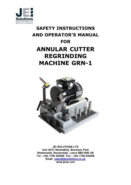
SAFETY INSTRUCTIONS<br />
AND OPERATOR’S MANUAL<br />
FOR<br />
<strong>ANNULAR</strong> <strong>CUTTER</strong><br />
<strong>REGRINDING</strong><br />
<strong>MACHINE</strong> <strong>GRN</strong>-1<br />
<strong>JEI</strong> SOLUTIONS LTD<br />
Unit 30/31 Newhallhey Business Park<br />
Rawtenstall, Rossendale, Lancs BB4 6HR UK<br />
Tel – (44) 1706 229490 Fax – (44) 1706 836299<br />
Email: sales@jeisolutions.co.uk<br />
www.jeiuk.com
TABLE OF CONTENTS<br />
Operator’s manual for Annular Cutter Grinding Machine <strong>GRN</strong>1<br />
<strong>GRN</strong>-1<br />
I. DESCRIPTION ………………………………………………………………………3<br />
1. Directed use…………………………………………………………………………..3<br />
2. Description of work………………………………………………………………......3<br />
3 Technical data……………………………………………………………………......3<br />
4 Equipment…………………………………………………………………………….4<br />
II. GENERAL SAFETY ADVISE……………………………………………………….5<br />
1. User’s duty …………………………………………………………………………..5<br />
2. Basic safety advise ………………………………………………………………….5<br />
3 Demands for operators ……………………………………………………………..6<br />
4 Special risks ………………………………………………………………………….6<br />
III. INSTALLATION………………………………………………………………………7<br />
1. Work environs……………………………………………………………………….7<br />
2. Before first instalation…………………… …………………………………....7<br />
IV. TRANSPORTATION AND STORING……………………………………………..8<br />
V. OPERATION…………………………………………………………………………9<br />
1. Components description ……………………………………………………………9<br />
2. Adjusting and configuration………………………………………………………..10<br />
2.1 Dividing disc exchange …………………………………………………….10<br />
2.2 Core drill adjusting…………………………………………………………..11<br />
3. Regular work………………………………………………………………………..12<br />
3.1 Cutter Tooth re-sharpening ……………………………………………….13<br />
3.2 Cutter Gullet surface grinding……………………………………….. .17<br />
4 Grinding disc replacement ………………………………………………………...19<br />
VI. MAINTENANCE AND REPAIR…………………………....................................20<br />
1. Cleaning and greasing …………………………………………………………….20<br />
2. Repair ……………………………………………………………………………….20<br />
2
Operator’s manual for Annular Cutter Grinding Machine <strong>GRN</strong>1<br />
<strong>GRN</strong>-1<br />
VII. EC DECLARATION OF CONFORMITY………………….................................21<br />
VIII. <strong>MACHINE</strong> TEST CERTIFICATE……………………………………………........22<br />
IX. WARRANTY CARD…………………………………………….........................23<br />
I. DESCRIPTION<br />
1. Directed use<br />
Grinding machine <strong>GRN</strong>-1 is specifically designed for HSS core drills re-sharpening.<br />
Machine is not recommended to any other applications.<br />
In the case that the <strong>GRN</strong>1 is used for any other purpose, then safety cannot be<br />
assured. In such case the operator is responsible for any machine’s damage or injury<br />
of people in the vicinity. Manufacturer recommends to read manual user very<br />
carefully, especially points regarding basic safety advice.<br />
2. Description of work<br />
Grinding machine <strong>GRN</strong>1 enables easy core drills (annular Cutter) re-sharpening.<br />
Because of it’s solid and precise construction, low supply energy demand and small<br />
dimensions the machine can be used in any place and can be installed ready for use<br />
in a short time . <strong>GRN</strong>1 was designed as user friendly machine, and our operator<br />
manual describes how to make simple work of regrinding Cutters.<br />
3. Technical data<br />
Dimensions LxWxH. [mm] 465 x 399 x 355<br />
Weight Net [kg] 15,5<br />
Supply [V] 220 – 230 V AC<br />
Motor [V / kW / rpm.] 230 / 0,18 / 2820<br />
Movement<br />
length<br />
Motor guide [mm] 70<br />
Guiding slide [mm] 162<br />
Noise level dB(A)
4. Equipment<br />
Operator’s manual for Annular Cutter Grinding Machine <strong>GRN</strong>1<br />
<strong>GRN</strong>-1<br />
Core drill’s re-sharpening machine <strong>GRN</strong>1 is delivered to the customer in carton<br />
packing, ready to use. The machine is completed with standard equipment, below:<br />
- set of dividing discs<br />
- hexagonal keys s=2,5 and s=4,<br />
- grinding disc for tool flank (Gullet) grinding<br />
- grinding disc for cutting surface (Cutting Egde) grinding<br />
- Operators Manual with warranty card.<br />
4
II. GENERAL SAFETY ADVICE<br />
1. Operators duty<br />
Operator’s manual for Annular Cutter Grinding Machine <strong>GRN</strong>1<br />
<strong>GRN</strong>-1<br />
<strong>GRN</strong>1 machine was designed and made after risk level analysis and after selection<br />
of current harmonized standards in conformity with further technical specifications.<br />
Safety operating is ensured only if operator follows with further directions.<br />
The operator has to pay special attention and be sure that:<br />
Machine is used as directed<br />
Machine is efficient,<br />
All elements strictly joined with safety work are regularly controlled<br />
Personal protection equipment is efficient and always available<br />
Operators manual is always close to the machine<br />
None of safety and warning label is removed from the machine.<br />
2. Basic safety advice<br />
Operators Manual shall be kept always close the machine in readable condition and<br />
available for any person operating with machine. In addition, the users own company<br />
instructions regarding security and health requirements have to be available for<br />
operators.<br />
Symbols placed on the machine point out that there is a danger to human life and<br />
health. Labels placed on the machine have to be kept in good readable condition<br />
Damaged or not readable labels stall be replaced immediately.<br />
Always wear safety glasses during machine work.<br />
Grinding dust can be danger for your eyes.<br />
Remove of the grinding disc protection is only permissible for<br />
grinding disc replace. During machine’s work protection has to be<br />
always mounted.<br />
5
3. Demands for operator<br />
Operator’s manual for Annular Cutter Grinding Machine <strong>GRN</strong>1<br />
<strong>GRN</strong>-1<br />
Before grinding disc replacement or machine displacement always<br />
disconnect it from electric supply.<br />
WARNING!!! LASER. Machine <strong>GRN</strong>1 is equipped with laser.<br />
In order to avoid eye injury laser CANNOT be directed into the<br />
human eyes.<br />
Only people familiar with this Operators manual, can be allowed to work with <strong>GRN</strong>1<br />
core drill grinding machine. Any operator who did not get to know this operators<br />
manual contents before starting the machine, maintenance or service, may cause a<br />
dangerous situation for the user’s and neighbouring persons safety.<br />
Do not operate the machine whilst being under the influence of alcohol.<br />
4. Special risks<br />
Before machine start up:<br />
Check for any visible damages. Defects must be removed immediately.<br />
Machine can work only when is in 100% efficient<br />
Do not start machine if some damages or lack of equipment are observed<br />
Do not start machine in vicinity of flammable materials or in vicinity of fuel<br />
vapours.<br />
Check up regularly power supply cord.<br />
- Repair open electrical connections,<br />
- Replace electric cables immediately if damaged,<br />
- Never clean up electric equipment with water<br />
Do not dismantle safety protection elements<br />
Machine modification<br />
No modifications of the machine are allowed. Only original parts should t be used in<br />
order to replace some spare parts and accessories. Mentioned spare parts are<br />
constructed only for this machine. Read the chapter “General Safety Advice”<br />
6
III. INSTALLATION<br />
1. Work environment<br />
Use <strong>GRN</strong>1 machine only in dry rooms<br />
Environment temperature +5° ÷ +50° ·C<br />
Humidity max. 90% (protect against condensing)<br />
Place machine on solid bench<br />
Pay attention for safe machine placing<br />
Machine’s work place has to ensure a vibration free motor work<br />
Operator’s manual for Annular Cutter Grinding Machine <strong>GRN</strong>1<br />
<strong>GRN</strong>-1<br />
To avoid machine’s damage and series injury when starting the<br />
machine, following steps are necessary to be taken:<br />
Ensure that all parts and tools which not consist the machine<br />
( allen keys, screws) are removed from machine vicinity.<br />
Check condition of grinding disc.<br />
Read also the chapter” General Safety Advice”<br />
Always wear safety glasses.<br />
2. Check before first installation<br />
Check up the condition of electric connections, and in case of extension cord<br />
wear, check up the condition above. In the case of any damage, the cord<br />
should be immediately replaced. This operation must be carried out by<br />
qualified electrician or in a certified service point.<br />
Check up fixation of all parts.<br />
Check up if the electric parameters of supply correspond to required data<br />
placed in this manual and on the machine’s name plate. In case divergence<br />
appears always take into consideration data given on the machine’s name<br />
plate.<br />
Check up if slide way moves without excessive frictional<br />
resistance. Machine can be only connected to the net equipped with<br />
earth protective pin. In case of non correct connection of grinding<br />
machine an electric shock may occur.<br />
In case, the plug does not suits to the socket, a qualified<br />
electrician intervention is necessary, in order to fit the plug and the<br />
socket. Any wilful exchanges in electric circuit of grinding machines<br />
are permissible.<br />
Warning!<br />
7
Operator’s manual for Annular Cutter Grinding Machine <strong>GRN</strong>1<br />
<strong>GRN</strong>-1<br />
Never start the machine if some equipment element is missed, or machine is not<br />
carefully assembled. Not respecting this prohibition may cause the accident and<br />
serious injury. Avoid fingers contact with grinding disc, or other dangers in case the<br />
grinding disc pushes away from the shaft.<br />
IV. TRANSPORT AND STORING<br />
Storing conditions<br />
Machine is delivered in original factory packing. We recommend for long-term storing<br />
to keep machine in dry surroundings in factory pacing, in temperature from -20° C do<br />
50° C.<br />
Transport conditions<br />
Machine is designed for hand loading and transporting in work place. For long<br />
distances can be transported by any transport medium. Please take care of you to<br />
prevent the machine’s movement on slide ways under inertial force.<br />
Before machine displacement:<br />
Turn off machine with button on position”0”<br />
Pull out the power cord from the socket<br />
Check up the condition of screws elements.<br />
Carry over the machine holding the machine’s base with both hands<br />
Warning!<br />
In any case:<br />
Do not use power cord to move the machine<br />
Do not carry over machine with rotating grinding disc when replacing the<br />
machine<br />
-in order to change the machine’s position.<br />
Avoid contact with the disc guard, adjusting elements and laser indicator body.<br />
8
V. OPERATION<br />
1. Components description<br />
1. Motor<br />
2. Motor feed screw<br />
3. Laser<br />
4. Motor switch<br />
5. Grinding disc guard fixing<br />
6. Grinding disc guard<br />
7. Laser arm<br />
8. Motor slide way<br />
Operator’s manual for Annular Cutter Grinding Machine <strong>GRN</strong>1<br />
<strong>GRN</strong>-1<br />
9. Wellhead support<br />
10. Core drill holder support<br />
11. Dividing disc<br />
12. Support slide way<br />
13. Star wheel with screw<br />
14. Bumper handle<br />
15. Micrometric screw<br />
16. Weldon Arbor 19,05mm<br />
9
2. Adjusting and configuration<br />
Operator’s manual for Annular Cutter Grinding Machine <strong>GRN</strong>1<br />
<strong>GRN</strong>-1<br />
2.1. Dividing disc exchange<br />
Dividing discs (point 6.1. pos. 11) of <strong>GRN</strong>1Grinding machine are responsible for<br />
accurately re-sharpening of core drill depending on the number of teeth. The basic<br />
equipment of machine consist of following dividing disc: T - 8 for core drills with 4 or 8<br />
teeth, T - 10 for core drills with 5 or 10 teeth, and T - 6, T - 7, T - 9, (for core drills<br />
with 6, 7, 9 teeth).<br />
Dividing disc exchange<br />
Choose the dividing disc suitable for the number of<br />
core drill teeth. In order to exchange the dividing<br />
disc, first turn the star wheel in CW direction until the<br />
fixing screw (a) appears in upper position. Tight the<br />
bolt (b) with hex key 2,5. Untighten the screw with<br />
star wheel (pt 6.1. pos. 13) in CCW direction<br />
Untighten screw (a) on dividing disc (use hex key<br />
2,5)<br />
and pull out the disc.<br />
Dividing disc assembly<br />
Place the chosen dividing disc on the spindle. It is<br />
important to draw attention, that screw (a) appears<br />
under the spindle slot (see drawing.). Screw gently<br />
the screw (a) with hex key 2,5) to position the slot<br />
(do not tighten). Tight the screw with star wheel in<br />
CW direction. Next tight screw (a) placed on dividing<br />
disc and loosen the screw (b) (upper drawing).<br />
10
2.2. Core drill adjusting<br />
Operator’s manual for Annular Cutter Grinding Machine <strong>GRN</strong>1<br />
<strong>GRN</strong>-1<br />
Warning! Edges of core drills are sharp. Please avoid injury!<br />
Turn the arbor holder onto position 90 ° (see<br />
drawing.)<br />
When placing the core drill inside the arbor,<br />
please draw your attention the fixing screw<br />
locates with the cylindrical surface of Weldon<br />
shank ( not flat surface) of the core drill. (Do<br />
not tighten the screw). This is necessary to<br />
avoid the core drill position change during<br />
screw tight, what could result incorrect set up.<br />
The laser ray enables core drill accuracy<br />
positioning in the arbor (right drawing) .<br />
Wheel head support (pt 6.1. pos. 9) has got<br />
white line (see drawing). During laser ray<br />
positioning, its light must be always on this line<br />
located . This is the method of basic laser ray<br />
positioning or its new positioning.<br />
11
Operator’s manual for Annular Cutter Grinding Machine <strong>GRN</strong>1<br />
<strong>GRN</strong>-1<br />
With the spindle of laser indicator guiding, set up laser indicator, to fit exactly to the<br />
external cutting edge (see drawing).<br />
Laser ray is switched on by small button placed on cylindrical indicator’s body. Now<br />
the user should turn the cutter slightly in the arbor, in order that the laser ray lights up<br />
exactly the on the external cutting edge . Fix the cutter in this position tightening the<br />
screw, placed on the cylindrical surface of Weldon arbor with hex key 4.<br />
!! MARK THE POSITIONED TEETH WITH THE MARKER!<br />
3. Regular work<br />
Always wear glasses during re-sharpening works.<br />
There are two tooth forms of core drills. Core drills with flat tooth and with V-shape<br />
tooth. Standard type core drills are V shape tooth. Non-standard core drills are<br />
equipped alternately with flat and V-shape tooth. This machine is designed to resharpen<br />
in first line tooth on internal side and next on external side. In case of nonstandard<br />
core drill re-sharpening first are re-sharpen V-shape tooth and next flat<br />
tooth.<br />
12
3.1. Core drills re-sharpening<br />
Operator’s manual for Annular Cutter Grinding Machine <strong>GRN</strong>1<br />
<strong>GRN</strong>-1<br />
Core drills, although available in two sorts are manufactured by different<br />
manufacturers.<br />
If core drills manufacturer provides user with information regarding re-sharpening<br />
parameters of tool, it is recommended to apply this settings. The following data<br />
below gives a guide only of the required angle settings<br />
Tooth no HSS Steel<br />
Support Scale Arbor angle<br />
Surface Intern. Extern. Intern. Extern.<br />
4 20° 7,5° 7,5° 15°<br />
5 20° 7,5° 7,5° 15°<br />
6 20° 7,5° 7,5° 15°<br />
7 20° 7,5° 7,5° 15°<br />
8 20° 7,5° 7,5° 15°<br />
9 20° 7,5° 7,5° 15°<br />
10 20° 7,5° 7,5° 15°<br />
11 20° 7,5° 7,5° 15°<br />
12 20° 7,5° 7,5° 15°<br />
13
Operator’s manual for Annular Cutter Grinding Machine <strong>GRN</strong>1<br />
<strong>GRN</strong>-1<br />
Core drill setting for internal surface re-sharpening<br />
14
First step.<br />
Set up the angle on wheel head support at 20 °<br />
Set up the arbor angle at 7,5 °<br />
Operator’s manual for Annular Cutter Grinding Machine <strong>GRN</strong>1<br />
<strong>GRN</strong>-1<br />
!! Remember to use the correct dividing disc !!<br />
After both angles settings, move the cutter with the guide and motor feed mechanism<br />
to the grinding disc. Re-sharpen the tooth which is directed into the middle of grinding<br />
disc, nearest to the “3 o’clock” position. (This one which position was settled up with<br />
the laser ray and marked with the marker).<br />
Move the support up to the tooth contact with the grinding disc. Lock the handle of<br />
the bumper in this position (see drawing).<br />
With micrometric screw move back the guide slightly, just so the grinding disc did not<br />
touch the next tooth.<br />
Start re-sharpening the tooth from internal surface, mowing the guide forward and<br />
backwards. Motor feed should be realised carefully and with the same value for all<br />
teeth.<br />
After the first tooth re-sharpening , move back the guide and turn the star wheel in<br />
CW direction until the dividing disc will match the next position. Do not change the<br />
motor feed setting. Repeat above work until all teeth will be re-sharpened.<br />
15
Operator’s manual for Annular Cutter Grinding Machine <strong>GRN</strong>1<br />
<strong>GRN</strong>-1<br />
Core drill setting for external surface grinding<br />
Set up the angle 7,5 °on<br />
wheellhead support<br />
Set up the 15 °angle on<br />
arbor<br />
16
Operator’s manual for Annular Cutter Grinding Machine <strong>GRN</strong>1<br />
<strong>GRN</strong>-1<br />
After setting the angle, move the cutter with the guide and feed motor mechanism<br />
towards the grinding disc.<br />
Do not re-sharpen the tooth marked earlier with the marker, but the next one placed<br />
below.<br />
Move the support until the teeth will get in touch with grinding disc. Lock the<br />
bumper’s handle in this position (see drawing).<br />
With the micrometric screw, move back the guide, just to avoid the contact of next<br />
tooth with grinding disc.<br />
Now you can start the sharpening process from the marked site, moving the guide<br />
forward and backwards. The motor’s guide feed should be adjusted carefully and<br />
with the constant value for each tooth.<br />
After the first tooth has been sharpened, move back the guide, turn the star wheel in<br />
CW direction, down to the dividing disc new position.<br />
Do not change the motor feed adjustment. Repeat described above functions till all<br />
teeth will be re-sharpened. Carry out the process over several passes until the<br />
cutting edge is completely reground.<br />
3.2. Gullet grinding<br />
After intensive use, and after several re-grinds, it is necessary to reform the gullet<br />
area between each tooth, to ensure that the cutter performs its hole cutting operation<br />
correctly. Without a correct gullet, the cutter will not release its solid slug after the<br />
operation.<br />
In the case of reforming the gullet, the second grinding disc with a different geometry<br />
of grinding surface, should be placed on machine’s spindle.<br />
17
Operator’s manual for Annular Cutter Grinding Machine <strong>GRN</strong>1<br />
<strong>GRN</strong>-1<br />
Adjust the angle 50 °on support scale<br />
Adjust the angle 25 °on the arbor scale<br />
Mentioned adjustments are not obligatory for all cutters types. Move the cutter into<br />
the grinding disc ( when motor is ON) and if necessary correct the cutter adjustment.<br />
The angle can fluctuate in range 15° ÷ 30°<br />
18
Operator’s manual for Annular Cutter Grinding Machine <strong>GRN</strong>1<br />
<strong>GRN</strong>-1<br />
After setting the cutter position, move the core drill with guide and motor feed<br />
mechanism towards the grinding disc. Grind the gullet area of the core drill with<br />
above mentioned grinding disc. Do not grind the tooth which was earlier marked with<br />
marker, but the surface of the next tooth.<br />
Move the core drill along the grinding disc in a stationary condition till the Gullet<br />
touches the diamond disk. Set the lateral stop and the fine tuner in such a way that<br />
the Gullet surface can be ground.<br />
Now grind the Gullet Surface which you have set. Delivery through the fine tuner<br />
should be low, and it should be uniform for all the Gullet surfaces. After grinding the<br />
first Gullet surface, pull the guidance carriage back and turn the star-shaped screw<br />
head in the clockwise direction (direction of arrow) right up to the next section. You<br />
can position the next stretched surface in this manner. Do not alter the motor feed<br />
and the fine tuner position.<br />
Repeat the grinding process till all the Gullet surfaces have been ground.<br />
19
4. Grinding disc replacement<br />
Operator’s manual for Annular Cutter Grinding Machine <strong>GRN</strong>1<br />
<strong>GRN</strong>-1<br />
Unplug the machine from the power supply before grinding disc replacement<br />
Remove core drill from the arbor<br />
Grinding disc replacement<br />
Turn out the wing-nut fixing down and up.( see<br />
drawing) remove the guard. The grinding disc is<br />
equipped with hexagonal screw placed on the flange.<br />
Loosen screw with hexagonal key 2,5 and remove the<br />
grinding disc from machine spindle.<br />
Grinding disc assembly<br />
Place the proper grinding disc on machine’s spindle (<br />
\keep approx. 5mm distance from internal surface of<br />
guard) and tighten the screw. Then re-assemble the<br />
grinding disc guard.<br />
20
VI. MAINTENANCE AND REPAIR<br />
1. Cleaning and greasing<br />
Operator’s manual for Annular Cutter Grinding Machine <strong>GRN</strong>1<br />
<strong>GRN</strong>-1<br />
The <strong>GRN</strong>1 core drill grinding machine should be cleared up from the dust particles at<br />
least once a week with delicate brush. After clearing all movables parts, the unit<br />
should be greased with a thin layer of machine oil.<br />
Motors guides shall be greased every 6 months with thin layer of grease on the<br />
internal surfaces.<br />
Warning!!<br />
Cleaning machine with water is not permissible. Water use may cause machine’s<br />
defect or damage.<br />
Before cleaning machine it should be unplugged from the power supply.<br />
2. Repair<br />
Repair of machine main components such as guides or wheelhead, can be made<br />
only by the manufacturer. Mentioned parts are responsible for accurate machine’s<br />
work.<br />
21
VII. EC DECLARATION OF CONFORMITY<br />
We<br />
<strong>JEI</strong> solutions<br />
Rawtenstall, Rossendale<br />
Operator’s manual for Annular Cutter Grinding Machine <strong>GRN</strong>1<br />
<strong>GRN</strong>-1<br />
Declaration of compatibility<br />
declare with full responsibility that product:<br />
Core drills grinding machine <strong>GRN</strong>-1<br />
which the declaration applies to is in accordance with the following standard(s)<br />
placed below:<br />
EN 50144-1, and satisfies safety regulations of guidelines: 2006/95/EC, 2006/42/EC<br />
Białystok, 2010-02-25<br />
___________________________<br />
Chairman<br />
22
VIII. <strong>MACHINE</strong> TEST CERTIFICATE<br />
Product: <strong>JEI</strong>-<strong>GRN</strong>1<br />
Serial No. _______________________<br />
Date of test: _______________________<br />
Electric test results:<br />
Test with sinusoidal voltage<br />
of 1000 V and frequency 50 Hz<br />
Resistance of the protective circuit [Ω]<br />
Machine control card<br />
Operator’s manual for Annular Cutter Grinding Machine <strong>GRN</strong>1<br />
<strong>GRN</strong>-1<br />
Test Result<br />
The above-mentioned product meets the requirements of safe usage as prescribed in standard IEC-745<br />
Name of tester ____________________<br />
Quality Control ____________________<br />
23
IX . WARRANTY CARD<br />
WARRANTY CODITIONS<br />
Operator’s manual for Annular Cutter Grinding Machine <strong>GRN</strong>1<br />
<strong>GRN</strong>-1<br />
Core drill grinding machine <strong>JEI</strong>-<strong>GRN</strong>1<br />
1. The Manufacturer grants the Buyer a guarantee for a 12 months period from<br />
date of sold.<br />
2. The Buyer lost the warranty in case of:<br />
- Warranty sense remove;<br />
- Non permissible repairs or changes;<br />
- Use of machine not correct with destiny described in Machine’s Manual;<br />
- Defects which occurred to be caused another than material defects or<br />
assembly mistakes.<br />
3. Guarantor is responsible to repair the machine in reasonable time of 14 days<br />
from delivery time the machine to the service point, and 21 days in case of<br />
delivery by post.<br />
4. Warranty does not cover: safety fuses, grinding disc, regular equipment of<br />
machine , electric brushes of the motor and the damages may occur during<br />
regular wear of machine .<br />
5. The Seller is not responsible for damages of machine resulted by not proper<br />
way of transport.<br />
Description<br />
Produce date:............. ……....................Serial No...................................................<br />
Purchase date...........................................................................................................<br />
Seller’s description and signature.............................................................................<br />
24