Farm buildings; a compilation of plans for general farm barns, cattle ...
Farm buildings; a compilation of plans for general farm barns, cattle ...
Farm buildings; a compilation of plans for general farm barns, cattle ...

Create successful ePaper yourself
Turn your PDF publications into a flip-book with our unique Google optimized e-Paper software.
ItBh<br />
iixii; :<br />
.;;'<br />
':''•<br />
'<br />
;<br />
,<br />
•<br />
:<br />
'<br />
:<br />
. : ;'
HA<br />
CORNELL<br />
UNIVERSITY<br />
COLLEGE OF<br />
ARCHITECTURE<br />
LIBRARY .
ia ^ . ft--<br />
J> fVV)<br />
DATE DUE<br />
«***&*,<br />
MIMrCOlNU-S.A<br />
Cornell University Library<br />
NA8201.B74<br />
<strong>Farm</strong> <strong>buildings</strong>; a <strong>compilation</strong> <strong>of</strong> <strong>plans</strong> fo<br />
3 1924 015 223 765
Cornell University<br />
Library<br />
The original <strong>of</strong> this book is in<br />
the Cornell University Library.<br />
There are no known copyright restrictions in<br />
the United States on the use <strong>of</strong> the text.<br />
http://www.archive.org/details/cu31924015223765
w<br />
OS<br />
H<br />
K<br />
I"<br />
<<br />
a sWB<br />
o<br />
OS O<br />
W m<br />
W<br />
K<br />
W<br />
J
FARM<br />
BUILDINGS<br />
, * < , , , A COMPILATION OF ,,,,,,<br />
PLANS FOR GENERAL FARM BARNS,<br />
CATTLE BARNS, HORSE BARNS, SHEEP<br />
FOLDS, SWINE PENS, POULTRY<br />
HOUSES, SILOS, FEEDING RACKS, ETC.<br />
ALL REPRESENTING CONSTRUCTION IN ACTUAL USE.<br />
CHICAGO:<br />
SANDERS PUBLISHING CO.<br />
1905.
tjto^leej<br />
COPYRIGHT, 1904.<br />
SANDERS PUBIJSHING COMPANY,<br />
ALL RIGHTS RESERVED.
PUBLISHER'S NOTE.<br />
1 'HIS is not a book <strong>of</strong> proposed <strong>plans</strong> <strong>for</strong> <strong>farm</strong> <strong>buildings</strong>, but <strong>for</strong> the most part is<br />
* a presentation <strong>of</strong> actual construction by practical men. It is in the main a com-<br />
pilation <strong>of</strong> the best <strong>plans</strong> contributed to The Breeder's Gazette by the <strong>farm</strong>ers and<br />
stockmen <strong>of</strong> the United States in recent years. Many different types are illustrated.<br />
Different <strong>farm</strong>s, different latitudes and different methods <strong>of</strong> management demand an<br />
infinite variation in the style, dimensions and detail <strong>of</strong> American <strong>farm</strong> <strong>buildings</strong>.<br />
In barn building as in the planning <strong>of</strong> the <strong>farm</strong> home, nearly every individual<br />
has his own peculiar ideas and tastes. It is rarely that one is entirely satisfied with<br />
what a neighbor has done in such matters. At the same time it is clear that many<br />
<strong>general</strong> propositions and many matters <strong>of</strong> detail possessing real value to a prospective<br />
builder may be gleaned from a study <strong>of</strong> what successful <strong>farm</strong>ers in different parts <strong>of</strong><br />
the country have already carried out.<br />
In the belief that many helpful hints will be found in these pages and to fill a<br />
persistent demand <strong>for</strong> in<strong>for</strong>mation upon the subject treated the publishers present this<br />
<strong>compilation</strong> with full confidence that it will meet with <strong>general</strong> appreciation.
TABLE OF CONTENTS.<br />
PAGE<br />
Location and General Arrangement . . 11-14<br />
The Modern Barn 15-19<br />
Wing's Joist Frame 17<br />
General <strong>Farm</strong> Barns 19-38<br />
Bank Barn, A.. 33<br />
Barn <strong>for</strong> Small <strong>Farm</strong> 38<br />
Barn <strong>of</strong> Round Poles 38<br />
Basement Barn and Carriage House ... 33<br />
Circular Barn, New Type <strong>of</strong> 23<br />
<strong>Farm</strong> Barn, Good Type <strong>of</strong> 37<br />
Hay Barn, A Joist Frame 36<br />
Horses and Range Cattle, Barn <strong>for</strong>. ... 38<br />
Indiana <strong>Farm</strong> Barn 29<br />
Iowa Experiment Station Barn 25<br />
Kentucky <strong>Farm</strong> Barn 30<br />
Kentucky Stock Barn 35<br />
Lovejoy's <strong>Farm</strong> Barn 21<br />
Minnesota <strong>Farm</strong> Barn 19<br />
Ohio <strong>Farm</strong> Barn 33<br />
Small Barn. Plan <strong>for</strong> 37<br />
Stock and Hay Barn 25<br />
Stock Barn, A Small 36<br />
Umbrella Barn, The Glide 39<br />
Whitehall Cattle and Horse Barn 29<br />
Wisconsin <strong>Farm</strong> Barn 29<br />
Cattle Barns<br />
39-56<br />
Breeding Cattle, Barn <strong>for</strong> 50<br />
Corn-Belt Barn<br />
48<br />
Feeding Barn, A Cattle<br />
Feeding Cattle Loose, A Barn <strong>for</strong><br />
53<br />
54<br />
Hawkeye Cattle Barn 42<br />
Hoosier Cattle Barn 47<br />
Illinois Cattle Barn 50<br />
Indiana Cattle Barn<br />
43<br />
Iowa Cattle Barn<br />
41<br />
Kansas Cattle Barn 40, 43<br />
Missouri Barn Plan<br />
53<br />
Modern Type <strong>of</strong> Cattle Barn 49<br />
Morgan Cow Barn<br />
41<br />
Octagonal Cattle Barn<br />
47<br />
Steer Barn, An Iowa<br />
54<br />
Open-Centre Cattle Barn 51<br />
Sale Barns 55, 56<br />
Horse Barns and Stables<br />
Bank Stable<br />
Barn <strong>for</strong> Forty Horses<br />
Colt Stables, Convenient<br />
57-76<br />
TO<br />
70<br />
74<br />
Horse Barn Without Cross Ties<br />
Illinois Stallion Barn<br />
Iowa Stallion Barn<br />
Kentucky Barn <strong>for</strong> Speed Horses<br />
Kentucky Coach and Stallion Barn<br />
Light Horses, Barn <strong>for</strong><br />
McMillan's Horse Barn<br />
Montana Horse Barn<br />
Mule Barn<br />
Nebraska Horse Barn<br />
Oaklawn, Stabling at<br />
Plan <strong>for</strong> Horse Barn<br />
Plymouth Hackney Stud Stables<br />
Stallion Barn, A Modern<br />
Three-Story <strong>Farm</strong> and Horse Barn<br />
Dairy Barns<br />
Cow Barn<br />
Hygienic Dairy Barn<br />
Illinois Dairy Barn<br />
Nebraska Dairy Barn<br />
Pennsylvania Dairy Barn<br />
Round Barn<br />
Wisconsin Dairy Barn<br />
Swine Barns and Houses<br />
Farrowing Pens, Lovejoy<br />
Farrowing Pen <strong>for</strong> Early Litters<br />
Feeding Floor and Pig Houses<br />
Hog House <strong>for</strong> Sows and Pigs<br />
Illinois Hog House<br />
Maryland Hog House<br />
Morgan Hog Barn<br />
Movable Hog House<br />
Nebraska Hog House<br />
Portable Pig Pen<br />
Twenty Sows, House <strong>for</strong><br />
Sheep Barns and Sheds<br />
Baby Mutton Factory<br />
Barn with Glass-Covered Lamb Shed.<br />
Experiment Station Sheep Barn<br />
Feeding Barn <strong>for</strong> Sheep<br />
Feeding Shed <strong>for</strong> Sheep<br />
Interior Arrangement <strong>of</strong> Sheep Barn<br />
Lambing Barn <strong>for</strong> the South<br />
Lambing Shed<br />
Morgan Sheep Barn<br />
Nebraska Sheep Barn<br />
Small Sheep Barn<br />
Utah Sheep Shed<br />
page<br />
63<br />
73<br />
68<br />
71<br />
61<br />
60<br />
71<br />
62<br />
76<br />
65<br />
58<br />
64<br />
70<br />
63<br />
67<br />
77-85<br />
81<br />
82<br />
77<br />
83<br />
84<br />
77<br />
85<br />
86-97<br />
94<br />
92<br />
95<br />
90<br />
87<br />
95<br />
87<br />
94<br />
90<br />
97-110<br />
102<br />
105<br />
99<br />
107<br />
107<br />
105<br />
108<br />
109<br />
98<br />
106<br />
102
10 TABLE OF CONTENTS.<br />
Poultry Houses 111-120<br />
Convenient Poultry House 114<br />
Design <strong>for</strong> Poultry House 116<br />
<strong>Farm</strong> Hen House 115<br />
<strong>Farm</strong> Poultry House 119<br />
General Remarks Ill<br />
Hen House, A Convenient Small 120<br />
Hen House, Good Type <strong>of</strong> 117<br />
House <strong>for</strong> One Hundred and Fifty Hens 117<br />
House <strong>for</strong> Two Hundred and Fifty Hens. 118<br />
Illinois Poultry House 116<br />
Simple and Practical Ben House 118<br />
Summer Hen House 115<br />
Miscellaneous 120-177<br />
Anchoring a Barn 158<br />
Breeding Box <strong>for</strong> Swine 158<br />
Bull Stocks 160<br />
Cement and Concrete Work 129-133<br />
Cistern Making, A Hint on 173<br />
Covering Stacks, Device <strong>for</strong> 162<br />
Cribs, Granaries and Workshops 127-129<br />
Dehorning and Hog-Ringing Device. . . 159<br />
Dipping Tanks 166-172<br />
Drainage System, A <strong>Farm</strong> 173<br />
Drinking Fountain 161<br />
Feed Racks and Troughs<br />
133-138<br />
Fences 138-146<br />
Fence-Breaking Bulls, Device <strong>for</strong> 162<br />
Gates<br />
146-156<br />
Hay Barracks, Joist Frame 129<br />
Holding Hogs, Device <strong>for</strong><br />
Hog Loader, A Portable<br />
160<br />
163<br />
Hog Pen Front 157<br />
Ice Houses. . , 163-165<br />
Ro<strong>of</strong>s and Ro<strong>of</strong>ing 174<br />
Self-Sucking Cows, Devices <strong>for</strong> 158<br />
Shipping Crate <strong>for</strong> Hogs 162<br />
Silos 120-127<br />
Stalls <strong>for</strong> Cattle 175-177<br />
Ventilation <strong>of</strong> Stables 165<br />
"Wagon Rack and Stanchion 156<br />
Water Closets 174<br />
Water in the Cow Stable 174<br />
Whitewash Formula 174<br />
Water Supply, The <strong>Farm</strong> 172<br />
Water Tank <strong>of</strong> Earth 173<br />
Appendix 177-185
FARM BUILDINGS.<br />
LOCATION AND GENERAL ARRANGEMENT.<br />
The planning and construction <strong>of</strong> <strong>farm</strong> <strong>buildings</strong><br />
should be done with regard to the surrounding<br />
outside features as much, as to the interior<br />
arrangement and convenience <strong>of</strong> the rooms. It<br />
is a common error to see little <strong>for</strong>ethought taken<br />
in the placing <strong>of</strong> the <strong>buildings</strong>, in their relation<br />
to each other or to the surrounding conditions;<br />
the total disregard <strong>of</strong> a fine outlook that may<br />
have been had from the windows that are most<br />
frequented; many errors in the proper way to<br />
approach the house from the highway, and many<br />
times the utter absence <strong>of</strong> any attempt at ornamentation<br />
in the way <strong>of</strong> tree planting—nothing<br />
save bare sides and sharp angles <strong>of</strong> <strong>buildings</strong><br />
open to all winds, storms and sun heat, or the<br />
opposite extreme, burying the house in a dense<br />
shade <strong>of</strong> loneliness.<br />
Now this should not be so. When the advantages<br />
and increased value <strong>of</strong> the property as a<br />
whole are considered it is at once apparent. Any<br />
one can distinguish between a nice <strong>farm</strong>, a place<br />
where it would be a pleasure to live, and on the<br />
other hand one that is bare and uninviting. The<br />
cost is a matter <strong>of</strong> <strong>for</strong>ethought on the part <strong>of</strong><br />
the individual at the beginning in the planning<br />
<strong>of</strong> the work, and the actual material to be used<br />
y in beautifying the grounds almost always can<br />
be had <strong>for</strong> the gathering. One may easily find<br />
the time to do the work when once he has<br />
tasted <strong>of</strong> the pleasures there are in surroundings<br />
that are made attractive with trees and plants<br />
arranged to make a landscape that is ever<br />
improving and changing in scene.<br />
When a beginning is made toward embellishment<br />
<strong>of</strong> the home surroundings then there is<br />
a new birth given, the feeling <strong>of</strong> attachment<br />
that reflects back into pleasant and longing<br />
recollections <strong>of</strong> the happy lives passed there,<br />
and the far-reaching influence <strong>of</strong> cheerful home<br />
surroundings on the character and future life<br />
y <strong>of</strong> the growing generation toward the good and<br />
high <strong>of</strong> ideal life is above any estimation, besides<br />
being a source <strong>of</strong> interest and everlasting joy<br />
and pleasure alike to the owner and to all who<br />
enter here.<br />
<strong>Farm</strong>ing is not all corn. There are many fine<br />
<strong>farm</strong>s that are -only such from the fact that_<br />
there is a quiet natural park-like effect resting<br />
over the home place and if favored with a fertile<br />
soil and a kind climate how much more blest we<br />
could be if we would bring about us more <strong>of</strong> the<br />
natural beauties so abundant everywhere. This<br />
need not detract an instant from the economical<br />
operation <strong>of</strong> the <strong>farm</strong> but if practically planned<br />
should add many fold thereto.<br />
We can assume that the residence and other<br />
<strong>buildings</strong> are already placed, or that building is<br />
to be done at some future time. With respect<br />
to the all-important question <strong>of</strong> choosing the<br />
house site, the custom in the city seems to be the<br />
law without recourse in the country, in that the<br />
house must stand facing square, with the best<br />
rooms toward the public road. If a better exposure<br />
or a fine scene lies in another direction,<br />
reverse the order regardless <strong>of</strong> the highway.<br />
Again, houses are dropped in a hollow, carried<br />
to the top <strong>of</strong> a bare hill, or placed too near dusty<br />
roads or stables, making things more disagree-,<br />
able than convenience would compensate. The<br />
house should not be put on a poor or waste piece<br />
<strong>of</strong> ground just to gain a little extra tillable land>"<br />
Personal preferences should <strong>of</strong> course be taken<br />
into consideration, but as a rule many desirable<br />
locations are ignored. Among the specific directions<br />
to apply in selecting the home site are good<br />
sanitary conditions. These demand air and<br />
quick drainage <strong>of</strong> water. All this is secured on<br />
a dryish soil, slightly elevated if possible and<br />
fairly open to admit a free circulation <strong>of</strong> air.<br />
Any protection against prevailing north and west<br />
winds in the winter season, such as hills, trees<br />
or any other natural objects in the track <strong>of</strong> regular<br />
storms, should be made use <strong>of</strong>, but cool and<br />
refreshing winds should not be hindered in their<br />
direction during the heated season.<br />
The distance from the highway is hardly a<br />
matter <strong>of</strong> importance. If the best place is 400'<br />
from the road it ought to be chosen over another<br />
less desirable, though 200' nearer. Besides this<br />
an entrance approach <strong>of</strong> reasonable length, if<br />
properly laid<br />
add much to<br />
out among a > grove <strong>of</strong> trees,<br />
the dignity and bearing <strong>of</strong><br />
will<br />
the<br />
place. The relation <strong>of</strong> the house and barn should<br />
be such that they do not appear as a part <strong>of</strong><br />
each other and in driving to the house one is not<br />
led first through yards and past gaping barn
12 FARM BUILDINGS.<br />
doors. The barn should occupy a position so<br />
that the prevailing winds will carry the stable<br />
odors in a direction away from the house and<br />
not toward it, as is <strong>of</strong>ten the case. The exact<br />
position and arrangement <strong>of</strong> the out-<strong>buildings</strong><br />
and enclosures will be according to their use,<br />
and to be convenient should be few and com-<br />
• pact and not scattered over a whole area. Pens,<br />
sheds and stacks should not be conspicuous in a<br />
<strong>general</strong> front view.<br />
In country houses broad simple design is much<br />
^to be preferred. All about a house <strong>of</strong> this order<br />
there is a quiet dignity and homelike restfulness<br />
that, is in pleasing harmony with every rural<br />
landscape. The rooms should be few and large.<br />
The veranda is right if one step up from the<br />
ground and at least 10' wide, and a portecochere<br />
or carriage porch should be a part <strong>of</strong><br />
every country house, as it surely is a com<strong>for</strong>t<br />
when rainy or windy to drive up to the door<br />
^ under a ro<strong>of</strong>. Especially is the excessive use<br />
<strong>of</strong> all "ginger-bread" mill work in gable ornaments,<br />
railings, brackets and the like to be discouraged,<br />
as such detail soon falls into decay and<br />
is a constant item <strong>of</strong> repairing and the greater<br />
part <strong>of</strong> it is vulgar and meaningless. Likewise<br />
the use <strong>of</strong> many discordant colors in outside<br />
paintin? is not in keeping with surroundings; a<br />
modest neutral shade that blends with the fields<br />
and trees is the correct- one. Eed is a good and<br />
cheap color <strong>for</strong> <strong>barns</strong> and possibly <strong>for</strong> houses<br />
also, but it should be shaded down and the glare<br />
and flash taken <strong>of</strong>f.<br />
' Features <strong>of</strong> the natural landscape should<br />
receive great consideration, as it is these that<br />
give character to the <strong>farm</strong>stead. A grove <strong>of</strong><br />
noble trees on a slight eminence would at once<br />
suggest the future home site. In the choice <strong>of</strong><br />
views here is a suggestion as to the points ,<strong>of</strong><br />
interest: first would come the immediate surroundings<br />
made beautiful with lawn, trees and<br />
shrubs, and farther out the adjacent fields <strong>of</strong><br />
growing crops or pasturing animals are constantly<br />
in mind. The neighboring <strong>farm</strong> houses,<br />
the travel on the highway, or a speeding railroad<br />
train are all <strong>of</strong> every-day attraction. The<br />
landscape that is characteristic <strong>of</strong> the particular<br />
country, a broad far prairie scene that holds<br />
hands with the horizon beyond; hills or woodlands<br />
bounding the view with their picturesque<br />
sky line, a river or winding stream with wooded<br />
shores and spanning bridge or a lake <strong>of</strong> broad<br />
expanse and quiet surface—all these are everlasting<br />
scenes <strong>of</strong> delight and inspiration.<br />
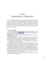
Now as a practical demonstration <strong>of</strong> how a<br />
<strong>farm</strong> can be developed in a complete and intelligent<br />
manner, reference to the example shown by<br />
the plan will serve to clinch the essential points<br />
mentioned. The plan represents a <strong>general</strong><br />
scheme <strong>for</strong> the layout <strong>of</strong> a 160-acre prairie <strong>farm</strong>.<br />
There are no trees on the tract <strong>of</strong> any importance<br />
; the surface is slightly rolling with no<br />
prominent elevations anywhere—in all a typical<br />
grain and stock <strong>farm</strong>; corn, oats, some wheat,<br />
hay and pasturage, almost all sold <strong>of</strong>f in the<br />
finished products <strong>of</strong> beef and pork. It is believed<br />
that this scheme comes very near an economical<br />
use <strong>of</strong> all <strong>of</strong> the land combined with a beautification<br />
<strong>of</strong> the home surroundings, a park-like<br />
entrance and approach drive, a commanding<br />
position <strong>for</strong> the house and the <strong>farm</strong> <strong>buildings</strong><br />
centrally located and accessible from all parts<br />
<strong>of</strong> the premises.<br />
The house is placed in a ten-acre piece, which<br />
,/may be properly called the home plot. Here are<br />
collected all the <strong>buildings</strong> (except the barn and<br />
feeding lot), orchard, vegetable and fruit garden,<br />
shaded lawn, flowers and all that goes into daily<br />
life. This plan leaves no waste ground; everything<br />
is compactly arranged and yet in such a<br />
manner as to allow the extension <strong>of</strong> any particu-<br />
lar part without interfering with another.<br />
The residence is about 700' from the highway<br />
and stands in the southwest corner <strong>of</strong> the<br />
home plot, the ground sloping <strong>of</strong>f gently to the<br />
south. All the main rooms have a south and east<br />
exposure. It is approached from the public highway<br />
on a curve which is in the direction <strong>of</strong> the<br />
most traffic (the city in this case). This is a<br />
much better way than entering at right angles<br />
and adds greatly to the appearance <strong>of</strong> the<br />
entrance and does not allow a direct view up the<br />
drive from the road. The drive slants over<br />
until within about 20' <strong>of</strong> the fence; it then<br />
parallels the fence in a straight line to the barn.<br />
A short distance from the house a branch road<br />
leads over on a gradual curve to the carriage<br />
porch, passing underneath it; the curve then<br />
continues and joins the main road to the barn.<br />
By placing the house about 70' or so from the<br />
main drive all clatter and noise <strong>of</strong> teaming is<br />
to a large degree shut away from contact with<br />
the rooms and a nice lawn space comes up to<br />
the house on that side. This entrance road is<br />
ten feet wide, the branch nine feet, graded with<br />
gravel from a near-by pit and smoothly surfaced<br />
<strong>of</strong>f with a crown just sufficient to turn the water.<br />
The barn is 250' from the house and is set<br />
40' into the ten-acre pasture to the west,<br />
with a silo on the north side convenient alike to<br />
the barn and feeding lot. Another building is<br />
put up 80' directly east <strong>for</strong> <strong>general</strong> storage<br />
purposes <strong>of</strong> machinery, wagons, supplies and<br />
repair shop. The space between the barn and<br />
storage house should be drained and bedded with<br />
gravel to serve as a <strong>general</strong> movement yard and<br />
entrance <strong>for</strong> both <strong>buildings</strong>; a place to set up<br />
the shredding outfit, grinding, unloading and
LOCATION AND GENERAL ABHANQEMENT. 13<br />
the like. Water is piped into this yard and to<br />
the house from the tank and well just back <strong>of</strong> the<br />
storage house. A poultry shed is at the north <strong>of</strong><br />
this building.<br />
A good big orchard contains about 125 trees,<br />
including apples, pears, plums and cherries,<br />
manent than the raspberries and blackberries,<br />
which can be moved bade and <strong>for</strong>th into the<br />
nursery ground when they get old and worn out<br />
'in one place; currants and gooseberries are also<br />
planted. The strip <strong>for</strong> nursery purposes does<br />
good service in growing trees and bushes to set<br />
m^sm^^^<br />
JTO. 1—PLAN FOB LAYING OUT A 160-ACRE FARM AND I\ARM HOME.<br />
which will give plenty <strong>of</strong> fruit <strong>for</strong> home use and<br />
much to sell. A fence is run along the lower side<br />
<strong>of</strong> the orchard ; then the pigs can be turned in any<br />
time to consume the fallen fruit, although the<br />
trees will be cared <strong>for</strong> the same as a crop <strong>of</strong> corn.<br />
One acre is given to small fruits. The grapes are<br />
put next the orchard because they are more per-<br />
out in the future. A row <strong>of</strong> hot-beds and frames<br />
is useful in many ways; it is protected along<br />
the north with evergreen trees. The vegetable<br />
garden <strong>of</strong> one and one-quarter acres will give<br />
abundance <strong>of</strong> good things and all that is left over<br />
the pigs will take as dessert. The strawberry<br />
patch is moved about the garden every year or
14 FARM BUILDINGS.<br />
two. Asparagus and rhubarb are along the fence.<br />
A lawn space bounds the house on all sides,<br />
varying in width from 150' to 200'. It is not<br />
necessary, however, to keep it closely mown. In<br />
the rear the grass covers the clothes-drying<br />
space; further back are the beehives and a place<br />
<strong>for</strong> the wood pile. The grounds about the house<br />
are planted with trees <strong>for</strong> shade and beauty; a<br />
place <strong>for</strong> children to play and climb and a source<br />
<strong>of</strong> recreation and ease <strong>for</strong> the older members <strong>of</strong><br />
the family. As to the kinds used <strong>for</strong> this p'Urpose<br />
: in making the ground work or foundation<br />
<strong>of</strong> the scene use such native trees as are found<br />
''growing in the immediate locality ; elms, maples,<br />
lindens and. ash are in greater abundance. All<br />
these trees are reasonably quick in growth, bear<br />
transplanting well and will there<strong>for</strong>e prove a<br />
success from the start. Hawthorns, wild cherries,<br />
plums and crab apples, juneberry, dogwood<br />
and redbud are planted in the places to thicken<br />
up and mass with the other trees; occasionally<br />
they appear in detached groups or specimens by<br />
themselves. They will lend variety and charm<br />
to the surroundings in the springtime with their<br />
white, pink and red flowers, and in the autumn<br />
many <strong>of</strong> them close the growing season with a<br />
contrast <strong>of</strong> scarlet fruits and golden-hued foliage.<br />
Along the entrance road the work is done in<br />
a like manner. Evergreen trees— pines and<br />
spruce—are planted in clumps; at the left hand<br />
side <strong>of</strong> the entrance gate is one group,- farther<br />
up on the other side another. On the west and<br />
northwest sides <strong>of</strong> the house are thick groups<br />
'to lessen the prominence <strong>of</strong> the barn, to check<br />
cold winds and vary the effect with the deciduous<br />
trees. Trees are placed along those sides <strong>of</strong> the<br />
barn ; seen from the highway they will s<strong>of</strong>ten the<br />
blank barn side and give a proper setting to the<br />
building as a whole. The gable and tower<br />
appearing among the tree tops will mark a distinctly<br />
rural scene. To protect the <strong>buildings</strong> and<br />
feeding lots somewhat against the direct <strong>for</strong>ce <strong>of</strong><br />
cold northwest winds groups <strong>of</strong> Norway spruce<br />
are planted in alternate groups with deciduous<br />
trees, as shown in the plan, north <strong>of</strong> the barn<br />
and act as a wind check.<br />
The entrance gate should be set in at least<br />
thirty feet from the fence line, leaving an open<br />
space <strong>of</strong> 60' to 70' on each side <strong>of</strong> the drive, as<br />
shown in the plan. This space is planted with<br />
trees, and if an elm is planted on each side <strong>of</strong> the<br />
gate a beautiful arching effect will be had over<br />
the <strong>for</strong>mal entrance to the place.<br />
A tree to appear in all its natural beauty<br />
should spread its branches out and down to the<br />
ground on all sides. Never trim all the branches<br />
<strong>of</strong>f and expose a bare stem, nor hack <strong>of</strong>f the ends<br />
<strong>of</strong> branches and make a stubby, broom-shaped<br />
thing. If a good set <strong>of</strong> roots is dug with the<br />
tree no pruning is required. Pruning <strong>of</strong> ornamental<br />
trees is properly a thinning out in the<br />
center <strong>of</strong> minor twigs and branches. Let the<br />
tree develop into its own natural <strong>for</strong>m. Cutting<br />
can never accomplish this.<br />
Shrubs should be massed in a border along the<br />
entrance drive next to the fence, to add variety<br />
with their foliage and flowers at different times.<br />
An irregular massing <strong>of</strong> shrubbery <strong>for</strong>ms a boundary<br />
belt along the east and south sides <strong>of</strong> the<br />
house. The lawn extends out on those sides to<br />
this border; along the edges next the grass is the<br />
place <strong>for</strong> hardy flowers, native perennials and<br />
any other favorites that are desired; here they<br />
will be in charming contrast with the lawn and<br />
bushes. The kinds <strong>of</strong> shrubs used are wild native<br />
species found growing in the neighborhood, such<br />
as dogwoods (the red^branched and others),<br />
sumach, elderberry, wild rose, Indian currant,<br />
snowballs, spiraea, lilacs, mock-orane and<br />
honeysuckles. Japan quince and <strong>for</strong>sythia are<br />
nice in places where they are seen from the windows,<br />
because <strong>of</strong> their early blossoms. So are<br />
those early flowering trees, such as juneberry,<br />
wild goose plum, Judas tree and dogwood. Such<br />
early spring flower scenes <strong>of</strong> color are delightful<br />
to children or invalids who are confined to the<br />
house until the weather becomes, milder. Vines<br />
ramble all over the porch columns and up<br />
the fireplace chimney on the west side <strong>of</strong> the<br />
living room.<br />
The views from the house are indicated by the<br />
converging lines-. (Fig- 1-) Three different<br />
scenes are open from the living room: We have<br />
the veranda along the south and east sides <strong>of</strong><br />
this room. To the west the sight is across open<br />
fields to the lowering sunset. Different openings<br />
through the trees give glimpses <strong>of</strong> the life on the<br />
highway. Out <strong>of</strong> the dining room the picture<br />
is one <strong>of</strong> sunlight and shadow, over the open<br />
lawn, under the trees to the color <strong>of</strong> flowers.<br />
The kitchen and rear porch are shaded in the<br />
summer; a walk connects them with the drive;<br />
storage room is ample; the <strong>of</strong>fice is handy to the<br />
drive and an outlook to the west; the carriage<br />
porch and entrance hall face west.<br />
In conclusion we may say that the <strong>farm</strong> home<br />
stands as the central feature, with the <strong>barns</strong> in<br />
a subordinate position. They are then brought<br />
into harmonious relation with each other<br />
through the artistic planting <strong>of</strong> native trees.<br />
Orchard and gardens are grouped as nearby<br />
accessories and the grounds about the house are<br />
further enriched with shrubs and flowers. The<br />
drive and walks allow convenient and easy access<br />
to all places and lead in a natural manner to the<br />
highway. Along the highway and in groups<br />
about the boundaries and cross fences trees are<br />
planted as per introduction and outline.
Do you want a barn? Have you any definite<br />
idea <strong>of</strong> what it is that you want? Have you<br />
carefully considered first your means, then your<br />
needs, then the needs <strong>of</strong> years to come? Is it<br />
your idea to build a small, cheap barn that will<br />
hold a few tons <strong>of</strong> hay, the grain, a few cows,<br />
the working horses, a colt or two, the <strong>farm</strong><br />
machinery, the chickens and ducks? If that is<br />
your idea think whether it is economy to shelter<br />
<strong>farm</strong>ing tools on the barn-floor, which means<br />
that they are endlessly, in the way and that<br />
they have a shed costing ten times what one<br />
would cost designed especially <strong>for</strong> such a purpose.<br />
No <strong>farm</strong>er can af<strong>for</strong>d to build a barn with<br />
such a small storage capacity <strong>for</strong> <strong>for</strong>age that he<br />
will be compelled to fill it in summer and then<br />
re-fill it again and again during the winter and<br />
spring, drawing hay from the stacks, damaged<br />
in quality and at double the expense <strong>of</strong> putting<br />
it directly where it is to be used.<br />
Is it not cheaper to make shingles shelter a<br />
depth <strong>of</strong> 20' or 25' <strong>of</strong> hay than a depth <strong>of</strong> 5'<br />
to 15' ? Consider whether it is real economy to<br />
combine into one barn all the shelter and storage<br />
room needed on the <strong>farm</strong>. There is fire to<br />
be considered and convenience in handling stock.<br />
Do you wish the colts or cows to run in the yard<br />
with the pregnant ewes? Do you wish to mix<br />
breeding sows and small lambs?<br />
The barn must fit the <strong>farm</strong> and the needs <strong>of</strong><br />
the <strong>farm</strong>er. It is folly to insist that any one<br />
type <strong>of</strong> building is <strong>of</strong> universal suitability. There<br />
^ is this thought to consider when building a barn<br />
Building is one <strong>of</strong> the great events that come<br />
far apart. After a new barn is built it is not<br />
likely that one can af<strong>for</strong>d to add to it or build<br />
another <strong>for</strong> many years. Build, then, <strong>of</strong> sufficient<br />
size and capacity to allow <strong>for</strong> a reasonable<br />
growth and expansion <strong>of</strong> not merely the <strong>farm</strong><br />
crops but the <strong>farm</strong> animals. Especially provide<br />
ample room <strong>for</strong> the storage <strong>of</strong> <strong>for</strong>age. Sheds<br />
may be cheaply constructed to surround the barn<br />
and these sheds will shelter the stock, and may<br />
be added at any time,, but the storage room <strong>of</strong><br />
the mow is a fixed quantity when the rafters are<br />
put on.<br />
Notwithstanding the fact that <strong>barns</strong> must<br />
always vary in shape, size and arrangement, it is<br />
true that they will have certain things in common<br />
if they are modern and up-to-date.<br />
Beginning at the foundation the modern barn<br />
has no sills under it. The basement posts rest<br />
directly upon stones, which are bedded well in<br />
THE MODERN BARN.<br />
the ground and should reach below the frost<br />
line. Sills near the ground are not merely unnecessary<br />
but a nuisance from every standpoint.<br />
They decay, harbor rats and obstruct. The<br />
modern barn has an earthen floor, preferably<br />
hard clay, or cement where necessary. The latter<br />
is cheaper than the wooden floor and has<br />
very many points <strong>of</strong> advantage. It conserves<br />
warmth, no cold drafts come under it, does<br />
not shelter rats, manures do not leach through<br />
it and it does not decay. Yet where sheep are to<br />
1 be sheltered or calves or <strong>cattle</strong> run loose no other<br />
floor is needed than the natural earth well bedded.<br />
Even horses prefer to stand on the ground<br />
and many <strong>of</strong> the most successful horsemen in-<br />
sist that their horses shall have earthen floors<br />
in their stalls.<br />
The modern barn has a basement or lower<br />
story beneath its entire area used <strong>for</strong> sheltering'<br />
<strong>farm</strong> animals. The reason <strong>for</strong> this is that it is<br />
in the line <strong>of</strong> economy; moreover, it is a great<br />
convenience to be able to drive through to clean<br />
out manure or <strong>for</strong> other purposes. There is also<br />
a free circulation <strong>of</strong> air through the basement<br />
when the windows are opened on opposite sides,<br />
there being no wall or mow <strong>of</strong> hay to oppose the<br />
air currents. Modern hay-lifting machinery<br />
makes it as easy to lift the hay above the basement<br />
as to drop it on the ground level.<br />
In calling this lower story a basement it is<br />
not meant that it should be under ground.<br />
Where the ground is inclined and level positions<br />
are not easy to be had, the old-fashioned bank<br />
barn may be considered, yet in adopting this<br />
type it should be constantly borne in mind that<br />
stone walls are apt to be productive <strong>of</strong> disease<br />
germs, especially <strong>of</strong> tuberculosis, which thrive<br />
in a dark and poorly ventilated barn basement.<br />
However, the advantages <strong>of</strong> a bank barn may be<br />
had without sacrificing light or ventilation. Let<br />
the earth be heaped against the wall not<br />
more than 4' or 5' and above this provide<br />
numerous windows, all arranged to open wide.<br />
The ventilation <strong>of</strong> the basement must be carefully<br />
thought out according to climatic conditions<br />
and the kind <strong>of</strong> stock to be sheltered. This<br />
is a point against sheltering all sorts <strong>of</strong> animals<br />
together. Ventilation that is desirable <strong>for</strong> the<br />
sheep barn is very undesirable <strong>for</strong> the dairy cows.<br />
The lighting <strong>of</strong> the basement is an important<br />
v:<br />
matter. Sunlight is the great purifier and de-<br />
stroyer <strong>of</strong> microbes and germs. It adds to the<br />
com<strong>for</strong>t <strong>of</strong> calves, lambs, and pigs as it conies
16 FABM BUILDINGS<br />
through the generous south windows during cold<br />
winter days. Glass is <strong>for</strong>tunately almost as<br />
cheap as siding. It will pay <strong>for</strong> itself many<br />
times over if used to let the sun in the barn<br />
basement. This also is true <strong>of</strong> the poultry-house.<br />
It is a commentary on the ignorance <strong>of</strong> a man<br />
that so <strong>of</strong>ten the <strong>farm</strong> animals will go almost<br />
anywhere rather than into the quarters he has<br />
provided <strong>for</strong> them. If the barn is built right<br />
and managed right the animals will need to be<br />
shut away from it rather than driven into it.<br />
An important consideration is that the barn<br />
shall store an abundance <strong>of</strong> provender that may<br />
be easily and cheaply put in it. To this end the<br />
building must have depth <strong>of</strong> hay mow without<br />
cross-ties through the middle to obstruct the free<br />
working <strong>of</strong> the hay-carrier and <strong>for</strong>k or the use<br />
<strong>of</strong> slings. For the ordinary barn <strong>of</strong> about 40'<br />
length the height from the level <strong>of</strong> the mow<br />
floor to eaves should be 20' and the best width<br />
is between 30' and 50'. The chief consideration<br />
is carrying the hay back from the center to the<br />
sides when filling the mow. The track on which<br />
the carrier runs should be directly in the center<br />
<strong>of</strong> the ro<strong>of</strong> and the hay dropping below it will not<br />
easily be carried back more than 25' and on the<br />
whole a width <strong>of</strong> 40' or 45' is preferable.<br />
The ro<strong>of</strong> should be what is termed "a halfpitch;<br />
that is, the rafters inclined at an 'angle<br />
<strong>of</strong> 45 degrees, or the curb ro<strong>of</strong> <strong>of</strong> two angles.<br />
The ro<strong>of</strong>ing material should be slate, good shin-<br />
gles or galvanized iron. Painted iron ro<strong>of</strong>ing is<br />
not very satisfactory.<br />
Almost all manufacturers make carriers that<br />
hold the load and run it in at any desired height<br />
just to clear the floor or the level <strong>of</strong> the hay in<br />
the mow or up to the peak <strong>of</strong> the ro<strong>of</strong>, according<br />
to the needs <strong>of</strong> the occasion. The use <strong>of</strong> such a<br />
carrier effects economy in time and power, and<br />
results in making better hay, <strong>for</strong> there is less<br />
mow-burning when hay is not dropped from a<br />
height.<br />
It should be borne in mind that most <strong>barns</strong><br />
are too small, too low, too inconvenient in<br />
arrangement, too uncom<strong>for</strong>table to the animals,<br />
while some are too large (this is rare), and too<br />
ornate and expensive.<br />
The day <strong>of</strong> ihe barn sill has gone. Instead<br />
the posts set directly on stone or piers <strong>of</strong> concrete<br />
made <strong>of</strong> cement. Between the post and<br />
the pier it is well to lay a block 2" thick<br />
which will effectually prevent the absorption <strong>of</strong><br />
moisture by the bottom <strong>of</strong> the post. Should this<br />
block decay it is readily" replaced.<br />
Posts should not come clear down to the floor<br />
level; the stones or piers should rise 12" to 16 "<br />
to throw the post above moisture or manure,<br />
which may accumulate in <strong>cattle</strong> or sheep <strong>barns</strong>.<br />
Box-3talls in horse stables may also be permitted<br />
to accumulate manure, being kept well littered,<br />
and the result is better dryness, and no heating<br />
<strong>of</strong> the well-tramped manure, beside the total<br />
saving <strong>of</strong> all liquids.<br />
Concrete blocks to set posts on are cheap and<br />
satisfactory. They are made right in place.<br />
Excavate to solid ground, usually 18" will<br />
suffice, a hole 24" square. Make wooden moulds<br />
shaped like truncated pyramids 8" square at the<br />
top, 18" at bottom or larger, depending on the size<br />
and weight <strong>of</strong> the building. These moulds may<br />
hinge together and. fasten with bolts that may be<br />
loosened so that they may be easily removed from<br />
the blocks. It should be leveled so that the top<br />
comes to the right place, then filled with concrete<br />
in which may well be imbedded a good<br />
many cobble stones. A %" pin projected upward<br />
from center <strong>of</strong> block and post set down on it 4" is<br />
useful, if the building is not very heavy, to keep<br />
wagons from butting the posts <strong>of</strong>f the stones.<br />
After a few hours <strong>of</strong> setting the mould may be<br />
taken carefully away and another block made.<br />
The moulds should be filled full enough to make<br />
them <strong>of</strong> the same level. A surveyor's level at<br />
hand. when setting the blocks is most convenient<br />
and saves much time and trouble.<br />
Hard earth is a very satisfactory floor <strong>for</strong><br />
sheep <strong>barns</strong> and <strong>cattle</strong> <strong>barns</strong> where animals run<br />
loose. Earth is desirable <strong>for</strong> box stalls where<br />
they are kept littered, as they should be. Cement<br />
should be used <strong>for</strong> cow stalls and horse stalls.<br />
Vertical siding is best. Matched siding is seldom<br />
dry enough so that the tongues stay in the<br />
grooves. It is better to use plain unmatched<br />
barn boards 12" wide, battened with 3" strips<br />
after seasoning. In any event put siding on vertically;<br />
it is stronger, more durable and cheaper<br />
to erect in this way. If you wish to whitewash<br />
the building either inside or out use unplaned<br />
lumber and the whitewash will adhere better.<br />
Only' the best shingles should be used. Cedar<br />
is said to be durable but the cedar shingles commonly<br />
sold are very thin. Steep ro<strong>of</strong>s last double<br />
the time <strong>of</strong> flat ro<strong>of</strong>s if <strong>of</strong> wood. Soaking<br />
wooden shingles <strong>for</strong> a moment in boiling linseed<br />
oil adds to their durability. A trifle <strong>of</strong> red color<br />
added to the oil adds to the beauty <strong>of</strong> the ro<strong>of</strong>.<br />
The color should not be <strong>of</strong> sufficient quantity<br />
to more than stain. Dip the shingles in large<br />
handfuls to the tips, lay them on a piece <strong>of</strong> sheet<br />
iron and let them drain into the kettle. This<br />
is said to make inferior shingles last 40 years.<br />
They will not crack badly nor curl when so<br />
treated. Painting shingles is not recommended.<br />
Shingle nails as now made <strong>of</strong> steel wire will rust<br />
<strong>of</strong>f in 10 years or less. They may be had galvanized<br />
and should be so <strong>for</strong> either shingles or<br />
slate.<br />
There is no ro<strong>of</strong>ing more durable or more
satisfactory than slate. It is heavier than<br />
shingles and requires strong rafters. For <strong>barns</strong><br />
single-lap slate is coming much into favor; it is<br />
lighter and much cheaper than double-lap and,<br />
save that storms sometimes blow in a very little,<br />
it is as good.<br />
Perhaps no <strong>for</strong>m <strong>of</strong> ro<strong>of</strong>ing has caused more<br />
disappointment and vexation than metal, which<br />
rusts rapidly and requires frequent paintings.<br />
Galvanized steel seems durable and when well<br />
galvanized it has .endured <strong>for</strong> many years uninjured.<br />
Metal ro<strong>of</strong>s are hot in summer.<br />
_ Kubber, papeT, felt . and asphalt and other<br />
kinds <strong>of</strong> ro<strong>of</strong>ing will serve if given proper atten-<br />
tion. Barn ro<strong>of</strong>s are usually neglected.<br />
For eave troughs modern tin rusts through<br />
in three seasons. Paint will not prevent rust in<br />
a tin eave trough. Galvanized iron is to be preferred.<br />
It is well to make eave troughs and<br />
spoutings <strong>of</strong> generous size.<br />
"Let all hinges be larger than seems necessary"<br />
is the suggestion <strong>of</strong> an experienced barn<br />
builder. Hinges are cheap; get them strong.<br />
Make sliding doors to run on flexible hangers<br />
which permit the doors to be raised up at the<br />
bottom without twisting the hinges or track.<br />
Stalls <strong>for</strong> dairy cows should be 3y2 ' wide;<br />
<strong>for</strong> beef <strong>cattle</strong> 4' wide. Three single horse<br />
stalls will go in a 16' bent. Four horses<br />
may easily occupy the same space in two double<br />
stalls and teams accustomed to standing together<br />
will do so without injury. Box-stalls should be<br />
<strong>of</strong> .fairly generous size. For cows 7' x 8' is<br />
permissible as a minimum; <strong>for</strong> horses 8' x 10'.<br />
Do not make many box-stalls so small. A<br />
good horse stall is. 10' x 12'. Horses will eat<br />
their hay from the ground in a box-stall without<br />
waste if not given too much, and many<br />
horsemen think it is the best way. Put windows<br />
in a stable as high as you can and put in plenty<br />
<strong>of</strong> them. Make doors 4' wide where you<br />
can. Make as many <strong>of</strong> them to slide as you can.<br />
A height <strong>of</strong> 7' in a cow stable is permissible<br />
if a good system <strong>of</strong> ventilation is provided.<br />
Make the horse stable 8' or higher. Make<br />
the sheep barn as well ventilated as possible. A<br />
width <strong>of</strong> 13' between centers <strong>of</strong> posts works<br />
well in the sheep barn. Do not try to put<br />
under one ro<strong>of</strong> all classes <strong>of</strong> stock, tools, hens,<br />
and hired men. Do not plan immensely wide<br />
hams. They seem economical but greater com<strong>for</strong>t<br />
and better results come from narrower <strong>barns</strong><br />
built partly to surround a paved court, sheltered<br />
thus from wind and storm.<br />
• WING'S JOIST FEAME<br />
Joseph E. Wing thus describes the joist frame<br />
I have <strong>for</strong> many years studied the question <strong>of</strong><br />
barn frames and designed a good many types.<br />
THE MODEBN BABN. 17<br />
A barn frame should have great strength to uphold<br />
weight, resist wind pressure and withstand<br />
the pressure <strong>of</strong> rafters when weighted with snow.<br />
My progress has been a steady evolution towards<br />
the simple frame <strong>of</strong> two stories or more, with<br />
curb ro<strong>of</strong> and purlin posts, in which every stick<br />
has a purpose and is so placed that it exerts its<br />
utmost power in the line <strong>of</strong> its greatest strength.<br />
The frame is an arrangement, an adaptation,<br />
and I have not hesitated to adopt other men's<br />
ideas. The ro<strong>of</strong> was invented many years ago<br />
and used in New York and New England. It<br />
has stood the test <strong>of</strong> 40 years or more in the<br />
heavy snows <strong>of</strong> that region, and I have never<br />
seen nor heard <strong>of</strong> one crushing. Built in the<br />
<strong>for</strong>m <strong>of</strong> an arch it supports itself. The side walls<br />
need not be extremely high; from 18' to 20'<br />
with this ro<strong>of</strong> gives great storage capacity.<br />
They are prevented from spreading by the long<br />
.
18 FARM BUILDINGS.<br />
the mow unobstructed by cross-ties hay is taken<br />
in by sling carriers that grip the rope and hold<br />
the draft at any height, thus swinging it in<br />
as soon as it clears the level <strong>of</strong> the hay in the<br />
mow or the mow floor, and hay chutes are very<br />
<strong>of</strong>ten needed in the middle <strong>of</strong> the barn. To make<br />
this come right have the hay chutes made in sec-<br />
tions <strong>of</strong> about 6' high, building them 3%' or<br />
4' square, and in this manner build two panels<br />
<strong>of</strong> solid boarding, like doors, say 3%' x 6', and<br />
binge together at the edges so that they collapse<br />
and lie flat. Provide hooks on one edge and<br />
staples on the other. Take two <strong>of</strong> these pairs<br />
and opening them hook together and set over the<br />
opening in the floor and you have a section <strong>of</strong><br />
6' <strong>of</strong> your hay chute. Fill the mow that high or<br />
a little higher and set up another section; thus<br />
till the mow is filled. When taking out hay these<br />
sections are folded up and hung on pegs in the<br />
side <strong>of</strong> the mow until needed again next season.<br />
This hay chute costs no more and is as easy to<br />
build as any. A light ladder may be fastened<br />
to one side <strong>of</strong> each section <strong>for</strong> entrance to the<br />
mow.<br />
A great many <strong>of</strong> these frames have been<br />
erected, some in very windy and some in snowy<br />
locations, since the plan was first presented in<br />
The Breeder's Gazette and not one has given<br />
.trouble to erect or in use, so far as I have learned.<br />
Siding on this barn is better put on vertically.<br />
If matched siding is desired it works as well<br />
vertically as horizontally. The building may,<br />
however, be studded and siding put on hori-<br />
zontally.<br />
In building the joist frame barn the following<br />
directions may be <strong>of</strong> value:<br />
Get one carpenter to superintend the job; three<br />
or four men can find employment and the more<br />
men the shorter the job. Pile up joists six or<br />
eight high and square, mark and cut <strong>of</strong>f with a<br />
small crosscut saw; pile each sort out by itself<br />
so you can get hold <strong>of</strong> it quickly and surely.<br />
Never make splices without breaking joints and<br />
use a block 2' long at the splice. Spike together<br />
well at splices and everywhere. Use<br />
spikes 6" long and drive in a plenty; they are<br />
cheap. Put bents together on the ground,<br />
though you may finish spiking together after<br />
raising, as spikes should be driven from each side.<br />
Eaise the bents and brace up temporarily until<br />
you have two standing, then put on box plate,<br />
plumb very carefully, then put in long side<br />
braces and one or two pieces <strong>of</strong> nail girts. That<br />
will make the frame very rigid. You can now<br />
continue to raise the bents one at a time and<br />
continue putting on plates and braces as fast as<br />
they are raised.<br />
•<br />
It will take four men two days to frame a<br />
barn 40' x 60' and if convenient they should have<br />
four others to help raise, which will take another<br />
day. After the frame is up as far as the square,<br />
complete that part and put on the siding be<strong>for</strong>e<br />
erecting the rafters. A scaffold at the level <strong>of</strong><br />
the plates is convenient, though some have<br />
erected the rafters without it. If you wish to<br />
change the proportions <strong>of</strong> timber used, do so, but<br />
ii //v<br />
i<br />
a<br />
r^
and spike the bases to the plates. Begin raising<br />
rafters in the morning so you can get them all<br />
safe be<strong>for</strong>e night. Select good 2" x 6" long<br />
stuff, run diagonal braces under the rafters from<br />
the corners <strong>of</strong> the building clear to the center <strong>of</strong><br />
the ro<strong>of</strong>, two spikes in each intersecting rafter.<br />
This will make the ro<strong>of</strong> very rigid. Get these<br />
braces up as soon as three sets <strong>of</strong> rafters are<br />
raised. If hay is to be taken in at the end, throw<br />
out two sets <strong>of</strong> diverging rafters to hold the end<br />
<strong>of</strong> the trade and shelter the hay door. Their<br />
feet may be spiked against the outer long rafters<br />
and their points thrown out, each pair 2'.<br />
Brace the gable well. Hay doors should be<br />
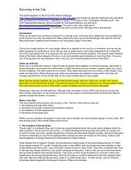
The <strong>farm</strong> barn built by W. H. Dunwoody on<br />
his <strong>farm</strong> in Minnesota is 120' long, 90' wide, 48'<br />
high and cost complete $20,000. The basement<br />
floor is cemented throughout and on it there is<br />
a poultry house 10' x 25' with a glass front to<br />
south, nesting boxes, with inclines, roosts and<br />
runway to outside yard. There also is a storage<br />
THE MODERN BABN.<br />
GENERAL FARM BARNS.<br />
FIG 5—A MINNESOTA FARM BARN (ELEVATION)<br />
8' to 12' wide. They may be double and their<br />
upper ends fold down to admit <strong>of</strong> swinging<br />
under the ro<strong>of</strong>. Turn these doors away from<br />
direction <strong>of</strong> wind. Vertical siding is strongest<br />
and best <strong>for</strong> this frame. Ho<strong>of</strong> projection should<br />
be 2' at gables and generous at eaves. It is best<br />
added at eaves by spiking on sides <strong>of</strong> rafters<br />
short pieces <strong>of</strong> 2" x4", giving the same slope as<br />
the top part <strong>of</strong> the ro<strong>of</strong>. Shingle this clear up.<br />
Do not attempt to bend the shingles. Use galvanized<br />
shingle nails. Do not leave out any<br />
braces. Put 2" blocks on stones under end <strong>of</strong><br />
posts. When they decay they can be replaced<br />
and no injury to posts result.<br />
room 12' x 20' in the west end <strong>of</strong> the basement,<br />
together with an old pump room and wash room<br />
] 0' x 25' ; west stairway to main floor ; three boxstalls<br />
12' x 17' <strong>for</strong> dairy <strong>cattle</strong> ; six stalls <strong>for</strong> dairy<br />
cows; five horse stalls and two box-stalls 8' x 12'<br />
<strong>for</strong> horses ; two rows <strong>of</strong> box-stalls 9' x 12' (six<br />
stalls to the row) with alleys between; 12<br />
19
20 FARM BUILDINGS.<br />
double tie-up stalls 5' 8" long, mangers 26",<br />
width <strong>of</strong> stall 8' 9", each stall being equipped<br />
with iron enamel water bowl, with drop cover,<br />
piped to water supply; drain trenches behind or<br />
connected with all stalls, 18" wide by Sy 2 " deep;<br />
large ventilating flues from basement to attic <strong>of</strong><br />
barn ; the height <strong>of</strong> the basement on north side <strong>of</strong><br />
barn is 4' above outside grade, giving large basement<br />
windows <strong>for</strong> admission <strong>of</strong> fresh air; hand<br />
extinguishers throughout barn and fire hose on<br />
reels, connected to attic tanks; root boiler room<br />
10' x 15', containing large root cooker; masonry<br />
on all sides; steel ro<strong>of</strong>; window <strong>for</strong> fuel; root<br />
r<br />
&MJ.£ V'£ v" J-rj*it\j<br />
QouS*. £ /f<br />
Y fy* $**n
<strong>of</strong> the barn on the driveway leading to the east<br />
end <strong>of</strong> the barn. (See Fig. 7.)<br />
LOVEJOY'S FARM BARN.<br />
The <strong>general</strong>-purpose barn shown in Figs. 8, 10<br />
and 11 was designed by Mt. A. J. Lovejoy and<br />
built on his Riverside <strong>Farm</strong> in Winnebago Co.,<br />
111., in 1903. It is <strong>for</strong> horses and <strong>cattle</strong>, together<br />
with machinery, wagons, manure spreader, car-<br />
riages, buggies and sleighs. It also has bins <strong>for</strong><br />
5,000 bushels <strong>of</strong> small grain, mow room <strong>for</strong> hay,<br />
shredded fodder, a large amount <strong>of</strong> straw and<br />
large tank <strong>of</strong> water which supplies the barn and<br />
adjoining yards. It is 96' x 64' and is built in a<br />
first-class manner, having a joist frame made <strong>of</strong><br />
the best grade <strong>of</strong> hemlock lumber, with Wisconsin<br />
white pine siding and 2" x 6" studding, on which<br />
rosin paper is used and the whole sheathed with<br />
best kiln-dried dressed yellow pine, making an<br />
interior finish equal to many houses. The foundation<br />
is made <strong>of</strong> concrete, from screened gravel<br />
and Portland cement. Every post in the building<br />
rests on solid concrete piers set in the ground<br />
3', on a 4' base. The entire floor is <strong>of</strong> concrete,<br />
8" thick on a gravel fill <strong>of</strong> 15", and was made<br />
with a good finish by an expert builder <strong>of</strong> concrete<br />
sidewalks. The approaches to each door<br />
are also concrete and a concrete sidewalk extends<br />
along the south side <strong>of</strong> the building to the door<br />
<strong>of</strong> the engine room. The inside is divided into<br />
suitable rooms, as shown in the plan. The engine<br />
room is closed so as to exclude dust or dirt from<br />
the mill room. A 12-horse power gasoline engine<br />
furnishes power enough to run the grinder, feed<br />
cutter, sheller, elevator and pump all at the same<br />
time. There is a 28' elevator with a swinging extension<br />
that stands at the side <strong>of</strong> the driveway and<br />
swings behind a wagon while standing on scales.<br />
This elevator will elevate all kinds <strong>of</strong> grain to<br />
the large bins above. These bins have hopper<br />
bottoms with pipes leading to the mill room<br />
GENEBAL FABM BABNS. 21<br />
FIG. 8—LOVEJOY'S FARM BARN (ELEVATION)<br />
below, direct to the grinder, fanning mill and <strong>for</strong><br />
loading wagons. The barn is lighted by acetylene<br />
gas furnished from a plant which also lights the<br />
residence and <strong>farm</strong> <strong>of</strong>fice.<br />
The barn was made <strong>for</strong> convenience in handling<br />
feed and preparing it <strong>for</strong> best results. No<br />
hogs are kept in the barn, but all feed is prepared<br />
in it except the steaming, which is done at the<br />
feed house. All wagons are driven in the barn<br />
and all hitching and unhitching done in it.<br />
The total cost without any <strong>of</strong> the machinery,<br />
engine and the "L" was about $5,000, which<br />
includes painting. The 26' x 100' "L" was<br />
.00.1 ELEVATION<br />
FIG. 9—LOVEJOY'S FARM BARN (FRONT ELEVATION).<br />
joined to the barn <strong>for</strong> a <strong>cattle</strong> shed and has<br />
arched openings that can be closed by roller doors.<br />
Where the diagram is marked "plat<strong>for</strong>m grain<br />
dump" a set <strong>of</strong> scales was put in and an elevator<br />
installed to carry grain to the granary upstairs.<br />
The six large hopper-bottom grain bins are on<br />
the second floor. (Fig. 11.) The bay <strong>for</strong> hay,<br />
indicated in the illustration, was changed and<br />
floored with cement, the same as all the rest <strong>of</strong><br />
the barn. The elevator does not require a dump,<br />
as the hopper swings round behind the wagon<br />
and grain is let out into it from the rear end <strong>of</strong><br />
the wagon. Plank floor is laid in the horse stalls
22 FABM BUILDINGS.<br />
FIG. 10—LOVEJOY'S FABM BARN (GROUND PLAN).<br />
FIG. 1 1—LOVHJOY'S FARM BARN (SECOND FLOOR)<br />
Jxl—tn?:L rTi
on the cement, as it was thought that horses<br />
would be less liable to slip. A drilled well is in<br />
the stable with a 100-barrel tank above in the<br />
second story. A system <strong>of</strong> water works from the<br />
elevated tank in the barn furnishes a good supply<br />
<strong>of</strong> water in the barn and out in the yards.<br />
A better system <strong>of</strong> ventilation is used than the<br />
one shown. All posts in the first story are boxed,<br />
giving a finished appearance. The barn is almost<br />
frost-pro<strong>of</strong> and is very convenient and a com<strong>for</strong>t<br />
to stock housed in it. The front elevation is<br />
shown in Fig. 9. A photographic view <strong>of</strong> the<br />
barn is presented in Fig. 8.<br />
NEW TYPE OF CIRCULAR BARN.<br />
The illustrations (Figs. 12 and 13) show a<br />
circular barn designed by Archiiect Benton Steele<br />
<strong>of</strong> Indiana and erected on a <strong>farm</strong> in that State.<br />
GENEBAL FABM BARNS. 23
24 FABM BUILDINGS.<br />
VriveWay<br />
i<br />
Brick<br />
i<br />
Pavement<br />
IB~J?ErWALif\<br />
Alley<br />
7 tow SVaAls \<br />
X<br />
'/Scales<br />
&\SSAGE \<br />
Closet \<br />
Hay<br />
Chuti<br />
BKICK FLOOR m?M<br />
T lOR<br />
8 COVJ STA L,L3 1<br />
Alcev<br />
jiilEV<br />
/<br />
'RETW/ILL J1<br />
w.c. !j6<br />
SHOWERBATH- *X<br />
^-<br />
\6RAW<br />
/> BOXES<br />
7 FEED<br />
Room<br />
Harnis:<br />
moM Water<br />
Trouoi><br />
ffAXNSSS<br />
ROOM<br />
&£<br />
Covered<br />
MAV6B&<br />
1_<br />
M t^ (-<br />
/<br />
3?<br />
TeedBo* C<br />
V <<br />
5<br />
>v<br />
^<br />
H*<br />
ALLEY Slioiko Door's~&<br />
S\<br />
-\<br />
Box- Stalls EORhfOR. ES<br />
Office<br />
FOR<br />
HERDSMEN<br />
-/oo-o-<br />
fig. 14—an experiment station barn (ground plan)<br />
ARCHOR& Second TIoor Plan<br />
*«•""<br />
ye*'<br />
J<br />
ff-»- -*-£<br />
V<br />
-32 -O-<br />
Carriage «^ Implement room<br />
D<br />
8<br />
I ffi55/R*a»l ny Office ^BEDffoon i<br />
T=T ^ M ^<br />
FIG. 15—AN EXPERIMENT STATION BARN (SECOND FLOOR).<br />
T=^<br />
/=<br />
Seed room<br />
->E
tions with the exception <strong>of</strong> the crib and mills,<br />
as be<strong>for</strong>e mentioned. The ro<strong>of</strong> is entirely selfsupporting,<br />
no trusses being employed, nothing<br />
heavier than 2" x 6" rafters. The mow floor has<br />
an estimated hay capacity <strong>of</strong> 350 to 400 tons.<br />
The haying outfit consists <strong>of</strong> a circular track suspended<br />
about midway up> the span <strong>of</strong> the ro<strong>of</strong><br />
and operates an ordinary swivel car or carrier,<br />
in other ways much the same as in ordinary rectangular<br />
<strong>barns</strong> with straight-away track.<br />
AN EXPERIMENT STATION BARN.<br />
The Iowa Experiment Station barn at Ames<br />
is a very modern affair, roomy and well arranged.<br />
It is a brick veneer, three stories high, 50' x 100'.<br />
The first or ground floor is <strong>for</strong> stock, the second<br />
<strong>for</strong> grain, implements, carriages and the like,<br />
while the third is the hay mow. The silo is <strong>of</strong><br />
brick, has a 4" dead air space in the wall and is<br />
18' in diameter by 28' deep, giving a capacity <strong>of</strong><br />
70 tons. The root cellar, which is under the<br />
driveway, also has a hollow wall. In the horse<br />
stalls a 3" false floor, with wide cracks to allow<br />
urine to drain away quickly, is laid over the<br />
cement, which is the flooring <strong>of</strong> the <strong>cattle</strong> stalls,<br />
all passages being brick-paved. Over those parts<br />
marked A, which are ceiled up 3', there is a wire<br />
network 24" high. That in front <strong>of</strong> the horse<br />
stalls is hinged so that all the feeding may be<br />
done from the alley. The box-stalls <strong>for</strong> horses<br />
are sided up 5' with 2" stuff and iron rods run<br />
the rest <strong>of</strong> the way to the ceiling. (See Figs.<br />
14 and 15.)<br />
In the feed-room the hay and straw are brought<br />
from the third floor in chutes with doors at the<br />
bottom. The grain is also brought down in small<br />
chutes with cut-<strong>of</strong>fs, so that all the mixing <strong>of</strong><br />
feeds may be done on the first floor. A hot water<br />
stove in the herdsman's <strong>of</strong>fice heats the bathroom<br />
and the teamsters' rooms above on the second<br />
GENERAL FARM BABNS. 25<br />
FIO 16—A STOCK AND HAY BABN (FRONT ELEVATION).<br />
floor and also the seed-corn room. The 18"<br />
retaining walls on the southwest corner and north<br />
side show the difference in the elevation, the<br />
ground on the west being higher than that on the<br />
east <strong>of</strong> these walls. On the second floor are the<br />
bedrooms and <strong>of</strong>fice <strong>of</strong> attendants. In the cornroom<br />
there are racks all around so the seed corn<br />
can be ricked or corded, up in them, giving better<br />
ventilation and economizing space.<br />
The driveway is covered and is roughly paved<br />
to give horses a foothold in drawing loads over<br />
it. A continuous chute from top <strong>of</strong> silo permits<br />
silage to be thrown from either <strong>of</strong> the three doors<br />
to the feeding floor. The motor-room just <strong>of</strong>f<br />
the blanket-room is <strong>for</strong> a 15-horse power electric<br />
motor. A line shaft from here into the feed<br />
grinding room allows <strong>for</strong> belting to feed cutters<br />
and other machinery. All the feed-bins have<br />
sloping bottoms to facilitate the passage <strong>of</strong> grain<br />
through the chutes to the mixing-room.' Venti-<br />
lator courses from the ground floor to the outlets<br />
on top give ample ventilation. A stand pipe and<br />
fire hose on reels af<strong>for</strong>d partial protection from<br />
fire within, while larger hydrants outside have<br />
been placed near the building.<br />
A STOCK AND HAY BARN.<br />
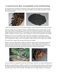
The illustrations (Figs. 16, 17 and 18) are <strong>of</strong><br />
one <strong>of</strong> the most commodious and best arranged<br />
stock and hay <strong>barns</strong> in the West. The building<br />
in the main stands 132' east and west by 112'<br />
north and south and the wings are 32' wide. The<br />
details <strong>of</strong> the basement are very fully shown (Fig.<br />
18) and the conveniences <strong>of</strong> such an arrangement<br />
are obvious. In the basement and immediately<br />
under the wagon floor there are located<br />
three bins <strong>for</strong> grain or ground feed and roots.<br />
They are filled through trap-doors from above,<br />
the sheller, or grinder, or root-cutter, or corncrusher<br />
being placed over the traps and the power
2fi FARM BUILDINGS.<br />
i r 1 r 1 r<br />
Deer 2)rive Why<br />
BTG. 17—A STOCK AND HAY BARN (REAR ELEVATION).<br />
TJZC i<br />
JZE L<br />
0ra/h<br />
I<br />
CeltBox.<br />
^Ji—rX,<br />
o<br />
it<br />
Root Cellar.<br />
-WaterTan/c<br />
/<br />
^.<br />
ffCC<br />
jxa<br />
nn TT<br />
J5ca/f<br />
J26 ineA - / feat, ftia/tf* meaau/vm*&3.<br />
J)nve Way<br />
S<strong>of</strong>ter<br />
r^ i r 1 r
except as otherwise indicated on the diagram.<br />
The water tank is in the center <strong>of</strong> the barn and<br />
large gates expedite the handling <strong>of</strong> the <strong>cattle</strong><br />
back and <strong>for</strong>th from the tank to the stalls, or<br />
1<br />
to the yards if they<br />
are turned out. There are<br />
good-sized box-stalls <strong>for</strong> the service bulls, with<br />
r 1<br />
GENERAL FARM BARNS. 27<br />
direction and the manure loaded onto a wagon<br />
or spreader and carted to the fields. This basement<br />
is surrounded by a stone wall and is very<br />
warm, though amply lighted and ventilated by<br />
numerous windows and doors. The water is<br />
piped underground to the trough from well and
28 FARM BUILDINGS.<br />
FIG. 20b—CATTLE AND HORSE BARN AT WHITEHALL (CONSTRUCTION).<br />
„CATTL,<br />
I ¥_J 1<br />
1<br />
FEED RACK BELOW H HAYRACK QFCCP RACKBELQW g<br />
HAY |3HUT(: ALLEY<br />
HAYRACK >VjTACK<br />
L J<br />
TlffEDgACK BELOW 1~1 HAYRACK FtEPRACJT<br />
FEEPRACK BELOW 1"<br />
X 1 JorATTi^t '5'^' II 15^<br />
"CATTLE"<br />
DftAtrO<br />
DRAIN<br />
CAt I/O IKON HOOO
eserved <strong>for</strong> feed-cutter and <strong>for</strong> hay-rake and<br />
hay-loader and yet additional room in the three<br />
mows <strong>for</strong> 200 tons <strong>of</strong> hay. The capacity <strong>for</strong><br />
grain, including both floors, is from 7,000 to<br />
8,000 bushels. The barn will accommodate 125<br />
head <strong>of</strong> <strong>cattle</strong>, including from 25 to 30 calves.<br />
The building is very substantially constructed<br />
and with due regard to <strong>general</strong> symmetry and<br />
effect. As it stands it is a very attractive building,<br />
well painted and trimmed and cost about<br />
$4,000.<br />
AN INDIANA FARM BAEN.<br />
Fig. 19 shows the ground plan <strong>of</strong> a barn in<br />
which <strong>cattle</strong> and calves may be fed, 20 cows kept<br />
(in Van Norman stalls) and "baby beef" produced.<br />
It is also provided with stalls <strong>for</strong> horses.<br />
The diagram shows how the ground floor is<br />
GENERAL FARM BARNS. 29<br />
basement are <strong>of</strong> sound native whiteoak. The<br />
8" x 12" beams in the drives on the outside are<br />
also <strong>of</strong> whiteoak. All bill stuff and timbers above<br />
the basement are first quality longleaf Southern<br />
pine; 6" x 10" middle tie beams are set back 4"<br />
from face <strong>of</strong> posts to allow studding, which is<br />
2"x4", to pass without cutting. The floor <strong>of</strong><br />
two outside drives is made <strong>of</strong> 2" x 12" oak alternating<br />
with 2" x 3" oak pieces set on edge, all<br />
laid on 8" x 12" whiteoak stringers. The entire<br />
first floor is floored with iy 2 " dressed and<br />
matched yellow pine flooring and the driveways<br />
on the first floor have an upper floor <strong>of</strong> 1"<br />
dressed and matched oak. The entire basement<br />
is ceiled all around the stalls, passages and alleyways<br />
4' high with 1" dressed and matched yellow<br />
pine. The stable doors are built in two<br />
pieces, upper half 3' and the lower half 4' hi h.<br />
TIG. 80d—CATTLE AND HORSE BARN AT WHITEHALL (END ELEVATION).<br />
divided. Fig. 20 shows the arrangement <strong>of</strong> the<br />
second floor. This barn has a cement floor<br />
throughout and is conveniently arranged <strong>for</strong> the<br />
uses to which it is put. Two silos are shown in<br />
one corner, and the corn silage stored in them<br />
is very successfully used in the making <strong>of</strong> "baby<br />
beef."<br />
CATTLE AND HORSE BAEN AT WHITE-<br />
HALL.<br />
Figs. 20a, 20b, 20c, 20d and 20e show the<br />
elevation, floor and other <strong>plans</strong> <strong>of</strong> the beef <strong>cattle</strong><br />
and horse barn which E. S. Kelly recently built<br />
on his Whitehall <strong>farm</strong> in Ohio. Fig. 20c shows<br />
the ground floor on which there are .<br />
stalls <strong>for</strong><br />
<strong>cattle</strong> and horses. All the stone work is <strong>of</strong> good<br />
native limestone, laid up in good lime and sand<br />
mortar. The retaining walls around the drives<br />
have half cement and half lime in the mortar.<br />
All the bill stuff and dimension lumber in the<br />
The ro<strong>of</strong> <strong>of</strong> the Whitehall barn and ventilators<br />
are covered with the best quality 16" cedar or<br />
cypress shingles. The entire barn is framed to<br />
secure the greatest strength and permanency <strong>of</strong><br />
shape with the least weakening <strong>of</strong> timbers. The<br />
windows in the basement are arranged to slide<br />
sideways, as directed. The entire outside <strong>of</strong> the<br />
barn is covered with 4" 'drop siding. The <strong>cattle</strong><br />
floors are made <strong>of</strong> cement. The barn cost about<br />
$7,000.<br />
A WISCONSIN FAEM BAEN.<br />
J. W. Martin's Wisconsin barn shown in Figs.<br />
21, 22 and 23 has a stone wall foundation 20"<br />
high; the first story 8' is double-boarded with<br />
paper between and shiplap floor above. Fig. 22<br />
shows the arrangement <strong>of</strong> the interior and Fig.<br />
23 the plan <strong>of</strong> construction. The approaches to<br />
the main driveway and end doors are paved with<br />
cement. Box-stalls occupy the entire first floor
30 FARM BUILDINGS.<br />
<strong>of</strong> the barn, and one stall<br />
less bull.<br />
is cemented <strong>for</strong> a rest-<br />
The cow barn (Fig. 21) is 30' x 80' with Bidwell<br />
stalls and a driveway between the rows <strong>of</strong><br />
cow stalls on through the middle. This barn<br />
would be more convenient if it were 34' wide.<br />
A KENTUCKY FARM BARN.<br />
The <strong>general</strong> description and plan (Figs. 24,<br />
25 and 26) herewith given are <strong>of</strong> a Kentucky<br />
FIRST FLOOR PIAN<br />
barn built a decade ago. It is a, bank barn anstands<br />
on high ground where natural drainage it<br />
good. The size is 62' x 74', and from basement<br />
1<br />
floor to the<br />
TIG. We—CATTLE AND HORSE BABN AT WHITEHALL.<br />
wind-engine tower the height is 56',<br />
divided into four stories. The basement wall is<br />
<strong>of</strong> limestone, 22" wide and 8' high, and the posts<br />
in the basement supporting the frame work are<br />
twentv in number and are <strong>of</strong> oak, 12" x 12". The<br />
parts <strong>of</strong> the frame are 10" x 10", 16' high. The<br />
entire framework is <strong>of</strong> oak, the shingles <strong>of</strong> poplar
and the siding <strong>of</strong> Northern pine. There were<br />
used in the structure 100,000 feet <strong>of</strong> lumber and<br />
50,000 shingles, and the total cost was about<br />
FIG. 22—A WISCONSIN FARM BARN (GROUND PLAN)<br />
$3,900. The diagrams <strong>of</strong> basement and main<br />
floor (Figs. 25 and 26) are quite complete and<br />
need but little explanation. There are two feed<br />
GENEBAL FABM BABNS. 31<br />
with a cross aisle and <strong>for</strong>ty box-<br />
stalls <strong>for</strong> grown animals, and the cross<br />
or calf aisle will accommodate fifty calves.<br />
The feed descends through a chute from<br />
the third story and two cars await to carry it<br />
FIG. 24—A KENTUCKY FARM BARN (ELEVATION).<br />
The floor <strong>of</strong> this story is double, with pitched<br />
felt between, which protects the animals below<br />
from the ones above. This floor is inclined each<br />
way from the center sufficiently to cause proper<br />
drainage. The entrance to this story is through<br />
double doors, 14' high (Fig. 24), via an elevated
32 FABM BUILDINGS.<br />
macadamized drive extending outward from each, out at the opposite door. A gigantic hay-lift<br />
are placed at one door, so that the grain<br />
is weighed by the wagon load as it is taken from<br />
reaches down from above, takes up a load <strong>of</strong> hay<br />
and puts it in any desired part <strong>of</strong> the third and<br />
the barn. The wagon passes along the aisle and<br />
. Scales
fourth stories or hay l<strong>of</strong>t, which l<strong>of</strong>t has a<br />
capacity <strong>of</strong> 500 bales. The second story has<br />
fourteen calving stalls, as shown in diagram,<br />
which are so arranged that they can readily be<br />
converted in case <strong>of</strong> necessity into four stalls<br />
each, making room <strong>for</strong> 56 cows. In the center or<br />
main aisle, 12' wide, there is room <strong>for</strong> 50 calves.'<br />
This gives the barn a capacity <strong>of</strong> 196 animals,<br />
all sizes. There also is an <strong>of</strong>fice on the second<br />
E*R.m bank.<br />
j^cissyoMsJj;<br />
• •.-••-.-: rr ••:•. ~ ;•• . * a'sffSfZ'/fxi'<br />
i<br />
34 IBM BUILDINGS.<br />
Cor/i<br />
Mi/SJF'eed<br />
Oate<br />
2^'<br />
WIG. 30—A BASEMENT BARN AND CARRIAGE HOUSE (ELEVATION)<br />
% Cows<br />
a'x/4-'<br />
Sta/rch/o/iS<br />
/3'x r'<br />
/0 'X/4 //owe t>f&6/e<br />
FIG. 31—A EASEMENT BARN AND CARRIAGE HOUSE (BASE-<br />
MENT PLAN).<br />
*<br />
V<br />
\<br />
r<br />
24-'<br />
24-'X/2'6'<br />
/V /Y /V<br />
Carr/agTes<br />
24 'X V2'<br />
FIG. 32—A BASEMENT BARN AND CARRIAGE HOUSE (MAIN<br />
ELOOR PLAN)<br />
v,<br />
^
is<br />
in<br />
complete by opening^Indows on three sides,<br />
warm weather and the transom over the<br />
entrance at head <strong>of</strong> stairway. In the<br />
warm air passes up a ventilating shaft<br />
winter<br />
to the<br />
ventilator on top <strong>of</strong> the ro<strong>of</strong>. The granary is set<br />
up from the floor one foot and out from walls<br />
a foot, so it is dry and rat-pro<strong>of</strong>. It and the<br />
bedding-room occupy the back part <strong>of</strong> the basement,<br />
leaving the front part nearest the light and<br />
Sunshine <strong>for</strong> the horse and cow stalls. The horse<br />
stalls are 4' 6" x 12'. The partitions <strong>of</strong> 1" oak<br />
are set into the posts, so there are no nails or<br />
bolts to injure horses.<br />
The hay raxsks are perpendicular, with rounds<br />
3' long set 4 apart. The back <strong>of</strong> the racks is<br />
boarded tight, sloping, leaving a space <strong>of</strong> 6" <strong>for</strong><br />
hay at the bottom and 18" at the top, being<br />
filled from the trap-doors in the hallway on first<br />
floor. The stall on the east side is 1' wider than<br />
the other two to make more room <strong>for</strong> passing<br />
from the feed way into the stable. The bedding-room<br />
opens into the stable behind the<br />
horses and is filled from trap-door at the right <strong>of</strong><br />
carriage entrance on first floor. The granary is<br />
divided <strong>for</strong> corn, oats and mill feed and a drop<br />
door at the bottom <strong>of</strong> each, so feed is removed<br />
and the doors always closed to keep out rats.<br />
The cow stable is fitted with stanchions and a<br />
drop 6" deep and 4' 6" back. The litter from<br />
horse stalls is pressed into the drop to absorb<br />
the moisture from cows and in front <strong>of</strong> the cow<br />
stable stands a low-down manure truck, which is<br />
removed to the meadows or fields when filled.<br />
At the head <strong>of</strong> the feed-room is a water faucet<br />
connecting with a cistern on the bank to which<br />
the water from the ro<strong>of</strong> is piped. There is also<br />
a trough <strong>of</strong> spring water in the barn lot.<br />
The front elevation is shown in Fig. 30. The<br />
double doors to the right open into the carriageroom.<br />
The double doors on the left open into<br />
the shop, which is fitted up with bench, vise, toolcases,<br />
and so on, and lighted by two windows<br />
opposite the doors. The central door enters the<br />
hall to the hay-mow and the stairway into the<br />
basement. Into it hay falls from the mow at the<br />
far end and is put into the racks through trapdoors<br />
that fall back against the partition. In<br />
warm weather these trap-doors are kept open.<br />
In cold weather they are closed down.<br />
The plan <strong>of</strong> first floor, as well as that <strong>of</strong> the<br />
basement, is drawn to a scale <strong>of</strong> one-eighth inch<br />
to the foot. (See Figs. 31 and 33.)<br />
A—Double door 8' x 8' 9" to carriage-room ; B<br />
—Single door 6' x 3' 3" and transom 3' 3" by<br />
14" • c—Double door T x 8' to shop ;D—(Hallway<br />
5' 6" by 24' ; E—Trap-door <strong>for</strong> bedding below; F<br />
—Trap-door <strong>for</strong> feed to granary below; 6<br />
Stairway to basement ; I—Ladder to hay-mow ; J<br />
—Entrance to cow stable ; K—Entrance to horse<br />
GENERAL FARM BARNS. 35<br />
stable; L—Water faucet; N—Trap-doors to hayracks<br />
below.<br />
The building is covered with best pine shin-<br />
gles, weather-boarded with dressed lumber, battened<br />
and painted. The corner posts are 14'<br />
6" x 6". The floors to shop and carriage-room<br />
are 1*4" sycamore and the floor to hay-mow is<br />
tongued and grooved pine flooring with no knot-<br />
holes.<br />
A KENTUCKY STOCK BARN.<br />
The drawings (Figs. 33 and 34) are <strong>of</strong> a Kentucky<br />
stock barn 20' wide surrounding a feed-<br />
FIQ. 33—A KENTUCKY STOCK BARN (MOW PLAN).<br />
JTG. 34—A KENTUCKY STOCK BARN (CROUP PLAN).<br />
lot 100' in diameter. The feed-shed with trough<br />
and rack next to wall has the south side open to
36 FABM BUILDINGS.<br />
the feed-lot. The barn has a sheep department,<br />
hay-rack next to the outside wall and small stalls<br />
<strong>for</strong> ewes and young lambs. It also is provided<br />
with stalls <strong>for</strong> milch cows and calves, boxes <strong>for</strong><br />
bran and crushed corn and box-stalls <strong>for</strong> horses;<br />
there is an 8' unboxed passage outside and a l<strong>of</strong>t<br />
over all except the scales and gateway, which are<br />
open <strong>for</strong> hoisting hay with <strong>for</strong>k on an endless<br />
track. In this l<strong>of</strong>t there is room to store shredded<br />
corn and different kinds <strong>of</strong> hay. A crib . should<br />
be made separate and rat-pro<strong>of</strong>.<br />
A SMALL STOCK BARN.<br />
The barn shown in Figs. 35 and 36 is designed<br />
to hold 50 tons <strong>of</strong> hay, to have six horse stalls,<br />
6' wide, three cow stalls, two box-stalls and a
the side. A A are ends <strong>of</strong> the tie shown in Fig.<br />
37. At the lower piece <strong>of</strong> plate is shown cut<br />
away to show the block, 2" x 8", 3' long, that<br />
rests on top <strong>of</strong> the post and on which the plate<br />
splices, as at 8 S. B B are blocks put in to fill<br />
the post where the braces come against it. Nail-<br />
HOXSESTALL<br />
9FT WIDE<br />
SHEO I6XS3<br />
MAN PER fl/ff — FEEDING CATTLEIN SHED<br />
a „<br />
feed alley & ft wide<br />
OOUBLE<br />
HORSESTALL<br />
OOCaLE<br />
HORSE STALLS<br />
3FT. WIDE<br />
6ATE<br />
COIV •s taOls<br />
DRIVE WAY<br />
T<br />
com<br />
FEED ALLEY<br />
GENERAL FABM BABNS. 37<br />
ILLS<br />
PIG. 40—PLAN FOR A SMALL BARN.<br />
DOOR<br />
girts are 2" x 8" spiked on 4' apart, not shown<br />
in the cut. The tie T splices at S. This tie is<br />
double, breaking the joints. Posts are <strong>of</strong> two<br />
pieces 2" x 10".<br />
The frame is put together with y2 " carriage<br />
bolts and 40-penny spikes. The track <strong>for</strong> the<br />
carrier runs under the peak and the draughts<br />
are run in as soon as they clear the level <strong>of</strong> the<br />
hay in the mow. Slings also carry in bound<br />
grain.<br />
PLAN FOE A SMALL BAEN.<br />
Fig. 40 shows a barn with four double horse<br />
stalls, one box-stall and room <strong>for</strong> 30 cows and<br />
20 other <strong>cattle</strong>. It is seldom satisfactory to<br />
K<br />
combine a horse and cow bam, as the latter can<br />
be more economically built by making it only 30'<br />
wide, but this does not suit so well <strong>for</strong> the horse<br />
1<br />
stalls. If one<br />
could dispense with the driveway<br />
it would be better to cut <strong>of</strong>f as much as needed<br />
<strong>for</strong> the horse stable and place the stalls across<br />
the building with entry from the outside to each<br />
double stall. The oats bin should be placed overhead,<br />
so that oats can be drawn down through a<br />
spout near the horse stalls. This barn with high<br />
curb ro<strong>of</strong> will hold about 60 tons <strong>of</strong> hay.<br />
GOOD TYPE OF FABM BAEN.<br />
The plan illustrated in Fig. 39 shows a <strong>cattle</strong><br />
barn which is 96' x 48'. It is a pole barn with<br />
posts 20' high and a corncrib 80' x 12' runs<br />
through the center <strong>of</strong> the barn ; the lower boards<br />
TIG. 39—GOOD TYPE OP FARM BARN (BLBVATION).<br />
<strong>of</strong> the crib are hinged and feed boxes built on<br />
level with the crib bottom so as to make practically<br />
a selfrfeeder, especially when feeding<br />
shelled corn. Hay-racks on the sides are 80'<br />
long. Hay is put in at the ends <strong>of</strong> the barn.<br />
Sliding doors, controlled by weights, are used at
38 FARM BUILDINGS.<br />
the ends <strong>of</strong> the mow. They are closed when the<br />
hay is in the mow. There are doors alongside<br />
<strong>of</strong> the hay mow. When filling the mow a space<br />
<strong>of</strong> 4' between the hay and the sides df the barn<br />
may be left so that hay may be thrown into the<br />
racks when feeding. The south end is open ; the<br />
north end has doors which are closed in bad<br />
weather. This barn will easily accommodate 100<br />
<strong>cattle</strong>.<br />
BARN FOE SMALL FARM.<br />
A transverse driveway in a barn is rather a<br />
waste <strong>of</strong> space, as. it usually shelters only the<br />
<strong>farm</strong> wagon, yet it is <strong>of</strong>ten desired and in this<br />
plan (Fig. 41) it is made to do duty as a feed<br />
alley. There are stalls <strong>for</strong> four horses and five<br />
cows and a large mow reaching to the<br />
ground and granaries over the drive on each<br />
side, where they are readily filled by hoisting the<br />
grain with a hay-carrier rope. Where ro<strong>of</strong>s are<br />
40' wide or more there should be the truss method<br />
<strong>of</strong> framing rafters, using 2" x 4" brace beneath<br />
the angle, fastened by short pieces <strong>of</strong> 1" x 4".<br />
This truss must be on both sides <strong>of</strong> the ro<strong>of</strong>; it<br />
is shown on one side only in the diagram.<br />
BARN FOR HORSES AND RANGE<br />
CATTLE.<br />
This barn (Figs. 46 and 47) was erected in<br />
Wyoming to shelter pure-bred and range <strong>cattle</strong><br />
f ]i ii 1 1 1 1 1 1 1 i i iHs?Mls>Si 1 1 1 1 m'fi 1 1 I'll f '<br />
i f 1<br />
1 1 1 1<br />
I It H EQO '** 1 1<br />
KajEtSSssl w 1 li IXQJ rtTii<br />
PIG. 46—BABN FOR HORSES AND RANGE CATTLE (SIDE<br />
ELEVATION).<br />
and horses. The long shed is open on one side<br />
next the yard and <strong>for</strong>ms a good windbreak. The<br />
end <strong>of</strong> this shed is shown to right <strong>of</strong> cut <strong>of</strong> the<br />
~IL_
is a hay track and where hay comes directly to<br />
the earth. Well braced this building will keep<br />
its shape <strong>for</strong> many years.<br />
THE GLIDE UMBKELLA BAEN.<br />
In the Sacramento Valley <strong>of</strong> Cali<strong>for</strong>nia there<br />
is little cold weather but some rain in winter. A<br />
Mr. Glide has there built an immense barn with<br />
a ro<strong>of</strong> projecting about 12' on every side, beneath<br />
which <strong>cattle</strong> shelter and eat hay stored within.<br />
The ideal location <strong>for</strong> the barn should be as<br />
nearly as possible in the center <strong>of</strong> the <strong>farm</strong>. The<br />
dwelling <strong>of</strong> course must be near. The advan r<br />
tage <strong>of</strong> having as many pastures and fields<br />
directly connecting with the <strong>barns</strong> is obvious.<br />
Time, distance, labor, all are saved, and oversight,<br />
at all seasons, <strong>of</strong> the stock made more<br />
convenient. The character <strong>of</strong> the site, however,<br />
is <strong>of</strong> still greater importance, and perhaps there<br />
is nothing worse than a low, flat, undrained barnyard<br />
and adjacent lots. Strange to say, however,<br />
nothing is more common.<br />
If such a location is unavoidable then it will<br />
pay to use all the resources <strong>of</strong> drainage, tile and<br />
stone, till even the longest wet spell loses its<br />
terrors and planks and rails no longer are needed<br />
as bridges to cross th'e depths and reach the barn<br />
door. Wet, and not cold, is the greatest enemy to<br />
thrift and flesh, and the floors <strong>of</strong> all sheds and<br />
pens should be high, dry and well drained. The<br />
importance <strong>of</strong> a sufficient number <strong>of</strong> well fenced,<br />
conveniently arranged lots <strong>of</strong> sizes from a hundred<br />
or so square feet up to an acre or two should<br />
not be overlooked. There are never too many.<br />
There is an infinite variety <strong>of</strong> wants met by an<br />
infinite variety <strong>of</strong> circumstances, mental pecu-<br />
liarities and financial conditions, resulting in acorresponding<br />
variety <strong>of</strong> <strong>farm</strong> <strong>buildings</strong>.<br />
Good air, good light and dryness are <strong>for</strong>emost<br />
in importance; they go together. One <strong>of</strong> these<br />
qualities lacking, the others are almost sure to<br />
be absent. The dark, cavernous recesses <strong>of</strong> very<br />
large <strong>barns</strong> are seldom ventilated or dry. The<br />
heavy foundations imply a basement dark, damp<br />
and malodorous. The great ro<strong>of</strong> and floors mean<br />
heavy timbers, much skilled labor and expense,<br />
and last but not least is the chance that some<br />
winter night, in red and yellow flame skyward<br />
soaring, the huge structure vanishes with all the<br />
horrors <strong>of</strong> agonizing death to helpless animals<br />
QENEBAL FABM BABNS. 39<br />
CATTLE BARNS.<br />
The idea is worth considering in any warm wet<br />
country. (See Figs. 43, 44 and 45.)<br />
FIG. 45—THE GLIDE UMBRELLA BARN (SIDE VIEW).<br />
and to the owner loss immeasurable. More desirable<br />
are two or more smaller <strong>buildings</strong>, all above<br />
ground, on light foundations, light timbers with<br />
but little framing and far enough apart <strong>for</strong> some<br />
degree <strong>of</strong> safety from fire and a chance to save<br />
life. There should be doors on every side and<br />
ample windows. Nothing is so cheap as sunlight<br />
and yet nothing is so scarce in the average barn<br />
or stable. Another great advantage <strong>of</strong> somewhat<br />
scattered and smaller <strong>buildings</strong> is the possibility<br />
<strong>of</strong> dividing up the stock and obtaining direct<br />
access from different lots and pastures <strong>for</strong> different<br />
classes <strong>of</strong> stock. It is not uncommon to see in<br />
the middle <strong>of</strong> the night, in a large barn, a hundred<br />
<strong>cattle</strong> aroused and disturbed by one uneasy<br />
heifer or lost calf. Avoid all plank flooring as<br />
one <strong>of</strong> the worst temptations <strong>of</strong> the artful architect.<br />
Broken stone (8") with here and there a<br />
3" tile running to the outside, with 6" <strong>of</strong> porous,<br />
yellow clay on top, wetted and tamped, hardening<br />
like a brick, will always be dry, never slippery,<br />
needs only here and there after the winter<br />
is over a little fresh clay and af<strong>for</strong>ds no harbor<br />
<strong>for</strong> rats. Many breeders prefer cement floors,<br />
which are in common use. Have no narrow, contracted<br />
passageways in which the larger <strong>cattle</strong><br />
will crowd and jam together. A favorite arrangement<br />
seems to be a narrow feeding alley, two<br />
rows <strong>of</strong> <strong>cattle</strong>, heads in, and two narrow passageways<br />
behind the <strong>cattle</strong>. This is a. misuse <strong>of</strong> space,<br />
more expensive and no more convenient. Ear<br />
better have one wide space, not less than 10',<br />
which is less than the 3' in the center, in which<br />
the <strong>cattle</strong> have ample room to walk quietly to<br />
their stalls, Where they stand heads to the wall.<br />
A hand-cart may be used to distribute the feed<br />
(be<strong>for</strong>e the <strong>cattle</strong> come in at night) and every<br />
animal always has the same stall. A noted <strong>cattle</strong><br />
breeder is quoted as saying that time and again<br />
he has seen 70 head <strong>of</strong> cows walk into such a
40 FARM BUILDINGS.<br />
stable from three entrances and -be tied up by<br />
two men and munching their feed in 20 minutes,<br />
with neither noise, hurry nor confusion.<br />
Every barn should have a mow sufficient at<br />
least to supply its inmates with the winter's hay,<br />
bins <strong>for</strong> bran and prepared feed, but it is the<br />
opinion <strong>of</strong> many <strong>farm</strong>ers that the corncribs<br />
should be separate and distinct structures.<br />
In latitudes where the mercury only now and<br />
then falls below zero animals suffer more from<br />
the barn being too warm and close than from<br />
cold. In fact but <strong>for</strong> the difficulty <strong>of</strong> properly<br />
apportioning feed, so far as health is concerned,<br />
a good, deep shed, say 20' from front to rear,<br />
with a hay-rack and plenty <strong>of</strong> bedding, is better<br />
than a barn; the air is pure; there are no<br />
draughts and no over-heating and no chilling.<br />
Health and vitality are in direct proportion to<br />
pure air and well bedded is half fed.<br />
No matter how perfect the barn may be nothing<br />
can take the place <strong>of</strong> abundant bedding, and<br />
convenience in getting it in and getting it out<br />
(in the shape <strong>of</strong> manure) easily and rapidly is<br />
a thing indispensable. The manure should go<br />
direct from the stalls to the pastures and corn-<br />
fields. As long as wheat will pay the cost <strong>of</strong><br />
production the straw is a .sufficient pr<strong>of</strong>it to<br />
justify the stock raiser in growing it. Sawdust<br />
and even dry leaves are useful if straw is lack-<br />
ing. Water in the barn is not <strong>general</strong>ly a success.<br />
A large central tank supplying drinking<br />
troughs in every lot, fitted with covers to be<br />
closed at night in the winter, seems to serve every<br />
purpose, and it is a rare day when all kinds <strong>of</strong><br />
stock should not be turned out <strong>for</strong> a few hours at<br />
least. Thirsty <strong>cattle</strong> coming suddenly out <strong>of</strong> an<br />
overheated barn may be hurt by drinking ice<br />
water but the cold air has the same effect and<br />
the 'condition <strong>of</strong> the <strong>cattle</strong> is the fault.<br />
Hinges <strong>of</strong> course are obsolete. Nothing but<br />
the best <strong>of</strong> rollers should be used, the track <strong>of</strong><br />
iron, put up as true and solid' as it is possible to<br />
have it, and then watch and keep clean the groove<br />
in which it runs at the bottom. Box-stalls should<br />
be built wherever a ro<strong>of</strong> can be extended along<br />
the sides without cutting <strong>of</strong>f the light and air<br />
from the main building. A long shed closed in<br />
front and divided into box-stalls, on the north<br />
side <strong>of</strong> a lot, is <strong>of</strong> great utility.- One or two<br />
extra warm ones should always be provided a lit-<br />
tle to one side <strong>for</strong> winter-night calving, sick animals<br />
and the like.<br />
Many patent fastenings have been suggested<br />
and advertised, but after all nothing in practice<br />
has been found more convenient, more speedy or<br />
more safe than the old-fashioned German chain<br />
<strong>cattle</strong> tie with about a foot play on a vertical<br />
y2 " iron r°d under the edge <strong>of</strong> the manger.<br />
The <strong>cattle</strong> have perfect freedom up and down<br />
and can reach to the center <strong>of</strong> the manger <strong>of</strong> an<br />
8' or 9' double stall. When taken <strong>of</strong>f the <strong>cattle</strong><br />
the end ring should be hooked over a nail in the<br />
side <strong>of</strong> the stall just above the animal's neck,<br />
where it is just in place <strong>for</strong> use at night.<br />
A KANSAS CATTLE BABN.<br />
, The diagram (Figs. 48 and 49), as will be<br />
seen,- * &' ourrca V/ gutter<br />
FIG. 48—A KANSAS CATTLE BARN (GROUND PLAN).<br />
Kansas. The unpretentious yet admirably<br />
arranged building (briefly described herewith)<br />
was built many years ago and has given the<br />
best <strong>of</strong> satisfaction. The materials used in its<br />
construction were as follows: 32 telegraph poles,<br />
20' long; 32 telegraph poles, 25' long; 6,000' <strong>of</strong><br />
boards, 16' long; 30,000 shingles; 400 battens,<br />
3" x y2 ", 16' long; 34 sashes, 4 lights, 10" x 12"<br />
4,500' <strong>of</strong> flooring; 200 joists, 2" x 8", 16' long;<br />
2,500' <strong>of</strong> rough boards; 250 pieces, 2"x4", 16'<br />
long; 1,400' <strong>of</strong> masonry in underpinning.<br />
TRONT ELEVATION<br />
FIG. 49—A KANSAS CATTLE BARN.<br />
Points in favor <strong>of</strong> this <strong>cattle</strong> barn are cheapness,<br />
light, ventilation and ample room. The<br />
wide alleyway permits the ready and uncrowded<br />
passage <strong>of</strong> <strong>cattle</strong>, and the same is true <strong>of</strong> the<br />
stalls. Wagons go through and take up the<br />
manure, which goes direct to the fields. Bedding<br />
is distributed in the same way, and hay from the<br />
outside is distributed in' this way, holding in<br />
reserve that in the mow. The dirt floor is cheap<br />
and never slippery. The holes which wear are<br />
readily filled by a load or two <strong>of</strong> dry earth which<br />
is at once an absorbent and deodorizer. All the
windows open on one side or the other (to the<br />
leeward) and have no "wheezing" or "coughing."<br />
It was built by two carpenters and four laborers<br />
in thirty days and cost about $1,100. The mow<br />
FIG. 51—THE MORGAN COW BARN (GROUND PLAN).<br />
CATTLE BARNS.<br />
FIG. 50—THE MORGAN COW BARN (FRONT ELEVATION).<br />
holds nearly 140 tons <strong>of</strong> hay by filling up after<br />
the first has settled.<br />
THE MORGAN COW BARN.<br />
The barn shown in Figs. 50 and 51 is T-shaped,<br />
413' across the front and extending back 280'.<br />
It was recently built by F. W. Morgan on his<br />
Wisconsin <strong>farm</strong>. The entire barn covers about<br />
three-quarters <strong>of</strong> an acre. There are two silos in<br />
connection with the barn, the <strong>for</strong>ward one being<br />
25' inside diameter with 18" walls and 40' high<br />
with 8' in ground. The other silo is 30' inside<br />
diameter and 40' high. Both are constructed <strong>of</strong><br />
grout, a mixture <strong>of</strong> four parts ordinary gravel,<br />
two parts sand and one part Portland cement.<br />
These silos have given good satisfaction. The<br />
entire floor <strong>of</strong> the barn is also made <strong>of</strong> grout A<br />
patent ro<strong>of</strong>ing is used in covering both the sides<br />
and ro<strong>of</strong>. This is composed <strong>of</strong> layers <strong>of</strong> felt,<br />
burlap and felt, the three coats being cemented<br />
BOX STALES i<br />
HlwiovABi-E sijoes<br />
SAMf 1<br />
j<br />
together with asphalt. The sides are battened.<br />
The frame is composed <strong>of</strong> 2" x 10", 6" x 6" and<br />
2" x 6" planks and is <strong>of</strong> ordinary construction.<br />
In the center <strong>of</strong> the barn is an open space in<br />
which is a weighing scale and from which silage<br />
can be loaded and carried to feed troughs under<br />
cover. The maternity stable has double rows <strong>of</strong><br />
posts equi-distant apart with grooved sides into<br />
which portable gates can be placed, thereby <strong>for</strong>ming<br />
separate stalls 28' square <strong>for</strong> each cow and<br />
calf. There are eight bull stalls 16' x 25', each<br />
one with separate door into yard.<br />
AN IOWA CATTLE BARN.<br />
The barn shown in Figs. 52 and 53 is 48' x 68'.<br />
It was built in 1893 as a hay, stock and feed<br />
barn, with the hay part in the center 24' x 48',<br />
with a 14' stock driveway on each side and corn-<br />
41
42 FABM BUILDINGS.<br />
cribs 8' x 48' on each side <strong>of</strong> stock-way, with<br />
troughs in the stock-way next to crib and oat-bin<br />
over each stock-way, with chutes leading to<br />
troughs below. As thus arranged the barn holds<br />
3,000 bushels <strong>of</strong> corn, 1,500 bushels <strong>of</strong> oats and<br />
CROUWO PLAN OF CATTLE BARN 41X68<br />
65 tons <strong>of</strong> hay, with feeding room <strong>for</strong> 40 head <strong>of</strong><br />
<strong>cattle</strong>.<br />
In order to increase the stock room and reduce<br />
the hay compartment the center part was<br />
changed into a <strong>cattle</strong>-barn, providing room <strong>for</strong><br />
30 <strong>cattle</strong> in stalls, with the same stock room<br />
outside <strong>of</strong> this as be<strong>for</strong>e. A feed-bin 8' x 6' x 48'<br />
was built, with a chute to stalls below. There is<br />
room <strong>for</strong> 60 <strong>cattle</strong> (20 stalled), 3,000 bushels <strong>of</strong><br />
ear-corn, 1,500 bushels <strong>of</strong> oats, 1,000 bushels <strong>of</strong><br />
shelled corn or ground feed and about 40 tons<br />
<strong>of</strong> hay. The frame is whiteoak poles set in<br />
ground every 8' except at cribs, where they are<br />
4' apart, with additional foundations set on stone<br />
under each crib.<br />
A HAWKEYB CATTLE BARN.<br />
The <strong>cattle</strong> barn shown in Figs. 54 and 55 was<br />
built <strong>for</strong> C. S. Barclay <strong>of</strong> Iowa. The capacity <strong>of</strong><br />
FRONT ELEVATION<br />
FIG. 54—A HAWKEYH CATTLE BARN.<br />
FIGS. 58 AND 53—AN IOWA CATTLE BARN.<br />
the barn figures as follows: Hay, 240 tons;<br />
grain, 9,000 bushels; <strong>cattle</strong>, 100 head; horses, 10<br />
head. The frame is balloon construction and all<br />
<strong>of</strong> native hard-wood, the lumber being sawed on<br />
Mr. Barclay's <strong>farm</strong>. With the exception <strong>of</strong> the<br />
4" x 12" sill there is nothing thicker than 2" in<br />
the frame, the girders, posts and some other members<br />
being built up.<br />
This makes a much stronger job and saves<br />
time in the framing., The back 45' <strong>of</strong> the first<br />
floor is used as the main mow. The bents which<br />
<strong>for</strong>m the frame in this part <strong>of</strong> the barn are so<br />
constructed that no cross-tie beams are required.<br />
This arrangement requires less labor and material<br />
and makes a stronger construction, besides<br />
doing away with the objectionable tie-beams. The<br />
frame is all securely bolted together.<br />
A dump elevator and grinding machinery are<br />
so installed as to save much labor. (See Fig. 57.)<br />
The power required to run the machinery is furnished<br />
by a 12-horse power portable gasoline<br />
engine. Chutes are so arranged that all kinds <strong>of</strong><br />
feed are accessible in the feed room without handling.<br />
A water supply is also installed. (See<br />
Fig. 56.)<br />
The floor in the driveway <strong>of</strong> the basement and<br />
also in part <strong>of</strong> the stalls is <strong>of</strong> paving brick laid<br />
LIFT 9101 CLCVATIOH.<br />
ITIG. 55—HAWKEYE CATTLE BABN.
on a bed <strong>of</strong> sand, the cracks between the bricks<br />
being washed full <strong>of</strong> thin cement. The remainder<br />
<strong>of</strong> the floor in the basement is <strong>of</strong> concrete. The<br />
floor <strong>for</strong> the house stable,<br />
floor, is <strong>of</strong> concrete.<br />
which is on the first<br />
Behind the stalk the concrete is covered with<br />
2" flooring. The stalls are provided with hardwood<br />
gratings, which can be removed <strong>for</strong> cleaning.<br />
The <strong>cattle</strong> mangers and feed-racks are a<br />
new departure. The barn cost about $6,000.<br />
ANOTHER KANSAS CATTLE BARN".<br />
This barn is built <strong>of</strong> joist construction, no<br />
piece being more than 2" thick. It has ample<br />
storage <strong>for</strong> all the <strong>cattle</strong> that can get beneath the<br />
ro<strong>of</strong> and is so constructed that winds have little<br />
effect upon it, the low ro<strong>of</strong> deflecting them harmlessly<br />
upward.<br />
The dimensions are 60' x 112'. It is so<br />
designed, however, that the length may at any<br />
BASEMENT PLAN<br />
BG. 56—HAWKIYE CATTLE BARN.<br />
time be increased by adding more bents. The<br />
principle <strong>of</strong> construction is clearly shown in Pig.<br />
58, an end elevation showing a doorway framed<br />
to take in hay from the outside. This feature is<br />
not in the barn as built.<br />
This barn has the open-center which admits <strong>of</strong><br />
hay being unloaded by slings and carriers that do<br />
not raise the hay higher. than high enough to<br />
CATTLE BABNS. 43<br />
clear the level <strong>of</strong> the top <strong>of</strong> the mow be<strong>for</strong>e<br />
they swing back.<br />
The interior arrangement as adapted to the<br />
feeding <strong>of</strong> young beef <strong>cattle</strong> also is shown in<br />
Fig. 58. The exterior is nicely presented in the<br />
This barn has been extensively copied. It is<br />
unique in that it dispenses with siding except at<br />
the ends, and <strong>for</strong> strength, cheapness and <strong>general</strong><br />
1
44 FABM BUILDINGS.<br />
i<br />
^<br />
i<br />
i<br />
i i<br />
i j<br />
i<br />
i<br />
i<br />
i J<br />
L__h<br />
n<br />
K 1<br />
i<br />
1 I<br />
i
sized and well-drained paddocks, and the fall is<br />
equally good on the west. Fig. 59 shows the rear<br />
(west) elevation, and also the engine-house and<br />
water tank. A large gasoline engine pumps water<br />
and runs corn-sheller, grinder, fodder-shredder<br />
and' hay-cutter on the upper floor. While possibly<br />
a little power may be lost in transmission,<br />
yet the engine is adequate, and this small loss<br />
CATTLE BABN8. 45<br />
FIG. 59—AN INDIANA CATTLE BARN (BEAR ELEVATION).<br />
V N/ W W W \K N^<br />
/ w w w \y w \y<br />
X7^7^S<br />
6 >,& , 6<br />
A FIG.<br />
is more than compensated <strong>for</strong>=by the protection<br />
from fire in this detached engine-house. The<br />
well is equipped with a 6" pipe and the supply<br />
is fairly inexhaustible.* Hot ,and "cold water is. on<br />
tap in the barn, The entrance to the huge upper<br />
60—AN INDIANA CATTLE BARN (FRAMEWORK).<br />
The posts are all set on stone foundations. Pig.<br />
61 gives an idea <strong>of</strong> the framing <strong>of</strong> the barn, showing<br />
an end and an inside bent. The ends are<br />
strongly framed and a very large inside space<br />
is clear. The ground plan is indicated in Fig.<br />
62, which shows the arrangement <strong>of</strong> the stalls. A<br />
row <strong>of</strong> large boxes runs through the. center and<br />
the middle partitions through the entire row are<br />
.movable, so that two boxes may be thrown into<br />
one. On either side the cows with calves" may<br />
be tied, two to a stall, although each stall will<br />
com<strong>for</strong>tably accommodate three cows. The convenience<br />
<strong>of</strong> the calf pens needs no explanation.<br />
1<br />
,<br />
floor <strong>for</strong> hay and corit-fodder is at the corner „ThIs barn is very substantially built but without<br />
nearest the engine-house. ,.<br />
;<br />
,1r -extravagance. It was. designed throughout by<br />
The side <strong>of</strong> the framework is shown in Fig. 60. "f'Mr. Nave as "the most convenient plan that he<br />
FIG. 61—AN INDIANA CATTLE BARN (FRAMEWORK AND FOUNDATION).
46 FABM BUILDINGS.<br />
/<br />
I J)iiin.(«p<br />
fflmn<br />
l<br />
*' *4I » M* i<br />
IT<br />
JwC u-r; ZS" c u~ \<br />
PIG. 62—AN INDIANA CATTLE EARN (GROUND PLOOR PLAN).<br />
PIG. 68—A HOOSIER CATTLE BARN (SIDE ELEVATION).<br />
'<br />
.. .;.vc:<br />
3 (tit ton .iH«i«;<br />
an . 4^<br />
<<br />
3^C=3<br />
^<br />
tal* rt»u.<br />
Oowit —<br />
could figure out <strong>for</strong> the economical care <strong>of</strong> a large The second story will hold all the provender<br />
herd. It will easily accommodate 150 head <strong>of</strong> and <strong>for</strong>age needed <strong>for</strong> a large herd, thus doing<br />
<strong>cattle</strong>, and 200 head may be com<strong>for</strong>tably housed away with the necessity <strong>of</strong> hay <strong>barns</strong> and fodder<br />
without crowding. stacks. In the west end the mill rooms are lo-
cated, and the prepared feed drops below to the<br />
mixing floor.<br />
A HOOSIEB CATTLE BAEN.<br />
Figs. 63 and 64 show the ground plan, interior<br />
arrangement and elevation <strong>of</strong> one <strong>of</strong> the large<br />
<strong>cattle</strong> <strong>barns</strong> on the <strong>farm</strong> <strong>of</strong> J. H. Miller <strong>of</strong> Indiana.<br />
The arrangement <strong>of</strong> this barn is very convenient,<br />
and while it is large and roomy it has<br />
not cost an extravagant amount <strong>of</strong> money. The<br />
advantage <strong>of</strong> the arrangement <strong>of</strong> the different<br />
stalls and paddocks will be readily perceived, and<br />
FEED TROUGH on<br />
CATTLE BABNS.<br />
4" x 4" ; rafters, 2" x 4". and the barn cost about<br />
$2,500.<br />
AN OCTAGONAL CATTLE BARN.<br />
An octagonal barn that will accommodate<br />
about 50 head <strong>of</strong> <strong>cattle</strong> is shown in Pigs. 65 and<br />
66.<br />
The octagonal <strong>for</strong>m has always seemed open to<br />
the objection <strong>of</strong> being hard to fill with hay and<br />
more difficult to arrange in the interior. However,<br />
it may be that the great amount <strong>of</strong> space<br />
secured at the cost <strong>of</strong> a much less amount in the<br />
47
48 FABM BUILDINGS.<br />
ment 8' to 10', the ro<strong>of</strong> will rise 20' and the little<br />
turret in the peak will be about 48' above the<br />
foundation. The ro<strong>of</strong> is self-supporting, the<br />
plates being bolted together at the corners and<br />
held by a band <strong>of</strong> iron 4' long bent to fit and<br />
solidly bolted so that the corners can never spread.<br />
The plates are <strong>of</strong> 2" x 12", two parts. All parts<br />
are <strong>of</strong> joist construction.<br />
The basement plan shows stalls <strong>for</strong> over 60<br />
<strong>cattle</strong>; the larger <strong>cattle</strong> would be in the outer<br />
circle, the smaller ones in the inner row. One<br />
JTG. 68—AN OCTAGONAL CATTLE BARN (ELEVATION).<br />
TIG. 68—AN OCTAGONAL CATTLE MRS (GROUND PLAN).<br />
feeding alley serves <strong>for</strong> the two rows and a circular<br />
track brings<br />
1<br />
in grain or silage and another<br />
circular track and conveyor takes away the<br />
manure. Above the passage and just within the<br />
outer door there will be chutes from above, down<br />
which will come hay, bran and other feed, the<br />
granaries being located there, and filled from the<br />
same door that takes in hay. There would be<br />
other hay chutes leading down to the feed alley.<br />
Abundant light and air are let in to the basement<br />
by a practically continuous window 3' high<br />
and 3' above the ground. The sashes <strong>of</strong> this<br />
window hinge at the bottom edge and incline inward,<br />
each one being opened all at one motion or<br />
closed by a motion, the mechanism being the<br />
familiar contrivance employed in greenhouse construction.<br />
The outer walk is 4' wide at its narrowest<br />
point. Perhaps 3' would be better, as it<br />
would give more room between the <strong>cattle</strong>, and<br />
with the manure conveyors there is not the need<br />
<strong>of</strong> wide passages that there once was. Cement<br />
floor throughout and Van Norman stalls com-<br />
plete the basement construction.<br />
A CO'BJST-BEI/T BAKN".<br />
The Illinois barn illustrated in Figs. 67, ,68<br />
and 69 has an immense storage capacity af<strong>for</strong>ded<br />
<strong>for</strong> hay and straw, and in view <strong>of</strong> the vast quan-<br />
uiiF*Mij, ii 'I lit jmpumiUBaaewW^-<br />
PIG. 67—A CORN-BELT BARN (END SECTION).<br />
tity <strong>of</strong> <strong>for</strong>age <strong>of</strong> that description wasted annually<br />
from lack <strong>of</strong> protection from the inclement<br />
weather the question arises as to whether or not<br />
more attention should be given to that subject<br />
in the construction <strong>of</strong> <strong>barns</strong>.<br />
eoxsml<br />
coir<br />
$*T£<br />
&rf<br />
Cow<br />
MINIMI ton<br />
My 8/ir f/?o/H
ear are two smaller doors wide enough to admit<br />
the straw-carrier <strong>of</strong> a threshing machine, so that<br />
when threshing the machine dumps the straw into<br />
the l<strong>of</strong>t <strong>of</strong> the barn over the stack on either or<br />
both sides by moving the machine, There is also<br />
Cbv*r<br />
CATTLE BABNS. 49<br />
TIG. 70—MODERN TYPE OT CATTLE BARN (ELEVATION).<br />
J*"/<br />
PIG. 71—MODERN TYPE OF CATTLE BARN (GROUND PLAN).<br />
a large door 10' x 9' <strong>for</strong> taking hay from the load<br />
by the horse hay <strong>for</strong>ks on a trade running the<br />
entire length <strong>of</strong> the comb <strong>of</strong> the barn, hauled up<br />
by horse at the other end <strong>of</strong> the barn.<br />
Material <strong>of</strong> the following description is used:<br />
Sills, 6" x 8" ; joists, 2" x 8" ; corner posts, 6" x 6" ;<br />
other posts, 4" x 6" ; braces, 4" x 4" ; girts, 2" x4"<br />
plates, 4" x 6"; rafters, 2" x 4" ; sheeting, second<br />
fencing; shingles, 18", best; siding, 12" stock<br />
boards; flooring,?" x 8".<br />
MODEEN TYPE OF CATTLE BAKN".<br />
A sanitary, com<strong>for</strong>table and commodious barn<br />
recently built is that designed by Joseph E. Wing<br />
<strong>for</strong> H.H. Trimble <strong>of</strong> Iowa. It has 84 single<br />
stalls and 10 box-stalls or breeding pens. There<br />
are bins <strong>for</strong> grain and storage <strong>for</strong> 350 tons <strong>of</strong><br />
<strong>for</strong>age above. Silos may be conveniently added,<br />
one at the end <strong>of</strong> each wing, where the feed-car-<br />
rier will convey the silage down the central alley<br />
between the rows <strong>of</strong> <strong>cattle</strong>.<br />
The barn is 30' wide and <strong>for</strong>ms three sides <strong>of</strong><br />
an open court (Pig. 70), 66' x 78', which is<br />
designed to be paved with vitrified brick or concreted,<br />
having a water tank in center, thus <strong>for</strong>m-
50 FABM BUILDINGS.<br />
ing a convenient sheltered yard where <strong>cattle</strong> may<br />
exercise any day in severe weather. Fig. 71 shows<br />
the ground floor. The specifications provide this<br />
barn with manure-carriers behind the <strong>cattle</strong>, feed<br />
carriers with track in front <strong>of</strong> them and numerous<br />
windows to admit light and air. The windows<br />
are hinged at the lower edge and open<br />
inward with ,greenhouse construction, so that a<br />
MBBT3m$t K|"il"a gljifm |@j S IH ffl;<br />
M p bli_ia|—p|—lap—m—fa|_laM<br />
.: '..J Musi i i ; { ; I L .'...: i [....<br />
JBTG. 74—AN ILLINOIS CATTLE BABN (SIDE ELEVATION).<br />
turn <strong>of</strong> a wheel opens a row <strong>of</strong> them. Sectional<br />
hay chutes extend down into the feed alleys. The<br />
barn has cement floors and Van** Norman stalls.<br />
This barn has proved very satisfactory to the<br />
proprietor, who says that "we believe we have<br />
Pi<br />
"ool<br />
FEED BIN<br />
12X12'<br />
124<br />
about 300 tons <strong>of</strong> hay and there is a place directly<br />
over the meal bin <strong>for</strong> two carloads <strong>of</strong> bran or<br />
feed. One floor <strong>of</strong> the barn is cement, having<br />
a slope <strong>of</strong> 5" from where the cows are chained<br />
in the box-stalls. The stalls also slope 2" from<br />
FIG. 72—A BABN FOB BBEEDING CATTLE (END ELEVATION).<br />
outside the barn to the drain behind the cows.<br />
The drain slopes gradually from both ends toward<br />
the center, where there is a till to receive<br />
the liquid. There are six large ventilators running<br />
from the bottom <strong>of</strong> the barn up to the
erage in the <strong>barns</strong> and yards and there are water<br />
troughs in every yard that drain directly into the<br />
sewer, so that when hot in use they can be<br />
iSECTION SHOWING FRAMING<br />
or INTERIOR BAYS<br />
iSrCTJOH SHOWING FRAMING<br />
OrijABLf fNDi<br />
FIG. 75—ILLINOIS CATTLE BARN (SECTION).<br />
fl|£<br />
i na<br />
i; n<br />
na<br />
i4'iu' 156 i2ir<br />
7fT"~<br />
at<br />
14'<br />
as<br />
14'<br />
i FIRST FLOOR PLAN i FOUNDATION PLAN<br />
PIG. 76—ILLINOIS CATTLE BARN (PLAN).<br />
drained, thereby obviating the danger <strong>of</strong> freezing<br />
and insuring water <strong>of</strong> even temperature at all<br />
times.<br />
The dimensions <strong>of</strong> this barn are 71' 8" x 121'-<br />
CA1TLE BABNS.' 51<br />
10". The diagrams shown in Pigs. 74, 75 and 76<br />
present a clear idea <strong>of</strong> its arrangement.<br />
Peed is conveyed by trolley cars on either side<br />
<strong>of</strong> the main floor and in front <strong>of</strong> the <strong>cattle</strong> stalls.<br />
The capacity <strong>of</strong> the hay l<strong>of</strong>t is 260 tons. The<br />
hay is taken up in the center <strong>of</strong> the barn and conveyed<br />
by reversible carriers to either end <strong>of</strong> the<br />
barn and is thrown down in center <strong>of</strong> main floor<br />
to feed <strong>cattle</strong> in the stalls. The racks in the<br />
box-stalls are filled directly from the l<strong>of</strong>t through<br />
trap doors in the floor which may be closed when<br />
not in use. Alleys behind the stalls are wide<br />
enough so that a manure spreader <strong>for</strong> receiving<br />
the manure may be driven through and taken<br />
directly to the fields.<br />
AN OPEN CENTEK CATTLE BAEN.<br />
The <strong>cattle</strong> barn shown herewith is 50' x 105'<br />
with a basement 10' high and second floor posts •
52 FARM BUILDINGS<br />
are in their stalls. The stalls may be put further<br />
apart than they are if it is not thought best to<br />
turn the <strong>cattle</strong> into the yard while the stable<br />
is being cleaned. The stalls are 3y2 ' apart, thus<br />
getting 14 animals in a row. The whole barn<br />
may be divided in this way or part <strong>of</strong> it may be<br />
made into pens in which polled or dehorned <strong>cattle</strong><br />
may run loose.<br />
W/Uk<br />
-— w— 1
accuracy be<strong>for</strong>e the building, is erected, so that<br />
nothing will be in the way when all is done. If<br />
built in joist frame this ba"rn can be completed<br />
in good shape and fitted with stalk <strong>for</strong> from<br />
$1,000 to $1,200.<br />
A MISSOURI BARN PLAN.<br />
The <strong>cattle</strong> barn shown in Pig. 80 was built by<br />
James A. Barrett <strong>of</strong> Missouri. The length is 52'<br />
width, 36'; 9' and 16' posts are used. The timbers<br />
are 8" x 8" and 8" x 10". An 8' x 26' selffeeder<br />
is placed in the basement. The chutes A<br />
and the octagon ends <strong>of</strong> the cribs empty into the<br />
self-feeder. The barn has a capacity <strong>of</strong> 25 tons<br />
<strong>of</strong> hay, 1,500 bushels <strong>of</strong> corn and 500 bushels <strong>of</strong><br />
oats. Nine "single and two box-stalls af<strong>for</strong>d ample<br />
stabling quarters. Forty head <strong>of</strong> <strong>cattle</strong> find com<strong>for</strong>table<br />
quarters in the basement. Diagram G<br />
represents oat bins ; C corn cribs ; B the box-stalls<br />
(which are 10%' x 12') ; S single stalls 5'; D a<br />
10' driveway; H harness-room; K and F stairways<br />
to the hay mow and basement respectively.<br />
At either end <strong>of</strong> the row <strong>of</strong> single stalls shown<br />
at the top <strong>of</strong> Fig. 80 chutes are placed <strong>for</strong> throwing<br />
hay into the basement, This barn was built<br />
at a cost <strong>of</strong> $1,750. r<br />
A CATTLE FEEDING BARN.<br />
A convenient and comparatively cheap barn in<br />
which to grow "baby beef" in the Corn-belt may<br />
FIG. 81—A CATTLE FEEDING BARN (ELEVATION).<br />
be constructed from the .<strong>general</strong> description and<br />
<strong>plans</strong> following:<br />
To get best results among average <strong>cattle</strong> and<br />
in a climate like that <strong>of</strong> the Corn-belt the animals<br />
should run loo^e in a rather small yard, with<br />
shelter from wind and storm. It is with a view<br />
<strong>of</strong> meeting this requirement that the enclosed<br />
yard shown in Fig. 81 is provided with a shed<br />
on three sides, 8' in the clear and with hay<br />
l<strong>of</strong>t above. There is a manger running along<br />
the outside <strong>of</strong> the shed in which may be fed hay<br />
or silage. Hay is thrown in this directly from the<br />
mow through a slit in the floor and it may be<br />
boarded up to make a continuous chute open at<br />
the bottom through which the <strong>cattle</strong> draw their<br />
hay. The mow is 7' to the eaves and over 18'<br />
to the peak, allowing the use <strong>of</strong> horse <strong>for</strong>ks <strong>for</strong><br />
filling with hay. While it does not hold a very<br />
great amount <strong>of</strong> hay, it will hold an entire rick<br />
CATTLE BABNS. 53<br />
and the design is to draw during good weather<br />
a rick at a time and stow it away in the dry.<br />
The sheds and yard are large enough <strong>for</strong> about<br />
125 head <strong>of</strong> yearling steers.<br />
SAt«t 10VJ<br />
FIG. 82—A CATTLE FEEDING BARN (FLOOR PLAN).<br />
Two silos are provided having a capacity <strong>of</strong><br />
more than 200 tons each. The doors <strong>for</strong> emptying<br />
are inside the sheds and there may be an overhead<br />
track carrying a large box along the line <strong>of</strong><br />
FIG. 83—A CATTLE FEEDING BARN (CROSS SECTION)<br />
the manger, thus making feeding easy and rapid.<br />
In the yard (Fig. 82) may be provided open<br />
boxes <strong>for</strong> feeding ear corn or shock corn when<br />
desired. As this yard is not very large it might<br />
be expedient in .many, cases to, cement the entire
I<br />
54 FARM BUILDINGS.<br />
bottom and save mud and waste <strong>of</strong> manure. Suf-<br />
ficient corn should be fed on the stalk to bed the<br />
yard thoroughly and keep it dry and clean.<br />
A cement tank af<strong>for</strong>ds water <strong>for</strong> the <strong>cattle</strong>. Eave<br />
troughs carry away the drip from the eaves.<br />
Modern tin <strong>general</strong>ly lasts about five years and<br />
good galvanized iron makes a better trough.<br />
Forty acres <strong>of</strong> corn in a favorable season will<br />
a little more than fill the silos. There is silage<br />
enough in the two silos to feed 175 calves (year-<br />
lings) <strong>for</strong> six months, provided they are fed at<br />
the rate <strong>of</strong> 25 pounds per head per day. If there<br />
is a little silage left over until summer it can be<br />
used to advantage in supplementing pastures,<br />
which<br />
season.<br />
<strong>of</strong>ten are short during a part <strong>of</strong> that<br />
The cross section <strong>of</strong> the frame (Fig. 83) shows<br />
a building 30' wide, which is preferable to one<br />
less width. With the hay self-feeder in place<br />
, <strong>of</strong><br />
I with a width <strong>of</strong> 30', a height <strong>of</strong> posts <strong>of</strong> 18', with<br />
long rafters 16' and short rafters 10' enclosing a<br />
court 80' in diameter the barn will hold nearly<br />
300 ton® <strong>of</strong> hay. The self-feeder is shown in<br />
cross section (Fig. 83); the continuous chute is<br />
30" wide, the manger 24" out from that, the<br />
chute reaching to within 6" <strong>of</strong> the top level <strong>of</strong> the<br />
manger. Doors in the chute admit <strong>of</strong> hay being<br />
thrown in from any level. Strong feed-racks<br />
3%' x 8' that can be set where convenience dic-<br />
tates and readily removed on occasion are preferred<br />
to permanent mangers. The side opposite<br />
the hay-feeder and next to the enclosed yard is<br />
open except that gates may be hung so that<br />
<strong>cattle</strong>, when putting in silage <strong>for</strong> instance, can<br />
he shut into the yard.<br />
A BARN FOE FEEDING CATTLE LOOSE.<br />
There is a demand <strong>for</strong> cheap <strong>barns</strong> in which to<br />
store <strong>for</strong>age and feed to <strong>cattle</strong> below running<br />
FIG. 84—A BABN FOR FEEDING CATTLE LOOSE (ELEVATION).<br />
loose. The design submitted (Figs. 84 and 85)<br />
has several good features. Hay stored above is<br />
thrown through chutes into the central feeding<br />
alley, and thence placed in two long mangers, in<br />
which grain may also be fed. The openings may<br />
be at the ends or sides and wagons will be driven<br />
through to remove the manure.<br />
Shed 1111,0<br />
Minftr into<br />
FIG. 85—A BARN FOB FEEDING CATTLE LOOSE (GROUND PLAN).<br />
This building may be <strong>of</strong> any convenient length,<br />
or may enclose three sides <strong>of</strong> a square open to<br />
the south in which <strong>cattle</strong> will be sheltered. It is<br />
all <strong>of</strong> joist frame construction, without sills or<br />
wooden floor. The floor is hard clay, which is as<br />
good as anything where <strong>cattle</strong> run loose. The<br />
barn has a hay track in the peak and, hay is taken<br />
in at one end <strong>of</strong> barn.<br />
AN IOWA STEEK BARN.<br />
H. J. Hess' Iowa barn shown in Figs. 86 and<br />
87 is 60' x 80' with 14' outside posts. It was built<br />
<strong>for</strong> feeding steers and will accommodate more<br />
than 100 head besides 160 tons <strong>of</strong> hay. The first<br />
FIG. 86—AN IOWA STEER BARN (CONSTRUCTION).<br />
floor or basement is one large enclosure with a<br />
driveway running through lengthways. This<br />
driveway is wide enough to admit a team and<br />
manure spreader to pass through the barn.<br />
The mow floor is supported by posts which<br />
stand upon cut stone caps 12" x 14", and these<br />
caps rest upon concrete bases 18" x 18" and 24"
deep. In making the concrete bases (see Fig.<br />
87) holes were dug a little more than 2' deep and<br />
into each was placed an empty cement barrel<br />
having about 12" <strong>of</strong> it sawed <strong>of</strong>f and the head<br />
taken out; the concrete was then tamped thor-<br />
«<br />
}-,»--£ >--•*---£<br />
*<br />
— * *' -iff- -Kf- * 1 HO J» —<br />
EJ D<br />
*<br />
CONCRETE "PIERS Igxlgx^'IlEEP WITH STONF CAP 12x14<br />
"D D El DO*<br />
*D &<br />
. «-*<br />
— w- - . - - f — itf_ _ _ _<br />
? ;_<br />
•»<br />
9 s<br />
Sf4'- - tf*- c<br />
- Mff" > «- »*- -<br />
»<br />
EIG. 87—AN IOWA STEER BARN (BASEMENT PLAN).<br />
oughly in these barrels and when it became hard<br />
the hoops on the barrels were cut and the staves<br />
removed, leaving a round concrete pier on which<br />
to lay the stone caps.<br />
The outside wall <strong>of</strong> the barn was made <strong>of</strong><br />
stones (boulders) laid in cement. It is 3J^' high,<br />
ELEVATION<br />
OCTAGONAL SALE BARN<br />
TIG. 88—CATTLE SALE BARN.<br />
3' wide at the base and 2' wide on top. About<br />
38" <strong>of</strong> it is in the ground. From the ground<br />
CATTLE BABNS. 55<br />
floor to the mow floor is 10' ; this gives the <strong>cattle</strong><br />
plenty <strong>of</strong> room. The second floor or hay mow<br />
will hold about 160 tons <strong>of</strong> hay, which is fed<br />
through six chutes, three on each side <strong>of</strong> the barn,<br />
placed 10' on each side <strong>of</strong> the center <strong>of</strong> the mow<br />
thus making the two rows <strong>of</strong> chutes 20' apart.<br />
These chutes are cone-shaped, larger at the top<br />
than at the bottom, and feed into a manger<br />
below. They extend to the ro<strong>of</strong> and hay may be<br />
pitched into them at any point.<br />
The barn is built <strong>of</strong> 2" pine stuff; there is not<br />
a solid timber in it. All the posts are continuous<br />
from the cap stones to the ro<strong>of</strong>, being spliced with<br />
heavy spikes. The siding is 8" dressed and<br />
matched. The large hay room or mow was made<br />
possible by constructing the hip ro<strong>of</strong>. Hay is<br />
taken in by slings. The barn cost $2,000.<br />
A CATTLE SALE BARN".<br />
Designed <strong>for</strong> use as a barn in which to hold<br />
auction sales <strong>of</strong> pedigreed beef <strong>cattle</strong>, this<br />
FIG. 89—CATTLE SALE BARN.<br />
building (see Fig. 88) seats 600 people (Fig.<br />
90) and has stalls <strong>for</strong> 30 <strong>cattle</strong> (Fig. 89). As<br />
it is not meant regularly to accomodate <strong>cattle</strong> no<br />
provision is made <strong>for</strong> the storage <strong>of</strong> hay or grain,<br />
which will be received at the barn in small<br />
amounts, the hay in bales, and stored temporarily<br />
in the passage. The seats are over the <strong>cattle</strong><br />
stalls and are arranged in a regular incline, giving<br />
every visitor a good view <strong>of</strong> the sale-ring,<br />
which is 24' in diameter. The building is 25'<br />
long on each side, <strong>of</strong> octagon shape, and 16' high<br />
at the eaves. Light to the sale-ring is af<strong>for</strong>ded<br />
by sky lights in the ro<strong>of</strong>. The stalls are well<br />
lighted by two windows in each side. The building<br />
is very economical <strong>of</strong> material and space and
56 FABM BUILDINGS.<br />
TIG. 90—CATTLE SALE BARN.<br />
may be built at very moderate expense or if<br />
desired made quite elaborate.<br />
A CATTLE SALE PAVILION.<br />
The <strong>cattle</strong> sale pavilion shown in Fig. 91 cost<br />
about $1,000. It was built by Stow & Ginrich,<br />
proprietors <strong>of</strong> the Clover Wave Here<strong>for</strong>d <strong>Farm</strong> in<br />
Iowa. This barn is 60' in diameter and 50' high.<br />
The sills are made <strong>of</strong> boards 1" x 6" green native<br />
lumber six boards thick, placed on edge on the<br />
foundation, making a sill 6" x 6". The studding<br />
is <strong>of</strong> pine 2" x 6" and 16' long. The girders are<br />
1" x 4" native lumber bent around the outside <strong>of</strong><br />
the studding. The boards are double and put on<br />
so as to break the joints. This makes a 2" x 4"<br />
girder. The plates are made <strong>of</strong> 1" x 6" in the<br />
same manner; the rafters are <strong>of</strong> pine 2" x 6" and<br />
18' long to purlin plate, which is made <strong>of</strong> 1" x-<br />
6" native lumber. The upper rafters are same<br />
length, reaching up to the top plate which <strong>for</strong>ms<br />
the base <strong>of</strong> the cupola. The cupola has 2" x 4"<br />
studding 6' long and at the top is another plate<br />
made <strong>of</strong> native lumber 1" x 4". The siding is pine<br />
8" boards; the sheathing is l"x3" native lumber<br />
except on cupola, which is 1" x 2", so as to bend<br />
more easily. About 35,000 shingles were required<br />
to cover it. The doors are hung on rollers<br />
and are curved the same as the side <strong>of</strong> the barn.<br />
The ro<strong>of</strong> is cone-shaped and is self-supporting.<br />
The hay capacity <strong>of</strong> the mow is 150 tons and the<br />
ground floor will accommodate 32 head <strong>of</strong> large<br />
<strong>cattle</strong>. In the center <strong>of</strong> the barn is a sale-ring<br />
30' in diameter and around the side <strong>of</strong> the build-<br />
ing are 20 large stalls, as shown in Pig. 92.<br />
Fig. 92 shows the arrangement <strong>of</strong> the ground<br />
PIG. 81—CATTLE SALE PAVILION (ELEVATION).<br />
FRANCE TOR STOCK<br />
^Om- CNTRAN ct<br />
FIG. 98—CATTLE SALE PAVILION (PLAN).<br />
floor. The entrance <strong>for</strong> stock is 6' wide and the<br />
front entrance 4' wide. The aisle is 4' wide.<br />
Gates opening into the stalls are 4' wide and are<br />
made to fasten across the aisle when open <strong>for</strong><br />
convenience in handling stock. There are 12<br />
feed boxes around the circle in the center <strong>for</strong> that<br />
number <strong>of</strong> large <strong>cattle</strong> or quite a number <strong>of</strong> calves<br />
could be put in loose.
HORSE BARNS AND STABLES.<br />
On the <strong>farm</strong> a <strong>general</strong> style and principle may<br />
be employed in building housing <strong>for</strong> horses and<br />
<strong>cattle</strong>. Preceding pages in this work may be<br />
taken as providing horse shelter <strong>for</strong> many <strong>farm</strong>s,<br />
but when it comes to building stables exclusively<br />
designed <strong>for</strong> horses special <strong>plans</strong> must be followed.<br />
The ceaseless activity <strong>of</strong> the horse, young<br />
and old, must be reckoned with from first to last<br />
and this necessitates a solidity <strong>of</strong> structure in<br />
detail which need not be observed in the erection<br />
<strong>of</strong> ordinary <strong>farm</strong> <strong>buildings</strong>.<br />
A fairly large barn is desirable on account <strong>of</strong><br />
the economy <strong>of</strong> construction involved. Box-stalls<br />
must be provided <strong>for</strong> stallions and <strong>for</strong> mares and<br />
foals. The walls <strong>of</strong> every box should be made<br />
so that they slope inward <strong>for</strong> the first four feet<br />
<strong>of</strong> their height, being at the ground point one<br />
foot inside the perpendicular <strong>of</strong> the wall. This<br />
prevents a horse from being cast or rubbing his<br />
tail or bruising his hocks. ' Doors from each box<br />
should open to the outside. This insures a ready<br />
egress <strong>for</strong> the animals in case <strong>of</strong> fire and an easy<br />
way to clean out the boxes day by day. Once the<br />
manure is thrown on the outside it may be drawn<br />
away and spread on the grasslands or fields at<br />
once and its utmost benefit secured to the <strong>farm</strong>.<br />
A gravel or stone road should be laid entirely<br />
around a stable with these outside doors. The<br />
inside space <strong>of</strong> a large barn must necessarily con-<br />
tain boxes which cannot open to the outside.<br />
These should communicate with large doors by<br />
broad alleyways.<br />
Convenient space should always be reserved on<br />
the ground floor <strong>for</strong> a feed-mixing room and hay<br />
may be delivered to the manger in each box directly<br />
by chutes or to convenient spots in the<br />
alleyways. If each box is equipped with a chute<br />
a great waste <strong>of</strong> hay is almost certain, as the tendency<br />
will be to save time and work by filling<br />
the chute full and allowing the horse to stand to<br />
hay all the time. This is one <strong>of</strong> the most costly<br />
and most unnecessary wastes on the American<br />
<strong>farm</strong>.<br />
L<strong>of</strong>t-room should be very ample. To this end<br />
the open <strong>for</strong>m <strong>of</strong> construction in the ro<strong>of</strong> has<br />
been found to be the most satisfactory. Large<br />
bins <strong>for</strong> keeping grain and bran should also be<br />
provided as nearly rat-pro<strong>of</strong> as possible and connected<br />
with the feed-room below by spouts. In<br />
the comb <strong>of</strong> the ro<strong>of</strong> in large <strong>barns</strong> there should<br />
be a complete system <strong>of</strong> tracks <strong>for</strong> hay <strong>for</strong>ks or<br />
slings, admitting <strong>of</strong> the filling <strong>of</strong> the l<strong>of</strong>t from<br />
each end.<br />
Partitions between box-stalls <strong>for</strong> the first five<br />
or six feet from the ground upward must be very<br />
strong and substantial. Above this, iron rods %"<br />
thick or heavy wire netting should be used.<br />
Horses love company and if closely confined but<br />
unable to see each other they are likely to get<br />
restless and contract the bad habit <strong>of</strong> pawing.<br />
These iron rods should be set top and bottom in<br />
oak or other hardwood timber 2" x 4" in size and<br />
the edges should always be rounded <strong>of</strong>f with the<br />
plane. It seems likely that partitions <strong>of</strong> concrete<br />
will come into great favor. For the mangers iron<br />
is preferred by some and wood by others, but<br />
when wood is used it will be found that the short<br />
and crabbed grain <strong>of</strong> the dry beech tree is the<br />
best. The perpetual gnawing to which most<br />
wooden mangers are subjected, chiefly by colts,<br />
makes little impression on beech wood. Some<br />
prefer to leave nothing in the box at all on which<br />
the horse may fix his teeth. A portable feed-box,<br />
placed inside the door and removed when<br />
the feed is finished, and hay fed on the floor<br />
are preferred by many <strong>of</strong> the best breeders and<br />
horsemen <strong>of</strong> the day, but the feeding <strong>of</strong> long<br />
hay on the floor is wasteful. It is better to provide<br />
a manger bound with tin or sheet iron to<br />
prevent gnawing. The best flooring <strong>for</strong> the boxes<br />
is a hard clay.<br />
Light and air are essential in all horse <strong>barns</strong>.<br />
Windows should be easily opened and each one<br />
should be fitted<br />
summer the flies<br />
with a wire screen so that in<br />
may be kept out. Doors to the<br />
outside should be in two parts, the lower half<br />
about 5' high and the upper smaller, its place to<br />
be taken in hot weather by strong wire screened<br />
netting. This must be protected by a frame work<br />
<strong>of</strong> hard wood bars. With windows and doors thus<br />
opened and screened, the horses will be cool and<br />
com<strong>for</strong>table as possible in hot weather. Electrically<br />
driven fans <strong>of</strong> course may be installed, but<br />
they are not common.<br />
If the design is to build a barn which may<br />
be used partially <strong>for</strong> breeding horses and also<br />
<strong>for</strong> driving horses, a series <strong>of</strong> standing stalls<br />
should be arranged. These may be floored with<br />
pine or other planks <strong>for</strong> two-thirds <strong>of</strong> their<br />
length, allowing the <strong>for</strong>e feet to rest on a clay<br />
floor. A well-built harness-room fitted with cases,<br />
in .which the leather goods may be shut up air-
58 FARM BUILDINGS.<br />
tight is desired. The ammonia arising from the<br />
stables where horses are kept is very destructive<br />
both to leather and the varnish on carriages. For<br />
this reason the carriage-house should be shut <strong>of</strong>f<br />
from the section in which the horses are kept.<br />
Glass doors should be used in the harness cases<br />
in order that the condition <strong>of</strong> the leather may<br />
be readily noted.<br />
Ventilation is one <strong>of</strong> the essentials in a stable.<br />
There must be air shafts from the lower story<br />
leading to slatted cupolas on the comb <strong>of</strong> the<br />
ro<strong>of</strong>. If a reasonable amount <strong>of</strong> attention<br />
is paid to the location <strong>of</strong> the windows and doors<br />
there need not be any trouble as to the supply<br />
<strong>of</strong> necessary fresh air, but ample shafts to carry<br />
<strong>of</strong>f the heated foul' air must be provided.<br />
Generally it is well to devote <strong>barns</strong> to one distinct<br />
use or another but very satisfactory composite<br />
structures may be built. If there are<br />
several stallions, usually the most valuable animals<br />
on the <strong>farm</strong> to be cared <strong>for</strong>, it is best to<br />
give them a stable to themselves, and in such a<br />
case^ more than in any other, doors should open<br />
to the outside. Fire is an ever-present possibility<br />
and the horse is the most stupid <strong>of</strong> all the domestic<br />
animals when fire is to be fought. The utmost<br />
celerity <strong>of</strong> action is necessary, and any plan <strong>of</strong><br />
construction which does not coincide with that<br />
is faulty.<br />
The method <strong>of</strong> watering is rather unimportant<br />
so long as the water is pure. Perhaps as good a<br />
way as any to water horses is the old-fashioned<br />
one <strong>of</strong> carrying it to them in buckets. A hydrant<br />
in the barn or a convenient pump are preferred<br />
by many owners to a system <strong>of</strong> water troughs<br />
in the stalls which must be cleansed daily or<br />
become foul from the dropping <strong>of</strong> food in them.<br />
A watering trough <strong>of</strong> cement, galvanized iron or<br />
wood, conveniently placed in the stable yard or<br />
inside the stable, is perhaps as economical <strong>of</strong><br />
time and labor as the individual troughs in each<br />
stall, when the trouble <strong>of</strong> keeping the latter clean<br />
is considered. Fresh cool water in the summer<br />
and tempered water in the winter add much to<br />
the com<strong>for</strong>t and thrift <strong>of</strong> the horse. Water fresh<br />
from a well or hydrant meets both conditions.<br />
When horses are watered from an outside trough<br />
in winter a tank heater is necessary to keep it free<br />
from ice. In all cases the water should be close<br />
at hand.<br />
THE STABLING AT AKLAWN FARM.<br />
When horses were first kept at Oaklawn 35<br />
years ago the big basement barn was the main<br />
structure on the premises made so famous by the<br />
late Mark W. Dunham, DuPage Co., 111. It is<br />
still a central figure. Observe this barn in the<br />
diagram showing the stabling o.n this <strong>farm</strong>. See<br />
also the engraving constituting the frontispiece<br />
<strong>of</strong> this volume. There are three stories in it<br />
the stone basement filled with box-stalls only,<br />
the floor or "show barn" on the ground level<br />
also filled with box-stalls, and the l<strong>of</strong>t above <strong>for</strong><br />
the storage <strong>of</strong> hay and grain. This barn stretches<br />
its length east and west. The barn where the<br />
driving horses are kept adjoins it on the west,<br />
but that in its width extends some 12' or more<br />
to the southward, which can not be seen in the<br />
picture. Room is provided in single stalls on the<br />
upper ground level <strong>for</strong> 12 driving horses. Still<br />
to the west <strong>of</strong> this driving barn is the coach house<br />
with room <strong>for</strong> 20 vehicles <strong>of</strong> all sizes from the<br />
barouche to the run-about or single speeding<br />
buggy. Above the driving horse barn and the<br />
coach house are the l<strong>of</strong>ts where the seedcorn and<br />
other similar supplies are stored in winter—<br />
fire being kept in the coach house in cold weather.<br />
Below these two divisions are the root-cellars,<br />
solid stone walled pits where hundreds <strong>of</strong> tons<br />
<strong>of</strong> carrots, sugar beets and mangels are stored<br />
each fall <strong>for</strong> the winter consumption <strong>of</strong> the 600<br />
or more horses, young and old, on the <strong>farm</strong>.<br />
Observe now the convenience with which the<br />
manure is handled from these two <strong>barns</strong>. The<br />
ground-level floor contains the 12 drivers and<br />
more stallions in boxes in the show barn. The<br />
manure is thrust from properly covered appertures<br />
in the walls to the ground below on the<br />
level <strong>of</strong> the floor <strong>of</strong> the basement and is there<br />
joined by the manure from the boxes therein.<br />
It is all thrown in piles on a stone causeway and<br />
removed daily by a teamster whose sole duty it<br />
is in and out <strong>of</strong> season to keep this litter spread<br />
out on the grasslands.<br />
Adjoining the root-cellars on the lower level<br />
and stretching at right angles to the basement<br />
come the sheds, one story structures, running<br />
first from the root-cellar south, then east and<br />
then north to meet the "running shed," a vaulted<br />
structure 300' long by 120' wide used <strong>for</strong> showing<br />
stallions to customers in cold or stormy weather.<br />
This running shed stretches its length east and<br />
west and is advantageously used in summer <strong>for</strong><br />
the storage <strong>of</strong> grain and hay, loads <strong>of</strong> sheaf grain<br />
or hay over night, or corn fodder in the fall, the<br />
only requisite being that it shall be free <strong>for</strong><br />
showing and exercising in the winter selling<br />
season.<br />
On the opposite side <strong>of</strong> this big shed and running<br />
northward is a row <strong>of</strong> box-stalls, terminating<br />
in a double-stalled bam near the hedge as<br />
marked in plat, Fig. 92a. About half-way 'between<br />
the running shed and the terminal barn<br />
as here described a row <strong>of</strong> stallion boxes runs eastward<br />
to the west line <strong>of</strong> Barn No. 5. There are<br />
double boxes in this row, the doors facing north<br />
and south. The manure from these is thrown<br />
m piles at the doors each day and removed almost
as soon as thrown out. Above all these boxes are<br />
l<strong>of</strong>ts <strong>for</strong> the storage <strong>of</strong> hay and grain.'<br />
Barn No. 5 is used altogether <strong>for</strong> the housing<br />
<strong>of</strong> colts. It stretches again east and west and<br />
along its north side there is an alleyway from<br />
which feed may be placed in the mangers. The<br />
boxes in this very large stable are spacious and<br />
hold from three to ten foals or yearlings and 100<br />
head may safely be housed in it. Spouts bring<br />
oats from large bins in the l<strong>of</strong>t to a feed-room<br />
in the extreme west end <strong>of</strong> the building and<br />
hay is run down convenient chutes at intervals<br />
throughout its length. No. 6 and the running<br />
shed terminate about on a line at their eastmost<br />
extremities. A court is <strong>for</strong>med within the two,<br />
the west end being encompassed by the row <strong>of</strong><br />
boxes and the exercising <strong>of</strong> horses may be done in<br />
this court at anv time.<br />
BAlRN<br />
6<br />
I 6<br />
.No I<br />
°<br />
BLAtKSthlTH<br />
HOUSE BABNS AND 8TABLJHS. 59<br />
RUNNING<br />
-a h h-<br />
SHED<br />
^B^N^<br />
^<br />
"^ W<br />
JL.<br />
SHOW<br />
HOUSE<br />
[]<br />
BARN<br />
ROAD<br />
BOXES<br />
BA NK<br />
BA RN<br />
><br />
2<br />
grown and fed at Oaklawn, and the excellence<br />
<strong>of</strong> the grain crops on this <strong>farm</strong> prove the efficacy<br />
<strong>of</strong> this method <strong>of</strong> utilizing the vkst quantities <strong>of</strong><br />
horse manure which must be handled each season.<br />
In addition, after the fertilizing elements have<br />
had due opportunity to be dissolved and sink into<br />
the earth, the unrotted straw is carefully raked<br />
up again when dry, and carted back to the <strong>barns</strong>,<br />
where it is stacked and made to do duty as bedding<br />
once more.<br />
In the second story <strong>of</strong> No. 6 is a vast amount <strong>of</strong><br />
hay and grain storage, that portion <strong>of</strong> the barn<br />
having been built with an open center with a<br />
view <strong>of</strong> af<strong>for</strong>ding the utmost room <strong>for</strong> this purpose.<br />
Large storage <strong>of</strong> oats and bran is also provided,<br />
the necessary bags <strong>of</strong> these products being<br />
swung to their place by means <strong>of</strong> an ingenious<br />
system <strong>of</strong> ropes and pulleys which enables the<br />
-Q-<br />
5HEDS<br />
ENGINE<br />
Q<br />
-HqBARNq<br />
GRA53<br />
PLOT<br />
ROAD<br />
FIG. 92a^-GENERAL ARRANGEMENT OTT BARNS AT OAKLAWK.<br />
The big barn farthest east is No. 6. It is the<br />
largest and best barn in Kane county that is<br />
devoted exclusively to the keeping <strong>of</strong> commercial<br />
horses. It is 112' long, 62' wide and 54' high '<br />
from sill to peak <strong>of</strong> ro<strong>of</strong>, the posts being 28' high.<br />
Storage capacity <strong>for</strong> over 400 tons loose hay is<br />
af<strong>for</strong>ded. Main timbers are 10" x 12" and 32'<br />
long. In it on the ground floor there are boxstalls<br />
only with accommodations <strong>for</strong> something<br />
like 28 stallions. All but a very few <strong>of</strong> the stalls<br />
open to the outside and the few in the center have<br />
access to the outside by broad alleyways. The<br />
manure here is thrown to the outside where hard<br />
gravel roads have "been made and, as in all other<br />
<strong>barns</strong>, is removed each day or twice a day as the<br />
case may be, to be at once spread on the land<br />
most requiring it. The enormous crops <strong>of</strong> hay<br />
^ CARRIAGE<br />
HOUSE<br />
CRASS<br />
OFFICE<br />
work to be easily .and quickly done by horse power.<br />
Similarly the. hay floor is filled from the wagons<br />
by means <strong>of</strong> slings, harpoons and grip <strong>for</strong>ks, the<br />
tracks being laid in the apex <strong>of</strong> the ro<strong>of</strong> with the<br />
object <strong>of</strong> filling the l<strong>of</strong>t from either or both ends,<br />
as the case may be, and at the same time from<br />
both if desired. It may be said that this barn<br />
was built from <strong>plans</strong> approved be<strong>for</strong>ehand by the<br />
insurance companies with which the risk was<br />
placed.<br />
Directly south <strong>of</strong> about the middle <strong>of</strong> the running<br />
shed and well down the hill is the blacksmith<br />
shop, safely removed from both that shed<br />
and the single story sheds which run north and<br />
south to meet it at its westmost end. In the<br />
middle <strong>of</strong> the quadrangle <strong>for</strong>med by the rootcellars,<br />
the single story sheds and the basement
60 FABM BUILDINGS.<br />
barn stands the engine which pumps the water<br />
<strong>for</strong> the entire <strong>farm</strong>, boils feed, grinds grain,<br />
shreds fodder, saws wood and the like.<br />
In each barn there are several hydrants. The<br />
well which is driven in the center <strong>of</strong> the quadrangle<br />
described grants an abundance <strong>of</strong> the<br />
purest water, which is pumped by the engine to<br />
a reservoir back <strong>of</strong> Oaklawn House on the highest<br />
part <strong>of</strong> the <strong>farm</strong>. From there the water is distributed<br />
to every barn and field by means <strong>of</strong><br />
pipes sunk 6' to 8' in the ground. The supply<br />
is never-failing, but is rein<strong>for</strong>ced by a multiplicity<br />
<strong>of</strong> windmills and wells in the pastures<br />
somewhat remote from the main engine. An-<br />
• other well, fitted with a powerful windmill, is<br />
placed at the southeast corner <strong>of</strong> the show barn,<br />
as shown in the picture, Pig. 92a, to aid in<br />
maintaining a full supply in times <strong>of</strong> drouth.<br />
In addition to supplying the stables and fields<br />
with water the engine and main well are also<br />
made to supply Oaklawn House and other smaller<br />
dwellings on the <strong>farm</strong>.<br />
Such is the Oaklawn plant. Its convenience<br />
<strong>for</strong> the purpose <strong>for</strong> which it is used is beyond<br />
criticism. The small barn, where the show and<br />
JISM^<br />
m Rffl!<br />
breeding horses are kept <strong>for</strong> the most part, is<br />
situated by itself and about half way from the<br />
double-stalled barn to No. 5. It extends north and<br />
south nearly to the main road and is in itself a<br />
model <strong>for</strong> its uses. It has limited hay storage<br />
above the boxes and plenty <strong>of</strong> room <strong>for</strong> grain,<br />
while the appliances <strong>for</strong> mixing feed on the main<br />
flooT are thoroughly modern.<br />
The same may be said <strong>of</strong> all the other <strong>barns</strong>.<br />
The object has been in arranging the entire plant<br />
to make the steps taken by the- grooms the fewest<br />
possible under the circumstances. The hay may be<br />
dropped just where wanted and the grain spouted<br />
to its place <strong>for</strong> mixing. The walls <strong>of</strong> the boxstalls<br />
are all fitted with small sliding doors opening<br />
into the mangers so that the grooms need not<br />
enter the boxes when feeding the horses and most<br />
<strong>of</strong> the boxes are also fitted with water troughs<br />
into which a supply <strong>of</strong> water may be turned at<br />
will or in which one may be retained permanently<br />
by means <strong>of</strong> ball and float valves. The <strong>buildings</strong><br />
are all painted a dark rich red, the trimmings<br />
being white. The mares and foals are kept on<br />
other parts <strong>of</strong> the <strong>farm</strong> which cannot be seen<br />
in the engraving to which this refers.<br />
FIG. 93—BABN FOB LIGHT HORSES (FRONT ELEVATION).<br />
BARN FOR LIGHT HORSES.<br />
A very complete and convenient horse barn was<br />
built several years ago in Pennsylvania <strong>for</strong> the<br />
stabling <strong>of</strong> light horses. The diagrams (Figs.<br />
93 and 94) af<strong>for</strong>d a capital idea <strong>of</strong> the front<br />
elevation and the ground plan <strong>of</strong> the structure,<br />
which is very handsome in its architecture,<br />
economical in its construction and admirable in<br />
its arrangement.<br />
The dimensions and capacity appear in figures<br />
on the diagrams. The grooms have very com<strong>for</strong>table<br />
steam-heated quarters in the second<br />
story, over the harness and wash-rooms, and<br />
there is ample reserve room over the left wing<br />
<strong>of</strong> the front <strong>of</strong> the barn. A feature not shown<br />
in the diagram is the half-story over the entire<br />
circle <strong>of</strong> boxes, which af<strong>for</strong>ds storage <strong>for</strong>- a large<br />
quantity <strong>of</strong> hay that can be mowed away and<br />
pitched out at various convenient points: Most<br />
<strong>of</strong> the Eastern light horse-breeding establish-<br />
ments are equipped either with stables in which<br />
boxes are arranged around a big covered area or<br />
else with large riding or training schools, in both<br />
<strong>of</strong> which large and costly ro<strong>of</strong>s are needed. Provision<br />
has been made in this case <strong>for</strong> such a training<br />
school without the expense <strong>of</strong> the ro<strong>of</strong> by<br />
allowing the ro<strong>of</strong> <strong>of</strong> the boxes to project over the<br />
circular court twelve feet, thus af<strong>for</strong>ding<br />
a covered track under shelter the entire distance<br />
around without a single post. The drain-pipes<br />
from the eaves are hinged, so that they may be<br />
hooked up to the inner side <strong>of</strong> the ro<strong>of</strong> out <strong>of</strong><br />
the way, thus giving an arena 119' in diameter,<br />
with 12' under cover all around the outer circle.<br />
The inner circle on the diagram is an imaginary<br />
line, designed to show the distance that the ro<strong>of</strong><br />
' inner<br />
projects over the court. The entire court, is laid<br />
in rolled cinders and has a slight fall toward the<br />
center <strong>for</strong> drainage. All doors opening onto it<br />
may be tightly closed, thus af<strong>for</strong>ding as fine a<br />
training and exercising arena as could be
desired in clear weather, while it must be a very<br />
wild day that will interfere with work on the 12'<br />
track under shelter. Twenty-eight box-stalls,<br />
each 10' x 12', give luxurious quarters to the<br />
horses.<br />
A KENTUCKY 0OAOH AND STALLION<br />
BAEN.<br />
J. B. Haggin's combination coach and stallion<br />
barn at the famous Elmendorf <strong>farm</strong> is in keeping<br />
with the substantial <strong>buildings</strong> "at that great<br />
breeding establishment. It is constructed <strong>of</strong><br />
stone and brick, the upper part <strong>of</strong> the building<br />
being <strong>of</strong> the latter material, while over all is a<br />
tile ro<strong>of</strong>, making the. structure ; as nearly firepro<strong>of</strong><br />
as it is possible to make such a building<br />
(See Fig. 94a.)<br />
Mr. Haggin had in mind the great value <strong>of</strong> his<br />
stallions when he ordered the barn built. As a<br />
HORSE BABJSS AND 8TABLES. 61<br />
PIG. 94—BARN FOB LIGHT HORSES (GROUND PLAN).<br />
stallion barn it is a fairly large structure, the<br />
main barn having two wings, one on each side.<br />
In both the main structure and the wings are<br />
box-stalls <strong>for</strong> the coach horses and the valuable<br />
stallions which <strong>for</strong>m the nucleus <strong>of</strong> his Thoroughbred<br />
stud. The, partitions between the boxstalls<br />
and the main barn are <strong>of</strong> brick (Pig. 94b)<br />
so that no ordinary fire would be able to do any<br />
great amount <strong>of</strong> damage to the animals contained<br />
therein. On one, side <strong>of</strong> the main barn are open<br />
stalls <strong>for</strong> the coach horses. In addition to the<br />
doors to the box-stalls from the interior are small<br />
windows and on the exterior <strong>of</strong> the stalls are<br />
i<br />
windows placed well up. They af<strong>for</strong>d plenty <strong>of</strong><br />
light while ndt allowing the stallions a view <strong>of</strong><br />
what is going on outside. v<br />
In the center <strong>of</strong> the stallion barn are large<br />
ventilators, while the wings are ventilated with<br />
circular ventilators made <strong>of</strong> galvanized iron. In
62 FABM BUILDINGS<br />
the upper barn is room <strong>for</strong> the feed, hay and<br />
grain.<br />
As a model <strong>of</strong> firepro<strong>of</strong> construction the Haggin<br />
coach and stallion bam is considered the best<br />
around Lexington, Ky.<br />
A MONTANA HOESE BARN.<br />
The dimensions <strong>of</strong> this barn, shown in Pig. 95,<br />
are 36' x 84'; posts are 12' apart; two horses are<br />
put in a stall; the stalls are 12' wide, facing the<br />
sides <strong>of</strong> the barn. There are several advantages<br />
in this arrangement : horses are easily put in and<br />
JTG. 94a—KENTUCKY COACH AND STALLION BARN (ELEVATION).<br />
FIG. 94t> -KENTUCKY COACH AND STALLION BABN (INTERIOR).<br />
taken out, easily groomed, harness may be hung<br />
on hooks suspended by pulleys right behind them<br />
and drawn up out <strong>of</strong> the way. Besides with such<br />
wide stalls it is easy to put feed in their mangers<br />
even when the horses are in place. The transverse<br />
driveway is to be used only when hay is put<br />
in ; at other times it is closed with swinging partitions<br />
and made into two box-stalls, which are<br />
very useful in any stable. This stable may be<br />
equipped with an overhead track and carrier <strong>for</strong><br />
taking out the manure. In the mow floor there<br />
should be bins <strong>for</strong> oats or corn, to be spouted
down beside the posts, and filled by a horse-hoist<br />
from the central driveway. The frame is all<br />
joist, ,with a self-supporting curb ro<strong>of</strong>.<br />
A MODERN STALLION BARN.<br />
Plans <strong>for</strong> an admirable barn (Fig. 96) <strong>for</strong><br />
stallions recently built in Northern Illinois are<br />
herewith given.<br />
The main barn has 18' studding. The lower<br />
story is 9' high, covered outside with drop-siding,<br />
galvanized iron, molded gutters, red cedar shin-<br />
wmjOw<br />
HOUSE BABNS AND STABLES.<br />
63
64 FABM BUILDINGS.<br />
even purlin plates. The ro<strong>of</strong> is self-supporting,<br />
each rafter being so spliced to the one above as to<br />
make it virtually one piece and the half <strong>of</strong> an<br />
arch. This arrangement gives ample strength<br />
to the ro<strong>of</strong>.<br />
END ELEVATION or FRAME<br />
FIG. 97—HORSE BARN WITHOUT CBOSS-TIES<br />
MAIN LJspcut D»<br />
FEED<br />
ALLEY<br />
HARNESS<br />
ROOM [<br />
^<br />
firmly in place. At the peak there is the collarbeam<br />
1" x 6", which adds materially to the rigid-<br />
ity <strong>of</strong> the frame. The hay track is put on this<br />
collar-beam. No floor is used nor sills, the posts<br />
resting directly on stone.<br />
The floor is <strong>of</strong> hard earth. The stalls are<br />
double, two horses being put in each. Grain (in<br />
bins in the second story) is spouted down to each<br />
alleyway and hay chutes reach into the feedingalleys.<br />
These chutes should reach up through<br />
the mow nearly to the ro<strong>of</strong>, should be 3%'<br />
square and open on one side. These chutes <strong>for</strong>m<br />
very, efficient ventilators. There is an alleyway<br />
(Fig. 98) that gives access to the central passage<br />
where horses are harnessed or hitched to the<br />
vehicles. There should be a window to the harness-room,<br />
omitted in the drawing, opposite the<br />
one in the alley.<br />
Ladders through the hay chutes give access<br />
to the mow. Hay is taken in at either end<br />
through doors arranged so as to allow the use <strong>of</strong><br />
slings and the taking in <strong>of</strong> draughts at any<br />
desired height, these doors reaching from the<br />
peak down to the floor <strong>of</strong> the mow. This barn
convenient place <strong>for</strong> harness, two box-stalls and<br />
12 open stalls.<br />
The barn may be sided with 16' stock boards<br />
with battens or with shiplap. By making the<br />
eaves higher than 16' there will be more room <strong>for</strong><br />
hay, but a barn <strong>of</strong> the dimensions given will contain<br />
all the hay required, as it will hold about<br />
40 tons.<br />
Instead <strong>of</strong> chutes or the regular mangers to<br />
feed hay there is a feedway 3' wide, with perpendicular<br />
sides 3' high from the floor <strong>of</strong> the<br />
stalls, and it is floored on a level with the top <strong>of</strong><br />
the sill. A feedway like this is better than mangers<br />
or chutes, as it allows a man to pass along<br />
the entire length <strong>of</strong> the barn in front <strong>of</strong> the<br />
horses when feeding; there is absolutely no<br />
waste <strong>of</strong> hay, as the horses stand with their heads<br />
HOUSE EABNS AND STABLES. 65<br />
and driveway. Instead <strong>of</strong> a harness-room hooks<br />
can be put up along the sides <strong>of</strong> the feed-rooms<br />
next to the driveway, which will be found to<br />
answer as well as a regular harness-room and<br />
more convenient, as it will be more accessible.<br />
The box-stalls should be sided perpendicularly,<br />
inside and out, from floor to ceiling, with hardpine<br />
flooring, except the front, which can be sided<br />
up 4' high and left open, unless a stallion is to<br />
be kept, in which case the front may be finished<br />
out to the ceiling with half-inch rods set four<br />
inches apart in the top <strong>of</strong> the partition or the<br />
regular box-stall wire work may be used. No<br />
manger should be used in the box-stalls, the hay<br />
being fed on the floor. None will be wasted<br />
unless more is fed than the animal should have.<br />
The floor <strong>of</strong> the hav mow should be not les>
66 FABM BUILDINGS.<br />
Hi »- fm |n| i fife p ><br />
This driveway af<strong>for</strong>ds a place in which to exercise<br />
the horses every day in the year, being <strong>of</strong> such,<br />
dimensions that they may be taken on a gallop<br />
if desired from one end to the other—and all<br />
horsemen understand the value <strong>of</strong> such a place<br />
when the inclemency <strong>of</strong> the weather prevents<br />
outdoor exercise.<br />
Another special feature is the construction <strong>of</strong><br />
the boxes. The partitions between the boxes and<br />
abutting on the hall consist <strong>of</strong> a solid 4" wall <strong>of</strong><br />
pine, made <strong>of</strong> 2" x 4" pieces laid like brick, one<br />
on top another, with a cap-piece <strong>of</strong> oak 5' up.<br />
Above this <strong>for</strong> 3%' more there is a grating <strong>of</strong><br />
gas-pipe %" in size, outside measure, and 4"<br />
apart. To provide means <strong>of</strong> speedy egress in case<br />
<strong>of</strong> fire there is an outside door to every stall.<br />
-NEBRASKA HORSE BARN (SIDE ELEVATION).<br />
OTG. 101—NEBRASKA HORSB BARN (GROUND PLAN).<br />
! ;T|^|jM<br />
The foundation consists <strong>of</strong> a solid 18" wall 18"<br />
deep; piers and interior posts are 18" x 18" and<br />
3' deep. The frame is a mortise and tenon;<br />
8" x 8" stuff <strong>for</strong> posts, sills and cross-beams;<br />
posts 22' high. The first floor is <strong>of</strong> earth and the<br />
second floor over boxes is matched flooring, and<br />
over hall common boards. The joists are 2"xl0" ;<br />
16" apart over stalls, 12" apart over hall. Sides<br />
5y2 " patent siding; rafters 2" x 8", 2' apart, with<br />
2"x8" ridge-pole; shingle ro<strong>of</strong>, with eaves projecting<br />
24". Stall windows have nine lights and<br />
slide to one side. The hall and <strong>of</strong>fice windows<br />
have twelve lights 10" x 18", and second floor<br />
windows have twelve lights 10" x 14". The inside<br />
doors are <strong>of</strong> three thicknesses <strong>of</strong> %" matched<br />
flooring. There is a cellar 9' deep under feed-
oom <strong>for</strong> carrots. The sides and ceiling <strong>of</strong> <strong>of</strong>ficeroom<br />
are matched ceiling <strong>of</strong> pine and in the<br />
second-floor room laths and plaster. The large<br />
ventilator is 10' x 10' and handsomely proportioned.<br />
Several years ago the cost <strong>of</strong> this barn was<br />
probably between $8,000 and $9,000. Pig. 100<br />
shows the elevation.<br />
THREE-STORY FARM AND HORSE BARN.<br />
The three-story <strong>farm</strong> and horse barn shown in<br />
Figs. 102, 103 and 104 is 34' wide and 80' long,<br />
HOBSE BABNS AND STABLU8. 67<br />
with six double stalls, two single and four large<br />
box stalls. Though the basement (Fig. 103) is a<br />
cross driveway. Grain is spouted down into<br />
small bins at one side <strong>of</strong> the passage and closets<br />
on the other side will be found convenient <strong>for</strong><br />
harness and stable furniture.<br />
As this three-storied barn is narrow it was<br />
needful to restrain the height as much as is safe<br />
to avoid wrong proportion, so each story was<br />
built 8' in the clear. With the self-supporting<br />
ro<strong>of</strong> ample room <strong>for</strong> hay storage is secured. Hay<br />
9<br />
I.
68 FARM BUILDINGS.<br />
is taken in from outside, though empty wagons<br />
may be driven through the second story. To<br />
make the drive high enough to take in loads <strong>of</strong><br />
,,i
3<br />
Cross 5ect/on <strong>of</strong> Stalls. Cinttnt Fla<br />
A-opan win or iron mor'k or jftiajs<br />
HORSE BABNS AND STABLES. 69<br />
PIG. 108—BARN FOB FORTY HORSES (SIDE ELEVATION).<br />
W. W. .<br />
Jl JWk SAJi/ij Z).j<br />
vBiqs.d&ovox<br />
Dn/e Way /or<br />
Ctmtq<br />
Uxk.
70 FARM BUILDINGS.<br />
107.) The first and second floors are <strong>for</strong> horses<br />
and the third floor is <strong>for</strong> hay-mow and grain bins.<br />
It has a capacity <strong>for</strong> 100 horses, there being 40<br />
box-stalls and 60 single stalls. The blacksmith<br />
shop, heated harness-room, wash-room, robe-room,<br />
<strong>of</strong>fices and large space <strong>for</strong> showing horses are on<br />
the first floor (Fig. 106), and a large carriage<br />
room is on the second floor. The barn is equipped<br />
with an electric motor, which cost $1,000, to run<br />
elevator, grind feed, pump water and unload hay<br />
and oats.<br />
BARN FOE 40 HORSES.<br />
This barn <strong>for</strong> about 40 horses (see Figs. 108<br />
and 109) was erected on a large Kansas <strong>farm</strong> and<br />
has many excellent features. There are stalls <strong>for</strong><br />
42 horses and three box-stalls, abundant hay<br />
room, harness room and room <strong>for</strong> stableman.<br />
The latter room may be made into a box-stall if<br />
preferred. The diagrams show the interior<br />
arrangement and exterior appearance <strong>of</strong> the barn.<br />
PLYMOUTH HACKNEY STUD STABLES.<br />
An excellent illustration <strong>of</strong> the combination <strong>of</strong><br />
utility and taste which m'ay be obtained in the<br />
construction <strong>of</strong> the stabling on a horse breeding<br />
<strong>farm</strong> is found in the equipment <strong>of</strong> Plymouth<br />
Stud, property <strong>of</strong> Eben D. Jordan, Chiltonville,<br />
Mass., near Plymouth Rock. These <strong>buildings</strong> represent<br />
the accretions <strong>of</strong> several years, as demands<br />
<strong>for</strong> space multiplied, but the same <strong>general</strong> style <strong>of</strong><br />
FIG. 109a—PLYMOUTH HACKNEY STUD STABLE.<br />
architecture has been preserved throughout, presenting<br />
a very pleasing impression. Plymouth<br />
Stud comprises a breeding department, where<br />
stallions, mares, foals and young horses receive<br />
attention, and a training department, where<br />
harness and saddle horses are schooled <strong>for</strong> the<br />
market and <strong>for</strong> the shows. Good taste rather than<br />
lavish outlay has characterized the building <strong>of</strong><br />
this establishment, and the idea ever <strong>for</strong>emost has<br />
been the utility and sanitation <strong>of</strong> the stables and<br />
the com<strong>for</strong>t <strong>of</strong> the men as well as the horses.<br />
Details are not submitted, but the accompanying<br />
illustration No. 109a will af<strong>for</strong>d an idea <strong>of</strong><br />
the equipment <strong>of</strong> the place in <strong>general</strong>. Stallion<br />
boxes, brood mare boxes, boxes with yards <strong>for</strong><br />
foals and yearlings, with liberal allowance <strong>of</strong> room<br />
in each instance, constitute the stabling, and com<strong>for</strong>table<br />
sleeping and resting quarters <strong>for</strong> the<br />
grooms are also provided. In connection with the<br />
stables a commodious riding school has been<br />
erected, one <strong>of</strong> the largest and best lighted to be<br />
found at any private establishment in this country.<br />
This structure has been very valuable in<br />
conditioning horses <strong>for</strong> the show arena and the<br />
market, All the <strong>buildings</strong> are frame with<br />
shingled sides and ro<strong>of</strong>s and are stained lichengray.<br />
BANK STABLE FOR HORSES.<br />
This building is 36' wide and 52' long, there<br />
being two bents <strong>of</strong> 16' each and <strong>for</strong> convenience
in placing posts two bents <strong>of</strong> 10' width at the<br />
box-stalls. It has a feed alley 6' wide and a wider<br />
passage between- the box-stalls. Bins may be<br />
above this wider passage with spouts down.<br />
Abundant light and air may be provided, as the<br />
wall sets back to allow a row <strong>of</strong> windows on each<br />
side. Ventilation also through the hay chutes<br />
HORSE BABNS AND STABLER.<br />
make the structure stronger. The barn has a<br />
capacity <strong>for</strong> 175 to 200 tons <strong>of</strong> hay.<br />
A KENTUCKY BARN FOR SPEED<br />
HORSES.<br />
AVhat is considered one <strong>of</strong> the best <strong>barns</strong> in<br />
Kentucky from a sanitary and practical stand-<br />
£>....«•«-<br />
Titd Am, aJi<br />
71
72 FABM BUILDINGS.<br />
d„,<br />
Dmrtw/Jrs<br />
FIG. 113—M'MILLAN'S HORSE BARN (GROUND PLAN).<br />
stormy weather it is possible to exercise the horses<br />
indoors. (Pig. 113b.) This really has all the<br />
merits <strong>of</strong> a covered track—all that is needed<br />
indeed <strong>for</strong> a barn in that section <strong>of</strong> the country.<br />
Exactly in the center <strong>of</strong> the stable is a section<br />
<strong>for</strong> road carts and sulkies and here also are doors<br />
opening from the stable capable <strong>of</strong> allowing a<br />
man in a vehicle to drive out. In this section<br />
are cement floors <strong>for</strong> the washing <strong>of</strong> the vehicles.<br />
On either side <strong>of</strong> the driveway, which extends<br />
the whole length <strong>of</strong> the barn, are the box-stalls.<br />
These are commodious with doors facing on the<br />
interior driveway and also doors facing on the<br />
exterior, while above are small windows. These<br />
exterior doors are constructed so that in case <strong>of</strong><br />
fire the attendants will be able to liberate all <strong>of</strong><br />
FIG. 113a—A KENTUCKY BARN FOR SPEED HORSES (EXTERIOR VIEW).<br />
FIG. 113b—A KENTUCKY BARN FOR SPEED HORSES (INTERIOR VIEW).
the horses without going into the building. Once<br />
out the horses can roam as they please and be<br />
captured at will.<br />
'Above the large box-stalls is limited space <strong>for</strong><br />
the daily feed <strong>of</strong> the horses. Evidently Mr.<br />
Barkness' idea in constructing the building was<br />
to af<strong>for</strong>d plenty <strong>of</strong> space <strong>for</strong> air, and in this<br />
respect the barn is an admirable pattern. That<br />
the idea is all that was intended is best evidenced<br />
from the fact that few horses have ever had any<br />
sickness in the stables.<br />
HORSE BARNS AND STABLES. 73<br />
The entire barn is <strong>of</strong> frame construction and<br />
while not elaborate in regard to finish is certainly<br />
practical and has every convenience <strong>for</strong> everyday<br />
use.<br />
AN ILLINOIS STALLION BAEN.<br />
This stallion barn built a few years ago in<br />
Illinois is regarded by many as a model <strong>of</strong> convenience,<br />
although there is nothing very pretentious<br />
in its architecture, neither is it an expensive<br />
building.
74<br />
Fig. 114 represents the south elevation <strong>of</strong> barn<br />
and shed connected with it. Basement with box-<br />
stalls and the plan <strong>of</strong> the yards and distribution<br />
<strong>of</strong> water also are shown in the drawing. (Fig-<br />
114.) The barn (40' x 70') is located on the<br />
south and near the top <strong>of</strong> a gentle ridge running<br />
east and west. It is constructed partly on the<br />
side-hill or basement plan, the north wall being<br />
only full height <strong>of</strong> basement and this wall is all<br />
above ground except 3', which gives room <strong>for</strong><br />
large windows. All other foundation walls are<br />
on a level and extend but a few inches above the<br />
ground floors, which are <strong>of</strong> earth in the boxes<br />
as well as in the driveway <strong>of</strong> basement. Foundation<br />
walls and frame-work <strong>of</strong> basement correspond<br />
with the main framework <strong>of</strong> the building.<br />
The framework, consisting <strong>of</strong> five 14' bents, gives<br />
the space <strong>of</strong> 28' x 40' on each side <strong>of</strong> the driveway<br />
on the second floor. This driveway is<br />
reached from the north side <strong>of</strong> the building. A<br />
stone wall 20' long and parallel with the building,<br />
14' distant, gives foundation <strong>for</strong> a driveway.<br />
Against this earth is graded, <strong>for</strong>ming an easy<br />
approach to the second floor.<br />
The reservoir or cistern is located on the highest<br />
ground obtainable, and this not being as high<br />
as desired a portion <strong>of</strong> the arch is built above the<br />
natural level and heavily banked with earth. It<br />
is bricked up from the bottom with an 8" brick<br />
wall laid in cement and the mortar well flushed<br />
against the earth bank and finished with a heavy<br />
coating <strong>of</strong> cement on the inside <strong>of</strong> brickwork.<br />
The pipes should be laid at the same time the<br />
cistern is built. The diagram shows the manner<br />
<strong>of</strong> constructing the arch. A post is firmly set<br />
in the center <strong>of</strong> the cistern to a height at which<br />
the arch is designed to begin. A hinged rod is<br />
FARM BUILDIpTOS.<br />
FIG. 116—CONVENIENT COLT STABLE (EXTERIOR VIEW).<br />
attached to the top <strong>of</strong> this post, which is swu^g<br />
round by the workman as his work proceeds and<br />
enables him to <strong>for</strong>m a perfect arch.<br />
Inch-and-a-quarter gas pipe is laid from cis-<br />
tern to hydrant in barn basement and also to<br />
yards and pastures as desired.<br />
The diagram representing stock-waterer (included<br />
in diagram) shows two barrels set side<br />
by side, connected by a short piece <strong>of</strong> gas-pipe, D.<br />
The water enters the barrel, A, from the bottom,<br />
E, to a height controlled by a float connected by<br />
a copper wire to a hinged valve. This allows the<br />
water to stand in the barrel to just such a height<br />
as desired. As the barrels, A and B, are filled<br />
to the same height any water taken from the<br />
drinking-tub, C, is quickly replaced. For a<br />
drinking-tub one-half <strong>of</strong> a beer barrel set in the<br />
end <strong>of</strong> a kerosene barrel may be used.<br />
CONVENIENT COLT STABLES.<br />
The colt stable illustrated and described herewith<br />
is one <strong>of</strong> a series built by the late M. W.<br />
FIG. 115—CONVENIENT COLT STABLE (ARRANGEMENT).<br />
Dunham at Oaklawn, the noted Illinois horsebreeding<br />
establishment. He regarded these
stables as <strong>of</strong> especial value with reference to the<br />
development <strong>of</strong> young horses.<br />
The <strong>buildings</strong> are situated in line east and<br />
west, about 40 rods from building to building.<br />
The strip <strong>of</strong> land used is 60 rods wide. This<br />
gives a pasture 20 x 30 rods <strong>for</strong> each field and<br />
each af<strong>for</strong>ding abundant pasture <strong>for</strong> two animals<br />
the year round. (See Pig. 116.) Of course in<br />
the winter a certain amount <strong>of</strong> hay is necessary.<br />
Each stable contains stall room <strong>for</strong> eight animals,<br />
with the partitions in (Figs. 115 and 117), so<br />
that four animals are in the fields and four in<br />
the stable alternately. In the summer time the<br />
HORSE BARNS AND STABLES. 75<br />
FIG. 117—CONVENIENT COLT STABLE WITH PARTITION IN PLACE.<br />
WIO. 1 18—CONVENIENT COLT STABLE WITH PARTITION REMOVED.<br />
doors are left open and are provided with a canvas<br />
fastened at the top, fitting the doorway<br />
closely. This excludes the light and protects the<br />
animals when in the stable from the flies. In<br />
the angle <strong>of</strong> each stall, which combine to <strong>for</strong>m<br />
the center <strong>of</strong> the stable, is a hydrant to which is<br />
attached a float valve (see Fig. 118) which controls<br />
the supply <strong>of</strong> water, except in the intense<br />
cold weather in the winter when the float valve is<br />
removed and the tub filled with water from the<br />
hydrant as required.<br />
The grain is also fed from the center, directly<br />
over the water tub. The feed bin is about 6'
76 FARM BUILJHNOS.<br />
square and <strong>of</strong> sufficient height to hold about 200<br />
bushels <strong>of</strong> oats. The bottom <strong>of</strong> the bin tapers<br />
to the center at an angle <strong>of</strong> about 60° and is<br />
closed by a circle <strong>of</strong> sheet-iron with eight holes<br />
<strong>of</strong> sufficient diameter to hold two quarts <strong>of</strong> oats,<br />
and projects to within 2" <strong>of</strong> the bottom <strong>of</strong> the<br />
feed trough. Another sheet-iron plate, fastened<br />
FIG. 119—MULE BARH (END ELEVATION).<br />
in the center, with holes corresponding to the<br />
pipes, is placed flat upon its top surface, to which<br />
is riveted a lever. The slot in which this lever<br />
works is long enough to allow the opening and<br />
closing <strong>of</strong> the holes in the lower plate by the<br />
movement <strong>of</strong> the lever. By this device the movement<br />
<strong>of</strong> the lever permits the filling <strong>of</strong> the pipes<br />
with oats and the reversal shuts <strong>of</strong>f the supply,<br />
giving each animal two quarts, or any quantity<br />
the pipes are made to hold—the grain filling the<br />
pipes—and is eaten from the bottom. This<br />
method <strong>of</strong> feeding has the advantage <strong>of</strong> rapidity,<br />
uni<strong>for</strong>m quantity, prevents waste and secures<br />
slow feeding, consequently better mastication.<br />
The fences enclosing the pastures are T high, the<br />
upper 2' being made <strong>of</strong> woven wire.<br />
The necessity <strong>for</strong> natural development <strong>of</strong><br />
young horses in the open air and on green feed<br />
in order to secure the highest usefulness when<br />
grown led Mr. Dunham <strong>for</strong> many years to pasture<br />
his young stallions in the summer; and the<br />
losses incurred by accident where 'numbers were<br />
kept together prompted the devising <strong>of</strong> the plan<br />
just described.<br />
Mr. Dunham found the use <strong>of</strong> these <strong>buildings</strong><br />
and pastures <strong>of</strong> great advantage. Where the animals<br />
are put in in a healthy condition there is<br />
almost entire immunity from disease. By this<br />
means health and natural growth are secured and<br />
accidents and unsoundness are rare.<br />
A MULE, BAKK<br />
As a type <strong>of</strong> special-purpose building the mule<br />
barn shown in the accompanying illustration,<br />
Fig. 119, is admirable in its way. It is designed<br />
<strong>for</strong> about 165 mules and the arrangement is commendable.<br />
The mules are fed, watered, harnessed<br />
and taken out without interfering with each<br />
other. The sanitation is excellent; the light is<br />
ample ; the provision <strong>for</strong> aeration is sufficient and<br />
there is ample warmth in cold weather.<br />
FLOOR PLAN OF BARN B4X 100<br />
TIG. 120—MULE BARN.<br />
As the barn is quite wide three carriages and<br />
three tracks are used in filling it with hay. This<br />
saves a great deal <strong>of</strong> hand labor in moving away<br />
the hay. The floor plan (Fig. 120) explains<br />
itself. Painted neatly this barn presents a very<br />
attractive appearance.
The dairy barn shown in Figs. 121 and 122<br />
was built in Southern Illinois by the late H. L.<br />
Borden. It is a frame structure on stone piers<br />
from 1' to 2' <strong>of</strong>f the ground. It is used as a cow<br />
stable and has a l<strong>of</strong>t overhead <strong>for</strong> hay, which is<br />
elevated by hay slings in the center <strong>of</strong> the barn.<br />
The cow stable consists <strong>of</strong> two rows <strong>of</strong> stalls (see<br />
Fig. 123) with some box-stalls. Each single cow<br />
stall is 5' wide. The passageway behind the cows<br />
is wide enough to allow the passage <strong>of</strong> a twohorse<br />
manure spreader, which saves the handling<br />
<strong>of</strong> the manure very <strong>of</strong>ten. The barn cost about<br />
$2,400.<br />
A BOUND DAIRY BARN.<br />
The accompanying plan <strong>of</strong> barn <strong>for</strong> a dairy<br />
<strong>farm</strong> was designed some years ago by Pr<strong>of</strong>. F.<br />
H. King <strong>for</strong> a Wisconsin dairyman. The design<br />
was the result <strong>of</strong> a request <strong>for</strong> a plan <strong>of</strong> a barn<br />
<strong>for</strong> a dairy <strong>farm</strong> which would accommodate<br />
DAIRY BARNS.<br />
FIG. 121—ILLINOIS DAIRY BARN (ELEVATION).<br />
eighty cows and ten horses and which would permit<br />
<strong>of</strong> driving behind the <strong>cattle</strong> in cleaning and<br />
in front <strong>of</strong> them in feeding green fodder. A silo,<br />
a granary and storage place <strong>for</strong> dry fodder sufficient<br />
<strong>for</strong> all the animals were desired, and the<br />
whole was to be covered by the same ro<strong>of</strong>, to be<br />
conveniently accessible in all its parts, but not<br />
very expensive.<br />
The plan in several fundamental features<br />
embodies ideas which are believed to be worthy<br />
<strong>of</strong> <strong>general</strong> imitation:<br />
1. Whatever other advantages or disadvantages<br />
a shelter <strong>for</strong> live stock possesses, it should<br />
in no way interfere with the best per<strong>for</strong>mance <strong>of</strong><br />
the animals housed.<br />
2. The shelter should so be built that the heat<br />
necessarily given <strong>of</strong>f by the bodies <strong>of</strong> animals<br />
housed shall be sufficient to maintain the best<br />
stable temperature during cold weather and at<br />
the same time admit <strong>of</strong> ample ventilation, while
78 FABM BUILDINGS.<br />
during warm weather the surplus heat may<br />
readily escape.<br />
3. The construction should be such as to admit<br />
the needed amount <strong>of</strong> light to all the animals<br />
housed.<br />
4. The construction <strong>of</strong> the shelter should be<br />
such as to reduce the labor <strong>of</strong> caring <strong>for</strong> the animals,to<br />
the smallest amount which will admit <strong>of</strong><br />
the largest yearly net pr<strong>of</strong>it.<br />
5. The <strong>for</strong>m and arrangement <strong>of</strong> the <strong>buildings</strong><br />
should be such as to necessitate the least first cost<br />
and the smallest maintenance expense compatible<br />
with the necessary accommodations.<br />
Pigs. 124 and 125 are birdseye views <strong>of</strong> the<br />
interiors <strong>of</strong> the first and second stories designed<br />
to show the construction <strong>of</strong> the barn and the<br />
TIG. 1 aS—ILLINOIS DAIRY BARN (CONSTRUCTION).<br />
i— u u - u *— s a u u<br />
I<br />
capacity <strong>of</strong> 14,126 cubic feet, occupies the center.<br />
Around this silo in the first story 98<br />
adult cows are accommodated in two circular<br />
rows facing a common feeding alley 9' wide, and<br />
behind each row <strong>of</strong> <strong>cattle</strong> is a wagon drive 6' wide<br />
<strong>for</strong> cleaning the barn, which leaves and returns<br />
to the common single broad entrance.<br />
Extending entirely around the silo in the<br />
second story is a barn floor 18' wide, from the<br />
outer edge <strong>of</strong> which, through chutes leading to<br />
the feeding alley in front <strong>of</strong> the <strong>cattle</strong>, green<br />
fodder can be delivered to them from the wagon<br />
or dry fodder from the storage space above. This<br />
floor also permits <strong>of</strong> driving around the silo and<br />
out at the entrance after unloading, even when<br />
the silage cutter is being run to fill the silo.
. space<br />
occupied by the horses. In the rear <strong>of</strong> the silo<br />
i& a space 16' deep <strong>for</strong> <strong>farm</strong> tools, having 32'<br />
frontage on the barn floor and possessing a floor<br />
equal to 16 x 40 square feet. Between<br />
the tool-room and the horse barn on one side and<br />
the granary on the other.- are two hay bays which,<br />
together with the space above the barn floor, toolroom,<br />
granary and horse barn, furnish ample<br />
storage space <strong>for</strong> dry fodder.<br />
The siiage is delivered to the <strong>cattle</strong> barn from<br />
the silo through a triangular chute shown in Fig.<br />
124, extending up the inside <strong>of</strong> the silo ; in one<br />
side <strong>of</strong> this chute there are doors and attached<br />
to the other is a fixed ladder by which any desired<br />
level in the silo may be reached.<br />
The foundation <strong>of</strong> this barn consists <strong>of</strong> four<br />
FIG. 124—A ROUND DAIRY BARN (FIRST FLOOR).<br />
concentric stone walls, the inner one carrying the<br />
walls <strong>of</strong> the silo and through them the central<br />
portion <strong>of</strong> the floors and ro<strong>of</strong>; the two middle<br />
ones carrying the stationary uprights <strong>of</strong> the<br />
stanchions, and through them the floor, main<br />
posts, purlin plates and ro<strong>of</strong>, while the outer<br />
one supports the walls <strong>of</strong> the structure. The<br />
laying <strong>of</strong> the walls to a circle and leveling them<br />
was a simple matter and accomplished with the<br />
aid <strong>of</strong> a straight-edge, one end <strong>of</strong> which was fixed<br />
to a post in the center, with the lower edge at the<br />
level desired <strong>for</strong> the top <strong>of</strong> the walls. The mov-<br />
able end <strong>of</strong> the straight-edge rested on a ring <strong>of</strong><br />
boards tacked to stakes driven in the ground<br />
outside the wall being built. The inner wall was<br />
first built and the straight-edge lengthened as<br />
necessary. The frame <strong>of</strong> the barn consists almost<br />
wholly <strong>of</strong> 2" stock and the only long timbers are<br />
the eleven posts carrying the purlin plates. No<br />
mortise and tenon work was used in its construction,<br />
all work being done with the hammer and<br />
saw. The first story sills <strong>of</strong> the barn are single<br />
2" x 10" plank sawed in 4' sections and bedded<br />
in mortar on the walls, the sections having heen<br />
sawed on a bevel determined by the direction <strong>of</strong><br />
the radii <strong>of</strong> the barn. On the sills 2" x 10" studs<br />
are set 2' apart and constitute the outer frame<br />
<strong>of</strong> the basement; 2" x 12" studs set flatwise on<br />
the two middle walls, at the right distance apart<br />
JDAIBY BABNS 79<br />
to serve as the uprights <strong>of</strong> the stanchions, and<br />
2" x 12" studs in the walk <strong>of</strong> the silo, as shown<br />
in Fig. 124, constitute the vertical supports <strong>for</strong><br />
the second story. The sills <strong>of</strong> the second story<br />
consist <strong>of</strong> short pieces <strong>of</strong> 2" x 10" plank spiked<br />
down upon the ends <strong>of</strong> the three outer circles <strong>of</strong><br />
studding, as shown in Fig. 124, and <strong>of</strong> three<br />
thicknesses <strong>of</strong> 6" boards bent around the upper<br />
ends <strong>of</strong> the silo studding and resting on the<br />
shoulders sawed <strong>for</strong> them. Two thicknesses <strong>of</strong><br />
plank rest on the stanchion supports, but the<br />
outer sill is single ; upon these 2" x 10" joists are<br />
distributed, as shown at 5, Fig. 124, and these<br />
carry the floor <strong>of</strong> the second story.<br />
Each <strong>of</strong> the posts carrying the purlin plates<br />
rests on four 2" x 10" joists spiked together and<br />
resting on the sills carried by the two rows <strong>of</strong><br />
stanchions, the particular stanchion uprights<br />
where these posts come being strengthened by<br />
2" x 6" studding spiked to them at the edge not<br />
occupied by the cows. On the tops <strong>of</strong> these posts<br />
short pieces <strong>of</strong> 2" x 10" plank are spiked, as<br />
shown at 1, 1, 1, Fig. 125, and upon them the<br />
purlin plates rest, spikes being driven upward<br />
into them to hold them in place.<br />
The rafters and studding <strong>for</strong> the second story<br />
are 2" x 6" stuff, the latter being set 3' apart,<br />
and the lower ends <strong>of</strong> the rafters are carried by<br />
FIG. 125—A ROUND DAIRT BARN (SECOND FLOOR).<br />
two layers <strong>of</strong> 2" x 6" pieces spiked to the tops <strong>of</strong><br />
the studding, the upper layer breaking joints<br />
with the lower. Fig. 125 shows the manner <strong>of</strong><br />
placing the rafters.<br />
The rafters were cut so that their ends when<br />
in place were vertical and the fascia was <strong>for</strong>med<br />
by springing a board to them. The lower one or<br />
two rows <strong>of</strong> ro<strong>of</strong> board were sawed in short sections,<br />
reaching from rafter to rafter, and then<br />
fencing was used, full length, and sprung to the<br />
rafters over the remainder <strong>of</strong> the ro<strong>of</strong>. It was<br />
not necessary to cut shingles in laying, except<br />
on the cupola, and in laying them each man was<br />
provided with a "horse," made by driving spikes
80 FARM BUILDINGS.<br />
through one edge <strong>of</strong> a short piece <strong>of</strong> 2" plank,<br />
which served as legs and prevented sliding. A<br />
mark was filed in the edge <strong>of</strong> the shingling<br />
hatchet at a distance from the nailing face equal<br />
to that which the shingles were laid to the<br />
weather, and this served as the only guide in<br />
placing them, which was done rapidly and<br />
readily, the men following one another round and<br />
round.<br />
This barn is covered outside with drop siding<br />
sprung and nailed to the studding so as to break<br />
joints, and on the inside <strong>of</strong> the <strong>cattle</strong> barn, horse<br />
barn and granary with shiplap.<br />
In the construction <strong>of</strong> the silo, 2" x 6" studding<br />
were used above the basement, these being<br />
spiked side by side to <strong>for</strong>m the eleven long ones,<br />
which extend to and help support the ro<strong>of</strong>. The<br />
lining <strong>of</strong> the silo consists <strong>of</strong> three layers <strong>of</strong> halfinch<br />
lumber, <strong>for</strong>med by ripping common fencing<br />
in two, and between these are two layers <strong>of</strong> tarred<br />
paper. The same kind <strong>of</strong> lumber <strong>for</strong>ms the outer<br />
covering <strong>of</strong> the silo and the spaces between the<br />
studding act as ventilating flues <strong>for</strong> the <strong>cattle</strong><br />
barn.<br />
The large doors slide open and are made <strong>of</strong><br />
matched fencing nailed to cleats having the same<br />
curvature as the sides <strong>of</strong> the barn. These cleate<br />
are made by springing the boards into the desired<br />
curvature and then fastening them securely<br />
together while in that attitude. When this is<br />
done they remain bent as if they had grown in<br />
that <strong>for</strong>m.<br />
The feeding mangers in the <strong>cattle</strong> <strong>barns</strong> are<br />
made by <strong>for</strong>ming the earth in the shape <strong>of</strong> shallow,<br />
round-bottomed troughs in front <strong>of</strong> each<br />
row <strong>of</strong> <strong>cattle</strong>, raising the earth between them<br />
into a broad rounded ridge. This earth after<br />
being thoroughly firmed was plastered with a coat<br />
<strong>of</strong> water lime.<br />
When it is known that air once breathed, unless<br />
diluted with that which is fresh, cannot support<br />
higher animal life; that one-fifth <strong>of</strong> the weight<br />
<strong>of</strong> materials taken into our bodies daily is oxygen<br />
from the air, and that we must breathe 346 cubic<br />
feet <strong>of</strong> air to get it; that on the average our live<br />
stock consumes more air per capita than we do,<br />
and that horses have died from suffocation while<br />
being shipped in box cars, it should be evident<br />
that, coupled with our ef<strong>for</strong>ts to secure warm<br />
<strong>barns</strong> there should also be those to provide ample<br />
ventilation. The plan here described possesses<br />
a very simple, cheap and effective method. It<br />
will be seen from Figs. 124 and 125 that the<br />
32 spaces between the studs in the walls <strong>of</strong> the<br />
silo, being open at the floor <strong>of</strong> the <strong>cattle</strong> barn<br />
find also at the top, constitute so many ventilating<br />
flues, each 34' in length. The heat given<br />
to these flues by the silage in the silo, the warming<br />
<strong>of</strong> the air in the basement by the <strong>cattle</strong>, and<br />
the suction produced by the wind blowing<br />
through and around the cupola, all combine to<br />
maintain a strong current <strong>of</strong> air out <strong>of</strong> the barn<br />
through the cupola and in through the<br />
gangs <strong>of</strong> auger holes in the outer walls<br />
FIG. 126—A BARN FOR DAIRY COWS.<br />
shown at 2, 2 in Pig. 124. It will be seen<br />
from the arrows in the cut that provision is'made<br />
<strong>for</strong> fresh air to enter the barn from all sides,<br />
which, rising between the studding and flowing<br />
along the space between the joists, falls between<br />
the two rows <strong>of</strong> <strong>cattle</strong>, but is first mingled with<br />
the warmest air <strong>of</strong> the barn, while the coldest and<br />
most impure air is constantly drawn out from<br />
along the floor. A very important feature in this<br />
method <strong>of</strong> ventilation is that pure air comes<br />
END ELEVATION<br />
FIG. 127—A BARN FOR DAIRY COWS.<br />
direct to all animals alike, while the impure air<br />
is drawn out in a uni<strong>for</strong>m sheet all around the<br />
silo. It will be seen that this ventilation is secured<br />
without sensibly affecting the cost <strong>of</strong> the build-<br />
ing, while at the same time the walls <strong>of</strong> the silo<br />
are kept dry and thereby protected from decay.<br />
The temperature <strong>of</strong> a barn whose plan <strong>of</strong> ventilation<br />
is the one here described is under as good
control as is possible where artificial heat is not<br />
employed, because the cold air is introduced at<br />
the warmest part <strong>of</strong> the barn, while it is the<br />
coldest and most vitiated air in the barn which<br />
INTCfUOR 8CNT OF wINCS JOIST fRAMC<br />
FIG. 128—A BARN FOE DAIRY COW5.<br />
is being removed. Then when the barn is too<br />
warm the doors to the feed chutes may be opened,<br />
thus providing a direct escape <strong>of</strong> the over-heated<br />
air from the ceiling.<br />
This barn was built <strong>for</strong> a little less than $2,400.<br />
By combining everything under the single ro<strong>of</strong>,<br />
by adopting the cylindrical <strong>for</strong>m, which requires<br />
FIG. 129—A BARN FOR DAIRY COWS.<br />
the smallest amount <strong>of</strong> siding, ro<strong>of</strong>ing and paint,<br />
and which admits <strong>of</strong> the cheapest and least lumber<br />
<strong>for</strong> the frame, and by distributing the lumber<br />
so as to make it per<strong>for</strong>m two or more func-<br />
tions a great deal <strong>of</strong> economy was secured in this<br />
barn.<br />
Another advantage which the consolidated<br />
barn possesses over several small, scattered structures,<br />
and especially where the feeding is done<br />
from a central point, as it is in the plan in question,<br />
is the large saving <strong>of</strong> time which it makes<br />
possible in feeding and caring <strong>for</strong> the animals.<br />
DAISY BABNS.<br />
The great economy <strong>of</strong> the circular plan <strong>for</strong><br />
<strong>farm</strong> <strong>buildings</strong> over other types <strong>of</strong> structure<br />
diminishes as the size <strong>of</strong> the building decreases,<br />
but it is nevertheless well adapted to some <strong>of</strong> the<br />
smaller structures, such as horse <strong>barns</strong> and sheep<br />
<strong>barns</strong>. In any case where an octagonal barn is<br />
desired the circular type will always be found<br />
cheaper and more stable.<br />
Where a silo is to stand separate from other<br />
<strong>buildings</strong> there is no other type <strong>of</strong> structure which<br />
can be built so cheaply as the circular one, even<br />
if its diameter is not greater than 12' x 16'.<br />
A BARN FOR DAIRY COWS.<br />
This barn is designed <strong>for</strong> 20 dairy cows- It<br />
has ample breathing space <strong>for</strong> them and provision<br />
is made <strong>for</strong> as much light and sun as possible,<br />
unless the plan <strong>of</strong> detached shed with sky-lights<br />
is adopted; the manure is removed at the minimum<br />
<strong>of</strong> labor and the entire building is planned<br />
to be labor-saving. The little room termed an<br />
TEED AlLCr *!<br />
IOCSL BAflN 3t.it<br />
M<br />
FIG. 130—A BARN FOR DAIRY COWS.<br />
<strong>of</strong>fice, containing lavatory, towels, soap, records<br />
and the like, is possibly larger than is needed<br />
and in that case it may be narrowed to a smaller<br />
limit and another stall or two made <strong>of</strong> the room.<br />
The feed-room is a convenience that no dairyman<br />
can af<strong>for</strong>d to do without. Peed is stored in three<br />
or more bins above and spouted down to one large<br />
mixing bin, where it is measured or weighed,<br />
mixed, scooped up and fed.<br />
Reference to the side elevation, Fig. 126, shows<br />
the window-openings on the south side (turning<br />
the building east and west). The over-hang is to<br />
protect the door-way where hay is taken in at<br />
the end, as there is no space wasted in driveways<br />
to unload hay. Fig. 127 shows the end<br />
elevation, and in the gable is noted a combination<br />
<strong>of</strong> window and ventilated shutter that looks well<br />
and acts well. Providing these at each end there<br />
is no need <strong>of</strong> ventilators in the ro<strong>of</strong>, as ventilation<br />
will be upward through the hay-chutes.<br />
These may if desired be extended through the<br />
ro<strong>of</strong>, though if metallic shingles are not used<br />
(which condense vapors) there is no ill effect in<br />
81
82 FARM BUILDINGS.<br />
letting the ventilation proceed through the<br />
gables. ,The doors to take in hay open down to<br />
the line <strong>of</strong> the floor so that hay may be taken<br />
in without raising it to the level <strong>of</strong> the track.<br />
This is an open-center building, with joist-frame<br />
construction, as shown in Fig. 128. The frame<br />
is all <strong>of</strong> 2" stuff, is very much cheaper, fully as<br />
strong and in every way more desirable than the<br />
old-fashioned frame. It is put together with<br />
spikes and bolts in a very short time. The basement<br />
is made 10' high, not <strong>for</strong> the sake <strong>of</strong> headroom<br />
so much as <strong>for</strong> better air and light.<br />
Pig. 129 illustrates the mow plan; hay is<br />
thrown down into the feed-alleys ; ladders should<br />
be built in the chutes. The stairway is apt to be<br />
covered over at times with hay. The bran bin is<br />
large enough to allow storage <strong>of</strong> a great deal <strong>of</strong><br />
bran.<br />
Fig. 130 shows the arrangement <strong>of</strong> stalls. It<br />
will be noted that there is everywhere plenty <strong>of</strong><br />
room. The cart can go between the cows and<br />
take the manure away. In the, space between the<br />
feed-room and <strong>of</strong>fice the milk-wagon may stand<br />
if necessary. The VanNorman stall is used.<br />
' This barn is adapted to either beef <strong>cattle</strong> or<br />
dairy cows, though there is no provision <strong>for</strong><br />
calves, as it was designed- primarily <strong>for</strong> milking<br />
cows.<br />
FLEVA-inN<br />
FIG. 131—A HYGIENIC DAIRY BARN.<br />
A HYGIENIC DAIEY BAEN\<br />
After studying <strong>for</strong> many years to learn the<br />
best way to fasten <strong>cattle</strong> in a barn a great many<br />
dairymen have, come to believe that the best way<br />
is not to fasten the animals at all. A good plan<br />
is to have a large open shed to which light and<br />
air have free access and in which are feed-racks<br />
and troughs. This shed should be kept well<br />
bedded and aired. The cows, loose and dehorned,<br />
stand in it day and night. Adjoining this shed<br />
as planned is a small stable fitted with stalls and<br />
stanchions where some grain is fed and the milking<br />
done. The cows are in their stalls only while<br />
CATTLE SHED 40X100<br />
WTOC<br />
GROUNO PLAN<br />
or<br />
HYOENIC DAIRY BARN<br />
ENCLOSURE 42X100<br />
FIG. 133—A HYGIENIC DAIRY BARN.<br />
~\
they eat and are being milked. The barn should<br />
be white-washed two or three times a year by<br />
means <strong>of</strong> a sprayer that reaches every nook and<br />
crack and the floor kept clean. Pigs. 131, 132<br />
FRAME Or CATTLE SHED<br />
FIG. 133—A HYGIENIC DAIBT BARN.<br />
and 133 show the plan quite clearly. The barn<br />
is well ventilated and convenient in arrangement.<br />
Three silos are shown in Fig. 132. No provision<br />
is made <strong>for</strong> storing hay.<br />
A NEBRASKA DAIEY BARN.<br />
The Nebraska dairy barn illustrated in Fig.<br />
134 was erected in 1896 to house a herd <strong>of</strong> Jerseys.<br />
The floor plan and dimensions are shown<br />
in Fig. 135. The cows stand in the south L,<br />
which is protected by the north L from the winter<br />
DAIRY BABNS. 83<br />
winds. The two Ls are the same size—each<br />
30' x 48', 8' posts. The barn is floored upstairs<br />
as well as down (except the space occupied by<br />
silos), and cows stand high and dry 3' to 6' above<br />
the ground, and there is a window <strong>for</strong> every two<br />
cows. The latter stand in two rows facing in on<br />
a feeding alley and are tied with halters. The<br />
floor <strong>of</strong> the manger is level with the feeding alley<br />
and <strong>for</strong> convenience in cleaning the manger is<br />
open in front.<br />
There are two thicknesses <strong>of</strong> boards on all<br />
sides, keeping the temperature even and above<br />
FIG. 134—A NEBRASKA DAIBT BABN (FRONT VIEW).<br />
the freezing point. The silos extend 10' below<br />
the floor and up into the l<strong>of</strong>t, making them about<br />
20' deep. The silos and the separator-room have<br />
a thickness <strong>of</strong> building paper between the boards.<br />
With a separator at the barn only the cream is<br />
taken to the dairy-house and the skimmilk is fed<br />
warm to the calves and pigs. The barn has a root
84 FARM BUILDINGS.<br />
cellar under the south end and cost $1,300. It<br />
will accommodate a dairy herd <strong>of</strong> about 30 cows.<br />
A PENNSYLVANIA DAIEY BAKN.<br />
A very complete, elaborate and convenient barn<br />
(Figs. 136 and 137) <strong>for</strong> dairy <strong>cattle</strong> is thus<br />
described by the proprietors:<br />
TIG. 136—A PENNSYLVANIA DAIRY BARN (SECTION A B).<br />
"Our barn is a polygon <strong>of</strong> 16 sides. It is<br />
believed that nothing has been neglected which<br />
would add to the com<strong>for</strong>t or healthfulness <strong>of</strong> the<br />
herd. The barn is heated by steam and in win-<br />
ter a uni<strong>for</strong>m temperature <strong>of</strong> from 40 to 45° F.<br />
is maintained night and day, never colder than<br />
PIG. 137—A PENNSYLVANIA DAIRY BARN (ELEVATION).<br />
40°, never warmer than 45°. Self-registering<br />
thermometers in locked cases show at all times<br />
any variation from this temperature. The aim<br />
is to maintain a temperature just above the<br />
freezing point.<br />
"More attention to proper ventilation has been<br />
paid than to all else. The barn is surmounted<br />
by a cupola 20' in diameter. This is open every<br />
day and night in the year. The lower sash <strong>of</strong><br />
each window is raised 8" and a board placed<br />
under the sash. A hole 6" in diameter is cut<br />
through this board in which is placed a zinc pipe<br />
opening outwardly and turned up on the inside<br />
some 3' in height. This allows <strong>for</strong> the admission<br />
<strong>of</strong> air between the two window sashes and also <strong>of</strong><br />
a full current <strong>of</strong> air through the 6" pipe, thus<br />
PIG. 138—A PENNSYLVANIA DAIRY BARN (BASEMENT PLAN).<br />
preventing any possibility <strong>of</strong> a current <strong>of</strong> air<br />
striking directly upon the animals. By this<br />
arrangement, no matter what the weather may<br />
be, a full supply <strong>of</strong> pure fresh air is given to<br />
every animal by the current from the lower floor<br />
passing up the stairway in the center <strong>of</strong> the barn,<br />
PIG. 139—A PENNSYLVANIA DADJY BARN (SECOND FLOOR PLAN).<br />
and also through two chutes extending from the<br />
lower floor well up toward the ro<strong>of</strong>.<br />
"The basement (Fig. 138) <strong>of</strong> the stable is<br />
devoted mainly to the milking cows. It is laid<br />
with concrete. Gutters covered with iron gratings<br />
extend back <strong>of</strong> the cows and terminate in a<br />
sewer which leads 100 rods away from the stable.<br />
This floor can be scalded out with hot water, the
gutters and sewers flushed and the <strong>cattle</strong> put back<br />
in the barn on a dry floor in an hour's time.<br />
"The first floor (Fig. 140) is <strong>of</strong> two thicknesses<br />
<strong>of</strong> matched yellow pine with tarred paper between<br />
FIG. 140—A PENNSYLVANIA DAIRY BARN (FIRST FLOOR PLAN).<br />
the layers. Sawdust is used <strong>for</strong> bedding on this<br />
floor, which is devoted mainly to box-stalls, both<br />
open and tight, <strong>for</strong> the service bulls and <strong>for</strong> cows<br />
soon to calve.<br />
"In a room on this floor is placed the cream<br />
separator and engine. On this floor is also a<br />
cleaning machine, which by a system <strong>of</strong> revolving<br />
brushes cleans a cow perfectly in from three<br />
to five minutes' time. During the winter months<br />
each cow receives a daily cleaning, three men<br />
being able by this method to thoroughly clean<br />
160 head per day.<br />
DA1BY BABNS. 85<br />
FIG. 141—A WISCONSIN DAIRY BARN.<br />
"The second-floor space (Fig. 139) is devoted<br />
to storage <strong>for</strong> fodder, grain and bedding and also<br />
<strong>for</strong> power cutter, which cuts one ton <strong>of</strong> dry cornfodder<br />
into one-third inch lengths in 25 minutes.<br />
"The barn is lighted by 60 incandescent electric<br />
lamps. A night watchman is employed who,<br />
at intervals <strong>of</strong> every half-hour, makes a complete<br />
tour <strong>of</strong> the stable, seeing that all is well, a touch<br />
<strong>of</strong> the button enabling him at any time to notify<br />
the superintendent <strong>of</strong> anything wrong. To<br />
insure the watchman's wakefulness and attention<br />
to duty an electric time detector is in use which<br />
keeps perfect record <strong>of</strong> his movements through<br />
the barn."<br />
A WISCONSIN DAIRY BARN.<br />
The barn shown in Fig. 141 was built by A.<br />
Dutton & Son in 1896<br />
;<br />
and built on a southern<br />
It is 60' in diameter<br />
slope with a basement<br />
<strong>for</strong> stock. Stone was used on the hill side; the<br />
rest is built the same as the upper part.. The<br />
studs are 2' apart; it is sided with drop ^siding<br />
and sealed on the inside. The basement floor is<br />
made <strong>of</strong> cement. There are 20 patent sta£ls and<br />
room <strong>for</strong> 15 head <strong>of</strong> young <strong>cattle</strong>, six horses and<br />
a box-stall. There is a silo in the center 16' in<br />
diameter and 34' deep. It will hold 150 tons <strong>of</strong><br />
silage. The studs above the basement are 20'<br />
high; this, makes the barn 28' high to eaves.<br />
There is room <strong>for</strong> 70 tons <strong>of</strong> hay. A hay-carrier<br />
is used on a circle track. On each side <strong>of</strong> the<br />
driveway there is granary room <strong>for</strong> 2,000 bushels<br />
<strong>of</strong> oats and a carload <strong>of</strong>, bran. The silo is filled<br />
from the upper floor..
SWINE BARNS AND HOUSES.<br />
What would be the business future <strong>of</strong> the<br />
swine breeder whose hogs were compelled to be<br />
exposed to the cold blasts <strong>of</strong> winter or the glaring<br />
sun <strong>of</strong> summer ? What would their condition be<br />
if they were obliged to eat and sleep in filth?<br />
What would the pig crop be if the sows were<br />
allowed to farrow in the fence corner some cold<br />
stormy night with only the canopy <strong>of</strong> heaven<br />
to shelter them ? Answers to these questions will<br />
urge the proper equipment <strong>of</strong> the <strong>farm</strong> <strong>for</strong> the<br />
breeding <strong>of</strong> pure-bred swine. How extensive the<br />
equipment should be will depend <strong>of</strong> course on<br />
the number <strong>of</strong> animals to be carried on the <strong>farm</strong><br />
and the amount <strong>of</strong> money to be invested.<br />
First a swine breeder should have necessary<br />
<strong>buildings</strong> <strong>for</strong> housing the herd, the feed, the<br />
apparatus <strong>for</strong> mixing and preparing the feed and<br />
the procuring <strong>of</strong> the necessary water. There are<br />
many kinds <strong>of</strong> <strong>buildings</strong> <strong>for</strong> this purpose, many<br />
<strong>of</strong> which are satisfactory. Breeders have different<br />
ideas regarding this matter, many preferring<br />
the large gloomy hoghouse or building<br />
where the whole herd may be kept under one ro<strong>of</strong>,<br />
and where the bedding, feed, water and everything<br />
pertaining to the com<strong>for</strong>t <strong>of</strong> the animals<br />
may be kept convenient and used with the least<br />
labor, and where all the work in oaring <strong>for</strong> the<br />
herd may be done under cover. This plan has<br />
many advantages and where adopted the <strong>buildings</strong><br />
should be so arranged that as much sunlight<br />
as possible may be admitted to the pens and feeding<br />
floors. There are other breeders who prefer<br />
the outdoor individual house large enough <strong>for</strong><br />
only one sow and her litter, with a grass lot <strong>of</strong><br />
at least one-half acre where the sow and pigs may<br />
always be by themselves. This latter plan will<br />
<strong>of</strong> course occupy considerable land, at least where<br />
the herd is large, and will necessitate considerable<br />
fencing into lots along either side <strong>of</strong> a lane<br />
and the hauling <strong>of</strong> all the feed to the different<br />
lots at each feeding time. But this plan insures<br />
both abundant pasture <strong>for</strong> the sow and litter as<br />
well as plenty <strong>of</strong> room <strong>for</strong> the necessary exercise<br />
and has the advantage <strong>of</strong> always af<strong>for</strong>ding clean<br />
quarters <strong>for</strong> the hogs.<br />
There are many different <strong>plans</strong> <strong>for</strong> both the<br />
large houses and small individual houses, from<br />
which may be selected whatever best pleases the<br />
breeder. As much or little expense may be put<br />
into the building <strong>of</strong> hoghouses as the breeder<br />
desires.<br />
All <strong>buildings</strong> used <strong>for</strong> breeding and feeding<br />
swine should be strongly built and made <strong>of</strong> good<br />
material, and all should have floors both <strong>for</strong> feeding<br />
and sleeping apartments. Floors made <strong>of</strong><br />
wood are preferable in the sleeping quarters,<br />
being warmer and more easily kept dry. Where<br />
the large hoghouse is used many prefer the feeding<br />
floor to be constructed <strong>of</strong> concrete or cement<br />
and the sleeping floor <strong>of</strong> wood. Where the building<br />
is used <strong>for</strong> the feeding <strong>of</strong> a large number <strong>of</strong><br />
swine together some prefer the feeding floor to be<br />
constructed along the outside <strong>of</strong> the building, and<br />
in such instances the floor should be constructed<br />
<strong>of</strong> concrete or cement, raised slightly above the<br />
surrounding surface. A cement feeding floor <strong>of</strong><br />
this kind properly made would be practically<br />
indestructible and would be easily kept clean<br />
either by sweeping or flushing with water.<br />
Where the individual system <strong>of</strong> houses is used<br />
there is no necessity <strong>for</strong> a feeding floor except a<br />
small one about 8' x 8' in one corner <strong>of</strong> the lot<br />
most convenient to feed, and this only <strong>for</strong> the<br />
use <strong>of</strong> the litter where the pigs may be fed secure<br />
from the intrusion <strong>of</strong> the mother. She may be<br />
fed near them from a single trough.<br />
Where the individual houses are used it will<br />
be necessary to have a feedhouse or building so<br />
arranged that all feed may be kept there in<br />
separate bins ; where water may be easily obtained<br />
either from an elevated tank or from a pump in<br />
the building and where the mixing <strong>of</strong> the feed<br />
may be done. With this system the easiest way<br />
to distribute the feed to the various lots is to use<br />
a wagon not to exceed 12" in height from the<br />
ground, and large enough to hold three or four<br />
barrels <strong>of</strong> feed set upon it. Such a wagon with<br />
a pair <strong>of</strong> shafts and a gentle horse kept <strong>for</strong> the<br />
purpose <strong>of</strong> hauling all feed and water to the<br />
different lots make it very easy <strong>for</strong> the feeder to<br />
care <strong>for</strong> 100 or 200 hogs in a short time with<br />
very little labor.<br />
Where the feeding is all done in one building<br />
or house a feed carrier suspended from a steel<br />
track above the alley is the most convenient way<br />
to handle the feed, as it requires but very little<br />
ef<strong>for</strong>t to carry a large amount <strong>of</strong> feed in this<br />
manner along the alley.
• There are many kinds <strong>of</strong> troughs on the market.<br />
Some <strong>of</strong> them are good, others better and<br />
some absolutely worthless. Old-fashioned wooden<br />
troughs are about past. They are expensive<br />
because so soon destroyed, and are always damp<br />
and convenient <strong>for</strong> animals to put their feet in<br />
while eating. There are several types <strong>of</strong> galvanized<br />
iron troughs as well as two or three cast<br />
iron troughs. One <strong>of</strong> the latter is made <strong>for</strong><br />
animals <strong>of</strong> any size and is absolutely unbreakable.<br />
This trough weighs 120 pounds, is round<br />
and accommodates eight animals, and whether<br />
small or large animals they<br />
as the trough <strong>for</strong>ms a circle.<br />
are never crowded,<br />
A hog or pig cannot<br />
get his "feet into it, <strong>for</strong> the reason that he<br />
eats out <strong>of</strong> a cup just large enough to stick his<br />
nose in. These cups are filled from the center<br />
in a receptacle where the feed falls on a cone,<br />
thus being evenly 'distributed to the eight individual<br />
cups which are separated by a heavy iron<br />
rod, and the pigs can eat only from the cup<br />
be<strong>for</strong>e them. These troughs are always clean,<br />
having no place <strong>for</strong> the feed to lodge and become<br />
foul. This style <strong>of</strong> trough possibly is not suited<br />
to pens along a feeding alley in a building, but<br />
<strong>for</strong> outdoor use it is admirable <strong>for</strong> feeding<br />
slop. The matter <strong>of</strong> feed troughs is <strong>of</strong> great<br />
importance, as all feed fed in the condition <strong>of</strong> a<br />
slop or mush should be fed in good troughs<br />
easily kept clean. No feed should ever be fed<br />
on the ground, unless it may be ear corn where<br />
the ground is frozen or is hard and smooth.<br />
A breeding crate should always be used. This<br />
is an important matter. By this method <strong>of</strong> breeding<br />
the number on the ear tag or the ear mark<br />
may be taken and entered in a book, at the time<br />
<strong>of</strong> breeding, giving day and date. There are<br />
several kinds <strong>of</strong> breedings crates and the breeder<br />
can easily learn which is best <strong>for</strong> his purpose.<br />
Another necessary fixture on the swine breeding<br />
<strong>farm</strong> is a good dipping tank. This is <strong>of</strong><br />
great value not only <strong>for</strong> the purpose <strong>of</strong> disinfecting<br />
swine, destroying vermin and mange but<br />
in keeping the skin and hair in a healthy condition.<br />
Such a tank sunk into the ground with a<br />
chute from an incline where .<br />
SWINH^BABNS AND HOUSES.<br />
fflG. 142—MORGAN HOG BARN (FRONT ELEVATION).<br />
the animals slide<br />
down into it and have to swim through the dip<br />
will pay on any pure-bred swine <strong>farm</strong>. It is <strong>of</strong><br />
great value in preventing disease.<br />
Another valuable appurtenance is a first-class<br />
feed steamer. It is <strong>general</strong>ly admitted that while<br />
cooked or steamed feed is <strong>of</strong> no advantage so far<br />
as economy or nutriment is concerned it is <strong>of</strong><br />
great value in the feeding <strong>of</strong> young pigs during<br />
the cold months, as young pigs fed on warm feed<br />
either cooked or scalded with hot water thrive<br />
almost as well during cold months as through<br />
the warm weather. It also is <strong>of</strong> value in feeding<br />
brood sows during the winter season, as a mixture<br />
<strong>of</strong> clover hay, or where possible alfalfa, run<br />
through a feed cutter and mixed with meal, bran<br />
or middlings and steamed or mixed with hot<br />
water is an ideal feed <strong>for</strong> brood sows.<br />
THE MOKGAN HOG BABN.<br />
F. W. Morgan's hog barn on his Wisconsin<br />
<strong>farm</strong> is a T-shaped' balloon-frame building,<br />
ceiled on the inside and outside, and has a shingle<br />
ro<strong>of</strong>. (See Pig. 143.) It is 280' wide and<br />
extends back 130'. There are in all 52 pens, each<br />
with a small rustling box <strong>for</strong> winter use and an<br />
outdoor addition extending back 24'. There is a<br />
9' shed ro<strong>of</strong> extending from the barn proper over<br />
this.. Each outdoor pen has a cement wallowing<br />
trough/ so that each hog gets two rooms and a<br />
bath.. 'At each end <strong>of</strong> the barn are rooms 24'<br />
square and 20' high, which are kept at an even<br />
temperature during the winter, and are very usefur<br />
in the case <strong>of</strong> young pigs. The entire floor<br />
is <strong>of</strong> cement. The large room in the center is<br />
30' square and 24' high. It is supported by truss<br />
work inside so as to be entirely open. It is used<br />
as an engine and mixing room. Fig. 143 shows<br />
the details <strong>of</strong> interior arrangement.<br />
A NEBBASKA HOG-HOUSE.<br />
The hog-house erected by McKelvie & Son <strong>of</strong><br />
stands<br />
Nebraska faces south and is 24' x 3^5'. , It<br />
on level ground and is built on a brick wall<br />
2' 6" high and the space underneath the building<br />
is utilized <strong>for</strong> shade in the summer and makes a<br />
warm sleeping room <strong>for</strong> cold weather. There are<br />
87
88 FABM BUILDINGS.<br />
two doors in the south wall, also two directly<br />
opposite in the north wall. The north doors are<br />
closed in the winter and the late summer and<br />
fall pigs that are weaned run in there to sleep,<br />
Tiaving the space divided so that the fall pigs take<br />
--24.'--- — - - IOO- -20'-<br />
one-half and the summer ones the other half.<br />
By; opening all the doors in the summer the pigs<br />
are enabled to get in out <strong>of</strong> the extreme heat and<br />
the flooring <strong>of</strong> the house gets thoroughly dried.<br />
tu-<br />
wrv<br />
FIG. 143—MORGAN HOG BARN (GROUND PLAN).<br />
S y //
uns through the long way east and west, leaving<br />
10' on each side to divide up into pens. This<br />
divides it into five pens on each side, two <strong>of</strong> each<br />
five being 6' x 10' and three 8' x 10' with a door<br />
to each pen. One pen is used <strong>for</strong> stove and bunk.<br />
By the construction <strong>of</strong> the front and ro<strong>of</strong> as<br />
shown sunshine is admitted in the pens during<br />
the greater part <strong>of</strong> the day, particularly during<br />
the middle <strong>of</strong> the day, when it is most beneficial.<br />
The pens are made <strong>of</strong> movable partitions, so that<br />
if desired one or all <strong>of</strong> them can be raised and<br />
the entire floor used <strong>for</strong> feeding. It makes a<br />
very good place to fatten hogs during the winter<br />
in case it happens that it is not wanted as a<br />
breeding-house, as less feed is needed to keep up<br />
the animal heat. The chimney or flue is at one<br />
end and 2' north <strong>of</strong> the aisle. The stove is at the<br />
other end and the pipe runs the length <strong>of</strong> the<br />
building and heats it with very little fuel. Where<br />
the cost <strong>of</strong> fuel is not much <strong>of</strong> an object heating<br />
could be done with steam. Where a steam cooker<br />
is used the building can be heated conveniently<br />
and very evenly. The hogs get into the house by<br />
approaches (not shown in the illustration) made<br />
to lead to each door and are 8' long, one end resting<br />
on the ground and the other end just below<br />
the door. This makes a gradual slope and the<br />
hogs walk up easily on the slats which prevent<br />
their slipping.<br />
This is an all-purpose hoghouse and a farrowing<br />
place in particular, where no matter what<br />
the weather the litters can be saved. After the<br />
8 WINE BARNS AND HOUSES. 89<br />
3 ccvU I I I I I I I I I I I i o T'c.<br />
PIG. 146—AN ILLINOIS HOG HOUSE (GROUND PLAN).<br />
which are provided with small houses 7' x 7' made<br />
<strong>of</strong> shiplap 5' on south and 2' 4" on north, with<br />
a drop door in the south side to let in the sunshine.<br />
Here they are kept <strong>for</strong> a time, one sow<br />
and litter to a lot. Here they have the ground to<br />
run on, which, like daylight and sunshine, is<br />
essential. These small houses and yards are all<br />
that are required <strong>for</strong> pigs during mild weather,<br />
but <strong>for</strong> early or late fall pigs it would no doubt<br />
pay to build such a house as described. The cost<br />
<strong>of</strong> this building was about $250.<br />
AN ILLINOIS HOG HOUSE.<br />
The peculiar feature <strong>of</strong> the windows at the<br />
apex <strong>of</strong> the ro<strong>of</strong> serves to admit, in the early<br />
PIG. 145—AN ILLINOIS HOG HOUSE (PBAME).<br />
spring, the warm rays <strong>of</strong> the sun on the north<br />
row <strong>of</strong> pens, the south' row being lighted by the<br />
pigs are farrowed and a few days old and the lower tier <strong>of</strong> windows, thus af<strong>for</strong>ding a sun-bath<br />
weather will admit they are hustled out on the to all the occupants, the value <strong>of</strong> which in swineground<br />
into lots <strong>of</strong> about one-eightb <strong>of</strong> an acre, culture is well known. (See Fig. 147.)
90 FABM BUILDINGS.<br />
The foundation is made <strong>of</strong> "blocks <strong>of</strong> stone<br />
which are laid about 4' apart. Sill beams are<br />
<strong>of</strong> 6" x 6" lumber. The frame consists <strong>of</strong> 2" x 6"<br />
scantlings placed 2' apart and which are 1' high.<br />
There are two rows <strong>of</strong> 4" x 4" posts—one on each<br />
side the alley, 6' apart, extending to and supporting<br />
the ro<strong>of</strong>—as shown in Fig. 146. Girts <strong>of</strong><br />
1<br />
2" x 6" go across every 6'. Plate beams consist <strong>of</strong><br />
a 2" x 6" and 2" x 4" spiked together. Rafters<br />
are 2" x 4" and 2' 6" 1<br />
apart. The ro<strong>of</strong> is one-third<br />
pitch (see Fig. 145) and is made <strong>of</strong> sheeting<br />
and shingles. ,<br />
Sides are <strong>of</strong> drop-matched 6" sid-<br />
ing. Eaves and gables project 13". Floor joists<br />
r~T ^5L^ i<br />
t— it i<br />
:l.. i i<br />
i.i i<br />
?F^<br />
.../ \ t — '<br />
CTiir<br />
:<br />
r i— i—<br />
-<br />
i<br />
side; this leaves 10' in the center <strong>for</strong> a feeding<br />
floor to feed young pigs on and two bins on each<br />
side at the north end <strong>for</strong> feed 8' x 10' and a<br />
mixing room 8' x 10' <strong>for</strong> cooker. Water is to<br />
be piped to mixing room, concrete is to extend<br />
from A to B. The object <strong>of</strong> the concrete not<br />
extending all over the whole floor is to have 5'<br />
<strong>of</strong> dirt at the back end <strong>of</strong> each stall <strong>for</strong> pigs and<br />
sows to lie on.<br />
HOUSE FOE TWENTY SOWS.<br />
The house (shown in Figs. 150 and 151) <strong>for</strong><br />
20 brood sows is practically rat-pro<strong>of</strong>. The plan<br />
W<br />
> ' t<br />
1<br />
'<br />
'<br />
I I I<br />
are 2" x 8" and 2' apart. Floor <strong>of</strong> 2" plank.<br />
Windows are 2' by 2' 3". Those above are made<br />
to slide sideways and the lower ones up and down.<br />
All the partitions are movable drop partitions<br />
except those adjoining south side <strong>of</strong> alley and<br />
the middle cross partition. The total cost <strong>of</strong> this<br />
building was about $200.<br />
HOG HOUSE FOE SOWS AND PIGS.<br />
The hog-house shown in Figs. 148 and 149 is<br />
intended <strong>for</strong> sows to farrow in. Pigs when weaned<br />
may also be fed in it. This house is 68' x 30'<br />
stalls are 6' wide and 10' deep, a row on each<br />
'<br />
I t<br />
'<br />
I<br />
i<br />
><br />
I<br />
_i_<br />
_s_<br />
a Tt'<br />
FIG. 147—AN ILLINOIS HOG HOUSE (SIDE ELEVATION).<br />
68FT.<br />
FIG. 148—HOG HOUSE FOB SOWS AND PIGS (SIDE ELEVATION).<br />
m<br />
il_L.1<br />
i i r<br />
TT '<br />
shows a row <strong>of</strong> feeding pens around the building,<br />
which means a concrete floor all around the<br />
building. This floor is on the level <strong>of</strong> the board<br />
floor in the breeding or sleeping stall and the<br />
concrete in the alleyway through the center <strong>of</strong><br />
8 FT<br />
the house. The concrete feeding floor and alleyways<br />
are to be built first and with a fall <strong>of</strong> 3<br />
in t'h6 length <strong>of</strong> the building to give drainage<br />
so that the alleyway may be flushed out <strong>of</strong>ten. In<br />
extremely cold or stormy weather it may be desirable<br />
to feed and slop the sows in the sleeping<br />
pens. Some may object to the plan <strong>of</strong> board floor<br />
<strong>for</strong> the sleeping stalls, but experience shows that
DOOR<br />
\ 9<br />
w w<br />
5 FT.<br />
'*—1-rBll<br />
O' !<br />
2"<br />
A<br />
-Mt-> -12- 13—<br />
w<br />
SWINE BABNS AND HOUSES. 91<br />
www 68 FT.<br />
DIHT<br />
•4—4—3 6-<br />
CONCRE<br />
w w<br />
—7-<br />
^<br />
CONCRETE<br />
CONC RETE<br />
-14—— 15-<br />
DIRT<br />
-16- -17—<br />
w w w w<br />
-8 g--4— lo—<br />
-18— -19-<br />
•'* 68 FT.<br />
FIG. 149 HOG HOUSE FOB SOWS AND PIGS (GROUND PLAN).<br />
w<br />
-20—<br />
FEED<br />
BIN<br />
MIXING o<br />
\.<br />
BOOM ]J<br />
sows and pigs are warmer and require less bed- lay the nail ties <strong>for</strong> the floor, so that the cinders<br />
ding on the board floor than on concrete. or sand will fill the space completely up to the<br />
_ In building fill the spaces under the floor with floor. This makes the floor solid, warm, dry and<br />
cinders or coarse sand or fine gravel and in this effectually shuts out rats, as they can not burrow<br />
ns A<br />
DD DD --<br />
FIG. 1E0—HOUSE FOB TWENTY SOWS (ELEVATION).<br />
TIG. 151—HOUSE FOB TWENTY SOWS (FLOOB PLAN).<br />
FEED<br />
BIN<br />
c<br />
v ooot<br />
^^<br />
_( ,„ 1^=17.
92 FABM BUILDINGS.<br />
in cinders. The cinders should be at least 6"<br />
deep; deeper is better. The durability <strong>of</strong> the<br />
concrete floors depends on the construction. A<br />
poorly-built concrete floor is short-lived; a wellbuilt<br />
one is practically as lasting as granite. The<br />
concrete and board floors can all be made be<strong>for</strong>e<br />
the building is erected, but one will have a firmer<br />
building and fences to erect the frame <strong>of</strong> the<br />
building and set posts <strong>for</strong> the outside fence be<strong>for</strong>e<br />
laying concrete.<br />
The plan <strong>of</strong> construction gives sizes and<br />
lengths <strong>of</strong> material, so that any handy <strong>farm</strong>er can<br />
do the carpenter work. The siding is what is<br />
called patent siding, tongued and grooved. It<br />
should be well dried be<strong>for</strong>e it is put on. It is<br />
covered with redwood shingles. The sash have<br />
six lights, each 8" x 10" ; they can be bought<br />
ready glazed. The plan shows them in pairs.<br />
To get a better distribution <strong>of</strong> sunlight they<br />
should be distributed so as to divide the dead<br />
space equally between windows. The»deck sides<br />
are not perpendicular but have an 8" slope in the<br />
2%' <strong>of</strong> height, thus admitting more direct rays<br />
<strong>of</strong> the sun. By this arrangement <strong>of</strong> sash one can<br />
have sunlight in every corner <strong>of</strong> the house and<br />
by hinging half <strong>of</strong> the sash and elevating or<br />
lowering it as in a green-house one can have<br />
almost complete ventilation.<br />
By doors opening into the alley one can change<br />
or sort the sows or pigs readily and from the end<br />
or side doors sows can pass to as many different<br />
grass lots or fields as are available. If one wants<br />
fire in the house <strong>for</strong> heating it or making slop<br />
he can arrange that in the alley and have a flue<br />
put in the deck when building. More space "<strong>for</strong><br />
stove or boiler may be had in the center <strong>of</strong>"the ''*<br />
house by setting the partition <strong>of</strong> a stall on each<br />
side back one foot, thus making two small stalls<br />
G' x 7' and stove space 8' x 8'. In building every '<br />
other partition <strong>of</strong> stalls may be made movable,<br />
but this is a matter <strong>for</strong> each man to settle <strong>for</strong><br />
himself. A cistern or drive-well will add to the<br />
convenience and place water at hand.<br />
The cost <strong>of</strong> the building not painted will be<br />
about $200. This plan places the health <strong>of</strong> the<br />
herd above the convenience <strong>of</strong> the herdsman.<br />
Sanitary conditions are the first requisite <strong>of</strong><br />
health and these mean plenty <strong>of</strong> sunlight, pure<br />
air and clean dry sleeping places. The cement<br />
floor outside favors a clean house inside, reduces<br />
inroads <strong>of</strong> filth and rats and adds to the com<strong>for</strong>t<br />
<strong>of</strong> the sows and pigs.<br />
FIG. 152—FARROWING PEN FOR EARLY LITTERS (FRONT VIEW).<br />
FARROWING PEF FOR EARLY LITTERS.<br />
For warmth, sunlight and convenience the farrowing<br />
pen shown in Fig. 152 is unexcelled. Its<br />
~t<br />
foundation is on stone pillars. The joists are<br />
2" x 6" by 20' long ; the floor is tight. The south<br />
\ A/sls S'x.S4-' o<br />
Pens<br />
7%X.8'<br />
Sroye<br />
FIG. 158—FARROWING PBN FOR EARLY LITTERS (PLAN).<br />
side is 6y2 ' to the eave; north side 4' 8" to eave;<br />
highest point <strong>of</strong> house, 12' ; 4" x 4" corner posts<br />
and also to ro<strong>of</strong> in center. The sides are all<br />
I
oxed tightly, papered and weather-boarded. The<br />
ro<strong>of</strong> is sheeted down solid, papered aifd shingled<br />
with best shingles. Sash are 2%' x 6i/ 2 ' each.<br />
The partitions and doors are made <strong>of</strong> matched<br />
FIG. 154—1,0VBJOY FARROWING PENS (FRONT VIEW).<br />
flooring and are 33" high and movable. The<br />
dotted lines around each farrowing pen (Fig.<br />
153) are a 2" x4" hardwood scantling with bot-<br />
SWINE BABNS AND HOUSES.<br />
torn 8" from floor and with inside 8" from partition.<br />
The great advantage <strong>of</strong> using matched<br />
flooring <strong>for</strong> partitions is it prevents one sow from<br />
knowing what her next neighbor is doing and<br />
one disturbs the other but little. A pen 8' x 16'<br />
FIG. 155—LOVEJOT FARROWING PEN (CONSTRUCTION).<br />
<strong>for</strong> each farrowing pen is on the outside <strong>of</strong> the<br />
house, and is made so one pig cannot get in his<br />
neighbor's pen, thus allowing the sow to be fed<br />
outside <strong>of</strong> the house and exercise <strong>for</strong> sow and pigs<br />
FIG. 156—A PORTABLE PIG PEN (COMPLETE).<br />
93
94 FABM BUILDINGS.<br />
when the weather will admit. The cost <strong>of</strong> this<br />
house complete was about $125.<br />
LOVEJOY FARROWING PENS.<br />
These pens or portable houses (Fig. 154),<br />
designed by A. J. Lovejoy <strong>of</strong> Illinois, are each<br />
situated in the middle <strong>of</strong> an acre lot and on<br />
either side <strong>of</strong> a driveway, the divisions being<br />
made by the use <strong>of</strong> wire fencing. The houses<br />
are 8' square. Pour 16' boards make the floor,<br />
arid the ro<strong>of</strong> and sides are made <strong>of</strong> matched flooring,<br />
lined with building paper, and that covered<br />
on the inside with common lumber. The houses<br />
are set to front south. There is a door in both<br />
north and south ends and a window in the south<br />
end, the latter being hinged at the top with rope<br />
and pulley attached so that it can be swung up<br />
out <strong>of</strong> the way when it is open. In cold weather<br />
and early spring the north door is closed, and if<br />
necessary the south openings also are closed,<br />
fresh air being secured through the ventilator in<br />
the ro<strong>of</strong> that is made by carrying the ridge a<br />
trifle higher than the sides that comprise the ro<strong>of</strong>.<br />
This is shown clearly in Fig. 155.<br />
In hot weather the houses are converted' into<br />
summer resorts by leaving both doors and window<br />
open. Each house is nicely painted with two<br />
coats and trimmed in white, and costs complete<br />
about $10. They are set up on blocks in the summer<br />
to keep* the floors dry and in the winter time<br />
they are dropped to the ground and banked to<br />
keep the wind out from under the floor.<br />
A PORTABLE PIG PEN.<br />
The primary object <strong>of</strong> this pig house "(Figs.<br />
156 and 157) is to secure shelter, warmth, sunshine<br />
and pure air at reasonable cost, and the<br />
secondary object is to have it as handy <strong>for</strong> feeding<br />
and handling the sows and pigs as possible. L.<br />
N. Bonham <strong>of</strong> Ohio perfected 'this plan.<br />
This house is 5' x 6'. Four scantlings 2" x 2"<br />
x 12' and two scantlings 2" x 4" x 12' will make<br />
the frame and ro<strong>of</strong> supports. The bottom rail<br />
is 2" x 4", the others 2" x 2". The three pieces<br />
<strong>for</strong> the ro<strong>of</strong> are cut 6' 6" to give a 3" projection<br />
<strong>of</strong> ro<strong>of</strong> beyond the sides.<br />
FIG. 157—A PORTABLE PIG PEN (TOP AND FRONT OFF).<br />
Fig. 156 shows, the house;' set up and the drop<br />
window partly down. Fig. 157 shows the top <strong>of</strong>f!<br />
The construction is readily seen. After the hous^<br />
is ready to set together have the floor made just<br />
large enough to let the sides <strong>of</strong> the house set<br />
outside the floor. The cost <strong>of</strong> this house is about<br />
$5. It pays to paint the ro<strong>of</strong> every three years<br />
but the sides will last without paint as long as<br />
the ro<strong>of</strong> will painted. -Taken down each fall and<br />
spring and whitewashed and set up against a
fence or in a shed until needed it will give long<br />
service.<br />
PIG HOUSES AND FEEDING FLOOR.<br />
The floor shown in Fig. 158 is made <strong>of</strong> 6"<br />
flooring as free from sap and loose knots as it is<br />
possible to secure it, and nailed every two feet<br />
to the 2" x 3" nail ties. On the ends and sides<br />
<strong>of</strong> the floor joists '£*jx 8" are set onedge, over<br />
which the floor lapi^fl^^MBts ke^p ..the cinders<br />
in and the edges*oJi fhe'«jf>r solid. "'On such<br />
a floor one can drive a team without injury to<br />
the floor. With a fall <strong>of</strong> 2" in 16' there is good<br />
drainage and it is easy to clean.<br />
The feeding and slopping are done on the floor<br />
outside the houses, as this is the only way to<br />
keep the pen dry and free from droppings. The<br />
size <strong>of</strong> the pens, 6' x 1', also favors this. If the<br />
pens are much larger the pigs will use a corner<br />
<strong>for</strong> droppings and keep the floor wet and air foul.<br />
The space on the floor in front <strong>of</strong> the pens is<br />
divided by gates, so the sows and litters are kept<br />
separate the first week or two until they begin to<br />
want to go out onto blue-grass. After that the<br />
gates are swung back against the fence and the<br />
sows and pigs are encouraged to go out every<br />
bright day.<br />
It is surprising how soon these floors are dry<br />
and warm after snow storms if the floors are<br />
SWINE BABNS AND HOUSES. 95<br />
TIG. 158— PIG HOUSES AND FEEDING FLOOR.<br />
cleaned <strong>of</strong>f be<strong>for</strong>e the snow is packed. The clean<br />
dry feeding floor invites the pigs out many an<br />
hour when pigs in the average pen will not venture<br />
out. If one has three or four sows to farrow<br />
the same week he can put them in these pens and<br />
make them more com<strong>for</strong>table than in the large<br />
house. If but one or two sows farrow in the same<br />
week they are assigned to the single houses located<br />
at convenient places <strong>for</strong> good sanitary surroundings.<br />
With this floor 16' x 48' there is room <strong>for</strong> four<br />
<strong>of</strong> these houses and floor room left sufficient <strong>for</strong><br />
feeding 50 shotes.<br />
PLAN FOR MOVABLE HOG HOUSE.<br />
The hog houses used at the Iowa Experiment<br />
Station are made as indicated in Fig. 159. The<br />
dimensions are 8' square, with 2' 8" corner posts<br />
and 5' rafters. The pen is supported by five<br />
2" x 4"s running from end to end and sawed<br />
slanting at the front end, the two outside pieces<br />
having holes <strong>for</strong> attaching a rope, thus enabling<br />
the house to be drawn by a team and placed in<br />
different locations when desired. The floor is<br />
made from four rough boards 1" x 12" x 16' cut<br />
in the center, and the ro<strong>of</strong> is made <strong>of</strong> grooved<br />
ro<strong>of</strong> boards 1" x 10" x 12', cut in the center. The<br />
sides and ends are made <strong>of</strong> 8" drop siding and<br />
the pen when complete is given two coats <strong>of</strong>
96 FABM BUILDINGS.<br />
paint. All dimension pieces are <strong>of</strong> 2" x 4". The<br />
ro<strong>of</strong> window is 2' x 5' and covered by a hinged<br />
section <strong>of</strong> the ro<strong>of</strong> the same width, which may<br />
be open or closed to admit or exclude sunshine.<br />
The door is 2' 6" by 2' 8", and the opposite end<br />
contains a gable window 2' by 21" <strong>for</strong> light and<br />
ventilation. Tbe pen complete, including windows<br />
and painted two coats will cost about $12.<br />
After the pigs are old enough <strong>for</strong> the sows to be<br />
turned together as many as three sows and eighteen<br />
pigs may be accommodated without difficulty<br />
in one <strong>of</strong> these pens.<br />
They may also be used <strong>for</strong> fattening hogs and<br />
<strong>for</strong> this purpose they possess some important ad-<br />
FIG. 159—MOVABLE HOG HOUSE.<br />
vantages over larger apartments or shed room,<br />
chief among which is that they can be readily<br />
moved and placed where desired and also that<br />
pens <strong>of</strong> this size prevent the hogs from piling up<br />
and injury by overcrowding. Another point is<br />
that this system permits the hogs to be moved<br />
readily to clean fresh quarters as <strong>of</strong>ten as may<br />
be desired. This is the most effective way <strong>of</strong><br />
disinfecting after a scourge <strong>of</strong> hog cholera. This<br />
system <strong>of</strong> handling hogs may be modified as experience<br />
or varying conditions dictate.<br />
A MAEYLAND HOG HOUSE.<br />
Neither corn nor pork can' be successfully produced<br />
without plenty <strong>of</strong> sunshine. In the North<br />
this sunshine in winter will have to be brought<br />
into the pens through glass. In more Southern<br />
latitudes under normal conditions it is only neces-,*<br />
sary to face the pen to the south ; allow the sun's<br />
rays to reach to the back <strong>of</strong> the pen on the beds<br />
and give good shelter and protect from the north<br />
and west winds.<br />
The end elevation and floor <strong>plans</strong>, designed by<br />
the Maryland Experiment Station, give almost a<br />
complete idea <strong>of</strong> the pen at that station which<br />
has met with very <strong>general</strong> favor. A few <strong>of</strong> the<br />
special points in construction are thus given<br />
1. It is faced to the south (Fig. 160) so as to<br />
permit the rays <strong>of</strong> the sun to shine on the beds<br />
, jJBSShb
manure can be removed. 5. The swinging gates<br />
close the pigs into their beds while the manure<br />
is being loaded; 6. The swinging fronts to the<br />
pens permit the food to be easily placed in the<br />
trough and evenly distributed so that the pigs<br />
have an equal chance at feeding time. 7. The<br />
manure pit is concreted, which enables the saving<br />
<strong>of</strong> all liquid excrements, which with the pig<br />
SWINE BABNS AND HOUSES. 97<br />
amounts to 51 per cent <strong>of</strong> the total manure value.<br />
8. Ease <strong>of</strong> changing pigs from pen to pen.<br />
9. Feed bins are placed in front <strong>of</strong> each pen<br />
which facilitates feeding and enables keeping different<br />
feeds <strong>for</strong> each pen if desired. (See Pig.<br />
162.) 10. The gene^l plan can be used and<br />
the dimensions and materials modified so as to<br />
meet the demand <strong>of</strong> circumstances.<br />
SHEEP BARNS AND SHEDS.<br />
In the old world there is little housing <strong>of</strong> sheep.<br />
In England many flocks are in the open the year<br />
round ; in France they are housed and artificially<br />
fed winter and summer in some parts, mainly<br />
no doubt because <strong>of</strong> the great value <strong>of</strong> the land<br />
and the cheap labor. In America cold winters,<br />
drenching storms and intense summer heat are<br />
encountered so that there is in the region north<br />
<strong>of</strong> Tennessee and east <strong>of</strong> Colorado need <strong>for</strong> pro-<br />
vision <strong>for</strong> shelter.<br />
Inexperienced flockmasters err in making too<br />
careful provision <strong>for</strong> shelter. Sheep need to be<br />
dry and out <strong>of</strong> the wind—that is all. Many<br />
expensive sheep <strong>barns</strong> fail because <strong>of</strong> lack <strong>of</strong><br />
fresh air. Sheep have been fed in these expensive<br />
<strong>barns</strong> at a loss and in later years they have been<br />
fed in the open yard alongside the barn, the feed<br />
being stored within, at a pr<strong>of</strong>it.<br />
The sheep is not a hardy animal. A native <strong>of</strong><br />
mountainous regions it is used to having its<br />
lungs full <strong>of</strong> pure fresh air. Deprived <strong>of</strong> this<br />
no amount <strong>of</strong> feed or coaxing will make it thrive.<br />
Some one has said that "the worst enemy <strong>of</strong> a<br />
sheep in the barn is another sheep." The sheep<br />
barn then needs primarily two things : a watertight<br />
ro<strong>of</strong> and provision <strong>for</strong> the entrance <strong>of</strong> an<br />
abundance <strong>of</strong> fresh air. Add to these things<br />
provision <strong>for</strong> storing a large amount <strong>of</strong> <strong>for</strong>age<br />
and a supply <strong>of</strong> pure water and the sheep barn<br />
should prove satisfactory, whether it is built<br />
cheaply or expensively.<br />
Perhaps the best manner <strong>of</strong> ventilation is by<br />
haying all <strong>of</strong> two sides provided with continuous<br />
doors, divided horizontally, the lower half swinging<br />
outward like a gate, the upper half lifting<br />
up horizontally, as a box lid lifts, and held up<br />
by props hinged to the door. These doors may<br />
then be opened slightly to admit some air during<br />
a blizzard, wider on a cold day, entirely up whenever<br />
the weather is warm and the air sluggish,<br />
and one side may be left wide open at all times. It<br />
is better to leave <strong>of</strong>f the upper doors altogether,<br />
leaving mere open spaces there, than provide<br />
doors and then <strong>for</strong>get to open them.<br />
Sheep bear crowding together in the fattening<br />
flock and six square feet <strong>of</strong> floor space to a<br />
fattening lamb eight months old is ample. Twice<br />
that will suffice <strong>for</strong> a pregnant ewe. To crowd<br />
them without providing fresh air is <strong>of</strong> course to<br />
be avoided.<br />
Movable racks are best. Make them <strong>of</strong> such<br />
length that they may be set to <strong>for</strong>m partitions<br />
in the barn. The most economical hay-racks are<br />
those in which the sheep thrusts its head in between<br />
the slats, then eats without pulling the hay<br />
out and trampling it beneath the feet. Try to<br />
prevent this waste by making very narrow slats<br />
and the waste is doubled, as all hay is first drawn<br />
through the narrow spaces be<strong>for</strong>e being consumed<br />
and very much <strong>of</strong> it is wasted. Provide plenty<br />
<strong>of</strong> racks, so that every lamb can eat at the same<br />
time. It matters little how many sheep are kept<br />
in a pen if the air and water are pure and<br />
each lamb has a chance to eat at will. Certainly<br />
in the breeding flock there must be separate pens<br />
<strong>for</strong> the ewes advanced in pregnancy and many<br />
small pens <strong>for</strong> ewes that have lambed. These<br />
pens may be built <strong>of</strong> simple tight panels about<br />
4' high and 5' long, two panels hinged together<br />
and when opened at right angles and hooked into<br />
a corner <strong>of</strong> the room they <strong>for</strong>m the other two<br />
sides <strong>of</strong> a very convenient small pen.<br />
A small yard paved or concreted attached to<br />
the sheep barn is indispensable. Do not make it<br />
large, as it will cause loss <strong>of</strong> droppings and be<br />
more difficult to keep dry.<br />
The fattening flock should be confined to the<br />
barn at all times save when feed is being put<br />
in ; then it is convenient to run them in the yard.<br />
In this way the saving <strong>of</strong> manure is material and<br />
the lambs or sheep fatten faster to have little<br />
exercise. There should be provided inside a flood<br />
<strong>of</strong> pure air <strong>for</strong> them.<br />
Water should be in abundant supply and so
98 FABM BUILDINGS.<br />
convenient <strong>of</strong> access that the sheep have no difficulty<br />
at any time in satisfying their thirst. It<br />
should be kept pure enough <strong>for</strong> man's use. Sheep<br />
are dainty in their appetites and readily detect<br />
foulness in the water.<br />
When the sheds are keg^ well littered with dry<br />
straw there is no harm in permitting the manure<br />
to accumulate to considerable depth. The tread<br />
<strong>of</strong> the sheeps' feet prevents its heating and all Is<br />
saved. It should be hauled out, however, as fast<br />
as the condition <strong>of</strong> the fields will allow and all<br />
cleaned out on the approach <strong>of</strong> warm weather.<br />
Sheep manure being rich in nitrogen it is good<br />
economy to sprinkle the bam frequently with<br />
finely ground phosphate rock or phosphate flour<br />
or with acidulated- rock or aoid phosphate. Ap^<br />
plying the manure to the land with a manure<br />
spreader it may be put on more thinly when so .<br />
treated. The manure from sheep <strong>barns</strong> <strong>for</strong>ms<br />
a considerable source <strong>of</strong> pr<strong>of</strong>it 'and has made<br />
some <strong>farm</strong>s famous.<br />
A dipping tank is part <strong>of</strong> the indispensable<br />
sheep barn furniture. It may be <strong>of</strong> galvanized<br />
iron or cement. It may be 16" wide at the top,<br />
8" at the bottom, 4' long at the bottom and 10'<br />
at the top>, giving an incline on which sheep may<br />
walk out. All sheep that have traveled on cars<br />
are probably infected with scab germs. Dip them<br />
thoroughly be<strong>for</strong>e they go into the sheds. Turn<br />
them in wet and allow them to rub their wet<br />
sides against the posts and racks. All home<br />
sheep are apt to be ticky. Dip them once a year<br />
and the tides may be eradicated. There is no<br />
stock on the <strong>farm</strong> more miserable than poorly<br />
cared-<strong>for</strong> sheep.<br />
THE MORGAN SHEEP BARN.<br />
This barn built by F. W. Morgan in Wisconsin<br />
is <strong>of</strong> ordinary balloon frame construction ceiled<br />
on inside and outside with shingle ro<strong>of</strong>. (Fig.<br />
163.) It is 182' wide by 155' long in the shape<br />
<strong>of</strong> a cross. The entire floor is <strong>of</strong> grout construction.<br />
In the front is a shearing and engine room<br />
and in one corner <strong>of</strong> the center <strong>of</strong> the barn is<br />
FIG. 163—THE MOBGAN SHEEP EARN (BEAB ELEVATION).<br />
a small turnip house. On all sides <strong>of</strong> the barn<br />
are hay self-feeders. The wings are 32' wide.<br />
FIG. 164—THE MOBGAN SHEEP BARN (GROUND PIAN).<br />
The plan shown in Fig. 164 gives a clear idea as<br />
to arrangement.<br />
A NEBRASKA SHEEP BARN".<br />
On a Nebraska <strong>farm</strong> where from 5,000 to 7,000<br />
lambs annually are raised two large <strong>barns</strong> have<br />
been constructed according to the affixed <strong>plans</strong>.<br />
The barn in which the greater number <strong>of</strong> the<br />
lambs are dropped is shown in the ground plan,<br />
Fig. 165. There is a l<strong>of</strong>t above in which hay is<br />
stored and chutes down which it is thrown to<br />
be fed in the permanent hay-rack shown. This<br />
hay-rack partitions <strong>of</strong>f the space so that the central<br />
part is used <strong>for</strong> one class <strong>of</strong> ewes, <strong>general</strong>ly<br />
the ones least advanced in pregnancy, while those<br />
showing nearness to lambing are placed in the<br />
outer space.<br />
The small pens on three sides <strong>of</strong> the barn<br />
are <strong>for</strong> the reception <strong>of</strong> ewes after lambing or<br />
in some cases be<strong>for</strong>e lambing. They are 4' x 6'<br />
in size furnished with convenient gates, with also<br />
a wooden trough communicating through the par-<br />
tition to furnish two pens with water, which is
carried in buckets. There is also a small feed<br />
trough to each pen.<br />
The hay feeding arrangement is unique. At<br />
the outside <strong>of</strong> the building there is a bin4ike<br />
addition with hinged lids that open upward, as<br />
shown in Fig. 165. This is the hay feeder. Partitions<br />
across the front keep the lambs out while<br />
allowing the hay to be pulled through readily.<br />
The hay is placed in the feeders from wagons<br />
along the outside. Where hay is <strong>general</strong>ly<br />
stacked outdoors, this arrangement has much<br />
to commend it.<br />
^T<br />
Grain is fed the ewes be<strong>for</strong>e lambing in a<br />
small yard outside the barn. The dimensions <strong>of</strong><br />
the building are 88' x 112', the basement story 10'<br />
high, the mow should have a* height <strong>of</strong> at least<br />
10' at the plates, making a 20' post.<br />
Fig. 165 shows a very large Western barn, the<br />
dimensions <strong>of</strong> which are 120' x 288'. It is comparatively<br />
low, has no l<strong>of</strong>t but instead is more<br />
in the nature <strong>of</strong> a covered yard. The hay is<br />
stacked in this building in long ricks or mows<br />
16' x 56'. There are eight <strong>of</strong> these ricks. The<br />
ro<strong>of</strong> <strong>of</strong> the building rises in steps, there being<br />
plenty <strong>of</strong> windows and change <strong>of</strong> air through<br />
them, so that the light and ventilation are good.<br />
Self-feeders are provided in this barn so that winter<br />
lambs may be produced and old ewes fattened<br />
with their lambs.<br />
A fence divides, the barn lengthwise in the<br />
center and a system <strong>of</strong> gates is so conveniently<br />
arranged that sheep are very easily managed in<br />
SHEEP BABNS AND SHEDS. 99<br />
it. Allowing 12 sq. ft. to the ewe and lamb this<br />
barn will carry 2,000 ewes. It will not hold a<br />
liberal amount <strong>of</strong> hay <strong>for</strong> that number and the<br />
chief and only important defect <strong>of</strong> the building<br />
is its lack in height.<br />
It is a question that must largely be settled<br />
by environment and individual preference<br />
whether this is a cheaper type <strong>of</strong> barn than the<br />
barn in which the hay is stored in l<strong>of</strong>ts and the<br />
entire floor-space devoted to the sheep. In each<br />
<strong>of</strong> these <strong>barns</strong> hay is rapidly placed by machinery<br />
and horse-lifting. While no elevation <strong>of</strong> these<br />
1 1 1 1 1 1 1 1 1 1 1 1 1 ! 1 1 1 1 1 1 1 1 1 1 1 1 1 1 1 1 J<br />
mound rLAH ar itHtr mk I<br />
FIG. 165—A NEBRASKA SHEEP BARN.<br />
<strong>buildings</strong> is shown the intending builder can<br />
readily adapt another* elevation to 'fit, choosing<br />
from among the <strong>for</strong>ms <strong>of</strong> pole or joist frames.<br />
EXPERIMENT STATION SHEEP BARN.<br />
The sheep barn built, several years since at the<br />
Wisconsin Experiment Station is believed to embrace<br />
many features worthy <strong>of</strong> <strong>general</strong> adoption<br />
by practical sheep-breeders and several points<br />
that are vitally essential to successful sheep husbandry<br />
are brought out.<br />
The building (see Fig. 169) consists <strong>of</strong> a main<br />
part 24' x 30' two stories high, under the whole<br />
<strong>of</strong> which is a root cellar, and two wings reaching<br />
out at right angles from it. The east wing is<br />
125' long, 18' wide and one story high. Only,<br />
a part <strong>of</strong> this is shown in the cut.<br />
The south wing is 100' long, 18' wide and two<br />
stories high. An alley or passageway 4' wide is<br />
partitioned <strong>of</strong>f along the entire west side <strong>of</strong> the
100 FARM BUILDINGS.<br />
building by means <strong>of</strong> a low fence-like partition<br />
(see Fig. 166). This leaves a space 14' wide and<br />
a little over 83' in length, exclusive <strong>of</strong> a lambingroom<br />
that may be occupied by the flock as one<br />
large room, or it may be divided into any desired<br />
number <strong>of</strong> pens up to ten by means <strong>of</strong> a light<br />
but strongly-fastened panel that rests in grooves<br />
made <strong>for</strong> it at each end (see Fig. 167). These<br />
panels are easily managed and when placed in<br />
position are entirely secure without fastenings <strong>of</strong><br />
any kind.<br />
Since it has been explained how all the space<br />
in the shed may be used as one room, we will from<br />
now on consider the building as it is when divided<br />
into ten parts. Each pen is 8' 4" wide and is<br />
entered from the passageway through a sliding<br />
gate (see Fig. 167) that is suspended from a<br />
2" x 4" scantling which is fastened in a hori-<br />
zontal position to the upright pieces <strong>of</strong> the passageway<br />
partition.<br />
Each pen is provided with a low flat-bottomed<br />
trough <strong>for</strong> the feeding <strong>of</strong> grain and also a large<br />
YY^YYYYYY"'<br />
! l»M ITTTT1<br />
FIG. 166—EXPERIMENT STATION SHEEP BARN (PLAN).<br />
hay or fodder rack, as see Fig. 168. This hayrack<br />
is made with a tight front which prevents<br />
chaff and dust from falling into the eyes and<br />
fleece <strong>of</strong> the sheep while feeding and is also adjustable<br />
so that not only the angle <strong>of</strong> the front<br />
but the width <strong>of</strong> the opening at the bottom where<br />
the sheep throw the feed out may be changed<br />
to meet the necessities <strong>of</strong> the feed that is being<br />
used. The feeder or trough that is below the<br />
opening where the feed is drawn out serves an<br />
admirable purpose in catching all the finer parts<br />
<strong>of</strong> the hay or fodder that would otherwise be<br />
trampled under foot and wasted. This hay rack,<br />
as illustrated in Fig. 168, can easily be changed<br />
so as to meet the requirements <strong>of</strong> ordinary feeding<br />
by making it so that sheep can feed from both<br />
sides and long enough to reach across the shed.<br />
It may serve the double purpose <strong>of</strong> feed-rack and<br />
partition.<br />
Experience has taught that adequate ventila-<br />
tion must be provided in all sheep <strong>buildings</strong> if<br />
trouble in their management would be avoided,<br />
and it appears that the building that is best<br />
adapted to the successful care <strong>of</strong> a flock is the<br />
!<br />
I<br />
one that may be the most readily and completely<br />
changed from an open to a closed shed according<br />
as the weather makes one or the other <strong>of</strong> the<br />
conditions essential. In recognition <strong>of</strong> these necessities<br />
each pen has double doors that when<br />
opened out into the yard make an opening that<br />
only lacks 38" <strong>of</strong> being as wide as the pen. The<br />
manner in which these doors are operated and<br />
fastened may be seen in Fig. 167. One door is<br />
bolted securely at the top and bottom by bolts<br />
operated by a lever, as shown in the figure, and<br />
the other one fastened to it by means <strong>of</strong> an ordinary<br />
thumb-latch so that one or both doors may<br />
be opened at will. A slight upward movement<br />
<strong>of</strong> the lever allows both doors to swing open and<br />
when pushed shut a similar downward movement<br />
locks them safely.<br />
Over these double doors are windows that are<br />
the sameCwidth as the doors and 2' high. These<br />
windows are hinged at the top and are opened<br />
and closed from the passageway by means <strong>of</strong> a<br />
FIG. 167—EXPERIMENT STATION SHEEP BARN (SLIDING GATE).<br />
rope that runs over two small pulleys. The windows<br />
are provided with a fastening device (Fig.<br />
168) that works automatically. A pull on the<br />
rope from the passageway unlocks the window<br />
and raises it at the same time. When the rope<br />
is released the window closes and locks itself.<br />
Since the windows are operated from the hallway<br />
time is saved* and annoyance and confusion<br />
to the sheep are prevented.<br />
From what has been said it is easy to see how<br />
readily the barn may be converted into an open<br />
shed. If the weather is stormy but not cold the<br />
flock can be kept in the barn with the doors closed<br />
and the large windows left wide open, which will<br />
insure the admission <strong>of</strong> an abundance <strong>of</strong> fresh<br />
air without the bad results following the exposure<br />
to a draught directly upon their bodies. Should<br />
it become necessary to close the barn tight there<br />
still is ventilation by means <strong>of</strong> shafts that are<br />
constantly carrying <strong>of</strong>f air from near the floor<br />
<strong>of</strong> each pen. These shafts (see Fig 167) are<br />
simple wooden boxes that start a foot from the,<br />
floor and extend up through the ro<strong>of</strong> as high as<br />
the peak. They are made by nailing two 8" and
two 10" boards together. Near the bottom on<br />
one side <strong>of</strong> the shaft is an opening <strong>for</strong> the admission<br />
<strong>of</strong> air, the flow <strong>of</strong> which can be regulated<br />
by a door that is hinged at the bottom and pushed<br />
into the shaft.<br />
A lambing-room occupies tne space <strong>of</strong> two pens<br />
in the partition adjoining the main barn. It is<br />
f FIG.<br />
14' x 16%'. This, room is inclosed by tight walls<br />
on all four sides, with an outside door and a<br />
door leading to the shepherd's room. The wall<br />
next to the alleyway and that next the first pen<br />
are provided with wide hanging doors hinged<br />
above, extending horizontally, which reach from<br />
about 2' below the ceiling to a point 4' above the<br />
floor. In cold weather they are fastened down<br />
at other times they are swung to the ceiling,<br />
leaving the pen light and airy. By means <strong>of</strong><br />
movable partitions this will accommodate six or<br />
eight ewes at lambing time.<br />
The second story is also arranged <strong>for</strong> sheep.<br />
The floor is constructed <strong>of</strong> 1" matched material<br />
with a coating <strong>of</strong> gas tar mopped on while hot.<br />
SHEEP BABNS AND SHEDS.<br />
168—EXPERIMENT STATION SHEEP BARN (HAYRACK).<br />
FIG. 169—EXPERIMENT STATION SHEEP BABN (GENERAL VIEW).<br />
101<br />
There are no permanent partitions <strong>of</strong> any kind<br />
upstairs. The space is divided by means <strong>of</strong> light<br />
fence panels. The sheep in going to and from<br />
the second story pass up and down through a<br />
chute at the end <strong>of</strong> the barn (Figs. 166 and 169)<br />
The east or one-story wing has a 4' passageway<br />
along the north side which leaves a room 14'<br />
wide by 125' in length. This may be occupied<br />
as one room or divided into any number <strong>of</strong> pens<br />
up to fifteen, which is the maximum. The gates<br />
and panels are similar to those described in the<br />
south wing.<br />
A reference to Fig. 166 will show that the main<br />
barn is arranged to be convenient <strong>for</strong> both wings.<br />
The scales are located in the corner where the<br />
passageways from the wings meet. By this plan<br />
the sheep may be let out from any pen in .either<br />
wing and driven along the passageway to the<br />
scales. The shepherd's room is in the southwest<br />
corner and by means <strong>of</strong> small windows in the<br />
partition a view <strong>of</strong> the whole interior <strong>of</strong> both<br />
wings may be had. A door from this room opens
102 FABM BUILDINGS.<br />
directly into the lambing-room and if necessary<br />
the lambing-room can be warmed from the shepherd's<br />
room.<br />
The dotted lines beside the shearing and inspection<br />
floor in Pig. 166 represent a railing 3'<br />
high that <strong>for</strong>ms the passageway partition, and<br />
the space between this railing and the shepherd's<br />
room is used as a shearing floor. Feeding bins<br />
and stairways leading to the second story <strong>of</strong> the<br />
south wing and to the root cellar below occupy<br />
the rest <strong>of</strong> the space on this floor as shown in<br />
Fig. 166.<br />
A BABY MUTTON FACTOSY.<br />
A moment's study <strong>of</strong> Figs. 170, 171 and 172<br />
will show that the dominant ideas about the con-<br />
struction <strong>of</strong> this building were ventilation, light<br />
FIG. 170—A BABY MUTTON FACTORY (ELEVATION).<br />
and sunshine—three things absolutely essential<br />
to success in growing baby mutton.<br />
The building faces the southeast and is 26'<br />
x 52' with 16' posts. The lower story is 7', the<br />
upper 9' and as the rafters have a rise <strong>of</strong> 10'<br />
there is ample space <strong>for</strong> hay and fodder. The<br />
windows in front are 3' x 6' and the sash are<br />
raised and lowered at will. Those in the end are<br />
hinged to open inside. Around the back and<br />
northeast end above the nail tie are six doors<br />
each 24" x 30". A 10' flap door admits the sheep<br />
without crowding.<br />
During the winter there are <strong>of</strong>ten spells <strong>of</strong><br />
warm, muggy weather which make ventilation a<br />
serious problem. At such times the small doors<br />
should be opened and the lower sash raised. This<br />
admits fresh air next the ground and any unpleasant<br />
odors are quickly dispelled. Every foot<br />
<strong>of</strong> floor space is utilized, and the hay racks are<br />
high enough from the ground to furnish resting<br />
places <strong>for</strong> the lambs. The water is brought by<br />
piping from a nearby wind-pump. The trough<br />
is an 8' galvanized iron one hung on pivots at<br />
each end and can quickly be tipped over <strong>for</strong><br />
cleaning.<br />
A bran bin reaching from the nail tie <strong>of</strong> the<br />
lower story to the nail tie <strong>of</strong> the upper story<br />
holds two tons and does not rob the sheep <strong>of</strong> any<br />
<strong>of</strong> the floor space. A paddock 40' x 50' at the<br />
west end, placed there after the photo was taken,<br />
gives ample room <strong>for</strong> exercise when the weather<br />
is good. The building is largely tenon and mor-<br />
tise, but the three inside bents are somewhat dif-<br />
ferent. The long braces are about 25' long, are<br />
spiked to the rafters above (see Fig. 171) andthe<br />
posts below and rest on the foundation. They<br />
are also spiked to the girders and to the short<br />
braces, which are 2" x 6". This makes a strong<br />
brace and leaves unobstructed room <strong>for</strong> the hay<br />
<strong>for</strong>k.<br />
The frame and joists are <strong>of</strong> oak; the rafters<br />
<strong>of</strong> sugar tree ; the mow floor and nail ties <strong>of</strong> elm<br />
PIG. 171—A BABY MUTTON FACTORY (CONSTRUCTION).<br />
the siding <strong>of</strong> pine ship-lap; the sheathing rough<br />
pine; the ro<strong>of</strong>ing, felt. The foundation is made<br />
by placing stone pillars under the posts and filling<br />
the space between with bowlders, gravel and<br />
cement. There<strong>for</strong>e there are no cold draughts<br />
near the ground in rough weather. Two hay<br />
chutes drop the feed directly into the long rack.<br />
These and the stairway assist in making the ven-<br />
tilation perfect.<br />
A UTAH SHEEP SHED.<br />
Willard Hansen's Utah sheep <strong>barns</strong> or sheds<br />
(Fig. 173) are large enough to,accommodate 500<br />
ewes and lambs and 600 to 700 yearlings. In<br />
the breeding shed there are 10 large pens 32'<br />
square, planned <strong>for</strong> the accommodation <strong>of</strong> 500<br />
ewes. The division between the sections is a long<br />
feed rack. Each section may be divided into<br />
four smaller pens. A movable hurdle from the<br />
water trough to the door divides into two and<br />
by swinging the lamb-creep into place yet two<br />
other divisions are made. In the center <strong>of</strong> the<br />
pen facing south is a door 16' wide and 4' high;
SHEEP BARNS AND SHEDS.<br />
103
104 FARM BUILDINGS.<br />
FIG. 174—SHEEP BARN WITH GLASS COVERED LAMB SHED (END ELEVATION).<br />
JfyloU* Core>\e*( Sko-d^<br />
i 1<br />
FIG. 175—SHEEP BARN WITH GLASS COVERED LAMB SHED (ELOOR PLAN).
storage room <strong>for</strong> about 100 tons <strong>of</strong> hay. The<br />
rest <strong>of</strong> the hay is stacked about 100' west <strong>of</strong> the<br />
shed. In the winter the hay is loaded from the<br />
stack onto a wagon and with slings and a derrick<br />
from 1,000 to 1,500 pounds <strong>of</strong> hay is transferred<br />
at one lift to the car and from there through the<br />
hay chutes to the mangers below.<br />
South <strong>of</strong> the sheds are the yards or runs. By<br />
the arrangement <strong>of</strong> the door and a gate, as shown,<br />
there is either a driveway lb' wide along the<br />
whole front <strong>of</strong> the shed or an open passage <strong>for</strong><br />
the sheep from the pen to the yard. The shed<br />
on the north is <strong>for</strong> feeding the lambs during their<br />
first winter. The arrangement is similar to the<br />
breeding shed, but this is open in front <strong>of</strong> each<br />
pen, no doors being provided. The hay is thrown<br />
in from the wagon oh the north through doors<br />
at the end <strong>of</strong> each manger. The sheep can be<br />
divided as their feeding demands, 50 to 60 in a<br />
pen. The shepherd can pass from pen to pen<br />
through the boxes shown on the end <strong>of</strong> the long<br />
mangers.<br />
SHEEP BARN WITH GLASS-COVERED<br />
. LAMB SHED.<br />
This sheep barn <strong>for</strong> 100 ewes is distinctly a<br />
sheep barn ; there is no room in the basement <strong>for</strong><br />
any other stock, while the floor above is all devoted<br />
to the storage <strong>of</strong> hay. Grain may be stored<br />
in moderate amounts in bins built above the racks<br />
at the side.<br />
The plan (Pigs. 174 and 175) shows a building<br />
36' square, with posts set 12' apart. The shed<br />
at the side is also 12' wide and 36' long. It is<br />
built with a brick, stone or wooden wall 4' high,<br />
all above being glass, set as green-house glass.<br />
1<br />
The barn should face east and west, so that the<br />
glass shed may be on the south side. At the end<br />
there are doors at each bent so thai! wagons may<br />
readily pass through to remove the manure.<br />
These doors are all in two parts, the upper part<br />
hinging at its upper edge and raising up as an<br />
awning rises, the lower half swinging as a gate<br />
swings. It will be noted in the floor plan that<br />
there are two posts, set opposite the door posts<br />
and 2' away, against which the doors may be fastened<br />
if desired; this gives the sheep opportunity<br />
to pass around the end <strong>of</strong> the hay-racks, or when<br />
the doors are closed the barn is divided by the<br />
hay-racks into three long pens.<br />
In explanation <strong>of</strong> the floor plan (Pig. 175) H<br />
shows hay-racks, which are also so constructed<br />
that grain is fed in them at will; PP are posts<br />
supporting the barn ; C shows the chutes 4' square<br />
down which hay is thrown; DD are doors; WW<br />
are water troughs ; GG the troughs or self-feeders<br />
<strong>for</strong> lambs. The lambs gain access to this shed by<br />
means <strong>of</strong> a creep and have it to their sole use<br />
unless it is desirable to put a few old sheep there<br />
so that they will have a better chance.<br />
SHEEP BABNS AND SHEDS.<br />
105<br />
The elevation (Fig. 174) shows a type <strong>of</strong> joist<br />
frame with open center and taking hay up from<br />
the outside. It is 16' to the square, with halfpitch<br />
ro<strong>of</strong> and holds ample <strong>for</strong>age <strong>for</strong> the 100<br />
ewes and their lambs. For cheapness, convenience,<br />
good ventilation, com<strong>for</strong>t to the sheep and<br />
<strong>general</strong> all-around practicability this barn is admirable.<br />
With the upper doors raised and the<br />
wind circulating through, it is cool in summer;<br />
with the doors lowered it is a warm winter barn<br />
and with the ventilation that comes from the<br />
hay chutes there is never any danger <strong>of</strong> too much<br />
closeness in it.<br />
INTERIOR ARRANGEMENT OF SHEEP<br />
BARN.<br />
The sheep barn in which the arrangement <strong>of</strong><br />
hay-racks is shown (Fig. 176) is 34' x 50'. In<br />
Fig. 176 H stands between the posts dividing the<br />
barn into four compartments. Each rack is separate<br />
from the building and may be removed or<br />
turned around across the alleys if desired. At<br />
each end <strong>of</strong> alley is a door <strong>of</strong> full width to admit<br />
<strong>of</strong> a team passing through <strong>for</strong> convenience <strong>of</strong><br />
cleaning out manure and also to allow <strong>of</strong> perfect<br />
ventilation. These doors should be in halves,<br />
divided horizontally, the lower half swinging,<br />
the upper half raising on hinges affixed to its<br />
upper edge. This confines the sheep while allowing<br />
free circulation <strong>of</strong> air.<br />
The doors' are hung by common strap hinges,<br />
12" or 16" size, and are held open by two %"<br />
ropes fastened up about 10' and with rings in<br />
them that catch in spikes driven in lower edge <strong>of</strong><br />
doors. A good way is to use small wire rope, as<br />
the weather will not affect it. There may easily<br />
be devised other convenient devices <strong>for</strong> raising<br />
the doors.<br />
C is the hay chute, and through it by means <strong>of</strong><br />
a ladder the mow is reached. W is either a hayrack<br />
or watering-trough, as thought best. If a<br />
trough it is not so wide. It may be supplied<br />
either by a hydrant or float-valve. It is better<br />
to have water in the yard on the south side <strong>of</strong><br />
the barn, there being comparatively few days<br />
when it is so cold that the sheep would not prefer<br />
to drink there.<br />
To give access to the various alleyways the<br />
arrangement shown at P and R is very satisfactory.<br />
It consists <strong>of</strong> an extra post in the ground<br />
about 2' from the barn. To this post the doors<br />
latch when desired, allowing man or sheep to<br />
pass from one alley to the other. This is used<br />
during mild weather when the sheep are not desired<br />
separated into flocks. One such arrangement<br />
is to be put on the opposite side <strong>of</strong> the barn.<br />
There may also be gates through the hay-racks<br />
but that is a waste <strong>of</strong> rack space. Hay is taken<br />
from either side <strong>of</strong> the chute, so that all racks<br />
are filled without traveling across the line <strong>of</strong> the
106 FARM BUILDINGS.<br />
hay-racks. The arrangement <strong>of</strong> doors at P allows<br />
<strong>of</strong> the sheep being assorted while passing through,<br />
the operator standing at the door and by opening<br />
or closing it turning the sheep into yard or into<br />
adjacent alley.<br />
Fig. 177 shows a cross section <strong>of</strong> one alley with<br />
m<br />
w<br />
-INTERIOR ARRANGEMENT Off SHEEP BARN<br />
(CROSS SECTIONS).<br />
1TIG. 176—INTERIOR ARRANGEMENT OP SHEEP BARN.<br />
w<br />
section <strong>of</strong> the hay-racks adjusted to receive the<br />
hay. These racks are used <strong>for</strong> either hay or grain<br />
and when grain is to be put in the hinged sides<br />
are turned over, maiding a square box open at the<br />
top into which the ewes cannot see. The grain<br />
is then put in and all filled, the sides are turned<br />
back as shown and at once the ewes begin eating<br />
at nearly the same time. It may also be desirable<br />
to provide a few self-feeders <strong>for</strong> the ewes suckling<br />
their lambs. A, Fig. 177, represents a meal bin<br />
which may extend along a good part <strong>of</strong> each side.<br />
It is filled at D from outside (or inside if<br />
preferred) and the meal is drawn out at B. The<br />
meals should be mixed be<strong>for</strong>e being put into this<br />
bin.<br />
SMALL SHEEP BAEN.<br />
The plan and elevation (Figs. 178 and 179)<br />
are <strong>of</strong> Joseph E. Wing's designing and <strong>of</strong> the<br />
barn he says : "For the average <strong>farm</strong> it is nearly<br />
an ideal sheep house. It may be built <strong>of</strong> any<br />
length and may inclose two or three sides <strong>of</strong> a<br />
yard. Being narrow it is readily ventilated and
SHEEP BABN8 AND SHEDS. 107<br />
XIG. 178—SHALL SHEEP BARN (END AND SIDE CONSTRUCTION)
108 FABM BUILDINGS.<br />
rear is 6' high, the front 24', and the width 40'.<br />
A portion <strong>of</strong> the higher part is floored to hold<br />
hay. All <strong>of</strong> two bents may be floored if desired.<br />
The frame should be <strong>of</strong> the simplest, either 6"<br />
FIG. 182—A SHEEP FEEDING SHED (SIDE ELEVATION).<br />
183—A SHEEP FEEDING SHED (FLOOB PLAN).<br />
,<br />
x 6" posts with joist-construction plates and tier<br />
or all <strong>of</strong> joist construction. The plates should be<br />
2"xl0"; the ro<strong>of</strong> should be <strong>of</strong> shingles, which<br />
should be nailed with either galvanized wire nails<br />
or cut nails. Common wire nails do not last well.<br />
Fig. 181 shows the front elevation <strong>of</strong> the shed.<br />
The doors turn to the south and each bent has<br />
its large half-door. It is not necessary to provide<br />
doors to the space above the half-doors. In feeding<br />
lambs these spaces would not need to be closed<br />
on the south side <strong>of</strong>ten enough . in a season to<br />
make it worth providing them. If they are provided<br />
with doors they should be hinged at the<br />
upper edge so as to open upward.<br />
The length <strong>of</strong> this building is 60'. The bents<br />
are spaced 12' from<br />
put in through the<br />
center to center.<br />
upper windows.<br />
Hay is<br />
A track<br />
could be attached to the rafters and hay taken in<br />
by carrier at the end.<br />
The floor-plan is shown in Fig. 183. The racks<br />
are not stationary. Doors are provided at the<br />
middle <strong>of</strong> each end, so that a team may pass<br />
through when cleaning out manure. The racks<br />
may be set aside from the middle bents during<br />
this process. Water will flow through all the<br />
troughs or be kept at a level by means <strong>of</strong> float-<br />
valves.<br />
A LAMBING BARN FOR THE SOUTH.<br />
The lambing barn illustrated in Figs. 184, 185<br />
and 186 has a joist frame but has no interior<br />
posts, the width being but 20' and the joist-<br />
FIG. 184—A LAMBING BARN FOB THE SOUTH (FBONT ELEVATION).<br />
bearers running crossways <strong>of</strong> the frame and made<br />
<strong>of</strong> three pieces <strong>of</strong> 2" x 16" stuff and further supported<br />
by braces above and below. The upper<br />
brace passes between two <strong>of</strong> these joist-bearers<br />
and also between the two pieces <strong>of</strong> 2" x 8" (see<br />
Fig. 185) that compose the posts which sustain<br />
a good deal <strong>of</strong> weight, leaving the joist-bearers<br />
only 10' <strong>of</strong> unsupported span. The floor joists<br />
should be let in between these joist-bearers; that<br />
is, cut just long enough to slip down and spike<br />
fast at the ends, so there will be no waste <strong>of</strong> space<br />
as would be by putting them on top. There is<br />
no great weight to sustain.<br />
The nail girts are simple 2" x 4" or 2" x 6"<br />
spiked on. A track runs the length <strong>of</strong> the barn<br />
under the peak. The building is three parts <strong>of</strong><br />
a hollow square, enclosing a court open to the
sky 60' x 80' (Fig 186). In this will be a tank,<br />
preferably <strong>of</strong> cement, into which the ro<strong>of</strong> water<br />
is led and maybe a spring made to pour through<br />
FIG. 185—A LAMBING BARN FOB THE SOUTH (CONSTRUCTION)<br />
a pipe. Of course the open side is to the south.<br />
On two sides are many small 4'x4' pens, in<br />
which ewes may be confined at lambing time;<br />
FIG. 186—A LAMBING BARN FOR THB SOUTH (GROUND PLAN).<br />
these may be stationary or movable. Simple panels<br />
4' long, two hinged together and provided with<br />
hooks so as to be put together as nailed, is an<br />
admirable arrangement, as it gives all the space<br />
to the flock except when pens are needed. It<br />
will be noted that there are many pens divided<br />
SHEEP BABNS AND "SHEDS.<br />
109<br />
<strong>of</strong>f by the feed-racks, each opening by a wide<br />
door to the yard, so that one can separate the<br />
ewes according to his needs, or, turning the feedracks<br />
about, throw two or all <strong>of</strong> them together.<br />
On one side is the creep <strong>for</strong> the winter lambs.<br />
The doors are all on the court side and are double,<br />
one opening as common doors and gates do, the<br />
other swinging up as an awning swings, to let<br />
in a little air or a great deal <strong>of</strong> the sun, as desired.<br />
The court should be cemented or paved<br />
so there will never be mud, and the gate to the<br />
court should swing either way so sheep can never<br />
crowd it shut and injure themselves. There<br />
should be spouting along the court side <strong>of</strong> the<br />
building to carry away the drip. This building<br />
is nearly ideal <strong>for</strong> a Southern situation where the<br />
ewes get a considerable part <strong>of</strong> their feed in the<br />
fields yet require some <strong>for</strong>age, grain and shelter.<br />
It does not hold enough <strong>for</strong>age <strong>for</strong> a far Northern<br />
location but could be built wider and taller.<br />
A LAMBING SHED.<br />
While there is no doubt that lambs born in<br />
winter are <strong>general</strong>ly worth more than those born<br />
later there is more or less risk in having them<br />
appear in the ordinary ewe sheds. Good management,<br />
there<strong>for</strong>e, dictates that there should be<br />
provided a small building apart from the regular<br />
sheep barn where the most <strong>for</strong>ward ewes may<br />
be drafted and where they may go through the<br />
ordeal <strong>of</strong> delivery with more attention and<br />
greater quiet than can be had in the usual quar-<br />
ters. There are times too when artificial heat is<br />
essential.<br />
The lambing-shed illustrated in Fig. 187 is<br />
light, warm, easily ventilated, the feed is above<br />
where enough hay is easily stored to carry the<br />
stock below through the season, the access is convenient<br />
and the manure easily removed. Furthermore,<br />
it is cheaply built. Reference to the<br />
floor plan shows the arrangement <strong>of</strong> the pens.<br />
The water is in half-barrels, all on the same level,<br />
connected by means <strong>of</strong> iron pipe that is buried<br />
in the ground and enters the tubs at the bottom.<br />
This -arrangement insures against freezing and<br />
each tub will have in it the same amount <strong>of</strong><br />
water. A float-valve in the supply pipe will<br />
regulate the water in each.<br />
The gates to the pens are so arranged that<br />
when they open they hook across the passage,<br />
thus closing it and making it easy to direct sheep<br />
to any desired pen. The feed-racks are so arranged<br />
that lambs can not creep into or through<br />
them. At one end there is a room finished <strong>of</strong>f<br />
nicely <strong>for</strong> the shepherd. The pen next to the<br />
shepherd's room is completely separated from the<br />
other pens by a tight partition reaching to the<br />
ceiling, the other pens being merely separated bv<br />
the feed-racks. Between the closed pen and the
110 FABM BUILDINGS.<br />
shepherd's room there is a sliding door next the<br />
stove. One side <strong>of</strong> the door is covered with zinc.<br />
There also is a sliding lath gate, so that by opening<br />
the door and closing the gate the heat from<br />
the stove will enter the pen. Entrance to this<br />
it not being practicable to use machinery in so<br />
small a building.<br />
As this building should be free from draughts<br />
it is well to build <strong>of</strong> good matched siding with<br />
paper under it or <strong>of</strong> rough siding and plaster out-
Too <strong>of</strong>ten, says Pr<strong>of</strong>. G-. C. Watson in Bulletin<br />
No. 41, United States Department <strong>of</strong> Agriculture,<br />
the location <strong>of</strong> the poultry house is thought<br />
to be <strong>of</strong> minor importance and consequently is<br />
given less consideration than any other <strong>farm</strong><br />
building. Frequently the other <strong>buildings</strong> are<br />
located first and the poultry house then placed<br />
on the most convenient space, when it should<br />
have received consideration be<strong>for</strong>e the larger<br />
<strong>buildings</strong> were all located.<br />
In caring <strong>for</strong> the various classes <strong>of</strong> live stock<br />
the question <strong>of</strong> labor is always an important item,<br />
and the class that requires the closest attention<br />
to petty details as a rule requires the greatest<br />
amount <strong>of</strong> labor. As poultry-keeping is wholly<br />
a business <strong>of</strong> details the economy <strong>of</strong> labor in<br />
per<strong>for</strong>ming the necessary work is <strong>of</strong> great importance.<br />
Buildings not conveniently located<br />
and arranged become expensive on account <strong>of</strong><br />
unnecessary labor.<br />
As it is necessary to visit poultry houses several<br />
times each day in the year convenience is <strong>of</strong> more<br />
importance than in case <strong>of</strong> almost any other <strong>farm</strong><br />
building. The operations must be per<strong>for</strong>med frequently,<br />
so that any little inconvenience in the<br />
arrangements <strong>of</strong> the <strong>buildings</strong> will cause not only<br />
extra expense in the care but in many cases a<br />
greater or less neglect <strong>of</strong> operations that ought<br />
to be per<strong>for</strong>med carefully each day.<br />
Poultry houses are likely to be more or less<br />
infested with rats and mice unless some means<br />
are provided to exclude them, and this should be<br />
taken into account in selecting a location. It is<br />
<strong>general</strong>ly best to locate the poultry house at some<br />
distance from other <strong>farm</strong> <strong>buildings</strong>, especially if<br />
grain is kept in the latter. Convenience <strong>of</strong> access<br />
and freedom from vermin are two desirable points<br />
to be secured, and they depend largely on the<br />
location. Everything considered it is safest to<br />
have the house quite isolated.<br />
A dry, porous soil is always to be preferred as<br />
a site <strong>for</strong> <strong>buildings</strong> and yards. Cleanliness and<br />
freedom from moisture must be secured if the<br />
greatest success is to be attained. Without doubt<br />
filth and moisture are the causes, either directly<br />
or indirectly, <strong>of</strong> the majority <strong>of</strong> poultry diseases,<br />
and <strong>for</strong>m the stumbling block which brings dis-<br />
POULTRY HOUSES.<br />
couragement and failure to many amateurs. It<br />
must not be inferred that poultry cannot be successfully<br />
reared and pr<strong>of</strong>itably kept on heavy<br />
soils, <strong>for</strong> abundant pro<strong>of</strong> to the contrary is readily<br />
furnished by successful poultrymen who have to<br />
contend with this kind <strong>of</strong> land. The necessity<br />
<strong>for</strong> cleanliness, however, is not disputed by those<br />
who have had extended experience in caring <strong>for</strong><br />
fowls, particularly the less hardy breeds. That<br />
an open, porous soil can be kept comparatively<br />
clean with much less labor than a clay soil will<br />
be evident to those who are at all acquainted with<br />
the habits <strong>of</strong> domesticated fowls. When the fowls<br />
are confined in <strong>buildings</strong> and yards that part <strong>of</strong><br />
the yard nearest the <strong>buildings</strong> will become more<br />
or less filthy from the droppings and continual<br />
tramping to which it is subjected. A heavy or<br />
clayey soil not only retains all <strong>of</strong> the manure on<br />
the surface, but by retarding percolation at times<br />
<strong>of</strong> frequent showers aids materially in giving to<br />
the whole surface a complete coating <strong>of</strong> filth. If<br />
a knoll or ridge can be selected where natural<br />
drainage is perfect the ideal condition will be<br />
nearly approached. Where natural favorable conditions<br />
as to drainage do not exist thorough under<br />
drainage will go a long way toward making the<br />
necessary amends to insure success.<br />
The material to be used in the construction and<br />
the manner <strong>of</strong> building will necessarily be governed<br />
largely by the climatic conditions. In<br />
<strong>general</strong> it may be said that the house should provide<br />
warm, dry, well lighted and well ventilated<br />
quarters <strong>for</strong> the fowls. In order to meet these<br />
requirements it will be necessary to provide a<br />
good ro<strong>of</strong> with side walls more or less impervious<br />
to moisture and cold, suitable arrangements <strong>for</strong><br />
lighting and ventilating and some means <strong>for</strong> excluding<br />
the moisture from beneath. Where<br />
permanent <strong>buildings</strong> are to be erected some provision<br />
should be made to exclude rats and mice,<br />
and <strong>for</strong> this reason if <strong>for</strong> no other the structure<br />
should be placed on cement walls with foundation<br />
below the frost line. Cheap, efficient walls may<br />
be made <strong>of</strong> small field stone in the following<br />
manner: Dig trenches <strong>for</strong> the walls below the<br />
frost line; drive two rows <strong>of</strong> stakes in the<br />
trenches, one row at each side <strong>of</strong> the trench and
112 FABM BUILDINGS.<br />
board inside <strong>of</strong> the stakes. The boards simply<br />
hold the stones and cement \& place until the<br />
cement hardens. Eough and uneven boards will<br />
answer every purpose except <strong>for</strong> the top ones,<br />
which should have the upper edge straight and<br />
be placed level to determine the top <strong>of</strong> the wall.<br />
Place two or three layers <strong>of</strong> stone in the bottom<br />
<strong>of</strong> the trench, put on cement mixed rather thin<br />
and pound down; repeat this operation until the<br />
desired height is obtained. The top <strong>of</strong> the wall<br />
can be smoothed <strong>of</strong>f with a trowel or ditching<br />
spade and left until the cement becomes hard,<br />
when it will be ready <strong>for</strong> the building. The<br />
boards at the sides may be removed if desirable<br />
at any time after the cement becomes hard.<br />
For the colder latitudes a house with hollow or<br />
double side walls is to be preferred on many accounts,<br />
although a solid wall may prove quite<br />
satisfactory, particularly if the building is in the<br />
TIG. 188—SHOWING METHOD Or CONSTRUCTION.<br />
hands <strong>of</strong> a skilled poultryman. Imperfect <strong>buildings</strong><br />
and appliances when under the management<br />
<strong>of</strong> skilled and experienced men are not the hindrances<br />
that they would be to the amateur.<br />
Buildings with hollow side walls are warmer in<br />
winter and cooler in summer, with less frost in<br />
severe weather and less resulting moisture when<br />
the temperature moderates sufficiently to melt<br />
the frost from the walls and ro<strong>of</strong> <strong>of</strong> the house.<br />
A cheap efficient house may be made <strong>of</strong> two<br />
thicknesses <strong>of</strong> rough inch lumber <strong>for</strong> the side and<br />
end walls. This siding should be put on vertically,<br />
with good quality <strong>of</strong> tarred building paper<br />
between. In constructing a building <strong>of</strong> this kind<br />
it is usually best to nail on the inner layer <strong>of</strong><br />
boards first, then put on the outside <strong>of</strong> this layer<br />
the building paper in such a manner that the<br />
whole surface is covered. Where the edges <strong>of</strong> the<br />
paper meet a liberal lap should be given, the<br />
object being to prevent as far as possible draughts<br />
<strong>of</strong> air in severe weather. Nail the second thickness<br />
<strong>of</strong> boa'rds on the building paper so as to<br />
break joints in the two boardings. In selecting<br />
lumber <strong>for</strong> siding it is best to choose boards<br />
<strong>of</strong> a uni<strong>for</strong>m width to facilitate the breaking <strong>of</strong><br />
joints.<br />
In constructing a ro<strong>of</strong> <strong>for</strong> a house in the colder<br />
latitudes one <strong>of</strong> two courses must be pursued:<br />
either to ceil the inside with some material to<br />
exclude draughts or to place the ro<strong>of</strong> boards close<br />
together and cover thoroughly with tarred paper<br />
be<strong>for</strong>e shingling. The ordinary shingle ro<strong>of</strong> is<br />
too open <strong>for</strong> windy weather when the mercury<br />
is at or below the zero mark. The fowls will<br />
endure severe weather without suffering from<br />
ri'HW^y^S-<br />
Tar Paper'<br />
FIG. 189—SHOWING HOLLOW WALLS AND FOUNDATION.<br />
frosted combs or wattles if there are no draughts<br />
<strong>of</strong> air. Hens will lay well during the winter<br />
months if the houses are warm enough so that<br />
the single-comb varieties do not suffer from frost<br />
bite. Whenever the combs or wattles are frozen<br />
the loss in decreased egg production cannot be<br />
other than serious.<br />
Figs. 188 and 189 represent a cheap and effi-<br />
cient method <strong>of</strong> building a poultry-house with a<br />
hollow side wall. The sill may be a 2" x 6" or<br />
2" x 8" scantling, laid flat on the wall or foundation<br />
; a 2" x 2" strip is nailed at the outer edge<br />
to give the size <strong>of</strong> the space between the boards<br />
which constitute the side walls. A 2" x 3"<br />
scantling set edgewise <strong>for</strong>ms the plate and to this<br />
the boards may be <strong>of</strong> rough lumber if economv
in building is desired. If so the inner boarding<br />
should be nailed on first and covered with tarred<br />
building paper on the side that will come within<br />
the hollow wall when the building is completed.<br />
This building paper is to be held in place with<br />
laths or strips <strong>of</strong> thin boards. If only small nails<br />
or tacks are used the paper will tear around<br />
' the nail heads when damp and will not stay in<br />
place.<br />
The cracks between the boards <strong>of</strong> the outside<br />
boarding may be covered with inexpensive battens<br />
if they are nailed at frequent intervals with<br />
small nails. Ordinary building laths will answer<br />
this purpose admirably and will last many years,<br />
although they are not so durable as heavier and<br />
more expensive strips. The tarred paper on the<br />
inside boarding and. the battens on the outside<br />
make two walls, each impervious to wind, with<br />
an air-space between them.<br />
In preparing <strong>plans</strong> <strong>for</strong> a building one <strong>of</strong> the<br />
first questions to be decided is the size and <strong>for</strong>m<br />
<strong>of</strong> the house. If the <strong>buildings</strong> are made with the<br />
corners right angles there is no <strong>for</strong>m so economical<br />
as a square building. This <strong>for</strong>m will inclose<br />
more square feet <strong>of</strong> floor space <strong>for</strong> a given amount<br />
<strong>of</strong> lumber than any other, but <strong>for</strong> some reasons<br />
a square building is not so well adapted <strong>for</strong> fowls<br />
as one that is much longer than wide. Tt is<br />
essential to have the. different pens or divisions in<br />
the house so arranged that each one will receive<br />
as much sunlight as possible, and to secure this<br />
some sacrifice in economy <strong>of</strong> building must be<br />
made.<br />
Many poultrymen prefer a building one story<br />
high and not less than 10 nor more than 14' wide<br />
and as long as circumstances require. In most<br />
cases a building 30' to 60' long meets all requirements.<br />
If this does not give room enough it is<br />
better to construct other <strong>buildings</strong> than extend<br />
one building more than 60'. It must' be remembered<br />
that each pen in the building should have<br />
a separate yard or run and that a pen should not<br />
be made to accommodate more than 50 fowls, or<br />
better 30 to 40.<br />
The building should extend nearly east and<br />
west in order that as much sunshine as possible<br />
may be admitted through windows on the south<br />
side. The windows should not be large nor more<br />
than one to every 8' or 10' in length <strong>for</strong> a house<br />
12' wide, and about 17" from the floor, or at<br />
such height that as much sunshine as possible<br />
will be thrown on the floor. The size and <strong>for</strong>m<br />
<strong>of</strong> the windows will determine quite largely their<br />
location., In all poultry houses in cold latitudes<br />
the windows should be placed in such position<br />
that they will give the most sunlight on the floor<br />
during the severe winter months. One <strong>of</strong> the<br />
common mistakes is in putting in too many windows.<br />
While a building that admits plenty <strong>of</strong><br />
POULTBY HOUSES.<br />
113'<br />
sunlight in winter time is desirable a cold one is<br />
equally undesirable and windows are a source <strong>of</strong><br />
radiation at night unless shutters or curtains are<br />
provided. Sliding windows are preferred on<br />
many accounts. They can be partially opened <strong>for</strong><br />
ventilation on warm days. The base or rail on<br />
which the window slides should be made <strong>of</strong> several<br />
pieces fastened an inch or so apart, through<br />
which openings the dirt that is sure to accumulate<br />
in poultry houses may drop and insure free movement<br />
<strong>of</strong> the window.<br />
Some means <strong>of</strong> ventilating the building should<br />
be provided. A ventilator that can be opened and<br />
closed at the will <strong>of</strong> the attendant will give good<br />
results if given proper attention, and without<br />
attention no ventilator will give best results. All<br />
ventilators that are in continuous operation either<br />
give too much ventilation at night or too little<br />
during the warm parts <strong>of</strong> the day. Ventilators<br />
are not needed in severe cold weather, but during<br />
the first warm days <strong>of</strong> early spring and whenever<br />
the temperature rises above the freezing point<br />
during the winter months some ventilation should<br />
be ' provided. Houses with single walls will<br />
become quite frosty on the inside during severe<br />
weather, which will cause considerable dampness<br />
whenever the temperature rises sufficiently to<br />
thaw out all the frost <strong>of</strong> the side walls and ro<strong>of</strong>.<br />
At this time a ventilator is most needed.<br />
A ventilator in the highest part <strong>of</strong> the ro<strong>of</strong><br />
that can be closed tightly by means <strong>of</strong> cords or<br />
chains answers the purpose admirably and may<br />
be constructed with little expense. The ease and<br />
convenience <strong>of</strong> operation are important points<br />
and should not be neglected when the building<br />
is being constructed. It is a simple matter <strong>for</strong><br />
the attendant to open or close a ventilator as he<br />
passes through the house if the appliances <strong>for</strong><br />
operating it are within easy reach. Fig. 188 represents<br />
an efficient and easily operated venti-<br />
lator.<br />
Perches should not be more than 2%' from the<br />
floor and should be all <strong>of</strong> the same height. Many<br />
fowls prefer to perch as far above the ground as<br />
possible in order without doubt to be more secure<br />
from their natural enemies; but when fowls are<br />
protected artificially from skunks, minks and<br />
foxes, a low perch is just as safe and a great deal<br />
better <strong>for</strong> the heavy-bodied fowls. It must be<br />
borne in mind that the distance given at which<br />
perches should be placed from the floor applies<br />
to all breeds <strong>of</strong> fowls. It is true that some <strong>of</strong><br />
the Mediterranean fowls would not in any way<br />
be injured in flying to and from the perches, but<br />
some <strong>of</strong> the heavy breeds would find it almost<br />
impossible to reach high perches and would sustain<br />
positive injuries in alighting on the floor<br />
from any considerable elevation. Convenient<br />
walks or ladders can be constructed which will
114 FABM BV1LDINGIS.<br />
enable the large fowls to approach the perches<br />
without great ef<strong>for</strong>t, but there are always times<br />
when even the most clumsy fowls will attempt<br />
to fly from the perch to the floor and come down<br />
with a heavy thud, which is <strong>of</strong>ten injurious.<br />
And furthermore ladders or stairs <strong>for</strong> the easy<br />
ascent <strong>of</strong> fowls are more or less <strong>of</strong> a nuisance in<br />
the poultry house. The ideal interior arrangement<br />
<strong>of</strong> the house is to have everything that is<br />
needed in as simple a <strong>for</strong>m as possible and not<br />
to complicate the arrangement by any unnecessary<br />
apparatus. The fewer and simpler the<br />
interior arrangements the easier the house can<br />
be kept clean and the greater the floor space<br />
available <strong>for</strong> the fowls.<br />
There is no reason why all the perches should<br />
not be placed near the floor. Movable perches<br />
are to be preferred. A 2" x 3" scantling set edgewise<br />
with the upper corners rounded answers<br />
every purpose and makes a satisfactory perch.<br />
The perches should be firm and should not tip<br />
or rock. The <strong>for</strong>m <strong>of</strong> the scantling makes it easy<br />
to secure them firmly and still have them remov-<br />
able.<br />
Underneath the perches should always be<br />
placed a smooth plat<strong>for</strong>m to catch the droppings.<br />
This is necessary <strong>for</strong> two reasons : the droppings<br />
are valuable <strong>for</strong> fertilizing purposes and ought<br />
not to be mixed with the litter on the floor ; then<br />
too if the droppings are kept separate and in a<br />
convenient place to remove it is much easier to<br />
keep the house clean than when they are allowed<br />
to become more or less scattered by the tramping<br />
and scratching <strong>of</strong> fowls. The distance <strong>of</strong> the<br />
plat<strong>for</strong>m from the perch will be governed somewhat<br />
'by the means employed <strong>for</strong> removing the<br />
droppings. If "a broad iron shovel with a tolerably<br />
straight handle is used the space between<br />
FIG. 190—A CONVENIENT POULTRY HOUSE.<br />
the plat<strong>for</strong>m and perches need not be more than<br />
6". The droppings should be removed every day.<br />
A CONVENIENT POULTRY HOUSE.<br />
Fig. 190 shows a very handy poultry house that<br />
is 28' long and 20' wide with hall 4' wide running<br />
lengthways through the center. The house<br />
is divided, into eight rooms, four on each side'<br />
<strong>of</strong> the aisle, leaving a space 7' x 8' <strong>for</strong> each room.<br />
The 6" x 6" sills can be used laid on stone or<br />
blocks set in the ground. Use 4" x 4"s <strong>for</strong> up-anddown<br />
studding spiked 2%' apart on top <strong>of</strong> the<br />
sills. Use 2"x6"s <strong>for</strong> floor joists 20' long, spiked<br />
to up-and-down posts. Floor with common inch-<br />
flooring or cement. The center posts, 4" x 4"s,<br />
are spiked on top <strong>of</strong> sills 4' apart each way, leaving<br />
a 4' aisle through the center <strong>of</strong> house. The<br />
plates on top <strong>of</strong> the posts and the rafters are<br />
2" x4"s. Drop siding is best <strong>for</strong> the studding.<br />
The ro<strong>of</strong> is sheeted and shingled. The inside <strong>of</strong><br />
the house should be plastered with cement plaster.<br />
When plastered it is easy to exterminate lice or<br />
mites and the plastering can be easily whitewashed<br />
and swept <strong>of</strong>f clean.<br />
The partitions and inside doors should all be<br />
wire poultry-netting fastened on strong frames<br />
so that all can be removed when the breeding<br />
season is over and the whole house be used in one<br />
or two parts one on each side. Roosts to perch<br />
on are not <strong>general</strong>ly used in this house where the<br />
large breeds are kept. The floor covered with<br />
straw three or four inches thick makes a good<br />
roost <strong>for</strong> large breeds. It is claimed they will<br />
do better and never have bumble foot. The straw<br />
should be swept out once a week and fresh straw<br />
supplied.<br />
The windows may be <strong>of</strong> any suitable size. The<br />
upper windows are half as large as the lower ones.
No more windows should be used than the diagram<br />
shows, as too much glass light is said to be<br />
injurious to poultry.<br />
The yards outside should be 10' wide and at<br />
least 100' long. To get four yards 10' on each<br />
side <strong>of</strong> the house the corner pens must be brought<br />
out G' on each corner <strong>of</strong> house. This leaves 4'<br />
<strong>of</strong> the house <strong>for</strong> each <strong>of</strong> the outside pens. These<br />
pens should also be bedded with straw or litter<br />
<strong>of</strong> some kind from three to five inches deep and<br />
all grain fed should be strewn, in this to make<br />
the hens work most <strong>of</strong> their time.<br />
A SUMMER HEN HOUSE.<br />
A practice in some communities is to close up<br />
the winter quarters <strong>of</strong> fowls and compel them to<br />
seek shelter elsewhere during the hot summer<br />
weather, the object being to rid the house <strong>of</strong><br />
vermin, avoid further care <strong>of</strong> the fowls and give<br />
the poultry a cooler roosting place. Those who<br />
thus close the hen houses up and turn the poultry<br />
out make the mistake <strong>of</strong> not providing other<br />
quarters. The poultry will to some extent take<br />
to the trees and this will teach the young fowls<br />
to roost there, which not only exposes them to<br />
danger during the night but renders it difficult<br />
to accustom them to going into a house when<br />
fall approaches.<br />
A poultry house is illustrated in Fig. 191 that<br />
has the advantage <strong>of</strong> being quickly and easily<br />
PUUL1&Y HOUSES.<br />
FIG. 191—A SUMMER HEN HOUSE.<br />
115<br />
constructed adjacent to the regular house or<br />
apart from it and will serve the purpose <strong>of</strong> a<br />
protection to the fowls during the night almost<br />
as effectually as though they were shut in winter<br />
quarters under lock and key, provided always<br />
that the lock is also applied to the latter.<br />
Its <strong>general</strong> plan <strong>of</strong> construction is shown quite<br />
plainly in the halftone. It has a shed ro<strong>of</strong> and<br />
stands with an end to the other poultry house.<br />
The back and the other end are sided with rough<br />
lumber. The front is left almost entirely open<br />
save <strong>for</strong> the covering <strong>of</strong> poultry netting, which<br />
serves the purpose <strong>of</strong> a front and yet is perfectly<br />
open to the air. There is also a door by which<br />
the structure may be entered independently <strong>of</strong><br />
the regular house. The summer house should<br />
include an exit other than the regular door <strong>for</strong><br />
the poultry. After such a house has served its<br />
purpose <strong>for</strong> a summer shelter it still has a further<br />
usefulness during the winter as a combination<br />
scratching shed and sunning place <strong>for</strong> the poul-<br />
try. If this is in view the shed should be closely<br />
attached to the regular poultry house. Whether<br />
the house is to be used <strong>for</strong> summer or <strong>for</strong> both<br />
summer and winter it<br />
ro<strong>of</strong>.<br />
should have a water-tight<br />
A FARM HEN HOUSE.<br />
A cheap and convenient poultry house that can<br />
be built by any <strong>farm</strong>er is illustrated in Fig.
116 FABM BUILDINGS.<br />
192. The building is 10' x 24' and should stand<br />
facing the south. The sides and ends can be<br />
made <strong>of</strong> rough boards and the cracks battened<br />
with laths or strips inside and out, or matched<br />
boards can be used and lined inside with building<br />
paper. It can be made any height desired and<br />
the ro<strong>of</strong> can be made <strong>of</strong>i shingles or matched and<br />
grooved boards well painted. Fig. 192 gives an<br />
end view <strong>of</strong> the inside. A partition should<br />
extend the full length 4' from the north side.<br />
This will make an entry (A) 6' x-24' and a room<br />
(B) 4' x 24', which can be made in two pens<br />
6' x 12' if desired. C is a movable floor with two<br />
roosting poles attached. D is nest boxes, extending<br />
into the entry, with lids so eggs can be gathered<br />
without going inside the pen. E is a eleated<br />
board leading to the nests. The space F is made<br />
<strong>of</strong> slats so fowls can reach through to the drink-<br />
ffiltfrJJu il Alia<br />
«f<br />
i , , „<br />
n |f]<br />
l^j^nl<br />
MG. 192—A FABM HEN HOUSE.<br />
J I JlMilttS^^<br />
ing trough G. H is a sliding door <strong>for</strong> the ingress<br />
and egress <strong>of</strong> fowls which can be opened and<br />
closed from entry by means <strong>of</strong> a cord. I J is a<br />
door leading from the entry to the pen.<br />
AN ILLINOIS POULTRY HOUSE.<br />
The poultry house shown in Fig. 193 is 7' x 16'<br />
and T high at the front side and 4' at the back,<br />
with a shed ro<strong>of</strong>. It may be built <strong>of</strong> 2" x 4"s <strong>for</strong><br />
frame, covered with common rough or dressed<br />
boards and battened on the outside with planed<br />
or rough battens. Shingles are better <strong>for</strong> ro<strong>of</strong><br />
than tarred paper, which does not make a durable<br />
ro<strong>of</strong>. To make it warm the house should be lined<br />
inside with tarred paper and should have at least<br />
two 9" x 13" six-light windows in the south side<br />
near the center <strong>of</strong> the building. A half-dozen flat<br />
stones may be used <strong>for</strong> a foundation just set even<br />
with the surface so as to allow the sills to clear<br />
the ground. Gravel or cinders to the depth <strong>of</strong><br />
6" may be used <strong>for</strong> floor. All surface water in<br />
winter and early spring should be kept out. The<br />
gravel or cinders may be covered with sand so as<br />
to make a smooth surface.<br />
The roosts should be built 6n the north side<br />
<strong>of</strong> inch boards cut into 4" strips and should have<br />
the edges made rounding and set flat side down<br />
in notches cut in brackets extending from the<br />
back side <strong>of</strong> the coop. The perches are 2%' above<br />
the floor and under them is suspended a plat<strong>for</strong>m<br />
to receive the droppings, which can be easily<br />
removed every morning or twice a week. The<br />
floor can be kept clean by using a common garden<br />
rake and raking up all the droppings that may<br />
be scattered during the day. The material <strong>for</strong><br />
the house shown in Fig. 193 costs exclusive <strong>of</strong><br />
floor and paint about $12.<br />
To build the yards connected with the house<br />
FIG 193—AN ILLINOIS POULTRY HOUSE.<br />
set posts 12' apart and board up 2' from the<br />
ground with common rough 12" boards; then<br />
above that use 2" mesh poultry netting 36" wide.<br />
This makes a fence 5' high and no fowl except<br />
some <strong>of</strong> the small breeds will ever fly over it.<br />
The boards at the bottom are to keep cocks from<br />
fighting through the fence. If desired this house<br />
can be used <strong>for</strong> breeding fowls to accommodate<br />
two yards <strong>of</strong> 12 fowls each by running a partition<br />
through the center and having eaph yard connect<br />
with one end <strong>of</strong>, the house. The yards should be<br />
three rods wide and six rods long, north and<br />
south, with the north end connecting with the<br />
house. If a large number <strong>of</strong> fowls is to be kept<br />
a number <strong>of</strong> these houses can be built in a row,<br />
all facing the south, far enough apart to admit<br />
<strong>of</strong> the runs or yards being built three rods wide.<br />
In this case a tight fence can be built between<br />
the houses on the north side to keep the cold<br />
wind from the fowls.<br />
DESIGN FOR A POULTRY HOUSE.<br />
The poultry house shown in Fig. 194 has some<br />
good points about it not <strong>general</strong>ly used. It<br />
accommodates 100 hens and is 20' long, 12' wide
and 12' high at the back side. It has a dirtpro<strong>of</strong><br />
roosting floor running from the top <strong>of</strong> the<br />
back side to near the bottom <strong>of</strong> the front. This<br />
floor is made <strong>of</strong> cheap flooring boards and lacks<br />
2' <strong>of</strong> being the full length <strong>of</strong> the building. This<br />
space allows one to pass from the house proper<br />
to the perches, which are placed along on the<br />
upper side <strong>of</strong> this slanting floor far enough apart<br />
to be perfectly clear <strong>of</strong> each other, the droppings<br />
rolling down in front <strong>of</strong> and outside the building.<br />
Underneath the bottom <strong>of</strong> this floor is made<br />
a run extending half-way across the width <strong>of</strong> the<br />
building. The top <strong>of</strong> the run is intended <strong>for</strong> nests.<br />
At the bottom <strong>of</strong> the back are two rows <strong>of</strong> secret<br />
nests. Make a number <strong>of</strong> windows in the south<br />
and at least two in the back. The perches should<br />
not come nearer than 6" <strong>of</strong> the slanting floor<br />
and should be easily removed <strong>for</strong> cleansing and<br />
whitewashing as <strong>of</strong>ten as desired. All nests<br />
should be movable, one at a time if wanted. An<br />
earthen or cement floor may be used. At the<br />
FIG. 194—DHSIGfl FOB A POULTRY HOUSE.<br />
bottom <strong>of</strong> the perches lay a flat board on which<br />
to walk.<br />
The secret nests open on the inside but are<br />
built on the outside. Chickens enter at the door<br />
and a small open window which is made above<br />
the slanting floor at the back end. The opening<br />
at the bottom <strong>of</strong> the slanting floor is about 6"<br />
in the clear. The building faces south and has<br />
the door or entry way in the east. The double<br />
row <strong>of</strong> secret nests is to the right. * Another row<br />
POULTRY HOUSES.<br />
117<br />
<strong>of</strong> nests is made to the left. These nests are<br />
built upon the run, which is open only under<br />
the south side <strong>of</strong> the building. The upper half<br />
<strong>of</strong> the south side is made chiefly <strong>of</strong> glass.<br />
A G-OOD TYPE OF HEN HOUSE.<br />
One <strong>of</strong> the essential characteristics <strong>of</strong> a model<br />
poultry house is that it shall not be too expensive<br />
to be within the reach <strong>of</strong> the average <strong>farm</strong>er.<br />
Another essential is that it be warm and another<br />
FIG. 195—A GOOD TYPE OF HEN HOUSE.<br />
that it be well lighted. The illustration (Fig.<br />
195) very nearly explains itself. The front <strong>of</strong><br />
the house should face the south. It is 10' high<br />
in front and 6' in the rear. With a width <strong>of</strong> 12'<br />
the house may be built <strong>of</strong> 16' boards without<br />
waste. No frame is needed except the horizontal<br />
girts. Braces should be cut and nailed diagonally<br />
to stiffen the building. Put several windows in<br />
the front to let in sunlight in winter. All roosts<br />
should be on the same level or there will be endless<br />
rivalry <strong>for</strong> high perches. Along the front<br />
put the nests. A is a hinged board that may<br />
be lifted to gather the eggs. B is the alleyway<br />
through which the hens pass to their nests.<br />
The house may be built 12' x 20' <strong>for</strong> 100 hens.<br />
Put in a cement floor.<br />
HOUSE FOE 150 HENS.<br />
The house shown in Fig. 196 <strong>for</strong> 150 hens may<br />
be divided into five departments. A good width<br />
is 15'. Make a scratching room where the exercise<br />
will be had and the food given in deep, dry<br />
litter 15' square. Next this is a roosting department<br />
5' x 15'. Then make another roosting-room<br />
<strong>for</strong> the second pen, then another scratching room<br />
and so on the length <strong>of</strong> the house, which in this<br />
plan is 15' x 100'. Let the ro<strong>of</strong> slope from front<br />
to rear, the house 5' high at the rear and 8' in<br />
front with glass at the scratching rooms to cover<br />
at least a fourth <strong>of</strong> the space. Let- the sun in.<br />
Have the glass in front <strong>of</strong> the scratching sheds
118 FABM BUILDINGS.<br />
Scratching<br />
room<br />
Scratching<br />
ROOM<br />
100 PEET --4<br />
Scratching<br />
ROOM<br />
so that the windows may open on hinges and the<br />
fowls be restrained by wire.<br />
Take the fonl air out by means <strong>of</strong> galvanized<br />
iron pipes (with dampers) 6" in diameter running<br />
up through the ro<strong>of</strong> and opening near the<br />
ground to admit the colder and fouler air from<br />
near the floer. Let the roosts be easily removable<br />
and all on the same level. Turn the glass side<br />
toward the sun. Make the house tight and warm<br />
by double boarding and tarred paper. Put in a<br />
cement floor. The partitions may be made <strong>of</strong><br />
wire. The doors should swing on double-acting<br />
spring hinges so that one may go rapidly through<br />
them in either direction.<br />
POULTKY HOUSE FOR 250 HENS.<br />
A roosting house to accommodate 250 hens at<br />
night and with some 50 nests may be built 12'<br />
wide and 40' long with six roosts through it,<br />
FIG. 197—POULTRY HOUSE FOB 250 HENS (END ELEVATION).<br />
which will give 240' <strong>of</strong> roosting space. (See<br />
Pigs. 197, 198 and 199.) The roosts will be<br />
PIG. 193—POULTRY HOU5E »ns 250 HBN3 (FRONT ELEVATION).<br />
square 2" x 2" sticks, not fastened down, laid on<br />
trestles 2' high. The whole thing is easily taken<br />
out to be cleaned and disinfected. There ought<br />
FIG. 196—HOUSE ITOB 150 HENS.<br />
Scratching<br />
ROOM<br />
Scratching<br />
ROOM<br />
to be some galvanized pipe ventilators going out<br />
through the ro<strong>of</strong>, taking their air from near the<br />
floor. Make the sides tight and warm with tarred<br />
building paper. Turn the front to the south.<br />
Make the back wall 5' high, the front wall 8' or<br />
*
entire length <strong>of</strong> each, room is a laying-box,<br />
divided into compartments and covered with a<br />
hinged lid, allowing the eggs to be gathered by<br />
simply raising the lid and passing along on the<br />
outside. Two rooms, built in this way, are much<br />
better than one, because very <strong>of</strong>ten one class <strong>of</strong><br />
fowls should be separate from the rest. The floor<br />
should be tight and be cleaned weekly. The<br />
inner side <strong>of</strong> walls should be whitewashed frequently,<br />
as the lime will cause vermin to seek<br />
other quarters.<br />
FARM POULTRY HOUSE.<br />
This building (Fig. 201) will accommodate<br />
from 50 to 75 fowls. Face it to the south to<br />
«'<br />
li'<br />
POULTBY HOUSES.<br />
12'<br />
119
120 FARM BUILDINGS.<br />
shied af<strong>for</strong>ds opportunity <strong>for</strong> occasional confinement.<br />
CONVENIENT SMALL HEN HOUSE.<br />
Fig. 202 represents the south side and west<br />
end <strong>of</strong> a hen house 10' wide and 20' long, divided<br />
into two rooms by a partition <strong>of</strong> wire netting.<br />
This building serves two yards, as the middle<br />
fence between the two yards joins up to the cen-<br />
ter <strong>of</strong> the building at the front and back.<br />
SILOS.<br />
LOCATION OF A SILO.<br />
When possible the silo should be located in the<br />
feeding barn, since it not only brings the cost <strong>of</strong><br />
building within the reach <strong>of</strong> every one who is<br />
really in need <strong>of</strong> a silo, but greatly facilitates<br />
the handling <strong>of</strong> the silage when feeding it out.<br />
Depth in a silo is always preferable to breadth,<br />
so that in the case <strong>of</strong> basement <strong>barns</strong> it is advisable<br />
to let the silo reach from the top <strong>of</strong> barn<br />
posts to the ground floor <strong>of</strong> the basement; a door<br />
or opening can then be made from the silo<br />
directly into the basement where the silage is to<br />
be fed. The next best location is adjoining the<br />
feeding stable. In most dairy stables the cows<br />
are stanchioned in two long rows facing each<br />
other and whenever it is possible it should be<br />
arranged so that the silo can be entered from the<br />
end <strong>of</strong> this feeding alley. A wooden track can<br />
be laid along the center <strong>of</strong> the feed-way and<br />
into the silo, upon which a low-wheeled car can<br />
be operated to distribute the feed. If the silo<br />
building is located entirely separate it should be<br />
planned to load the silage into a cart,, which can<br />
be driven into the feeding barn, thus delivering<br />
the silage with little labor directly to the stock.<br />
The idea <strong>of</strong> convenience should not be lost sight<br />
<strong>of</strong>, <strong>for</strong> by exercising a little thought and judgment<br />
the labor. <strong>of</strong> waiting on the stock through<br />
the long feeding season can be greatly reduced.<br />
FILLING SILOS.<br />
The cost <strong>of</strong> putting corn into the silo depends<br />
largely on the advantage taken <strong>of</strong> all the little<br />
devices that are calculated to lighten and reduce<br />
the labor <strong>of</strong> harvesting and drawing to the silo.<br />
By the use <strong>of</strong> the corn binder <strong>for</strong> cutting in the<br />
MISCELLANEOUS.<br />
Fig. 203 represents the plat<strong>for</strong>m and perches<br />
removed from the house to the outside, in order<br />
to get a good view <strong>of</strong> it. It stands on the outside<br />
in the same position as if in use on the inside.<br />
Fig. 204 represents the perches as raised up<br />
against the wall in cleaning, to a perpendicular<br />
position.<br />
Fig. 205 represents the percbes and plat<strong>for</strong>m<br />
raised to a perpendicular position <strong>for</strong> the pur-<br />
pose <strong>of</strong> cleaning out the trough.<br />
field and conveniently equipped wagons <strong>for</strong> hauling<br />
there will be no more hard work connected<br />
with securing the fodder <strong>for</strong> filling the silo than<br />
there would be in harvesting a clover or grass<br />
crop. Many <strong>farm</strong>s are supplied with low-wheeled<br />
wagons or trucks. A very simple and practical<br />
way <strong>of</strong> equiping the ordinary high-wheeled <strong>farm</strong><br />
wagon is shown in Fig. 206. This rack is made<br />
<strong>of</strong> 2" x 8" plank, 16' long, one end <strong>of</strong> each being<br />
placed on top <strong>of</strong> the <strong>for</strong>ward bolster; the other<br />
ends pass under the rear axle and are chained or<br />
bolted up tight to it; these two pieces make the<br />
foundation <strong>of</strong> the -rack. The wagon is coupled<br />
out as far as these planks will allow. On top <strong>of</strong><br />
the plank are placed four cross-pieces, equally<br />
distant from each other, as shown in the figure.<br />
These cross-pieces are 2" x 4" and should be<br />
about 7' long; upon these are laid inch boards<br />
parallel with the wagon. The load is <strong>of</strong> course<br />
placed wholly in front <strong>of</strong> the rear wheels, but the<br />
rack is sufficiently large and low enough to enable<br />
a man to put on a ton <strong>of</strong> green corn from the<br />
ground without having to climb up on the load<br />
or hand it to a second person to deposit.<br />
While it is true that silage cut fine may pack<br />
somewhat closer than that cut long, it is doubtful<br />
whether there is any material gain in the opera-<br />
FIG. 20e—RACK FOB DRAWING FODDER CORN.<br />
tion; by cutting fine more <strong>of</strong> the inner parts <strong>of</strong><br />
the stalks are exposed to the air, and perhaps<br />
more fermentation induced than with 'longer<br />
cuts. There is nothing gained by cutting fodder
fine instead <strong>of</strong> coarse, provided stock eats it<br />
equally well in both cases; the gain in cutting,<br />
which is <strong>of</strong>ten very great, comes mainly from<br />
getting consumed that which would otherwise be<br />
wasted. In the case <strong>of</strong> silage, there being no<br />
necessity <strong>for</strong> cutting the fodder in order to have<br />
it eaten, the length <strong>of</strong> the cut appears to turn<br />
upon somewhat closer packing on the one side<br />
and extra expense <strong>of</strong> fine cutting on the other.<br />
With ample power and a modern feed-cutter a<br />
silo can be filled in about half the time taken<br />
by the old methods.<br />
When corn has reached the proper stage <strong>of</strong><br />
maturity it is not necessary that it be wilted<br />
be<strong>for</strong>e putting into the silo in order to make the<br />
so-called sweet silage; only the immature fodder<br />
needs wilting; such should be wilted from<br />
twenty-four to <strong>for</strong>ty-eight hours, if possible,<br />
be<strong>for</strong>e cutting into the silo. Varieties that<br />
mature, if left until the ears begin to glaze, can<br />
be put into the silo immediately after being cut<br />
with satisfactory results, provided there is no<br />
outside moisture on the corn as it goes into the<br />
silo; nor is it necessary to -suspend operations<br />
every other day in order to let the silage in the<br />
silo reach a certain temperature be<strong>for</strong>e filling<br />
can be continued. If the corn is sufficiently<br />
mature, and is put into the silo without rain or<br />
dew, there need be no fears about the quality<br />
<strong>of</strong> the silage, whether put in slowly or rapidly.<br />
There is a limit to putting dry or excessively<br />
wilted corn into the silo beyond which we dare<br />
not go. When the corn has lost enough water<br />
to cause the leaves to rustle and break in handling<br />
it does not pack closely enough in the silo<br />
to exclude the air, and on opening the pit it will<br />
be found that the silage is fire-fanged and permeated<br />
all through with a white mould. There<br />
is another reason why the corn should not be<br />
allowed to become so dry even if there were no<br />
trouble about its keeping in the silo: when dry<br />
corn is put into the silo we have lost the succu-<br />
lent quality <strong>of</strong> the silage that makes it especially<br />
desirable. Having once commenced to fill the<br />
silo the work can be crowded right along by<br />
observing the conditions mentioned. In case <strong>of</strong><br />
an accident or break-down it will do no harm to<br />
suspend work <strong>for</strong> a day or two, but if left longer<br />
than this the silage to a depth <strong>of</strong> two or three<br />
inches usually begins to mould. When filling is<br />
completed a fobt and one-half <strong>of</strong> chaffed straw,<br />
marsh hay or cornstalks will make a sufficient<br />
covering. The use <strong>of</strong> weights is now obsolete.<br />
The silo should be examined daily <strong>for</strong> a couple<br />
<strong>of</strong> weeks and the covering pressed down until<br />
the settling has ceased.<br />
The question is <strong>of</strong>ten asked if one crop can be<br />
placed on top <strong>of</strong> another in the silo, provided that<br />
the first has only partially filled it. Most cer-<br />
MltiVELLANEO US.<br />
121<br />
tainly; if one crop, as clover, <strong>for</strong> example, only<br />
partly fills the silo, when the corn crop has<br />
matured the covering <strong>of</strong> the clover can be<br />
removed or left on, as desired, and the other<br />
crop placed on top <strong>of</strong> it. By filling at different<br />
times much more can be got into the silo than if<br />
a single crop is placed therein by rapid filling.<br />
Even with the slow filling silage settles considerably<br />
after the silo is closed up; with very rapid<br />
filling it may settle as much as two-fifths or even<br />
one-half. Under any system it is well to allow<br />
two or three days' settling at the last and filling<br />
up again so as to get in all the feed possible.<br />
CONSTRUCTION AND TYPE OF ILLINOIS<br />
SILO.<br />
The well-known Illinois dairyman, H. B. G-ur-<br />
ler, thus describes several types <strong>of</strong> silos and their<br />
construction : My first silo was built over twenty<br />
years ago. It was rectangular in <strong>for</strong>m, 20' deep<br />
and sheeted inside the studding with a<br />
sheeting <strong>of</strong> first-class matched %" pine.<br />
single<br />
A few<br />
years later I built another silo with three compartments<br />
and double^sheeted the inside walls,,<br />
using paper between the two courses <strong>of</strong> lumber.<br />
In about seven years these double walls began<br />
to show decay and at the end <strong>of</strong> ten years I was<br />
compelled to tear them out and put round silos<br />
in their place. A double wooden wall is the<br />
last kind <strong>of</strong> a silo I would build if I were to<br />
build another, as the moisture gets between the<br />
two layers <strong>of</strong> wood and does not dry, causing<br />
decay, and the walls are decayed beyond usefulness<br />
in a few years. If one will persist in using<br />
wood let it be <strong>of</strong> but one thickness and <strong>of</strong> a<br />
quality that will be sound and make as near an<br />
air-tight wall as possible.<br />
Five years ago I built my first round cemented<br />
silos, building three that season. The following<br />
year I built one 38' in diameter, which I consider<br />
too large, as I am compelled to feed about<br />
200 head <strong>of</strong> <strong>cattle</strong> when it is opened to keep<br />
ahead <strong>of</strong> decay. If I am feeding less than that<br />
number there is danger <strong>of</strong> the silage being<br />
exposed so long that decay will begin and then<br />
trouble begins, especially if it is being fed to<br />
cows that are milking. Twenty feet in diameter<br />
is a convenient size and I would not build with<br />
my present knowledge any larger in diameter,<br />
but build as deep as I could conveniently in our<br />
prairie country. ( See Pig. 207. ) Three <strong>of</strong> mine<br />
are 38' deep and three are 24' deep. I prefer the<br />
deeper ones. With five years' experience I am<br />
confident that the round cemented silo is the<br />
most economical kind to build that I know anything<br />
about. The cement preserves the silage<br />
and also preserves the wood, as it prevents moisture<br />
from reaching the wood from the silage. In<br />
case the cement cracks (I have had very little
122 FABM BUILDINGS.<br />
E
we have them filled nearly to this point put the<br />
wash on to another section and so on to the top.<br />
The silo that I built in 1898 on which I put<br />
no ro<strong>of</strong> cost me 12^ cents per square foot <strong>of</strong><br />
surface wall. To illustrate : A silo 20' in diameter<br />
is 63' in circumference and if 38' deep or<br />
high it has 2,400 surface feet, which at 12 x /£<br />
cents per foot would cost $300, and it would hold<br />
250 tons. Some would figure it to hold 300 tons.<br />
This does not include the cost <strong>of</strong> a ro<strong>of</strong>, which<br />
after three years' experience I am confident is<br />
more a matter <strong>of</strong> convenience than <strong>of</strong> necessity.<br />
I do not believe it adds a dollar to the value <strong>of</strong><br />
the contents <strong>of</strong> the silo. I do know that the ro<strong>of</strong><br />
is very much in the way when we reach the top<br />
in 'filling, as a man six feet tall is constantly<br />
bumping his head against the ro<strong>of</strong>.<br />
My silos all have clay floors and the , silage<br />
keeps as well on clay as on cement. If you need<br />
to keep the rats out cement the bottom. The<br />
foundation may be <strong>of</strong> stone, brick or cement<br />
(grout) to a proper distance above ground. I<br />
used 2" x 4" studding, 12 in centers, but I am<br />
certain that they might have been put 15 to 16<br />
in centers just as well, as all the object <strong>of</strong> the<br />
studding is to hold the lumber together, as there<br />
no lateral pressure can reach the studding unless<br />
the lumber sheeting is first pulled in two by the<br />
pressure, and the pressure required to break this<br />
circular sheeting is something surprising. The<br />
inside sheeting was secured by taking 6" fencing<br />
and having it resawed, making the material a<br />
little less tiian J4" thick. On this were put laths<br />
made from the same material, the laths being<br />
made with beveled edges so that when nailed<br />
onto the sheeting horizontally the same as the<br />
sheeting is put on we have a dovetailed joint<br />
between the laths to receive the cement, preventing<br />
its loosening until it is broken. The patent<br />
grooved laths might be used, but they cannot be<br />
sprung to a 20' circle.<br />
The first three circular silos that I built were<br />
put in a row and inclosed with a frame building<br />
like a barn. This obviated the need <strong>of</strong> sheeting<br />
outside the studding. Not being certain that I<br />
had sufficient resistance to the lateral pressure<br />
in the inside sheeting, laths and cement, I put<br />
wooden hoops outside the studding, using the<br />
same material that I did <strong>for</strong> the inside sheeting,<br />
putting it on double and breaking joints. I<br />
learned that I could secure more resistance <strong>for</strong><br />
the money in wood than I could in any <strong>for</strong>m <strong>of</strong><br />
iron hoops and where protected from the weather<br />
they were all right. For outside sheeting I used<br />
in one case the same material that was used <strong>for</strong><br />
sheeting inside. This acts as weather-boarding<br />
and also helps to resist the lateral pressure. For<br />
the cement work use none but the best (I used<br />
the Portland) and mixed it one part cement and<br />
MISCELLANEOUS.<br />
123<br />
two parts clean sand. Be careful not to have any<br />
clay or loam in it.<br />
A SILO OF WOOD, CEMENT, PLASTER AND<br />
SHINGLES.<br />
According to Joseph E. Wing this is the cheapest<br />
and perhaps the most economical silo yet<br />
devised. He thus explains the method <strong>of</strong> con-<br />
struction :<br />
Begin by digging a trench as narrow as you can<br />
with your post hole diggers and 3' deep, widening<br />
it at the bottom. This trench will be cir-<br />
cular, <strong>of</strong> the diameter you wish your silo, 12', 14''<br />
or 16'. I would not build wider than 16' with<br />
this <strong>for</strong>m <strong>of</strong> construction. Fill the trench with<br />
good cement concrete, ramming it hard, and<br />
extend it up above ground 2'. It should be made<br />
8" thick above ground. To build this make a<br />
<strong>for</strong>m <strong>of</strong> thin boards bent in a circle like a cheese<br />
box. Make the top <strong>of</strong> the concrete exactly level.<br />
Procure common rough barn siding or fencing;<br />
<strong>for</strong> a silo <strong>of</strong> small diameter 6" fencing will be<br />
good j <strong>for</strong> a wide silo the stuff may be wider.<br />
Make two hoops <strong>of</strong> boards %" x 6", 5" larger<br />
than the inside circle .<strong>of</strong> the concrete foundation.<br />
Treble the i£" boards, breaking joints. Lay<br />
these hoops on the wall and take a piece <strong>of</strong> sid-<br />
ing, set it up inside the circle and nail fast, seeing<br />
that it is vertical. Set up four <strong>of</strong> these<br />
boards about the wall, then plumb them carefully<br />
and brace them, raising up the other circle and<br />
nail it at the top. If you wish to go higher let<br />
the upper hoop extend above the top <strong>of</strong> the boards<br />
.3". It will then serve to catch the lower ends<br />
<strong>of</strong> the second set <strong>of</strong> boards. Now nail on all the<br />
boards, siding as though siding a barn. Nail bar-<br />
rel staves lightly at the middle to hold in place.<br />
Leave an open strip 3' wide where the doors will<br />
come. You now have a big barrel made <strong>of</strong> 1"<br />
boards and nothing whatever yet to give strength<br />
or tightness.<br />
The bottom <strong>of</strong> the lower door should be 7' up<br />
from the ground ; side up to that point. At the<br />
side <strong>of</strong> the doors, on the inside, nail 2" x 6"<br />
studding, flat-ways, directly to the boards to<br />
strengthen them there and make a finish. Provide<br />
stuff y2 " or %" thick 3" wide and begin to<br />
put it on horizontally around the outside <strong>of</strong> silo,<br />
spacing 3" apart. Nail it well and break joints.<br />
On this shingle the wall. Let the stuff go across<br />
the doors and be especially careful to select good<br />
material there and to place it judiciously. Doors<br />
need not be closer than 4' to each other. It is<br />
easy to lift silage 2' and then to dig down 2' to<br />
a lower door. It will add to strength to make<br />
them 6' between.<br />
If one length <strong>of</strong> the boards can not be obtained<br />
set up another set on top <strong>of</strong> the first. It is just<br />
as well to do this in any case. A silo should be
124 FABM BUILDINGS.<br />
at least 30' deep. You may use 16' stuff <strong>for</strong><br />
bottom set and 14' <strong>for</strong> the top. That with the wall<br />
gives a 32' silo. Run a few strips <strong>of</strong> strap iron<br />
up the siding to hold the two sections together<br />
in a cyclone. When all is stripped with the<br />
y2 " x3" stuff you have a wall that can not be<br />
rent asunder. The tensile strength <strong>of</strong> wood is<br />
enormous. Cheap elm or green oak will bend<br />
easily and make good material <strong>for</strong> this stripping.<br />
Lath the inside with common plastering laths<br />
but space them 1" apart. Nail a row <strong>of</strong> them<br />
right around, then another row right on top <strong>of</strong><br />
the first, breaking joints and allowing the second<br />
lath to project above the under one }4". thus giving<br />
a secure hold <strong>for</strong> the plaster. These plastering<br />
laths alone would hold the silo from spreading.<br />
Plaster with best Portland cement into<br />
which sufficient fibrous gypsum has been mixed<br />
to make it adhesive. Now and then whitewash<br />
it with pure cement after being used or coat it<br />
with pitch to preserve it from the acid <strong>of</strong> the<br />
silage in that when it settles will leave> the silo<br />
ful <strong>of</strong> the silage will be good. Bevel the 2" x 6"s<br />
that <strong>for</strong>m the door jambs to receive the doors.<br />
This silo has had tests in Michigan and elsewhere<br />
and has enthusiastic adherents. It should<br />
endure <strong>for</strong> many years and has the advantage<br />
<strong>of</strong> the stave silo in that it will never blow down<br />
nor collapse. In ro<strong>of</strong>ing it at the top bend around<br />
and nail five thicknesses <strong>of</strong> the %" stuff to make<br />
a plate. Get 2" x 12" plank long enough <strong>for</strong><br />
rafters and rip them diagonally from corner to<br />
corner. This should be done in a mill, where it<br />
is done very rapidly. Set them up with points,<br />
together and toe-nail together, then shingle. This<br />
makes a sightly conical ro<strong>of</strong>. Make it steep ; it<br />
looks better and enables you to blow a mound <strong>of</strong><br />
silage. Leave the earthen floor and every spoonnearly<br />
full.<br />
THE WING CEMENT SILO.<br />
This silo built by Joseph E. Wing has a wall<br />
6" thick at the base thinning to 4" at top. It is<br />
16' in diameter and 30' high. (See Fig. 208.)<br />
Mr. Wing thus tells how it is built: We<br />
bought a quantity <strong>of</strong> 2" x 7" hemlock staves to<br />
<strong>for</strong>m the inner core <strong>of</strong> the <strong>for</strong>m. In erecting<br />
this core we nail a %" strip 6" wide horizontally<br />
about the staves on the inside as we set them up;<br />
this keeps them in place, and is easily torn <strong>of</strong>f<br />
when taking down the wood. The staves we<br />
beveled slightly as silo staves are beveled. I think<br />
now that to have grooved them and put in the<br />
grooves short metal tongues at three or four points<br />
along. the length so that they would have been<br />
unable to move against each other would have<br />
been wise; they could have been set up more<br />
rapidly. We set them up much as you would set<br />
up any wooden silo, a 16' length first, using a<br />
wooden hoop 2" x 6" built <strong>of</strong> i/ 2 " stufE as a <strong>for</strong>m<br />
to build against, this hoop being on the inside <strong>of</strong><br />
the silo. Each stave was spiked to this hoop;<br />
when the lower section was finished the spikes<br />
were withdrawn and the hoop raised up <strong>for</strong> the<br />
second <strong>for</strong>m.<br />
The outer wall <strong>of</strong> the <strong>for</strong>m was <strong>of</strong> Vfe" °&<br />
stuff, 8" wide, the boards running about the silo<br />
horizontally and held in place by 2" x 4" studding<br />
set about 2" apart. To hold these studding<br />
at the right distance from the inner core they<br />
were wired in three -places with No. 12 wire,<br />
TIG. 208—THE WING CEMENT SILO.<br />
boring through the staves <strong>of</strong> the inner <strong>for</strong>m <strong>for</strong><br />
this and passing the wires through these holes<br />
and fastening by letting the loop pass about a big<br />
nail. The wires we learned should be twisted to<br />
get the slack all out <strong>of</strong> them. They pass through<br />
the wall and are left in.<br />
In beginning we dug a circular trench 2' deep,<br />
widening it at the bottom to give a good bearing<br />
and filling it first. The concrete was raised by<br />
means <strong>of</strong> a pole derrick, which should be about<br />
6' higher than the silo is designed. This derrick<br />
is easily revolved and is guyed in four or six<br />
directions with long and heavy guy wires. Scaffolding<br />
is carried up as you go. Concrete mortar<br />
is lifted up by horse power, swung in place<br />
rapidly and deposited in the <strong>for</strong>ms with shovels.<br />
After one knows how, silos may be very rapidly<br />
built in this manner. Our men were all our
egular <strong>farm</strong> laborers. We think this silo will<br />
be a permanent thing.<br />
The thinness <strong>of</strong> the walls <strong>for</strong>bids putting much<br />
if any dependence in their strength to resist<br />
bursting. The bursting pressure <strong>of</strong> silage at 30'<br />
depth is 330 pounds per square foot, according<br />
to King. If your silo is 16' in diameter it must<br />
there<strong>for</strong>e have strength to resist 2,640 pounds<br />
pressure <strong>for</strong> each foot in height. As you go up<br />
the pressure decreases, <strong>of</strong> course. Concrete<br />
should have a tensile strength <strong>of</strong> about 200 to 500<br />
pounds per square inch. We imbed wires or rods<br />
directly in the mortar to hold the strain. Iro.<br />
hoops designed to hold wooden silos may be put<br />
in. Wire is rather cheaper and more easily handled.<br />
Get No. 00 wire. It is hard to handle,<br />
so reel it out across the field and rig a lever <strong>of</strong> a<br />
6" sapling about 20' long and put a team on it<br />
across a stump and stretch it till it lies straight.<br />
Then cut it into lengths long enough to reach<br />
around the silo and 6' longer. At each board lay<br />
in a wire or two be<strong>for</strong>e you put in cement, wrap<br />
the ends about each other and turn them back;<br />
the cement will not let them slip when it is hard.<br />
These encircling wires should be in the middle<br />
<strong>of</strong> the thickness <strong>of</strong> the wall, so insert upright<br />
wires in the wall about 3' apart; they will also<br />
prevent cracks and will hold the horizontal wires<br />
in place. No. 00 wire has a tensile strength <strong>of</strong><br />
about 7,000 pounds. If the silo is to be 30' deep<br />
begin by putting one at the ground level, then<br />
up 8" put in another and at each 8" board. This<br />
is a little stronger than is absolutely needed, but<br />
I do like a thing to be safe and wire is not<br />
very costly. It will not rust in the cement. At<br />
the doors, which need not be closer to each other<br />
than 6' and should not be nearer the ground<br />
than 7', place upright rods 1" in diameter on<br />
each side and loop the wires about them. Across<br />
the bottom and top <strong>of</strong> the doors pass similar iron<br />
5' long with ends turned up 2" and curving as<br />
the curve <strong>of</strong> the wall.<br />
We mixed our concrete .at a strength <strong>of</strong> one<br />
barrel <strong>of</strong> cement to a yard <strong>of</strong> gravel. It seems<br />
to be very hard. We washed the wall with a<br />
brush with a wash <strong>of</strong> nearly pure cement, water<br />
and a little sand. We put a ro<strong>of</strong> on, as the silo<br />
may hold silage until summer time some years<br />
and ro<strong>of</strong>s are not very costly. The floor is <strong>of</strong><br />
clay, which it seems is better than anything else.<br />
It is not excavated at all. The pole may be sawed<br />
in sections and thrown out <strong>of</strong> the window or left<br />
in the silo until it is fed out and sawed <strong>of</strong>f then.<br />
If you are building <strong>of</strong> a different dimension<br />
remember the rule <strong>for</strong> calculating the pressure<br />
on your walls is to assume the normal pressure<br />
at a depth <strong>of</strong> 30' to be 330 pounds per square<br />
foot and to multiply this by one-half the diameter<br />
<strong>of</strong> your silo wall. Be sure you put in enough and<br />
MI8CELLANJH0 US.<br />
125<br />
put no dependence in the cement <strong>for</strong> resisting<br />
bursting strain. The thin wall is very much<br />
cheaper than the thick one and just as good, if<br />
the steel is there.<br />
The oak stuff that makes the outside <strong>of</strong> the<br />
<strong>for</strong>m warps and cannot readily be used again <strong>for</strong><br />
silo building, though it is useful in a hundred<br />
other ways; the inner shell is practically uninjured<br />
by the use made <strong>of</strong> it.<br />
All concrete work should be' moderately wet<br />
down, never made sloppy, and rammed hard in<br />
the mould until moisture rises on top. If it is<br />
made very wet it is nearly ruined. It should not<br />
be wet until just as it is ready to use.<br />
I think a 4" wall is right and just as good as<br />
one 18" thick, barring possible freezing. I insist<br />
that abundant steel must be used and advise<br />
coating the inside with hot pitch to make it acid<br />
and air-pro<strong>of</strong>.<br />
It is not necessary to use a complete <strong>for</strong>m <strong>for</strong><br />
the entire silo. We set up first a 16' length <strong>of</strong><br />
inner staves, afterward another 16' length on<br />
these, thus needing as much timber <strong>for</strong> this inner<br />
<strong>for</strong>m as is needed to build a complete wooden silo.<br />
We now think this a mistake. These staves can<br />
as well be in 8' lengths and after two sets are<br />
up the lower set is as well taken away and moved<br />
up, next the second set moved up, thus proceeding<br />
until the silo is tall enough. These staves<br />
should be all accurately fitted together be<strong>for</strong>e<br />
work is begun. There should be three dowels or<br />
pins in each stave and holes exactly correspond-<br />
ing on the other side. These dowels should be<br />
made <strong>of</strong> Y^" steel. They should fit tightly on<br />
the one side and the holes to engage them should<br />
be large enough to allow them to enter and<br />
remove easily. Thus equipped the staves are very<br />
rapidly set up, as each one supports the one next<br />
to it, and the dowels prevent them crowding in<br />
when the concrete is tamped behind them. A<br />
set <strong>of</strong> these staves will last <strong>for</strong> many years. The<br />
first year's use <strong>of</strong> this silo disclosed less than 10<br />
pounds <strong>of</strong> spoiled silage.<br />
A SILO OF CONCRETE BLOCKS.<br />
A silo built <strong>of</strong> concrete blocks has been<br />
designed by Joseph E. Wing. He says the blocks<br />
are easy to make and will lay without mortar<br />
under them or at the ends and make an air-tight<br />
and water-tight job. There will be no need <strong>for</strong> a<br />
skilled mason in laying them. They are made<br />
just right in length and curve to make the wall,<br />
and where windows come they can be sawed in<br />
two or shorter ones made to fit the openings.<br />
Joints are broken just as in any stone work and<br />
the effect is pleasing.<br />
The block is made in a wooden mould and after<br />
being set the mould is taken <strong>of</strong>f and the block<br />
hardened be<strong>for</strong>e being used, as any artificial stone
126 FABM BUILDINGS.<br />
blocks are made. It consists <strong>of</strong> two pieces, each<br />
2" thick, 8" high and <strong>of</strong> convenient length, say<br />
3'. These pieces are curved to fit the desired<br />
diameter <strong>of</strong> the silo and are spaced 2" from each<br />
other. They are held together by square loops<br />
<strong>of</strong> steel wire, large size, such as No. 4. This wire<br />
is bent in a <strong>for</strong>m into the desired shape and two<br />
pieces are put in each block. Being very large<br />
stiff wire the blocks keep their position exactly<br />
when made even, though they do not at any part<br />
touch each other. This <strong>for</strong>ms a stone block 6"<br />
wide (it may be made 8" if desired) and with a<br />
hollow clear through its length <strong>of</strong> 2". These<br />
blocks may also be easily made in two parts; in<br />
one part is moulded two bolts 6" from each end;<br />
they are bolts y^" x 7". In the inner block, the<br />
mate, two holes corresponding with these bolts<br />
would be moulded with a %" depression in the<br />
inner surface <strong>of</strong> the block. After they were hard<br />
the two parts would be fitted together, nuts put<br />
FIG. 209—A SILO OF CONCRETE BLOCKS (CROSS SECTION).<br />
on, the depression making the nut flush with the<br />
inside <strong>of</strong> the wall, then the double block laid in<br />
the wall and the channel filled as described.<br />
Afterward the projecting bolt ends would be<br />
smoothly clipped <strong>of</strong>f. The bolts would not show<br />
on the outside at all. This block would present<br />
no difficulties in manufacture whatever and when<br />
once completed the two original blocks and<br />
the core would be inseparably united. The foundation<br />
is made below ground in a narrow trench<br />
in which ordinary concrete is rammed. Level it<br />
and lay the first course <strong>of</strong> hollow blocks. Fill<br />
the channel with rather thin concrete, lay in a<br />
No. 4 wire to hold the wall from spreading and<br />
lay the next course, breaking the joints carefully.<br />
Again fill the channel with cement, lay down<br />
another wire and another layer <strong>of</strong> blocks and so<br />
on up to the windows. At the windows (and the<br />
lower one should be up T and the next one up<br />
6' higher) one can fit in a good wooden frame<br />
against which to build and there should be iron<br />
rods run up vertically through the channel to<br />
make it extra solid there, while the wires will<br />
loop about these rods and their tops and bottoms<br />
be fastened together, so that there will be no<br />
danger <strong>of</strong> the silo bursting at this point. There<br />
should be abundant steel put into this wall, so<br />
that all bursting strains would be resisted by the<br />
concrete. Eeference to the diagram (Pig. 209)<br />
will make plain the idea. The section <strong>of</strong> silo<br />
shows a course <strong>of</strong> blocks laid with the continuous<br />
channel open and ready to be filled with<br />
cement. It is actually a <strong>for</strong>m <strong>of</strong> concrete and is<br />
left there when filled instead <strong>of</strong> being taken away<br />
as a wooden <strong>for</strong>m would be. The block construction<br />
is clearly shown and the bit <strong>of</strong> heavy wire<br />
bent into shape to be inserted in the <strong>for</strong>m and<br />
built into the block to hold the parallel sides in<br />
place. This idea, by the way, is applicable to<br />
straight<br />
ings.<br />
walls <strong>for</strong> houses or any kind <strong>of</strong> build-<br />
The wood mould is made with a curve to fit the<br />
silo and <strong>of</strong> any convenient length, as 3', and as<br />
wide as the wall is thick, say 6". A depth <strong>of</strong> 8"<br />
will lay very well. Clamps hold the bottom <strong>of</strong><br />
the mould to the ends and sides. A curved<br />
wooden block 2" thick fills the central portion <strong>of</strong><br />
the mould to make the hollow in the stone and<br />
this block must be made a trifle tapering to be<br />
readily taken out and in three parts divided ver-<br />
tically, so that the cross wires will not hold it.<br />
These cross wires are held in place by the central<br />
block and cement, poured in and gently rammed<br />
about them.<br />
In making these cement stones gravel is not<br />
used but coarse sand instead. In erecting a silo<br />
after this manner only scaffolding timber would<br />
be needed and the scaffold would be inside the<br />
silo, though hoisting ^would be by pole and derrick,<br />
as in any silo, the arm simply swinging<br />
material over the wall to the scaffold.<br />
Silage has a bursting-pressure at a depth <strong>of</strong><br />
30' <strong>of</strong> 330 pounds per square foot. At 20' depth<br />
the pressure is 220 pounds. To calculate the<br />
bursting-pressure per vertical foot in a round silo<br />
multiply the pressure per square foot by half the<br />
diameter <strong>of</strong> the silo. Thus in a 16' silo 30' deep<br />
the bursting-stress at the bottom is 8x330<br />
=2,640 pounds <strong>for</strong> the vertical foot, decreasing<br />
as you get higher.<br />
A STONE SILO.<br />
The silo shown in Pig. 210 has a capacity <strong>of</strong><br />
about 650 tons. Its walls are 2' thick and are<br />
lined with cement. It is <strong>of</strong> a somewhat different
type from most silos, being wider and not so high.<br />
This silo is built cylmdrically and largely <strong>of</strong><br />
stone. Where they are lined with cement one<br />
-STONE SILO.<br />
seldom if ever has moldy silage around the edges.<br />
Silos built like this one are expensive <strong>of</strong> course<br />
to build, but are economical in the long run.<br />
CRIBS, GRANARIES AND WORK SHOPS.<br />
Perhaps the cheapest building <strong>for</strong> a crib or<br />
granary is square, <strong>of</strong> capacity enough <strong>for</strong> the<br />
grain produce on the <strong>farm</strong>. But as corn is<br />
stored when not entirely dry it can be cured better<br />
in narrow cribs. On this theory are designed<br />
two cribs set parallel under one ro<strong>of</strong> and 12'<br />
apart. (Pig. 212.) This gives a driveway <strong>of</strong><br />
sufficient size to store reaper, mower and all<br />
implements <strong>of</strong> the <strong>farm</strong> if necessary to store them<br />
here. If this driveway should be used <strong>for</strong> implement<br />
room care should be taken not to let any<br />
<strong>of</strong> the tools or implements come near enough to<br />
the sides <strong>of</strong> the crib to give rats a chance to gnaw<br />
their way in.<br />
The cribs are each 6' x 36' at the bottom and<br />
8' x 36' at the top. The object <strong>of</strong> this is to give<br />
the sides <strong>of</strong> the cribs an outward slope, which<br />
senses two or three valuable purposes. First, it<br />
prevents rats climbing up the sides; second, it<br />
prevents rain driving into corn and third, makes<br />
it easier scooping corn from wagon. Rats will<br />
climb up the perpendicular sides <strong>of</strong> a crib to an<br />
open window or even to the top <strong>of</strong> the crib. To<br />
prevent their going over top <strong>of</strong> crib place a board<br />
extending 6" over the edge <strong>of</strong> the ties and plate<br />
to which the slats are nailed. The windows must<br />
not be left open after the corn is put in.<br />
MliSCELLANEO VS.<br />
127<br />
The bottom <strong>of</strong> each crib is 6" x 36' and rests<br />
on stone foundation 3' in ground. (Pig. 211.)<br />
The sills are 8' x 10" by 36', and the joists are<br />
PIG. 211—CORN CRIB (FOUNDATION P.LAN).<br />
2" x 10" by 6'. The sills rest on the stone piers<br />
18" thick iy 2 ' above ground. This gives thorough<br />
ventilation.<br />
There are three windows on each side <strong>of</strong> driveway<br />
<strong>for</strong> receiving corn when the cribs are filled.<br />
These windows are 4' x 4' and are fastened by a<br />
strong wooden button. After the crib is filled<br />
to middle <strong>of</strong> these windows the corn is thrown<br />
ovei the top. With top <strong>of</strong> crib 8' x 36' there can<br />
be stored after the crib proper is full to the<br />
square one-third more corn.<br />
The framework consists <strong>of</strong> three bents 12' each.<br />
The space over the driveway out 12' at each end<br />
is floored over and gives room <strong>for</strong> several hundred<br />
bushels <strong>of</strong> corn or 1,000 bushels <strong>of</strong> wheat.<br />
This crib and granary are absolutely rat-pro<strong>of</strong> if<br />
the doors and windows are not left open longer<br />
than when used to put in or take out corn, and<br />
if one is careful not to set boards or tools against<br />
the cribs <strong>for</strong> resting places <strong>for</strong> rats to gnaw their<br />
way in.<br />
The slats on the outside and inside <strong>of</strong> the cribs<br />
are oak, 3" x l 1^" and y2 " apart. Care should<br />
be taken not to use any slats with sappy or wavy<br />
edges.<br />
It will be noticed that the size <strong>of</strong> the ties may<br />
seem heavy, but the fact is they are not too heavy,<br />
^=
128 FABM BUILDINGS.<br />
posts are 12' long, 6" x 8". Ties are 12' long,<br />
4" x 8", three to a post. There are four ties<br />
G" x 6" 26' long which are tenoned into the out-<br />
side posts and receive in a mortise the inside<br />
posts. This makes the inside <strong>of</strong> each crib one<br />
foot lower than the plate on which the rafters rest<br />
and makes it easier to fill the crib. If the crop is<br />
heavy set a board on edge, making the inside <strong>of</strong><br />
crib as high as the outside. The driveway is<br />
closed by sliding doors, which locked makes a<br />
safe store <strong>for</strong> the corn crop. The narrow slatted<br />
cribs have also perpendicular ventilators placed<br />
in front <strong>of</strong> each receiving window where corn<br />
is likely to pack and mold if at any place in the<br />
crib. These ventilators extend from floor to ro<strong>of</strong>.<br />
While the narrow crib is needed in moist Eastern<br />
climates farther West this crib may very well<br />
be widened to 8' or even 10' at the bottom. It<br />
is worthy <strong>of</strong> note that when pine lumber must<br />
be used and rat-pro<strong>of</strong>ing 'is desired it may be<br />
secured by lining the inside <strong>of</strong> the crib with<br />
wire netting <strong>of</strong> about i/ 2 " mesh. This is not<br />
expensive.<br />
TOOL HOUSE AND WORK SHOP.<br />
A model tool house should be <strong>of</strong> generous size,<br />
so that machines may be put away without much<br />
labor; it ought to be as easy to unhitch in the<br />
Ktihint 5w- Cfta > Sj^niflR.<br />
c?<br />
FIG. 213—TOOL HOUSE AND WOBKSHOP (CONSTRUCTION).<br />
w ELEVATION<br />
w<br />
'TOOL SHED 30'QO ft.<br />
mux not cum smh.<br />
WUTI LUNBCRMOH»WW BOM UM<br />
WO. 214—TOOL HOUSE AND WORKSHOP.<br />
shed as out <strong>of</strong> doors, else men will be apt to leave<br />
machines out. The shed illustrated in Pigs. 213<br />
and 214 is merely a great umbrella with posts<br />
one wav 30' apart, the other way- 12' or 16', no<br />
side to "it at all, so that there is nothing in the<br />
way <strong>of</strong> driving into it at any point. Putting the<br />
main machinery in the inner parts leaves the<br />
over-hanging ro<strong>of</strong> 10' wide <strong>for</strong> wagons and as it<br />
is 10' high there is no difficulty in driving under<br />
to unhitch. Buggies may be sheltered on the<br />
shady side and if it is feared that snow would<br />
drift into them one or two sides may be boarded<br />
up. This is not designed <strong>for</strong> a house <strong>for</strong> fine<br />
carriages, which should <strong>of</strong> course have a tight<br />
dust-pro<strong>of</strong> building.<br />
The work-room above will hold a lot <strong>of</strong> smaller<br />
tools, be a good place in which to mend harness,<br />
make gates,' repair machinery or store seed grain.<br />
By putting the truss above it with an inch trussrod<br />
coming down to the cross-beam there is given<br />
a clear span <strong>of</strong> 30' in the shed below. The whole<br />
thing is built in joint construction, posts 2" x 8",<br />
in two pieces, built up solid below the cross-beam,<br />
this made <strong>of</strong> three pieces <strong>of</strong> 2" x 12", spaced 2"<br />
apart, box plates <strong>of</strong> 2" x 10", bridge truss <strong>of</strong><br />
6" x 6", rafters <strong>of</strong> 2" x 4" or 2" x 6", according<br />
to whether they are ever to hold much weight.<br />
The work-room should have a bridge stairway<br />
wide enough and sloping enough to take up a<br />
vehicle if necessary <strong>for</strong> repairs or painting. This<br />
may be in any bent that is most convenient. The<br />
floor may be <strong>of</strong> hard earth or cement; the posts<br />
rest on stone pillars. Put on a shingle ro<strong>of</strong>* that<br />
will not be too hot in summer. If there is too<br />
much room in this upper story finish <strong>of</strong>f a room<br />
<strong>for</strong> an extra hand to use now and then.<br />
A CONVENIENT TOOL SHED.<br />
It is difficult to, keep things in their places<br />
unless one has provided places <strong>for</strong> them. On any<br />
ordinary <strong>farm</strong> there is a great collection <strong>of</strong><br />
TOOL SHCDMXAI<br />
FIG. 215—A CONVENIENT TOOL SHED.<br />
machinery, wagons, plows, harrows, drills, rakes,<br />
mowers, binders and what not which are <strong>general</strong>ly<br />
supposed to be stored on the barn floor or in<br />
odd corners <strong>of</strong> other <strong>buildings</strong>. Too <strong>of</strong>ten they<br />
are left out under the sky. Yet it is not difficult<br />
to keep them sheltered and in a place where they<br />
will be convenient <strong>of</strong> access, not in the way and<br />
easily put in their places. Pig. 215 shows such
a building. It has no sides but is simply a ro<strong>of</strong><br />
<strong>of</strong> pyramid shape, projecting on each side 10'<br />
beyond the posts, being 56' square over all.<br />
Under these projecting eaves the <strong>farm</strong> wagons<br />
may stand and in the middle spaces the<br />
machinery may be stored. Any machine may be<br />
driven to any part, as there is nothing to inter-<br />
fere with driving through in any direction.<br />
There is much satisfaction in storing machines<br />
in a building by themselves ; they are not in the<br />
way, nor are they in danger <strong>of</strong> injury from contact<br />
<strong>of</strong> animals ot wagons. There is no danger<br />
<strong>of</strong> fire in such a building as this. Protection<br />
from sun and rain alone is needed. The posts<br />
are 6" x 6", set on stone; the ro<strong>of</strong> is <strong>of</strong> shingles.<br />
A TWO-STOKT nOTJBLE COBN-CKIB.<br />
The double crib with two stories and two driveways<br />
shown in Fig. 216 is about 30' wide, each<br />
crib being about 10' wide and 20' deep and 60'<br />
long. Built <strong>of</strong> these dimensions it will hold<br />
PIG. 216—A TW0-STORY DOUBLE CORN CRIB.<br />
about 7,000 bushels <strong>of</strong> corn on each side <strong>of</strong> the<br />
driveway, but on most Western <strong>farm</strong>s it will be<br />
built 12' wide rather than 10', which will considerably<br />
increase the capacity, without adding<br />
materially to the expense.<br />
JOIST FRAME HAY BARRACKS.<br />
Where hay is to be stored under ro<strong>of</strong> and no<br />
stock to be provided <strong>for</strong> this simple frame (Fig.<br />
217), which is easily made all <strong>of</strong> 2" stuff or <strong>of</strong><br />
part round poles if desired, commends itself as<br />
being simple, strong and cheap. There should be<br />
braces running the long way <strong>of</strong> the building at<br />
the same angle shown in the eut to protect<br />
against winds. The artist fails to show all the<br />
details <strong>of</strong> the curb ro<strong>of</strong>, which must be tied<br />
together by collar-beams at the peak and effectually<br />
tied at the angles <strong>of</strong> the rafters. Reference<br />
to ro<strong>of</strong>s <strong>of</strong> <strong>barns</strong> shown in more detail will<br />
explain the ro<strong>of</strong> and how the plates are put on.<br />
CEMENT AND CONCRETE, WORK.<br />
There is no material <strong>for</strong> floors in stables, cel-<br />
lars and out-houses comparable- with cement. It<br />
is cheaper and cleaner than wood and properly<br />
MISCELLANEOUS. 129<br />
made will last <strong>for</strong>ever. Failures in the use <strong>of</strong><br />
cement have come from the employment <strong>of</strong><br />
inferior materials or from ignorance <strong>of</strong> the<br />
process <strong>of</strong> making it. To make a cement floor in<br />
the stable remove enough top soil to get down to<br />
where it is firm. A layer <strong>of</strong> coarse gravel or<br />
broken stone should be applied and rammed<br />
down. This serves <strong>for</strong> drainage and keeps frost<br />
from affecting the cement. The concrete may<br />
now be prepared. Concrete is made <strong>of</strong> finelybroken<br />
stone, sand, gravel and cement. If you<br />
do not have the broken stone, gravel will answer.<br />
Take five bucketfuls <strong>of</strong> gravel and one bucketful<br />
<strong>of</strong> cement and build up the contents in a conical<br />
pile on the floor. Shovel it over carefully three<br />
or four times to mix it • thoroughly while dry.<br />
Continue mixing it in this way and sprinkle it<br />
slowly with water. Mix it until it is moist but<br />
not sloppy. It is now ready to use. Spread it<br />
down and with a heavy rammer pack it thoifoughly.<br />
The better it is packed the better the<br />
floor will be.<br />
The thickness <strong>of</strong> the concrete will depend on<br />
the use to which the floor is to be put. From<br />
three to six inches will usually be satisfactory.<br />
Where the floor comes against the side <strong>of</strong> the<br />
trench or manure ditch there should be a plank<br />
placed at the side and braced solidly to hold the<br />
material in place. A loose two-inch plank may<br />
TIG. 217—JOIST FRAME HAT BARRACKS.<br />
be used between the restraining plank and the<br />
concrete, which, after ramming the latter, may<br />
be taken out, leaving the surface finish to <strong>for</strong>m<br />
the face <strong>of</strong> the <strong>of</strong>fset. The material used in<br />
making this surface finish consists <strong>of</strong> two parts<br />
<strong>of</strong> clean sharp sand and one part <strong>of</strong> cement mixed'<br />
thoroughly while dry and then wet carefully,
130 FABM BV1LDTNGS.<br />
rammed again until it is solid and then smoothed<br />
with the trowel. If <strong>of</strong> the proper consistency it<br />
will appear rather dry when laid down but will<br />
be moist after it is rammed and troweled down<br />
smoothly. After it has been troweled it may<br />
be sprinkled with coarse sand to make the surface<br />
rough. If it is desired to make it rougher<br />
shallow grooves may be made by pressing down<br />
with a short piece <strong>of</strong> <strong>for</strong>k or hoe handle. The<br />
thickness <strong>of</strong> the finishing layer should be from<br />
one to two inches.<br />
Foundations and pillars <strong>for</strong> <strong>buildings</strong> may be<br />
made <strong>of</strong> cement; walls <strong>for</strong> sheltering barnyards,<br />
floors <strong>of</strong> porches, walks and even entire barnyards<br />
are somtimes covered with it in order to<br />
avoid the mud that frequently is found in such<br />
places. Cement should be used quickly after it<br />
is wet and not be disturbed while drying. It<br />
should always be <strong>of</strong> best quality. To prevent it<br />
from becoming too dry while "setting," especially<br />
if exposed to sun, sprinkle it several tianes.<br />
THE USE OF OUTSIDE PLASTERING.<br />
To put plaster on outside walls with common<br />
laths one must have first a solid backing <strong>of</strong> some<br />
rough lumber; any dry stuff will serve but pine<br />
is to be preferred, as it is not apt to warp. Space<br />
the laths out from the side <strong>of</strong> the building about<br />
%". Nail them on iy 2 " apart.<br />
The best way to plaster the outside <strong>of</strong> <strong>buildings</strong><br />
is to use common poultry netting, that <strong>of</strong> an<br />
inch mesh being best, although good results are<br />
FIG. 218—A PLASTERED HOUSE.<br />
had with coarser mesh. This woven wire comes<br />
in rolls. It is put over the wall <strong>of</strong> the building,<br />
spaced y2 " away, or if a very warm wall is<br />
desired, %", and stretched tight. The best way<br />
to put it on is to unroll and hang it as wall paper<br />
is hung, fastening the top first, then one edge,<br />
then by using 6 or 8-penny nails, starting them<br />
slanting in the edge <strong>of</strong> the netting, it may be<br />
stretched sideways. This stuff can not be<br />
stretched lengthways but may easily be stretched<br />
taut sideways. It. is kept away from the wall by<br />
the use <strong>of</strong> laths running vertically, 2' apart. light<br />
staples 1" long hold it in place and if it should<br />
pucker anywhere it is held down by a staple.<br />
Screws 1" long are used to hold it away from<br />
the building; the mesh-wires are placed in the<br />
slot <strong>of</strong> the screws ; the staple holds- them there<br />
and a tap <strong>of</strong> the hammer drives it down right.<br />
The netting is put on rapidly and is cheap. Being<br />
galvanized it is very durable, especially when<br />
incased in plaster.<br />
The plaster should be made <strong>of</strong> good fresh lime<br />
and sharp sand. It should be made up in large<br />
amount be<strong>for</strong>e the plastering is begun so that all<br />
colors will be alike. It should not be rich in<br />
lime but should be made as though <strong>for</strong> mason's<br />
mortar. It is put on as over laths. It is best<br />
to apply two coats, the first barely hiding the<br />
wire and a thin coat over that be<strong>for</strong>e it is thoroughly<br />
dry. This will fill and hide all small<br />
cracks. When it is completed the wire is<br />
imbedded in the middle <strong>of</strong> the thickness <strong>of</strong> the
plaster. It can not crack ; it can not peel <strong>of</strong>f, <strong>for</strong><br />
the wire being firmly stapled to the wall holds it<br />
solidly in place. As time goes on and the wall<br />
gets wet and dry again the mortar becomes harder<br />
and harder until it is like stone. It is warm in<br />
winter and cool in summer.<br />
There is yet another use <strong>for</strong> outside plaster.<br />
That is <strong>for</strong> covering out-<strong>buildings</strong>; poultry<br />
houses plastered outside and in are warm, sightly,<br />
easily kept free from vermin and cheap. There<br />
need be but one thickness <strong>of</strong> boards and the wire<br />
stretched over it on each side or common laths<br />
may be used <strong>for</strong> the inside. The cost <strong>of</strong> this sort<br />
<strong>of</strong> plastering is about double the cost <strong>of</strong> painting<br />
once. A better plaster is made <strong>of</strong> Portland<br />
cement ,one 'part, clean sand two parts. This<br />
hardens into a cement impervious to moisture.<br />
Fig. 218 shows a <strong>farm</strong> cottage plastered according<br />
to the <strong>for</strong>egoing directions.<br />
CEMENT FLOOH IN HOG HOUSE.<br />
Fig. 219 shows the cross section <strong>of</strong> a hog house<br />
24' x 60' with a cement floor. The floor is made<br />
in two levels, 1' lower in the middle than at the<br />
sides. By tbis means a dry clean feeding floor<br />
in front and a dry clean sleeping floor back are<br />
insured with a space in the middle to collect all<br />
droppings and moisture. Bedding should be used<br />
and absorbents. The trough should extend along<br />
the front and be <strong>of</strong> cement 10" deep and the front<br />
CROSS SECTION HOG HOUSE<br />
24' WIDE<br />
CEMENT FLOOR AND TROUGH<br />
FIG. 219—CEMENT FLOOR AND HOG HOUSE.<br />
by the trough should be hinged so as to open inwardly<br />
enough to lock at the front side <strong>of</strong> the<br />
trough, thus shutting the swine away from the<br />
trough while it is being cleaned and food put in.<br />
The trough should be divided at intervals <strong>of</strong> about<br />
16' so that liquid feed cannot run away. The<br />
cement should extend upward 1' to <strong>for</strong>m the<br />
foundation wall and the superstructure <strong>of</strong> wood<br />
anchored to it by %" bolts imbedded in the<br />
cement.<br />
CONCRETE FLOOR FOR HOG HOUSE.<br />
The bottom to receive concrete should be solid,<br />
so that it will not settle in holes nor out <strong>of</strong> the<br />
original level. It must be so that no water can<br />
stand under it, as it will freeze in winter and<br />
M1SGELLANE0 US.<br />
131<br />
heave up the floor, <strong>of</strong> course cracking the concrete.<br />
It is best to remove a few inches <strong>of</strong> top soil and<br />
tamp well the surface that is to receive the cement.<br />
The <strong>general</strong> way is to excavate eight to<br />
twelve inches and fill with gravel. But if the<br />
floor is protected from water getting under it the<br />
gravel is not necessary.<br />
The best concrete is made from broken stone,<br />
gravel and coarse sand. Mix dry 13 parts gravel,<br />
6 parts sand, 6 parts Portland cement, then when<br />
thoroughly mixed, add water to make a stiff<br />
paste. Then take 27 parts broken stone, thoroughly<br />
drenched with water, so that all fine dust<br />
may be washed out and mix the crushed stone<br />
with the other until all is incorporated with the<br />
cement.<br />
In laying cement it is best to divide the floor<br />
into squares <strong>of</strong> 4' or 5' with 2" x 4" pieces firmly<br />
staked down. Fill every alternate square with<br />
the mortar well tamped down until the fine cement<br />
begins to come to the top. After it has<br />
stood a short time but be<strong>for</strong>e it is dry apply a<br />
finishing coat <strong>of</strong> half or three-quarters <strong>of</strong> an inch<br />
made <strong>of</strong> two parts sifted sand to one part <strong>of</strong> cement,<br />
smoothing down with a trowel. After setting<br />
it so as to be fairly firm remove the 2" x 4"s<br />
and fill the other squares in the same way. If<br />
made in too large squares shrinkage cracks will<br />
occur.<br />
To make concrete without the broken stone<br />
coarse gravel may be used but it will need more<br />
cement, say six or seven parts <strong>of</strong> sand and gravel<br />
to one <strong>of</strong> cement. There seems to be no hard and<br />
fast rule as to this. Only as much should be<br />
mixed at one time as can be immediately used.<br />
After completion the floor should be sprinkled<br />
daily with water, which is necessary to complete<br />
hardening <strong>of</strong> the concrete. It is best to leave<br />
the studding around the outside <strong>for</strong> a long while.<br />
As to the comparative cost <strong>of</strong> wood and concrete<br />
much depends on the cost <strong>of</strong> the materials. In<br />
most places the concrete will cost from a quarter<br />
to a half more than wood but the concrete is <strong>for</strong><br />
all time and is certainly more sanitary and easier<br />
to clean and keep clean.<br />
CEMENT FEEDING FLOOR FOR HOGS.<br />
A cement feeding floor <strong>for</strong> hogs may be built<br />
12' wide, as long as desired, with a slope <strong>of</strong> 1"<br />
FIG. 820—CEMENT FEEDING FLOOR FOR HOGS.<br />
in 12" and preferably with a drop at the lower<br />
side and a cement trough at the upper side. A
132 FABM BUILDINGS.<br />
cross-section <strong>of</strong> the ideal feeding floor is shown in<br />
Pig. 220. Let the floor be in plain uninterrupted<br />
sunlight, as sun is a sure destroyer <strong>of</strong> disease<br />
germs.<br />
In the cut T is the trough and over it is a<br />
section <strong>of</strong> swinging fence that will close it from<br />
the hogs while the slop or feed is put in; L is line<br />
<strong>of</strong> level ; F fence <strong>of</strong> woven wire to prevent hogs<br />
from crowding each other over the bank ; S slope<br />
over which cobs and manure descend.<br />
CEMENT EOOES.<br />
Joseph E. Wing, who has used cement ro<strong>of</strong>s <strong>for</strong><br />
several years with success, says <strong>of</strong> their construc-<br />
tion:<br />
First the ro<strong>of</strong> needs to be strong and the ro<strong>of</strong><br />
boards should be well nailed down. The weight<br />
is a little more than that <strong>of</strong> slate, as the cement<br />
is put on about %" thick. It must be put on a<br />
month be<strong>for</strong>e freezing weather. The manner <strong>of</strong><br />
doing it is first to spread down a thin layer <strong>of</strong><br />
cement mortar in a strip about 3" or 4" wide<br />
up and down the ro<strong>of</strong>. Be<strong>for</strong>e this strip is much<br />
set unroll upon it a strip <strong>of</strong> galvanized woven<br />
wire poultry fencing, l 1 /^" mesh, spread it out<br />
and staple it down only as much as is needed to<br />
make it lie flat. Now spread another layer <strong>of</strong><br />
cement over this, hiding the wire, and trowel it<br />
down smooth. Continue until the ro<strong>of</strong> is covered.<br />
It should not be <strong>of</strong> steep pitch, though cement<br />
may be applied over old shingles on ordinary<br />
ro<strong>of</strong>s. When it begins to dry sprinkle it fre-<br />
quently. A layer <strong>of</strong> straw or chaff 2" thick will<br />
serve to keep it moist and it is better if it dries<br />
out very slowly; if sprinkled well every day <strong>for</strong><br />
a week all the better. After it is set there will<br />
appear some small cracks; these may be filled<br />
by sprinkling the surface with equal parts <strong>of</strong><br />
cement and fine sand, about %" thick all over,<br />
brushing it with a broom to get it in the cracks,<br />
then sprinkling with water and spreading with<br />
a whitewash brush. Use the best Portland cement<br />
<strong>for</strong> this work—one part <strong>of</strong> cement and two<br />
parts <strong>of</strong> very clean sand. It makes a cheap ro<strong>of</strong><br />
<strong>for</strong> <strong>cattle</strong> sheds, poultry houses and the like and<br />
is a cheap way <strong>of</strong> repairing old shingled ro<strong>of</strong>s.<br />
Should it crack a little the second year it may be<br />
washed over with a trifle <strong>of</strong> pure cement which<br />
will stop that. Further test is needed be<strong>for</strong>e it<br />
is to be recommended <strong>for</strong> dwellings or main barn<br />
ro<strong>of</strong>s.<br />
CEMENT WATERING TROUGH.<br />
Cement or concrete watering troughs are fast<br />
supplanting the fast- decaying and ever-ready-<br />
to-leak troughs. Of the <strong>for</strong>mer two types are<br />
shown in the accompanying illustrations. Fences,<br />
walls, floors, troughs and well coverings all decay.<br />
There<strong>for</strong>e the coming <strong>of</strong> good cement at a low<br />
price is doubly welcome to the <strong>farm</strong>er. It seems<br />
now that he may do things so well that they<br />
will stay done through several generations and at<br />
slightly greater expense than the temporary<br />
makeshifts to which he has been accustomed.<br />
Use the best cement. Cheap cements are not<br />
worth the using. Get clean, sharp sand and<br />
gravel. If there is earth or loam in it it will not<br />
make good cement. Broken stone is excellent but<br />
it needs a proportion <strong>of</strong> sharp sand or finelycrushed<br />
stone to fill the interstices <strong>of</strong> the broken<br />
stone. The stone and cement or gravel and cement<br />
must be mixed in right proportions. There<br />
should be just ©nought cemexit to fill all interstices<br />
in the sand and gravel; a very little more<br />
to allow <strong>for</strong> poor mixing is safe. The amount<br />
needed may be ascertained by the water test.<br />
Taking a measure <strong>of</strong> dry material, such as
harder the ramming the better the work will be.<br />
Use the material as soon as wet. If any stands<br />
till it becomes somewhat set throw it away or<br />
use it <strong>for</strong> some -unimportant job. Wetting again<br />
will not restore the life <strong>of</strong> set cement.<br />
To build a watering trough, remove the top<br />
soil down to where it is firm, say 8". Build a<br />
box the size <strong>of</strong> the outside <strong>of</strong> the trough, say 4'<br />
x 13' and 3' high. Make it strong to resist pressure<br />
when cement is rammed against it, setting<br />
stakes at the sides and tieing across the top.<br />
Put in the bottom a layer <strong>of</strong> concrete about 4"<br />
thick and through it insert a drain pipe, and an<br />
inlet pipe. Make the drain pipe lyi' with coup-<br />
FIG. 283—CEMEHT WATERING TROUGH.<br />
ling, coming just flush' with the floor <strong>of</strong> cement.<br />
Into this coupling screw a short standpipe, so that<br />
into this the overflow will discharge and when<br />
it is unscrewed the whole tank will be emptied.<br />
Make this short standpipe to screw in easily and<br />
keep<br />
222.)<br />
the threads greased. (See Figs. 221 and<br />
Do not try to fill up the tank with concrete<br />
high enough to allow stock to drink out all the<br />
water. Water is the cheapest material with which<br />
to fill the bottom <strong>of</strong> a trough. Make an inner<br />
<strong>for</strong>m with sloping sides so that the wall will be<br />
6" thick at the top and 16" thick at the bottom;<br />
put in place and fill with concrete and pound<br />
it down as hard as possible. Do this be<strong>for</strong>e the<br />
bottom has become thoroughly hard. When it<br />
has set a day or two take <strong>of</strong>f the wood carefully<br />
and wash trough well with a mixture <strong>of</strong> equal<br />
parts pure cement and pure sand, using a fairly<br />
fine clean sand, or cement alone. Put it on with<br />
a whitewash brush. Sprinkle the work twice a<br />
day and when a little<br />
water.<br />
hard carefully fill it with<br />
FEED PACKS AND TROUGHS.<br />
A PRACTICAL FEED RACK FOE SHEEP.<br />
Cheapness, simplicity and effectiveness are the<br />
three strong points <strong>of</strong> this rack. Fig. 223 shows<br />
the construction. The end pieces are <strong>of</strong> 2" x 6"<br />
MISCELLANEOUS.<br />
133<br />
pine, the bottom boards are <strong>of</strong> 1" x 12" and the<br />
top boards are set at an angle and leave a wide<br />
opening through which the hay descends and<br />
plenty <strong>of</strong> room <strong>for</strong> the sheep to thrust their<br />
heads in to eat. This <strong>for</strong>m <strong>of</strong> rack gives the<br />
animals easy access to every bit <strong>of</strong> the feed and<br />
prevents any waste <strong>of</strong> consequence, <strong>for</strong> when<br />
2X6" PLANK<br />
2X6" PLANK<br />
FIG. 883—A PRACTICAL FEED RACK FOR SHEEP.<br />
sheep can thrust their heads in they let them<br />
remain there and eat without drawing the hay<br />
out and trampling it under foot. In <strong>general</strong> this<br />
rack is built without a bottom, though if it is<br />
desired to feed grain in it there may be provided<br />
a tight bottom, putting it about midway <strong>of</strong> the<br />
bottom board. It is better to provide separate<br />
troughs <strong>for</strong> feeding grain.<br />
GOOD IDEA IN FEED RACKS.<br />
The cuts Figs. 224 and .225 are self-explana-<br />
tory. By hitching a team on one end <strong>of</strong> this<br />
unique rack it can be moved very easily. The<br />
18' ark holds 1,000 pounds <strong>of</strong> hay or one ton <strong>of</strong><br />
sorghum. The frame-work is made mostly out<br />
<strong>of</strong> 2" x 4" except the runners, which are 2" x 6".<br />
The rack ib 18' long, as shown in Fig. 225.<br />
A SELF-FEEDING MANGER AND STALL.<br />
This stall-manger plan can be used in nearly any<br />
<strong>for</strong>m <strong>of</strong> building. The stalls being only 3' to 3'
134 FARM BUILDINGS.<br />
4", as may be preferred, in width and coming<br />
out 2' from the manger, the front edge <strong>of</strong> stall<br />
being perpendicular as shown in Pig. 226, there<br />
is no danger <strong>of</strong> animals getting hemmed in or<br />
injured in any way.<br />
On the outside <strong>of</strong> the building above the top <strong>of</strong><br />
the manger there is an opening in the siding <strong>for</strong><br />
feeding silage, ground grain, bran, cottonseed-<br />
'-*-''"''<br />
HO. 384—GOOD IDEA IN PEED RACK (CONSTRUCTION).<br />
PIG. 325—GOOD IDEA IN PEED RACK.<br />
"-^SiswalS" -**?<br />
meal and the like. This is closed by a shutter<br />
turning up or down as desired. The stalls should<br />
be braced from near the end <strong>of</strong> the 2" x 4" support<br />
<strong>of</strong> manger to near the middle <strong>of</strong> manger<br />
and closed between the brace and side <strong>of</strong> the stall<br />
so that stock can not get their feet fastened. Fig.<br />
226 is thus described : A, A, hay chute 2' wide,<br />
continuous with building. B, outer door to feed
MISCELLANEOUS.<br />
silage or grain <strong>of</strong> any sort without disturbing be moved more easily. The troughs should be &'<br />
<strong>cattle</strong>; track hung out from siding may carry wide and have a space <strong>of</strong> 1%" at the bottom <strong>of</strong><br />
H-hVl. Still FttA. AWgtr"<br />
FIG. 326—A SELF-FEEDING MANGER AND STALL.<br />
135<br />
feeder <strong>for</strong> the corn to run out into the tro-ughs.<br />
A SELF-FEEDER FOB CATTLE.<br />
oar to distribute silage. C, wooden partition be- _, „,, ... . ,. ., . , , , „, ,<br />
tween stalls; partitions 36" to 42" between centen,<br />
44" from hay chute to outside <strong>of</strong> partition;<br />
r<br />
FEEDING TROUGH FOB CATTLE.<br />
outer piece <strong>of</strong> partition should be 2" x 6" firmly<br />
fastened to stub-post set in ground. D, two<br />
boards 1" x 6" to brace the upper part <strong>of</strong> parti-<br />
tions.<br />
SELF-FEEDER FOE CATTLE.<br />
Herewith is a diagram (Fig. 228) <strong>of</strong> a selffeeder<br />
<strong>for</strong> <strong>cattle</strong> that can be built on posts or<br />
built on runners <strong>of</strong> 4" x 8" pieces, so that it can<br />
i ii innnnnnnnnnt<br />
The ,2 ' x 4' pieces on the side should be 8 apart<br />
at tbe ^P and 4 at the bottom '<br />
be slanting.<br />
A GOOD SELF-FEEDER.<br />
s0 the Sldes Wl11<br />
The self-feeder <strong>for</strong> <strong>cattle</strong> shown in Fig. 229<br />
is <strong>for</strong> an open feed-lot or pasture. When <strong>cattle</strong><br />
are made to put their heads through spaces like<br />
FIG. 329—A GOOD SELF-FEEDER.<br />
this to eat their food much outside wastage is<br />
saved. The dimensions <strong>of</strong> this feeder are about<br />
right <strong>for</strong> <strong>cattle</strong> weighing, say, 1,000 pounds. In<br />
making it use bolts freely.<br />
A SHEEP BACK.<br />
The sheep rack shown in Fig. 230 has been<br />
used with satisfaction at the Iowa Experiment<br />
Station. The rack is 8' long, 18" wide and 38"<br />
A<br />
/ /<br />
/<br />
1<br />
1<br />
1<br />
1/^"-
1^6<br />
. high. This size is found convenient <strong>for</strong> small<br />
\pens, but any size may be used to suit the requirements.<br />
Economy <strong>of</strong> time and material may be<br />
:' gained by making the rack a little wider and<br />
[ feeding from both sides. Fig. 230 on left gives ,i<br />
'side view <strong>of</strong> the rack as used <strong>for</strong> feeding hay, on<br />
A WISCONSIN HAY SELF-FEEDER FOR SHEEP.<br />
right an end view, showing . operation <strong>of</strong> grain<br />
trough and explaining method <strong>of</strong> construction.<br />
The bottom <strong>of</strong> the rack (0) is 14" from the<br />
ground floor. The front is boarded tight from A<br />
to B, a distance <strong>of</strong> 14" and slopes inward, making<br />
B 4" inside <strong>of</strong> the perpendicular line A, C.<br />
A 3" strip extends across the front joining onto<br />
the bottom to prevent the chaff and seeds from<br />
being worked out. The space from C to B (8")<br />
gives the sheep access to the hay, and is separated<br />
into 3" spaces by narrow cleats, as shown on left.<br />
The grain is fed in a trough consisting <strong>of</strong><br />
two boards joined together, as shown in end view.<br />
FABM BUILDINGS.<br />
SHED FOB HAT FEEDING.<br />
one being 6" and the other 12" in width and both<br />
<strong>of</strong> the same length as the rack. The trough is<br />
attached by hinges to the front <strong>of</strong> the rack at a<br />
point midway between A and C and can be low-<br />
POBTABLE FEED BACK.<br />
ered <strong>for</strong> grain-feeding and fastened up out <strong>of</strong><br />
the way when the grain is eaten, as shown in<br />
Fig. 230. All lumber used should be planed on<br />
one side at least and the grain trough should be<br />
planed on both sides. The hay-rack <strong>of</strong> itself is<br />
a good one and gives good satisfaction used alone.<br />
The grain-feeding attachment is easily and<br />
cheaply made, occupies no room when not in use<br />
and makes the rack complete.<br />
SHEEP-FEEDING RACK.<br />
Into the rack shown in Fig. 231 hay falls to<br />
the sheep as they eat it and they do not nose
it all over, and lambs may run there without<br />
being on top <strong>of</strong> the hay all the time. This rack<br />
is to a certain extent a self-feeder, and though<br />
it is not recommended to feed sheep in any other<br />
way than what they will eat at one time it is<br />
an advantage to have a little hay left <strong>for</strong> the<br />
FLG. 231—SHEEP-FEEDING BACK.<br />
weaker ones. They waste very little hay with<br />
this rack and as it has no> bottom it can be raised<br />
and then moved by one man. The frame is made<br />
<strong>of</strong> 2" x 6"s edgewise; <strong>for</strong> the block at the bottom<br />
saw 2" x 6"s diagonally; nail 12" hoard along the<br />
SELF-FEEDER FOB SHELLED CORN, MIXED GRAINS OR<br />
GROUND FEED.<br />
bottom lengthwise, then take three 10" boards<br />
and nail up the front; set the bottom 10" level<br />
with the 12" or about 1" higher; make the<br />
rack with a frame about every 4', omitting cross<br />
piece except at the center, and this is not necessary<br />
unless the rack is to be moved about. For<br />
rack to feed only one side make 18" between<br />
studs. The sides may be made separate and set<br />
against light posts. Do not nail, but wire so<br />
they can be raised.<br />
A HAT SELF-FEEDEE.<br />
This is a combined feeder and windbreak. The<br />
hay ought in any event to be covered and a little<br />
additional ro<strong>of</strong> covers the <strong>cattle</strong> as well. A cross<br />
section <strong>of</strong> the feeder is shown in Fig. 232. Corn<br />
or bran or any ground feed may also be fed<br />
in the bottom on the tight floor. The posts are<br />
set in the ground. Galvanized steel corrugated<br />
ro<strong>of</strong>ing is used. Such a feeder and windbreak<br />
MISCELLANEOUS.<br />
137<br />
along the cold side <strong>of</strong> the yard would be useful<br />
on many a <strong>farm</strong> to hold bright straw, shredded<br />
fodder or hay.<br />
CATTLE YABD AND SELF-FEEDER FOE HAT.<br />
The feeding <strong>of</strong> <strong>cattle</strong> in open yards is commonly<br />
practiced, yet shelter pays well. Small<br />
FIG 232—A HAT SELF-FEEDEH.<br />
yards too are recommended and they may be<br />
paved to advantage. (See Fig. 233.)<br />
The hay feeder shown in Fig. 234 holds two<br />
loads <strong>of</strong> hay which is all eaten without waste.<br />
J
138 FARM BUILDINGS.<br />
yard need not be more than large enough to complete<br />
the square, then all manure is saved and<br />
less litter needed to keep it dry.<br />
COMBINED HAT AND GRAIN BACK.<br />
The cross section <strong>of</strong> this rack, shown in Fig.<br />
235, explains its construction. It is a corn box,<br />
CROSS SECT/ON<br />
FEEDINQSHED<br />
FIG. 834—CATTLE YARD AND SELF-FEEDER TOR HAT (SECTION)<br />
very strongly made to resist the pushing <strong>of</strong> big<br />
<strong>cattle</strong>, with added hay slats spaced 4" apart to<br />
hold hay. What is pulled through mostly drops<br />
times corralled in enclosures made <strong>of</strong> tenting.<br />
Afterwards came the stone fence, the picket fence<br />
and the zigzag rail fence that are now relics <strong>of</strong><br />
the past.<br />
The three kinds <strong>of</strong> fences that are m <strong>general</strong><br />
use today are the board fence, the barbed-wire<br />
^fence and the woven wire fence. Barbed-wire<br />
has been used quite extensively but it is no doubt<br />
Hearing its end <strong>of</strong> service, since at the present<br />
time the woven wire fence either alone or in<br />
combination with the barbed-wire is coming more<br />
and more into use. The woven wire is proving<br />
to be a very substantial fence and one best suited<br />
<strong>for</strong> ordinary <strong>farm</strong> fields.<br />
FENCE POSTS.<br />
Corresponding to the foundation <strong>of</strong> a building<br />
are the posts which are necessary in the construction<br />
<strong>of</strong> all fences. The cost as compared with<br />
the durability <strong>of</strong> the post is the thing to be considered<br />
when making the selection <strong>of</strong> posts.<br />
/ Of the wood posts red cedar gives the best<br />
service. Good cedar posts cost from 15 to 20<br />
.While oak posts are cheaper they<br />
cents apiece<br />
38. IN.
y frost or breaking by blows, as in the ease <strong>of</strong><br />
building stones. The posts are also claimed to<br />
be fire, rot, frost and rust-pro<strong>of</strong>, much stronger<br />
than wood and to improve instead <strong>of</strong> degenerate<br />
with age. There are several different patterns <strong>of</strong><br />
these poets on the market. The weight <strong>of</strong> the<br />
posts prohibits long shipments, but a <strong>farm</strong>er can<br />
make his own posts with the least possible out-<br />
lay. One or two moulds and a level piece <strong>of</strong><br />
ground covered with sand two or three inches<br />
thick comprise the necessary machinery.<br />
The moulds made <strong>of</strong> cypress will cost about<br />
MISCELLANEOUS. 139<br />
FIG. 339.<br />
$3 each aud those made '<strong>of</strong> pine will cost about<br />
half as much. One style <strong>of</strong> these posts is 4%"<br />
square at the ground line and tapers on three<br />
sides to 3" square at the top and 3y2 " square at<br />
the bottom, and also makes a small truss <strong>of</strong> the<br />
four wires which run lengthwise through the<br />
post. The post can be made any length desired,<br />
a 6' post weighing about 50 pounds when cured.<br />
The approximate cost is about as follows: l^/fc<br />
pounds No. 8 wire at $1.80 per cwt.,2.7 cents,<br />
and 8 pounds cement at 60 cents per cwt., 4.8<br />
cents, (gravel and labor not included in the cost)<br />
would be per 6' post 7.5 cents. A 6J^' post at<br />
this rate would cost 8.25 cents.<br />
Small holes are moulded through the post parallel<br />
to the fence and in the direction which the<br />
i<br />
ii i—i—i—i—*—i<br />
i— t-<br />
t i t * f<br />
FIG. 840.<br />
fence runs. Through these holes a short wire is<br />
run and wrapped around the wire <strong>of</strong> the fence<br />
-<br />
at each side <strong>of</strong> the post ; in the same way boards<br />
can be attached. The posts are claimed to be<br />
very strong. No. 8 wire is capable <strong>of</strong> holding a<br />
weight <strong>of</strong> 1,800 pounds. With four <strong>of</strong> them<br />
in the post it makes it almost indestructible.<br />
Also the holes through the post are behind the<br />
front wires so that should the cement be knocked<br />
<strong>of</strong>f in front the wire would still hold.<br />
The posts are composed <strong>of</strong> three parts sand and<br />
one part cement mixed thoroughly dry first and<br />
then wet enough to pound into the mould without<br />
becoming sloppy. Enough <strong>of</strong> the wet mixture<br />
is placed in the mould to make about l 1/^" in<br />
26 IN.
140 FAEM BUILDINGS.<br />
depth. Then it is pounded down. Two <strong>of</strong> the<br />
long wires with hooks on each end are placed in<br />
lengthwise with the cross wires to make the<br />
holes through which the tie wires pass. Next fill<br />
the mould to within 1" <strong>of</strong> the top, place in two<br />
more longitudinal wires and tamp. Pill up<br />
the mould a little more than level and tamp<br />
again; smooth <strong>of</strong>f and turn the post out on the<br />
wet sand floor to cure. They are moulded face<br />
downward and a groove runs through the center<br />
<strong>of</strong> the face in which can be placed a wire <strong>for</strong><br />
lightning arrester. Keep posts moist <strong>for</strong> four<br />
days by sprinkling.<br />
SETTING FENCE POSTS.<br />
Next to the material is the manner <strong>of</strong> setting<br />
the posts. In building a fence it must be remembered<br />
that the end posts are the mainstay <strong>of</strong> the<br />
whole fence. These should be about 3" greater<br />
in diameter and about 2' longer than the intermediate<br />
posts. The hole <strong>for</strong> the end posts should<br />
be at least 4' deep, if 5' is to be above the ground,<br />
i<br />
I 4 !<br />
L<br />
^<br />
i i i i ii<br />
-t h- I<br />
'<br />
iii<br />
ii i<br />
I wi FIG. 341.<br />
and should be 3' square. In the side <strong>of</strong> the wooden<br />
post toward the end <strong>of</strong> the fence and about 7"<br />
from the bottom end <strong>of</strong> the post a piece 2"x6" and<br />
30" long should bef spiked and fastened into a<br />
notch in the post cut <strong>for</strong> it. If <strong>for</strong> a corner another<br />
piece should be fastened above it and at<br />
right angles to the first. About 10' from the end<br />
post in line with the fence another post about<br />
the same size should be set at the same depth.<br />
About a foot from the top <strong>of</strong> the end post and to<br />
a few inches above the ground on the other should<br />
be extended diagonally a wooden brace 4"x4",<br />
being fitted into notches cut in the posts.<br />
Another brace <strong>of</strong> twisted wire should extend from<br />
near the top <strong>of</strong> the brace post to the bottom <strong>of</strong><br />
the end post. The intermediate posts should be<br />
about 7' long and 4" to 6" in diameter and<br />
should be placed 2y2 ' or 3' in the ground and<br />
about a rod apart. All posts must be in perfect<br />
line from top to bottom, otherwise the tension<br />
will pull some <strong>of</strong> the staples. The wire should<br />
always be fastened on the side <strong>of</strong> the posts<br />
towards the field where the stock is kept.<br />
Figs. 247 and 248 show the two very popular<br />
methods <strong>of</strong> bracing end or corner posts.<br />
Figs. 236, 237 and 238 show cuts <strong>of</strong> woven wire<br />
fences constructed from galvanized wire. These<br />
fences are very "serviceable and are sufficiently<br />
strong, and woven in a manner as to enclose <strong>cattle</strong>,<br />
horses, shegp or hogs. Some <strong>farm</strong>ers prefer<br />
a combination fence as shown in Figs. 239 and<br />
241. This is a good kind <strong>of</strong> fence <strong>for</strong> a hog pasture<br />
and will turn any kind <strong>of</strong> stock. In Fig. 239<br />
is shown a combination woven and barbed-wire<br />
fence. This makes a cheaper fence than an all<br />
woven one <strong>of</strong> the same height, since the 26"<br />
space covered by the three barbed-wires does not<br />
cost as much as woven wire 26" high. Even<br />
with an all ' woven wire fence it is <strong>of</strong>ten advisable<br />
to have a barbed-wire on top, so horses<br />
will not reach over and bend down the wire on<br />
top <strong>of</strong> the woven wire.<br />
I -* 1-<br />
t i f—t t i—t—<br />
t—y-<br />
m i<br />
Il»»"ll<br />
7<br />
The old-fashioned board fence is rapidly going<br />
out <strong>of</strong> use and is now only seen around yards<br />
and short stretches near <strong>buildings</strong> where it is<br />
<strong>of</strong>ten better than wire. One hundred rods <strong>of</strong><br />
the old board fence would cost $85 <strong>for</strong> the boards<br />
alone. It takes twice as many posts and is much<br />
more tedious to build, since the posts have to be<br />
set in in such a manner as to let the boards<br />
meet. This kind <strong>of</strong> fence completed would cost<br />
about $1.20 per rod. This puts it out <strong>of</strong> competition<br />
with the woven wire fence, since the best<br />
54" woven wire fence can be purchased <strong>for</strong> 65<br />
cents or less per rod and is more sightly and ser-<br />
viceable.<br />
Figs. 243, 244 and 245 show a strong hurdle<br />
fence composed entirely <strong>of</strong> ordinary fence boards.<br />
The triangular frames which serve as posts are<br />
each <strong>of</strong> two pieces <strong>of</strong> 1" boards crossed and<br />
braced as shown in Fig. 244. The panels, Fig.<br />
243, are 16' long, each composed <strong>of</strong> four boards;
in setting up the fence each, triangular frame<br />
supports the ends <strong>of</strong> the panels. The upper and.<br />
lower boards <strong>of</strong> each panel interlock with the<br />
nt<br />
:fc<br />
no. 247.<br />
* tt<br />
frame, as shown in Pig. 245, making a very<br />
strong fence. This is a very handy fence <strong>for</strong><br />
fencing temporary pastures and is <strong>of</strong>ten used<br />
to divide a pasture from tilled land.<br />
Fig. 249 is a windbreak and is used to enclose<br />
the barnyard or feed-lot. The fence is <strong>general</strong>ly<br />
8' high but some prefer 6'. The boards should<br />
be on the side next to the feed-lot so that the<br />
stock by rubbing cannot knock the boards <strong>of</strong>f.<br />
Although primarily this fence is a windbreak it<br />
is very valuable in that it hides the manure piles<br />
and <strong>general</strong> disorder <strong>of</strong> the feed-lot.<br />
Pig. 246 represents another style, a very neat<br />
<strong>farm</strong> fence, rather preferable to the old straight<br />
fence. It saves one board to each length and by<br />
MISCELLANEOUS. 141<br />
nailing on the two upper boards as shown in the<br />
illustration great additional strength is given.<br />
These boards not only act as braces but as ties<br />
FIG. 249.<br />
also, and a fence built on well-set posts and thoroughly<br />
nailed will never sag or get out <strong>of</strong> line<br />
until the posts rot <strong>of</strong>f.<br />
STONE ANCHOR-WALLS FOR FENCE.<br />
Mrs. Virginia C. Meredith <strong>of</strong> Indiana submits<br />
the accompanying photographs that illustrate<br />
stone-anchor walls used with wire fence. These<br />
walls are built <strong>of</strong> boulders laid in cement; they<br />
are 8' long, 2' wide, 4' 6" above ground, and<br />
3' under ground. In building them it was the<br />
intention to get something that would endure,<br />
that would stand plumb and at the same time be<br />
not unsightly. The expense is greater than that<br />
<strong>of</strong> putting in the best red cedar posts and braces,<br />
but on the other hand there is every reason to<br />
think that these walls will not only stand plumb<br />
but that they will last indefinitely. On a home<br />
<strong>farm</strong> it is worth while to make permanent<br />
improvements. To make the holes through which<br />
the wires pass (see Pig. 251) the stonemason in<br />
building laid gas pipe on a level at the required<br />
distances apart and be<strong>for</strong>e the cement hardened<br />
withdrew the pipe.<br />
The fence shown in the pictures is <strong>of</strong> four<br />
barbed-wires, the top one being 50" from the<br />
ground, the bottom one 16" from the ground.<br />
The fence is an outside one and' intended to
142 FABM BUILDINGS.<br />
enclose <strong>cattle</strong> and horses upon a permanent pas-<br />
ture. To fence an entire <strong>farm</strong> <strong>for</strong> hogs seems a<br />
needless expense. The wire is fastened only at<br />
the two ends at the anchor-walls. It is fastened,<br />
after passing through the holes, to a stretcher or<br />
FIG. 250—STONE ANCHOR-WALLS FOR FENCE.<br />
FIG. 251—STONE ANCHOR-WALLS FOR FENCE.<br />
raehet by means <strong>of</strong> which it may be stretched as<br />
tight as desired. Between the end stone anchor-<br />
walls small red cedar posts are set 50' apart or<br />
less, according to the surface <strong>of</strong> the ground.<br />
Upon the cedar posts are iron insulators through
which, the wires pass but are not fastened.<br />
Between the cedar posts the wires axe held in<br />
place by steel stays at distances <strong>of</strong> about 10'.<br />
In a short line <strong>of</strong> fence, 100 rods or less, the wire<br />
is attached to the rachet or stretcher at one end<br />
only while at the other end it is wrapped around<br />
a vertical piece, <strong>of</strong> gas pipe, asi may be plainly<br />
seen in the anchor-walls at the gateway (Fig.<br />
250).<br />
Three things are necessary to a good fence<br />
strength, elasticity and light weight. By using<br />
barbed-wire one gets the very great advantage<br />
<strong>of</strong> the cable in stretching as well as extra<br />
strength, while by using but four wires one certainly<br />
secures a fence <strong>of</strong> light weight. The barb<br />
itself on a tight wire is a harmless but effective<br />
warning to <strong>cattle</strong> and horses to let the fence<br />
alone. Barbed-wire, used after this plan <strong>of</strong> not<br />
stapling it to the post, is elastic enough to withstand<br />
any ordinary shock, such as a falling tree,<br />
because the <strong>for</strong>ce <strong>of</strong> the impact is distributed<br />
along the entire line <strong>of</strong> fence between the end<br />
anchor-walls.<br />
A gate is always a source <strong>of</strong> weakness to a<br />
fence and a cause <strong>of</strong> care to the <strong>farm</strong> owner. The<br />
stone posts to which the gate is hung (Fig. 250)<br />
are 2' 6" square. The hinges as well as the latch<br />
piece were set in the cement as the posts were<br />
being built.<br />
Mrs. Meredith says : "We are greatly indebted<br />
to the pure breeds <strong>for</strong> animals with little <strong>of</strong> the<br />
scrub propensity <strong>for</strong> jumping fences, consequently<br />
a fence 4' 2" high is ample safeguard<br />
<strong>for</strong> the stock usually kept on a <strong>farm</strong>. I have<br />
used a fence <strong>of</strong> the style here described <strong>for</strong> more<br />
than twenty years and with entire satisfaction.<br />
We seem not yet to have learned how to build<br />
<strong>farm</strong>' fences. A ride through any section <strong>of</strong> the<br />
country reveals a succession <strong>of</strong> poor fences constructed<br />
after the vagaries <strong>of</strong> each particular<br />
owner. Hardly ever does one find a fence that<br />
stands plumb. With plank fences the great<br />
weight inevitably <strong>for</strong>ces them to- lean; with<br />
woven wire fences, in many cases, the wire used<br />
is so light and so poorly galvanized that in a<br />
short time it yields to the rubbing <strong>of</strong> stock and<br />
shows holes or else is borne to the ground. The<br />
usual barbed-wire fence seems to inspire in its<br />
owner a disinclination to replace a staple or mend<br />
a broken wire. The very best fence ever constructed<br />
was the - old time split rail Virginia<br />
worm fence; it would stand plumb and would<br />
turn hogs as well as horses, but it is a luxury <strong>of</strong><br />
the past, too expensive <strong>for</strong> modern <strong>farm</strong> economy."<br />
A CONVENIENT POETABLE FENCE.<br />
It is <strong>of</strong>ten desirable to have a fence that may<br />
be quickly erected and as quickly removed. The<br />
MISCELLA NEOUS. 143<br />
fence shown in Fig. 252 is very cheap, strong and<br />
convenient. It is built <strong>of</strong> pine, 1" x 6" <strong>for</strong> the<br />
bottom rail and 1" x 4" <strong>for</strong> the top rails. The<br />
braces that hold it upright are <strong>of</strong> 2" x 4" and the<br />
base or cross piece is 2" x 6". The base is notched<br />
2" and the bottom boards notched as much, which<br />
makes a secure lock. This fence is easily made<br />
and is erected when needed as fast as the panels<br />
and braces can be taken from the wagon. As<br />
the base piece <strong>of</strong> the brace is apt to decay first<br />
it might well be made <strong>of</strong> oak and if set on two<br />
bricks or small fiat stones it would be less<br />
affected by moisture <strong>of</strong> the soil. These panels<br />
PIG. 252—A CONVENIENT PORTABLE PENCE.<br />
must not be too long or they will warp out <strong>of</strong><br />
shape, 12' being long enough. Pine is better<br />
than oak because <strong>of</strong> the warping tendency <strong>of</strong> hard<br />
woods.<br />
PORTABLE HOG AND SHEEP FENCING.<br />
The cut (Fig. 253) shows a good type <strong>of</strong> a<br />
portable hog and' sheep fence. It should be built<br />
<strong>of</strong> good material that will not warp nor rot read-<br />
ily. Put together with long wire nails, clinched,<br />
painted or treated with a wood preservative it<br />
will endure <strong>for</strong> years and <strong>for</strong>m a ready means <strong>of</strong><br />
enclosing a patch <strong>of</strong> rape or clover pasture.<br />
PORTABLE HOG AND SHEEP PENCE.<br />
The panels in the portable hog fence shown<br />
in Fig. 254 are made <strong>of</strong> 4" fencing, 14' long, with<br />
6" spaces between the boards—thus making a<br />
fence 3' high by allowing the cleats to project 2".<br />
If the fence is to be used <strong>for</strong> pigs the lower space
144 FABM BUILDINGS.<br />
1<br />
.
straight wood, pine is best; these bars are 1" x 3"<br />
and 10' long. There must be a bar to make holes<br />
in the ground <strong>for</strong> inserting the posts, which then<br />
get a tap or two with the sledge to make them<br />
solid. A metal band slips over and holds the<br />
tops together. Heavy wire will serve or light<br />
wire <strong>for</strong> that matter.<br />
BRACING A WIEE FENCE.<br />
The <strong>general</strong> principle <strong>of</strong> bracing a wire fence<br />
is shown in Fig. 258. This brace is a rod <strong>of</strong> %"<br />
iron, nutted and threaded at each end, passing<br />
through a 3' length <strong>of</strong> 6" x 6" stuff. If the iron<br />
rod is not at hand a cable <strong>of</strong> six twisted wires<br />
JW_<br />
FIG. 258-*RACING A WIRE FENCE.<br />
may be used. This brace is cheap>—will hold the<br />
post down instead <strong>of</strong> pulling or pushing it up.<br />
It also is immovable and frost or wet does not<br />
affect it. It is not <strong>general</strong>ly desirable, however,<br />
to have a brace extending out beyond the end <strong>of</strong><br />
the fence. When it is not desirable to have such<br />
a brace the difficulty in obviated by the brace<br />
shown in Fig. 260. Take half <strong>of</strong> this illustration,<br />
PIG. 259—BRACING A WIRE FENCE.<br />
which shows a gateway in the line <strong>of</strong> fence, make<br />
the end <strong>of</strong> the wire cable, C, or rod, as the case<br />
may be, and make it fast to the "dead-man," D<br />
this gives an end that will allow any strain without<br />
getting out <strong>of</strong> plumb or moving the post in<br />
the least. If a wire oable is used at C it is well<br />
to make it large and tightly twisted and short<br />
enough to make the posts B incline towards each<br />
other at the top a very little be<strong>for</strong>e the wire is<br />
strained, so that when all tine slack is out they<br />
will be perpendicular. With an iron rod nutted<br />
at the up'per end this is not necessary, <strong>for</strong> any<br />
obliquity can be remedied by a few turns with the<br />
MISCELLANEOUS.<br />
145<br />
wrench. When a gateway in the line <strong>of</strong> fence is<br />
required the plan shown in Fig. 260 has been<br />
found very satisfactory. The cable or rod passes<br />
under the block D, which should be a good durable<br />
stick <strong>of</strong> oak, 6" x 6" and about 4' long. The<br />
fence will not lift it.<br />
Fig. 259 illustrates the bracing <strong>of</strong> a post when<br />
it is desired that no brace should appear to view,<br />
as in the case <strong>of</strong> a lawn or yard fence. C is a rod<br />
<strong>of</strong> %" iron passing through the lower end <strong>of</strong> the<br />
l~
146 FABM BV1LDINQS.<br />
removed. I am now replacing division fences. I<br />
hope the wire fence will last as long as did my<br />
third-grade pine and locust fence. The posts I<br />
have used in the wire fence are made from old<br />
locust trees which the borers had damaged, so<br />
the posts are not first-class and would not do <strong>for</strong><br />
a board fence, even if I could get as good fencing<br />
as I purchased 25 years ago.<br />
The new fence has a post every rod set 36" in<br />
the ground. There are 10 strands <strong>of</strong> No. 10<br />
galvanized wire, each double and twisted into a<br />
cable as the fence is made. For stays between<br />
the posts I have a crimped No. 9 wire that is put<br />
in every 15" as the weaving progresses, and these<br />
stays- are gripped by the cable so firmly that<br />
neither cables nor stays can be displaced without<br />
<strong>for</strong>ce enough to break one or both. The fence is<br />
hog-tight and bull strong. In the line <strong>of</strong> 110<br />
rods I have three anchor posts 9' long (butt cuts<br />
<strong>of</strong> whiteoak) squared to 12" above ground. They<br />
are set 4' in the ground and braced and anchored<br />
FIG. 261—A GOOD CHEAP FENCE.<br />
as shown in Fig. 261. A is an oak timber buried<br />
horizontally 3' under ground and at right angles<br />
with the fence. Around the middle <strong>of</strong> this "dead<br />
man" are four strands <strong>of</strong> No. 9 galvanized wire<br />
E that pass around the anchor post B and are<br />
twisted into a cable. Another cable <strong>of</strong> the same<br />
size and material passes around anchor post B<br />
near the ground and post C near the top. After<br />
the brace is put in place this cable is twisted tight<br />
enough to hold the second post firmly against it.<br />
Each end <strong>of</strong> the line <strong>of</strong> fence has the same<br />
arrangement <strong>of</strong> anchor posts, braces and cables,<br />
and in the middle <strong>of</strong> the line (55 rods from each<br />
end) is another anchor post similarly braced,<br />
except the cable is attached to an extra strong<br />
fence post instead <strong>of</strong> a "dead man."<br />
The anchor posts are painted with oil and<br />
mineral paint and the tops covered with tin<br />
painted on both sides. The wires pass through<br />
the center <strong>of</strong> the anchor posts to ratchets. I<br />
think the twisted strands <strong>of</strong> wire will be less<br />
affected by changes <strong>of</strong> temperature than plain<br />
wire. I had the fence built in hot weather in<br />
preference to freezing or cold weather, as my<br />
experience is that wire and slat or paling fences<br />
keep in place better when put together in dry,<br />
hot weather than when built early in the spring<br />
or late in the fall.<br />
I see many failures in wire fences from lack<br />
<strong>of</strong> well-constructed anchor posts and stays and<br />
from placing the posts too far apart and not deep<br />
enough. The most common <strong>for</strong>m <strong>of</strong> bracing is<br />
to set one end <strong>of</strong> the brace near the top <strong>of</strong> the<br />
anchor post and at the foot <strong>of</strong> the next post in<br />
the line, and it is no uncommon sight to see the<br />
anchor post rise enough during the first winter<br />
to ruin the fence. I can no longer af<strong>for</strong>d board<br />
fences. Wire fences have many objections, but<br />
their cheapness, neatness as well as ease <strong>of</strong> construction<br />
and keeping clean commend them.<br />
Be<strong>for</strong>e setting this fence I plowed a head land<br />
10' wide, harrowed it well and sowed grass and<br />
clover seed. Such a fencerow is free from weeds,<br />
furnishes good pasture and gives increased height<br />
and better drainage to the fence.<br />
FARM GATES.<br />
Every fence must have its gate. Where gates<br />
are opened and shut several times every day it<br />
is very important that the gate move easily and<br />
quickiy. There are two gates that are in common<br />
use. The first is the common board gate<br />
which slides part way open on two wooden pegs<br />
be<strong>for</strong>e it swings. The second is the hinge gate.<br />
The first has the advantage <strong>of</strong> being easier on<br />
the posts. There is also an iron gate manufactured<br />
on the same principles, but instead <strong>of</strong><br />
sliding it is provided with rollers. The hinge<br />
gate is quickly and easily swung. The greatest<br />
trouble is in keeping the gate posts in position<br />
so that the end <strong>of</strong> the gate will not drag. If the<br />
ground is not firm the post hole should be<br />
tamped full <strong>of</strong> small rocks against the back side<br />
<strong>of</strong> the post at the bottom <strong>of</strong> the hole and another<br />
at the top on the front side.<br />
A still better way is to set a permanent gate<br />
post in cement. Gates are sometimes hung so<br />
that the top hinge is set back about 2" so as<br />
to raise the gate as it swings open. If the swinging<br />
end <strong>of</strong> the gate is set on a block when the<br />
gate is open or shut, the strain on the gate post<br />
will be greatly relieved. The board gate <strong>of</strong> course<br />
is the cheapest.<br />
Of the iron gates the prices on 14' gates are<br />
from $8 to $9, according to height. There are<br />
several <strong>for</strong>ms <strong>of</strong> patent opening gates on the<br />
market costing more. Some <strong>of</strong> them are quite<br />
satisfactory, though none <strong>of</strong> them meets all the<br />
requirements.<br />
Thorp is nothing on the <strong>farm</strong> that adds more<br />
to the appearance <strong>of</strong> the place than a good fence.<br />
There may be some choice as to the kind <strong>of</strong><br />
fence one would want to use but there is no choice
as to the way it should be. built. Every fence<br />
should be carefully built; it will last longer and<br />
increase actual value <strong>of</strong> the <strong>farm</strong>. The late Jeremiah<br />
M. Eusk said: "Show me the <strong>farm</strong>er's<br />
fences and I will tell you the kind <strong>of</strong> <strong>farm</strong>er he<br />
is."<br />
This gate (Fig. 262) is horse-high, bull-strong<br />
and pig-tight, besides being light and easily<br />
opened and closed. It swings both ways, hangs<br />
on common iron hinges and an iron cable fastened<br />
from the outermost end to the swinging post.<br />
This cable may be tightened as the gate sags by<br />
means <strong>of</strong> a turn buckle. When the gate is closed<br />
FLATTENS1 SURFACE OF LD^DlJBtn^ UNOERNEAWMTE I<br />
IMG. 268—FARM GATE.<br />
it stands 2" above a sill; the sill is made by imbedding<br />
a log, flattened on the upper-side, di-<br />
rectly underneath the gate. The imbedded log<br />
is not level with the surrounding ground but is<br />
raised several inches and the ground leveled <strong>of</strong>f<br />
to a gentle slope so as to make the approach to<br />
the sill gradual. This makes the gate swing more<br />
than half a foot above the ground when opening<br />
or closing and it can clearly be seen that this<br />
would help considerably to make easy the use <strong>of</strong><br />
the gate during heavy snows. The latch is simply<br />
a. sliding 4" stick with notches cut in it so as to<br />
keep the latch in place when open or closed.<br />
MISCELLANEOUS. 147<br />
Pig. 263 shows a <strong>farm</strong> gate that is hung to<br />
swing clear in and out and is constructed <strong>of</strong> the<br />
best yellow pine or hard wood. The advantage<br />
claimed <strong>for</strong> it is that it swings clear either in or<br />
out, is easily opened by one on horseback from<br />
either side, is self-fastening and does not sag.<br />
The materials necessary in construction include<br />
one post 8"x8" and 15' long; one post 6" x 6"<br />
and 8' long; one piece 4" x 4" and 10' long, main<br />
standard; seven pieces 1" x 4" and 14' long, hori-<br />
B'lG. 264.<br />
zontal strips; two pieces 1" x 3" and 17' long,<br />
braces; two pieces 1" x 4" and 6' long, end standards;<br />
one piece l"x3" and 4' long, latch; one<br />
piece 1" x 2" and 3%' long, handle bar; one piece<br />
<strong>of</strong> y2 " galvanized rod 3' long; three pounds 10penny<br />
wire nails and 20' <strong>of</strong> wire <strong>for</strong> another<br />
brace.<br />
FIG. 265.<br />
The latch is hung with No. 24 copper wire,<br />
swings clear and has no friction. The lower end<br />
<strong>of</strong> the handle bar passes through a staple 4" wide<br />
driven through the latch. The catch is made <strong>of</strong><br />
2" x 3" hard wood 8" long and is gained in flush
148 FARM BUILDINGS.<br />
on post. The gate rests on a 6" x 6" block set 2'<br />
in the ground. Pit the thimble skein over the<br />
top <strong>of</strong> the main standard, bend y%' rod as shown<br />
and staple to the post. In the bottom <strong>of</strong> the<br />
standard insert an iron pin 4" long to fit in a<br />
hole in the bottom block.<br />
A gate that gives <strong>general</strong> satisfaction is constructed<br />
as follows: Set two posts 20' apart,<br />
take a piece <strong>of</strong> strong timber 20' long, mortise<br />
and tenon down on top <strong>of</strong> the posts and bore a<br />
2" hole in the center <strong>of</strong> the cross-piece. The<br />
gate posts should be high enough to allow a load<br />
<strong>of</strong> hay to pass under this cross-piece without the<br />
latter dragging <strong>of</strong>f the driver; take two pieces<br />
<strong>of</strong> iron 2' or 3' long, an old wagon tire will do,<br />
drill three holes in each piece large enough to<br />
receive a %" bolt, hammer one end <strong>of</strong> one<br />
piece round to go through the 2" hole in the<br />
cross-piece overhead and hammer one end <strong>of</strong> the<br />
other piece <strong>of</strong> iron to an abrupt bevel to fit into<br />
an iron socket near the ground, which is the axis<br />
or pivot upon which the gate is to turn. Take<br />
two 2" x 4" scantlings, bore three holes in each<br />
end <strong>of</strong> each one to match the holes in the irons,<br />
put the irons between the scantlings and bolt<br />
securely; leave enough <strong>of</strong> the iron projecting to<br />
go through the hole in the cross-piece, as shown<br />
in Pig. 265, and enough projecting at the other<br />
end to go into the socket near the ground. We<br />
now have up the two gate posts, the cross-girder<br />
and upright pivotal piece upon which the gate is<br />
to turn. (Pig. 264.) The gate may be built to<br />
suit one's personal taste. When completed there<br />
are two gates or two driveways 10' wide when<br />
the gate is open, '<br />
so that two teams may pass<br />
through the gate at the same time.<br />
Pig. 265 shows the gate closed. In the frame<br />
work 2" x4"s are used and the upright or picket<br />
pieces are 1" x 4" ; the latch is 3' long made <strong>of</strong> an<br />
old buggy tire fastened to the gate at the distal<br />
end with a loose bolt, having a hole in it 6" from<br />
the end next to the gate post; one end <strong>of</strong> a small<br />
rope is passed through the hole in the latch and<br />
the other end <strong>of</strong> the rope through a hole in the<br />
lower end <strong>of</strong> the lever and a latch receiver on<br />
each post beveled on both sides makes it a self-<br />
latcher when the gate is opened from either side<br />
or turned round and round either way; it will<br />
latch every time the latch comes to either post.<br />
One can ride up to the gate, pull down the lever,<br />
push the gate open, ride through, swing his horse<br />
half round and close the gate behind or push it<br />
<strong>for</strong>ward until the latch catches in the receiver<br />
at the opposite post.<br />
The post <strong>for</strong> a <strong>farm</strong> gate is an all-important<br />
thing. A good, strong, immovable post helps<br />
to keep the gate in shape. Where practicable,<br />
permanent posts <strong>of</strong> cement are recommended,<br />
with 3' below the surface. As to the gate shown<br />
in Pig. 266, an iron runs through the post 6"<br />
from the ground and another 4' above this.<br />
These rods project far enough from the posts<br />
with bolt holes through the ends to <strong>for</strong>m butts<br />
<strong>for</strong> hinges on one side and on the other to screw<br />
on a piece <strong>of</strong> timber, to which the fence is attached.<br />
This gives a permanent and immovable<br />
post, both <strong>for</strong> gate and fence. The posts have<br />
square sockets in the upper end, in which can<br />
be inserted wooden poets to<br />
over the gate if so desired.<br />
construct an arch<br />
The posts are not<br />
less than 15' apart on the inside and are connected<br />
by a beam overhead 8' from the ground.<br />
The gate is not less than 15' wide, and, instead<br />
<strong>of</strong> being hung on hinges in the ordinary way, it<br />
revolves on a center post. This gives two spaces<br />
7\' wide when the gate is open, amply wide <strong>for</strong><br />
all ordinary <strong>farm</strong> purposes. The gate being<br />
light can easily be lifted out <strong>of</strong> its holdings<br />
<strong>for</strong> heavy machinery and wagons <strong>of</strong> hay to pass.<br />
The upper beam can also be removed <strong>for</strong> the<br />
higher loads. The gate itself is thus constructed:<br />
Pour slats 16' long, 1" thick and 4"<br />
wide; two pieces <strong>of</strong> scantling 4' long, 4" wide<br />
and 2" thick. Por a 15' gate saw one foot <strong>of</strong>f<br />
two <strong>of</strong> the slats and bolt them on the ends <strong>of</strong> the<br />
scantling with 4" bolts running down into the<br />
fflG. 266.<br />
stile. The other two slats are used as bent braces<br />
in such a way as to <strong>for</strong>m two arohes bolted<br />
together in the middle. Weave the wire <strong>of</strong> No. 9<br />
and No. 15 and while it is still tight nail it fast<br />
to the frame work. This makes a light, strong<br />
gate through which no pig can squeeze and which<br />
will defy larger stock.<br />
The frame work is made fast to the revolving<br />
post with three bolts with hooked ends. These<br />
are put under the top and bottom slats and the<br />
center <strong>of</strong> the brace boards, going entirely through<br />
the revolving post. This post has an iron spur<br />
at each end and a good ring fitted over the end<br />
to keep it from splitting out. The bottom spur<br />
is 1\" long and the top one 3". The bottom<br />
revolves on a cedar or locust post in the ground<br />
flush with the surface, and the top one in a hole<br />
in the cross beam. The top one is long enough<br />
to allow the bottom to be lifted out <strong>of</strong> socket<br />
when necessary. The weight <strong>of</strong> the gate will keep<br />
it in place.<br />
To keep the gate from sagging put wooden<br />
braces from each end up to the center post or<br />
twist in a doubled No. 9 wire, which perhaps is
etter. In this way are secured two short, strong<br />
gates in one that can not possibly sag. There<br />
are no hinges to be getting out <strong>of</strong> order. Use<br />
lag bolts freely <strong>of</strong> various sizes. When used <strong>for</strong><br />
spurs to the revolving post, screw them up as<br />
close as required and then cut <strong>of</strong>f the heads. This<br />
gives a good tight pin.<br />
The gate can be constructed at a cost <strong>for</strong><br />
materials <strong>of</strong> about $1. It can be built by anyone<br />
who is handy with tools <strong>for</strong> less than that<br />
amount. When the gate is put in place it looks<br />
neat and gives good satisfaction.<br />
The gate illustrated in Pig. 267 is 5' high and<br />
11' wide. It requires eight 16' boards. Hard<br />
pine, dressed on two sides and 5" wide has given<br />
satisfaction. A child can open and close it. Properly<br />
put up and with posts braced there is no sag<br />
or twisting out <strong>of</strong> shape. One <strong>of</strong> these gates made<br />
from rough pine fencing has been swinging<br />
eighteen years and is still good, and has been<br />
opened and closed as <strong>of</strong>ten as 20 times daily.<br />
DIG 267.<br />
The latch is placed in the gate between the<br />
brace boards, which are double, one on each side<br />
<strong>of</strong> gate, as also are the end and center 'pieces.<br />
Use two bolts in each board as shown in the cut.<br />
It holds the gate in place better than when one<br />
bolt is used. Porty-eight 3£"x§" bolts are required.<br />
The cost is about $6 <strong>for</strong> painting, building<br />
and lumber.<br />
The type <strong>of</strong> gate shown in Pig. 268 <strong>for</strong><br />
pastures and fields may be 12' to 14' by 4£' high.<br />
Make a frame <strong>of</strong> five pieces, two 2"x4" and one<br />
2" x 6", as shown in illustration. Cut as many<br />
pieces <strong>of</strong> No. 9 wire as are desired about 2'<br />
longer than twice the length <strong>of</strong> the gate; fasten<br />
the ends <strong>of</strong> the wire to 2"x6" after passing<br />
around the out end. Creases should be cut in<br />
the 2"x4" and 2"x6" pieces just deep enough<br />
to imbed the wire. The wires being in place, nail<br />
two l"xl2" pieces 5£' long, one on each side <strong>of</strong><br />
the 2"x6" end piece, <strong>for</strong>ming a strong gate head<br />
to which to attach hinges; the 18" extending<br />
MISCELLANEO VS. 149<br />
above the top <strong>of</strong> the gate, receiving one end <strong>of</strong><br />
the brace or supporting wire, as seen in Pig. 268,<br />
makes the support more effectual. Over the 2"x<br />
4s" at the opposite end I nail a l"x6". Next<br />
twist the wires evenly until all are drawn tight,<br />
but not too tight, else they will warp the frame.<br />
To prevent stock from rubbing against the<br />
gate some <strong>farm</strong>ers use barbed wire in place <strong>of</strong><br />
No. 9 smooth just above the center and sometimes<br />
put on cross wires, doubling them and<br />
ffIG. 268.<br />
twisting between the horizontal wires, thus holding<br />
the latter in place and preventing pigs from<br />
squeezing through. The number <strong>of</strong> horizontal<br />
wires used will depend on the kind <strong>of</strong> stock<br />
fenced against. The brace or supporting wire is<br />
last put on and should be twisted till it holds the<br />
outer end <strong>of</strong> gate at its proper position. If the<br />
gate sags at any time one or two twists will bring<br />
it up. This is a strong, neat gate that any one<br />
can make, and if the parts <strong>of</strong> the wood that will<br />
not be accessible after the gate is finished are<br />
well painted or coated with hot tar be<strong>for</strong>e putting<br />
together and all exposed parts kept well painted<br />
afterward it will be a gate <strong>for</strong> a lifetime.<br />
The drawing (Pig. 269) shows a <strong>farm</strong> gate<br />
10£' longxand 5' high. The material used may<br />
be l"x4" hard pine or oak, dressed on both sides.<br />
Paint the pieces be<strong>for</strong>e putting the gate together.<br />
Use five upright pieces, two 'at each end and<br />
one in the middle. On the side with the middle<br />
piece use two short braces and on the other side<br />
a long brace. If this is done the gate will never<br />
sag. Use as many boards in this gate as desired.<br />
The fewer boards the lighter the gate will be<br />
and the less the wind will catch it. Use No. 9<br />
wire. Wrap each end around the head <strong>of</strong> the<br />
gate, running it back to the heel,' where it is cut<br />
<strong>of</strong>f and fastened to a f " bolt, which has had the<br />
head part bent into the shape <strong>of</strong> a hook B in the
150 FABM BUILDINGS.<br />
illustration. Eun the bolt through, the two<br />
upright pieces at the heel <strong>of</strong> the gate. Tightening<br />
up the nuts on the bolts will stretch the wires.<br />
Staple each wire to each piece <strong>of</strong> wood that it<br />
crosses. Do not drive the staples in tight.<br />
FIG. 269.<br />
The most important thing is the hanging <strong>of</strong><br />
the gate. Many <strong>farm</strong>ers contend that all gates<br />
should be made to open both ways. This will<br />
save many runaways besides being much more<br />
convenient. Use strap and screw hinges. When<br />
boring holes in the gate post <strong>for</strong> the screws<br />
begin on the corner <strong>of</strong> the post and bore toward<br />
the opposite corner. Fasten the hinges on the<br />
bide <strong>of</strong> the gate that will permit <strong>of</strong> it being<br />
opened both ways.<br />
The plan <strong>of</strong> a gate that can be instantly adjusted<br />
to any height to swing over snowdrifts or<br />
set high enough to allow sheep or pigs to pas?<br />
beneath it and restrain <strong>cattle</strong> or horses is indicated<br />
in the drawing.<br />
This gate may be made <strong>of</strong> light, stiff material,<br />
good pine being commonly employed. The<br />
planks may be l£"x4", and any length up to 12'.<br />
It is all put together with f" carriage bolts.<br />
Pig. 270 shows the Fate with holes bored and<br />
FIG. 270.<br />
half the upright pieces in place. It will be<br />
noted that the braces A B are bolted through<br />
the rail next the bottom at C, and the other bolts<br />
merely pass through the braces either above or<br />
below the rails, as shown in the drawing. The<br />
connecting pieces D must be just f" above the<br />
top rail when the braces are vertical, as in<br />
Fig. 270.<br />
Fig. 271 shows the gate completed and the<br />
braces pushed back to hold it square. These<br />
braces must be put on loosely enough so that<br />
PIG 271.<br />
they will work easily back and <strong>for</strong>ward, and<br />
washers should be<br />
rail at C.<br />
put between the braces and<br />
Fig. 272 shows how the gate is raised up and<br />
the braces pushed back to hold it to allow pigs<br />
to run under it. It may be raised much higher<br />
than this if desired. By pulling the brace <strong>for</strong>-<br />
TIG. 272.<br />
ward the end <strong>of</strong> the gate drops to the ground<br />
and this serves to keep it open when desired. The<br />
hinges are common strap and screw hinges, the<br />
strap bent around as shown in Fig. 272 and<br />
bolted to the vertical pieces:<br />
To make the gate represented by Fig. 273 requires<br />
eight 6" pine fencing boards 16' long.<br />
FIG. 278.<br />
Plane them smooth on both sides. From six <strong>of</strong><br />
the boards cut 5$', leaving them 10$' in length<br />
<strong>for</strong> the bars <strong>of</strong> the gate. Take two <strong>of</strong> the 5f<br />
pieces and use <strong>for</strong> battens <strong>for</strong> the back. Eip 2"
<strong>of</strong>f two .others and place them 3^' from the<br />
front <strong>of</strong> the gate, one on each side <strong>of</strong> the bars.<br />
Take another <strong>of</strong> these boards, rip it into two 3"<br />
strips and use <strong>for</strong> battens <strong>for</strong> the front part.<br />
Take the two remaining boards, cut them the<br />
proper length to reach from the bottom <strong>of</strong> the<br />
battens at the back to the top <strong>of</strong> the battens<br />
which are placed 3|' from the front. Kip enough<br />
<strong>of</strong>f one side <strong>of</strong> these boards to make them 4" wide<br />
at the top, leaving them 6" wide at the bottom.<br />
To make this gate use f " bolts, placing a washer<br />
under each nut. In hanging it the 12" hook<br />
and strap hinges are the most satisfactory. Place<br />
the latch just above the third bar from the top.<br />
This makes it easy to be opened on horseback.<br />
This is a neat, strong and substantial gate, and<br />
can be built with but little waste <strong>of</strong> lumber. IE<br />
kept well painted it will last many years. In<br />
Jurying lumber make it a practice to select<br />
enough good straight boards to keep material on<br />
hand to make the necessary gates <strong>for</strong> the <strong>farm</strong>.<br />
Fig. 274 shows a gate that has been used constantly<br />
<strong>for</strong> the last 30 years. Probably the best<br />
material out <strong>of</strong> which to make it is seasoned<br />
white oak or black walnut. Use fencing boards<br />
.1" thick, 6" wide and 12' long, and <strong>for</strong> an ordinary<br />
gate five planks high is enough: Bolt the<br />
gate together with \" bolts and washers ; leave the<br />
upright boards where the hinges are fastened 6"<br />
wide and the other uprights and braces 3" wide,<br />
which is strong enough and much lighter. Let<br />
the braces into the uprights top and bottom \"<br />
The posts should be 10' long <strong>for</strong> a five-plank gate.<br />
Cut the tops slanting like a ro<strong>of</strong> and nail on a<br />
short board <strong>for</strong> top. The bottom <strong>of</strong> the posts<br />
should go into the ground 4' deep in a hole made<br />
large enough to contain a yard <strong>of</strong> small broken<br />
stone or bats well rammed in from bottom to<br />
top mixed with the dirt or clay. Set the posts<br />
12'4" apart, 2" at each end <strong>of</strong> the gate space.<br />
Set the gate 4" <strong>of</strong>f the ground, level on top, and<br />
leave 2" at the top so as to make it open upward<br />
MISCELLANEOUS. 151<br />
and hang shut when not fastened. Make the<br />
hinges <strong>of</strong> heavy wagon-tire iron, four f " bolts to<br />
each.<br />
Fig. 274A shows a gate that is made <strong>of</strong> common<br />
fence boards <strong>general</strong>ly 16' long fastened together<br />
with wire nails clinched, then hung on a cleat<br />
between two posts set close together. One <strong>of</strong><br />
the posts should reach up about 2' above the gate<br />
with pivot <strong>for</strong> the lever to turn on. No matter
152 FABM BUILDINGS.<br />
the post, a gate with its nose in the ground is<br />
good enough <strong>for</strong> him.<br />
Pig. 276 shows a gate braced, hung 'and latched<br />
as a Virginia <strong>farm</strong>er has been successfully using<br />
it <strong>for</strong> 25 years. A gate hung and latched like<br />
this is easily opened on horseback and one need<br />
not look back to see if it is going to latch. At N<br />
are notches 2£" or 3" apart-in the top slat <strong>for</strong> a<br />
bolt in the top <strong>of</strong> the braces to rest in; this<br />
allows the gate to be adjusted as desired. At I<br />
is a safe-pin to prevent hogs from raising the<br />
gate. At L two strong pins are put in the post<br />
with a \\" or 2" auger, with a I"x8"xl5" board<br />
nailed on as shown, with the side next to the<br />
gate dressed. The inner edge <strong>of</strong> the board is<br />
about 1" from the gate and just far enough from<br />
the post <strong>for</strong> the latch to pass behind it freely;<br />
the outer edge <strong>of</strong> the board should be at such<br />
an angle from the gate as will cause the latch to<br />
strike it near the outer edge; this causes the<br />
latch to swing back and glide in easily.<br />
Fig. 277 explains how the gate is hung to insure<br />
self-shutting. The posts are leaned from the<br />
gate about 3" ; this causes the gate to rise as it<br />
is opened and to descend as it is shut. The gate<br />
comes down to the proper place when shut. To<br />
make this plan <strong>of</strong> hanging plain, if the gate<br />
FIG. 277.<br />
stands east and west when shut and points south<br />
when open the posts should lean north ; the more<br />
they lean the higher the gate will rise when<br />
open and the more heft it will have on going shut.<br />
Posts should stand plumb east and west. To<br />
obtain the same result in hanging gates to trees<br />
or posts already set which are plumb the bottom<br />
hook in the post should extend about 3" further<br />
from the post than the top one. Hooks must be<br />
put in side <strong>of</strong> the post as in Fig. 276. At . S, in<br />
Fig. 277 is the stake behind to prevent the gate<br />
from opening around further than is necessary.<br />
The second and top slats should not be less than<br />
l"x6", the braces l"x4". On several gates illustrated<br />
in this book the bottom hinge is shown to<br />
be on the bottom slat. This will cause it to rot<br />
loose quicker than if it were higher. In several<br />
instances the braces are shown to extend to the<br />
bottom, which will cause them to give way earlier<br />
from decay.<br />
Fig. 278 shows how by placing a stick <strong>of</strong> timber<br />
a little below the surface <strong>of</strong> the ground solidly<br />
from one post to the other the gate is prevented<br />
from sagging down with the weight <strong>of</strong> the outer<br />
end and the post must keep its upright position.<br />
MG. 278.<br />
M<br />
It is not necessary that the sleeper should reach<br />
clear to the second post, although it is better. The<br />
earth will hold it if it is 6' long. At right<br />
angles to this sleeper put another in the direction<br />
that the gate is to open and the post will<br />
never sag in that direction either.<br />
Fig. 279 shows a good strong gate that may<br />
be very quickly nailed together and it is rigid<br />
and retains its shape well with age and hard<br />
usage. The two short braces make a better and<br />
C 7X~ '"A |~~-—<br />
stiffer gate than one long one would. Good pine,<br />
l"x4", will answer <strong>for</strong> this gate, and about 12penny<br />
nails to put it together so that they may<br />
clinch well will serve as well as bolts.<br />
Fig. 280 shows a gate with a wire brace. When<br />
there is much snow to obstruct gates it is sometimes<br />
desirable to raise them high enough to<br />
allow them to swing over the drifts. The wire<br />
looping around the gate and not fastened except
at the upper corner may be slipped down as the<br />
gate is raised to hold the outer end at any angle.<br />
The wire brace ought not to come so low when<br />
the gate is square as drawn; when slipped down<br />
PIG. 881.<br />
to position shown the gate should be in the same<br />
shape as Pig. 281. This gate must be bolted to-<br />
gether, one bolt at each intersection.<br />
Fig. 282 shows a very strong and durable gate,<br />
neat-looking and adapted to use along roadsides<br />
where a neat gate is desirable. It is not expensive<br />
to construct. The frame is <strong>of</strong> good pine,<br />
2"x4", except the heel post, which is 4"x4". On<br />
FIG. 282.<br />
this frame, which is mortised together, is<br />
stretched and stapled some sort <strong>of</strong> woven wire<br />
fencing that will not be injured' by hard usage.<br />
There are a number <strong>of</strong> varieties <strong>of</strong> wire fencing<br />
that may be made right on the frame as wanted.<br />
Large, strong hinges with screw bolts to go into<br />
the post a good distance are advised <strong>for</strong> any kind<br />
<strong>of</strong> gate.<br />
MISCELLANEOUS. 153<br />
Pig. 283 illustrates a <strong>for</strong>m <strong>of</strong> gate that is in<br />
extensive use in many localities. It is a 12' gate.<br />
From upright A to upright B is 8' and from<br />
upright B to C is 4'. The cut also shows a <strong>for</strong>m<br />
<strong>of</strong> home-made spring latch which will be found<br />
very useful, especially when one wants to open<br />
FIG. 283.<br />
the gate from on horseback. 1, <strong>of</strong> course, is the<br />
latch handle working on a bolt at K; 2 is the<br />
latch proper; 3 is the latch spring fastened at H<br />
and G with the upper end bolted to the end <strong>of</strong><br />
the latch.<br />
The gate illustrated in Pig. 284 is made <strong>of</strong><br />
3" strips li" at one end and f " at the other. A<br />
is made <strong>of</strong> 12" plank 1" thick. The strips are<br />
nailed onto A. The ordinary hinge is used. The<br />
top hinge is on one side and the bottom hinge<br />
on the other side. The gate is hung plumb. The<br />
FIG. 284.<br />
bottom hinge must be put on the side where the<br />
gate is to open. Make the gate, put on the<br />
hinges and then plumb it. Mark where to bore<br />
holes in the post while the gate is standing<br />
propped up against the post. Any one can make<br />
and hang such a gate.<br />
A type <strong>of</strong> gate used a great deal in the South<br />
FIG. 285.
154 FARM BUILDINGS.<br />
and shown in Fig. 285 usually is made <strong>of</strong> oak<br />
timber and lasts remarkably well. It is light<br />
and strong. The post A is set 3' in the ground.<br />
F shows a .section <strong>of</strong> the post where the latch<br />
strikes it. The latch slips into the mortise after<br />
it is pushed back by sliding on the bevel. The<br />
post B is set 4' in ground. The latch is suspended<br />
by two pieces <strong>of</strong> No. 10 wire and the<br />
whole gate is made <strong>of</strong> l"x3" oak strips. Eos. 8<br />
and 10 wire nails clinched across the grain may<br />
be used. They hold as well as bolts.<br />
A Tennessee <strong>farm</strong> gate is presented in Fig.<br />
286. It is light, cheap and durable. It can be<br />
made as tall or as low as may be desired by using<br />
FIG. 286.<br />
many or few horizontal bars. The drawing shows<br />
six bars which cut l"x4" and properly spaced<br />
make the gate just 5' high.<br />
The Minnesota <strong>farm</strong> gate shown in Fig. 287<br />
will stand a good deal <strong>of</strong> rough usage. It is<br />
made <strong>of</strong> four 2"x6" planks (hard pine preferred);,<br />
6" apart, making it 42" in width, and<br />
four l"x6" cross pieces. All are nailed together,<br />
and also bolted by 5"xf" bolts except the rearend<br />
groove wheel, which is fastened on by a<br />
6"x£" bolt.. A 6" pulley can be used <strong>for</strong> the<br />
groove wheel. The front bottom wheel is a 6"<br />
band wheel taken from any old machine. It is<br />
bolted to the gate with strap-iron by 6"x£" bolts.<br />
The cross pieces are on both sides <strong>of</strong> the planks.<br />
At the bottom <strong>of</strong> two rear posts is a roller <strong>for</strong> the<br />
gate to slide or roll in between. The upper rear<br />
groove wheel B rolls on a beaded 2"x6" plank<br />
which can be fastened' on the wire or board fence,<br />
wig. 287<br />
or else on the side <strong>of</strong> a barn or shed by bolts or<br />
nails. The top length <strong>of</strong> the gate is 20' ; bottom<br />
length 16' 6" ; height from ground 48". It is an<br />
easy gate to open.<br />
An Ohio <strong>farm</strong>er gives his views as follows on<br />
<strong>farm</strong> gates : We have just finished overhauling<br />
our gates which have had <strong>for</strong> ten years the rough<br />
handling <strong>of</strong> tenants. We find the gates hung<br />
with hinges made by our blacksmith with straps<br />
2' long and hooks long enough to go through the<br />
posts and with screw taps on the end all swing<br />
clear, although made and hung many years ago.<br />
On the other hand all gates hung with straps and<br />
books that screw into the posts 5" to 6" are loose<br />
and gates sagged and several <strong>of</strong> the hooks are out<br />
and lost. The latter straps and screw-hooks with<br />
bolts are furnished at hardware stores. They do<br />
well <strong>for</strong> a few years, but are not as cheap in the<br />
long run nor as satisfactory as the heavier blacksmith-made<br />
hinges. The latter are seldom used<br />
now by <strong>farm</strong>ers. The ready-made hinges are<br />
neat and handy, but fail to give satisfactory<br />
service as a rule.<br />
We have three styles <strong>of</strong> gates. The cheapest<br />
is placed where not <strong>of</strong>ten used and not along<br />
the highway or near the houses and <strong>barns</strong>. Our<br />
common slide gate is made 12' long and 4' high.<br />
We use pine fencing boards 6" wide and 12' long,<br />
<strong>of</strong> good quality, free from coarse knots. Six<br />
boards are required <strong>for</strong> a gate five boards high.<br />
The spaces between boards, beginning at the top,<br />
are 9", 7" 5" and 3" respectively. The sixth<br />
board, cut into three pieces 4' long, makes the<br />
battens. One end batten is set back 6" from the<br />
end <strong>of</strong> the gate; the other is set flush with the<br />
end, and the third batten is in the middle <strong>of</strong> the<br />
gate. The gate is put together with eight-penny<br />
wire nails, clinched. We set two posts with sides<br />
1-J" apart to receive the end <strong>of</strong> the gate up to<br />
the batten. We next set a post 15" in from the<br />
other end <strong>of</strong> the gate and another on the side to<br />
which the gate is to open and nearer to the end <strong>of</strong><br />
the gate, so as to allow the gate to come around<br />
at right angles to the line <strong>of</strong> the fence. The gate<br />
is to be supported on two cross strips nailed to
the two posts. The upper strips should be 6"<br />
wide, coming under the top board, and the lower<br />
strip 3" wide, coming under the second board<br />
from the bottom, so that the gate is 3" from the<br />
ground. Two strips <strong>of</strong> the same kind should be<br />
put on the other posts, so as to carry the gate in<br />
line with the fence. If these bottom strips are<br />
3" wide, scant, they will fill the bottom space<br />
at each end <strong>of</strong> the gate and prevent hogs from<br />
lifting it. If now a 1" hole is boned in the third<br />
board <strong>of</strong> the gate so a pin can pass through it<br />
and between the two heel posts the gate cannot<br />
be moved out <strong>of</strong> place until the pin is removed.<br />
This land <strong>of</strong> a slip gate is very convenient <strong>for</strong><br />
division fences where there is not frequent passing<br />
through. The posts used with this gate<br />
need not be heavy. We find round posts, too<br />
light <strong>for</strong> board fence, do admirably if straight<br />
enough. The gate will last longer if the posts<br />
are set as directed and there is only space enough<br />
between the posts to allow the gate to pass freely<br />
and not have much play when closed. It is a<br />
cheap device, easily made, handier tihan bars or<br />
slip gaps and will last 10 to 15 years with reasonable<br />
care. We have never seen a sliding gate that<br />
was equal to a hinged gate properly made and<br />
well hung. It is miserable economy to go to the<br />
expense <strong>for</strong> material <strong>for</strong> a gate and then neglect<br />
to put it together in a substantial manner, or to<br />
hang it with too light hinges to posts poorly set<br />
or too light to carry the gate.<br />
We have several swinging gates that were made<br />
fifteen years ago and are good <strong>for</strong> several years to<br />
come. Occasionally we find one <strong>of</strong> these gates with<br />
a broken board or stem. It is but a small task to<br />
loosen the screw bolts and put in a new piece and<br />
the life <strong>of</strong> the gate is prolonged and it does its<br />
work satisfactorily. It is very poor economy to<br />
neglect the gates when they drag or are not in<br />
condition to turn stock. Neglect to keep gates in<br />
repair is even more expensive and dangerous than<br />
to neglect fences. Either entails loss to stock and<br />
induces bad habits that are troublesome and<br />
costly in the end. The swinging gates are 12'<br />
long by 52" high. This is 4" higher than a common<br />
board or paling fence. It is better to have<br />
the gate higher than the fence, as stock will<br />
naturally try to get out at the gate* be<strong>for</strong>e they<br />
will try the fence. The gate yields to the pressure<br />
more than the fence, and if a little higher than<br />
the fence the animals are less apt to reach over<br />
and press against it. To strengthen the top<br />
board we have a strip 3"xl" nailed on the top.<br />
This stiffens the top board and covers the ends<br />
<strong>of</strong> the battens so the weather does not check the<br />
ends nor rot wood around the bolts.<br />
The swing gates are made <strong>of</strong> 6" fencing <strong>of</strong><br />
good quality put together with bolts 3|"xf ", with<br />
washers under the tops. Ours are five boards<br />
MISCELLANEO US. 155<br />
high and the spaces between the boards beginning<br />
at the top are 8-J", 6", 4£" and 3", respectively.<br />
The design is the same as shown in Fig. 288, having<br />
the one long brace from the lower corner <strong>of</strong><br />
the end to which the hinges are attached to the<br />
upper end <strong>of</strong> an upright 4' from the swinging<br />
end. It pays to make the joints <strong>of</strong> the brace<br />
neat and true and even to paint the ends <strong>of</strong> the<br />
brace and battens to prevent decay. The lumber<br />
should be fairly well seasoned and bolts well<br />
drawn up. There is little danger <strong>of</strong> getting the<br />
hinges too heavy, but much danger <strong>of</strong> getting<br />
them too light. We find that where the bolt<br />
nearest the hook is f " or less it breaks be<strong>for</strong>e<br />
any other part <strong>of</strong> the gate. The most <strong>of</strong> the<br />
hinges found in the stores take too small bolts.<br />
If the heel bolts hold and the hooks that screw<br />
into the post do not fail such a gate will last<br />
longer than the average fence. The gate is<br />
lighter if made with the brace and front battens<br />
o"xX", and we find they do not give out. The<br />
slide-latch is 3"xl", sides planed to move freely.<br />
It enters a slot or mortise in the post. The<br />
mortise should be 5" long and. 2" deep and a<br />
full inch wide to admit the latch freely, yet<br />
without much play. A handy man can make and<br />
hang this gate in less than half a day.<br />
We have another style <strong>of</strong> gate <strong>for</strong> along the<br />
highway and near the barn, the grove, the carriage-house<br />
and other places where appearances<br />
count something. The illustration (Fig. 288)<br />
shows this gate. Gates <strong>of</strong> this style have beeu<br />
painted every four years and those on the highway<br />
and grove and' near the carriage-house are<br />
sound and swing as clear as they did 25 years<br />
ago, and have .not cost a cent <strong>for</strong> repairs except<br />
paint. The posts the gates are hung to are whiteoak,<br />
9' long, butt cuts, squared to 10" at the<br />
saw-mill half the length and left under cover<br />
a year to dry out and not crack. The posts<br />
were set 4' in the ground and are all good <strong>for</strong><br />
many years yet. The tops <strong>of</strong> the posts are<br />
painted and covered with tin painted on<br />
both sides. Such gates and posts are a solid<br />
com<strong>for</strong>t, and considering the service and satis-
156 FABM BUILDINGS.<br />
faction given they are not more expensive than<br />
some <strong>of</strong> the cheaper sorts that have given their<br />
owners no satisfaction and been an endless<br />
annoyance. In the building <strong>of</strong> <strong>farm</strong> gates and<br />
fenoes that are to protect our crops and live<br />
stock and make life endurable and less <strong>of</strong> a<br />
burden it pays to build thoroughly well.<br />
A GOOD LATCH FOE FARM GATES.<br />
The latch shown in Figs. 289 and 290 is made<br />
<strong>of</strong> a piece <strong>of</strong> 1" or %" round iron with a thread<br />
cut on one end so that it may be screwed into the<br />
PoSi<br />
Posf<br />
ommiiwiiimmi<br />
n 3/t/<br />
Iron.<br />
4a*e S*uf.<br />
GOOD LATCH FOB FARM GATE.<br />
5/iu't'nJ<br />
0—A GOOD LATCH FOB FABM GATE.<br />
post and a %" hole drilled through the other<br />
end in which is passed a piece <strong>of</strong> %" iron, or a<br />
little larger, which is welded into a ring and then<br />
bent into the shape shown in Fig. 289. This is<br />
screwed into the post and the wooden latch or<br />
one <strong>of</strong> the gate boards extends out to engage it<br />
on the under side. A little loop <strong>of</strong> wire about<br />
the raising part <strong>of</strong> the latch keeps it from flying<br />
cleaT over when struck hard by the gate, or a pin<br />
may be thrust through the stem <strong>of</strong> the latch. A<br />
blacksmith can make one <strong>of</strong> these latches in a<br />
quarter <strong>of</strong> an hour.<br />
A FARM GATE HINGE.<br />
The cut, Fig. 291, is <strong>of</strong> a hinge which, if<br />
applied, will keep a gate shut without a latch<br />
and permit it to swing either way. The gate<br />
must be short enough so as to swing past the<br />
post. When the gate is opened it will be farther<br />
from the ground at the swing end than at the<br />
post. When there is snow on the ground it will<br />
rise over it instead <strong>of</strong> pushing it back. No. 1<br />
is the hinge part <strong>for</strong> the post; No. 2, hinge part<br />
<strong>for</strong> gate. The distance between the lugs (AA) is<br />
R<br />
J<br />
HooV ""> ^j" YW^j*<br />
FIG. 291—A FABM GATE HINGE.<br />
5". The greater this distance the higher the<br />
end <strong>of</strong> the gate will rise as it opens. The shanks<br />
(DD) <strong>of</strong> hinge parts Nos. 1 and 2 are driven into<br />
the post and gate, respectively. When the gate<br />
is hung the sockets (BB) bear against the lugs<br />
(AA), one or the other <strong>of</strong> the lugs acting as<br />
the pivot, according to the direction in which<br />
the gate is f opened. Fig. 291 gives the position<br />
<strong>of</strong> Nos. 1 and 2 when viewed from the post end,<br />
I) being the shank which is driven into the post.<br />
A hook-and-eye hinge is used at the top <strong>of</strong> the<br />
gate. The nut on the shank <strong>of</strong> this hinge is<br />
used in adjusting the gate so as to hang level.<br />
WAGON EAOK AND STANCHION.<br />
The plan illustrated in Figs. 292 and 293 is<br />
<strong>of</strong> a <strong>cattle</strong> and hog rack. As a <strong>cattle</strong> rack it will<br />
hold the most unruly and strongest cow or bull<br />
in such a position that it cannot do any damage<br />
to itself, "the driver or the wagon. The dimensions<br />
are as follows: Use 1" lumber <strong>for</strong> rack 3'<br />
high and 12' long; the top board is 9' 8" long,<br />
lower board 12' long; there is a 6" space between<br />
boards. The upright side pieces or slats are all<br />
made <strong>of</strong> hardwood. Slats A, B and D are 3"<br />
wide; slat C 1" wide; all double. Slat E is sin-<br />
gle, placed outside, 3" wide, 2y2 ' long. Slat F is<br />
also single, placed inside, 2" wide and 16" long;<br />
this slat is to rest on top edge <strong>of</strong> wagon-box to<br />
hold front endgate when used as a hog rack.
Slats are spaced apart as given in Fig. 293.<br />
The cut-out board G, <strong>for</strong> placing on the wagon<br />
seat, is slid in between double-slat D and bolted<br />
to slats E and F. Nailed near the top on the<br />
inside <strong>of</strong> rack and in front <strong>of</strong> slat C is a hardwood<br />
block (H) y2 " x 18" ; it is used to prevent<br />
the stanchion from being pulled down backward.<br />
FIG. 293—WAGON BACK AND STANCHION (SHOWING STANCHION).<br />
Ordinary endgates and end rods are used <strong>for</strong> the<br />
rack in either end.<br />
The movable stanchion (Fig. 292) is made 5'<br />
high and 3' wide or inside width <strong>of</strong> wagon box.<br />
Cross-pieces at the top and bottom are double;<br />
bottom ones are <strong>of</strong> 10" planks and top ones are<br />
MISCELLANEOUS.<br />
157<br />
<strong>of</strong> 6" planks. The uprights are 2" x 4". The<br />
two middle uprights are movable sideways at<br />
the top to open the stanchion and are locked by<br />
sticking in ordinary iron pins between them.<br />
For hauling <strong>cattle</strong> after the rack is on the wagon<br />
place the stanchion crossways between the racks<br />
in the wagon-box in front <strong>of</strong> block H. Bolt it<br />
down with hook bolts (I), running the bolts<br />
through the bottom <strong>of</strong> the wagon-box and wagon-,<br />
box crosspiece underneath. Next bolt it sideways<br />
onto the rack with hook bolts at J. Hook<br />
bolts are i/ 2 " 'thick, 12" long with 3" hooks,<br />
threaded plentifully. To prevent the stanchion<br />
from being pushed down <strong>for</strong>ward use two stout<br />
braces running upwards diagonally from the bottom<br />
<strong>of</strong> front end <strong>of</strong> wagon-box to front <strong>of</strong><br />
stanchion against brace block at about point K<br />
(Fig. 292). For ugly and dangerous animals<br />
tie their heads downward, running the ropes<br />
through the bottom <strong>of</strong> the wagon-box.<br />
A VIRGINIA HOGPEN FRONT.<br />
The drawing (Fig. 294) is <strong>of</strong> a pig pen front.<br />
Posts are shown at each end, and constitute a<br />
part <strong>of</strong> the fence. A is 1" x 6" top-board <strong>of</strong> gate,<br />
and extends across posts. B B B are 1" x 6"<br />
[FIG. 294—A VIRGINIA HOGPEN FRONT.<br />
uprights and should be on the inside. C C C C<br />
are 1" x 6". D is a small prop to hold the gate<br />
back while feed is put in. E is a 1" x 2" cleat<br />
nailed on front <strong>of</strong> post to keep A in place, cut<br />
with slope on back side as shown at E, so that A<br />
may have free play when the gate is pushed back.<br />
F at left top is a strip <strong>of</strong> steel ro<strong>of</strong>ing nailed<br />
down to posts and across A to keep pigs from<br />
Stack JM%<br />
PIG. 293—WAGON RACK AND STANCHION (SHOWING RACK).
158 FARM BUILDINGS.<br />
hoisting the gate. H is a spike driven in the post<br />
behind A to keep the gate in place. I shows a<br />
section <strong>of</strong> a board which should extend the full<br />
length <strong>of</strong> the trough and stand 2" above the<br />
trough. This board is used only in front to keep<br />
the gate from going <strong>for</strong>ward. The half-length<br />
board J at left bottom is omitted in building the<br />
gate. It is only added in the cut to show how<br />
the gate appears when dropped ready <strong>for</strong> pigs<br />
to eat The gate should be hung about 1" <strong>for</strong>ward<br />
at top. This will insure it to drop in place<br />
when the prop is removed.<br />
PREVENTING COWS FROM. SUCKING.<br />
The device shown in Fig. 295 nine times out <strong>of</strong><br />
ten will cure cows from sucking themselves or<br />
others. Put it in the cow's nose and with a pair<br />
<strong>of</strong> large blacksmith pinchers close it enough to<br />
PIG. 295—NOSE PIECE POR SUCKING COW.<br />
prevent it coming out. To remove it run the handles<br />
<strong>of</strong> the pinchers through the ring and spread<br />
it. Smaller ones can be made <strong>for</strong> calves and<br />
heifers. A blacksmith can make one <strong>of</strong> these<br />
devices in a short time at small cost.<br />
DEVICE FOR SELF-SUCKING COWS.<br />
Cows addicted to the habit <strong>of</strong> sucking themselves<br />
should be taken in hand as soon as they<br />
PIG. 296—DEVICE POB SELP-SUCKING COWS.<br />
are known to be self-suckers. The longer the<br />
habit remains unchecked the more difficult it<br />
will be to effect a cure. The only cure is some<br />
sort <strong>of</strong> a device to be worn by the cow. See<br />
Pig. 296. C shows the <strong>for</strong>m to make can-<br />
vas bag. A piece <strong>of</strong> iron is riveted on front<br />
belt to fit over back to keep harness from<br />
slipping to one side. B shows snap at rear<br />
end <strong>of</strong> canvas bag. A shows ring which is<br />
fastened on front belt to hold bag <strong>for</strong>ward<br />
while milking in summer. Harness is made<br />
<strong>of</strong> 1-inch leather straps.<br />
ANCHORING A BARN TO GROUND.<br />
To anchor a barn to the ground by means <strong>of</strong><br />
concrete blocks is quickly and cheaply done by<br />
means <strong>of</strong> the wooden <strong>for</strong>m, a frustum <strong>of</strong> a<br />
pyramid, or a pyramid with the top cut <strong>of</strong>f. It<br />
may be IS" square on top, 24" square at the<br />
bottom and 36" high, imbedded in the ground<br />
according to the lay <strong>of</strong> the land about 24" ; holes<br />
being dug at exactly the right places and to the<br />
right depth the <strong>for</strong>m is accurately placed (this<br />
=1<br />
TS
floor to ; b b extra boards to which the joists are<br />
nailed to stiffen the sides <strong>of</strong> the box; c c are<br />
boar supports which hold the boar's weight during<br />
service. The one on the left is stationary,<br />
while the one on the right is adjustable to the<br />
size <strong>of</strong> the sow and should fit up tight against her<br />
side; d is a piece used to adjust the right-hand<br />
support; e is a pin which holds the support in<br />
place; f is a strip to hold d in the groove or<br />
mortise; the g's (<strong>of</strong> which there are six) are<br />
pieces that hold the supports solid and are 13"<br />
in length; h is a wooden screw to hold the front<br />
end <strong>of</strong> the adjustable support in place; i is a 7 /s"<br />
rod which is placed behind the sow to keep her<br />
from backing out <strong>of</strong> the box ; j is a movable end<br />
board which is used to adjust the box to different<br />
length sows. When long sows are to be bred the<br />
board is placed in the end <strong>of</strong> the box, as shown<br />
in the diagram, and when short sows are bred the<br />
board is removed and placed in the slotted board<br />
k. LL are cleats which hold the bottom end<br />
<strong>of</strong> the board j in place ; m is a plat<strong>for</strong>m used to<br />
raise a small boar high enough to serve a large<br />
sow.<br />
A RACK FOR DEHORNING CATTLE AND<br />
FOR RINGING HOGS.<br />
The illustrations (Figs. 300 and 301) are <strong>of</strong> a<br />
rack <strong>for</strong> dehorning <strong>cattle</strong> and ringing hogs. For<br />
sills use three pieces 4' long and 4" x 4" mortised<br />
<strong>for</strong> bottom <strong>of</strong> posts 8" each side <strong>of</strong> center<br />
MISCELLANEOUS. 159<br />
1 '<br />
a.<br />
FIS. 298—BREEDING BOX FOR SWINE.<br />
to allow the side and bottom boards to drop into<br />
place. Four posts 4" x 4" and 5' 4" long and<br />
two posts 4" x 4" and 5' 8" long are tenoned<br />
to sills. Three cap pieces 2" x 4" and 4' 2"<br />
long are mortised at ends to receive tops <strong>of</strong> posts.<br />
The caps are <strong>of</strong> oak. One oak piece in front <strong>of</strong><br />
TIG. 300—A RACK FOR DEHORNING CATTLE AND TOR RINGING<br />
HOGS (END VIEW).<br />
the cap which holds the stanchion is 2" x 2" and<br />
4' 2" long. The lower oak piece in front <strong>of</strong> stan-<br />
chion is 2" x 4", 2' long. The lumber is 2" thick<br />
and 7' long <strong>for</strong> sides. One board, 2" x 17", 7' long<br />
is <strong>for</strong> the bottom. For stanchions in front one<br />
board 2" x 10", 5' 6" ; one board 2" x 10", 5' 2".
160 FABM BUILDINGS.<br />
For back gate, two pieces 2" x 12", 4' 4" long,<br />
cut sloping to fit frame. It is put on with hinges<br />
as shown in the diagram. The gate is held up<br />
by a piece <strong>of</strong> iron 1' long stapled to the upper<br />
board at the side <strong>of</strong> frame to allow the <strong>cattle</strong> to<br />
enter, and gate fastens when down with a <strong>for</strong>ked<br />
piece <strong>of</strong> iron as shown in Fig. 300. Stanchions<br />
in front are bolted at the bottom between 2" x 4"<br />
oak piece and sill, leaving a space up and down<br />
in front 5" wide. Two and one-half feet from<br />
the bottom <strong>of</strong> the stanchion slope out a place <strong>for</strong><br />
animal's neck. The 2" x 2" oak piece is bolted<br />
to side <strong>of</strong> cap with blocks to allow the top <strong>of</strong><br />
stanchions to open and close and work with a<br />
lever as shown in Fig. 301. The lever <strong>of</strong> wagon<br />
FIG. 301—A BACK TOR DEHORNING CATTLE AND TOR RINGING<br />
HOGS (SIDE AND FRONT VIEW).<br />
tire is 5' 6" long. A %" hole is punched in top<br />
<strong>of</strong> lever. The second hole is 13y2 " from top hole<br />
and the third hole 11" from second hole. This<br />
lever is rounded at the lower part <strong>for</strong> a handle<br />
and bent, being bolted between oak piece and cap<br />
on corner <strong>of</strong> frame through middle hole <strong>of</strong> lever.<br />
The upper hole is fastened to the left-hand<br />
stanchion by two iron straps, one on each side<br />
<strong>of</strong> stanchion. These straps. are 3' long, ^4" thick<br />
and 114"' wide. The lower hole is fastened to<br />
the right-hand stanchion with two pieces <strong>of</strong> strap<br />
iron 14" long. When the stanchions are closed<br />
bore one or two y2 " holes in post back <strong>of</strong> lever,<br />
in which use iron pin to open and close the<br />
dehorner. Bore a hole outside <strong>of</strong> each post 1'<br />
from the top to put rope around to hold the head.<br />
Also spike two wedge-shaped pieces outside <strong>of</strong><br />
stanchions, as shown in diagram, to keep <strong>cattle</strong><br />
from getting their knees fastened.<br />
The experience <strong>of</strong> most operators is that the<br />
saw is the best implement to use in dehorning.<br />
Unless the horns are taken <strong>of</strong>f very close they<br />
will bleed badly, and unless they are slanted with<br />
the natural slope <strong>of</strong> the head there will be an<br />
ugly square head, very unsightly to see. There<br />
must be some skin removed from the upper side<br />
<strong>of</strong> the horn.<br />
A DEVICE FOR HOLDING HOGS.<br />
The device shown in Fig. 299 <strong>for</strong> holding hogs<br />
by the head while ringing is simple and cheap in<br />
its construction and easy in its operation—so<br />
simple, in fact, that the mere illustration furnishes<br />
all the specifications necessary. The<br />
uprights should be firmly set in the ground and<br />
the upper piece <strong>of</strong> the stocks pinioned to the<br />
upright on a pivot at A. By nailing boards to<br />
PIG. 299—A DEVICE TOR HOLDING HOGS.<br />
the uprights on both sides in the rear a small<br />
chute may be <strong>for</strong>med by means <strong>of</strong> which the hogs<br />
may easily be driven into the "trap."<br />
BULL STOCKS.<br />
The diagram (Fig.. 302) and description <strong>of</strong><br />
stocks <strong>for</strong> securing a bull so that his feet may<br />
be trimmed or any other operation per<strong>for</strong>med<br />
are herewith presented. Probably most <strong>of</strong> the<br />
stocks now in use at <strong>cattle</strong> breeding establishments<br />
in the Central West were patterned after<br />
the one built at Shadeland by the late Adams<br />
Earl. Such stocks are a very great convenience<br />
if not a necessity at all breeding establishments<br />
where the bull is accorded proper care.<br />
The timber is pine or hemlock, and the floor<br />
the same, 3" or 4" thick. This gives a solid<br />
foundation to stand on, and in some cases<br />
the operator can trim the feet to advantage while<br />
the animal is standing on the floor. The side
timber D should be <strong>of</strong> oak; it extends beyond<br />
the frame and there are three boles bored<br />
through it. This is to bring the foot back as<br />
follows : buckle a strap around the foot just above<br />
the ho<strong>of</strong> (after the animal is drawn up), and<br />
bring the rope through one <strong>of</strong> these holes. This<br />
will bring the foot on top <strong>of</strong> D, and it can be<br />
tied there and the bottom <strong>of</strong> the foot pared <strong>of</strong>f<br />
as much as necessary.<br />
In the octagon roller are hooks to which the<br />
chains are fastened and two holes are bored in<br />
the roller to hold iron rods used in turning the<br />
roller and drawing the animal up. The chains<br />
are ordinary trace chains, five on each side. The<br />
belt is made with an iron rod on each end 1"<br />
FIG. 305—POULTBY DRINKING FOUNTAIN.<br />
in diameter, and the belt fastened around this<br />
with chains, attached to rods. Use heavy leather.<br />
The drawing shows the front <strong>of</strong> stocks. The round<br />
sticks ZZ are removable from the top; usually<br />
take out one until the animal is led in and placed<br />
and then put the other one in, thus making the<br />
head secure. There is only one timber across<br />
the rear end <strong>of</strong> the stock, as shown by C.<br />
It is a good idea to let the animal stand awhile<br />
in the stocks be<strong>for</strong>e drawing him up> and the time<br />
can be utilized in trimming <strong>of</strong>f the ends <strong>of</strong> the<br />
MISCELLANEOUS.<br />
FIG. 302—BULL STOCKS<br />
161<br />
ho<strong>of</strong>s with a chisel. The tools commonly used<br />
are a heavy mallet, an inch and a quarter chisel<br />
and two crooked knives (right and left), such<br />
as blacksmiths use. The bottom <strong>of</strong> the feet <strong>of</strong>ten<br />
require attention and this can be done best by<br />
swinging the animal up and drawing the feet<br />
back and using the crooked knives. The dimensions<br />
<strong>of</strong> timbers are as follows: A— 6" x 6" by<br />
7' 6" ; B— 6" x 6" by 9' iy " ; 2 C— 6" x 6" by 4'<br />
10i/<br />
2 "; D—4"x4" by 9' 1"; E—6" x 6" by 6'<br />
81/." ; F— 4" x 4" by 2'; X—Octagon roller, 6' 6"<br />
long, 8" diameter; size <strong>of</strong> belt, 2' 11" by 5' 3";<br />
length <strong>of</strong> chains, 3' 5" (five chains) ; Z—Bound<br />
oak sticks, 1%" in diameter by 3' 8" in length<br />
(15" apart). Distance between D and B (base)<br />
is 7".<br />
POULTEY DRINKING FOUNTAIN.<br />
A simple drinking fountain <strong>for</strong> poultry (see<br />
Fig. 305) may be made as follows: Place an<br />
ordinary milk-pan on a block or shallow box, the<br />
top <strong>of</strong> which shall be 4" or 5" from the floor.<br />
The water or milk to be drunk by the fowls is to<br />
be placed in this pan. Over the pan is to be<br />
placed a board cover supported on laths about<br />
8" long, nailed to the cover so that they are about<br />
2" apart, the lower ends resting upon the box<br />
which <strong>for</strong>ms the support <strong>of</strong> the pan. In order<br />
to drink from the pan it will be necessary <strong>for</strong> the<br />
fowls to insert their heads, between ihese laths.<br />
The cover over the pan and the laths at the sides<br />
prevent the birds from fouling the water in any<br />
manner except in the act <strong>of</strong> drinking. .Where<br />
drinking-pans <strong>of</strong> this kind are used it is very<br />
easy to cleanse and scald them with hot water as<br />
occasion demands. This arrangement can be carried<br />
a little further by placing a pan or what<br />
would be still better a long narrow dish, something<br />
like a tin bread-tray, on a, low shelf a few<br />
inches from the floor, and hinge the cover to one<br />
side <strong>of</strong> the poultry-house so that it can be tipped<br />
up in front <strong>for</strong> the removal <strong>of</strong> the dish or <strong>for</strong><br />
filling it with water. Whatever device is used
162 FARM BUILDINGS.<br />
it must be easily cleaned and <strong>of</strong> free access to the<br />
fowls at all times.<br />
PENCE-BREAKING BULLS.<br />
Herewith is produced an illustration <strong>of</strong> an<br />
Australian device that is recommended by sev-<br />
eral breeders in the "island continent."<br />
A block <strong>of</strong> wood is screwed on to each horn<br />
(see Pig. 303), and a wire stretched from block<br />
FIG. 303—FOB FEKCE-BBEAKING BOLLS.<br />
to block and also to the nose ring, as shown. So<br />
long as there is no pressure on the wires between<br />
the ring and the horns the nose ring is simply<br />
held upwards without any discom<strong>for</strong>t to the animal.<br />
Should the bull rush any other animal or<br />
attempt to get through any fence, the pressure<br />
pulls the nose ring upwards, causing considerable<br />
pain. It requires very few experiences to teach<br />
the animal that any misbehavior on his part is<br />
attended by suffering to himself. In place <strong>of</strong> the<br />
blocks on the horns the latter are sometimes bored<br />
through near the point and the wires secured.<br />
The blocks may also be put on in different ways,<br />
the object being to bring the wires from the horns<br />
to the nose away from the head and face.<br />
A SHIPPING CRATE.<br />
The illustration (Fig. 304) shows a strong<br />
shipping crate <strong>for</strong> hogs. It should be well built<br />
<strong>of</strong> pine or other light wood. Por sheep a similar<br />
construction is good but %" lumber is heavy<br />
enough. About 16" wide, 3%' to 4' long and<br />
30" to 36" high are the right dimensions <strong>for</strong> a<br />
sheep crate. If it is to go a long journey wire<br />
in a small tin pail in one corner, so that the sheep<br />
can be watered. One can put a lot <strong>of</strong> green<br />
clover or grass in the crate at the beginning <strong>of</strong><br />
the journey. Do not try to feed much 'grain nor<br />
to send a bag <strong>of</strong> it along unless a very dilute<br />
chop, mostly <strong>of</strong> bran, <strong>for</strong> a short period <strong>of</strong> starva-<br />
tion is better than feeding by expressmen. A<br />
neatly-built crate, a shipping tag bearing the<br />
FIG. 304—A SHIPPING CBATB.<br />
shipper's name and that <strong>of</strong> his <strong>farm</strong> will <strong>of</strong>ten<br />
aid in selling stock.<br />
DEVICE FOR COVERING STACKS.<br />
A simple and inexpensive device <strong>for</strong> the preservation<br />
<strong>of</strong> hay put up in ricks or stacks (Fig-<br />
FIG. 306—DEVICE FOB COVEBING STACKS.<br />
306) is constructed as follows: Use common<br />
boards 12' to 16' long, a foot or more wide,- putting<br />
one on top <strong>of</strong> the rick first, then slipping<br />
one on each side under the top one about two<br />
inches and fastening by driving a common fence<br />
staple over a No. 9 smooth wire just at the edge<br />
<strong>of</strong> the upper board so as to make a sharp bend<br />
in the wire over the edge <strong>of</strong> the upper board,<br />
and so on down as far as wanted ; six to eight<br />
boards on each side are <strong>general</strong>ly enough; then<br />
fasten a good-sized stone in the end <strong>of</strong> the wire<br />
and the thing is finished. Use two wires to each<br />
length <strong>of</strong> board about 2' from the ends and as<br />
many sections as may be needed <strong>for</strong> the length
<strong>of</strong> rick, putting the middle section on last with<br />
the ends lapping over the next ones. In using<br />
the hay a single section is taken <strong>of</strong>f by drawing<br />
out the staples and the rick cut down so as to<br />
leave the cover over the remainder. Boards, and<br />
wire can be used over and over again.<br />
A PORTABLE HOG-LOADEB.<br />
A device <strong>for</strong> loading hogs and sheep that is<br />
very handy, light and strong is shown in Fig.<br />
307. It can be moved readily or it can be backed<br />
up to the wagon and by a rope or chain attached<br />
to the wagon bed and hauled to the distant pen<br />
or lot where hogs are to be loaded. It saves<br />
moving the hogs from their feed-lot to some<br />
strange place or corner, which always excites or<br />
worries some <strong>of</strong> them. By the use <strong>of</strong> a hurdle<br />
or two as many can be cut out from the drove<br />
as will load the wagon, or the chute and wagon<br />
can be backed up to the door <strong>of</strong> house or pen<br />
and the hogs enter the wagon without any<br />
worry.<br />
PIG. 307—A PORTABLE HOG-LOADER.<br />
The cut (Fig. 307) represents one side <strong>of</strong> the<br />
chute set ready to load into the wagon. It is<br />
easily made. The bottom is two 12" boards, 1"<br />
thick and 10' long. Each side has one board <strong>of</strong><br />
the same dimensions and two boards 6" wide<br />
and 1" thick, with spaces <strong>of</strong> 4". This makes<br />
the side 2' 8" high. The two uprights are 2"x4"<br />
with a mortise 4"xl" at top and bottom to<br />
receive ties that are tightened by a draw pin.<br />
The lower ties support the floor and are 16"<br />
from the end <strong>of</strong> the floor boards, which also<br />
rest on the axle <strong>of</strong> the old buggy wheels used<br />
<strong>for</strong> moving the chute. A third or middle upright<br />
has a slot cut in the lower end large enough to<br />
drop down over the axle. By cutting the slot 4"<br />
deep the ends extend below the axle 3" and a 40penny<br />
spike or wooden pin put through the upright<br />
just under the axle will keep it in place. The<br />
chute is 2' in the clear and the bottom board <strong>of</strong><br />
the side is nailed to the floor, which helps to<br />
stiffen floor and sides.<br />
It will be more convenient to make the chute<br />
without the middle uprights, and be<strong>for</strong>e locat-<br />
M1SCELLANEO VS.<br />
163<br />
ing them place one end <strong>of</strong> the chute in the<br />
wagon bed and the other end on ground. Now<br />
put the axle and wheels under the chute and<br />
locate so the axle will be a support to the bottom,<br />
and then drop the middle upright down<br />
over the axle 'and nail to the side <strong>of</strong> the chute,<br />
using care to have the axle at right angles to<br />
the bottom, and put in the spike or pin to hold<br />
the axle in the slot <strong>of</strong> the upright. Cleats<br />
should be nailed in the bottom to keep stock<br />
from slipping. Be<strong>for</strong>e loading put straw in<br />
the wagon and down the chute, which makes the<br />
hogs take more kindly to the chute.<br />
In some oases a cast-<strong>of</strong>f pair <strong>of</strong> buggy wheels<br />
and axle have been used <strong>for</strong> the chute. Of<br />
course the axle must be cut so the hubs fit neatly<br />
against the middle uprights.<br />
A FARM ICEHOUSE.<br />
In building an icehouse one <strong>of</strong> the main<br />
objects is to secure isolation <strong>of</strong> the ice and to<br />
surround it with an adequate barrier <strong>of</strong> non-con-<br />
^-^IC^fV-y VfNTLLATION,<br />
PIG. 308—A FARM ICEHOUSE (CROSS SECTION).<br />
ducting materials. To do this a triple wall <strong>of</strong><br />
planks or boards must be made from 12" to 18"<br />
apart and the spaces between each compactly
164 FARM BUILDINGS.<br />
filled with sawdust or straw. The bottom must<br />
be equally well secured and a drain provided <strong>for</strong><br />
the escape <strong>of</strong> water, yet not <strong>for</strong> the admission <strong>of</strong><br />
air. The drain as shown; in Fig. 308 is one <strong>of</strong><br />
the cheapest and best that can be made. This<br />
drain is made by digging a hole 3' deep and 4'<br />
square; over this are laid logs say 5y2 ' long, 1'<br />
wide and 6" thick. This permits the water to<br />
run <strong>of</strong>f the ice, but this will not be the case if the<br />
ice has~been securely and properly packed. In<br />
addition to this drain is a box 17' long made <strong>of</strong><br />
6" boards in which can be applied whenever<br />
necessary a pump to draw out water. Over this<br />
box should be kept a lid so as to prevent the<br />
entrance <strong>of</strong> warm air. The dotted lines in Fig.<br />
309 show that between the plank wall and ice is<br />
left a space 6" or 8" on all sides <strong>of</strong> the ice, which<br />
12 FEET<br />
9—A FARM ICEHOUSE FLOOB.<br />
is packed in with straw or sawdust, all spaces or<br />
cracks between the cakes <strong>of</strong> ice being also filled<br />
in with sawdust.<br />
When filling the house 5" or 6" <strong>of</strong> straw and<br />
sawdust are put on the floor. The ice is packed<br />
solidly on this. Experience proves that this surrounding<br />
<strong>of</strong> sawdust on all sides will keep the ice<br />
satisfactorily the entire summer. The wall on<br />
which the frame work is built is l'in height and is<br />
built <strong>of</strong> brick or stone. This icehouse is 12' x 12'<br />
and 17' in height, not including ro<strong>of</strong>. The house<br />
is filled in front by a door 3' wide and 4' high.<br />
About half <strong>of</strong> the middle (as drawn in Fig. 308)<br />
<strong>of</strong> the ridge is a cut-out, leaving an opening 4"<br />
or 5" wide, and over this is a cap, supported by<br />
a saddle piece at each end <strong>of</strong> it, leaving an opening<br />
on each side under it <strong>for</strong> ventilation. The<br />
cap extends far enough over to keep out rain.<br />
An icehouse <strong>of</strong> this kind will cost from $25 to<br />
$50. The entire house except the foundation is<br />
made <strong>of</strong> pine lumber.<br />
A COMMERCIAL ICEHOUSE.<br />
The icehouse shown in Figs. 310 and 311 was<br />
recently buiit in Iowa by W. M. Lambing to<br />
supply a superior quality <strong>of</strong> ice to a limited number<br />
<strong>of</strong> consumers in a near-by city. It is 36' x 60'<br />
and 22' to the plates, 6' <strong>of</strong> this height being below<br />
ground and the remaining 16' above. The building<br />
holds about 1,400 tons <strong>of</strong> ice and cost about<br />
$1,500. A stone wall 2' thick encloses the base-<br />
FIG. 310—A COMMERCIAL ICEHOUSE (SHOWING MACHINERY).
pounds <strong>of</strong> ice per minute with the elevator showrj<br />
standing in a lake.<br />
THE VENTILATION OF STABLES.<br />
Climates differ so widely that it is not possible<br />
to lay down a rule <strong>of</strong> building that will be perfectly<br />
adapted to all situations. So also do breeds<br />
differ in their requirements. The dairy cow should<br />
be kept fairly warm, yet she needs abundance <strong>of</strong><br />
pure air ; the beef steer, heavily fed, cares little<br />
<strong>for</strong> temperatures, so he is dry and out <strong>of</strong> the<br />
wind. Horses need especially to have plenty <strong>of</strong><br />
fresh air.<br />
Sheep can hardly have too much air. Being <strong>of</strong><br />
an essentially delicate organization they suffer<br />
FIG. 312—VENTILATION OE STABLES.<br />
severely from the poison <strong>of</strong> each other's breath.<br />
A good way to ventilate the sheep barn is to have<br />
on two sides or more a continuous series <strong>of</strong> doors<br />
that is, make all the siding into doors and hang<br />
on hinges. This costs little more than to side up<br />
as it is usually done and is pr<strong>of</strong>itable from many<br />
standpoints. Let the doors be cut in two horizontally,<br />
the lower part about 3%' high swinging<br />
as a gate swings, the upper part hinged at its<br />
upper edge and lifting upwards like a box lid so<br />
that it is supported by ropes with rings, or by<br />
little braces hung on hinges. It is advisable to<br />
put three strong hinges on the upper doors to<br />
keep them in shape, and as they will be exposed<br />
more or less they should be <strong>of</strong> good material.<br />
When the weather is suitable all these upper<br />
doors may be open, permitting a free circulation<br />
<strong>of</strong> air through the barn, making it practically' a<br />
covered yard; and when storms blow one side or<br />
MISCELLANEOUS. 165<br />
the other may be closed and only the lee-side left<br />
open.<br />
An architect and builder <strong>of</strong> stables says that<br />
"if possible there should be a continuous but<br />
narrow opening high up so arranged that the<br />
stablemen cannot conveniently close it." This<br />
should not be on the north or west side, but on<br />
sheltered sides. Draughts on the horses are sources<br />
<strong>of</strong> trouble, yet in some way provision should be<br />
made <strong>for</strong> the ingress <strong>of</strong> a great abundance <strong>of</strong> air.<br />
Windows, 2' x 3', put as high as the story will<br />
allow, each one hinged at the middle <strong>of</strong> the sash<br />
and controlled by a greenhouse adjuster, which<br />
can manage several windows, provide the most<br />
ready means <strong>of</strong> letting in fresh air. The hay<br />
chutes may carry <strong>of</strong>f more or less impure air and<br />
should be boxed tight, with doors to open <strong>for</strong><br />
throwing in hay. There must be provision <strong>for</strong><br />
the escape <strong>of</strong> the air at the ro<strong>of</strong>.<br />
Milking cows seem to be <strong>of</strong> a nervous and sus-<br />
ceptible temperament, making it necessary <strong>for</strong><br />
EIQ. 313—VENTILATION OF STABLES.<br />
them to be kept much warmer than other <strong>farm</strong> animals,<br />
so the supplying <strong>of</strong> fresh air and the removal<br />
<strong>of</strong> that which is impure is a most important<br />
matter. What is known as the King system works<br />
very effectively. It is the building <strong>of</strong> the stable to<br />
be as warm and as nearly air-tight as possible,<br />
using two or more layers <strong>of</strong> wood with building<br />
paper between. (See Pigs. 312 and 313.) A<br />
covering <strong>of</strong> plaster on the outside would be <strong>of</strong><br />
advantage in this connection and save the wood<br />
from weather as well. Unless the stable is nearly<br />
air-tight the ventilators will not work well.<br />
Ingress <strong>of</strong> fresh air is provided above the cows.<br />
Pr<strong>of</strong>. King says there should be an opening <strong>of</strong><br />
2' x 2' <strong>for</strong> 20 cows. It would perhaps be better<br />
to provide more than one opening and <strong>of</strong> somewhat<br />
greater capacity than that. Cow stables<br />
in cold climates should not be above 8' in height,<br />
as the warm air raises out <strong>of</strong> reach <strong>of</strong> the animal,<br />
and her body is to warm the stable. The ingress<br />
<strong>of</strong> air is through a box that starts 2' or 3' below<br />
the ceiling, rises and enters at the ceiling level.<br />
This rise is to prevent the thing working the<br />
wrong way and to permit the warm air to escape<br />
at that point. The doors and windows should<br />
fit well and there should be no leakage <strong>of</strong> cold<br />
air from beneath the doors. The air escapes from
166 FABM BUILDINGS.<br />
the stable through flues starting close to the floor<br />
level. These flues are better if they run straight<br />
up through the ro<strong>of</strong> to the level <strong>of</strong> the peak. They<br />
may, however, be curved to follow the underside<br />
<strong>of</strong> the ro<strong>of</strong> and escape at the peak through a<br />
cupola. These boxes in a cold climate should be<br />
<strong>of</strong> wood, else they may fill with frost in very<br />
severe weather from the condensation <strong>of</strong> the<br />
cows' breath. The size <strong>of</strong> the flues should be in<br />
excess <strong>of</strong> the size <strong>of</strong> the intakes; that is, <strong>for</strong> 20<br />
cows there should be flues <strong>of</strong> a capacity <strong>of</strong> over<br />
24" x 24" inside diameter ; <strong>for</strong> 40 cows twice that<br />
amount. Warm air is lighter than cold air ; the<br />
column <strong>of</strong> air in the flues is much warmer than<br />
the column outside, there<strong>for</strong>e it rises, cool air<br />
enters over the cows, flows over them, diffuses,<br />
sinks to the ground, enters the flues at that level<br />
and goes out from the building. Carbon dioxide,<br />
the poisonous product <strong>of</strong> breathing, is heavier<br />
than air and tends to settle to the floor, even<br />
though it is warm; it is thus drawn up and out.<br />
Also the coldest air in the stable is that which<br />
is drawn out. There should be, however, pro-<br />
vision made <strong>for</strong> letting the air at the ceiling<br />
escape directly into the ventilators when that it><br />
desired. Both openings should be provided with<br />
valves that may be opened or closed at will.<br />
DIPPING TANK CONSTRUCTION.<br />
It behooves every stock owner to see that his<br />
animals are free from skin parasites. Young<br />
stock especially should receive attention in this<br />
matter. The cold rains, sleet and snow <strong>of</strong> winter<br />
are new experiences to many <strong>of</strong> them and<br />
even if they are in perfect condition and free<br />
from parasites the winter months tax their vital-<br />
ity severely. Matters will be much worse if lice,<br />
fleas, mites and ticks are robbing the young animals<br />
<strong>of</strong> the nourishment they need. Lousy animals<br />
may pull through the winter but the setback<br />
which they receive from the combined<br />
effects <strong>of</strong> parasites and cold stormy weather<br />
seriously impairs their usefulness.<br />
As a means <strong>of</strong> correcting this condition, dipping<br />
is a question that stockmen can well af<strong>for</strong>d<br />
to think about. It was not many years ago that<br />
sheep were the only animals supposed to require<br />
dipping, and the very suggestion <strong>of</strong> dipping hogs<br />
or <strong>cattle</strong> would have been ridiculed. Why such<br />
a sentiment should exist concerning the dipping<br />
<strong>of</strong> hogs and <strong>cattle</strong> is not clear. The latter animals<br />
suffer just as much from parasites as sheep<br />
do. Fortunately this prejudice is disappearing.<br />
Dipping is now recognized as the easiest and<br />
most satisfactory treatment <strong>of</strong> mange and other<br />
skin diseases <strong>of</strong> <strong>cattle</strong> and the best swine breeders<br />
<strong>of</strong> the country regard dipping as essential to<br />
their success. No domestic animal can thrive<br />
while it is being tormented by lice and the food<br />
it eats is being stolen by myriads <strong>of</strong> parasites.<br />
No manner <strong>of</strong> combating skin parasites and<br />
diseases is equal to that <strong>of</strong> submerging the animal<br />
affected in a fluid capable <strong>of</strong> destroying the<br />
pests, that is, dipping.<br />
Of course it is essential that the fluid used<br />
should not be injurious to .the animal itself.<br />
Spraying or scrubbing or dusting with insect<br />
powders or greasing with lard and sulphur will<br />
furnish some relief to animals infested with<br />
parasites, but there is nothing equal to a swim in<br />
a good penetrating dip. The selection <strong>of</strong> an efficient<br />
dip is essential, that is,one that will destroy<br />
unfailingly the parasites and at the same time<br />
have no bad effect upon the skin and hair or<br />
fleece. Coal-tar carbolic dips are being recognized<br />
as the most satisfactory preparations,<br />
since they come nearest meeting these requirements.<br />
They are death to lice and mites and<br />
other vermin, and at the same time their effect<br />
upon the skin and hair is, stimulating and invigorating<br />
rather than otherwise.<br />
The tank problem is one which puzzles many<br />
<strong>farm</strong>ers. The galvanized iron tank fills a long-<br />
felt want <strong>for</strong> a light durable tank, without leaks<br />
and easily transported from place to place.<br />
Tanks <strong>of</strong> this description are manufactured in<br />
the large cities and are becoming popular<br />
throughout the country. Many regard a galvan-<br />
ized iron tank rather too expensive, especially<br />
where high freight charges must be added to<br />
original cost. Many <strong>farm</strong>ers would prefer to<br />
construct a tank from materials that may be<br />
obtained close at home, working at the job at<br />
odd times and thus utilizing time which would<br />
otherwise be <strong>of</strong> little value. For this reason many<br />
will be glad to get <strong>plans</strong> and specifications <strong>for</strong><br />
home-made tanks. Here is a plan <strong>for</strong> a tank made<br />
<strong>of</strong> lumber. The material should not cost more<br />
than $4 or $5. The directions are given <strong>for</strong>.<br />
tank <strong>of</strong> the following dimensions with the idea<br />
that they may be varied to suit the convenience<br />
<strong>of</strong> each particular case:<br />
Length 8'; depth 4'; width (at bottom) 16";<br />
width (at top) 20" ; capacity about 360 gallons.<br />
These dimensions may easily be varied to suit the<br />
builder. A bottom width <strong>of</strong> 12" or 14" is wide<br />
enough <strong>for</strong> ordinary purposes ; 6' is long enough<br />
<strong>for</strong> the smaller animals, but we prefer an 8'<br />
length, and 10' is desirable <strong>for</strong> the larger animals.<br />
The side pieces are <strong>of</strong> 2"x4" material, 4', 4"<br />
in length. Make ten <strong>of</strong> these and mortise them<br />
into the sills (which are also <strong>of</strong> 2"x4" material,<br />
24" long) in the manner shown in Fig. 314 which<br />
is a view from below. Fig. 314 will give a good<br />
idea <strong>of</strong> one <strong>of</strong> the U-shaped frames. Set these<br />
five fram.es upon a smooth level surface, 2' apart<br />
and secure by temporary support. Be sure that
all axe upright aJid true, then begin laying the<br />
sides. The sides and ends are <strong>of</strong> %" tongued<br />
flooring. The sides are laid first. Plane the<br />
tongue from one piece <strong>of</strong> flooring and place this<br />
upon edge on the sills, planed edge down. There<br />
should be a small projection beyond each endpost.<br />
When the sides are finished these ends<br />
are sawed <strong>of</strong>f leaving a smooth planed surface<br />
<strong>for</strong> the end boards to cover. Paint the tongue<br />
and groove <strong>of</strong>each board as it is laid.<br />
After laying a few boards on one side build<br />
the other side to an equal height. The bottom<br />
can now be laid much more conveniently than<br />
if this is postponed until the sides are entirely<br />
enclosed. For the bottom use two 8' planks.<br />
Bevel one side <strong>of</strong> each to the angle <strong>of</strong> the sides,<br />
put the planks in place and draw down with<br />
bolts through the sills. The bolts used in the<br />
middle sill should be about 2," longer than the<br />
others <strong>for</strong> the purpose <strong>of</strong> attaching the ladder<br />
which is described later. The crack between the<br />
two bottom planks should be covered with a thin<br />
strip <strong>of</strong> batting or other light material. Fig. 315<br />
illustrates the appearance <strong>of</strong> the tank at this<br />
stage, except that one side is entirely boarded<br />
up. The sides are now finished and the projecting<br />
ends sawed <strong>of</strong>f. Much depends on this<br />
job. If done properly the end boards when<br />
nailed securely will make a water-tight joint.'<br />
Give the entire box a good coat <strong>of</strong> paint inside<br />
and outside.<br />
MISCELLANEOUS. 167<br />
FIG. 315—DIPPING TANK CONSTRUCTION.<br />
A cement tank is easily and cheaply constructed<br />
and is very durable. It has the disad-<br />
-ao „<br />
-*1 m<br />
J.<br />
JTG. 314—DIPPING TASK CONSTRUCTION.
168 FARM BUILDINGS.<br />
vantage <strong>of</strong> not being portable but otherwise is a<br />
very satisfactory tank. Select a rather high,<br />
well-drained spot where the earth is firm. If<br />
the selection can be such that a drain pipe can<br />
be laid from the bottom <strong>of</strong> the tank to the surface<br />
<strong>of</strong> the ground some distance away so much<br />
the better. Dig a pit <strong>of</strong> the following dimen-<br />
ITG. 316—DIPPING TANK CONSTRUCTION.<br />
sions: Length (at top) 10'; length (at bottom)<br />
5'; width (at bottom) 23"; width (at top)<br />
28" ; depth 4'. See Fig. 316. Smooth the sides<br />
<strong>of</strong> this pit and at the bottom place a 2" layer <strong>of</strong><br />
cinders, gravel or other material and tamp until<br />
firm.<br />
Make a frame <strong>of</strong> rough lumber 4" shorter and<br />
8" narrower than the pit. This frame will then<br />
have the following dimensions: Length (at<br />
top) 9', 8"; length (at bottom) 4', 8"; width (at<br />
bottom) 15"; width (at top) 20"; depth 4'.<br />
This frame has no floor at the bottom or on the<br />
PIG. 317—DIPPING TANK CONSTRUCTION.<br />
slant end. Place the frame in the pit as indicated<br />
in Fig. 317. This frame is <strong>of</strong> use only in<br />
constructing the side walls and the vertical end<br />
wall. The bottom and slant end are laid after<br />
the frame is removed.<br />
Mix good Portland cement with coarse sand<br />
and gravel at the rate <strong>of</strong> one part cement to<br />
six parts sand. Such a tank will require from 350<br />
to 400 pounds <strong>of</strong> cement and something like a<br />
ton <strong>of</strong> gravel and sand mixed. Fill in the sides<br />
and straight end with cement, tamping well as<br />
the rilling is done. Allow plenty <strong>of</strong> time <strong>for</strong> the<br />
cement to set. Two weeks is not too long; if<br />
the ground is damp a longer time should be<br />
given. The pit should be covered by means <strong>of</strong> a<br />
tent or water-tight ro<strong>of</strong> <strong>of</strong> some kind during this<br />
period, in order that chance showers may not<br />
interfere with the setting <strong>of</strong> the cement.<br />
After the sides and one end are hard, remove<br />
the frame and lay the bottom and slant end with<br />
a trowel. In the angle "where the bottom <strong>of</strong> the<br />
tank joins the slant end, two bolts should be em-<br />
bedded in the cement. The ends should project<br />
about two inches above the surface <strong>of</strong> the cement.<br />
These are <strong>for</strong> the attachment <strong>of</strong> a ladder to<br />
assist the animals in getting out <strong>of</strong> the tank.<br />
Pound the joints where the sides join the bottom.<br />
If this is done properly and carefully there will<br />
be no danger <strong>of</strong> leakage. When the bottom is<br />
set the tank is ready <strong>for</strong> use.<br />
A CATTLE DIPPING VAT.<br />
The plan <strong>of</strong> the <strong>cattle</strong>-dipping plant illustrated<br />
in Fig. 318, is one that has been used in<br />
Nebraska by Eiehards & Comstoek since they<br />
built their first dipping tank, about seven years<br />
ago, since which time they have made some slight<br />
alterations, but practically are using today the<br />
same vats they did be<strong>for</strong>e.<br />
The dipping plant is thus described by the<br />
builders: At the entrance <strong>of</strong> the vat is a trap,<br />
as shown in the illustration, swinging on a pivot,<br />
and when a steer goes onto this trap it would tip<br />
up and precipitate the animal into the vat. We<br />
found that this was not satisfactory, so changed<br />
this trap to a slight incline, covering the incline<br />
with a piece <strong>of</strong> sheet steel 8' in length. This<br />
incline would have a drop <strong>of</strong> 8" or 10" in 6' and<br />
by wetting it be<strong>for</strong>e the <strong>cattle</strong> go onto it it<br />
becomes very slippery and acts as a toboggan<br />
slide, so that when they go out on this incline<br />
they slide <strong>of</strong>f into the vat, completely submerging<br />
themselves, as the solution in the vat is about<br />
six feet deep.<br />
This vat is made from 2" yellow pine, the vat<br />
itself being set in the ground about 6' or 8'. The<br />
ribs to hold the sides, as well as the bottom,<br />
are 4"x4s" placed about 4' apart and bolted both<br />
at the topi and bottom so as to <strong>for</strong>m a complete<br />
band around the tank.<br />
We have one vat in which about 200,000 head<br />
<strong>of</strong> <strong>cattle</strong> have been dipped and the only part<br />
requiring any repairs is the incline where the<br />
<strong>cattle</strong> come out <strong>of</strong> the vat and the dripping pen<br />
floor.<br />
The planks are beveled on the edges and the<br />
cracks packed with oakum, which makes a<br />
tighter joint than if they were tongued and<br />
grooved. The cost <strong>of</strong> one <strong>of</strong> these plants without<br />
boiler will average from $175 to $250, according<br />
to the material, labor and point at which it is<br />
constructed.<br />
We have a man stand on the top <strong>of</strong> the vat<br />
with a pole arranged with an iron <strong>for</strong>k to go<br />
over the neck so as to crowd the steer under a<br />
second time, so that in swimming the length <strong>of</strong><br />
the vat the animal is completely submerged<br />
twice.<br />
Originally we used entirely cold preparations,<br />
but from careful observation as well as thorough<br />
tests we find that it should be used hot, so we
have installed 12-horse-power boilers at all <strong>of</strong> our<br />
plants to heat the solution to a temperature <strong>of</strong><br />
105°. This we do by placing the boiler as close<br />
to the dipping vat as possible, then running a<br />
steam pipe, <strong>general</strong>ly 114" size, down into the<br />
corner <strong>of</strong> the vat by the entrance, then along the<br />
bottom <strong>of</strong> the tank at one edge, and per<strong>for</strong>ating<br />
the pipe with ys " holes about 18" apart and<br />
leaving the end <strong>of</strong> the steam pipe open, so that<br />
the steam is <strong>for</strong>ced out from the pipe all along.<br />
We find that this keeps the temperature <strong>of</strong> the<br />
dip the same throughout the entire length <strong>of</strong><br />
the vat.<br />
There is no doubt that any dip that is really<br />
effective will kill germs and parasites much<br />
quicker if heated than when cold. Laboratory<br />
tests that one chemist reported to us show that<br />
the parasites were killed instantly in a solution<br />
at a temperature <strong>of</strong> 105°, while at a temperature<br />
<strong>of</strong> 32° after five minutes' immersion they still<br />
showed signs' <strong>of</strong> life. When put in sperm culture<br />
after having been immersed <strong>for</strong> five minutes in<br />
a cold solution about 25 per cent or them still<br />
retained life. This shows beyond any doubt that<br />
the hot application is the proper one to use.<br />
Many have erroneously believed that one dipping<br />
<strong>of</strong> an animal afflicted with lice or itch would<br />
B. FALSE. BACK.<br />
A.A. HORIZONTAL BRACES.<br />
-*. . /6 _<br />
SIDE VIEW.<br />
MISCELLANEO VS. 169<br />
be sufficient. This is not true. The egg which<br />
is laid by the parasite does not hatch out <strong>for</strong> some<br />
time, <strong>general</strong>ly from seven to ten days, .<br />
39<br />
->—1—<br />
m<br />
H !— FM<br />
J— ^p^bo*"^- Bottom <strong>of</strong> Vat.<br />
-# /S' 4 24-'-<br />
1TG. 318—A CATTLE DIPPING VAT.<br />
H 1—i H LJ^<br />
Scale: < = Jo'<br />
and any
170 FARM BUILDINGS.<br />
preparation that is strong enough to kill these<br />
eggs would be very disastrous to the animal,<br />
so they require a second dipping from eight to<br />
eleven days after the first. This is effective with<br />
any good preparation provided the animals<br />
dipped have been kept in a pen, yard or pasture<br />
where there has been no infection, as the dipping<br />
<strong>of</strong> <strong>cattle</strong> is not a preventive, but simply a cure,<br />
and after dipping if they go; to a post, shed or<br />
windmill tower or any similar thing or even lie<br />
down where the post or ground is infected they<br />
are very liable to become infected again.<br />
. Those who have been most successful in exterminating<br />
this trouble from their herds have<br />
adopted a system <strong>of</strong> dipping every week or ten<br />
days each animal that shows any indication <strong>of</strong> it<br />
until it is completely eradicated from the herd.<br />
After dipping seven years we are pleased to say<br />
that we consider it an unqualified success, which<br />
every herdsman will have to adopt.<br />
We dip all our <strong>cattle</strong> once a year to insure their<br />
being free from trouble. No new purchases are<br />
allowed to go onto our ranch until after they<br />
have been dipped.<br />
A DIPPING VAT FOR SHEEP.<br />
The strongest argument <strong>for</strong> the dipping <strong>of</strong><br />
sheep lies in the fact that it is the best way <strong>of</strong><br />
freeing them from external parasites. Sheep are<br />
very frequently troubled with red lice, which<br />
can hardly be seen, and yet they cause the sheep<br />
unlimited annoyance. Dipping will completely<br />
destroy them. Ticks cause the <strong>farm</strong> flocks <strong>of</strong><br />
this country untold annoyance and <strong>for</strong> these dipping<br />
is thoroughly effective. Ticks and red lice<br />
do more damage than sheepmen are aware <strong>of</strong>,<br />
because the evidences <strong>of</strong> the annoyance which<br />
they give the sheep are not so marked as in<br />
some other troubles, but they are none the less<br />
a severe cheek to their well-doing. Dipping followed<br />
faithfully each year will completely remove<br />
the baneful results from the presence <strong>of</strong><br />
these parasites. For the eradication <strong>of</strong> scab dipping<br />
stands first among remedial measures.<br />
While the destruction <strong>of</strong> these pests is usually<br />
the mainly-accepted argument <strong>for</strong> dipping, yet<br />
there are others that, grouped together, make a<br />
more favorable endorsement <strong>for</strong> the operation.<br />
Among these may be briefly mentioned cleansing<br />
the skin, cleaning the wool and particularly encouraging<br />
the growth <strong>of</strong> the latter. To get the<br />
fullest returns in these directions the dipping<br />
should be done twice each year—in the spring<br />
shortly after shearing and again in the fall, just<br />
be<strong>for</strong>e the advent <strong>of</strong> winter.<br />
Shortly after shearing it is an advantage to<br />
dip the flock thoroughly so as to cleanse the<br />
skin. This not only adds to the thrift <strong>of</strong> the<br />
sheep and the lambs, but in both instances it<br />
favors the secretion <strong>of</strong> yolk and this means the<br />
growth <strong>of</strong> a sound, live, uncotted fleece. Not<br />
only is the growth <strong>of</strong> wool better from it, but it<br />
adds directly to the function <strong>of</strong> the fleece as a<br />
protection to the sheep. The fleece <strong>of</strong> a sheep<br />
that has been dipped is more likely to remain<br />
intact throughout the season, as there is no<br />
cause <strong>for</strong> the sheep rubbing or otherwise breaking<br />
the compactness <strong>of</strong> it. Another advantage<br />
that seems to follow dipping at this time is that<br />
it seems to lessen the tendency <strong>of</strong> the sheep to<br />
lose its wool in spots too early in the season.<br />
When the fleece is clean and healthy it seems to<br />
continue growing longer and the wool does not<br />
peel in patches. Dipping in the fall is more <strong>for</strong><br />
the purpose <strong>of</strong> removing from the fleece such <strong>for</strong>eign<br />
matter as may have been gathered during<br />
the summer and also freeing it from any <strong>of</strong> the<br />
parasites that prove such an annoyance during<br />
the winter season. Even under the best conditions<br />
the fleece is likely to become filled more<br />
or less with sand and other <strong>for</strong>eign matter which,<br />
during the winter, would produce such irritation<br />
as to cause the sheep to rub against sharp<br />
surfaces and destroy the compactness <strong>of</strong> the<br />
fleece.<br />
By dipping sheep late in the fall, when the<br />
ground is frozen and then keeping them away<br />
from the straw stacks and feeding them in racks<br />
that prevent the chaff from falling into the wool,<br />
it is possible to put a clip on the spring market<br />
just as clean as if the sheep had been washed<br />
just previous to being shorn.<br />
It is hard to measure the damage that is done<br />
to the fleece alone, to say nothing <strong>of</strong> the thrift <strong>of</strong><br />
the sheep, by overlooking dipping in the fall.<br />
It is quite common to see sheep in the ordinary<br />
flocks <strong>of</strong> the country with fleeces badly broken by<br />
rubbing under wagons or some such means,<br />
through their endeavors to get rid <strong>of</strong> the irritation<br />
<strong>of</strong> the dirt that was left in the fleece. Such<br />
fleeces are likely to become cotted, especially if<br />
the sheep have not been dipped in the spring.<br />
Neglect <strong>of</strong> spring dipping is apt to result in a<br />
decreased secretion <strong>of</strong> yolk, a condition which<br />
favors cotting. A fiber <strong>of</strong> wool is covered with<br />
scales that overlap each other similarly to the<br />
shingles on a ro<strong>of</strong>. To' keep these scales down<br />
and to prevent them from warping just as shin-<br />
gles would do there must be a liberal supply <strong>of</strong><br />
yolk in the fleece. If this yolk is not secreted,<br />
owing to the unthrifty condition <strong>of</strong> the skin,<br />
the scales rise and the fibers become so matted<br />
that they finally reach what is known as a cotted<br />
condition. Fleeces <strong>of</strong> this kind sell <strong>for</strong> 3 or -1<br />
cents per pound less than they otherwise would<br />
on the <strong>general</strong> market.<br />
The fleece <strong>of</strong> a sheep that has not been dipped,<br />
also one that is dirty or discolored, sells <strong>for</strong>
". or 4 cents per pound less in title Chicago market<br />
tihan the fleece <strong>of</strong> a sheep that has been<br />
cleaned by dipping. These are facts that may<br />
be verified every spring. It is said that the benefits<br />
<strong>of</strong> dipping applied to a single fleece would<br />
pay <strong>for</strong> the dipping <strong>of</strong> more than a dozen sheep.<br />
While the <strong>for</strong>egoing applies especially to breeding<br />
flocks, there are just as <strong>for</strong>cible reasons <strong>for</strong><br />
dipping feeders. In feeding sheep it is <strong>of</strong> prime<br />
importance to reach as rapidly as possible that<br />
sappy and thrifty condition which is conducive<br />
to good gains. Dipping will hasten this and<br />
also remove the risk <strong>of</strong> unlimited losses through<br />
an outbreak <strong>of</strong> scab. It is good policy to take<br />
it <strong>for</strong> granted that the feeders are in need <strong>of</strong><br />
dipping rather than wait <strong>for</strong> the evidence <strong>of</strong> it<br />
which usually comes when the sheep should go<br />
to market.<br />
Dipping being so necessary it follows that it<br />
will pay to arrange <strong>for</strong> a dipping vat especially<br />
<strong>for</strong> this purpose. The cost <strong>of</strong> this is sometimes<br />
used as an argument against it, but this may<br />
be easily overcome by a number <strong>of</strong> <strong>farm</strong>ers in a<br />
community combining and building a dipping<br />
vat <strong>for</strong> the use <strong>of</strong> all. It would be easy to drive<br />
the sheep to this plant and the ease with which<br />
they may be dipped would result in a considerable<br />
saving <strong>of</strong> labor.<br />
The dipping vat (Fig. 319), which is herewith<br />
described, cost about $50 and could be<br />
MISCELLANEOUS.<br />
171
172 FABM BUILDINGS.<br />
that case the yards and draining-pens should<br />
be enlarged so that the 'sheep could be run<br />
through in larger groups. It would seem that<br />
<strong>for</strong> dipping sheep on an extensive scale it would<br />
be an advantage to have the vat double, so that<br />
the sheep turns when it gets to the end and<br />
swims back and goes out near the point where<br />
it started. This long swim cleanses the fleece<br />
thoroughly.<br />
For a <strong>farm</strong> flock a small dipping plant <strong>of</strong><br />
this kind is admirably adapted, but it would be<br />
a more economical arrangement <strong>for</strong> several to<br />
combine and make a plant <strong>for</strong> this purpose.<br />
THE WATEE SUPPLY ON THE FARM.<br />
Proximity <strong>of</strong> a source <strong>of</strong> pure water to the<br />
barn or stable is <strong>of</strong> more importance than might<br />
at first thought appear. To have a spring or<br />
running stream located a quarter, <strong>of</strong> a mile from<br />
the <strong>barns</strong> <strong>of</strong>ten means a great deal <strong>of</strong> extra labor<br />
on the part <strong>of</strong> the work stock in traveling that<br />
distance every day <strong>for</strong> their water. Put the<br />
water even one-eighth <strong>of</strong> a mile from the barn<br />
and say the horses are watered there. Three trips<br />
a day with work horses mean three-quarters <strong>of</strong><br />
a mile <strong>of</strong> travel, and <strong>general</strong>ly not over the<br />
smoothest road. This amounts to some 270 miles<br />
each year and a <strong>farm</strong>er may live sixty years on<br />
his <strong>farm</strong>. Put it low and say that he travels but<br />
15,000 miles in watering his horses during his<br />
lifetime. Is this not an important item in <strong>farm</strong><br />
economies ?<br />
Small streams <strong>for</strong> watering live stock are<br />
usually <strong>of</strong> more detriment than value in that they<br />
are the distributors <strong>of</strong> many diseases. Swinebreeders<br />
know to their sorrow the cost <strong>of</strong> watering<br />
at running streams where contagion is so<br />
easily carried with the current.<br />
A spring high enough above the <strong>farm</strong> so that<br />
water from it may be carried in iron pipes to the<br />
yards and <strong>buildings</strong> is <strong>of</strong> incalculable value on<br />
a stock <strong>farm</strong>. Next to this comes the well and<br />
wind-pump. Dug wells are sink-holes <strong>of</strong> iniquity,<br />
summer resorts <strong>for</strong> mice, toads, worms and<br />
insects, breeding places <strong>for</strong> disease germs. The<br />
drainage <strong>of</strong> the yards, distant privy vaults and<br />
sink-drains is <strong>of</strong>ten to these wells. The driven<br />
well, put down where there are tight veins <strong>of</strong><br />
clay to keep out surface water, is <strong>general</strong>ly safe.<br />
Nothing can get in it from above. Seepage <strong>of</strong><br />
surface impurities is almost impossible. The<br />
driven well can be put any place where it is<br />
desired, within the stable, at the kitchen door,<br />
in the barn-yard or wherever it is most con-<br />
venient.<br />
Where the subsoil is <strong>of</strong> sand or gravel or is not<br />
water-tight the driven well will <strong>of</strong> course af<strong>for</strong>d<br />
no security against water pollution. It will, however,<br />
in any case be free from danger <strong>of</strong> invasion<br />
by rats, mice or insects. A good driven well at<br />
the house will repay its cost many times over.<br />
Best <strong>of</strong> all is the well which is sunk clear into<br />
the hard rook. Then if the steel tubing is sunk<br />
properly there can be no fear <strong>of</strong> contamina-<br />
tion.<br />
WATEE SUPPLY FOE FARM BUILDINGS.<br />
A <strong>farm</strong> water supply system is thus described<br />
by one who is using it: An ordinary windmill<br />
v/<strong>for</strong>ces the water into an underground tank, from<br />
which it is conducted by pipes where wanted.<br />
The water being <strong>for</strong>ced through a check-valve<br />
from the pump into the tank fills the bottom <strong>of</strong><br />
the tank and thus compresses the air in the top<br />
<strong>of</strong> the tank. The pressure thus obtained is sufficient<br />
to <strong>for</strong>ce the water into any part <strong>of</strong> the barn<br />
or house. A water-pressure gauge is attached to<br />
the pipes just over the kitchen sink and shows at<br />
a glance and at all times the exact amount <strong>of</strong><br />
pressure,, obviating any liability to excessive<br />
pressure and danger <strong>of</strong> breaking pipes. The<br />
pump is usually shut <strong>of</strong>f at <strong>for</strong>ty pounds, when a<br />
hose can be attached and the water thrown over<br />
the house or barn. The tank may be located in<br />
the cellar. It may be an iron tank 3%' in diameter<br />
and 12' long, and located underground near<br />
the well. Its capacity is 30 barrels, but it is<br />
never full, as the air occupies some <strong>of</strong> the space<br />
in the tank. A 50-barrel tank <strong>for</strong> a stock or<br />
dairy <strong>farm</strong> would be advisable.<br />
The system is very simple, easily constructed<br />
and anybody can manage it successfully. It puts<br />
the enterprising <strong>farm</strong>er on a par with the dwellers<br />
<strong>of</strong> cities as regards a water supply and it is not<br />
expensive. Including a well 100' deep, a wind-<br />
\l mill and <strong>for</strong>ce pump, tank, 1,000' <strong>of</strong> supply pipe,<br />
400' <strong>of</strong> sewer pipe, hydrants, sinks and bath-room<br />
fixtures this water system cost $600. It can gen-<br />
erally be installed at much less cost than the estimate<br />
given. Very <strong>of</strong>ten a second-hand boiler<br />
good enough to hold water can be obtained at low<br />
cost. Any iron tank strong enough to sustain a<br />
pressure <strong>of</strong> about 40 pounds will serve. There is<br />
no danger <strong>of</strong> the water freezing, no luke-warm<br />
water in summer and there is a lively pressure at<br />
any point where it is led in pipes.<br />
There is a simple system operating on the same<br />
plan applicable to houses. It consists <strong>of</strong> two or<br />
three <strong>of</strong> the cylindrical galvanized boilers, <strong>of</strong><br />
about 40 gallons capacity, one <strong>of</strong> which is<br />
heated from the range. A <strong>for</strong>ce pump in the<br />
kitchen sink <strong>for</strong>ces water into the bottom <strong>of</strong> the<br />
other two tanks and the air is compressed in the<br />
upper ends. This keeps the hot' water reservoir<br />
always filled and gives pressure to <strong>for</strong>ce either<br />
cold or hot water to any part <strong>of</strong> the house. A<br />
small steam gauge registers the amount <strong>of</strong> pressure,<br />
which is usually about 20 pounds.
This system is so simple and cheap that any<br />
<strong>farm</strong>er can af<strong>for</strong>d it and the satisfaction it gives<br />
is beyond calculation. Any plumber can put it<br />
in and it should not cost, piping and all, more<br />
than $40.<br />
EARTH WATER TANK.<br />
The plan illustrated in Fig. 320 shows a section<br />
<strong>of</strong> a dirt tank. The dimensions are given,<br />
but the size can be suited to requirements. A<br />
100,000-gallon dirt tank costs very little more<br />
DIRT WALLS ABOUT 9FEET HEIGH ABOUT 30 FEET WIDE AT BOTTOM<br />
.TAKEN OUT. -WiffMjgi -.<br />
\WITH PLOW/FOUNDATION LOOSENED WITH<br />
NDSCRAPCR/ APLOW TO BUILD SOILON<br />
than a 10,000-gallon cypress cistern. Hundreds<br />
<strong>of</strong> these dirt tanks have been made, and are<br />
being made in Western and Southwestern Texas.<br />
A HINT ON CISTERN MAKING.<br />
Many cisterns are faulty in construction in two<br />
important details: they are too shallow; the<br />
water gets warm quickly and soon fails. They<br />
are too flat on the bottom. The bottom <strong>of</strong> the<br />
cistern should be like the bottom <strong>of</strong> a funnel,<br />
V-shaped, and in the lowest apex should be the<br />
pipe connecting to the pump. Whatever sediment,<br />
leaves or trash gets into the cistern will<br />
at once be pumped out be<strong>for</strong>e it will have time<br />
to taint the water.<br />
PAEM DRAINAGE SYSTEM.<br />
The drainage system shown in Pig. 321 is cheap<br />
and effective and can be put in by the <strong>farm</strong>er<br />
|"*.htt«.Ta»k<br />
^ej>t£jTinfc<br />
>IG. 321—FARM DRAINAGE SYSTEM.<br />
himself with but little help. The plan explains<br />
itself fully, the principle being that the bacteria<br />
which are generated by putrefaction multiply<br />
very quickly in the first septic tank, devouring<br />
bhe solid matter until almost eliminated. What<br />
passes into the second septic tank undergoes the<br />
same process, but to a less amount, owing to its<br />
being purer. The liquid now flows into the<br />
primary filter, being a trench 15' long and 3'<br />
to 4' deep. At its bottom is a layer <strong>of</strong> broken<br />
stone, surmounted by a layer <strong>of</strong> gravel, which is<br />
X PIPE LAID IN BEFORE<br />
BUILDING<br />
underdrained by an Akron pipe, leading the<br />
filtered water into a siphon set a foot below the<br />
bed and made <strong>of</strong> the same piping. The secondary<br />
filter, reached through the siphon, consists<br />
<strong>of</strong> an air chamber <strong>of</strong> cobblestones, above which<br />
rests three feet <strong>of</strong> double-screened gravel and<br />
sand. An 8' pipe runs from the surface <strong>of</strong> the<br />
ground into' this air chamber and by means <strong>of</strong> a<br />
<strong>for</strong>ce pump the purified water is raised.<br />
The septic tanks must be water-tight and<br />
sealed practically air-tight on top by an iron<br />
manhole. The bacteria thrive without oxygen,<br />
and sewer gas will not generate unless a certain<br />
amount <strong>of</strong> air space is provided. One cubic<br />
yard <strong>of</strong> filtering space is sufficient <strong>for</strong> one person.<br />
In this plan 50' <strong>of</strong> filter space has been<br />
provided with 15 cubic yards <strong>of</strong> filtering material<br />
in this instance, because 15 is the average number<br />
<strong>of</strong> persons supposed to occupy the <strong>farm</strong> and
174 FABM BUILDINGS.<br />
using it. This system is becoming popular both<br />
<strong>for</strong> private and public places.<br />
WATER CLOSETS.<br />
There is no reason why sanitary conditions on<br />
the <strong>farm</strong> should be so objectionable as they are<br />
<strong>of</strong>ten found. Disease on <strong>farm</strong>s is <strong>of</strong>ten traceable<br />
to contamination <strong>of</strong> water by filthy cess-pools.<br />
In these days <strong>of</strong> windmills and <strong>for</strong>ce pumps there<br />
seems to be no reason why country people should<br />
be without the advantages <strong>of</strong> water in any part<br />
<strong>of</strong> the house desired.<br />
Perhaps no one thing adds more to the charm<br />
and healthfulness <strong>of</strong> a dwelling than a bath-tub.<br />
There is nothing that can be added to the home<br />
that will give more pleasure to all the family<br />
than the bath-tub and a plentiful supply <strong>of</strong> water<br />
always at hand, hot or cold. A bath-room may be<br />
fitted up with porcelain-lined tub, water closet<br />
and all <strong>for</strong> about $100.<br />
The water closet if properly constructed and<br />
the drainage from it carried <strong>of</strong>f a sufficient distance<br />
is the most sanitary <strong>of</strong> all systems. One<br />
should avoid the use <strong>of</strong> an underground cesspool<br />
near the house to receive drainage from the<br />
bath-room. It should be carried to a distance,<br />
the farther the better.<br />
The well that supplies the drinking water<br />
should be a driven well and should, if possible,<br />
penetrate the earth deep enough to put several<br />
feet <strong>of</strong> impervious clay between the water supply<br />
surface drainage. Such a well may cost a<br />
trifle more at the start but it is by many con-<br />
' and<br />
sidered cheaper in the long run.<br />
Privies with vaults or cess-pools below are<br />
universally condemned. Beneath the privy put<br />
an impervious lining <strong>of</strong> cement, so that under no<br />
circumstances can any drainage from it pollute<br />
the soil below. Make a dust-bin in the privy,<br />
lining it with sheet-iron, so that if necessary in<br />
winter dry ashes may be used instead <strong>of</strong> dust.<br />
Beneath the seats there may be placed large galvanized<br />
iron buckets, or if preferred square<br />
buckets <strong>of</strong> the same material. These buckets are<br />
easily emptied and it should be attended to as<br />
regularly as any other <strong>farm</strong>-work.<br />
WATER IN THE COW STABLE.<br />
Where it is desired to water cows in their stalls<br />
there is perhaps nothing so satisfactory as the<br />
A<br />
I— C/osed. Open<br />
BTG. 322—WATER IN THE COW STABLE.<br />
simple trough that is covered by a hinged cover,<br />
which when closed helps make the front <strong>of</strong> the<br />
manger. This trough should be made <strong>of</strong> con-<br />
crete, if the floor and manger are <strong>of</strong> concrete.<br />
The trough may be 8" wide, 6" deep and with a<br />
slight incline at the bottom, level at top and a<br />
plug at the lower end that will drain it each time<br />
it is used. One user <strong>of</strong> this system has a 1^4"<br />
pipe in the bottom <strong>of</strong> his trough with a *4" hole<br />
opposite each cow, so that the water does not flow<br />
appreciably from one cow to another. ( See Pig.<br />
322.)<br />
FORMULA FOR WHITEWASH.<br />
Take a half bushel <strong>of</strong> unslacked lime, slack it<br />
with boiling water, cover during the process to<br />
keep in steam, strain the liquid through a fine<br />
sieve or strainer, and add to it a peck <strong>of</strong> salt,<br />
previously dissolved in warm water; three pounds<br />
<strong>of</strong> ground rice boiled to a thin paste and stirred<br />
in while hot; half a pound Spanish whiting and<br />
one pound <strong>of</strong> glue, previously dissolved by soaking<br />
in cold water, and then hanging over the<br />
fire in ,a small pot hung in a larger one filled<br />
with water, add five gallons <strong>of</strong> hot water to the<br />
mixture, stir well and let it stand a few days<br />
covered from dirt, It should be applied hot, <strong>for</strong><br />
which purpose it can be kept in a portable furnace.<br />
Whitewash makes things look neat and<br />
clean and is especially adapted to the inside <strong>of</strong><br />
stables and sheds. For outside work a little tint<br />
added to it makes it better. Pretty tints <strong>of</strong> yellow<br />
are made by the use <strong>of</strong> yellow ochre. It is<br />
necessary to use considerable <strong>of</strong> the ochre. It<br />
is much lighter after it is dry than it appears<br />
when first put on. Where outside plastering is<br />
done this limewash with ochre in it is admirable.<br />
The addition <strong>of</strong> ochre to the wash seems to add to<br />
its permanence and to make it less liable to rub<br />
<strong>of</strong>f. The essential thing in making limewash<br />
seems to be to have good fresh lime, slake it in<br />
boiling water, add some corn starch or flour paste<br />
or paste made from boiled rice, which is supposed<br />
to make it stick, and some glue.<br />
EOOFS AND ROOFING.<br />
For ro<strong>of</strong>s <strong>of</strong> <strong>farm</strong> <strong>buildings</strong> slate and good<br />
shingles are popular. Steel ro<strong>of</strong>ing unless kept<br />
well painted is <strong>of</strong> very short usefulness. Painting<br />
makes it costly. It is hot in summer, drips in<br />
cool weather and is sometimes noisy. It is, to<br />
be sure, pro<strong>of</strong> against sparks. Slate in the long<br />
run is perhaps the cheapest <strong>of</strong> all ro<strong>of</strong>s if well<br />
laid. Shingles come next. Make the ro<strong>of</strong>s with<br />
an angle <strong>of</strong> 45 degrees. Lay them with either<br />
galvanized nails or the old-fashioned cut nails.<br />
Do not be deceived with the small wire nails<br />
which rust <strong>of</strong>f in a few years. A shingle ro<strong>of</strong><br />
will last a long time if the shingles are boiled in<br />
linseed oil. Put in a little color if you like. A<br />
warm red makes a ro<strong>of</strong> look well. Do not paint<br />
the butts <strong>of</strong> shingles under the impression that
it will make them more durable. This will really<br />
hasten decay.<br />
WING'S COW STALL.<br />
Joseph E. Wing describes this stall thus :<br />
are three essentials to a perfect stall : that it be<br />
'com<strong>for</strong>table <strong>for</strong> the cow, that it keep her clean,<br />
and that it be convenient <strong>for</strong> the man who cares<br />
<strong>for</strong> the cow. The stall I describe (see Pig. 323)<br />
PIG. 333—WING'S COW STALL.<br />
MIBCELLANEO US.<br />
There<br />
is nearly perfect in all these particulars. I<br />
am indebted to Geo. E. Scott <strong>of</strong> Ohio <strong>for</strong> my first<br />
knowledge <strong>of</strong> this stall, but I have since changed<br />
it slightly from his model.<br />
The cement floor is admirable. Let it extend<br />
<strong>for</strong>ward far enough to <strong>for</strong>m the bottom <strong>of</strong> the<br />
feed box at A (Fig. 324). Imbedded in it step<br />
the foot <strong>of</strong> the post C, and place the 2"x4" on<br />
which rest the ends <strong>of</strong> the front posts at A. Let<br />
the manure trench be 16" wide and 8" or 10"<br />
deep. This depth permits the, use <strong>of</strong> plenty <strong>of</strong><br />
absorbents and also prevents the cows from stepping<br />
into the ditch either when standing in<br />
PIG. 384—WING'S COW STALL SHOWING CEMENT TLOOB.<br />
their stalls or when passing out and in. The<br />
distance back <strong>of</strong> the ditch may be 3' or more, according<br />
to space at hand. From B to trench let<br />
there be a slope <strong>of</strong> not more than 4". From the<br />
edge <strong>of</strong> the trench to the front <strong>of</strong> the stall at<br />
A the distance should be from 6' to 6' 8", according<br />
to the size <strong>of</strong> the cows to be stabled. The<br />
partitions between the cows are 5' high and 3' 6"<br />
175<br />
long and in the drawing are shown cut away to<br />
give sight <strong>of</strong> the %" iron rod R, on which slides<br />
the chain that confines the cow. This rod is<br />
best placed midway between the partitions, as<br />
then the cow can lick herself on either side.<br />
The ends <strong>of</strong> the 1 " x 3 " laths that <strong>for</strong>mthe front<br />
<strong>of</strong> the manger are shown. They should be spaced<br />
about 4" apart. The cow draws her hay through<br />
these spaces. The board B is about 1' high and<br />
hollowed slightly in the center where the cow's<br />
neck comes when she lies down. The one-quarter<br />
round keeps it solid and makes it easier <strong>for</strong> her<br />
to clean the meal out <strong>of</strong> her box. The partitions<br />
go clear across the manger and feed-boxes. The<br />
sloping side <strong>of</strong> the manger D is tight, so that<br />
meal may be poured thereon and allowed to run<br />
down into the feed-box below. Hay is put in at<br />
E. The space E is not partitioned <strong>of</strong>f but is continuous<br />
along the entire front <strong>of</strong> the cows. A box<br />
<strong>for</strong> bran may easily be made below the sloping<br />
board D.<br />
The advantage <strong>of</strong> this stall is that as the cow<br />
cannot push ahead, being restrained by the slats<br />
in front <strong>of</strong> her, she is compelled to drop her<br />
manure in the gutter. She will not step in this,<br />
as it would be uncom<strong>for</strong>table <strong>for</strong> her to do so and<br />
the real and practical working <strong>of</strong> the thing is<br />
perfection. We have fitted a small stable with<br />
these stalls and the cows have never soiled themselves<br />
in it since it was made.<br />
Place the partitions from 3' 6" apart to 4', according<br />
to the size <strong>of</strong> the cows to be stabled. The<br />
partitions being high and tight prevent cows annoying<br />
each other, and being short give room to<br />
the milker and groom and also cause the cows to<br />
present a handsome appearance when viewed from<br />
the side or rear. The rod R is bolted at each<br />
end, but if a safe fire-escape is wanted it should<br />
be arranged as shown in Fig. 323. Here the rod<br />
slips through the eyes <strong>of</strong> the eye bolts A and B<br />
and is held suspended by the small chain C. This<br />
is riveted to the iy 2 " gas pipe D, which has a<br />
short piece turned down to make a crank at one<br />
end, as E. This pipe extends along the entire row<br />
<strong>of</strong> <strong>cattle</strong> and turns easily in its supports. When<br />
there is danger or the cows are to be loosened a<br />
few turns <strong>of</strong> the crank winds all the chains and<br />
raises the rods out <strong>of</strong> their places, when the<br />
cow chains slip <strong>of</strong>f and the cows are free. It<br />
may pay to fit a stable with this simple device<br />
with a view <strong>of</strong> freeing cows at any time when<br />
they are to be watered or turned out. Of course<br />
the chains would be unwound be<strong>for</strong>e the cows are<br />
put back in their stalls. This device is, so far<br />
as I know, original with me.<br />
THE VAN NORMAN COW STALL.<br />
The ideal cow stall should have among other<br />
a fastener that will hold<br />
requisites the following :
176 FARM BUILDINGS.<br />
the animal securely, be easy to fasten when securing<br />
the animal and to unfasten when turning it<br />
out. The fastener should be so arranged that<br />
there is no danger <strong>of</strong> the animal getting the feet<br />
caught in it, and should give the maximum <strong>of</strong> liberty<br />
commensurate with cleanliness. The stall<br />
should be so constructed as to keep the animal<br />
clean and absolutely to prevent one animal from<br />
injuring another by stepping on the udder or by<br />
hooking and from frightening another by being<br />
able almost to reach it. The manger should hold<br />
the necessary feed and roughage, keeping it within<br />
reach <strong>of</strong> the animal, preventing it being gotten<br />
Fife. 6.<br />
K.<br />
Vig.1<br />
Murimsau vw/e/i<br />
under foot and should be easily cleaned <strong>of</strong> all<br />
refuse matter. Often the owner <strong>of</strong> a herd' <strong>of</strong><br />
<strong>cattle</strong> desires a stall that will expose to the visi-<br />
tor's view as much <strong>of</strong> each animal as possible<br />
without lessening the security to his animals. A<br />
stall should be inexpensive and strong. These<br />
conditions are met fully in the cow stall designed<br />
by Pr<strong>of</strong>. H. E. Van Norman <strong>of</strong> the Indiana Experiment<br />
Station.<br />
Fig. 2 represents the arrangement <strong>for</strong> two rows<br />
<strong>of</strong> stalls facing each other with the feeding alley<br />
raised to the top <strong>of</strong> the manger, allowing feed and<br />
hay to be swept into the manger and refuse to be<br />
swept out <strong>of</strong> the manger into the alley <strong>for</strong> re-<br />
' in<br />
moval. The stall may be constructed <strong>of</strong> 2" lumber,<br />
dressed on two sides, or if to be whitewashed<br />
iy 2 " stuff, rough, will hold the whitewash better<br />
than if smooth. These are standard sizes <strong>of</strong> lumber,<br />
but iy 2 " dressed and 1%" rough are strong<br />
enough. For dairy cows <strong>of</strong> average size stalls<br />
3' 6" from center to center and 5' from gutter to<br />
manger will be about right. The animal should<br />
have just room to stand com<strong>for</strong>tably with hind<br />
feet an inch from the gutter and front feet just<br />
back <strong>of</strong> A in Fig. 3. A desirable arrangement<br />
is to place the timber A 5' from the gutter at one<br />
end <strong>of</strong> the barn and enough closer at the other<br />
MMseMciir crTmnsursvsaasnKimEAaimiCR<br />
r/G2<br />
W-<br />
Fig i.<br />
end to fit the smallest animal, thus giving the<br />
stalls varied lengths.<br />
To build the stall place the 2" x 6" A (Fig. 3)<br />
position 5' or less from the gutter, then the<br />
raised feeding floor should be built with the joist<br />
S 2~y 2 ' in the clear from A ; then cut the plank B<br />
and fasten in place, and successively planks C,<br />
D and E, holding them temporarily with a cleat<br />
until F and G are secured. To cut F and G,<br />
lay two pieces <strong>of</strong> plank on the floor, and on the<br />
one G (Fig. 6) lay <strong>of</strong>f the distance 1 to 2 along<br />
the edge equal to the distance from the top <strong>of</strong><br />
partition 2 (Fig. 4) to middle <strong>of</strong> manger on top<br />
<strong>of</strong> A at 1, Fig. 4; then mark <strong>of</strong>f 2-3 and 3-1,
making the corner at 3 exactly square. It will<br />
make little difference if planks 6 and P, Pig. 4,<br />
do not touch at 1. When properly fitted toe nail<br />
G to A at 1, and nail B, C, D and E to F and G;<br />
then toe nail H and I in place. The partition<br />
between the stalls is now held securely in place<br />
and the operation may be repeated <strong>for</strong> as many<br />
stalls as wanted.<br />
It is well to leave the planks B, C, D, E a little<br />
long, or even square and. when in position draw<br />
lines from 4 to 5 and' 4 to 6, Fig. 3, and saw <strong>of</strong>f<br />
along these lines. The ends <strong>of</strong> the planks B, C,<br />
D and B should be covered with a partition cap<br />
0, Pig. 3, which holds them in place and gives<br />
a finished appearance to the stalls. In the absence<br />
<strong>of</strong> the capping 0, strips as shown at P, Fig.<br />
3, may be used. The bar J, Fig. 4, should be 1"<br />
shorter than the distance between partitions and<br />
made <strong>of</strong> 1" x 3" light strong wood, round corners<br />
and slides behind iron staples. K, Figs. 4 and 7,<br />
are made <strong>of</strong> %" round iron, with nuts on the<br />
end or with a hole and key. These staples K<br />
should be placed 9" from the partition and lower<br />
end near the floor. In the middle <strong>of</strong> J place a<br />
clevis <strong>of</strong> 1" x y8 " strap iron, in which to fasten a<br />
common chain tie. Bore a hole <strong>for</strong> clevis bolt<br />
just above the middle <strong>of</strong> bar. This bar should<br />
hang far enough from the neck to allow the cow<br />
to stand com<strong>for</strong>tably with the head in a natural<br />
Since the <strong>for</strong>egoing pages were put to press<br />
some additional views <strong>of</strong> <strong>barns</strong> and other <strong>farm</strong><br />
<strong>buildings</strong> have come to hand. While we are<br />
without details as to dimensions and construction<br />
in these cases we nevertheless have deemed<br />
MISCELLANEOUS.<br />
APPENDIX.<br />
177<br />
position. Where conditions make the feeding<br />
alley impracticable the front <strong>of</strong> the manger may<br />
be arranged on the plan <strong>of</strong> the dotted lines in<br />
Fig. 3. If desired a 2" x 2" piece may be run<br />
along on top <strong>of</strong> the stalls at 2, Fig. 4, though it<br />
is not recommended. It has been suggested that<br />
J\ ixi" i^.\Kj<strong>of</strong> Ircva<br />
Fig. 5<br />
instead <strong>of</strong> the gutter a drop be arranged, as<br />
shown in Fig. 5. T and U are made <strong>of</strong> a 2" x 6",<br />
split diagonally.<br />
Commenting on the Van Norman stall Joseph<br />
E. Wing says : "It is the simplest, cheapest and<br />
in some ways the most hygienic stall <strong>of</strong> them all.<br />
It gives an uninterrupted view <strong>of</strong> the <strong>cattle</strong>. It<br />
does not waste the feed. The objection to it is<br />
that cows that are wild are not so readily secured<br />
as with some other stalls and there is some noise<br />
when <strong>cattle</strong> are feeding, owing to their being<br />
fastened to a sliding bar in front. It keeps them<br />
clean and they are com<strong>for</strong>table."<br />
them <strong>of</strong> sufficient <strong>general</strong> interest to be incorporated<br />
in a supplementary way in this volume.<br />
Possibly some hints <strong>of</strong> value may be gleaned^<br />
from these illustrations, most <strong>of</strong> which are from<br />
recent photographs.<br />
THB YARD AND MAIN BUILDINGS ON THE tfABM OIP W. B. COFMAN, JVAIBFIELD CO., OHIO.
178 FARM BUILDINGS,<br />
-.^ u<br />
A PICTURESQUE WELL SHELTERED FARM IN WESTERN MAINE.<br />
A UTAH SHEEP SHED. SEE DESCRIPTION. PAGE 102.<br />
A MODEL KENTUCKY MULE
APPENDIX. 179<br />
NEW BARN AT THE COLORADO AGRICULTURAL COLLEGE, FORT COLLINS.
180 FARM BUILDINGS.<br />
AN IOWA DAIRY BARN SHOWING SILO—W. B. BABNEY & CO., FRANKLIN 00.<br />
Co<br />
a. 5o<br />
< CM<br />
O X<br />
DOOR 8 r- T<br />
WIDE<br />
\<br />
JL4|t\L§_ _ ml U _l__LL__<br />
§ rafflv aisle<br />
DOOR SLIDING DOOR B'-'<br />
GRINDER 8 FEED ROOM OVER THIS PAW<br />
20x32x|8<br />
MANGER
APPENDIX.<br />
STABLES FOR STOCK ON PENNSYLVANIA FARM OF SENATOR P. C. KNOX.<br />
PRIVATE STABLES AT THE COUNTRY PLACE OP SENATOR P. C. KNOX OF PENNSYLVANIA.<br />
181
182 FARM BUILDINGS.<br />
ARRANGEMENT OF BARNS AND SILO IN THE YARDS OF SMITH & M'GREGOR, WASHINGTON CO., MINN.<br />
A MINNESOTA SELF-FEEDER TOR HOGS.<br />
FEED ROOM.<br />
lVXI3'<br />
42<br />
FEED ALLEY 6X42'<br />
STA .LS 3 6<br />
MANURE tRE N Ch nr<br />
RASSAGE 5<br />
FLOOR PLAN OF DAIRY DARN FOR 20 COWS.<br />
TWO LARGE BARNS ON FARM OF J. B. BTJRRIS, PUTNAM CO., IND.
APPENDIX. 183<br />
GROUP OP FARM BUILDINGS ON THE GROUNDS OF THE TENNESSEE EXPERIMENT STATION AT KNOXVTLLE.<br />
* ;iW* -A .<br />
ARRANGEMENT OF CORRALS FOR A RANCH.<br />
4* »<br />
""" —~A -A. —""=— -« . —<br />
*•<br />
6* **• un*»<br />
A SOUTHERN EXPERIMENT STATION BARN.<br />
C- CHUTE WITH DODGE GATE<br />
D— DIPPING TANK<br />
P- SMALL PEN FOR STARTING<br />
CATTLE THROUGH CHUTE<br />
I—lllll'lll'lflllii^l
184 FABM BUILDINGST<br />
To Tow/*<br />
O<br />
j'SRu^i.<br />
'^fjfDOft^ CSC*<br />
fclm^i iiiiiiiiii-iiii<br />
SUGGESTED ARRANGEMENT OF FARM HOUSTC, BUILDINGS AND GROUNDS FOR A NORTH FRONT. SCALE 1 IN. TO 90 FEET.<br />
(SEE PAGE 11.)<br />
m<br />
BARN AND YARD AT THE MINNESOTA EXPERIMENT STATION, ST. ANTHONY PARK.
APPENDIX. 185<br />
DAIRY BARN AT TENNESSEE EXPERIMENT STATION.<br />
-
PRINTED BY R. R. DONNELLEY<br />
AND SONS COMPANY AT THE<br />
LAKESIDE PRESS, CHICAGO, ILL