

Edwards Waterer Manual - Edwards Livestock Waterers
Edwards Waterer Manual - Edwards Livestock Waterers
Edwards Waterer Manual - Edwards Livestock Waterers

You also want an ePaper? Increase the reach of your titles
YUMPU automatically turns print PDFs into web optimized ePapers that Google loves.
NRTL/C<br />
Read this manual before using product. Failure<br />
to follow instructions and safety precautions can<br />
result in serious injury, death, or property<br />
damage. Keep manual for future reference.<br />
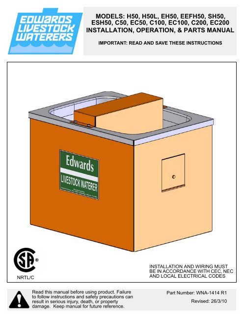
MODELS: H50, H50L, EH50, EEFH50, SH50,<br />
ESH50, C50, EC50, C100, EC100, C200, EC200<br />
INSTALLATION, OPERATION, & PARTS MANUAL<br />
IMPORTANT: READ AND SAVE THESE INSTRUCTIONS<br />
INSTALLATION AND WIRING MUST<br />
BE IN ACCORDANCE WITH CEC, NEC<br />
AND LOCAL ELECTRICAL CODES<br />
Part Number: WNA-1414 R1<br />
Revised: 26/3/10
This product has been designed and constructed according to general engineering<br />
standardsa . Other local regulations may apply and must be followed by the operator.<br />
We strongly recommend that all personnel associated with this equipment be trained<br />
in the correct operational and safety procedures required for this product. Periodic<br />
reviews of this manual with all employees should be standard practice. For your<br />
convenience, we include this sign-off sheet so you can record your periodic reviews.<br />
Date Employee Signature Employer Signature<br />
a. Standards include organizations such as the American Society of Agricultural and Biological Engineers,<br />
American National Standards Institute, Canadian Standards Association, International Organization for<br />
Standardization, and/or others.
EDWARDS GROUP - LIVESTOCK WATERER<br />
ALL MODELS<br />
TABLE OF CONTENTS<br />
1. Introduction .......................................................................................................................... 5<br />
2. Safety First............................................................................................................................ 7<br />
2.1. General Safety ......................................................................................................... 8<br />
2.2. Installation Safety ..................................................................................................... 9<br />
2.3. Operational & Maintenance Safety........................................................................... 9<br />
2.4. Safety Decal Locations............................................................................................ 9<br />
2.4.1. Decal Installation ........................................................................................ 9<br />
2.4.2. Decal Locations ........................................................................................ 10<br />
3. Installation .......................................................................................................................... 11<br />
3.1. Location.................................................................................................................. 11<br />
3.2. Installation .............................................................................................................. 11<br />
3.3. Electrical Installation............................................................................................... 13<br />
4. Operation ............................................................................................................................ 15<br />
4.1. Thermostat Operation ............................................................................................ 15<br />
4.2. Water Level Adjustment ......................................................................................... 15<br />
5. Maintenance ....................................................................................................................... 17<br />
5.1. General................................................................................................................... 17<br />
5.2. De-Icing <strong>Waterer</strong> .................................................................................................... 17<br />
5.3. Thermostat Replacement ....................................................................................... 17<br />
5.4. Floating Lid Kit Installation (Optional)..................................................................... 18<br />
6. Troubleshooting ................................................................................................................. 21<br />
6.1. Heat Problems........................................................................................................ 21<br />
6.2. Water Problems...................................................................................................... 22<br />
7. Appendix............................................................................................................................. 23<br />
7.1. <strong>Waterer</strong> Parts List................................................................................................... 23<br />
7.2. <strong>Waterer</strong> Specifications ........................................................................................... 25<br />
Warranty.................................................................................................................................. 27<br />
WNA-1414 R1 3
EDWARDS GROUP - LIVESTOCK WATERER<br />
ALL MODELS<br />
4 WNA-1414 R1
EDWARDS GROUP - LIVESTOCK WATERER 1. INTRODUCTION<br />
ALL MODELS<br />
1. Introduction<br />
Thank you for your purchase. This CSA approved unit is designed to provide<br />
water to livestock in virtually any farm environment, and is built with heavy gauge<br />
steel and a durable powder coat finish.<br />
Safe, efficient, and trouble-free operation of your waterer requires that you, and<br />
anyone else who will be involved with this unit, read and understand all safety<br />
instructions and procedures contained within this manual. A sign-off form is<br />
provided on the inside front cover for your convenience.<br />
Keep this manual handy for frequent reference and to review with new<br />
personnel. Call your local distributor or dealer if you need assistance, information,<br />
or additional copies of the manual.<br />
WNA-1414 R1 5
1. INTRODUCTION EDWARDS GROUP - LIVESTOCK WATERER<br />
ALL MODELS<br />
6 WNA-1414 R1
EDWARDS GROUP - LIVESTOCK WATERER 2. SAFETY FIRST<br />
ALL MODELS<br />
2. Safety First<br />
The Safety Alert symbol to the left identifies important safety messages on the<br />
product and in the manual. When you see this symbol, be alert to the possibility<br />
of personal injury or death. Follow the instructions in the safety messages.<br />
Why is SAFETY important to you?<br />
Three big reasons:<br />
• Accidents disable and kill.<br />
• Accidents cost.<br />
• Accidents can be avoided.<br />
SIGNAL WORDS<br />
Note the use of the signal words DANGER, WARNING, CAUTION, and NOTICE<br />
with the safety messages. The appropriate signal word for each message has<br />
been selected using the definitions below as a guideline.<br />
The Safety Alert symbol means ATTENTION, BE ALERT!, YOUR SAFETY IS<br />
INVOLVED.<br />
DANGER<br />
Indicates an imminently hazardous situation<br />
that, if not avoided, will result in serious injury<br />
or death.<br />
WARNING<br />
Indicates a hazardous situation that, if not<br />
avoided, could result in serious injury or<br />
death.<br />
CAUTION<br />
Indicates a hazardous situation that, if not<br />
avoided, may result in minor or moderate<br />
injury.<br />
NOTICE<br />
Indicates a potentially hazardous situation that, if not<br />
avoided, may result in property damage.<br />
WNA-1414 R1 7
2. SAFETY FIRST EDWARDS GROUP - LIVESTOCK WATERER<br />
2.1. GENERAL SAFETY ALL MODELS<br />
2.1. GENERAL SAFETY<br />
Important: The general safety section includes instructions that apply to all safety practices.<br />
Any instructions specific to a certain safety practice (e.g., assembly safety), can<br />
be found in the appropriate section. Always read the complete instructional<br />
sections and not just these safety summaries before doing anything with the<br />
equipment.<br />
YOU are responsible for the SAFE use and maintenance of your equipment.<br />
YOU must ensure that you and anyone else who is going to work around the<br />
equipment understands all procedures and related SAFETY information<br />
contained in this manual.<br />
Remember, YOU are the key to safety. Good safety practices not only protect<br />
you, but also the people around you. Make these practices a working part of your<br />
safety program.<br />
• It is the equipment owner and the operator's responsibility to read and understand<br />
ALL safety instructions, safety decals, and manuals and follow them<br />
before assembling, operating, or maintaining the equipment. All accidents<br />
can be avoided.<br />
• Equipment owners must give instructions and review the information initially<br />
and anually with all personnel before allowing them to operate this product.<br />
Untrained users/operators expose themselves and bystanders to possible<br />
serious injury or death.<br />
• Use this equipment for its intended purposes only.<br />
• Do not modify the equipment in any way. Unauthorized modification may<br />
impair the function and/or safety, and could affect the life of the equipment.<br />
Any modification to the equipment voids the warranty.<br />
• Do not allow children, spectators, or bystanders within the work area.<br />
• Have a first-aid kit available for use should the need arise, and know how to<br />
use it.<br />
• Provide a fire extinguisher for use in case of an accident. Store in a highly visible<br />
place.<br />
• Wear appropriate protective gear. This list includes, but<br />
is not limited to:<br />
• a hard hat<br />
•gloves<br />
• protective shoes with slip-resistant soles<br />
• protective goggles<br />
• hearing protection<br />
• For Powered Equipment: before servicing, adjusting, or repairing powered<br />
equipment, unplug, place all controls in neutral or off position, stop the engine<br />
or motor, remove ignition key or lock out power source, and wait for all moving<br />
parts to stop.<br />
8 WNA-1414 R1
EDWARDS GROUP - LIVESTOCK WATERER 2. SAFETY FIRST<br />
ALL MODELS 2.2. INSTALLATION SAFETY<br />
• Follow good shop practices:<br />
• keep service area clean and dry<br />
• be sure electrical outlets and tools are properly<br />
grounded<br />
• use adequate light for the job at hand<br />
• Think SAFETY! Work SAFELY!<br />
2.2. INSTALLATION SAFETY<br />
• Check all equipment for damage immediately upon arrival. Do not attempt to<br />
install a damaged item.<br />
• Have 2 people handle the heavy, bulky components.<br />
2.3. OPERATIONAL & MAINTENANCE SAFETY<br />
• Ensure that electrical cords are in good condition; replace if necessary.<br />
• Ensure the fan inlet is not plugged with any foreign material.<br />
• Keep inlet screen in place at all times.<br />
• Before resuming work, install and secure all guards. Keep guards in good<br />
working order.<br />
• Ensure parts are in good condition and installed properly.<br />
2.4. SAFETY DECAL LOCATIONS<br />
• Keep safety decals clean and legible at all times.<br />
• Replace safety decals that are missing or have become illegible. See decal<br />
location figures below.<br />
• Replaced parts must display the same decal(s) as the original part.<br />
• Safety decals are available from your distributor, dealer, or factory.<br />
2.4.1. DECAL INSTALLATION<br />
1. Decal area must be clean and dry, with a temperature above 10°C (50°F).<br />
2. Decide on the exact position before you remove the backing paper.<br />
3. Align the decal over the specified area and carefully press the small portion<br />
with the exposed sticky backing in place.<br />
4. Slowly peel back the remaining paper and carefully smooth the remaining<br />
portion of the decal in place.<br />
5. Small air pockets can be pierced with a pin and smoothed out using the sign<br />
backing paper.<br />
WNA-1414 R1 9
2. SAFETY FIRST EDWARDS GROUP - LIVESTOCK WATERER<br />
2.4. SAFETY DECAL LOCATIONS ALL MODELS<br />
2.4.2. DECAL LOCATIONS<br />
Replicas of the safety decals that are attached to the equipment are shown in the<br />
figure(s) that follow. Good safety requires that you familiarize yourself with the<br />
various safety decals and the areas or particular functions that the decals apply<br />
to as well as the safety precautions that must be taken to avoid serious, injury,<br />
death, or damage.<br />
Figure 2.1 Safety Decal Locations<br />
10 WNA-1414 R1
EDWARDS GROUP - LIVESTOCK WATERER 3. INSTALLATION<br />
ALL MODELS 3.1. LOCATION<br />
3. Installation<br />
Warning: Before continuing, please reread the safety information relevant to this section at<br />
the beginning of this manual. Failure to follow the safety instructions can result in serious<br />
injury, death, or property damage.<br />
3.1. LOCATION<br />
This waterer comes assembled and ready to install. You will be required to<br />
create a level mounting surface and to bring water and electrical supply lines to<br />
the waterer location.<br />
Before pouring the concrete pad, determine where to place the 1/2” x 3”<br />
mounting bolts. Insert bolts into the concrete with 1” of thread exposed. Figure<br />
3.1 shows the dimensional details for mounting bolts.<br />
The concrete pad should be a minimum of 8” thick with an extra 4” rise at the<br />
center for the waterer. It should also contain access for the riser pipe and power<br />
supply to pass through (Figure 3.2).<br />
Figure 3.1 Concrete Pad Mount Bolt Dimensions (top view)<br />
3.2. INSTALLATION<br />
1. Energy efficient models only: When installing waterer, slide up the 2” inner<br />
lining of high-quality insulation (4 pieces) to provide access to the mounting<br />
brackets. This allows the waterer to be bolted to the pad.<br />
WNA-1414 R1 11
3. INSTALLATION EDWARDS GROUP - LIVESTOCK WATERER<br />
3.2. INSTALLATION ALL MODELS<br />
2. To mount the waterer to the concrete pad, secure waterer to the 1/2” bolts<br />
that were set into the concrete.<br />
3. Push down the inner liner of insulation once the floor pieces are in place. The<br />
tighter the insulation is fitted, the more heat will be retained inside the box.<br />
4. Use a rubber strip or other sealant to seal the waterer to the pad. This<br />
minimizes heat loss in cold weather. Do not use insulation between the riser<br />
pipe and the culvert.<br />
5. Energy efficient models only: When the waterer is properly sealed and<br />
securely mounted, fit the extra pieces of insulation on the floor of the waterer,<br />
covering the concrete. The location of the culvert will determine how much<br />
fitting is necessary. As much of the floor as possible should be covered<br />
with insulation. Do not cover the culvert: this allows ground heat to<br />
enter the waterer.<br />
6. Use the flexible water hose (provided) to connect the riser pipe line to the<br />
waterer.<br />
7. A qualified electrician should complete the wiring of the waterer to the<br />
electrical supply line (see Section 3.3. for further details).<br />
Note: Installing a metal guard (not supplied) around the waterer at the pan level is<br />
recommended. This will help protect the unit from excessive wear from livestock<br />
rubbing against the waterer, thus prolonging its life.<br />
Figure 3.2 <strong>Waterer</strong> Installation<br />
12 WNA-1414 R1
EDWARDS GROUP - LIVESTOCK WATERER 3. INSTALLATION<br />
ALL MODELS 3.3. ELECTRICAL INSTALLATION<br />
3.3. ELECTRICAL INSTALLATION<br />
Note: All electrical connections and wiring must be completed in accordance with the<br />
current edition of the Canadian Electrical Code and/or the United States National<br />
Electrical Code.<br />
1. Run a watertight 3-wire conductor to the open knockout hole on the side of<br />
the receptacle/switch box.<br />
2. Use an approved strain relief connector to attach the conductor to the box.<br />
3. Secure the ground wire to the ground lug located inside the box.<br />
4. Connect the white supply wire to the white pigtail and the black supply wire to<br />
the black pigtail using a properly-sized twist connector.<br />
5. Replace switch faceplate on box and turn on power at source.<br />
Figure 3.3 Electrical Installation<br />
CAUTION<br />
All electrical work must be done by a qualified<br />
electrician in accordance with all applicable<br />
codes, standards, and the instructions<br />
contained within this manual.<br />
Be sure to ground waterer at junction box<br />
terminal.<br />
WNA-1414 R1 13
3. INSTALLATION EDWARDS GROUP - LIVESTOCK WATERER<br />
3.3. ELECTRICAL INSTALLATION ALL MODELS<br />
14 WNA-1414 R1
EDWARDS GROUP - LIVESTOCK WATERER 4. OPERATION<br />
ALL MODELS 4.1. THERMOSTAT OPERATION<br />
4. Operation<br />
Warning: Before continuing, please reread the safety information relevant to this section at<br />
the beginning of this manual. Failure to follow the safety instructions can result in serious<br />
injury, death, or property damage.<br />
Note: Do not modify any components and keep in good working order.<br />
4.1. THERMOSTAT OPERATION<br />
NOTICE<br />
For best results, ensure that the water level is set correctly.<br />
Failure to do so will cause freezing problems in cold<br />
weather.<br />
CAUTION<br />
This state-or-the-art, self-adjusting thermostat automatically keeps the water at<br />
the right temperature whether sub-zero or above normal winter temperatures.<br />
This eliminates energy waste and overheating the elements.<br />
The unit, totally sealed and without moving parts, gives the customer long-term,<br />
trouble-free service.<br />
4.2. WATER LEVEL ADJUSTMENT<br />
When closing lid, ensure flex cable and hose<br />
are properly positioned away from heating<br />
element.<br />
For optimum waterer operation, it is very important to set the proper water level.<br />
Set float arm so water level never rises above the stainless steel screws (see<br />
Figure 4.1).<br />
WNA-1414 R1 15
4. OPERATION EDWARDS GROUP - LIVESTOCK WATERER<br />
4.2. WATER LEVEL ADJUSTMENT ALL MODELS<br />
Figure 4.1 Water Level Adjustment<br />
16 WNA-1414 R1
EDWARDS GROUP - LIVESTOCK WATERER 5. MAINTENANCE<br />
ALL MODELS 5.1. GENERAL<br />
5. Maintenance<br />
Warning: Before continuing, please reread the safety information relevant to this section at<br />
the beginning of this manual. Failure to follow the safety instructions can result in serious<br />
injury, death, or property damage.<br />
5.1. GENERAL<br />
Important: Before performing any maintenance on this unit, lock out electrical power source.<br />
Monthly Maintenance:<br />
• Remove valve and check for sand. Clean as required or replace if necessary.<br />
Yearly Maintenance:<br />
Perform yearly maintenance before the heater is used at the beginning of each<br />
season.<br />
• Check that electrical connections are tight. Tighten any connections that are<br />
loose.<br />
• Check for rust on electrical connections. If rust is severe, replace wires.<br />
5.2. DE-ICING WATERER<br />
Before performing or attempting to thaw/de-ice the waterer, ensure that the<br />
power is disconnected and/or locked out. To thaw, use a blow-dyer, an infrared<br />
bulb, or pour hot water over the valve.<br />
5.3. THERMOSTAT REPLACEMENT<br />
Before replacing the thermostat, ensure that:<br />
• Heat-sensitive side of thermostat is completely flush with the stainless steel<br />
pan.<br />
• Black wire from thermostat is connected to incoming black wire from power<br />
source and the white wire from thermostat is connected to one of the white<br />
lead wires from the heater element.<br />
To put thermostat onto bracket:<br />
NOTICE<br />
Do not use a blowtorch or open flame to thaw or de-ice<br />
waterer. Damage to waterer will result.<br />
• Ensure that the heat-sensitive (smooth) side of thermostat is facing up and<br />
that the spring is holding this smooth side against the stainless steel pan.<br />
(Figure 5.1).<br />
WNA-1414 R1 17
5. MAINTENANCE EDWARDS GROUP - LIVESTOCK WATERER<br />
5.4. FLOATING LID KIT INSTALLATION (OPTIONAL) ALL MODELS<br />
• Do not over-tighten the clip screws: thermostat must not bind when clip is in<br />
place.<br />
• When electrical package is refit to the waterer, ensure that the heat sensitive<br />
surface of the thermostat is flush against the stainless steel pan.<br />
Figure 5.1 Thermostat Replacement<br />
5.4. FLOATING LID KIT INSTALLATION (OPTIONAL)<br />
The floating lid is an optional kit available with the livestock waterer and is<br />
designed to reduce heat loss. Instructions are included with kit, but are also<br />
included below.<br />
FOR C100 AND EC100 WATERERS ONLY:<br />
1. Remove existing float cover from livestock waterer.<br />
2. Turn off electrical power at the source.<br />
3. Turn off water supply.<br />
4. Disconnect hose and remove valve from waterer.<br />
5. Remove rubber washer and slip threadless plastic nut over plastic nipple<br />
(Figure 5.2).<br />
6. Slip rubber washer back onto nipple and reinstall valve in waterer pan.<br />
7. Reconnect hose, turn on water, and check for leaks.<br />
8. Adjust water level to water level mark on valve body.<br />
9. Turn power back on.<br />
FOR C50, EC100, EC50, AND C100 WATERERS:<br />
1. Fold template included with float lid installation kit along dotted line at 90°.<br />
18 WNA-1414 R1
EDWARDS GROUP - LIVESTOCK WATERER 5. MAINTENANCE<br />
ALL MODELS 5.4. FLOATING LID KIT INSTALLATION (OPTIONAL)<br />
2. Place template on float cover. Align the dark line with the edge of the float<br />
cover (refer to drawings on template).<br />
• For example: For holes on right side of float cover, align the right side line<br />
with the right edge of float cover (Figure 5.2).<br />
• For holes on left side of float cover, align the left side line with the left edge<br />
of float cover (Figure 5.2).<br />
3. Mark the appropriate holes (C50 or C100) on both sides of the float cover.<br />
4. Drill pilot holes using a 1/8” drill bit, then drill holes out to 1/4” diameter.<br />
5. Insert rods through the plastic floating lids ensuring that the smooth side of<br />
floating lid is upwards.<br />
6. Thread a 1/4” nut onto the threaded ends of each bent stainless steel rod.<br />
Run the nuts up to the ends of the thread.<br />
7. Insert the threaded rod ends through the holes in the float cover and put nut<br />
on the end of rod inside the float cover.<br />
8. Adjust rod positions by turning nuts in or out so that the clearance between<br />
the rod and float cover is approximately 5/8”.<br />
9. Repeat the procedure for other side of float cover: Reinstall float cover onto<br />
the waterer.<br />
10. If floating lids get hung up on the ends of the pan, it may be necessary to slot<br />
holes (Figure 5.2) and reposition the float cover.<br />
11. If lids continue to hang up after centering float cover, call factory for special<br />
instructions.<br />
WNA-1414 R1 19
5. MAINTENANCE EDWARDS GROUP - LIVESTOCK WATERER<br />
5.4. FLOATING LID KIT INSTALLATION (OPTIONAL) ALL MODELS<br />
Figure 5.2 Floating Lid Installation<br />
20 WNA-1414 R1
EDWARDS GROUP - LIVESTOCK WATERER 6. TROUBLESHOOTING<br />
ALL MODELS 6.1. HEAT PROBLEMS<br />
6. Troubleshooting<br />
6.1. HEAT PROBLEMS<br />
CAUTION<br />
Power must be turned off at breaker box<br />
before waterer is serviced.<br />
WATER FREEZES IN PAN<br />
Cause Solution<br />
Thermostat malfunction.<br />
• Ensure there is power to thermostat, or if necessary,<br />
replace thermostat.<br />
Thermostat may not positioned prop- • Ensure heat-sensitive side of thermostat is completely<br />
erly against pan surface.<br />
flush with the pan.<br />
Faulty heating element/pad.<br />
• Ensure element/pad is functioning. Check for power<br />
coming into the element/pad.<br />
• Ensure inspection door is properly insulated and posi-<br />
Too much heat loss from inside tioned and the pan is properly seated. Make sure the<br />
waterer box.<br />
WATER OVER-HEATING IN PAN<br />
base of the waterer box is sealed with weather-stripping<br />
or caulking.<br />
Cause Solution<br />
Thermostat is unable to sense water/<br />
pan temperature.<br />
• Ensure thermostat is flush with bottom of pan surface.<br />
Thermostat is touching the pan, but it is<br />
still overheating.<br />
• Replace thermostat.<br />
WNA-1414 R1 21
6. TROUBLESHOOTING EDWARDS GROUP - LIVESTOCK WATERER<br />
6.2. WATER PROBLEMS ALL MODELS<br />
6.2. WATER PROBLEMS<br />
WATER DOES NOT ENTER PAN, OR ENTERS SLOWLY<br />
Cause Solution<br />
• Install heat tape onto mainline to prevent mainline<br />
Mainline or valve frozen.<br />
•<br />
and valve from freezing.<br />
Properly insulate waterer box and caulk around bottom<br />
of the base to eliminate cold drafts.<br />
Valve bottom may have obstruction<br />
restricting water flow.<br />
• Remove valve from pan, inspect, and if necessary,<br />
clean out bottom half of valve of any obstruction that<br />
may be present.<br />
Top portion of valve may be over-tight- • Back pressure off of the 3 valve screws, empty bowl,<br />
ened to bottom portion (causes dia- and allow pan to refill. Water should seep out sides of<br />
phragm to rest directly on top of zytel<br />
seat; for proper flow of water, tolerance<br />
should be approximately 1/16” between<br />
diaphragm and zytel seat).<br />
valve (between the diaphragm and bottom of the<br />
valve). Retighten screws only until the seeping stops.<br />
This will ensure proper function of the valve.<br />
• Check water level. Float arm may need to be<br />
Plastic plunger is frozen to inside of adjusted to ensure proper water level. Excessive or<br />
valve top.<br />
improper water level will detour proper function of<br />
waterer.<br />
• Service pressure system to ensure adequate pressure.<br />
Pressure in water system is inadequate • Note: Excessive water pressure will cause seepage.<br />
to service waterer(s). Recommended Do not exceed 40–50 psi. If excessive water pressure<br />
water pressure: 40–50 psi.<br />
is present, use an inline flow restriction regulator<br />
device to ensure adequate pressure (at pressure system).<br />
• Ensure float is centered in float cover. Valve may<br />
Float may be frozen to side of float have to be turned slightly to achieve this.The float<br />
cover.<br />
must move freely up and down (in centre of float<br />
cover) to function properly.<br />
VALVE FAILS TO SHUT OFF AUTOMATICALLY AND WATER LEVEL CONTINUES TO RISE IN PAN<br />
Cause Solution<br />
• Turn water valve off. Remove 3 screws from valve top.<br />
Foreign matter (sand or grit) may be Clean bottom side of diaphragm and zytel seat. Exam-<br />
lodged between diaphragm bottom surine zytel seat for pitting. Replace zytel seat and/or diaface<br />
and zytel seat preventing proper phragm if damaged. Retighten screws.<br />
sealing of diaphragm.<br />
• If your water source continues to bring up particles,<br />
you may need to install a strainer filter in your pump<br />
house to remove any particles.<br />
Float adjustment may be too high. • See Figure 4.1 for water level adjustment.<br />
22 WNA-1414 R1
EDWARDS GROUP - LIVESTOCK WATERER 7. APPENDIX<br />
ALL MODELS 7.1. WATERER PARTS LIST<br />
7. Appendix<br />
7.1. WATERER PARTS LIST<br />
WNA-1414 R1 23
7. APPENDIX EDWARDS GROUP - LIVESTOCK WATERER<br />
7.1. WATERER PARTS LIST ALL MODELS<br />
24 WNA-1414 R1
EDWARDS GROUP - LIVESTOCK WATERER 7. APPENDIX<br />
ALL MODELS 7.2. WATERER SPECIFICATIONS<br />
7.2. WATERER SPECIFICATIONS<br />
ELECTRICAL DIMENSIONS<br />
ENERGY VOLTS HERTZ WATTS LENGTH WIDTH HEIGHT WEIGHT<br />
MODEL EFFICIENT (V) (Hz) (W) (cm) (in) (cm) (in) (cm) (in) (kg) (lb) CAPACITY<br />
C50 120 60 475 55 22 35 14 53 21 25 55 50-75 CATTLE<br />
H50 120 60 475 55 22 35 14 53 21 17 38 100-200 HOGS<br />
H50L 120 60 475 55 22 35 14 53 21 20 44 100-200 HOGS<br />
SH50 120 60 475 55 22 35 14 53 21 21 46 100-200 SHEEP<br />
C100 120 60 475 53 27 68 21 53 21 34 75 100-125 CATTLE<br />
C200 120 60 950 95 38 68 27 53 21 50 110 150-200 CATTLE<br />
EC50 120 60 300 55 22 35 14 53 21 26 57 50-75 CATTLE<br />
EH50 120 60 300 55 22 35 14 53 21 18 40 100-200 HOGS<br />
EH50L 120 60 300 55 22 35 14 53 21 21 46 100-200 HOGS<br />
ESH50 120 60 300 55 22 35 14 53 21 22 49 100-200 SHEEP<br />
EC100 120 60 300 53 27 68 21 53 21 35 77 100-125 CATTLE<br />
EC200 120 60 600 95 38 68 27 53 21 52 115 150-200 CATTLE<br />
WNA-1414 R1 25
7. APPENDIX EDWARDS GROUP - LIVESTOCK WATERER<br />
7.2. WATERER SPECIFICATIONS ALL MODELS<br />
26 WNA-1414 R1
WARRANTY<br />
Except as expressly provided in this agreement, <strong>Edwards</strong> Group (hereinafter called the Manufacturer)<br />
excludes all express or implied warranties, conditions, and obligations of the Manufacturer,<br />
whether statutory or otherwise, concerning the quality of the units or their fitness for any<br />
purpose.<br />
Under no circumstances will the Manufacturer be liable for any kind of special, consequential,<br />
indirect, or incidental damages resulting from the use of its products, nor shall the Manufacturer's<br />
liability ever exceed the selling price of the product.<br />
<strong>Edwards</strong> Group warrants their products as follows:<br />
1. Goods free from defect:<br />
a. The unit shall be free from defects in materials and workmanship and shall operate<br />
properly in accordance with industry standards when employed in normal usage, provided<br />
the unit has been properly installed for a period of: one (1) year from the original date of<br />
purchase.<br />
2. The warranty does not include:<br />
a. Routine replacement of parts due to normal wear and tear arising from use.<br />
b. Any defect attributable in whole or in part to misuse or improper installation.<br />
c. Any damage or defect attributable to repair of the unit outside the Manufacturer's facilities<br />
or those of an authorized dealer, or the installation of unapproved parts on the unit in the<br />
Manufacturer's judgment to affect it's performance or reliability, or which has been subject<br />
to misuse, negligence, or accident.<br />
d. Any damage attributable to accident or to lightning, power surge, brownout, leaking,<br />
damage, or connection to a power source having a greater rating than that specified in<br />
the unit specifications.<br />
3. Repair or Replacement<br />
Where any part of the unit fails during normal usage during the warranty period specified, the<br />
Manufacturer, or authorized dealer of the Manufacturer, shall repair or replace the defective part<br />
of the unit with a new or factory reconditioned part, such replacement or repair to be made without<br />
charge for parts or labor, F.O.B. the Manufacturer.<br />
4. Warranties shall not apply to any product made by the Manufacturer that has not been<br />
operated in accordance with the Manufacturer's printed instructions or shall have been<br />
operated beyond the rated capacity of the product or a use not intended.<br />
5. The Manufacturer reserves the right to make design or specification changes at any time,<br />
without contingent obligation to purchasers of products already sold.<br />
WARRANTY VOID IF NOT REGISTERED
<strong>Edwards</strong> Group is a Division of Ag Growth Industries LP<br />
Part of the Ag Growth International Inc. Group<br />
P.O. Box 1600<br />
Lethbridge, Alberta, Canada T1J 4K3<br />
Phone: (403) 320-5585<br />
Fax: (403) 320-5668<br />
Toll Free: (800) 565-2840 (Canada & USA)<br />
Website: www.edwardsgroup.ca<br />
© Ag Growth Industries Limited Partnership 2009