Conveyor chain
Conveyor chain
Conveyor chain

Create successful ePaper yourself
Turn your PDF publications into a flip-book with our unique Google optimized e-Paper software.
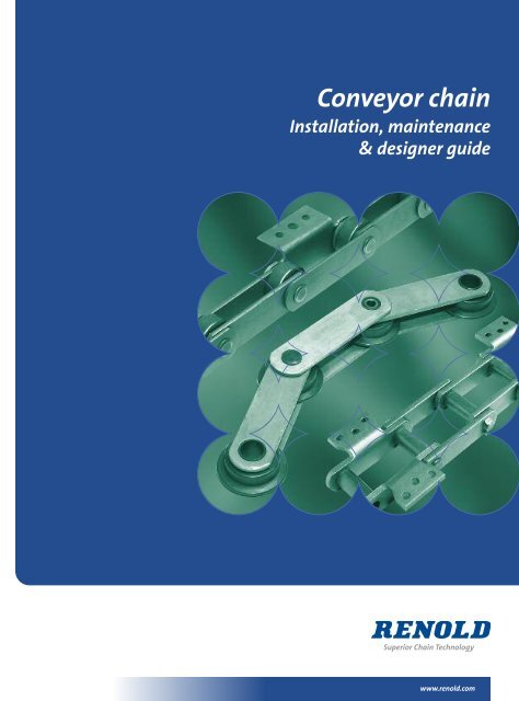
<strong>Conveyor</strong> <strong>chain</strong><br />
Installation, maintenance<br />
& designer guide<br />
www.renold.com
2 I Installation, maintenance & designer guide<br />
Renold Chain Product Range<br />
Roller Chain<br />
• British, ANSI, API, DIN, ISO<br />
and Works Standard Chains<br />
• Adapted Chains<br />
• Extended Pitch Chains<br />
• Hollow Pin Chains<br />
• Made to Order, Special Chains<br />
• Mini Pitch Chains<br />
Applications<br />
• Nickel Plated Chains<br />
• Oilfield Chains<br />
• Plastic Bush Chains<br />
• Power and Free Chains<br />
• Polymer Block Chains<br />
• Side Bow Chains<br />
• Stainless Steel Chains<br />
• Abattoirs • Air Conditioning • Aircraft - Civil & Military • Bakery Machines • Battery Manufacturing<br />
• Brewing • Canning • Carpet Machines • Chart Tables/Marine • Chocolate Manufacturing<br />
• Concrete Moulding Equipment • Copying Machines • Dairy Machinery • Drying Machinery<br />
• Earth Moving Equipment • Extrusion Machines • Filtration Plants • Food & Drink Manufacture<br />
• Glass Manufacture • Health Care Equipment • Hydraulic Components • Ice-Cream Manufacture<br />
• In-flight Refuelling • Ingot Casting & Scrap Metal Processing • Latex Machinery • Laundry Machinery<br />
• Lawnmower Manufacture • Mill Machinery • Mining • MOT Brake Testing Machinery • Nuclear Power<br />
• Off Road Vehicles • Oil Industry • Packaging Machines • Paper & Card Making • Paper Shredders<br />
• Plastic Machinery • Potato Grading Machinery • Power Generation • Printing Machines • Quarry Plant<br />
• Road Making & Plant Machinery • Robotic Systems • Roof Tile Manufacture • Ship's Engines<br />
• Silkscreen Machinery • Ski-Lifts • Soot Blowers • Steel Making • Straddle Carriers • Sugar Beet Machines •<br />
Sun-Blinds • Telecommunications • Textile Machinery • Timber and Woodworking Machines<br />
• Tin Printer Ovens • Tobacco/Cigarette Machinery • Tunnelling Machines • T.V. and Audio Equipment<br />
• Tyre Manufacture • Waste Handling • X-Ray Equipment<br />
<strong>Conveyor</strong> Chain<br />
• British, ISO and Works<br />
Standard Chains<br />
• Adapted Chains<br />
• Agricultural Chains<br />
• Bakery Chains<br />
• Deep Link Chains<br />
Applications<br />
• Escalator Chains<br />
• Made to Order, Specials<br />
• Stainless Steel Chains<br />
• Sugar Cane Chains<br />
• Zinc Plated Chains<br />
• Abattoirs • Agricultural Machines • Bakery Machines • Bottle Washing Plants<br />
• Brick & Tile Machinery OEM • Car Plants • Cement Plants • Chemical Plants • Chicken Process Equipment •<br />
Cigarette/Tobacco Machinery • Dust Filters • Egg Sorting <strong>Conveyor</strong>s • Electrical Switchgears • Escalators •<br />
Extrusion Machines • Feed Mill Machines • Feed Silo Equipment • Fibreglass Industry • Filtration Plants •<br />
Fish <strong>Conveyor</strong> • Food Sterilisation • Food Processing • Freezing Equipment • Freezing Tunnels • Glass<br />
Manufacturing • Grain <strong>Conveyor</strong> • Harvesting Machines • Ice Cream Machines • Induction Furnaces • Ingot<br />
Casting & Scrap Metal Processing Mfr • Latex Machinery • Leisure Rides • Luggage & Parcel Handling •<br />
Machine Tools • Mail Sorting • Metal Casting • Mushroom Compost Machinery • Nuclear • Ovens/Provers •<br />
Potato Grading Machinery • Potting Machinery • Quarries • Radio Astronomy • Roof Tile Manufacture<br />
• Rope Machinery • Saw Mill Equipment • Sewage Plants • Shaker <strong>Conveyor</strong>s • Ski-Lifts • Sluice Gates<br />
• Steel Making • Sugar Factories • Swarf <strong>Conveyor</strong>s • Textile Machinery • Timber & Woodworking Machines<br />
• Tool Changer • Tunnelling Machines • Tyre Manufacture • Washing & Sterilising Machines<br />
• Water Treatment • Wire Belts<br />
Lifting Chain<br />
• LH(BL), AL, LL and Works Standard Chains<br />
Applications<br />
• Bottle Washing Plants • Cement Plants • Chemical • Counterbalance Sets • Cranes<br />
• Dust/Swarf <strong>Conveyor</strong>s • Elevators • Food Processing • Food Sterilisation • Fork Lift Trucks<br />
• Pipe Line Valves/Taps • Printing Machines • Rock Drilling • Straddle Carriers • Sun-Blinds • Tail Lifts
Table of Contents<br />
Section 1 - <strong>Conveyor</strong> Chain Installation and Maintenance<br />
Installation and Maintenance guidelines and advice 4-20<br />
Installation, maintenance & designer guide I 3<br />
Section 2 - <strong>Conveyor</strong> Chain Designer Guide<br />
Specification guidelines and advice 21-61
4 I Installation, maintenance & designer guide<br />
Section 1<br />
<strong>Conveyor</strong> Chain<br />
Installation & Maintenance
Chain Installation and Maintenance<br />
Introduction<br />
Renold has, for many years, been a leader and<br />
innovator involved in the design and<br />
manufacture of standard conveyor <strong>chain</strong> and<br />
the development of engineered products for<br />
such applications as escalators, travelators,<br />
sterilizers, cement conveyors, leisure rides and<br />
numerous other specialised systems for the<br />
mechanical handling industry. We have a<br />
detailed understanding of the maintenance<br />
needs on such applications and can now offer<br />
the manufacturers and operators of conveyor<br />
systems the benefits of this knowledge.<br />
Chain is one of the most widely used moving<br />
mediums in mechanical handling systems,<br />
being robust and very adaptable, but it is also<br />
one of the most neglected components within<br />
such equipment when general or routine<br />
maintenance is carried out. In many cases this<br />
product is attended to when problems occur,<br />
normally when the <strong>chain</strong> is already damaged<br />
and the only real option is to fit a replacement<br />
to the system.<br />
This section has been designed with the<br />
manufacturer and operator in mind. It covers<br />
the functional aspects of using Renold conveyor<br />
<strong>chain</strong> and emphasizes the correct use of<br />
preventative maintenance procedures, which<br />
will ensure better machine performance, less<br />
down time, lower overall maintenance costs<br />
and extended <strong>chain</strong> life.<br />
Installation of New Chain<br />
When installing a complete set of new <strong>chain</strong>s<br />
the method of installation depends on the<br />
state of the conveyor, i.e. if the old <strong>chain</strong> is still<br />
in place, or the <strong>chain</strong> has been removed to<br />
allow refurbishing of the sprockets, tracks etc.<br />
Old Chain Still In Place<br />
On some installations where sprocket and track<br />
wear are minimal e.g. escalators, it is possible<br />
to replace the <strong>chain</strong> as the old <strong>chain</strong> is<br />
removed.<br />
Any fixtures, slats, steps, buckets etc., which<br />
join two or more <strong>chain</strong>s should be removed,<br />
except for enough to keep the <strong>chain</strong>s at the<br />
correct spacing. The <strong>chain</strong>s should then be<br />
broken at the tension end by removing an<br />
outer link or connecting link as necessary.<br />
Handling lengths of the new <strong>chain</strong>s can then<br />
be attached to the old <strong>chain</strong>s using old<br />
connecting links if possible. Care should be<br />
taken to ensure that the <strong>chain</strong>s are in the<br />
correct orientation. New fixtures should be<br />
connected to the new <strong>chain</strong> or old fixtures<br />
should be reconnected to maintain <strong>chain</strong> cross<br />
centres.<br />
The drive can then be used to inch the new<br />
<strong>chain</strong>s on and the old <strong>chain</strong>s off.<br />
When the new <strong>chain</strong>s have been fed onto the<br />
conveyor the next new handling lengths can be<br />
attached, this time using new connecting links.<br />
At the same time, the old <strong>chain</strong> can be<br />
disconnected from the lower strands. Repeat<br />
until all the <strong>chain</strong> has been replaced.<br />
No Chain in Place<br />
Where the conveyor has no <strong>chain</strong> in situ, (i.e.<br />
after refurbishing tracks etc., or a new<br />
conveyor), the method of installing <strong>chain</strong><br />
should be decided according to conveyor layout,<br />
access available and equipment available. The<br />
following notes are intended as a guide only.<br />
Fig. 1<br />
Installation, maintenance & designer guide I 5<br />
Horizontal & Inclined <strong>Conveyor</strong>s<br />
Where possible, <strong>chain</strong> should be fed on at the<br />
take-up end of the conveyor and pulled up to<br />
the drive end. When enough <strong>chain</strong> has been<br />
installed to fill up to the drive, the <strong>chain</strong> can<br />
then be inched over the drive sprocket and into<br />
the return tracks. Care should be taken to make<br />
sure that the <strong>chain</strong> is always restrained and<br />
cannot run back.<br />
NOTE: On horizontal conveyors, <strong>chain</strong> can be<br />
fed into the return tracks either over the drive<br />
or take-up wheels.<br />
On inclined conveyors the <strong>chain</strong> will need to be<br />
hauled up using a block and tackle, 'Tirfor' or<br />
winch (Fig. 1). Care should be taken to make<br />
sure that the <strong>chain</strong> is always restrained and<br />
cannot run back. On twin strand conveyors<br />
with slats/buckets etc., where access is<br />
available at the end of the conveyor, the <strong>chain</strong><br />
handling lengths can be fully assembled with<br />
slats/buckets etc. before being installed on the<br />
conveyor and then be drawn in as complete<br />
units.<br />
Section 1
Section 1<br />
6 I Installation, maintenance & designer guide<br />
Chain Installation and Maintenance<br />
Bucket Elevators<br />
On light duty elevators it may be possible, if<br />
access and space are available, to install the<br />
<strong>chain</strong> from the top of the elevator and join the<br />
<strong>chain</strong> at the drive sprocket.<br />
On heavy duty elevators (usually twin strand) it<br />
may be necessary to fully or partially assemble<br />
the <strong>chain</strong>s and buckets in handling lengths and<br />
lift them up through the bottom of the casing<br />
(Fig. 2). When enough <strong>chain</strong> has been<br />
assembled to reach the drive sprockets it can<br />
either be fed over the sprockets and driven<br />
down as more <strong>chain</strong> is installed and then<br />
joined at the bottom, or it can be secured at<br />
the top and the opposite side hauled up and<br />
joined at the top and the bottom.<br />
Assembly & Installation<br />
When assembling new <strong>chain</strong> or repairing<br />
existing <strong>chain</strong>, the following precautions are<br />
necessary.<br />
a) All power to the conveyor should be<br />
isolated before any work is started on the<br />
<strong>chain</strong>.<br />
b) Care should be taken to identify the <strong>chain</strong><br />
and to ensure that correct replacement<br />
links are at hand before breaking the <strong>chain</strong>.<br />
c) The <strong>chain</strong> tension should be slackened off<br />
completely so that joints are loose.<br />
d) The sprockets should be prevented from<br />
rotating whilst working on the <strong>chain</strong>,<br />
especially on inclined conveyors or<br />
elevators.<br />
e) The <strong>chain</strong> should be suitably restrained on<br />
both sides of the link to be broken, or<br />
connecting link to be removed.<br />
f) The correct working practices should be<br />
employed at all times.<br />
NOTE: Great care should be taken to secure<br />
<strong>chain</strong> properly in elevators to prevent it falling<br />
down inside the casing.<br />
Fig. 2<br />
The following points are also important and<br />
should be adhered to:i)<br />
The necks of connecting pins should not be<br />
ground or filed to ease insertion into the<br />
<strong>chain</strong> plates, nor should the plate holes be<br />
relieved. The press fit is an essential part of<br />
the <strong>chain</strong> construction and should not be<br />
destroyed.<br />
ii) Do not apply heat to the connecting plates<br />
to ease insertion of the connecting pins.<br />
This could seriously damage the material<br />
properties.<br />
Reconnecting Chain<br />
The method of <strong>chain</strong> connection depends upon<br />
the type of connecting link used. The main ones<br />
are either solid pin (i.e. No. 107, 58, 69, 86), or<br />
hollow pin (No. 107).<br />
Whichever type is used, the following steps are<br />
recommended:-<br />
Solid Pin Connectors<br />
a) Secure the <strong>chain</strong> on both sides of the<br />
assembly point.<br />
b) Unless the <strong>chain</strong> has to run unlubricated,<br />
coat the connecting pins with grease or oil<br />
and insert the pins into the two ends of the<br />
<strong>chain</strong>.<br />
c) Place the loose plate over the ends of the<br />
connecting pins and support the fixed plate<br />
side of the <strong>chain</strong> against the assembly<br />
force.<br />
d) Progressively force the loose plate onto the<br />
connecting pin necks equally and<br />
alternately, using a hollow punch and<br />
hammer or a hydraulic press or jack.<br />
(See Fig. 3).<br />
e) When the plate is fully seated, apply the<br />
connector e.g. nut, split pin or circlip, or<br />
rivet the pin end. (See following notes on<br />
riveting).<br />
Fig. 4<br />
f) Check that the assembled joint flexes<br />
freely. If it is tight, a light blow on the<br />
opposite end of the connecting pins should<br />
free the joint.<br />
Hollow Pin Connectors<br />
a) Secure the <strong>chain</strong> on both sides of the<br />
assembly point.<br />
b) Unless the <strong>chain</strong> has to run unlubricated,<br />
coat the hollow pins with grease or oil and<br />
insert the pins into the two ends of the<br />
<strong>chain</strong>.<br />
c) Place the loose plate over the ends of the<br />
hollow pins and support the <strong>chain</strong> on the<br />
fixed plate side against the assembly force.<br />
d) Progressively force the loose plate onto the<br />
hollow pin necks equally and alternately,<br />
using a hollow punch and hammer, a<br />
hydraulic press or jack, or a bolt and spacer<br />
type tool. (Fig. 4).<br />
e) When the plate is fully seated, rivet the pin<br />
ends (see following notes on riveting).<br />
f) Check that the assembled joint flexes<br />
freely. If it is tight, a light blow with a<br />
hammer on the opposite end of the<br />
hollow pins should free the joint.<br />
Fig. 3
Chain Installation and Maintenance<br />
Riveting Solid Pins<br />
To rivet a solid bearing pin, the <strong>chain</strong> should be<br />
supported on the opposite end of the bearing<br />
pin against the riveting force. On very small<br />
bearing pins, a couple of sharp taps with a<br />
hammer on the end of the pin will be enough<br />
to spread the rivet end. However, on larger<br />
bearing pins (i.e. 7500lb (33kN) breaking load<br />
and above) this will not be satisfactory. The<br />
outside edge of the pin needs to be peened<br />
over to form a satisfactory rivet. (Fig. 5).<br />
A hammer blow directly on the end of these<br />
larger pins will not be enough to accomplish<br />
this.<br />
Fig. 5<br />
This can be done with:a)<br />
A hammer, working around the pin head.<br />
(Care should be taken to hit the bearing pin<br />
edge and avoid damaging the link plate)<br />
(Fig. 6).<br />
b) Work around the pin head with a<br />
pneumatic hammer.<br />
(Again avoid damaging the link plate).<br />
c) A riveting punch and hammer,<br />
progressively turning the punch after each<br />
blow of the hammer to peen<br />
completely around the bearing pin head<br />
(Fig. 7). Use the factory riveted pins as a<br />
guide to rivet spread.<br />
Fig. 6<br />
Riveting Hollow Pins<br />
As for solid pins, the <strong>chain</strong> should be supported<br />
on the opposite end of the pin against the<br />
riveting force. The end of the bearing pin then<br />
needs to be slightly expanded to prevent the<br />
plate working off the pin. This can be done<br />
using a conical ended drift or a radiused punch<br />
and a hammer. Use the factory assembled pins<br />
as a guide to rivet spread. (Fig. 8).<br />
NOTE: When riveting <strong>chain</strong>, observe normal<br />
safety precautions. Wear safety glasses and<br />
protective clothing and make sure tools are in<br />
good condition and properly used.<br />
Fig. 7<br />
Fig. 8<br />
Installation, maintenance & designer guide I 7<br />
Adjustment<br />
Once the <strong>chain</strong> has been installed and all the<br />
fixtures are in place, adjustment of the <strong>chain</strong><br />
will be necessary before the <strong>chain</strong> is run. Care<br />
must be taken that the <strong>chain</strong> is not over<br />
adjusted, as this will add pre-tension into the<br />
<strong>chain</strong> which will in turn reduce <strong>chain</strong> life.<br />
The main requirement of <strong>chain</strong> adjustment is<br />
to remove slack from the <strong>chain</strong> (i.e. to take up<br />
the clearances between the pins and bushes in<br />
each link). Pre-tensioning of the <strong>chain</strong> is not<br />
required.<br />
On the majority of conveyors, a screw type<br />
take-up unit is used (see Fig. 9) due to its<br />
simplicity and lower cost. On this type of unit it<br />
is easy to keep on turning the adjustment<br />
screws and pre tension the <strong>chain</strong>, so great care<br />
is needed.<br />
Fig. 9<br />
Section 1
Section 1<br />
8 I Installation, maintenance & designer guide<br />
Chain Installation and Maintenance<br />
The following is a general guide to adjustment<br />
procedure:-<br />
a) Check that the tail shaft is in line, i.e.<br />
bearings are an equal distance back in the<br />
slides.<br />
b) Adjust the take up screws a few turns at a<br />
time, equally each side, until the <strong>chain</strong> no<br />
longer falls away from the bottom of the<br />
tail sprocket or drive sprocket. (See Fig.10).<br />
c) Lock the adjusting screws.<br />
d) Run the conveyor for at least one complete<br />
circuit to allow the <strong>chain</strong> to settle and<br />
recheck the <strong>chain</strong> adjustment.<br />
e) Re-adjust if necessary.<br />
Fig. 10<br />
Where an automatic take-up unit is used, i.e.<br />
pneumatic, hydraulic, spring etc., the amount<br />
of force exerted on the <strong>chain</strong> should be limited<br />
to prevent unnecessary pre tensioning.<br />
An assessment of the take-up force required on<br />
a simple two strand slat conveyor can be found<br />
using the following formula.<br />
Take-up force = (Chain pull at B + <strong>chain</strong> pull at<br />
C) + 10%.<br />
Using this value as a guide, the actual force can<br />
be established by experiment on site.<br />
After the <strong>chain</strong> has been adjusted and correctly<br />
lubricated, the conveyor should be left to run, if<br />
possible, for 8 to 24 hours without load to<br />
allow the <strong>chain</strong> components to bed in and<br />
bearing surfaces to polish smooth. After this<br />
period the take-up should be rechecked and<br />
adjusted if necessary.<br />
Throughout the life of the <strong>chain</strong> the take-up<br />
should be checked on a regular maintenance<br />
schedule and re-adjusted when necessary. For<br />
maximum allowable extension see page 61.<br />
Maintenance Planning<br />
To obtain the maximum performance from a<br />
set of <strong>chain</strong>s and sprockets with the least<br />
amount of down time and inconvenience when<br />
replacement is necessary, the maintenance of<br />
the equipment needs to be regular and on a<br />
planned basis.<br />
If there is no routine maintenance then the<br />
common occurrence happens, where <strong>chain</strong> on<br />
an important machine breaks or sprockets<br />
become badly worn and there are no<br />
replacements in stock and delivery time for<br />
replacements is a few weeks, the result is panic,<br />
a high cost in down time and inconvenience. By<br />
keeping a few spares in stock for important<br />
machines and with a little forethought, this can<br />
be prevented.<br />
Performance Monitoring<br />
The performance monitoring service offered by<br />
Renold is designed to give customers peace of<br />
mind in operating any <strong>chain</strong> system by<br />
knowing the current condition of the <strong>chain</strong> and<br />
sprockets.<br />
Performance monitoring enables companies to<br />
monitor the wear rates of <strong>chain</strong> and plan<br />
replacements well ahead, thus avoiding<br />
expensive breakdown and downtime and<br />
ensuring that replacement <strong>chain</strong>s can be<br />
ordered in time to avoid delivery problems.<br />
Performance monitoring consists of several<br />
stages:-<br />
1. On site examination:- Renold engineers will<br />
visit the site and carry out in depth<br />
examination of plant, both moving and<br />
stationary. This can determine if any<br />
serious problems of alignment, tracking,<br />
sprocket wear or eccentricity are evident<br />
and if methods of operation, maintenance<br />
or installation are likely to cause future<br />
problems.<br />
2. Sample measurement:- Samples removed<br />
on a periodic basis are stripped down to<br />
component level and measured for wear,<br />
abrasion or deformation.<br />
3. Sample Reporting:- A full report of the<br />
measurement and examination is prepared<br />
by our laboratory and a copy submitted to<br />
the customer together with the Renold<br />
Engineer’s assessment of the <strong>chain</strong><br />
condition and suitability for further service.<br />
The comparison is also made between<br />
current sizes and manufactured sizes.<br />
4. Wear Monitoring:- Analysis of inspection<br />
reports over a period can enable customers,<br />
in conjunction with Renold Engineers, to<br />
predict the effective life of a <strong>chain</strong>,<br />
providing conditions of operation do not<br />
change. If changes are made, discussions<br />
with Renold can determine the likely<br />
effects beforehand.
Chain Installation and Maintenance<br />
Maintenance Schedule<br />
A typical maintenance schedule is laid out<br />
below. This should be adapted to suit each<br />
specific application, based on the local<br />
conditions and duty cycle.<br />
Typical Maintenance Schedule<br />
EVERY WEEK<br />
• Check lubrication and lubricate if necessary.<br />
FIRST MONTH'S RUNNING<br />
• Check <strong>chain</strong> take-up and adjust if necessary.<br />
• Check for unusual wear and identify cause<br />
and rectify.<br />
AFTER 3 MONTHS<br />
• Check <strong>chain</strong> adjustment and rectify if<br />
necessary.<br />
• Change oil, oil filter and clear the sump, if<br />
lubrication system fitted<br />
Fig. 11<br />
EVERY 3 MONTHS<br />
• Check <strong>chain</strong> take-up and adjust if necessary.<br />
• Check unusual wear and identify cause and<br />
rectify.<br />
ANNUALLY<br />
• Carry out the above checks.<br />
• Check for wear on side plates.<br />
• Check for <strong>chain</strong> elongation.<br />
• Check cleanliness of components.<br />
- Remove any accumulation of dirt or<br />
foreign materials.<br />
• Check for shaft and sprocket alignment.<br />
• Check for wear on sprockets.<br />
• Check the condition of the lubricant.<br />
• Check the lubrication system.<br />
Installation, maintenance & designer guide I 9<br />
Lubrication<br />
Effective lubrication of the <strong>chain</strong> bearing<br />
surfaces is essential to obtain optimum<br />
performance in addition to minimising power<br />
absorption, rate of wear, probability of<br />
corrosion and noise.<br />
For normal conditions a good quality mineral<br />
oil with medium viscosity, for example SAE<br />
20W50, is recommended where operating<br />
temperatures are normal.<br />
The standard treatment given to every Renold<br />
<strong>chain</strong> before leaving the factory, unless<br />
otherwise requested, is to immerse the <strong>chain</strong> in<br />
a grease which, when solidified, will act as a<br />
protection and preliminary lubricant for the<br />
<strong>chain</strong>. Re-lubrication should be carried out<br />
immediately after installation of the <strong>chain</strong> with<br />
a suitable lubricant and at regular intervals<br />
thereafter. The following selection procedure<br />
for conveyor <strong>chain</strong> lubrication is designed to<br />
give users an idea of the types of lubrication to<br />
be used in conditions where normal lubricants<br />
would be inadequate. (See Fig 11).<br />
Section 1
Section 1<br />
10 I Installation, maintenance & designer guide<br />
Chain Installation and Maintenance<br />
Industry<br />
Some industries will have special needs from a<br />
selected lubricant. These needs will usually be<br />
determined by the demands of the product<br />
handled and the product susceptibility to<br />
contamination and spoiling by direct or indirect<br />
contact with lubricant. Some industries with<br />
these special needs are listed and users should<br />
contact lubricant specialists for<br />
recommendations.<br />
Marine Industry Tobacco<br />
Ceramics Sugar<br />
Textiles Hospital Equipment<br />
Food Industry Nuclear Environment<br />
Water<br />
Temperature Considerations<br />
Low temperature conditions -60°C to 0°C,<br />
require application of low temperature, water<br />
repellent grease to lubricate and prevent<br />
condensation water freezing and locking the<br />
<strong>chain</strong>. Low temperature lubricants are designed<br />
to be both lubricants and water repellents.<br />
They comprise synthetic oils in an organic or<br />
inorganic carrier. Lubrication is by means of<br />
synthetic polymers which, under load, form<br />
<strong>chain</strong>s to provide a passive film on friction<br />
surfaces. They will not mix with, and actively<br />
repel, water. Temperature range -60°C to<br />
+120°C.<br />
High temperature 100°C to 450°C.<br />
Up to 160°C a wet film lubricant is generally<br />
used. Above 160°C a suitable dry-film, noncarbonising<br />
lubricant is generally employed.<br />
Wet-film, high temperature lubricants are<br />
usually solid lubricants (greases), which are<br />
dispersed in a chlorinated hydrocarbon solvent.<br />
This allows penetration of lubricant into critical<br />
areas, after which solvent evaporation occurs.<br />
(Temperature range -25°C to + 160°C).<br />
Dry-film, high temperature lubricants usually<br />
consist of colloidal molybdenum disulphide or<br />
graphite in a non-carbonising synthetic carrier.<br />
This carrier penetrates into the critical areas of<br />
the <strong>chain</strong> and then evaporates, leaving a dry<br />
MoS2 or graphite film. (Temperature range 0°<br />
to + 450°C).<br />
Dusty Conditions<br />
Chain should be prelubricated before operation<br />
with a suitable dry film lubricant to prevent<br />
dust adhering to the lubricant. Periodically the<br />
<strong>chain</strong> should be cleaned and re-lubricated with<br />
the same lubricant.<br />
Chains fitted with grease gun lubricated pins<br />
and bushes are most effective in these<br />
environments.<br />
Hot and Dusty Conditions<br />
The same considerations should be used as for<br />
dusty conditions, but the dry film lubricant<br />
should be chosen to be effective at the<br />
operating temperature.<br />
Water Environments-Clean<br />
In water plants, <strong>chain</strong>s are usually operating<br />
above water level and therefore require<br />
lubricants that are effective, but sufficiently<br />
adhesive to not fall into potential drinking<br />
water. Lubricants are available as special heavy<br />
greases and these are most effective when<br />
applied to the <strong>chain</strong> components during <strong>chain</strong><br />
assembly. Water industry grease comprises a<br />
blend of mineral oil, graphite, hydrophobic and<br />
anti-corrosive elements. Each in its turn will<br />
lubricate, repel water and prevent corrosion.<br />
The grease will not dilute in water, is extremely<br />
adhesive and actively repels water. The same<br />
heavy duty greases are available for <strong>chain</strong>s<br />
operating in water where contamination is not<br />
a problem. Regular regreasing is necessary in<br />
this case. Water authority approval may be<br />
required for lubricants used near drinking<br />
water.<br />
Water Environments - Dirty<br />
Chains operating in sewage treatment works<br />
are frequently completely immersed and, other<br />
than a prelubrication, it is impossible to<br />
lubricate regularly. In these cases, <strong>chain</strong>s are<br />
selected to operate sacrificially, or special<br />
materials are selected to operate in a<br />
continuously wet environment. Where <strong>chain</strong>s<br />
are accessible for lubrication, grease gun<br />
lubricated <strong>chain</strong>s should be used with water<br />
repellent grease to periodically flush out the<br />
old grease and contaminants.<br />
Solvent Environments<br />
Where <strong>chain</strong>s are operating in a solvent<br />
atmosphere, then lubricants must be chosen<br />
with great care. Regular re-lubrication is usually<br />
not possible due to removal of lubricant by the<br />
solvent, causing solvent (and therefore product)<br />
contamination. Lubrication suppliers should be<br />
consulted and a product obtained that will not<br />
be dissolved by the solvent.<br />
Other Wet Environments<br />
These special environments must be<br />
individually considered. Consult specialist<br />
lubricant supplier or contact Renold.
Chain Installation and Maintenance<br />
9. Toxic or Corrosive<br />
Environments<br />
Specialist lubricants must be obtained for these<br />
conditions and selection will depend upon the<br />
material being handled. Consult specialist<br />
lubricant supplier or contact Renold.<br />
10. Application Methods<br />
Manual. By oil can, brush or aerosol, applied<br />
directly on the <strong>chain</strong>. Automatic. By drip feed,<br />
preferably one shot lubrication which deposits<br />
the correct amount of lubricant at the correct<br />
time in the correct place on the <strong>chain</strong>. It is<br />
imperative that lubrication is accurately<br />
applied. Too much lubricant is as harmful as<br />
too little. Incorrect application of lubricant will<br />
result in irregular motion of the <strong>chain</strong>,<br />
particularly at low speed or light loads due to<br />
“stick slip”.<br />
11. Pre Treatments<br />
The following pre treatments can be applied<br />
during the manufacture of <strong>chain</strong> components<br />
and the advantages are listed. Phosphating.<br />
The application of a manganese phosphate<br />
coating to pin and bush surfaces. The surface<br />
gives a small degree of pre-lubrication, but its<br />
main advantage is to provide a key for<br />
subsequent lubrication and makes this much<br />
more effective and resilient. Molybdenum<br />
Disulphide. A coating applied to pins and<br />
bushes during manufacture by dipping,<br />
followed by oven curing. Lowers friction<br />
between components and acts as preliminary<br />
lubricant. The film is only a few microns thick<br />
and is eroded in abrasive conditions. PTFE.<br />
Coating applied as above, with very similar<br />
characteristics.<br />
12. Unlubricated<br />
Some environments preclude the use of any<br />
type of lubrication or precoating, due either to<br />
product contamination or the possibility of<br />
creating volatile compounds or grinding pastes.<br />
In these cases, <strong>chain</strong> life will be improved by<br />
periodic cleaning or washing<br />
to remove materials built up over the <strong>chain</strong>.<br />
Compressed air can sometimes be<br />
recommended should material be loose and<br />
light in mass.<br />
Lubricant Application Methods<br />
It is important that lubricant is applied to the<br />
correct parts of a <strong>chain</strong>. To merely brush<br />
lubricant over the <strong>chain</strong> plates will prevent<br />
external corrosion but will not necessarily<br />
benefit the bearing surfaces. Lubricant should<br />
be applied between the inner and outer plates<br />
above each pitch point, and between the inner<br />
plates and roller if a roller is fitted. This should<br />
ensure that the lubricant flows into the bearing<br />
surfaces (Fig. 12).<br />
Fig. 12<br />
Installation, maintenance & designer guide I 11<br />
Care should be taken that the correct amount<br />
of lubricant is applied. Too much lubricant can<br />
lead to roller treads and tracks being<br />
contaminated, with subsequent loss of roller<br />
traction. At slow speeds and with light loads<br />
this can lead to uneven motion i.e. “stick slip”. A<br />
further problem can be flats appearing on the<br />
roller treads which eventually prevent the<br />
rollers turning and thus increase the power<br />
required to drive the conveyor.<br />
Lubricant is usually applied to the <strong>chain</strong> by one<br />
of the following methods:-<br />
Manually<br />
The three main methods of applying lubricant<br />
manually are by oil can, brush or aerosol. The<br />
frequency of lubrication will vary depending on<br />
environmental conditions. In some cases once<br />
per day may be necessary, in others once per<br />
week or two weeks.<br />
Lubricant should ideally be applied to the <strong>chain</strong><br />
as it leaves the drive sprocket, i.e. at point of<br />
minimum tension. This will allow the lubricant<br />
to penetrate into the bearing surfaces.<br />
When a new set of <strong>chain</strong>s has been installed, or<br />
if the conveyor has been standing for a long<br />
time, it should be allowed to run unloaded for a<br />
few hours after the lubricant has been applied<br />
to allow it to work into the <strong>chain</strong> effectively.<br />
Section 1
Section 1<br />
12 I Installation, maintenance & designer guide<br />
Chain Installation and Maintenance<br />
Auto-Lube<br />
The main types of auto-lube systems are drip<br />
feed, single shot and oil mist spray. All systems<br />
consist of a fixed set of pipes, an oil reservoir<br />
and the necessary control valves and pumps.<br />
The purpose of the system is to automatically<br />
deposit an amount of oil in the <strong>chain</strong> as it<br />
passes the oil discharge point. Drip feed<br />
systems are usually gravity fed, but the single<br />
shot and oil mist spray are usually pneumatic.<br />
The system should be switched on once per<br />
day, once per week, or however necessary for<br />
one or two complete circuits of the <strong>chain</strong> to<br />
ensure the bearing surfaces are satisfactorily<br />
lubricated. Unless the conveyor is part of a<br />
process where the lubricant is continually being<br />
washed off the <strong>chain</strong>, the lubricator should not<br />
be run continually.<br />
Grease Gun<br />
In certain applications, <strong>chain</strong> is designed for<br />
grease gun lubrication. This <strong>chain</strong> has bearing<br />
pins and bushes cross drilled to allow the<br />
grease to penetrate into the bearing surfaces<br />
(see fig. 13) from within the <strong>chain</strong>. Grease<br />
nipples are fitted to the ends of the bearing<br />
pins to allow grease to be injected into the<br />
<strong>chain</strong>. This has the advantage that any dirt or<br />
contaminants that get into the <strong>chain</strong> are forced<br />
out as the grease is injected.<br />
This types of <strong>chain</strong> is pregreased at the factory<br />
and can be re-lubricated either by manual<br />
grease gun or by an automatic grease<br />
lubrication system. As with other methods, the<br />
regularity of re-lubrication depends on the<br />
environment and application of the <strong>chain</strong>.<br />
Chain & Sprocket Storage<br />
Chain<br />
Before <strong>chain</strong> leaves the Renold factory it is prelubricated<br />
with a grease which acts as a<br />
corrosion protective and anti-fretting lubricant.<br />
For shipment they are either stacked on pallets<br />
and then shrink wrapped or packed into<br />
wooden boxes. If the <strong>chain</strong> is to be stored on<br />
site for weeks or months before use, it should<br />
be left in the packing for protection. It should<br />
not be stored in an open area where dust, dirt<br />
and water are present. If <strong>chain</strong> equipment is to<br />
be left idle for long periods, clean the <strong>chain</strong> and<br />
sprockets (i.e. brushing or steam cleaning) and<br />
then cover them with oil. If <strong>chain</strong> is removed<br />
from a machine for storage, try to store it in a<br />
container filled with old engine oil or similar.<br />
Where it is not possible to store <strong>chain</strong>s in a<br />
lubricated environment, they should be<br />
lubricated on installation and run unloaded for<br />
at least 24 hours.<br />
Sprockets<br />
Sprockets usually leave the works shrink<br />
wrapped on pallets or in wooden boxes. All<br />
surfaces are painted before despatch except<br />
where they have been machined (i.e. cut teeth<br />
or bored and keywayed). If the sprockets are<br />
not to be used within a few days of receipt,<br />
then all machined surfaces should be painted<br />
with a heavy oil or grease to prevent corrosion.<br />
As stated for the <strong>chain</strong>, do not store in an open<br />
area where dust, dirt and water are present.<br />
Fig. 13<br />
General Inspection<br />
Chain needs to be checked on a regular basis<br />
throughout its life, to ensure any faults in the<br />
machine are detected at an early stage so that<br />
rectification work can be carried out to prevent<br />
further damage.
Chain Installation and Maintenance<br />
Inspection of <strong>chain</strong> should not be left until a<br />
major breakdown has occurred. This may result<br />
in expensive replacement of major parts and<br />
long down time if the required new parts are<br />
not readily available.<br />
On drive <strong>chain</strong> the major factor determining<br />
<strong>chain</strong> life is extension due to wear between the<br />
bearing pin and bush. However, on a conveyor<br />
<strong>chain</strong> the life may be determined by wear on<br />
other components, depending on the<br />
environment in which the <strong>chain</strong> is used. Where<br />
accessible, the <strong>chain</strong> should be checked for<br />
wear as follows:-<br />
Extension of Chain Pitch<br />
A direct measure of <strong>chain</strong> wear is the extension<br />
in <strong>chain</strong> pitch due to the wear between bearing<br />
pin and bush. This is caused by the <strong>chain</strong><br />
articulating under tension around the drive<br />
sprockets and can usually be obtained by direct<br />
measurement as follows:-<br />
Measure a length of <strong>chain</strong> over as many pitches<br />
as possible. The <strong>chain</strong> must be on a straight<br />
section of track and under tension. This<br />
measured length "M" can then be applied to<br />
the following formula to obtain the percentage<br />
extension.<br />
Fig. 14<br />
Percentage extension = [M - (X x P)] x 100<br />
X x P<br />
Where M = Measuring length (mm)<br />
X = Number of pitches measured<br />
P = Chain pitch (mm)<br />
The maximum allowable percentage extension<br />
is shown in the following tables for the relevant<br />
series of <strong>chain</strong>s. When the <strong>chain</strong> extension has<br />
reached this figure, the <strong>chain</strong> is due for<br />
replacement. If regular measurements are<br />
taken and results recorded, it is possible to<br />
predict how long the <strong>chain</strong> will last and when<br />
replacement will be required. The necessary<br />
steps can then be taken to ensure the <strong>chain</strong> is<br />
available and avoid any sudden panic.<br />
Chain Allowable % Chain Allowable %<br />
Series Extension Series Extension<br />
BS Chains<br />
3000lb 40.6 24000/30000lb 102<br />
(13KN) P (107KN/134KN) P<br />
4500lb 40.6 36000/45000lb 102<br />
(20KN) P (160KN/200KN) P<br />
6000/7500lb 50.8 60000lb 127<br />
(27KN/33KN) P (267KN) P<br />
12000/15000lb 76.2 90000lb 127<br />
(54KN/67KN) P (400KN) P<br />
ISO Chains<br />
M40 76 MC224 128<br />
P P<br />
M56 88 M315 168<br />
P P<br />
MC56 71 M450 180<br />
P P<br />
M80 102 M630 203<br />
P P<br />
M112 97 M900 230<br />
P P<br />
MC112 97<br />
P<br />
Roller Wear<br />
On long centred conveyors for example where<br />
the load is carried by the <strong>chain</strong> rollers running<br />
along a track, the rollers are continually turning<br />
under load against the bushes. The pin and<br />
bush only turn against each other four times<br />
per circuit of the conveyor (only one of these<br />
is under full load). Under these circumstances<br />
roller wear can be the limiting factor in<br />
<strong>chain</strong> life.<br />
Installation, maintenance & designer guide I 13<br />
An idea of the amount of roller wear can be<br />
obtained by measuring the clearance between<br />
the bottom of the link plates and the track<br />
surface and comparing the result with that<br />
obtained on a new piece of <strong>chain</strong>. See Fig. 15.<br />
If the rollers have worn to the point where the<br />
link plates are near to or are rubbing on the<br />
tracks, then replacement is necessary. If<br />
standard <strong>chain</strong> is fitted it is not possible to<br />
replace just the rollers, therefore the complete<br />
<strong>chain</strong> should be replaced. If outboard rollers are<br />
fitted then it may be possible to replace the<br />
rollers only.<br />
Where bends occur in the tracks, extra care<br />
should be taken with roller wear assessment as<br />
less wear is allowable before the link plate<br />
edges contact the tracks. See Fig. 16.<br />
Fig. 15<br />
Fig. 16<br />
Link Plate Wear<br />
Wear on link plates can appear in various ways,<br />
due to a number of different causes and in<br />
some cases can mean premature <strong>chain</strong><br />
replacement.<br />
On scraper conveyors or conveyors where the<br />
<strong>chain</strong> runs on its link plate edges, wearing away<br />
of the plate edges can occur, which will reduce<br />
the plate depth and thus the tensile strength of<br />
the <strong>chain</strong>. (See Fig. 17).<br />
This wear should not exceed more than half<br />
the original plate depth above the bush,<br />
otherwise a <strong>chain</strong> breakage could occur. When<br />
wear has occurred to this extent the <strong>chain</strong><br />
should be replaced. In some cases, to extend<br />
<strong>chain</strong> life it may be possible to turn the <strong>chain</strong><br />
over so that the unworn edge of the <strong>chain</strong><br />
becomes the wearing surface. This will depend<br />
on the type of <strong>chain</strong>, fixtures on the <strong>chain</strong> and<br />
the make-up of the <strong>chain</strong>. (See Fig. 18).<br />
Fig. 17<br />
Section 1
Section 1<br />
14 I Installation, maintenance & designer guide<br />
Chain Installation and Maintenance<br />
Fig. 18<br />
The rubbing friction between the roller side<br />
face and the inside of the inner links can<br />
produce wear on the inner link plate. If this<br />
occurs before signs of wear on other<br />
components, it is a sign of misalignment in the<br />
conveyor. In this case, roller treads should also<br />
be checked for signs of tapered wear.<br />
(See Fig. 19).<br />
Similar wear may occur between the inner and<br />
outer link plates (see Fig. 20) (although this is<br />
not common on the BS series of <strong>chain</strong>s, due to<br />
the bush projection from the inner link plates<br />
which creates a gap between the inner and<br />
outer plates). Again, this is usually a sign of<br />
mis-alignment. In both cases, if the plate<br />
thickness has been reduced by more than 1/3<br />
of its original thickness the <strong>chain</strong> strength is<br />
substantially reduced and the <strong>chain</strong> should be<br />
replaced after first rectifying the misalignments.<br />
Fig. 19<br />
Fig. 20<br />
i.e. Check the following:-<br />
A) Alignment of head and tail wheels.<br />
B) Shaft alignments.<br />
C) Level across tracks.<br />
If possible, the <strong>chain</strong> should be checked for<br />
marking or damage to the inner plate edges<br />
and marking or wear on the inside faces of the<br />
inner links. This is due to the sprocket teeth<br />
rubbing on the plates as the <strong>chain</strong> engages<br />
with the sprocket. Light marking is usual, due<br />
to normal movement of <strong>chain</strong>. However, if<br />
wear is heavy and plate thickness is reducing,<br />
sprocket spacing or alignment should be<br />
checked and rectified and severely damaged<br />
links replaced.<br />
Bush Wear<br />
Unless the conveyor uses a bush <strong>chain</strong> (i.e.<br />
<strong>chain</strong> without rollers), it is not usually possible<br />
to detect bush wear or damage without<br />
dismantling a piece of <strong>chain</strong> into its component<br />
parts.<br />
If a bush <strong>chain</strong> is used, checks should be made<br />
for wear on the outside of the bush. This wear<br />
could be due to either the bush sliding along<br />
the tracks or the bush gearing with the <strong>chain</strong><br />
sprockets. If the bush is worn through so that<br />
the bearing pin is exposed, then the <strong>chain</strong><br />
should be replaced. In certain circumstances it<br />
may be possible to turn the <strong>chain</strong> over and<br />
wear the opposite face of the bush to extend<br />
the <strong>chain</strong> life. (In this case, advice from Renold<br />
should be sought).<br />
Fig. 21<br />
Should any cracked or broken bushes be found,<br />
then the cause should be identified and<br />
rectified, then depending on the extent of the<br />
damage, either links or the complete <strong>chain</strong><br />
should be replaced.<br />
Bearing Pin Wear<br />
Normal bearing pin wear shows up as pitch<br />
extension and can be detected as stated on<br />
page 61.<br />
Wear of the bearing pin heads can be caused by<br />
either insufficient clearance between the <strong>chain</strong><br />
and side guides, tracks not level across the<br />
conveyor causing the <strong>chain</strong> to run over to the<br />
lower level, <strong>chain</strong> twisted due to abuse, or bad<br />
<strong>chain</strong> guidance.<br />
The cause should be identified and rectified. If<br />
the bearing pin heads have worn down level<br />
with the <strong>chain</strong> plates, then the rivet will be<br />
ineffective and either the bad links or the<br />
complete <strong>chain</strong> should be replaced.<br />
General<br />
General visual inspection of the <strong>chain</strong> should<br />
be carried out with the forgoing to detect<br />
broken components, broken or damaged<br />
attachments, severe corrosion, seized joints or<br />
any unusual occurrences. The causes of these<br />
should be identified and rectified and damaged<br />
<strong>chain</strong> replaced.<br />
Sprocket Tooth Wear<br />
Normal wear takes place due to the<br />
engagement of the <strong>chain</strong> with the sprocket<br />
teeth and shows up as a polished or worn strip<br />
on the face of the tooth gap near the root (i.e.<br />
about the PCD). Wear generally occurs faster on<br />
sprockets driving bush <strong>chain</strong>s rather than roller<br />
<strong>chain</strong>s. This is due to the sliding engagement of<br />
the bush on the tooth as opposed to the rolling<br />
engagement of the roller.<br />
Usually as the sprocket wears, this shows up as<br />
a concavity or hooking of the tooth flank. If this<br />
is allowed to continue it will start to impede<br />
<strong>chain</strong> engagement/disengagement and on<br />
short pitch <strong>chain</strong>s weaken the tooth.<br />
(See Fig. 22).<br />
Fig. 22
Chain Installation and Maintenance<br />
Fig. 23<br />
If the <strong>chain</strong> has not been kept in correct<br />
adjustment and runs slack it may tend to<br />
resonate and jump the teeth, causing the wear<br />
pattern shown in Fig 23. This can be rectified by<br />
correcting the <strong>chain</strong> adjustment and if<br />
necessary replacing the sprocket.<br />
Given adequate lubrication and <strong>chain</strong><br />
maintenance, the sprockets should last the life<br />
of the <strong>chain</strong>.<br />
Measurement of Tooth Wear<br />
Quite often it is only possible to make visual<br />
inspection of the tooth gap. However, if the<br />
sprockets are accessible during routine<br />
maintenance, then one of the following<br />
methods should be used to measure for wear.<br />
i) Clean the tooth gap of oil, grease or any<br />
other matter and apply to the tooth gap an<br />
"as new" template. (Fig. 24).<br />
Fig. 24<br />
ii) Clean the tooth gap as above and apply a<br />
smear of grease around the face of the<br />
tooth gap. Hold a piece of stiff paper or<br />
card against the wheel and apply finger<br />
pressure all the way around the tooth gap<br />
to form an impression on the paper/card.<br />
This can then be compared to the original<br />
tooth gap profile. (Fig. 25).<br />
iii) On larger sprockets, wear can be<br />
measured by holding a straight edge<br />
against the tooth flank and measuring the<br />
worn gap. (Fig. 26).<br />
Fig. 25<br />
Fig. 27<br />
Installation, maintenance & designer guide I 15<br />
Fig. 26<br />
For most conveyor applications, the degree of<br />
wear should not exceed 8% to 10% of the<br />
gearing (roller or bush) diameter. In some cases,<br />
extended sprocket life can be obtained by<br />
turning the sprockets round and allowing the<br />
opposite face to wear (consult Renold for<br />
advice beforehand).<br />
General<br />
As a result of wear between the <strong>chain</strong> pin and<br />
bush, the distance between adjacent rollers<br />
increases more at the outer links than at the<br />
inner. In terms of sprocket engagement, this<br />
causes a greater proportion of the <strong>chain</strong> pull to<br />
be carried by the most highly loaded tooth. In<br />
the extreme the full <strong>chain</strong> pull would be carried<br />
by one tooth, with resulting accelerated tooth<br />
wear. For this reason it is bad practice to run<br />
worn <strong>chain</strong> on new sprockets or vice versa.<br />
As well as sprocket tooth gap, checks should be<br />
made for signs of unusual wear patterns, i.e.<br />
heavy wear or scoring on one side of the<br />
sprocket, tapered wear in the tooth gap, etc.<br />
These will indicate <strong>chain</strong> track, shaft or<br />
sprocket misalignments. The causes should be<br />
identified and rectified.<br />
Section 1
Section 1<br />
16 I Installation, maintenance & designer guide<br />
Chain Installation and Maintenance<br />
Fig. 28<br />
Shafts<br />
The correct alignment of sprockets, shafts and<br />
<strong>chain</strong> tracks is essential for smooth operation<br />
of conveyors and satisfactory life of <strong>chain</strong> and<br />
sprockets. The following checks should be<br />
carried out before a new conveyor is run, after<br />
<strong>chain</strong>s and/or sprockets have been replaced, or<br />
unusual wear patterns are observed on the<br />
<strong>chain</strong> or sprockets. All shafts should be checked<br />
with a spirit level to make sure they are level.<br />
This should be within a gradient of 1/300.<br />
Shafts should also be parallel to each other and<br />
perpendicular to the conveyor centre line. This<br />
can be checked by measuring between the<br />
shaft centres on each side of the conveyor, and<br />
also taking a triangular measurement from a<br />
point on the centre line to equidistant points<br />
on the shaft each side of the centre.<br />
Fig. 29<br />
Sprockets should be set at the correct centre<br />
distance on each shaft and equidistant about<br />
the conveyor centre.<br />
Tracks<br />
Tracks should be checked both individually and<br />
across the set with a spirit level. This should be<br />
carried out at regular intervals along the<br />
conveyor, i.e. every 1.5m to 2m.<br />
The transverse distance between tracks should<br />
also be checked at similar distances along the<br />
conveyor, and with reference to a centre line to<br />
check for side bow.<br />
At the ends of the conveyor, the transverse<br />
centres of the tracks and sprockets should<br />
match so that the <strong>chain</strong> has a smooth<br />
transition from one to the other.<br />
Fig. 30<br />
Fig. 31<br />
Dismantling & Repair<br />
Chain<br />
When it becomes necessary to replace links,<br />
sections or complete <strong>chain</strong>s, the following<br />
precautions are necessary:-<br />
a) All power to the conveyor should be<br />
isolated before any work is started on the<br />
<strong>chain</strong>.<br />
b) Make sure that the <strong>chain</strong> is identified and<br />
the correct replacement links are at hand<br />
before breaking the <strong>chain</strong>.<br />
c) The <strong>chain</strong> tension should be slackened off<br />
completely so that joints are loose.<br />
d) The sprockets should be prevented from<br />
rotating whilst working on the <strong>chain</strong>,<br />
especially on inclined conveyors<br />
or elevators.<br />
e) The <strong>chain</strong> should be suitably restrained<br />
both sides of the link to be broken, or<br />
connecting link to be removed.<br />
f) Make sure that the necessary safe working<br />
practices are employed at all times.<br />
It is not recommended that the component<br />
parts of a <strong>chain</strong> be replaced individually.<br />
Repairs should be restricted to replacing<br />
complete links or lengths of <strong>chain</strong> only.<br />
Removing a Connecting Link<br />
Connecting links are usually of four main types.<br />
i) Links with thread and nut fastener on one<br />
or both sides.<br />
ii) Links with circlip fasteners on one side.<br />
iii) Links with split pin fasteners on one side.<br />
iv) Riveting links.<br />
To remove a connecting link, the <strong>chain</strong> should<br />
be solidly supported on the conveyor floor or on<br />
a bench and the fasteners removed from the<br />
bearing pins.<br />
In the case of split pins, it may be necessary to<br />
cut them off flush with the O.D. of the pin.
Chain Installation and Maintenance<br />
A sharp blow with a hammer and punch<br />
against the end of each bearing pin in turn will<br />
release the pins from the link plate and allow<br />
the other plate, complete with pins, to be<br />
removed.<br />
(See Fig. 32 & Fig. 33).<br />
NOTE: If the <strong>chain</strong> is on a bench or lying on the<br />
floor, the plates should be supported.<br />
Fig. 32 Fig. 34<br />
Fig. 33<br />
Removing a Riveting Link<br />
Support the <strong>chain</strong> as stated for connecting links<br />
and grind the pin heads on one side of the link,<br />
flush with the link plate. (Fig. 34).<br />
To release the pins from the side plate either<br />
use a punch and hammer as previously stated,<br />
or alternatively, wedge or prise the link plate<br />
free of the pin ends. The other plate, complete<br />
with pins, can then be removed from the <strong>chain</strong>.<br />
NOTE: On agricultural <strong>chain</strong>s or small conveyor<br />
<strong>chain</strong>s it may be possible to use a transmission<br />
<strong>chain</strong> type <strong>chain</strong> breaker.<br />
Complete Chain Replacement<br />
If a <strong>chain</strong> is worn out and is to be replaced<br />
entirely, then either the procedure on page 68<br />
can be followed to remove each connecting link<br />
and thus each successive handling length, or<br />
the <strong>chain</strong> can be cut through with a torch into<br />
manageable sections for disposal.<br />
NOTE: When cutting the <strong>chain</strong> with a torch, the<br />
necessary safety precautions should be<br />
followed.<br />
Installation, maintenance & designer guide I 17<br />
Sprockets<br />
Sprockets are usually of three main types.<br />
i) One piece sprockets of steel or cast iron.<br />
ii) Two piece split sprockets.<br />
iii) Sprockets with bolt-on tooth segments.<br />
The vast majority of sprockets in use are of the<br />
one piece cast iron or fabricated steel design<br />
and are usually parallel or taper keyed to a<br />
through shaft. In this case it is necessary to<br />
remove the complete shaft to be able to<br />
remove the sprockets. If the sprockets and shaft<br />
have been in place for a number of years or the<br />
shaft is in hostile conditions, it may be more<br />
economical to replace the complete shaft<br />
assembly, rather than try to remove the<br />
sprockets from the existing shaft.<br />
Where split sprockets are used it is not<br />
necessary to remove the shaft to be able to<br />
replace a sprocket. After removal of the <strong>chain</strong>,<br />
the sprocket can be dismantled and a new one<br />
assembled around the shaft. This type of<br />
sprocket is particularly useful on multi-strand<br />
conveyors where long through shafts are used.<br />
Considerable expense can be saved in sprocket<br />
replacement time.<br />
Sprockets with removable tooth segments are<br />
particularly useful where sprocket tooth wear is<br />
much more rapid than <strong>chain</strong> wear. With this<br />
type of sprocket, segments of teeth can be<br />
replaced one at a time without having to<br />
disconnect or remove the <strong>chain</strong> from the<br />
sprockets, thus considerable expense and<br />
downtime can be saved.<br />
Fig. 35<br />
Section 1
Section 1<br />
18 I Installation, maintenance & designer guide<br />
Chain Installation and Maintenance<br />
Wear Strips and Tracks<br />
Wear strips and tracks have an important<br />
influence on <strong>chain</strong> performance and life, as<br />
badly aligned or badly worn wear strips can<br />
cause abnormal wear on the conveyor <strong>chain</strong>.<br />
Therefore, it is important that when replacing<br />
<strong>chain</strong> the wear strips are checked and renewed<br />
if necessary. Running new <strong>chain</strong> on worn tracks<br />
or wear strips will reduce the life of the <strong>chain</strong>.<br />
When replacing wear strips, the following<br />
should be considered:-<br />
i) It is desirable that the <strong>chain</strong>s are slower<br />
wearing than the wear strips as they are<br />
the more critical and expensive items in<br />
the conveyor.<br />
ii) The wear strips should not be as hard as<br />
the <strong>chain</strong> that is running on it. Bright mild<br />
steel flats are satisfactory for most<br />
applications. However, under more arduous<br />
conditions a harder material can be used.<br />
iii) Wear strips should be flat and level when<br />
installed (check with a spirit level). If this is<br />
not the case then <strong>chain</strong> life will be reduced<br />
and conveyor operation could be impaired.<br />
(See Fig. 30).<br />
iv) Joints in wear strips or tracks should be<br />
smooth so that no sharp edges protrude.<br />
v) Weld spatter, slag, metal filings, scale etc.<br />
should be eliminated from the conveyor.<br />
vi) Chain entry and exit points should be<br />
radiused to allow smooth transfer of <strong>chain</strong>s<br />
from sprockets to tracks.<br />
vii) Non metallic materials such as low friction<br />
plastics can be used where <strong>chain</strong>s are<br />
sliding on the <strong>chain</strong> plate edges, but should<br />
not be used where severe impact loads or<br />
abrasive conditions exist.<br />
General<br />
a) New <strong>chain</strong>s are usually supplied from the<br />
factory in handling lengths and coiled with<br />
one loose joining link per length, so that<br />
the lengths can be assembled into a<br />
complete endless <strong>chain</strong>. When installing<br />
<strong>chain</strong>s the notes on <strong>chain</strong> reconnection<br />
should be followed for joining the<br />
handling lengths together.<br />
b) If the <strong>chain</strong>s have been matched, then one<br />
end of a handling length will be tagged<br />
with a strand letter and connection<br />
number (i.e. A3, A4, B3, B4 etc.). Great care<br />
should be taken when assembling the<br />
<strong>chain</strong>s that like ends are joined (i.e. A2 to<br />
A3, B2 to B3 etc.), and also that like<br />
numbers are on opposite strands (i.e.<br />
A3 opposite B3, A4 opposite B4 etc.). If<br />
short lengths are supplied to make the<br />
correct number of pitches, these are<br />
marked X and Y. The length marked X is<br />
assembled on the end of the A <strong>chain</strong>s and<br />
the Y on the B <strong>chain</strong>s. Do not remove the<br />
tags until the ends are joined correctly.<br />
c) When handling <strong>chain</strong>s, great care should<br />
be taken so that the <strong>chain</strong>s do not get a<br />
permanent twist or side bow. This will have<br />
an adverse affect on <strong>chain</strong> operation<br />
and life.<br />
d) When <strong>chain</strong>s are supplied with<br />
attachments as handed strands (i.e. right<br />
hand and left hand) make sure that<br />
the <strong>chain</strong>s are connected in the correct<br />
orientation.<br />
e) Make sure that connecting links are<br />
installed with the connector on the correct<br />
side of the <strong>chain</strong>.<br />
Safety Warning<br />
HEALTH AND SAFETY WARNING<br />
1. Always isolate the power source from the<br />
drive or equipment.<br />
2. Always wear safety glasses.<br />
3. Always wear appropriate protective<br />
clothing, hats, gloves and safety shoes as<br />
warranted by the circumstances.<br />
4. Always ensure tools are in good working<br />
condition and used in the proper manner.<br />
5. Always loosen tensioning devices.<br />
6. Always support the <strong>chain</strong> to avoid sudden<br />
unexpected movement of <strong>chain</strong> or<br />
components.<br />
7. Never attempt to disconnect or reconnect a<br />
<strong>chain</strong> unless the <strong>chain</strong> construction is fully<br />
understood.<br />
8. Always ensure that directions for the<br />
correct use of any tools are followed.<br />
9. Never reuse individual components.<br />
10. Never reuse a damaged <strong>chain</strong> or <strong>chain</strong> part.
Chain Installation and Maintenance<br />
Troubleshooting<br />
EXCESSIVE WEAR IN THE ROLLER BORE<br />
FRACTURED BUSHES<br />
FRACTURED PLATE<br />
FRACTURED BEARING PIN<br />
ELONGATED HOLES<br />
LOOSE OR DAMAGED<br />
ATTACHMENTS<br />
ROLLER FLATTING DUE TO SKIDDING<br />
TIGHT CHAIN JOINTS<br />
• HIGH UNIT LOAD<br />
• TWISTED SLATS OR CARRIERS<br />
• PACKING OF ABRASIVE PARTICLES<br />
• UNSATISFACTORY ROLLER BORE<br />
LUBRICATION AND CORROSION<br />
• SPEED TOO HIGH FOR PITCH<br />
• HEAVY SHOCK LOAD APPLIED<br />
• CORROSION PITTING<br />
• OVERLOAD ABOVE MAXIMUM<br />
BREAKING STRENGTH<br />
• HIGH UNIT SHOCK LOADING<br />
• INCORRECT SLAT OR CARRIER ASSEMBLY<br />
• TWISTED CHAIN CAUSING FLEXURE<br />
OF PLATFORM BY CONTINUAL SLAT<br />
OR CARRIER MOVEMENT<br />
• TOO LIGHTLY LOADED SYSTEM<br />
• HEAVY LOAD WHERE FRICTION BETWEEN<br />
BUSH AND ROLLER BORE OVERCOMES<br />
LEVER EFFECT OF FRICTION AT ROLLER<br />
PERIPHERY<br />
• EXCESSIVE LUBRICANT ON TRACK<br />
• CANTING OF CHAIN DUE TO LOAD<br />
• MATERIAL PACKED IN CHAIN<br />
• MATERIAL FROZEN IN JOINTS<br />
• INCORRECT LUBRICATION (GUMMY)<br />
• CORROSION<br />
• MALALIGNMENT<br />
• PLATE MOVEMENT AFTER BUSH<br />
TURNING IN HOLES<br />
Installation, maintenance & designer guide I 19<br />
Problem Probable Cause Solution<br />
• DISTRIBUTE LOAD - ALTER PITCH<br />
• RECTIFY & CHECK FOR FLATNESS<br />
• MINIMISE CHAIN/MATERIAL<br />
CONTACT - CONSIDER CHAIN AS<br />
PULLING MEDIUM ONLY<br />
• IMPROVE LUBRICATION; CHANGE<br />
TO GREASE GUN DESIGN IF POSSIBLE<br />
• CHAIN OF SHORTER PITCH BUT<br />
EQUIVALENT STRENGTH<br />
• INVESTIGATE ON-LOADING IN<br />
ATTEMPT TO MINIMISE SHOCK<br />
• CONSIDER SPECIAL MATERIALS OR<br />
IMPROVE LUBRICATION<br />
• INVESTIGATE FOR FOREIGN<br />
OBJECTS CAUSING JAMS<br />
• PROTECT CHAIN - SHEAR PIN DEVICE<br />
• REVIEW LOADING<br />
• MINIMISE SHOCK BY MODIFYING<br />
LOADING SEQUENCE<br />
• RE-ALIGN TO ENSURE CORRECT<br />
PHASING OF CHAINS<br />
• EMPHASISE CARE AT ASSEMBLY STAGE IN<br />
MOVEMENT OF HANDLING LENGTHS<br />
• INCREASE LOAD WITHIN LIMITS OF<br />
CHAIN<br />
• INCREASE CHAIN SIZE IF NO LOAD<br />
REDUCTION POSSIBLE<br />
• CLEAN AND SCOUR TRACK<br />
• STRENGTHEN CARRYING MEDIUM<br />
• CLEAN AND RE-LUBRICATE<br />
• REDUCE CHAIN/MATERIAL<br />
CONTACT. RUN CONTINUOUSLY<br />
• CLEAN AND LUBRICATE WITH<br />
CORRECT TYPE OF LUBRICANT<br />
• INVESTIGATE CAUSE AND<br />
CONSIDER SPECIAL MATERIALS<br />
• CHECK ALIGNMENT OF STRUCTURE<br />
• IMPROVE PIN/BUSH LUBRICATION<br />
• ADJUST CORRECTLY<br />
Section 1
Section 1<br />
20 I Installation, maintenance & designer guide<br />
Chain Installation and Maintenance<br />
Troubleshooting<br />
CHAIN CLIMBS SPROCKETS<br />
CHAIN CLINGS TO SPROCKETS<br />
Problem Probable Cause Solution<br />
• EXCESSIVE TOOTH WEAR<br />
• BUILD-UP OF EXCESSIVE SLACK<br />
• CHAIN ELONGATION<br />
• SEVERE OVERLOADS<br />
• MATERIAL PACKING BETWEEN<br />
CHAIN AND SPROCKETS<br />
• HEAVY LOAD CARRIED UNDER<br />
SPROCKET<br />
• INCORRECT TOOTH FORM<br />
• WORN TOOTH FORM<br />
• HEAVY AND TACKY LUBRICANTS<br />
• STIFF CHAIN JOINTS<br />
General Fault Finding<br />
CHAIN WHIP • EXCESSIVE SLACK<br />
• LONG CENTRES WITH PERIODIC<br />
ON-LOADING OF MATERIAL<br />
CAUSING PULSATING ACTION<br />
EXCESSIVE NOISE<br />
UNEVEN RUNNING<br />
• REPLACE SPROCKETS<br />
• ADJUST CHAIN CORRECTLY<br />
• REPLACE CHAIN<br />
• REDUCE LOADING - STRENGTHEN<br />
CARRIERS - CONSIDER SPECIAL<br />
TOOTH FORM<br />
• RELIEVED TEETH<br />
• CONSTRAIN CHAIN AROUND<br />
SPROCKET<br />
• REPLACE<br />
• REVERSE SPROCKETS<br />
• CLEAN AND RE-LUBRICATE<br />
• SEE "TIGHT CHAIN JOINTS"<br />
• FULLY GUIDE RETURN STRAND<br />
Problem Probable Cause Solution<br />
• MALALIGNMENT OF TRACK JOINTS<br />
• TOO LITTLE OR TOO MUCH SLACK<br />
• HIGH SPEED<br />
• CHAIN OR SPROCKETS WORN<br />
• INEFFECTIVE LUBRICATION<br />
• INCORRECT POSITIONING OF<br />
GUIDE TRACKS ADJACENT TO<br />
SPROCKETS<br />
• HEAVY LOAD AND LOW SPEED<br />
CAUSING ROLLERS TO "STICK -<br />
SLIP"<br />
• VERY LIGHT LOAD AND LUBRICANT<br />
ON TRACK CAUSING ROLLERS TO<br />
"STICK - SLIP"<br />
• POLYGONAL ACTION OF CLOSELY<br />
SPACED WHEELS IN COMPLEX<br />
CIRCUIT<br />
• HIGH FRICTION OF IDLER<br />
SPROCKETS<br />
• POLYGONAL ACTION ON<br />
SPROCKETS<br />
• CHECK ALIGNMENT OF<br />
STRUCTURE<br />
• ADJUST CORRECTLY<br />
• CONSIDER SHORTER PITCH<br />
• REPLACE<br />
• LUBRICATE<br />
• REPOSITION<br />
• SEE "ROLLER FLATTING".<br />
CONSIDER ADDITIONAL DRIVE POINT.<br />
CHECK SURGE AT DRIVE DUE TO<br />
INADEQUATE POWER RESERVE OR<br />
SHAFT/BEARING RIGIDITY<br />
• GUIDES TO BE CLEANED TO<br />
REMOVE EXCESS LUBRICANT AND<br />
CHAIN LUBRICATED ON ROUND<br />
PART CONTACT POINTS ONLY<br />
• INCREASE SPROCKET CENTRES<br />
OR REPOSITION SPROCKETS<br />
• LUBRICATE CORRECTLY OR FIT<br />
LOW FRICTION BEARINGS<br />
• INTRODUCE SPROCKETS WITH A<br />
LARGER NUMBER OF TEETH
Section 2<br />
<strong>Conveyor</strong> Chain Designer Guide<br />
Renold <strong>Conveyor</strong> Chain Catalogue I 21
Section 2<br />
22 I Installation, maintenance & designer guide<br />
Designer Guide<br />
Introduction<br />
Selecting the right <strong>chain</strong> for a given application<br />
is essential to obtain long service life. This<br />
guide has been developed for use with Renold<br />
conveyor <strong>chain</strong> to help in specifying the right<br />
<strong>chain</strong> and lubrication for your conveyor system.<br />
The significance of the Renold conveyor <strong>chain</strong><br />
design is emphasised, followed by guidance on<br />
selection procedure. Detailed descriptions are<br />
given of the various methods of application in a<br />
variety of mechanical handling problems and<br />
under widely varying conditions. The<br />
supporting material includes various reference<br />
tables and statistics.<br />
From the pyramids to the railway revolution,<br />
muscle-power of men and animals has moved<br />
goods and materials, but throughout history,<br />
machines, however primitive, have played some<br />
part, becoming more and more versatile.<br />
Within the immediate past, mechanical<br />
handling has emerged as<br />
a manufacturing industry in its own right, of<br />
considerable size and with countless<br />
applications. This is a consequence of its<br />
coverage, which now ranges from the simplest<br />
store conveyor system to the largest flow line<br />
production layouts, and also includes the<br />
movement of personnel by lifts, escalators and<br />
platforms.<br />
Amongst the most widely used types of<br />
handling equipment are conveyors, elevators<br />
and similar assemblies. These can take<br />
many forms, employing as their basic moving<br />
medium both metallic and non-metallic<br />
components or a mixture of the two.<br />
For the great majority of applications Renold<br />
conveyor <strong>chain</strong> in its many variations, when<br />
fitted with suitable attachments, provides a<br />
highly efficient propulsion and/or carrying<br />
medium, having many advantages over other<br />
types. Roller <strong>chain</strong> has been employed as<br />
an efficient means of transmitting power since<br />
it was invented by Hans Renold in 1880. Later<br />
the principle was applied to conveyor <strong>chain</strong><br />
giving the same advantages of precision, heattreated<br />
components to resist wear, high<br />
strength to weight ratio and high mechanical<br />
efficiency.`<br />
Fig. 1<br />
Renold conveyor <strong>chain</strong> is made up of a series of<br />
inner and outer links. Each link comprises<br />
components manufactured from materials best<br />
suited to their function in the <strong>chain</strong>; the<br />
various parts are shown in Figure 1. An inner<br />
link consists of a pair of inner plates which are<br />
pressed onto cylindrical bushes, whilst on each<br />
bush a free fitting roller is normally assembled.<br />
Each outer link has a pair of outer plates which<br />
are pressed onto bearing pins and the ends of<br />
the pins are then rivetted over the plate.<br />
From the foregoing, it will be seen that a length<br />
of <strong>chain</strong> is a series of plain journal bearings free<br />
to articulate in one plane. When a <strong>chain</strong><br />
articulates under load the friction between pin<br />
and bush, whilst inherently low because of the<br />
smooth finish on the components, will tend to<br />
turn the bush in the inner plates and similarly<br />
the bearing pin in the outer plate. To prevent<br />
this the bush and pin are force fitted into the<br />
<strong>chain</strong> plates. Close limits of accuracy are<br />
applied to the diameters of plate holes, bushes<br />
and bearing pins, resulting in high torsional<br />
security and rigidity of the mating components.<br />
Similar standards of accuracy apply to the pitch<br />
of the holes in the <strong>chain</strong> plates.<br />
To ensure optimum wear life the pin and bush<br />
are hardened. The bush outside diameter is<br />
hardened to contend with the load carrying<br />
pressure and gearing action, both of which are<br />
imparted by the <strong>chain</strong> rollers. Chain roller<br />
material and diameter can be varied and are<br />
selected to suit applicational conditions;<br />
guidance in roller selection is given on page 80.<br />
Materials used in <strong>chain</strong> manufacture conform<br />
to closely controlled specifications.<br />
Manufacture of components is similarly<br />
controlled both dimensionally and with regard<br />
to heat treatment.<br />
For a given pitch size of transmission <strong>chain</strong>,<br />
there is normally a given breaking load.<br />
However, conveyor <strong>chain</strong> does not follow this<br />
convention. For each breaking load, conveyor<br />
<strong>chain</strong> has multiple pitch sizes available. The<br />
minimum pitch is governed by the need for<br />
adequate sprocket tooth strength, the<br />
maximum pitch being dictated by plate and<br />
general <strong>chain</strong> rigidity. The normal maximum<br />
pitch can be exceeded by incorporating<br />
strengthening bushes between the link plates,<br />
and suitable gaps in the sprocket teeth to clear<br />
these bushes.<br />
CHAIN TYPES<br />
There are two main types of conveyor <strong>chain</strong> -<br />
hollow bearing pin and solid bearing pin.<br />
Hollow Bearing Pin Chain<br />
Hollow pin conveyor <strong>chain</strong> offers the facility for<br />
fixing attachments to the outer links using<br />
bolts through the hollow pin and attachment,<br />
this method of fixing being suitable for use in<br />
most normal circumstances. The attachments<br />
may be bolted up tight or be held in a ‘free’<br />
manner. Bolted attachments should only span<br />
the outer link as a bolted attachment spanning<br />
the inner link would impair the free articulation<br />
of the <strong>chain</strong>.<br />
RENOLD
Designer Guide<br />
Solid Bearing Pin Chain<br />
Solid bearing pin <strong>chain</strong>, while having exactly<br />
the same gearing dimensions in the BS series of<br />
<strong>chain</strong> as the equivalent hollow pin <strong>chain</strong>,<br />
i.e.pitch, inside width and roller diameter, is<br />
more robust with a higher breaking load and is<br />
recommended for use where more arduous<br />
conditions may be encountered.<br />
RENOLD<br />
Deep Link Chain<br />
Hollow and solid pin <strong>chain</strong> has an optional side<br />
plate design known as deep link. This <strong>chain</strong>’s<br />
side plates have greater depth than normal,<br />
thus providing a continuous carrying edge<br />
above the roller periphery.<br />
RENOLD<br />
RENOLD<br />
INTERNATIONAL STANDARDS<br />
<strong>Conveyor</strong> <strong>chain</strong>, like transmission <strong>chain</strong>, can be<br />
manufactured to a number of different<br />
international standards. The main standards<br />
available are:<br />
British Standard - BS<br />
This standard covers <strong>chain</strong> manufactured to<br />
suit the British market and markets where a<br />
strong British presence has dominated<br />
engineering design and purchasing. The<br />
standard is based on the original Renold<br />
conveyor <strong>chain</strong> design.<br />
ISO Standard<br />
Chain manufactured to ISO standards is not<br />
interchangeable with BS or DIN standard <strong>chain</strong>.<br />
This standard has a wide acceptance in the<br />
European market, except in Germany. Chain<br />
manufactured to this standard is becoming<br />
more popular and are used extensively in the<br />
Scandinavian region.<br />
CHAIN ATTACHMENTS<br />
An attachment is any part fitted to the basic<br />
<strong>chain</strong> to adapt it for a particular conveying<br />
duty, and it may be an integral part of the<br />
<strong>chain</strong> plate or can be built into the <strong>chain</strong> as a<br />
replacement for the normal link.<br />
K Attachments<br />
These are the most popular types of<br />
attachment, being used on slat and apron<br />
conveyors, bucket elevators etc. As shown in<br />
Fig. 2 they provide a platform parallel to the<br />
<strong>chain</strong> and bearing pin axes. They are used for<br />
securing slats and buckets etc. to the <strong>chain</strong>.<br />
Either one or two holes are normally provided<br />
in the platform, being designated K1 or K2<br />
respectively. K attachments can be incorporated<br />
on one or both sides of the <strong>chain</strong>. For the more<br />
important stock pitches where large quantities<br />
justify the use of special manufacturing<br />
equipment, the attachments are produced as<br />
an integral part of the <strong>chain</strong>, as shown in Fig.<br />
2(a). Here the platform is a bent over extension<br />
of the <strong>chain</strong> plate itself.<br />
On other <strong>chain</strong> or where only small quantities<br />
are involved, separate attachments are used, as<br />
shown in Fig. 2(b). These are usually welded to<br />
the <strong>chain</strong> depending on the particular <strong>chain</strong><br />
series and the application. Alternatively, (see<br />
Fig 2(c)), K attachments may be bolted to the<br />
<strong>chain</strong> either through the hollow bearing pins,<br />
or by using special outer links with extended<br />
and screwed bearing pin ends.<br />
Fig. 2<br />
RENOLD RENOLD<br />
a b<br />
RENOLD<br />
(a) K1 bent over attachment.<br />
(b) K1 attachment, welded to link plate.<br />
(c) K2 attachment bolted through hollow<br />
bearing pin.<br />
F Attachments<br />
These attachments as shown in Fig. 3 are<br />
frequently used for pusher and scraper<br />
applications. They comprise a wing with a<br />
vertical surface at right angles to the <strong>chain</strong>.<br />
They can be fitted to one or both sides and are<br />
c<br />
Installation, maintenance & designer guide I 23<br />
usually secured by welding. Each wing can be<br />
provided with one or two holes, being<br />
designated F1 or F2 respectively.<br />
(a) F1 attachments welded to link plates on<br />
one or both sides of the <strong>chain</strong> as required.<br />
(b) F2 attachments welded to link plates on<br />
one or both sides of the <strong>chain</strong> as required.<br />
Spigot Pins and Extended Bearing Pins<br />
Both types are used on pusher and festoon<br />
conveyors and tray elevators, etc. Spigot pins<br />
may be assembled through hollow bearing<br />
pins, inner links or outer links. When assembled<br />
through link plates a spacing bush is necessary<br />
to ensure that the inside width of the <strong>chain</strong> is<br />
not reduced. Gapping of the sprocket teeth is<br />
necessary to clear the bush.<br />
Solid bearing pin <strong>chain</strong>s can have similar<br />
extensions at the pitch points by incorporating<br />
extended pins. Both spigot pins and extended<br />
pins, as shown in Fig. 4, can be case-hardened<br />
on their working diameters for increased wear<br />
resistance.<br />
Fig. 4<br />
Fig. 3<br />
a b<br />
RENOLD RENOLD<br />
RENOLD RENOLD<br />
a b<br />
(a) Spigot pin assembled through outer or<br />
inner link.<br />
(b) Spigot pin bolted through hollow bearing<br />
pin.<br />
(c) Extended bearing pin.<br />
c<br />
Section 2
Section 2<br />
24 I Installation, maintenance & designer guide<br />
Designer Guide<br />
Staybars<br />
Types of mechanical handling equipment that<br />
use staybars are pusher, wire mesh, festoon<br />
conveyors, etc., the staybars being assembled in<br />
the same manner as spigot pins. When<br />
assembled through link plates a spacing bush<br />
and gapping of the sprocket teeth are<br />
necessary.<br />
The plain bar-and-tube type shown in Fig. 5 has<br />
the advantage that the staybar can be<br />
assembled with the <strong>chain</strong> in situ by simply<br />
threading the bar through the <strong>chain</strong> and tube.<br />
The shouldered bar type has a greater carrying<br />
capacity than the bar-and-tube type. Staybars<br />
are normally used for either increasing overall<br />
rigidity by tying two <strong>chain</strong>s together,<br />
maintaining transverse spacing of the <strong>chain</strong>s,<br />
or supporting loads.<br />
Fig. 5<br />
(a) Staybar bolted through hollow bearing pin.<br />
(b) Staybar assembled through outer or inner<br />
link.<br />
G Attachments<br />
As shown in Fig. 6 this attachment takes the<br />
form of a flat surface positioned against the<br />
side of the <strong>chain</strong> plate and parallel to the <strong>chain</strong><br />
line. It is normally used for bucket elevators<br />
and pallet conveyors. When the attachment is<br />
integral with the outer plate then the shroud of<br />
the <strong>chain</strong> sprocket has to be removed to clear<br />
the plate. G Attachments are normally fitted<br />
only to one side of the <strong>chain</strong>.<br />
Fig. 6<br />
RENOLD RENOLD<br />
RENOLD RENOLD<br />
a b<br />
a b<br />
(a) G2 attachment outer plate.<br />
(b) G2 attachment, welded or rivetted to link<br />
plate.<br />
L Attachments<br />
These have some affinity with the F<br />
attachment, being in a similar position on the<br />
<strong>chain</strong>. A familiar application is the box scraper<br />
conveyor. As shown in Fig. 7 the attachments<br />
are integral with the outer plates, being<br />
extended beyond one bearing pin hole and<br />
then bent round. The attachments can be plain<br />
or drilled with one or two holes, being<br />
designated L0, L1 or L2 respectively. They can be<br />
supplied on one or both sides of the <strong>chain</strong>.<br />
With this type of attachment the <strong>chain</strong> rollers<br />
are normally equal to the plate depth, or a bush<br />
<strong>chain</strong> without rollers is used.<br />
Fig. 7<br />
L2 attachments on both sides of the outer link.<br />
S and Pusher Attachments<br />
These are normally used on dog pusher<br />
conveyors. As shown in Fig. 8 the S attachment<br />
consists of a triangular plate integral with the<br />
<strong>chain</strong> plate; it can be assembled on one or both<br />
sides of the <strong>chain</strong>, but may also be assembled<br />
at the inner link position. S attachments are<br />
intended for lighter duty, but for heavier duty a<br />
pair of attachments on one link is connected by<br />
a spacer block to form a pusher attachment.<br />
This increases <strong>chain</strong> rigidity and pushing area.<br />
Fig. 8<br />
RENOLD RENOLD<br />
(a) S attachment outer plate; assembled on<br />
one or both sides of <strong>chain</strong> as required.<br />
(b) Pusher attachment.<br />
Drilled Link Plates<br />
Plates with single holes as shown in Fig. 9(a)<br />
are associated with the fitting of staybars or<br />
spigot pins. Where G or K attachments are to<br />
be fitted then link plates with two holes as<br />
shown in Fig. 9(b) are used. Where attachments<br />
are fitted to inner links then countersunk bolts<br />
must be used to provide sprocket tooth<br />
clearance.<br />
Fig. 9<br />
a<br />
a b<br />
b<br />
Outboard Rollers<br />
The main reasons for using outboard rollers are<br />
that they increase roller loading capacity of the<br />
<strong>chain</strong> and provide a stabilised form of load<br />
carrier. As shown in Fig. 10 the outboard rollers<br />
are fixed to the <strong>chain</strong> by bolts which pass<br />
through hollow bearing pins. Outboard rollers<br />
have the advantage that they are easily<br />
replaced in the event of wear and allow the<br />
<strong>chain</strong> rollers to be used for gearing purposes<br />
only.<br />
Fig. 10 Outboard Rollers<br />
RENOLD RENOLD<br />
Chain Joints<br />
<strong>Conveyor</strong> <strong>chain</strong> is normally supplied in<br />
convenient handling lengths, these being<br />
joined by means of outer connecting links. This<br />
can be accomplished by the use of any of the<br />
following:<br />
Fig. 11<br />
No. 107<br />
No. 69<br />
No. 107<br />
Outer link used for rivetting <strong>chain</strong> endless. It is<br />
particularly useful in hollow bearing pin <strong>chain</strong>s<br />
where the hollow pin feature is to be retained.<br />
No. 69<br />
Bolt-type connecting link<br />
with solid bearing pin. Loose plate is a slip fit<br />
on the bearing pins and retained by self locking<br />
nuts.
Designer Guide<br />
Fig. 12<br />
No. 58<br />
On lower breaking strength <strong>chain</strong> a soft circlip<br />
retains the connecting plate in position on the<br />
pins, the connecting plate being an interference<br />
fit on the bearing pins.<br />
No. 86<br />
A modified version of the bolt-type connecting<br />
link. The connecting pins are extended to<br />
permit the fitment of attachments on one side<br />
of the <strong>chain</strong> only.<br />
Fig. 13<br />
No. 58 No. 86<br />
No. 11 No. 85<br />
No. 11<br />
For 4,500 lbf series <strong>chain</strong> only, circlips are fitted<br />
to both ends of hollow connecting pins.<br />
No. 85<br />
Similar to No. 86 but allows attachments to be<br />
bolted to both sides of the <strong>chain</strong>.<br />
Advantages of Renold <strong>Conveyor</strong> Chain<br />
These can be summarised as follows:a.<br />
Large bearing areas and hardened<br />
components promote maximum life.<br />
b. Low friction due to a smooth finish of the<br />
components.<br />
c. The inclusion of a <strong>chain</strong> roller and the high<br />
strength to weight ratio enable lighter<br />
<strong>chain</strong> selection and lower power<br />
consumption.<br />
d. The use of high grade materials ensures<br />
reliability on onerous and arduous<br />
applications.<br />
e. The facility to obtain a variety of pitches<br />
with each <strong>chain</strong> breaking strength and a<br />
variation in attachment types provides<br />
adaptability.<br />
f. The accuracy of components provides<br />
consistency of operation, accurate gearing<br />
and low sprocket tooth wear. The latter is<br />
particularly important in multi-strand<br />
systems where equal load distribution is<br />
vital.<br />
Basic Requirements<br />
To enable the most suitable <strong>chain</strong> to be<br />
selected for a particular application it is<br />
necessary to know full applicational details<br />
such as the following:<br />
Type of conveyor.<br />
<strong>Conveyor</strong> centre distance and inclination from<br />
the horizontal.<br />
Type of <strong>chain</strong> attachment, spacing and method<br />
of fixing to the <strong>chain</strong>.<br />
Number of <strong>chain</strong>s and <strong>chain</strong> speed.<br />
Details of conveying attachments, e.g. weight<br />
of slats, buckets, etc.<br />
Description of material carried, i.e. weight, size<br />
and quantity.<br />
Method of feed and rate of delivery.<br />
Selection of Chain Pitch<br />
In general the largest stock pitch possible<br />
consistent with correct operation should be<br />
used for any application, since economic<br />
advantage results from the use of the reduced<br />
number of <strong>chain</strong> components per unit length.<br />
Other factors include size of bucket or slats etc.,<br />
<strong>chain</strong> roller loading (see Page 76) and the<br />
necessity for an acceptable minimum number<br />
of teeth in the sprockets where space<br />
restriction exists.<br />
Chain Pull Calculations<br />
The preferred method of calculating the<br />
tension in a conveyor <strong>chain</strong> is to consider each<br />
section of the conveyor that has a different<br />
operating condition. This is particularly<br />
necessary where changes in direction occur or<br />
where the load is not constant over the whole<br />
of the conveyor.<br />
For uniformly loaded conveyors there is a<br />
progressive increase in <strong>chain</strong> tension from<br />
theoretically zero at A to a maximum at D. This<br />
is illustrated graphically in Fig. 14 where the<br />
vertical distances represent the <strong>chain</strong> tension<br />
occurring at particular points in the circuit, the<br />
summation of which gives the total tension in<br />
the <strong>chain</strong>.<br />
Fig. 14<br />
C<br />
B<br />
Y<br />
Installation, maintenance & designer guide I 25<br />
Total <strong>chain</strong> tension<br />
Travel<br />
X<br />
Thus, in Fig. 14 the maximum pull at D<br />
comprises the sum of:<br />
(a) Pull due to <strong>chain</strong> and moving parts on the<br />
unloaded side.<br />
(b) Extra pull required to turn the idler<br />
wheels and shaft.<br />
(c) Pull due to <strong>chain</strong> and moving parts on the<br />
loaded side.<br />
(d) Pull due to the load being moved.<br />
If it is imagined that the <strong>chain</strong>s are ‘cut’ at<br />
position X then there will be a lower load pull<br />
or tension at this position than at Y. This fact is<br />
significant in the placing of caterpillar drives in<br />
complex circuits and also in assessing tension<br />
loadings for automatic take-up units.<br />
This principle has been used to arrive at the<br />
easy reference layouts and formulae (Page 83 -<br />
84) to which most conveyor and elevator<br />
applications should conform. Where conveyors<br />
do not easily fit these layouts and circuits are<br />
more complex then see page 85 or consult<br />
Renold Applications Department for advice.<br />
Factors of safety<br />
Chain manufacturers specify the <strong>chain</strong> in their<br />
product range by breaking load. Some have<br />
quoted average breaking loads, some have<br />
quoted minimum breaking loads depending<br />
upon their level of confidence in their product.<br />
Renold always specify minimum breaking load.<br />
To obtain a design working load it is necessary<br />
to apply a “factor of safety” to the breaking<br />
load and this is an area where confusion has<br />
arisen.<br />
As a general rule, Renold suggest that for most<br />
applications a factor of safety of 8 is used,<br />
Working Load = Breaking Load<br />
8<br />
D<br />
A<br />
Driver<br />
Section 2
Section 2<br />
26 I Installation, maintenance & designer guide<br />
Designer Guide<br />
On first inspection, a factor of safety of 8 seems<br />
very high and suggests that the <strong>chain</strong> could be<br />
over-selected if this factor is applied.<br />
If, however, we examine the situation in detail,<br />
the following points arise:-<br />
1. Most <strong>chain</strong> side plates are manufactured<br />
from low or medium carbon steel and are<br />
sized to ensure they have adequate<br />
strength and resistance to shock loading.<br />
2. These steels have yield strengths that vary<br />
from 50% to 65% of their ultimate tensile<br />
strength. This means that if <strong>chain</strong>s are<br />
subjected to loads of 50% to 65% of their<br />
breaking load, then permanent pitch<br />
extension is likely to occur.<br />
Fig. 15<br />
LOAD<br />
(a) O<br />
P<br />
EXTENSION<br />
PERMANENT<br />
EXTENSION<br />
MATERIAL<br />
YIELD, POINT<br />
3. It is the tendency to over-select drive sizes<br />
“just to be sure the drive is adequate”, and<br />
the motors used today are capable of up to<br />
200% full load torque output for a short<br />
period.<br />
4. The consequences of this are that a <strong>chain</strong><br />
confidently selected with a factor of safety<br />
of 8 on breaking load is in effect operating<br />
with a factor of safety of as low as 4 on the<br />
yield of the material, and 2 when the<br />
possible instantaneous overload on the<br />
drive is considered, and this is without<br />
considering any over-selection of the motor<br />
nominal power.<br />
5. A further consideration when applying a<br />
factor of safety to a <strong>chain</strong> application is the<br />
<strong>chain</strong> life.<br />
The tension applied to a <strong>chain</strong> is carried by the<br />
pin/bush interface which at the <strong>chain</strong> sprockets<br />
articulates as a plain bearing.<br />
Experience has shown that, given a good<br />
environment, and a clean and well lubricated<br />
<strong>chain</strong>, a bearing pressure of up to 24N/mm2 (3500 lb/inch2) will give an acceptable<br />
pin/bush life. A safety factor of 8 will give this<br />
bearing pressure.<br />
In anything other than a clean well lubricated<br />
environment the factor of safety should be<br />
increased, thus lowering the bearing pressure,<br />
if some detriment to the working life of the<br />
<strong>chain</strong> is to be avoided.<br />
Table 1 gives a general guide to the appropriate<br />
safety factors for different applications.<br />
Table 1 - Factors of Safety<br />
CLEANLINESS/LUBRICATION<br />
Lubrication Clean Moderately Dirty Abrasive<br />
Clean<br />
Regular 8 10 12 14<br />
Occasional 10 12 14 16<br />
None 12 14 16 18<br />
TEMPERATURE/LUBRICATION<br />
Lubrication -30 / +150°C 150 - 200°C 200 - 300°C<br />
Regular 8 10 12<br />
Occasional 10 12 14<br />
None 12 14 16<br />
In all the listed applications and conditions, the<br />
increase in factor of safety is applied with the<br />
object of lowering the pin/bush bearing<br />
pressure to improve the <strong>chain</strong> life.<br />
Chain Life<br />
There are a number of factors affecting the life<br />
of a <strong>chain</strong> in a particular environment.<br />
a. The load on the <strong>chain</strong> and therefore the<br />
bearing pressure between the pin and the<br />
bush.<br />
The design of conveyor <strong>chain</strong> is such that at<br />
the calculated working load of the <strong>chain</strong><br />
(relative to the breaking load) then the<br />
bearing pressure between the pin and the<br />
bush will be at a maximum of 24N/mm2 (3500lb/in2) for a clean well lubricated<br />
environment.<br />
This pressure should be reduced for<br />
anything less than clean, well lubricated<br />
conditions and this is allowed for by<br />
increasing the factor of safety as shown in<br />
table 1.<br />
b. The characteristics of the material handled,<br />
i.e. abrasiveness, etc.<br />
Some materials are extremely abrasive and<br />
if the material cannot be kept away from<br />
the <strong>chain</strong> then the bearing pressure must<br />
be reduced to lessen the effect of the<br />
abrasion. It is possible to improve the<br />
abrasion resistance of <strong>chain</strong> components<br />
by more sophisticated heat treatments at<br />
extra cost but the usual way of ensuring an<br />
acceptable life is to reduce the bearing<br />
pressure. See page 101 for the abrasive<br />
characteristics of materials. In some<br />
instances it is possible to use block <strong>chain</strong> to<br />
improve <strong>chain</strong> life, see page 91.<br />
c. Corrosion.<br />
Some materials are aggressive to normal<br />
steels and the nature of the attack will be<br />
to reduce the side plate section and<br />
therefore the <strong>chain</strong> strength, or cause<br />
pitting of the pin, bush and roller surfaces.<br />
The pitting of the surface has the effect of<br />
reducing the bearing area of the<br />
component and therefore increasing the<br />
bearing pressure and wear rate. The<br />
process will also introduce (onto the<br />
bearing surfaces) corrosion products which<br />
are themselves abrasive.<br />
Materials such as Nitrates will cause the<br />
failure of stressed components due to<br />
nitrate stress cracking.<br />
Page 107 shows some materials together<br />
with their corrosive potential for various<br />
<strong>chain</strong> materials.<br />
d. Maintenance by the end user is one of the<br />
most important factors governing the life<br />
of a <strong>chain</strong>.<br />
For the basic maintenance measures<br />
required to obtain the maximum useful life<br />
from your <strong>chain</strong> consult the Installation<br />
and Maintenance section.
Designer Guide<br />
Assessment of <strong>chain</strong> roller friction<br />
In conveyor calculations the value of the<br />
coefficient of friction of the <strong>chain</strong> roller has a<br />
considerable effect on <strong>chain</strong> selection. When a<br />
<strong>chain</strong> roller rotates on a supporting track there<br />
are two aspects of friction to be considered.<br />
Firstly there is a resistance to motion caused by<br />
rolling friction and the value for a steel roller<br />
rolling on a steel track is normally taken as<br />
0.00013. However this figure applies to the<br />
periphery and needs to be related to the roller<br />
diameter, therefore:<br />
Coefficient of rolling friction =<br />
0.00013 = 0.13<br />
Roller radius (m) Roller radius (mm)<br />
= 0.26<br />
Roller diameter (mm)<br />
Secondly a condition of sliding friction exists<br />
between the roller bore and the bush periphery.<br />
For well lubricated clean conditions a<br />
coefficient of sliding friction µ F of 0.15 is used<br />
and for poor lubrication approaching the<br />
unlubricated state, a value of 0.25 should be<br />
used. Again this applies at the bush/roller<br />
contact faces and needs to be related to their<br />
diameters.<br />
Coefficient of sliding friction =<br />
µ F x Roller bore (mm)<br />
Roller diameter (mm)<br />
Fig. 16<br />
Bush/Roller clearance<br />
(exaggerated)<br />
Roller<br />
Bush<br />
d<br />
Thus the overall theoretical coefficient of <strong>chain</strong><br />
rollers moving on a rolled steel track =<br />
0.26 + ( µ F x Roller bore) (mm)<br />
Roller diameter (mm)<br />
In practice, a contingency is allowed, to account<br />
for variations in the surface quality of the<br />
tracking and other imperfections such as track<br />
joints. The need for this is more evident as<br />
roller diameters become smaller, and therefore<br />
the roller diameter is used in an additional part<br />
of the formula, which becomes:<br />
D<br />
Sliding Friction<br />
Rolling Friction<br />
Chain Pull<br />
F<br />
Overall coefficient of friction =<br />
µ C = 0.26 + ( µ F x d) + 1.64<br />
D D<br />
and simplified: µ C = 1.90 + µ F d<br />
D<br />
Where µ C = overall coefficient of friction for<br />
<strong>chain</strong>.<br />
µ F = bush/roller sliding friction<br />
coefficient.<br />
d = roller bore diameter in mm.<br />
D = roller outside diameter in mm.<br />
The formula is applicable to any plain bearing<br />
roller but in the case of a roller having ball,<br />
roller or needle bearings the mean diameter of<br />
the balls etc. (Bd), would be used as the roller<br />
bore. µ F is taken as 0.0025 to 0.005, the latter<br />
being assumed to apply to most conditions.<br />
Thus overall coefficient of friction for a <strong>chain</strong><br />
roller fitted with ball bearings and rolling on a<br />
steel track:<br />
µ c = 0.26 + (0.005 x Mean diameter of balls (mm))<br />
Roller diameter (mm)<br />
+<br />
1.64<br />
Roller diameter (mm)<br />
. . . µ c = 1.90 + (0.005 x Bd)<br />
D<br />
Fig. 17<br />
Bd<br />
Installation, maintenance & designer guide I 27<br />
The following table shows values for overall<br />
coefficient of friction for standard conveyor<br />
<strong>chain</strong> with standard rollers (µ c). Alternative<br />
values can be calculated as above if the roller<br />
diameter is modified from the standard shown.<br />
OVERALL COEFFICIENTS OF ROLLING FRICTION<br />
FOR STANDARD CONVEYOR CHAIN (µc)<br />
Chain Ultimate Roller Chain Overall Coefficient of Friction µc<br />
Reference Strength Diameter<br />
(kN) (mm)<br />
D<br />
BS Series<br />
Regular Occasional No<br />
Lubrication<br />
µ F = 0.15<br />
Lubrication<br />
µ F = 0.20<br />
Lubrication<br />
µ F = 0.25<br />
BS13 13 25.4 0.13 0.14 0.16<br />
BS20 20 25.4 0.15 0.17 0.19<br />
BS27/BS33 27/33 31.8 0.15 0.18 0.20<br />
BS54/BS67 54/67 47.6 0.12 0.14 0.17<br />
BS107/BS134 107/134 66.7 0.10 0.13 0.15<br />
BS160/BS200 160/200 88.9 0.09 0.11 0.13<br />
BS267 267 88.9 0.09 0.11 0.13<br />
BS400 400 88.9 0.09 0.11 0.13<br />
ISO Series<br />
M40 40 36 0.11 0.12 0.14<br />
M56 56 42 0.10 0.12 0.14<br />
MC56 56 50 0.10 0.12 0.14<br />
M80 80 50 0.09 0.11 0.13<br />
M112 112 60 0.09 0.10 0.12<br />
MC112 112 70 0.09 0.11 0.13<br />
M160 160 70 0.08 0.10 0.12<br />
M224 224 85 0.08 0.09 0.11<br />
MC224 224 100 0.08 0.10 0.12<br />
M315 315 100 0.07 0.09 0.11<br />
M450 450 120 0.07 0.09 0.10<br />
M630 630 140 0.07 0.09 0.10<br />
M900 900 170 0.06 0.08 0.10<br />
Table 2<br />
Section 2
Section 2<br />
28 I Installation, maintenance & designer guide<br />
Designer Guide<br />
ROLLER SELECTION AND ROLLER LOADING<br />
CONSIDERATIONS<br />
Roller Selection<br />
Roller Materials<br />
1. Unhardened mild steel rollers are used in<br />
lightly loaded, clean and well lubricated<br />
applications subject to occasional use.<br />
2. Hardened steel rollers are used in the<br />
majority of applications where a hard<br />
wearing surface is required.<br />
Note that through hardened sintered<br />
rollers are standard on BS <strong>chain</strong> of 26 to<br />
67kN breaking load. On all other BS and on<br />
ISO <strong>chain</strong> the standard hardened rollers are<br />
in case hardened mild steel.<br />
3. Cast iron rollers are used in applications<br />
where some corrosion is likely and a<br />
measure of self-lubrication is required.<br />
4. Synthetic rollers, e.g. Delrin, nylon or other<br />
plastics can be used where either noise or<br />
corrosion is a major problem. Please<br />
enquire.<br />
Roller Sizes and Types<br />
1. Small (gearing) rollers are used for sprocket<br />
gearing purposes only to reduce abrasion<br />
and wear between <strong>chain</strong> bush and sprocket<br />
tooth. These rollers do not project and<br />
consequently, when not operating<br />
vertically, the <strong>chain</strong> will slide on the side<br />
plate edges.<br />
2. Standard projecting rollers are used for<br />
most conveying applications and are<br />
designed to operate smoothly with<br />
optimum rolling friction properties. They<br />
create an acceptable rolling clearance<br />
above and below the <strong>chain</strong> side plates.<br />
3. Flanged rollers are used where extra<br />
guidance is required or where imposed side<br />
loads would otherwise force the <strong>chain</strong> out<br />
of line.<br />
4. Larger diameter rollers are occasionally<br />
used where the greater diameter of the<br />
roller reduces wear by reducing the rubbing<br />
velocity on the <strong>chain</strong> bushes and promotes<br />
smoother running at slow speeds.<br />
These rollers can be either plain or flanged<br />
in steel, cast iron or synthetic material.<br />
5. Most <strong>chain</strong> can be supplied with ball<br />
bearing rollers either outboard or integral.<br />
This special design option can be justified<br />
by the selection of a lower breaking load<br />
<strong>chain</strong> in many applications and a reduction<br />
in the drive power required.<br />
Roller Loading (Bush/Roller Wear)<br />
In the majority of cases a conveyor roller <strong>chain</strong><br />
will meet bush/roller wear requirements if it<br />
has been correctly selected using factors of<br />
safety on breaking load. Doubt can arise where<br />
heavy unit loading is involved, which could<br />
cause the bearing pressure between the <strong>chain</strong><br />
bush and roller to be excessively high, or where<br />
the <strong>chain</strong> speed may exceed the recommended<br />
maximum. In such cases further checks have to<br />
be made.<br />
Bush/Roller Bearing Areas and Bearing<br />
Pressures<br />
The bush/roller bearing areas for standard BS<br />
and ISO series conveyor <strong>chain</strong> are as follows:<br />
Bush/Roller Bearing Area – BS<br />
Chain Reference Bearing Area mm 2<br />
BS13 99<br />
BS20 143<br />
BS27 254<br />
BS33 254<br />
BS54 420<br />
BS67 420<br />
BS107 803<br />
BS134 803<br />
BS160 1403<br />
BS200 1403<br />
BS267 1403<br />
BS400 1403<br />
Table 3<br />
Bush/Roller Bearing Area - ISO<br />
Chain Reference Bearing Area mm 2<br />
M40 232<br />
M56 333<br />
MC56 447<br />
M80 475<br />
M112 630<br />
MC112 850<br />
M160 880<br />
M224 1218<br />
MC224 1583<br />
M315 1634<br />
M450 2234<br />
M630 3145<br />
M900 4410<br />
Table 3 (Continued)<br />
Bearing Pressure<br />
Normal maximum permitted bearing pressures<br />
for <strong>chain</strong> speeds up to 0.5m/sec., and in<br />
reasonably clean and lubricated applications<br />
are listed below:<br />
Roller Bearing Pressure P<br />
Material Normal Maximum<br />
Mild steel case hardened 1.8N/mm2<br />
Sintered steel through hardened 1.2N/mm2<br />
Cast iron 0.68N/mm2<br />
Table 4<br />
The formula: bearing pressure P (N/mm2)= roller load R (N)<br />
Bearing area BA (mm2) is used first to check whether actual pressure<br />
exceeds the above recommendation. If it does,<br />
or if the conveyor speed exceeds 0.5m/sec, the<br />
<strong>chain</strong> may still be acceptable if alternative<br />
conditions can be met. These depend upon a<br />
combination of bearing pressure and rubbing<br />
speed between bush and roller, known as the<br />
PVR value, and the degree of cleanliness and<br />
lubrication on the application. If cleanliness<br />
and lubrication are much better than average<br />
for example, higher bearing pressures and PVR<br />
values than normal can be tolerated. In order to<br />
make this judgement the following table is<br />
used, along with the formula:<br />
Rubbing Speed VR (m/sec) =<br />
Chain Speed (m/sec) x Bush diameter (mm)<br />
Roller Diameter (mm)
Designer Guide<br />
Table 5<br />
Roller Rubbing speed Max. Bearing Pressure<br />
Material VR (m/sec) P (N/mm2 )<br />
Very Good Average Very Good Average<br />
Conditions Conditions Conditions Conditions<br />
Case hardened 0.025 - 0.15 0.025 - 0.25 10.35 1.80<br />
mild steel<br />
Sintered<br />
over 0.15 over 0.25 use PVR =1.55 use PVR =0.45<br />
through- 0.025 - 0.15 0.025 - 0.25 6.90 1.20<br />
hardened steel over 0.15 over 0.25 use PVR =1.04 use PVR =0.30<br />
Cast iron 0.025 - 0.15 0.025 - 0.25 3.91 0.68<br />
over 0.15 over 0.25 use PVR =0.59 use PVR =0.17<br />
If the rubbing speed is above 0.15 m/s,<br />
calculate the PVR value to see if it is below the<br />
max value in the table. If the rubbing speed is<br />
below 0.15 calculate the bearing pressure to<br />
see if it is below the maximum given in the<br />
table. If the speed is below 0.025 m/s it is best<br />
to use rollers with an o/d to bore ratio of 3 or<br />
higher, or use ball bearing inboard or outboard<br />
rollers with the required load capacity.<br />
If the calculated bearing pressure or PVR<br />
exceeds the guidelines given in the tables<br />
then consider one of the following:<br />
a. Use a larger <strong>chain</strong> size with consequently<br />
larger rollers.<br />
b. Use larger diameter rollers to reduce the<br />
rubbing speed.<br />
c. Use outboard rollers, either plain or ball<br />
bearing.<br />
d. Use ball bearing rollers.<br />
e. If in doubt consult Renold.<br />
Fig. 18<br />
Bush/Roller Clearance(Exaggerated)<br />
Roller<br />
Bush<br />
‘Stick Slip’<br />
‘Stick-Slip’ is a problem that occurs in some<br />
slow moving conveyor systems which results in<br />
irregular motion of the <strong>chain</strong> in the form of a<br />
pulse. Stick slip only occurs under certain<br />
conditions and the purpose of this section is to<br />
highlight those conditions to enable the<br />
problem to be recognised and avoided. For a<br />
conveyor running at a linear speed of approx.<br />
0.035m/sec or less, one of the most often<br />
id<br />
W (kg)<br />
od<br />
µ R 1<br />
µ F<br />
encountered causes of stick-slip is overlubrication<br />
of the <strong>chain</strong>. Too much oil on the<br />
<strong>chain</strong> leads to the <strong>chain</strong> support tracks being<br />
coated with oil thus lowering µR1, (Fig. 18). If<br />
any of the other stick-slip conditions are<br />
present then µR1 is insufficient to cause the<br />
roller to turn against the roller/bush friction µ F<br />
and the roller slides along on a film of oil.<br />
The oil film builds up between the bush and<br />
roller at the leading edge of the pressure<br />
contact area and the resulting vacuum<br />
condition between the two surfaces requires<br />
force to break it down. If the <strong>chain</strong> tracks are<br />
coated with oil, or oil residue, then this force is<br />
not immediately available and the roller slides<br />
along the track without rotating. The vacuum<br />
then fails, either due to the static condition of<br />
the bush/roller surfaces or by the breakdown<br />
of the dynamic film of lubricant on the track.<br />
In either case the change from the sliding state<br />
to rotation causes a pulse as the velocity of the<br />
<strong>chain</strong> decreases and then increases.<br />
Once rotation returns then the cycle is repeated<br />
causing regular pulsations and variations of<br />
<strong>chain</strong> speed. Although the friction is<br />
insufficient to cause the roller to turn, friction<br />
is present and, over a period, the roller will<br />
develop a series of flats which will compound<br />
the problem.<br />
The other features that are necessary for stick<br />
slip to occur are:<br />
a. Light loading - If the loading on the roller is<br />
very light then it is easy for a vacuum<br />
condition to develop. Heavy loads tend to<br />
break the oil film down on the <strong>chain</strong> tracks.<br />
b. Irregular loading - If the <strong>chain</strong> is loaded at<br />
intervals, with unloaded gaps, it is possible<br />
for the <strong>chain</strong> between the loads<br />
to experience stick slip due to light loading.<br />
Installation, maintenance & designer guide I 29<br />
Precautions to Avoid Stick Slip<br />
1. Avoid speeds in the critical range up to<br />
approx. 0.035m/sec., if possible.<br />
2. Avoid irregular loading, if possible.<br />
3. If it is not possible to avoid the speed and<br />
loading criticality, then great care should be<br />
taken in system design:<br />
3.1 Control the application of lubricant to<br />
avoid track contamination.<br />
3.2 If light loads are to be carried then<br />
<strong>chain</strong> rollers should be either larger<br />
than standard or be fitted with ball<br />
bearings to lower the bush/roller<br />
friction, µ F, or improve mechanical<br />
efficiency.<br />
As a rough guide, where plain (not ball bearing)<br />
rollers are used, a ratio of roller diameter to<br />
bush diameter of 2.7:1 or greater should<br />
eliminate stick slip at the critical speeds.<br />
TRACKED BENDS<br />
Where <strong>chain</strong> is guided around curves there is<br />
an inward reaction pressure acting in the<br />
direction of the curve centre. This applies<br />
whether the curved tracks are in the vertical or<br />
horizontal planes, and, relative to the former,<br />
whether upwards or downwards in direction.<br />
The load pull effect resulting from the <strong>chain</strong><br />
transversing a curved section, even if this be in<br />
the vertical downward direction, is always<br />
considered as a positive value, i.e. serving to<br />
increase the <strong>chain</strong> load pull.<br />
An analogy is a belt on a pulley whereby the<br />
holding or retaining effect depends upon the<br />
extent of wrap-around of the belt, and friction<br />
between the belt and pulley.<br />
Similarly there is a definite relationship<br />
between the tension or pull in the <strong>chain</strong> at<br />
entry and exit of the curve. Referring to the<br />
diagrams this relationship is given by:<br />
P2 = P1e µcθ<br />
Where P1 = Chain pull at entry into bend (N)<br />
P2 = Chain pull at exit from bend (N)<br />
e = Naperian logarithm base (2.718)<br />
µc = Coefficient of friction between<br />
<strong>chain</strong> and track<br />
θ = Bend angle (radians)<br />
Section 2
Section 2<br />
30 I Installation, maintenance & designer guide<br />
Designer Guide<br />
Fig. 19<br />
VERTICAL PLANEUPWARDS<br />
The above formula applies whether the <strong>chain</strong> is<br />
tracked via the <strong>chain</strong> rollers or by the <strong>chain</strong><br />
plate edges bearing on suitable guide tracks.<br />
Table 6 gives values of eµcθ. Since high reaction loadings can be involved<br />
when negotiating bend sections it is usually<br />
advisable to check the resulting roller loading.<br />
This can be done from the following formula<br />
where RL is the load per roller due to the<br />
reaction loading at the bend section.<br />
RL(N) = P2(N) x Chain Pitch (mm)<br />
Chain curve radius (mm)<br />
The reaction loading value obtained should<br />
then be added to the normal roller load and the<br />
total can be compared with the permitted<br />
values discussed in the section on roller<br />
selection and roller loading considerations.<br />
Minimum Track Radius for Link Clearance<br />
P1<br />
P1<br />
There is a minimum radius which a <strong>chain</strong><br />
can negotiate without fouling of the link plate<br />
edges. Relevant minimum radii against each<br />
<strong>chain</strong> series are listed in table 7 on page 79,<br />
and it will be noted that these will vary<br />
according to pitch, roller diameter and<br />
plate depth.<br />
θ<br />
θ<br />
P2<br />
P2<br />
VERTICAL PLANEDOWNWARDS<br />
C<br />
θ<br />
P2<br />
P1<br />
HORIZONTAL PLANE<br />
Values of e µcθ for variable Values of µcθ µcθ eµcθ µcθ eµcθ µcθ eµcθ<br />
0.02 1.0202 0.25 1.2840 0.45 1.5683<br />
0.04 1.0408 0.26 1.2969 0.46 1.5841<br />
0.06 1.0618 0.27 1.3100 0.47 1.6000<br />
0.08 1.0833 0.28 1.3231 0.48 1.6161<br />
0.2900 1.33 0.4900 1.63<br />
0.10 1.1052 0.30 1.3499 0.50 1.6487<br />
0.11 1.1163 0.31 1.3634 0.56 1.8221<br />
0.12 1.1275 0.32 1.3771 0.57 2.0138<br />
0.13 1.1388 0.33 1.3910 0.58 2.2200<br />
0.14 1.1505 0.34 1.4050 0.59 2.4596<br />
0.15 1.1618 0.35 1.4191 1.00 2.7183<br />
0.16 1.1735 0.36 1.4333 1.10 3.0042<br />
0.17 1.1835 0.37 1.4477 1.20 3.3201<br />
0.18 1.1972 0.38 1.4623 1.30 3.6693<br />
0.19 1.2092 0.39 1.4770 1.40 4.0552<br />
0.20 1.2214 0.40 1.4918 1.50 4.4817<br />
0.21 1.2337 0.41 1.5068 1.60 4.9530<br />
0.22 1.2461 0.42 1.5220 1.70 5.4739<br />
0.23 1.2586 0.43 1.5373 1.80 6.0497<br />
0.24 1.2712 0.44 1.5527 1.90 6.6859<br />
2.00 7.3891<br />
R
Designer Guide<br />
Minimum Track Radii for BS and ISO Series Chain<br />
Table 7<br />
BS SERIES ISO SERIES<br />
Chain Ref. Roller Dia. Clearance C Pitch Track Radius R<br />
mm mm mm mm<br />
BS13 25.4 1.3 38.10 60<br />
50.80 115<br />
63.50 190<br />
76.20 280<br />
88.90 380<br />
101.60 500<br />
114.30 635<br />
BS20 25.4 1.3 38.10 90<br />
50.80 160<br />
63.50 255<br />
76.20 375<br />
BS27 31.8 1.3 50.80 160<br />
BS33 63.50 255<br />
76.20 370<br />
88.90 510<br />
101.60 670<br />
114.30 845<br />
127.00 1050<br />
139.70 1270<br />
152.40 1500<br />
BS54 47.6 2.5 76.20 305<br />
BS67 88.90 425<br />
101.60 560<br />
114.30 720<br />
127.00 890<br />
152.40 1295<br />
177.80 1755<br />
203.20 2300<br />
228.60 2920<br />
BS107 66.7 4.0 101.60 295<br />
BS134 127.00 480<br />
152.40 710<br />
165.10 830<br />
177.80 970<br />
203.20 1280<br />
228.60 1630<br />
254.00 2020<br />
304.80 2920<br />
BS160 88.9 5.0 127.00 185<br />
BS200 152.40 285<br />
BS267 177.80 400<br />
203.20 540<br />
228.60 690<br />
254.00 860<br />
304.80 1250<br />
381.00 1980<br />
457.20 2870<br />
BS400 88.9 5.0 152.40 335<br />
228.60 810<br />
304.80 1470<br />
381.00 2320<br />
457.20 3350<br />
609.60 5990<br />
Installation, maintenance & designer guide I 31<br />
Chain Ref. Roller Dia. Clearance C Pitch Track Radius R<br />
mm mm mm mm<br />
M40 36 1.3 63 136<br />
80 218<br />
100 340<br />
125 530<br />
160 867<br />
M56 50 2.5 63 77<br />
80 138<br />
100 228<br />
125 368<br />
160 618<br />
200 978<br />
250 1540<br />
MC56 50 2.5 80 163<br />
M80 100 253<br />
125 393<br />
160 643<br />
200 1003<br />
250 1565<br />
M112 60 4.0 80 106<br />
125 299<br />
160 506<br />
200 806<br />
250 1275<br />
315 2040<br />
400 3306<br />
MC112 70 4.0 100 182<br />
M160 125 283<br />
160 461<br />
200 718<br />
250 1120<br />
315 1775<br />
M224 85 5.0 125 222<br />
160 388<br />
200 628<br />
250 1003<br />
315 1615<br />
400 2628<br />
500 4128<br />
630 6576<br />
MC224 100 5.0 160 593<br />
M315 200 953<br />
250 1515<br />
315 2433<br />
400 3953<br />
500 6202<br />
630 9875<br />
M450 120 6.0 200 304<br />
250 505<br />
315 833<br />
400 1376<br />
500 2179<br />
630 3491<br />
800 5661<br />
M630 140 7.0 250 537<br />
315 891<br />
400 1475<br />
500 2340<br />
630 3753<br />
800 6090<br />
1000 9552<br />
M900 170 8.0 315 653<br />
400 1100<br />
500 1762<br />
630 2842<br />
800 4629<br />
1000 7276<br />
Section 2
Section 2<br />
32 I Installation, maintenance & designer guide<br />
Designer Guide<br />
MATCHING OF CONVEYOR CHAIN<br />
Any application in which two or more strands<br />
of <strong>chain</strong> are required to operate side by side<br />
may require the strands to be matched. This<br />
would be to maintain the same fixed<br />
relationship between handling lengths<br />
throughout the length of the <strong>chain</strong>s.<br />
Due to manufacturing tolerances on <strong>chain</strong><br />
components actual <strong>chain</strong> length may vary<br />
within certain limits. Thus, two strands of any<br />
given pitch length would not necessarily have<br />
the same actual overall length if chosen at<br />
random. Also, different sections along any<br />
<strong>chain</strong> length may vary within the permissible<br />
limits and therefore, even given identical<br />
overall lengths, corresponding sections of<br />
random strands would be slightly out of<br />
register. These displacements tend to become<br />
more pronounced with increasing length.<br />
CONVEYOR TYPES<br />
The types of conveyors where this is likely to<br />
have the greatest effect are:<br />
1) Where <strong>chain</strong>s are very close and tied<br />
together, i.e. within approximately<br />
300/500mm depending on breaking load.<br />
2) On very long or long and complex circuits.<br />
3) Where load positioning/orientation at load<br />
or unload is important.<br />
PROCEDURE<br />
The procedure used for matching conveyor<br />
<strong>chain</strong> is as follows:-<br />
a) Each handling length is accurately<br />
measured and numbered.<br />
b) A list is produced (for a two <strong>chain</strong> system)<br />
of <strong>chain</strong>s, e.g A and B, in which handling<br />
lengths placed opposite each other are as<br />
near equal in length as possible.<br />
c) This list will give a series of lengths in<br />
which A and B are matched, A1 with B1, A2<br />
with B2, etc.<br />
d) The <strong>chain</strong>s are then tagged with a brass tag<br />
containing the appropriate identity, i.e. A2<br />
B4 etc and, where required, the <strong>chain</strong> length.<br />
ON-SITE ASSEMBLY<br />
When assembling the <strong>chain</strong> on site it is<br />
important that lengths A and B are installed<br />
opposite each other as are A1, and B1, etc.<br />
ATTACHMENTS<br />
It should be noted that <strong>chain</strong>s can only be<br />
matched as regards the <strong>chain</strong> pitch length.<br />
Due to extra tolerances involved in attachment<br />
positioning and holing it is not possible to<br />
match <strong>chain</strong>s relative to attachments.<br />
SPROCKETS<br />
Where <strong>chain</strong>s have been matched, the drive<br />
sprockets should not only be bored and<br />
keywayed as a set in relation to a tooth, as in a<br />
normal conveyor drive, but it is recommended<br />
that a machine cut tooth form is also used to<br />
ensure equal load sharing.<br />
ACCURACY<br />
In order to maintain the accuracy of matched<br />
<strong>chain</strong>s it is important to ensure equal<br />
tensioning and even lubrication of the<br />
<strong>chain</strong> set.
Designer Guide<br />
PUSHER CONVEYORS<br />
Where <strong>chain</strong> is used with pusher attachment<br />
plates, to move loads along a separate skid rail<br />
(e.g. billet transfer conveyors), then there will<br />
be an extra load in the <strong>chain</strong> due to the<br />
reaction in the pushers.<br />
This load can be calculated by the following<br />
formula:<br />
Reaction Load Pull<br />
PL = µ m W hu µ c<br />
Where<br />
P<br />
µ<br />
m = Coefficient Friction,<br />
Load on Steel<br />
µ<br />
c = Coefficient Friction,<br />
Chain Rolling<br />
W = Load (N)<br />
hu = Pusher Height from Chain<br />
Pitch Line (mm)<br />
P = Chain Pitch (mm)<br />
If there is more than one pusher and load<br />
position then the total reaction load can be<br />
found by either multiplying by the total<br />
number of loads or by assuming that the total<br />
load acts at one pusher.<br />
This reaction load pull should then be added to<br />
the total <strong>chain</strong> pull Cp obtained using layout B<br />
page 83 and ignoring the term X (side guide<br />
friction).<br />
Fig. 20<br />
CHAIN PITCH<br />
LINE<br />
h u<br />
CONVEYING DIRECTLY ON CHAIN ROLLERS<br />
In some applications, loads are carried directly<br />
on the projecting rollers of the <strong>chain</strong>, instead of<br />
on attachments connected to the <strong>chain</strong> side<br />
plates. In this case the loads will travel at twice<br />
the speed of the <strong>chain</strong>.<br />
Where high unit loads are involved the rollers<br />
must be either case hardened mild steel or<br />
through hardened medium carbon steel. For<br />
normal duty the tracks can be standard rolled<br />
sections but for heavy unit loads hardened<br />
tracks may be necessary.<br />
Note: The roller hardness should always be<br />
greater than track hardness.<br />
P<br />
Fig. 21<br />
For a layout similar to the above, the <strong>chain</strong> pull<br />
can be calculated as follows:<br />
Where Cp = Total <strong>chain</strong> pull (N)<br />
W = Weight of material on<br />
conveyor (kg)<br />
Wc = Weight of <strong>chain</strong>(s) and<br />
attachments (kg/m)<br />
L = <strong>Conveyor</strong> centres (m)<br />
µR1 = Coefficient of rolling friction<br />
between <strong>chain</strong> roller and track<br />
µR3 = Coefficient of rolling friction<br />
between <strong>chain</strong> roller and load<br />
W(N)<br />
µ<br />
c = Chain overall coefficient of<br />
friction<br />
d = Roller I/D (mm)<br />
D = Roller O/D (mm)<br />
m<br />
C<br />
DRIVEN<br />
TRAVEL<br />
CHAIN<br />
PULL<br />
B<br />
Installation, maintenance & designer guide I 33<br />
W. kg<br />
L<br />
TRAVEL<br />
D<br />
A<br />
DRIVER<br />
Cp = 9.81 [(W x (2µr1 + 2µr3 + 1.64) x (1 x µc )) + (2.05 x Wc x Lxµc )] N<br />
D<br />
Fig. 22<br />
D<br />
W<br />
Rolling friction µR1 for a steel roller on a rolled<br />
or pressed steel track is variable between 0.051<br />
and 0.13 depending on the track surface<br />
condition.<br />
The rolling friction between the roller and the<br />
load is also variable depending upon the latter.<br />
For many applications it is sufficiently accurate<br />
to take µ R3 as being 0.13.<br />
SIDE FRICTION FACTORS<br />
It must be appreciated that on apron conveyors<br />
carrying loose materials, and where static skirt<br />
plates are employed, the pressure of material<br />
sliding against the skirt will increase the<br />
required load pull of the <strong>chain</strong>.<br />
Fig. 22<br />
This additional pull is given by the expression:<br />
2.25 x 10⁴ GLH2 (N)<br />
Where H = the height of the material (m)<br />
L = the length of the loaded<br />
section of conveyor (m)<br />
G = a factor depending upon the<br />
material being handled. - See<br />
page 82 table 8.<br />
d<br />
STATIC SKIRT PLATES<br />
R1<br />
R3<br />
C p<br />
H<br />
Section 2
Section 2<br />
34 I Installation, maintenance & designer guide<br />
Designer Guide<br />
Table 8<br />
Material Factor G µm<br />
(Side Friction)<br />
Ashes, dry, 13mm and under 0.05 0.50<br />
Ashes, wet, 13mm and under 0.02 0.60<br />
Ashes, wet, 75mm and under 0.02 0.60<br />
Cement, Portland 0.09 0.70<br />
Cement, clinker 0.08 0.70<br />
Coal, Anthracite, nuts 0.04 0.50<br />
Coal, Bituminous, slack, wet 0.03 0.70<br />
Coke, sized 13mm 0.02 0.40<br />
Coke, breeze, fine 0.03 0.70<br />
Grain 0.05 0.40<br />
Gravel, dry, screened 0.08 0.50<br />
Lime, ground 0.04 0.40<br />
Lime, pebble 0.07 0.50<br />
Limestone, crushed 0.14 0.90<br />
Sand, dry 0.13 0.60<br />
Sand, damp 0.17 0.90<br />
Sand, foundry, prepared 0.07 0.90<br />
Sawdust 0.01 0.40<br />
Stone, dust 0.09 0.50<br />
Stone, lumps and fines 0.10 0.70<br />
Soda ash (heavy) 0.09 0.62<br />
Sodium carbonate 0.04 0.45<br />
Wood, chips 0.01 0.40<br />
Values given are nominal and are for guidance<br />
only; they are based on the materials sliding on<br />
steel.<br />
METHODS OF SELECTION<br />
1. Examine the diagrams A to K (page 83 -<br />
84) and select the layout nearest to the<br />
conveyor under consideration.<br />
2. Examine the formulae printed under the<br />
selected layout for the conveyor <strong>chain</strong><br />
pull (Cp).<br />
3. Identify and allocate values to the<br />
elements of the formulae by using the<br />
reference list opposite.<br />
4. Calculate a preliminary <strong>chain</strong> pull using<br />
an estimated <strong>chain</strong> mass.<br />
5. Apply the correct factor of safety for the<br />
application from Table 1 page 74. If<br />
temperature and type of application<br />
affect your selection, then select the<br />
highest factor from other relevant<br />
sections.<br />
Chain breaking load = Chain Pull Cp x<br />
factor of safety.<br />
6. For the <strong>chain</strong> breaking strength<br />
established in the preliminary calculation,<br />
recalculate maximum <strong>chain</strong> pull Cp using<br />
actual <strong>chain</strong> mass and check the factor of<br />
safety obtained.<br />
7. If loads are carried by the <strong>chain</strong>, then the<br />
roller capacity should be checked - page<br />
76.<br />
8. <strong>Conveyor</strong> headshaft power may be<br />
calculated by using the appropriate<br />
formula for K which will give the results<br />
in Kilowatts.<br />
Note: The power calculated is that<br />
required to keep the conveyor moving,<br />
not the motor size required. To select a<br />
motor, allowance should be made for<br />
starting and transmission losses.<br />
9. Headshaft RPM can be calculated after<br />
selecting a suitable size of drive sprocket.<br />
RPM = V x 60<br />
PCD x π<br />
10.<br />
where PCD = Pitch circle dia. of sprocket (m).<br />
Headshaft torque can be calculated as<br />
follows:<br />
Torque = Cp x PCD (Nm)<br />
2<br />
REFERENCE LIST<br />
Cp = Chain pull total (N)<br />
L = Centre distance (m) - head- to tail-shaft<br />
Wc = Chain total mass per metre (kg/m)<br />
including attachments and fittings.<br />
Wm = Mass of load/metre (kg/m)<br />
W = Total carried load (kg)<br />
T = Conveying capacity (Tonnes/Hour)<br />
V = Chain speed (m/sec)<br />
µ c = Coefficient of friction, <strong>chain</strong> on steel<br />
(sliding or rolling) - see Table 2 page<br />
75.<br />
µ m = Coefficient of friction, load on steel.<br />
See table 8 opposite.<br />
ρ = Load density (kg/m3) α = Angle of inclination (degrees).<br />
G = Side friction factor. See table 8<br />
opposite.<br />
C = <strong>Conveyor</strong> width (m)<br />
H = Material height (m)<br />
S = Bucket spacing (m)<br />
Vb = Bucket capacity (m3) K = Power at headshaft (kW)<br />
Wb = Bucket mass (kg)<br />
X = Extra <strong>chain</strong> pull due to side guide<br />
friction<br />
[X = 2.25 x 10⁴ GLH2 (N) - See page 81]<br />
PB = Chain pull at B (N).<br />
µ s1 = (µc x cos α) - sin α [See page 108]<br />
µ s2 = (µc x cos α) + sin α [See page 109]<br />
µ sm = (µm x cos α) + sin α<br />
Df = Dredge factor (spaced bkts)(N)<br />
= 9.1 x Vb x ρ<br />
S<br />
Dredge factor (continuous bkts)(N)<br />
= 3.7 x Vb x ρ<br />
S<br />
J = Chain sag (m)<br />
a = Idler centres (m)<br />
Note: m = Metres<br />
N = Newtons<br />
kW = Kilowatts<br />
kg = Kilograms
Designer Guide<br />
LAYOUT A<br />
Chain and material sliding<br />
Cp = 9.81 x L [(2.05 x Wc x µ c) + (Wm x µ m)] + X (N)<br />
LAYOUT B<br />
Chain rolling and material sliding<br />
K = Cp x V<br />
1000<br />
Cp = 9.81 x L [(2 .05 x Wc x µ c) + (Wm x µ m)] + X (N)<br />
LAYOUT C<br />
Chain rolling and material carried<br />
LAYOUT D<br />
Chain sliding and material carried<br />
K = Cp x V<br />
1000<br />
(kW)<br />
Cp = 9.81 x µ c [(2.05 x Wc x L ) + W] (N)<br />
K = Cp x V<br />
1000<br />
(kW)<br />
(kW)<br />
Cp = 9.81 x µ c [(2.05 x Wc x L) + W] (N)<br />
K = Cp x V<br />
(kW)<br />
1000<br />
LAYOUT E<br />
Chain and material sliding<br />
Installation, maintenance & designer guide I 35<br />
P B = 9.81 x Wc x L x µ s1 (N)<br />
Cp = 9.81 x L [(Wc x<br />
LAYOUT F<br />
Chain rolling and material sliding<br />
µ s2) + (Wm x µ sm)] + PB + X (N)<br />
K = Cp x V<br />
(kW)<br />
1000<br />
PB = 9.81 x Wc x L x µ s1 (N)<br />
Cp = 9.81 x L [(Wc x µ s2) + (Wm x µ sm)] + PB + X (N)<br />
K = Cp x V<br />
1000<br />
LAYOUT G<br />
Chain rolling and material carried<br />
LAYOUT H<br />
Vertical elevator<br />
(kW)<br />
PB = 9.81 x Wc x L x µ s1 (N)<br />
Cp = 9.81 x µ s2 [(Wc x L) + W] + PB (N)<br />
K = Cp x V<br />
1000<br />
(kW)<br />
Cp = 9.81 [(wb x L) + (Wc x L) + (L x Vb x ρ ] + Df (N)<br />
K = [(9.81( L s<br />
s<br />
/S x Vb x ρ)) + Df] x V<br />
1000<br />
(kW)<br />
Section 2
Section 2<br />
36 I Installation, maintenance & designer guide<br />
Designer Guide<br />
LAYOUT J<br />
Chain rolling, material carried. Return strand unsupported.<br />
L<br />
J<br />
W<br />
Cp<br />
DRIVE<br />
Cp = 9.81 [1.05 (L2 x Wc + (Wc x J)) + ( µ c x Wc x L) + ( µ c x W)] (N)<br />
8 x J<br />
K = 9.81 [0.05 (L2 x Wc + (Wc x J)) + ( µ c x Wc x L) + ( µ c x W)] x V (kW)<br />
8 x J 1000<br />
SELECTION EXAMPLE<br />
A continuous slat conveyor, 36 metre centres of<br />
head and tail sprockets, is to carry boxed<br />
products 650mm x 800mm, of mass 36kg each.<br />
50 boxes will be the maximum load and two<br />
<strong>chain</strong>s are required with K attachments at<br />
every pitch one side. 152.4mm pitch <strong>chain</strong> is<br />
preferred and the mass of the slats is 15kg/m.<br />
Operating conditions are clean and well<br />
lubricated. Chain speed would be 0.45 m/sec<br />
using 8 tooth sprockets.<br />
The example is of <strong>chain</strong> rolling and material<br />
carried, i.e. Layout C.<br />
It is first necessary to carry out a preliminary<br />
calculation to arrive at a <strong>chain</strong> size on which to<br />
base the final calculation. A rough assessment<br />
of <strong>chain</strong> mass can be done by doubling the slat<br />
mass, and for rolling friction a figure of 0.15<br />
can be used.<br />
Mass of Load on <strong>Conveyor</strong><br />
= 50 x 36 = 1800 kg<br />
Mass per Metre of Slats<br />
= 15 kg/m<br />
Estimated Mass of Chain<br />
= 15 kg/m<br />
Estimated Mass of Chain & Slats<br />
= 15 + 15 = 30 kg/m<br />
Preliminary Chain Pull<br />
= 9.81x µ c [(2.05 x Wc x L)+W ] N<br />
= 9.81 x 0.15 [(2.05 x 30 x 36)+1800 ] N<br />
= 5907 N<br />
Factor of safety for this application is 8 (from<br />
table 1 page 74).<br />
. . . Minimum Breaking Load Required<br />
= 5907 x 8 = 23628 N<br />
2 per <strong>chain</strong><br />
As a solid bearing pin <strong>chain</strong> is preferable for<br />
this application then two strands of 152.4 mm<br />
pitch BS series, 33000 N (7500 lbf) breaking<br />
load <strong>chain</strong> may be suitable.<br />
Final Calculation<br />
Chain mass + K3 integral attachment one side<br />
every pitch<br />
= 3.35 kg/m (from <strong>chain</strong> catalogue)<br />
Mass of Both Chains<br />
= 3.35 x 2 = 6.7 kg/m<br />
Mass of Chain + Slats<br />
= 6.7 + 15 = 21.7 kg/m<br />
µ c = 0.15 - taken from table 2 page 75.<br />
(Regular lubrication).<br />
Cp (Chain pull)<br />
= 9.81 x µ c [ (2.05 x Wc x L) + W ] N<br />
Cp = 9.81 x 0.15 [ (2.05 x 21.7 x 36)<br />
+ 1800 ] N<br />
Cp = 5005 N<br />
Factor of Safety<br />
= Breaking load x 2 = 33000 x 2 = 13.19<br />
Total <strong>chain</strong> pull 5005<br />
Thus the selection is confirmed.<br />
It is now necessary to check the roller loading.<br />
Box = 650 mm long<br />
Load = mass x g (gravity)<br />
= 36 x 9.81 = 353 N<br />
Load of Chain and Slats over 650 mm<br />
= 21.7 x 9.81 x .65<br />
= 138 N<br />
Total Load on Rollers<br />
= 353 + 138 = 491 N<br />
Number of Rollers Supporting Load<br />
= 650 x 2 = 8.5<br />
152.4<br />
Load Per Roller<br />
= 491 = 58 N<br />
8.5<br />
Bearing Area of Roller (see table 3 page 76)<br />
= 254 mm2 . . . Bearing Pressure of Rollers<br />
= 58 = 0.23 N/mm2 254<br />
LAYOUT K<br />
Chain rolling, material carried. Return strand on idlers.<br />
L<br />
W<br />
a<br />
J<br />
Cp<br />
Cp = 9.81 [1.05 x L (a2 x Wc + (Wc x J)) + ( µ c x Wc x L) + ( µ c x W)] (N)<br />
8 x J<br />
K = 9.81 [0.05 x L (a2 x Wc + (Wc x J)) + ( µ c x Wc x L) + ( µ a<br />
c x W)] x V (kW)<br />
a<br />
8 x J 1000<br />
This is well below the allowable maximum of<br />
1.2 N/mm 2 (see page 76 table 4 sintered steel)<br />
therefore the roller loading is acceptable.<br />
Conclusion<br />
The selection for this application would be 2<br />
strands of 152.4 mm pitch, 33,000N (7500lbf)<br />
breaking load BS series <strong>chain</strong> with standard<br />
sintered steel rollers (Chain No. 145240/16)<br />
and K3 bent over attachments one side<br />
every pitch.<br />
Power required to drive the conveyor would be:<br />
K = Chain pull x Chain speed = Cp x V kW<br />
1000 1000<br />
= 5005 x 0.45 = 2.25 kW<br />
1000<br />
Note: This is the power required at the<br />
headshaft to keep the conveyor moving, not<br />
the motor size required. Allowance should be<br />
made for starting and transmission/gearing<br />
losses when selecting a drive motor.<br />
Headshaft RPM required using an 8 tooth<br />
(398.2 mm PCD) sprocket would be<br />
RPM = Chain Speed (m/sec) x 60<br />
PCD (m) x π<br />
= 0.45 x 60<br />
0.398 x π<br />
= 21.6 RPM<br />
Headshaft Torque = Cp x PCD<br />
2<br />
Nm<br />
= 5005 x 0.398<br />
2<br />
= 996 Nm
Designer Guide<br />
CALCULATING COMPLEX CIRCUITS<br />
For calculating <strong>chain</strong> pull Cp of complex<br />
circuits, which do not conform to one of the<br />
layouts A to K, the following method can be<br />
used as a guide, or Renold Applications<br />
Department may be contacted.<br />
Fig. 24 Sideview of conveyor circuit<br />
UNLOAD<br />
4 m<br />
DRIVE<br />
A B<br />
1m<br />
C<br />
R Q<br />
On the circuit shown in fig. 24, loads are<br />
suspended from staybars at 304.8 mm (12")<br />
spacing and carried by two <strong>chain</strong>s. Each staybar<br />
carries 20 kg load. The loads are put on the<br />
conveyor at position H and unloaded at the<br />
drive point. Chain speed is 0.067 m/sec (13.2<br />
ft/min). A 152.4 mm (6") pitch <strong>chain</strong> is to be<br />
used running on 12 tooth sprockets to ensure<br />
adequate clearance of the loads at each turn.<br />
The <strong>chain</strong>s are spaced at 1.5m centres and each<br />
staybar has a mass of 3 kg. On all horizontal<br />
and inclined sections the <strong>chain</strong> is supported on<br />
tracks and runs on its rollers. Assume<br />
occasional lubrication.<br />
To calculate the maximum <strong>chain</strong> pull it is first<br />
necessary to estimate a <strong>chain</strong> mass. This can be<br />
either an educated guess, or a typical <strong>chain</strong><br />
mass from the Renold catalogue, or by using a<br />
guideline such as the staybar (attachment)<br />
mass.<br />
For this example we will use the staybar mass.<br />
Mass of staybars = 3 kg at 304.8mm spacing<br />
3 x 1000 kg/m<br />
304.8<br />
= 9.84 kg/m<br />
Total estimated mass of <strong>chain</strong> + staybars<br />
Wc = 9.84 + 9.84 = 19.68 kg/m<br />
Mass of load<br />
Wm = 20 kg at 304.8 mm spacing<br />
Mass of load per metre<br />
= 20 x 1000 = 65.62 kg/m<br />
304.8<br />
For initial calculation assume coefficient of<br />
friction µc = 0.15<br />
D<br />
3.6 m<br />
J<br />
2m RAD<br />
P<br />
3 m<br />
N<br />
16.5 m<br />
15 m<br />
E<br />
M<br />
K<br />
I<br />
10 m<br />
L<br />
LOAD<br />
. . . µs1 = (µc x cos 30°) - sin 30°<br />
= (0.15 x 0.866) - 0.5<br />
= – 0.37<br />
. . . µs2 = (µc x cos 30°) + sin 30°<br />
= (0.15 x 0.866) + 0.5<br />
= 0.63<br />
At the bend sections it is necessary to establish<br />
the bend factor e µ c θ .<br />
µ c = 0.15<br />
θ = 30° i.e. 0.524 radians<br />
. . . µ cθ = 0.15 x 0.524 = 0.0786<br />
. . .e µ cθ = 1.082<br />
To establish the total <strong>chain</strong> pull it is necessary<br />
to break the circuit into convenient sections as<br />
in fig. 24, i.e. A to R. Chain pull in these sections<br />
can be calculated separately and the values<br />
added together starting at the point of lowest<br />
tension which is immediately after the drive<br />
sprocket.<br />
Each type of section can be calculated as<br />
follows:-<br />
Vertically upward<br />
Pull = [(Wc + Wm) x L] x 9.81 (N)<br />
Vertically downward<br />
Pull = [(Wc + Wm) x - L] x 9.81 (N), i.e.<br />
negative<br />
Horizontal section<br />
Pull = [(Wc + Wm) x L x µ c] x 9.81 (N)<br />
Inclined section<br />
Pull = [(Wc + Wm) x L x µ s2] x 9.81 (N)<br />
H<br />
G<br />
F<br />
1 m<br />
Installation, maintenance & designer guide I 37<br />
Declined section<br />
Pull = [(Wc + Wm) x L x µ s1] x 9.81 (N)<br />
For 180° sprocket lap<br />
Pull = Total pull at entry x 1.05 (N)<br />
For 90° sprocket lap<br />
Pull = Total pull at entry x 1.025 (N)<br />
For bend section<br />
Pull = Total pull at entry x eµ cθ (N)<br />
Chain pull calculations for the example<br />
would be:<br />
Section Cumulative<br />
Total<br />
A- Horizontal Section (N)<br />
[(Wc + Wm) x L x µ c] x 9.81<br />
[(19.68 + 0) x 1 x 0.15] x 9.81 = 29N 29<br />
B- 90° sprocket lap<br />
29 x 1.025 30<br />
C- Vertically down<br />
[(Wc + Wm) x -L] x 9.81<br />
[(19.68 + 0) x -3.6] x 9.81<br />
= - 695N 0 (-665)*<br />
D- 90° sprocket lap<br />
0 x 1.025 0<br />
E- Horizontal section<br />
[(19.68 + 0) x 16.5 x 0.15] x 9.81<br />
= 478N 478 (-665)*<br />
F- 90° sprocket lap<br />
478 x 1.025 490<br />
G- Vertically up<br />
[(Wc + Wm) x L] x 9.81<br />
[(19.68 + 0) x 1] x 9.81 = 193N 683<br />
Section 2
Section 2<br />
38 I Installation, maintenance & designer guide<br />
Designer Guide<br />
H- 90° sprocket lap<br />
683 x 1.025 700<br />
I - Horizontal section<br />
[(19.68 + 65.62) x 15 x 0.15] x 9.81<br />
= 1883N 2583<br />
J-180° sprocket lap<br />
2583 x 1.05 2712<br />
K- Horizontal section<br />
[(19.68 + 65.62) x 15 x 0.15] x 9.81<br />
= 1883N 4595<br />
L- 180° sprocket lap<br />
4595 x 1.05 4825<br />
M - Horizontal section<br />
[(19.68 + 65.62) x 10 x 0.15] x 9.81<br />
= 1255N 6080<br />
N- Bend section<br />
6080 x eµ cθ 6080 x 1.082 6579<br />
P- Inclined section<br />
[(Wc + Wm) x L x µ s2] x 9.81<br />
[(19.68 + 65.62) x 3 x 0.63] x 9.81<br />
= 1582N 8161<br />
Q- Bend section<br />
8161 x eµ cθ 8161 x 1.082 8830<br />
R- Horizontal section<br />
[(19.68 + 65.62) x 4 x 0.15] x 9.81<br />
= 502N 9332 (-665)<br />
. . . Total <strong>chain</strong> pull Cp = 9332 N<br />
*NOTE: The negative figure is ignored when<br />
establishing <strong>chain</strong> strength required.<br />
However, this figure is taken into<br />
account when calculating headshaft<br />
power or torque.<br />
Using a general safety factor of 8, then <strong>chain</strong><br />
breaking load required would be:<br />
9332 x 8 = 37328 (N) per <strong>chain</strong><br />
2<br />
As a hollow bearing pin <strong>chain</strong> will be required<br />
for fitting the staybars then 2 strands of 54 kN<br />
(12000 lbf) <strong>chain</strong> of 152.4 mm (6'' pitch) would<br />
be suitable. It would now be correct to<br />
recalculate the above using the actual mass of<br />
54 kN (12000 lbf) <strong>chain</strong> and µ c from the friction<br />
factors listed on page 75 table 2.<br />
From catalogue, Chain total mass Wc<br />
= 4.89 kg/m per <strong>chain</strong><br />
For two <strong>chain</strong>s<br />
= 9.78 kg/m total<br />
Total mass of <strong>chain</strong> + staybars<br />
= 9.78 + 9.84 = 19.62 kg/m<br />
Coefficient of friction µ c<br />
= 0.14 (occasional lubrication)<br />
By recalculating, the maximum <strong>chain</strong> pull<br />
would be 8805 (N) with negative value 665 (N).<br />
Safety Factor = 2 x 54000 = 12.3<br />
8805<br />
This is quite satisfactory.<br />
Due to the bend sections it is necessary to<br />
check the imposed roller load due to the bend<br />
and staybar loads.<br />
Load at staybar<br />
= [20 + 3 + (9.78 x 304.8)] x 9.81 (N)<br />
1000<br />
= 255 N<br />
Load per roller R<br />
= 255 = 127.5 N<br />
2<br />
Bearing area of roller<br />
= 420 mm2 (See page 76 table 3)<br />
Bearing pressure P<br />
= 127.5 = 0.3 N/mm2 420<br />
Imposed load due to bend<br />
= Pull at exit (N) x Pitch (m)<br />
Bend Rad (m)<br />
On recalculating, pull at exit of top bend (Q)<br />
= 8337 N<br />
. . . Imposed load<br />
= 8337 x 0.3048 = 1271 N<br />
2<br />
Imposed load per roller<br />
= 1271 = 636 N<br />
2<br />
. . . Total roller load R<br />
= 636 + 127.5 = 763.5 N<br />
Bearing pressure P<br />
= 763.5 = 1.82 N/mm2 420<br />
As this series of <strong>chain</strong> has a sintered steel roller,<br />
maximum allowable pressure P = 1.2 N/mm2 at<br />
0.5 m/sec.<br />
Our figure of 1.8 N/mm2 is above this figure but<br />
as the <strong>chain</strong> speed is only 0.067 m/sec, the P VR<br />
value for average conditions can be checked by<br />
the method shown on page 76-77.<br />
Rubbing speed VR<br />
= Chain speed (m/sec) x roller bore (mm)<br />
Roller dia (mm)<br />
= 0.067 x 23.6 = 0.033 m/sec<br />
47.6<br />
. . . PVR = Pressure x Rubbing Speed<br />
= 1.82 x 0.033 = 0.06<br />
Maximum P VR for average condition for a<br />
sintered steel roller is 0.30.<br />
. . . The standard roller is satisfactory.<br />
. . . Use 2 strands of 54 kN (12000 lbf) <strong>chain</strong>,<br />
154.2 mm pitch, <strong>chain</strong> no. 105241/16.<br />
Power required at headshaft<br />
= Cp x V kW<br />
1000<br />
= (8805 - 665) x 0.067<br />
1000<br />
= 0.55 kW<br />
PCD (12 tooth)<br />
= 588.82 mm . . . RPM<br />
= V (m/sec) x 60<br />
PCD (m) x π<br />
= 0.067 x 60<br />
0.58882 x π<br />
= 2.2 RPM<br />
Headshaft torque<br />
= (8805 - 665) x 0.5882 Nm<br />
2<br />
= 2394 Nm
Designer Guide<br />
BUCKET ELEVATOR - DYNAMIC DISCHARGE<br />
This system incorporates a series of buckets<br />
attached at intervals to one or two <strong>chain</strong>s as<br />
shown. Material to be moved is fed into the<br />
elevator boot by an inclined chute. The buckets<br />
then collect it by a scooping or dredging<br />
motion. Discharge relies on the velocity to<br />
throw the material clear of the preceding<br />
bucket.<br />
Fig. 25<br />
FEED<br />
a. High speed with dredge feed and dynamic<br />
discharge.<br />
b. Medium speed with dredge feed and<br />
dynamic discharge.<br />
Fig. 26<br />
DRIVE<br />
FEED<br />
TENSION TENSION<br />
BOOT<br />
BOOT<br />
(a) (b)<br />
DRIVE<br />
This type is particularly useful for handling<br />
materials not exceeding 75mm cube. Materials<br />
having abrasive characteristics can be dealt<br />
with, but a high wear rate of buckets and <strong>chain</strong><br />
must then be accepted. Versions with both<br />
single and double strand <strong>chain</strong> are commonly<br />
used, the selection of the latter type depending<br />
on the width of bucket required. Two <strong>chain</strong><br />
strands are necessary if the bucket width is<br />
400mm or more. It is usual to operate elevators<br />
of this type at a <strong>chain</strong> speed of about 1.25 to<br />
1.5m/sec, but each application must be<br />
considered individually in relation to achieving<br />
an effective discharge, the latter being<br />
dependent on the peripheral speed of the<br />
bucket around the head sprocket. Other<br />
important factors influencing discharge are the<br />
type of material, bucket shape and spacing.<br />
Feed chute angles vary with the materials<br />
handled but are generally arranged at 45° to<br />
the horizontal. Material should be fed to the<br />
buckets at or above the horizontal line through<br />
the boot sprocket shaft. Where bucket<br />
elevators are an integral part of a production<br />
process, it is usual to have interlocks on the<br />
conveyor and elevator systems to avoid<br />
unrestricted feed to any unit which may for<br />
some reason have stopped.<br />
The selection of the correct shape and spacing<br />
of the buckets relative to the material handled,<br />
are important factors in efficient operation.<br />
Spacing of the buckets depends upon the type<br />
of bucket and material handled, but generally 2<br />
to 2.5 times the bucket projection is<br />
satisfactory. Bucket capacities as stated by<br />
manufacturers are normally based on the<br />
bucket being full, but this capacity should be<br />
reduced in practice to about 66% or water level<br />
to ensure that the desired throughput is<br />
obtained.<br />
Solid bearing pin <strong>chain</strong> is essential for other<br />
than light, clean duty application. Chain pitch is<br />
normally dictated by bucket proportions and<br />
desired spacing. Mild steel case hardened<br />
rollers should be used but where these are not<br />
required for guiding purposes, smaller diameter<br />
gearing rollers of the same material are<br />
preferred.<br />
Due to the high loadings which can occur<br />
during dredging, particular care is necessary in<br />
ensuring that the <strong>chain</strong> attachments, buckets<br />
and bucket bolts are sufficiently robust to<br />
withstand these loadings. Normally K2 welded<br />
attachments are used; fig. 26 illustrates typical<br />
examples. This means that lower <strong>chain</strong> speeds<br />
can be used to effect adequate material<br />
discharge speeds, as the buckets operate at a<br />
greater radius than the sprocket pitch circle<br />
diameter. Integral attachments are not<br />
recommended for this type of elevator.<br />
Fig. 27<br />
Y<br />
RESULTANT FORCE<br />
Fg<br />
X<br />
Installation, maintenance & designer guide I 39<br />
1<br />
Fr<br />
Fc<br />
Y<br />
The selection of the head sprocket pitch circle<br />
diameter is related to obtaining correct<br />
discharge as described later. Generally the head<br />
sprocket should have a minimum of 12 teeth,<br />
otherwise the large variation in polygonal<br />
action which occurs with fewer numbers of<br />
teeth will cause irregular discharge and<br />
impulsive loading. This will result in increased<br />
<strong>chain</strong> tension, greater <strong>chain</strong> wear and stresses<br />
on the buckets. Where the material handled<br />
has abrasive characteristics and/or high tooth<br />
loadings exist, steel sprockets are necessary. For<br />
extremely high engaging pressure the<br />
sprockets should have flame hardened teeth.<br />
To aid bucket filling the boot sprocket size<br />
should be the same as that of the head<br />
sprocket. Where abrasive materials are involved<br />
boot sprockets should be manufactured from<br />
steel. Irrespective of size or material handled<br />
the boot sprocket teeth should be relieved to<br />
reduce material packing between the tooth<br />
root and the <strong>chain</strong>. (See page 96 Fig. 55).<br />
Chain adjustment is normally provided by<br />
downward movement of the boot shaft, and<br />
allowance should be made for this in the boot<br />
design. Certain materials handled by this type<br />
of elevator have a tendency to pack hard,<br />
and therefore material in the boot should<br />
be cleared before adjusting the <strong>chain</strong>s to<br />
avoid fouling.<br />
On long centre distance installations, guiding<br />
of the <strong>chain</strong> is necessary to avoid a whipping<br />
action which can be promoted by the dredging<br />
action. It is not always necessary to provide<br />
continuous guide tracks, and common practice<br />
on say a 20m elevator would be to introduce<br />
three equally spaced 2m lengths of guide for<br />
each strand of <strong>chain</strong>.<br />
Inclined elevators must have continuous <strong>chain</strong><br />
guides irrespective of the length of the elevator.<br />
The discharge sequence of a dynamic discharge<br />
elevator is shown on Fig. 27.<br />
X<br />
2<br />
Fg = Fc<br />
ß<br />
Fc<br />
Fr<br />
3<br />
Fg<br />
Y<br />
X<br />
RESULTANT FORCE<br />
Section 2
Section 2<br />
40 I Installation, maintenance & designer guide<br />
Designer Guide<br />
Newton’s first law states that “Every body will<br />
continue in its state of rest or uniform motion<br />
in a straight line unless compelled to change<br />
that state of rest or uniform motion”.<br />
The application of the first law to an elevator<br />
discharge means that as an elevator bucket<br />
moves around a <strong>chain</strong> sprocket, at the top of<br />
the elevator, then the material in the bucket<br />
will try to continue in a straight line from any<br />
position on the sprocket. The material will<br />
therefore attempt to move in a path parallel to<br />
the tangent to the <strong>chain</strong> sprocket. At any point<br />
on the circular path the material is attempting<br />
to move in a straight line and the only<br />
restraining force is gravity acting vertically<br />
downwards.<br />
At Position 1 (Fig. 28)<br />
The gravitational force Fg can be split into two<br />
components:<br />
a. Centripetal force towards the centre of the<br />
wheel which works to ensure the material<br />
travels in a circular path. Fc.<br />
b. A component force at 90° to a., which<br />
presses the material into the bucket. Fr.<br />
Fig. 28<br />
Y<br />
X<br />
RESULTANT FORCE<br />
Fg<br />
The nett effect of the forces at position 1 is that<br />
the material is held into the bucket and not<br />
allowed to discharge at this point unless the<br />
speed of the <strong>chain</strong> is excessive. In that case the<br />
gravitational force would not provide sufficient<br />
centripetal force to ensure that the material<br />
followed the bucket path, and material would<br />
flow over the outer lip of the bucket.<br />
1<br />
Fr<br />
Fc<br />
At Position 2 (Fig. 29)<br />
At position 2 the gravitational force Fg and<br />
centripetal force Fc are in line and for many<br />
materials handled it is the design objective to<br />
ensure that discharge begins to occur at this<br />
point. To achieve this the speed of rotation<br />
should be such that the gravitational force<br />
exactly balances the centripetal force required<br />
to maintain the material in a circular path.<br />
Fig. 29<br />
Given this situation the material is in effect<br />
weightless and immediately after the top<br />
centre position the material will begin to<br />
discharge from the bucket, see fig. 30 for<br />
position 3.<br />
At Position 3 (Fig. 30)<br />
At position 3, where the bucket will completely<br />
discharge, the gravitation force Fg can be<br />
resolved into two components Fr and Fc. If the<br />
resolved component of Fc is not sufficient to<br />
ensure that the material will continue on a<br />
circular path then the material will discharge<br />
on a tangential path subject only to the effects<br />
of air resistance and gravity.<br />
Fig. 30<br />
Fc<br />
Fr<br />
3<br />
1. Gravitational force, Fg = mg<br />
2. Centripetal force, Fc = mvm 2<br />
Y<br />
Fg = Fc<br />
Fg<br />
X<br />
2<br />
Where m = material mass in the bucket, (kg)<br />
g = gravitation acceleration, i.e.<br />
9.81m/sec2 .<br />
Y<br />
X<br />
RESULTANT FORCE<br />
rm<br />
Vm = linear velocity, <strong>chain</strong> speed -<br />
(m/sec), at radius rm<br />
rm = radius of material from centre of<br />
wheel - (m).<br />
3. At the balance point at top centre mg<br />
(Position 2) = 2 mvm rm 4. . . 2 .Vm = rmg Vm = rmg For heavy and coarse materials, such as coal or<br />
rock, it is the usual practice to delay discharge<br />
until after the top centre position.<br />
The formula then is modified to:<br />
5. 2 Vm = 0.7 rmg . . . Vm = 0.7 rmg This is the required linear speed for the<br />
material at a radius of rm around a sprocket. It<br />
is now possible to calculate the angle ß (see fig.<br />
27 page 87) which is the angle at which the<br />
bucket will discharge. For heavier materials<br />
such as coal and rock this is usually about 40°.<br />
2<br />
Centripetal force = mvm rm Also the centripetal component of gravitational<br />
force at point of discharge. Fc = mg cos ß.<br />
. . 2<br />
. mg cos ß = mVm r m<br />
6. . . . cos ß = V m 2<br />
where ß is the r mg<br />
discharge angle.<br />
Note! It is usual to calculate the discharge<br />
values at both the tip and the back of the<br />
bucket. It is therefore necessary to calculate the<br />
value of cosß for both cases using the<br />
respective values for rm and Vm. When the material leaves the bucket it will<br />
have the tendency to travel in a straight line<br />
but will be immediately acted upon by gravity.<br />
To determine the trajectory of the material it is<br />
then necessary to plot the path from this<br />
discharge point by resolving the initial velocity<br />
into vertical and horizontal components.<br />
The vertical component will be:<br />
Vg = Vm cos (90-ß) = Vm Sin ß<br />
and the horizontal component will be:<br />
Vh = Vm sin (90-ß) = Vm Cos ß
Designer Guide<br />
At intervals of say 0.5 seconds it is now possible<br />
to plot the trajectory of the material by using<br />
the following formulae:<br />
7. Dv = Vgt + 1/2 gt 2<br />
8. Dh = Vht<br />
Where Dv = vertical displacement (m).<br />
Dh = horizontal displacement (m).<br />
Vg = initial vertical velocity (m/sec).<br />
Vh = initial horizontal velocity<br />
(m/sec).<br />
t = elapsed time (seconds).<br />
g = acceleration due to gravity, i.e.<br />
9.81m/sec2 .<br />
If the speed selection sets the discharge point<br />
at top centre then the initial vertical velocity<br />
will be zero, and formula 7 becomes:<br />
Dv = 1/2gt 2<br />
Some elevator designs, in an attempt to<br />
economise on casing size, use small head<br />
wheels and large bucket projections. In these<br />
cases it is necessary to check the discharge<br />
characteristics for both the back and the tip of<br />
the bucket rather than, as previously described,<br />
the centre of gravity of the material.<br />
In such designs it is possible to achieve a good<br />
discharge from material at the tip of the bucket<br />
while material at the back of the bucket has<br />
insufficient velocity and will fall back down the<br />
elevator, and if the back of the bucket<br />
discharges correctly then the tip will discharge<br />
before top centre. Such designs are false<br />
economy, as to achieve an adequate capacity it<br />
is necessary to oversize the elevator to<br />
compensate for the material recirculated by not<br />
discharging correctly.<br />
DISCHARGE POINT<br />
OF BUCKET BACK<br />
DISCHARGE<br />
POINT OF<br />
BUCKET TIP<br />
VERTICAL DISPLACEMENT<br />
HORIZONTAL DISPLACEMENT m.<br />
AT 1 SECOND INTERVALS<br />
MATERIAL<br />
TRAJECTORY<br />
ENVELOPE<br />
CALCULATED<br />
POINTS<br />
POSITIVE DISCHARGE ELEVATOR<br />
Fig. 31<br />
HEADWHEEL<br />
TWO BUCKETS<br />
FEED<br />
DISCHARGE<br />
SNUBWHEEL<br />
TENSION<br />
WHEEL<br />
This type of elevator has a series of buckets<br />
fixed at intervals between a pair of <strong>chain</strong>s. The<br />
method of pick-up on this type of elevator is<br />
usually by direct filling of the bucket. The shape<br />
of the buckets used, the angle back type, is<br />
such that they cannot dredge efficiently and<br />
the material must be fed directly into them. A<br />
sensible rule to ensure good filling is that the<br />
lowest point on the inlet chute should be two<br />
bucket pitches above the highest position of<br />
the tail/tension shaft. Some material will<br />
inevitably escape and fall into the boot but this<br />
will be only a small proportion of the<br />
throughput and the buckets can be relied upon<br />
to dredge this small amount.<br />
The <strong>chain</strong>s are mounted on the ends of the<br />
buckets as shown in fig. 31. This arrangement<br />
facilitates the discharge operation which, due<br />
to the slow speed of the elevators, is<br />
accomplished by inverting the bucket, the<br />
contents of which fall clear, or in some cases<br />
slide down the back of the preceding bucket.<br />
Because of their particular function, and<br />
consideration of space, snub sprockets are<br />
smaller than the head and boot sprockets. On<br />
high capacity elevators they are subjected to<br />
impact tooth loading, caused by the reaction<br />
load of the hanging <strong>chain</strong> and buckets<br />
descending after negotiating the head<br />
sprocket. This tooth impact will be greatest at<br />
the bucket positions, and therefore if, as is<br />
usual, the buckets are spaced at an even<br />
number of <strong>chain</strong> pitches, the snub sprocket<br />
should have an odd number of teeth to<br />
equalise wear. Conversely, if the buckets are<br />
unevenly spaced relative to <strong>chain</strong> pitch, an even<br />
or odd number of sprocket teeth can be used<br />
providing the selected number is not divisible<br />
by the bucket spacing.<br />
The recommended snub sprocket position is<br />
shown in fig. 32, the distance E-F being the<br />
equivalent of an equal number of pitches plus<br />
half a pitch; normally 4.5 are satisfactory. Snub<br />
sprockets should be of steel with flame<br />
hardened teeth.<br />
Installation, maintenance & designer guide I 41<br />
To find the best position for the snub sprocket<br />
on a particular application it will be necessary<br />
to first set out the discharge characteristics of<br />
the buckets relative to the elevator discharge<br />
chute to ensure a full and clean discharge,<br />
bearing in mind that the material will fall out<br />
of the buckets due to gravity alone, and<br />
secondly to calculate the <strong>chain</strong> length between<br />
the head sprocket and snub sprocket to ensure<br />
that the ‘even pitch length plus a half pitch’<br />
rule is observed.<br />
The method of calculation of this length is as<br />
follows:<br />
Fig. 32<br />
C G<br />
F<br />
Compare this with the theoretical ideal where a<br />
= 360<br />
N<br />
where N is the number of teeth on the snub<br />
sprocket.<br />
Length EF = BC<br />
Calculate EF in pitches, i.e. EF<br />
Chain Pitch<br />
R1<br />
˚<br />
B E<br />
α<br />
D<br />
This figure should be X + 1/2 where X is a whole<br />
number of pitches. The minimum value must<br />
be 4 1/2 <strong>chain</strong> pitches.<br />
O<br />
R2<br />
AC = AD 2 + CD 2 in ADC<br />
AB = R1 + R2<br />
BC = AC 2 - AB 2 in ABC<br />
Sin ß = BC in ABC<br />
AC<br />
Sin q = AD in ACD<br />
AC<br />
AD = CG<br />
α = 90° - (ß + θ)<br />
A<br />
Section 2
Section 2<br />
42 I Installation, maintenance & designer guide<br />
Designer Guide<br />
BOX SCRAPER CONVEYOR<br />
Description and <strong>chain</strong> type<br />
The box scraper type of conveyor can use either<br />
a single strand or two strands of <strong>chain</strong>. The<br />
general construction is that of an enclosed box<br />
or trunking in which the <strong>chain</strong> is submerged in<br />
the material. The conveying movement relies<br />
on the ‘en masse’ principle, where the cohesion<br />
of the particles of material is greater than the<br />
frictional resistance of the material against the<br />
internal surface of the box. Because of this<br />
feature, a remarkably large volume of material<br />
can be moved by using flights of quite small<br />
depth.<br />
In general a depth of material approximately<br />
equal to 2/3 of the conveyor width can be<br />
successfully conveyed by the ‘en masse’<br />
principle.<br />
The bottom surface of the box which supports<br />
the material is also used to carry the <strong>chain</strong> (fig.<br />
33).<br />
Fig. 33<br />
When conveying non-abrasive and free flowing<br />
material, such as grain, a <strong>chain</strong> speed of up to<br />
0.5-0.6m/sec is practicable. For aeratable<br />
materials however, as for example cement or<br />
pulverised starch, the <strong>chain</strong> speed must be<br />
reduced to 0.25m/sec maximum.<br />
Excessive speeds reduce efficiency as the <strong>chain</strong><br />
and attachments tend to pull through the<br />
material, leaving the top strata either<br />
stationary or moving at reduced speed;<br />
furthermore, turbulent conditions may be set<br />
up. For stringy, flaky and sticky materials, a<br />
speed of 0.2m/sec should not be exceeded.<br />
Abrasive materials increase the amount of<br />
maintenance required, and to keep this within<br />
reasonable bounds the <strong>chain</strong> speed should not<br />
be more than 0.15m/sec. In ideal handling<br />
situations, e.g. dry grain, it is possible for the<br />
speed to be increased above the 0.5-0.6m/sec<br />
as the conveyor width increases. The effect of<br />
the side friction, which causes a ‘boundary<br />
layer’ of slower moving (and almost stationary)<br />
material becomes less significant as a<br />
percentage of the moving mass of material. On<br />
wide scraper conveyors speeds of up to<br />
0.8m/sec are common.<br />
The operating principle depends, as stated, on<br />
the material having free flowing properties.<br />
Conveying can if desired be carried out contradirectionally<br />
by using both top and bottom<br />
runs of the <strong>chain</strong>. Operation is confined to<br />
straight sections, but these may incline from<br />
the horizontal. The amount of inclination is<br />
largely governed by the repose angle of the<br />
material and depth of the scraper. Effectiveness<br />
of flow can be prejudiced on inclines, and when<br />
handling grain for example, the maximum<br />
inclination from the horizontal should not<br />
exceed 15°.<br />
Some loss of conveying efficiency will be<br />
caused by the inclines which will become<br />
progressively more significant as the angle<br />
approaches 15°.<br />
The feed-in to the box may take the form of a<br />
manually fed side chute or a hopper with<br />
regulated feed. Alternatively the <strong>chain</strong><br />
assembly itself can function as a regulator, as<br />
shown in fig. 34<br />
Fig. 34<br />
DRIVER<br />
FEED OFF OR<br />
DISCHARGE APERTURE<br />
Standard <strong>chain</strong> of any size or strength may be<br />
adapted to the system. It is usual for the <strong>chain</strong><br />
rollers and scraper plate depth to be equal to<br />
<strong>chain</strong> plate depth thus ensuring that as flat a<br />
surface as possible is moving along the scraper<br />
floor. Bush <strong>chain</strong> is sometimes used, but the<br />
roller type is recommended wherever possible<br />
to avoid high pressure movement between the<br />
bush and the sprocket tooth as the <strong>chain</strong><br />
engages with the sprocket.<br />
The <strong>chain</strong> pitch is normally governed by the<br />
required proportions of the box allied to the<br />
linear spacing of the scraper. Sprocket sizes are<br />
generally governed by box proportions, 8 or 12<br />
teeth being commonly used. Head and tail<br />
sprockets are normally cast iron with cast teeth<br />
and should have relieved form to reduce<br />
packing of material between the <strong>chain</strong> and the<br />
teeth. See fig. 55, page 96.<br />
Integral L attachments as illustrated in fig. 35,<br />
may be used in either single or double strand<br />
light duty systems.<br />
HOPPER<br />
Fig. 35<br />
For some series of <strong>chain</strong> double strength<br />
versions are available, which are dimensionally<br />
identical to the base <strong>chain</strong> but have twice the<br />
breaking strength. However pin/bush bearing<br />
areas are as the original <strong>chain</strong>.<br />
Suitable applications for double strength <strong>chain</strong><br />
are on systems with long centres but limited<br />
use, where <strong>chain</strong> wear would not be a problem,<br />
where shock loads are likely on an intermittent<br />
basis and where failure of <strong>chain</strong>s would be<br />
catastrophic to production.<br />
In addition to using L attachments, special<br />
scraper attachments are available, an example<br />
of this is shown opposite.
Designer Guide<br />
Fig. 36 Scraper Attachments Fig. 37<br />
The advantages of this type of scraper are:<br />
• Use of steel conveyor <strong>chain</strong> retains the<br />
advantage of large bearing area and high<br />
hardness at articulation points.<br />
• The weight of malleable iron scrapers tends<br />
to maintain the <strong>chain</strong> on the box base. This<br />
is further assisted by the angled face of the<br />
scraper.<br />
• The relatively high tensile working loads<br />
enable long centre distance conveyors to be<br />
used.<br />
• A continuous unbroken scraping surface is<br />
presented to the material being conveyed.<br />
• The limited area of the top of the malleable<br />
scraper reduces material carry-over across<br />
the discharge aperture to a minimum.<br />
Whilst this type of <strong>chain</strong> was introduced<br />
primarily for the handling of damp grain, it is<br />
used successfully for other free flowing<br />
granular materials such as animal food pellets,<br />
cotton seed, pulverised coal, cement, etc. and it<br />
has also been found to successfully handle dry<br />
grain and similar materials when the depth of<br />
material is maintained at the 2/3 of width<br />
criterion.<br />
The <strong>chain</strong> can operate in either direction but<br />
conveying of material can only be done on one<br />
strand of the <strong>chain</strong>, which in fig. 37 is the<br />
bottom strand.<br />
BLOCK CHAIN<br />
A variation on the standard design of steel<br />
conveyor <strong>chain</strong> is the block <strong>chain</strong>. The block<br />
<strong>chain</strong> (Fig 38) is comprised of just outer links,<br />
inner block links and pins, and has the<br />
advantage that for use in hostile environments<br />
there are fewer moving parts to wear.<br />
Fig. 38<br />
The pins are a tight fit in the outer side plates<br />
and a clearance fit in the inner block link and<br />
for most applications it is not necessary to<br />
incorporate any heat treatment other than to<br />
case harden the pin bearing surface.<br />
For heavy duty applications a case hardened<br />
bush can be pressed into the centre block link<br />
holes to enhance the wear properties.<br />
The absence of a roller removes a source of<br />
problems in arduous applications but this<br />
means that the <strong>chain</strong> must slide on the side<br />
plate edges, thus increasing the power<br />
requirement of the conveyor because of the<br />
higher friction factor. An additional feature is<br />
that the side plate edges can be induction<br />
hardened to reduce the rate of wear due to<br />
sliding.<br />
Installation, maintenance & designer guide I 43<br />
Block <strong>chain</strong> is often used for high temperature<br />
applications where it is not possible to protect<br />
the <strong>chain</strong> from heat.<br />
At temperatures of up to 300°C, low carbon<br />
steel materials can be used for heat treated<br />
components such as the pin.<br />
Above 300°C and up to 450°C then alternative<br />
materials with tempering temperatures above<br />
450°C must be used to avoid softening and loss<br />
of wearing properties. At temperatures above<br />
450°C there are two main options:<br />
1. To use special heat resistant steels. It is<br />
rarely economic to specify these steels due<br />
to the difficulty of obtaining them in the<br />
small batch quantities used in most block<br />
<strong>chain</strong> production.<br />
2. To treat the <strong>chain</strong> as sacrificial and accept<br />
that a relatively short life will be<br />
experienced at high temperature.<br />
If neither of these options is acceptable the<br />
system design should be examined to<br />
determine a method of protecting the <strong>chain</strong><br />
from the heat and using a <strong>chain</strong> suitable for<br />
the expected <strong>chain</strong> temperature.<br />
Block <strong>chain</strong> is also used extensively in highly<br />
abrasive environments where their minimum<br />
of moving parts and relatively cheap cost<br />
ensures that they are an option worth<br />
considering.<br />
Section 2
Section 2<br />
44 I Installation, maintenance & designer guide<br />
Designer Guide<br />
GALLE CHAIN<br />
Patented by a Frenchman named Galle in 1830,<br />
this <strong>chain</strong> pre-dates the familiar <strong>chain</strong> of<br />
pin/bush/roller construction by several<br />
decades, and is still used today for selected<br />
applications.<br />
It may be described as similar to leaf <strong>chain</strong> but<br />
built in a double strand system with the<br />
bearing pins also providing a sprocket gearing<br />
member between the strands. This means that,<br />
unlike leaf <strong>chain</strong>, it can be driven by or pass<br />
over toothed wheels rather than plain pulleys if<br />
required.<br />
Standards exist for Galle <strong>chain</strong> and a derivative<br />
known as draw bench <strong>chain</strong>, which specify the<br />
<strong>chain</strong> pitch, plate and pin dimensions, numbers<br />
of link plates per pitch and given breaking<br />
loads. However, variations on these standards<br />
are often introduced for specific applications.<br />
Fig. 39 Typical 8x8 Combination Galle Chain -<br />
Detachable Type<br />
Galle <strong>chain</strong> is normally used for very slow<br />
moving lifting applications, for example in large<br />
flood water control sluice gates. Draw bench<br />
<strong>chain</strong>, especially with hardened steel bushes in<br />
the link plate holes and hardened pin surfaces,<br />
is used in wire and tube drawing mills where<br />
<strong>chain</strong> speeds of up to 1 m/sec can be allowed.<br />
The <strong>chain</strong> may be of rivetted or detachable<br />
construction, the latter enabling length<br />
adjustment and occasional dismantling for<br />
safety inspections.<br />
Surface coatings such as dry film lubricants or<br />
zinc can be added for special applications and<br />
because the <strong>chain</strong> is often exposed to the<br />
elements, heavy protective greases or other<br />
coatings are applied in service.<br />
The Galle <strong>chain</strong> is normally subjected only to<br />
occasional use at very slow speed and<br />
therefore, despite the usual non-hardening of<br />
plate hole and pin rubbing surfaces, long <strong>chain</strong><br />
life is achievable. More frequent use may<br />
demand an induction hardened surface to the<br />
pin.<br />
Because this <strong>chain</strong> is not manufactured to the<br />
highest standards of dimensional accuracy and<br />
surface finish and because the plate/pin<br />
assemblies have clearance fits allowing hand<br />
assembly, the Galle and draw bench <strong>chain</strong>s<br />
provide a lower cost/strength ratio compared<br />
to other types of <strong>chain</strong>, and are therefore a<br />
more economic solution in selected cases.<br />
If the designer feels that this type of <strong>chain</strong> may<br />
be suitable for a particular application he<br />
should contact the Renold Technical Sales<br />
Department for advice.<br />
CONVEYOR CONSTRUCTION<br />
<strong>Conveyor</strong>s and elevators come in many<br />
variations, sizes and degrees of complexity, but<br />
there are certain points which should be borne<br />
in mind when designing any conveyor or<br />
elevator.<br />
Fig. 40<br />
Generally, support tracks are required for both<br />
the loaded and unloaded strands of a conveyor<br />
<strong>chain</strong>. For this purpose, commercially rolled<br />
angles or channel are normally used, as shown<br />
in fig 40. Tracks should be made of adequate<br />
strength to prevent deflection or twisting<br />
under dynamic load conditions, they should be<br />
correctly aligned, and those sections subject to<br />
heavy wear should be fitted with renewable<br />
wear strips. Joints should be smooth and free<br />
from any projections such as welds, etc.<br />
Fig. 41<br />
The relationship between the <strong>chain</strong> rollers, the<br />
sprocket and the support tracks should be as<br />
shown on Fig. 41 with dimension A a minimum<br />
of 5mm and dimension B a minimum of<br />
10mm. This allows the <strong>chain</strong> to lift into and fall<br />
out of engagement with the sprocket and<br />
reduces wear on the <strong>chain</strong> rollers and the track.<br />
At sprocket positions, the track ends should be<br />
provided with adequate lead-in and -off radii<br />
(Fig 41), and set as close as possible to the<br />
sprocket. To determine the optimum track<br />
setting, it is usual to set out the <strong>chain</strong> and<br />
wheel positions (as shown). The width of the<br />
track must allow full seating of the roller width<br />
and avoid the possibility of the bearing pin<br />
ends fouling the structure.<br />
Tracks should at all times be maintained in a<br />
clean condition, free from dirt, superfluous<br />
lubricant and other extraneous matter.<br />
Minimum track radii relative to pitch and roller<br />
diameter for all <strong>chain</strong> series, to avoid the side<br />
plates catching the <strong>chain</strong> guides, are given in<br />
table 7 page 79. Return strands may be carried<br />
on toothed or plain faced idler wheels, this<br />
method being particularly suited for slat or<br />
apron plate conveyors, where full width slats<br />
would prevent the return strand using the<br />
<strong>chain</strong> rollers. The spacing of the wheels will in<br />
each case be determined by the particular<br />
application. As a pull will be induced in the<br />
<strong>chain</strong> due to catenary or <strong>chain</strong> ‘sag’ between<br />
the supporting wheels, generally wheels are<br />
spaced 2 to 3 metres apart.<br />
A<br />
B
Designer Guide<br />
Chain Guiding<br />
Fig. 42 Fig. 43<br />
Fig. 45<br />
Fig. 44<br />
Fig. 46<br />
Simple methods used are:<br />
1. The use of <strong>chain</strong> with flanged rollers,<br />
fig. 42.<br />
2. By guiding the <strong>chain</strong> rollers between<br />
continuous strips spaced along the length<br />
of track, fig. 43.<br />
3. The fitting of pads to the <strong>chain</strong> to limit side<br />
movement by bearing against a side guide.<br />
Such pads may be bolted, rivetted or<br />
sometimes welded to <strong>chain</strong> plates, or<br />
alternatively fitted through <strong>chain</strong> hollow<br />
bearing pins. They are normally not<br />
required at every pitch and for most<br />
applications a linear spacing of 1 metre is<br />
adequate, fig. 44.<br />
4. By the slat end faces rubbing against guide<br />
tracks. In this case it is common to fit<br />
wearing strips on the ends of the slats,<br />
fig. 45.<br />
5. By use of Vee tread rollers on one <strong>chain</strong>,<br />
running on an inverted angle section track,<br />
fig. 46.<br />
<strong>Conveyor</strong> Drives<br />
<strong>Conveyor</strong>s and elevators are normally driven at<br />
the position of maximum load pull in the <strong>chain</strong><br />
circuit. On simple conveyors of the horizontal or<br />
inclined slat type, this position coincides with<br />
the delivery or off-load end of the system. This<br />
ensures that the loaded length of the <strong>chain</strong> is<br />
taut, and the return length slack.<br />
The most commonly accepted and widely<br />
adopted method of providing a final drive to a<br />
conveyor or elevator <strong>chain</strong> is by toothed<br />
sprocket.<br />
Fig. 47<br />
The aim should be to provide a driving lap<br />
angle on the sprocket of 180°, but this is not<br />
always possible, particularly on complicated<br />
circuits. The general rule, therefore, should be<br />
never to have less than 3 teeth in engagement.<br />
<strong>Conveyor</strong>s having several sections, e.g. tiered<br />
drying ovens, may need to be driven at more<br />
than one point, all driving points being<br />
synchronised. In general, such conveyors should<br />
have one driver sprocket for every seven idler<br />
sprockets.<br />
The simplest method of ensuring drive<br />
synchronisation is to take <strong>chain</strong> drives of<br />
identical ratio to each conveyor drive point<br />
from one common drive shaft. Careful<br />
attention to the conveyor layout design<br />
sometimes allows the drive points to be located<br />
fairly close to each other, but if this is not<br />
possible then two or more prime movers will<br />
have to be used. These drives will need to be<br />
electrically interlocked or have slip<br />
characteristics incorporated to prevent<br />
‘hunting’.<br />
Installation, maintenance & designer guide I 45<br />
An alternative method of driving conveyor<br />
<strong>chain</strong> is by caterpillar drive (see fig. 48). Two<br />
types of caterpillar drive are available, i.e.<br />
hinged or fixed tooth. The former has the<br />
advantage that the load on the tooth is taken<br />
by a roller in the tooth and not by the <strong>chain</strong><br />
rollers, but these can only be used to drive in<br />
one direction. With the fixed tooth type the<br />
load is taken by the <strong>chain</strong> rollers and can be<br />
used for a reversing drive<br />
Fig. 48<br />
DRIVER<br />
Guide Track<br />
DRIVEN<br />
Backing Guide<br />
Adjustment<br />
Section 2
Section 2<br />
46 I Installation, maintenance & designer guide<br />
Designer Guide<br />
Chain Adjustment<br />
For optimum performance and correct running,<br />
all <strong>chain</strong> systems should be provided with<br />
means to compensate for <strong>chain</strong> elongation due<br />
to wear. Normally, on a <strong>chain</strong> conveyor or<br />
elevator, pre-tensioning of the <strong>chain</strong> is not<br />
necessary. The only adjustment required is the<br />
‘take-up’ of the clearance between the pins and<br />
bushes in each link, and this should be done<br />
before the conveyor is run.<br />
The amount of adjustment should allow for the<br />
joining up of the <strong>chain</strong> and elongation due to<br />
wear. Wherever possible the adjusting sprocket<br />
or track should be positioned at a convenient<br />
point immediately following the drive sprocket.<br />
This ensures that the effort required to adjust<br />
the <strong>chain</strong> is at a minimum. Take-up positions<br />
should, if possible, be introduced at positions<br />
where the conveyor makes a 180° bend Fig 49.<br />
At these positions, the <strong>chain</strong> take-up will be<br />
equal to twice the adjustment. If a 90° position<br />
is unavoidable, then track movement is<br />
necessary, particularly on overhead conveyors.<br />
Where multiple drives are used it is preferable<br />
to provide an adjustment for each drive point.<br />
Fig. 49<br />
Methods of Adjustment<br />
The most common type of adjuster in use is the<br />
screw take-up. In this arrangement the tail<br />
shaft bearings are mounted in slides and<br />
adjusted by screws. When the correct <strong>chain</strong><br />
tension is achieved the bearings are then<br />
locked in position (Fig. 50).<br />
Fig. 50<br />
There are basically five methods of achieving<br />
automatic adjustment and the aim of each<br />
method should be to impose a minimum<br />
CENTRE DISTANCES<br />
adjusting load or tension in the <strong>chain</strong><br />
consistent with the removal of <strong>chain</strong> slack,<br />
particularly during variations in load<br />
conditions. Such methods are dead weight,<br />
spring, pneumatic or hydraulic, counterweight<br />
and <strong>chain</strong> catenary take-up. Before deciding<br />
upon which of these methods to use it is<br />
advisable to consult our engineers, or a<br />
specialist in conveyor manufacture, as each<br />
system has its advantages and disadvantages.<br />
Routine Adjustment<br />
A <strong>chain</strong> system should be maintained in correct<br />
adjustment throughout its life. Early<br />
adjustment will probably be found necessary<br />
due to initial ‘bedding in’ of the mating<br />
components. The amount of total adjustment<br />
throughout a <strong>chain</strong>’s life varies according to the<br />
length and pitch of the <strong>chain</strong> and can be<br />
estimated as follows:<br />
Adjustment = Centre distance (mm) x factor<br />
(mm) Chain pitch (mm)<br />
For adjustment factor see table 9.<br />
Table 9<br />
ADJUSTMENT<br />
ADJUSTMENT FACTORS<br />
BS ISO<br />
Chain Series Factor Chain Series Factor<br />
13-20kN 0.406 M40 0.76<br />
27-33kN 0.508 MC56 0.71<br />
54-67kN 0.762 M80 1.02<br />
107-134kN 1.016 MC112 0.97<br />
160-200kN 1.016 M160 1.32<br />
267kN 1.270 MC224 1.28<br />
400kN 1.270 M315 1.68<br />
M450 1.80<br />
M630 2.03<br />
When a <strong>chain</strong> has been adjusted to this extent<br />
it will be worn out and due for replacement.<br />
Where the calculated figure exceeds twice the<br />
pitch of the <strong>chain</strong>, then a minimum adjustment<br />
of plus 1.5 pitches, minus 0.5 pitch on the<br />
nominal centre distance should be provided.<br />
This amount of adjustment will allow the<br />
removal of two pitches of <strong>chain</strong> as wear occurs,<br />
the negative adjustment providing sufficient<br />
slack for the initial connecting up of the <strong>chain</strong>.<br />
Fig. 51<br />
FEED CHUTE<br />
BOOT WHEEL<br />
On dredging feed elevators, where the boot<br />
wheel is the adjustable member, provision<br />
should be made not only for sprocket<br />
adjustment but also for the boot curved plate<br />
so that the buckets maintain a constant<br />
clearance, see fig. 51.<br />
STAYBAR OR SLAT STIFFNESS<br />
Many conveyors use slats, staybars or similar<br />
components to join two <strong>chain</strong>s together and/or<br />
carry the conveyed loads. To ensure that the<br />
<strong>chain</strong> runs satisfactorily it is important that the<br />
staybars or slats are sufficiently stiff so that the<br />
<strong>chain</strong> is not tilted to one side when loaded. This<br />
can be done by limiting the slope due to<br />
deflection at each end of the staybar/slat to<br />
0.5° (0.0087 radians).<br />
Fig. 52<br />
W<br />
L<br />
The maximum load or strength of the<br />
staybar/slat can then be calculated as follows.<br />
(Assuming a simply supported beam).<br />
For a central load<br />
α = WL2 where 16 = constant<br />
16EI<br />
For a uniformly distributed load<br />
α = WL2 where 24 = constant<br />
24EI<br />
Where α = Slope (radians)<br />
W = Total load on staybar/slat (N)<br />
L = Length of staybar/slat (m)<br />
E = Modulus of elasticity<br />
(210 x 109 N/m2) I = Second moment of area (m4) α
Designer Guide<br />
CONVEYOR SPROCKET DETAILS<br />
The normal function of a <strong>chain</strong> sprocket is not<br />
only to drive or be driven by the <strong>chain</strong>, but also<br />
to guide and support it in its intended path.<br />
Sprockets manufactured from good quality<br />
iron castings are suitable for the majority of<br />
applications. For arduous duty, it may be<br />
necessary to use steel sprockets having a 0.4%<br />
carbon content. For extremely arduous duty<br />
the tooth flanks should be flame hardened.<br />
There are other materials which may be<br />
specified for particular requirements. Stainless<br />
steel for example is used in high temperature<br />
or corrosive conditions.<br />
Table 10 gives a guide to the material required.<br />
Table 10<br />
Normal Moderate Heavy Abrasion, Abrasion and<br />
Conditions Shock Shock No Shock Heavy Shock<br />
Loading Loading Loading Loading<br />
Cast Iron or Cast Iron or 0.4% Cast Iron 0.4% Carbon<br />
Fabricated Fabricated Carbon Steel with<br />
Steel Steel Steel hardened teeth<br />
Fig. 54<br />
Fig. 53<br />
The vast majority of sprockets in use are of the<br />
one piece cast iron or fabricated steel design<br />
and are usually parallel or taper keyed to a<br />
through shaft. In this case it is necessary to<br />
remove the complete shaft to be able to<br />
remove the sprockets.<br />
If quick detachability is necessary without<br />
dismantling shafts or bearings then sprockets<br />
may be of the split type. These are made in two<br />
half sections and the mating faces machined<br />
to allow accurate assembly with the shaft in<br />
place. This type of sprocket is particularly<br />
useful on multi-strand conveyors where long<br />
through-shafts are used. Considerable expense<br />
can be saved in sprocket replacement time.<br />
Installation, maintenance & designer guide I 47<br />
Sprockets with removable tooth segments are<br />
particularly useful where sprocket tooth wear<br />
is much more rapid than <strong>chain</strong> wear. With this<br />
type of sprocket, segments of teeth can be<br />
replaced one at a time without having to<br />
disconnect or remove the <strong>chain</strong>, thus<br />
considerable expense and downtime can be<br />
saved.<br />
Shafts, whether they are through shafts or of<br />
the stub type, should be of such proportions<br />
and strength that sprocket alignment remains<br />
unimpaired under load. Shaft sizes should be<br />
selected taking into account combined<br />
bending and torsional moments.<br />
Sprocket dimensions<br />
Salient sprocket dimensions are shown<br />
in fig. 54.<br />
d = Pitch circle diameter<br />
da = Top diameter<br />
db = Boss diameter<br />
de = Bore diameter<br />
dg = Shroud diameter<br />
bf1 = Shroud width<br />
bf2 = Face to sprocket centreline<br />
bf3 = Distance through boss<br />
Section 2
Section 2<br />
48 I Installation, maintenance & designer guide<br />
Designer Guide<br />
The pitch circle diameter is a circle drawn<br />
through the bearing pin centres when a length<br />
of <strong>chain</strong> is wrapped round a sprocket. Table 11<br />
shows pitch circle diameters for sprockets to<br />
suit a <strong>chain</strong> of unit pitch. The pitch circle<br />
diameters for sprockets to suit a <strong>chain</strong> of any<br />
other pitch are directly proportional to the<br />
pitch of the <strong>chain</strong>.<br />
i.e. unit PCD x Chain Pitch = Sprocket PCD.<br />
Table 11<br />
No. of Unit pitch No. of Unit pitch No. of Unit pitch<br />
teeth circle teeth circle teeth circle<br />
diameter diameter diameter<br />
6 2.000 21 6.709 36 11.474<br />
7 2.305 22 7.027 37 11.792<br />
8 2.613 23 7.344 38 12.110<br />
9 2.924 24 7.661 39 12.428<br />
10 3.236 25 7.979 40 12.746<br />
11 3.549 26 8.296 41 13.063<br />
12 3.864 27 8.614 42 13.382<br />
13 4.179 28 8.931 43 13.700<br />
14 4.494 29 9.249 44 14.018<br />
15 4.810 30 9.567 45 14.336<br />
16 5.126 31 9.885 46 14.654<br />
17 5.442 32 10.202 47 14.972<br />
18 5.759 33 10.520 48 15.290<br />
19 6.076 34 10.838 49 15.608<br />
20 6.392 35 11.156 50 15.926<br />
Tooth form<br />
For most applications sprocket teeth as cast<br />
and unmachined are satisfactory, but machine<br />
cut teeth may however be preferable as<br />
referred to later. In conjunction with the <strong>chain</strong><br />
rollers, the shape of the teeth facilitates a<br />
smooth gearing action. The teeth shape,<br />
whether cast or cut, is based on <strong>chain</strong> roller<br />
diameter and pitch for each specific <strong>chain</strong>. To<br />
ensure easy entry and exit of the <strong>chain</strong> the<br />
teeth have a radius on their outside faces at<br />
the periphery (fig. 55 below).<br />
Where an application calls for a size of sprocket<br />
and a number of teeth that are not contained<br />
within the stock sprocket range then fabricated<br />
steel sprockets are supplied with flame cut<br />
teeth. The accuracy of flame cut tooth forms is<br />
usually better than the cast tooth form and<br />
has generally replaced it for non-stock<br />
Fig. 55<br />
sprockets. If necessary, fabricated sprockets can<br />
be manufactured from medium carbon steel<br />
and the teeth can then be flame hardened to<br />
give a very tough, hard-wearing surface.<br />
In some handling equipment such as elevators<br />
and scraper conveyors, both the <strong>chain</strong> and<br />
sprockets have to operate in contact with bulk<br />
material. This is liable to enter the spaces<br />
between <strong>chain</strong> rollers and sprocket teeth,<br />
where the roller pressure can cause it to pack.<br />
If this is allowed to occur the <strong>chain</strong> then takes<br />
up a larger pitch circle diameter leading to<br />
excessive <strong>chain</strong> tension, and possibly breakage.<br />
This packing effect can be minimised by<br />
relieving the tooth gap as shown in fig. 55.<br />
Machine cut teeth with their closer tolerances<br />
are employed in the class of applications listed<br />
because of their greater accuracy.<br />
• High speed applications with <strong>chain</strong> speed in<br />
excess of about 0.9m/s.<br />
• Where synchronisation of the <strong>chain</strong> to a<br />
predetermined stopping position is required,<br />
with the angular sprocket movement as the<br />
controlling mechanism.<br />
• Where numerous sprockets are employed in<br />
a closed circuit and variations in tooth form<br />
and pitch circle diameter could result in a<br />
tendency to tighten or slacken the <strong>chain</strong> on<br />
straight sections. This applies particularly<br />
where the sprockets are closely spaced in<br />
either the horizontal or vertical planes or in<br />
close proximity in combined planes.<br />
• Where the linear <strong>chain</strong> speed variation has<br />
to be reduced to a minimum.<br />
Number of teeth<br />
For the majority of conveyor applications,<br />
experience shows that eight teeth represents a<br />
reasonable minimum size for sprockets. Below<br />
this the effect of polygonal speed variation is<br />
pronounced. Table 12 indicates the normal<br />
range of sprockets for conveyors and elevators.<br />
Table 12<br />
Application Normal range of<br />
sprockets<br />
No. of teeth<br />
Slat, Bar, Steel Apron, Wire Mesh or<br />
similar <strong>Conveyor</strong>s 8-12<br />
Tray, Soft Fruit and similar elevators 8-12<br />
Cask, Package and similar elevators 8-12<br />
Swing tray elevators 16-24<br />
Ore feed conveyors 6-8<br />
Scraper conveyors 8-12<br />
Box scraper conveyors 8-16<br />
Normal minimum number<br />
of teeth in sprocket<br />
Bucket elevators<br />
Spaced Bucket<br />
High speed; vertical<br />
Head Boot Deflector<br />
(one or two <strong>chain</strong>s)<br />
Medium speed; inclined<br />
14 11<br />
(one or two <strong>chain</strong>s)<br />
Slow speed; vertical<br />
14 11<br />
(two <strong>chain</strong>s)<br />
Continuous Bucket<br />
Medium speed; vertical or inclined<br />
12 11 9<br />
(one or two <strong>chain</strong>s)<br />
Slow speed; vertical or inclined<br />
8 8<br />
(two <strong>chain</strong>s) 8 8<br />
Driver Top Corner Follower<br />
Gravity Bucket <strong>Conveyor</strong>/Elevator 12 12 8
Section 4<br />
Designer Guide<br />
CHAIN SPEED VARIATION<br />
All <strong>chain</strong> sprockets are, in effect, polygons<br />
having a number of sides equal to the number<br />
of teeth. When sprocket rotation takes place,<br />
the <strong>chain</strong>, on engagement and disengagement,<br />
rises and falls relative to the sprocket axis.<br />
The effect of this cyclic variation can be shown<br />
in the extreme case of a sprocket with the<br />
absolute minimum number of teeth, i.e. three.<br />
In this instance, for each revolution of the<br />
sprocket the <strong>chain</strong> is subjected to a three-phase<br />
cycle, each phase being associated with the<br />
engagement of a single tooth.<br />
As the tooth comes into engagement, for a<br />
sixth of a revolution the effective distance, or<br />
driving radius from the sprocket centre to the<br />
<strong>chain</strong> is gradually doubled; for the remaining<br />
sixth of a revolution, it falls back to its original<br />
position. Thus, as the linear speed of the <strong>chain</strong><br />
is directly related to the effective driving radius<br />
of the driver sprockets, the <strong>chain</strong> speed<br />
fluctuates by 50% six times during each<br />
revolution of the driver sprocket, (see fig 56).<br />
Fig. 56<br />
RADIUS 1R<br />
RADIUS 2R<br />
As the graph (fig. 57) shows, the percentage of<br />
cyclic speed variation decreases rapidly as more<br />
teeth are added. For less than 8 teeth this<br />
variation is quite significant:<br />
Cyclic speed variation %<br />
Fig. 57<br />
50<br />
40<br />
30<br />
20<br />
10<br />
0<br />
5 10 15 20 25<br />
No. OF TEETH<br />
Actual variations are given in Table 13. These<br />
are based on unit pitch <strong>chain</strong>, therefore ‘x’ (fig<br />
58) should be multiplied by the actual <strong>chain</strong><br />
pitch to obtain the finite dimension.<br />
Table 13<br />
The percentage speed variations for typical<br />
sprockets are:<br />
Table 14<br />
For example, a <strong>chain</strong> operating on an 8 tooth<br />
sprocket at a nominal speed of 0.5m/sec, will<br />
be subject to a theoretical speed variation of<br />
between 0.46 and 0.5m/sec.<br />
As can be seen from the graph (fig. 59), as the<br />
sprocket rotates the transition from maximum<br />
speed is in the form of a smooth curve.<br />
However, as the sprocket rotates further there<br />
is an increasing deceleration to the minimum<br />
speed followed by a rapid acceleration from the<br />
minimum speed. This reversal takes the form of<br />
an impact of the <strong>chain</strong> roller (or bush in a bush<br />
<strong>chain</strong>) into the root of the tooth. For slow<br />
conveyors this is a very small impact and has<br />
little or no effect on the life of the <strong>chain</strong>.<br />
However, if the <strong>chain</strong> speed is increased<br />
significantly, then the impact will have a<br />
greater and greater effect on the <strong>chain</strong> and the<br />
sprocket, as well as causing greater noise.<br />
Installation, maintenance & designer guide I 49<br />
Number of 8 10 12 14 16 18 20 22 24<br />
Teeth<br />
Factor (x) 0.099 0.079 0.066 0.057 0.049 0.044 0.039 0.036 0.033<br />
Number of 8 10 12 14 16 18 20 22 24<br />
Teeth<br />
% Speed<br />
variation<br />
CHAIN SPEED<br />
Fig. 58<br />
Fig. 59<br />
MAX SPEED<br />
1<br />
2 TOOTH<br />
ROTATION<br />
7.6 4.9 3.4 2.5 1.9 1.5 1.2 1.0 0.9<br />
MIN SPEED<br />
TIME<br />
X<br />
Large <strong>chain</strong> pitches used on sprockets with a<br />
small number of teeth will also cause an<br />
increase in the impact. As a result of this the<br />
larger the pitch of the <strong>chain</strong> the lower the<br />
recommended maximum <strong>chain</strong> speed for a<br />
sprocket of a given number of teeth. Table 15<br />
shows maximum recommended speeds for<br />
<strong>chain</strong> pitches against numbers of sprocket<br />
teeth.<br />
Table 15<br />
Maximum recommended <strong>chain</strong> speed (m/sec).<br />
Chain Number of Teeth<br />
Pitch<br />
mm (in.) 8 10 12 16 20 24<br />
50.5 (2”) 0.95 1.5 2.2 3.8 5.4 6.5<br />
63 0.86 1.4 2.0 3.5 4.9 5.9<br />
76.2 (3”) 0.78 1.2 1.8 3.1 4.4 5.3<br />
80 0.77 1.2 1.7 3.1 4.3 5.3<br />
101.6 (4”) 0.68 1.1 1.5 2.7 3.8 4.6<br />
127 (5”) 0.61 0.96 1.4 2.4 3.4 4.1<br />
152.4 (6”) 0.55 0.86 1.2 2.2 3.1 3.7<br />
160 0.53 0.83 1.2 2.1 3.0 3.6<br />
203.2 (8”) 0.47 0.73 1.1 1.9 2.7 3.2<br />
228.6 (9”) 0.45 0.70 1.0 1.8 2.5 3.0<br />
254 (10”) 0.42 0.65 0.96 1.7 2.4 2.9<br />
304.8 (12”) 0.39 0.61 0.88 1.6 2.2 2.6<br />
315 0.38 0.60 0.87 1.5 2.2 2.6<br />
Section 2
Section 2<br />
50 I Installation, maintenance & designer guide<br />
Designer Guide<br />
CHAIN AND SPROCKET LAYOUT<br />
In a conveyor or elevator where two <strong>chain</strong>s and<br />
four sprockets are employed it is normal<br />
practice to keyway the driving sprockets to the<br />
shaft as a pair. The teeth should be in line to<br />
ensure equal load sharing. When a pair of<br />
sprockets is mounted on a shaft the long<br />
bosses of the sprockets should be assembled so<br />
as to face each other, i.e. towards the shaft mid<br />
point. This allows the sprockets to lie close to<br />
the shaft bearings, giving maximum support to<br />
the load, while at the same time requiring only<br />
the minimum width of conveyor structure. It is<br />
usual to secure the sprockets to the shaft with<br />
gib-head taper keys, the key head being at the<br />
long boss end. Non-driving, or tail sprockets on<br />
the same shaft are arranged so that one<br />
sprocket only is keyed to the shaft, the other<br />
being free to rotate, so accommodating minor<br />
differences in phasing between the <strong>chain</strong><br />
strands.<br />
The un-keyed sprocket should be located<br />
between fixed collars secured to the shaft on<br />
each side. The free tail sprocket may have a<br />
phosphor bronze or similar bush, but generally<br />
this is not necessary since the relative<br />
movement between the free sprocket and shaft<br />
is small.<br />
In the case of more complex installations, such<br />
as two-<strong>chain</strong> conveyors having several stages,<br />
the free sprockets should alternate from one<br />
side to the other along the circuit path. In this<br />
way the slight increase in load pull imposed by<br />
the effort of turning the shaft is distributed<br />
more evenly over both the <strong>chain</strong>s. It is also<br />
important where sprockets of less than 12<br />
teeth are used to check the amount of <strong>chain</strong><br />
lap on each sprocket. This should be a whole<br />
number multiple of<br />
360°, where N = number of teeth.<br />
N<br />
i.e. for an 8 tooth sprocket the <strong>chain</strong> lap should<br />
be a whole number multiple of 360, which is 45°.<br />
8<br />
Fig. 60<br />
10 m/min<br />
R<br />
R<br />
Section A<br />
90<br />
10 m/min<br />
If this guideline is followed then the effective<br />
radius of the <strong>chain</strong> will be the same at entry<br />
and exit from the sprocket, (see fig 60 section<br />
A). Thus there will be no further variation in<br />
<strong>chain</strong> speed due to polygon effect. However, if<br />
the lap angle varies to say 67 1/2° for an 8 tooth<br />
sprocket (i.e. 1.5 x 45°) the radii at entry and<br />
exit will be at the maximum variation (see fig.<br />
60 section B). This will mean that if a <strong>chain</strong> is<br />
being pulled at a constant 10 m/min, the <strong>chain</strong><br />
speed at the entry to the sprocket will vary<br />
from 10.76 to 9.24 m/min for each tooth<br />
rotation. This will result in a jerky motion in the<br />
<strong>chain</strong> and the faster the <strong>chain</strong> travels the worse<br />
the situation will become. If this situation is<br />
followed by a further lap angle of the same<br />
value a further variation will occur, which<br />
compounds the first, making an even worse<br />
situation. (see fig. 60 section C).<br />
Calculation of sprocket boss stress<br />
In some circumstances it is necessary to bore<br />
and keyway a sprocket to just over the<br />
maximum recommended bore size. To establish<br />
if the standard boss will be satisfactory, or<br />
whether a sprocket with a larger boss will be<br />
required, it is necessary to calculate the stress<br />
in the boss.<br />
This can be done using the following formula,<br />
or by contacting Renold for advice.<br />
R<br />
Fig. 61<br />
10 m/min<br />
Section B<br />
R<br />
r<br />
67.50<br />
R<br />
r 1<br />
10.76 m/min<br />
9.24 m/min<br />
10 m/min<br />
D = Distance through boss (mm)<br />
T = Torque transmitted (Nm)<br />
r = Boss outside radius (mm)<br />
r1 = Radius to top corner of keyway (mm)<br />
R = Radius to midway between boss outside<br />
rad (r) and keyway corner radius (r1) (mm)<br />
f = Tensile stress above keyway (N/mm 2 )<br />
f = T x 1000<br />
R x D x (r - r1)<br />
The stress concentration factor at the corner of<br />
the keyway is approximately 2.25. Therefore, it<br />
is usual practice to apply a minimum factor of<br />
safety of 6 to the calculated value of f to allow<br />
for this.<br />
Based upon a factor of safety of 6 on U.T.S the<br />
maximum allowable stresses are:<br />
Cast Iron - 57.29 N/mm 2<br />
Carbon Steel<br />
(080 M40) - 110.43 N/mm2 Mild Steel - 72.00 N/mm2 10.76 / 9.24 m/min<br />
Section C<br />
11.58/8.54 m/min
Designer Guide<br />
SHAFT DIAMETERS<br />
Having selected the size of conveyor <strong>chain</strong><br />
required for a system, another important<br />
consideration is the diameter of the sprocket<br />
shafts. The headshaft takes the greatest stress<br />
and this is where attention is focused.<br />
Most conveyor systems use two strands of<br />
conveyor <strong>chain</strong> and the headshaft is driven<br />
usually by either a transmission <strong>chain</strong> drive or<br />
by an in-line motorised reduction gearbox.<br />
Stresses are induced in the shaft material by<br />
bending and twisting moments, and these<br />
need to be evaluated first in order to select a<br />
suitable shaft size see page 100 table 16.<br />
SIMPLE CONVEYOR HEADSHAFT DIAGRAM<br />
Fig. 62<br />
A = Distance from shaft bearing to<br />
nearest conveyor sprocket.<br />
B = Distance from shaft bearing to<br />
transmission <strong>chain</strong> sprocket.<br />
CALCULATION OF BENDING MOMENT - FIG 62<br />
The maximum bending moment induced in the<br />
conveyor headshaft may be related either to<br />
the transmission drive <strong>chain</strong> pull, or the<br />
conveyor <strong>chain</strong> pull. The diagram shows a<br />
simple headshaft arrangement where the two<br />
conveyor sprockets are located equidistant<br />
from the respective nearby shaft bearings<br />
(distance A), whilst the transmission <strong>chain</strong><br />
sprocket (if applicable) is positioned on the<br />
overhanging shaft, a distance B from the<br />
nearest bearing.<br />
Assuming both strands of conveyor <strong>chain</strong> are<br />
experiencing equal tension then the bending<br />
moment due to the conveyor <strong>chain</strong> pull will be<br />
half the total <strong>chain</strong> pull CP(N) multiplied by<br />
distance A(m). Hence,<br />
Bending Moment MC = CPA (Nm)<br />
2<br />
A A<br />
C p<br />
2<br />
CONVEYOR<br />
CHAIN PULL<br />
C p<br />
2<br />
B<br />
TRANSMISSION<br />
DRIVE CHAIN<br />
PULL<br />
By comparison, the bending moment due to<br />
the transmission <strong>chain</strong> pull will be the<br />
transmission <strong>chain</strong> pull (N) multiplied by<br />
distance B (m). Hence,<br />
Bending moment MT = Chain Pull x B (Nm),<br />
where<br />
Transmission <strong>chain</strong> pull (N)<br />
= headshaft torque (Nm) x 2<br />
PCD of transmission <strong>chain</strong> sprocket (m)<br />
Installation, maintenance & designer guide I 51<br />
CALCULATION OF TWISTING MOMENT<br />
(TORQUE) - FIG 62<br />
The maximum twisting moment or headshaft<br />
torque is the product of the total conveyor<br />
<strong>chain</strong> pull (N) and the pitch circle radius of the<br />
conveyor sprocket (m). Hence,<br />
Twisting moment (Nm) = Cp x PCD<br />
2<br />
The greater of the two bending moment values<br />
calculated as above, along with the twisting<br />
moment are now used to establish the<br />
constant<br />
K = Max Bending Moment (Nm)<br />
Twisting Moment (Nm)<br />
Page 100 table 16 gives the method for<br />
determining shaft diameters based on the use<br />
of mild steel bar of 430/490 N/mm2 (28/32<br />
tons/in2 ) tensile strength. If a shaft is subjected<br />
to a twisting moment only, the diameter can be<br />
determined from columns 1 and 3. In the more<br />
usual situation a shaft subjected to both<br />
bending and twisting moments must be<br />
selected from column 2 and the appropriate<br />
column ‘K’.<br />
When selecting a shaft subjected to twisting<br />
moments only, first determine the ratio<br />
KW<br />
rev/min<br />
and then select a shaft diameter from column<br />
3, making any interpolations which may be<br />
required. When selecting a shaft subjected to<br />
both bending and twisting, having calculated a<br />
value for K, select the shaft diameter by<br />
reference to column 2 (twisting moment) and<br />
the appropriate column ‘K’.<br />
As a general rule, for a two strand <strong>chain</strong> system<br />
with sprockets mounted close to the bearings,<br />
it is generally found that the ratio ‘K’ will not<br />
exceed 1.0.<br />
Section 2
Section 2<br />
52 I Installation, maintenance & designer guide<br />
Designer Guide<br />
1 2 3 K<br />
kW/ Twisting<br />
Shaft diameters (minimum)<br />
rev/min moment<br />
For twisting<br />
For bending and twisting<br />
T<br />
Nm<br />
only<br />
mm<br />
K = 0.5<br />
mm<br />
K = 0.75<br />
mm<br />
K = 1.0<br />
mm<br />
K = 1.58<br />
mm<br />
0.009 87 19.13 22.38 24.08 25.63 28.47<br />
0.019 181 24.46 28.60 30.81 32.77 36.42<br />
0.037 362 30.81 36.27 38.81 41.28 45.87<br />
0.056 544 35.28 41.25 44.45 47.29 52.58<br />
0.075 726 38.84 45.42 48.92 52.07 57.84<br />
0.112 1089 44.45 51.99 55.93 59.56 66.22<br />
0.149 1452 48.92 57.28 61.60 65.53 72.90<br />
0.187 1815 52.70 61.65 66.42 70.61 78.49<br />
0.224 2178 56.01 65.53 70.61 74.93 83.31<br />
0.261 2541 58.95 68.83 74.17 78.99 87.88<br />
0.298 2904 61.67 72.14 77.72 82.55 91.95<br />
0.336 3268 64.11 74.93 80.77 85.85 95.50<br />
0.373 3631 66.40 77.72 83.57 88.90 99.06<br />
0.448 4357 70.54 82.55 88.90 94.74 105.16<br />
0.522 5083 74.30 86.87 93.47 99.57 110.74<br />
0.597 5809 77.72 90.93 97.79 104.14 115.82<br />
0.671 6535 80.77 94.49 101.85 108.20 120.40<br />
0.746 7261 83.57 97.79 105.16 112.01 124.46<br />
0.933 9077 90.17 105.41 113.54 120.90 134.37<br />
1.119 10892 95.76 112.01 120.65 128.27 142.75<br />
1.306 12707 100.84 117.86 127.00 135.13 150.37<br />
1.492 14523 105.41 123.44 132.84 141.22 156.97<br />
1.679 16338 109.73 128.27 138.18 147.07 163.58<br />
1.865 18153 113.54 132.84 143.00 152.40 169.16<br />
2.052 19969 117.09 136.91 147.57 156.97 174.50<br />
2.238 21784 120.65 141.22 151.89 161.80 179.83<br />
2.425 23599 123.95 145.03 156.21 166.12 184.66<br />
2.611 25415 127.00 148.59 160.02 170.18 189.23<br />
2.798 27230 130.05 152.15 163.83 174.24 193.80<br />
2.984 29045 132.84 155.45 167.39 178.05 198.12<br />
3.171 30860 135.64 158.75 170.94 181.86 202.18<br />
3.357 32676 138.18 161.54 173.99 185.42 205.99<br />
3.544 34491 140.72 164.59 177.29 188.72 209.80<br />
3.730 36306 143.00 167.39 180.34 191.77 213.11<br />
4.103 39937 147.83 172.97 186.18 198.12 220.22<br />
4.476 43568 152.15 178.05 191.77 203.96 226.82<br />
4.849 47198 156.21 182.88 196.85 209.55 232.92<br />
5.222 50829 160.02 187.20 201.68 214.63 238.51<br />
1 kilowatt = 1.34 hp 1 newton = 0.10197 kg<br />
Table 16
Designer Guide<br />
Material Density kg/m 3 Abrasive Index Special Properties<br />
Alum 720-960 1<br />
Alumina 800-960 3<br />
Aluminium chips 110-240 1 Interlocks and matts<br />
Aluminium hydrate 290 1<br />
Aluminium oxide 1070-1920 2 Aerates<br />
Aluminium silicate 785 1<br />
Ammonium chloride, crystalline 830 1<br />
Ammonium nitrate 720 2 Corrosive, hygroscopic<br />
Ammonium sulphate 720 2<br />
Ashes, coal, dry 12mm and under 560 2<br />
Ashes, coal, wet, 12mm and under 720-800 2 Mildly corrosive, packs under pressure<br />
Asphalt, crushed, 12mm and under 720 2<br />
Bagasse 110-160 1 Interlocks and packs under pressure<br />
Baking powder (NaHCO3) 660 1<br />
Barite 2560 3<br />
Barium carbonate 1150 2<br />
Bark, wood, refuse 160-320 2 Interlocks and matts<br />
Barley 610 1 Contains explosive dust<br />
Bauxite, crushed, 75mm and under 1200-1360 3<br />
Bentonite, crude 545-640 2 Packs under pressure<br />
Bicarbonate of soda (H2CO3) 660 1<br />
Blood, dried 560-720 2<br />
Bones 560-800 -<br />
Bonechar, 15mm and under 430-640 2<br />
Bonemeal 880-960 2<br />
Borate of lime 1<br />
Borax, fine 850 1<br />
Bread crumbs 1 Degradable<br />
Brewer’s grain, spent, dry 400-480 1<br />
Brewer’s grain, spent, wet 880-960 1 Mildly corrosive<br />
Bronze chips 480-800 3<br />
Calcium carbide 1120-1280 2<br />
Calcium lactate 415-460 1 Degradable - packs under pressure<br />
Calcium Oxide (Quicklime) 1530 1<br />
Carbon black powder 65-95 1<br />
Carborundum, 75mm and under 1000 3<br />
Cast iron chips 2080-3200 2<br />
Cement, Portland 1040-1360 2 Aerates<br />
Cement clinker 1200-1280 3<br />
Chalk, lumpy 1360-1440 2 Packs under pressure<br />
The values in the tables are given as a guide only, please contact Renold for further advice.<br />
Installation, maintenance & designer guide I 53<br />
Table 17<br />
MATERIAL CHARACTERISTICS<br />
The values included in table 17 are for<br />
approximate density, abrasive index from 1 to<br />
3 where 1 is non abrasive, 2 is mildly abrasive<br />
and 3 is highly abrasive, and any special<br />
features of the material that should be taken<br />
into account in any conveyor design.<br />
The values in the tables are given as a guide<br />
only, please contact Renold for further advice.<br />
Section 2
Section 2<br />
54 I Installation, maintenance & designer guide<br />
Designer Guide<br />
Material Density kg/m 3 Abrasive Index Special Properties<br />
Chalk, 100 mesh and under 1120-1200 2 Aerates and packs under pressure<br />
Charcoal 290-400 2 Degradable<br />
Cheese, grated 350-380 1 Very light and fluffy, packs under pressure<br />
Chrome, ore 2000-2240 3<br />
Cinders, blast furnace 910 3<br />
Cinders, coal 640 3<br />
Clay, calcined 1280 3 Contains toxic dust<br />
Clay, fine dry 1600-1920 3<br />
Clover seed 770 1 Contains explosive dust<br />
Coal, anthracite 960 2 Mildly corrosive<br />
Coal char 380 2 Contains explosive dust, aerates<br />
Cocoa beans 480-640 2 Degradable<br />
Cocoa powder 480-560 1 Packs under pressure<br />
Coconut, shredded 320-350 1<br />
Coffee, ground 400 1<br />
Coffee, roasted bean 350-410 1<br />
Coke, loose 370-510 3 Degradable, interlocks<br />
Coke, petroleum, calcined 560-720 3 Interlocks<br />
Coke, breeze, 6mm and under 400-560 3<br />
Compost 450 1 Highly corrosive<br />
Copper ore 1920-2400 3<br />
Copper sulphate 1<br />
Copra cake, lumpy 400-480 1<br />
Copra cake, ground 640-720 1<br />
Copra meal 640-720 1<br />
Cork, fine ground 190-240 1 Very light and fluffy, aerates<br />
Cork, granulated 190-240 1<br />
Corn, cracked 720-800 1<br />
Corn, seed 720 1 Contains explosive dust, degradable<br />
Corn, shelled 720 1 Contains explosive dust<br />
Corn germs 335 1<br />
Cornmeal 610-640 1<br />
Cryolite 1760 2<br />
Cullet 1280-1920 3<br />
Diatomaceous earth (Kieselguhr) 175-225 3 Aerates, packs under pressure<br />
Dicalcium phosphate (Calcium Dihydrogen Phosphate) 690 1<br />
Disodium phosphate (Disodium Hydrogen Phosphate (V)) 400-500 2 Mildly corrosive, degradable<br />
Dolomite, lumpy 1440-1600 2<br />
Ebonite, crushed, 12mm and under 1040-1120 1<br />
Egg powder 225<br />
The values in the tables are given as a guide only, please contact Renold for further advice.<br />
Table 17
Designer Guide<br />
Material Density kg/m 3 Abrasive Index Special Properties<br />
Epsom salts (magnesium sulphate) 640-800 1<br />
Feldspar, ground, 15mm and under 2040-2240 3<br />
Feldspar, powdered 1200 2<br />
Ferrous sulphate 800-1200 2<br />
Fish meal 560-640 1<br />
Fish scrap 640-800 1<br />
Flaxseed 720 1 Contains explosive dust<br />
Flour, wheat 560-640 1 Easily contaminated<br />
Flue dust, boiler house, dry 560-720 3 Aerates<br />
Fluorspar 1310 2<br />
Fuller’s earth, oil filter, burned 640 3<br />
Fuller’s earth, oil filter, raw 560-640 2<br />
Gelatin, granulated 510 1 Degradable<br />
Glass batch 1440-1600 3<br />
Gluten meal 640 1<br />
Grains, distillery, spent, dry 480 1 Very light and fluffy<br />
Graphite, flake 640 1<br />
Graphite, flour 450 1 Aerates<br />
Granite, broken 1520-1600 3<br />
Grass seed 160-190 1 Contains explosive dust, fluffy<br />
Gravel, screened 1440-1600 2<br />
Gypsum, calcined, 12mm and under 880-960 2<br />
Gypsum, calcined, powdered 960-1280 2<br />
Gypsum, raw, 25mm and under 1440-1600 2<br />
Hops, spent, dry 560 1<br />
Hops, spent, wet 800-880 1 Mildly corrosive<br />
Ice, crushed 560-720 1<br />
Ilmenite ore (Iron Titanate) 2240 3<br />
Iron ore 2000-2400 3<br />
Kaolin clay, 75mm and under 2610 2<br />
Kaolin talc, 100 mesh and under 670-900 2<br />
Lactose 510 1 Easily contaminated, packs under pressure<br />
Lead arsenate 1155 1 Gives off toxic dust<br />
Lignite, air dried 720-880 1<br />
Lignite, raw 640-720 2<br />
Lime, ground, 3mm and under 960 1 Packs under pressure<br />
Lime, hydrated, 3mm and under 640 1 Aerate, packs under pressure<br />
Lime, hydrated, pulverized 510-640 1 Aerates, packs under pressure<br />
Lime, pebble 860-900 1 Aerates, packs under pressure<br />
Limestone, crushed 1360-1440 2<br />
The values in the tables are given as a guide only, please contact Renold for further advice.<br />
Installation, maintenance & designer guide I 55<br />
Table 17<br />
Section 2
Section 2<br />
56 I Installation, maintenance & designer guide<br />
Designer Guide<br />
Material Density kg/m 3 Abrasive Index Special Properties<br />
Limestone dust 1200 2 Aerates<br />
Lithopone (BaSC4) 720-800 1 Aerates<br />
Magnesium chloride 530 1<br />
Malt, dry ground 3mm and under 350 1 Contains explosive dust, light and fluffy<br />
Malt, dry whole 430-480 1 Contains explosive dust<br />
Malt, wet or green 960-1040 1<br />
Malt meal 575-640 1<br />
Manganese dioxide 1280 2<br />
Manganese ore 2000-2240 3<br />
Manganese sulphate 1120 3<br />
Marble, crushed, 12mm and under 1440-1520 3<br />
Marl 1280 2<br />
Meat, ground 800-880 2<br />
Meat, scraps 640 2 Interlocks and matts<br />
Mica, ground 210-240 2<br />
Mica, pulverized 210-240 2 Aerates<br />
Mica flakes 270-350 2 Aerates, very light and fluffy<br />
Milk, dried flake 80-95 1 Easily contaminated<br />
Milk, malted 480-560 1 Easily contaminated, packs under pressure<br />
Milk, whole powdered 320 1 Easily contaminated, packs under pressure<br />
Monosodium phosphate 800 2<br />
Muriate of potash 1230 3<br />
Mustard seed 720 1 Contains explosive dust<br />
Naphthalene flakes 720 1 Mildly corrosive<br />
Niacin 560 2<br />
Nickel-cobalt sulphate ore 1120-1280 3<br />
Oats 415 1 Contains explosive dust<br />
Oil seed rape 770 / 880<br />
Orange peel, dry 240 1<br />
Oxalic acid crystals 960 1 Hygroscopic<br />
Oyster shells, ground under 12mm 850 2<br />
Oyster shells, whole 2 Interlocks and matts<br />
Palm oil, fresh fruit bunches 432-513 2<br />
Palm oil, empty fruit bunches 202-238 2<br />
Palm oil, fresh loose fruit 609-641 2<br />
Palm oil, sterilised stripped fruit 641-705 1<br />
Palm oil, nuts 659-705 2<br />
Palm oil, shell 593-609 2<br />
Paper pulp, 10% consistency 720-800 1 Corrosive<br />
Paper pulp, 20% consistency 400-480 1 Mildly Corrosive<br />
Paper pulp, 30% consistency 160-240 1 Mildly Corrosive<br />
The values in the tables are given as a guide only, please contact Renold for further advice.<br />
Table 17
Designer Guide<br />
Material Density kg/m 3 Abrasive Index Special Properties<br />
Peanuts, in shells 240-320 1 Degradable<br />
Peanuts, shelled 560-720 1 Degradable<br />
Peas, dried 720-800 1 Contains explosive dust, degradable<br />
Phosphate rock 1200-1360 2<br />
Phosphate sand 1440-1600 3<br />
Phosphorus 1510 2<br />
Polystyrene beads 640 1<br />
Potassium carbonate 820 2<br />
Potassium chloride, pellets 1920-2080 2 Mildly corrosive<br />
Potassium nitrate 1220 2 Mildly corrosive<br />
Potassium sulphate 670-770 2 Packs under pressure<br />
Pumice, 3mm and under 670-720 3<br />
Pyrites, pellets 1920-2080 2<br />
Quartz powder 1240 3<br />
Rape seed 770/880<br />
Rice, hulled or polished 720-770 1<br />
Rice, rough 575 1 Contains explosive dust<br />
Rubber, pelletized 800-880 1<br />
Rubber, reclaim 400-480 1<br />
Rye 705 1 Contains explosive dust<br />
Salicylic acid 465 1 Hygroscopic<br />
Salt, common, dry course 720-800 2 Mildly corrosive, hygroscopic<br />
Salt, common, dry fine 1120-1280 2 Mildly corrosive, hygroscopic<br />
Salt cake, dry course 1360 2<br />
Salt cake, dry pulverized 1040-1360 2<br />
Saltpetre 1280 1 Contains explosive dust<br />
Sand, bank, damp 1760-2080 3<br />
Sand, bank, dry 1440-1760 3<br />
Sand, foundry, prepared 1440 3<br />
Sand, foundry, shakeout 1440 3<br />
Sand, silica, dry 1440-1600 3<br />
Sawdust 160-210 1 Contains explosive dust<br />
Sesame seed 430 2<br />
Shale, crushed 1360-1440 2<br />
Shellac, powdered or granulated 500 1 Easily contaminated<br />
Silica gel 720 3<br />
Slag, furnace, granular 960-1040 3<br />
Slag, furnace, lumpy 2560-2880 3 Interlocks and matts<br />
Slate, crushed, 12mm and under 1280-1440 2<br />
Slate, ground, 3mm and under 1310 2<br />
Soap beads or granules 1 Degradable<br />
Soap chips 240-400 1 Degradable<br />
Soap detergents 240-800 1 Mildly corrosive, degradable<br />
Soap flakes 80-240 1 Degradable<br />
Soap powder 320-400 1<br />
Soapstone talc, fine 640-800 2 Packs under pressure<br />
The values in the tables are given as a guide only, please contact Renold for further advice.<br />
Installation, maintenance & designer guide I 57<br />
Table 17<br />
Section 2
Section 2<br />
58 I Installation, maintenance & designer guide<br />
Designer Guide<br />
Material Density kg/m 3 Abrasive Index Special Properties<br />
Soda ash, heavy 880-1040 2<br />
Soda ash, light 320-560 2 Very light and fluffy<br />
Sodium nitrate 1120-1280 Corrosive<br />
Sorghum seed 750-830 2<br />
Soybeans, cracked 480-640 2 Contains explosive dust<br />
Soybeans, whole 720-800 2 Contains explosive dust<br />
Soybean cake, over 12mm 640-690 1<br />
Soybean flakes, raw 320-415 1 Very light and fluffy<br />
Soybean flakes, spent 290-320 1 Very light and fluffy<br />
Soybean flour 430<br />
Soybean meal, cold 640 1<br />
Soybean meal, hot 640 1 Mildly corrosive<br />
Starch 400-800 Mildly corrosive<br />
Steel chips, crushed 1600-2400 3<br />
Steel turnings 1200-2400 3 Interlocks and matts<br />
Sugar, granulated 800-880 1 Easily contaminated, contains explosive dust<br />
Sugar, powdered 800-960 1 Easily contaminated, contains explosive dust<br />
Sugar, raw, cane 880-1040 1 Packs under pressure<br />
Sugar, wet, beet 880-1040 1 Packs under pressure<br />
Sugar beet, pulp, dry 190-240 2 Mildly corrosive<br />
Sugar beet, pulp, wet 400-720 2 Corrosive<br />
Sugar cane, knifed 240-290 2 Corrosive, interlocks and matts<br />
Sulphur, crushed, 12mm and under 800-960 1 Contains explosive dust<br />
Sulphur, 75mm and under 1280-1360 1 Contains explosive dust<br />
Sulphur, powdered 800-960 1 Contains explosive dust, aerates<br />
Talcum powder 640-960 2 Aerates<br />
Titanium sponge 960-1120 3<br />
Tobacco leaves, dry 190-225 1 Degradable, interlocks and matts<br />
Tobacco scraps 240-400 1 Very light and fluffy<br />
Tobacco snuff 480 1 Degradable, aerates<br />
Tobacco stems 240 1 Interlocks and matts<br />
Trisodium phosphate (Sodium Orthophosphate) 960 2<br />
Triple super phosphate (Calcium Phosphate (V)) 800-880 2 Highly corrosive, gives off toxic fumes<br />
Urea 640 1<br />
Vermiculite, expanded 225 2 Very light and fluffy<br />
Vermiculite ore 1280 2<br />
Walnut shells, crushed 560-640 3<br />
Wheat 720-770 1 Contains explosive dust<br />
Wheat, cracked 640-720 1 Contains explosive dust<br />
Wheat germ 450 1<br />
Wood chips 160-480 1 Very light and fluffy, interlocks and matts<br />
Zinc concentrate residue 1200-1280 3<br />
Zinc ore, crushed 2560 3<br />
Zinc oxide, heavy 480-560 1 Packs under pressure<br />
Zinc oxide, light 160-240 1 Very light, packs under pressure<br />
The values in the tables are given as a guide only, please contact Renold for further advice.<br />
Table 17
Designer Guide<br />
Material Formula<br />
Steel Type<br />
A B C<br />
Acetic Acid CH3C00H 3 2 1<br />
Alcohol C2H50H 1 1 1<br />
Ammonia NH3 2 1 1<br />
Acetone (Propanone) CH3C0CH3 3 1 1<br />
Aluminium Chloride AICI3 3<br />
Aluminium Silicate 2 1 1<br />
Ammonium Chloride NH4CI 3 2 1<br />
Ammonium Nitrate NH4N03 2 1 1<br />
Ammonium Sulphate (NH4) 2SO4 2 1 1<br />
Beer 2 1 1<br />
Benzene C6H4(OH)2 1 1 1<br />
Borax (Disodium Tetraborate) Na2B407.10H20 2 1 1<br />
Brine 3 2 1<br />
Carbon Tetrachloride<br />
(Tetrachloroethane)<br />
CCI4 3 2 1<br />
Caustic Soda Solution 1 1 1<br />
Citric Acid C3H5O(COOH)3 3 2 1<br />
Coal 2 1 1<br />
Cocoa Beans 1 1 1<br />
Cocoa Powder 2 2 1<br />
Formaldehyde (Methanal) HCHO 1 1 1<br />
Formic Acid (Methanoic Acid) HCOOH 3 3 3<br />
Fruit Juices 3 1 1<br />
Hydrochloric Acid (2%) HCL 3 3 3<br />
Hydrogen Peroxide H202 3 1 1<br />
Hypochlorite Soda (Chlorate) CI03 3 3 3<br />
Iodine 3 3 3<br />
Iron Pyrites FeS2 2 1 1<br />
Lactic Acid CH3CH(OH)COOH 3 2 1<br />
Lead Ores (Galena) PbS 2 1 1<br />
Milk 1 1 1<br />
Nitric Acid (Low Concentrate) HN03 3 2 1<br />
Oil (Vegetable & Mineral) 1 1 1<br />
Oxalic Acid (Ethanedioic Acid) (COOH)2 3 3 3<br />
Paraffin (Alkanes) CNHN 1 1 1<br />
Phosphate Fertiliser H3P04 3 1 1<br />
Potassium Carbonate (Potash) K2CO3 2 1 1<br />
Potassium Chloride<br />
(Potassium Muriate)<br />
KCI 2 1 1<br />
Petrol (Gasoline) 1 1 1<br />
Phosphoric Acid H3P04 3 2 1<br />
Sea Water 3 2 2<br />
Soaps and Solutions 2 1 1<br />
Sodium Chloride NaCI 3 2 2<br />
Sugar C12H22011 2 1 1<br />
Sulphur S 3 2 2<br />
Sulphuric Acid H2SO4 3 3 3<br />
Vegetable Juices 2 1 1<br />
Vegetable Oils 1 1 1<br />
Vinegar 3 2 1<br />
Water H20 3 1 1<br />
Whisky 1 1 1<br />
Wine 1 1 1<br />
Installation, maintenance & designer guide I 59<br />
Table 18<br />
RESISTANCE OF STEELS TO CORROSION<br />
Explanation of the Table<br />
Steel type<br />
A Represents carbon steels<br />
B Represents martensitic stainless steels,<br />
i.e. AISI 420 or similar<br />
C Represents austenitic stainless steels<br />
AISI 316 or similar<br />
Levels of Resistance<br />
1 Fully resistant<br />
2 Partially resistant<br />
3 Not resistant<br />
Please note that the table is for determining<br />
corrosion resistance only. A material may be<br />
satisfactory from the point of view of corrosion<br />
but may be affected by other factors, such as<br />
abrasion. All factors should be checked before a<br />
material is finally selected.<br />
Section 2
Section 2<br />
60 I Installation, maintenance & designer guide<br />
Designer Guide<br />
TABLE OF µ s1<br />
CHAIN REF UTS ROLLER DIA LUBRICATION<br />
(kN) (mm)<br />
CONVEYOR INCLINATION<br />
0° 5° 10° 15° 20° 30° 40° 50°<br />
R 0.13 0.04 -0.05 -0.13 -0.22 -0.39 -0.54 -0.68<br />
BS13 13 25.4 O 0.14 0.05 -0.04 -0.12 -0.21 -0.38 -0.54 -0.68<br />
N 0.16 0.07 -0.02 -0.10 -0.19 -0.36 -0.52 -0.66<br />
R 0.15 0.06 -0.03 -0.11 -0.20 -0.37 -0.53 -0.67<br />
BS20 20 25.4 O 0.17 0.08 -0.01 -0.09 -0.18 -0.35 -0.51 -0.66<br />
N 0.19 0.10 0.01 -0.08 -0.16 -0.34 -0.50 -0.64<br />
R 0.15 0.06 -0.03 -0.11 -0.20 -0.37 -0.53 -0.67<br />
BS27/BS33 27/33 31.8 O 0.18 0.09 0.00 -0.08 -0.17 -0.34 -0.50 -0.65<br />
N 0.20 0.11 0.02 -0.07 -0.15 -0.33 -0.49 -0.64<br />
R 0.12 0.03 -0.06 -0.14 -0.23 -0.40 -0.55 -0.69<br />
BS54/BS67 54/67 47.6 O 0.14 0.05 -0.04 -0.12 -0.21 -0.38 -0.54 -0.68<br />
N 0.17 0.08 -0.01 -0.09 -0.18 -0.35 -0.51 -0.66<br />
R 0.10 0.01 -0.08 -0.16 -0.25 -0.41 -0.57 -0.70<br />
BS107/BS13 107/134 66.7 O 0.13 0.04 -0.05 -0.13 -0.22 -0.39 -0.54 -0.68<br />
N 0.15 0.06 -0.03 -0.11 -0.20 -0.37 -0.53 -0.67<br />
R 0.09 0.00 -0.09 -0.17 -0.26 -0.42 -0.57 -0.71<br />
BS160/BS20 160/200 88.9 O 0.11 0.02 -0.07 -0.15 -0.24 -0.40 -0.56 -0.70<br />
N 0.13 0.04 -0.05 -0.13 -0.22 -0.39 -0.54 -0.68<br />
R 0.09 0.00 -0.09 -0.17 -0.26 -0.42 -0.57 -0.71<br />
BS267 267 88.9 O 0.11 0.02 -0.07 -0.15 -0.24 -0.40 -0.56 -0.70<br />
N 0.13 0.04 -0.05 -0.13 -0.22 -0.39 -0.54 -0.68<br />
R 0.09 0.00 -0.09 -0.17 -0.26 -0.42 -0.57 -0.71<br />
BS400 400 88.9 O 0.11 0.02 -0.07 -0.15 -0.24 -0.40 -0.56 -0.70<br />
N 0.13 0.04 -0.05 -0.13 -0.22 -0.39 -0.54 -0.68<br />
R 0.11 0.02 -0.07 -0.15 -0.24 -0.40 -0.56 -0.70<br />
M40 40 36.0 O 0.12 0.03 -0.06 -0.14 -0.23 -0.40 -0.55 -0.69<br />
N 0.14 0.05 -0.04 -0.12 -0.21 -0.38 -0.54 -0.68<br />
R 0.10 0.01 -0.08 -0.16 -0.25 -0.41 -0.57 -0.70<br />
M56 56 42.0 O 0.12 0.03 -0.06 -0.14 -0.23 -0.40 -0.55 -0.69<br />
N 0.14 0.05 -0.04 -0.12 -0.21 -0.38 -0.54 -0.68<br />
R 0.10 0.01 -0.08 -0.16 -0.25 -0.41 -0.57 -0.70<br />
MC56 56 50.0 O 0.12 0.03 -0.06 -0.14 -0.23 -0.40 -0.55 -0.69<br />
N 0.14 0.05 -0.04 -0.12 -0.21 -0.38 -0.54 -0.68<br />
R 0.09 0.00 -0.09 -0.17 -0.26 -0.42 -0.57 -0.71<br />
M80 80 50.0 O 0.11 0.02 -0.07 -0.15 -0.24 -0.40 -0.56 -0.70<br />
N 0.13 0.04 -0.05 -0.13 -0.22 -0.39 -0.54 -0.68<br />
R 0.09 0.00 -0.09 -0.17 -0.26 -0.42 -0.57 -0.71<br />
M112 112 60.0 O 0.10 0.01 -0.08 -0.16 -0.25 -0.41 -0.57 -0.70<br />
N 0.12 0.03 -0.06 -0.14 -0.23 -0.40 -0.55 -0.69<br />
R 0.09 0.00 -0.09 -0.17 -0.26 -0.42 -0.57 -0.71<br />
MC112 112 70.0 O 0.11 0.02 -0.07 -0.15 -0.24 -0.40 -0.56 -0.70<br />
N 0.13 0.04 -0.05 -0.13 -0.22 -0.39 -0.54 -0.68<br />
R 0.08 -0.01 -0.09 -0.18 -0.27 -0.43 -0.58 -0.71<br />
M160 160 70.0 O 0.10 0.01 -0.08 -0.16 -0.25 -0.41 -0.57 -0.70<br />
N 0.12 0.03 -0.06 -0.14 -0.23 -0.40 -0.55 -0.69<br />
R 0.08 -0.01 -0.09 -0.18 -0.27 -0.43 -0.58 -0.71<br />
M224 224 85.0 O 0.09 0.00 -0.09 -0.17 -0.26 -0.42 -0.57 -0.71<br />
N 0.11 0.02 -0.07 -0.15 -0.24 -0.40 -0.56 -0.70<br />
R 0.08 -0.01 -0.09 -0.18 -0.27 -0.43 -0.58 -0.71<br />
MC224 224 100.0 O 0.10 0.01 -0.08 -0.16 -0.25 -0.41 -0.57 -0.70<br />
N 0.12 0.03 -0.06 -0.14 -0.23 -0.40 -0.55 -0.69<br />
R 0.07 -0.02 -0.10 -0.19 -0.28 -0.44 -0.59 -0.72<br />
M315 315 100.0 O 0.09 0.00 -0.09 -0.17 -0.26 -0.42 -0.57 -0.71<br />
N 0.11 0.02 -0.07 -0.15 -0.24 -0.40 -0.56 -0.70<br />
R 0.07 -0.02 -0.10 -0.19 -0.28 -0.44 -0.59 -0.72<br />
M450 450 120.0 O 0.09 0.00 -0.09 -0.17 -0.26 -0.42 -0.57 -0.71<br />
N 0.10 0.01 -0.08 -0.16 -0.25 -0.41 -0.57 -0.70<br />
R 0.07 -0.02 -0.10 -0.19 -0.28 -0.44 -0.59 -0.72<br />
M630 630 140.0 O 0.09 0.00 -0.09 -0.17 -0.26 -0.42 -0.57 -0.71<br />
N 0.10 0.01 -0.08 -0.16 -0.25 -0.41 -0.57 -0.70<br />
R 0.06 -0.03 -0.11 -0.20 -0.29 -0.45 -0.60 -0.73<br />
M900 900 170.0 O 0.08 -0.01 -0.09 -0.18 -0.27 -0.43 -0.58 -0.71<br />
N 0.10 0.01 -0.08 -0.16 -0.25 -0.41 -0.57 -0.70<br />
R = REGULAR O = OCCASIONAL N = NONE
Designer Guide<br />
TABLE OF µ s2<br />
CHAIN REF UTS ROLLER DIA LUBRICATION<br />
(kN) (mm)<br />
Installation, maintenance & designer guide I 61<br />
CONVEYOR INCLINATION<br />
0° 5° 10° 15° 20° 30° 40° 50°<br />
R 0.13 0.22 0.30 0.38 0.46 0.61 0.74 0.85<br />
BS13 13 25.4 O 0.14 0.23 0.31 0.39 0.47 0.62 0.75 0.86<br />
N 0.16 0.25 0.33 0.41 0.49 0.64 0.77 0.87<br />
R 0.15 0.24 0.32 0.40 0.48 0.63 0.76 0.86<br />
BS20 20 25.4 O 0.17 0.26 0.34 0.42 0.50 0.65 0.77 0.88<br />
N 0.19 0.28 0.36 0.44 0.52 0.66 0.79 0.89<br />
R 0.15 0.24 0.32 0.40 0.48 0.63 0.76 0.86<br />
BS27/BS33 27/33 31.8 O 0.18 0.27 0.35 0.43 0.17 0.66 0.78 0.88<br />
N 0.20 0.29 0.37 0.45 0.53 0.67 0.80 0.89<br />
R 0.12 0.21 0.29 0.37 0.45 0.60 0.73 0.84<br />
BS54/BS67 54/67 47.6 O 0.14 0.23 0.31 0.39 0.47 0.62 0.75 0.86<br />
N 0.17 0.26 0.34 0.42 0.50 0.65 0.77 0.88<br />
R 0.10 0.19 0.27 0.36 0.44 0.59 0.72 0.83<br />
BS107/BS13 107/134 66.7 O 0.13 0.22 0.30 0.38 0.46 0.61 0.74 0.85<br />
N 0.15 0.24 0.32 0.40 0.48 0.63 0.76 0.86<br />
R 0.09 0.18 0.26 0.34 0.43 0.58 0.71 0.82<br />
BS160/BS20 160/200 88.9 O 0.11 0.20 0.28 0.37 0.45 0.60 0.73 0.84<br />
N 0.13 0.22 0.30 0.38 0.46 0.61 0.74 0.85<br />
R 0.09 0.18 0.26 0.34 0.43 0.58 0.71 0.82<br />
BS267 267 88.9 O 0.11 0.20 0.28 0.37 0.45 0.60 0.73 0.84<br />
N 0.13 0.22 0.30 0.38 0.46 0.61 0.74 0.85<br />
R 0.09 0.18 0.26 0.34 0.43 0.58 0.71 0.82<br />
BS400 400 88.9 O 0.11 0.20 0.28 0.37 0.45 0.60 0.73 0.84<br />
N 0.13 0.22 0.30 0.38 0.46 0.61 0.74 0.85<br />
R 0.11 0.20 0.28 0.37 0.45 0.60 0.73 0.84<br />
M40 40 36.0 O 0.12 0.21 0.29 0.37 0.45 0.60 0.73 0.84<br />
N 0.14 0.23 0.31 0.39 0.47 0.62 0.75 0.86<br />
R 0.10 0.19 0.27 0.36 0.44 0.59 0.72 0.83<br />
M56 56 42.0 O 0.12 0.21 0.29 0.37 0.45 0.60 0.73 0.84<br />
N 0.14 0.23 0.31 0.39 0.47 0.62 0.75 0.86<br />
R 0.10 0.19 0.27 0.36 0.44 0.59 0.72 0.83<br />
MC56 56 50.0 O 0.12 0.21 0.29 0.37 0.45 0.60 0.73 0.84<br />
N 0.14 0.23 0.31 0.39 0.47 0.62 0.75 0.86<br />
R 0.09 0.18 0.26 0.34 0.43 0.58 0.71 0.82<br />
M80 80 50.0 O 0.11 0.20 0.28 0.37 0.45 0.60 0.73 0.84<br />
N 0.13 0.22 0.30 0.38 0.46 0.61 0.74 0.85<br />
R 0.09 0.18 0.26 0.34 0.43 0.58 0.71 0.82<br />
M112 112 60.0 O 0.10 0.19 0.27 0.36 0.44 0.59 0.72 0.83<br />
N 0.12 0.21 0.29 0.37 0.45 0.60 0.73 0.84<br />
R 0.09 0.18 0.26 0.34 0.43 0.58 0.71 0.82<br />
MC112 112 70.0 O 0.11 0.20 0.28 0.37 0.45 0.60 0.73 0.84<br />
N 0.13 0.22 0.30 0.38 0.46 0.61 0.74 0.85<br />
R 0.08 0.17 0.25 0.34 0.42 0.57 0.70 0.82<br />
M160 160 70.0 O 0.10 0.19 0.27 0.36 0.44 0.59 0.72 0.83<br />
N 0.12 0.21 0.29 0.37 0.45 0.60 0.73 0.84<br />
R 0.08 0.17 0.25 0.34 0.42 0.57 0.70 0.82<br />
M224 224 70.0 O 0.09 0.18 0.26 0.34 0.43 0.58 0.71 0.82<br />
N 0.11 0.20 0.28 0.37 0.45 0.60 0.73 0.84<br />
R 0.08 0.17 0.25 0.34 0.42 0.57 0.70 0.82<br />
MC224 224 85.0 O 0.10 0.19 0.27 0.36 0.44 0.59 0.72 0.83<br />
N 0.12 0.21 0.29 0.37 0.45 0.60 0.73 0.84<br />
R 0.07 0.16 0.24 0.33 0.41 0.56 0.70 0.81<br />
M315 315 100.0 O 0.09 0.18 0.26 0.34 0.43 0.58 0.71 0.82<br />
N 0.11 0.20 0.28 0.37 0.45 0.60 0.73 0.84<br />
R 0.07 0.16 0.24 0.33 0.41 0.56 0.70 0.81<br />
M450 450 120.0 O 0.09 0.18 0.26 0.34 0.43 0.58 0.71 0.82<br />
N 0.10 0.19 0.27 0.36 0.44 0.59 0.72 0.83<br />
R 0.07 0.16 0.24 0.33 0.41 0.56 0.70 0.81<br />
M630 630 140.0 O 0.09 0.18 0.26 0.34 0.43 0.58 0.71 0.82<br />
N 0.10 0.19 0.27 0.36 0.44 0.59 0.72 0.83<br />
R 0.06 0.15 0.23 0.32 0.40 0.55 0.69 0.80<br />
M900 900 170.0 O 0.08 0.17 0.25 0.34 0.42 0.57 0.70 0.82<br />
N 0.10 0.19 0.27 0.36 0.44 0.59 0.72 0.83<br />
R = REGULAR O = OCCASIONAL N = NONE<br />
Section 2
Section 2<br />
62 I Installation, maintenance & designer guide<br />
Notes
Safety warning<br />
Outer Link: for high speed drives or<br />
drives operating in arduous conditions a<br />
properly riveted outer link (No 107) must<br />
always be used for optimum security,<br />
in preference to any other form of <strong>chain</strong><br />
joint. The use of other connectors and<br />
cranked links (No 12 and No 30) must<br />
always be restricted to light duty, noncritical<br />
applications, in drives where an<br />
odd number of pitches is absolutely<br />
unavoidable. Wherever possible, drives<br />
should have sufficient overall adjustment<br />
to ensure the use of an even number of<br />
pitches throughout the useful life of the<br />
<strong>chain</strong>. A cranked link joint should only be<br />
used as a last resort.<br />
Health and Safety at work<br />
In the interests of safety, customers are<br />
reminded that when purchasing any<br />
technical product for use at work (or<br />
otherwise), any additional or up-to-date<br />
information and guidance, which it<br />
has not been possible to include in the<br />
publication, should be obtained by you<br />
from your local sales office in relation<br />
to the suitability and the safe and proper<br />
use of the product. All relevant information<br />
and guidance must be passed on by you<br />
to the person engaged in, or likely to be<br />
affected by or responsible for the use of<br />
the product.<br />
Chain performance<br />
The performance levels and tolerances<br />
of our product stated in this catalogue<br />
(including without limitation, serviceability,<br />
wear life, resistance to fatigue, corrosion<br />
protection) have been verified in a<br />
programme of testing and quality control<br />
in accordance with Renold, independent<br />
and/or international standard<br />
recommendations.<br />
No representations or warranties are<br />
given that our product shall meet the<br />
stated performance levels or tolerances<br />
for any given application outside the<br />
performance levels and tolerances for the<br />
product’s own specific application and<br />
environment.<br />
Installation, maintenance & designer guide I 63<br />
Guidance notes<br />
Whilst all reasonable care in compiling<br />
the information contained in this<br />
catalogue is taken, no responsibility<br />
is accepted for errors. All information<br />
contained in this catalogue is subject<br />
to change without notice.<br />
Illustrations - The illustrations used<br />
in this catalogue represent the type<br />
of product described but the goods<br />
supplied may vary in some detail from<br />
those illustrated.<br />
Specifications - The right is reserved to<br />
make modifications to the product to<br />
meet manufacturing conditions and/or<br />
developments (for example in design<br />
or materials).<br />
Renold - Product can be supplied by<br />
Renold companies or representatives<br />
around the world on the standard terms<br />
and conditions of sale of the company<br />
or representative from which the product<br />
is purchased.<br />
Copyright - Copyright Renold Power<br />
Transmission Limited 2010. All rights<br />
reserved.<br />
Nothing contained in this publication<br />
shall constitute a part of any contract,<br />
express or implied.
Australia<br />
Melbourne (Victoria)<br />
Tel: + 61 (0) 3 9262 3333<br />
Fax: + 61 (0) 3 9561 8561<br />
e-mail: melsmg@renold.com.au<br />
also at: Sydney, Brisbane, Adelaide, Perth,<br />
Newcastle, Wollongong, Townsville<br />
Austria<br />
Vienna<br />
Tel: + 43 (0) 1 330 3484<br />
Fax: + 43 (0) 1 330 3484-5<br />
e-mail: office@renold.at<br />
also at: Budapest (Hungary),<br />
Tel: + 36 30 228 3269<br />
Fax: + 36 1 287 8087<br />
e-mail: peter.toka@renold.t-online.hu<br />
Belgium<br />
Gent<br />
Tel: + 32 (0) 9 242 95 50<br />
Fax: + 32 (0) 9 242 95 59<br />
e-mail: info@renold.be<br />
Canada<br />
Montreal (Quebec)<br />
Tel: + 1 514 367 1764<br />
Fax: + 1 514 367 4993<br />
e-mail: inquiry@renoldcanada.com<br />
China<br />
Shanghai<br />
Tel: + 21 5046 2696<br />
Fax: + 21 5046 2695<br />
e-mail: sales@renold.cn<br />
Czech Republic<br />
Zlin<br />
Tel: + 420 606 727 811<br />
Fax: + 420 577 240 324<br />
e-mail: jaroslav.edlinger@renold.com<br />
France<br />
Seclin<br />
Tel: + 33 (0) 320 16 29 29<br />
Fax: + 33 (0) 320 16 29 00<br />
e-mail: contact@brampton-renold.com<br />
Germany<br />
Einbeck<br />
Tel: + 49 (0) 5562 810<br />
Fax: + 49 (0) 5562 81130<br />
e-mail: info@renold.de<br />
India<br />
Coimbatore<br />
Tel: +91 - 422 4226800<br />
Fax: +91 - 422 2532358<br />
e-mail: marketing@renold.in<br />
Malaysia<br />
Selangor Darul Ehsan<br />
Tel: + 60 3-5122 7880<br />
Fax: + 60 3-5122 7881<br />
e-mail: malaysia@renold.com<br />
also at: Johor Bharu, Ipoh, Penang<br />
Netherlands<br />
Amsterdam<br />
Tel: + 31 (0) 20 6146661<br />
Fax: + 31 (0) 20 6146391<br />
e-mail: info@renold.nl<br />
New Zealand<br />
Auckland<br />
Tel: + 64 9828 5018<br />
Fax: + 64 9828 5019<br />
e-mail: aksales@renold.co.nz<br />
also at: Christchurch<br />
Philippines<br />
Paranaque City<br />
Tel: + 63 2 829 6086<br />
Fax: + 63 2 826 5211<br />
Poland<br />
Tel: + 48 663 842 487<br />
e-mail: info@renold.pl<br />
Romania<br />
Motca<br />
Tel: + 4 0726 69 56 52<br />
Fax: + 4 0232 76 56 52<br />
e-mail: renold.romania@yahoo.co.uk<br />
Russia<br />
Moscow<br />
Tel: + 7 495 645 2250<br />
Fax: + 7 495 645 2251<br />
e-mail: info@renold.ru<br />
Scandinavia<br />
Hvidovre (Copenhagen)<br />
Tel: + 45 43 45 26 11<br />
Fax: + 45 43 45 65 92<br />
e-mail: infor@renold.com<br />
Singapore<br />
Tel: + 65 6760 2422<br />
Fax: + 65 6760 1507<br />
e-mail: sales@renold.sg<br />
South Africa<br />
Benoni (Johannesburg)<br />
Tel: + 27 11 747 9500<br />
Fax: + 27 11 747 9505<br />
e-mail: sales@renold.co.za<br />
also at: Richards Bay,<br />
Port Elizabeth, Cape Town<br />
Spain<br />
Gavá (Barcelona)<br />
Tel: + 34 93 638 9641<br />
Fax: + 34 93 638 0737<br />
e-mail: spain@renold.com<br />
Switzerland<br />
Dübendorf (Zürich)<br />
Tel: + 41 (0) 44 824 8484<br />
Fax: + 41 (0) 44 824 8411<br />
e-mail: duebendorf@renold.com<br />
also at: Crissier (Lausanne)<br />
UK<br />
Burton upon Trent<br />
Tel: + 44 (0) 1283 512940<br />
Fax: + 44 (0) 1283 512628<br />
e-mail: uk<strong>chain</strong>@renold.com<br />
USA<br />
Morristown TN<br />
Tel: + 1 800 251 9012<br />
Fax: + 1 423 581 2399<br />
e-mail: sales@renoldjeffrey.com<br />
For other country distributors please consult<br />
www.renold.com.<br />
Whilst all reasonable care is taken in compiling<br />
the information contained in this brochure, no<br />
responsibility is accepted for printing errors.<br />
All information contained in this brochure is<br />
subject to change after the date of publication.<br />
© Renold Power Transmission 2010.<br />
Ref: REN16 / ENG / 10.10<br />
www.renold.com