Laying Instructions for System Düker SMU
Laying Instructions for System Düker SMU
Laying Instructions for System Düker SMU

You also want an ePaper? Increase the reach of your titles
YUMPU automatically turns print PDFs into web optimized ePapers that Google loves.
<strong>Laying</strong> instructions <strong>for</strong> ductile cast iron<br />
pressure pipes and fittings, equipped<br />
with thrust-resisting joint <strong>Düker</strong> <strong>SMU</strong><br />
2366<br />
General instructions:<br />
For laying pressure pipes and fittings with thrust resisting joint <strong>Düker</strong> <strong>SMU</strong> “laying instructions <strong>for</strong><br />
ductile cast iron pressure pipes and fittings with screw-gland joint” should be observed.<br />
The screw-gland joint <strong>Düker</strong> <strong>SMU</strong> only works as thrust-resisting joint and gasket, if there is<br />
enough space between socket and spigot. The spigot should be inserted into the socket by tightening<br />
the screw-ring. Only by this way a secure pressing of the gasket is garanteed.<br />
Application field:<br />
The thrust-resisting joint <strong>Düker</strong> <strong>SMU</strong> is available <strong>for</strong> dimensions DN 40 up to DN 65 and <strong>for</strong><br />
nominal pressures up to 16 bar.<br />
This self-anchoring, thrust-resisting socket joint substitutes concrete anchoring blocks. The<br />
suitable number of thrust-resisting connections has been laid down in DVGW-standard GW 368<br />
and have to be observed.<br />
Be<strong>for</strong>e installation in lines <strong>for</strong> bridges, ducts or river-crossings, please contact our service team.<br />
Joint construction<br />
Center punch Block strapping<br />
L 1<br />
L 2<br />
min. 300 mm<br />
Cleaning inside the socket, particularly the <strong>SMU</strong>-groove <strong>for</strong> at least<br />
300 mm length. Drive in the clearance markings L 1 and L 2 with the center punch.<br />
6237
<strong>Laying</strong> instructions <strong>for</strong> ductile cast iron<br />
pressure pipes and fittings, equipped<br />
with thrust-resisting joint <strong>Düker</strong> <strong>SMU</strong><br />
2386<br />
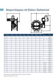
Dimensions L1 and L2 in mm<br />
DN<br />
40<br />
L1 Standard socket 161<br />
Long socket 200<br />
L 2<br />
169<br />
208<br />
Block strapping Gasket Gliding ring Locking ring Screw ring<br />
L 1 L 2<br />
L 1<br />
164<br />
203<br />
Insert Screw ring, locking ring, gliding ring and gasket in this sequence behind the centre punch<br />
marking L 2. Lubricate the pipe end, face of gasket, gliding ring and locking ring as well as the<br />
face and the screw thread of the screw ring with the lubricant supplied by the pipe manufacturer.<br />
Insert pipe end into the socket, centre it and check the installation depth L 1.<br />
Do not remove lifting gear yet.<br />
50<br />
L 2<br />
172<br />
211<br />
L 1<br />
170<br />
209<br />
65<br />
L 2<br />
178<br />
217<br />
Impress gasket with inserting device evenly into the socket (centering). Push gliding ring and<br />
locking ring until the gliding ring touches the gasket. Screw down screw ring with a hammer or<br />
ram as tighten as there is no turning of the screw ring possible anymore.<br />
100 mm<br />
Block strapping<br />
Check the correct installation depth:<br />
Block strapping must be within L2 ± 3 mm.<br />
After installation of the connection in centrical position, pipes can be deviated<br />
DN 80 – 200 up to 3 ° and<br />
DN 250 – 400 up to 2 °<br />
6239