1 Experiment #2: Telescopes And Microscopes Purpose: To ...
1 Experiment #2: Telescopes And Microscopes Purpose: To ...
1 Experiment #2: Telescopes And Microscopes Purpose: To ...

Create successful ePaper yourself
Turn your PDF publications into a flip-book with our unique Google optimized e-Paper software.
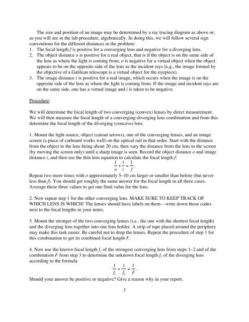
The size and position of an image may be determined by a ray tracing diagram as above or,<br />
as you will see in the lab procedure, algebraically. In doing this, we will follow several sign<br />
conventions for the different distances in the problem:<br />
1. The focal length f is positive for a converging lens and negative for a diverging lens.<br />
2. The object distance o is positive for a real object, that is if the object is on the same side of<br />
the lens as where the light is coming from; o is negative for a virtual object when the object<br />
appears to be on the opposite side of the lens as the incident rays (e.g., the image formed by<br />
the objective of a Galilean telescope is a virtual object for the eyepiece).<br />
3. The image distance i is positive for a real image, which occurs when the image is on the<br />
opposite side of the lens as where the light is coming from. If the image and incident rays are<br />
on the same side, one has a virtual image and i is taken to be negative.<br />
Procedure:<br />
We will determine the focal length of two converging (convex) lenses by direct measurement.<br />
We will then measure the focal length of a converging-diverging lens combination and from this<br />
determine the focal length of the diverging (concave) lens.<br />
1. Mount the light source, object (cutout arrows), one of the converging lenses, and an image<br />
screen (a piece of carboard works well) on the optical rail in that order. Start with the distance<br />
from the object to the lens being about 20 cm, then vary the distance from the lens to the screen<br />
(by moving the screen only) until a sharp image is seen. Record the object distance o and image<br />
distance i, and then use the thin lens equation to calculate the focal length f:<br />
1 1 1<br />
+ =<br />
o i f .<br />
Repeat two more times with o approximately 5–10 cm larger or smaller than before (but never<br />
less than f). You should get roughly the same answer for the focal length in all three cases.<br />
Average these three values to get one final value for the lens.<br />
2. Now repeat step 1 for the other converging lens. MAKE SURE TO KEEP TRACK OF<br />
WHICH LENS IS WHICH! The lenses should have labels on them—write down those codes<br />
next to the focal lengths in your notes.<br />
3. Mount the stronger of the two converging lenses (i.e., the one with the shortest focal length)<br />
and the diverging lens together into one lens holder. A strip of tape placed around the periphery<br />
may make this task easier. Be careful not to drop the lenses. Repeat the procedure of step 1 for<br />
this combination to get its combined focal length F.<br />
4. Now use the known focal length f1 of the strongest converging lens from steps 1–2 and of the<br />
combination F from step 3 to determine the unknown focal length f2 of the diverging lens<br />
according to the formula<br />
1<br />
+<br />
f1 1<br />
=<br />
f2 1<br />
F .<br />
Should your answer be positive or negative? Give a reason why in your report.<br />
3