1 Experiment #2: Telescopes And Microscopes Purpose: To ...
1 Experiment #2: Telescopes And Microscopes Purpose: To ...
1 Experiment #2: Telescopes And Microscopes Purpose: To ...

You also want an ePaper? Increase the reach of your titles
YUMPU automatically turns print PDFs into web optimized ePapers that Google loves.
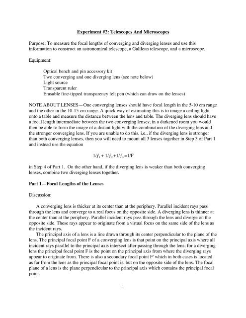
<strong>Experiment</strong> <strong>#2</strong>: <strong>Telescopes</strong> <strong>And</strong> <strong>Microscopes</strong><br />
<strong>Purpose</strong>: <strong>To</strong> measure the focal lengths of converging and diverging lenses and use this<br />
information to construct an astronomical telescope, a Galilean telescope, and a microscope.<br />
Equipment:<br />
Optical bench and pin accessory kit<br />
Two converging and one diverging lens (see note below)<br />
Light source<br />
Transparent ruler<br />
Erasable fine-tipped transparency felt pen (which can draw on the lenses)<br />
NOTE ABOUT LENSES—One converging lenses should have focal length in the 5-10 cm range<br />
and the other in the 10-15 cm range. A quick way of estimating this is to image a ceiling light<br />
onto a table and measure the distance between the lens and table. The diverging lens should have<br />
a focal length intermediate between the two converging lenses; in a darkened room you would<br />
then be able to form the image of a distant light with the combination of the diverging lens and<br />
the stronger converging lens. If you are unable to do this, i.e., if the diverging lens is stronger<br />
than both converging lenses, then you will need to mount all 3 lenses together in Step 3 of Part 1<br />
and instead use the equation<br />
1/ƒ 1 + 1/ƒ 2 +1/ƒ 3 =1/F<br />
in Step 4 of Part 1. On the other hand, if the diverging lens is weaker than both converging<br />
lenses, combine two diverging lenses together.<br />
Part 1—Focal Lengths of the Lenses<br />
Discussion:<br />
A converging lens is thicker at its center than at the periphery. Parallel incident rays pass<br />
through the lens and converge to a real focus on the opposite side. A diverging lens is thinner at<br />
the center than at the periphery. Parallel incident rays pass through the lens and diverge on the<br />
opposite side. These rays appear to originate from a virtual focus on the same side of the lens as<br />
the incident rays.<br />
The principal axis of a lens is a line drawn through its center perpendicular to the plane of the<br />
lens. The principal focal point F of a converging lens is that point on the principal axis where all<br />
incident rays parallel to the principal axis intersect after passing through the lens; for a diverging<br />
lens the principal focal point F is the point on the principal axis from where the diverging rays<br />
appear to originate from. There is also a secondary focal point F' which in both cases is located<br />
as far from the lens as the principal focal point is, but on the opposite side of the lens. The focal<br />
plane of a lens is the plane perpendicular to the principal axis which contains the principal focal<br />
point.<br />
1
The focal length f of a lens is the distance along the principal axis from the center of the lens<br />
to its principal focal point. The power of a lens, measured in diopters, is the reciprocal of the<br />
focal length in meters, i.e., D 1/f.<br />
The location and size of an image may be determined by tracing rays from points on the<br />
object to corresponding points on the image. It is enough to use two rays from any point on the<br />
object to locate the position of its image. The procedure is slightly different depending on<br />
whether you are using a converging or a diverging lens—see Fig. 1(a)–(b). The object distance o<br />
is defined to be the distance from the object to the center of the lens, while the image distance i is<br />
the distance from the center of the lens to the image.<br />
From any point on the object, ray 1 is drawn parallel to the principal axis. For a converging<br />
lens, the ray is refracted by the lens and passes through the principal focal point F on the other<br />
side of the lens. For a diverging lens, the ray diverges after emerging from the lens, as if it were<br />
coming from the principal focal point F on the incident side of the lens. Ray 2 from the object<br />
point is drawn so that it passes through the center of the lens undeflected in both cases.<br />
If the two rays intersect after they emerge from the lens, the point of intersection is a real<br />
image of the object point, which means that the image may be seen on a screen placed at that<br />
point. If they are diverging after they emerge from the lens, then imagine projecting the rays<br />
backward through the lens until they intersect. This point, from which the rays seem to be<br />
emerging, is the position of the virtual image. The virtual image can be seen through the lens by<br />
an observer but cannot be captured on a screen.<br />
lens<br />
object 2<br />
F<br />
object<br />
2<br />
F<br />
F'<br />
1<br />
Fig. 1(a). Converging lens with o > f<br />
1<br />
virtual image<br />
lens<br />
Fig. 1(b). Diverging lens with o > |f|<br />
2<br />
real image<br />
F' principal<br />
axis
The size and position of an image may be determined by a ray tracing diagram as above or,<br />
as you will see in the lab procedure, algebraically. In doing this, we will follow several sign<br />
conventions for the different distances in the problem:<br />
1. The focal length f is positive for a converging lens and negative for a diverging lens.<br />
2. The object distance o is positive for a real object, that is if the object is on the same side of<br />
the lens as where the light is coming from; o is negative for a virtual object when the object<br />
appears to be on the opposite side of the lens as the incident rays (e.g., the image formed by<br />
the objective of a Galilean telescope is a virtual object for the eyepiece).<br />
3. The image distance i is positive for a real image, which occurs when the image is on the<br />
opposite side of the lens as where the light is coming from. If the image and incident rays are<br />
on the same side, one has a virtual image and i is taken to be negative.<br />
Procedure:<br />
We will determine the focal length of two converging (convex) lenses by direct measurement.<br />
We will then measure the focal length of a converging-diverging lens combination and from this<br />
determine the focal length of the diverging (concave) lens.<br />
1. Mount the light source, object (cutout arrows), one of the converging lenses, and an image<br />
screen (a piece of carboard works well) on the optical rail in that order. Start with the distance<br />
from the object to the lens being about 20 cm, then vary the distance from the lens to the screen<br />
(by moving the screen only) until a sharp image is seen. Record the object distance o and image<br />
distance i, and then use the thin lens equation to calculate the focal length f:<br />
1 1 1<br />
+ =<br />
o i f .<br />
Repeat two more times with o approximately 5–10 cm larger or smaller than before (but never<br />
less than f). You should get roughly the same answer for the focal length in all three cases.<br />
Average these three values to get one final value for the lens.<br />
2. Now repeat step 1 for the other converging lens. MAKE SURE TO KEEP TRACK OF<br />
WHICH LENS IS WHICH! The lenses should have labels on them—write down those codes<br />
next to the focal lengths in your notes.<br />
3. Mount the stronger of the two converging lenses (i.e., the one with the shortest focal length)<br />
and the diverging lens together into one lens holder. A strip of tape placed around the periphery<br />
may make this task easier. Be careful not to drop the lenses. Repeat the procedure of step 1 for<br />
this combination to get its combined focal length F.<br />
4. Now use the known focal length f1 of the strongest converging lens from steps 1–2 and of the<br />
combination F from step 3 to determine the unknown focal length f2 of the diverging lens<br />
according to the formula<br />
1<br />
+<br />
f1 1<br />
=<br />
f2 1<br />
F .<br />
Should your answer be positive or negative? Give a reason why in your report.<br />
3
Part 2—Construction of <strong>Telescopes</strong> and <strong>Microscopes</strong><br />
Discussion:<br />
We will first discuss the most basic optical instrument, the “magnifying glass,” also called a<br />
“simple magnifier.” The normal human eye can focus a sharp image of an object on the retina if<br />
the object is located anywhere from infinity (such as stars) to a certain point called the near point<br />
N. The standard distance n to the near point is taken in textbooks to be 25 cm. However, for most<br />
young people like yourselves, n is shorter than that, as we will determine by direct measurement.<br />
The retinal image of an object closer to the eye than the near point is fuzzy. If an object of height<br />
h o is placed at the near point then the angle (in radians) subtended by it at the eye is<br />
as can be seen from Fig. 2.<br />
eye<br />
tan = h o<br />
n<br />
Fig. 2. Maximum magnification of the naked eye.<br />
Assuming that h o
But from the similar triangles in this figure, we see that<br />
hi =<br />
ho i i<br />
so that <br />
o f ho f .<br />
The angular magnification is defined as the increase in angular size,<br />
m n<br />
=<br />
f .<br />
Since a realistic lower limit on the focal length is a few centimeters in order to avoid getting<br />
aberrations, simple magnifiers typically have magnifications no greater than 10.<br />
The simple telescopes and microscope which you will build here are basically two-lens<br />
optical systems, in which a converging lens (the objective) is used to form a real image of the<br />
object, whether it be a tiny bug or a distant planet. A second lens called the eyepiece, which can<br />
be either converging or diverging, is then used to examine the image formed by the objective.<br />
In an astronomical (or Newtonian) telescope, the objective (“obj”) forms a real inverted<br />
image I of a distant object O (such that o ) in its focal plane, as shown in Fig. 4 below. The<br />
angular size of the image formed by the objective is given by<br />
obj hi fobj where hi is the height of the image and fobj is the focal length of the objective. This is also the<br />
angular size of the distant object, as we see in the following diagram.<br />
h o<br />
large distant<br />
object<br />
obj<br />
h i'<br />
inverted virtual<br />
distant image<br />
objective<br />
obj<br />
Fig. 4. Astronomical Telescope<br />
The image I of the objective is the real object O' of height h o' = h i for the eyepiece, which is used<br />
as a simple magnifier. The eyepiece then produces (as in Fig. 3) a virtual image I' which is<br />
magnified in size to h i' but remains inverted. The angular size of the image seen through the<br />
eyepiece (“eye”) is seen from Fig. 4 to be<br />
eye h i<br />
f eye<br />
where f eye is the focal length of the eyepiece. The image I formed by the objective is very near the<br />
focal point of the eyepiece, so that the distance L between the two lenses is approximately equal<br />
to the sum of their focal lengths, L = f obj + f eye. The total angular magnification of the telescope is<br />
M eye<br />
obj<br />
5<br />
f obj<br />
= f obj<br />
f eye<br />
f eye<br />
eye<br />
h i = h o'<br />
eye<br />
eyepiece<br />
eye
and evidently the objective must be weaker (i.e., have a longer focal length) than the eyepiece in<br />
order to give magnification (M > 1).<br />
The astronomical telescope produces an inverted image, which is okay for looking at stars<br />
but inconvenient for use on land. So for the latter purpose, a terrestial (or Galilean) telescope can<br />
be employed instead, resulting in an erect image. A terrestial telescope is constructed using a<br />
diverging lens for the eyepiece rather than a converging lens, as shown in Fig. 5 below.<br />
objective<br />
f obj<br />
Fig. 5. Terrestial telescope<br />
This figure assumes that you are looking at an object which is very far away (i.e., near infinity so<br />
that the incoming rays are very nearly parallel). The resulting image is also at infinity, which<br />
corresponds to the relaxed eye position. Note that f obj > 0 for the converging objective lens, while<br />
f eye < 0 for the diverging eyepiece. The total angular magnification of the telescope is, just as for<br />
the astronomical telescope,<br />
M = f obj<br />
f eye<br />
so that we again require the objective to be weaker (i.e., have a longer focal length) than the<br />
eyepiece in order to give magnification. Also, the distance L between the two lenses is again<br />
approximately equal to the sum of their focal lengths, but since f eye < 0, this means that the lens<br />
separation equals the difference in the absolute values of their focal lengths, L = |f obj| – |f eye|. Thus,<br />
an added advantage of the terrestial telescope is that it is more compact than the astronomical<br />
telescope.<br />
Finally, in a microscope a small object is placed near, but just beyond, the focal point of the<br />
objective so that an enlarged, real, inverted image I is formed, which becomes a real object O' for<br />
the eyepiece. The eyepiece then acts as a simple magnifier, as in the astronomical telescope, to<br />
produce a final image I' which remains inverted—cf. Fig. 6 below. If s is the distance between<br />
the focal points F obj and F eye', while h o and h i are the heights of the object and image produced by<br />
the objective, then the lateral magnification of the objective is<br />
m obj h i<br />
h o<br />
6<br />
= s<br />
f obj<br />
eyepiece<br />
f eye<br />
eye
ased on the similar triangles in Fig. 6. The total magnification of the microscope is the product<br />
of the lateral magnification m obj of the objective and the angular magnification m eye = n/f eye of the<br />
eyepiece (as in Fig. 3),<br />
M m obj m eye = s<br />
f obj<br />
n<br />
f eye<br />
7<br />
= (L f obj f eye )n<br />
f obj f eye<br />
where, as for the telescopes, L is the distance between the lenses.<br />
Procedure:<br />
f obj<br />
ho small<br />
object<br />
objective<br />
inverted virtual<br />
distant image<br />
f obj s<br />
obj hi = ho' eye h i'<br />
obj<br />
Fig. 6. Microscope<br />
eyepiece<br />
1. Build an astronomical telescope using the two converging lenses from part 1 of this lab<br />
separated by a distance equal to the sum of their focal lengths. Use the stronger lens as the<br />
eyepiece. Bring your eye up close to the eyepiece and look through it at a distant object; it should<br />
appear inverted. If you normally wear glasses, keep your glasses on. Slightly adjust the distance<br />
between the two lenses to focus the telescope. (Note: If your eye is too far from the eyepiece,<br />
you can get fooled into thinking the various instruments constructed in this lab are focused when<br />
they actually are not.)<br />
2. Determine the experimental magnification of your telescope by looking at two parallel lines<br />
which you have drawn on the blackboard across the room. Hold up a ruler at about arm’s length<br />
(but not so far that you cannot read the scale!), look through the telescope with one eye, and<br />
measure the apparent spacing between the two lines with your other eye. (If you cross your eyes<br />
you may be able to overlap the two images, making this task easier.) Now move your head<br />
slightly so that you are looking at the two lines with your naked eye, and again measure the<br />
apparent spacing between the two lines without changing the distance from the ruler to your eye.<br />
The ratio of the spacings measured with and without the telescope is the experimental<br />
magnification. Compare the result to the theoretical magnification which equals the absolute<br />
value of the ratio of the two focal lengths of the lenses. (Accuracies are not really good enough<br />
to warrant a calculation of percent error. Instead discuss in your report whether the agreement<br />
seems reasonable and why the accuracy isn’t expected to be terribly high.) What happens if you<br />
turn the telescope around and look through the wrong end of it? Explain why this happened in<br />
your report.<br />
f eye<br />
eye
3. Next, build a terrestial telescope by using the weaker of your two converging lenses as the<br />
objective and the diverging lens as the eyepiece, separating the two lenses by the difference in<br />
the absolute values of their focal lengths. Again bring your eye up close to the eyepiece and look<br />
through it at a distant object, and slightly adjust the distance between the two lenses to focus the<br />
telescope. This time things should appear upright.<br />
4. Repeat step 2 for your terrestial telescope.<br />
5. Finally, build a microscope according to the following procedure using the two converging<br />
lenses but now the objective should be the strongest lens, unlike for the two telescopes. First<br />
mount the ruled translucent scale a few centimeters beyond the (secondary) focal point of the<br />
objective lens, to serve as an object to examine; measure the distance o between this object and<br />
the objective. Then use the thin lens equation<br />
1 1i 1<br />
+ =<br />
o fobj to compute the distance i from the objective to the image produced by it. Now position the<br />
eyepiece at a distance from the objective equal to i + f eye. Finally, bring your eye up close to the<br />
eyepiece (with your glasses on) and slightly adjust the position of the ruled scale until you see a<br />
focused image of it. (You and your partner may have to each do this separately, since your eyes<br />
may be slightly different.) Note that the microscope will invert the image relative to the object.<br />
6. Determine the experimental magnification of your microscope as follows. Look at an adjacent<br />
pair of rulings on the object screen through the microscope, back your eye up slightly, and use a<br />
felt pen to mark the apparent positions of the two rulings directly on the eyepiece lens. Now<br />
measure the separation between your two marks with a ruler. Also measure the actual separation<br />
between the two rulings on the screen. The ratio of these two separations is the magnification.<br />
7. <strong>To</strong> get the theoretical magnification of the microscope, first measure your near point distance.<br />
<strong>To</strong> do so, hold up a plastic ruler to the bridge of your nose with the zero end at your nose.<br />
Gradually bring a small object which has writing on it along the ruler toward your eye (with your<br />
glasses on). Find the shortest distance at which you can still comfortably focus on the writing<br />
(i.e., without having to strain so much that you get a headache: be reasonable!). Use your near<br />
point distance n to compute the theoretical magnification as M = (L f o f e ) n /( f o f e )<br />
where L is the measured distance between the two lenses. Compare to the experimental<br />
magnification found in step 6.<br />
Supplementary Problem:<br />
A converging lens and a diverging lens both have a focal length whose absolute value is 10 cm<br />
and they are separated from each other by 10 cm. An object is placed 15 cm away from the<br />
diverging lens (i.e., 25 cm away from the converging lens). Where is the image formed by the<br />
converging lens located? Is it real or virtual? Is it erect or inverted? How many times bigger or<br />
smaller is it than the object (i.e., what is the magnification)?<br />
8