Lock-N-Load AP - Hornady
Lock-N-Load AP - Hornady
Lock-N-Load AP - Hornady

Create successful ePaper yourself
Turn your PDF publications into a flip-book with our unique Google optimized e-Paper software.
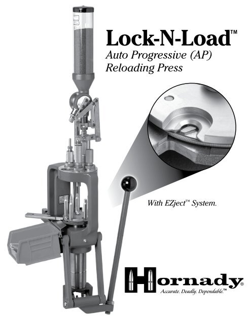
<strong>Lock</strong>-N-<strong>Load</strong>TM<br />
Auto Progressive (<strong>AP</strong>)<br />
Reloading Press<br />
With EZject System.
Table of ConTenTs<br />
Steps<br />
Page<br />
Overview 2<br />
Tools needed for assembly and set up 2<br />
1: Mounting the <strong>Lock</strong>-N-<strong>Load</strong> Auto Progressive 3<br />
2: Determine which shell plate is required for your application 4<br />
2A: Installing the Shell Plate 5<br />
2B: Removing the Shell Plate 6<br />
3: Operation of your <strong>Lock</strong>-N-<strong>Load</strong> Auto Progressive Press 8<br />
4: Automatic Primer Feed Assembly 9<br />
4A: Installing the Primer Body 9<br />
4B: Installing the Primer Slide, Large or Small 9<br />
4C: Installing the Primer Punch Assembly, Large or Small 9<br />
4D: Installing the Primer Tubes 9<br />
4E: Installing the Primer Tube Housing 9<br />
4F: Primer Tube Support Installation 10<br />
5: <strong>Load</strong>ing the Primer Tube 11<br />
6: Changing Primer Tubes 12<br />
7: Automatic Primer Feed Inspection 13<br />
8: Installing the Deluxe Powder Measure with Case Activated Powder Drop 13<br />
9: <strong>Lock</strong>-N-<strong>Load</strong> quick change bushing system 14<br />
10: Die Mounting Instructions 15<br />
11: Preparing to <strong>Load</strong> 16<br />
12: Adjusting the Auto Advance Mechanism 17<br />
Maintenance of the <strong>Lock</strong>-N-<strong>Load</strong> A/P 19<br />
Tips for a Trouble Free Operation 19<br />
Optional Accessories for your L-N-L <strong>AP</strong> 20<br />
List of Illustrations<br />
Figures<br />
1. <strong>AP</strong> Mounting 3<br />
2. Installing Shell Plate 5<br />
3. Removing Shell Plate 6<br />
4. Primer Feed System 10<br />
5. Filling the Priming System 11<br />
6. <strong>Lock</strong>-N-<strong>Load</strong> Powder Measure 13<br />
7. <strong>Hornady</strong> <strong>Lock</strong>-N-<strong>Load</strong> System 14<br />
8. Pawl Adjustment 17<br />
Charts<br />
1. Shell Plate Selection Chart 4<br />
2. Trouble Free Operation 19<br />
3. Bill of Materials 21<br />
4. Exploded View 22<br />
- 1 -
overview<br />
<strong>Hornady</strong> ®<br />
<strong>Lock</strong>-N-<strong>Load</strong> Auto Progressive<br />
Your new <strong>Lock</strong>-N-<strong>Load</strong> Auto Progressive (A/P) reloading press has been packaged to insure minimal vibration and<br />
damage during transportation.<br />
Remove all the parts from the packing box and spread them out over a large flat surface. Refer to the parts list on<br />
pages 21 and 22 and check to make sure all necessary parts are identified.<br />
The manual provides step-by-step instructions and suggestions that make set-up and operation easy and<br />
understandable.<br />
If at any time during operation you feel like you are forcing the press, stop and identify the problem. Do not force<br />
anything, because damage will occur. Powders and Primers are explosive if handled carelessly! Always work slowly<br />
and carefully without distractions and wear eye protection. Try to avoid touching primers with oily fingers. The oil on<br />
your fingers may contaminate the primers and cause them to misfire.<br />
Tools needed for assembly and set-up:<br />
7⁄16" End Wrench<br />
(2) 1⁄2" End Wrenches<br />
15⁄16" End Wrench<br />
3⁄32" Hex Wrench (included)<br />
1/8" Hex Wrench (included)<br />
5⁄32" Hex Wrench<br />
Needle Nose Pliers<br />
Electric Drill<br />
5/16" Hex Wrench<br />
- 2 -
insTruCTions<br />
Step 1: Mounting the <strong>Lock</strong>-N-<strong>Load</strong> Auto Progressive<br />
Your work area should be well lit and have plenty of room for your reloading accessories. Your <strong>Hornady</strong><br />
<strong>Lock</strong>-N-<strong>Load</strong> <strong>AP</strong> should be mounted securely 2 1/4 " from the edge of a solid level bench. (Check for obstructions<br />
on or below the bench before you drill any holes.)<br />
Mount the press using (2) 5/16" bolts that are long enough to secure the press to the bench with plenty of<br />
clearance for the nuts. (Due to variation of benches these bolts are not provided.) We also recommend using<br />
5/16" flat washers top and bottom, in addtion to lock washers on the bottom side.<br />
Insert and secure the right-hand mounting bolt first. Next, insert and secure the left-hand bolt, placing the<br />
cartridge catcher bracket (13) underneath the bolt head and washer before tightening.<br />
Thread the press Handle (44) into the Toggle (39) at the bottom of the press and tighten the Jam Nut (43)<br />
using a 15/16" wrench.<br />
5/16 BOLT<br />
5/16 FLAT WASHER<br />
CARTRIDGE CATCHER BRACKET (13)<br />
Figure 1: <strong>AP</strong> Mounting<br />
- 3 -<br />
JAM NUT (43)<br />
TOGGLE (39)
* <strong>Hornady</strong> shell plates that are sold in the plastic boxes are the only ones that will fit<br />
the <strong>AP</strong> Press with EZject System. These shell plates (which are sold separately) are<br />
manufactured with a groove on the bottom side.<br />
shell PlaTes<br />
Step 2: Determine which shell plate is required for your application<br />
See Chart 1 below to help with this selection.<br />
SHELL PLATE NO. 1<br />
Item No. 392601<br />
5.6x57<br />
22/250 Rem<br />
22-250 Ack Imp<br />
240 Wby.<br />
243 Win.<br />
244/6MM Rem<br />
6MM Int.<br />
6MM/284<br />
6MM Rem Br<br />
250 Sav..<br />
25/06 Rem<br />
257 Rbts..<br />
25/284<br />
260 Rem<br />
6.5 Rem Mag<br />
6.5/06<br />
6.5 x 57<br />
6.5/284<br />
6.5 Creedmoor<br />
270 Win.<br />
7x57 (7MM mau.)<br />
7MM/08<br />
7MM Rem. BR<br />
7x64<br />
7MM Exp/280<br />
280 Rem<br />
280 Rem Ack Imp<br />
284 Win.<br />
300 Sav.<br />
308 Win.<br />
30 TC<br />
30/06 Springfield<br />
338 Federal<br />
7.7 Jap.<br />
7.92x33MM Kurz<br />
8MM Mau.<br />
8MM /06<br />
8x60 S<br />
338-06<br />
35 Whelen<br />
358 Win.<br />
9.3x57<br />
9.3x62<br />
400 Cor-bon<br />
44 Auto Mag.<br />
45 Win Mag<br />
458 SOCOM.<br />
450 Bushmaster<br />
SHELL PLATE NO. 2<br />
Item No. 392602<br />
219 Zipper<br />
5.6x52R<br />
22 Sav. HP<br />
25/35 Win<br />
7x30 Waters<br />
30/30Win<br />
30/30 Ack Imp<br />
30 Herrett<br />
32 Win. Spl.<br />
8.15x46 R<br />
357 Herrett<br />
38-55 Win<br />
375 Win<br />
7.5 Swiss<br />
32/40 Win<br />
357 Herrett<br />
38-55 Win<br />
375 Win<br />
7.5 Swiss<br />
32/40 Win<br />
SHELL PLATE NO. 3<br />
Item No. 392603<br />
22 Hornet<br />
22-K Hornet<br />
270 Rem<br />
SHELL PLATE NO. 4<br />
Item No. 392304<br />
220 Swift<br />
225 Winchester<br />
6.5 JDJ<br />
7MM Merrill<br />
30MM Merrill<br />
SHELL PLATE NO. 5<br />
Item No. 392605<br />
257 Wby. Mag.<br />
6.5 Rem. Mag.<br />
264 Win. Mag.<br />
270 Wby. Mag.<br />
7MM Rem. Mag.<br />
7MM Rem SA Ultra Mag.<br />
7MM Wby. Mag.<br />
7MM Rem. Ultra Mag.<br />
7MM STW<br />
300 H&H<br />
300 Win. Mag.<br />
300 Wby. Mag.<br />
300 Rem. SA UI. Mag.<br />
300 Rem. UI. Mag<br />
308 Norma Mag.<br />
8MM Rem. Mag.<br />
338 Win. Mag.<br />
338 Rem. Ultra Mag.<br />
340 Wby. Mag.<br />
350 Rem. Mag.<br />
358 Norma Mag.<br />
375 Rem. Ultra Mag.<br />
375 H&H<br />
416 Rem. Mag.<br />
458 Win.<br />
450 Marlin<br />
300 RCM<br />
338 RCM<br />
375 Ruger<br />
416 Ruger<br />
458 Lott<br />
SHELL PLATE NO. 6<br />
Item No. 392606<br />
22 PPC<br />
22 RCFM-Jet<br />
256 Win.<br />
6MM PPC<br />
7.62x39<br />
38/357/357 Max.<br />
SHELL PLATE NO. 7<br />
Item No. 392607<br />
218 Bee<br />
25/20 Win.<br />
32/20 Win.<br />
SHELL PLATE NO. 8<br />
Item No. 392608<br />
30 Luger<br />
30 Mauser<br />
9MM Luger<br />
9x21<br />
9x18 Makarov<br />
38 Super Auto<br />
9x23<br />
SHELL PLATE NO. 9<br />
Item No. 392609<br />
38/40 Win.<br />
44/40 Win.<br />
SHELL PLATE NO. 10<br />
Item No. 392610<br />
357 Sig<br />
40 S&W<br />
10MM Auto<br />
SHELL PLATE NO. 11<br />
Item No. 392611<br />
303 British<br />
30/40 Krag<br />
- 4 -<br />
SHELL PLATE NO. 12<br />
Item No. 392612<br />
25 Rem.<br />
6.8 Rem. SPC<br />
30 Rem.<br />
32 Rem.<br />
SHELL PLATE NO. 13<br />
Item No. 392613<br />
7X65 R<br />
7x57 R<br />
9.3x74 R<br />
SHELL PLATE NO. 14<br />
Item No. 392614<br />
30/378 Wby. Mag.<br />
33 Win.<br />
338/378 Wby.<br />
378 Wby. Mag.<br />
416 Wby. Mag.<br />
460 Wby. Mag.<br />
45/70 Govt.<br />
480 Ruger/475 Linebaugh<br />
SHELL PLATE NO. 16<br />
Item No. 392616<br />
17 Rem.<br />
17 Rem. Fireball<br />
17/222<br />
17/223<br />
220 VT<br />
20 Tactical<br />
204 Ruger<br />
221 Rem.<br />
222 Rem.<br />
222 Rem. Mag.<br />
5.6x50 Mag<br />
223 Rem.<br />
6MM/223<br />
6x47 Rem<br />
6MM TCU<br />
6.5MM TCU<br />
7MM TCU<br />
7MM/223 Ingram<br />
7x47 Helm<br />
380 Auto<br />
TOP SIDE BOTTOM SIDE<br />
SHELL PLATE NO. 19<br />
Item No. 392619<br />
6.5 x 55 Scand (Swedish)<br />
SHELL PLATE NO. 22<br />
Item No. 392622<br />
5.7 Johnson Spitfire<br />
30 M1 Carbine<br />
32 ACP<br />
SHELL PLATE NO. 23<br />
Item No. 392623<br />
7.62 Russian<br />
SHELL PLATE NO. 27<br />
Item No. 392627<br />
308 Marlin Express<br />
309 JDJ<br />
375 JDJ<br />
444 Marlin<br />
SHELL PLATE NO. 28<br />
Item No. 392628<br />
38 S&W<br />
SHELL PLATE NO. 29<br />
Item No. 392629<br />
41 Mag<br />
SHELL PLATE NO. 30<br />
Item No. 392630<br />
6.5x68<br />
8x68 S<br />
357/44 B&D<br />
44 Spl./44 Mag.<br />
445 Sup Mag<br />
7.5 Swiss<br />
SHELL PLATE NO. 31<br />
Item No. 392631<br />
45 Auto Rim<br />
SHELL PLATE NO. 32<br />
Item No. 392632<br />
45 Colt<br />
454 Casull<br />
SHELL PLATE NO. 33<br />
Item No. 392633<br />
303 Sav.<br />
307 Win.<br />
356 Win.<br />
SHELL PLATE NO. 35<br />
Item No. 392635<br />
223 WSSM<br />
243 WSSM<br />
25 WSSM<br />
270 WSSM<br />
7x61 S&H<br />
7MM WSM<br />
300 WSM<br />
325 WSM<br />
SHELL PLATE NO. 36<br />
Item No. 392636<br />
32 S&W Long/Short/H&R<br />
SHELL PLATE NO. 40<br />
Item No. 392640<br />
50 A&E<br />
SHELL PLATE NO. 44<br />
Item No. 392644<br />
500 S&W<br />
SHELL PLATE NO. 45<br />
Item No. 392645<br />
45 ACP (ONLY)<br />
SHELL PLATE NO. 46<br />
Item No. 392646<br />
460 S&W<br />
SHELL PLATE NO. 51<br />
Item No. 392651<br />
455 Webley<br />
<strong>Hornady</strong> Shell<br />
Plates are sold<br />
separately.
2: Installing the Shell Plate<br />
Raise the Ram approximately 2" and place Block under Sub Plate (24). This disengages the Index Pawls (32),<br />
and allows for free rotation of the Shell plate.<br />
Put a small amount of general-purpose grease on the Shell Plate Ball Detents located on bottom side of Shell<br />
Plate (12), and on the top surface of the Sub-Plate (24).<br />
Align the Shell Plate* with the keyed Drive Hub (29).<br />
Place the 3/8" Shell Plate Retainer Bolt (9) thru the 3/8" Flat Washer (28), (large end up) and thread the bolt<br />
into the Drive Hub (29).<br />
Tighten the bolt (9) using a 5/16" Allen wrench, only tight enough to prevent it from coming loose.<br />
Stretch the Case Retainer Spring (17) over the top of the Shell Plate (12).<br />
Remove Block from under Sub-Plate (24) and make sure it is in the Retainer Spring Grove (17A).<br />
While cycling the Press, push the Case Retainer Spring (17) into the relieved area on the Sub-Plate (24). You<br />
will have to cycle the press a couple of stations to receive these results.<br />
EZject<br />
Figure 2: Installing Shell Plate<br />
- 5 -<br />
SHELL PLATE RETAINER BOLT (9)<br />
FLAT WASHER (28)<br />
SHELL PLATE (12)<br />
RETAINER SPRING-<br />
GROOVE (17A)<br />
DRIVE HUB (29)<br />
SUB PLATE (24)
Check to make sure the Drive Pawls (32) are properly timed, by cycling the press with the handle. A properly<br />
timed press will rotate the Shell Plate so the Ball Detents on the Shell Plate always engage the recesses in<br />
the Sub Plate.<br />
When properly adjusted, it is not necessary to assist the Shell Plate to rotate into the Detents, and you should<br />
not feel a double click on the handle of the press as it indexes. (If the adjustment is too long it is normally felt<br />
as a double click on the handle of the press. You may have to cycle the press very slowly to feel this.) The pawl<br />
engagement is set at the factory and very seldom requires adjustment by the user.<br />
STATION 1<br />
STATION 5<br />
SHELL PLATE RETAINER BOLT (9)<br />
FLAT WASHER (28)<br />
2B: Removing the Shell Plate<br />
Use a 5/16" Allen wrench to remove the Bolt (9) and to remove the shell plate.<br />
Remove the Case Retainer Spring (17).<br />
Figure 3: Removing Shell Plate<br />
STATION 2<br />
- 6 -<br />
STATION 3<br />
STATION 4<br />
LEFT PAWL RIGHT PAWL<br />
PAWL<br />
ADJUSTMENT<br />
SCREW
shell PlaTe TroubleshooTing<br />
If the timing is severely out of adjustment, the Index Pawls (32) may have been damaged as outlined on page 6.<br />
If the Shell Plate does not rotate freely after mounting, check for these conditions:<br />
• You may be trying to use the wrong version of shell plate. Your shell plate must have a groove cut on the<br />
bottom side.<br />
• Dirt or debris between the shell plate and the drive hub.<br />
• The Ball Detent bodies are not below flush on the underside of the Shell Plate.<br />
• The Shell Plate is warped or damaged.<br />
If you reach a point where you cannot get the press to work, please call our technical service staff at<br />
800-338-3220 or email webmaster@hornady.com.<br />
- 7 -
Step 3: Operation of your <strong>Lock</strong>-N-<strong>Load</strong> Auto Progressive Press<br />
The <strong>Hornady</strong> <strong>Lock</strong>-N-<strong>Load</strong> <strong>AP</strong> utilizes a high strength aluminum alloy frame with a compound linkage system<br />
which operates the 2" diameter cylindrical ram. The Ram houses a drive shaft that is attached to the shell<br />
plate at the upper end and the index wheel at the lower end. The toggle contains two spring actuated pawls<br />
which alternately engage the index wheel to advance the shell plate through the different reloading stations.<br />
As the handle is lowered, the right Pawl contacts the Index Wheel, advancing the Shell Plate during the first<br />
1 1/2" of upward travel of the Ram. With this upward travel, the cases become aligned with the dies at the top<br />
of the Press. As the Shell Plate comes to the top of the press, it guides the cartridge cases into the five die<br />
stations to perform the reloading operations except priming.<br />
The handle is then raised to complete the stroke, lowering the Shell Plate. When the Shell Plate comes to within<br />
1 3/4" of the bottom, the left Pawl engages the Index Wheel which advances the Shell Plate into position over<br />
the primer to seat it into the case that was just sized and de-primed. Pushing back on the handle with<br />
moderate force will seat the new primer into the case.<br />
Once the dies are in place, and all stations are filled, the proper sequence for reloading is listed below.<br />
Place an empty case into station one. (Using the optional LNL-<strong>AP</strong> Casefeeder, this step is automatically done<br />
for you.)<br />
Insert bullet into the powder charged case in station four.<br />
Lower the handle.<br />
Powder drops into the newly primed case at station three.<br />
Raise the handle and seat a new primer in the de-primed case that has now moved to station two.<br />
<strong>Load</strong>ed cartridge is automatically ejected at station five when handle is raised.<br />
- 8 -
Step 4: Automatic Primer Feed Assembly<br />
4A: Installing the Primer Body.<br />
Place the aligning pin, located on the underside of the Primer Body (14) in the hole on the Sub-Plate (24) located<br />
next to the Primer Slide (15).<br />
Insert the cap screw (11) thru the hole of the Primer Body (14) and screw it into the Sub-Plate (24).<br />
Rotate the Primer Body (14) Counter Clock Wise (CCW) towards the loader against the bolt and tighten the bolt.<br />
4B: Installing the Primer Slide, Large or Small<br />
Lower the handle (44).<br />
Place a 2" spacer under the Sub-Plate (24). A 4" section of a 2" wide wooden block works well.<br />
Place the Primer Slide (15) (flat side up) in the groove on the Sub-Plate (24) and slide forward. The bump on the<br />
bottom side of the slide is the travel stop as well as an alignment guide while the slide is in the retracted<br />
position.<br />
Attach the Spring (16) to the Sub-Plate (24) with the open end up (you may need to use needle nose pliers).<br />
Attach the other end of the Spring to the pin on the Primer Slide.<br />
4C: Installing the Primer Punch Assembly, Large or Small<br />
Raise the Ram (37) to the top of the stroke.<br />
Screw the Primer Seater Punch (26) into the Sub-Plate (24) from the bottom side.<br />
Tighten the Primer Seater Punch assembly (26) until it is snug using a wrench. (Do not over tighten the Primer<br />
Punch)<br />
4D: Installing the Primer Tubes<br />
Place the tube of your choice (large or small primers) (4 or 5) in the center hole of the Primer Body (14) with the<br />
shoulder section of the tube facing down. Make sure the tube is fully seated in the Primer Body.<br />
4E: Installing the Primer Tube Housing<br />
Slip the threaded end of the Primer Tube Housing (6) over the Primer tube (4 or 5) and onto the Primer Body (14).<br />
Screw the Primer Tube Housing (6) on to the Primer Body (14) Clock Wise (CW). Snug the tube by hand.<br />
- 9 -
SPRING (16)<br />
SUB-PLATE (24)<br />
(10)<br />
PRIMER TUBE SUPPORT (1)<br />
PRIMER FEED TUBE (4 or 5)<br />
“SHOULDERED END DOWN”<br />
PRIMER FEED TUBE (4 or 5)<br />
“SHOULDERED END DOWN”<br />
PRIMER FEED TUBE (4 or 5)<br />
“SHOULDERED END DOWN”<br />
4F: Primer Tube Support installation<br />
Figure 4: Primer Feed System<br />
PRIMER BODY (14)<br />
Place the Primer Tube Support (1) over the Primer Tube (4 or 5) and slip the three Tapered “Fingers” inside<br />
the Primer Tube Housing (6). This will create a recess that allows the Primer Filler Tube (2 or 3) to properly<br />
align with the Primer Feeder tube during refillings.<br />
- 10 -<br />
ALIGNING PIN<br />
PRIMER BODY (14)<br />
PRIMER SLIDE (15)<br />
C<strong>AP</strong> SCREW (11)<br />
PRIMER SLIDE (15)<br />
PRIMER BODY (14)<br />
SUB-PLATE (24)<br />
PRIMER SEATER PUNCH (26)
Step 5: <strong>Load</strong>ing the Primer Tube<br />
Refer to Step 4D for Primer Tube installation instructions.<br />
2 OR 3<br />
PRIMER FILLER TUBE (2 or 3)<br />
PRIMER TUBE SUPPORT (1)<br />
PRIMER TUBE HOUSING (6)<br />
Figure 5: Filling the Priming System<br />
PRIMER FEED TUBE (4 OR 5)<br />
4<br />
14<br />
24<br />
Carefully transfer the primers out of their factory package into a <strong>Hornady</strong> Primer Turning Plate and orientate<br />
them “shiny side up.” Then holding the Primer Filler Tube (2 or 3) like a pencil bring the plastic primer pick up<br />
tip over each primer and gently press it over the primers. The primers will be pushed into the filler tube one on<br />
top of another. Continue loading the primer filler tube until you have picked up approximately 100 primers.<br />
Make sure the cotter pin is in place; turn the Primer Filler Tube upside down. At the top of the exposed Primer<br />
Filler Tube, there may be several primers still held and visible. Gently shake the tube to release the primers.<br />
Align the Filler Tube (2 or 3) to the Primer Tube (4 or 5) using the Primer Tube Support (1). Remove the<br />
cotter pin from the filler tube (2 or 3) and fill the Primer Tube (4 or 5). The capacity of the primer tube is 100<br />
primers. Do not over fill the primer tube.<br />
Insert the Primer Fouler (10) into the Primer Tube (4 or 5). This will help the primers feed more reliably.<br />
- 11 -<br />
PRIMER FILLER TUBE (2 or 3)
Step 6: Changing Primer Tubes<br />
When changing to a different size of primer, you need to change the Primer Tube ( 4 or 5), Primer Slide (15) and<br />
Punch Assembly (26).<br />
If there are primers in the Primer Feed Tube you will need to empty it before changing the tubes. Remove the<br />
Cap Screw (11), hold your cupped hand under the Primer Tube and rotate the Primer Feed Body Assembly (CW)<br />
to catch the primers. After the tube is empty, rotate the body back in place and re-install the mounting screw.<br />
Refer to Step 4 for more details. Disconnect the primer feed spring from the roller pin and remove the Primer<br />
Slide Assembly (15). Remove the Primer Tube Support (1) and the Primer Tube (4 or 5).<br />
If the primer tube is empty, there is no need to take the primer feed assembly off of the sub-plate. Remove<br />
the Primer Feed Support (1), Primer Tube (4 or 5), disconnect the Primer Feed Spring (16) and remove the<br />
Primer Slide (15) and Punch Assembly (26). Reinstall the primer system for your application (Refer to Step 4).<br />
Fill the primer tube as previously described (Refer to Step 5).<br />
The Primer Punches (26) are installed from the bottom side of the Sub-Plate (24). Raise the Ram (37) to the<br />
top of the stroke. Use a wrench to loosen the Primer Punch (26) and unscrew it from the Sub-Plate (24). When<br />
installing a new Primer Punch (26), tighten it snug with a wrench. Do not over tighten the Primer Punch.<br />
(10)<br />
PRIMER TUBE SUPPORT (1)<br />
PRIMER FEED TUBE (4 or 5)<br />
“SHOULDERED END DOWN”<br />
PRIMER FEED TUBE (4 or 5)<br />
“SHOULDERED END DOWN”<br />
PRIMER FEED TUBE (4 or 5)<br />
“SHOULDERED END DOWN”<br />
SPRING (16)<br />
SUB-PLATE (24)<br />
PRIMER BODY (14)<br />
- 12 -<br />
PRIMER BODY (14)<br />
PRIMER SLIDE (15)<br />
ALIGNING PIN<br />
SUB-PLATE (24)<br />
C<strong>AP</strong> SCREW (11)<br />
PRIMER SLIDE (15)<br />
PRIMER<br />
BODY (14)<br />
PRIMER SEATER PUNCH (26)
Step 7: Automatic Primer Feed Inspection<br />
It is not necessary to install the primer tubes at this time to test your loader, but you must install the Primer<br />
Body (14). Lower the Prmer Slide so that is stays in place. See step 4A for instructions on installing the Primer<br />
Body (14).<br />
At this point you should have installed a Shell Plate and the corresponding Primer Seater Punch (26) and<br />
Primer Slide (15) for the cartridge for which you are loading.<br />
Step 8: Installing the <strong>Lock</strong>-N-<strong>Load</strong> Powder Measure with Case Activated Powder Drop.<br />
Figure 6: <strong>Lock</strong>-N-<strong>Load</strong> Powder Measure<br />
UPPER ASSEMBLY<br />
MEASURE AD<strong>AP</strong>TER<br />
The <strong>Lock</strong>-N-<strong>Load</strong> Powder Measure combines with the Case Activated Powder Drop to mount on-top of the <strong>Lock</strong>-<br />
N-<strong>Load</strong> A/P in station 2 or 3. The L-N-L Powder Measure that was shipped with the press has been factory fitted<br />
with the case activiated Powder Drop.<br />
* This press comes packaged with the Standard Rotor & Standard Metering Insert and the Pistol Rotor & Pistol Metering Insert.<br />
Refer to the <strong>Lock</strong>-N-<strong>Load</strong> Powder Measure and Case Activated Powder Drop instructions for cleaning and<br />
functionality. (These instructions are included).<br />
- 13 -<br />
STATION 1<br />
STATION 2
Step 9: <strong>Lock</strong>-N-<strong>Load</strong> quick change bushing system<br />
The <strong>Lock</strong>-N-<strong>Load</strong> system is based on the positive locking action of the bolt action rifle. Just like the bolt action<br />
rifle, the locking action is incredibly strong and simple.<br />
Once the dies and the powder measure are adjusted for loading, these settings are locked in place by tightening<br />
the <strong>Lock</strong> Ring that is provided with all <strong>Hornady</strong> dies and powder measures.<br />
How the <strong>Lock</strong>-N-<strong>Load</strong> works:<br />
Figure 7: <strong>Hornady</strong> <strong>Lock</strong>-N-<strong>Load</strong> System<br />
LOCK RING<br />
LOCK-N-LOAD BUSHING<br />
LOCK-N-LOAD<br />
BUSHING/RECPTACLE<br />
Insert the <strong>Lock</strong>-N-<strong>Load</strong> bushing into the press and turn it Clock Wise (CW) to lock it in place.<br />
Adjust the die to the desired position and lock the setting in place with the die’s lock ring.<br />
Once <strong>Lock</strong>-N-<strong>Load</strong> bushings are installed, Dies and Powder Drop can be removed from the press with a quick<br />
counterclockwise (CCW) turn. Since the <strong>Lock</strong>-N-<strong>Load</strong> bushing is locked in place, the dies and the Powder Drop<br />
remain set exactly as you left them.<br />
For added speed and convenience, <strong>Hornady</strong> offers inexpensive Quick Change Powder Dies for use with the Case<br />
Activated Powder Drop.<br />
- 14 -<br />
LOCK-N-LOAD BUSHING THREADS<br />
ONTO STANDARD 7/8"-14 TPI<br />
RELOADING DIES.
Step 10: Die Mounting Instructions<br />
For initial die cleaning and set-up instructions, please refer to the instruction sheet that came with your die<br />
set.<br />
Please Note: The <strong>Hornady</strong> <strong>Lock</strong>-N-<strong>Load</strong> Auto Progressive with EZject System can use any brand of die.<br />
Hand loading is very safe, but before reloading any case please read the following warnings.<br />
Primers may explode if subjected to impact or heat.<br />
Keep away from the opening end of the Primer Tube at all times.<br />
Variations may occur with different brands and condition of cartridge cases, which can cause<br />
inconsistent primer and bullet seating. Sort and inspect all of your cases before reloading.<br />
Verify your powder charges at frequent intervals to insure consistency.<br />
Careless or improper hand loading techniques can result in serious personal injury. Make sure<br />
there are no distractions while you are reloading.<br />
Before operating this press, be sure you have read and understand all the instructions<br />
contained in this manual, and that you understand the principals of hand loading.<br />
- 15 -
Step 11: Preparing to <strong>Load</strong><br />
To begin reloading, start with a single empty cartridge case and run it through all of the loading stations (see<br />
Step 3 for details). This will allow you to check your adjustments. Refer to instructions provided with the die set<br />
for set up and proper adjustment.<br />
Sizing a case.<br />
• Make sure the sizing die is adjusted properly, and the de-priming pin knocks out the old primer.<br />
Seating a primer.<br />
• Check and make sure the Primer Slide (15) picked up a primer from the Primer Tube (4 or 5).<br />
• When you cycle the press and the handle comes to a stop, you will have to push the handle away from you<br />
past the stop to seat the primer. Push until it stops but don’t force it. Seating the primer requires a firm<br />
push.<br />
• Lower the handle of the press slowly to rotate the shell plate to start the next operation. If there is<br />
resistance on the shell plate, the primer is improperly seated and not allowing the Shell Plate to rotate.<br />
Drop powder in the case using the case activated powder drop.<br />
• Verify the weight on a properly calibrated scale.<br />
Seat a bullet in the powder charged case.<br />
• Begin lowering the handle to rotate the shell plate to this station.<br />
• Place a bullet on top of the case and lower the handle the rest of the way. (You may need to position the<br />
bullet over the case neck between your thumb and forefinger until the bullet enters the alignment sleeve).<br />
Station 5. (Refer to illustration on page 6.)<br />
• This station is used for a Taper Crimp Die when reloading pistol cartridges that headspace off the<br />
case mouth.<br />
* Any manufacturer’s Taper Crimp Die will work in Station 5 with the <strong>AP</strong>’s EZject System.<br />
• Properly adjusted, a taper crimp die removes all case-flare from the expander die without damaging or<br />
squeezing into the bullet.<br />
Next, lower the handle, advance the shell plate to the next station. The loaded round will rotate and contact the<br />
EZject System underneath the shell plate. This EZject System will automatically eject the loaded round<br />
from the press. Never force the handle. Measure the case for proper length and check it against the data in<br />
your reloading book.<br />
Once you are satisfied with the first completed cartridge, repeat the process with another single case,<br />
advancing slowly from station to station until you eject the finished cartridge from the press with the case<br />
ejector.<br />
After you are comfortable, load the press with consecutive cases for reloading. Do not rush! After you advance<br />
the cases through each station, inspect everything to insure proper function at each station. If anything looks<br />
out of place, or if you lose track of what you are doing, STOP! Remember, it’s safer to begin slowly than it is<br />
to assume you need to reload a large number of cartridges during each session. Don’t force the handle at any<br />
time, and be sure that all mechanical parts are properly lubed.<br />
SAFETY NOTE: Be safe! Double check your powder loads at frequent intervals to insure the powder charge<br />
is working properly.<br />
- 16 -
Step 12: Adjusting the Auto Advance Mechanism<br />
LEFT PAWL (32)<br />
PAWL ADJUSTMENT<br />
SCREW<br />
Figure 8: Pawl Adjustment<br />
The Auto Advance Mechanism is fully adjusted at the <strong>Hornady</strong> factory and should not require further<br />
adjustment. In the event that you feel your shell plate is not advancing properly, check all other options listed<br />
in this manual before attempting to adjust the mechanism’s pawls.<br />
All adjustments should be made in extremely small increments.<br />
Through everyday use, the pawls on your press may gradually wear and may need to be adjusted to compensate<br />
for this wear. Before making adjustments, you should understand what each pawl does.<br />
As the operating handle is lowered and raised through a complete cycle, each pawl in turn engages the index<br />
wheel at the bottom of the press. The index wheel is connected through the driveshaft to the shell plate. As<br />
each pawl engages the index wheel it advances the shell plate either at the top or bottom of the cycle.<br />
The right pawl (as you face the press) advances the shell plate as the ram travels up when the handle is pulled<br />
down. The left pawl advances the wheel on the down stroke of the handle and should advance the shell plate to<br />
the detent holes in the sub-plate. If the shell plate doesn’t advance enough on the down stroke of the ram, only<br />
the left pawl needs adjustment.<br />
- 17 -<br />
RIGHT PAWL (32)
The right pawl is too low if the shell plate stops short of the detent, which can be felt as you rotate the shell<br />
plate into place by hand in a clockwise direction (CW). If the pawl is too high, you will feel a slight double click<br />
on the handle as the pawl disengages and the shell plate is locked into place by the detents.<br />
The same is true for the left pawl which indexes on the up stroke of the handle (down stroke of the ram.)<br />
Likewise, if the plate doesn’t advance far enough on the up stroke of the ram, only the right pawl needs to be<br />
adjusted. Don’t assume that both pawls need adjusting.<br />
Do only one pawl at a time to keep from becoming confused.<br />
The height of each pawl determines how far the shell plate will advance when that pawl comes in contact with<br />
the indexing wheel. To adjust the pawls, increase the height of the chosen pawl to increase the advancement of<br />
the shell plate in that direction. Or decrease the height of the pawl to decrease the shell plate advancement in<br />
that direction.<br />
There is a set screw on each pawl, refer to (Figure 8).<br />
Turn the set screw clockwise (CW) to lower the pawl.<br />
Turn the set screw counter clockwise (CCW) to raise the pawl.<br />
Become familiar with these pawls from the onset and see how they operate. You will then find it much easier to<br />
adjust the pawls, should you need to do so in the future.<br />
- 18 -
mainTenanCe of The loCk-n-load a/P<br />
As with all machinery, proper routine maintenance will provide smooth operation and a longer life for your<br />
reloading press. Check all moving parts for dirt or spilled powder and remove with a clean shop rag.<br />
Remove the primer slide, shell plate and clean the spilled powder under it. After cleaning, lubricate the<br />
sub-plate in the area of the detents, drive hub and sub-plate with one or two drops of light grade machine oil<br />
or <strong>Hornady</strong> One Shot Gun Cleaner and Dry Lube. The primer slide is permanently lubricated and needs no oil.<br />
Lightly lube the index wheel, and pawls. <strong>Hornady</strong> One Shot Gun Cleaner and Dry Lube is excellent here. It is a<br />
dry lube, so stray powder won’t stick to it while you’re reloading.<br />
TiPs for Trouble-free oPeraTion<br />
Problems soluTions<br />
Powder dropping around case Correct bushing in place?<br />
Powder drop tube and measure adapter clean?<br />
Bushing installed deep counter sink side up?<br />
No primer in case Primer slide properly adjusted?<br />
Correct primer punch installed?<br />
Primer slide spring in place?<br />
Correct Primer Slide installed?<br />
Primer Body rotated CCW when installed?<br />
Shell Plate will not advance or does<br />
not index on station<br />
Primer not fully seated?<br />
Pawls correctly adjusted?<br />
Make sure you have the latest shell plate version with the<br />
groove on the bottom side.<br />
Cases do not feed into Dies Die mouths beveled? (if not, return to manufacturer for repair.)<br />
Pawls timed correctly?<br />
Gun Powder is sticking in the<br />
powder measure, or inconsistent<br />
charge weights<br />
Case retainer spring won’t fall off<br />
the shell plate or it is getting kinked<br />
Is the inside surface dry and clean?<br />
Try pouring a little powdered graphite thru the powder measure for<br />
lubricant. Rub the outside of the powder hopper with a dryer sheet<br />
to eliminate static.<br />
Is there a burr on the shell plate where the spring groove and the<br />
case location meet?<br />
Is there a burr on the sides of the slot on the sub-plate? (With a<br />
casefeeder, when you are setting up the timing do not run the case<br />
into the spring if the spring is up on the shell plate.)<br />
- 19 -
oPTional aCCessories for your loCk-n-load aP<br />
CASE ACTIVATED POWDER DROP<br />
Install on your progressive press after<br />
the powder drop station to<br />
automatically check dropped charges.<br />
Checking powder charges on your<br />
progressive press can be difficult, and<br />
is sometimes ignored, even though it’s<br />
a smart practice. <strong>Hornady</strong> uses a<br />
similar device on our own ammo<br />
manufacturing presses. It won’t<br />
replace careful attention, but helps<br />
monitor the reloading process. Works<br />
with all powder types and calibers.<br />
No. 050063<br />
The Case Activated Powder<br />
Drop has been engineered with<br />
quick change-overs in mind.<br />
The retainer spring<br />
offers smooth function and the<br />
powder drop only dispenses a<br />
powder charge when a case is<br />
present. Works with the L-N-L<br />
<strong>AP</strong> or other progressive presses<br />
that use 7/8" x 14 threads.<br />
No. 050073<br />
HORNADy<br />
POWER COP<br />
Designed specifically<br />
for use with our Case<br />
Activated Powder Drop,<br />
this accessory makes<br />
changing over your<br />
L-N-L <strong>AP</strong> faster and<br />
easier than ever! It<br />
allows you to preset<br />
dies for the quickest<br />
caliber conversion on<br />
the market. Includes<br />
QuICK CHANgE POWDER DIE lower bracket with guide<br />
bushing and lock ring.<br />
Our Powder Through Expanders (above) work great with the<br />
Quick Change Powder Die. No. 050074<br />
- 20 -<br />
POWDER THROugH ExPANDERS<br />
Powder Through Expanders (PTX) are designed to work in<br />
conjunction with the Case Activated Powder Drop, these<br />
new Expanders eliminate the need for a separate case<br />
mouth expander die on the L-N-L <strong>AP</strong> progressive press<br />
(<strong>Hornady</strong> suggests you fill that station with the powder<br />
cop die, so you can ensure that each case is properly<br />
charged with powder.)<br />
.355 . . . . . . .No. 290040 .357 . . . . . . .No. 290041<br />
.400 . . . . . . .No. 290042 .430 . . . . . . .No. 290043<br />
.451/452 ....No. 290044 .475 . . . . . . .No. 290045<br />
.500 . . . . . . .No. 290048<br />
* For use with Case Activated Powder Measure only.<br />
LOCK-N-LOAD DIE AND CONVERSION BuSHINgS<br />
Simply thread a <strong>Hornady</strong> <strong>Lock</strong>-N-<strong>Load</strong> Conversion Kit<br />
into your RCBS ® Rock Chucker or other reloading press<br />
using a 1¼-12 thread, and you’re ready to start using<br />
the <strong>Lock</strong>-N-<strong>Load</strong> System. It’s the easiest way to get the<br />
most out of your reloading press. These bushings let you<br />
take advantage of <strong>Hornady</strong>’s <strong>Lock</strong>-N-<strong>Load</strong> technology<br />
even if you own a competitive reloading press. The <strong>Lock</strong>-<br />
N-<strong>Load</strong> Conversion kit includes three die bushings and<br />
one conversion bushing.<br />
<strong>Lock</strong>-N-<strong>Load</strong> Press Conversion Bushings . .No. 044095<br />
(2-pk.) <strong>Lock</strong>-N-<strong>Load</strong> Die Bushings ........No. 044094<br />
(3-pk.) <strong>Lock</strong>-N-<strong>Load</strong> Die Bushings . . . . . . . .No. 044093<br />
(10-pk.) <strong>Lock</strong>-N-<strong>Load</strong> Die Bushings . . . . . . .No. 044096<br />
<strong>Lock</strong>-N-<strong>Load</strong> Conversion Kit .............No. 044099
ill of maTerials<br />
ITEM<br />
NO.<br />
PRODUCTION<br />
PART NO.<br />
QTY. DESCRIPTION ITEM<br />
NO.<br />
“We guarantee every one of our reloading tools and accessories for Life”<br />
No-Risk, Lifetime Warranty<br />
<strong>Hornady</strong> reloading tools and accessories are warranted against material defects and workmanship for the life<br />
of the products. Parts which by nature of their function are subject to normal wear such as springs, pins,<br />
bearings, etc… and, parts which have been altered, abused, or neglected are excluded for the warranty.<br />
If the product is deemed defective by either workmanship or material, the reloading tool or accessory will either<br />
be repaired, reconditioned or replaced at <strong>Hornady</strong> Manufacturing Company’s option. If it breaks, we’ll repair it<br />
or replace it at no charge.<br />
To return a product call toll free, (800) 338-3220 and ask for Customer Service. They will provide instructions<br />
for return, if the problem can’t be solved over the phone. Prices and or specifications are subject to change<br />
without notice. For the best prices on any of our products, contact your nearest <strong>Hornady</strong> dealer.<br />
<strong>Hornady</strong> Manufacturing Company cannot assume liability for damage which may result from use of the<br />
products or information given herein, since <strong>Hornady</strong> had no control over the manner in which its products or<br />
components are used during reloading.<br />
- 21 -<br />
PRODUCTION<br />
PART NO<br />
QTY. DESCRIPTION<br />
1 398318 1 SUPPORT PRIMER TUBE 26 398507 1 PRIMER SEATER PUNCH LARGE<br />
2 398356 1 TUBE PRIMER PICKUP LARGE 27 392467 1 SPRING COUNTER BALANCE<br />
3 398355 1 TUBE PRIMER PICKUP SMALL 28 392345 1 3/8 FLAT WASHER SS<br />
4 398358 1 TUBE PRIMER LARGE 29 392355 1 DRIVE HUB<br />
5 398357 1 TUBE PRIMER SMALL 30 392356 1 DRIVE SHAFT<br />
6 398322 1 HOUSING TUBE PRIMER 31 392231 2 SCREW BHSCS 8-32 X 3/8<br />
7 392220 1 SCREW BHCS 1/4-20 X 1/2 32 392344A 2 PAWL<br />
8 392202 1 BRACKET LNL<strong>AP</strong> 33 392423 2 SPRING PAWL<br />
9 392342 1 SHCS SS 3/8-16 X 3/4 34 392306 2 DOWL PIN 1/8 X 1/2<br />
10 398359 1 PRIMER FOLLOWER 35 392221 2 SCREW FHCS 1/4-28 X 3/8<br />
11 392338 1 SCREW SHCS 10-24 X 1/2 36 290029 1 SPENT PRIMER TUBE<br />
12 39226_ 1 SHELL PLATE 37 392359 1 RAM<br />
13 392455 1 BRACKET BOX CARTRIDGE 38 398422 3 GREASE ZERK<br />
14 398319A 1 HOUSING BODY PRIMER TUBE 39 392343 1 TOGGLE<br />
15 392218 1 PRIMER SLIDE LARGE ASSY. 40 392340 1 PIN YOKE<br />
15 392219 PRIMER SLIDE SMALL ASSY. 41 392424 5 SPRING WASHER<br />
16 392336 1 SPRING PRIMER SLIDE 42 392417 2 PIN LINK TOGGLE<br />
17 392363 1 SPRING CASE RETAINER 43 390027 1 NUT JAM 5/8-18<br />
18 392210 1 CAM FEED PRIMER 44 390657 1 HANDLE<br />
19 392011 2 NUT NEX 10-32 45 480003 1 KNOB<br />
20 190216 1 FRAME 46 392357 1 YOKE<br />
21 392368 6 CLIP C C-50 47 392358A 1 INDEX WHEEL<br />
22 480039 1 BOX CATCHER 48 390081 2 CLIP E 1/2<br />
23 392408 2 LINK LNL<strong>AP</strong> 49 392302 5 LOCK-N-LOAD BUSHING MALE<br />
24 398309T 1 SUB PLATE 50 392203 5 LOCK-N-LOAD BUSHING O-RING<br />
25 390410 1 SCREW FHCS 1/4-28 X 3/8 51 392365 1 SPENT PRIMER TUBE PLASTIC<br />
26 398505 1 PRIMER SEATER PUNCH SMALL 52 392301 5 LOCK-N-LOAD BUSHING FEMALE<br />
53 398715 1 WASHER
1 2 3<br />
4 5<br />
6<br />
11<br />
14<br />
15<br />
16<br />
24<br />
9<br />
12<br />
17<br />
25<br />
26<br />
27 29<br />
30<br />
35<br />
36<br />
37<br />
41<br />
46<br />
47<br />
48<br />
28<br />
34<br />
40<br />
49<br />
50<br />
7<br />
8<br />
18<br />
19<br />
10<br />
- 22 -<br />
23<br />
42 43<br />
13<br />
20<br />
31<br />
32<br />
33<br />
38<br />
21<br />
39<br />
eXPloded view<br />
44<br />
51<br />
22<br />
45
P.O. Box 1848 • Grand Island, NE 68802-1848<br />
(308) 382-1390 • www.hornady.com<br />
10/31/08 780307A