UNL-12/24 Series Installation Instructions - Securitron Magnalock ...
UNL-12/24 Series Installation Instructions - Securitron Magnalock ...
UNL-12/24 Series Installation Instructions - Securitron Magnalock ...

You also want an ePaper? Increase the reach of your titles
YUMPU automatically turns print PDFs into web optimized ePapers that Google loves.
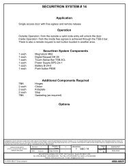
<strong>Securitron</strong> <strong>Magnalock</strong> Corp. www.securitron.com ASSA ABLOY, the global leader<br />
Tel 800.6<strong>24</strong>.5625 techsupport@securitron.com in door opening solutions<br />
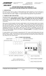
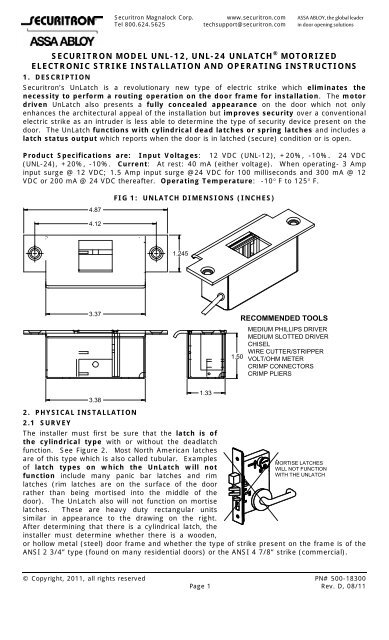
SECURITRON MODEL <strong>UNL</strong>-<strong>12</strong>, <strong>UNL</strong>-<strong>24</strong> <strong>UNL</strong>ATCH ® MOTORIZED<br />
ELECTRONIC STRIKE INSTALLATION AND OPERATING INSTRUCTIONS<br />
1. DESCRIPTION<br />
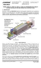
<strong>Securitron</strong>’s UnLatch is a revolutionary new type of electric strike which eliminates the<br />
necessity to perform a routing operation on the door frame for installation. The motor<br />
driven UnLatch also presents a fully concealed appearance on the door which not only<br />
enhances the architectural appeal of the installation but improves security over a conventional<br />
electric strike as an intruder is less able to determine the type of security device present on the<br />
door. The UnLatch functions with cylindrical dead latches or spring latches and includes a<br />
latch status output which reports when the door is in latched (secure) condition or is open.<br />
Product Specifications are: Input Voltages: <strong>12</strong> VDC (<strong>UNL</strong>-<strong>12</strong>), +20%, -10%. <strong>24</strong> VDC<br />
(<strong>UNL</strong>-<strong>24</strong>), +20%, -10%. Current: At rest: 40 mA (either voltage). When operating- 3 Amp<br />
input surge @ <strong>12</strong> VDC; 1.5 Amp input surge @<strong>24</strong> VDC for 100 milliseconds and 300 mA @ <strong>12</strong><br />
VDC or 200 mA @ <strong>24</strong> VDC thereafter. Operating Temperature: -10 F to <strong>12</strong>5 F.<br />
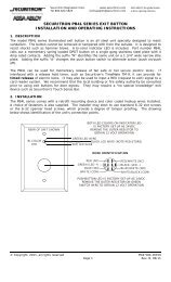
4.87<br />
4.<strong>12</strong><br />
3.37<br />
3.38<br />
FIG 1: <strong>UNL</strong>ATCH DIMENSIONS (INCHES)<br />
1.<strong>24</strong>5<br />
© Copyright, 2011, all rights reserved PN# 500-18300<br />
Page 1 Rev. D, 08/11<br />
1.33<br />
RECOMMENDED TOOLS<br />
MEDIUM PHILLIPS DRIVER<br />
MEDIUM SLOTTED DRIVER<br />
CHISEL<br />
WIRE CUTTER/STRIPPER<br />
1.50 VOLT/OHM METER<br />
CRIMP CONNECTORS<br />
CRIMP PLIERS<br />
2. PHYSICAL INSTALLATION<br />
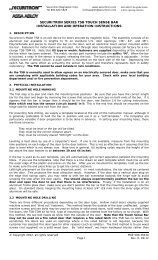
2.1 SURVEY<br />
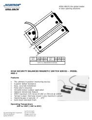
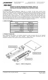
The installer must first be sure that the latch is of<br />
the cylindrical type with or without the deadlatch<br />
function. See Figure 2. Most North American latches<br />
are of this type which is also called tubular. Examples<br />
MORTISE LATCHES<br />
of latch types on which the UnLatch will not<br />
WILL NOT FUNCTION<br />
function include many panic bar latches and rim<br />
WITH THE <strong>UNL</strong>ATCH<br />
latches (rim latches are on the surface of the door<br />
rather than being mortised into the middle of the<br />
door). The UnLatch also will not function on mortise<br />
latches. These are heavy duty rectangular units<br />
similar in appearance to the drawing on the right.<br />
After determining that there is a cylindrical latch, the<br />
installer must determine whether there is a wooden,<br />
or hollow metal (steel) door frame and whether the type of strike present on the frame is of the<br />
ANSI 2 3/4” type (found on many residential doors) or the ANSI 4 7/8” strike (commercial).
FIG. 2: IDENTIFICATION OF CYLINDRICAL DEADLATCH AND SPRINGLATCH<br />
CYLINDRICAL DEADLATCH CYLINDRICAL SPRINGLATCH<br />
SPRINGLATCH<br />
DEADLATCH PIN<br />
2.2 HOLLOW METAL (STEEL) FRAME MOUNTING<br />
Most steel door frames include a 4 7/8” ANSI strike. This type of door preparation allows<br />
simple installation of the UnLatch. Remove the existing strike plate (it will be discarded) and<br />
experimentally try to fit the UnLatch in the resulting cavity. In some cases the cavity will be<br />
large enough to accommodate the UnLatch and you will have nothing to do but pull the wires up<br />
the hollow door frame and screw the UnLatch into place. In other cases you will find a “dust<br />
box” within the frame that will get in the way of the UnLatch. The dust box must be cleared<br />
away to make room for the UnLatch. Generally a sabre saw or a drill with a fly cutting bit is the<br />
most effective tool to do this. You can also find that the edge of the dry wall panel interferes<br />
with the UnLatch. Simply chip away some of the dry wall with a screwdriver to make room.<br />
Once you are able to fit the UnLatch into the frame, vacuum out any concrete dust and<br />
metal shavings (these can work their way into the UnLatch mechanism and cause problems).<br />
If the hollow metal frame has a 2 3/4” strike, installation of the UnLatch is still possible but it<br />
is much more difficult. You will have to route out a larger strike plate recess to convert the door<br />
preparation to 4 7/8 ANSI and this includes setting mounting tabs within the frame. Generally,<br />
commercial locksmiths have the skills to perform this work.<br />
2.3 WOOD FRAME MOUNTING<br />
<strong>Installation</strong> in a wood frame is straightforward. It is a question of using a chisel to create a<br />
space for the UnLatch behind the existing strike. The procedure depends on whether you have a<br />
4 7/8” ANSI strike (commercial) or a 2 3/4” ANSI strike (residential) on the door. In the case<br />
of a 4 7/8” ANSI strike, you will be using the existing holes that mount the strike to mount<br />
the UnLatch. Remove the strike and place the template on the door (registering it to the strike<br />
mounting holes). This will show you the space that must be chiseled out. As you get close to<br />
finishing the chiseling job, experimentally try to fit the body of the UnLatch in the cavity. This<br />
will avoid chiseling too big a space. A tight fit is preferred as it helps the solidity of the<br />
mounting which is important if the door receives abuse. Normally, with a wood frame, the wires<br />
will be run inside the wall. Simply drill from the back of the cavity you have created rearward<br />
into the wall space to admit the wires into the walls. To mount the UnLatch to the wood frame,<br />
use the two #<strong>12</strong> x 1” flat head wood screws which have been furnished. Once you are able to fit<br />
the UnLatch into the frame, vacuum out any concrete dust and metal shavings (these can<br />
work their way into the UnLatch mechanism and cause problems)<br />
In the case of a 2 3/4” ANSI strike, you will be using two new holes which are separated<br />
more widely to mount the UnLatch. You will also have to perform two chiseling operations. You<br />
will have to chisel a deep cavity for the body of the UnLatch and a shallow relief (3/32” or 2 MM<br />
deep) to fit the UnLatch’s face plate flush with the frame surface. A template (see page 9 of<br />
this manual) is provided to guide this chiseling but some work needs to be done to register the<br />
template to the frame:<br />
PN# 500-18300<br />
Page 2 Rev. D, 08/11
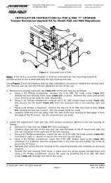
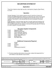
ANSI 2 3/4"<br />
STRIKE<br />
FIG. 3: MOUNTING ON WOOD DOOR WITH ANSI 2 3/4” STRIKE<br />
DRAW VERTICAL LINE<br />
THROUGH EDGE OF<br />
STRIKE HOLE WHICH<br />
CAPTURES LATCH<br />
STOP<br />
DRAW HORIZONTAL<br />
LINE BISECTING<br />
STRIKE HOLE<br />
First, draw two lines with a pencil on the door frame (see Figure 3).<br />
1/16"<br />
SET THE HORIZONTAL<br />
POSITION OF THE <strong>UNL</strong>ATCH<br />
SO THAT THE SEPARATION<br />
OF THE TWO PLUNGERS IS<br />
1/16" FARTHER FROM THE<br />
STOP THAN THE VERTICAL<br />
LINE YOU HAVE DRAWN<br />
USE THIS LINE TO<br />
CENTER THE<br />
<strong>UNL</strong>ATCH<br />
VERTICALLY<br />
TEMPLATE IS MARKED TO<br />
SET VERTICAL AND<br />
HORIZONTAL ALIGNMENT<br />
The first line is horizontal and bisects the 2 3/4” ANSI strike. The second is vertical and<br />
extends the edge of the strike opening which captures the latch. Next, remove the strike<br />
and introduce the template. Note that the template shows a center line arrow which you<br />
will use to position the UnLatch vertically by lining it up with the center line you have previously<br />
drawn. Next, the template has arrows at the top and bottom which line up with the vertical<br />
extension line you have drawn. These arrows position the UnLatch horizontally so that the<br />
separation between the two UnLatch plungers is 1/16” farther from the stop than the edge of the<br />
ANSI 2 3/4” strike. The latch is captured by the UnLatch at the separation line between the<br />
plungers and moving this position somewhat away from the stop increases adjustability of the<br />
installation.<br />
When you have the template correctly positioned, mark your top and bottom mounting holes.<br />
Then you will need to chisel out a shallow space 3/32” (2MM) under the complete outline of the<br />
UnLatch and chisel a rectangular cut-out as the template shows, 1 3/4” (44.5MM) deep to admit<br />
the UnLatch body. As you get close to finishing the chiseling job, experimentally try to fit the<br />
UnLatch body in the cavity. This will avoid chiseling too big a space. A tight fit is preferred as<br />
it helps the solidity of the mounting which is important if the door receives abuse. Normally,<br />
with a wood frame, the wires will be run inside the wall. Simply drill from the back of the cavity<br />
you have created rearward into the wall space to admit the wires into the walls. To mount the<br />
UnLatch to the wood frame, use the two furnished #<strong>12</strong> x 1” flat head wood screws.<br />
Note finally that we have implied that there are only two types of strikes on wooden doors: the<br />
ANSI 4 7/8” and the ANSI 2 3/4”. In residential applications there are also square shaped<br />
strikes (particularly found with inexpensive imported latches) which are smaller in outer<br />
dimensions than the 2 3/4” strike. These pose no difficulties. The installation techniques are<br />
the same as for an ANSI 2 3/4” strike.<br />
2.4 FINAL ADJUSTMENT WITH SPACERS<br />
For reliable operation, the door needs to close so that the latch easily enters and is retained by<br />
the UnLatch. The door should not have to be pushed to engage as can be the case with a poorly<br />
fitting or poorly closing door. To check this point, when the UnLatch has been mounted, after<br />
the door is closed and latched, you should be able to “rattle” the latch against the UnLatch<br />
plunger by pushing the door in and out. The amount of movement in the door latch should<br />
be about 1/16-1/8” (1.5-3MM).<br />
If the amount of slack or rattling is greater than 1/16-1/8”, you need the door to “close<br />
earlier”. In effect, the edge of the stop needs to be closer to the UnLatch. To adjust for this,<br />
first check to see if the stop has “silencers” on it. These are cylindrical rubber bumpers which<br />
quiet the noise of a closing door but also have the effect of making the door close earlier. If you<br />
have silencers and the door is still rattling too much, contact the factory for additional door stop<br />
spacers (the UnLatch is shipped with two). If you don’t have silencers, add one or two door stop<br />
spacers as is shown in Figure 4 to cause the door to close earlier.<br />
PN# 500-18300<br />
Page 3 Rev. D, 08/11
If the amount of slack or rattling is less than 1/16-1/8”, you have a “tight” door and the<br />
ability of the door to close and latch reliably is in question. To adjust for this, first check to see if<br />
the stop has “silencers” on it. These are cylindrical rubber bumpers which quiet the noise of a<br />
closing door but also have the effect of making the door close earlier. Remove the silencers<br />
(they pull out) and this will add slack to the closed position of the door. Be sure to check the<br />
entire length of the door for the silencers. If the door has no silencers and is still tight in<br />
latching, a locksmith should be engaged to readjust the door so that it closes properly or the<br />
installation will not be reliable.<br />
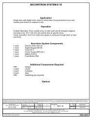
Note that Figure 4 illustrates the points made in this Section.<br />
FIG. 4: FINAL ADJUSTMENT OF DOOR CLOSING TOLERANCE<br />
VIEW OF <strong>UNL</strong>ATCH LOOKING STRAIGHT INTO DOOR FRAME<br />
DEADLATCH<br />
PLUNGER<br />
OPEN<br />
CAVITY<br />
SPRINGLATCH<br />
PLUNGER<br />
STOP SILENCER TWO SPACERS<br />
3. OPERATION<br />
While you can make a successful installation without knowing how the UnLatch functions, it’s<br />
best if you understand its operation in the event you run into any difficulties or questions. The<br />
operation of the UnLatch is, of course, intimately connected with the way latches and specifically<br />
deadlatches work on a door so we’ll cover this first.<br />
An ordinary latch is called a springlatch and it’s used on low security interior doors. One of the<br />
reasons that this latch’s security is low is that an intruder can retract the latch and open the<br />
door from the outside by slipping something flexible like a credit card in between the door and<br />
frame. To forestall this, the deadlatch was created. The deadlatch includes a deadlatch pin<br />
which is depressed against the flat part of the strike when the door is closed. When the<br />
deadlatch pin is depressed, the latch cannot be pushed in (by a credit card for instance); it is<br />
mechanically blocked. Deadlatches therefore offer a considerably higher level of security and<br />
this level of security is usually desired on doors subject to electric control from the installation of<br />
the UnLatch or other electric strike. The UnLatch makes full use of the deadlatch pin and<br />
preserves its security function. Springlatches however can also be employed with the UnLatch.<br />
Note that the UnLatch has two rectangular plungers which move under the control of a motor.<br />
We call these the springlatch plunger and deadlatch plunger. When the door is in the<br />
closed and secure position, the springlatch pushes in the springlatch plunger and the deadlatch<br />
pin rests on the deadlatch plunger which pushes in the deadlatch pin. This maintains the latch<br />
in the secure position and makes full use of the deadlatching function.<br />
When the UnLatch operates (the trigger wire connects to the +V wire), the deadlatch plunger<br />
retracts into the body of the UnLatch which allows the deadlatch pin to move out. Then both<br />
plungers simultaneously push the latch and deadlatch pin back into the latch body and the door<br />
may be opened from the outside. This operation takes about 1/3 of a second. When the trigger<br />
wire is removed from the +V wire, the UnLatch will return to its initial condition: the springlatch<br />
plunger will retract into the UnLatch body which allows the latch to resecure the door and the<br />
deadlatch plunger will push out depressing the deadlatch pin and freezing the latch for best<br />
security.<br />
PN# 500-18300<br />
Page 4 Rev. D, 08/11
FIG 5: <strong>UNL</strong>ATCH VIEW FROM ABOVE IN REST (SECURE) POSITION<br />
DEAD LATCH<br />
PLUNGER<br />
DEAD LATCH<br />
PIN<br />
SPRING LATCH<br />
SPRING LATCH PLUNGER<br />
DOOR STOP<br />
DOOR<br />
DOOR FRAME<br />
IN THE REST (SECURE) POSITION, THE SPRING LATCH IS ALLOWED TO COME OUT BY THE SPRING<br />
LATCH PLUNGER THEREBY SECURING THE DOOR. THE DEAD LATCH PLUNGER HOWEVER PUSHES<br />
IN THE DEAD LATCH PIN WHICH "FREEZES" THE SPRING LATCH FOR BEST SECURITY.<br />
DEAD LATCH<br />
PLUNGER<br />
DEAD LATCH<br />
PIN<br />
FIG 6: <strong>UNL</strong>ATCH IN OPERATION<br />
SPRING LATCH<br />
PLUNGER<br />
SPRING LATCH<br />
IN THE FIRST OPERATIONAL STEP, THE DEAD LATCH<br />
PLUNGER WITHDRAWS WHICH ALLOWS THE DEAD<br />
LATCH PIN TO COME OUT. THIS "UNFREEZES" THE<br />
SPRING LATCH<br />
DEAD LATCH<br />
PLUNGER<br />
DEAD LATCH<br />
PIN<br />
SPRING LATCH<br />
PLUNGER<br />
SPRING LATCH<br />
FINALLY, BOTH PLUNGERS MOVE<br />
FORWARD TOGETHER. THIS PUSHES OUT<br />
THE SPRINGLATCH AND DEADLATCH PIN<br />
AND THEREBY RELEASES THE DOOR.<br />
Note that if the door is heavily pre-loaded (by someone trying to pull it open before the UnLatch<br />
has released it for example), the UnLatch may not possess enough power to release the door.<br />
This is termed a stall condition for the motor. When a motor is stalled for a period of time, it<br />
can be damaged by heat build up as motors draw heavy current when they’re not permitted to<br />
move. The UnLatch automatically detects any stall condition that persists for more than<br />
1.5 seconds and shuts itself off. To operate, the UnLatch must simply be triggered again (which<br />
is the normal action for anyone who has failed to enter) and it will operate normally.<br />
PN# 500-18300<br />
Page 5 Rev. D, 08/11
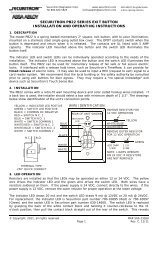
4. WIRING<br />
4.1 GENERAL ELECTRICAL CHARACTERISTICS<br />
The UnLatch is a six wire device. Power (<strong>12</strong> or <strong>24</strong>VDC depending on the model) is applied to the<br />
red and black wires observing polarity and power should be continuously present on these<br />
wires. If you connect power in reverse, the UnLatch will not operate but it will be<br />
damaged if left connected for an extended period of time. To operate the UnLatch, the<br />
trigger wire (orange) should be connected to the red wire (+V) via an external switch.<br />
When this connection is made, the UnLatch will release the door and keep it released so long as<br />
the red and orange wires are connected. When connection between these wires is broken, the<br />
door will be resecured (once it recloses). In certain applications the door is released all day and<br />
secured all night. There is no problem operating the UnLatch in this manner (continuous duty)<br />
but it is more common for the door to be released for only a few seconds at a time for controlled<br />
entry. This is typically done by connecting the orange and red wires together from relay<br />
contacts which close from an external card reader, digital keypad or keyswitch. The external<br />
control device includes a timing function which will operate the UnLatch for a few seconds to<br />
permit each entry. Like most conventional electric strikes, the UnLatch is fail secure which<br />
means that it will maintain the door in a secure position if power is lost. Entry is not possible<br />
but people can, of course, exit by simply turning the door handle or knob from the inside.<br />
DC<br />
POWER SUPPLY<br />
+ -<br />
<strong>UNL</strong>ATCH<br />
FIG. 7: <strong>UNL</strong>ATCH WIRING<br />
POWER SHOULD BE CONSTANTLY CONNECTED<br />
BLACK (NEG)<br />
RED (+V)<br />
ORANGE (TRIGGER)<br />
WHITE (STATUS: COM)<br />
GREEN (STATUS: N.C.)<br />
BLUE (STATUS: N.O.)<br />
CLOSURE<br />
BETWEEN +V IN<br />
AND TRIGGER<br />
RELEASES LATCH<br />
In normal operation, the UnLatch draws about 300 mA @ <strong>12</strong> VDC or 200 mA @ <strong>24</strong>VDC when it<br />
operates (the motor is moving) and a steady 40 mA at all times. Note that regulated input<br />
voltage is not required to operate the UnLatch. Full wave rectified DC is acceptable<br />
(transformer + bridge rectifier). When using a <strong>UNL</strong>-<strong>24</strong> with a <strong>24</strong>VAC transformer (TP-<strong>24</strong>-2) and<br />
bridge rectifier (BR-7) two additional components are required. These are two zener diodes<br />
(1N5333B, 5 watt, 3.3 volt or equivalent) that you will find in a package separate from the<br />
hardware pack. Because the peak voltage of a transformer and bridge rectifier combination can<br />
be as high as forty volts the diodes are required to drop the peak voltage into the operable<br />
range for the <strong>UNL</strong>-<strong>24</strong>. The following diagram (Figure 8) notes installation placement of the<br />
zener diodes.<br />
FIG. 8: ZENER DIODE PLACEMENT (<strong>UNL</strong>-<strong>24</strong> , TRANSFORMER, BRIDGE RECTIFIER)<br />
TP-<strong>24</strong>-2<br />
PLUG IN<br />
TRANSFORMER<br />
<strong>12</strong>0<br />
VAC<br />
IN<br />
VAC<br />
OUT<br />
Note diode orientation:<br />
CROSS BAR<br />
DENOTES CATHODE<br />
BANDED SIDE<br />
DENOTES CATHODE<br />
BR-4<br />
+<br />
PB2E<br />
NC<br />
C<br />
NO<br />
ORG<br />
RED<br />
BLK<br />
<strong>UNL</strong>-<strong>24</strong><br />
NC<br />
C<br />
NO<br />
TRG<br />
+<br />
PN# 500-18300<br />
Page 6 Rev. D, 08/11
Note: The addition of the zener diodes is only required when using the <strong>UNL</strong>-<strong>24</strong> with <strong>24</strong>VAC<br />
transformer and bridge rectifier. When using the <strong>UNL</strong>-<strong>12</strong> with <strong>12</strong>VAC transformer and bridge<br />
rectifier the zener diodes are not necessary.<br />
Power supply capacity, however, is ideally 3 Amps @ <strong>12</strong> VDC or 1.5 Amps @ <strong>24</strong> VDC for best<br />
operation. This is because the UnLatch’s motor (like all motors) will momentarily draw a lot<br />
more current if it has to “work harder”. This occurs for a very short time at motor start. If<br />
power supply capacity is limited, the UnLatch will still operate but it will operate a bit more<br />
slowly. The same condition of high current draw will occur for a longer period of time if the latch<br />
is binding which could be a permanent condition of the latch or could be because the person<br />
trying to enter is pulling on the door. Again, the UnLatch will function but more slowly and<br />
weakly. If a full capacity power supply is not practical, a 1 Amp power supply which includes<br />
battery backup such as <strong>Securitron</strong>’s model BPS-<strong>12</strong>-1 or BPS-<strong>24</strong>-1 is an equally effective device<br />
to power the UnLatch as the battery will provide the extra surge current as it is needed.<br />
Another point to note is that when one relatively large power supply is serving a number of<br />
UnLatches, the extra current capability will always be there as each UnLatch will operate at<br />
different times so each can draw extra current from the power supply when needed.<br />
If you are using a smaller capacity power source, you may well be satisfied with the<br />
operation of the UnLatch since the reduction in torque is only really noticeable when the door is<br />
pre-loaded. There is, however, an important electronic effect. During the brief moment (100<br />
milliseconds) while the motor is starting to move, the UnLatch will “try” to draw 3 or 1.5 Amps<br />
(depending on the voltage). A power supply of lower capacity will react to this condition by<br />
sharply dropping its voltage for the same brief period. While this will not harm the power<br />
supply, it may “crash” microprocessor equipped devices like digital keypads (such as <strong>Securitron</strong>’s<br />
model DK-11 or DK-26) that are being operated from the same power supply. If, therefore,<br />
your installation includes a digital keypad, or other microprocessor equipped device, make sure<br />
you have full power supply capacity or use a separate power supply for the keypad or other<br />
device.<br />
4.2 WIRE GAUGE SIZING<br />
If the power supply is some distance from the lock, voltage will be lost (dropped) in the<br />
connecting wires so that the UnLatch will not receive full voltage. The amount of voltage that is<br />
dropped in the wires depends on the resistance of the “round trip” wire run compared to the<br />
resistance of the UnLatch. The issue is complicated by the fact that the resistance of the<br />
UnLatch is 35 Ohms @ <strong>12</strong> VDC or <strong>12</strong>0 Ohms @ <strong>24</strong> VDC when it is operating (the motor is<br />
moving) but the resistance drops as low as 4 Ohms @ <strong>12</strong> VDC or 16 Ohms @ <strong>24</strong> VDC for 100<br />
milliseconds just as the motor starts. If the unit is denied full voltage during this motor start<br />
period, it will operate but with less torque so it will not release the latch as crisply when the<br />
latch has pre-load on it. Selecting thick wires to power the UnLatch will maintain strong<br />
torque even during start up. The following table shows distances from the UnLatch to the<br />
power source and calls out the wire gauge needed to fully maintain torque. Note that if your<br />
installation requires the power source to be more distant or has other complications, the factory<br />
can assist you.<br />
Distance (one way) 50 ft. (15 M) 100 ft. (30 M) 200 ft. (60 M)<br />
Wire Gauge for <strong>UNL</strong>-<strong>12</strong> 16 14 <strong>12</strong><br />
Wire Gauge for <strong>UNL</strong>-<strong>24</strong> 22 20 18<br />
4.3 LATCH STATUS SENSING<br />
The UnLatch includes a latch status sensing feature. When the door is<br />
closed and the door latch has engaged the UnLatch (specifically the<br />
spring latch plunger has been pushed in by the door latch), the UnLatch<br />
GREEN<br />
NC<br />
BLUE<br />
NO<br />
will report this secure condition by outputting a closed circuit<br />
condition between the white (COM) and green wires (see the drawing to<br />
the right). When the door is not securely latched, the closure will be<br />
WHITE<br />
COM<br />
between the white and blue wires. This dry SPDT output can carry 1 Amp @ 30 VDC<br />
maximum. This signal is normally connected to the building alarm system and it provides<br />
superior information compared to conventional door contacts which show only that the door is<br />
closed, not whether it is latched. Note that the UnLatch’s ability to report on the latched status<br />
PN# 500-18300<br />
Page 7 Rev. D, 08/11
of the door depends on it receiving constant power. Any time power is cut to the UnLatch,<br />
it will report the door as secure regardless of whether it is latched or not.<br />
The UnLatch uses the information as to whether the door is latched or not for a second purpose.<br />
The UnLatch will not operate unless the latch is in the secure position (the spring latch<br />
plunger is pushed in). The reason for this is to avoid a potential jam condition. If the door had<br />
not fully closed, the spring latch could be adjacent to the dead latch plunger and the dead latch<br />
pin would be resting on the metal “strike” casing of the UnLatch. In this condition, if the<br />
UnLatch was allowed to operate, the dead latch plunger would attempt to push the spring latch<br />
and it would be unable to do so because the dead latch pin would be pushed in by the metal<br />
casing of the UnLatch. The motor would jam. The UnLatch senses any motor jam condition and<br />
shuts itself down for that cycle but it is better not to operate at all unless the door is latched.<br />
Operationally, the door can be opened anyway (it is not latched) so there is no benefit to the<br />
end user from the UnLatch operating unless the door is latched.<br />
5. MAGNACARE LIFETIME REPLACEMENT WARRANTY<br />
For warranty information visit: www.securitron.com/en/site/securitron/About/MagnaCare-Warranty/<br />
PN# 500-18300<br />
Page 8 Rev. D, 08/11
APPENDIX A: TROUBLESHOOTING<br />
PROBLEM-- Unit will not operate when trigger wire is connected to +V.<br />
On a new installation, make sure that DC power (<strong>12</strong> or <strong>24</strong> volts depending on the model) is<br />
connected to the red and black wires with correct polarity. When this is confirmed note that the<br />
UnLatch will never operate unless the springlatch plunger is pushed in by the springlatch (see<br />
Section 3.3). You can be “fooled” by this feature if you’re trying to test operate the UnLatch<br />
with the door open. To do this, use a pencil or other similar object to lightly push in the<br />
springlatch plunger and then close the trigger wire to +V and you will see the UnLatch plungers<br />
move.<br />
On a service call for a unit with successful operating history, in addition to the checks mentioned<br />
above, check to see if the door and latch have gotten into a warped situation where there is<br />
heavy pre-loading on the door. The UnLatch’s motor may not be able to release the latch under<br />
this condition but you should be able to hear it trying to release the latch. The UnLatch will<br />
automatically shut down its motor if it can’t release the latch within 1.5 seconds. It will operate<br />
normally when it is re-triggered. You should be able to try operation by removing the preloading<br />
by pushing the door closed with enough force to counteract the pre-loading. Note that<br />
this situation is more likely if power supply capacity is less than 3 Amps (see Section 3.1).<br />
Corrections for this type of warped door situation is to have the door serviced and possibly<br />
increase the capacity of the power supply.<br />
If the unit still will not function, note that it does have an internal microprocessor that may have<br />
gone into a crash condition which may leave the unit’s gears and plungers in an unusual<br />
position. This can happen sometimes if the unit is under-powered (see Section 3.1) and has<br />
consequently stalled (the motor is not receiving enough power to operate the latch). While the<br />
motor is in the process of stalling, voltage to the processor will sharply drop and this can crash<br />
the microprocessor. A crash can also occur as a random event but this is unusual. There are<br />
two recovery methods that may be used to recover the unit’s operation. The first technique is a<br />
simple reset achieved by cycling power to the unit. Remove power (+V) from the unit’s red wire<br />
momentarily. After power is reapplied, the unit may reset and begin normal operation. If this<br />
recovery method did not work perform the second recovery method (POWER ON RESET).<br />
Remove power (+V) from the unit’s red wire. Connect the unit’s red and orange wires together.<br />
Now reapply power (+V) to both the orange and red wires simultaneously. This re-initializes the<br />
firmware and may cycle the unit to the unlocked position. Once this operation has been<br />
performed, return the unit to standard wiring (orange only connects to +V to trigger the unit.)<br />
Finally, the unit could have experienced motor failure or other internal electronic failure. It is<br />
repairable by the factory.<br />
PROBLEM -- Unit will occasionally not operate.<br />
Generally, this comes from too much door pre-loading possibly coupled with a low capacity<br />
power source. When the UnLatch can’t generate enough torque to release the latch, it<br />
automatically shuts down but then operates the next time it is triggered. See the previous<br />
paragraph.<br />
PROBLEM -- Latch does not re-secure when the door re-closes.<br />
This is not a problem with the UnLatch but is rather a problem with the installation. The latch is<br />
simply not moving into position. Make sure the door closer is properly operating to re-close the<br />
door with reasonable force. Next, re-read Section 2.5 to make sure the UnLatch is in the correct<br />
position with respect to the door stop.<br />
PROBLEM -- Latch status sensing does not function.<br />
The latch status output contacts (see Section 3.3) will change state when the springlatch plunger<br />
is pushed in. To check this, therefore, push the springlatch plunger lightly in with a pencil or<br />
other similar object. Make sure the unit is receiving power when you make this check or the<br />
output contacts will not switch. If they still do not switch, the unit will need to be returned to<br />
the factory for repair.<br />
PATENTS<br />
The UnLatch is covered under U.S. patents #5,474,342 and #6,022,056 with other US and<br />
international patents pending.<br />
PN# 500-18300<br />
Page 9 Rev. D, 08/11
TEMPLATE FOR CUTTING OUT ANSI 2 ¾” STRIKE PREPARATION AND INSTALLING <strong>UNL</strong>ATCH ON<br />
WOODEN FRAME<br />
4 7/8"<br />
CENTER LINE<br />
4 1/8"<br />
1 1/4"<br />
DOTTED LINE SHOWS AREA TO<br />
CHISEL OUT 1 3/4" DEEP FOR<br />
INSTALLATION IN WOOD FRAME<br />
HORIZONTAL<br />
ALIGNMENT<br />
ARROWS (SEE<br />
FIG. 3)<br />
PN# 500-18300<br />
Page 10 Rev. D, 08/11